
KNB Series
3MARCH 2008
Technical Characteristics
Medium Density PCB ConnectorsMIL C 55302 ESA/ESCC3401/016, 3401/017NF C-UTE C 93-424
· Equipped with 0.60mm rear removable contacts
· High density interconnection
· Up to 120 signal contacts / 2 rows
· 2.54mm between rows
· 1.27mm between contacts quincuncial
· Low contact insertion
· Low contact resistance
· Polarization by guiding or locking devices
· 5000 mating and unmating cycles
MATERIALS
Moulding Glass fiber filled diallyl - phtalate
Contacts Brass or bronze
Guides - coding styles - screws Stainless steel or nickel plated brass or ARCAP
PLATING Standard ESA
Pin 0.25μm Gold/1.27μm Ni 1.27μm Gold/1.27μm Ni (min)
Socket body0.25μm Gold/1.27μm Ni on activ area
0.25μm Gold/1.27μm Ni (min)1.27μm Ni on non activ area
Socket wires 1μm Gold/0.20μm Ni 1.27μm Gold/0.20μm Ni (min)
Guides (brass) Ni Ni
DIELECTRIC WITHSTANDING VOLTAGE 1 200Vrms
CURRENT RATING (at 25 °C)Standard quality: 3A Max
ESA approved: 5A Max
INSULATION RESISTANCE > 104MΩ (500Vcc)
CONTACT RESISTANCE � 8mΩ
TEMPERATURE RANGE -55°C +125°C
CONTACTS HYPERTAC® type Ø 0.60mm rear removable
PITCH2.54mm between rows
1.27mm between quicuncial contacts
GUIDINGBy two outside guides (2 guiding styles)
and one central guide (3 guiding styles)
KEYINGBy rotating of outside polarised guides
(Up to 36 keyings)
MASS & POWER CONTACTSHYPERTAC® type can be used instead
of outside guides

KNB Series
MARCH 20084
Ordering Information
N 1.27 mm pitch, rear removable contacts
B 2 rows
017 029 041 053
096 120
065
072 084
Female plug
Male plug
Tinned female plug*
10
20
Through board solder - 90°- length 3mm
11 Through board solder - 90°- length 4mm
Crimp (Contact: see p. 33) 51 Wire wrap (3 wrapping levels)
21 Double crimp (Contact: see p. 33)
40 Solder bucket
91 Female - male
30 Through board solder - straight
110
113
121
Male polarised, transverse mount, standard plug
111 Male polarised, vertical mount
Male polarised, float mount
Female polarised, vertical mount
123 Female polarised, float mount
124 Female polarised, transverse mount
145 Male polarised, transverse mount on receptacle only
208
212
Jackscrew, transverse mount
Jackscrew, transverse mount
215 Jackscrew, vertical mount
219 Jackscrew, vertical mount
LOCKING STYLES (see p. 13-14)
Female receptacle
201 1/4 turn, free connector
203 1/4 turn, transverse mount
Male plug
125
127
Male unpolarised, transverse mount
126 Female unpolarised, vertical mount
Male unpolarised, vertical mount
130 Female unpolarised, vertical mount
131 Male unpolarised, transverse mount
132 Female unpolarised, transverse mount
133 Female all polarised, transverse mount
190 Female power or mass contact, vertical mount 191 Male power or mass contact, vertical mount
207 Jackscrew, free connector
211 Jackscrew, free connector
290 Jackscrew, vertical mount
204 1/4 turn, transverse mount
202 1/4 turn, vertical mount
210 Jackscrew, free connector
: To convert HYPERTAC references to ESA references, see tables 1, 2 & 3 on next page
GUIDE STYLES (see p. 10-11) - (Consult us for special guides)
MOUNTING HARDWARE
232 Jackscrew, with operation button
12
13
16
17
1A
14
15
18
19
1C
54
55
-
-
-
1B 1D -
54
55
56
57
5A
5B
Tinned male plug*
NF C-UTE C 93-424
MIL-C-55302
ESA/ESCC 3401/01601B
SPACE GRADE
Tinned female plug**
Tinned male plug**
Female receptacle
Male receptacle
Tinned female receptacle*
22
23
26
27
2A
24
25
28
29
2C
44
45
-
-
-
2B 2D -
44
45
46
47
-
-
Tinned male receptacle*
Tinned female receptacle**
Tinned male receptacle**
* For 90° & straight terminations
(splicing on PCB)
**RoHS compliant for 90° & straight
terminations (splicing on PCB)
BN 017 22 51 121SERIES
PITCH OR TYPE
NF C-UTE C 93-424
MIL-C-55302
ESA/ESCC 3401/01601B
SPACE GRADE
K
For the right angle 053 layout,KNB must be replaced byKXB (details on page18)
TERMINATION STYLES (see p. 6)
MODEL
NUMBER OF CONTACTS
MOULDING POLARITY

KNB Series
5MARCH 2008
ESA & HYPERTAC Correspondance Table
Guideless Connector
KNB _______ 10 125
KNC _______ 10 125
KN _________ 127
KN _________ 126
KNB _________ 131
KNB _________ 132
KNB _______ 10 110
KNC _______ 10 110
ESCC COMPONENT NUMBER
MOUNTINGSee table 1
TERMINATION STYLESee table 2
LOCKING TYPE - ON LEFT SIDESee table 3
LOCKING TYPE - IN CENTERFor 2 guide connectors
For 3 guide connectors, see table 3
esaPart numbers esaPart numbers esaPart numbers esaPart numbers
01Plug KNB 017
02Plug KNB 029
03Plug KNB 041
04Plug KNB 053
05Plug KNB 065
07Plug KNB 084
08Plug KNB 096
10Plug KNB 120
12Plug KNC 160
13Receptacle KNB 017
14Receptacle KNB 029
15Receptacle KNB 041
16Receptacle KNB 053
17Receptacle KNB 065
19Receptacle KNB 084
20Receptacle KNB 096
22Receptacle KNB 120
24Receptacle KNC 160
56Plug KNB 072
57Receptacle KNB 072
58Plug KNC 062
59Receptacle KNC 062
60Plug KNC 080
61Receptacle KNC 080
62Plug KNC 098
63Receptacle KNC 098
MCBent male 10
MLBent long male 11
MRCrimp male 20
MDStraight male 30
MSSolder bucket male40
MYMini-wrapping male51
FCBent female 10
FLBent long fem. 11
FRCrimp female 20
FDStraight female 30
FSSolder bucket fem.
FYMini-wrapping fem. 51
FMFemale-male 91
Example: KNB 029 44 40 113
TABLE 1
00
LOCKING TYPE - ON RIGHT SIDESee table 3
TABLE 2
00
26
27
28
29
31
32
33
34
35KN _________ 111
36KN _________ 121
40KNB _________ 145
41KNB _________ 124
43KNC _______ 10 230
45KN _________ 232
46KN _________ 231
47KN _________ 207
48KNB _______ 10 208
49KNC _______ 10 209
50KN _________ 210
51KN _________ 211
52KNB _________ 212
53KN _________ 215
54KN _________ 123
55KN _________ 113
71KNB _______ 11 125
72KNB _______ 11 110
73KNB _______ 10 230
74KNC _________ 124
75KNC _________ 132
76KNC _______ 11 110
77KNC _______ 11 125
79KNB _______ 11 208
TABLE 3
44Female receptacle
45Male receptacle
54Plug female
55Plug male
REMINDER SPATIAL P.P.P. (Party Polarity Protection) EXAMPLE
KNB 029 44 40 113P.P.P.
80KN _________ 219
81KN _________ 290please consult us
esaPart numbers esaPart numbers esaPart numbers esaPart numbers
550055FS1434 01 016 01 B
--

KNB Series
MARCH 2008
Dimensions are in mm
6
Contact Terminations
Ø 0
.60 4.80 Max.
4.80 Max.Ø 0
.60
Ø 0
.60
4.80 Max.
4.80 Max.
1.08
Ø 0.60
2.54
Ø 0
.60
4.80 Max. 1.08
Ø 0.60
2.545.08
2.54
X
3.90Ø 0.60
X X
MRFR
Ref
5.08
2.54
4.80 Max.
X Ø
0.6
03.90Ø 0.60ML
FL
MCFC
Ref: 11 (X= 4)
Ref: 10 (X= 3)
Ref :
Ref
90° through board solder
Ø 0
.90
Ø 1
.30
4.40 4.80 Max.
Ø 0
.60
Ø 0
.90
Ø 1
.30
4.40
Hol
e Ø
0.9
0Ø
1.3
0
4.80 Max.
4.40
Ø 0
.60
Hol
e Ø
0.9
0
4.40 Ø 1
.30
Ref: 20Crimp (AWG 28-26 & 24-22)
X Ø 0
.60
Ø 0
.60
5.604.80 Max.
Ø 0
.60
Ø 0
.60
4.80 Max.
Ø 0
.60
5.60
Ø 0
.60
X
Ø 0
.60MD
FDRef
Ref: 30Straight through board solder
Ø 0
.60
4.80 Max. Ø 1
.45
Hol
e Ø
1.0
0
5.404.90
Hol
e Ø
1.0
0Ø
1.4
5
Ø 1
.45
Hol
e Ø
1.0
0
4.80 Max.
5.40Ø 1
.45
Ø 0
.60
Ø 0
.60
Ø 0
.60
Ø 1
.45
Hol
e Ø
1.0
0
4.90
MSFS
Ref
Ref: 40Solder bucket (AWG 22 Max.)
4.80 Max.
Ø 0
.60
14.1014.10
� 0.60 � 0.604.80 Max.
14.10
� 0.60
14.10
� 0.60MYFY
Ref
Ref: 51Wire wrap (3 wrapping levels)
Ø 0
.60
4.80 Max.
Ø 0
.60
4.80 Max.
FMRef
Ref: 91Saver (Female-Male)
Ref: 90Saver (Male-Male)
4.80 Max.
Ø 0
.60
Hol
e Ø
0.9
0H
ole
Ø 1
.50
Hol
e Ø
0.0
9H
ole
Ø 1
.50
Hol
e Ø
0.9
0H
ole
Ø 1
.50
Ø 1.80Ø 1.80 Ø 1.80
Ø 1.30 Ø 1.30 Ø 1.304.80 Max.
4.40 4.40 4.404.40
Ø 0
.60
ajouter ligne 21
Hol
e Ø
0.9
0
Hol
e Ø
1.5
0
Ø 1.80 Ø 1.30Ref: 21Crimp (AWG 28-26 & 24-22) & Crimp on sheath (Ø 1.45)
X: Ref 30 = 4.50, ref 31 = 5.60
Plugs Receptacles
Male Female Female Male

KNB Series
7MARCH 2008
Dimensions are in mm
Dimensions
7 M
ax.
C
==
B
A
3.105.08 2.54
2.54 5.081.27
8.05
Max
.
8.05
Max
.
3.90
B
A
C
2.545.08
==2.
54 3.15
6.40
Max
. 5.081.27
=
6.40
Max
.
2.545.08 1.27
3.15
D
5.08
7.62
D
DD
2.54 =
= =
8.05
Max
.
7 M
ax.
3.90
B
A
B
8.05
Max
.
41Nb. of
contacts
B Max.
Plugs Receptacles
72 to 120 Contacts
17 to 65 Contacts

KNB Series
MARCH 20088
Plu
g
Rec
epta
cle
Str
aigh
t
31 40 21 5111
Contact
Wire
wra
p -
PP
C
Crim
p
Sol
der
buc
ket
90°
30
FF 12
FM 13
EM
EF
EM
EF
FF 12
FM 13
FF 12
FM 13
FF
FM
EM
EF
13
FF
FM
EM
EF
12
13
23
22
FF
FM
EM
EF
12
13
23
22
EM
EF
FF
FM
23 22 12 13
EM
EF
FF
FM
23 22 12 13
EM
EF
FF
FM
23 22 12 13
132133190Moulding
Pol
arity
23
22
23
22
12
23
22
Legend:
Compatible
Compatible providedthat PCB does not protect male contacts
FF = Female Plug FM = Male Plug EF = Female ReceptacleEM = Male Receptacle
G u i d i n g d e v i c e s
Guide Device andCompatibility
10 20

KNB Series
9MARCH 2008
Polarity
Straight
90°
Solder bucket
Crimp
Wire wrap
21
40
31
11
51
Con
tact
20
10
30
Receptacle
Plug
EM
EF
FF
FM
23 22 12 13
EM
EF
FF
FM
23 22 12 13
EM
EF
FF
FM
23 22 12 13
EM
EF
FF
FM
23 22 12 13
EM
EF
FF
FM
23 22 12 13
Mou
ldin
g
191
145
131
127
125
113
111
110
121123124126130 Female guides
Mal
e gu
ides
Gu
idin
g d
ev
ice
s
G u i d i n g d e v i c e s
Nota: For the global unders-tanding of the chart, pleaseprint pages 8 and 9
Polarity TerminationChart

KNB Series
MARCH 2008
Dimensions are in mm
10
7.00
M 2
.50 5.80
4 mm across flats
7.00
M 2
.50 2.10
4 mm across flats
7.00
Ø 7
.50
For 2 mm thickness
Ø 6
.00
Ø 4.005.80
Ref: 111Ref : 35
Polarised vertical mountRef: 121Ref : 36
Polarised vertical mount
Ref: 113Ref : 55
Polarised vertical float mount 7.00
Ø 7
.50
Ø 6
.00
2.10Ø 4.00
For 2 mm thickness
Ref: 123Ref : 54
Polarised vertical float mount
7.00
M 2
.50
M 2
.50
5.80
4 mm across flats
Ref: 127Ref : 28
Unpolarised vertical mount
7.00 2.10
4 mm across flats
Ref: 126Ref : 29
Unpolarised vertical mount
11.20
8.00Ref: 133All polarised transverse mount
7.00
4 mm across flats
Ref: 130All polarised vertical mount
11.20
5.80
M 1.60
8.00
M 1.60
M 1.60
11.20
8.00 2.10
M 1.6011.20
8.00
Ø 3
.50
Ø 3
.50
Ø 3
.50
Ø 3
.50
Ø 3
.50
2.10
11.20
5.80
M 1.60
8.00Ref: 131Ref : 31
Unpolarised transverse mount
Ref: 124Ref : 41
Polarised transverse mount
Ref: 132Ref : 32
Unpolarised transverse mount
Ref: 145Ref : 40
Polarised transverse mount
M 2
.50
Guide StylesPlugs & Receptacles
Male Female

KNB Series
11MARCH 2008
Dimensions are in mm
Ref: 10 110Ref : 33X = 1.60 Y= 3.20
Ref: 11 110Ref : 72X = 2.40 Y= 4.90
Polarised transverse mount
Ref: 191
Power or mass transverse mountRef: 190
Power or mass vertical mount
Ref: 10 125Ref : 26X = 1.60 Y= 3.20
Ref: 11 125Ref : 71X = 2.40 Y= 4.90
Unpolarised transverse mount
X (P
CB
thic
knes
s)
Ø 2
.50
Y M
ax.
Y M
ax.
3.905.80
3.905.80
4 mm across flats
Ø 2
.50
4 mm across flats
X (P
CB
thic
knes
s)
4 mm across flats
3.20
Max
.
Ø 1
.70
Ø 2
.50
Ø 2.50
3.904.00 5.50
4.50
M 2
.50
Ø 3
.70
Ø 2
.00 2.10
4 mm across flats
PCB
thick
ness
1.6
0
Guide StylesMale Plugs Only
Plugs & Receptacles
Male Female

KNB Series
MARCH 200812
R
P
R
P
R
P
R
P
R
P
R
P
R
P
232 219 215 212 208 204 202
201
203
205
207
231
211
290
PRPRPRPRPRPRPR
210
PR
Plug
Receptacle
Mou
ldin
g
Plu
g
Rec
epta
cle
MouldingFemale locking devices
Mal
e lo
ckin
gd
evic
es
Compatible
Locking DeviceCompatibility Chart

KNB Series
13MARCH 2008
Dimensions are in mm
Male Locking Styles
Ref: 201
Ref: 203
Ref: 207Ref : 47
Jack 1/4 turn lock, free connector
Jackscrew, free connector
Ref: 211Ref : 51
Ref : 81
Ref : 46
Jackscrew, free connector
Ref: 231Jackscrew, vertical mountJack 1/4 turn lock, transverse mount
0.40 Ø 6
.40
Max
.
5.20 15.00
Ø 2
.50
0.40
4 mm across flats
5.20 15.00
3.50
Ø 6
.40
Max
.
Ø 2
.50
Ø 2.50
M 2
.50
M 2
.50
5.80 11.80
4 m
m a
cros
s fla
ts5 mm across flats
unremovable screw
unremovable screw
M 1
.60
0.50
12.50 unlocked 8.50 locked
6.50 Max.
5.50 mm across flats
M 2
.50
5.80 8.00
4 mm across flats
Ref: 290Jackscrew, vertical mount
0.45
Ø 4
.00
M 1
.60
6.50
M 3
9.80
5.5 mm across flats
PCB thickness 1.60
Plugs & Receptacles

KNB Series
MARCH 2008
Dimensions are in mm
14
Female Locking Styles
Plugs & Receptacles
Ref: 202
Ref: 204
Ref: 210
Jack 1/4 turn lock, vertical mount
Jackscrew, free connector
Ref: 215Ref : 53
Jackscrew, vertical mount
Jackscrew, vertical mountRef: 208Jackscrew, transverse mount
Jack 1/4 turn lock, transverse mount
Ref: 232Rotating jackscrew, free connector
Ref: 219Ref : 80
11.20
Ø 3
.80
Ø 3
.80
Ø 3
.80
2.80
M 1.60
8.10
Ø 3
.50 4.80 7.00
Ø 3
.60
Ø 5
.00
M 3
4 mm across flats
4.80
Ø 3
.60
3.50
Ø 5
.00
M3
Ø 2.50
4.00 Max. 4.80Ø
3.8
0
M 2
.504.00
4 mm across flats
2.80 7.00
M 2
.50
4 mm across flats
Term.: 10PCB thickness 1.60Ref : 48
Jackscrew, transverse mountRef: 212
1411.20
4.80
Ø 3
.504.00
M 1.60
Ref : 52
Term.: 11PCB thickness 2.40Ref : 79
4.80 4.00
Ø 3
.60
Ø 5
.00
M 3 Ø 4
.00
M 3
6.30
5.50 on flatsRetaining pin
Ref : 50 Ref : 45

KNB Series
15MARCH 2008
017
029
041
053
065
072
084
096
120
Mating Side Layout ViewPlugs Receptacles

KNB Series
MARCH 2008
Dimensions are in mm
16
Panel Preparation Details
**
17 to 65 Contacts 72 to 120 Contacts
Panel: Female or Male, plugs or receptacles, terminations 20 - 40 - 51Guide Styles: 111 - 121 - 126 - 127 - 130 - 190 (Fixed Mount). 113 - 123 (Float Mount)
Locking Styles: 202 - 215* - 219 - 231
Nb. ofcontacts
* For ref 215, holes �� 3.20 min.

KNB Series
17MARCH 2008
Dimensions are in mm
Nb. ofcontacts
Board Preparation Details
* *
Daughter Board: Female or Male, plugs or receptacles, 90° terminations(1) Guide Styles: 124 - 131 - 132 - 133 - 145 Locking Styles: 204 - 212
(2) Guide Styles: 110 - 125 - 191 Locking Styles: 203 - 208
Mother board17 to 65 Contacts 72 to 120 Contacts
* For ref 215, holes �� 3.20 min.
Mother Board: Female or Male, plugs or receptacles, straight solder terminationsGuide Styles: 111 - 121 - 126 - 127 - 130 - 190 Locking Styles: 202 - 215* - 219 - 231
Daughter board17 to 65 Contacts 72 to 120 Contacts

KXB Series
MARCH 2008
Dimensions are in mm
18
Right Angle Monobloc Insulator
· Concerns the 053 layout on standard or MIL C plating
· Thermoplastic material
· Compliant with NF-UTE-C 93-424
· Contact anti-rotation device
· Conserve the other KNB characteristics
DimensionsPlug Receptacle
76.20
7.90
6.40
3.152.54 5.08
1.27
84.10
1.27x52=66.04
2 chamfers (45°x1.80)
68.50
70.00
2.54 1.27
1.27
11.8
09.
30
12
3 4
12
3 4
84.10
7.90
6.802.90
2.545.08
1.2776.20
70.00
1.27x52=66.04
2 chamfers (45°x1.80)
68.50 Max.
2.54
1.27
1.27
11.8
09.
30
12
3 412
3 4
053
Part Number
1-2-
-- --
PlugReceptacle
1011
Right angle termination
Fixing devicesX Thermoplastic material
KXB ---
KNC/KND Series
19MARCH 2008
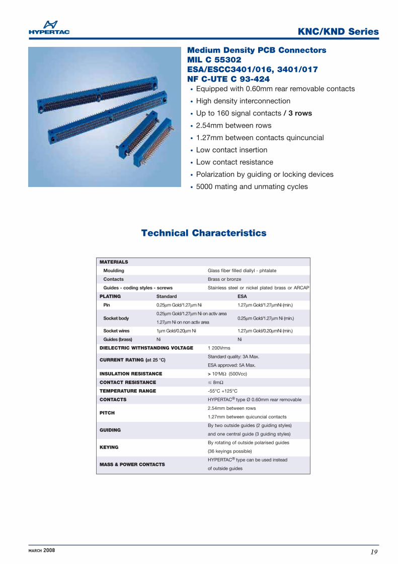
Technical Characteristics
Medium Density PCB ConnectorsMIL C 55302 ESA/ESCC3401/016, 3401/017NF C-UTE C 93-424
· Equipped with 0.60mm rear removable contacts
· High density interconnection
· Up to 160 signal contacts / 3 rows
· 2.54mm between rows
· 1.27mm between contacts quincuncial
· Low contact insertion
· Low contact resistance
· Polarization by guiding or locking devices
· 5000 mating and unmating cycles
MATERIALS
Moulding Glass fiber filled diallyl - phtalate
Contacts Brass or bronze
Guides - coding styles - screws Stainless steel or nickel plated brass or ARCAP
PLATING Standard ESA
Pin 0.25μm Gold/1.27μm Ni 1.27μm Gold/1.27μmNi (min.)
Socket body0.25μm Gold/1.27μm Ni on activ area
0.25μm Gold/1.27μm Ni (min.)1.27μm Ni on non activ area
Socket wires 1μm Gold/0.20μm Ni 1.27μm Gold/0.20μmNi (min.)
Guides (brass) Ni Ni
DIELECTRIC WITHSTANDING VOLTAGE 1 200Vrms
CURRENT RATING (at 25 °C)Standard quality: 3A Max.
ESA approved: 5A Max.
INSULATION RESISTANCE > 104MΩ (500Vcc)
CONTACT RESISTANCE � 8mΩ
TEMPERATURE RANGE -55°C +125°C
CONTACTS HYPERTAC® type Ø 0.60mm rear removable
PITCH2.54mm between rows
1.27mm between quicuncial contacts
GUIDINGBy two outside guides (2 guiding styles)
and one central guide (3 guiding styles)
KEYINGBy rotating of outside polarised guides
(36 keyings possible)
MASS & POWER CONTACTSHYPERTAC® type can be used instead
of outside guides

KNC/KND Series
MARCH 200820
C
KNC
3 rows centered fixing D 3 rows uncentered fixing
062 080 098 160
KND 026 044 062 080 098 108 126 144
PITCH OR TYPEN 1.27 mm pitch, rear removable contacts
SERIES 22062CN
MOULDING POLARITY
Female plug
Male plug
Tinned female plug*
10
20
Through board solder - 90°- length 3mm
11 Through board solder - 90°- length 4mm
Crimp (Contact: see p. 31) 51 Wire wrap (3 wrapping levels)
21 Double crimp (Contact: see p. 33)
40 Solder bucket
91 Female - male
30 Through board solder - straight
12
13
16
17
1A
14
15
18
19
1C
54
55
-
-
-
1B 1D -
54
55
56
57
5A
5B
Tinned male plug*
NF C-UTE C 93-424
MIL-C-55302
ESA/ESCC 3401/01601B
SPACE GRADE
Tinned female plug**
Tinned male plug**
Female receptacle
Male receptacle
Tinned female receptacle*
22
23
26
27
2A
24
25
28
29
2C
44
45
-
-
-
2B 2D -
44
45
46
47
-
-
Tinned male receptacle*
Tinned female receptacle**
Tinned male receptacle**
* For 90° & straight terminations
(splicing on PCB)
**RoHS conpliant for 90° & straight
terminations (splicing on PCB)
NF C-UTE C 93-424
MIL-C-55302
ESA/ESCC 3401/01601B
SPACE GRADE
Ordering Information
110
113
121
Male polarised, transverse mount, standard plug
111 Male polarised, vertical mount
Male polarised, float mount
Female polarised, vertical mount
123 Female polarised, float mount
124 Female polarised, transverse mount
145 Male polarised, transverse mount on receptacle only
208
212
Jackscrew, transverse mount
Jackscrew, transverse mount
215 Jackscrew, vertical mount
219 Jackscrew, vertical mount
LOCKING STYLES (see p. 29-30)
Female receptacle
201 1/4 turn, free connector
203 1/4 turn, transverse mount
Male plug
125
127
Male unpolarised, transverse mount
126 Female unpolarised, vertical mount
Male unpolarised, vertical mount
130 Female unpolarised, vertical mount
131 Male unpolarised, transverse mount
132 Female unpolarised, transverse mount
133 Female all polarised, transverse mount
190 Female power or mass contact, vertical mount 191 Male power or mass contact, vertical mount
207 Jackscrew, free connector
211 Jackscrew, free connector
290 Jackscrew, vertical mount
204 1/4 turn, transverse mount
202 1/4 turn, vertical mount
210 Jackscrew, free connector
: To convert HYPERTAC references to ESA references, see tables 1, 2 & 3 on next page
GUIDE STYLES (see p. 26-27) - (Consult us for special guide)
MOUNTING HARDWARE
232 Jackscrew, with operation button
K 12151
MODEL
NUMBER OF CONTACTS
TERMINATION STYLES (see p. 22)

KNC/KND Series
21MARCH 2008
Dimensions are in mm
ESA & HYPERTAC Correspondance Table
Guideless Connector
KNB _______ 10 125
KNC _______ 10 125
KN _________ 127
KN _________ 126
KNB _________ 131
KNB _________ 132
KNB _______ 10 110
KNC _______ 10 110
ESCC COMPONENT NUMBER
MOUNTINGSee table 1
TERMINATION STYLESee table 2
LOCKING TYPE - ON LEFT SIDESee table 3
LOCKING TYPE - IN CENTER
esaPart numbers esaPart numbers esaPart numbers esaPart numbers
01Plug KNB 017
02Plug KNB 029
03Plug KNB 041
04Plug KNB 053
05Plug KNB 065
07Plug KNB 084
08Plug KNB 096
10Plug KNB 120
12Plug KNC 160
13Receptacle KNB 017
14Receptacle KNB 029
15Receptacle KNB 041
16Receptacle KNB 053
17Receptacle KNB 065
19Receptacle KNB 084
20Receptacle KNB 096
22Receptacle KNB 120
24Receptacle KNC 160
56Plug KNB 072
57Receptacle KNB 072
58Plug KNC 062
59Receptacle KNC 062
60Plug KNC 080
61Receptacle KNC 080
62Plug KNC 098
63Receptacle KNC 098
MCBent male 10
MLBent long male 11
MRCrimp male 20
MDStraight male 30
MSSolder bucket male 40
MYMini-wrapping male 51
FCBent female 10
FLBent long fem. 11
FRCrimp female 20
FDStraight female 30
FSSolder bucket fem.40
FYMini-wrapping fem. 51
FMFemale-male 91
Example: KNC 062 44 20 121
TABLE 1
LOCKING TYPE - ON RIGHT SIDESee table 3
TABLE 2
00
26
27
28
29
31
32
33
34
35KN _________ 111
36KN _________ 121
40KNB _________ 145
41KNB _________ 124
43KNC _______ 10 230
45KN _________ 232
46KN _________ 231
47KN _________ 207
48KNB _______ 10 208
49KNC _______ 10 209
50KN _________ 210
51KN _________ 211
52KNB _________ 212
53KN _________ 215
54KN _________ 123
55KN _________ 113
71KNB _______ 11 125
72KNB _______ 11 110
73KNB _______ 10 230
74KNC _________ 124
75KNC _________ 132
76KNC _______ 11 110
77KNC _______ 11 125
79KNB _______ 11 208
TABLE 3
44Female receptacle
45Male receptacle
54Plug female
55Plug male
REMINDER SPATIAL P.P.P. (Party Polarity Protection) EXAMPLE
KNB 029 44 40 113P.P.P.
80KN _________ 219
81KN _________ 290please consult us
esaPart numbers esaPart numbers esaPart numbers esaPart numbers
360036FR5934 01 016 01 B
For 2 guide connectors
For 3 guide connectors, see table 3
00
--

KNC/KND Series
MARCH 2008
Dimensions are in mm
22
Contact TerminationsPlugs Receptacles
Male Female Female Male

KNC/KND Series
23MARCH 2008
Dimensions are in mm
69
A
B Max.
26 44 62Number of contacts 80
D
98 108 126 144 160
- -
- -
60.96 76.20
84.20
- - 9.45
91.44
99.50
9.45 -
-
-
-
-
-
149.86
158
9.30
4.70- - 4.42 4.42 4.42
Plug&Receptacle
8.95 8.95 8.95 -8.95 8.95 8.95 8.95 8.95
C Max. 9.55 9.55 9.55 -9.55 9.55 9.55 9.55 9.55
3.15 3.15 3.15 -3.15 3.15 3.15 3.15 3.15
C Max. - - - 9.30- - 9.30 9.30 9.30
- - - 4.70- - 4.70 4.70 4.70
69
A
B Max.
30.48 45.72
38.50 53.70
60.96 76.20
84.20
91.44
99.50
106.68
114.70
121.92
129.90
137.16
145.20
Plug&Receptacle
KNC
C Max.
D
9.35 9.35 9.35 -9.35 9.35 9.35 9.35 9.35
3.10 3.10 3.10 -3.10 3.10 3.10 3.10 3.10Receptacle
KND Plug
Plug
Receptacle
C min.
D
C Max.
D
9.45
- - -
- - -
-
-
DimensionsPlugs Receptacles
108 to 160 Contacts
26 to 98 Contacts

KNC/KND Series
MARCH 200824
Guiding Device andCompatibility
Plu
g
Rec
epta
cle
Str
aigh
t
31 40 21 5111
Contact
Wire
wra
p -
PP
C
Crim
p
Sol
der
buc
ket
90°
30
FF 12
FM 13
EM
EF
EM
EF
FF 12
FM 13
FF 12
FM 13
FF
FM
EM
EF
13
FF
FM
EM
EF
12
13
23
22
FF
FM
EM
EF
12
13
23
22
EM
EF
FF
FM
23 22 12 13
EM
EF
FF
FM
23 22 12 13
EM
EF
FF
FM
23 22 12 13
132133190Moulding
Pol
arity
23
22
23
22
12
23
22
G u i d i n g d e v i c e s
10 20
Legend:Compatible
Compatible providedthat PCB does not protect male contacts
FF = Female Plug FM = Male Plug EF = Female ReceptacleEM = Male Receptacle

KNC/KND Series
25MARCH 2008
Polarity
Straight
90°
Solder bucket
Crimp
Wire wrap
21
40
31
11
51
Con
tact
20
10
30
Receptacle
Plug
EM
EF
FF
FM
23 22 12 13
EM
EF
FF
FM
23 22 12 13
EM
EF
FF
FM
23 22 12 13
EM
EF
FF
FM
23 22 12 13
EM
EF
FF
FM
23 22 12 13
Mou
ldin
g
191
145
131
127
125
113
111
110
121123124126130 Female guides
Mal
e gu
ides
Gu
idin
g d
ev
ice
s
G u i d i n g d e v i c e s
Polarity TerminationChart
Nota: For the global unders-tanding of the chart, pleaseprint pages 24 and 25
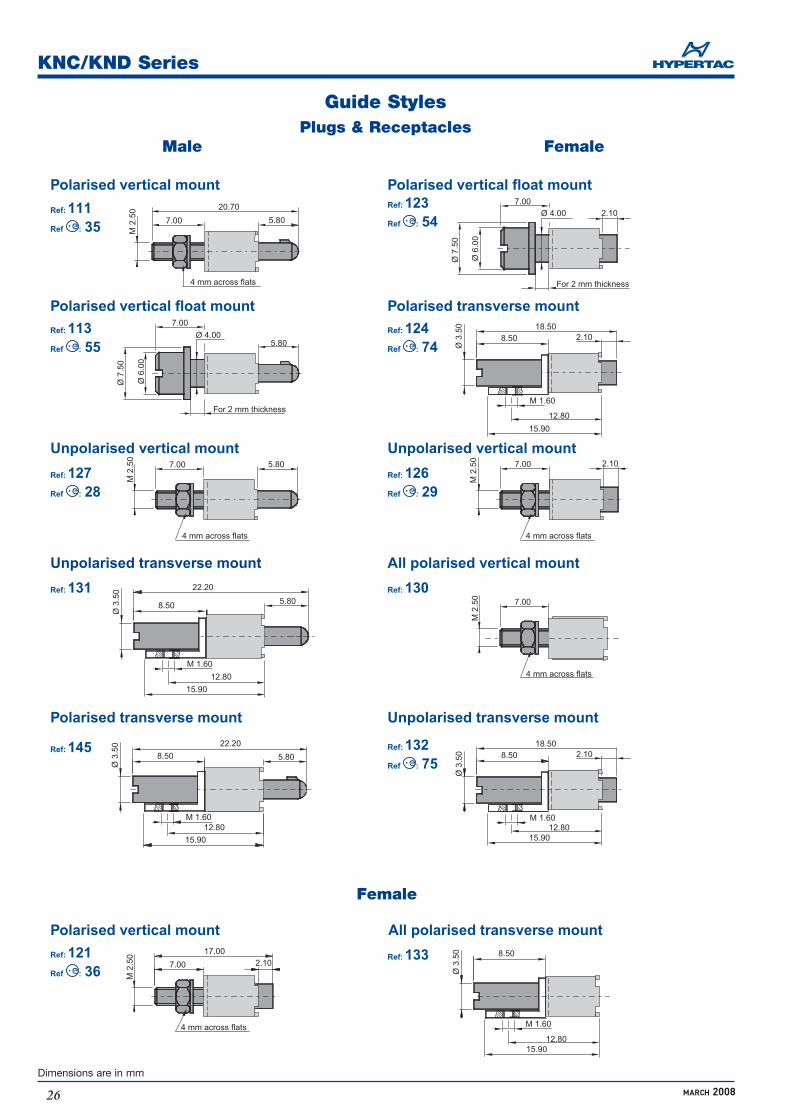
12.80
2.10Ref: 124Ref : 74
Polarised transverse mount
15.90
M 1.60
Ø 3
.50
8.5018.50
12.80
2.10
15.90
M 1.60
Ø 3
.50 8.50
18.50
12.8015.90
M 1.60
Ø 3
.50 8.50
Ref: 132Ref : 75
Unpolarised transverse mount
Ref: 133All polarised transverse mount
7.0020.70
M 2
.50
5.80
4 mm across flats
Ref: 111Ref : 35
Polarised vertical mount
7.0017.00
M 2
.50
2.10
4 mm across flats
Ref: 121Ref : 36
Polarised vertical mount
12.80
5.8022.20
15.90
M 1.60
Ø 3
.50
8.50Ref: 145
Polarised transverse mount
12.80
5.80Ref: 131Unpolarised transverse mount
15.90
M 1.60
Ø 3
.50
8.50
22.20
7.00
Ø 7
.50
For 2 mm thickness
Ø 6
.00
Ø 4.005.80
Ref: 113Ref : 55
Polarised vertical float mount
7.00
M 2
.50
5.80
4 mm across flats
Ref: 127Ref : 28
Unpolarised vertical mount
7.00
Ø 7
.50
Ø 6
.00
2.10Ø 4.00
For 2 mm thickness
Ref: 123Ref : 54
Polarised vertical float mount
7.00M
2.5
0 2.10
4 mm across flats
Ref: 126Ref : 29
Unpolarised vertical mount
7.00
M 2
.50
4 mm across flats
Ref: 130All polarised vertical mount
KNC/KND Series
MARCH 2008
Dimensions are in mm
26
Female
Guide StylesPlugs & Receptacles
Male Female

KNC/KND Series
27MARCH 2008
Dimensions are in mm
Ref: 190Ref: 191
Power or mass vertical mount Power or mass vertical mount
Ref: 10 110Ref : 34
Polarised transverse mount
3.90 5.80
4 mm across flats
Ø 2.50
3.65
Max
.2.
451.
25
4.50
M 2
.50
Ø 3
.70
Ø 2
.00 2.10
4 mm across flats
Ref: 10 125Ref : 27
Unpolarised transverse mount
3.90 5.80
4 mm across flats
Ø 2.50
3.65
Max
.2.
451.
25
Ø 2
.50
4.00 3.90 5.80
4 mm across flats
3.65
Max
.2.
451.
25
Ø 2.50
PCB thickness 1.60 PCB thickness 1.60
PCB thickness 1.60
Plugs & Receptacles
Male Female
Guide StylesMale Plugs only

KNC/KND Series
MARCH 200828
R
P
R
P
R
P
R
P
R
P
R
P
R
P
232 219 215 212 208 204 202
201
203
205
207
231
211
290
PRPRPRPRPRPRPR
210
PR
Plug
Receptacle
Mou
ldin
g
Plu
g
Rec
epta
cle
MouldingFemale locking devices
Mal
e lo
ckin
gd
evic
es
Compatible
Locking DevicesCompatibility Chart

KNC/KND Series
29MARCH 2008
Dimensions are in mm
Male Locking StylesPlugs & Receptacles
Ref: 201
Ref: 207Ref : 47
Jack 1/4 turn lock, free connector
Jackscrew, free connector
Ref: 211Ref : 51
Jackscrew, free connector
0.40
Ø 6
.40
Max
.
5.20 15.00
Ø 2
.50
M 2
.50
5.80 11.80
4 m
m a
cros
s fla
ts5 mm across flatsunremovable screw
Ref: 206Jack 1/4 turn lock, transverse mount
0.40
4 mm across flats
5.20 15.00
3.50
Ø 6
.40
Max
.
For 1.60 mm thickness PCB
Ø 2
.50
Ø 2.50
unremovable screw
M 1
.60
0.50
12.50 unlocked 8.50 locked
6.50 Max.
5.50 mm across flats
M 2
.50
M 2
.50
5.80 8.00
4 mm across flats
Ref: 290Ref : 81
Jackscrew, vertical mount
0.45
Ø 4
.00
M 1
.60
6.50
M 3
9.80
5.5 mm across flats
Ref : 46Ref: 231Jackscrew, vertical mount

KNC/KND Series
MARCH 2008
Dimensions are in mm
30
Female Locking StylesPlugs & Receptacles
Ref: 202
Ref: 210
Jack 1/4 turn lock, vertical mount
Jackscrew, free connector
Ref: 215Ref : 53
Jackscrew, vertical mount
Jackscrew, vertical mount
Ref: 209
Jackscrew, transverse mount
Ref: 232Rotating jackscrew
Ref: 219Ref : 80
4.80 7.00
Ø 3
.60
Ø 5
.00
M 3
4.80
Ø 3
.60
3.50
Ø 5
.00
M3
M3
Ø 2.50
5.00 Max.
4.80
Ø 3
.80
M 2
.054.00
4 mm across flats
4 mm across flats
3.80
2.80 7.00
M 2
.50
4 mm across flats
Term.: 10PCB thickness 1.60
Ref : 49
Ref : 50
Jackscrew, transverse mount
Ref: 212
15.9012.80
4.80
Ø 3
.80
Ø 3
.504.50
M 1.60
4.80 4.00
Ø 3
.60
Ø 5
.00
Ø 4
.00
M 3
4.00
5.50 on flatsRetaining pin

KNC/KND Series
31MARCH 2008
Dimensions are in mm
26 to 98 contacts
108 to 160 contacts
Receptacle Mating Side Layout View
26 to 98 Contacts 108 to 160 Contacts
Panel Preparation Details
30.48 45.72
25.90 41.10
A
B min.
26 44 62Nb. ofcontacts 80
60.96 76.20
56.40 71.60
- -C (KNC) 6.00 6.00
98
91.44
86.90
6.00
108
106.68
48.50
-
126
121.92
56.00
-
144
137.16
63.60
-
160
149.86
69.95
6.00
4.73 4.73C (KND) 4.73 4.73 4.73 4.73 4.73 4.73 -
Panel: Female or male, plugs or receptacles Terminations: 40 - 51
Guide Styles: 111 - 121 - (Fixed Mount)Guide Styles: 113 - 123 - 202 (Float Mount)
26 to 98 Contacts
108 to 160 Contacts

KNC/KND Series
MARCH 2008
Dimensions are in mm
32
Daughter Board26 to 98 Contacts 108 to 160 Contacts
Mother Board26 to 98 Contacts 108 to 160 Contacts
Board Preparation Details
30.48 45.72
20.32 35.56
A
B
26 44 62Nb. ofcontacts 80
60.96 76.20
50.80 66.04
17.78 33.02C 48.26 63.50
98
91.44
81.28
78.74
108
106.68
43.18
-
126
121.92
50.80
-
144
137.16
58.42
-
160
149.86
64.77
-
Daughter Board: Female or Male, plugs or receptacles, 90° terminations(1) Guide Styles: 124 (2) Guide Styles: 110 - 206
Mother Board: Female or Male, plugs or receptacles, straight solder terminationsGuide Styles: 111 - 121- 202

KN Series
33MARCH 2008
Dimensions are in mm
Contacts
Reference Part number
KN- ---55 20 --- 0060421-20POFMR 3401017004B
Male FemaleØ
0.90
6.40
18.70
Ø1.
50
Ø1.
30
Ø1.
80
Ø0.
90
4.40
11.80
Ø1.
30
Ø1.
80
7.40
13.80
Ø1.
80
Ø1.
30
Ø0.
90Ø
1.50
Crimp Terminations AWG 22-28 (0.079 - 0.34mm²)
Crimp Terminations AWG 22-28 (0.079 - 0.34mm²)& Sheath Ø1.45
Ø0.
90
4.40
16.70
Ø1.
30
KN- ---13 20 --- 0060421-20ROG
Reference Part Number
KN- ---44 20 --- 0060422-20PJ9FR 3401017015B
KN- ---22 20 --- 0060422-20RG0
Reference Part number
KN- ---55 20 --- 0060631-20ROF
KN- ---13 20 --- 0060631-21ROGReference Part number
KN- ---44 20 --- 0060632-21RJ3
KN- ---22 20 --- 0060632-21RG0

KN Series
MARCH 200834
Tools
0060
421-
20R
OG
0060
422-
20R
G0
0060
631-
21R
OG
0060
632-
21R
G0
Insertion Extraction
SM-0060000001
Alignment Combsfor 90° through board terminations
2 fixing points SP. 006 00 00 0063 fixing points SP. 006 00 00 004
Screwdriver for M3 Nut
208 locking devices215 locking devices S_075
SD-0060000006
Ref: S_102 (M22520/2.01)
Crimp tool & Positioner
Contact part number Crimp tool Gauje AWG Wire cross section Positioner Tool turret Selector position
28 0.079 3ASTRO TOOL 26 0.14 4M22520/2.01 24 0.20 4
22 0.34 SS-0060000001 528 0.079 3
DANIELS 26 0.14 4M22520/2.01 24 0.20 4
22 0.34 5
2 operations 28 0.079 3ASTRO TOOL 26 0.14 4M22520/2.01 24 0.20 4
1st crimp 22 0.34 SS-0060000001 5(lead) 28 0.079 3
DANIELS 26 0.14 4M22520/2.01 24 0.20 4
22 0.34 5
28 0.079 *ASTRO TOOL 26 0.14 6M22520/2.01 24 0.20 7
2nd crimp 22 0.34 SS-0060000002 7(sheath) 28 0.079 *
DANIELS 26 0.14 6M22520/2.01 24 0.20 7
22 0.34 7
1 operation 28 0.079 2
52007 26 0.14 324 0.20 SP717 422 0.34 4

KN Series
35MARCH 2008
Dimensions are in mm
Accessories
1
0.5A (83.82 for mark 33)
A for other marks
2.541.27
2.0
5.0
90°
0.80
0.80
3.20
Use A Ref.
KNB 017 24.13 009KND 026
KNB 029 39.37 015KND 044
KNB 072 46.99 018KND 108
KNB 041 & 084KNC 062 54.61 021KND 062 & 126
Use A Ref.
KNB 096 62.23 024KND 144
KNB 053KNC 080 & 160 69.85 027KND 080
KNB 120 77.47 030
KNB 065KNC 098 83.82 033KND 098
Each part number contains only one header. To equip fully the connector, you have to order 2, 3, 4 or 6 identical headers.Header can fit on contacts or be positionned between rows.
Antistatic Pin Protector
KNB 017 029 041 053 065 072 084 096 120X +/-0,30 25.50 40.70 56 71.20 86.50 48.40 56 63.60 78.80Qty 1 1 1 1 1 2 2 2 2KNC 062 080 098 119 160X +/-0,30 66 81.20 96.40 114.20 155.00Qty 1 1 1 1 1KND 026 044 108 126 144X +/-0,30 35.50 50.70 111.70 127.00 142.20Qty 1 1 1 1 1
X
Pin Protector (extruded polypropylene)
Ordering information
K N - - - - _ 3 0 8B, C number or D of positions
Ordering information
K N B - - - _ 3 1 4Ref


