CannonD-SubminiatureAccessories
D Cannon D-Subminiature Accessories
2www.ittcannon.com
Dimensions shown in mm (inch)Specifications and dimensions subject to change
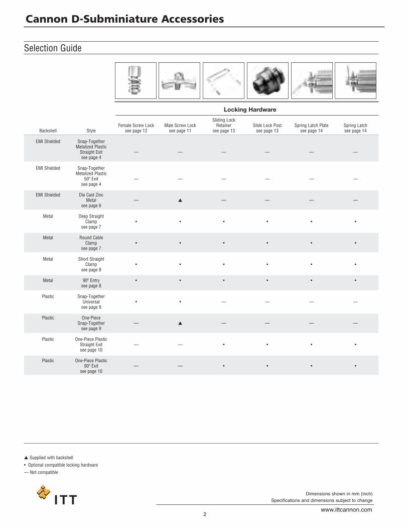
Selection Guide
� Supplied with backshell
• Optional compatible locking hardware
— Not compatible
Locking Hardware
Sliding LockFemale Screw Lock Male Screw Lock Retainer Slide Lock Post Spring Latch Plate Spring Latch
Backshell Style see page 12 see page 11 see page 13 see page 13 see page 14 see page 14
EMI Shielded Snap-TogetherMetalized PlasticStraight Exit — — — — — —see page 4
EMI Shielded Snap-TogetherMetalized Plastic
50º Exit — — — — — —see page 4
EMI Shielded Die Cast ZincMetal — � — — — —
see page 6
Metal Deep StraightClamp • • • • • •
see page 7
Metal Round CableClamp • • • • • •
see page 7
Metal Short StraightClamp • • • • • •
see page 8
Metal 90º Entry • • • • • •see page 8
Plastic Snap-TogetherUniversal • • — — — —see page 9
Plastic One-PieceSnap-Together — � — — — —see page 9
Plastic One-Piece PlasticStraight Exit — — • • • •see page 10
Plastic One-Piece Plastic90º Exit — — • • • •
see page 10

D Cannon D-Subminiature Accessories
3www.ittcannon.com
Dimensions shown in mm (inch)Specifications and dimensions subject to change
Selection Guide
Locking Hardware
Jackpost forJackscrew Assembly Jackpost Assembly Recessed Jackscrew Extended Jackscrew Thumbscrew In-Line Connections
see page 15 see page 15 see page 5 see page 5 see page 5 see page 5
— — • • • •
— — • • • •
— — — — — —
— • — — — —
— • — — — —
— • — — — —
— — — — — —
— — — — — —
— — — — — —
— — — — — —
— — — — — —
D Cannon D-Subminiature Accessories
4www.ittcannon.com
Dimensions shown in mm (inch)Specifications and dimensions subject to change
EMI Shielded Backshell
CABLECLAMP CABLE
GROUNDINGTANG
16,99±0,30(.669±.012)
C
B
D
E
ØHMAX
A
D
E
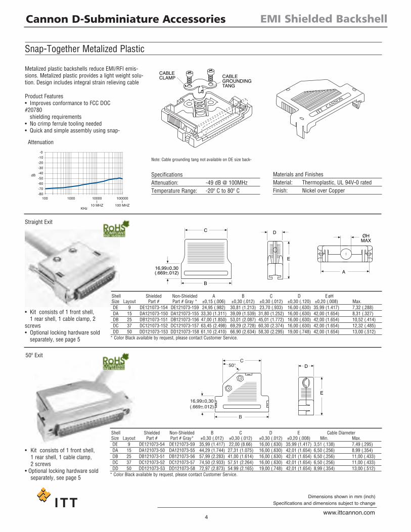
Snap-Together Metalized Plastic
Metalized plastic backshells reduce EMI/RFI emis-sions. Metalized plastic provides a light weight solu-tion. Design includes integral strain relieving cable
Product Features• Improves conformance to FCC DOC#20780shielding requirements
• No crimp ferrule tooling needed• Quick and simple assembly using snap-
Attenuation
Straight Exit
50º Exit
Note: Cable grounding tang not available on DE size back-
SpecificationsAttenuation: -49 dB @ 100MHzTemperature Range: -20º C to 80º C
Shell Shielded Non-Shielded A B C D EøHSize Layout Part # Part # Gray * ±0,15 (.006) ±0,30 (.012) ±0,30 (.012) ±0,30 (.120) ±0,20 (.008) Max.DE 9 DE121073-154 DE121073-159 24,95 (.982) 30,81 (1.213) 23,70 (.933) 16,00 (.630) 35,99 (1.417) 7,32 (.288)DA 15 DA121073-150 DA121073-155 33,30 (1.311) 39,09 (1.539) 31,80 (1.252) 16,00 (.630) 42,00 (1.654) 8,31 (.327)DB 25 DB121073-151 DB121073-156 47,00 (1.850) 53,01 (2.087) 45,01 (1.772) 16,00 (.630) 42,00 (1.654) 10,52 (.414)DC 37 DC121073-152 DC121073-157 63,45 (2.498) 69,29 (2.728) 60,30 (2.374) 16,00 (.630) 42,00 (1.654) 12,32 (.485)DD 50 DD121073-153 DD121073-158 61,10 (2.410) 66,90 (2.634) 58,30 (2.295) 19,00 (.748) 42,00 (1.654) 13,00 (.512)
* Color Black available by request, please contact Customer Service.
Shell Shielded Non-Shielded B C D E Cable DiameterSize Layout Part # Part # Gray* ±0,30 (.012) ±0,30 (.012) ±0,30 (.012) ±0,20 (.008) Min. Max.DE 9 DE121073-54 DE121073-59 35,99 (1.417) 22,00 (8.66) 16,00 (.630) 35,99 (1.417) 3,51 (.138) 7,49 (.295)DA 15 DA121073-50 DA121073-55 44,29 (1.744) 27,31 (1.075) 16,00 (.630) 42,01 (1.654) 6,50 (.256) 8,99 (.354)DB 25 DB121073-51 DB121073-56 57,99 (2.283) 41,00 (1.614) 16,00 (.630) 42,01 (1.654) 6,50 (.256) 11,00 (.433)DC 37 DC121073-52 DC121073-57 74,50 (2.933) 57,51 (2.264) 16,00 (.630) 42,01 (1.654) 6,50 (.256) 11,00 (.433)DD 50 DD121073-53 DD121073-58 72,97 (2.873) 54.99 (2.165) 19,00 (.748) 42,01 (1.654) 8,99 (.354) 13,00 (.512)
* Color Black available by request, please contact Customer Service.
Materials and FinishesMaterial: Thermoplastic, UL 94V-0 ratedFinish: Nickel over Copper
• Kit consists of 1 front shell,1 rear shell, 1 cable clamp, 2
screws• Optional locking hardware soldseparately, see page 5
• Kit consists of 1 front shell,1 rear shell, 1 cable clamp,2 screws
• Optional locking hardware soldseparately, see page 5

D Cannon D-Subminiature Accessories
5www.ittcannon.com
Dimensions shown in mm (inch)Specifications and dimensions subject to change
EMI Shielded Backshell
13,50 (.531)
4,50(.177)DIA.
9,00(.354) #4-40
Threads
6,00(.236)MIN.
19,00 (.748)4,30
(.169) 9,00(.354)
4,10(.161)DIA.
#4-40Threads
50,00 (1.969)4,30 (.169) 9,00 (.354)
6,00 (.236)#4-40THREADS6,00
(.236)MIN.
Locking Hardware for Snap -Together EMI Shielded Backshell
5,00(.197)
5,00(.197)
1,81(.075)
6,00(.236)
4,60(.189)
#4-40 UNC-2B
11,00(.433)
6,00(.236)
4,90 (.193)
3,00 (.118)MIN
#4-40 UNC-2A#4-40 UNC-2B
5,00(.197)
(ACROSS FLATS)
Jackpost for In-Line Connections
Part Number: 250-8501-004Material: BrassFinish: NickelQuantity requiredper connector: 2
Part Number: 250-8501-009 (M3)250-8501-010 (#4-40)
Material: BrassFinish: NickelQuantity requiredper connector: 2
Part Number: 250-8501-013Material: BrassFinish: NickelQuantity requiredper connector: 2
Recessed Jackscrew Extended Jackscrew Thumbscrew
Rectangular Nut Jackpost Jackpost Assembly
Part Number: D121073-19Material: BrassFinish: NickelQuantity requiredper connector: 2
Assembly consists of 1 rectangular nut,1 jackpost, 1 # 4-40 lock washer.

D Cannon D-Subminiature Accessories
6www.ittcannon.com
Dimensions shown in mm (inch)Specifications and dimensions subject to change
EMI Shielded Backshell
B
9 and 15Position
25Position
37 and 50Position
B B
CC
E Dia. E Dia. E Dia.
A
AA
F
D
DD
F F
1
1
1
33
3
5
5
56
4
44
2
2 2
9 and 15 Position* 25 Position* 37 and 50 Position*
Die Cast Zinc Metal Backshell
Die cast metal backshells reduce EMI/RFI emis-sions.Die cast metal backshells offer improved shielding
Compression inserts accommodate a wide varietyof cable sizes.
db
0
-10-20-30-40
-50-60
-70100 1000Mhz
Diecast Shell Shielding Performance
Straight Exit
Product Features• Improves conformance to FCC DOC#20780shielding requirements
• No crimp ferrule tooling needed• Kit consists of 1 front shell, 1 rear shell,2 screws, 2 hex nuts, 2 mounting screws,
2 end brackets, 1 set of compres-
Attenuation
Compression inserts (included with die cast zinc metal backshell)
SpecificationsAttenuation: -50 dB @ 1000MHzTemperature Range: -20º C to 80º C
Position Cable Diameter9,15 4,83/8,89 (.190/.350)25 4,83/11,68 (.190/.460)
37,50 7,62/17,27 (.300/.680)
Shell Part A B C D øE FSize Layout Number ±0,13 (.005) ±0,13 (.005) ±0,13 (.005) ±0,13 (.005) ±0,13 (.005) ±0,13 (.005)DE 9 980-2000-345 31,12 (1.225) 37,21 (1.465) 15,75 (.620) 15,75 (.620) 10,16 (.400) 24,99 (.984)DA 15 980-2000-346 39,12 (1.540) 40,64 (1.600) 15,75 (.620) 15,75 (.620) 10,16 (.400) 33,32 (1.312)DB 25 980-2000-347 53,09 (2.090) 39,37 (1.550) 17,53 (690) 15,75 (.620) 13,34 (.525) 47,17 (1.857)DC 37 980-2000-348 69,34 (2.730) 45,72 (1.800) 21,95 (.864) 15,75 (.620) 18,44 (.726) 63,50 (2.500)DD 50 980-2000-349 66,70 (2.626) 45,72 (1.800) 21,95 (.864) 18,54 (.730) 18,44 (.726) 61,11 (2.406)
#1 #2 #3 #4 #5 #6Position O.D. I.D. O.D. I.D. O.D. I.D. O.D. I.D. O.D. I.D. O.D. I.D.9,15 12,07 (.475) 8,13 (.320) 9,14 (.360) 8,00 (.315) 9,14 (.360) 6,48 (.255) 9,14 (.360) 7,24 (.285) 9,14 (.360) 5,33 (.210) — —25 15,24 (.600) 11,43 (.450) 11,43 (.450) 10,41 (.410) 11.43 (.450) 9,40 (.370) 11.43 (.450) 7,62 (.300) 11.43 (.450) 5,84 (.230) — —
37.50 16,64 (.655) 14,48 (.570) 17,78 (.700) 15,75 (.620) 20,57 (.810) 16,51 (.650) 16,64 (.655) 12,70 (.500) 16,64 (.655) 10,80 (.425) 16,64 (.655) 8,89 (.350)
Materials and FinishesBackshell Material: ZincBackshell Finish: Clear ZincCompression Inserts: PVCHardware Material: SteelHardware Finish: Clear Zinc
* Inserts may be supplied mirror image.
D Cannon D-Subminiature Accessories
7www.ittcannon.com
Dimensions shown in mm (inch)Specifications and dimensions subject to change
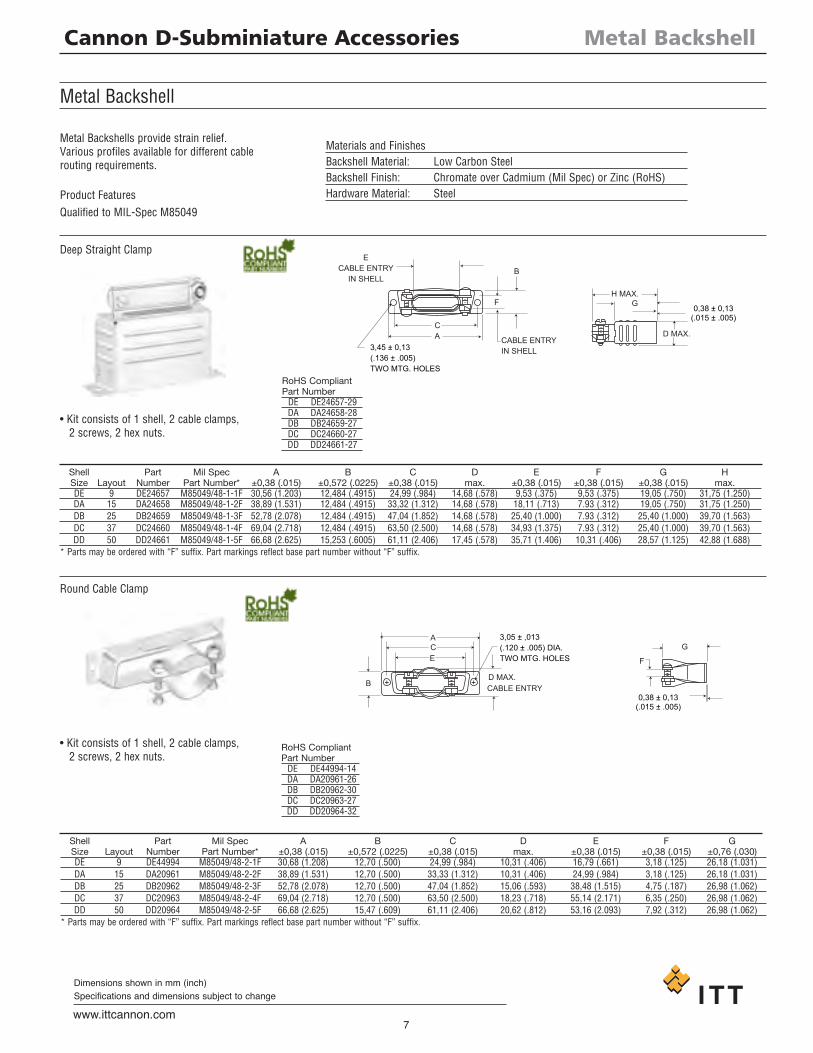
Metal Backshell
CA
ECABLE ENTRY
IN SHELL
CABLE ENTRYIN SHELL
H MAX.G
D MAX.
0,38 ± 0,13(.015 ± .005)
3,45 ± 0,13(.136 ± .005)TWO MTG. HOLES
B
F
+ +
0,38 ± 0,13(.015 ± .005)
F
G
D MAX.
3,05 ± ,013(.120 ± .005) DIA.TWO MTG. HOLES
ACE
BCABLE ENTRY
Metal Backshell
Shell Part Mil Spec A B C D E F G HSize Layout Number Part Number* ±0,38 (.015) ±0,572 (.0225) ±0,38 (.015) max. ±0,38 (.015) ±0,38 (.015) ±0,38 (.015) max.DE 9 DE24657 M85049/48-1-1F 30,56 (1.203) 12,484 (.4915) 24,99 (.984) 14,68 (.578) 9,53 (.375) 9,53 (.375) 19,05 (.750) 31,75 (1.250)DA 15 DA24658 M85049/48-1-2F 38,89 (1.531) 12,484 (.4915) 33,32 (1.312) 14,68 (.578) 18,11 (.713) 7.93 (.312) 19,05 (.750) 31,75 (1.250)DB 25 DB24659 M85049/48-1-3F 52,78 (2.078) 12,484 (.4915) 47,04 (1.852) 14,68 (.578) 25,40 (1.000) 7.93 (.312) 25,40 (1.000) 39,70 (1.563)DC 37 DC24660 M85049/48-1-4F 69,04 (2.718) 12,484 (.4915) 63,50 (2.500) 14,68 (.578) 34,93 (1.375) 7.93 (.312) 25,40 (1.000) 39,70 (1.563)DD 50 DD24661 M85049/48-1-5F 66,68 (2.625) 15,253 (.6005) 61,11 (2.406) 17,45 (.578) 35,71 (1.406) 10,31 (.406) 28,57 (1.125) 42,88 (1.688)
* Parts may be ordered with “F” suffix. Part markings reflect base part number without “F” suffix.
Shell Part Mil Spec A B C D E F GSize Layout Number Part Number* ±0,38 (.015) ±0,572 (.0225) ±0,38 (.015) max. ±0,38 (.015) ±0,38 (.015) ±0,76 (.030)DE 9 DE44994 M85049/48-2-1F 30,68 (1.208) 12,70 (.500) 24,99 (.984) 10,31 (.406) 16,79 (.661) 3,18 (.125) 26,18 (1.031)DA 15 DA20961 M85049/48-2-2F 38,89 (1.531) 12,70 (.500) 33,33 (1.312) 10,31 (.406) 24,99 (.984) 3,18 (.125) 26,18 (1.031)DB 25 DB20962 M85049/48-2-3F 52,78 (2.078) 12,70 (.500) 47,04 (1.852) 15,06 (.593) 38,48 (1.515) 4,75 (.187) 26,98 (1.062)DC 37 DC20963 M85049/48-2-4F 69,04 (2.718) 12,70 (.500) 63,50 (2.500) 18,23 (.718) 55,14 (2.171) 6,35 (.250) 26,98 (1.062)DD 50 DD20964 M85049/48-2-5F 66,68 (2.625) 15,47 (.609) 61,11 (2.406) 20,62 (.812) 53,16 (2.093) 7,92 (.312) 26,98 (1.062)
* Parts may be ordered with “F” suffix. Part markings reflect base part number without “F” suffix.
Metal Backshells provide strain relief.Various profiles available for different cablerouting requirements.
• Kit consists of 1 shell, 2 cable clamps,2 screws, 2 hex nuts.
Deep Straight Clamp
• Kit consists of 1 shell, 2 cable clamps,2 screws, 2 hex nuts.
Round Cable Clamp
Materials and FinishesBackshell Material: Low Carbon SteelBackshell Finish: Chromate over Cadmium (Mil Spec) or Zinc (RoHS)Hardware Material: SteelProduct Features
Qualified to MIL-Spec M85049
RoHS CompliantPart NumberDE DE24657-29DA DA24658-28DB DB24659-27DC DC24660-27DD DD24661-27
RoHS CompliantPart NumberDE DE44994-14DA DA20961-26DB DB20962-30DC DC20963-27DD DD20964-32
D Cannon D-Subminiature Accessories
8www.ittcannon.com
Dimensions shown in mm (inch)Specifications and dimensions subject to change
Metal Backshell
3,05 ± 0,13 (.120 ± .005) DIA.
TWO MTG. HOLES
F(TYP.)
AC B
ECABLEENTRY
0,38 ± 0,13(.015 ± .005)
G
12,30 ± 0,38(.484 ± .015)
B
A
C
#4-40NC-2B THD.TWO MTG. HOLES
ECABLE ENTRY
FCABLEENTRY
2,77 ± 0,25(.109 ± .010)
G
H
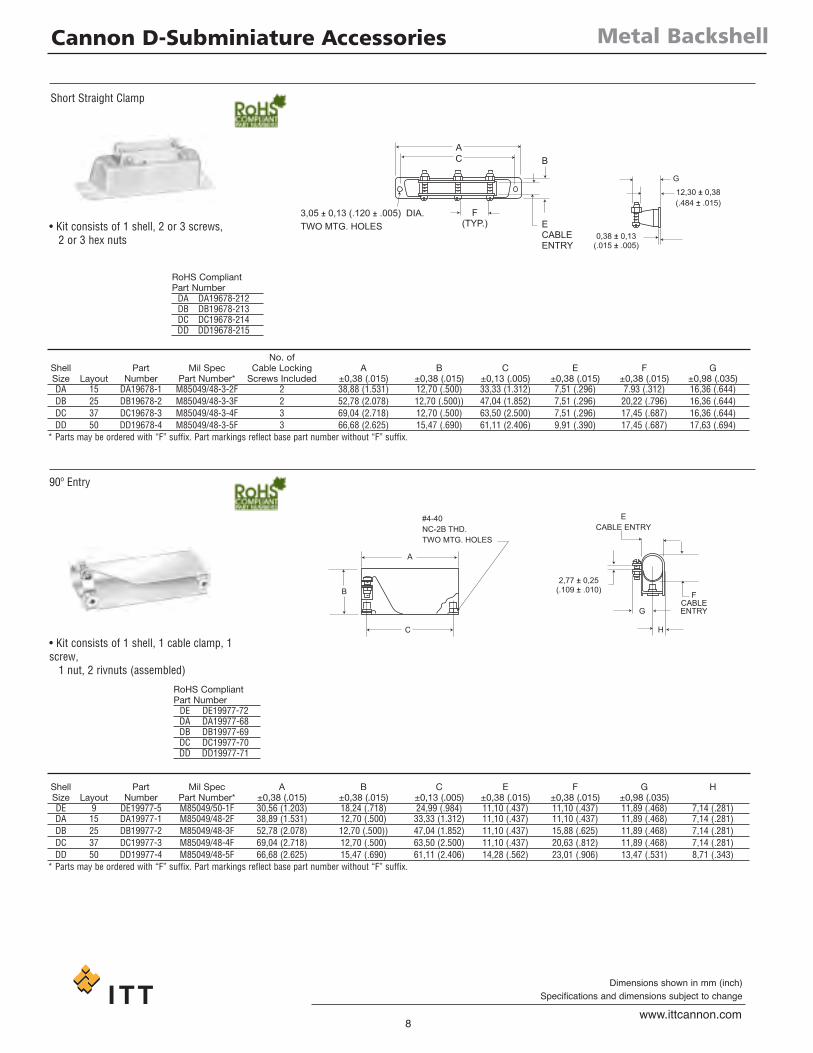
Short Straight Clamp
• Kit consists of 1 shell, 2 or 3 screws,2 or 3 hex nuts
No. ofShell Part Mil Spec Cable Locking A B C E F GSize Layout Number Part Number* Screws Included ±0,38 (.015) ±0,38 (.015) ±0,13 (.005) ±0,38 (.015) ±0,38 (.015) ±0,98 (.035)DA 15 DA19678-1 M85049/48-3-2F 2 38,88 (1.531) 12,70 (.500) 33,33 (1.312) 7,51 (.296) 7.93 (.312) 16,36 (.644)DB 25 DB19678-2 M85049/48-3-3F 2 52,78 (2.078) 12,70 (.500)) 47,04 (1.852) 7,51 (.296) 20,22 (.796) 16,36 (.644)DC 37 DC19678-3 M85049/48-3-4F 3 69,04 (2.718) 12,70 (.500) 63,50 (2.500) 7,51 (.296) 17,45 (.687) 16,36 (.644)DD 50 DD19678-4 M85049/48-3-5F 3 66,68 (2.625) 15,47 (.690) 61,11 (2.406) 9,91 (.390) 17,45 (.687) 17,63 (.694)
* Parts may be ordered with “F” suffix. Part markings reflect base part number without “F” suffix.
90º Entry
• Kit consists of 1 shell, 1 cable clamp, 1screw,1 nut, 2 rivnuts (assembled)
Shell Part Mil Spec A B C E F G HSize Layout Number Part Number* ±0,38 (.015) ±0,38 (.015) ±0,13 (.005) ±0,38 (.015) ±0,38 (.015) ±0,98 (.035)DE 9 DE19977-5 M85049/50-1F 30,56 (1.203) 18,24 (.718) 24,99 (.984) 11,10 (.437) 11,10 (.437) 11,89 (.468) 7,14 (.281)DA 15 DA19977-1 M85049/48-2F 38,89 (1.531) 12,70 (.500) 33,33 (1.312) 11,10 (.437) 11,10 (.437) 11,89 (.468) 7,14 (.281)DB 25 DB19977-2 M85049/48-3F 52,78 (2.078) 12,70 (.500)) 47,04 (1.852) 11,10 (.437) 15,88 (.625) 11,89 (.468) 7,14 (.281)DC 37 DC19977-3 M85049/48-4F 69,04 (2.718) 12,70 (.500) 63,50 (2.500) 11,10 (.437) 20,63 (.812) 11,89 (.468) 7,14 (.281)DD 50 DD19977-4 M85049/48-5F 66,68 (2.625) 15,47 (.690) 61,11 (2.406) 14,28 (.562) 23,01 (.906) 13,47 (.531) 8,71 (.343)
* Parts may be ordered with “F” suffix. Part markings reflect base part number without “F” suffix.
RoHS CompliantPart NumberDA DA19678-212DB DB19678-213DC DC19678-214DD DD19678-215
RoHS CompliantPart NumberDE DE19977-72DA DA19977-68DB DB19977-69DC DC19977-70DD DD19977-71

D Cannon D-Subminiature Accessories
9www.ittcannon.com
Dimensions shown in mm (inch)Specifications and dimensions subject to change
Plastic Backshell
C
B DIA. MAX.CABLE ENTRY
39,50(1.555).
D
42,50(1.673).
+ +
ITT CANNON
A
C
CLAMP,THERMOPLASTIC
CLAMP,METAL
E48,00
(1.890)
D
16,21(.638)
Plastic Backshell
Snap -Together Universal
• 2-piece snap-together design for quickassembly.
• Customer furnishes tie-wrap.
Materials and FinishesMaterial: Black Thermoplastic,
UL 94V-0 rated
• Low cost• Easy to assemble• Mounting hardware included• 2 thumbscrews, 2 cable clamps
Materials and FinishesBackshell Material: PolypropyleneHardware Material: SteelHardware Finish: Black Nickel
Shell Part øB C DSize Layout Number max. ±0,20 (.008) ±0,20 (.008)DE 9 DE115339-20 7,01 (.276) 17,00 (.669) 19,51 (.768)DA 15 DA115339-21 9,60 (.378) 17,00 (.669) 27,79 (1.094)DB 25 DB115339-22 11,61 (.457) 17,00 (.669) 41,61 (1.638)DC 37 DC115339-23 13,00 (.512) 17,00 (.669) 59,99 (2.283)DD 50 DD115339-24 16,00 (.630) 19,81 (.780) 52,32 (2.060)
Note: Part Numbers above replace the following part number series: DE110963-1 to DD110963-5
Shell Part ø DSize Layout Number A C max. EDE 9 DEBS-9 35,20 (1.386) 24,99 (.984) 5,69 (.224) 27,51 (1.083)DA 15 DABS-15 43,31 (1.705) 33,33 (1.312) 5,69 (.224) 31,19 (1.228)DB 25 DBBS-25 57,20 (2.252) 47,04 (1.852) 6,50 (.256) 38,30 (1.508)DC 37 DCBS-37 72,00 (2.83) 62,00 (2.44) 7,80 (.307) 43,08 (1.69)DD 50 DDBS-50 73,70 (2.90) 63,70 (2.50) 8,20 (.322) 48,04 (1.89)
One-Piece Snap-Together
D Cannon D-Subminiature Accessories
10www.ittcannon.com
Dimensions shown in mm (inch)Specifications and dimensions subject to change
Plastic Backshell
TWO SCREWS 4-24 X 5/16 longSELF-TAPPING
B
C A Cable Entry
D
FCable Entry
ø E
GCable Entry
A
C
B
D
J
KCable Entry
ø HCable Entry
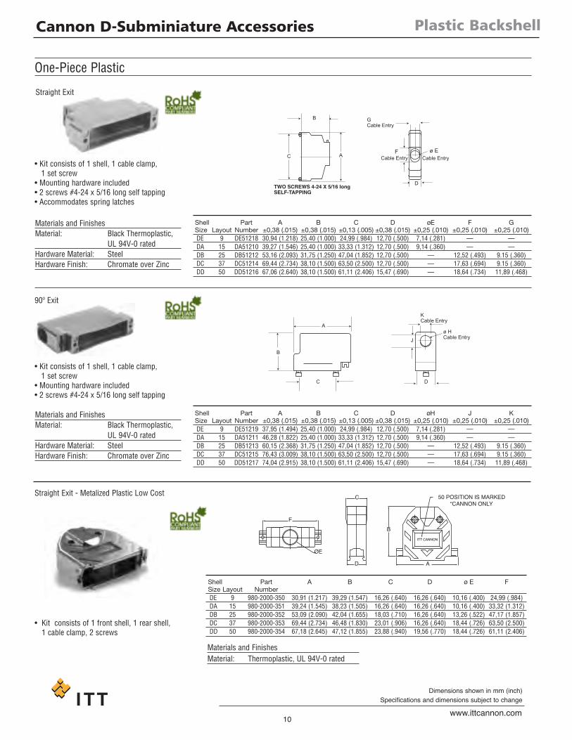
One-Piece Plastic
Straight Exit
90º Exit
• Kit consists of 1 shell, 1 cable clamp,1 set screw
• Mounting hardware included• 2 screws #4-24 x 5/16 long self tapping• Accommodates spring latches
Materials and FinishesMaterial: Black Thermoplastic,
UL 94V-0 ratedHardware Material: SteelHardware Finish: Chromate over Zinc
• Kit consists of 1 shell, 1 cable clamp,1 set screw
• Mounting hardware included• 2 screws #4-24 x 5/16 long self tapping
Materials and FinishesMaterial: Black Thermoplastic,
UL 94V-0 ratedHardware Material: SteelHardware Finish: Chromate over Zinc
Shell Part A B C D øE F GSize Layout Number ±0,38 (.015) ±0,38 (.015) ±0,13 (.005) ±0,38 (.015) ±0,25 (.010) ±0,25 (.010) ±0,25 (.010)DE 9 DE51218 30,94 (1.218) 25,40 (1.000) 24,99 (.984) 12,70 (.500) 7,14 (.281) — —DA 15 DA51210 39,27 (1.546) 25,40 (1.000) 33,33 (1.312) 12,70 (.500) 9,14 (.360) — —DB 25 DB51212 53,16 (2.093) 31,75 (1.250) 47,04 (1.852) 12,70 (.500) — 12,52 (.493) 9.15 (.360)DC 37 DC51214 69,44 (2.734) 38,10 (1.500) 63,50 (2.500) 12,70 (.500) — 17,63 (.694) 9.15 (.360)DD 50 DD51216 67,06 (2.640) 38,10 (1.500) 61,11 (2.406) 15,47 (.690) — 18,64 (.734) 11,89 (.468)
Shell Part A B C D øH J KSize Layout Number ±0,38 (.015) ±0,38 (.015) ±0,13 (.005) ±0,38 (.015) ±0,25 (.010) ±0,25 (.010) ±0,25 (.010)DE 9 DE51219 37,95 (1.494) 25,40 (1.000) 24,99 (.984) 12,70 (.500) 7,14 (.281) — —DA 15 DA51211 46,28 (1.822) 25,40 (1.000) 33,33 (1.312) 12,70 (.500) 9,14 (.360) — —DB 25 DB51213 60,15 (2.368) 31,75 (1.250) 47,04 (1.852) 12,70 (.500) — 12,52 (.493) 9.15 (.360)DC 37 DC51215 76,43 (3.009) 38,10 (1.500) 63,50 (2.500) 12,70 (.500) — 17,63 (.694) 9.15 (.360)DD 50 DD51217 74,04 (2.915) 38,10 (1.500) 61,11 (2.406) 15,47 (.690) — 18,64 (.734) 11,89 (.468)
Straight Exit - Metalized Plastic Low Cost
Shell Part A B C D ø E FSize Layout NumberDE 9 980-2000-350 30,91 (1.217) 39,29 (1.547) 16,26 (.640) 16,26 (.640) 10,16 (.400) 24,99 (.984)DA 15 980-2000-351 39,24 (1.545) 38,23 (1.505) 16,26 (.640) 16,26 (.640) 10,16 (.400) 33,32 (1.312)DB 25 980-2000-352 53,09 (2.090) 42,04 (1.655) 18,03 (.710) 16,26 (.640) 13,26 (.522) 47,17 (1.857)DC 37 980-2000-353 69,44 (2.734) 46,48 (1.830) 23,01 (.906) 16,26 (.640) 18,44 (.726) 63,50 (2.500)DD 50 980-2000-354 67,18 (2.645) 47,12 (1.855) 23,88 (.940) 19,56 (.770) 18,44 (.726) 61,11 (2.406)
• Kit consists of 1 front shell, 1 rear shell,1 cable clamp, 2 screws
Materials and FinishesMaterial: Thermoplastic, UL 94V-0 rated
50 POSITION IS MARKED“CANNON ONLY
B
A
ITT CANNON
C
D
ØE
F
D Cannon D-Subminiature Accessories
11www.ittcannon.com
Dimensions shown in mm (inch)Specifications and dimensions subject to change
Locking Hardware
NUTMOUNTINGPANEL
HEX NUT
LOCKWASHER
WASHER
NUT
CLIP WITH THREAD
SCREW
MOUNTING PANEL
D SUBMINATURECONNECTOR
PIN OR SOCKET
HEX NUT
LOCK WASHER
CLIP WITH THREAD
SCREW
D SUBMINATURECONNECTOR
PIN OR SOCKET
D SUBMINATURECONNECTOR
PIN OR SOCKET
WASHER
CCLIP GAP
CLIP
B
SCREW#4-40 UNC-2A THD
A
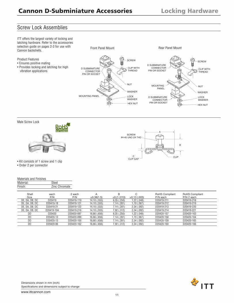
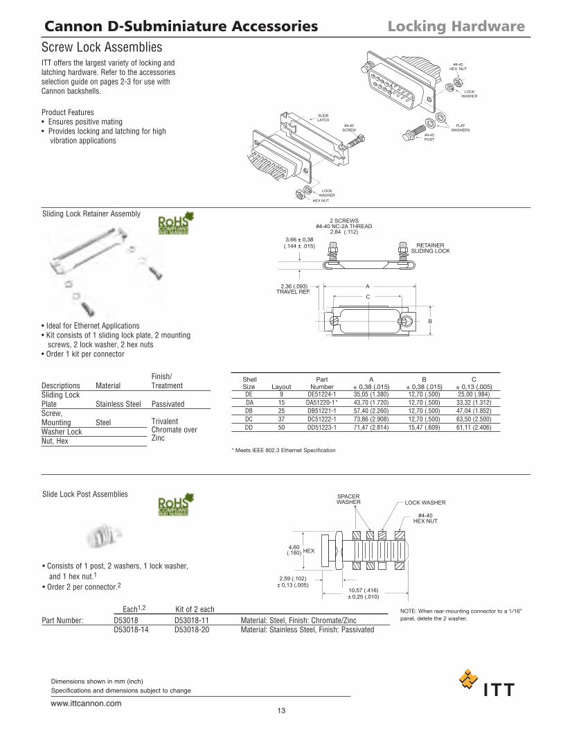
Screw Lock Assemblies
• Kit consists of 1 screw and 1 clip• Order 2 per connector
ITT offers the largest variety of locking andlatching hardware. Refer to the accessoriesselection guide on pages 2-3 for use withCannon backshells.
Product Features• Ensures positive mating• Provides locking and latching for highvibration applications
Materials and FinishesMaterial: SteelFinish: Zinc Chromate
Male Screw Lock
Front Panel Mount Rear Panel Mount
Shell each 2 each A B C RoHS Compliant RoHS CompliantSize P/N P/N ±0,38(1.5) ±0,2 (.010) ±0,13 (.005) P/N each P/N 2 each
DE, DA, DB, DC D20419 D20419-119 14,10 (.555) 6,35 (.250) 1,22 (.048) D20419-211 D20419-218DE, DA, DB, DC D20419-18 D20419-121 14,10 (.555) 7,14 (.281) 1,70 (.067) D20419-212 D20419-219DE, DA, DB, DC D20419-21 D20419-122 14,10 (.555) 7,14 (.281) 2,34 (.092) D20419-213 D20419-220DE, DA, DB, DC D20419-104 D20419-216 14,10 (.555) 7,92 (.312) 2,34 (.092) D20419-214 D20419-221
DD D20420 D20420-097 16,66 (.656) 6,35 (.250) 1,22 (.048) D20420-157 D20420-163DD D20420-13 D20420-099 16,66 (.656) 7,14 (.281) 1,70 (.067) D20420-158 D20420-164DD D20420-15 D20420-100 16,66 (.656) 7,14 (.281) 2,34 (.092) D20420-159 D20420-165DD D20420-86 D20420-162 16,66 (.656) 7,92 (.312) 2,34 (.092) D20420-160 D20420-166
D Cannon D-Subminiature Accessories
12www.ittcannon.com
Dimensions shown in mm (inch)Specifications and dimensions subject to change
4,78 ± 0,38(.188 ± .015)
Hex across Flats
#4-40 NC-2B THD.
6,35 (.250) APPROX.REMOVE ONE WASHERFOR EACH 0,76 (.030)OF PANEL THICKNESSWHEN REAR MOUNTING1,52 (0.60) MAX. PANEL
REAR FLANGE (REF.)
#4-40 NC-2A THD
A4,78 ± 0,38(.188 ± .015)
5,00 (.197) HEX(ACROSS FLATS)
3,50 (.138)MIN4,50
(.177)5,75
(.226)
THD A THD B
3,50(.138)MIN
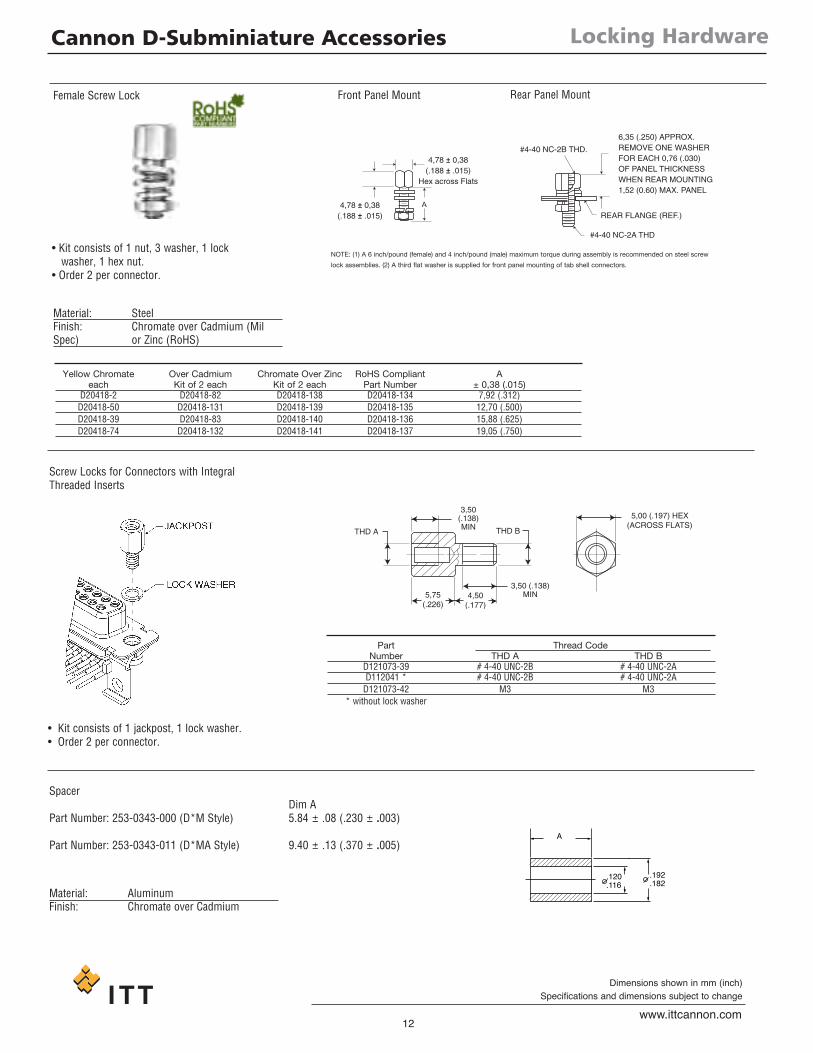
• Kit consists of 1 nut, 3 washer, 1 lockwasher, 1 hex nut.
• Order 2 per connector.
Female Screw Lock Front Panel Mount Rear Panel Mount
NOTE: (1) A 6 inch/pound (female) and 4 inch/pound (male) maximum torque during assembly is recommended on steel screw
lock assemblies. (2) A third flat washer is supplied for front panel mounting of tab shell connectors.
Material: SteelFinish: Chromate over Cadmium (MilSpec) or Zinc (RoHS)
Yellow Chromate Over Cadmium Chromate Over Zinc RoHS Compliant Aeach Kit of 2 each Kit of 2 each Part Number ± 0,38 (.015)
D20418-2 D20418-82 D20418-138 D20418-134 7,92 (.312)D20418-50 D20418-131 D20418-139 D20418-135 12,70 (.500)D20418-39 D20418-83 D20418-140 D20418-136 15,88 (.625)D20418-74 D20418-132 D20418-141 D20418-137 19,05 (.750)
Part Thread CodeNumber THD A THD B
D121073-39 # 4-40 UNC-2B # 4-40 UNC-2AD112041 * # 4-40 UNC-2B # 4-40 UNC-2AD121073-42 M3 M3
* without lock washer
Screw Locks for Connectors with IntegralThreaded Inserts
• Kit consists of 1 jackpost, 1 lock washer.• Order 2 per connector.
Locking Hardware
.120
.116.192.182
A
SpacerDim A
Part Number: 253-0343-000 (D*M Style) 5.84 ± .08 (.230 ± .003)
Part Number: 253-0343-011 (D*MA Style) 9.40 ± .13 (.370 ± .005)
Material: AluminumFinish: Chromate over Cadmium
D Cannon D-Subminiature Accessories
13www.ittcannon.com
Dimensions shown in mm (inch)Specifications and dimensions subject to change
Locking Hardware
LOCKWASHER
SLIDELATCH
#4-40SCREW
#4-40POST
FLATWASHERS
LOCKWASHER
#4-40HEX. NUT
HEX NUT
2 SCREWS#4-40 NC-2A THREAD
2,84 (.112)3,66 ± 0,38
(.144 ± .015)
2,36 (.093)TRAVEL REF.
A
C
B
RETAINERSLIDING LOCK
Screw Lock AssembliesITT offers the largest variety of locking andlatching hardware. Refer to the accessoriesselection guide on pages 2-3 for use withCannon backshells.
Product Features• Ensures positive mating• Provides locking and latching for high
vibration applications
• Ideal for Ethernet Applications• Kit consists of 1 sliding lock plate, 2 mountingscrews, 2 lock washer, 2 hex nuts
• Order 1 kit per connector
Sliding Lock Retainer Assembly
Finish/Descriptions Material TreatmentSliding LockPlate Stainless Steel PassivatedScrew,Mounting SteelWasher LockNut, Hex
Shell Part A B CSize Layout Number ± 0,38 (.015) ± 0,38 (.015) ± 0,13 (.005)DE 9 DE51224-1 35,05 (1.380) 12,70 (.500) 25,00 (.984)DA 15 DA51220-1* 43,70 (1.720) 12,70 (.500) 33,32 (1.312)DB 25 DB51221-1 57,40 (2.260) 12,70 (.500) 47,04 (1.852)DC 37 DC51222-1 73,86 (2.908) 12,70 (.500) 63,50 (2.500)DD 50 DD51223-1 71,47 (2.814) 15,47 (.609) 61,11 (2.406)
* Meets IEEE 802.3 Ethernet Specification
TrivalentChromate overZinc
SPACERWASHER LOCK WASHER
#4-40HEX NUT
HEX
2,59 (.102)± 0,13 (.005)
10,57 (.416)± 0,25 (.010)
4,60(.180)
Slide Lock Post Assemblies
• Consists of 1 post, 2 washers, 1 lock washer,and 1 hex nut.1
• Order 2 per connector.2
NOTE: When rear-mounting connector to a 1/16”panel, delete the 2 washer.Part Number: D53018 D53018-11 Material: Steel, Finish: Chromate/Zinc
D53018-14 D53018-20 Material: Stainless Steel, Finish: Passivated
Each1,2 Kit of 2 each
D Cannon D-Subminiature Accessories
14www.ittcannon.com
Dimensions shown in mm (inch)Specifications and dimensions subject to change
Locking Hardware
15,37 ± 0,64(.605 ± .025)
#4-40 THD. x 7,92 (.312)LONG SCREW
#4-40 HEX. NUT
2,41 (.095) -1,52 (.060)
#4-40SCREW
LATCH PLATE
CONNECTOREITHER PIN OR SOCKET
LOCK WASHER
#4-40HEX NUT
AB
B A
15,57 ± 0,64
(.613 ± .025)#4-40 THD. x 7,92 (.312)LONG SCREW
*2,41 (.095)- 1,52 (.060) #4-40 HEX. NUT
C
#4-40SCREW
SPRING LATCHMOUNTING BRACKET
CONNECTOREITHER PIN OR SOCKET
LOCK WASHER
#4-40HEX. NUT
SPRING LATCH
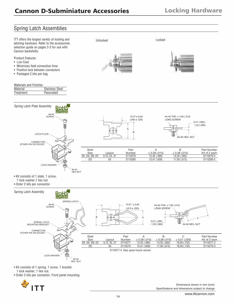
Unlocked Locked
Spring Latch Plate Assembly
Spring Latch Assembly
Spring Latch Assemblies
Materials and FinishesMaterial: Stainless SteelTreatment: Passivated
ITT offers the largest variety of locking andlatching hardware. Refer to the accessoriesselection guide on pages 2-3 for use withCannon backshells.
• Kit consists of 1 plate, 1 screw,1 lock washer,1 hex nut.
• Order 2 kits per connector.
• Kit consists of 1 spring, 1 screw, 1 bracket,1 lock washer, 1 hex nut.
• Order 2 kits per connector. Front panel mounting.
Product Features• Low Cost• Minimizes field connection time• Positive lock between connectors• Packaged 2 kits per bag
Shell Part A B Part NumberSize Layout Number ± 0,38 (.015) ± 0,38 (.015) Kit of 2 each
DE, DA, DB, DC 9,15, 25, 37 D110278 12,42 (.489) 14,35 (.565) D110278-4DD 50 D110280 15,47 (.609) 17,09 (.673) D110280-3
Shell Part A B C Part NumberSize Layout Number ± 0,38 (.015) ± 0,38 (.015) ± 0,51 (.020) Kit of 2 each
DE, DA, DB, DC 9,15, 25, 37 D110277 12,42 (.489) 14,35 (.565) 18,59 (.732) D110277-2DD 50 D110279 15,47 (.609) 17,09 (.673) 18,59 (.732) D110279-3
D110277-4 Rear panel mount version
D Cannon D-Subminiature Accessories
15www.ittcannon.com
Dimensions shown in mm (inch)Specifications and dimensions subject to change
Locking Hardware
4,75 (.187) HEX(ACROSS FLATS)
CONNECTORASSY
#4-40 UNC THREAD
5,84 (.230) ± 0,13 (.005)
14,10 (.555)± 0,13 (.005)
5,59 (.220) MIN.PERFECT THD.
1,14 (.045) ± 0,13 (.005)
PANEL 3,18 (.125) MAX.
LOCK WASHER
HEX NUT
#4-40 UNC THREAD
#4-40 UNCTHREAD 5,59 (.220) DIA.
MAX.
0,64 (.025)± 0,13 (.005)
4,57 (.180)MAX.
16,26 (.640)MAX.
1,73 (.068)MAX.
9,40 (.370)MAX.
5,59 (.220)DIA. MAX.
0,89 (.035) ± 0,13 (.005)
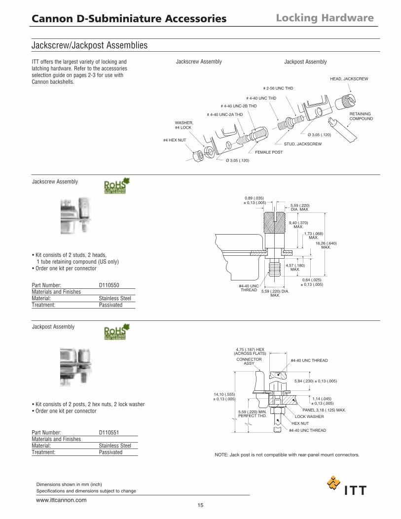
Jackscrew/Jackpost Assemblies
Part Number: D110550Materials and FinishesMaterial: Stainless SteelTreatment: Passivated
• Kit consists of 2 studs, 2 heads,1 tube retaining compound (US only)
• Order one kit per connector
Part Number: D110551Materials and FinishesMaterial: Stainless SteelTreatment: Passivated
• Kit consists of 2 posts, 2 hex nuts, 2 lock washer• Order one kit per connector
Jackpost Assembly
Jackpost Assembly
Jackscrew Assembly
Jackscrew AssemblyITT offers the largest variety of locking andlatching hardware. Refer to the accessoriesselection guide on pages 2-3 for use withCannon backshells.
NOTE: Jack post is not compatible with rear-panel mount connectors.
FEMALE POST
STUD, JACKSCREW
# 2-56 UNC THD
Ø 3,05 (.120)
#4 HEX NUT
WASHER,#4 LOCK
# 4-40 UNC-2A THD
# 4-40 UNC-2B THD
# 4-40 UNC THD
HEAD, JACKSCREW
RETAININGCOMPOUND
Ø 3,05 (.120)

D Cannon D-Subminiature Accessories
16www.ittcannon.com
Dimensions shown in mm (inch)Specifications and dimensions subject to change
Guide Pin Plate
+
+
+ +
+
MOUNTINGPANEL
9,60 (.378)MAX
1,57(.062)6,35 (.250) MAX.
SOLDER POTEXTENSION
A
B
F
E
F
G
C
D4,04 (.159)DIA. MIN.2 PLACES
MOUNTING HOLENO. 4.40 UNC-2B THREAD
(SCREW SUPPORT)2 PLACES
1,60 (.063) ±0,41 ± (.016)
RAD.4 PLACES
+ ++
+
+
4,22 ± 0,05(.166 ± .002)
DIA.2 PLACES
B
E
F
J
H
D
F
KRADIUS
3,66 ± 0,13(.144 ± .005)
DIA.2 PLACES
Shell Part A B C D E F G H J KSize Layout Number ±0,41 (.016) ±0,13 (.005) ±0,13 (.005) ±0,13 (.005) ±0,13 (.005) ±0,13 (.005) ±0,41 (.016) ±0,41 (.016) ±0,41 (.016) ±0,41 (.016)DE 9 DE111920 49,61 (1.953) 40,08 (1.578) 25,00 (.986) 18,65 (.734) 15,27 (.601) 9,52 (.375) 25,40 (1.000) 30,58 (1.204) 12,29 (.484) 6,15 (.242)DA 15 DA22214 57,96 (2.282) 48,41 (1.906) 33,32 (1.312) 22,81 (.898) 19,43 (.765) 9,52 (.375) 25,40 (1.000) 38,91 (1.532) 12,29 (.484) 6,15 (.242)DB 25 DB22254 71,63 (2.820) 62,13 (2.446) 47,04 (1.852) 29,67 (1.168) 26,29 (1.035) 9,52 (.375) 25,40 (1.000) 51,21 (2.016) 11,91 (.469) 5,94 (.234)DC 37 DC22071 88,11 (3.469) 78,59 (3.094) 63,50 (2.500) 37,90 (1.492) 34,52 (1.359) 9,52 (.375) 25,40 (1.000) 67,49 (2.657) 11,91 (.469) 5,94 (.234)DD 50 DD21961 85,72 (3.375) 76,20 (3.000) 61,11 (2.406) 36,50 (1.437) 33,32 (1.312) 11,10 (.437) 28,58 (1.125) 65,10 (2.563) 14,30 (.563) 7,16 (.282)
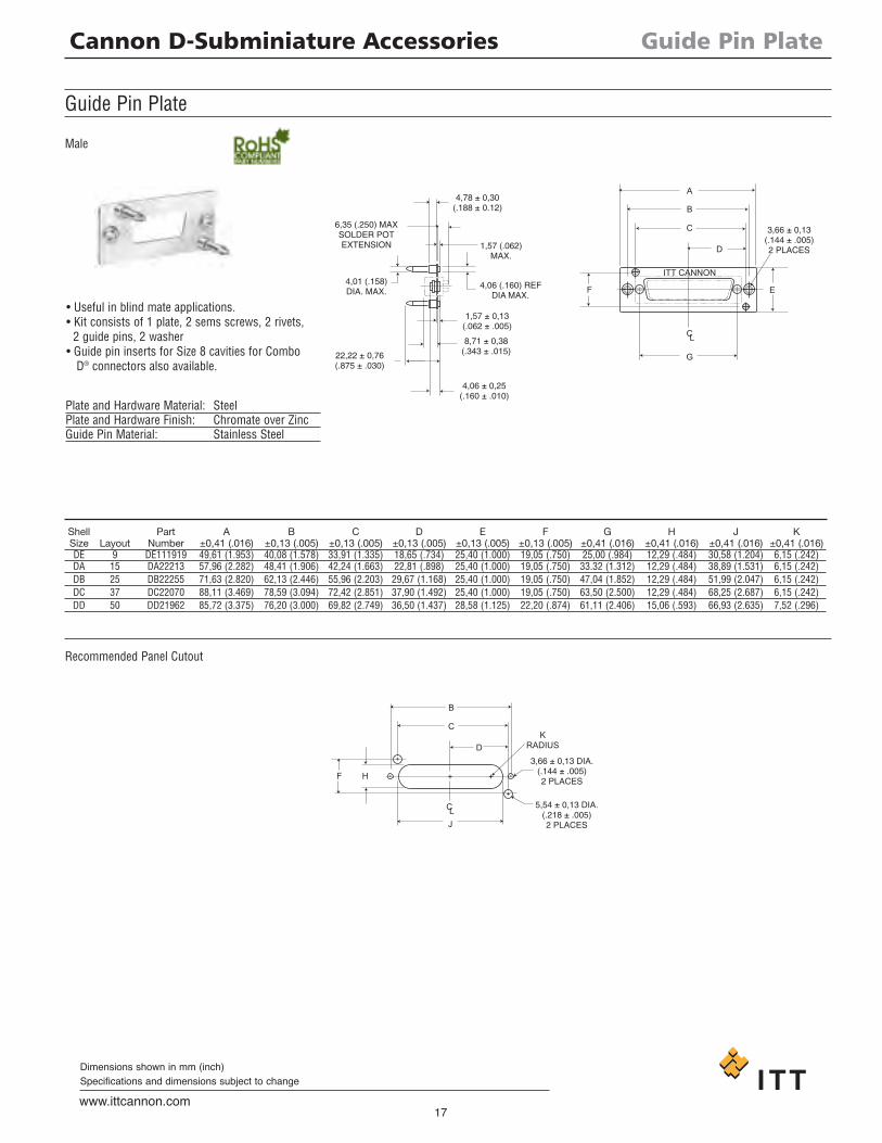
Guide Pin Plate
Female
Recommended Panel Cutout
Plate and Hardware Material: SteelPlate and Hardware Finish: Chromate over Zinc
• Useful in blind mate applications.• Kit consists of 1 plate, 2 screws.• Guide pin inserts for Size 8 cavities forCombo D® connectors also available.
D Cannon D-Subminiature Accessories
17www.ittcannon.com
Dimensions shown in mm (inch)Specifications and dimensions subject to change
Shell Part A B C D E F G H J KSize Layout Number ±0,41 (.016) ±0,13 (.005) ±0,13 (.005) ±0,13 (.005) ±0,13 (.005) ±0,13 (.005) ±0,41 (.016) ±0,41 (.016) ±0,41 (.016) ±0,41 (.016)DE 9 DE111919 49,61 (1.953) 40,08 (1.578) 33,91 (1.335) 18,65 (.734) 25,40 (1.000) 19,05 (.750) 25,00 (.984) 12,29 (.484) 30,58 (1.204) 6,15 (.242)DA 15 DA22213 57,96 (2.282) 48,41 (1.906) 42,24 (1.663) 22,81 (.898) 25,40 (1.000) 19,05 (.750) 33.32 (1.312) 12,29 (.484) 38,89 (1.531) 6,15 (.242)DB 25 DB22255 71,63 (2.820) 62,13 (2.446) 55,96 (2.203) 29,67 (1.168) 25,40 (1.000) 19,05 (.750) 47,04 (1.852) 12,29 (.484) 51,99 (2.047) 6,15 (.242)DC 37 DC22070 88,11 (3.469) 78,59 (3.094) 72,42 (2.851) 37,90 (1.492) 25,40 (1.000) 19,05 (.750) 63,50 (2.500) 12,29 (.484) 68,25 (2.687) 6,15 (.242)DD 50 DD21962 85,72 (3.375) 76,20 (3.000) 69,82 (2.749) 36,50 (1.437) 28,58 (1.125) 22,20 (.874) 61,11 (2.406) 15,06 (.593) 66,93 (2.635) 7,52 (.296)
Guide Pin Plate
4,78 ± 0,30(.188 ± 0.12)
6,35 (.250) MAXSOLDER POTEXTENSION
4,01 (.158)DIA. MAX.
1,57 (.062)MAX.
4,06 (.160) REFDIA MAX.
1,57 ± 0,13(.062 ± .005)
8,71 ± 0,38(.343 ± .015)22,22 ± 0,76
(.875 ± .030)
4,06 ± 0,25(.160 ± .010)
A
B
C
D
ITT CANNON
EF
G
3,66 ± 0,13(.144 ± .005)2 PLACES
CL
+ ++ +
+
+ 3,66 ± 0,13 DIA.(.144 ± .005)2 PLACES
5,54 ± 0,13 DIA.(.218 ± .005)2 PLACES
KRADIUS
B
C
D
J
HF
CL
Recommended Panel Cutout
Guide Pin Plate
Male
Plate and Hardware Material: SteelPlate and Hardware Finish: Chromate over ZincGuide Pin Material: Stainless Steel
• Useful in blind mate applications.• Kit consists of 1 plate, 2 sems screws, 2 rivets,2 guide pins, 2 washer
• Guide pin inserts for Size 8 cavities for ComboD® connectors also available.
D Cannon D-Subminiature Accessories
18www.ittcannon.com
Dimensions shown in mm (inch)Specifications and dimensions subject to change
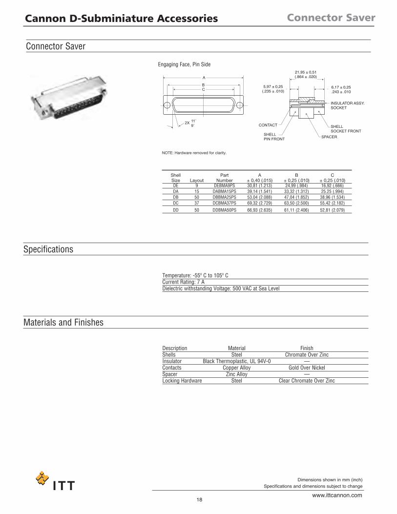
Connector Saver
5,97 ± 0,25(.235 ± .010)
CONTACT
SHELLPIN FRONT SPACER
SHELLSOCKET FRONT
INSULATOR ASSY.SOCKET
6,17 ± 0,25.243 ± .010
21,95 ± 0,51(.864 ± .020)A
BC
2X 11˚9˚
Connector Saver
Specifications
Materials and Finishes
NOTE: Hardware removed for clarity.
Shell Part A B CSize Layout Number ± 0,40 (.015) ± 0,25 (.010) ± 0,25 (.010)DE 9 DEBMA9PS 30,81 (1.213) 24,99 (.984) 16,92 (.666)DA 15 DABMA15PS 39,14 (1.541) 33,32 (1.312) 25.25 (.994)DB 50 DBBMA25PS 53,04 (2.088) 47,04 (1.852) 38,96 (1.534)DC 37 DCBMA37PS 69,32 (2.729) 63,50 (2.500) 55,42 (2.182)DD 50 DDBMA50PS 66,93 (2.635) 61,11 (2.406) 52,81 (2.079)
Temperature: -55º C to 105º CCurrent Rating: 7 ADielectric withstanding Voltage: 500 VAC at Sea Level
Description Material FinishShells Steel Chromate Over ZincInsulator Black Thermoplastic, UL 94V-0 —Contacts Copper Alloy Gold Over NickelSpacer Zinc Alloy —Locking Hardware Steel Clear Chromate Over Zinc
Engaging Face, Pin Side

D Cannon D-Subminiature Accessories
19www.ittcannon.com
Dimensions shown in mm (inch)Specifications and dimensions subject to change
Miscellaneous
RAISED GATE MARKR. TYP.
B
A
B
D
6,35 (.250)
C
1,02.04 WALL TYP.
ITT CANNONXX-XX-XX
10˚ TYP.
0,79 + 0,38 - 0.00
(.031 + .015 - .000)B
A
ø 0,91 +_ 0,18
(.036 +_ .007)
DIA. TYP.
+ +
3,25 (.128) DIA.
4,70 (.185) 0,76 (.030)
15,20(.600)
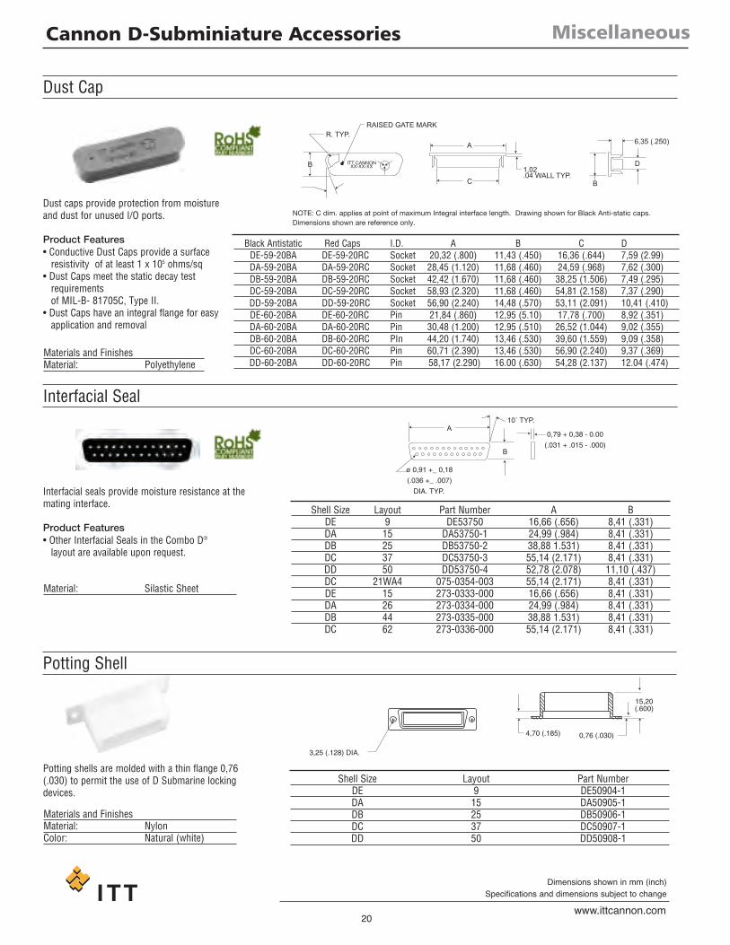
Potting Shell
Black Antistatic Red Caps I.D. A B C DDE-59-20BA DE-59-20RC Socket 20,32 (.800) 11,43 (.450) 16,36 (.644) 7,59 (2.99)DA-59-20BA DA-59-20RC Socket 28,45 (1.120) 11,68 (.460) 24,59 (.968) 7,62 (.300)DB-59-20BA DB-59-20RC Socket 42,42 (1.670) 11,68 (.460) 38,25 (1.506) 7,49 (.295)DC-59-20BA DC-59-20RC Socket 58,93 (2.320) 11,68 (.460) 54,81 (2.158) 7,37 (.290)DD-59-20BA DD-59-20RC Socket 56,90 (2.240) 14,48 (.570) 53,11 (2.091) 10,41 (.410)DE-60-20BA DE-60-20RC Pin 21,84 (.860) 12,95 (5.10) 17,78 (.700) 8,92 (.351)DA-60-20BA DA-60-20RC Pin 30,48 (1.200) 12,95 (.510) 26,52 (1.044) 9,02 (.355)DB-60-20BA DB-60-20RC PIn 44,20 (1.740) 13,46 (.530) 39,60 (1.559) 9,09 (.358)DC-60-20BA DC-60-20RC Pin 60,71 (2.390) 13,46 (.530) 56,90 (2.240) 9,37 (.369)DD-60-20BA DD-60-20RC Pin 58,17 (2.290) 16.00 (.630) 54,28 (2.137) 12.04 (.474)
D Cannon D-Subminiature Accessories
20www.ittcannon.com
Dimensions shown in mm (inch)Specifications and dimensions subject to change
Dust Cap
Interfacial Seal
Dust caps provide protection from moistureand dust for unused I/O ports.
Product Features• Conductive Dust Caps provide a surfaceresistivity of at least 1 x 10⁵ ohms/sq
• Dust Caps meet the static decay testrequirementsof MIL-B- 81705C, Type II.
• Dust Caps have an integral flange for easyapplication and removal
Interfacial seals provide moisture resistance at themating interface.
Product Features• Other Interfacial Seals in the Combo D®
layout are available upon request.
Materials and FinishesMaterial: Polyethylene
Material: Silastic Sheet
Potting shells are molded with a thin flange 0,76(.030) to permit the use of D Submarine lockingdevices.
Materials and FinishesMaterial: NylonColor: Natural (white)
NOTE: C dim. applies at point of maximum Integral interface length. Drawing shown for Black Anti-static caps.Dimensions shown are reference only.
Shell Size Layout Part Number A BDE 9 DE53750 16,66 (.656) 8,41 (.331)DA 15 DA53750-1 24,99 (.984) 8,41 (.331)DB 25 DB53750-2 38,88 1.531) 8,41 (.331)DC 37 DC53750-3 55,14 (2.171) 8,41 (.331)DD 50 DD53750-4 52,78 (2.078) 11,10 (.437)DC 21WA4 075-0354-003 55,14 (2.171) 8,41 (.331)DE 15 273-0333-000 16,66 (.656) 8,41 (.331)DA 26 273-0334-000 24,99 (.984) 8,41 (.331)DB 44 273-0335-000 38,88 1.531) 8,41 (.331)DC 62 273-0336-000 55,14 (2.171) 8,41 (.331)
Shell Size Layout Part NumberDE 9 DE50904-1DA 15 DA50905-1DB 25 DB50906-1DC 37 DC50907-1DD 50 DD50908-1
D Cannon D-Subminiature Accessories
21www.ittcannon.comSpecifications and dimensions subject to change
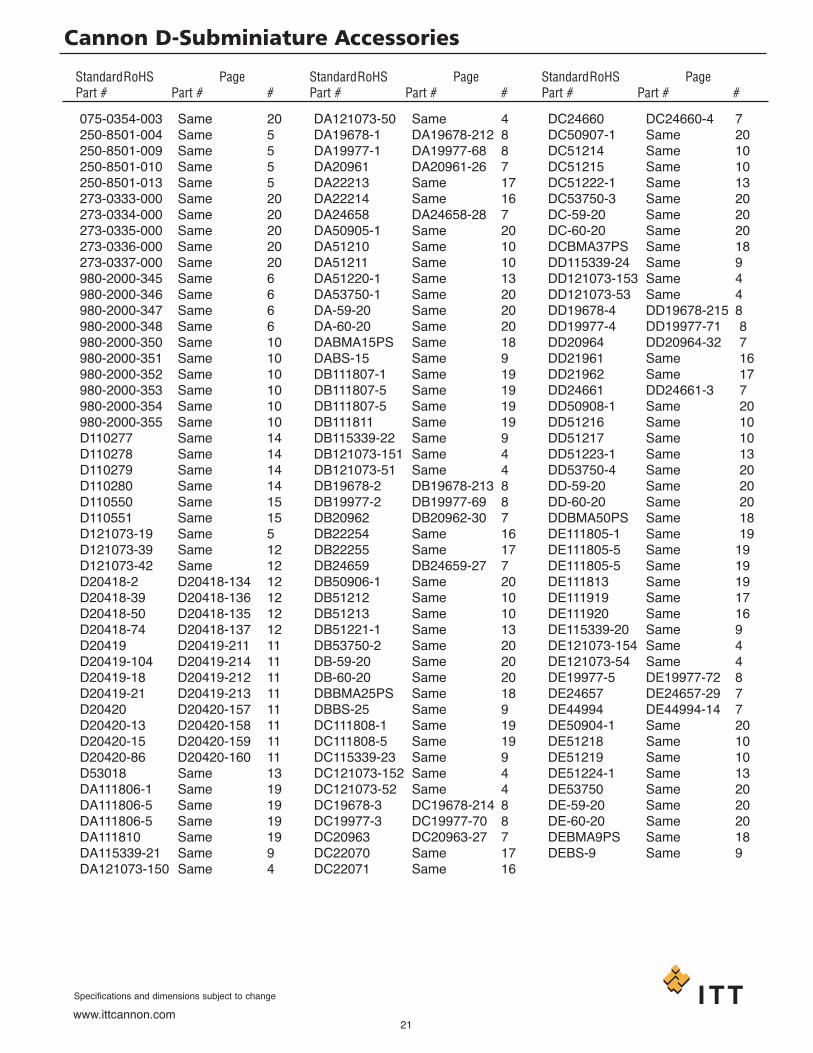
075-0354-003 Same 20250-8501-004 Same 5250-8501-009 Same 5250-8501-010 Same 5250-8501-013 Same 5273-0333-000 Same 20273-0334-000 Same 20273-0335-000 Same 20273-0336-000 Same 20273-0337-000 Same 20980-2000-345 Same 6980-2000-346 Same 6980-2000-347 Same 6980-2000-348 Same 6980-2000-350 Same 10980-2000-351 Same 10980-2000-352 Same 10980-2000-353 Same 10980-2000-354 Same 10980-2000-355 Same 10D110277 Same 14D110278 Same 14D110279 Same 14D110280 Same 14D110550 Same 15D110551 Same 15D121073-19 Same 5D121073-39 Same 12D121073-42 Same 12D20418-2 D20418-134 12D20418-39 D20418-136 12D20418-50 D20418-135 12D20418-74 D20418-137 12D20419 D20419-211 11D20419-104 D20419-214 11D20419-18 D20419-212 11D20419-21 D20419-213 11D20420 D20420-157 11D20420-13 D20420-158 11D20420-15 D20420-159 11D20420-86 D20420-160 11D53018 Same 13DA111806-1 Same 19DA111806-5 Same 19DA111806-5 Same 19DA111810 Same 19DA115339-21 Same 9DA121073-150 Same 4
DA121073-50 Same 4DA19678-1 DA19678-212 8DA19977-1 DA19977-68 8DA20961 DA20961-26 7DA22213 Same 17DA22214 Same 16DA24658 DA24658-28 7DA50905-1 Same 20DA51210 Same 10DA51211 Same 10DA51220-1 Same 13DA53750-1 Same 20DA-59-20 Same 20DA-60-20 Same 20DABMA15PS Same 18DABS-15 Same 9DB111807-1 Same 19DB111807-5 Same 19DB111807-5 Same 19DB111811 Same 19DB115339-22 Same 9DB121073-151 Same 4DB121073-51 Same 4DB19678-2 DB19678-213 8DB19977-2 DB19977-69 8DB20962 DB20962-30 7DB22254 Same 16DB22255 Same 17DB24659 DB24659-27 7DB50906-1 Same 20DB51212 Same 10DB51213 Same 10DB51221-1 Same 13DB53750-2 Same 20DB-59-20 Same 20DB-60-20 Same 20DBBMA25PS Same 18DBBS-25 Same 9DC111808-1 Same 19DC111808-5 Same 19DC115339-23 Same 9DC121073-152 Same 4DC121073-52 Same 4DC19678-3 DC19678-214 8DC19977-3 DC19977-70 8DC20963 DC20963-27 7DC22070 Same 17DC22071 Same 16
DC24660 DC24660-4 7DC50907-1 Same 20DC51214 Same 10DC51215 Same 10DC51222-1 Same 13DC53750-3 Same 20DC-59-20 Same 20DC-60-20 Same 20DCBMA37PS Same 18DD115339-24 Same 9DD121073-153 Same 4DD121073-53 Same 4DD19678-4 DD19678-215 8DD19977-4 DD19977-71 8DD20964 DD20964-32 7DD21961 Same 16DD21962 Same 17DD24661 DD24661-3 7DD50908-1 Same 20DD51216 Same 10DD51217 Same 10DD51223-1 Same 13DD53750-4 Same 20DD-59-20 Same 20DD-60-20 Same 20DDBMA50PS Same 18DE111805-1 Same 19DE111805-5 Same 19DE111805-5 Same 19DE111813 Same 19DE111919 Same 17DE111920 Same 16DE115339-20 Same 9DE121073-154 Same 4DE121073-54 Same 4DE19977-5 DE19977-72 8DE24657 DE24657-29 7DE44994 DE44994-14 7DE50904-1 Same 20DE51218 Same 10DE51219 Same 10DE51224-1 Same 13DE53750 Same 20DE-59-20 Same 20DE-60-20 Same 20DEBMA9PS Same 18DEBS-9 Same 9
StandardRoHS PagePart # Part # #
StandardRoHS PagePart # Part # #
StandardRoHS PagePart # Part # #
D Product Safety Information
22www.ittcannon.com
Specifications and dimensions subject to change
11.. MMAATTEERRIIAALL CCOONNTTEENNTT AANNDD PPHHYYSSIICCAALLFFOORRMMElectrical connectors do not usually containhazardous materials. They contain conduct-ing and non-conducting materials and canbe divided into two groups.a) Printed circuit types and low cost audiotypes which employ all plastic insulators andcasings.b) Rugged, Fire Barrier and High Reliabilitytypes with metal casings and either naturalrubber, synthetic rubber, plastic or glassinsulating materials. Contact materials varywith type of connector and also applicationand are usually manufactured from either:Copper, copper alloys, nickel, alumel,chromel or steel. In special applications,other alloys may be specified.
22.. FFIIRREE CCHHAARRAACCTTEERRIISSTTIICCSS AANNDD EELLEECCTTRRIICCSSHHOOCCKK HHAAZZAARRDDTThheerree iiss nnoo ffiirree hhaazzaarrdd wwhheenn tthhee ccoonnnneecc--ttoorr iiss ccoorrrreeccttllyy wwiirreedd aanndd uusseedd wwiitthhiinn tthheessppeecciiffiieedd ppaarraammeetteerrss.. IInnccoorrrreecctt wwiirriinngg oorraasssseemmbbllyy ooff tthhee ccoonnnneeccttoorr oorr ccaarreelleessss uusseeooff mmeettaall ttoooollss oorr ccoonndduuccttiivvee fflluuiiddss,, oorrttrraannssiitt ddaammaaggee ttoo aannyy ooff tthhee ccoommppoonneennttppaarrttss mmaayy ccaauussee eelleeccttrriicc sshhoocckk oorr bbuurrnnss..LLiivvee cciirrccuuiittss mmuusstt nnoott bbee bbrrookkeenn bbyy sseeppaa--rraattiinngg mmaatteedd ccoonnnneeccttoorrss aass tthhiiss mmaayyccaauussee aarrcciinngg,, iioonniizzaattiioonn aanndd bbuurrnniinngg.. Heatdissipation is greater at maximum resistancein a circuit. Hot spots may occur when resist-ance is raised locally by damage, e.g. crackedor deformed contacts, broken strands ofwire. Local overheating may also result fromthe use of the incorrect application tools orfrom poor quality soldering or slack screwterminals. Overheating may occur if the rat-ings in the product Data Sheet/Catalog areexceeded and can cause breakdown of insu-lation and hence electric shock. If heating isallowed to continue it intensifies by furtherincreasing the local resistance through lossof temper of spring contacts, formation ofoxide film on contacts and wires and leakagecurrents through carbonization of insulationand tracking paths. Fire can then result inthe presence of combustible materials andthis may release noxious fumes. Overheatingmay not be visually apparent. Burns mayresult from touching overheated compo-nents.33.. HHAANNDDLLIINNGGCare must be taken to avoid damage to any component parts of electrical connec-tors during installation and use. Althoughthere are normally no sharp edges, caremust be taken when handling certain com-ponents to avoid injury to fingers. Electricalconnectors may be damaged in transit to thecustomers, and damage may result in cre-ation of hazards. Products should thereforebe examined prior to installation/use andrejected if found to be damaged.
44.. DDIISSPPOOSSAALLIncineration of certain materials may releasenoxious or even toxic fumes.
55.. AAPPPPLLIICCAATTIIOONNConnectors with exposed contacts shouldnot be selected for use on the current supplyside of an electrical circuit, because an elec-tric shock could result from touchingexposed contacts on an unmated connector.Voltages in excess of 30 V ac or 42.5 V dc arepotentially hazardous and care should betaken to ensure that such voltages cannot betransmitted in any way to exposed metalparts of the connector body. The connectorand wiring should be checked, before mak-ing live, to have no damage to metal parts orinsulators, no solder blobs, loose strands,conducting lubricants, swarf, or any otherundesired conducting particles. Circuitresistance and continuity check should bemade to make certain that there are no highresistance joints or spurious conductingpaths. Always use the correct applicationtools as specified in the Data Sheet/Catalog.Do not permit untrained personnel to wire,assemble or tamper with connectors. Foroperation voltage please see appropriatenational regulations.
IIMMPPOORRTTAANNTT GGEENNEERRAALL IINNFFOORRMMAATTIIOONN((ii)) AAiirr aanndd ccrreeeeppaaggee ppaatthhss//OOppeerraattiinngg vvoolltt--aaggee.. The admissible operating voltagesdepend on the individual applications andthe valid national and other applicable safe-ty regulations.For this reason the air and creepage pathdata are only reference values. Observereduction of air and creepage paths due toPC board and/or harnessing.
((iiii)) TTeemmppeerraattuurreeAll information given are temperature limits.The operation temperature depends on theindividual application.
((iiiiii)) OOtthheerr iimmppoorrttaanntt iinnffoorrmmaattiioonnITT continuously endeavors to improve theirproducts. Therefore, Cannon products maydeviate from the description, technical dataand shape as shown in this catalog and datasheets.
“Engineered for life” and “Cannon” areregistered trademarks of ITT Corporation©2007. All data subject to change withoutnotice.
PPRROODDUUCCTT WWAARRRRAANNTTYYITT Electronic Components, a division of ITTCorporation, manufactures the highest qual-ity products available in the marketplace;however these products are intended to beused in accordance with the specifications inthis publication. Any use or application thatdeviates from the stated operating specifica-tions is not recommended and may beunsafe. No information and data containedin this publication shall be construed to cre-ate any liability on the part of ITT. Any newissue of this publication shall automaticallyinvalidate and supersede any and all previ-ous issues. A limited warranty applies toCannon products. Except for obligationsassumed by ITT under this warranty, ITT shallnot be liable for any loss, damage, cost ofrepairs, incidental or consequential damagesof any kind, whether or not based on expressor implied warranty, contract, negligence orstrict liability arising in connection with thedesign, manufacture, sale, use or repair ofthe products. Product availability, prices anddelivery dates are exclusively subject to ourrespective order confirmation form; thesame applies to orders based on develop-ment samples delivered. This publication isnot to be construed as an offer. It is intend-ed merely as an invitation to make an offer.By this publication, ITT does not assumeresponsibility or any liability for any patentinfringements or other rights of third partieswhich may result from its use. Reprintingthis publication is generally permitted, indi-cating the source. However, ITT's prior con-sent must be obtained in all cases.
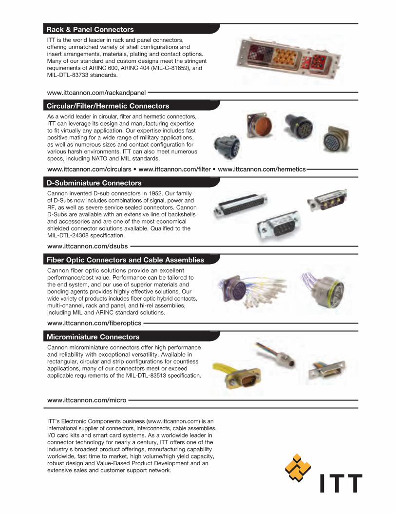
As a world leader in circular, filter and hermetic connectors,ITT can leverage its design and manufacturing expertise to fit virtually any application. Our expertise includes fastpositive mating for a wide range of military applications, as well as numerous sizes and contact configuration forvarious harsh environments. ITT can also meet numerousspecs, including NATO and MIL standards.
ITT's Electronic Components business (www.ittcannon.com) is aninternational supplier of connectors, interconnects, cable assemblies,I/O card kits and smart card systems. As a worldwide leader inconnector technology for nearly a century, ITT offers one of theindustry's broadest product offerings, manufacturing capabilityworldwide, fast time to market, high volume/high yield capacity,robust design and Value-Based Product Development and anextensive sales and customer support network.
Cannon invented D-sub connectors in 1952. Our family of D-Subs now includes combinations of signal, power andRF, as well as severe service sealed connectors. CannonD-Subs are available with an extensive line of backshellsand accessories and are one of the most economicalshielded connector solutions available. Qualified to theMIL-DTL-24308 specification.
Cannon fiber optic solutions provide an excellent performance/cost value. Performance can be tailored tothe end system, and our use of superior materials andbonding agents provides highly effective solutions. Our wide variety of products includes fiber optic hybrid contacts,multi-channel, rack and panel, and hi-rel assemblies,including MIL and ARINC standard solutions.
Cannon microminiature connectors offer high performanceand reliability with exceptional versatility. Available inrectangular, circular and strip configurations for countlessapplications, many of our connectors meet or exceedapplicable requirements of the MIL-DTL-83513 specification.
www.ittcannon.com/circulars • www.ittcannon.com/filter • www.ittcannon.com/hermetics
www.ittcannon.com/dsubs
www.ittcannon.com/fiberoptics
www.ittcannon.com/micro
Circular/Filter/Hermetic Connectors
D-Subminiature Connectors
Microminiature Connectors
Fiber Optic Connectors and Cable Assemblies
ITT is the world leader in rack and panel connectors, offering unmatched variety of shell configurations and insert arrangements, materials, plating and contact options. Many of our standard and custom designs meet the stringentrequirements of ARINC 600, ARINC 404 (MIL-C-81659), andMIL-DTL-83733 standards.
www.ittcannon.com/rackandpanel
Rack & Panel Connectors
Customer Support Locations
ASIA
Tuopandun Industrial Area, Jinda Cheng,Xiner Village, Shajing Town,Baoan District, Shenzhen City,Guangdong, China 518125Tel: +86 755 2726 7238Fax: +86 755 2726 7515
GERMANY
Cannonstrasse 1Weinstadt, 71384Tel: +49.7151.699.0Fax: +49.7151.699.217
ITALY
Corso Europa 41/43Lainate (MI),Italy 20020Tel: +39.02938721Fax: +39.0293872300
UK
Jays Close, Viables EstateBasingstoke, Hants, RG22 4BATel: +44.1256.311200Fax: +44.1256.323356
USA
666 East Dyer RoadSanta Ana, CA 92705Tel: 714.557.4700Fax: 714.628.2142
www.ittcannon.com ©2007 ITT Corporation. “Engineered for life” and “Cannon” are registered trademarks of ITTCorporation. Specification and other data are based on information available at the time ofprinting, and are subject to change without notice.
DSA-sept-07


