
© T
he h
elm
et w
as p
rogr
amm
ed a
nd p
rodu
ced
by D
AISH
IN.
What’s new?
2
General Highlight T-slot feature and feature recognition 3Feature and macro technology 3Tool database 3hyperMILL® SHOP Viewer 3
hyperMILL® MAXX Machining Overview 4
CAM – 3D strategies Highlight 3D-optimised roughing 6
System requirements: Windows® 7 (64-bit), Windows® 8.1 Pro and Windows® 10, DVD-capable driveCAD integrations: hyperCAD®, hyperCAD®-S, Autodesk® Inventor®, SOLIDWORKS, ThinkDesign Software languages: de, en, es, fr, it, nl, cs, pl, ru, sl, pt-br, ja, ko, zh-cn, zh-tw
CAM – 5AXIS strategies Highlight 5AXIS swarf cutting with a curve 65AXIS rework machining 6
hyperCAD®-S: CAD for CAM In a class of its own among CAD systems 7
CAD integration: hyperCAD®-S Highlight hyperCAD®-S Electrode: The electrode module 8 Highlight Positioning 11Chain selection 11Save selection 11Simplify faces 11
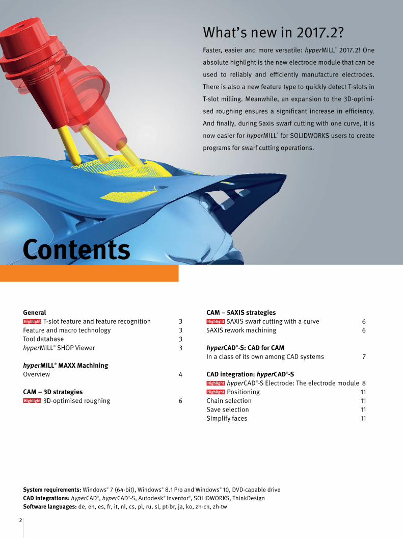
Contents
Faster, easier and more versatile: hyperMILL® 2017.2! One
absolute highlight is the new electrode module that can be
used to reliably and efficiently manufacture electrodes.
There is also a new feature type to quickly detect T-slots in
T-slot milling. Meanwhile, an expansion to the 3D-optimi-
sed roughing ensures a significant increase in efficiency.
And finally, during 5axis swarf cutting with one curve, it is
now easier for hyperMILL® for SOLIDWORKS users to create
programs for swarf cutting operations.
What’s new in 2017.2?

3
General
T-slot feature and feature recognition
The new feature type allows T-slots to be quickly and easily re-cognised in the component. Two types are available for feature recognition: ‘T-slots’ and ‘Pockets with bottom and T-slots’. This feature information is incorporated into the ‘T-slot milling on 3D model’ strategy so that slots can be manufactured in a highly ef-ficient way with just a few clicks.
Benefit: Simple and fast T-slot recognition and programming.
Feature and macro technologies
New functions in the Macro database simplify the programming of multi-axis machining.
n Frame limits and repeated use of macros in several job lists allow multi-axis machining to be controlled very precisely. If frame limits are specified in a job list, the macro takes these into account.
n The direction can be changed when the macro is transferred while machining individual macros.
Benefit: Simplified programming.
Tool database
It is now possible to define factors for axial (ap) and side (ae) in-feeds for holders, NC tools and extensions in the tool database. This allows longer tools to be automatically adjusted to the in-feed in hyperMILL®. Benefit: Improved control of the feedrate value for long NC tools.
hyperMILL® SHOP Viewer
The new ‘Display statistics’ command can be used to quickly ac-cess all important information on machining, such as machining time or number of tool changes. Benefit: Quick overview of machining information.
Highlight
4
Info: hyperMILL® MAXX Machining
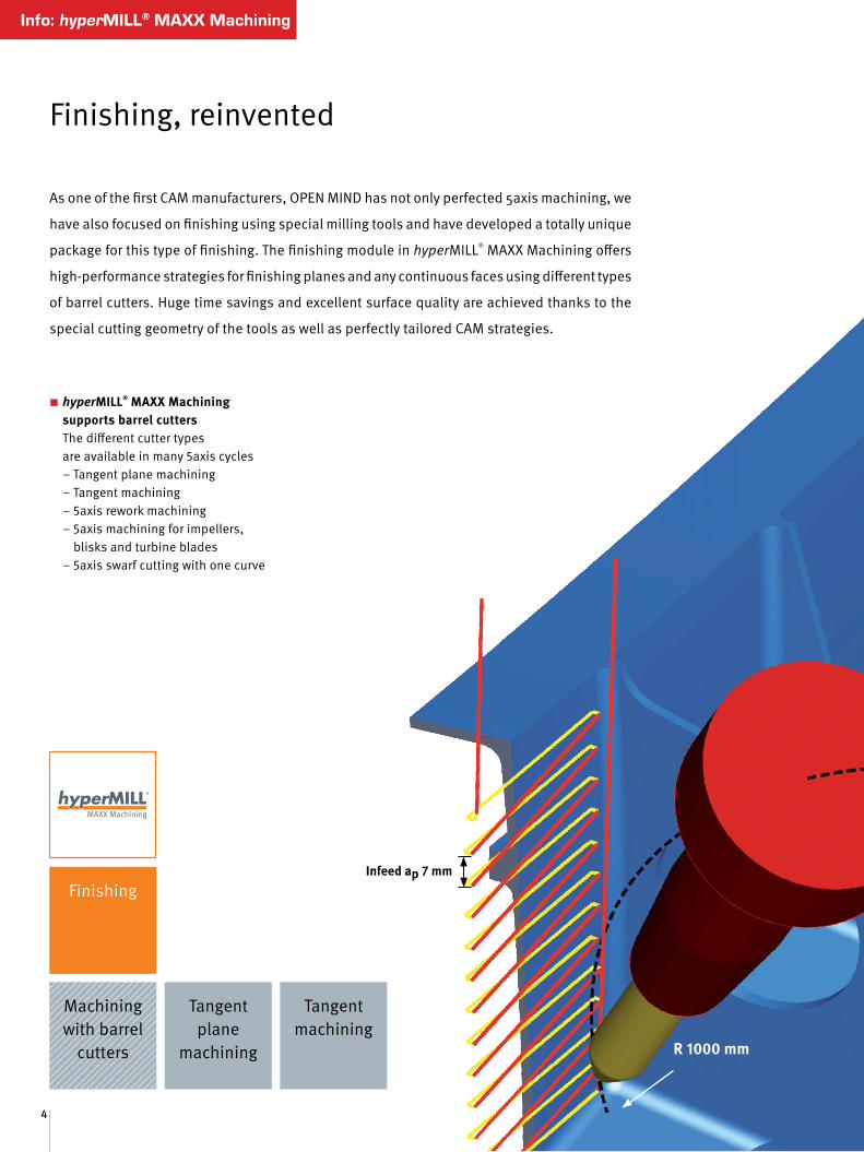
Finishing
Machining with barrel
cutters
Tangent plane
machining
Tangent machining
Infeed ap 7 mm
Finishing, reinvented
As one of the first CAM manufacturers, OPEN MIND has not only perfected 5axis machining, we
have also focused on finishing using special milling tools and have developed a totally unique
package for this type of finishing. The finishing module in hyperMILL® MAXX Machining offers
high-performance strategies for finishing planes and any continuous faces using different types
of barrel cutters. Huge time savings and excellent surface quality are achieved thanks to the
special cutting geometry of the tools as well as perfectly tailored CAM strategies.
R 1000 mm
n hyperMILL® MAXX Machining supports barrel cutters
The different cutter types are available in many 5axis cycles
– Tangent plane machining – Tangent machining – 5axis rework machining – 5axis machining for impellers,
blisks and turbine blades – 5axis swarf cutting with one curve

Barrel cutters Barrel-shaped tools use a section of the circumference, allowing for very large radii. For example, the compact design of the tools allows for a cutting radius of 500 mm.
The conical barrel cutter repre-sents a completely new type of milling tool geometry that was developed by OPENMIND. Thanks to this innovation, faces with minimal curvature can be efficiently machined.
Barrel cutters with a conical angle of less than 40° are
excellent for machining steep areas.
Barrel cutters with a conical angle greater than 50°
are excellent for bottom finishing.
Advantagesn Barrel cutters enable a greater step-over than other cutters
to achieve the same theoretical scallop height
n More efficient production thanks to shorter machining times with the same or better surface quality
n Increases tool life while simultaneously reducing the number of tools required
n Tolerance deviations due to heat distortion at the tool are reduced to a minimum
n The impact of spindle growth on the part quality is reduced.
n Simple tool definition in hyperMILL®
n Full mapping of barrel cutters, even during the simulation
n Barrel cutters with ball mill tips can be simultaneously used as barrel cutters and ball mills
α > 50°α < 40°
n Advantages– Highly efficient– Perfect surfaces– Protects the tool– Simple to program
n Possible applications– Tool and mould making– Production machining– Aerospace– Automotive– Motor sports– Energy industry

6
CAM – 3D strategies
Highlight
Highlight
3D-optimised roughing
The infeed strategy has been optimised for the ‘Rest material roughing’ machining mode. The optimum infeed value is calcula-ted using the ‘Use infeed optimisation’ option in connection with the ‘Additional chip thickness and depth’ values. The user can adjust the machining to the conditions of the tool. This allows tools with long cutting lengths to be optimally exploited and pre-cisely controlled through the ‘Maximum infeed’ parameter.
Benefit: Faster machining and more economic exploitation of the tool.
5axis swarf cutting with one curve
Two new functions ensure greater user-friendliness for hyperMILL® for SOLIDWORKS. A perfect face and an equally perfect curve are created automatically for swarf cutting based on selected geome-tries via a face selection. Automatic filleting for interior corners ensures optimal machining.
Benefit: User-friendly, fast and easy programming.
5axis rework machining
Optimised feedrate adjustment has been implemented in areas without material contact. If the toolpaths are shorter than the defined minimal trimming distance, the feedrate is increased in these areas instead of trimming the toolpath.
Benefit: Fewer retraction movements and consequent time sa-vings for machining.
CAM – 5AXIS strategies
With step optimisationWithout step optimisation
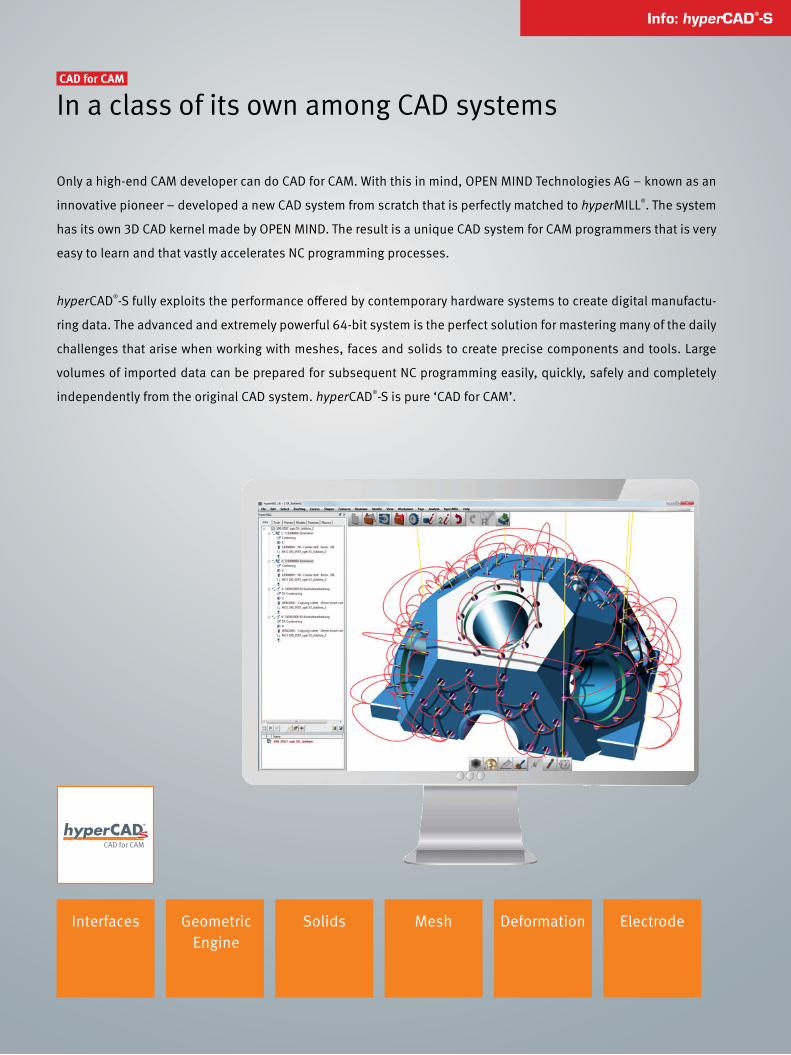
In a class of its own among CAD systems
Only a high-end CAM developer can do CAD for CAM. With this in mind, OPEN MIND Technologies AG – known as an
innovative pioneer – developed a new CAD system from scratch that is perfectly matched to hyperMILL®. The system
has its own 3D CAD kernel made by OPEN MIND. The result is a unique CAD system for CAM programmers that is very
easy to learn and that vastly accelerates NC programming processes.
hyperCAD®-S fully exploits the performance offered by contemporary hardware systems to create digital manufactu-
ring data. The advanced and extremely powerful 64-bit system is the perfect solution for mastering many of the daily
challenges that arise when working with meshes, faces and solids to create precise components and tools. Large
volumes of imported data can be prepared for subsequent NC programming easily, quickly, safely and completely
independently from the original CAD system. hyperCAD®-S is pure ‘CAD for CAM’.
CAD for CAM
Info: hyperCAD®-S
Geometric Engine
Solids Mesh Deformation ElectrodeInterfaces
8
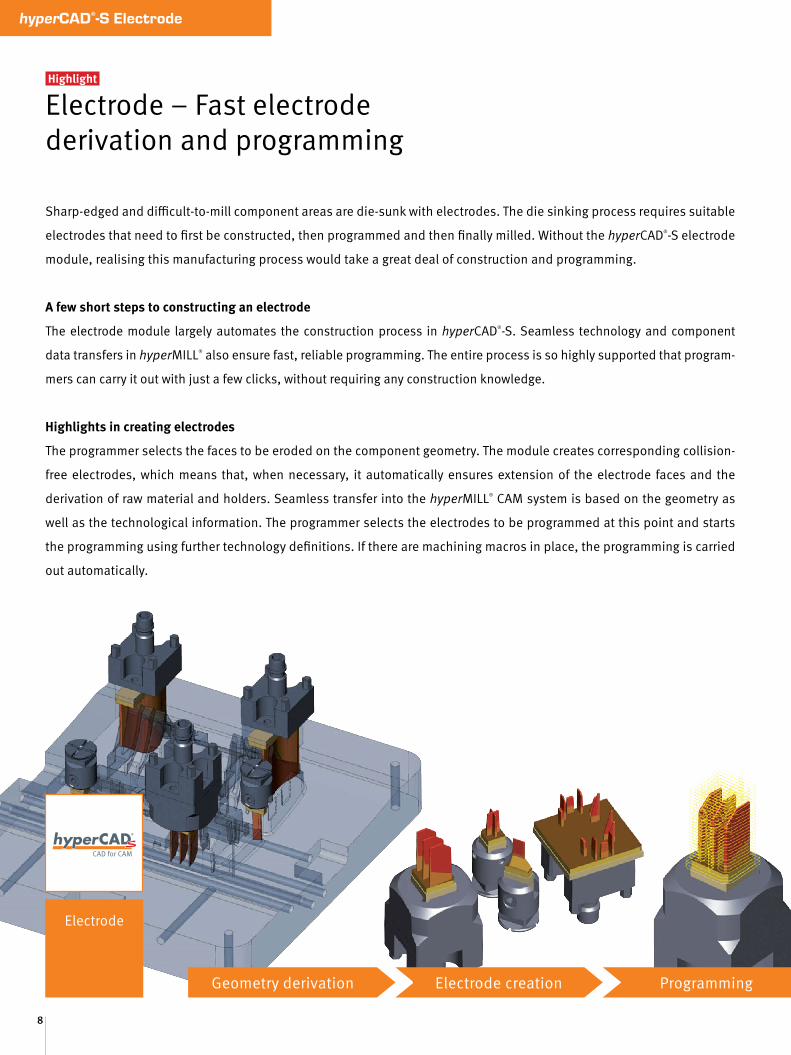
hyperCAD®-S Electrode
Electrode – Fast electrode derivation and programming
Highlight
Sharp-edged and difficult-to-mill component areas are die-sunk with electrodes. The die sinking process requires suitable
electrodes that need to first be constructed, then programmed and then finally milled. Without the hyperCAD®-S electrode
module, realising this manufacturing process would take a great deal of construction and programming.
A few short steps to constructing an electrode
The electrode module largely automates the construction process in hyperCAD®-S. Seamless technology and component
data transfers in hyperMILL® also ensure fast, reliable programming. The entire process is so highly supported that program-
mers can carry it out with just a few clicks, without requiring any construction knowledge.
Highlights in creating electrodes
The programmer selects the faces to be eroded on the component geometry. The module creates corresponding collision-
free electrodes, which means that, when necessary, it automatically ensures extension of the electrode faces and the
derivation of raw material and holders. Seamless transfer into the hyperMILL® CAM system is based on the geometry as
well as the technological information. The programmer selects the electrodes to be programmed at this point and starts
the programming using further technology definitions. If there are machining macros in place, the programming is carried
out automatically.
Electrode
Geometry derivation Electrode creation Programming

Featuresn Suitable for solid and face models
n Geometry selection through face and contour selection
n Automatic extension of electrode geometry
n Holes in the geometry can be automatically closed
n Measuring markers for the electrode
n Automatic colour and layer definition for the individual electrode areas
n Automatic raw material and holder selection with best fit option for optimal alignment
n Automatic stock calculation and collision avoidance
n Electrode reference as chamfer or radius
n Detailed reports
n Incorporation of manually created electrode geometries into the automated process
n Automatic calculation of the minimum rib distance
n Automatic calculation of the length and adjustment options for the length of useless raw material
n Fast programming in hyperMILL®: All technology data, such as the spark gap, stock size and positional reference, are automatically transferred in hyperMILL®. The programming work can even be further automated using machining macros.
Electrode module functions:n Colour coding
User-specific colour information is automatically applied to the geometry areas of the electrode.
n Geometry extension Automatic tangential or linear extension of the electrode geometry. Angle extension is also available for stabilisation.
n Production report A print view with technological information or electrode and raw material reports can be issued for each individual electrode.
Contact face
Erosion face
Tangential extension
Linear extension
Measuring marker
Raw material
Electrode holder
Tangential extension
Linear extension
Milling program EDM
Angle extension
10
hyperCAD®-S Electrode
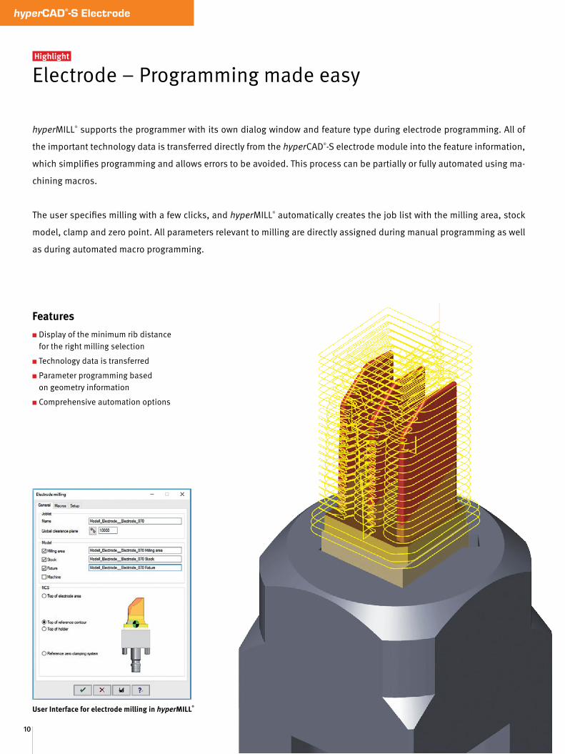
User Interface for electrode milling in hyperMILL®
Electrode – Programming made easy Highlight
hyperMILL® supports the programmer with its own dialog window and feature type during electrode programming. All of
the important technology data is transferred directly from the hyperCAD®-S electrode module into the feature information,
which simplifies programming and allows errors to be avoided. This process can be partially or fully automated using ma-
chining macros.
The user specifies milling with a few clicks, and hyperMILL® automatically creates the job list with the milling area, stock
model, clamp and zero point. All parameters relevant to milling are directly assigned during manual programming as well
as during automated macro programming.
Featuresn Display of the minimum rib distance
for the right milling selection
n Technology data is transferred
n Parameter programming based on geometry information
n Comprehensive automation options
11
CAD-Integration: hyperCAD®-S
Highlight
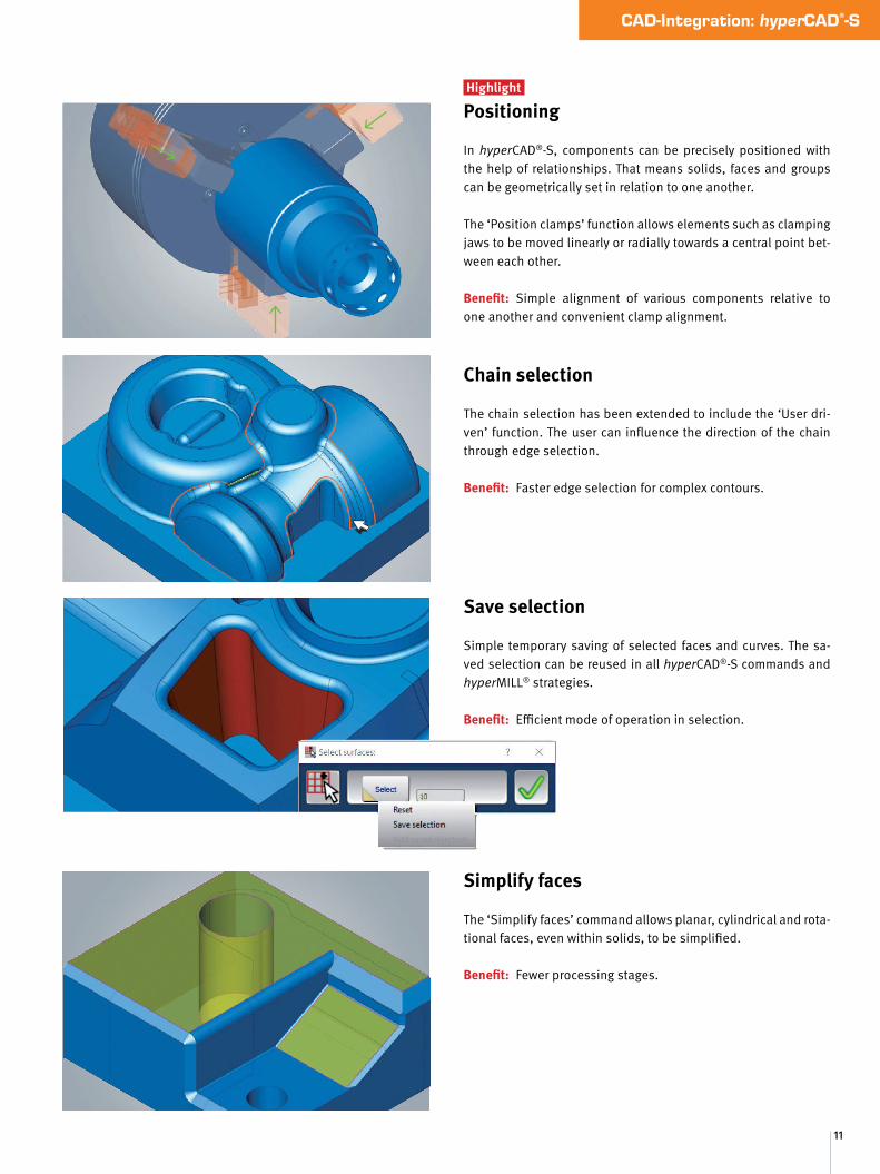
Positioning
In hyperCAD®-S, components can be precisely positioned with the help of relationships. That means solids, faces and groups can be geometrically set in relation to one another.
The ‘Position clamps’ function allows elements such as clamping jaws to be moved linearly or radially towards a central point bet-ween each other.
Benefit: Simple alignment of various components relative to one another and convenient clamp alignment.
Chain selection
The chain selection has been extended to include the ‘User dri-ven’ function. The user can influence the direction of the chain through edge selection.
Benefit: Faster edge selection for complex contours.
Save selection
Simple temporary saving of selected faces and curves. The sa-ved selection can be reused in all hyperCAD®-S commands and hyperMILL® strategies.
Benefit: Efficient mode of operation in selection.
Simplify faces
The ‘Simplify faces’ command allows planar, cylindrical and rota-tional faces, even within solids, to be simplified.
Benefit: Fewer processing stages.

© A
ll rig
hts
rese
rved
, OPE
N M
IND
Tec
hnol
ogie
s AG
, Wes
slin
g, G
erm
any.
Las
t upd
ated
Apr
il 20
17. S
ubje
ct to
mod
ifica
tions
. No
repr
oduc
tion
allo
wed
with
out t
he c
onse
nt o
f the
pub
lishe
r.www.openmind-tech.com
OPEN MIND Technologies AG is representedworldwide with own subsidiaries and through competent partners and is a member of the Mensch und Maschine technology group, www.mum.de
OPEN MIND Technologies AGArgelsrieder Feld 5 • 82234 Wessling • GermanyPhone: +49 8153 933-500E-mail: [email protected]
OPEN MIND Technologies UK Ltd. Units 1 and 2 • Bicester Business Park Telford Road • Bicester • Oxfordshire OX26 4LN • UKPhone: +44 1869 290003E-mail: [email protected]
OPEN MIND Technologies USA, Inc. 1492 Highland Avenue, Unit 3 • Needham MA 02492 • USA Phone: +1 888 516-1232E-mail: [email protected]
OPEN MIND Tecnologia Brasil LTDAAv. Andromeda, 885 SL202106473-000 • Alphaville EmpresarialBarueri • Sao Paulo • BrasilPhone: +55 11 2424 8580E-mail: [email protected]
OPEN MIND Technologies Asia Pacific Pte. Ltd.33 Ubi Avenue 3 #06-32 • Vertex (Tower B) Singapore 408868 • SingaporePhone: +65 6742 95-56E-mail: [email protected]
OPEN MIND Technologies China Co. Ltd.Suite 1608 • Zhong Rong International PlazaNo. 1088 South Pudong RoadShanghai 200120 • China Phone: +86 21 588765-72 E-mail: [email protected]
OPEN MIND CADCAM Technologies India Pvt. Ltd.3C-201, 2nd Floor • 2nd Main Road • Kasturi NagarBangalore 560 043 • Karnataka • India Phone: +91 80 3232 4647E-mail: [email protected]
OPEN MIND Technologies Japan K.K.Misumi Bldg. 3F • 1-17-18, Kichijojihigashicho Musashino-shi • Tokyo 180-0002 • Japan Phone: +81 422 23-5305E-mail: [email protected]
OPEN MIND Technologies Taiwan Inc.3F., No.153, Huanbei Rd., Zhongli Dist. • Taoyuan City 32055Taiwan (R.O.C.)Phone: +886 3 46131-25E-mail: [email protected]
Headquarters
UK
USA
Brazil
Asia Pacific
China
India
Japan
Taiwan


