
Vacuum Valves
Manually OperatedElectropneumatically OperatedElectromagnetically OperatedSpecial ValvesGate Valves
176.01.02Excerpt from the Oerlikon Leybold Vacuum Full Line CatalogProduct Section C14Edition July 2007

C14
Contents
GeneralThe Oerlikon Leybold Vacuum Valve Program . . . . . . . . . . . . . . . . . . . . . . . . . . . . . . . . . . . . . . . . . . . . . C14.03
ProductsSmall Valves of the “micro” RangeOverview . . . . . . . . . . . . . . . . . . . . . . . . . . . . . . . . . . . . . . . . . . . . . . . . . . . . . . . . . . . . . . . . . . . . . . . . . C14.07Right-Angle and Straight-Through Valves, Bellows-Sealed, Various Drives . . . . . . . . . . . . . . . . . . . . . . . C14.08Valves with ISO-KF FlangesOverview . . . . . . . . . . . . . . . . . . . . . . . . . . . . . . . . . . . . . . . . . . . . . . . . . . . . . . . . . . . . . . . . . . . . . . . . . C14.11Nominal Width DN 16 ISO-KF to DN 50 ISO-KFRight-Angle and Straight-Through Valves, Bellows-Sealed, Manually Operated . . . . . . . . . . . . . . . . . . . . C14.12Right-Angle Valves, Bellows-Sealed, Electropneumatically Operated . . . . . . . . . . . . . . . . . . . . . . . . . . . . C14.14Straight-Through Valves, Bellows-Sealed, Electropneumatically Operated . . . . . . . . . . . . . . . . . . . . . . . . C14.16 Right-Angle Valves, Bellows-Sealed, Electromagnetically Operated . . . . . . . . . . . . . . . . . . . . . . . . . . . . . C14.18Valves with ISO-K FlangesOverview . . . . . . . . . . . . . . . . . . . . . . . . . . . . . . . . . . . . . . . . . . . . . . . . . . . . . . . . . . . . . . . . . . . . . . . . . C14.20Nominal Width DN 63 ISO-K to DN 160 ISO-KRight-Angle Valves, Bellows-Sealed, Manually Operated . . . . . . . . . . . . . . . . . . . . . . . . . . . . . . . . . . . . . C14.21 Right-Angle Valves, Bellows-Sealed, Electropneumatically Operated . . . . . . . . . . . . . . . . . . . . . . . . . . . . C14.22Nominal Width DN 250 ISO-K Right-Angle Valves, Bellows-Sealed, Electropneumatically Operated . . . C14.24Special Valves with ISO-KF / ISO-K / CF FlangeOverview . . . . . . . . . . . . . . . . . . . . . . . . . . . . . . . . . . . . . . . . . . . . . . . . . . . . . . . . . . . . . . . . . . . . . . . . . C14.26Nominal Width DN 10 ISO-KF to DN 40 ISO-KF or ISO-KSECUVAC Vacuum Safety Valves . . . . . . . . . . . . . . . . . . . . . . . . . . . . . . . . . . . . . . . . . . . . . . . . . . . . . . C14.27Safety Valve . . . . . . . . . . . . . . . . . . . . . . . . . . . . . . . . . . . . . . . . . . . . . . . . . . . . . . . . . . . . . . . . . . . . . . . C14.30Power Failure Venting Valves, Electromagnetically Actuated . . . . . . . . . . . . . . . . . . . . . . . . . . . . . . . . . . C14.31(Coarse) Variable-Leak Valves with and without Isolation Valve . . . . . . . . . . . . . . . . . . . . . . . . . . . . . . . . C14.32Venting Valves, Various Drives . . . . . . . . . . . . . . . . . . . . . . . . . . . . . . . . . . . . . . . . . . . . . . . . . . . . . . . . . C14.34Vacuum Locks and Sealing Valves . . . . . . . . . . . . . . . . . . . . . . . . . . . . . . . . . . . . . . . . . . . . . . . . . . . . . C14.36Ball Valves . . . . . . . . . . . . . . . . . . . . . . . . . . . . . . . . . . . . . . . . . . . . . . . . . . . . . . . . . . . . . . . . . . . . . . . . C14.38Right-Angle Valve for Mobile Systems according to DOT . . . . . . . . . . . . . . . . . . . . . . . . . . . . . . . . . . . . C14.39Accessories for the Electropneumatically Operated Valves, Valves with ISO-KF / ISO-K Flange . . . . . . . C14.40Special Valves for Turbomolecular Pumps . . . . . . . . . . . . . . . . . . . . . . . . . . . . . . . . . . . . . . . . . . . . . . . . C14.42Nominal Width DN 16 CF to DN 63 CFUHV Valves
All-Metal Right-Angle Valves . . . . . . . . . . . . . . . . . . . . . . . . . . . . . . . . . . . . . . . . . . . . . . . . . . . . . . . . C14.43All-Metal Variable Leak Valves . . . . . . . . . . . . . . . . . . . . . . . . . . . . . . . . . . . . . . . . . . . . . . . . . . . . . . . C14.44
Gate Valves with ISO-KF / CF / ISO-F FlangeOverview . . . . . . . . . . . . . . . . . . . . . . . . . . . . . . . . . . . . . . . . . . . . . . . . . . . . . . . . . . . . . . . . . . . . . . . . . C14.45Miniature UHV Gate Valves, ISO-KF and CF Flange
Manually Operated, . . . . . . . . . . . . . . . . . . . . . . . . . . . . . . . . . . . . . . . . . . . . . . . . . . . . . . . . . . . . . . . C14.46Electropneumatically Operated, . . . . . . . . . . . . . . . . . . . . . . . . . . . . . . . . . . . . . . . . . . . . . . . . . . . . . . C14.50
HV Gate Valves, ISO-F Flange Manually Operated . . . . . . . . . . . . . . . . . . . . . . . . . . . . . . . . . . . . . . . . . . . . . . . . . . . . . . . . . . . . . . . . C14.52Electropneumatically Operated . . . . . . . . . . . . . . . . . . . . . . . . . . . . . . . . . . . . . . . . . . . . . . . . . . . . . . C14.54
UHV Gate Valves, Manually Operated, CF Flange . . . . . . . . . . . . . . . . . . . . . . . . . . . . . . . . . . . . . . . . . . C14.56UHV Gate Valves, Electropneumatically Operated
ISO-F Flange . . . . . . . . . . . . . . . . . . . . . . . . . . . . . . . . . . . . . . . . . . . . . . . . . . . . . . . . . . . . . . . . . . . . C14.58CF Flange . . . . . . . . . . . . . . . . . . . . . . . . . . . . . . . . . . . . . . . . . . . . . . . . . . . . . . . . . . . . . . . . . . . . . . C14.60
02 Oerlikon Leybold Vacuum Full Line Catalog

C1403Oerlikon Leybold Vacuum Full Line Catalog
The Oerlikon Leybold VacuumValve Program
The long-standing experience of Oerlikon Leybold Vacuum in the area ofvacuum engineering is reflected in theselection and the design of the valvesand vacuum protection componentsfor a wide variety of applications. Therange of products is such that a relia-ble solution can be offered for everyvacuum engineering application. Manyyears of service and the reliability of thevalves is ensured by design. OerlikonLeybold Vacuum valves are well-provenin many widely varying areas of rese-arch and industry.
The Design of a Vacuum ValveScope of the Range of Valves
The range of Oerlikon Leybold Vacuumvalves comprises:
- Small valves micro
- Right-angle and straight-throughvalves (no slanted seat valve) witha nominal width of DN 16 to DN 40with ISO-KF flanges
- Right-angle valves with a nominalwidth of DN 63 to DN 250 withISO-K flanges
- Gate valves with a nominal widthof DN 16 to DN 250 with variousflanges
- Ball valves
- Special valves
BellowBellow
Vacuum
Housing
Valve disk withvacuum seal
Valve
Type of -stepped rotary knob-electropneumatic
Valve cover
Housing seal
Vacuum
-electromagnetic
operation:
It is the aim of Oerlikon LeyboldVacuum to meet, through the offeredrange of isolation components and val-ves, the customers requirements re-garding the design of such compo-nents. For this reason all valves areavailable with different driving systems.
With the exception of the special val-ves you may select between a steppedrotary knob manual drive, an electrop-neumatic drive or an electro-magneticdrive system.
Right-angle valves DN 16 ISO-KF to DN 40 ISO-KF as well as DN 63 ISO-Kto DN 160 ISO-K are either availablewith an aluminium or stainless steelbody (the latter up to DN 100 ISO-Konly).
The special characteristics of theapplication in each case result inspecial requirements concerningfeatures of the valves, for example:
- Coating- Short switching cycles
(e.g. 1.5 s)- Very high number of opening
and switching cycles (e.g. over 10 million cycles)
- Analytical engineering- High conductance (similar to
the corresponding flange components, like bends, for example)
- High integral leak tightness for the valves (leak rates below 10-9 mbar l/s)
- Lamps and tubes manufacture- Temperature resistant- Permissible ambient tempera-
tures, 50 °C max.
- Accelerator technology- Materials capable of resisting
radiation, high temperatures and corrosion at the same time
- Metallurgy and furnace manufac-ture- Rugged and insensitive to con-
tamination
- Chemistry- Choice of materials in contact
with the medium for the valve body
All applications have the followingrequirements in common:
- Quiet opening action with very little vibration
- Compact design, low weight
- Highly visible, unambiguous positi-on indicator
- For use within the pressure rangefrom 10-8 to 2500 mbar, if not stated otherwise
- Fully operational within the entirespecified pressure range
Oerlikon Leybold Vacuum valvesmeet these requirements, unlessotherwise stated by the technicaldata.
Quality Assurance
The various markets, like Analytical orCoating, for example are very demand-ing regarding certain important featuresfor the valves which are to be used inthe new generation of instruments cur-rently under development. Demandedare, among other things, high reliabilityduring the entire service life, high inte-gral leak tightness, a high number ofopening/closing cycles as well as afast response.
The valves from Oerlikon LeyboldVacuum meet all these demandingrequirements!
For further information on flangeconnections and flange componentsplease refer to Product Section C13“Vacuum Fittings ISO-KF, ISO-K, ISO-F,CF and Feedthroughs”.
General
C14 04 Oerlikon Leybold Vacuum Full Line Catalog
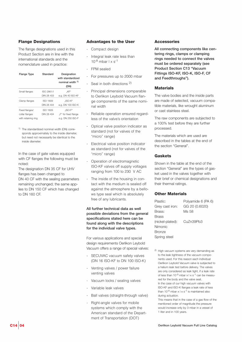
Flange Designations
The flange designations used in thisProduct Section are in line with theinternational standards and thenomenclature used in practice:
1) The standardized nominal width (DN) corre-sponds approximately to the inside diameter, but need not necessarily be identical to the inside diameter.
In the case of gate valves equippedwith CF flanges the following must benoted: The designation DN 35 CF for UHVflanges has been changed to DN 40 CF with the sealing parametersremaining unchanged; the same app-lies to DN 150 CF which has changedto DN 160 CF.
Advantages to the User
- Compact design
- Integral leak rate less than 10-8 mbar l x s-1
- FPM sealed
- For pressures up to 2000 mbar
- Seal in both directions 2)
- Principal dimensions comparableto Oerlikon Leybold Vacuum flan-ge components of the same nomi-nal width
- Reliable operation ensured regard-less of the valve’s orientation
- Optical valve position indicator asstandard (not for valves of the“micro” range)
- Electrical valve position indicatoras standard (not for valves of the“micro” range)
- Operation of electromagnetic ISO-KF valves off supply voltagesranging from 100 to 230 V AC
- The inside of the housing in con-tact with the medium is sealed offagainst the atmosphere by a bello-ws type seal which is absolutelyfree of any lubricants.
All further technical data as wellpossible deviations from the generalspecifications stated here can befound along with the descriptionsfor the individual valve types.
For various applications and specialdesign requirements Oerlikon LeyboldVacuum offers a range of special valves:
- SECUVAC vacuum safety valves (DN 16 ISO-KF to DN 100 ISO-K)
- Venting valves / power failureventing valves
- Vacuum locks / sealing valves
- Variable leak valves
- Ball valves (straight-through valve)
- Right-angle valves for mobilesystems which comply with theAmerican standard of the Depart-ment of Transportation (DOT)
Flange Type Standard Designation
with standardized
nominal width 1)
(DN)
Small flanges ISO 2861/I „KF“
DIN 28 403 e.g. DN 40 ISO-KF
Clamp flanges ISO 1609 „ISO-K“
DIN 28 404 e.g. DN 100 ISO-K
Fixed flanges/ ISO 1609 „ISO-F“
collar flanges DIN 28 404 „F“ for fixed flange
with retaining ring e.g. DN 250 ISO-F
Accessories
All connecting components like cen-tering rings, clamps or clampingrings needed to connect the valvesmust be ordered separately (seeProduct Section C13 “VacuumFittings ISO-KF, ISO-K, ISO-F, CFand Feedthroughs”).
Materials
The valve bodies and the inside partsare made of selected, vacuum compa-tible materials, like wrought aluminumor cast stainless steel.
The raw components are subjected toa 100% test before they are furtherprocessed.
The materials which are used aredescribed in the tables at the end ofthe section “General”.
Gaskets
Shown in the table at the end of thesection “General” are the types of gas-ket used in the valves together withtheir brief or chemical designations andtheir thermal ratings.
Other Materials
Plastic: Polyamide 6 (PA 6)Grey cast iron: GG 20 (0.6020)Brass: Ms 58Brass (nickel-plated): CuZn39Pb3NimonicBronzeSpring steel
2) High vacuum systems are very demanding as to the leak tightness of the vacuum compo-nents used. For this reason each individual Oerlikon Leybold Vacuum valve is subjected to a helium leak test before delivery. The valves are only considered as leak tight, if a leak rate of less than 10-9 mbar x l x s-1 can be measu-red for the body and the valve seat. In the case of our high vacuum valves with ISO-KF and ISO-K flanges a leak rate of less than 10-9 mbar x l x s-1 is maintained also during actuation. This means that in the case of a gas flow of thementioned order of magnitude the pressure would increase only by 3 mbar in a vessel of 1 liter and in 100 years.

C1405Oerlikon Leybold Vacuum Full Line Catalog
Materials
Aluminum Alloys
Material No. Brief Designation
DIN AA DIN
3.0615 – AlMgSiPbF28
3.2153 – G AlSi7Cu3
3.2315 6081 AlMgSi1F28
3.2341 – G AlSi5Mg wa
3.2371 – G AlSi7Mg06
3.2373 – G AlSi9Mg
3.2381 – G AlSi10Mg wa
3.3527 – AlMg2Mn0,8F20
Stainless Steels
Material No. Brief Designation
DIN AISI DIN
1.4034 420 X 46 Cr 13
1.4301 304 X5 CrNi 18 10
1.4305 303 X10 CrNi 51 89
1.4306 304 L X2 CrNi 18 10
1.4308 – G-X6 CrNi 18 1
1.4310 301 X12 CrNi 17 7
1.4404 316 L X2 CrNiMo 17 13 3
1.4435 316 L X2 CrNiMo 18 14 3
1.4541 321 X10 CrNiTi 18 10
1.4571 316 Ti X6 CrNiMoTi 17 12 2
Standard Steels
Material No. Brief Designation
DIN DIN
1.0388 St4/St14
1.0425 H II
Materials used for the Gaskets
Brief Designation Chemical Designation Typical Trade Name Degassing Temperature
FPM Fluor caoutchouc Viton up to 150 °C
NBR Acrylonitrile-butadiene rubber Perbunan up to 080 °C
PTFE Polytetrafluor ethylene Teflon up to 250 °C
EPDM Ethylene-propylenedien caoutchouc – up to 150 °C
Abbreviations used in the valve designations
Brief Designation Valve Type
EMD Solenoid straight-through valve
EME Solenoid right-angle valve
EPD Electropneumatic straight-through valve
EPE Electropneumatic right-angle valve
MAN Manual operation
PD Pneumatic straight-through valve
PE Pneumatic right-angle valve
C14 06 Oerlikon Leybold Vacuum Full Line Catalog
Notes
C1407Oerlikon Leybold Vacuum Full Line Catalog
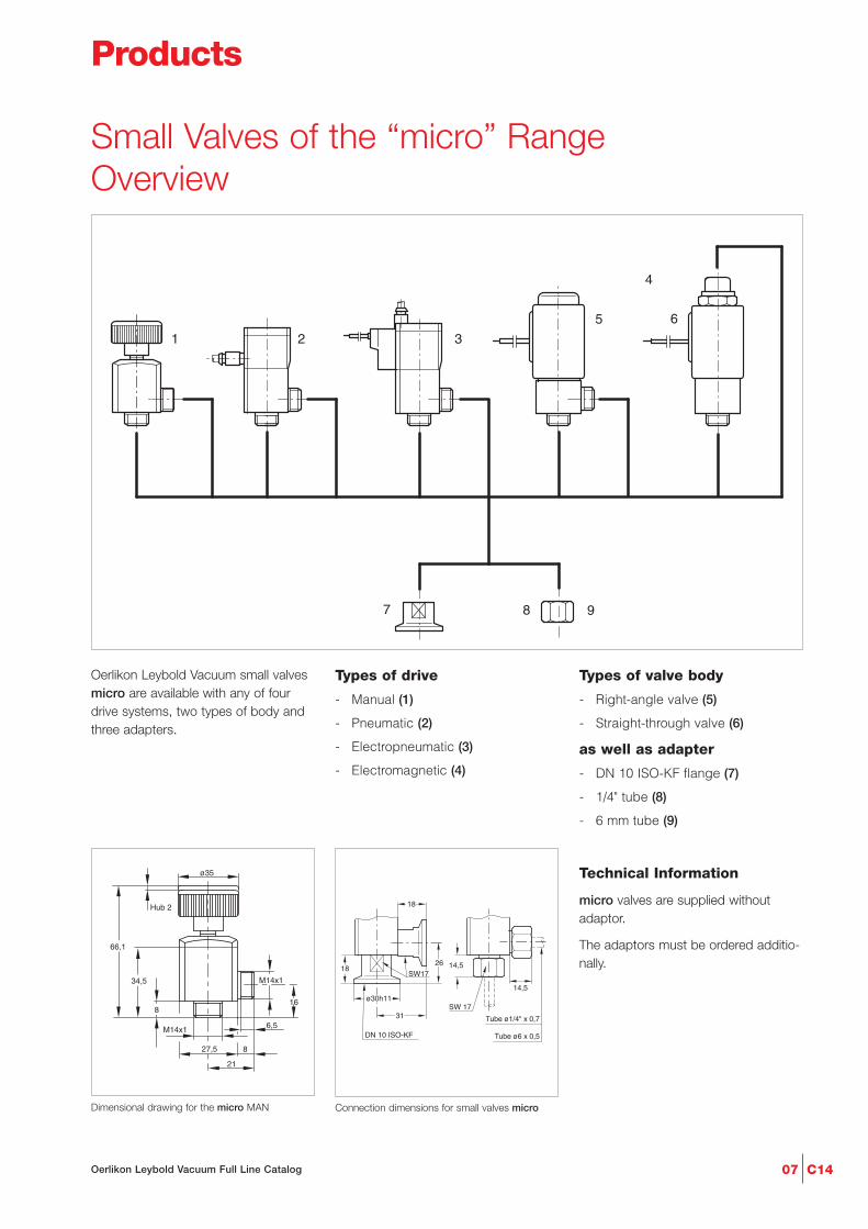
Oerlikon Leybold Vacuum small valvesmicro are available with any of fourdrive systems, two types of body andthree adapters.
Types of drive
- Manual (1)
- Pneumatic (2)
- Electropneumatic (3)
- Electromagnetic (4)
Types of valve body
- Right-angle valve (5)
- Straight-through valve (6)
as well as adapter
- DN 10 ISO-KF flange (7)
- 1/4" tube (8)
- 6 mm tube (9)
Technical Information
micro valves are supplied withoutadaptor.
The adaptors must be ordered additio-nally.
2 3
5 6
7 8 9
1
4
21
8
6,5
27,5
ø35
8
34,5
66,1
Hub 2
M14x1
M14x1
16
Dimensional drawing for the micro MAN
Tube ø6 x 0,5
Tube ø1/4" x 0,731
DN 10 ISO-KF
26 14,5
SW 17
14,5
SW17
ø30h11
18
18
Connection dimensions for small valves micro
Small Valves of the “micro” RangeOverview
Products

C14 08 Oerlikon Leybold Vacuum Full Line Catalog
6,5
6,5
30,5
29
29
8
21
59,5
ø4
20
16
M14x1
M14x1
8
Dimensional drawing for the pneumatically actua-ted small valves micro
6,5
ø4
32
29
6,5
8
21
64
10,3
16
M14x1
M14x1
29,5
5003,5
8
Dimensional drawing for the electropneumaticallyactuated small valves micro
6,5M14x1
25/
2
6,5
6,5
302
500
88
SW19
500
16
8
21
8
82
M14x1 M14x1
76
M14x1
/
8
6,5
30/
25/
Dimensional drawing for the electromagneticactuated small valves micro
Right-Angle and Straight-Through Valves,Bellows-Sealed, Various Drives
Advantages to the User
- Small size
- High conductance in the mole-cular flow range
- Long service life of over 2 millionswitching cycles
- High switching frequency
- Protection class IP 50
Typical Applications
- Gas handling systems in produc-tion machines
- Latest generation analytical equip-ment
Technical Data Small Valves “micro”
Manual Electropneumatic Pneumatic ElectromagneticNominal width mm
Integral leak rate mbar x l/s
Switching cycles
Max. pressure differential bar abs.
Closure time ms
Opening time ms
Max. switching frequency min-1
Conductance, molecular l/s
Supply voltage V DC
Max. power consumption W
MaterialValve body
Inside section
GasketsDrive
5 5 5 5
10-9 10-9 10-9 10-9
– 5 mio. 5 mio. 2 mio.
4 3 3 1
– 35 35 7
– 35 35 30
– 150 150 300
0.4 0.4 0.4 0.3
– 24 (with pilot valve) – 24
– 1 – 10
stainless steel stainless steel (1.4301) stainless steel (1.4301) stainless steel (1.4301)(1.4301)
stainless steel stainless steel (1.4301) stainless steel (1.4301) stainless steel (1.4301)(1.4301)
O-rings of FPM O-rings of FPM O-rings of FPM O-rings of FPMaluminum/ aluminum anodized aluminum anodized stainless steel 1.4105
plastic

C1409Oerlikon Leybold Vacuum Full Line Catalog
Ordering Information
Part No.
284 48 – – –
– – Part No. 284 40 –
– Part No. 284 41 – –
– Part No. 284 42 – –
– – Part No. 284 47 –
– – – Part No. 284 44
– – – Part No. 284 45
– – – Part No. 284 46
Part No.
284 50 Part No. 284 50 Part No. 284 50 Part No. 284 50
Part No.
284 51 Part No. 284 51 Part No. 284 51 Part No. 284 51
Part No.
284 52 Part No. 284 52 Part No. 284 52 Part No. 284 52
Part No.
105 80 Part No. 105 81 Part No. 105 81 Part No. 108 82
Part No.
105 85 Part No. 105 82 Part No. 105 82 Part No. 105 83/84/89
Right-Angle Valves Type
Manual MAN
Without pilot valve,
normally closed PE
With pilot valve, normally closed EPE
With pilot valve, normally open EPE
With pilot valve, normally closed,
with flanges PE DN 10 ISO-KF
Electromagnetic,
normally closed EME
Straight-Through Valves
Electromagnetic, normally closed EMD
Electromagnetic, normally open EMD
Adapter (1 piece)
Flange DN 10 ISO-KF
Tube 1/4"
Tube 6 mm
Spare parts
Seal kit
Inside section
Small Valves “micro”
Manual Electropneumatic Pneumatic Electromagnetic

C14 10 Oerlikon Leybold Vacuum Full Line Catalog
Notes

C1411Oerlikon Leybold Vacuum Full Line Catalog
Valves with ISO-KF FlangesOverview
7
3
8
6
5
4
1
+
5
5
1 1
1
Foto
2
Oerlikon Leybold Vacuum ISO-KF valves are available with any of fourdrive systems and four types of bodyhaving a nominal width of DN 16, 25,40 and 50 ISO-KF.
Types of drive
- Rotary knobwith bellows seal
- Pneumaticwith bellows seal
- Electropneumaticwith bellows seal
- Solenoid with bellows seal
Types of valve body
- Right-angle valve, aluminum body
- Right-angle valve, stainless steel body
- Straight-through valve, stainless steel body
- Straight-through valve, aluminum body
Abbreviations used in con-nection with bellows sealedvalves:
B Bellows sealed
A Angle (valve)
I Inline (valve)
V Valve
M Rotary knob
P Pneumatically actuated
EP Electropneumatically actuated
EM Electromechanically actuated
AL Aluminum body
SS Stainless steel body
BAV ... EP AL ...
1
3
2
8
5
6
7
Materials Used
Aluminum version Stainless steel versionHousing Aluminum (AlMgSi) Stainless steel (AISI 304)
EN-AW 6060 1)
Inner section 1) Aluminum (AlMgSi) Stainless steel (AISI 304)Drive unit 2) Aluminum AluminumValve disk AISI 316L AISI 316LBellows AISI 316L (1.4404) AISI 316L (1.4404)Head and disk O-ring Viton VitonRotary knob Plastic PlasticPosition indicating cover 2) Plastic PlasticHousing cover 1) Plastic Plastic1) For the solenoid version only2) For pneumatic and electro-pneumatic version only
4

C14 12 Oerlikon Leybold Vacuum Full Line Catalog
Ordering Information
Right-Angle Valve, rotary knobBAV ... M AL
BAV ... M SS
Spare partsBellows feedthrough
Knob‘
Seal kit consisting ofdisc seal (O-ring) andhead seal (O-ring)
Dimensional drawing for the manually operated,bellows-sealed, right-angle valves
Right-Angle Valves, Bellows-Sealed, Manually Operated
Advantages to the User
Valves with Rotary Knob
- Allow also for reduced venting ofsystems
- Suited as a manually operatedvariable leak valve to roughlycontrol gas flows
- Leak tight in both directions up toa pressure of 2.0 etc. 1.5 bar andeasy to open
- Installation in any orientation
Technical Data DN 16 ISO-KF DN 25 ISO-KF DN 40 ISO-KF DN 50 ISO-KF
Aluminum Stainl. Steel Aluminum Stainl. Steel Aluminum Stainl. Steel Aluminum Stainl. Steel
Service life cycles
Conductance at molecular flow l x s-1
Leak rate mbar x l x s-1
Operating pressure range mbar
Differential pressure, closing and opening direction bar
Ambient / operating temperature, max. °C
Seal
Weight kg
20,000 20,000 20,000 20,000 20,000 20,000 20,000 20,000
5 5 14 14 45 45 50 50
1 x 10⁻⁹ 1 x 10⁻⁹ 1 x 10⁻⁹ 1 x 10⁻⁹ 1 x 10⁻⁹ 1 x 10⁻⁹ 1 x10⁻⁹ 1 x 10⁻⁹
10-8 - 5000 10-8 - 5000 10-8 - 5000 10-8 - 5000 10-8 - 5000 10-8 - 5000 10-8 - 5000 10-8 - 5000
5 / 2 5 / 2 5 / 2 5 / 2 5 / 2 5 / 2 5 / 2 5 / 2
80 80 80 80 80 80 80 80
FPM FPM FPM FPM FPM FPM FPM FPM
0.24 0.30 0.36 0.47 0.92 1.08 1.34 1.52
Dimension Table
DN
A
B
D
L 1)
L1 2)
Q
V
Z 3)
1) Aluminum version2) Stainless steel version3) Disk stroke is greater due to the transmission
ISO-KF 16 25 40 50
mm 40 50 65 70
mm 40 48 65 77
mm 16 25 40 50
mm 64.9 60.9 94.3 101.1
mm 67.4 64.3 97.3 104.1
mm 46.0 44.0 73.5 85.5
mm 40 40 60 60
mm 3.6 4.7 7.9 9.3
Part No. Part No. Part No. Part No.215 375 – 215 376 – 215 377 – 215 378 –
Part No. Part No. Part No. Part No.– 215 383 – 215 385 – 215 386 – 215 387
Part No. Part No. Part No. Part No. Part No. Part No. Part No. Part No.242 292 242 292 233 014 233 014 229 542 229 542 244 980 244 980Part No. Part No. Part No. Part No. Part No. Part No. Part No. Part No.245 912 245 912 245 912 245 912 245 913 245 913 245 913 245 913
Part No. Part No. Part No. Part No. Part No. Part No. Part No. Part No.242 324 242 324 241 077 241 077 241 079 241 079 245 556 245 556
DN 16 ISO-KF DN 25 ISO-KF DN 40 ISO-KF DN 50 ISO-KF
Aluminum Stainl. Steel Aluminum Stainl. Steel Aluminum Stainl. Steel Aluminum Stainl. Steel
Connection Icons
Side of the valve seat
Required clearance
Mechanical position indicator
Leak detection bore
C1413Oerlikon Leybold Vacuum Full Line Catalog
Ordering Information
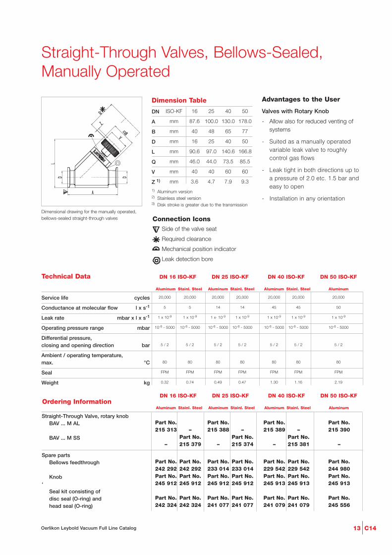
Dimensional drawing for the manually operated,bellows-sealed straight-through valves
Straight-Through Valves, Bellows-Sealed, Manually Operated
Advantages to the User
Valves with Rotary Knob
- Allow also for reduced venting ofsystems
- Suited as a manually operatedvariable leak valve to roughlycontrol gas flows
- Leak tight in both directions up toa pressure of 2.0 etc. 1.5 bar andeasy to open
- Installation in any orientation
Technical Data DN 16 ISO-KF DN 25 ISO-KF DN 40 ISO-KF DN 50 ISO-KF
Aluminum Stainl. Steel Aluminum Stainl. Steel Aluminum Stainl. Steel Aluminum
Service life cycles
Conductance at molecular flow l x s-1
Leak rate mbar x l x s-1
Operating pressure range mbar
Differential pressure, closing and opening direction bar
Ambient / operating temperature, max. °C
Seal
Weight kg
20,000 20,000 20,000 20,000 20,000 20,000 20,000
5 5 14 14 45 45 50
1 x 10⁻⁹ 1 x 10⁻⁹ 1 x· 10-9 1 x 10⁻⁹ 1 x 10⁻⁹ 1 x 10⁻⁹ 1 x 10⁻⁹
10-8 - 5000 10-8 - 5000 10-8 - 5000 10-8 - 5000 10-8 - 5000 10-8 - 5000 10-8 - 5000
5 / 2 5 / 2 5 / 2 5 / 2 5 / 2 5 / 2 5 / 2
80 80 80 80 80 80 80
FPM FPM FPM FPM FPM FPM FPM
0.32 0.74 0.49 0.47 1.30 1.16 2.19
Dimension Table
DN
A
B
D
L
Q
V
Z 1)
1) Aluminum version2) Stainless steel version3) Disk stroke is greater due to the transmission
ISO-KF 16 25 40 50
mm 87.6 100.0 130.0 178.0
mm 40 48 65 77
mm 16 25 40 50
mm 90.6 97.0 140.6 166.8
mm 46.0 44.0 73.5 85.5
mm 40 40 60 60
mm 3.6 4.7 7.9 9.3
Part No. Part No. Part No. Part No.215 313 – 215 388 – 215 389 – 215 390
Part No. Part No. Part No.– 215 379 – 215 374 – 215 381 –
Part No. Part No. Part No. Part No. Part No. Part No. Part No.242 292 242 292 233 014 233 014 229 542 229 542 244 980Part No. Part No. Part No. Part No. Part No. Part No. Part No.245 912 245 912 245 912 245 912 245 913 245 913 245 913
Part No. Part No. Part No. Part No. Part No. Part No. Part No.242 324 242 324 241 077 241 077 241 079 241 079 245 556
Straight-Through Valve, rotary knobBAV ... M AL
BAV ... M SS
Spare partsBellows feedthrough
Knob‘
Seal kit consisting ofdisc seal (O-ring) andhead seal (O-ring)
DN 16 ISO-KF DN 25 ISO-KF DN 40 ISO-KF DN 50 ISO-KF
Aluminum Stainl. Steel Aluminum Stainl. Steel Aluminum Stainl. Steel Aluminum
Connection Icons
Side of the valve seat
Required clearance
Mechanical position indicator
Leak detection bore

C14 14 Oerlikon Leybold Vacuum Full Line Catalog
Dimensional drawing right-angle valves, with fitted pilot valve
Right-Angle Valves, Bellows-Sealed,(Electro)pneumatically Operated
Advantages to the User
- Quiet opening and closing actionwith very little vibration
- Short opening and closing times
- Optical valve position indicator asstandard
- Very low leak rate and insensitiveto particles owing to bellows seal.Always closed in case the com-pressed air supply fails
- Electric position indicator isstandard
- With and without pilot valve asstandard
- Standard electrical and compres-sed air connections
- Protection class IP 50
- The valves are closed by therestoring force of a spring
- Installation in any orientation andno restrictions as to the directionof flow
Dimension Table
DN
A
B
D
L 1)
L1 2
Q
F
Z 1)
E
E1
1) Aluminum version2) Stainless steel version
ISO-KF 16 25 40 50
mm 40 50 65 70
mm 40 48 65 77
mm 16 25 40 50
mm 65.2 60.6 87.7 96.0
mm 67.7 64.0 90.7 99.0
mm 46.0 44.0 73.5 85.5
mm 9 13 19 20
mm 2.0 4.0 9.5 10.0
mm 35.6 30.6 51.6 58.4
mm 38.1 34.0 54.6 61.4
Connection Icons
Side of the valve seat
Required clearance
Mechanical position indicator
Leak detection bore
Electrical connection
Compressed air connection

C1415Oerlikon Leybold Vacuum Full Line Catalog
Ordering Information
Right-angle valves, bellows sealedBAV ... P AL
BAV ... P SS
BAV ... P AL 24 V AC
BAV ... P SS 24 V AC
BAV ... P AL 24 V DC
BAV ... P SS 24 V DC
BAV ... P AL 115 V AC
BAV ... P SS 115 V AC
BAV ... P AL 230 V AC
BAV ... P SS 230 V AC
Spare partsBellows feedthrough
Seal kit consisting ofdisc seal (O-ring) andhead seal (O-ring)
Technical DataDN 16 ISO-KF DN 25 ISO-KF DN 40 ISO-KF DN 50 ISO-KF
Aluminum Stainl. Steel Aluminum Stainl. Steel Aluminum Stainl. Steel Aluminum Stainl. Steel
Service life cycles
Conductance at molecular flow l x s-1
Leak rate mbar x l x s-1
Operating pressure range mbar
Differential pressure. closing and opening direction bar
Opening against differential pressure at the valve disk bar
Ambient / Operating temperature, max. °C
Seal
Closing time / opening time ms
Switching frequency 1/min
Electrical position indicator, load capacity V AC / A
V DC / A
Compressed air, overpressure bar
Air cylinder, volume cm3
Compressed air connection mm
Weight, with pilot valve kg
10 mio. 10 mio. 10 mio. 10 mio. 10 mio. 10 mio. 10 mio. 10 mio.
5 5 14 14 45 45 80 80
1 · 10-9 1 · 10-9 1 · 10-9 1 · 10-9 1 · 10-9 1 · 10-9 1 · 10-9 1 · 10-9
10-8 - 5000 10-8 - 5000 10-8 - 5000 10-8 - 5000 10-8 - 5000 10-8 - 5000 10-8 - 5000 10-8 - 5000
5 / 2 5 / 2 5 / 2 5 / 2 5 / 2 5 / 2 5 / 2 5 / 2
4 4 4 4 2 2 2 2
80 80 80 80 80 80 80 80
FPM FPM FPM FPM FPM FPM FPM FPM
100 / 100 100 / 100 210 / 120 210 / 120 550 / 250 550 / 250 650 / 400 650 / 400
100 100 100 100 100 100 100 100
50 / 0.1 50 / 0.1 50 / 0.1 50 / 0.1 50 / 0.1 50 / 0.1 50 / 0.1 50 / 0.1
50 / 0.1 50 / 0.1 50 / 0.1 50 / 0.1 50 / 0.1 50 / 0.1 50 / 0.1 50 / 0.1
4 to 8 4 to 8 4 to 8 4 to 8 4 to 8 4 to 8 4 to 8 4 to 8
0.004 0.004 0.011 0.011 0.035 0.035 0.047 0.047
4 and 6 4 and 6 4 and 6 4 and 6 4 and 6 4 and 6 4 and 6 4 and 6
0.24 0.30 0.36 0.47 0.92 1.08 1.34 1.52
Part No. Part No. Part No. Part No.215 315 – 215 316 – 215 317 – 215 318
Part No. Part No. Part No. Part No.– 215 335 – 215 336 – 215 337 – 215 338
Part No. Part No. Part No. Part No.215 319 – 215 320 – 215 321 – – 215 322
Part No. Part No. Part No. Part No.– 215 339 – 215 340 – 215 341 – 215 342
Part No. Part No. Part No. Part No.215 323 – 215 324 – 215 325 – 215 326 –
Part No. Part No. Part No. Part No.– 215 347 – 215 348 – 215 349 – 215 350
Part No. Part No. Part No. Part No.215 327 – 215 328 – 215 329 – – 215 330
Part No. Part No. Part No. Part No.– 215 351 – 215 352 – 215 353 – 215 354
Part No. Part No. Part No. Part No.215 331 – 215 332 – 215 333 – 215 334 –
Part No. Part No. Part No. Part No.– 215 343 – 215 344 – 215 345 – 215 346
Part No. Part No. Part No. Part No. Part No. Part No. Part No. Part No.242 292 242 292 233 014 233 014 229 542 229 542 244 980 244 980
Part No. Part No. Part No. Part No. Part No. Part No. Part No. Part No.242 324 242 324 241 077 241 077 241 079 241 079 245 556 245 556
DN 16 ISO-KF DN 25 ISO-KF DN 40 ISO-KF DN 50 ISO-KF
Aluminum Stainl. Steel Aluminum Stainl. Steel Aluminum Stainl. Steel Aluminum Stainl. Steel

C14 16 Oerlikon Leybold Vacuum Full Line Catalog
340850
Dimensional drawing for the straight-through valveswith fitted pilot valve (EP)without pilot valve (P)1) pilot valve
Straight-Through Valves, Bellows-Sealed,(Electro)pneumatically Operated
Advantages to the User
- Quiet opening and closing actionwith very little vibration
- Short opening and closing times
- Optical valve position indicator asstandard
- Very low leak rate and insensitiveto particles owing to bellows seal –thus always closed in case thecompressed air supply fails
- Electric position indicator is standard
- With and without pilot valve asstandard
- Protection class IP 50
- Standard electrical and com-pressed air connections
- The valves are closed by therestoring force of a spring
Dimension Table
DN
A
B
D
L
Q
E
Z
M
ISO-KF 16 25 40 50
mm 80 100 130 178
mm 40 48 65 77
mm 16 25 40 50
mm 91.5 100.3 140.9 170.1
mm 46.0 44.0 73.5 85.5
mm 29.6 30.0 36.1 37.6
mm 2.,0 4.0 9.5 10.0
mm 120 125 160 185
1)
Connection Icons
Side of the valve seat
Required clearance
Mechanical position indicator
Leak detection bore
Electrical connection
Compressed air connection

C1417Oerlikon Leybold Vacuum Full Line Catalog
Ordering Information
Technical DataDN 16 ISO-KF DN 25 ISO-KF DN 40 ISO-KF DN 50 ISO-KF
Aluminum Stainl. Steel Aluminum Stainl. Steel Aluminum Stainl. Steel Aluminum
DN 16 ISO-KF DN 25 ISO-KF DN 40 ISO-KF DN 50 ISO-KF
Aluminum Stainl. Steel Aluminum Stainl. Steel Aluminum Stainl. Steel Aluminum
Service life cycles
Conductance at molecular flow l x s-1
Leak rate mbar x l x s-1
Operating pressure range mbar
Differential pressure,
closing and opening direction bar
Opening against differential pressure
at the valve disk bar
Ambient / Operating temperature,
max. °C
Seal
Closing time / opening time ms
Switching frequency 1/min
Electrical position indicator,
load capacity V AC / A
V DC / A
Compressed air, overpressure bar
Air cylinder, volume cm3
Compressed air connection mm
Weight, with pilot valve kg
10 mio. 10 mio. 10 mio. 10 mio. 10 mio. 10 mio. 10 mio.
5 5 14 14 45 45 80
1x 10⁻⁹ 1 x 10⁻⁹ 1 x 10⁻⁹ 1 x 10⁻⁹ 1 x 10⁻⁹ 1 x 10⁻⁹ 1 x 10⁻⁹
10-8 - 5000 10-8 - 5000 10-8 - 5000 10-8 - 5000 10-8 - 5000 10-8 - 5000 10-8 - 5000
5 / 2 5 / 2 5 / 2 5 / 2 5 / 2 5 / 2 5 / 2
4 4 4 4 2 2 2
80 80 80 80 80 80 80
FPM FPM FPM FPM FPM FPM FPM
100 / 100 100 / 100 210 / 120 210 / 120 550 / 250 550 / 250 650 / 400
100 100 100 100 100 100 100
50 / 0.1 50 / 0.1 50 / 0.1 50 / 0.1 50 / 0.1 50 / 0.1 50 / 0.1
50 / 0.1 50 / 0.1 50 / 0.1 50 / 0.1 50 / 0.1 50 / 0.1 50 / 0.1
4 to 8 4 to 8 4 to 8 4 to 8 4 to 8 4 to 8 4 to 8
0.004 0.004 0.011 0.011 0.035 0.035 0.047
4 and 6 4 and 6 4 and 6 4 and 6 4 and 6 4 and 6 4 and 6
0.32 0.74 0.49 0.47 1.30 1.16 2.19
Part No. Part No. Part No.– 215 355 – 215 356 – 215 357 –
Part No. Part No. Part No.– 215 359 – 215 360 – 215 361 –
Part No. Part No. Part No. Part No.215 314 – 215 391 – 215 392 – 215 393
Part No. Part No. Part No.– 215 367 – 215 368 – 215 369 –
Part No. Part No. Part No.– 215 371 – 215 372 – 215 373 –
Part No. Part No. Part No. .– 215 363 – 215 364 – 215 365 –
Part No. Part No. Part No. Part No. Part No. Part No. Part No.242 292 242 292 233 014 233 014 229 542 229 542 244 980
Part No. Part No. Part No. Part No. Part No. Part No. Part No.242 324 242 324 241 077 241 077 241 079 241 079 245 556
Straight-through valve, bellows sealedBIV ... P SS
BIV ... EP SS 24 V AC
BIV ... EP AL 24 V DC
BIV ... EP SS 24 V DC
BIV ... EP SS 115 V AC
BIV ... EP SS 230 V AC
Spare partsBellows feedthrough
Seal kit consisting ofdisc seal (O-ring) andhead seal (O-ring)

C14 18 Oerlikon Leybold Vacuum Full Line Catalog
Dimensional drawing for the bellows-sealed right-angle valves
Right-Angle Valves, Bellows-Sealed,Electromagnetically Operated
Advantages to the User
- Selectable operating mode:- Remote control via programma-
ble control or personal computer
- direct operation by switching the supply voltage on and off
- Well visible, unambiguous opticalposition indicator: open (greenLED) and closed (red LED)
- Integrated electrically floatingposition indicator (opto-coupler for24 V DC)
- Optical overload indicator (redflashing LED)
- Protection class IP 54
- Spring action closure, thus closedwhen the power fails
- Low operating temperature
- Inverting operation of the remotecontrol logic
- Installation in any orientation andno restrictions as to the directionof flow
Dimension Table
DN
A
B
C
D
E
F
G
ISO-KF 16 25 40
mm 170.9 193.0 246.0
mm 51.4 64.9 92.9
mm 40 50 65
mm 96.0 112.7 139.0
mm 86.0 97.3 119.5
mm 59 70 90
mm 10.0 15.4 19.5
Electromagnetic valves are particularlywell suited for vacuum systems inwhich the valves need to be remotelycontrolled and where compressed airis not readily available.
Connection IconsProtection cap
Side of the valve seat
Required clearance
Position sensor connection
Flow direction
Leak detection bore
Position indicator

C1419Oerlikon Leybold Vacuum Full Line Catalog
Ordering Information
Technical Data DN 16 ISO-KF DN 25 ISO-KF DN 40 ISO-KF
Service life cycles
Conductance at molecular flow l x s-1
Leak rate mbar x l x s-1
Operating pressure range mbar
Differential pressure,
closing and opening direction bar
Ambient / operating temperature,
max. °C
Opening / closing time ms
Switching frequency 1/min
at ambient temperature °C
Switch-off delay ms
Rating for the
valve position indicator V DC / mA
Power consumption, max. W
Actuation and holding current A
Supply voltage, max. V AC
Frequency Hz
Protection class
Weight
Aluminum body kg
Stainless steel body kg
2 mio. 2 mio. 2 mio.
4 16 40
1 x 10⁻⁹ 1 x 10⁻⁹ 1 x 10⁻⁹
10-8 - 1300 10-8 - 1300 10-8 - 1300
1.3 1.3 1.3
50 50 50
100 / 240 120 / 240 230 / 700
30, 20 30, 20 30, 20
40, 50 40, 50 40, 50
50 170 500
15 - 30 / 100 15 - 30 / 100 15 - 30 / 100
400 400 400
5.2 / 0.7 5.3 / 0.7 4.8 / 0.7
90 - 264 90 - 264 90 - 264
50/60 50/60 50/60
54 54 54
1.3 2.2 4.0
1.5 2.9 5.4
Part No. 215 004 Part No. 215 064 Part No. 215 124
Part No. 215 006 Part No. 215 079 Part No. 215 134
Part No. EK 299 001 Part No. EK 299 006 Part No. EK 299 011
Part No. EK 299 002 Part No. EK 299 007 Part No. EK 299 012
Right-angle valve, bellows-sealed,
electromagnetic actuator,
microprocessor controlled
BAV ... EM AL 240 V AC
BAV ... EM SS 240 V AC
Spare parts
Seal kit
Bellows feedthrough
DN 16 ISO-KF DN 25 ISO-KF DN 40 ISO-KF

C14 20 Oerlikon Leybold Vacuum Full Line Catalog
Oerlikon Leybold Vacuum valves withISO-K flanges are available with any oftwo drives and either of two bodies.
Types of drive
- Handwheel (1)
- Electropneumatic drive, bellows-sealed (2)
Body types
- Right-angle valve with aluminumbody (3)
- Right-angle valve with stainlesssteel body (4)
From DN 63 ISO-K only right-anglevalves are available.
Nominal widths DN 63 ISO-K and DN 100 ISO-K are available in alumi-num and stainless steel, DN 160 ISO-K in aluminum only.
Advantages to the User
- Full exchangeability of the subassemblies
- Three types of drive
- Two body options
- Standard nominal widths to DIN 28 404 and ISO 1609
- Simplified stocking of spare parts
3 4
1 2
Valves with ISO-K FlangesOverview
Connection Pictograms
Position indicator connection
Compressed air connection
Power connection
Position indicator

Ordering Information
C1421Oerlikon Leybold Vacuum Full Line Catalog
Dimensional drawing for the right-angle valves,bellows-sealed, manually operated
Right-Angle Valves, Bellows-Sealed, Manually Operated
Advantages to the User
- Gentle venting of systems
- Seal in both directions up to apressure difference of 1.5 bar
- Easy manual operation, for aneffortless vacuum-tight seal
- May also be used as a variableleak valve to roughly control gasflows
- Installation in any orientation andno restrictions as to the directionof flow
Dimension TableDN
A
B
C
D
E
ISO-K 63 100
mm 266 320
mm 124 164
mm 150 190
mm 88 108
mm 20 25
These universal valves are ideal especi-ally for smaller systems, where remotecontrol is not essential. They may bealso installed in larger systems, wherebacking pumps or condensate separa-tors or similar units are to be cut off atlonger intervals for maintenance purpo-ses by maintenance personnel.
Technical Data DN 63 ISO-K DN 100 ISO-K
Service life cycles
Conductance at molecular flow l x s-1
Leak rate mbar x l x s-1
Operating pressure range mbar
Differential pressure, closing and opening direction bar
Opening against differential pressure at the valve disk bar
Ambient / Operating temperature, max. °C
Seal
WeightAluminum body kgStainless steel body kg
MaterialValve body
Inside sectionLidGaskets
> 1.5 mio. > 1.5 mio.
140 330
1 x 10⁻⁹ 1 x 10⁻⁹
10-8 - 1500 10-8 - 1500
1.5 1.5
1.5 1.5
60 60
FPM FPM
3.6 6.16.5 11.1
aluminum alloy (3.2373.63) aluminum alloy (3.2373.63)or stainless steel (1.4305) or stainless steel (1.4305)
stainless steel (1.4541/1.4301) stainless steel (1.4541/1.4301)grey cast iron (GG 20) grey cast iron (GG 20)O-rings made of FPM O-rings made of FPM
Part No. 107 80 Part No. 107 81Part No. 107 83 Part No. 107 84
Part No. 215 251 Part No. 215 271Part No. 215 254 Part No. 215 274
Right-angle valve, bellows-sealed, manually operated
Aluminum bodyStainless steel body
Spare partsSeal kitInside section
DN 63 ISO-K DN 100 ISO-K

C14 22 Oerlikon Leybold Vacuum Full Line Catalog
Dimensional drawing for the electropneumaticallyactuated right-angle valves
Right-Angle Valves, Bellows-Sealed,Electropneumatically Operated
Advantages to the User
- Pneumatic or electropneumaticopening
- Short opening and closing times
- Optical position indicator
- Electric position indicator
- With and without pilot valve IP 54
- Protection class IP 54
- The valves are closed by therestoring force of a spring
- Installation in any orientation andno restrictions as to the directionof flow
Dimension TableDN
A
B
C
D
E
ISO-K 63 100 160
mm 250 282 366
mm 130 170 221
mm 168 208 264
mm 88 108 138
mm 14 14 14
mm 6 6 6
Electropneumatically actuated right-angle valves are used in automatedvacuum systems which need to becontrolled electrically.

Ordering Information
C1423Oerlikon Leybold Vacuum Full Line Catalog
Technical Data DN 63 ISO-K DN 100 ISO-K DN 160 ISO-K
Service life, cycles Million
Conductance for molecular flow l x s-1
Leak rate mbar x l x s-1
Operating pressure range mbar
Differential pressure, closing and opening direction bar
Opening against differential pressure at the valve disk bar
Ambient / operating temperature, max. °C
Seal
Closing time / opening time ms
Switching frequency 1/min
Position indicator, rating V AC / AV DC / A
Compressed air, overpressure bar
Compressed air volume cm3
Compressed air connection mm
Weight with pilot valveAluminum housing kgStainless steel housing kg
1.5 1.5 1.5
140 330 800
1 x 10⁻⁹ 1 x 10⁻⁹ 1 x 10⁻⁹
1 x 10⁻⁸ - 1500 1 x 10⁻⁸ - 1500 1 x 10⁻⁸ - 1500
1.5 1.5 1.5
1.5 1.5 1.5
60 60 60
FPM FPM FPM
250 / 300 300 / 450 550 / 450
60 60 40
250 / 0.125 250 / 0.125 250 / 0.12550 / 0.25 50 / 0.25 50 / 0.25
4 to 8 4 to 8 4 to 8
75 195 570
6 6 6
4.0 6.7 11.46.8 11.7 –
Part No. 107 90 Part No. 107 91 Part No. 107 92Part No. 107 93 Part No. 107 94 –
Part No. 108 00 Part No. 108 01 Part No. 108 02Part No. 108 10 Part No. 108 11 –
Part No. 108 03 Part No. 108 04 Part No. 108 05Part No. 108 13 Part No. 108 14 –
Part No. 108 20 Part No. 108 21 Part No. 108 22– – –
Part No. 108 25 Part No. 108 26 Part No. 108 27Part No. 108 35 Part No. 108 36 –
Part No. 215 301 Part No. 215 301 Part No. 215 311Part No. 215 300 Part No. 215 300 Part No. 215 310Part No. 215 302 Part No. 215 302 Part No. 215 312
Part No. 215 251 Part No. 215 271 Part No. 215 291Part No. 215 253 Part No. 215 273 Part No. 215 293
Right-angle valve, bellows-sealed, electropneumatic drive
without solenoid coilAluminum bodyStainless steel body
Valve with pilot valve 24 V DCAluminum bodyStainless steel body
Valve with pilot valve 24 V ACAluminum bodyStainless steel body
Valve with pilot valve 100 - 115 V ACAluminum bodyStainless steel body
Valve with pilot valve 200 - 240 V ACAluminum bodyStainless steel body
Pilot valve24 V DC24 V AC200 - 240 V AC
Spare partsSeal kitInside section
DN 63 ISO-K DN 100 ISO-K DN 160 ISO-K

C14 24 Oerlikon Leybold Vacuum Full Line Catalog
DN
DN1
h
c
b
ed
h1
f
a a3
DN
1a
DN1
DN3
DN2
a2
a4
Antrieb um90° versetztgezeichnet
Dimensional drawing for the right-angle valveswith bellows
Right-Angle Valves, Bellows-Sealed,Electropneumatically Operated
Advantages to the User
- No vibrations when the valve openor closes
- Low leak rate (< 10-9 mbar x l x s-1) – drive system basicallyinsensitive to particles
- Non-contact valve position indica-tor for reliable indication of the valve’s position (open/closed)
- Wide range of different solenoidcoils for all commonly used controlvoltages
- Additional flange for bypass linesand for connecting vacuum gauges (see Product Section C16“Total Pressure Gauges”)
Dimension Table
DN
h, ca.
a
a1
a2, a4
a3
h1
DN1, for bypass 1
DN2, for bypass 2
DN3, for meas. conn.
b
c
d
e
f
Travel
Travel/DN 1)
1) For example travel = 1/4 DN
DN 250 ISO-K
mm 261
mm 650
mm 250
mm 200
mm 208
mm 205
mm 163
50 ISO-KF
40 ISO-KF
16 ISO-KF
mm 69.5
mm 218
mm 250
mm 58
mm 363
mm 62.5
mm 1/4
Right-angle valves of this size are used,for example in metallurgy, large coaters,in the area of space simulation.Drive drawn
offset by 90°

Ordering Information
C1425Oerlikon Leybold Vacuum Full Line Catalog
Technical Data DN 250 ISO-K
Service life, vertical cycles, approx.
Conductance at molecular flow l x s-1
Leak rate mbar x l x s-1
Opening / closing time,
at 6 bar compr. air pressure s
Compressed air, overpressure bar
Hose diameter mm
Compressed air cylinder, volume cm3
Max. ambient temperature °C
Weight kg
Supply voltage V
Material
Body, valve disk
Drive / Compressed air cylinder
Piston rod, Intermediate flange
Gaskets
Lid
Hood
1 x 10⁶
2700
1 x 10⁻⁹
6 / 6
4 to 8
6 x 1
2100
40
66
Various voltages are possible;
see section “Special Valves with ISO-KF / ISO-K / CF Flanges”,
para. “Accessories for the Electropneumatically Operated Valves”,
product “Solenoid Coils”
stainless steel
aluminum / cast aluminum (3.2153)
stainless steel (1.4305)
FPM
aluminum (3.2341)
plastic (PA 6)
Part No. 281 84
X
Y
Part No. 105 65
Part No. 105 75
Right-angle valve, bellows-sealed,
electropneumatic drive
without solenoid coil
Stainless steel body
Solenoid coil for various supply voltages
Interference suppression kits
for different voltages
Spare parts
Seal kit
Inside section
X = Part Nos. see section “Special Valves with ISO-KF / ISO-K / CF Flanges”,para. “Accessories for the Electropneumatically Operated Valves”, product “Solenoid Coil”Y = Part Nos. see section “Special Valves with ISO-KF / ISO-K / CF Flanges”, para. “Accessories for the Electropneumatically Operated Valves”, product “Pilot Valves”
DN 250 ISO-K

71
5
6
4
C14
Special Valves with ISO-KF/ISO-K/CF Flange
26 Oerlikon Leybold Vacuum Full Line Catalog
- Sealing Valves
- Variable leak valves
- Ball Valves
- Right-angle valves for mobilesystems in accordance with theAmerican standard of the Depart-ment of Transportation (DOT)
These valves ideally supplement ourrange of ISO-KF and ISO-K valves.
Overview
6
2
75
4
3
1
Oerlikon Leybold Vacuum offers arange of special valves for a variety ofdifferent applications and to meet spe-cial design requirements of customers.
Among these are:- SECUVAC vacuum safety valves
(DN 16 ISO-KF to DN 100 ISO-K)
- Venting Valves
- Power failure venting valves
- Vacuum Locks
2
3
4

C1427Oerlikon Leybold Vacuum Full Line Catalog
h2
h1
a
høD
a
b
Dimensional drawing for the SECUVAC valves withISO-KF small flanges
SECUVAC Vacuum Safety Valves
These solenoid right-angle valves werespecially developed for use with rotaryvacuum pumps which are not equip-ped with a built-in anti-suckback valve.The SECUVAC safety valve protectsthe vacuum system against unplannedventing via the backing pump in caseof a power failure and it ensures thatthe vacuum system remains sealeduntil the backing pump, after it hasrestarted, has evacuated the connect-ing lines.
Dimension Table (ISO-KF)
a
b
D
h
h1
h2
DN 16 ISO-KF 25 ISO-KF 40 ISO-KF
mm 40 50 65
mm 49 49 49
mm 44 56 82
mm 138.6 161.8 178.3
mm 62.3 82.5 100.0
mm 24 27 26
h
D
h2
a
a
h1
b
Dimensional drawing for the SECUVAC valves withISO-K clamp flanges
Dimension Table (ISO-K)
a
b
D
h
h1
h2
DN 63 ISO-K 100 ISO-K
mm 88 108
mm 49 49
mm 124 164
mm 220.5 263.5
mm 150 175
mm 18.2 36.2
Advantages to the User
Two valve functions in one:
- Fast-closing high vacuum isolationvalve for separating the vacuumchamber or a vapor jet pump (adiffusion pump, for example) fromthe backing pump
- Venting valve for venting of thevalve’s chamber and thus thepump (backing pump)
- Immediate closing action uponpower failure
- Opening action only after the in-take line has been evacuated
- Delayed isolation of the vacuumchamber and venting the vacuumpump (negligible “gulp”)
Typical Applications
- Safety isolation valve betweenbacking pump and vacuum cham-ber or vapor jet pumps (protectionof the vacuum chamber againstventing in the event of a power fai-lure)
C14 28 Oerlikon Leybold Vacuum Full Line Catalog
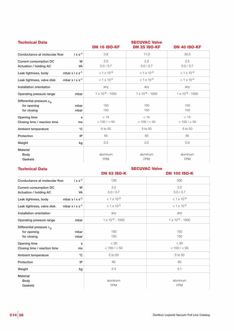
Technical Data SECUVAC ValveDN 16 ISO-KF DN 25 ISO-KF DN 40 ISO-KF
Conductance at molecular flow l x s-1
Current consumption DC W
Actuation / holding AC VA
Leak tightness, body mbar x l x s-1
Leak tightness, valve disk mbar x l x s-1
Installation orientation
Operating pressure range mbar
Differential pressure Dpfor opening mbar
for closing mbar
Opening time s
Closing time / reaction time ms
Ambient temperature °C
Protection IP
Weight kg
Material
Body
Gaskets
3.8 11.0 30.5
2.5 2.5 2.5
5.0 / 3.7 5.0 / 3.7 5.0 / 3.7
< 1 x 10⁻⁹ < 1 x 10⁻⁹ < 1 x 10⁻⁹
< 1 x 10⁻⁵ < 1 x 10⁻⁵ < 1 x 10⁻⁵
any any any
1 x 10⁻⁸ - 1000 1 x 10⁻⁸ - 1000 1 x 10⁻⁸ - 1000
150 150 150
150 150 150
< 15 < 15 < 15
< 100 / < 50 < 100 / < 50 < 100 / < 50
5 to 50 5 to 50 5 to 50
65 65 65
0.3 0.5 0.9
aluminum aluminum aluminum
FPM FPM FPM
Technical Data SECUVAC ValveDN 63 ISO-K DN 100 ISO-K
Conductance at molecular flow l x s-1
Current consumption DC W
Actuation / holding AC VA
Leak tightness, body mbar x l x s-1
Leak tightness, valve disk mbar x l x s-1
Installation orientation
Operating pressure range mbar
Differential pressure Dpfor opening mbar
for closing mbar
Opening time s
Closing time / reaction time ms
Ambient temperature °C
Protection IP
Weight kg
Material
Body
Gaskets
126 300
2.5 2.5
5.0 / 3.7 5.0 / 3.7
< 1 x 10⁻⁹ < 1 x 10⁻⁹
< 1 x 10⁻⁵ < 1 x 10⁻⁵
any any
1 x 10⁻⁸ - 1000 1 x 10⁻⁸ - 1000
150 150
150 150
< 30 < 30
< 100 / < 50 < 100 / < 50
5 to 50 5 to 50
65 65
2.4 5.1
aluminum aluminum
FPM FPM

C1429Oerlikon Leybold Vacuum Full Line Catalog
Ordering Information
Part No. 215 205 Part No. 215 225
Part No. 215 206 Part No. 215 226
Part No. 215 207 Part No. 215 227
Part No. 105 07 Part No. 105 08
Part No. 215 242 Part No. 215 242
Part No. 215 241 Part No. 215 241
Part No. 215 240 Part No. 215 240
Part No. 215 701 Part No. 215 701
SECUVAC valve
024 V DC
100 - 115 V AC
200 - 230 V AC
Spare parts
Seal kit
Solenoid coils for SECUVAC valves
and power failure venting valves
024 V DC
100 - 115 V AC / 50/60 Hz
200 - 230 V AC / 50/60 Hz
Filter for SECUVAC valves and
power failure venting valves
(set of 5 pcs.)
SECUVAC ValveDN 63 ISO-K DN 100 ISO-K
Ordering Information
Part No. 215 015 Part No. 215 065 Part No. 215 135
Part No. 215 016 Part No. 215 066 Part No. 215 136
Part No. 215 017 Part No. 215 067 Part No. 215 137
Part No. 105 02 Part No. 105 04 Part No. 105 05
Part No. 215 242 Part No. 215 242 Part No. 215 242
Part No. 215 241 Part No. 215 241 Part No. 215 241
Part No. 215 240 Part No. 215 240 Part No. 215 240
Part No. 215 701 Part No. 215 701 Part No. 215 701
SECUVAC valve
024 V DC
100 - 115 V AC
200 - 230 V AC
Spare parts
Seal kit
Solenoid coils for SECUVAC valves
and power failure venting valves
024 V DC
100 - 115 V AC / 50/60 Hz
200 - 230 V AC / 50/60 Hz
Filter for SECUVAC valves and
power failure venting valves
(set of 5 pcs.)
SECUVAC ValveDN 16 ISO-KF DN 25 ISO-KF DN 40 ISO-KF
Interference Suppression Kit - Illuminated
As an option for the solenoid coil, aninterference suppression kit is offeredwhich reliably prevents any interferen-ces from affecting other equipmentoperating in the vicinity.
Ordering Information
Part No. 104 96
Part No. 104 95
Interference suppression kit
024 V DC
110 - 230 V AC
Interference Suppression Kit

C14 30 Oerlikon Leybold Vacuum Full Line Catalog
Safety Valve
Typical Applications
- Protecting sealed vacuum systemslike cryopumps, cryostats, lifting de-vices, for example against internaloverpressures
- Mandatory for systems which areseparated when cold, as a meansof protection against overpressures
Ordering Information
Safety valve on DN 16 ISO-KF flange
Safety Valve
Technical Data
Responding pressure mbar
Flow at 140 mbar l x h-1
Valve disk
Leak rate in the closed state
mbar x l x s-1 (Torr x l x s-1)
Connection DN
Diameter mm
Overall height mm
Weight kg
Safety Valve
120 to 160, over-pressure
500
Spring loaded, with O-ring seal
< 1 x 10⁻⁸ (< 0.75 x 10⁻⁸)
16 ISO-KF
32
28
0.3
Part No. 890 39
32
28
DN 16 ISO-KF
Dimensional drawing for the safety valve
C1431Oerlikon Leybold Vacuum Full Line Catalog
Ordering Information
DN 10 ISO-KF
30 27
65,8
64
41
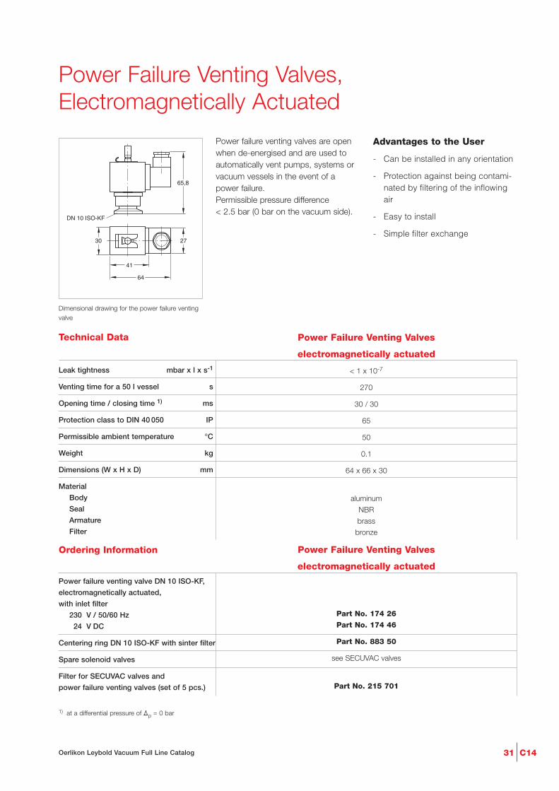
Dimensional drawing for the power failure ventingvalve
Power Failure Venting Valves,Electromagnetically Actuated
Power failure venting valves are openwhen de-energised and are used toautomatically vent pumps, systems orvacuum vessels in the event of apower failure. Permissible pressure difference < 2.5 bar (0 bar on the vacuum side).
Advantages to the User
- Can be installed in any orientation
- Protection against being contami-nated by filtering of the inflowingair
- Easy to install
- Simple filter exchange
Technical Data Power Failure Venting Valves
electromagnetically actuated
Leak tightness mbar x l x s-1
Venting time for a 50 l vessel s
Opening time / closing time 1) ms
Protection class to DIN 40 050 IP
Permissible ambient temperature °C
Weight kg
Dimensions (W x H x D) mm
Material
Body
Seal
Armature
Filter
< 1 x 10⁻⁷
270
30 / 30
65
50
0.1
64 x 66 x 30
aluminum
NBR
brass
bronze
Part No. 174 26
Part No. 174 46
Part No. 883 50
see SECUVAC valves
Part No. 215 701
Power failure venting valve DN 10 ISO-KF,
electromagnetically actuated,
with inlet filter
230 V / 50/60 Hz
024 V DC
Centering ring DN 10 ISO-KF with sinter filter
Spare solenoid valves
Filter for SECUVAC valves and
power failure venting valves (set of 5 pcs.)
1) at a differential pressure of Vp = 0 bar
Power Failure Venting Valves
electromagnetically actuated

Ordering Information
C14 32 Oerlikon Leybold Vacuum Full Line Catalog
Dimensional drawing for the coarse variable leakvalve without isolation valve
Coarse Variable Leak Valvewithout Isolation Valve
With coarse variable leak valves with-out isolation valve precisely definedquantities of gas may be admitted within a controllable period of time intoevacuated vessels.
Applications
- Gas admission rates of 40 to 1700 mbar x l x s-1 allow coarsevariable leak valves to be used inalmost all applications
Technical Data Coarse Variable Leak Valve
without Isolation Valve
Gas flow controllable mbar x l x s-1
Tightness mbar x l x s-1
Differential pressure bar
Operating temperature °C
Material (housing / valve disk)
Seal
Weight kg
40 - 1700
1 x 10⁻⁹
3
100
aluminum / stainless steel
FPM
0.2
Part No. 215 020Coarse variable leak valve
without isolation valve, DN 10 ISO-KF
Coarse Variable Leak Valve
without Isolation Valve
00
1
2
3
4
Gas flow
200 400 600 800 1000 1200 1400 1800mbar x l/s
Spi
ndle
rot
atio
n
Variable leak characteristic for the coarse variable leak valve without isolation valve
= Preferred flow direction

C1433Oerlikon Leybold Vacuum Full Line Catalog
Ordering Information
DN 16 ISO-KF
DN 16 ISO-KF
Ansicht A
A
ø42 (1,65")
30 (1,18")
117,5(4,63")
130(5,12")
30(1,18")
Close
2 4 3
Dimensional drawing for the variable leak valve with isolation valve
Variable Leak Valve with Isolation Valve
Variable leak valves with a isolationvalve permit an interruption of the gassupply without changing the gas ad-mission rate setting.
Applications
- Gas admission rates of 1000 to 5 x 10⁻⁶ mbar x l x s-1 allow varia-ble leak valves to be used in al-most all applications
- Through the integrated digital dis-play, the opening point may beaccurately set at any time or a certain gas flow may be defined
- Blocking valve
Technical Note
When using helium as the processgas, it must be taken into account thatthe needle sleeve made of modifiedPTFE is to a certain extent permeableto helium.
Technical Data Variable Leak Valve
with Isolation Valve
Gas flow controllable mbar x l x s-1
Tightness mbar x l x s-1
Differential pressure bar
Dead volume cm3
Operating temperature °C
Bakeout temperature, flanges °C
Material (housing, needle, filter)
Material (needle sleeve)
Seal
Weight kg
5 x 10⁻⁶ - 1000
1 x 10⁻⁹
2.5
0.032
80
150
stainless steel
fluorplastomer
FPM
0.4
Part No. 215 010Variable leak valve with isolation valve, DN 16 ISO-KF
Variable Leak Valve
with Isolation Valve
1
10-6 10-5 10-4 10-3 10-2
Gas flow
10-1 100 101
mbar x I/s103
10
100
1000
Ska
le d
ivis
ions
Variable leak characteristic for the variable leak valve with isolation valve
Close
2 4 3Quick shut off ring
View A
Dimension in ( ) = Dimension in inch= Preferred flow direction

C14 34 Oerlikon Leybold Vacuum Full Line Catalog
Ordering Information
Dimensional drawing for the venting valve,manually operated
Venting Valves, Manually Operated
Venting valves are used to vent smallvacuum systems.
Advantages to the User
- Simple opening and closing of thevalve by loosening or tighteningthe screw cap
Technical Data Venting Valve
manually operated
Tightness mbar x l x s-1
Weight kg
Dimensions (W x H x D) mm
Material
Body
Inside section
Seal
Screw cap
< 1 x 10⁻⁹
0.15
51 x 42 x 30
aluminum (3.0615), stainless steel (1.4301)
aluminum (3.0615), stainless steel (1.4301)
FPM
brass (nickel-plated)
Part No. 173 24
Part No. 173 37
Venting valve DN 10 ISO-KF,
manually operated (screw cap)
Aluminum
Stainless steel
Venting Valve
manually operated

Ordering Information
C1435Oerlikon Leybold Vacuum Full Line Catalog
Dimensional drawing for the venting valve,electromagnetically actuated
Venting Valves, Electromagnetically Actuated
Venting valves are used to vent smallvacuum systems and are closed whenno power is applied.
Advantages to the User
- Open when power is applied, closed with no power
- Seals on one side against atmos-pheric pressure
- Protected against dirt by a filter
Technical Data Venting Valve
electromagnetically actuated
Leak rate mbar x l x s-1
Venting time for a 100 l chamber s
Mains connection V / HzV / HzV DC
Power consumption, actuation / holding VA
Differential pressure in closing / opening direction bar
Can be openedto a pressure difference of bar
Service life cycles
Switching frequency 1/min
Opening / closing time ms
Conductance for molecular flow l x s-1
Weight kg
Dimensions (W x H x D) mm
MaterialValve bodyGasket
< 1 x 10⁻⁹
23
230 / 50/60115 / 50/60
24
35 / 15
10 / 1
2
1.5 Mio.
50
60 / 45
1
0.46
105 x 120 x 42
aluminumFPM
Part No. 215 021Part No. 215 023Part No. 215 024
Part No. 215 011Part No. 215 014
Part No. 883 50
Part No. 215 208
Venting valve DN 10 ISO-KF, electromagnetically actuated
024 V DC115 V AC230 V AC
Spare coilfor 024 V DCfor 230 V AC
Centering ring with sintered metal filter, DN 10 ISO-KF
Seal kit
Venting Valve
electromagnetically actuated

C14 36 Oerlikon Leybold Vacuum Full Line Catalog
DN
a
h
a
h2
d
Dimensional drawing for the sealing valves
Vacuum Locks and Sealing Valves
A screw-in sealing element with a hex.socket into which the spindle of thegas lock is inserted for actuation hasbeen integrated within the tubulation.
After having filled in the gas or evacua-ted the chamber, the gas lock is deta-ched from the small flange and maythus be reused for an unlimited num-ber of times on other sealing valves.
Advantages to the User
- Simple to use, handy knob
- Compact, low weight
- Also well-suited for operating oldertypes of sealing valves from Oerlikon Leybold Vacuum
- Long travel and high conduc-tance, thus short pumpdown times
- Spindle can be arrested in its endposition
- Double O-ring seal offering a verylow leak rate (< 1 x 10⁻⁷ mbar x l x s-1) and a long service life
Dimension Table
a
d
h
h2
DN 16 ISO-KF 25 ISO-KF 40 ISO-KF
mm 40 50 65
mm 16 25 38
mm 124 160 190
mm 30 30 40
- May be used in the entire roughand medium vacuum range
- Long service life
- Secured against inadvertent open-ing
- Temperature resistantVacuum lock 60 °CBlocking valve 100 °C
- May be protected by a standardblank flange against becomingdirty
Typical Applications
- Sealing of evacuated or gas-filledchambers
- Post-evacuation of vessels
- Topping up and exchanging thegas filling in vessels
- Sealing valves with stainless steelISO-KF connection and stainlesssteel tubulation for welding to thechamber

Ordering Information
C1437Oerlikon Leybold Vacuum Full Line Catalog
Technical Data Vacuum Lock / Sealing Valve
DN 16 ISO-KF DN 25 ISO-KF DN 40 ISO-KF
Leak rate
Sealing valve mbar x l x s-1
Vacuum lock mbar x l x s-1
Travel for the vacuum lock mm
Free passage in the sealing valve mm
Absolute pressure bar
Weight
Vacuum lock kg
Sealing valve kg
Material
Vacuum lock
Seal
1 x 10⁻⁷ 1 x 10⁻⁷ 1 x 10⁻⁷
1 x 10⁻⁹ 1 x 10⁻⁹ 1 x 10⁻⁹
56 76 108
3 8 18
2.5 2.5 2.5
0.5 1.0 1.8
0.04 0.1 0.12
aluminum aluminum aluminum
FPM FPM FPM
Part No. 283 25 Part No. 283 26 Part No. 283 27
Part No. 283 21 Part No. 283 22 Part No. 283 23
Part No. 183 41 Part No. 183 42 Part No. 183 43
Part No. 883 46 Part No. 883 47 Part No. 883 48
Part No. 215 055 Part No. 215 056 Part No. 215 057
Part No. 107 70 Part No. 107 71 Part No. 107 72
Vacuum lock, aluminum body
Sealing valve with tubulation,
stainless steel body
Clamping ring
Centering ring
Repair kit
Vacuum lock
Sealing valve
Vacuum Lock / Sealing Valve
DN 16 ISO-KF DN 25 ISO-KF DN 40 ISO-KF

C14 38 Oerlikon Leybold Vacuum Full Line Catalog
Ordering Information
DN
h1
h2
DN
b
b1
D
h
Dimensional drawing for the ball valves
Ball Valves
Ball valves are rugged and cost-effec-tive straight-through valves of smallsize, which are opened or closed sim-ply by operating a lever. The valveposition (OPEN/CLOSED) can bedetermined from the lever’s position.The lever may be detached.
Ball valves are provided with lubricatedgaskets and when open they permit anunobstructed passage.
Advantages to the User
- Leak tight on both sides againstthe atmosphere; can be openedagainst atmospheric pressure
Technical Data Ball Valve
DN 10 ISO-KF DN 16 ISO-KF DN 25 ISO-KF DN 40 ISO-KF
Leak rate mbar x l x s-1
Conductance for molecular flow l x s-1
Pressure absolute,
min. / max. mbar / bar
Weight kg
Material
Body
Gaskets
Ball
ISO-KF flanges
< 1 x 10⁻⁶ < 1 x 10⁻⁶ < 1 x 10⁻⁶ < 1 x 10⁻⁶
1.5 3 9 30
10-5 / 5 10-5 / 5 10-5 / 5 10-5 / 5
0.35 0.4 0.75 2.6
brass (nickel-plated) brass (nickel-plated) brass (nickel-plated) brass (nickel-plated)
PTFE PTFE PTFE PTFE
brass (hard brass (hard brass (hard brass (hard
chromium-plated) (chromium-plated) chromium-plated) chromium-plated)
aluminum (3.0615) aluminum (3.0615) aluminum (3.0615) aluminum (3.0615)
Part No. 174 94 Part No. 174 95 Part No. 174 96 Part No. 174 97Ball valve
Brass body (nickel-plated)
Ball Valve
DN 10 ISO-KF DN 16 ISO-KF DN 25 ISO-KF DN 40 ISO-KF
Dimension Table
b
b1
h
h1
h2
D
DN 10 ISO-KF 16 ISO-KF 25 ISO-KF 40 ISO-KF
mm 75 100 130 160
mm 80 80 110 138
mm 55 55 62 90
mm 55 58 80 110
mm 15.0 15.0 20.0 27.5
mm 26 30 42 60

C1439Oerlikon Leybold Vacuum Full Line Catalog
Ordering Information
6
109,5DN 16 ISO-KF
42
30,5
104,2
77,563
28
M5 M5
134,4
40
40
DN 16 ISO-KF
Dimensional drawing for the stainless steel right-angle valves with pilot valve
Right-Angle Valve for Mobile Systems according to DOT(Departement of Transportation)
This valve was especially developed forapplications which involve brake fluid(in accordance with DOT) and withspecial attention regarding safety in thepresence of increased differential pres-sures.
Advantages to the User
- High degree of reliability andsafety due to EPDM gaskets at thevalve disk as well as within thebody
- Stronger spring action on the valvedisk
- Long service life
- Pilot valves for adaptation to allcommon control voltages and theinterference suppression kit canbe retrofitted
- Visual valve position indicator isstandard
- Installation in any orientation andno restrictions as to the directionof flow
Technical Data
Service life cycles
Conductance at molecular flow l x s-1
Leak rate mbar x l x s-1
Operating pressure range mbar
Differential pressure, closing and opening direction bar
Opening against differential pressure bar
Ambient / Operating temperature, max. °C
Protection class IP
Opening / closing time for compressed air at 6 bar ms
Switching frequency 1/min
Compressed air, overpressure bar
Compressed air volume cm3
Compressed air connection mm
Weight with pilot valve
MaterialBodyInside sectionGaskets
10 mio.
4.5
1 x 10⁻⁹
10-8 - 5000
5 / 5
5
50
65
100 / 100
100
4 - 8
5.5
4 and 6
0.3
aluminum alloy (3.2381)stainless steel (1.4541 / 1.4301)
EPDM
Part No. 215 009
X
X
Part No. 215 012
Right-angle valve, without pilot valve, aluminum body
Pilot valves
Interference suppression kits for different voltages
Seal kit EPDM
X = Part Nos. see section “Valves with ISO-KF/ISO-K flanges”, para “Accessories for the Electropneumatically Operated Valves”
Right-Angle Valves for Mobile Systems according to DOT
Right-Angle Valves for Mobile Systems according to DOT

Ordering Information
C14
Accessories for the Electropneumatically Operated Valves
40 Oerlikon Leybold Vacuum Full Line Catalog
Pilot valve
A range of pilot valves is available foractuation of the electropneumatic ISO-KF valves, which cover all com-monly used control voltages.
Advantages to the User
- Easy to fit to the pneumaticcylinder, adapter is included withthe DOT valve
Supplied Equipment
- Hose connection and gasket forconnection to the compressed airsupply
Ordering Information
Part No. 280 70
Part No. 280 72
Part No. 280 74
ISO-KF pilot valve for DOT valves,
incl. solenoid coil
230 V AC / 50/60 Hz
(normally closed)
110 - 120 V AC / 50/60 Hz
(normally closed)
024 V DC (normally closed)
ISO-KF Pilot Valves for DOT Valves
(incl. Solenoid Coil)
Part No. 200 07 927Spare pilot valve for
DN 250 ISO-K to DN 630 ISO-K
Spare Pilot Valvefor ISO-K valves from DN 250
without coil
Ordering Information
Part No. 287 84
–
Part No. 287 83
Interference Suppression Kit
024 V DC/AC
110 V AC
230 V AC
Interference Suppression Kit
for different voltages
Interference Suppression Kit - Illuminated
As an option for the solenoid coil andthe pilot valves an interference sup-pression kit is offered so as to reliablyprevent any pick-up of interference bysensitive equipment in the vicinity ofthe solenoid coils.
Accessories for the Electropneumatically Operated Valves
Pilot Valves
Ordering Information
C1441Oerlikon Leybold Vacuum Full Line Catalog
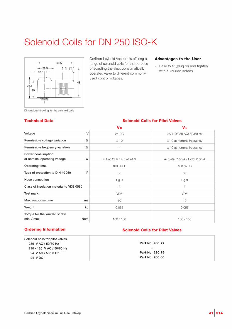
Technical Data Solenoid Coils for Pilot Valves
V= V≈Voltage V
Permissible voltage variation %
Permissible frequency variation %
Power consumption
at nominal operating voltage W
Operating time
Type of protection to DIN 40 050 IP
Hose connection
Class of insulation material to VDE 0580
Test mark
Max. response time ms
Weight kg
Torque for the knurled screw,
min. / max Ncm
24 DC 24/110/230 AC; 50/60 Hz
± 10 ± 10 at nominal frequency
– ± 10 at nominal frequency
4.1 at 12 V / 4.5 at 24 V Actuate: 7.5 VA / Hold: 6.0 VA
100 % ED 100 % ED
65 65
Pg 9 Pg 9
F F
VDE VDE
10 10
0.065 0.055
100 / 150 100 / 150
12,5
35,5
29
48
29,5
60,5
Dimensional drawing for the solenoid coils
Solenoid Coils for DN 250 ISO-K
Oerlikon Leybold Vacuum is offering arange of solenoid coils for the purposeof adapting the electropneumaticallyoperated valve to different commonlyused control voltages.
Advantages to the User
- Easy to fit (plug on and tightenwith a knurled screw)
Part No. 280 77
–
Part No. 280 79
Part No. 280 80
Solenoid coils for pilot valves
230 V AC / 50/60 Hz
110 - 120 V AC / 50/60 Hz
024 V AC / 50/60 Hz
024 V DC
Solenoid Coils for Pilot Valves

C14 42 Oerlikon Leybold Vacuum Full Line Catalog
Purge Gas and Venting Valve
Purge Gas and Venting Valve
Purge Gas and Venting Valve
Purge Gas and Venting Valve
Power Failure Venting Valve
Power Failure Venting Valve
Venting Valve
Venting Valve
Ordering Information
Ordering Information
Technical Data
Ordering Information
Ordering Information
Solenoid Venting Valve
Drive voltage V DC
Power consumption W
Connecting flange DN
Weight, approx. kg
24
4
16 ISO-KF
0.3
Solenoid venting valve,
normally closed
Further vent valves available in US. Please contact your US sales office
Part No. 800120V0011
Power Failure Venting Valve
Technical Data
Drive voltage V DC
Power consumption W
Connecting flange DN
Weight, approx. kg
24
4
16 ISO-KF
0.3
Power failure venting valve,
normally open
Further vent valves available in US. Please contact your US sales office
Part No. 800120V0021
Purge Gas and Venting Valve
Technical Data
Connecting flange DN
Weight, approx. kg
10 ISO-KF
0.7
Purge gas and venting valve, 230 V
0.2 mbar x l x s-1 (12 sccm)
0.4 mbar x l x s-1 (24 sccm)
Purge gas and venting valve, 110 V
0.2 mbar x l x s-1 (12 sccm)
Part No. 855 19
Part No. 855 29
Part No. 190 351 069
Purge Gas and Venting Valve
Technical Data
Connecting flange
Inlet
Outlet
Purge gas pressure, abs. bar
Weight, approx. kg
1/4" pipe
pump specific or DN 16 ISO-KF
1.5 to 6.0
0.5
Purge gas and venting valve, 24 V DC
0.6 mbar x l x s-1 (36 sccm)
Further 0.6 mbar x l x s-1 valves upon request
Part No. 121 33
Special Valves for Turbomolecular Pumps
C1443Oerlikon Leybold Vacuum Full Line Catalog
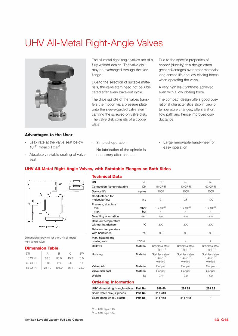
UHV All-Metal Right-Angle Valves
The all-metal right-angle valves are of afully welded design. The valve diskmay be exchanged through the sideflange.
Due to the selection of suitable mate-rials, the valve stem need not be lubri-cated after every bake-out cycle.
The drive spindle of the valves trans-fers the motion via a pressure plateonto the sleeve-guided valve stemcarrying the screwed-on valve disk.The valve disk consists of a copperplate.
Due to the specific properties ofcopper (ductility) this design offersgreat advantages over other materials:long service life and low closing forceswhen operating the valve.
A very high leak tightness achieved,even with a low closing force.
The compact design offers good ope-rational characteristics also in view oftemperature changes, offers a shortflow path and hence improved con-ductance.
Advantages to the User
- Leak rate at the valve seat below10-11 mbar x l x s-1
- Absolutely reliable sealing of valveseat
Technical Data
Dimensional drawing for the UHV all-metal right-angle valve
DN CF
Connection flange rotatable DN
Service life cycles
Conductance for molecularflow l/ s
Pressure, absolutemin. mbarmax. bar
Mounting orientation mm
Bake out temperature without handwheel °C
Bake out temperature with handwheel °C
Max. heating and cooling rate °C/min
Bellows Material
Housing Material
Valve disk Material
Valve disk seal Material
Weight kg
Ordering InformationUHV all-metal right-angle valves Part No.
Spare valve disk, 2 pieces Part No.
Spare hand wheel, plastic Part No.
1) = AISI Type 3162) = AISI Type 304
UHV All-Metal Right-Angle Valves, with Rotatable Flanges on Both Sides
16 40 63
16 CF-R 40 CF-R 63 CF-R
1000 1000 1000
3 38 100
1 x 10-11 1 x 10-11 1 x 10-11
4 4 4
any any any
300 300 300
80 80 80
4 4 2
Stainless steel Stainless steel Stainless steel1.4541 1) 1.4541 1) 1.4541 1)
Stainless steel Stainless steel Stainless steel1.4301 2) 1.4301 2) 1.4301 2)
welded welded welded
Copper Copper Copper
Copper Copper Copper
0.4 2.0 5.0
289 80 289 81 289 82
215 410 – –
215 412 215 442 –
- Simplest operation
- No lubrication of the spindle isnecessary after bakeout
- Large removable handwheel foreasy operation
Dimension TableDN A B C SW
16 CF-R 88.0 38.0 15.5 8.0
40 CF-R 140 63 26 17
63 CF-R 211.0 105.0 36.4 22.0

C14 44 Oerlikon Leybold Vacuum Full Line Catalog
UHV All-Metal Variable Leak Valves
85,5 (3.37") 50 (2")
ø46(1.81")
DN 40 CF-F
DN
16
CF
-R32
,5(1
.28"
) 98,2
(3.
87")
M5
Dimensional drawing for the all-metal variable leakvalves
Technical Data UHV All-Metal Variable Leak Valves
Ordering information
Part No. 289 90
Part No. 289 87
Part No. 289 88
Part No. 290 97
Connection flanges
Input DN
Output DN
Gas flow, min. for
Pure gas mbar x l x s-1
Air mbar x l x s-1
Gas flow
max. mbar x l x s-1
adjustable, max. mbar x l x s-1
Tightness mbar x l x s-1
Pressure absolute
min. mbar
max. bar
Conductance for molecular flow l x s-1
Operating temperature °C
Bakeout temperature °C
Valve seat Material
Valve plate Material
Housing Material
Weight kg
UHV all-metal variable leak valve
Spare valve plate
Spare valve seat
Tool kit for valve seat
UHV All-Metal Variable Leak Valves
16 CF-R
40 CF-R
10-10
10-9
600
100
1 x 10-11
1 x 10⁻¹⁰
30
0,7
200
350
Copper alloy
Sapphire
Stainless steel
1.4

C1445Oerlikon Leybold Vacuum Full Line Catalog
Gate Valves with ISO-KF/CF/ISO-F Flanges
1
Miniature UHV gate valves, ISO-KF flange
Miniature UHV gate valves, CF flange
UHV gate valves
HV gate valves
4
3
2
1
4
3
2
Overview

C14 46 Oerlikon Leybold Vacuum Full Line Catalog
U
V
L
Q
BD
HI
K OA
N
T
M
Dimensional drawing for the miniature UHV gatevalves, articulated lever, ISO-KF flange
Miniature UHV Gate Valves, ISO-KF,Manually Operated (Articulated Lever)
Advantages to the User
- Manually actuated
- Valve technology with only onemoving part
- Equipped with a mechanical posi-tion indicator
- Low particle generating and vibra-tion free actuation
- Compact, light-weight design
Dimension Table
A
B
D
H
I
K
L
M
N
O
Q
T
U
V
DN 16 ISO-KF 25 ISO-KF 40 ISO-KF
mm 40 50 51
mm 30 40 55
mm 15 24 39
mm 17.2 26.2 41.2
mm 3 3 3
mm 25 32 31
mm 100 139 208
mm 15.0 22.0 32.5
mm 39 59 93
mm 30 44 65
mm 25 35 55
mm 37 50 85
mm 25 32 40
mm 30 30 50

Ordering Information
C1447Oerlikon Leybold Vacuum Full Line Catalog
Technical Data Miniature UHV Gate Valve
DN 16 ISO-KF DN 25 ISO-KF DN 40 ISO-KF
Tightness
Body mbar x l x s-1
Valve seat mbar x l x s-1
Pressure range, abs.
High vacuum conductance l x s-1
Differential pressure at the valve disk bar
Max. differential pressure
during opening mbar
Service life until first maintenance cycles
Degassing temperature
for the valve °C
manual open / closed °C
Installation orientation
Weight kg
Material
Valve body
Valve disk
Seal (head, disk)
< 1 x 10⁻⁹ < 1 x 10⁻⁹ < 1 x 10⁻⁹
< 1 x 10⁻⁹ < 1 x 10⁻⁹ < 1 x 10⁻⁹
1 x 10⁻⁷ mbar to 2 bar 1 x 10⁻⁷ mbar to 2 bar 1 x 10⁻⁷ mbar to 2 bar
10 34 140
≤ 2 in both directions ≤ 2 in both directions ≤ 2 in both directions
≤ 30 ≤ 30 ≤ 30
50 000 50 000 50 000
100 / 100 100 / 100 100 / 100
80 80 80
any any any
0.4 0.4 0.7
AlMgSi1 (3.2315) AlMgSi1 (3.2315) AlMgSi1 (3.2315)
AISI 301 (1.4310) AISI 301 (1.4310) AISI 301 (1.4310)
Viton/Viton Viton/Viton Viton/Viton
Part No. 286 06 Part No. 286 08 Part No. 286 09Miniature gate valve, manually operated,
articulated lever
Miniature UHV Gate Valve
DN 16 ISO-KF DN 25 ISO-KF DN 40 ISO-KF

C14 48 Oerlikon Leybold Vacuum Full Line Catalog
U
O
N
T
L
Q
IK
B1H
BD
A
O1
Dimensional drawing for the miniature UHV gate val-ves, manually operated (handwheel), DN 40 ISO-KF
Miniature UHV Gate Valves, ISO-KF and CF,Manually Operated (Handwheel)
G
E x F
2
H1
H
B D
K
C
A
U
N
L
O1
O
Q
T
Dimensional drawing for the miniature UHV gatevalves, manually operated (handwheel), DN 40 CF
Advantages to the User
- Bellows-sealed push gate feed-through
- Valve technology with only onemoving part
- Equipped with a mechanical posi-tion indicator
- Low particle generating and vibra-tion free actuation
- Compact, light-weight design
Dimension Table
A
B
B1
C
D
E x F
G
H
H1
H2
I
K
L
N
O
O1
Q
T
U
DN 40 ISO-KF 40 CF
mm 50 35
mm 72 72
mm 55 –
mm – 58.7
mm 40 40
– 6 x M 6
mm – 7
mm 41.2 –
mm – 48.3
mm – 42
mm 3 –
mm 16 16
mm 198 198
mm 82 82
mm 76 76
mm 70 70
mm 55 55
mm 73 73
mm 45 45
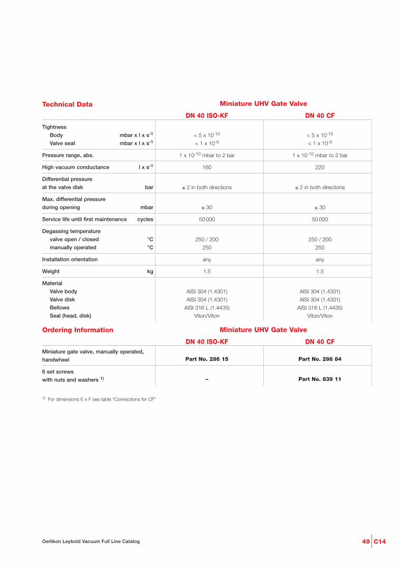
Ordering Information
C1449Oerlikon Leybold Vacuum Full Line Catalog
Technical Data Miniature UHV Gate Valve
DN 40 ISO-KF DN 40 CF
Tightness
Body mbar x l x s-1
Valve seat mbar x l x s-1
Pressure range, abs.
High vacuum conductance l x s-1
Differential pressure
at the valve disk bar
Max. differential pressure
during opening mbar
Service life until first maintenance cycles
Degassing temperature
valve open / closed °C
manually operated °C
Installation orientation
Weight kg
Material
Valve body
Valve disk
Bellows
Seal (head, disk)
< 5 x 10⁻¹⁰ < 5 x 10⁻¹⁰
< 1 x 10⁻⁹ < 1 x 10⁻⁹
1 x 10⁻¹⁰ mbar to 2 bar 1 x 10⁻¹⁰ mbar to 2 bar
160 220
≤ 2 in both directions ≤ 2 in both directions
≤ 30 ≤ 30
50 000 50 000
250 / 200 250 / 200
250 250
any any
1.5 1.5
AISI 304 (1.4301) AISI 304 (1.4301)
AISI 304 (1.4301) AISI 304 (1.4301)
AISI 316 L (1.4435) AISI 316 L (1.4435)
Viton/Viton Viton/Viton
Part No. 286 15 Part No. 286 84
– Part No. 839 11
Miniature gate valve, manually operated,
handwheel
6 set screws
with nuts and washers 1)
1) For dimensions E x F see table “Connections for CF”
Miniature UHV Gate Valve
DN 40 ISO-KF DN 40 CF
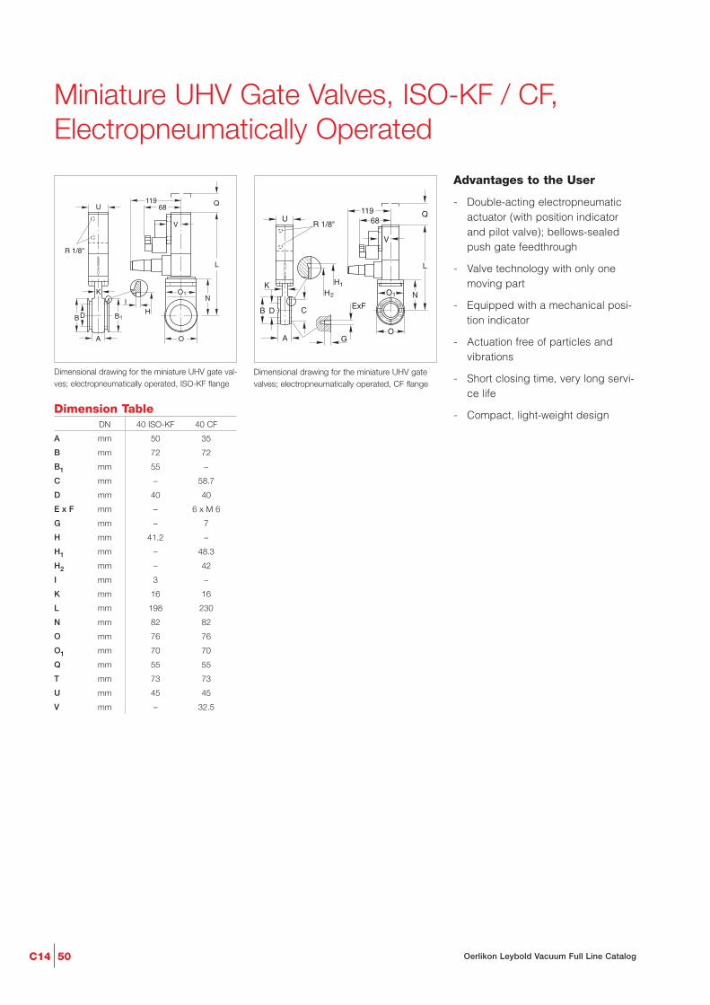
C14 50 Oerlikon Leybold Vacuum Full Line Catalog
O
O1
IK
B1H
BD
A
U
R 1/8"
N
L
11968
Q
V
Dimensional drawing for the miniature UHV gate val-ves; electropneumatically operated, ISO-KF flange
Miniature UHV Gate Valves, ISO-KF / CF,Electropneumatically Operated
O
N
L
G
ExF
O1
Q119
R 1/8" 68
V
2
H1
H
B D
K
C
A
U
Dimensional drawing for the miniature UHV gatevalves; electropneumatically operated, CF flange
Advantages to the User
- Double-acting electropneumaticactuator (with position indicatorand pilot valve); bellows-sealedpush gate feedthrough
- Valve technology with only onemoving part
- Equipped with a mechanical posi-tion indicator
- Actuation free of particles andvibrations
- Short closing time, very long servi-ce life
- Compact, light-weight designDimension Table
A
B
B1
C
D
E x F
G
H
H1
H2
I
K
L
N
O
O1
Q
T
U
V
DN 40 ISO-KF 40 CF
mm 50 35
mm 72 72
mm 55 –
mm – 58.7
mm 40 40
mm – 6 x M 6
mm – 7
mm 41.2 –
mm – 48.3
mm – 42
mm 3 –
mm 16 16
mm 198 230
mm 82 82
mm 76 76
mm 70 70
mm 55 55
mm 73 73
mm 45 45
mm – 32.5

Ordering Information
C1451Oerlikon Leybold Vacuum Full Line Catalog
Technical Data Miniature UHV Gate Valve
DN 40 ISO-KF (Aluminum) DN 40 ISO-KF (Stainless steel) DN 40 CF (Stainless steel)
TightnessBody mbar x l x s-1
Valve seat mbar x l x s-1
Pressure range, abs.
High vacuum conductance l x s-1
Differential pressure at the valve disk bar
Max. differential pressureduring opening mbarat reduced service live bar
Service life until first maintenance cycles
Degassing temperaturevalve open / closed °Cpneumatic actuation °Cposition indicator / pilot valve °C
Warming-up and cooling down speed °C x h-1
Compressed air, min. / max. bar
Closing / opening time s
Pilot valvesupply voltage /power consumption – / W
Switching capacity of the pos. indicatorat 80 °C A
Installation orientation
Weight kg
MaterialValve bodyDiskBellowsSeal (head, disk)
< 1 x 10⁻⁹ < 5 x 10⁻¹⁰ 5 x 10⁻¹⁰
< 1 x 10⁻⁹ < 1 x 10⁻⁹ < 1 x 10⁻⁹
1 x 10⁻⁷ mbar to 2 bar 1 x 10⁻¹⁰ mbar to 2 bar 1 x 10⁻¹⁰ mbar to 2 bar
140 160 220
≤ 2 in both directions ≤ 2 in both directions ≤ 2 in both directions
≤ 30 ≤ 30 ≤ 301 1 1
50 000 50 000 50 000
≤ 100 / 100 ≤ 250 / 200 ≤ 250 / 200≤ 80 ≤ 200 ≤ 200
≤ 80 / 50 80 / 50 80 / 50
80 80 80
4.5 / 7.0 4.5 / 7.0 4.5 / 7.0
1.1 0.7 0.7
24 V DC / 6 or 24 V DC / 6 or 24 V DC / 6 or 230 V AC, 50/60 Hz / 2 230 V AC, 50/60 Hz / 2 230 V AC, 50/60 Hz / 2
0.5 at 50 V AC; 5 at 250 V AC; 5 at 250 V AC;max. 10 W / 3 at 50 V DC 3 at 50 V DC
0.5 at 75 V DC; max. 10 W
any any any
1.2 1.8 1.8
AlMgSi1 (3.2315) AISI 304 (1.4301) AISI 304 (1.4301)AISI 301 (1.4310) AISI 304 (1.4301) AISI 304 (1.4301)
– AISI 316 L (1.4435) AISI 316 L (1.4435)Viton/Viton Metal/Viton Metal/Viton
Part No. 286 54 Part No. 286 36 Part No. 286 99
– Part No. 286 35 Part No. 286 94
– – Part No. 839 11
Miniature gate valve, electropneumatically operated
024 V DC / 6 W230 V AC, 50/60 Hz / 2 W
6 set screws with nuts and washers 1)
1) For dimensions E x F see table “Connections for CF”
Miniature UHV Gate Valve
DN 40 ISO-KF (Aluminum) DN 40 ISO-KF (Stainless steel) DN 40 CF (Stainless steel)

C14 52 Oerlikon Leybold Vacuum Full Line Catalog
U
W
P OK
N
T
L
QV
Dimensional drawing for the HV gate valves; man-ually operated, DN 63 ISO-F and DN 100 ISO-F
HV Gate Valves, ISO-FManually Operated
Advantages to the User
- Cost-effective gate valve for indus-trial applications with elastomer-sealed push gate feedthrough
- Aluminum body
- Slim and light-weight
- Low play in the locked state andlow wear
Dimension Table
K
L
N
O
P
Q
T
U
V
W
DN 63 ISO-F 100 ISO-F 160 ISO-F
mm 36 36 58
mm 329.5 413.0 547.0
mm 155.5 203.5 280.0
mm 100 140 192
mm 48 48 70
mm 25 25 60
mm 174.0 209.5 267.0
mm 43 43 65
mm 94 94 122
mm 75 75 95
U
W
P OK
N
T
L
QV
Dimensional drawing for the HV gate valves;manually operated, DN 160 ISO-F
Connections for ISO-F
A
B
C
D
E x F
G
H
J
M
O1
DN 63 ISO-F 100 ISO-F 160 ISO-F
mm 60 60 70
mm 130 165 235
mm 110 145 200
mm 65 100 150
4 x M8 8 x M8 8 x M10
mm 12 12 16
mm 70 102 153
mm 3 3 5
mm 65.5 83.0 117.5
mm 131 166 237
C
B H
A
M
O1
D
E x FG
J
Connection dimensions for ISO-F flanges (HV gate valves)

Ordering Information
C1453Oerlikon Leybold Vacuum Full Line Catalog
Technical Data HV Gate Valve
DN 63 ISO-F DN 100 ISO-F DN 160 ISO-F
Tightness
Body mbar x l x s-1
Valve seat mbar x l x s-1
Pressure range, abs.
High vacuum conductance l x s-1
Differential pressure at the valve disk bar
Max. differential pressure
during opening mbar
Service life until first maintenance cycles
Degassing temperature
valve °C
manually operated °C
Installation orientation
Weight kg
Material
Valve body
Valve disk
Mechanism
Gaskets (head, disk)
< 1 x 10⁻⁹ < 1 x 10⁻⁹ < 1 x 10⁻⁹
< 1 x 10⁻⁹ < 1 x 10⁻⁹ < 1 x 10⁻⁹
1 x 10⁻⁷ mbar to 1.6 bar 1 x 10⁻⁷ mbar to 1.6 bar 1 x 10⁻⁷ mbar to 1.6 bar
550 2000 6000
1.6 in both directions 1.6 in both directions 1.6 in both directions
≤ 30 ≤ 30 ≤ 30
200000 200000 100000
120 120 120
80 80 80
any any any
3.0 4.5 9.0
AlMg4.5Mn AlMg4.5Mn G-AlSi7Mg
AlSI 304 (1.4301) AlSI 304 (1.4301) AlMgSi1
AlSI 301 (1.4310), AlSI 301 (1.4310), AlSI 301 (1.4310),
AlSI 304 (1.4301), AlSI 304(1.4301), AlSI 304(1.4301),
AlSI 420 (1.4034) AlSI 420 (1.4034) AlSI 420 (1.4034)
Viton Viton Viton
Part No. 286 25 Part No. 286 26 Part No. 215 633
Part No. 839 13 Part No. 839 13 Part No. 210 071
16 16 12
HV gate valve, manually operated
Set screws
with nuts and washers 1)
(Package each containing) pieces
1) For dimensions E x F see table “Connections for ISO-F”
HV Gate Valve
DN 63 ISO-F DN 100 ISO-F DN 160 ISO-F
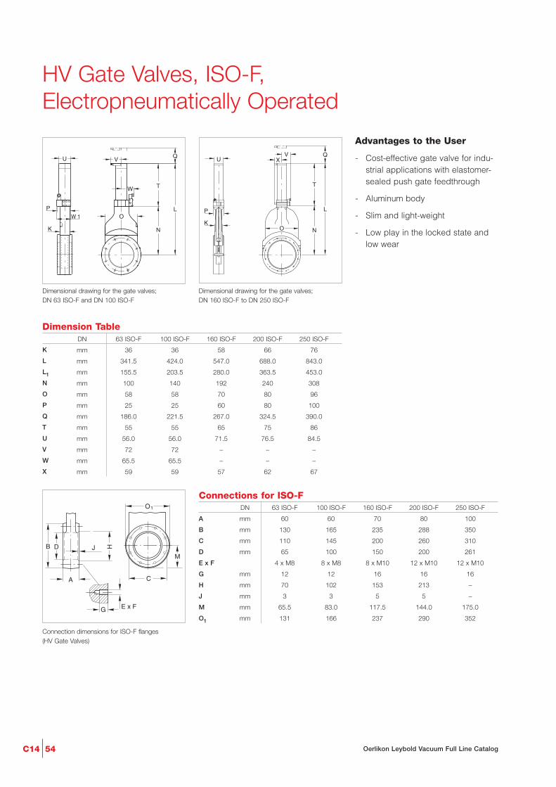
C14 54 Oerlikon Leybold Vacuum Full Line Catalog
U
W
PO
K N
T
L
QV
W 1
Dimensional drawing for the gate valves; DN 63 ISO-F and DN 100 ISO-F
HV Gate Valves, ISO-F, Electropneumatically Operated
Advantages to the User
- Cost-effective gate valve for indu-strial applications with elastomer-sealed push gate feedthrough
- Aluminum body
- Slim and light-weight
- Low play in the locked state andlow wear
Dimension Table
K
L
L1
N
O
P
Q
T
U
V
W
X
DN 63 ISO-F 100 ISO-F 160 ISO-F 200 ISO-F 250 ISO-F
mm 36 36 58 66 76
mm 341.5 424.0 547.0 688.0 843.0
mm 155.5 203.5 280.0 363.5 453.0
mm 100 140 192 240 308
mm 58 58 70 80 96
mm 25 25 60 80 100
mm 186.0 221.5 267.0 324.5 390.0
mm 55 55 65 75 86
mm 56.0 56.0 71.5 76.5 84.5
mm 72 72 – – –
mm 65.5 65.5 – – –
mm 59 59 57 62 67
P
K
U XV Q
T
NO
L
Dimensional drawing for the gate valves; DN 160 ISO-F to DN 250 ISO-F
Connections for ISO-F
A
B
C
D
E x F
G
H
J
M
O1
DN 63 ISO-F 100 ISO-F 160 ISO-F 200 ISO-F 250 ISO-F
mm 60 60 70 80 100
mm 130 165 235 288 350
mm 110 145 200 260 310
mm 65 100 150 200 261
4 x M8 8 x M8 8 x M10 12 x M10 12 x M10
mm 12 12 16 16 16
mm 70 102 153 213 –
mm 3 3 5 5 –
mm 65.5 83.0 117.5 144.0 175.0
mm 131 166 237 290 352
C
B H
A
M
O1
D
E x FG
J
Connection dimensions for ISO-F flanges(HV Gate Valves)

C1455Oerlikon Leybold Vacuum Full Line Catalog
Technical Data HV Gate Valve
DN 63 ISO-F DN 100 ISO-F DN 160 ISO-F DN 200 ISO-F DN 250 ISO-F
< 1 x 10⁻⁹ < 1 x 10⁻⁹ < 1 x 10⁻⁹ < 1 x 10⁻⁹ < 1 x 10⁻⁹
< 1 x 10⁻⁹ < 1 x 10⁻⁹ < 1 x 10⁻⁹ < 1 x 10⁻⁹ < 1 x 10⁻⁹
1 x 10⁻⁷ mbar 1 x 10⁻⁷ mbar 1 x 10⁻⁷ mbar 1 x 10⁻⁷ mbar 1 x 10⁻⁷ mbar
to 1.6 bar to 1.6 bar to 1.6 bar to 1.6 bar to 1.2 bar
550 2000 6000 12000 22000
≤ 1600 in both ≤ 1600 in both ≤ 1600 in both ≤ 1600 in both ≤ 1200 in both
directions directions directions directions directions
≤ 30 ≤ 30 ≤ 30 ≤ 30 ≤ 30
4 / 7 4 / 7 4 / 7 4 / 7 4 / 7
1.5 2.0 2.0 3.0 5.0
200000 200000 100000 100000 100000
120 120 120 120 120
80 80 80 80 80
80 80 80 80 80
50 50 50 50 50
5 at 230 V AC; 5 at 230 V AC; 5 at 230 V AC; 5 at 230 V AC; 5 at 230 V AC;
3 at 50 V DC 3 at 50 V DC 3 at 50 V DC 3 at 50 V DC 3 at 50 V DC
any any any any any
3.0 4.5 9.0 18.0 25.0
AlMg4.5Mn AlMg4.5Mn G-AlSi7Mg G-AlSi7Mg G-AlSi7Mg
AlSI 304 (1.4301) AlSI 304 (1.4301) AlMgSi1, AlMgSi1, AlMgSi1,
AlSI 301 (1.4310), AlSI 301 (1.4310), AlSI 301 (1.4310), AlSI 301 (1.4310), AlSI 301 (1.4310),
AlSI 304 (1.4301), AlSI 304 (1.4301), AlSI 304 (1.4301), AlSI 304 (1.4301), AlSI 304 (1.4301),
AlSI 420 (1.4034) AlSI 420 (1.4034) AlSI 420 (1.4034) AlSI 420 (1.4034) AlSI 420 (1.4034)
Viton Viton Viton Viton Viton
Ordering Information
Part No. Part No.
286 55 286 56 – – –
Part No. Part No. Part No.
– – 215 643 215 644 215 645
Part No. Part No. Part No. Part No. Part No.
286 45 286 46 215 653 215 654 215 655
Part No. Part No. Part No. Part No. Part No.
839 13 839 13 210 071 210 071 210 071
16 16 12 12 12
HV gate valve,
electropneumatically operated
024 V DC / 2.5 W
024 V DC / 6 W
230 V AC, 50 Hz / 7.1 W
Set screws
with nuts and washers 1)
(Package each containing) pieces
1) For dimensions E x F see table “Connections for ISO-F”
HV Gate Valve
DN 63 ISO-F DN 100 ISO-F DN 160 ISO-F DN 200 ISO-F DN 250 ISO-F
Tightness
Body mbar x l x s-1
Valve seat mbar x l x s-1
Pressure range, abs.
High vacuum conductance l x s-1
Differential pressure
at the valve disk, max. mbar
during opening, max. mbar
Compressed air, min. / max. bar
Closing / opening time s
Service life until first maintenance cycles
Degassing temperature
valve °C
pneumatic drive °C
position indicator °C
pilot valve °C
Switching capacity
for the position indicator A
Installation orientation
Weight kg
Material
Valve body
Valve disk
Mechanism
Gaskets (head, disk)

C14 56 Oerlikon Leybold Vacuum Full Line Catalog
U
P
K O1
M
SN
LO
T
U1
VQ
10DN 160/200
Dimensional drawing for the UHV gate valves DN 63 CF to DN 200 CF
UHV Gate Valves, CFManually Operated
C
2
H1
H
13
E x F
A
DB
Connection dimensions for CF flanges (UHV gate valves)
Advantages to the User
- Valve and wheel can be degassedat temperatures up to 250 °C
- Steel body (non-rusting)
- Bellows-sealed push gate feed-through
- Low play in the locked state andlow wear
- Compact
- Mechanically locked in the closedstate
- Mechanical position indicator
Dimension Table
K
L
M
N
O
O1
P
Q
S
T
U
U1
V
DN 63 CF 100 CF 160 CF 200 CF
mm 27 27 27 35
mm 408 462 552 660
mm 57 73 99 125
mm 192 247 336 430
mm 115 145 200 250
mm 112 142 192 240
mm 70 70 70 80
mm 180 220 290 350
mm 11.0 9.0 25.0 38.5
mm 184 184 184 200
mm 70 70 70 90
mm 83 83 83 103
mm 77 77 77 94
Connections for CF
A
B2
C
D
E x F
H1
H2
DN 63 CF 100 CF 160 CF 200 CF
mm 70 70 70 80
mm 113.5 151.6 202.4 253.2
mm 92.1 130.2 181.0 231.8
mm 70 100 150 200
8 x M8 16 x M8 20 x M8 24 x M8
mm 82.5 120.65 171.45 222.3
mm 77.4 115.5 166.0 217.0
Mechanical position indicator

Ordering Information
C1457Oerlikon Leybold Vacuum Full Line Catalog
Technical Data UHV Gate Valve
DN 63 CF DN 100 CF DN 160 CF DN 200 CF
Tightness
Body mbar x l x s-1
Valve seat mbar x l x s-1
Pressure range, abs.
High vacuum conductance l x s-1
Differential pressure at the valve disk bar
Max. differential pressure
during opening mbar
Number of spindle turns for full travel
Service life until first maintenance cycles
Degassing temperature
valve open / closed °C
manually operated °C
Warming-up / cooling down speed
°C x h-1
Installation orientation
Weight kg
Material
Body
Bellows
Mechanism
Gaskets (head, disk)
< 5 x 10⁻¹⁰ < 5 x 10⁻¹⁰ < 5 x 10⁻¹⁰ < 5 x 10⁻¹⁰
< 1 x 10⁻⁹ < 1 x 10⁻⁹ < 1 x 10⁻⁹ < 1 x 10⁻⁹
1 x 10⁻¹⁰ mbar 1 x 10⁻¹⁰ mbar 1 x 10⁻¹⁰ mbar 1 x 10⁻¹⁰ mbar
to 1.6 bar to 1.6 bar to 1.6 bar to 1.6 bar
600 1700 6000 12000
≤ 1.6 in both ≤ 1.6 in both ≤ 1.6 in both ≤ 1.6 in both
directions directions directions directions
≤ 30 ≤ 30 ≤ 30 ≤ 30
10 13 17 17
50 000 50 000 50 000 50 000
250 / 200 250 / 200 250 / 200 250 / 200
250 250 250 250
80 80 80 80
any any any any
9 12 18 28
AlSI 304 (1.4301) AlSI 304 (1.4301) AlSI 304 (1.4301) AlSI 304 (1.4301)
AlSI 316 L (1.4435) AlSI 316 L (1.4435) AlSI 316 L (1.4435) AlSI 316 L (1.4435)
AlSI 304 (1.4301), AlSI 304 (1.4301), AlSI 304 (1.4301), AlSI 304 (1.4301),
AlSI 316 L (1.4404), AlSI 316 L (1.4404), AlSI 316 L (1.4404), AlSI 316 L (1.4404),
AlSI 301 (1.4310), AlSI 301 (1.4310), AlSI 301 (1.4310), AlSI 301 (1.4310),
AlSI 420 (1.4034) AlSI 420 (1.4034) AlSI 420 (1.4034) AlSI 420 (1.4034)
Metal / Viton Metal / Viton Metal / Viton Metal / Viton
Part No. 286 85 Part No. 286 86 Part No. 286 87 Part No. 286 88
Part No. 839 13 Part No. 839 13 2 x Part No. 839 13 2 x Part No. 839 13
UHV Gate Valve
DN 63 CF DN 100 CF DN 160 CF DN 200 CFUHV gate valve, manually operated
16 set screws
with nuts and washers 1)
1) For dimensions E x F see table “Connections for ISO-F”
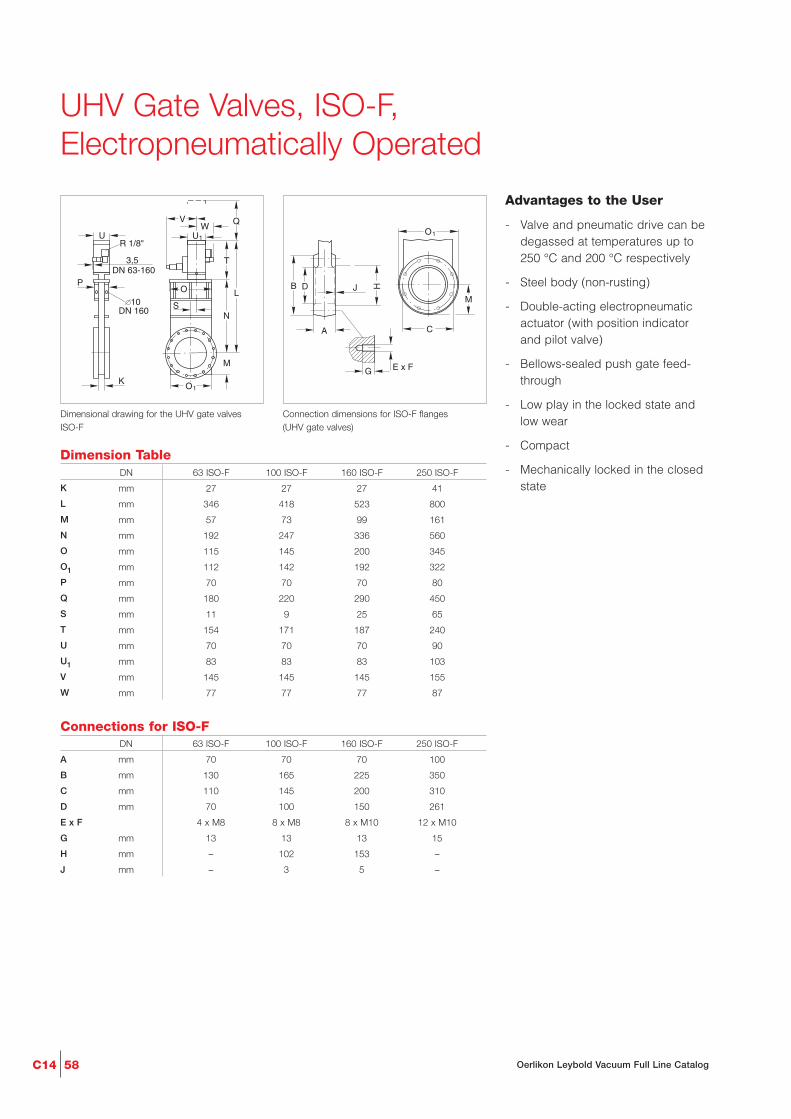
C14 58 Oerlikon Leybold Vacuum Full Line Catalog
U
P
K O1
M
SN
LO
T
Q
U1
VW
10DN 160
3,5DN 63-160
R 1/8"
Dimensional drawing for the UHV gate valves ISO-F
UHV Gate Valves, ISO-F, Electropneumatically Operated
C
B H
A
M
O1
D
E x FG
J
Connection dimensions for ISO-F flanges (UHV gate valves)
Advantages to the User
- Valve and pneumatic drive can bedegassed at temperatures up to250 °C and 200 °C respectively
- Steel body (non-rusting)
- Double-acting electropneumaticactuator (with position indicatorand pilot valve)
- Bellows-sealed push gate feed-through
- Low play in the locked state andlow wear
- Compact
- Mechanically locked in the closedstate
Connections for ISO-F
A
B
C
D
E x F
G
H
J
DN 63 ISO-F 100 ISO-F 160 ISO-F 250 ISO-F
mm 70 70 70 100
mm 130 165 225 350
mm 110 145 200 310
mm 70 100 150 261
4 x M8 8 x M8 8 x M10 12 x M10
mm 13 13 13 15
mm – 102 153 –
mm – 3 5 –
Dimension Table
K
L
M
N
O
O1
P
Q
S
T
U
U1
V
W
DN 63 ISO-F 100 ISO-F 160 ISO-F 250 ISO-F
mm 27 27 27 41
mm 346 418 523 800
mm 57 73 99 161
mm 192 247 336 560
mm 115 145 200 345
mm 112 142 192 322
mm 70 70 70 80
mm 180 220 290 450
mm 11 9 25 65
mm 154 171 187 240
mm 70 70 70 90
mm 83 83 83 103
mm 145 145 145 155
mm 77 77 77 87
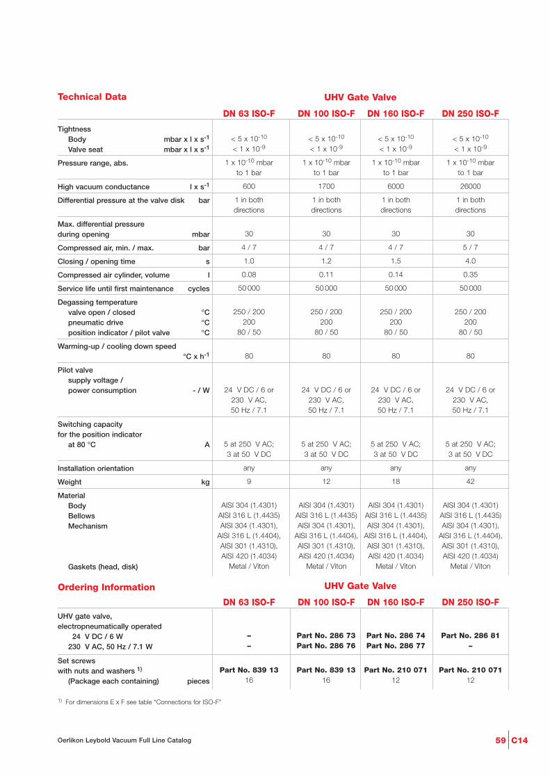
Ordering Information
C1459Oerlikon Leybold Vacuum Full Line Catalog
Technical Data UHV Gate Valve
DN 63 ISO-F DN 100 ISO-F DN 160 ISO-F DN 250 ISO-F
TightnessBody mbar x l x s-1
Valve seat mbar x l x s-1
Pressure range, abs.
High vacuum conductance l x s-1
Differential pressure at the valve disk bar
Max. differential pressure during opening mbar
Compressed air, min. / max. bar
Closing / opening time s
Compressed air cylinder, volume l
Service life until first maintenance cycles
Degassing temperaturevalve open / closed °Cpneumatic drive °Cposition indicator / pilot valve °C
Warming-up / cooling down speed°C x h-1
Pilot valvesupply voltage /power consumption - / W
Switching capacity for the position indicator
at 80 °C A
Installation orientation
Weight kg
MaterialBodyBellowsMechanism
Gaskets (head, disk)
< 5 x 10⁻¹⁰ < 5 x 10⁻¹⁰ < 5 x 10⁻¹⁰ < 5 x 10⁻¹⁰
< 1 x 10⁻⁹ < 1 x 10⁻⁹ < 1 x 10⁻⁹ < 1 x 10⁻⁹
1 x 10⁻¹⁰ mbar 1 x 10⁻¹⁰ mbar 1 x 10⁻¹⁰ mbar 1 x 10⁻¹⁰ mbarto 1 bar to 1 bar to 1 bar to 1 bar
600 1700 6000 26000
1 in both 1 in both 1 in both 1 in bothdirections directions directions directions
30 30 30 30
4 / 7 4 / 7 4 / 7 5 / 7
1.0 1.2 1.5 4.0
0.08 0.11 0.14 0.35
50 000 50 000 50 000 50 000
250 / 200 250 / 200 250 / 200 250 / 200200 200 200 200
80 / 50 80 / 50 80 / 50 80 / 50
80 80 80 80
24 V DC / 6 or 24 V DC / 6 or 24 V DC / 6 or 24 V DC / 6 or230 V AC, 230 V AC, 230 V AC, 230 V AC,50 Hz / 7.1 50 Hz / 7.1 50 Hz / 7.1 50 Hz / 7.1
5 at 250 V AC; 5 at 250 V AC; 5 at 250 V AC; 5 at 250 V AC;3 at 50 V DC 3 at 50 V DC 3 at 50 V DC 3 at 50 V DC
any any any any
9 12 18 42
AlSI 304 (1.4301) AlSI 304 (1.4301) AlSI 304 (1.4301) AlSI 304 (1.4301)AlSI 316 L (1.4435) AlSI 316 L (1.4435) AlSI 316 L (1.4435) AlSI 316 L (1.4435)AlSI 304 (1.4301), AlSI 304 (1.4301), AlSI 304 (1.4301), AlSI 304 (1.4301),
AlSI 316 L (1.4404), AlSI 316 L (1.4404), AlSI 316 L (1.4404), AlSI 316 L (1.4404),AlSI 301 (1.4310), AlSI 301 (1.4310), AlSI 301 (1.4310), AlSI 301 (1.4310),AlSI 420 (1.4034) AlSI 420 (1.4034) AlSI 420 (1.4034) AlSI 420 (1.4034)
Metal / Viton Metal / Viton Metal / Viton Metal / Viton
– Part No. 286 73 Part No. 286 74 Part No. 286 81– Part No. 286 76 Part No. 286 77 –
Part No. 839 13 Part No. 839 13 Part No. 210 071 Part No. 210 07116 16 12 12
UHV gate valve,electropneumatically operated
024 V DC / 6 W230 V AC, 50 Hz / 7.1 W
Set screws with nuts and washers 1)
(Package each containing) pieces
1) For dimensions E x F see table “Connections for ISO-F”
UHV Gate Valve
DN 63 ISO-F DN 100 ISO-F DN 160 ISO-F DN 250 ISO-F

C14 60 Oerlikon Leybold Vacuum Full Line Catalog
U
P
K O1
M
SN
LO
T
Q
U1
VW
10DN 160
3,5DN 63-160
R 1/8"
Dimensional drawing for the UHV gate valves CFelectropneumatically ooperated
UHV Gate Valves, CF, Electropneumatically Operated
C
2
H1
H
13
E x F
A
DB
Connection dimension for CF flanges(UHV Gate Valves)
Advantages to the User
- Double-acting electropneumaticactuator (with position indicatorand pilot valve)
- Bellows-sealed push gate feed-through
- Valve and pneumatic drive can bedegassed at temperatures up to250 °C and 200 °C respectively
- Steel body (non-rusting)
- Low play in the locked state andlow wear
- Compact
- Mechanically locked in the closedstate
Dimension Table
K
L
M
N
O
O1
P
Q
S
T
U
U1
V
W
DN 63 CF 100 CF 160 CF 200 CF
mm 27 27 27 35
mm 346 418 523 630
mm 57 73 99 125
mm 192 247 336 430
mm 115 145 200 250
mm 112 142 192 240
mm 70 70 70 80
mm 180 220 290 350
mm 11 9 25 38,5
mm 154 171 187 200
mm 70 70 70 90
mm 83 83 83 103
mm 145 145 145 155
mm 77 77 77 87
Connections for CF
A
B2
C
D
E x F
H1
H2
DN 63 CF 100 CF 160 CF 200 CF
mm 70 70 70 80
mm 113.5 151.6 202.4 253.2
mm 92.1 130.2 181.0 231.8
mm 70 100 150 200
8 x M8 16 x M8 20 x M8 24 x M8
mm 82.5 120.65 171.45 222.3
mm 77.4 115.5 166.0 217.0

Ordering Information
C1461Oerlikon Leybold Vacuum Full Line Catalog
Technical Data UHV Gate Valve
DN 63 CF DN 100 CF DN 160 CF DN 200 CF
TightnessBody mbar x l x s-1
Valve seat mbar x l x s-1
Pressure range, abs.
High vacuum conductance l x s-1
Differential pressure at the valve disk bar
Max. differential pressure during opening mbar
Compressed air, min. / max. bar
Closing / opening time s
Compressed air cylinder, volume m3
Service life until first maintenance cycles
Degassing temperaturevalve open / closed °Cpneumatic drive °Cposition indicator / pilot valve °C
Warming-up / cooling down speed°C x h-1
Pilot valvesupply voltage /power consumption - / W
Switching capacityfor the position indicator
at 80 °C A
Installation orientation
Weight kg
MaterialBodyBellowsMechanism
Gaskets (head, disk)
< 5 x 10⁻¹⁰ < 5 x 10⁻¹⁰ < 5 x 10⁻¹⁰ < 5 x 10⁻¹⁰
< 1 x 10⁻⁹ < 1 x 10⁻⁹ < 1 x 10⁻⁹ < 1 x 10⁻⁹
1 x 10⁻¹⁰ mbar 1 x 10⁻¹⁰ mbar 1 x 10⁻¹⁰ mbar 1 x 10⁻¹⁰ mbarto 1 bar to 1 bar to 1 bar to 1 bar
600 1700 6000 12000
1 in both 1 in both 1 in both 1 in bothdirections directions directions directions
30 30 30 30
4 / 7 4 / 7 4 / 7 5 / 7
1.0 1.2 1.5 4.0
0.08 0.11 0.14 0.35
50 000 50 000 50 000 50 000
250 / 200 250 / 200 250 / 200 250 / 200200 200 200 200
80 / 50 80 / 50 80 / 50 80 / 50
80 80 80 80
24 V DC / 6 or 24 V DC / 6 or 24 V DC / 6 or 24 V DC / 6 or230 V AC, 230 V AC, 230 V AC, 230 V AC,50 Hz / 7.1 50 Hz / 7.1 50 Hz / 7.1 50 Hz / 7.1
5 at 250 V AC; 5 at 250 V AC; 5 at 250 V AC; 5 at 250 V AC;3 at 50 V DC 3 at 50 V DC 3 at 50 V DC 3 at 50 V DC
any any any any
9 12 18 28
AlSI 304 (1.4301) AlSI 304 (1.4301) AlSI 304 (1.4301) AlSI 304 (1.4301)AlSI 316 L (1.4435) AlSI 316 L (1.4435) AlSI 316 L (1.4435) AlSI 316 L (1.4435)AlSI 304 (1.4301), AlSI 304 (1.4301), AlSI 304 (1.4301), AlSI 304 (1.4301),
AlSI 316 L (1.4404), AlSI 316 L (1.4404), AlSI 316 L (1.4404), AlSI 316 L (1.4404),AlSI 301 (1.4310), AlSI 301 (1.4310), AlSI 301 (1.4310), AlSI 301 (1.4310),AlSI 420 (1.4034) AlSI 420 (1.4034) AlSI 420 (1.4034) AlSI 420 (1.4034)
Metal / Viton Metal / Viton Metal / Viton Metal / Viton
Part No. 286 89 Part No. 286 90 Part No. 286 91 Part No. 286 92
Part No. 286 95 Part No. 286 96 Part No. 286 97 –
Part No. 839 13 Part No. 839 13 2 x Part No. 839 13 2 x Part No. 839 13
UHV gate valve,electropneumatically operated
024 V DC / 6 W230 V AC, 50 Hz / 7.1 W
16 set screws with nuts and washers 1)
1) For dimensions E x F see table “Connections for ISO-F”
UHV Gate Valve
DN 63 CF DN 100 CF DN 160 CF DN 200 CF

OerlikonLeybold Vacuum GmbHBonner Strasse 498D-50968 ColognePhone: +49-(0)221-347 0Fax: +49-(0)221-347 [email protected]
P.R. China
Oerlikon Leybold Vacuum (Tianjin)International Trade Co. Ltd.Beichen EconomicDevelopment Area (BEDA),Shanghai RoadTianjin 300400ChinaSales and Service:Phone: +86-22-2697 0808Fax: +86-22-2697 4061Fax: +86-22-2697 [email protected]@oerlikon.com
Oerlikon Leybold Vacuum (Tianjin) Co. Ltd.Beichen EconomicDevelopment Area (BEDA),Shanghai RoadTianjin 300400ChinaSales and Service:Phone: +86-22-2697 0808Fax: +86-22-2697 4061Fax: +86-22-2697 [email protected]@oerlikon.com
Oerlikon Leybold Vacuum (Tianjin)International Trade Co. Ltd.Shanghai Branch:Add: No.3376 Futedong San Rd.Waigaoqiao FTZShanghai 200131ChinaSales and Service:Phone: +86-21-5064-4666Fax: [email protected]@oerlikon.com
Oerlikon Leybold Vacuum (Tianjin)International Trade Co. Ltd.Guangzhou Office and Service Center1st F, Main BuildingScience City Plaza,No.111 Science Revenue,Guangzhou Science City (GZSC) 510663, Guangzhou,ChinaSales:Phone: +86-20-8723-7873Phone: +86-20-8723-7597Fax: [email protected]@oerlikon.com
Oerlikon Leybold Vacuum (Tianjin)International Trade Co. Ltd.Beijing Branch:1-908, Beijing Landmark Towers8 North Dongsanhuan RoadChaoyang DistrictBeijing 100004ChinaSales:Phone: +86-10-6590-7622Fax: [email protected]
India
Oerlikon Leybold Vacuum India Pvt Ltd.EL-22, J BlockMIDC BhosariPune 411026IndiaSales and Service:Phone: +91-20-3061 60000Fax: +91-20-2712 [email protected]@oerlikon.com
Netherlands
Oerlikon Leybold Vacuum Nederland B.V.Proostwetering 24NNL-3543 AE UtrechtSales and Service: Phone: +31-(30) 242 6330Fax: +31-(30) 242 [email protected]@oerlikon.com
Spain
Oerlikon Leybold Vacuum Spain, S.A.C/. Huelva, 7E-08940 Cornellà de Llobregat(Barcelona)Sales:Phone: +34-93-666 46 16Fax: +34-93-666 43 [email protected]:Phone: +34-93-666 49 51Fax: +34-93-685 40 [email protected]
Sweden
Oerlikon Leybold Vacuum Scandinavia ABBox 9084SE-40092 GöteborgSales and Service:Phone: +46-31-68 84 70Fax: +46-31-68 39 [email protected]/delivery address:Datavägen 57BSE-43632 Askim
Switzerland
Oerlikon Leybold Vacuum Schweiz AGLeutschenbachstrasse 55CH-8050 ZürichSales:Phone: +41-044-308 40 50Fax: +41-044-302 43 [email protected]: Phone: +41-044-308 40 62Fax: +41-044-308 40 [email protected]
USA
Oerlikon Leybold Vacuum USA Inc.5700 Mellon RoadUSA-Export, PA 15632Phone: +1-724-327-5700Fax: [email protected]:Eastern & Central time zonesPhone: +1-724-327-5700Fax: +1-724-333-1217Pacific, Mountain, Alaskan &Hawaiian time zonesPhone: +1-480-752-9191Fax: +1-480-752-9494Service:Phone: +1-724-327-5700Fax: +1-724-325-3577
Belgium
Oerlikon Leybold Vacuum Nederland B.V.Belgisch bijkantoorLeuvensesteenweg 542-9AB-1930 ZaventemSales:Phone: +32-2-711 00 83Fax: +32-2-720 83 [email protected]:Phone: +32-2-711 00 82Fax: +32-2-720 83 [email protected]
France
Oerlikon Leybold Vacuum France S.A.7, Avenue du QuébecZ.A. Courtaboeuf 1 - B.P. 42F-91942 Courtaboeuf CedexSales and Service:Phone: +33-1-69 82 48 00 Fax: +33-1-69 07 57 38 [email protected]
Oerlikon Leybold Vacuum France S.A.Valence Factory640, Rue A. Bergès - B.P. 107F-26501 Bourg-lès-Valence CedexPhone: +33-4-75 82 33 00Fax: +33-4-75 82 92 [email protected]
Great Britain
Oerlikon Leybold Vacuum UK Ltd.Unit 2Silverglade Business ParkLeatherhead RoadUK-Chessington, Surrey KT9 2QLSales:Phone: +44-13-7273 7300Fax: +44-13-7273 [email protected]:Phone: +44-20-8971 7030Fax: +44-20-8971 [email protected]
Italy
Oerlikon Leybold Vacuum Italia S.p.A.8, Via TrasimenoI-20128 MilanoSales:Phone: +39-02-27 22 31Fax: +39-02-27 20 96 [email protected]:Phone: +39-02-27 22 31Fax: +39-02-27 22 32 [email protected]
Oerlikon Leybold Vacuum Italia S.p.A.Field Service BaseZ.I. Le CapanneI-05021 Acquasparta (TR)Phone: +39-0744-93 03 93Fax: +39-0744-94 42 [email protected]
Oerlikon Leybold Vacuum GmbHBonner Strasse 498D-50968 ColognePhone: +49-(0)221-347 1234Fax: +49-(0)221-347 [email protected]
Oerlikon Leybold Vacuum GmbHSales Area North/NortheastBranch Office BerlinBuschkrugallee 331. ObergeschossD-12359 BerlinPhone: +49-(0)30-435 609 0Fax: +49-(0)30-435 609 [email protected]
Oerlikon Leybold Vacuum GmbHSales Area South/SouthwestBranch Office MunichSendlinger Strasse 7D-80331 MunichPhone: +49-(0)89-357 33 9-10Fax: +49-(0)89-357 33 [email protected]@oerlikon.com
Oerlikon Leybold Vacuum GmbHSales Area West & BeneluxBranch Office CologneBonner Strasse 498D-50968 ColognePhone: +49-(0)221-347 1270Fax: +49-(0)221-347 [email protected]
Oerlikon Leybold Vacuum GmbHService Competence CenterEmil-Hoffmann-Strasse 43D-50996 Cologne-SuerthPhone: +49-(0)221-347 1439Fax: +49-(0)221-347 [email protected]
OerlikonLeybold Vacuum GmbHMobil Customer ServiceEmil-Hoffmann-Strasse 43D-50996 Cologne-Suerth Phone: +49-(0)221-347 1765Fax: +49-(0)221-347 [email protected]
Oerlikon Leybold Vacuum GmbH,DresdenZur Wetterwarte 50, Haus 304D-01109 DresdenService:Phone: +49-(0)351-88 55 00Fax: +49-(0)351-88 55 [email protected]
Japan
Oerlikon Leybold VacuumJapan Co., Ltd.Headquarter23-3, Shin-Yokohama3-chomeTobu A.K. Bldg. 4th FloorKohoku-kuYokohama-shi 222-0033Sales:Phone: +81-45-471-3330Fax: [email protected]@oerlikon.com
Oerlikon Leybold VacuumJapan Co., Ltd.Osaka Sales Office5-13, Kawagishi-machiSuita-chiOsaka 564-0037Phone: +81-6-6393-5211Fax: [email protected]@oerlikon.com
Oerlikon Leybold VacuumJapan Co., Ltd.Tsukuba Technical Service CenterKogyo Danchi21, Kasuminosato,Ami-machi, Inashiki-gunIbaraki-ken, 300-0315Service:Phone: +81-298 89 2841Fax: +81-298 89 [email protected]@oerlikon.com
Korea
Oerlikon Leybold Vacuum Korea Ltd.3F. Jellzone 2 Tower, 159-4Jeongja-Dong, Bundang-GuSungnam-Si, Gyeonggi-DoKorea 463-384Sales:Phone: +82-31 785 1367Fax: +82-31 785 1359
623-7, Upsung-DongCheonan-SiChungcheongnam-DoKorea 330-290Service:Phone: +82-41 589 3035Fax: +82-41 588 0166
Singapore
Oerlikon Leybold VacuumSingapore Pte Ltd.1 Science Park RoadSingapore SciencePark 2#02-12, Capricorn BuildingSingapore 117528Sales and Service:Phone: +65-6303 7000Fax: +65-6773 [email protected]@oerlikon.com
Taiwan
Oerlikon Leybold Vacuum Taiwan Ltd.No 416-1, Sec. 3Chung-Hsin Rd., Chu-TungHsin-Chu, Taiwan, R.O.C.Sales and Service:Phone: +886-3-500 1688Fax: +886-3-583 [email protected]@oerlikon.com
Germany Europe Asia
Sales and Service
America
LV_0
8938
_200
7
07
.07
w w w . o e r l i k o n . c o m
OerlikonLeybold Vacuum USA Inc.5700 Mellon RoadUSA-Export, PA 15632Phone: +1-724-327-5700Fax: [email protected]


