Download - c110 - Lincoln Electric Consumables 2014

7/18/2019 c110 - Lincoln Electric Consumables 2014
http://slidepdf.com/reader/full/c110-lincoln-electric-consumables-2014 1/511

7/18/2019 c110 - Lincoln Electric Consumables 2014
http://slidepdf.com/reader/full/c110-lincoln-electric-consumables-2014 2/511

7/18/2019 c110 - Lincoln Electric Consumables 2014
http://slidepdf.com/reader/full/c110-lincoln-electric-consumables-2014 3/511
Table of Contents
Introduction .................................. 14
Stick Electrodes ........................... 19
MIG & TIG...................................... 51
Metal-Cored ................................. 71
Flux-Cored .................................... 85
Submerged Arc ............................ 169
Stainless ..................................... 205
Nickel .......................................... 289
Hardfacing ................................... 315
Aluminum & Cast Iron .................. 371
Pipeliner®
.................................... 383
Power Generation & Nuclear ........ 413
Packaging ................................... 449
Appendix ..................................... 465
(Lot Controlled)
7/18/2019 c110 - Lincoln Electric Consumables 2014
http://slidepdf.com/reader/full/c110-lincoln-electric-consumables-2014 4/5114 ı T H E L I N C O L N E L E C T R I C C O M P A N Y
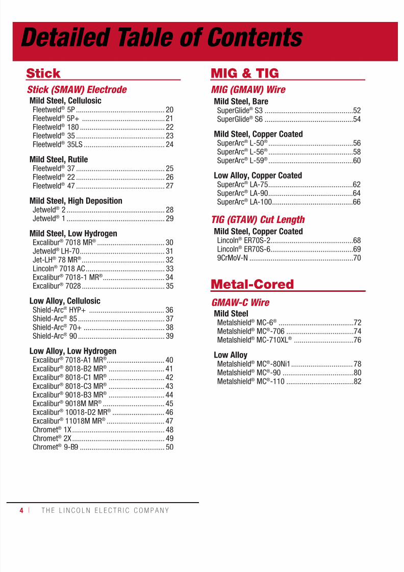
Stick
Stick (SMAW) Electrode
Mild Steel, CellulosicFleetweld® 5P .............................................. 20Fleetweld® 5P+ ...........................................21Fleetweld® 180 ............................................ 22Fleetweld® 35 .............................................. 23Fleetweld® 35LS .......................................... 24
Mild Steel, RutileFleetweld® 37 .............................................. 25Fleetweld® 22 .............................................. 26Fleetweld® 47 .............................................. 27
Mild Steel, High DepositionJetweld® 2 ................................................... 28Jetweld® 1 ................................................... 29
Mild Steel, Low HydrogenExcalibur® 7018 MR® ................................... 30Jetweld® LH-70 ............................................ 31Jet-LH® 78 MR® ........................................... 32Lincoln® 7018 AC ......................................... 33Excalibur® 7018-1 MR® ................................ 34Excalibur® 7028 ........................................... 35
Low Alloy, CellulosicShield-Arc® HYP+ ....................................... 36Shield-Arc® 85 ............................................. 37Shield-Arc® 70+ .......................................... 38Shield-Arc® 90 ............................................. 39
Low Alloy, Low HydrogenExcalibur® 7018-A1 MR® .............................. 40Excalibur® 8018-B2 MR® ............................. 41Excalibur® 8018-C1 MR® ............................. 42Excalibur® 8018-C3 MR® ............................. 43Excalibur® 9018-B3 MR® ............................. 44Excalibur® 9018M MR® ................................ 45Excalibur® 10018-D2 MR® ........................... 46Excalibur® 11018M MR® .............................. 47Chromet® 1X ................................................ 48Chromet® 2X ................................................ 49Chromet® 9-B9 ............................................ 50
MIG & TIG
MIG (GMAW) Wire
Mild Steel, BareSuperGlide® S3 ..............................................52SuperGlide® S6 ..............................................54
Mild Steel, Copper CoatedSuperArc® L-50® ............................................56SuperArc® L-56® ............................................58SuperArc® L-59® ............................................60
Low Alloy, Copper CoatedSuperArc® LA-75 ............................................62
SuperArc®
LA-90 ............................................64SuperArc® LA-100 ..........................................66
TIG (GTAW) Cut Length Mild Steel, Copper CoatedLincoln® ER70S-2...........................................68Lincoln® ER70S-6...........................................699CrMoV-N ......................................................70
Metal-Cored
GMAW-C Wire Mild SteelMetalshield® MC-6® .......................................72Metalshield® MC®-706 ...................................74Metalshield® MC-710XL® ...............................76
Low AlloyMetalshield® MC®-80Ni1 ................................ 78Metalshield® MC®-90 .....................................80Metalshield® MC®-110 ...................................82
Detailed Table of Contents
7/18/2019 c110 - Lincoln Electric Consumables 2014
http://slidepdf.com/reader/full/c110-lincoln-electric-consumables-2014 5/511W E L D I N G C O N S U M A B L E S C A TA L O G ı 5
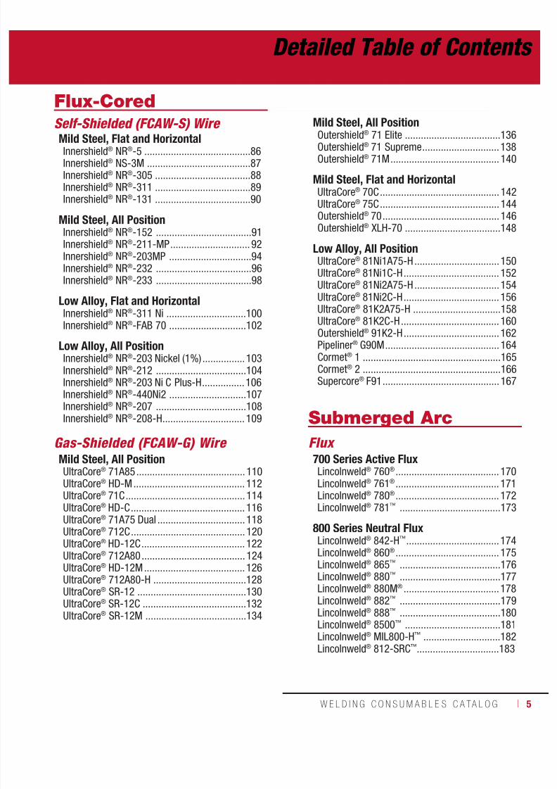
Flux-Cored
Self-Shielded (FCAW-S) Wire
Mild Steel, Flat and HorizontalInnershield® NR®-5 ........................................86Innershield® NS-3M .......................................87Innershield® NR®-305 ....................................88Innershield® NR®-311 ....................................89Innershield® NR®-131 ....................................90
Mild Steel, All PositionInnershield® NR®-152 ....................................91Innershield® NR®-211-MP .............................. 92Innershield® NR®-203MP ...............................94
Innershield®
NR®
-232 ....................................96Innershield® NR®-233 ....................................98
Low Alloy, Flat and HorizontalInnershield® NR®-311 Ni ..............................100Innershield® NR®-FAB 70 .............................102
Low Alloy, All PositionInnershield® NR®-203 Nickel (1%) ................103Innershield® NR®-212 ..................................104Innershield® NR®-203 Ni C Plus-H ................106Innershield® NR®-440Ni2 .............................107
Innershield® NR®-207 ..................................108Innershield® NR®-208-H ............................... 109
Gas-Shielded (FCAW-G) Wire Mild Steel, All PositionUltraCore® 71A85 ......................................... 110UltraCore® HD-M .......................................... 112UltraCore® 71C ............................................. 114UltraCore® HD-C ........................................... 116UltraCore® 71A75 Dual ................................. 118UltraCore® 712C ........................................... 120UltraCore® HD-12C ....................................... 122UltraCore® 712A80 ....................................... 124UltraCore® HD-12M ...................................... 126UltraCore® 712A80-H ...................................128UltraCore® SR-12 .........................................130UltraCore® SR-12C .......................................132UltraCore® SR-12M ......................................134
Mild Steel, All Position
Outershield® 71 Elite ....................................136Outershield® 71 Supreme .............................138Outershield® 71M ......................................... 140
Mild Steel, Flat and HorizontalUltraCore® 70C ............................................. 142UltraCore® 75C ............................................. 144Outershield® 70 ............................................ 146Outershield® XLH-70 ....................................148
Low Alloy, All PositionUltraCore® 81Ni1A75-H ................................150
UltraCore® 81Ni1C-H .................................... 152UltraCore® 81Ni2A75-H ................................154UltraCore® 81Ni2C-H .................................... 156UltraCore® 81K2A75-H .................................158UltraCore® 81K2C-H ..................................... 160Outershield® 91K2-H ....................................162Pipeliner® G90M ........................................... 164Cormet® 1 ....................................................165Cormet® 2 ....................................................166Supercore® F91 ............................................ 167
Submerged Arc
Flux 700 Series Active FluxLincolnweld® 760® ....................................... 170Lincolnweld® 761® ....................................... 171Lincolnweld® 780® ....................................... 172Lincolnweld® 781™ ......................................173
800 Series Neutral FluxLincolnweld® 842-H™ ...................................174Lincolnweld® 860® ....................................... 175Lincolnweld® 865™ ......................................176Lincolnweld® 880™ ......................................177Lincolnweld® 880M® ....................................178Lincolnweld® 882™ ......................................179Lincolnweld® 888™ ......................................180Lincolnweld® 8500™ ....................................181Lincolnweld® MIL800-H™ .............................182Lincolnweld® 812-SRC™ ...............................183
Detailed Table of Contents

7/18/2019 c110 - Lincoln Electric Consumables 2014
http://slidepdf.com/reader/full/c110-lincoln-electric-consumables-2014 6/5116 ı T H E L I N C O L N E L E C T R I C C O M P A N Y
Submerged Arc
Flux
Special Neutral FluxLincolnweld® 960® ....................................... 184Lincolnweld® 980™ ......................................185Lincolnweld® WTX™ .....................................186
Flux for Seam Welding of PipeLincolnweld® 761-Pipe™ ..............................187Lincolnweld® P223™ ....................................188Lincolnweld® SPX80™ ..................................189Lincolnweld® 995N™ ....................................190
High Performance/Alloy FluxLincolnweld® A-XXX 10™ .............................. 191Lincolnweld® MIL800-HPNi™ ........................ 192
Solid Wire Mild SteelLincolnweld® L-50® ...................................... 193Lincolnweld® L-56® ...................................... 193Lincolnweld® L-60........................................194Lincolnweld® L-61® ...................................... 195Lincolnweld® L-S3 .......................................196
Lincolnweld®
LA-71 .....................................196
Low AlloyLincolnweld® L-70........................................197Lincolnweld® LA-75 .....................................197Lincolnweld® LA-81 .....................................198Lincolnweld® LA-82 .....................................198Lincolnweld® LA-84 .....................................199Lincolnweld® LA-85 .....................................199Lincolnweld® LA-90 .....................................200Lincolnweld® LA-92 .....................................200Lincolnweld® LA-93 .....................................201Lincolnweld® LA-100 ...................................201
Cored Wire Mild SteelLincolnweld® LC-72 .....................................202
Low AlloyLincolnweld® LAC-B2 ...................................202Lincolnweld® LAC-Ni2 ..................................203Lincolnweld® LAC-690 .................................204
Stainless
Stick (SMAW) Electrode
Excalibur® 308/308L-15 ............................... 206Excalibur® 308L-16 ...................................... 207Excalibur® 308/308H-16 ..............................208Excalibur® 308/308L-17 ............................... 209Excalibur® 309/309L-15 ............................... 210Excalibur® 309/309L-16 ............................... 211Excalibur® 309/309L-17 ............................... 212Excalibur® 316/316L-15 ............................... 213Excalibur® 316/316L-16 ............................... 214Excalibur® 316/316L-17 ............................... 215Tech-Rod™ 308/308H ..................................216
Tech-Rod™ 308/308L ................................... 217Tech-Rod™ 309/309L ................................... 218Tech-Rod™ 310 ............................................ 219Tech-Rod™ 312 ............................................ 220Tech-Rod™ 316/316L ................................... 221Tech-Rod™ 317L ..........................................222Tech-Rod™ 320LR ........................................ 223Tech-Rod™ 330 ............................................ 224Tech-Rod™ 347 ............................................ 225Tech-Rod™ 385 ............................................ 226Tech-Rod™ 410 ............................................ 227
Tech-Rod™ 410NiMo .................................... 228Tech-Rod™ 630 ............................................229Tech-Rod™ 2209 .......................................... 230Tech-Rod™ 2594 .......................................... 231
MIG (GMAW) Wire
Blue Max® MIG 308LSi .................................232Blue Max® MIG 309LSi .................................234Blue Max® MIG 316LSi .................................236Blue Max® LNM 307 ..................................... 238Blue Max® LNM 347Si .................................. 239Blue Max® LNM 4462 ................................... 240Techalloy® 307 ............................................. 241Techalloy® 308/308H ...................................242Techalloy® 308/308L .................................... 243Techalloy® 308LHS ....................................... 244Techalloy® 309/309L .................................... 245
Detailed Table of Contents

7/18/2019 c110 - Lincoln Electric Consumables 2014
http://slidepdf.com/reader/full/c110-lincoln-electric-consumables-2014 7/511W E L D I N G C O N S U M A B L E S C A TA L O G ı 7
MIG (GMAW) Wire (cont)
Techalloy® 309LHS ....................................... 246Techalloy® 309LMo ......................................247Techalloy® 310 ............................................. 248Techalloy® 312 ............................................. 249Techalloy® 316/316L .................................... 250Techalloy® 316LHS ....................................... 251Techalloy® 317L ...........................................252Techalloy® 320LR ......................................... 253Techalloy® 330 ............................................. 254Techalloy® 347 ............................................. 255Techalloy® 385 ............................................. 256
Techalloy®
409Nb ......................................... 257Techalloy® 410 ............................................. 258Techalloy® 410NiMo ..................................... 259Techalloy® 630 ............................................. 260Techalloy® 2209 ........................................... 261Techalloy® 2594 ........................................... 262
Flux-Cored (FCAW-G) WireUltraCore® FC 308L ......................................263UltraCore® FCP 308L ....................................264UltraCore® FC 309L ......................................266UltraCore® FCP 309L ....................................268
UltraCore® FC 316L ......................................270UltraCore® FCP 316L ....................................272SuperCore® 347 ...........................................274SuperCore® 2205P .......................................275
Submerged Arc WireLincolnweld® 308/308L ................................ 276Lincolnweld® 309/309L ................................ 277Lincolnweld® 316/316L ................................ 278
Submerged Arc FluxLincolnweld® P2000™ ..................................279Lincolnweld® P2007™ ..................................280Lincolnweld® ST-100™ ................................. 281
TIG Cut LengthLincoln® ER308/308L ...................................282Lincoln® ER309/309L ...................................283Lincoln® ER316/316L ...................................284Blue Max® LNT 4462 .................................... 285
Metal-Cored Wire
PRIMALLOY® T-409Ti ....................................286PRIMALLOY® T-439Ti ....................................287
Nickel
Stick (SMAW) Electrode
Tech-Rod™ 55 ..............................................290Tech-Rod™ 99 ..............................................291Tech-Rod™ 112 ............................................292Tech-Rod™ 112LFe ....................................... 293
Tech-Rod™ 117 ............................................294Tech-Rod™ 122 ............................................295Tech-Rod™ 141 ............................................296Tech-Rod™ 182 ............................................297Tech-Rod™ 187 ............................................298Tech-Rod™ 190 ............................................299Tech-Rod™ 276 ............................................300Tech-Rod™ WELD-A ...................................... 301
MIG (GMAW) Wire
Techalloy®
55 ...............................................302Techalloy® 99 ...............................................303Techalloy® 208 .............................................304Techalloy® 276 .............................................305Techalloy® 413 .............................................306Techalloy® 418 .............................................307Techalloy® 606 .............................................308Techalloy® 617 .............................................309Techalloy® 622 .............................................310Techalloy® 625 .............................................311Techalloy® 718 .............................................312Techalloy® 825 .............................................313
Gas-Shielded (FCAW-G) Wire Supercore® 625P .........................................314
Detailed Table of Contents

7/18/2019 c110 - Lincoln Electric Consumables 2014
http://slidepdf.com/reader/full/c110-lincoln-electric-consumables-2014 8/5118 ı T H E L I N C O L N E L E C T R I C C O M P A N Y
Hardfacing
Stick (SMAW) Electrode
Build-UpWearshield® BU ............................................ 316
Metal-to-Metal WearWearshield® MI ............................................317Wearshield® Mangjet® .................................. 318
Severe ImpactWearshield® 15CrMn .................................... 319Wearshield® FROG MANG® ...........................320
Abrasion Plus ImpactWearshield® ABR .......................................... 321Wearshield® 44 ............................................322
Metal-to-Earth WearWearshield® ME ...........................................323
Severe AbrasionWearshield® 60 ............................................324
Maintenance and RepairBlue Max® 2100 ...........................................325Weartech™ WT-1 SMAW ...............................326
Weartech™ WT-12 SMAW .............................327Weartech™ WT-21 SMAW .............................328Weartech™ WT-6 SMAW ...............................329
TIG (GTAW) Cut Lengths Weartech™ WT-1 TIG ....................................330Weartech™ WT-12 TIG ..................................331Weartech™ WT-21 TIG ..................................332Weartech™ WT-6 TIG ....................................333
Metal-Cored (GMAW-C) Wire Build-UpLincore® 60-G ..............................................334Weartech™ WT-1 MIG ...................................335Weartech™ WT-12 MIG .................................336Weartech™ WT-21 MIG .................................337Weartech™ WT-6 MIG ...................................338
Metal-Cored Submerged Arc Wire
Build-UpLincore® 30-S ..............................................339
Metal-to-Metal, Build UpLincore® 32-S ..............................................340Lincore® 35-S ..............................................341
Metal-to-MetalLincore® 40-S ..............................................342Lincore® 42-S ..............................................343
Roll Rebuilding, Build UpLincore® 20 .................................................. 344Lincore® 8620 .............................................. 345Lincore® 4130 .............................................. 346
Roll Rebuilding, Metal-to-MetalLincore® 410 ................................................ 347Lincore® 410NiMo ........................................ 348Lincore® 423L ..............................................349Lincore® 423Cr ............................................350Lincore® 420 ................................................ 351Lincore® 96S ................................................ 352
Lincore®
102W ............................................. 353Lincore® 102HC ...........................................354
Flux-Cored (FCAW-G) Wire Build-UpLincore® BU-G .............................................. 355
Metal-to-MetalLincore® 55-G ..............................................356
Flux-Cored (FCAW-S) Wire
Build-UpLincore® BU..................................................357Lincore® 33 .................................................. 358
Metal-to-MetalLincore® 40-O ..............................................359Lincore® 55 .................................................. 360Lincore® T & D .............................................361
Detailed Table of Contents
7/18/2019 c110 - Lincoln Electric Consumables 2014
http://slidepdf.com/reader/full/c110-lincoln-electric-consumables-2014 9/511W E L D I N G C O N S U M A B L E S C A TA L O G ı 9
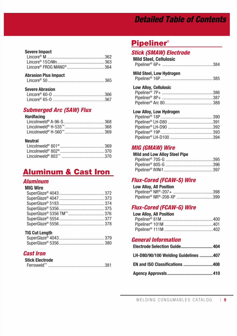
Severe Impact
Lincore®
M ...................................................362Lincore® 15CrMn .......................................... 363Lincore® FROG MANG® ................................. 364
Abrasion Plus ImpactLincore® 50 .................................................. 365
Severe AbrasionLincore® 60-O ..............................................366Lincore® 65-O ..............................................367
Submerged Arc (SAW) Flux
HardfacingLincolnweld® A-96-S .................................... 368Lincolnweld® H-535™ ................................... 368Lincolnweld® H-560™ ................................... 369
NeutralLincolnweld® 801® ....................................... 369Lincolnweld® 802® ....................................... 370Lincolnweld® 803™ ......................................370
Aluminum & Cast IronAluminum MIG WireSuperGlaze® 4043 ........................................ 372SuperGlaze® 4047 ........................................ 373SuperGlaze® 5183 ........................................ 374SuperGlaze® 5356 ........................................ 375SuperGlaze® 5356 TM™ ................................ 376SuperGlaze® 5554 ........................................ 377SuperGlaze® 5556 ........................................ 378
TIG Cut LengthSuperGlaze® 4043 ........................................ 379SuperGlaze® 5356 ........................................ 380
Cast Iron Stick ElectrodeFerroweld™ ..................................................381
Pipeliner ®
Stick (SMAW) Electrode
Mild Steel, CellulosicPipeliner® 6P+ .............................................384
Mild Steel, Low HydrogenPipeliner® 16P .............................................. 385
Low Alloy, CellulosicPipeliner® 7P+ .............................................386Pipeliner® 8P+ .............................................387Pipeliner® Arc 80 .......................................... 388
Low Alloy, Low HydrogenPipeliner® 18P .............................................. 390Pipeliner® LH-D80 ........................................391Pipeliner® LH-D90 ........................................392Pipeliner® 19P .............................................. 393Pipeliner® LH-D100 ......................................394
MIG (GMAW) Wire Mild and Low Alloy Steel PipePipeliner® 70S-G ..........................................395Pipeliner® 80S-G ..........................................396Pipeliner® 80Ni1 ........................................... 397
Flux-Cored (FCAW-S) Wire Low Alloy, All PositionPipeliner® NR®-207+ ...................................398Pipeliner® NR®-208-XP ................................399
Flux-Cored (FCAW-G) Wire Low Alloy, All PositionPipeliner® 81M .............................................400Pipeliner® 101M ...........................................401
Pipeliner® 111M ...........................................402
General Information Electrode Selection Guide ............................404
LH-D80/90/100 Welding Guidelines ............407
EN and ISO Classifications ..........................408
Agency Approvals ........................................ 410
Detailed Table of Contents

7/18/2019 c110 - Lincoln Electric Consumables 2014
http://slidepdf.com/reader/full/c110-lincoln-electric-consumables-2014 10/51110 ı T H E L I N C O L N E L E C T R I C C O M P A N Y
Power Generation& Nuclear (Lot Controlled)
Stick (SMAW) Electrode Mild SteelExcalibur® 7018 MR® N ...............................416
Low AlloyExcalibur® 8018-B2 MR® .............................418Excalibur® 9018-G MR® N ............................420
MIG (GMAW) Wire Mild Steel
SuperArc
®
L-56
®
N ......................................422Low AlloySuperArc® LA-75 .........................................424
Stainless SteelBlue Max® MIG 308L N ................................426Blue Max® MIG 309L N ................................428Blue Max® MIG 316L N ................................430Blue Max® LNM 4462 N ...............................432
TIG (GTAW) Cut Length
Mild SteelLincoln® ER70S-2 ........................................433
Low AlloyLincoln® ER100S-1 ......................................434
Stainless SteelLincoln® ER308/308L N ...............................435Lincoln® ER309/309L N ...............................436Blue Max® LNT 4462 N.................................437
TIG (GTAW) Cut Length - Orbital Mild SteelSuperArc® Orbital TIG L-56® N......................438SuperArc® Orbital TIG L-52 N .......................439
Flux-Cored (FCAW-G) Wire Mild SteelUltraCore® 71A85 ......................................... 440UltraCore® SR-12H ....................................... 442
Submerged Arc (SAW) Flux & Wire Combinations Low AlloyLincolnweld® MIL800-H& Lincolnweld® LA-84 ................................444
Lincolnweld® MIL800-H& Lincolnweld® LA-100 ..............................445
Stainless SteelLincolnweld® P2007& Lincolnweld® 308/308L N .......................446
Lincolnweld® P2007
& Lincolnweld® 309/309L N .......................447Lincolnweld® P2007& Lincolnweld® 316/316L N .......................448
PackagingOptionsTubes, Cans & Cartons..................................450Reels & Stem ...............................................452Spools .......................................................... 454
Coils, Boxes & Bags ...................................... 456Drums & Pails ..............................................458
Storage and HandlingStick Electrode .............................................460Metal-Cored & Flux-Cored Wire ....................462Submerged Arc Flux & Wire ..........................463
Appendix
AWS Classification System Stick ............................................................466MIG, TIG & Metal-Cored ................................ 467Flux-Cored ...................................................468Submerged Arc ............................................470
Detailed Table of Contents
7/18/2019 c110 - Lincoln Electric Consumables 2014
http://slidepdf.com/reader/full/c110-lincoln-electric-consumables-2014 11/511W E L D I N G C O N S U M A B L E S C A TA L O G ı 11
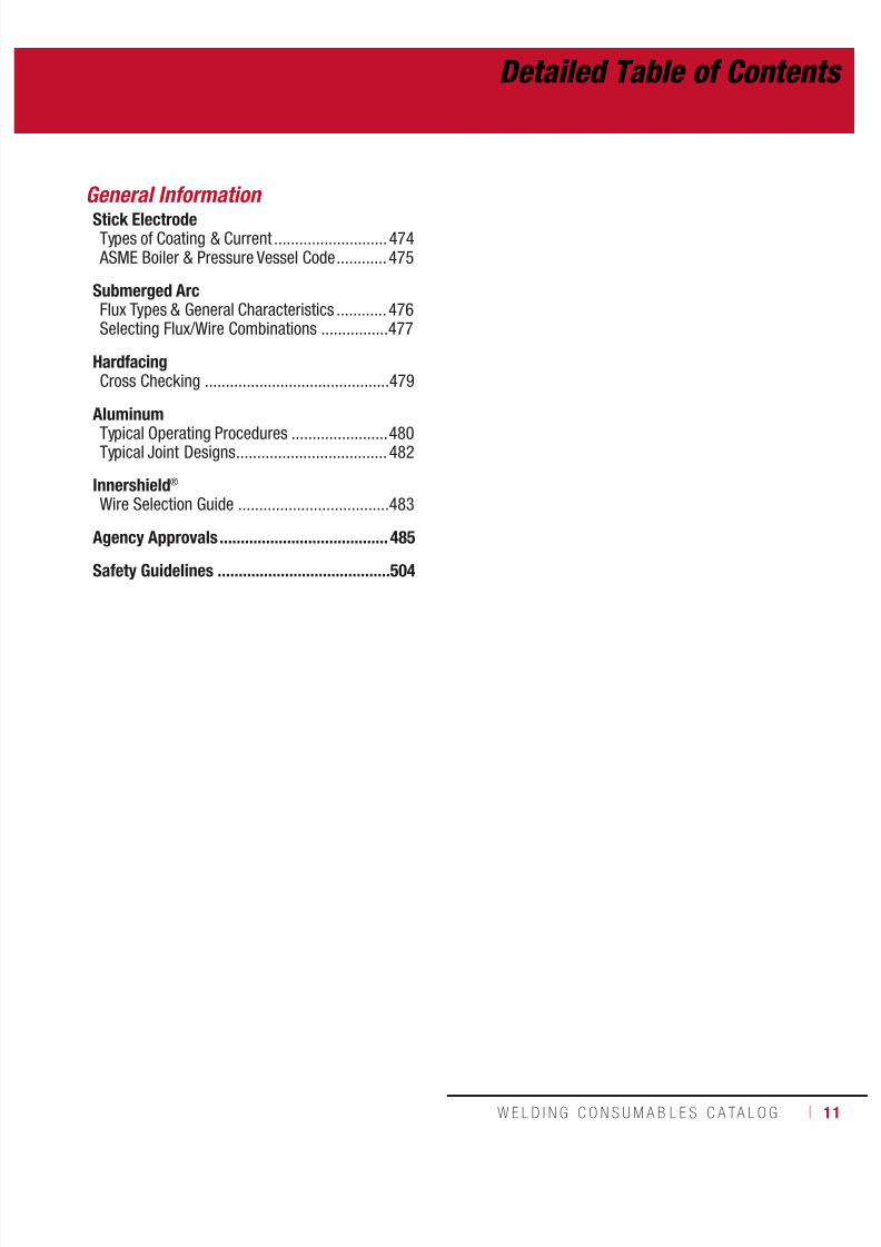
General Information
Stick ElectrodeTypes of Coating & Current ...........................474 ASME Boiler & Pressure Vessel Code ............475
Submerged ArcFlux Types & General Characteristics ............476Selecting Flux/Wire Combinations ................477
HardfacingCross Checking ............................................479
AluminumTypical Operating Procedures .......................480Typical Joint Designs .................................... 482
Innershield®
Wire Selection Guide ....................................483
Agency Approvals ........................................ 485
Safety Guidelines .........................................504
Detailed Table of Contents
7/18/2019 c110 - Lincoln Electric Consumables 2014
http://slidepdf.com/reader/full/c110-lincoln-electric-consumables-2014 12/51112 ı T H E L I N C O L N E L E C T R I C C O M P A N Y
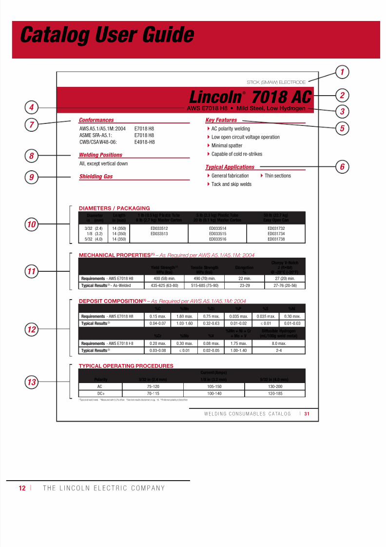
STICK (SMAW) ELECTRODE
(1)Typical all weld metal. (2)Measured with 0.2% offset. (3)See test results disclaimer on pg. 16. (4)Preferred polarity is listed first.
Lincoln ®
7018 AC
Welding Positions
Typical Applications All, except vertical down
General fabrication
Tack and skip welds
Thin sections
AC polarity welding
Low open circuit voltage operation
Minimal spatter
Capable of cold re-strikes
Conformances
AWS E7018 H8 • Mild Steel, Low Hydrogen
Key Features
AWS A5.1/A5.1M: 2004
ASME SFA-A5.1:
CWB/CSA W48-06:
E7018 H8
E7018 H8
E4918-H8
DIAMETERS / PACKAGING
Diameter Length 1 lb (0.5 kg) P last ic Tube6 lb (2.7 kg) Master Carton
5 lb (2.3 kg) Plastic Tube20 lb (9.1 kg) Master Carton
50 lb (22.7 kg)Easy Open Canin (mm) in (mm)
3/32
1/8
5/32
(2.4)
(3.2)
(4.0)
14 (350)
14 (350)
14 (350)
ED033512
ED033513
ED033514
ED033515
ED033516
ED031732
ED031734
ED031738
TYPICAL OPERATING PROCEDURES
Current (Amps)Polarity 3/32 in (2.4 mm) 1/8 in (3.2 mm) 5/32 in (4.0 mm)
AC 75-120 105-150 130-200
DC+ 70-115 100-140 120-185
MECHANICAL PROPERTIES(1) – As Required per AWS A5.1/A5.1M: 2004
Yield Strength(2) Tensile Strength ElongationCharpy V-Notch
J (ft•lbf)MPa (ksi) MPa (ksi) % @ -29°C (-20°F)
Requirements - AWS E7018 H8 400 (58) min. 490 (70) min. 22 min. 27 (20) min.Typical Results(3) - As-Welded 435-625 (63-80) 515-685 (75-90) 23-29 27-76 (20-56)
DEPOSIT COMPOSITION(1) – As Required per AWS A5.1/A5.1M: 2004
%C %Mn %Si %P %S %Ni
Requirements - AWS E7018 H8 0.15 max. 1.60 max. 0.75 max. 0.035 max. 0.035 max. 0.30 max.
Typical Results(3) 0.04-0.07 1.00-1.60 0.32-0.63 0.01-0.02 ≤ 0.01 0.01-0.03
%Cr %Mo %V%Mn + Ni + Cr
+ Mo + VDiffusible Hydrogen
(mL/100g weld metal)
Requirements - AWS E7018 H8 0.20 max. 0.30 max. 0.08 max. 1.75 max. 8.0 max.
Typical Results(3) 0.03-0.08 ≤ 0.01 0.02-0.05 1.00-1.40 2-4
W E L D I N G C O N S U M A B L E S C A TA L O G ı 31
3 4
5
6
7
8
9
1
Shielding Gas
12
13
11
10
2
Catalog User Guide

7/18/2019 c110 - Lincoln Electric Consumables 2014
http://slidepdf.com/reader/full/c110-lincoln-electric-consumables-2014 13/511W E L D I N G C O N S U M A B L E S C A TA L O G ı 13
1. Catalog Section – Refer to the top of each page for a reference to the consumable category.
2. Brand Name – The name of each product appears in the top left or right corner of each page.3. Product Category within Section – Each consumable section of the catalog has
subcategories to further define each product.
4. Classification – AWS or EN classification.
5. Key Features – Top features of each product.
6. Typical Applications – List of where customers typically use product.
7. Conformances – Every specification and conformance to which the product is tested.
8. Welding Positions – Flat and Horizontal or All Position capability.
9. Shielding Gas – Recommended shielding gas in order of performance and(where applicable).
10. Diameters & Packaging Chart – Diameters and packaging available for each product(manufactured to the unit of measurement listed first).
11. Mechanical Properties – Details the AWS mechanical property requirements and typicaltest results for each product’s weld deposit.
12. Chemical Composition – Details the AWS chemical composition content requirements andtypical wire composition or deposit composition results.
13. Typical Operating Procedures – Recommended operating ranges and resulting melt-offand/or deposition rates for each product diameter.
7/18/2019 c110 - Lincoln Electric Consumables 2014
http://slidepdf.com/reader/full/c110-lincoln-electric-consumables-2014 14/51114 ı T H E L I N C O L N E L E C T R I C C O M P A N Y
INTRODUCTION

7/18/2019 c110 - Lincoln Electric Consumables 2014
http://slidepdf.com/reader/full/c110-lincoln-electric-consumables-2014 15/511W E L D I N G C O N S U M A B L E S C A TA L O G ı 15
INTRODUCTION
Lincoln Electric is focused on helping companies make their welding operations moreeffective, more efficient and more profitable. We are dedicated to two equally important goals:exceptional quality and exceptional service. Our field support team — with hundreds of fieldsales engineers and thousands of knowledgeable and responsive Lincoln Electric distributorsin countries all over the world — is the largest in the industry. Lincoln Electric’s innovativethinking, fresh approach to design and a quality-first attitude presents our customers withworldwide strength and support.
Industry-Leading ConsistencyConsistency is critical to the strength and appearance of every weld. Lincoln Electric qualitystarts with superior materials – incoming raw steel slated for use in consumables is analyzedfor chemical composition, checking more than 20 different elements before being cleared for
production. The result is a line of weld consumables that are reliably uniform in diameter andchemical composition. In fact, Lincoln Electric standards are considerably more restrictivethan AWS requirements.
Better Manufacturing SystemsLincoln Electric employs the most technically advanced and carefully monitoredmanufacturing and quality control systems in the welding industry. The result isa line of weld consumables that are reliably uniform.
The Symbol of DependabilityOur stick electrodes have been the number onechoice of fabricators for over a century. They areeasily identified by three dots, which are a symbolof quality, consistency, and unparalleled weldingexpertise. When only the best will do, there is nosubstitute for a Lincoln Electric stick electrode.
ISO 9001:2000
14001:2004
Industry Solutions
Lincoln Electric is committed to developing weldingsolutions that meet the unique needs of ourcustomers, worldwide. Becoming Lincoln Electric’sglobal partner provides your company withspecialized, industry-tested equipment andconsumables created to meet industryspecific welding requirements. Whetheryour company manufactures pipelines,wind towers or offshore oil rigs, choos-ing Lincoln Electric ensures maximum productivity,quality and profitability for our customers.

7/18/2019 c110 - Lincoln Electric Consumables 2014
http://slidepdf.com/reader/full/c110-lincoln-electric-consumables-2014 16/51116 ı T H E L I N C O L N E L E C T R I C C O M P A N Y
INTRODUCTION
Certification to Meet Your Needs
Lincoln Electric offers three levels of Q Lot Certification. While each is indicative of a
unique set of tests, traceabilities and records, all Q Lot Certs share a common heritagegrounded in chemical composition control and Lincoln Electric’s Six Sigma drivenproduction system. No matter which Q Lot Cert you require – from our standard
Q1 Lot® Cert to our comprehensive and exacting Q3 Lot® Cert, you get the peace-of-mind that comes fromknowing that you can count on the performance of your welding consumables.
Q 1 Q 2 Q 3Lincoln Electric standard ISO manufacturing system
Certificates of conformance
Lincoln Electric Q Lot number on product meets AWS A5.01 lot definition requirements
Link Q Lot number to certificate of conformance
Traceable to Lincoln manufacturing date, shift and operator
Recorded flux/mix chemistry
Items below represent additional agency requirements for testing and traceability
Independent verification of records
Recorded steel chemistry
Lot control number per a specification (ASME code, for instance)
Testing per specification (when required)
Independent verification of all tests
Test results traceable to Lincoln archived records
Certification with test results issued to customer
Certification with test results traceable from Lincoln Electric to customer
Lincoln Electric keeps records on file
Certification issued to customer
Lincoln Electric’s Quality System is derived from controlled chemical composition of steel. Our Q Lot System iscomprised of 3 comprehensive levels:
Q1 Lot® – Lincoln Electric’s standard manufacturing and Quality Assurance System. We start by evaluating the
raw materials, analyzing the nose and tail end of each green rod coil for chemical composition ensuring it meetsLincoln’s stringent requirements. Our tight tolerances go beyond AWS requirements to ensure consistency in productchemistry, mechanical properties and operation. Providing traceability to the date of manufacture, operator, line andshift. Examples: Standard commercial products. Products have and AWS certificate of conformance.
Q2 Lot® – Comprised of Q1 Lot®, plus archived lot controlled records of in-process testing and manufacturing,as well as actual and deposit composition test results of the finished product. Providing traceability to the dateof manufacture, operator, line and shift. Examples: Stainless, Nickel, Pipeliner ® and all Batch Managed Inventory.
Products have Certified Material Test Reports (CMTR’s, 3.1)
Q3 Lot® – Comprised of Q2 Lot®, plus special testing requirements and archived records for a specific shipmentor customer. Products can be made to order per customer’s purchase order.
Examples: Military and Nuclear certification. Products have Certified Material Test Reports (CMTR’s, 3.1)
Q Lot Certifications
7/18/2019 c110 - Lincoln Electric Consumables 2014
http://slidepdf.com/reader/full/c110-lincoln-electric-consumables-2014 17/511W E L D I N G C O N S U M A B L E S C A TA L O G ı 17
INTRODUCTION
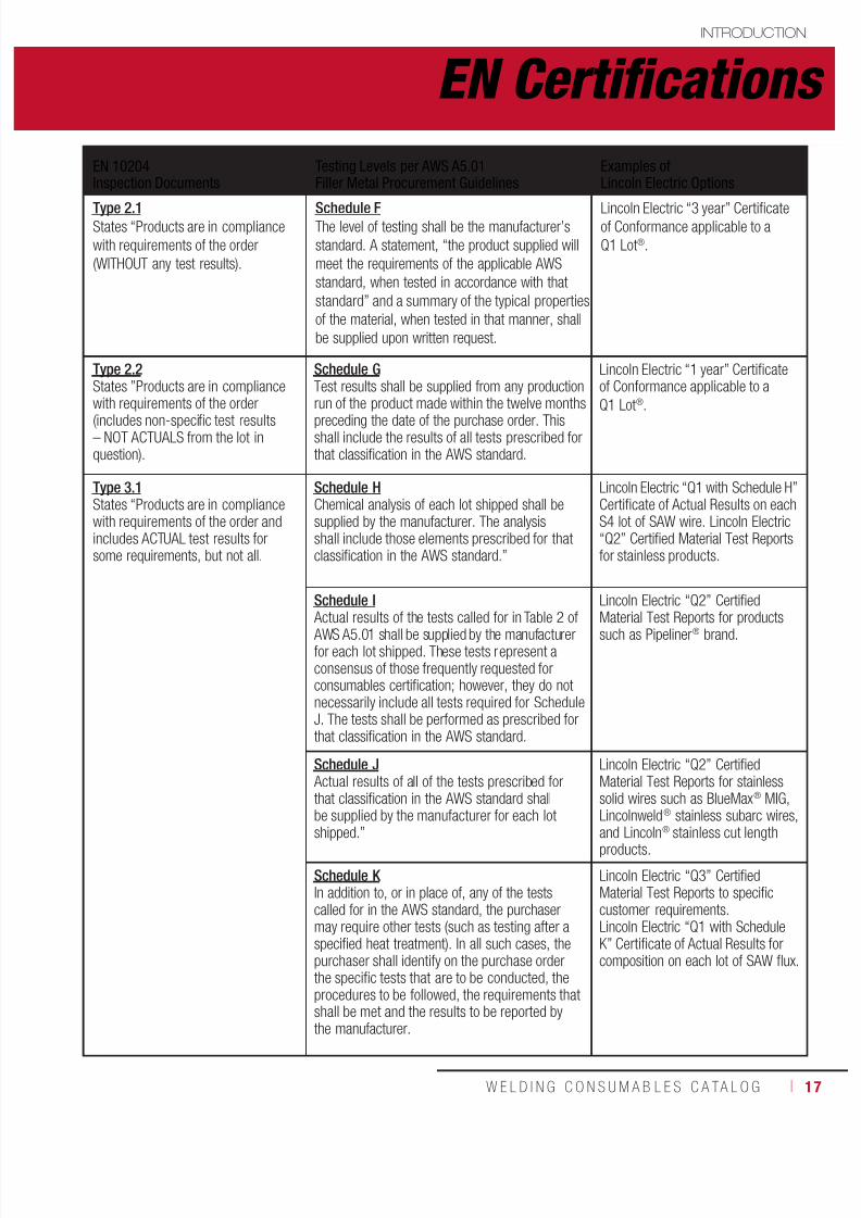
EN 10204Inspection Documents
Testing Levels per AWS A5.01Filler Metal Procurement Guidelines
Examples ofLincoln Electric Options
Type 2.1States “Products are in compliance
with requirements of the order
(WITHOUT any test results).
Schedule FThe level of testing shall be the manufacturer’s
standard. A statement, “the product supplied will
meet the requirements of the applicable AWS
standard, when tested in accordance with that
standard” and a summary of the typical properties
of the material, when tested in that manner, shall
be supplied upon written request.
Lincoln Electric “3 year” Certificateof Conformance applicable to a
Q1 Lot®.
Type 2.2States ”Products are in compliancewith requirements of the order
(includes non-specific test results– NOT ACTUALS from the lot inquestion).
Schedule GTest results shall be supplied from any productionrun of the product made within the twelve months
preceding the date of the purchase order. Thisshall include the results of all tests prescribed forthat classification in the AWS standard.
Lincoln Electric “1 year” Certificateof Conformance applicable to a
Q1 Lot®.
Type 3.1States “Products are in compliancewith requirements of the order andincludes ACTUAL test results forsome requirements, but not all.
Schedule HChemical analysis of each lot shipped shall besupplied by the manufacturer. The analysisshall include those elements prescribed for thatclassification in the AWS standard.”
Lincoln Electric “Q1 with Schedule H”Certificate of Actual Results on eachS4 lot of SAW wire. Lincoln Electric“Q2” Certified Material Test Reportsfor stainless products.
Schedule I
Actual results of the tests called for in Table 2 of AWS A5.01 shall be supplied by the manufacturerfor each lot shipped. These tests represent aconsensus of those frequently requested forconsumables certification; however, they do notnecessarily include all tests required for ScheduleJ. The tests shall be performed as prescribed forthat classification in the AWS standard.
Lincoln Electric “Q2” Certified
Material Test Reports for productssuch as Pipeliner® brand.
Schedule J Actual results of all of the tests prescribed forthat classification in the AWS standard shallbe supplied by the manufacturer for each lot
shipped.”
Lincoln Electric “Q2” CertifiedMaterial Test Reports for stainlesssolid wires such as BlueMax® MIG,Lincolnweld® stainless subarc wires,
and Lincoln® stainless cut lengthproducts.
Schedule K In addition to, or in place of, any of the testscalled for in the AWS standard, the purchasermay require other tests (such as testing after aspecified heat treatment). In all such cases, thepurchaser shall identify on the purchase orderthe specific tests that are to be conducted, theprocedures to be followed, the requirements thatshall be met and the results to be reported bythe manufacturer.
Lincoln Electric “Q3” CertifiedMaterial Test Reports to specificcustomer requirements.Lincoln Electric “Q1 with ScheduleK” Certificate of Actual Results forcomposition on each lot of SAW flux.
EN Certifications
7/18/2019 c110 - Lincoln Electric Consumables 2014
http://slidepdf.com/reader/full/c110-lincoln-electric-consumables-2014 18/51118 ı T H E L I N C O L N E L E C T R I C C O M P A N Y
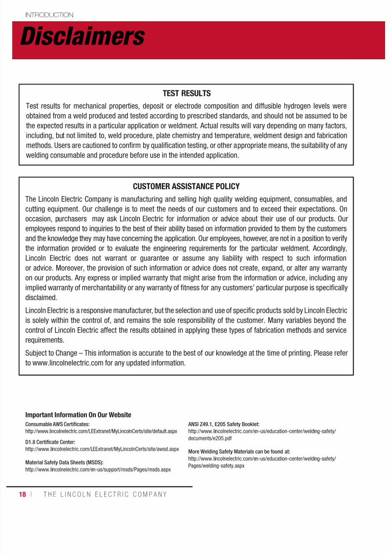
INTRODUCTION
TEST RESULTSTest results for mechanical properties, deposit or electrode composition and diffusible hydrogen levels were
obtained from a weld produced and tested according to prescribed standards, and should not be assumed to be
the expected results in a particular application or weldment. Actual results will vary depending on many factors,
including, but not limited to, weld procedure, plate chemistry and temperature, weldment design and fabrication
methods. Users are cautioned to confirm by qualification testing, or other appropriate means, the suitability of any
welding consumable and procedure before use in the intended application.
CUSTOMER ASSISTANCE POLICYThe Lincoln Electric Company is manufacturing and selling high quality welding equipment, consumables, and
cutting equipment. Our challenge is to meet the needs of our customers and to exceed their expectations. On
occasion, purchasers may ask Lincoln Electric for information or advice about their use of our products. Our
employees respond to inquiries to the best of their ability based on information provided to them by the customers
and the knowledge they may have concerning the application. Our employees, however, are not in a position to verify
the information provided or to evaluate the engineering requirements for the particular weldment. Accordingly,
Lincoln Electric does not warrant or guarantee or assume any liability with respect to such information
or advice. Moreover, the provision of such information or advice does not create, expand, or alter any warranty
on our products. Any express or implied warranty that might arise from the information or advice, including any
implied warranty of merchantability or any warranty of fitness for any customers’ particular purpose is specifically
disclaimed.
Lincoln Electric is a responsive manufacturer, but the selection and use of specific products sold by Lincoln Electric
is solely within the control of, and remains the sole responsibility of the customer. Many variables beyond the
control of Lincoln Electric affect the results obtained in applying these types of fabrication methods and service
requirements.
Subject to Change – This information is accurate to the best of our knowledge at the time of printing. Please refer
to www.lincolnelectric.com for any updated information.
Consumable AWS Certificates:
http://www.lincolnelectric.com/LEExtranet/MyLincolnCerts/site/default.aspx
D1.8 Certificate Center:
http://www.lincolnelectric.com/LEExtranet/MyLincolnCerts/site/awsd.aspx
Material Safety Data Sheets (MSDS):
http://www.lincolnelectric.com/en-us/support/msds/Pages/msds.aspx
ANSI Z49.1, E205 Safety Booklet:
http://www.lincolnelectric.com/en-us/education-center/welding-safety/
documents/e205.pdf
More Welding Safety Materials can be found at:
http://www.lincolnelectric.com/en-us/education-center/welding-safety/
Pages/welding-safety.aspx
Important Information On Our Website
Disclaimers

7/18/2019 c110 - Lincoln Electric Consumables 2014
http://slidepdf.com/reader/full/c110-lincoln-electric-consumables-2014 19/511W E L D I N G C O N S U M A B L E S C A TA L O G ı 19
SMAW CONSUMABLES
STICKMild Steel, CellulosicFleetweld® 5P ................................................20Fleetweld® 5P+ .............................................21
Fleetweld®
180 ..............................................22Fleetweld® 35 ................................................23Fleetweld® 35LS ............................................24
Mild Steel, RutileFleetweld® 37 ................................................25Fleetweld® 22 ................................................26Fleetweld® 47 ................................................27
Mild Steel, High DepositionJetweld® 2 ....................................................28Jetweld® 1 .....................................................29
Mild Steel, Low HydrogenExcalibur® 7018 MR® ..................................... 30Jetweld® LH-70 .............................................31Jet-LH® 78 MR® ............................................. 32Lincoln® 7018 AC ........................................... 33Excalibur® 7018-1 MR® .................................34Excalibur® 7028 .............................................35
Low Alloy, CellulosicShield-Arc® HYP+ .........................................36Shield-Arc® 85 ............................................... 37
Shield-Arc® 70+ ...........................................38Shield-Arc® 90 ............................................... 39
Low Alloy, Low HydrogenExcalibur® 7018-A1 MR® ...............................40Excalibur® 8018-B2 MR® ...............................41Excalibur® 8018-C1 MR® ...............................42Excalibur® 8018-C3 MR® ...............................43Excalibur® 9018-B3 MR® ...............................44Excalibur® 9018M MR® ..................................45Excalibur® 10018-D2 MR® .............................46
Excalibur®
11018M MR®
................................ 47Chromet® 1X .................................................. 48Chromet® 2X .................................................. 49Chromet® 9-B9 ..............................................50
7/18/2019 c110 - Lincoln Electric Consumables 2014
http://slidepdf.com/reader/full/c110-lincoln-electric-consumables-2014 20/51120 ı T H E L I N C O L N E L E C T R I C C O M P A N Y
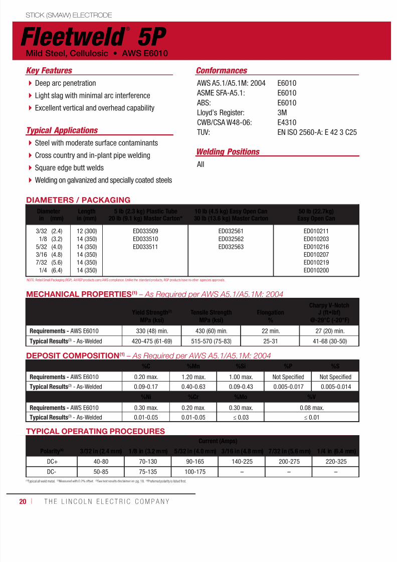
Fleetweld ®
5P STICK (SMAW) ELECTRODE
Welding Positions
Typical Applications
All
Steel with moderate surface contaminants
Cross country and in-plant pipe welding
Square edge butt welds
Welding on galvanized and specially coated steels
Deep arc penetration
Light slag with minimal arc interference Excellent vertical and overhead capability
Key Features Conformances
AWS A5.1/A5.1M: 2004
ASME SFA-A5.1: ABS:
Lloyd’s Register:
CWB/CSA W48-06:
TUV:
E6010
E6010E6010
3M
E4310
EN ISO 2560-A: E 42 3 C25
DIAMETERS / PACKAGING
Diameter Length 5 lb (2.3 kg) Plastic Tube20 lb (9.1 kg) Master Carton*
10 lb (4.5 kg) Easy Open Can30 lb (13.6 kg) Master Carton
50 lb (22.7kg)Easy Open Canin (mm) in (mm)
3/32
1/8
5/32
3/16
7/32
1/4
(2.4)
(3.2)
(4.0)
(4.8)
(5.6)
(6.4)
12 (300)
14 (350)
14 (350)
14 (350)
14 (350)
14 (350)
ED033509
ED033510
ED033511
ED032561
ED032562
ED032563
ED010211
ED010203
ED010216
ED010207
ED010219
ED010200
Mild Steel, Cellulosic • AWS E6010
MECHANICAL PROPERTIES(1) – As Required per AWS A5.1/A5.1M: 2004
Yield Strength(2) Tensile Strength ElongationCharpy V-Notch
J (ft•lbf)MPa (ksi) MPa (ksi) % @-29°C (-20°F)
Requirements - AWS E6010 330 (48) min. 430 (60) min. 22 min. 27 (20) min.
Typical Results(3) - As-Welded 420-475 (61-69) 515-570 (75-83) 25-31 41-68 (30-50)
TYPICAL OPERATING PROCEDURES
Current (Amps)
Polarity(4) 3/32 in (2.4 mm) 1/8 in (3.2 mm) 5/32 in (4.0 mm) 3/16 in (4.8 mm) 7/32 in (5.6 mm) 1/4 in (6.4 mm)
DC+ 40-80 70-130 90-165 140-225 200-275 220-325
DC- 50-85 75-135 100-175 – – –
(1)Typical all weld metal. (2)Measured with 0.2% offset. (3)See test results disclaimer on pg. 18. (4)Preferred polarity is listed first.
NOTE: Retail Small Packaging (RSP). All RSP products carry AWS compliance. Unlike the standard products, RSP products have no other agencies approvals.
DEPOSIT COMPOSITION(1) – As Required per AWS A5.1/A5.1M: 2004
%C %Mn %Si %P %S
Requirements - AWS E6010 0.20 max. 1.20 max. 1.00 max. Not Specified Not Specified
Typical Results(3) - As-Welded 0.09-0.17 0.40-0.63 0.09-0.43 0.005-0.017 0.005-0.014
%Ni %Cr %Mo %V
Requirements - AWS E6010 0.30 max. 0.20 max. 0.30 max. 0.08 max.
Typical Results(3) - As-Welded 0.01-0.05 0.01-0.05 ≤ 0.03 ≤ 0.01
7/18/2019 c110 - Lincoln Electric Consumables 2014
http://slidepdf.com/reader/full/c110-lincoln-electric-consumables-2014 21/511W E L D I N G C O N S U M A B L E S C A TA L O G ı 21
STICK (SMAW) ELECTRODE
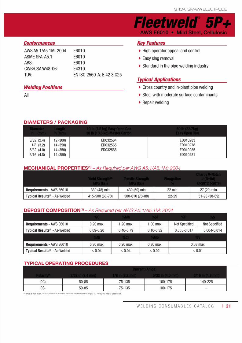
Welding Positions
Typical Applications
All
Cross country and in-plant pipe welding
Steel with moderate surface contaminants
Repair welding
High operator appeal and control
Easy slag removal Standard in the pipe welding industry
Conformances Key Features
AWS A5.1/A5.1M: 2004
ASME SFA-A5.1: ABS:
CWB/CSA W48-06:
TUV:
E6010
E6010E6010
E4310
EN ISO 2560-A: E 42 3 C25
DIAMETERS / PACKAGING
Diameter Length 10 lb (4.5 kg) Easy Open Can30 lb (13.6 kg) Master Carton
50 lb (22.7kg)Easy Open Canin (mm) in (mm)
3/32
1/8
5/32
3/16
(2.4)
(3.2)
(4.0)
(4.8)
12 (300)
14 (350)
14 (350)
14 (350)
ED032564
ED032565
ED032566
ED010283
ED010278
ED010285
ED010281
MECHANICAL PROPERTIES(1) – As Required per AWS A5.1/A5.1M: 2004
Yield Strength(2) Tensile Strength Elongation Charpy V-NotchJ (ft•lbf)MPa (ksi) MPa (ksi) % @-29°C (-20°F)
Requirements - AWS E6010 330 (48) min. 430 (60) min. 22 min. 27 (20) min.
Typical Results(3) - As-Welded 415-500 (60-73) 500-610 (73-88) 22-29 51-93 (38-69)
DEPOSIT COMPOSITION(1) – As Required per AWS A5.1/A5.1M: 2004
%C %Mn %Si %P %S
Requirements - AWS E6010 0.20 max. 1.20 max. 1.00 max. Not Specified Not Specified
Typical Results(3) - As-Welded 0.09-0.20 0.46-0.79 0.10-0.32 0.005-0.017 0.004-0.014
%Ni %Cr %Mo %V
Requirements - AWS E6010 0.30 max. 0.20 max. 0.30 max. 0.08 max.
Typical Results(3) - As-Welded ≤ 0.04 ≤ 0.04 ≤ 0.02 ≤ 0.01
(1)Typical all weld metal. (2)Measured with 0.2% offset. (3)See test results disclaimer on pg. 18. (4)Preferred polarity is listed first.
TYPICAL OPERATING PROCEDURES
Current (Amps)
Polarity(4) 3/32 in (2.4 mm) 1/8 in (3.2 mm) 5/32 in (4.0 mm) 3/16 in (4.8 mm)
DC+ 50-85 75-135 100-175 140-225
DC- 50-85 75-135 100-175 –
Fleetweld ®
5P+ AWS E6010 • Mild Steel, Cellulosic

7/18/2019 c110 - Lincoln Electric Consumables 2014
http://slidepdf.com/reader/full/c110-lincoln-electric-consumables-2014 22/51122 ı T H E L I N C O L N E L E C T R I C C O M P A N Y
STICK (SMAW) ELECTRODE
Fleetweld ®
180
Welding Positions
Typical Applications
All
Small AC welders
Sheet metal Edge, corner and butt joints
Welding on galvanized and specially coated steels
AC polarity welding
Performs on low amperages and OCV Easy to strike arc
Conformances
Mild Steel, Cellulosic • AWS E6011
Key Features
AWS A5.1/A5.1M: 2004
ASME SFA-A5.1:
CWB/CSA W48-06:
E6011
E6011
E4311
DIAMETERS / PACKAGING
Diameter Length 1 lb (0.5 kg) Plastic Tube6 lb (2.7 kg) Master Carton
5 lb (2.3 kg) Plastic Tube20 lb (9.1 kg) Master Carton*
50 lb (22.7 kg)Easy Open Canin (mm) in (mm)
3/32
1/8
5/32
(2.4)
(3.2)
(4.0)
12 (300)
14 (350)
14 (350)
ED033494
ED033495
ED033496
ED033497
ED033498
ED010110
ED010105
ED010114
MECHANICAL PROPERTIES(1) – As Required per AWS A5.1/A5.1M: 2004
Yield Strength(2) Tensile Strength Elongation Charpy V-NotchJ (ft•lbf)MPa (ksi) MPa (ksi) % @-29°C (-20°F)
Requirements - AWS E6011 330 (48) min. 430 (60) min. 22 min. 27 (20) min.
Typical Results(3) - As-Welded 460-490 (67-71) 570-590 (83-86) 22-32 35-72 (26-53)
DEPOSIT COMPOSITION(1) – As Required per AWS A5.1/A5.1M: 2004
%C %Mn %Si %P %S
Requirements - AWS E6011 0.20 max. 1.20 max. 1.00 max. Not Specified Not Specified
Typical Results(3) - As-Welded 0.13-0.20 0.44-0.71 0.23-0.45 0.009-0.014 0.005-0.008
%Ni %Cr %Mo %V
Requirements - AWS E6011 0.30 max. 0.20 max. 0.30 max. 0.08 max.
Typical Results(3) - As-Welded ≤ 0.03 ≤ 0.03 ≤ 0.01 ≤ 0.01
TYPICAL OPERATING PROCEDURES
Current (Amps)
Polarity(4) 3/32 in (2.4 mm) 1/8 in (3.2 mm) 5/32 in (4.0 mm)
AC 40-90 65-120 115-150
DC± 40-80 60-110 105-135
(1)Typical all weld metal. (2)Measured with 0.2% offset. (3)See test results disclaimer on pg. 18. (4)Preferred polarity is listed first.
NOTE: Retail Small Packaging (RSP). All RSP products carry AWS compliance. Unlike the standard products, RSP products have no other agencies approvals.
7/18/2019 c110 - Lincoln Electric Consumables 2014
http://slidepdf.com/reader/full/c110-lincoln-electric-consumables-2014 23/511W E L D I N G C O N S U M A B L E S C A TA L O G ı 23
Fleetweld ®
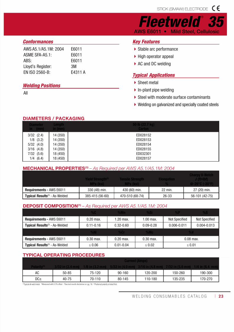
35STICK (SMAW) ELECTRODE
Welding Positions
Typical Applications
All
Sheet metal
In-plant pipe welding
Steel with moderate surface contaminants
Welding on galvanized and specially coated steels
Stable arc performance
High operator appeal AC and DC welding
Conformances Key Features
AWS A5.1/A5.1M: 2004
ASME SFA-A5.1: ABS:
Lloyd’s Register:
EN ISO 2560-B:
E6011
E6011E6011
3M
E4311 A
DIAMETERS / PACKAGING
Diameter Length 50 lb (22.7 kg)Cartonin (mm) in (mm)
3/32
1/8
5/32
3/16
7/32
1/4
(2.4)
(3.2)
(4.0)
(4.8)
(5.6)
(6.4)
14 (350)
14 (350)
14 (350)
14 (350)
18 (450)
18 (450)
ED028152
ED028153
ED028154
ED028155
ED032301
ED028157
AWS E6011 • Mild Steel, Cellulosic
MECHANICAL PROPERTIES
(1)
– As Required per AWS A5.1/A5.1M: 2004
Yield Strength(2) Tensile Strength ElongationCharpy V-Notch
J (ft•lbf)MPa (ksi) MPa (ksi) % @-29°C (-20°F)
Requirements - AWS E6011 330 (48) min. 430 (60) min. 22 min. 27 (20) min.
Typical Results(3) - As-Welded 385-415 (56-60) 470-510 (68-74) 26-33 56-101 (42-75)
DEPOSIT COMPOSITION(1) – As Required per AWS A5.1/A5.1M: 2004
%C %Mn %Si %P %S
Requirements - AWS E6011 0.20 max. 1.20 max. 1.00 max. Not Specified Not Specified
Typical Results
(3)
- As-Welded 0.11-0.16 0.32-0.60 0.09-0.28 0.006-0.011 0.004-0.013%Ni %Cr %Mo %V
Requirements - AWS E6011 0.30 max. 0.20 max. 0.30 max. 0.08 max.
Typical Results(3) - As-Welded ≤ 0.06 0.01-0.04 ≤ 0.02 ≤ 0.01
TYPICAL OPERATING PROCEDURES
Current (Amps)
Polarity(4) 3/32 in (2.4 mm) 1/8 in (3.2 mm) 5/32 in (4.0 mm) 3/16 in (4.8 mm) 7/32 in (5.6 mm) 1/4 in (6.4 mm)
AC 50-85 75-120 90-160 120-200 150-260 190-300
DC± 40-75 70-110 80-145 110-180 135-235 170-270
(1)Typical all weld metal. (2)Measured with 0.2% offset. (3)See test results disclaimer on pg. 18. (4)Preferred polarity is listed first.

7/18/2019 c110 - Lincoln Electric Consumables 2014
http://slidepdf.com/reader/full/c110-lincoln-electric-consumables-2014 24/51124 ı T H E L I N C O L N E L E C T R I C C O M P A N Y
STICK (SMAW) ELECTRODE
Fleetweld ®
35LS
Welding Positions Typical Applications All Tack welding
Steel with moderate surface contaminants
Use for tack welds under Innershield® deposits
Light, easy to remove slag AC and DC welding
Conformances Key Features
AWS A5.1/A5.1M: 2004
ASME SFA-A5.1:CWB/CSA W48-06:
E6011
E6011E4311
Mild Steel, Cellulosic • AWS E6011
DIAMETERS / PACKAGING
Diameter Length 50 lb (22.7 kg)Cartonin (mm) in (mm)
1/8
5/32
(3.2)
(4.0)
14 (350)
14 (350)
ED028158
ED028159
MECHANICAL PROPERTIES(1) – As Required per AWS A5.1/A5.1M: 2004
Yield Strength(2) Tensile Strength ElongationCharpy V-Notch
J (ft•lbf)
MPa (ksi) MPa (ksi) % @-29°C (-20°F)Requirements - AWS E6011 330 (48) min. 430 (60) min. 22 min. 27 (20) min.
Typical Results(3) - As-Welded 400-435 (58-63) 495-560 (72-81) 22-31 29-64 (22-47)
DEPOSIT COMPOSITION(1) – As Required per AWS A5.1/A5.1M: 2004
%C %Mn %Si %P %S
Requirements - AWS E6011 0.20 max. 1.20 max. 1.00 max. Not Specified Not Specified
Typical Results(3) - As-Welded 0.09-0.19 0.75 - 1.10 0.03-0.13 0.007-0.017 0.005-0.011
%Ni %Cr %Mo %VRequirements - AWS E6011 0.30 max. 0.20 max. 0.30 max. 0.08 max.
Typical Results(3) - As-Welded ≤ 0.06 0.01-0.04 ≤ 0.02 0.01 max.
TYPICAL OPERATING PROCEDURES
Current (Amps)
Polarity(4) 1/8 in (3.2 mm) 5/32 in (4.0 mm)
AC 80-130 120-160
DC± 70-120 110-150
(1)Typical all weld metal. (2)Measured with 0.2% offset. (3)See test results disclaimer on pg. 18. (4)Preferred polarity is listed first.

7/18/2019 c110 - Lincoln Electric Consumables 2014
http://slidepdf.com/reader/full/c110-lincoln-electric-consumables-2014 25/511W E L D I N G C O N S U M A B L E S C A TA L O G ı 25
Fleetweld ®
37STICK (SMAW) ELECTRODE
Welding Positions
Typical Applications
All
Sheet metal
Irregular short welds that change positions
Maintenance or repair welding
For use with small AC welders with low OCV
Operable with low amperages on sheet metal
Excellent bead appearance Slag control accommodates vertical downwelding
Conformances Key Features
AWS A5.1/A5.1M: 2004
ASME SFA-A5.1: ABS:
Lloyd’s Register:
DNV Grade:
GL:
BV Grade:
CWB/CSA W48-06:
EN ISO 2560-B:
E6013
E6013E6013
3M
1
1
1
E4313
E4313 A
DIAMETERS / PACKAGING
Diameter Length 1 lb (0.5 kg) Plastic Tube6 lb (2.7 kg) Master Carton
5 lb (2.3 kg) Plastic Tube20 lb (9.1 kg) Master Carton*
50 lb (22.7 kg)Cartonin (mm) in (mm)
5/64
3/32
1/8
5/32
3/16
(2.0)
(2.4)
(3.2)
(4.0)
(4.8)
12 (300)
12 (300)
14 (350)
14 (350)
14 (350)
ED033499
ED033500
ED033501
ED033502
ED033503
ED010170
ED010161
ED010153
ED010165
ED010156
AWS E6013 • Mild Steel, Rutile
MECHANICAL PROPERTIES(1) – As Required per AWS A5.1/A5.1M: 2004
Yield Strength(2) Tensile Strength ElongationCharpy V-Notch
J (ft•lbf)MPa (ksi) MPa (ksi) % @-29°C (-20°F)
Requirements - AWS E6013 330 (48) min. 430 (60) min. 17 min. Not Specified
Typical Results(3) - As-Welded 400-440 (58-64) 460-515 (67-75) 23 37-76 (27-56)
DEPOSIT COMPOSITION(1) – As Required per AWS A5.1/A5.1M: 2004
%C %Mn %Si %P %S
Requirements - AWS E6013 0.20 max. 1.20 max. 1.00 max. Not Specified Not Specified
Typical Results(3) - As-Welded 0.04-0.07 0.32-0.45 0.16-0.24 0.01-0.02 0.01-0.02
%Ni %Cr %Mo %V
Requirements - AWS E6013 0.30 max. 0.20 max. 0.30 max. 0.08 max.
Typical Results(3) - As-Welded ≤ 0.07 0.02 - 0.04 ≤ 0.02 0.01-0.02
TYPICAL OPERATING PROCEDURES
Current (Amps)
Polarity(4) 5/64 in (2.0 mm) 3/32 in (2.4 mm) 1/8 in (3.2 mm) 5/32 in (4.0 mm) 3/16 in (4.8 mm)
AC 50-80 75-115 110-140 160-200 205-260
DC± 45-75 70-105 100-135 145-180 185-235
(1)Typical all weld metal. (2)Measured with 0.2% offset. (3)See test results disclaimer on pg. 18. (4)Preferred polarity is listed first.
NOTE: Retail Small Packaging (RSP). All RSP products carry AWS compliance. Unlike the standard products, RSP products have no other agencies approvals.
7/18/2019 c110 - Lincoln Electric Consumables 2014
http://slidepdf.com/reader/full/c110-lincoln-electric-consumables-2014 26/51126 ı T H E L I N C O L N E L E C T R I C C O M P A N Y
STICK (SMAW) ELECTRODE
(1)Typical all weld metal. (2)Measured with 0.2% offset. (3)See test results disclaimer on pg. 18. (4)Preferred polarity is listed first.
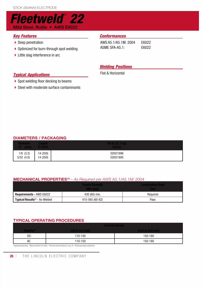
Fleetweld ®
22
Welding Positions
Typical Applications Flat & Horizontal
Spot welding floor decking to beams
Steel with moderate surface contaminants
Deep penetration
Optimized for burn-through spot welding Little slag interference in arc
Conformances Key Features
AWS A5.1/A5.1M: 2004
ASME SFA-A5.1:
E6022
E6022
Mild Steel, Rutile • AWS E6022
DIAMETERS / PACKAGING
Diameter Length 50 lb (22.7 kg)
Cartonin (mm) in (mm)1/8
5/32
(3.2)
(4.0)
14 (350)
14 (350)
ED021896
ED021895
MECHANICAL PROPERTIES(1) – As Required per AWS A5.1/A5.1M: 2004
Tensile Strength Longitudinal BendMPa (ksi) Test
Requirements - AWS E6022 430 (60) min. Required
Typical Results(3) - As-Welded 415-565 (60-82) Pass
TYPICAL OPERATING PROCEDURES
Current (Amps)
Polarity(4) 1/8 in (3.2 mm) 5/32 in (4.0 mm)
DC- 110-150 150-180
AC 110-150 150-180
7/18/2019 c110 - Lincoln Electric Consumables 2014
http://slidepdf.com/reader/full/c110-lincoln-electric-consumables-2014 27/511W E L D I N G C O N S U M A B L E S C A TA L O G ı 27
STICK (SMAW) ELECTRODE
Fleetweld ®
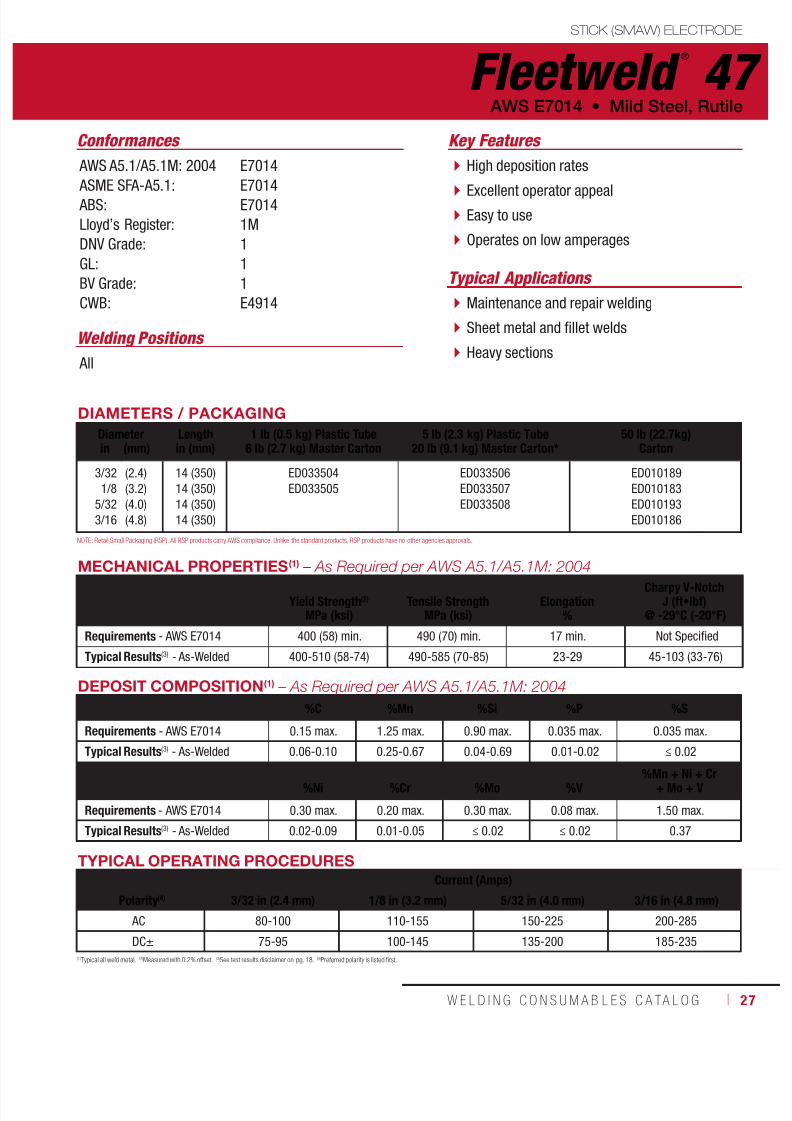
47
Welding Positions
Typical Applications
All
Maintenance and repair welding
Sheet metal and fillet welds
Heavy sections
High deposition rates
Excellent operator appeal Easy to use
Operates on low amperages
Conformances Key Features
AWS A5.1/A5.1M: 2004
ASME SFA-A5.1: ABS:
Lloyd’s Register:
DNV Grade:
GL:
BV Grade:
CWB:
E7014
E7014E7014
1M
1
1
1
E4914
DIAMETERS / PACKAGING
Diameter Length 1 lb (0.5 kg) Plastic Tube6 lb (2.7 kg) Master Carton
5 lb (2.3 kg) Plastic Tube20 lb (9.1 kg) Master Carton*
50 lb (22.7kg)Cartonin (mm) in (mm)
3/32
1/8
5/32
3/16
(2.4)
(3.2)
(4.0)
(4.8)
14 (350)
14 (350)
14 (350)
14 (350)
ED033504
ED033505
ED033506
ED033507
ED033508
ED010189
ED010183
ED010193
ED010186
AWS E7014 • Mild Steel, Rutile
TYPICAL OPERATING PROCEDURES
Current (Amps)
Polarity(4) 3/32 in (2.4 mm) 1/8 in (3.2 mm) 5/32 in (4.0 mm) 3/16 in (4.8 mm)
AC 80-100 110-155 150-225 200-285
DC± 75-95 100-145 135-200 185-235
MECHANICAL PROPERTIES(1) – As Required per AWS A5.1/A5.1M: 2004
Yield Strength(2) Tensile Strength ElongationCharpy V-Notch
J (ft•lbf)MPa (ksi) MPa (ksi) % @ -29°C (-20°F)
Requirements - AWS E7014 400 (58) min. 490 (70) min. 17 min. Not Specified
Typical Results(3) - As-Welded 400-510 (58-74) 490-585 (70-85) 23-29 45-103 (33-76)
DEPOSIT COMPOSITION(1) – As Required per AWS A5.1/A5.1M: 2004
%C %Mn %Si %P %S
Requirements - AWS E7014 0.15 max. 1.25 max. 0.90 max. 0.035 max. 0.035 max.
Typical Results(3) - As-Welded 0.06-0.10 0.25-0.67 0.04-0.69 0.01-0.02 ≤ 0.02
%Ni %Cr %Mo %V%Mn + Ni + Cr
+ Mo + V
Requirements - AWS E7014 0.30 max. 0.20 max. 0.30 max. 0.08 max. 1.50 max.
Typical Results(3) - As-Welded 0.02-0.09 0.01-0.05 ≤ 0.02 ≤ 0.02 0.37
(1)Typical all weld metal. (2)Measured with 0.2% offset. (3)See test results disclaimer on pg. 18. (4)Preferred polarity is listed first.
NOTE: Retail Small Packaging (RSP). All RSP products carry AWS compliance. Unlike the standard products, RSP products have no other agencies approvals.

7/18/2019 c110 - Lincoln Electric Consumables 2014
http://slidepdf.com/reader/full/c110-lincoln-electric-consumables-2014 28/51128 ı T H E L I N C O L N E L E C T R I C C O M P A N Y
STICK (SMAW) ELECTRODE
Jetweld ®
2
Welding Positions
Typical Applications
Flat & Horizontal
Multiple pass welding
Fast-fill single pass welds
Fillet and lap welds
High deposition rates
Smooth bead appearance Shallow penetration for minimal dilution
Conformances
Mild Steel, High Deposition • AWS E6027
Key Features
AWS A5.1/A5.1M: 2004
ASME SFA-A5.1: ABS:
Lloyd’s Register:
DNV Grade:
GL:
BV Grade:
CWB/CSA W48-06:
EN ISO 2560-B:
E6027
E6027E6027
3M
3
3
3
E4327
E4327 A
DIAMETERS / PACKAGING
Diameter Length 50 lb (22.7 kg)Cartonin (mm) in (mm)
3/16
1/4
(4.8)
(6.4)
18 (450)
18 (450)
ED010501
ED010500
TYPICAL OPERATING PROCEDURES
Current (Amps)
Polarity(4) 3/16 in (4.8 mm) 1/4 in (6.4 mm)
AC 250-300 350-450
DC± 230-270 315-405
MECHANICAL PROPERTIES(1) – As Required per AWS A5.1/A5.1M: 2004
Yield Strength(2) Tensile Strength ElongationCharpy V-Notch
J (ft•lbf)MPa (ksi) MPa (ksi) % @ -29°C (-20°F)
Requirements - AWS E6027 330 (48) min. 430 (60) min. 22 min. 27 (20) min.
Typical Results(3) - As-Welded 365-395 (53-57) 435-470 (63-68) 26-34 53-80 (39-60)
DEPOSIT COMPOSITION(1) – As Required per AWS A5.1/A5.1M: 2004
%C %Mn %Si %P %S
Requirements - AWS E6027 0.20 max. 1.20 max. 1.00 max. Not Specified Not Specified
Typical Results(3) - As-Welded 0.02-0.07 0.70-1.10 0.12-0.41 0.016-0.024 0.005-0.013
%Ni %Cr %Mo %V
Requirements - AWS E6027 0.30 max. 0.20 max. 0.30 max. 0.08 max.
Typical Results(3) - As-Welded 0.03-0.07 0.02-0.05 0.01-0.04 ≤ 0.01
(1)Typical all weld metal. (2)Measured with 0.2% offset. (3)See test results disclaimer on pg. 18. (4)Preferred polarity is listed first.

7/18/2019 c110 - Lincoln Electric Consumables 2014
http://slidepdf.com/reader/full/c110-lincoln-electric-consumables-2014 29/511W E L D I N G C O N S U M A B L E S C A TA L O G ı 29
Jetweld ®
1STICK (SMAW) ELECTRODE
Welding Positions
Typical Applications
Flat & Horizontal
Large welds
Slightly downhill (15° max) positions
Multiple pass welding
High deposition rates
Smooth bead appearance Minimal spatter
Shallow penetration
Conformances
AWS E7024-1 • Mild Steel, High Deposition
Key Features
AWS A5.1/A5.1M: 2004
ASME SFA-A5.1: ABS:
Lloyd’s Register:
DNV Grade:
GL:
BV Grade:
CWB/CSA W48-06:
EN ISO 2560-B:
E7024-1
E7024-1E7024-1
1M
1
1
1
E4924-1
E4924-1 A
DIAMETERS / PACKAGING
Diameter Length 50 lb (22.7 kg)Cartonin (mm) in (mm)
1/8
5/32
3/16
7/32
1/4
(3.2)
(4.0)
(4.8)
(5.6)
(6.4)
14 (350)
14 (350)
18 (450)
18 (450)
18 (450)
ED010362
ED010372
ED010366
ED010375
ED010360
TYPICAL OPERATING PROCEDURES
Current (Amps)
Polarity(4) 1/8 in (3.2 mm) 5/32 in (4.0 mm) 3/16 in (4.8 mm) 7/32 in (5.6 mm) 1/4 in (6.4 mm)
AC 115-175 180-240 240-300 300-380 340-440
DC± 100-160 160-215 220-280 270-340 320-400
MECHANICAL PROPERTIES(1)
Yield Strength(2) Tensile Strength ElongationCharpy V-Notch
J (ft•lbf)MPa (ksi) MPa (ksi) % @ -18°C (0°F)
Requirements - AWS E7024-1 400 (58) min. 490 (70) min. 22 min. 27 (20) min.
Typical Results(3) - As-Welded 455-490 (66-71) 530-565 (77-86) 22-31 27-60 (20-44)
DEPOSIT COMPOSITION(1) – As Required per AWS A5.1/A5.1M: 2004
%C %Mn %Si %P %S
Requirements - AWS E7024-1 0.15 max. 1.25 max. 0.90 max. 0.035 max. 0.035 max.
Typical Results(3) - As-Welded 0.03-0.06 0.63-1.02 0.13-0.68 0.010-0.022 0.005-0.011
%Ni %Cr %Mo %V%Mn + Ni + Cr
+ Mo + V
Requirements - AWS E7024-1 0.30 max. 0.20 max. 0.30 max. 0.08 max. 1.50 max.
Typical Results(3) - As-Welded ≤ 0.06 0.01-0.05 ≤ 0.02 0.03 max. 0.75
(1)Typical all weld metal. (2)Measured with 0.2% offset. (3)See test results disclaimer on pg. 18. (4)Preferred polarity is listed first.

7/18/2019 c110 - Lincoln Electric Consumables 2014
http://slidepdf.com/reader/full/c110-lincoln-electric-consumables-2014 30/51130 ı T H E L I N C O L N E L E C T R I C C O M P A N Y
STICK (SMAW) ELECTRODE
Excalibur ®
7018 MR ®
Welding Positions
Typical Applications
All, except vertical down
Mild steel
Power generation
Petrochemical
Pressure vessels
Pressure piping
Premium arc performance
Square coating burn-off Easy strike and re-strike
Effortless slag removal
Minimal spatter for enhanced operabilityand clean weld surface
Conformances
Mild Steel, Low Hydrogen • AWS E7018 H4R
Key Features
AWS A5.1/A5.1M: 2004
ASME SFA-A5.1: ABS:
Lloyd’s Register:
DNV Grade:
GL:
BV Grade:
CWB/CSA W48-06:
EN ISO 2560-B:
E7018 H4R
E7018 H4R3Y H5
3YM H5
3 YH5
3YH5
3YHHH
E4918
E4918 A H5
DIAMETERS / PACKAGING
Diameter Length 1 lb (0.5 kg) Plastic Tube6 lb (2.7 kg) Master Carton
10 lb (4.5 kg) Easy Open Can30 lb (13.6 kg) Master Carton
50 lb (22.7kg)Easy Open Canin (mm) in (mm)
3/32
1/8
5/32
3/16
7/32
1/4
(2.4)
(3.2)
(4.0)
(4.8)
(5.6)
(6.4)
14 (350)
14 (350)
14 (350)
14 (350)
18 (450)
18 (450)
ED032086
ED031468
ED032588
ED032589
ED032590
ED028280
ED028281
ED028282
ED028283
ED028917
ED028918
TYPICAL OPERATING PROCEDURES
Current (Amps)
Polarity(4) 3/32 in (2.4 mm) 1/8 in (3.2 mm) 5/32 in (4.0 mm) 3/16 in (4.8 mm) 7/32 in (5.6 mm) 1/4 in (6.4 mm)
DC+ 70-110 90-160 130-210 180-300 250-330 300-400
AC 80-120 100-160 140-210 200-300 270-370 325-420
MECHANICAL PROPERTIES(1) – As Required per AWS A5.1/A5.1M: 2004
Yield Strength(2) Tensile Strength ElongationCharpy V-Notch
J (ft•lbf)MPa (ksi) MPa (ksi) % @ -29°C (-20°F)
Requirements - AWS E7018 H4R 400 (58) min. 490 (70) min. 22 min. 27 (20) min.
Typical Results(3) - As-Welded 430-510 (62-74) 510-605 (74-88) 25-37 121-332 (89-246)
DEPOSIT COMPOSITION(1) – As Required per AWS A5.1/A5.1M: 2004
%C %Mn %Si %P %S %Ni
Requirements - AWS E7018 H4R 0.15 max. 1.60 max. 0.75 max. 0.035 max. 0.035 max. 0.30 max.
Typical Results
(3)
0.03-0.08 1.01-1.55 0.34-0.68 0.01-0.02 ≤ 0.01 0.01-0.06
%Cr %Mo %V%Mn + Ni + Cr
+ Mo + VDiffusible Hydrogen
(mL/100g weld metal)
Requirements - AWS E7018 H4R 0.20 max. 0.30 max. 0.08 max. 1.75 max. 4.0 max.
Typical Results(3) 0.02-0.07 ≤ 0.05 ≤ 0.02 1.04-1.75 2-3
(1)Typical all weld metal. (2)Measured with 0.2% offset. (3)See test results disclaimer on pg. 18. (4)Preferred polarity is listed first.
7/18/2019 c110 - Lincoln Electric Consumables 2014
http://slidepdf.com/reader/full/c110-lincoln-electric-consumables-2014 31/511W E L D I N G C O N S U M A B L E S C A TA L O G ı 31
STICK (SMAW) ELECTRODE
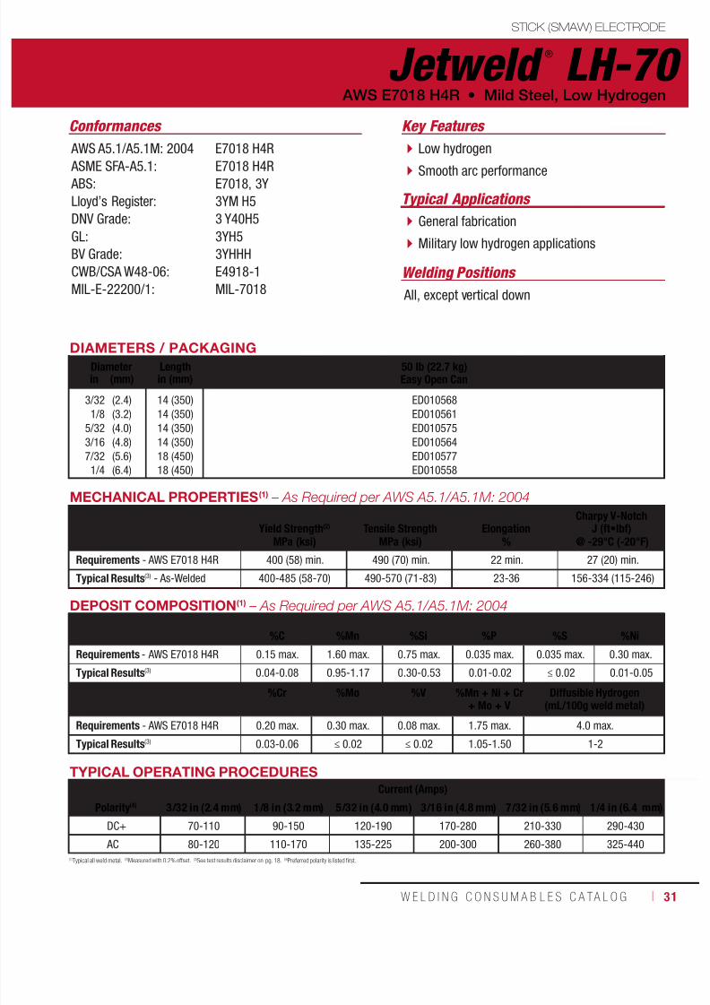
Jetweld ®
LH-70
Welding Positions
Typical Applications
All, except vertical down
General fabrication
Military low hydrogen applications
Low hydrogen
Smooth arc performance
Conformances
AWS E7018 H4R • Mild Steel, Low Hydrogen
Key Features
AWS A5.1/A5.1M: 2004
ASME SFA-A5.1: ABS:
Lloyd’s Register:
DNV Grade:
GL:
BV Grade:
CWB/CSA W48-06:
MIL-E-22200/1:
E7018 H4R
E7018 H4RE7018, 3Y
3YM H5
3 Y40H5
3YH5
3YHHH
E4918-1
MIL-7018
DIAMETERS / PACKAGING
Diameter Length 50 lb (22.7 kg)Easy Open Canin (mm) in (mm)
3/32
1/8
5/32
3/16
7/32
1/4
(2.4)
(3.2)
(4.0)
(4.8)
(5.6)
(6.4)
14 (350)
14 (350)
14 (350)
14 (350)
18 (450)
18 (450)
ED010568
ED010561
ED010575
ED010564
ED010577
ED010558
(1)Typical all weld metal. (2)Measured with 0.2% offset. (3)See test results disclaimer on pg. 18. (4)Preferred polarity is listed first.
TYPICAL OPERATING PROCEDURES
Current (Amps)
Polarity(4) 3/32 in (2.4 mm) 1/8 in (3.2 mm) 5/32 in (4.0 mm) 3/16 in (4.8 mm) 7/32 in (5.6 mm) 1/4 in (6.4 mm)
DC+ 70-110 90-150 120-190 170-280 210-330 290-430
AC 80-120 110-170 135-225 200-300 260-380 325-440
MECHANICAL PROPERTIES(1) – As Required per AWS A5.1/A5.1M: 2004
Yield Strength(2) Tensile Strength ElongationCharpy V-Notch
J (ft•lbf)MPa (ksi) MPa (ksi) % @ -29°C (-20°F)
Requirements - AWS E7018 H4R 400 (58) min. 490 (70) min. 22 min. 27 (20) min.
Typical Results(3) - As-Welded 400-485 (58-70) 490-570 (71-83) 23-36 156-334 (115-246)
DEPOSIT COMPOSITION(1) – As Required per AWS A5.1/A5.1M: 2004
%C %Mn %Si %P %S %Ni
Requirements - AWS E7018 H4R 0.15 max. 1.60 max. 0.75 max. 0.035 max. 0.035 max. 0.30 max.
Typical Results(3) 0.04-0.08 0.95-1.17 0.30-0.53 0.01-0.02 ≤ 0.02 0.01-0.05
%Cr %Mo %V %Mn + Ni + Cr+ Mo + V
Diffusible Hydrogen(mL/100g weld metal)
Requirements - AWS E7018 H4R 0.20 max. 0.30 max. 0.08 max. 1.75 max. 4.0 max.
Typical Results(3) 0.03-0.06 ≤ 0.02 ≤ 0.02 1.05-1.50 1-2

7/18/2019 c110 - Lincoln Electric Consumables 2014
http://slidepdf.com/reader/full/c110-lincoln-electric-consumables-2014 32/51132 ı T H E L I N C O L N E L E C T R I C C O M P A N Y
STICK (SMAW) ELECTRODE
Jet-LH ®
78 MR ®
Welding Positions
Typical Applications
All, except vertical down
General fabrication
Low hydrogen
Smooth arc performance
Conformances
Mild Steel, Low Hydrogen • AWS E7018 H4R
Key Features
AWS A5.1/A5.1M: 2004
ASME SFA-A5.1: ABS:
Lloyd’s Register:
DNV Grade:
GL:
BV Grade:
CWB/CSA W48-06
E7018 H4R
E7018 H4RE7018
3YM H5
3 YH5
3YH5
3YHHH
E4918-1
DIAMETERS / PACKAGING
Diameter Length 5 lb (2.3 kg) Plastic Tube20 lb (9.1 kg) Master Carton*
50 lb (22.7 kg)Easy Open Canin (mm) in (mm)
3/32
1/8
5/32
3/16
1/4
(2.4)
(3.2)
(4.0)
(4.8)
(6.4)
12 (300)
14 (350)
14 (350)
14 (350)
18 (450)
ED033517
ED033518
ED033519
ED015161
ED015198
ED015141
ED015186
ED015383
MECHANICAL PROPERTIES(1) – As Required per AWS A5.1/A5.1M: 2004
Yield Strength(2) Tensile Strength ElongationCharpy V-Notch
J (ft•lbf)MPa (ksi) MPa (ksi) % @ -29°C (-20°F)
Requirements - AWS E7018 H4R 400 (58) min. 490 (70) min. 22 min. 27 (20) min.
Typical Results(3) - As-Welded 415-570 (60-83) 495-640 (72-93) 22-34 156-353 (115-260)
TYPICAL OPERATING PROCEDURES
Current (Amps)
Polarity(4) 3/32 in (2.4 mm) 1/8 in (3.2 mm) 5/32 in (4.0 mm) 3/16 in (4.8 mm) 1/4 in (6.4 mm)
DC+ 65-100 110-160 130-200 180-270 300-400
AC 70-105 120-170 140-230 210-290 325-420
DEPOSIT COMPOSITION(1) – As Required per AWS A5.1/A5.1M: 2004
%C %Mn %Si %P %S %Ni
Requirements - AWS E7018 H4R 0.15 max. 1.60 max. 0.75 max. 0.035 max. 0.035 max. 0.30 max.
Typical Results(3) 0.04-0.07 0.75-1.35 0.13-0.69 ≤ 0.01 ≤ 0.01 0.02-0.04
%Cr %Mo %V%Mn + Ni + Cr
+ Mo + VDiffusible Hydrogen
(mL/100g weld metal)
Requirements - AWS E7018 H4R 0.20 max. 0.30 max. 0.08 max. 1.75 max. 4.0 max.
Typical Results(3) 0.02-0.06 ≤ 0.03 ≤ 0.03 1.00-1.40 1-3
(1)Typical all weld metal. (2)Measured with 0.2% offset. (3)See test results disclaimer on pg. 18. (4)Preferred polarity is listed first.
NOTE: Retail Small Packaging (RSP). All RSP products carry AWS compliance. Unlike the standard products, RSP products have no other agencies approvals.

7/18/2019 c110 - Lincoln Electric Consumables 2014
http://slidepdf.com/reader/full/c110-lincoln-electric-consumables-2014 33/511W E L D I N G C O N S U M A B L E S C A TA L O G ı 33
STICK (SMAW) ELECTRODE
(1)Typical all weld metal. (2)Measured with 0.2% offset. (3)See test results disclaimer on pg. 18. (4)Preferred polarity is listed first.
Lincoln ®
7018 AC
Welding Positions
Typical Applications All, except vertical down
General fabrication
Tack and skip welds
Thin sections
AC polarity welding
Low open circuit voltage operation Minimal spatter
Capable of cold re-strikes
Conformances
AWS E7018 H8 • Mild Steel, Low Hydrogen
Key Features
AWS A5.1/A5.1M: 2004
ASME SFA-A5.1:CWB/CSA W48-06:
E7018 H8
E7018 H8E4918-H8
DIAMETERS / PACKAGING
Diameter Length 1 lb (0.5 kg) Plastic Tube6 lb (2.7 kg) Master Carton
5 lb (2.3 kg) Plastic Tube20 lb (9.1 kg) Master Carton
50 lb (22.7 kg)Easy Open Canin (mm) in (mm)
3/32
1/8
5/32
(2.4)
(3.2)
(4.0)
14 (350)
14 (350)
14 (350)
ED033512
ED033513
ED033514
ED033515
ED033516
ED031732
ED031734
ED031738
TYPICAL OPERATING PROCEDURES
Current (Amps)
Polarity 3/32 in (2.4 mm) 1/8 in (3.2 mm) 5/32 in (4.0 mm)
AC 75-120 105-150 130-200
DC+ 70-115 100-140 120-185
MECHANICAL PROPERTIES(1) – As Required per AWS A5.1/A5.1M: 2004
Yield Strength(2)
Tensile Strength Elongation
Charpy V-Notch
J (ft•lbf)MPa (ksi) MPa (ksi) % @ -29°C (-20°F)
Requirements - AWS E7018 H8 400 (58) min. 490 (70) min. 22 min. 27 (20) min.
Typical Results(3) - As-Welded 435-625 (63-80) 515-685 (75-90) 23-29 27-76 (20-56)
DEPOSIT COMPOSITION(1) – As Required per AWS A5.1/A5.1M: 2004
%C %Mn %Si %P %S %Ni
Requirements - AWS E7018 H8 0.15 max. 1.60 max. 0.75 max. 0.035 max. 0.035 max. 0.30 max.
Typical Results(3) 0.04-0.07 1.00-1.60 0.32-0.63 0.01-0.02 ≤ 0.01 0.01-0.03
%Cr %Mo %V%Mn + Ni + Cr
+ Mo + VDiffusible Hydrogen
(mL/100g weld metal)
Requirements - AWS E7018 H8 0.20 max. 0.30 max. 0.08 max. 1.75 max. 8.0 max.
Typical Results(3) 0.03-0.08 ≤ 0.01 0.02-0.05 1.00-1.40 2-4
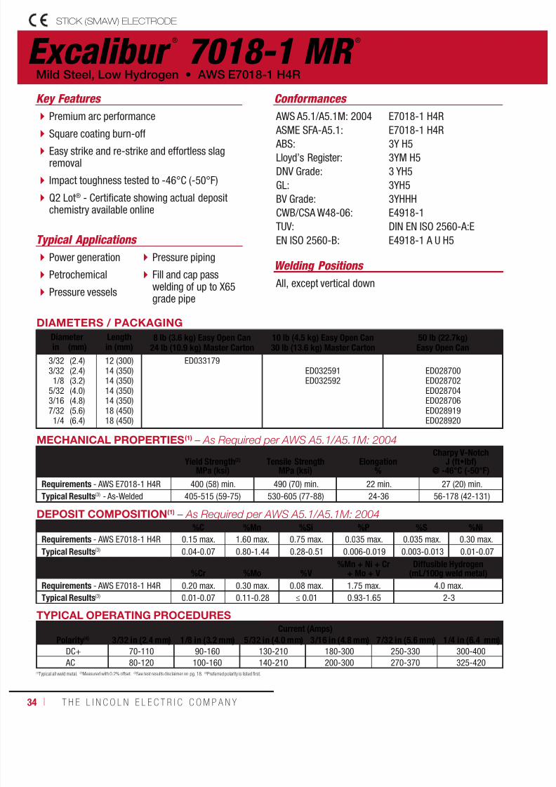
7/18/2019 c110 - Lincoln Electric Consumables 2014
http://slidepdf.com/reader/full/c110-lincoln-electric-consumables-2014 34/51134 ı T H E L I N C O L N E L E C T R I C C O M P A N Y
Excalibur ®
7018-1 MR ®
STICK (SMAW) ELECTRODE
Welding Positions
Typical Applications
All, except vertical down
Power generation
Petrochemical
Pressure vessels
Pressure piping
Fill and cap passwelding of up to X65grade pipe
Premium arc performance
Square coating burn-off Easy strike and re-strike and effortless slagremoval
Impact toughness tested to -46°C (-50°F)
Q2 Lot® - Certificate showing actual depositchemistry available online
Conformances
Mild Steel, Low Hydrogen • AWS E7018-1 H4R
Key Features
AWS A5.1/A5.1M: 2004
ASME SFA-A5.1: ABS:
Lloyd’s Register:
DNV Grade:
GL:
BV Grade:
CWB/CSA W48-06:
TUV:
EN ISO 2560-B:
E7018-1 H4R
E7018-1 H4R3Y H5
3YM H5
3 YH5
3YH5
3YHHH
E4918-1
DIN EN ISO 2560-A:E
E4918-1 A U H5
DIAMETERS / PACKAGING
Diameter Length 8 lb (3.6 kg) Easy Open Can24 lb (10.9 kg) Master Carton
10 lb (4.5 kg) Easy Open Can30 lb (13.6 kg) Master Carton
50 lb (22.7kg)Easy Open Canin (mm) in (mm)
3/323/321/8
5/32
3/167/321/4
(2.4)(2.4)(3.2)(4.0)
(4.8)(5.6)(6.4)
12 (300)14 (350)14 (350)14 (350)
14 (350)18 (450)18 (450)
ED033179ED032591ED032592
ED028700ED028702ED028704
ED028706ED028919ED028920
TYPICAL OPERATING PROCEDURES
Current (Amps)Polarity(4) 3/32 in (2.4 mm) 1/8 in (3.2 mm) 5/32 in (4.0 mm) 3/16 in (4.8 mm) 7/32 in (5.6 mm) 1/4 in (6.4 mm)
DC+ 70-110 90-160 130-210 180-300 250-330 300-400
AC 80-120 100-160 140-210 200-300 270-370 325-420
MECHANICAL PROPERTIES(1) – As Required per AWS A5.1/A5.1M: 2004
Yield Strength(2)
MPa (ksi)Tensile Strength
MPa (ksi)Elongation
%
Charpy V-NotchJ (ft•lbf)
@ -46°C (-50°F)
Requirements - AWS E7018-1 H4R 400 (58) min. 490 (70) min. 22 min. 27 (20) min.
Typical Results(3) - As-Welded 405-515 (59-75) 530-605 (77-88) 24-36 56-178 (42-131)
DEPOSIT COMPOSITION(1) – As Required per AWS A5.1/A5.1M: 2004%C %Mn %Si %P %S %Ni
Requirements - AWS E7018-1 H4R 0.15 max. 1.60 max. 0.75 max. 0.035 max. 0.035 max. 0.30 max.Typical Results(3) 0.04-0.07 0.80-1.44 0.28-0.51 0.006-0.019 0.003-0.013 0.01-0.07
%Cr %Mo %V%Mn + Ni + Cr
+ Mo + VDiffusible Hydrogen
(mL/100g weld metal)
Requirements - AWS E7018-1 H4R 0.20 max. 0.30 max. 0.08 max. 1.75 max. 4.0 max.
Typical Results(3) 0.01-0.07 0.11-0.28 ≤ 0.01 0.93-1.65 2-3
(1)Typical all weld metal. (2)Measured with 0.2% offset. (3)See test results disclaimer on pg. 18. (4)Preferred polarity is listed first.

7/18/2019 c110 - Lincoln Electric Consumables 2014
http://slidepdf.com/reader/full/c110-lincoln-electric-consumables-2014 35/511W E L D I N G C O N S U M A B L E S C A TA L O G ı 35
Excalibur ®
7028STICK (SMAW) ELECTRODE
Welding Positions
Typical Applications
Flat & Horizontal
Structural
Heavy fabrication Shipbuilding
Storage tanks
Bridge fabrication
High deposition rates
Premium arc performance High travel speed
H8 diffusible hydrogen levels
Capable of producing weld deposits withimpact toughness exceeding 84 J (60 ft•lbf)at -40°C (-40°F)
Conformances
AWS E7028 H8 • Mild Steel, Low Hydrogen
Key Features
AWS A5.1/A5.1M: 2004
ASME SFA-A5.1:
ABS:
Lloyd’s Register:
DNV Grade:
CWB/CSA W48-06:
E7028 H8
E7028 H8
E7028, 3Y H10 (Fillet Only)
3YM H10
3 YH10
E4928 H8
DIAMETERS / PACKAGING
Diameter Length 50 lb (22.7 kg)Easy Open Canin (mm) in (mm)
5/32
3/16
7/32
(4.0)
(4.8)
(5.6)
14 (350)
18 (450)
18 (450)
ED032636
ED032790
ED032638
(1)Typical all weld metal. (2)Measured with 0.2% offset. (3)See test results disclaimer on pg. 18. (4)Preferred polarity is listed first.
TYPICAL OPERATING PROCEDURES
Current (Amps)
Polarity(4) 5/32 in (4.0 mm) 3/16 in (4.8 mm) 7/32 in (5.6 mm)
AC 190-210 235-255 250-270
DC+ 160-180 215-235 260-280
MECHANICAL PROPERTIES(1)
Yield Strength(2) Tensile Strength ElongationCharpy V-Notch
J (ft•lbf)MPa (ksi) MPa (ksi) % @ -18°C (0°F)
Requirements - AWS E7028 H8 400 (58) min. 490 (70) min. 22 min. 27 (20) min.
Typical Results(3) - As-Welded 450-470 (66-69) 540-560 (77-85) 27-34 84-193 (62-142)
DEPOSIT COMPOSITION(1) – As Required per AWS A5.1/A5.1M: 2004
%C %Mn %Si %P %S %Ni
Requirements - AWS E7028 H8 0.15 max. 1.60 max. 0.90 max. 0.035 max. 0.035 max. 0.30 max.
Typical Results(3) 0.03-0.06 1.17-1.51 0.44-0.77 0.007-0.014 0.004-0.008 0.02-0.04
%Cr %Mo %V%Mn + Ni + Cr
+ Mo + VDiffusible Hydrogen
(mL/100g weld metal)
Requirements - AWS E7028 H8 0.20 max. 0.30 max. 0.08 max. 1.75 max. 8.0 max.
Typical Results(3) 0.02-0.05 0.01-0.03 0.02 max. 1.25-1.62 4-5

7/18/2019 c110 - Lincoln Electric Consumables 2014
http://slidepdf.com/reader/full/c110-lincoln-electric-consumables-2014 36/51136 ı T H E L I N C O L N E L E C T R I C C O M P A N Y
STICK (SMAW) ELECTRODE
Shield-Arc ®
HYP+
Welding Positions Typical Applications
AllRoot pass welding of up to X80 grade pipe
Hot, fill and cap pass of up to X65 grade pipe
Vertical down welding
Light slag for minimal arc interference
Deep penetration Clean, visible weld puddle
Superior puddle control
Conformances
Low Alloy, Cellulosic, Pipe • AWS E7010-P1
Key Features
AWS A5.5/A5.5M: 2006
ASME SFA-A5.5: ABS:
CWB/CSA W48-06:
TUV:
E7010-P1, E7010-G
E7010-P1, E7010-GE7010-P1
E4910-P1
DIN EN ISO 2560-A:E
DIAMETERS / PACKAGING
Diameter Length 50 lb (22.7 kg)Easy Open Canin (mm) in (mm)
1/8
5/32
3/16
(3.2)
(4.0)
(4.8)
14 (350)
14 (350)
14 (350)
ED029511
ED029513
ED029509
TYPICAL OPERATING PROCEDURES
Current (Amps)
Polarity 1/8 in (3.2 mm) 5/32 in (4.0 mm) 3/16 in (4.8 mm)
DC+ 75-130 90-185 140-225
MECHANICAL PROPERTIES(1) – As Required per AWS A5.5/A5.5M: 2006
Yield Strength(2) Tensile Strength ElongationCharpy V-Notch
J (ft•lbf)MPa (ksi) MPa (ksi) % @ -29°C (-20°F)
Requirements - AWS E7010-P1 415 (60) min. 490 (70) min. 22 min. 27 (20) min.
Typical Results(3) - As-Welded 435-525 (63-76) 525-635 (76-92) 22-28 27-56 (20-41)
DEPOSIT COMPOSITION(1) – As Required per AWS A5.5/A5.5M: 2006
%C %Mn %Si %P %S
Requirements - AWS E7010-P1 0.20 max. 1.20 max. 0.60 max. 0.03 max. 0.03 max.
Typical Results(3) 0.13-0.17 0.43-0.63 0.08-0.18 ≤ 0.01 ≤ 0.01
%Ni %Cr %Mo %V
Requirements - AWS E7010-P1 1.00 max. 0.30 max. 0.50 max. 0.10 max.
Typical Results(3) 0.01-0.02 0.02 0.27-0.31 < 0.01
(1)Typical all weld metal. (2)Measured with 0.2% offset. (3)See test results disclaimer on pg. 18.

7/18/2019 c110 - Lincoln Electric Consumables 2014
http://slidepdf.com/reader/full/c110-lincoln-electric-consumables-2014 37/511W E L D I N G C O N S U M A B L E S C A TA L O G ı 37
STICK (SMAW) ELECTRODE
Shield-Arc ®
85
Welding Positions Typical Applications
All API 5L X42 through X56 grade pipe
Cross country and in-plant pipe
For welding 0.50% molybdenum steel
Light slag for minimal arc interference Deep penetration and superior puddle control
Clean, visible weld puddle
Capable of 480 MPa (70 ksi) tensile strengthweld deposits
Conformances
AWS E7010-A1 • Low Alloy, Cellulosic, Pipe
Key Features
AWS A5.5/A5.5M: 2006
ASME SFA-A5.5: ABS:
CWB/CSA W48-06:
TUV:
MIL-E-22200/7:
E7010-A1
E7010-A1E7010-A1
E4910-A1
DIN EN ISO 2560-A:E
MIL-7010-A1
DIAMETERS / PACKAGING
Diameter Length 50 lb (22.7 kg)Easy Open Canin (mm) in (mm)
3/32
1/8
5/32
3/16
(2.4)
(3.2)
(4.0)
(4.8)
12 (300)
14 (350)
14 (350)
14 (350)
ED012893
ED012885
ED012896
ED012889
DEPOSIT COMPOSITION
(1)
– As Required per AWS A5.5/A5.5M: 2006%C %Mn %Si %P %S %Mo
Requirements - AWS E7010-A1 0.12 max. 0.60 max 0.40 max 0.03 max 0.03 max 0.40-0.65
Typical Results(3) 0.07-0.12 0.29-0.59 0.08-0.26 0.01-0.02 ≤ 0.01 0.40-0.62
TYPICAL OPERATING PROCEDURES
Current (Amps)
Polarity 3/32 in (2.4 mm) 1/8 in (3.2 mm) 5/32 in (4.0 mm) 3/16 in (4.8 mm)
DC+ 50-90 75-130 90-175 140-225
(1)Typical all weld metal. (2)Measured with 0.2% offset. (3)See test results disclaimer on pg. 18.
MECHANICAL PROPERTIES(1) – As Required per AWS A5.5/A5.5M: 2006
Yield Strength(2) Tensile Strength ElongationCharpy V-Notch
J (ft•lbf)MPa (ksi) MPa (ksi) % @ -29°C (-20°F)
Requirements - AWS E7010-A1 390 (57) min. 490 (70) min. 22 min. Not Specified
Typical Results(3) - As-Welded 440-510 (64-74) 540-580 (78-84) 25-30 35-43 (26-32)

7/18/2019 c110 - Lincoln Electric Consumables 2014
http://slidepdf.com/reader/full/c110-lincoln-electric-consumables-2014 38/51138 ı T H E L I N C O L N E L E C T R I C C O M P A N Y
STICK (SMAW) ELECTRODE
Shield-Arc ®
70+
Welding Positions Typical Applications
AllRelatively high silicon pipe
API 5L X56 through X70 grade pipe
Cross country and in-plant pipe
Light slag for minimal arc interference
Deep penetration Clean, visible weld puddle
Superior puddle control
Conformances
AWS E8010-G • Low Alloy, Cellulosic, Pipe
Key Features
AWS A5.5/A5.5M: 2006
ASME SFA-A5.5: ABS:
CWB/CSA W48-06:
TUV:
E8010-G, E8010-P1*
E8010-G, E8010-P1*E8010-G
E5510-G
DIN EN ISO 2560-A:E
DIAMETERS / PACKAGING
Diameter Length 50 lb (22.7 kg)Easy Open Canin (mm) in (mm)
1/8
5/32
3/16
(3.2)
(4.0)
(4.8)
14 (350)
14 (350)
14 (350)
ED012841
ED012849
ED012845
* This product is classified as an E8010-G; however, it also meets the requirements of an E8010-P1.
TYPICAL OPERATING PROCEDURES
Current (Amps)
Polarity 1/8 in (3.2 mm) 5/32 in (4.0 mm) 3/16 in (4.8 mm)
DC+ 75-130 90-185 140-225
MECHANICAL PROPERTIES(1) – As Required per AWS A5.5/A5.5M: 2006
Yield Strength(2) Tensile Strength Elongation Charpy V-NotchJ (ft•lbf)MPa (ksi) MPa (ksi) % @ -29°C (-20°F) @ -46°C (-50°F)
Requirements - AWS E8010-G 460 (67) min. 550 (80) min. 19 min. Not Specified Not Specified
Typical Results(3) - As-Welded 460-620 (67-90) 585-690 (85-100) 19-31 37-81 (27-60) 26-64 (19-47)
DEPOSIT COMPOSITION(1)
%C %Mn %Si %P %S
Requirements(4) - AWS E8010-G Not Specified 1.00 min. 0.80 min. 0.03 max. 0.03 max.
Typical Results
(3)
0.13-0.17 0.60-1.20 0.05-0.30 ≤ 0.01 ≤ 0.01%Ni %Cr %Mo %V
Requirements(4) - AWS E8010-G 0.50 min. 0.30 min. 0.20 min. 0.10 min.
Typical Results(3) 0.75-0.97 0.01-0.20 0.35-0.45 0.02-0.04
(1)Typical all weld metal. (2)Measured with 0.2% offset. (3)See test results disclaimer on pg. 18. (4)In order to meet the alloy requirements of the “G” designation, the undiluted weld metal shall have the minimum of at least one of the elements listed.

7/18/2019 c110 - Lincoln Electric Consumables 2014
http://slidepdf.com/reader/full/c110-lincoln-electric-consumables-2014 39/511W E L D I N G C O N S U M A B L E S C A TA L O G ı 39
STICK (SMAW) ELECTRODE
Shield-Arc ®
90
Welding Positions
Typical Applications
All
Hot pass welding of up to X80 grade pipe,when followed by low hydrogen fill and cap
API 5L X70 through X80 grade pipe
Cross country pipe
Light slag for minimal arc interference
Deep penetrationClean, visible weld puddle
Superior puddle control
Conformances
AWS E9010-G • Low Alloy, Cellulosic, Pipe
Key Features
AWS A5.5/A5.5M: 2006
ASME SFA-A5.5:
E9010-G
E9010-G
DIAMETERS / PACKAGING
Diameter Length 50 lb (22.7 kg)Easy Open Canmm (in) in (mm)
3.2
4.0
5.0
(1/8)
(5/32)
(3/16)
14 (350)
14 (350)
14 (350)
EDS01693
EDS01694
EDS01695
TYPICAL OPERATING PROCEDURES
Current (Amps)
Polarity 3.2 mm (1/8 in) 4.0 mm (5/32 in) 4.8 mm (3/16 in)
DC+ 75-130 80-185 140-225
MECHANICAL PROPERTIES(1)
– As Required per AWS A5.5/A5.5M: 2006
Yield Strength(2) Tensile Strength ElongationCharpy V-Notch
J (ft•lbf)MPa (ksi) MPa (ksi) % @ -29°C (-20°F) @ -46°C (-50°F)
Requirements - AWS E9010-G 530 (77) min. 620 (90) min. 17 min. Not Specified Not Specified
Typical Results(3) - As-Welded 530-605 (77-88) 620-690 (90-100) 17-29 45-94 (33-69) 28-62 (21-46)
DEPOSIT COMPOSITION(1) – As Required per AWS A5.5/A5.5M: 2006
%C %Mn %Si %P %S
Requirements(4) - AWS E9010-G Not Specified 1.00 min. 0.80 min. 0.03 max. 0.03 max.
Typical Results(3) 0.13-0.18 0.55-0.79 0.08-0.22 0.01-0.02 ≤ 0.01
%Ni %Cr %Mo %V
Requirements - AWS E9010-G 0.50 min. 0.30 min. 0.20 min. 0.10 min.
Typical Results(3) 0.66-0.77 0.01-0.06 0.43-0.70 ≤ 0.01
(1)Typical all weld metal. (2)Measured with 0.2% offset. (3)See test results disclaimer on pg. 18. (4)In order to meet the alloy requirements of the “G” designation, the undiluted weld metal shall have the minimum of at least one of the elements listed.
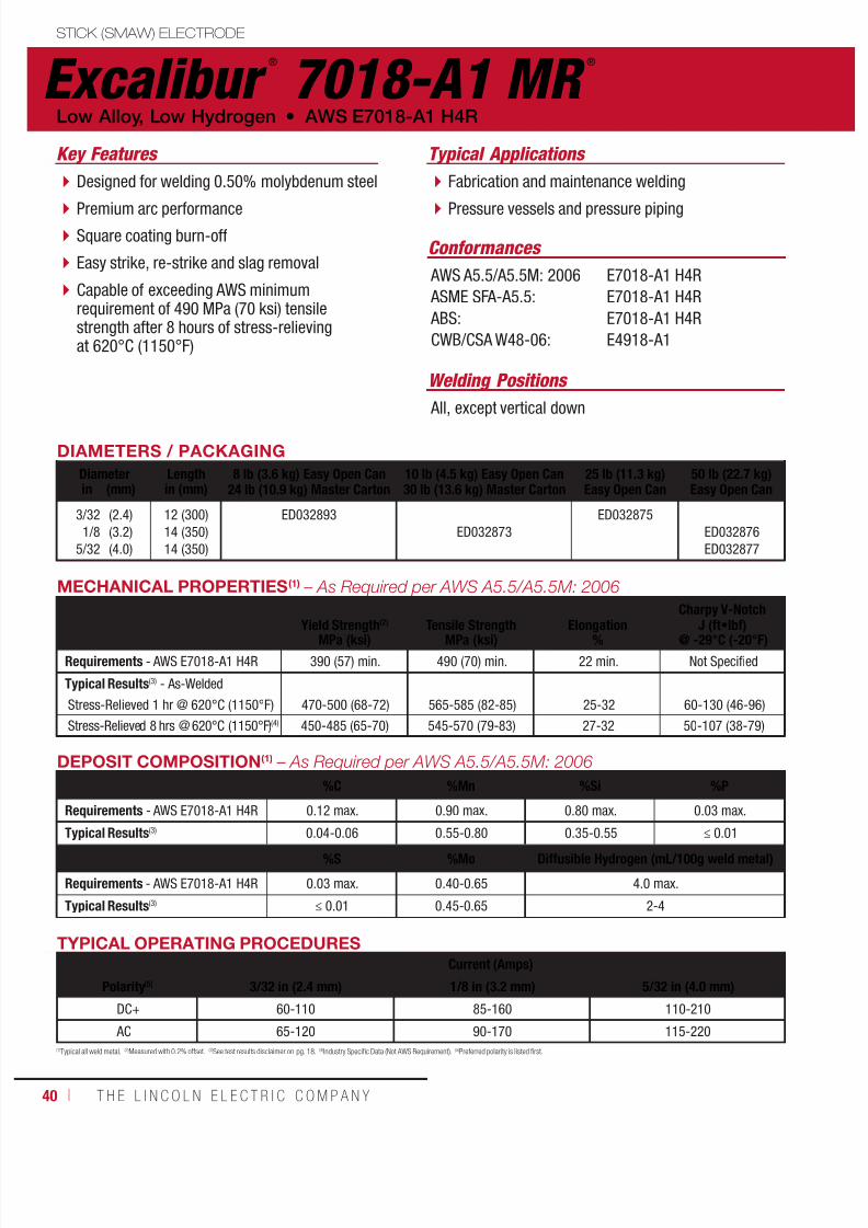
7/18/2019 c110 - Lincoln Electric Consumables 2014
http://slidepdf.com/reader/full/c110-lincoln-electric-consumables-2014 40/51140 ı T H E L I N C O L N E L E C T R I C C O M P A N Y
STICK (SMAW) ELECTRODE
Excalibur ®
7018-A1 MR ®
Welding Positions
Typical Applications
All, except vertical down
Fabrication and maintenance welding
Pressure vessels and pressure piping
Designed for welding 0.50% molybdenum steel
Premium arc performance Square coating burn-off
Easy strike, re-strike and slag removal
Capable of exceeding AWS minimumrequirement of 490 MPa (70 ksi) tensilestrength after 8 hours of stress-relievingat 620°C (1150°F)
Conformances
Low Alloy, Low Hydrogen • AWS E7018-A1 H4R
Key Features
AWS A5.5/A5.5M: 2006
ASME SFA-A5.5:
ABS:
CWB/CSA W48-06:
E7018-A1 H4R
E7018-A1 H4R
E7018-A1 H4R
E4918-A1
DIAMETERS / PACKAGING
Diameter Length 8 lb (3.6 kg) Easy Open Can24 lb (10.9 kg) Master Carton
10 lb (4.5 kg) Easy Open Can30 lb (13.6 kg) Master Carton
25 lb (11.3 kg)Easy Open Can
50 lb (22.7 kg)Easy Open Canin (mm) in (mm)
3/32
1/8
5/32
(2.4)
(3.2)
(4.0)
12 (300)
14 (350)
14 (350)
ED032893
ED032873
ED032875
ED032876
ED032877
DEPOSIT COMPOSITION(1) – As Required per AWS A5.5/A5.5M: 2006
%C %Mn %Si %P
Requirements - AWS E7018-A1 H4R 0.12 max. 0.90 max. 0.80 max. 0.03 max.
Typical Results
(3)
0.04-0.06 0.55-0.80 0.35-0.55 ≤ 0.01%S %Mo Diffusible Hydrogen (mL/100g weld metal)
Requirements - AWS E7018-A1 H4R 0.03 max. 0.40-0.65 4.0 max.
Typical Results(3) ≤ 0.01 0.45-0.65 2-4
TYPICAL OPERATING PROCEDURES
Current (Amps)
Polarity(5) 3/32 in (2.4 mm) 1/8 in (3.2 mm) 5/32 in (4.0 mm)
DC+ 60-110 85-160 110-210
AC 65-120 90-170 115-220
(1)Typical all weld metal. (2)Measured with 0.2% offset. (3)See test results disclaimer on pg. 18. (4)Industry Specific Data (Not AWS Requirement). (5)Preferred polarity is listed first.
MECHANICAL PROPERTIES(1) – As Required per AWS A5.5/A5.5M: 2006
Yield Strength(2)
Tensile Strength Elongation
Charpy V-Notch
J (ft•lbf)MPa (ksi) MPa (ksi) % @ -29°C (-20°F)
Requirements - AWS E7018-A1 H4R 390 (57) min. 490 (70) min. 22 min. Not Specified
Typical Results(3) - As-Welded
Stress-Relieved 1 hr @ 620°C (1150°F) 470-500 (68-72) 565-585 (82-85) 25-32 60-130 (46-96)
Stress-Relieved 8 hrs @ 620°C (1150°F)(4) 450-485 (65-70) 545-570 (79-83) 27-32 50-107 (38-79)
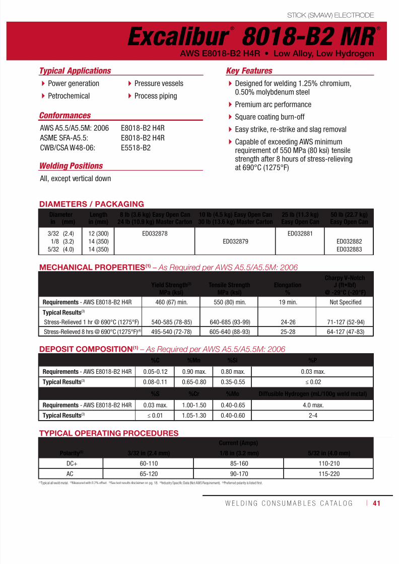
7/18/2019 c110 - Lincoln Electric Consumables 2014
http://slidepdf.com/reader/full/c110-lincoln-electric-consumables-2014 41/511W E L D I N G C O N S U M A B L E S C A TA L O G ı 41
STICK (SMAW) ELECTRODE
Excalibur ®
8018-B2 MR ®
Welding Positions
Typical Applications
All, except vertical down
Power generation
Petrochemical
Pressure vessels
Process piping
Designed for welding 1.25% chromium,0.50% molybdenum steel
Premium arc performance
Square coating burn-off
Easy strike, re-strike and slag removal
Capable of exceeding AWS minimumrequirement of 550 MPa (80 ksi) tensilestrength after 8 hours of stress-relievingat 690°C (1275°F)
Conformances
AWS E8018-B2 H4R • Low Alloy, Low Hydrogen
Key Features
AWS A5.5/A5.5M: 2006
ASME SFA-A5.5:
CWB/CSA W48-06:
E8018-B2 H4R
E8018-B2 H4R
E5518-B2
DIAMETERS / PACKAGING
Diameter Length 8 lb (3.6 kg) Easy Open Can24 lb (10.9 kg) Master Carton
10 lb (4.5 kg) Easy Open Can30 lb (13.6 kg) Master Carton
25 lb (11.3 kg)Easy Open Can
50 lb (22.7 kg)Easy Open Canin (mm) in (mm)
3/32
1/8
5/32
(2.4)
(3.2)
(4.0)
12 (300)
14 (350)
14 (350)
ED032878
ED032879
ED032881
ED032882
ED032883
TYPICAL OPERATING PROCEDURES
Current (Amps)
Polarity(5) 3/32 in (2.4 mm) 1/8 in (3.2 mm) 5/32 in (4.0 mm)
DC+ 60-110 85-160 110-210
AC 65-120 90-170 115-220
(1)Typical all weld metal. (2)Measured with 0.2% offset. (3)See test results disclaimer on pg. 18. (4)Industry Specific Data (Not AWS Requirement). (5)Preferred polarity is listed first.
MECHANICAL PROPERTIES(1) – As Required per AWS A5.5/A5.5M: 2006
Yield Strength(2) Tensile Strength ElongationCharpy V-Notch
J (ft•lbf)MPa (ksi) MPa (ksi) % @ -29°C (-20°F)
Requirements - AWS E8018-B2 H4R 460 (67) min. 550 (80) min. 19 min. Not Specified
Typical Results(3)
Stress-Relieved 1 hr @ 690°C (1275°F) 540-585 (78-85) 640-685 (93-99) 24-26 71-127 (52-94)
Stress-Relieved 8 hrs @ 690°C (1275°F)(4) 495-540 (72-78) 605-640 (88-93) 25-28 64-127 (47-83)
DEPOSIT COMPOSITION(1) – As Required per AWS A5.5/A5.5M: 2006
%C %Mn %Si %P
Requirements - AWS E8018-B2 H4R 0.05-0.12 0.90 max. 0.80 max. 0.03 max.
Typical Results(3) 0.08-0.11 0.65-0.80 0.35-0.55 ≤ 0.02
%S %Cr %Mo Diffusible Hydrogen (mL/100g weld metal)
Requirements - AWS E8018-B2 H4R 0.03 max. 1.00-1.50 0.40-0.65 4.0 max.
Typical Results(3) ≤ 0.01 1.05-1.30 0.40-0.60 2-4

7/18/2019 c110 - Lincoln Electric Consumables 2014
http://slidepdf.com/reader/full/c110-lincoln-electric-consumables-2014 42/51142 ı T H E L I N C O L N E L E C T R I C C O M P A N Y
STICK (SMAW) ELECTRODE
Excalibur ®
8018-C1 MR ®
Welding Positions
Typical Applications
All, except vertical down
Low temperatureapplications
Refrigerated ammoniatanks
Liquefied gas storage,piping and transportation
Weathering steels
Designed to produce a nominal 2.25%nickel deposit
Premium arc performance
Square coating burn-off
Easy strike, re-strike and slag removal
Capable of exceeding AWS minimumrequirement of 550 MPa (80 ksi) tensilestrength after 1 hour of stress-relievingat 610°C (1125°F)
Conformances
Low Alloy, Low Hydrogen • AWS E8018-C1 H4R
Key Features
AWS A5.5/A5.5M: 2006
ASME SFA-A5.5:
CWB/CSA W48-06:
E8018-C1 H4R
E8018-C1 H4R
E5518-C1
DIAMETERS / PACKAGING
Diameter Length 50 lb (22.7 kg)Easy Open Canin (mm) in (mm)
3/32
1/8
5/32
3/16
1/4
(2.4)
(3.2)
(4.0)
(4.8)
(6.4)
14 (350)
14 (350)
14 (350)
14 (350)
18 (450)
ED030876
ED030877
ED030878
ED030879
ED030880
DEPOSIT COMPOSITION(1) – As Required per AWS A5.5/A5.5M: 2006
%C %Mn %Si %P
Requirements - AWS E8018-C1 H4R 0.12 max. 1.25 max. 0.80 max. 0.03 max.
Typical Results(3) - As-Welded 0.05-0.09 0.89-1.25 0.17-0.53 ≤ 0.02
%S %Ni Diffusible Hydrogen (mL/100g weld deposit)
Requirements - AWS E8018-C1 H4R 0.03 max. 2.00-2.75 4.0 max.
Typical Results(3) - As-Welded ≤ 0.01 2.00-2.58 1-3
TYPICAL OPERATING PROCEDURES
Current (Amps)
Polarity(5) 3/32 in (2.4 mm) 1/8 in (3.2 mm) 5/32 in (4.0 mm) 3/16 in (4.8 mm) 7/32 in (5.6 mm) 1/4 in(6.4 mm)
DC+ 70-110 90-160 130-210 180-300 250-330 300-400
AC 80-120 100-160 140-210 200-300 270-370 325-430
MECHANICAL PROPERTIES(1)
Yield Strength(2) Tensile Strength ElongationCharpy V-Notch
J (ft•lbf)MPa (ksi) MPa (ksi) % @ -59°C (-75°F)
Requirements - AWS E8018-C1 H4R 460 (67) min. 550 (80) min. 19 min. 20 (27) min.
Typical Results(3)
Stress-Relieved 1 hr @ 610°C (1125°F)(4) 460-525 (67-76) 565-615 (82-89) 24-32 79-129 (58-95)
(1)Typical all weld metal. (2)Measured with 0.2% offset. (3)See test results disclaimer on pg. 18. (4)Industry Specific Data (Not AWS Requirement). (5)Preferred polarity is listed first.

7/18/2019 c110 - Lincoln Electric Consumables 2014
http://slidepdf.com/reader/full/c110-lincoln-electric-consumables-2014 43/511W E L D I N G C O N S U M A B L E S C A TA L O G ı 43
STICK (SMAW) ELECTRODE
Excalibur ®
8018-C3 MR ®
Welding Positions
Typical Applications
All, except vertical down
Shipbuilding
Piping and gasstorage tanks
Weathering steels
Cross countrypipe repair
Designed to produce a 1% nickel deposit
Premium arc performanceSquare coating burn-off
Easy strike and re-strike
Effortless slag removalConformances
AWS E8018-C3 H4R • Low Alloy, Low Hydrogen
Key Features
AWS A5.5/A5.5M: 2006
ASME SFA-A5.5:
ABS:
CWB/CSA W48-06:
EN ISO 2560-B:
E8018-C3 H4R
E8018-C3 H4R
E8018-C3 H4R
E5518-C3
E5518-N2 A U H5
DIAMETERS / PACKAGING
Diameter Length 10 lb (4.5 kg) Easy Open Can30 lb (13.6 kg) Master Carton
50 lb (22.7 kg)Easy Open Canin (mm) in (mm)
3/32
1/8
5/32
3/16
7/32
1/4
(2.4)
(3.2)
(4.0)
(4.8)
(5.6)
(6.4)
14 (350)
14 (350)
14 (350)
14 (350)
18 (450)
18 (450)
ED032599
ED032600
ED030892
ED030893
ED030894
ED030895
ED030897
ED030896
TYPICAL OPERATING PROCEDURES
Current (Amps)
Polarity(4) 3/32 in (2.4 mm) 1/8 in (3.2 mm) 5/32 in (4.0 mm) 3/16 in (4.8 mm) 7/32 in (5.6 mm) 1/4 in (6.4 mm)
DC± 70-110 90-160 130-210 180-300 250-330 300-400
AC 80-120 100-160 140-210 200-300 270-370 325-425
MECHANICAL PROPERTIES(1) – As Required per AWS A5.5/A5.5M: 2006
Yield Strength(2) Tensile Strength ElongationCharpy V-Notch
J (ft•lbf)MPa (ksi) MPa (ksi) % @ -40°C (-40°F)
Requirements - AWS E8018-C3 H4R 470-550 (68-80) 550 (80) min. 24 min. 27 (20) min.
Typical Results(3) - As-Welded 505-590 (73-86) 550-675 (80-98) 24-32 81-163 (60-120)
(1)Typical all weld metal. (2)Measured with 0.2% offset. (3)See test results disclaimer on pg. 18. (4)Preferred polarity is listed first.
DEPOSIT COMPOSITION(1) – As Required per AWS A5.5/A5.5M: 2006
%C %Mn %Si %P %S
Requirements - AWS E8018-C3 H4R 0.12 max. 0.40-1.25 0.80 max. 0.03 max. 0.03 max.
Typical Results(3) 0.04-0.07 0.40-1.25 0.23-0.46 ≤ 0.01 ≤ 0.009
%Ni %Cr %Mo %VDiffusible Hydrogen
(mL/100g weld deposit)
Requirements - AWS E8018-C3 H4R 0.80-1.10 0.15 max. 0.35 max. 0.05 max. 4.0 max.
Typical Results(3) 0.81-1.09 0.04-0.06 0.07-0.27 ≤ 0.01 1-2

7/18/2019 c110 - Lincoln Electric Consumables 2014
http://slidepdf.com/reader/full/c110-lincoln-electric-consumables-2014 44/51144 ı T H E L I N C O L N E L E C T R I C C O M P A N Y
STICK (SMAW) ELECTRODE
Excalibur ®
9018-B3 MR ®
Welding Positions
Typical Applications
All, except vertical down
2.25% chromium,1% molybdenum steels
Power generation
Petrochemical
Pressure vessels Process piping
Designed for all-position welding of 2.25%chromium, 1% molybdenum low alloy steels
Premium arc performance
Square coating burn-off
Easy strike, re-strike and slag removal
Capable of exceeding AWS minimumrequirements of 620 MPa (90 ksi) tensilestrength after 8 hours of stress-relievingat 690°C (1275°F)
Conformances
Low Alloy, Low Hydrogen • AWS E9018-B3 H4R
Key Features
AWS A5.5/A5.5M: 2006
ASME SFA-A5.5:
CWB/CSA W48-06:
E9018-B3 H4R
E9018-B3 H4R
E6218-B3
DIAMETERS / PACKAGING
Diameter Length 8 lb (3.6 kg) Easy Open Can24 lb (10.9 kg) Master Carton
10 lb (4.5 kg) Easy Open Can30 lb (13.6 kg) Master Carton
25 lb (11.3 kg)Easy Open Can
50 lb (22.7 kg)Easy Open Canin (mm) in (mm)
3/32
1/8
5/32
(2.4)
(3.2)
(4.0)
12 (300)
14 (350)
14 (350)
ED032884
ED032885
ED032887
ED032888
ED032889
TYPICAL OPERATING PROCEDURES
Current (Amps)
Polarity(5) 3/32 in (2.4 mm) 1/8 in (3.2 mm) 5/32 in (4.0 mm)
DC+ 60-110 85-160 110-210
AC 65-120 90-170 115-220
(1)Typical all weld metal. (2)Measured with 0.2% offset. (3)See test results disclaimer on pg. 18. (4)Industry Specific Data (Not AWS Requirement). (5)Preferred polarity is listed first.
MECHANICAL PROPERTIES(1) – As Required per AWS A5.5/A5.5M: 2006
Yield Strength
(2)
Tensile Strength Elongation
Charpy V-Notch
J (ft•lbf)MPa (ksi) MPa (ksi) % @ -40°C (-40°F)
Requirements - AWS E9018-B3 H4R 530 (77) min. 620 (90) min. 17 min. Not Specified
Typical Results(3)
Stress-Relieved 1 hr @ 690°C (1275°F) 595-605 (86-88) 705-715 (102-104) 20-23 57-72 (42-53)
Stress-Relieved 8 hrs @ 690°C (1275°F)(4) 530-580 (77-84) 650-685 (94-99) 20-24 43-107 (32-79)
DEPOSIT COMPOSITION(1) – As Required per AWS A5.5/A5.5M: 2006
%C %Mn %Si %P
Requirements - AWS E9018-B3 H4R 0.05-0.12 0.90 max. 0.80 max. 0.03 max.
Typical Results(3) 0.07-0.1 0.65-0.79 0.39-0.49 ≤0.01
%S %Cr %Mo Diffusible Hydrogen (mL/100g weld metal)
Requirements - AWS E9018-B3 H4R 0.03 max. 2.00-2.50 0.90-1.20 4.0 max.
Typical Results(3) ≤0.01 2.21-2.46 1.03-1.13 2-4

7/18/2019 c110 - Lincoln Electric Consumables 2014
http://slidepdf.com/reader/full/c110-lincoln-electric-consumables-2014 45/511W E L D I N G C O N S U M A B L E S C A TA L O G ı 45
DIAMETERS / PACKAGINGDiameter Length 10 lb (4.5 kg) Easy Open Can
30 lb (13.6 kg) Master Carton50 lb (22.7 kg)Easy Open Canin (mm) in (mm)
3/321/8
5/323/16
(2.4)(3.2)(4.0)(4.8)
14 (350)14 (350)14 (350)14 (350)
ED032602ED032603
ED030868ED030869ED030870ED030871
TYPICAL OPERATING PROCEDURES
Current (Amps)
Polarity 3/32 in (2.4 mm) 1/8 in(3.2 mm) 5/32 in (4.0 mm) 3/16 in (4.8 mm)
DC+ 70-110 90-160 130-210 180-300
(1)Typical all weld metal. (2)Measured with 0.2% offset. (3)See test results disclaimer on pg. 18.
MECHANICAL PROPERTIES(1) – As Required per AWS A5.5/A5.5M: 2006
Yield Strength(2)
MPa (ksi)Tensile Strength
MPa (ksi)Elongation
%
Charpy V-NotchJ (ft•lbf)
@ -50°C (-60°F)
Requirements - AWS E9018M H4R 540-620 (78-90) min. 620 (90) min. 24 min. 27 (20) min.
Typical Results(3) - As-Welded 540-620 (78-90) 620-705 (90-102) 24-37 27-122 (20-90)
DEPOSIT COMPOSITION(1) – As Required per AWS A5.5/A5.5M: 2006%C %Mn %Si %P %S
Requirements - AWS E9018M H4R 0.10 max. 0.60-1.25 0.80 max. 0.03 max. 0.03 max.
Typical Results(3) 0.04-0.07 0.90-1.10 0.30-0.50 0.01-0.02 ≤ 0.01
%Ni %Cr %MoDiffusible Hydrogen
(mL/100g weld deposit)
Requirements - AWS E9018M H4R 1.40-1.80 0.15 max. 0.35 max. 4.0 max.
Typical Results(3) 1.50-1.80 0.05-0.12 0.25-0.35 1-3
STICK (SMAW) ELECTRODE
Excalibur ®
9018M MR ®
Welding Positions
Typical Applications
All, except vertical down
High strength steel, such as HY-80, HY-90 and ASTM A514
Cross country pipe repair
DC welding
Designed to produce weld deposits with620 MPa (90 ksi) tensile strength
Premium arc performance
Square coating burn-off
Easy strike and re-strike
Effortless slag removalConformances
AWS E9018M H4R • Low Alloy, Low Hydrogen
Key Features
AWS A5.5/A5.5M: 2006 ASME SFA-A5.5: ABS:CWB/CSA W48-06:
E9018M H4RE9018M H4RE9018M H4RE6218-M H4R (9018M H4R)

7/18/2019 c110 - Lincoln Electric Consumables 2014
http://slidepdf.com/reader/full/c110-lincoln-electric-consumables-2014 46/51146 ı T H E L I N C O L N E L E C T R I C C O M P A N Y
DIAMETERS / PACKAGINGDiameter Length 25 lb (11.3 kg)
Easy Open Can50 lb (22.7 kg)Easy Open Canin (mm) in (mm)
3/321/8
5/32
(2.4)(3.2)(4.0)
12 (300)14 (350)14 (350)
ED033162ED033163ED033164
(1)Typical all weld metal. (2)Measured with 0.2% offset. (3)See test results disclaimer on pg. 18. (4)Industry specific data, not required by AWS. (5)Preferred polarity is listed first.NOTE: Additional test data available upon r equest.
DEPOSIT COMPOSITION(1)
%C %Mn %Si %P
Requirements - AWS E10018-D2 H4R 0.15 max. 1.65-2.00 0.80 max. 0.03 max.Typical Results(3) 0.08-0.12 1.69-1.91 0.35-0.49 0.01-0.02
%S %Ni %MoDiffusible Hydrogen
(mL/100g weld deposit)Requirements - AWS E10018-D2 H4R 0.03 max. 0.90 max. 0.25-0.45 4.0 max.
Typical Results(3) ≤0.01 0.68-0.77 0.34-0.39 2-3
TYPICAL OPERATING PROCEDURESCurrent (Amps)
Polarity 3/32 in (2.4 mm) 1/8 in (3.2 mm) 5/32 in (4.0 mm)DC+ 60-110 85-160 110-210
AC 65-120 90-170 115-220
MECHANICAL PROPERTIES(1) – As Required per AWS A5.5/A5.5M: 2006
Yield Strength(2)
MPa (ksi)Tensile Strength
MPa (ksi)Elongation
%
Charpy V-NotchJ (ft•lbf)
@ -51°C (-60°F)Hardness(4)
HV10
Requirements - AWS E10018-D2 H4R 600 (87) min. 690 (100) min. 16 min. 27 (20) min. Not Specified
Typical Results(3) - Stress-Relieved 1 hr @ 620°C (1150°F) 650-715 (94-104) 725-780 (105-113) 22-25 56-69 (41-51) 219-242
Welded on AISI 4130 Steel
Typical Results(3) - Stress-Relieved 12 hrs @ 620°C (1150°F)(4) 560-580 (81-84) 650-675 (94-98) 24-25 47-68 (35-50) 210-214
STICK (SMAW) ELECTRODE
Excalibur ®
10018-D2 MR ®
Welding Positions
Typical Applications
All, except vertical down
Chromium-molybdenum and other low alloy steels,including AISI 4130, 4140, 8630 and ASTM A182 and A336 Grades F22
Carbon-manganese and other low alloy steels
Offshore and subsea components
Process piping
Meets NACE MR0175/ISO15156-2
Capable of exceeding 550 MPa (80 ksi) yieldstrength after 12 hours at 635°C (1175°F) on4130 AISI steel
Premium arc performance
Q2 Lot® - Certificate showing actual depositchemistry available online
Easy strike and re-strike
Effortless slag removalConformances
Low Alloy, Low Hydrogen • AWS E10018-D2 H4R
Key Features
AWS A5.5/A5.5M: 2006 ASME SFA-A5.5: ABS:
Lloyd’s Register:DNV Grade:CWB/CSA W48-06:
E10018-D2 H4RE10018-D2 H4R3YQ620 H5
3Y62 H53Y62 H5E6918-D2

7/18/2019 c110 - Lincoln Electric Consumables 2014
http://slidepdf.com/reader/full/c110-lincoln-electric-consumables-2014 47/511W E L D I N G C O N S U M A B L E S C A TA L O G ı 47
STICK (SMAW) ELECTRODE
TYPICAL OPERATING PROCEDURES
Current (Amps)
Polarity 3/32 in (2.4 mm) 1/8 in (3.2 mm) 5/32 in (4.0 mm) 3/16 in (4.8 mm)
DC+ 70-110 90-160 130-210 180-300
(1)Typical all weld metal. (2)Measured with 0.2% offset. (3)See test results disclaimer on pg. 18.
MECHANICAL PROPERTIES(1) – As Required per AWS A5.5/A5.5M: 2006
Yield Strength(2) Tensile Strength ElongationCharpy V-Notch
J (ft•lbf)MPa (ksi) MPa (ksi) % @ -50°C (-60°F)
Requirements - AWS E11018M H4R 680-760 (98-110) 760 (110) min. 20 min. 27 (20) min.
Typical Results(3) - As-Welded 690-758 (100-110) 765-807 (111-117) 20-26 76-103 (56-76)
DEPOSIT COMPOSITION(1) – As Required per AWS A5.5/A5.5M: 2006
%C %Mn %Si %P %S
Requirements - AWS E11018M H4R 0.10 max. 1.30-1.80 0.60 max. 0.03 max. 0.03 max.
Typical Results(3) 0.04-0.05 1.55-1.80 0.40-0.55 ≤ 0.02 0.01-0.03
%Ni %Cr %MoDiffusible Hydrogen
(mL/100g weld deposit)
Requirements - AWS E11018M H4R 1.25-2.50 0.40 max. 0.25-0.50 4.0 max.
Typical Results(3) 2.0-2.5 0.02-0.20 0.40-0.50 1-4
Excalibur ®
11018M MR ®
Welding Positions
Typical Applications
All, except vertical down
Quenched and temperedsteels, such as A514, A517 and A709
General fabrication ofhigh strength steels
Crane booms
Trailer frames
Capable of producing weld deposits with760 MPa (110 ksi) tensile strength
Premium arc performance
Square coating burn-off
Easy strike and re-strike
Effortless slag removalConformances
AWS E11018M H4R • Low Alloy, Low Hydrogen
Key Features
AWS A5.5/A5.5M: 2006
ASME SFA-A5.5:
ABS:
DNV Grade:
CWB/CSA W48-06:
E11018M H4R
E11018M H4R
4YQ690 H5
4 YM69 H5
E7618-M H4R
DIAMETERS / PACKAGING
Diameter Length 10 lb (4.5 kg) Easy Open Can30 lb (13.6 kg) Master Carton
50 lb (22.7 kg)Easy Open Canin (mm) in (mm)
3/32
1/8
5/32
3/16
(2.4)
(3.2)
(4.0)
(4.8)
14 (350)
14 (350)
14 (350)
14 (350)
ED032607
ED032608
ED031975
ED031976
ED031977
ED031978
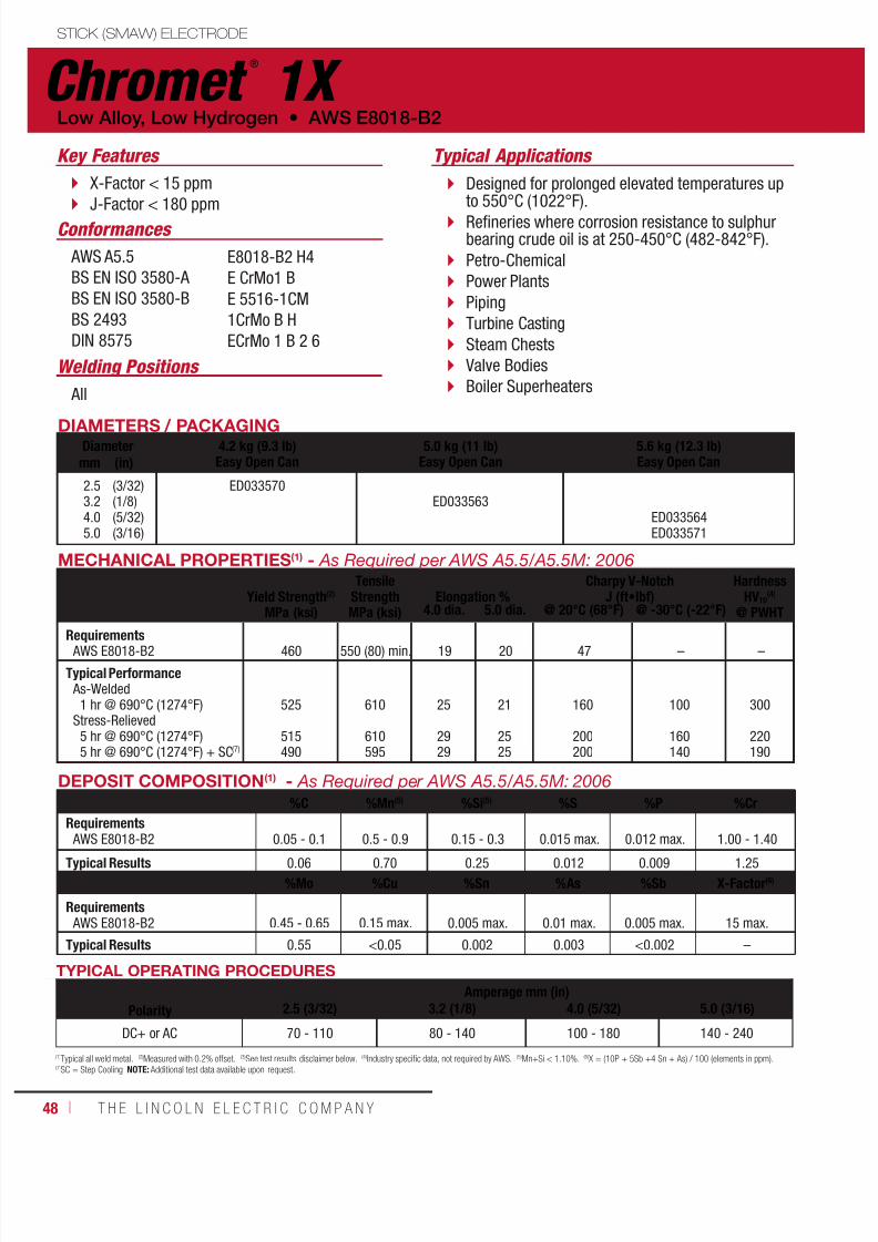
7/18/2019 c110 - Lincoln Electric Consumables 2014
http://slidepdf.com/reader/full/c110-lincoln-electric-consumables-2014 48/51148 ı T H E L I N C O L N E L E C T R I C C O M P A N Y
DIAMETERS / PACKAGINGDiameter 4.2 kg (9.3 lb)
Easy Open Can5.0 kg (11 lb)
Easy Open Can5.6 kg (12.3 lb)Easy Open Canmm (in)
2.53.24.05.0
(3/32)(1/8)(5/32)(3/16)
ED033570ED033563
ED033564ED033571
Typical ApplicationsKey Features
Welding Positions
Conformances
X-Factor < 15 ppm
J-Factor < 180 ppm
Designed for prolonged elevated temperatures upto 550°C (1022°F).
Refineries where corrosion resistance to sulphurbearing crude oil is at 250-450°C (482-842°F).
Petro-Chemical
Power Plants
Piping
Turbine Casting
Steam Chests
Valve Bodies
Boiler Superheaters
AWS A5.5
BS EN ISO 3580-A
BS EN ISO 3580-B
BS 2493
DIN 8575
E8018-B2 H4
E CrMo1 B
E 5516-1CM
1CrMo B H
ECrMo 1 B 2 6
All
TYPICAL OPERATING PROCEDURES
PolarityAmperage mm (in)
2.5 (3/32) 3.2 (1/8) 4.0 (5/32) 5.0 (3/16)
DC+ or AC 70 - 110 80 - 140 100 - 180 140 - 240
DEPOSIT COMPOSITION(1) - As Required per AWS A5.5/A5.5M: 2006
%C %Mn(5) %Si(5) %S %P %Cr
Requirements AWS E8018-B2 0.05 - 0.1 0.5 - 0.9 0.15 - 0.3 0.015 max. 0.012 max. 1.00 - 1.40
Typical Results 0.06 0.70 0.25 0.012 0.009 1.25
%Mo %Cu %Sn %As %Sb X-Factor(6)
Requirements AWS E8018-B2 0.45 - 0.65 0.15 max. 0.005 max. 0.01 max. 0.005 max. 15 max.
Typical Results 0.55 <0.05 0.002 0.003 <0.002 –
MECHANICAL PROPERTIES(1) - As Required per AWS A5.5/A5.5M: 2006
Yield Strength(2)
MPa (ksi)
TensileStrengthMPa (ksi)
Elongation %
Charpy V-NotchJ (ft•lbf)
HardnessHV10
(4)
@ PWHT4.0 dia. 5.0 dia. @ 20°C (68°F) @ -30°C (-22°F)
Requirements AWS E8018-B2 460 550 (80) min. 19 20 47 – –
Typical Performance As-Welded
1 hr @ 690°C (1274°F)Stress-Relieved
5 hr @ 690°C (1274°F)5 hr @ 690°C (1274°F) + SC(7)
525
515490
610
610595
25
2929
21
2525
160
200200
100
160140
300
220190
(1)
Typical all weld metal.(2)
Measured with 0.2% offset.(3)
See test results disclaimer below.(4)
Industry specific data, not required by AWS.(5)
Mn+Si < 1.10%.(6)
X = (10P + 5Sb +4 Sn + As) / 100 (elements in ppm).(7)SC = Step Cooling NOTE: Additional test data available upon request.
STICK (SMAW) ELECTRODE
Chromet ®
1X Low Alloy, Low Hydrogen • AWS E8018-B2

7/18/2019 c110 - Lincoln Electric Consumables 2014
http://slidepdf.com/reader/full/c110-lincoln-electric-consumables-2014 49/511W E L D I N G C O N S U M A B L E S C A TA L O G ı 49
STICK (SMAW) ELECTRODE
Chromet ®
2X AWS E9018-B3 • Low Alloy, Low Hydrogen
DIAMETERS / PACKAGINGDiameter 4.1 kg (9 lb)
Easy Open Can4.6 kg (10 lb)
Easy Open Can5.7 kg (13 lb)
Easy Open Canmm (in)
2.53.24.05.0
(3/32)(1/8)(5/32)(3/16)
ED033572ED033573
ED033574ED033575
Typical Applications Key Features
Welding Positions
Conformances
X-Factor < 15 ppm
J-Factor < 180 ppm
Designed for prolonged elevatedtemperatures up to 600°C (1112°F).
Refineries where corrosion resistance tosulphur bearing crude oil is at 250-450°C(482-842°F) .
Petro-Chemical
Power Plants
Piping
Turbine Casting
Steam Chests
Valve Bodies
Boiler Superheaters All
AWS A5.5BS EN ISO 3580-ABS EN ISO 3580-BBS 2493DIN 8575
E9018-B3
E CrMo1 B 3 2
E 6216-2C1M
2CrMo B H
ECrMo 2 B 2 6
TYPICAL OPERATING PROCEDURES
PolarityAmperage mm (in)
2.5 (3/32) 3.2 (1/8) 4.0 (5/32) 5.0 (3/16)
DC+ or AC 70 - 110 80 - 140 100 - 180 140 - 240
DEPOSIT COMPOSITION(1) - As Required per AWS A5.5/A5.5M: 2006
%C %Mn(5) %Si(5) %S %P %Cr
Requirements AWS E9018-B3 0.05 - 0.10 0.50 - 0.90 0.15 - 0.3 0.015 max. 0.012 max. 2.00 - 2.50
Typical Results 0.06 0.70 0.25 0.012 0.01 2.25
%Mo %Cu %Sn %As %Sb X-Factor(6)
Requirements AWS E9018-B3 0.90 - 1.20 0.15 max. 0.005 max. 0.010 max. 0.005 max. 15 max.
Typical Results 1.05 <0.05 0.002 0.003 <0.002 –
MECHANICAL PROPERTIES(1) - As Required per AWS A5.5/A5.5M: 2006
Yield Strength(2)
MPa (ksi)
TensileStrengthMPa (ksi)
Elongation %
Charpy V-NotchJ (ft•lbf)
HardnessHV10(4)
AW PWHT4.0 dia. 5.0 dia. @ 20°C (68°F) @ -30°C (-22°F)
Requirements AWS E9018-B3 540 min. 630 min. 17 min. 18 min. 47(2) min. – –
Typical Performance As-Welded
1 hr @ 690°C (1274°F)Stress-Relieved
5 hr @ 690°C (1274°F)5 hr @ 690°C (1274°F) + SC(7)
570
560550
670
660650
22
2725
19
2420
140
170170
80
140110
220 - 250
195205
(1)Typical all weld metal. (2)Measured with 0.2% offset. (3)See test results disclaimer below. (4)Industry specific data, not required by AWS. (5)Mn+Si < 1.10%. (6) X = (10P + 5Sb +4 Sn + As) / 100 (elements in ppm).
(7)SC = Step CoolingNOTE: Additional test data available upon request.

7/18/2019 c110 - Lincoln Electric Consumables 2014
http://slidepdf.com/reader/full/c110-lincoln-electric-consumables-2014 50/51150 ı T H E L I N C O L N E L E C T R I C C O M P A N Y
STICK (SMAW) ELECTRODE
Chromet ®
9-B9 Low Alloy, Low Hydrogen • AWS E9015-B9
DIAMETERS / PACKAGINGDiameter 4.5 kg (10 lb)
Easy Open Can5 kg (11 lb)
Easy Open Can5.5 kg (12 lb)
Easy Open Canmm (in)
2.53.24.05.0
(3/32)(1/8)(5/32)(3/16)
ED033379ED033380ED033381
ED033382
ApplicationsKey Features
Welding Positions
Conformances
Improved long term creep properties
Can weld equivalent (P91) 9CrMo steels
Intended for high integrity structural service atelevated temperature
Main Steam Piping
Power Plants
Oil Refineries
Coal Liquefaction Plants
Gasification Plants
All
AWS A5.5BS EN ISO 3580-B
E9015-B9E 6216-9C1MV
TYPICAL OPERATING PROCEDURES
PolarityAmperage mm (in)
2.5 (3/32) 3.2 (1/8) 4.0 (5/32) 5.0 (0.19)
DC+ or AC 70 - 110 80 - 140 100 - 180 140 - 240
DEPOSIT COMPOSITION(1) - As Required per AWS A5.5/A5.5M: 2006
%C %Mn(5) %Si(5) %S %P %Cr
Requirements AWS E9015-B9 0.08 - 0.12 0.40 - 0.75 0.30 max. 0.01 max. 0.01 max. 8.0 - 10.0
Typical Results(3) 0.10 0.55 0.25 0.008 0.008 9.0
%Ni(5) %Mo %Nb %V %Cu %Ai
Requirements AWS E9015-B9 0.2 - 0.4 0.85 - 1.2 0.03 - 0.07 0.15 - 0.25 0.25 max. 0.04 max.
Typical Results(3) 0.3 1.0 0.04 0.20 0.05 <0.01
MECHANICAL PROPERTIES(1) - As Required per AWS A5.5/A5.5M: 2006
Yield Strength(2)
MPa (ksi)
Tensile Strength
MPa (ksi)
Elongation %
Charpy V-NotchJ (ft•lbf)
HardnessHV10(4)
@ PWHT4.0 dia. 5.0 dia. @ 20°C (68°F)
Requirements AWS E9015-B9 530 (77) min. 620 (90) min. 17 min. 15 min. – –
Typical Results(3)
As-Welded2 hr @ 760°C (1400°F)
Stress-Relieved550°C (1022°F)600°C (1112°F)650°C (1202°F)
590 (86)
>360 (52)>255 (37)>175 (25)
710 (103)
>450 (65)>375 (54)>285 (41)
22.5
–––
19
>15>17>21
75 (55)
–––
450
–––
)Typical all weld metal. (2)Measured with 0.2% offset. (3)See test results disclaimer below. (4)Industry specific data, not required by AWS.5)Ni + Mn < 1.0%. Nickel is below 0.4% (as parent metal) although AWS allows up to 1.0%Ni. See Chromet 9MV-N or Chromet 9MVN+ for variant with 0.4 - 1.0%Ni conforming to BS EN ISO specification.
NOTE: Additional test data available upon request.

7/18/2019 c110 - Lincoln Electric Consumables 2014
http://slidepdf.com/reader/full/c110-lincoln-electric-consumables-2014 51/511W E L D I N G C O N S U M A B L E S ı 51
GMAW & GTAW CONSUMABLES
MIG WireMild Steel, BareSuperGlide® S3 ..............................................52
SuperGlide® S6 ..............................................54
Mild Steel, Copper CoatedSuperArc® L-50® ............................................56SuperArc® L-56® ............................................58SuperArc® L-59® ............................................60
Low Alloy, Copper CoatedSuperArc® LA-75 ............................................62SuperArc® LA-90 ............................................64SuperArc® LA-100 ..........................................66
TIG Cut LengthMild Steel, Copper CoatedLincoln® ER70S-2...........................................68Lincoln® ER70S-6...........................................699CrMoV-N ......................................................70
MIG & TIG

7/18/2019 c110 - Lincoln Electric Consumables 2014
http://slidepdf.com/reader/full/c110-lincoln-electric-consumables-2014 52/51152 ı T H E L I N C O L N E L E C T R I C C O M P A N Y
SuperGlide ®
S3 MIG (GMAW) WIRE
Welding Positions
Typical Applications
All
Clean to light mill scale base material
Sheet metal to 380-485 MPa (55-70 ksi) yieldstrength material
Pipeline
Pressure vessels
Structural steel
Moderate levels of manganese and siliconfor deoxidization of clean to light mill scalesurfaces
MicroGuard® Ultra provides superior feedingand arc stability
Supports short-circuiting, globular, axialspray and pulsed spray transfer
Conformances
Shielding Gas
100% CO2
75-95% Argon / Balance CO2
95-98% Argon / Balance O2
Flow Rate: 30-50 CFH
Mild Steel, Bare Wire • AWS ER70S-3
Key Features
AWS A5.18/A5.18M: 2005
ASME SFA-A5.18:CWB/CSA W48-06:
EN ISO 14341-B:
ER70S-3
ER70S-3ER49S-3
G 49A 2 C S3

7/18/2019 c110 - Lincoln Electric Consumables 2014
http://slidepdf.com/reader/full/c110-lincoln-electric-consumables-2014 53/511W E L D I N G C O N S U M A B L E S C A TA L O G ı 53
DIAMETERS / PACKAGING
Diameter 44 lb (20 kg)Fiber Spool 500 lb (227 kg)Accu-Trak® Drumin (mm)
0.035
0.045
(0.9)
(1.1)
ED028621
ED028622
ED030772
ED030773
MECHANICAL PROPERTIES(1) – As Required per AWS A5.18/A5.18M: 2005
Yield Strength(2) Tensile Strength ElongationCharpy V-Notch
J (ft•lbf)MPa (ksi) MPa (ksi) % @ -18°C (0°F) @ -29°C (-20°F)
Requirements - AWS ER70S-3
As-Welded with 100% CO2 400 (58) min. 485 (70) min. 22 min. 27 (20) min. Not Specified
Typical Results(3) - As-Welded with 100% CO2 405 (59) 510 (74) 26 100 (74) 87 (64)
WIRE COMPOSITION – As Required per AWS A5.18/A5.18M: 2005
%C %Mn %Si %S %P
Requirements - AWS ER70S-3 0.006-0.15 0.90-1.40 0.45-0.75 0.035 max. 0.025 max.
Typical Results(3) 0.07-0.10 1.15-1.27 0.52-0.59 0.002-0.008 0.005-0.013
%Cr %Mo %Ni %V %Cu
Requirements - AWS ER70S-3 0.15 max. 0.15 max. 0.15 max. 0.03 max. 0.50 max.
Typical Results(3) ≤ 0.03 ≤ 0.01 ≤ 0.04 < 0.01 0.02-0.04
SuperGlide ®
S3
MIG (GMAW) WIRE
(AWS ER70S-3)
(1)Typical all weld metal. (2)Measured with 0.2% offset. (3)See test results disclaimer on pg. 18. (4)CTWD (Contact Tip to Work Distance). Subtract 1/4 in (6.4 mm) to calculate Electrical Stickout.(5)Procedures in these areas are procedures for short circuiting mode using 100% CO
2. When using 75% Argon, 25% CO
2 for short circuit transfer, reduce voltage by 1 to 2 volts.
TYPICAL OPERATING PROCEDURES
Diameter, PolarityShielding Gas
CTWD(4)
mm (in)Wire Feed Speed Voltage
(volts)Approx. Current
(amps)Melt-Off Rate
m/min (in/min) kg/hr (lb/hr)
0.035 in (0.9 mm), DC+
Short Circuit Transfer
100% CO2(5)
9-12
(3/8-1/2)
2.5
3.8
6.4
(100)
(150)
(250)
18
19
22
80
120
175
0.7
1.1
1.8
(1.6)
(2.4)
(4.0)
Spray Transfer
90% Ar/10% CO2
12-19
(1/2-3/4)
9.5
12.7
15.2
(375)
(500)
(600)
23
29
30
195
230
275
2.7
3.6
4.4
(6.0)
(8.0)
(9.6)
0.045 in (1.1 mm), DC+
Short Circuit Transfer
100% CO2
(5)
12-19
(1/2-3/4)
3.2
3.8
5.1
(125)
(150)
(200)
19
20
21
145
165
200
1.5
1.8
2.4
(3.4)
(4.0)
(5.4)
Spray Transfer
90% Ar/10% CO2
12-19
(1/2-3/4)
8.9
12.1
12.7
(350)
(475)
(500)
27
30
30
285
335
340
4.2
5.7
6.0
(9.2)
(12.5)
(13.2)
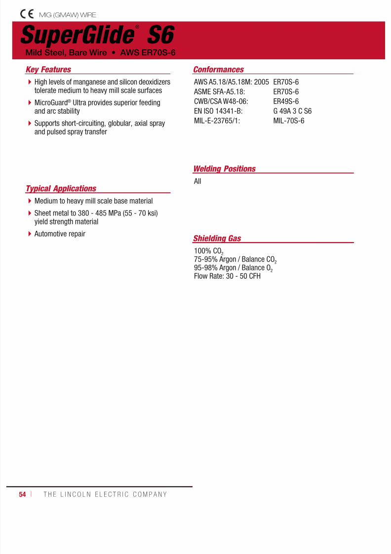
7/18/2019 c110 - Lincoln Electric Consumables 2014
http://slidepdf.com/reader/full/c110-lincoln-electric-consumables-2014 54/51154 ı T H E L I N C O L N E L E C T R I C C O M P A N Y
SuperGlide ®
S6
Welding Positions
Typical Applications
All
Medium to heavy mill scale base material
Sheet metal to 380 - 485 MPa (55 - 70 ksi)yield strength material
Automotive repair
High levels of manganese and silicon deoxidizerstolerate medium to heavy mill scale surfaces
MicroGuard® Ultra provides superior feedingand arc stability
Supports short-circuiting, globular, axial sprayand pulsed spray transfer
Conformances
Shielding Gas
100% CO2
75-95% Argon / Balance CO2
95-98% Argon / Balance O2
Flow Rate: 30 - 50 CFH
Mild Steel, Bare Wire • AWS ER70S-6
Key Features
AWS A5.18/A5.18M: 2005
ASME SFA-A5.18:CWB/CSA W48-06:
EN ISO 14341-B:
MIL-E-23765/1:
ER70S-6
ER70S-6ER49S-6
G 49A 3 C S6
MIL-70S-6
MIG (GMAW) WIRE

7/18/2019 c110 - Lincoln Electric Consumables 2014
http://slidepdf.com/reader/full/c110-lincoln-electric-consumables-2014 55/511W E L D I N G C O N S U M A B L E S C A TA L O G ı 55
DIAMETERS / PACKAGING
Diameter 44 lb (20 kg)Fiber Spool
900 lb (408 kg)Accu-Trak® Drumin (mm)
0.035
0.045
(0.9)
(1.1)
ED028635
ED028636
ED034560
ED034561
MECHANICAL PROPERTIES(1) – As Required per AWS A5.18/A5.18M: 2005
Yield Strength(2) Tensile Strength ElongationCharpy V-Notch
J (ft•lbf)MPa (ksi) MPa (ksi) % @ -29°C (-20°F)
Requirements(4) - AWS ER70S-6
As-Welded with 100% CO2
400 (58) min.
485 (70) min.
22 min.
27 (20) min.
Typical Results(3) - As-Welded with 100% CO2 430 (62) 540 (78) 28 71 (52)
SuperGlide ®
S6(AWS ER70S-6)
(1)Typical all weld metal. (2)Measured with 0.2% offset. (3)See test results disclaimer on pg. 18. (4)CTWD (Contact Tip to Work Distance). Subtract 1/4 in (6.4 mm) to calculate Electrical Stickout.(5)Procedures in these areas are procedures for short circuiting mode using 100% CO
2. When using 75% Argon, 25% CO
2 for short circuit transfer, reduce voltage by 1 to 2 volts.
WIRE COMPOSITION
%C %Mn %Si %S %P
Requirements - AWS ER70S-6 0.06-0.15 1.40-1.85 0.80-1.15 0.035 max. 0.025 max.
Typical Results(3) 0.08-0.09 1.42-1.65 0.81-0.87 0.006-0.010 0.004-0.010
%Cr %Ni %Mo %V %Cu (Total)
Requirements - AWS ER70S-6 0.15 max. 0.15 max. 0.15 max. 0.03 max. 0.50 max.
Typical Results(3) 0.01-0.05 ≤ 0.04 ≤ 0.01 < 0.01 0.01-0.04
TYPICAL OPERATING PROCEDURES
Diameter, PolarityShielding Gas
CTWD(4)
mm (in)Wire Feed Speed Voltage
(volts)Approx. Current
(amps)Melt-Off Rate
m/min (in/min) kg/hr (lb/hr)
0.035 in (0.9 mm), DC+
Short Circuit Transfer
100% CO2(5)
9-12
(3/8-1/2)
2.5
3.8
6.4
(100)
(150)
(250)
18
19
22
80
120
175
0.7
1.1
1.8
(1.6)
(2.4)
(4.0)
Spray Transfer
90% Ar/10% CO2
12-19
(1/2-3/4)
9.5
12.7
15.2
(375)
(500)
(600)
23
29
30
195
230
275
2.7
3.6
4.4
(6.0)
(8.0)
(9.6)
0.045 in (1.1 mm), DC+
Short Circuit Transfer
100% CO2
(5)
12-19
(1/2-3/4)
3.2
3.8
5.1
(125)
(150)
(200)
19
20
21
145
165
200
1.5
1.8
2.4
(3.4)
(4.0)
(5.4)
Spray Transfer
90% Ar/10% CO2
12-19
(1/2-3/4)
8.9
12.1
12.7
(350)
(475)
(500)
27
30
30
285
335
340
4.2
5.7
6.0
(9.2)
(12.5)
(13.2)
MIG (GMAW) WIRE
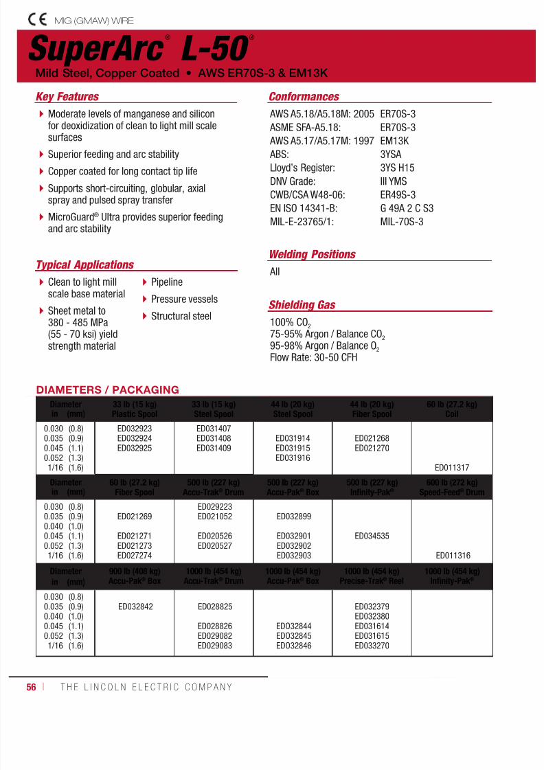
7/18/2019 c110 - Lincoln Electric Consumables 2014
http://slidepdf.com/reader/full/c110-lincoln-electric-consumables-2014 56/51156 ı T H E L I N C O L N E L E C T R I C C O M P A N Y
SuperArc ®
L-50 ®
Welding Positions
Typical Applications All Clean to light millscale base material
Sheet metal to380 - 485 MPa(55 - 70 ksi) yieldstrength material
Pipeline
Pressure vessels
Structural steel
Moderate levels of manganese and siliconfor deoxidization of clean to light mill scalesurfaces
Superior feeding and arc stability
Copper coated for long contact tip life
Supports short-circuiting, globular, axialspray and pulsed spray transfer
MicroGuard® Ultra provides superior feedingand arc stability
Conformances
Shielding Gas
100% CO2
75-95% Argon / Balance CO2
95-98% Argon / Balance O2
Flow Rate: 30-50 CFH
Mild Steel, Copper Coated • AWS ER70S-3 & EM13K
Key Features
AWS A5.18/A5.18M: 2005
ASME SFA-A5.18: AWS A5.17/A5.17M: 1997
ABS:
Lloyd’s Register:
DNV Grade:
CWB/CSA W48-06:
EN ISO 14341-B:
MIL-E-23765/1:
ER70S-3
ER70S-3EM13K
3YSA
3YS H15
III YMS
ER49S-3
G 49A 2 C S3
MIL-70S-3
DIAMETERS / PACKAGINGDiameter 33 lb (15 kg)Plastic Spool
33 lb (15 kg)Steel Spool
44 lb (20 kg)Steel Spool
44 lb (20 kg)Fiber Spool
60 lb (27.2 kg)Coilin (mm)
0.0300.0350.0450.0521/16
(0.8)(0.9)(1.1)(1.3)(1.6)
ED032923ED032924ED032925
ED031407ED031408ED031409
ED031914ED031915ED031916
ED021268ED021270
ED011317
Diameter 60 lb (27.2 kg)Fiber Spool
500 lb (227 kg)Accu-Trak® Drum
500 lb (227 kg)Accu-Pak® Box
500 lb (227 kg)Infinity-Pak®
600 lb (272 kg)Speed-Feed® Drumin (mm)
0.0300.035
0.0400.0450.0521/16
(0.8)(0.9)
(1.0)(1.1)(1.3)(1.6)
ED021269
ED021271ED021273ED027274
ED029223ED021052
ED020526ED020527
ED032899
ED032901 ED032902 ED032903
ED034535
ED011316
Diameter 900 lb (408 kg)Accu-Pak® Box
1000 lb (454 kg)Accu-Trak® Drum
1000 lb (454 kg)Accu-Pak® Box
1000 lb (454 kg)Precise-Trak® Reel
1000 lb (454 kg)Infinity-Pak® in (mm)
0.0300.0350.0400.0450.0521/16
(0.8)(0.9)(1.0)(1.1)(1.3)(1.6)
ED032842 ED028825
ED028826ED029082ED029083
EDO32844 EDO32845 EDO32846
ED032379ED032380ED031614ED031615ED033270
MIG (GMAW) WIRE
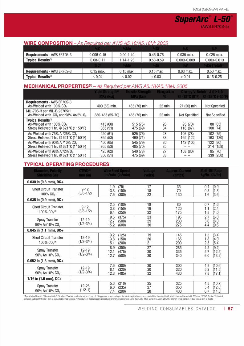
7/18/2019 c110 - Lincoln Electric Consumables 2014
http://slidepdf.com/reader/full/c110-lincoln-electric-consumables-2014 57/511W E L D I N G C O N S U M A B L E S C A TA L O G ı 57
MECHANICAL PROPERTIES(1) – As Required per AWS A5.18/A5.18M: 2005Yield Strength(2) Tensile Strength Elongation Charpy V-Notch - J (ft•lbf)
MPa (ksi) MPa (ksi) % @ -18°C (0°F) @ -29°C (-20°F)
Requirements - AWS ER70S-3 As-Welded with 100% CO2 400 (58) min. 485 (70) min. 22 min.
27 (20) min.
Not Specified
MIL-70S-3 per MIL-E-23765/1 As-Welded with CO2 and 98% Ar/2% O2 380-485 (55-70) 485 (70) min. 22 min. Not Specified Not Specified
Typical Results(3)
As-Welded with 100% CO2
Stress Relieved 1 hr. @ 621°C (1150°F)415 (60)365 (53)
515 (75)475 (69)
2634
95118
(70)(87)
88100
(65)(74)
As-Welded with 75% Ar/25% CO2
Stress Relieved 1 hr. @ 621°C (1150°F)420 (61)365 (53)
525 (76)490 (71)
2833
106165
(78)(122)
102163
(75)(120)
As-Welded with 90% Ar/10% CO2
Stress Relieved 1 hr. @ 621°C (1150°F)450 (65)365 (53)
545 (79)485 (70)
3035
142–
(105)–
122214
(90)(158)
As-Welded with 98% Ar/2% O2
Stress Relieved 1 hr. @ 621°C (1150°F)425 (62)350 (51)
540 (78)475 (69)
2733
108–
(80)–
95339
(70)(250)
SuperArc ®
L-50 ®
(AWS ER70S-3)
(1)Typical all weld metal. (2)Measured with 0.2% offset. (3)See test results disclaimer on pg. 18. (4)Copper due to any coating on the electrode plus the copper content of the filler metal itself, shall not exceed the stated 0.50% max. (5)CTWD (Contact Tip to WorkDistance). Subtract 1/4 in (6.4 mm) to calculate Electrical Stickout. (6)Procedures in these areas are procedures for short circuiting mode using 100% CO
2. When using 75% Argon, 25% CO
2 for short circuit transfer, reduce voltage by 1 to 2 volts.
TYPICAL OPERATING PROCEDURES
Diameter, PolarityShielding Gas
CTWD(5)
mm (in)Wire Feed Speed Voltage
(volts)Approx. Current
(amps)Melt-Off Rate
m/min (in/min) kg/hr (lb/hr)
0.030 in (0.8 mm), DC+
Short Circuit Transfer
100% CO2
9-12(3/8-1/2)
1.93.87.6
(75)(150)(300)
171822
3570130
0.40.81.6
(0.9)(1.8)(3.6)
0.035 in (0.9 mm), DC+
Short Circuit Transfer
100% CO2 (6)
9-12(3/8-1/2)
2.53.86.4
(100)(150)(250)
181922
80120175
0.71.11.8
(1.6)(2.4)(4.0)
Spray Transfer
90% Ar/10% CO2
12-19(1/2-3/4)
9.512.715.2
(375)(500)(600)
232930
195230275
2.73.64.4
(6.0)(8.0)(9.6)
0.045 in (1.1 mm), DC+
Short Circuit Transfer100% CO2
(6)12-19
(1/2-3/4)3.23.85.1
(125)(150)(200)
192021
145165200
1.51.82.5
(3.4)(4.0)(5.4)
Spray Transfer
90% Ar/10% CO2
12-19(1/2-3/4)
8.912.112.7
(350)(475)(500)
273030
285335340
4.25.76.0
(9.2)(12.5)(13.2)
0.052 in (1.3 mm), DC+
Spray Transfer
90% Ar/10% CO2
12-19(1/2-3/4)
7.68.1
12.3
(300)(320)(485)
303032
300320430
4.85.27.8
(10.6)(11.5)(17.1)
1/16 in (1.6 mm), DC+
Spray Transfer
90% Ar/10% CO2
12-25(1/2-1)
5.36.07.4
(210)(235)(290)
252728
325350430
4.85.46.7
(10.7)(12.0)(14.8)
MIG (GMAW) WIRE
WIRE COMPOSITION – As Required per AWS A5.18/A5.18M: 2005%C %Mn %Si %S %P
Requirements - AWS ER70S-3 0.006-0.15 0.90-1.40 0.45-0.75 0.035 max. 0.025 max.
Typical Results(3) 0.08-0.11 1.14-1.23 0.53-0.59 0.003-0.009 0.003-0.013%Cr %Mo %Ni %V %Cu (Total)(4)
Requirements - AWS ER70S-3 0.15 max. 0.15 max. 0.15 max. 0.03 max. 0.50 max.
Typical Results(3) ≤ 0.04 ≤ 0.02 ≤ 0.03 < 0.01 0.15-0.25
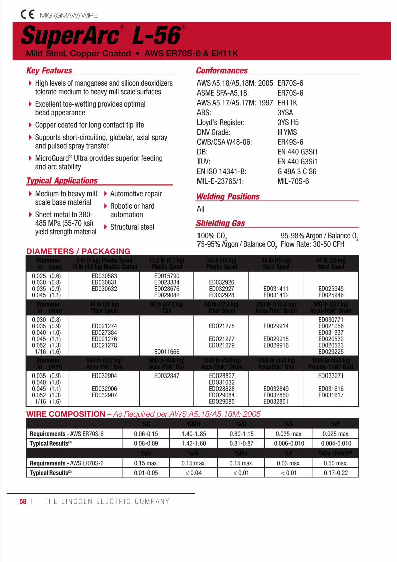
7/18/2019 c110 - Lincoln Electric Consumables 2014
http://slidepdf.com/reader/full/c110-lincoln-electric-consumables-2014 58/51158 ı T H E L I N C O L N E L E C T R I C C O M P A N Y
SuperArc ®
L-56 ®
Welding Positions
Typical Applications
All
Medium to heavy millscale base material
Sheet metal to 380-485 MPa (55-70 ksi)yield strength material
Automotive repair
Robotic or hardautomation
Structural steel
High levels of manganese and silicon deoxidizerstolerate medium to heavy mill scale surfaces
Excellent toe-wetting provides optimalbead appearance
Copper coated for long contact tip life
Supports short-circuiting, globular, axial sprayand pulsed spray transfer
MicroGuard® Ultra provides superior feedingand arc stability
Conformances
Shielding Gas
100% CO2
75-95% Argon / Balance CO2
95-98% Argon / Balance O2
Flow Rate: 30-50 CFH
Mild Steel, Copper Coated • AWS ER70S-6 & EH11K
Key Features
AWS A5.18/A5.18M: 2005
ASME SFA-A5.18: AWS A5.17/A5.17M: 1997
ABS:
Lloyd’s Register:
DNV Grade:
CWB/CSA W48-06:
DB:
TUV:
EN ISO 14341-B:
MIL-E-23765/1:
ER70S-6
ER70S-6EH11K
3YSA
3YS H5
III YMS
ER49S-6
EN 440 G3Si1
EN 440 G3Si1
G 49A 3 C S6
MIL-70S-6
DIAMETERS / PACKAGINGDiameter 2 lb (1 kg) Plastic Spool
10 lb (4.5 kg) Master Carton12.5 lb (5.7 kg)Plastic Spool
33 lb (15 kg)Plastic Spool
33 lb (15 kg)Steel Spool
44 lb (20 kg)Steel Spoolin (mm)
0.0250.030
0.0350.045
(0.6)(0.8)
(0.9)(1.1)
ED030583ED030631
ED030632
ED015790ED023334
ED028676ED029042
ED032926
ED032927ED032928
ED031411ED031412
ED025945ED025946
Diameter 44 lb (20 kg)Fiber Spool
60 lb (27.2 kg)Coil
60 lb (27.2 kg)Fiber Spool
250 lb (113.4 kg)Accu-Trak ® Drum
500 lb (227 kg)Accu-Trak ® Drumin (mm)
0.0300.0350.0400.0450.0521/16
(0.8)(0.9)(1.0)(1.1)(1.3)(1.6)
ED021274ED027384ED021276ED021278
ED011666
EDO21275
EDO21277EDO21279
ED029914
ED029915ED029916
ED030771ED021056ED031937ED020532ED020533ED029225
Diameter 500 lb (227 kg)Accu-Pak ® Box
900 lb (408 kg)Accu-Pak ® Box
1000 lb (454 kg)Accu-Trak ® Drum
1000 lb (454 kg)Accu-Pak ® Box
1000 lb (454 kg)Precise-Trak ® Reelin (mm)
0.035
0.0400.0450.0521/16
(0.9)
(1.0)(1.1)(1.3)(1.6)
ED032904
ED032906ED032907
ED032847 EDO28827
EDO31032EDO28828EDO29084EDO29085
ED032849ED032850ED032851
EDO33271
ED031616ED031617
WIRE COMPOSITION – As Required per AWS A5.18/A5.18M: 2005
%C %Mn %Si %S %P
Requirements - AWS ER70S-6 0.06-0.15 1.40-1.85 0.80-1.15 0.035 max. 0.025 max.
Typical Results(3) 0.08-0.09 1.42-1.60 0.81-0.87 0.006-0.010 0.004-0.010
%Cr %Ni %Mo %V %Cu (Total)(4)
Requirements - AWS ER70S-6 0.15 max. 0.15 max. 0.15 max. 0.03 max. 0.50 max.
Typical Results(3) 0.01-0.05 ≤ 0.04 ≤ 0.01 < 0.01 0.17-0.22
MIG (GMAW) WIRE

7/18/2019 c110 - Lincoln Electric Consumables 2014
http://slidepdf.com/reader/full/c110-lincoln-electric-consumables-2014 59/511W E L D I N G C O N S U M A B L E S C A TA L O G ı 59
MECHANICAL PROPERTIES(1) – As Required per AWS A5.18/A5.18M: 2005
Yield Strength(2) Tensile Strength ElongationCharpy V-Notch
J (ft•lbf)
MPa (ksi) MPa (ksi) % @ -29°C (-20°F) @ -40°C (-40°F)Requirements - AWS ER70S-6 As-Welded with 100% CO2 400 (58) min. 485 (70) min. 22 min. 27 (20) min. Not Specified
MIL-70S-6 per MIL-E-23765/1 As-Welded with CO2 and 98% Ar/2% O2 380-550 (55-80) 485 (70) min. 22 min. Not Specified Not Specified
MIL-70S-6 per MIL-E-23765/1Stress Relieved 1 hr. @ 621°C (1150° F)with CO2 and 98% Ar/2% O2 360 (52) min. 485 (70) min. 26 min. 27 (20) min. Not Specified
Typical Results(3)
As-Welded with 100% CO2
Stress Relieved 1 hr. @ 621°C (1150°F)440395
(64)(57)
560510
(81)(74)
2929
7195
(52)(70)
6168
(45)(50)
As-Welded with 75% Ar/25% CO2
Stress Relieved 1 hr. @ 621°C (1150°F)
460
415
(67)
(60)
565
540
(82)
(78)
27
31
82
140
(60)
(103)
72
122
(53)
(90) As-Welded with 90% Ar/10% CO2
Stress Relieved 1 hr. @ 621°C (1150°F)470440
(68)(64)
580550
(84)(80)
2832
119183
(88)(135)
78156
(57)(115)
As-Welded with 98% Ar/2% O2
Stress Relieved 1 hr. @ 621°C (1150°F)455415
(66)(60)
565545
(82)(79)
2734
122190
(90)(140)
108176
(80)(130)
(1)Typical all weld metal. (2)Measured with 0.2% offset. (3)See test results disclaimer on pg. 18. (4)Copper due to any coating on the electrode plus the copper content of t he filler metal itself, shall not exceed the stated 0.50% max. (5)CTWD (Contact Tip to WorkDistance). Subtract 1/4 in (6.4 mm) to calculate Electrical Stickout. (6)Procedures in these areas are procedures for short circuiting mode using 100% CO
2. When using 75% Argon, 25% CO
2 for short circuit transfer, reduce voltage by 1 to 2 volts.
TYPICAL OPERATING PROCEDURES
Diameter, PolarityShielding Gas
CTWD(5)
mm (in)Wire Feed Speed Voltage
(volts)Approx. Current
(amps)Melt-Off Rate
m/min (in/min) kg/hr (lb/hr)
0.025 in (0.6 mm), DC+Short Circuit Transfer
100% CO2
9-12(3/8-1/2)
2.56.4
(100)(250)
1719
3580
0.40.9
(0.9)(2.0)
0.030 in (0.8 mm), DC+
Short Circuit Transfer100% CO
2
9-12(3/8-1/2)
1.93.87.6
(75)(150)(300)
171822
3570130
0.40.81.6
(0.9)(1.8)(3.6)
0.035 in (0.9 mm), DC+
Short Circuit Transfer100% CO
2(6)
9-12(3/8-1/2)
2.53.86.4
(100)(150)(250)
181922
80120175
0.71.11.8
(1.6)(2.4)(4.0)
Spray Transfer90% Ar/10% CO
2
12-19(1/2-3/4)
9.512.715.2
(375)(500)(600)
232930
195230275
2.73.64.4
(6.0)(8.0)(9.6)
0.045 in (1.1 mm), DC+
Short Circuit Transfer
100% CO2(6)
12-19
(1/2-3/4)
3.2
3.85.1
(125)
(150)(200)
19
2021
145
165200
1.5
1.82.5
(3.4)
(4.0)(5.4)
Spray Transfer90% Ar/10% CO
2
12-19(1/2-3/4)
8.912.112.7
(350)(475)(500)
273030
285335340
4.25.76.0
(9.2)(12.5)(13.2)
0.052 in (1.3 mm), DC+
Spray Transfer90% Ar/10% CO
2
12-19(1/2-3/4)
7.68.1
12.3
(300)(320)(485)
303032
300320430
4.85.27.8
(10.7)(11.5)(17.1)
1/16 in (1.6 mm), DC+
Spray Transfer90% Ar/10% CO
2
12-25(1/2-1)
5.36.07.4
(210)(235)(290)
272829
325350430
4.85.46.7
(10.7)(12.0)(14.8)
MIG (GMAW) WIRE
SuperArc ®
L-56 ®
(AWS ER70S-6)

7/18/2019 c110 - Lincoln Electric Consumables 2014
http://slidepdf.com/reader/full/c110-lincoln-electric-consumables-2014 60/51160 ı T H E L I N C O L N E L E C T R I C C O M P A N Y
SuperArc ®
L-59 ®
Welding Positions
Typical Applications All
Robotic or hard automation
Automotive
Pipeline & Offshore
Pressure vessels
Heavy fabrication
Alternative to metal-cored wire
High deposition rates similar to metal-cored wire
Minimal spatter Engineered alloy system enhances siliconisland management
Copper coated for long contact tip life
Fast travel speeds
MicroGuard® Ultra provides superior feedingand arc stability
Conformances
Shielding Gas
100% CO2
75-95% Argon / Balance CO2
95-98% Argon / Balance O2
Flow Rate: 30 - 50 CFH
Mild Steel, Copper Coated • AWS ER70S-6
Key Features
AWS A5.18/A5.18M: 2005
ASME SFA-A5.18: ABS:
DNV Grade:
BV Grade:
CWB/CSA W48-06:
EN ISO 14341-B:
ER70S-6
ER70S-63YSA (100 C02 & Mixed)
III YMS H5 (Mixed)
SA3YHHH (Mixed)
ER49S-6
G 49A 3 C S6
DIAMETERS / PACKAGING
Diameter 33 lb (14.9 kg)Plastic Spool
44 lb (20 kg)Fiber Spool
44 lb (20 kg)Steel Spool
60 lb (27.2 kg)Fiber Spool
500 lb (227 kg)Accu-Pak® Boxin (mm)
0.035
0.0400.045
0.052
1/16
(0.9)
(1.0)(1.1)
(1.3)
(1.6)
ED034270
ED034271
ED034272
ED034356
ED033033 ED032366
ED032367
ED032368
ED032968
ED032814
ED032894
ED032895ED032896
ED032897
Diameter 900 lb (408 kg)Accu-Pak® Box
1000 lb (454 kg)Infinity-Pak®
1000 lb (454 kg)Accu-Pak® Box
1000 lb (454 kg)Precise-Trak® Reelin (mm)
0.035
0.040
0.045
0.052
1/16
(0.9)
(1.0)
(1.1)
(1.3)
(1.6)
ED032861
ED032863
ED032864
ED032865
ED032808
ED032809
MIG (GMAW) WIRE

7/18/2019 c110 - Lincoln Electric Consumables 2014
http://slidepdf.com/reader/full/c110-lincoln-electric-consumables-2014 61/511W E L D I N G C O N S U M A B L E S C A TA L O G ı 61
MECHANICAL PROPERTIES(1)
Yield Strength(2) Tensile Strength Elongation
Charpy V-Notch
J (ft•lbf)MPa (ksi) MPa (ksi) % @ -29°C (-20°F) @ -40°C (-40°F)
Requirements - AWS ER70S-6
As-Welded with 100% CO2
400 (58) min.
485 (70) min.
22 min.
27 (20) min.
Not Specified
Typical Results(3)
As-Welded with 100% CO2
As-Welded with 75% Ar/25% CO2
As-Welded with 90% Ar/10% CO2
455
485
460
(66)
(70)
(67)
565
595
570
(82)
(86)
(83)
28
25
25
71
56
75
(52)
(41)
(55)
53
53
65
(39)
(39)
(48)
WIRE COMPOSITION – As Required per AWS A5.18/A5.18M: 2005
%C %Mn %Si %S %P
Requirements - AWS ER70S-6 0.06-0.15 1.40-1.85 0.80-1.15 0.035 max. 0.025 max.
%Cu(4) %Ni %Cr %Mo %V
Requirements - AWS ER70S-6 0.50 max. 0.15 max. 0.15 max. 0.15 max. 0.03 max.
(1)Typical all weld metal. (2)Measured with 0.2% offset. (3)See test results disclaimer on pg. 18. (4)Copper due to any coating on the electrode plus the copper content of the filler metal itself, shall not exceed the stated 0.50% max. (5)CTWD (Contact Tip to Work Distance).Subtract 1/4 in (6.4 mm) to calculate Electrical Stickout. (6)Procedures in these areas are procedures for short circuiting mode using 75% Argon, 25% CO
2. NOTE: For 100% CO
2 procedures, add 1 to 2 volts for short circuit transfer and 2 to 3 volts for globular transfer.
TYPICAL OPERATING PROCEDURES
Diameter, PolarityShielding Gas
CTWD(5)
mm (in)Wire Feed Speed Voltage
(volts)Approx. Current
(amps)Melt-Off Rate
m/min (in/min) kg/hr (lb/hr)
0.035 in (0.9 mm), DC+
Short Circuit Transfer
75% Ar/25% CO2
(6)
12
(1/2)
2.5
3.8
6.4
(100)
(150)
(250)
17
18
20
80
120
175
0.7
1.1
1.8
(1.6)
(2.4)
(4.0)
Spray Transfer
90% Ar/10% CO2
19
(3/4)
9.5
12.7
15.2
(375)
(500)
(600)
23
29
30
195
230
275
2.7
3.6
4.4
(6.0)
(8.0)
(9.6)
0.045 in (1.1 mm), DC+
Short Circuit Transfer
75% Ar/25% CO2
(6)
12
(1/2)
3.2
3.8
5.1
(125)
(150)
(200)
18
19
20
145
165
200
1.5
1.8
2.4
(3.4)
(4.0)
(5.4)
Spray Transfer
90% Ar/10% CO2
19
(3/4)
8.912.1
12.7
(350)(475)
(500)
2730
30
285335
340
4.25.7
6.0
(9.2)(12.5)
(13.2)
0.052 in (1.3 mm), DC+
Spray Transfer
90% Ar/10% CO2
19
(3/4)
7.6
8.1
12.3
(300)
(320)
(485)
30
30
32
300
320
430
4.8
5.2
7.8
(10.6)
(11.5)
(17.1)
1/16 in (1.6 mm), DC+
Spray Transfer
90% Ar/10% CO2
19
(3/4)
5.3
6.0
7.4
(210)
(235)
(290)
25
27
28
325
350
430
4.8
5.4
6.7
(10.7)
(12.0)
(14.8)
SuperArc ®
L-59 ®
(AWS ER70S-6)
MIG (GMAW) WIRE
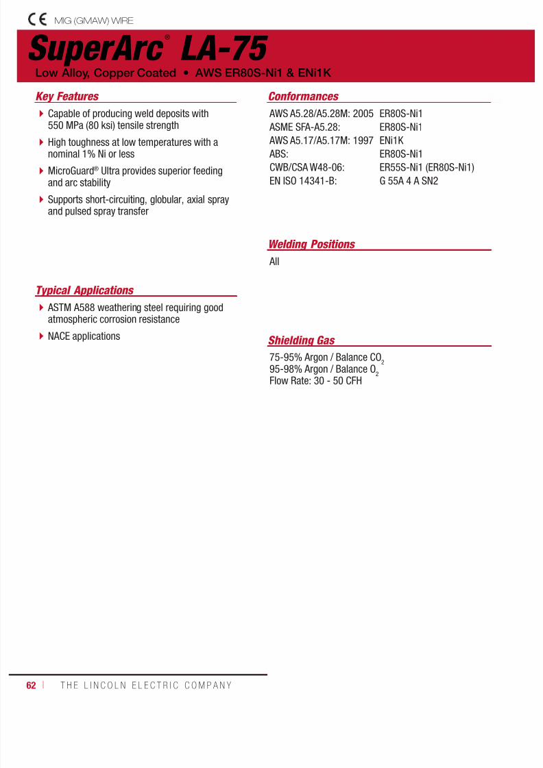
7/18/2019 c110 - Lincoln Electric Consumables 2014
http://slidepdf.com/reader/full/c110-lincoln-electric-consumables-2014 62/51162 ı T H E L I N C O L N E L E C T R I C C O M P A N Y
SuperArc ®
LA-75
Welding Positions
Typical Applications
All
ASTM A588 weathering steel requiring goodatmospheric corrosion resistance
NACE applications
Capable of producing weld deposits with550 MPa (80 ksi) tensile strength
High toughness at low temperatures with anominal 1% Ni or less
MicroGuard® Ultra provides superior feedingand arc stability
Supports short-circuiting, globular, axial sprayand pulsed spray transfer
Conformances
Shielding Gas
75-95% Argon / Balance CO2
95-98% Argon / Balance O2
Flow Rate: 30 - 50 CFH
Low Alloy, Copper Coated • AWS ER80S-Ni1 & ENi1K
Key Features
AWS A5.28/A5.28M: 2005
ASME SFA-A5.28: AWS A5.17/A5.17M: 1997
ABS:
CWB/CSA W48-06:
EN ISO 14341-B:
ER80S-Ni1
ER80S-Ni1ENi1K
ER80S-Ni1
ER55S-Ni1 (ER80S-Ni1)
G 55A 4 A SN2
MIG (GMAW) WIRE
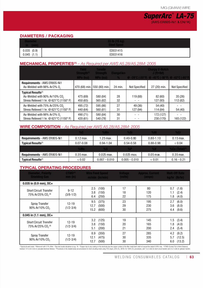
7/18/2019 c110 - Lincoln Electric Consumables 2014
http://slidepdf.com/reader/full/c110-lincoln-electric-consumables-2014 63/511W E L D I N G C O N S U M A B L E S C A TA L O G ı 63
DIAMETERS / PACKAGING
Diameter 33 lb (15 kg)Steel Spoolin (mm)
0.0350.045
(0.9)(1.1)
ED031415ED031416
MECHANICAL PROPERTIES(1) – As Required per AWS A5.28/A5.28M: 2005
YieldStrength(2)
TensileStrength Elongation
Charpy V-NotchJ (ft•lbf)
MPa (ksi) MPa (ksi) % @ -29°C (-20°F) @ -45°C (-50°F) @ -62°C (-80°F)
Requirements - AWS ER80S-Ni1
As-Welded with 98% Ar/2% O2
470 (68) min.
550 (80) min.
24 min.
Not Specified
27 (20) min.
Not Specified
Typical Results(3)
As-Welded with 90% Ar/10% CO2
Stress Relieved 1 hr. @ 621°C (1150° F)
475
450
(69)
(65)
580
565
(84)
(82)
28
32
119
-
(88)
-
82
127
(60)
(93)
35
112
(26)
(82)
As-Welded with 75% Ar/25% CO2
Stress Relieved 1 hr. @ 621°C (1150° F)
495
440
(72)
(64)
595
560
(86)
(81)
27
31
49
127
(36)
(94)
54
114
(40)
(84)
-
54
-
(40)
As-Welded with 98% Ar/2% O2
Stress Relieved 1 hr. @ 621°C (1150° F)
490
420
(71)
(61)
580
540
(84)
(78)
30
31
-
-
-
-
172
230
(127)
(170)
-
165
-
(122)
SuperArc ®
LA-75(AWS ER80S-Ni1 & ENi1K)
WIRE COMPOSITION – As Required per AWS A5.28/A5.28M: 2005
%C %Mn %Si %Ni %Cr
Requirements - AWS ER80S-Ni1 0.12 max. 1.25 max. 0.40-0.80 0.80-1.10 0.15 max.
Typical Results(3) 0.07-0.08 0.94-1.04 0.54-0.58 0.88-0.98 ≤ 0.04
%Mo %S %P %V %Cu (Total)(4)
Requirements - AWS ER80S-Ni1 0.35 max. 0.025 max. 0.025 max. 0.05 max. 0.35 max.
Typical Results(3) ≤ 0.02 0.007 - 0.010 0.005 - 0.010 < 0.01 0.16 - 0.21
(1)Typical all weld metal. (2)Measured with 0.2% offset. (3)See test results disclaimer on pg. 18. (4)Copper due to any coating on the electrode plus the copper content of the filler metal itself, shall not exceed the stated 0.50% max. (5)CTWD (Contact Tip to Work Distance).Subtract 1/4 in (6.4 mm) to calculate Electrical Stickout. (6)Procedures in the shaded areas are procedures for short circuiting mode using 75% Argon, 25% CO
2. NOTE: For 100% CO
2 procedures, add 1 to 2 volts for short circuit transfer and 2 to 3 volts for globular transfer.
TYPICAL OPERATING PROCEDURES
Diameter, PolarityShielding Gas
CTWD(5)
mm (in)Wire Feed Speed Voltage
(volts)Approx. Current
(amps)Melt-Off Rate
m/min (in/min) kg/hr (lb/hr)
0.035 in (0.9 mm), DC+
Short Circuit Transfer
75% Ar/25% CO2
(6)
9-12
(3/8-1/2)
2.5
3.8
6.4
(100)
(150)
(250)
17
18
22
80
120
175
0.7
1.1
1.8
(1.6)
(2.4)
(4.0)
Spray Transfer
90% Ar/10% CO2
12-19
(1/2-3/4)
9.5
12.7
15.2
(375)
(500)
(600)
23
29
30
195
230
275
2.7
3.6
4.4
(6.0)
(8.0)
(9.6)
0.045 in (1.1 mm), DC+
Short Circuit Transfer
75% Ar/25% CO2 (6)
12-19
(1/2-3/4)
3.2
3.8
5.1
(125)
(150)
(200)
19
20
21
145
165
200
1.5
1.8
2.4
(3.4)
(4.0)
(5.4)
Spray Transfer
90% Ar/10% CO2
12-19
(1/2-3/4)
8.9
12.1
12.7
(350)
(475)
(500)
27
30
30
285
335
340
4.2
5.7
6.0
(9.2)
(12.5)
(13.2)
MIG (GMAW) WIRE

7/18/2019 c110 - Lincoln Electric Consumables 2014
http://slidepdf.com/reader/full/c110-lincoln-electric-consumables-2014 64/51164 ı T H E L I N C O L N E L E C T R I C C O M P A N Y
SuperArc ®
LA-90
Welding Positions
Typical Applications
All
Requirements for strength after stressrelieving
ASTM A182, A217, A234 and A335 hightemperature service pipe, fittings, flangesand valves
ASTM A336 pressure vessel forgings
Capable of producing weld deposits with550 - 620 MPa (80 - 90 ksi) tensile strength
Contains 0.50% molybdenum for strengthafter stress-relief
MicroGuard® Ultra provides superior feedingand arc stability
Supports short-circuiting, globular, axial sprayand pulsed spray transfer
Conformances
Shielding Gas
100% CO2
75-95% Argon / Balance CO2
95-98% Argon / Balance O2
Flow Rate: 30 - 50 CFH
Low Alloy, Copper Coated • AWS ER80S-D2, ER90S-D2 & EA3K
Key Features
AWS A5.28/A5.28M: 2005
ASME SFA-A5.28:
AWS A5.23/A5.23M: 2007
CWB/CSA W48-06:
EN ISO 16484-B:
EN ISO 16834-B:
MIL-E-23765/2:
ER80S-D2 (100% CO2),
ER90S-D2 (Mixed)
ER80S-D2 (100% CO2),
ER90S-D2 (Mixed)
EA3K
ER55S-D2 (ER80S-D2),ER62S-D2 (ER90S-D2)
G 59A 3 C 4M31
G 62A 3 A 4M31
MIL-80S-3
DIAMETERS / PACKAGING
Diameter 33 lb (15 kg)Steel Spool
44 lb (20 kg)Steel Spool
44 lb (20 kg)Fiber Spoolin (mm)
0.035
0.045
0.052
1/16
(0.9)
(1.1)
(1.3)
(1.6)
ED031413
ED031414
EDS30775
EDS30776
EDS30777
ED029546
Diameter 60 lb (27.2 kg)
Coil
60 lb (27.2 kg)
Fiber Spool
500 lb (227 kg)
Accu-Trak
®
Drumin (mm)0.035
0.045
0.052
1/16
(0.9)
(1.1)
(1.3)
(1.6) ED013999
EDS01380
EDS01372
EDO01378
ED026627
Diameter 500 lb (227 kg)Accu-Pak® Box
1000 lb (454 kg)Accu-Trak® Drum
1000 lb (454 kg)Infinity-Pak®in (mm)
0.035
0.045
0.052
1/16
(0.9)
(1.1)
(1.3)
(1.6)
EDO32919
ED032920
EDS29590
ED029591
EDS29592
MIG (GMAW) WIRE

7/18/2019 c110 - Lincoln Electric Consumables 2014
http://slidepdf.com/reader/full/c110-lincoln-electric-consumables-2014 65/511W E L D I N G C O N S U M A B L E S C A TA L O G ı 65
SuperArc ®
LA-90(AWS ER80S-D2, ER90S-D2 & EA3K)
MECHANICAL PROPERTIES(1) – As Required per AWS A5.28/A5.28M: 2005
YieldStrength(2)
TensileStrength Elongation
Charpy V-NotchJ (ft•lbf)
MPa (ksi) MPa (ksi) % @ -29°C (-20°F) @ -40°C (-40°F)Requirements - AWS ER80S-D2
As-Welded with 100% CO2 470 (68) min. 550 (80) min. 17 min. 27 (20) min. Not Specified
AWS ER90S-D2
As-Welded with 95-99% Ar/Balance O2 540 (78) min. 620 (90) min. 17 min. 27 (20) min. Not Specified
Typical Results(3)
As-Welded with 100% CO2
As-Welded with 95% Ar/5% O2
As-Welded with 75% Ar/25% CO2
560
650
620
(81)
(94)
(90)
655
730
705
(95)
(106)
(102)
23
25
26
36
125
124
(26)
(92)
(91)
-
-
122
-
-
(90)
WIRE COMPOSITION – As Required per AWS A5.28/A5.28M: 2005
%C %Mn %Si %NiRequirements - AWS ER80S-D2, ER90S-D2 0.07-0.12 1.60-2.10 0.50-0.80 0.15 max.
Typical Results(3) 0.09-0.11 1.63-1.74 0.56-0.64 ≤ 0.04
%Mo %S %P %Cu (Total)(4)
Requirements - AWS ER80S-D2, ER90S-D2 0.40-0.60 0.025 max. 0.025 max. 0.50 max.
Typical Results(3) 0.43-0.46 ≤ 0.010 0.007-0.016 0.16-0.22
(1)Typical all weld metal. (2)Measured with 0.2% offset. (3)See test results disclaimer on pg. 18. (4)Copper due to any coating on the electrode plus the copper content of the filler metal itself, shall not exceed the stated 0.50% max. (5)CTWD (Contact Tip to Work Distance).Subtract 1/4 in (6.4 mm) to calculate Electrical Stickout. (6)Procedures in these areas are procedures for short circuiting mode using 75% Argon, 25% CO
2. NOTE: For 100% CO
2 procedures, add 1 to 2 volts for short circuit transfer and 2 to 3 volts for globular transfer.
TYPICAL OPERATING PROCEDURES
Diameter, PolarityShielding Gas
CTWD(5)
mm (in)Wire Feed Speed Voltage
(volts)Approx. Current
(amps)Melt-Off Rate
m/min (in/min) kg/hr (lb/hr)
0.035 in (0.9 mm), DC+
Short Circuit Transfer
75% Ar/25% CO2
(6)
9-12
(3/8-1/2)
2.5
3.8
6.4
(100)
(150)
(250)
18
19
22
80
120
175
0.7
1.1
1.8
(1.6)
(2.4)
(4.0)
Spray Transfer
90% Ar/10% CO2
12-19
(1/2-3/4)
9.5
12.7
15.2
(375)
(500)
(600)
23
29
30
195
230
275
2.7
3.6
4.4
(6.0)
(8.0)
(9.6)
0.045 in (1.1 mm), DC+
Short Circuit Transfer
75% Ar/25% CO2
(6)
12-19
(1/2-3/4)
3.2
3.8
5.1
(125)
(150)
(200)
19
20
21
145
165
200
1.5
1.8
2.5
(3.4)
(4.0)
(5.4)
Spray Transfer
90% Ar/10% CO2
12-19
(1/2-3/4)
8.912.1
12.7
(350)(475)
(500)
2730
30
285335
340
4.25.7
6.0
(9.2)(12.5)
(13.2)
0.052 in (1.3 mm), DC+
Spray Transfer
90% Ar/10% CO2
12-19
(1/2-3/4)
7.6
8.1
12.3
(300)
(320)
(485)
30
30
32
300
320
430
4.8
5.2
7.8
(10.6)
(11.5)
(17.1)
1/16 in (1.6 mm), DC+
Spray Transfer
90% Ar/10% CO2
12-25
(1/2-1)
5.3
6.0
7.4
(210)
(235)
(290)
25
27
28
325
350
430
4.8
5.4
6.7
(10.7)
(12.0)
(14.8)
MIG (GMAW) WIRE

7/18/2019 c110 - Lincoln Electric Consumables 2014
http://slidepdf.com/reader/full/c110-lincoln-electric-consumables-2014 66/51166 ı T H E L I N C O L N E L E C T R I C C O M P A N Y
SuperArc ®
LA-100
Welding Positions
Typical Applications
All
HY-80 base material ASTM A514, A543, A724 and A782quenched and tempered plate
Various heat input conditions
Military low alloy applications
Capable of producing welds with 690 MPa(100 ksi) tensile strength
Excellent for welding quenched and temperedsteels and HY-80 base materials
MicroGuard® Ultra provides superior feedingand arc stability
Supports short-circuiting, globular, axial sprayand pulsed spray transfer
Conformances
Shielding Gas
90-95% Argon / Balance CO2
95-98% Argon / Balance O2
Flow Rate: 30 - 50 CFH
Low Alloy, Copper Coated • AWS ER100S-G, ER110S-G & EM2
Key Features
AWS A5.28/A5.28M: 2005
ASME SFA-A5.28: AWS A5.23/A5.23M: 2007
ABS:
CWB/CSA W48-06:
DB:
TUV:
EN ISO 16834-B:
MIL-E-23765/2:
ER100S-G, ER110S-G
ER100S-G, ER110S-GEM2
4YQ550SA
ER69S-G (ER100S-G)
EN 12534 T 69 5 Mn3Ni1,5 Mo
EN 12534 T 69 5 Mn3Ni1,5 Mo
G 69A 5 A N3M2
MIL-100S-1
DIAMETERS / PACKAGING
Diameter 33 lb (15 kg)Steel Spool
44 lb (20 kg)Steel Spool
60 lb (27.2 kg)Coil
500 lb (227 kg)Accu-Trak® Drumin (mm)
0.035
0.045
1/16
(0.9)
(1.1)
(1.6)
ED031417
EDS30778
EDS30779
ED010996
ED031445
EDS01162
WIRE COMPOSITION – As Required per AWS A5.28/A5.28M: 2005
%C %Mn %Si %Ni %MoRequirements - AWS ER100S-G, ER110S-G - - - (A) (A)
Typical Results(3) 0.05-0.06 1.63-1.69 0.46-0.50 1.88-1.96 0.43-0.45
%Cr %S %P %V %Al
Requirements - AWS ER100S-G, ER110S-G (A) - - - -
Typical Results(3) 0.04-0.06 0.002-0.005 0.005-0.009 ≤ 0.01 ≤ 0.01
%Ti %Zr %Cu
Requirements - AWS ER100S-G, ER110S-G - - -
Typical Results(3) 0.03-0.04 ≤ 0.01 0.11-0.14
(A) Must have the minimum of one or more of the following: 0.50% Ni, 0.30% Cr, or 0.20% Mo.
MIG (GMAW) WIRE

7/18/2019 c110 - Lincoln Electric Consumables 2014
http://slidepdf.com/reader/full/c110-lincoln-electric-consumables-2014 67/511W E L D I N G C O N S U M A B L E S C A TA L O G ı 67
SuperArc ®
LA-100(AWS ER100S-G, ER110S-G & EM2)
MECHANICAL PROPERTIES(1) – As Required per AWS A5.28/A5.28M: 2005
YieldStrength(2)
TensileStrength Elongation
Charpy V-NotchJ (ft•lbf)
MPa (ksi) MPa (ksi) % @ -18°C (0°F) @ -51°C (-60°F)
Requirements - AWS ER100S-G
As-Welded - Gas Not Specified
Not Specified
690 (100) min.
Not Specified
Not Specified
Not Specified
AWS ER110S-G
As-Welded - Gas Not Specified Not Specified 760 (110) min. Not Specified Not Specified Not Specified
MIL-100S-1 per MIL-E-23765/2C, 2D, 2E
& T9074-BC-G1B-010/0200 As-Welded with 98% Ar /2% O2 565-825 (82-120) Not Specified 16 min. 81 (60) min. 47 (35) min.
Typical Results(3)
As-Welded at 30 kJ/in with 95% Ar/5% CO2
As-Welded at 45 kJ/in with 98% Ar/2% O2
750
730
(109)
(106)
790
780
(115)
(114)
22
20
164
-
(121)
-
138
118
(102)
(87)
Pulse
As-Welded at 110 kJ/in with 95% Ar/5% CO2 580 (84) 745 (108) 25 138 (102) 70 (52)
CV
As-Welded at 110 kJ/in with 95% Ar/5% CO2 620 (90) 740 (107) 25 170 (125) 106 (78)
As-Welded at 45 kJ/in with 95% Ar/5% CO2 682 (99) 765 (111) 20 - - 117 (86)
(1)Typical all weld metal. (2)Measured with 0.2% offset. (3)See test results disclaimer on pg. 18. (4)CTWD (Contact Tip to Work Distance). Subtract 1/4 in (6.4 mm) to calculate Electrical Stickout.(5)Procedures in this area are for pulse MIG mode for welding in the vertical up and overhead welding positions. Actual results are dependent on joint, material thickness, as well as wave shape and pulse frequency.
TYPICAL OPERATING PROCEDURES
Diameter, PolarityShielding Gas
CTWD(5)
mm (in)Wire Feed Speed Voltage
(volts)Approx. Current
(amps)Melt-Off Rate
m/min (in/min) kg/hr (lb/hr)
0.035 in (0.9 mm), DC+
Short Circuit Transfer
90% Ar/25% CO2
9-12
(3/8-1/2)
2.5
3.8
6.4
(100)
(150)
(250)
18
19
22
80
120
175
0.7
1.1
1.8
(1.6)
(2.4)
(4.0)
Spray Transfer
90% Ar/10% CO2
9-12
(3/8-1/2)
9.5
12.7
15.2
(375)
(500)
(600)
23
29
30
195
230
275
2.7
3.6
4.4
(6.0)
(8.0)
(9.6)
0.045 in (1.1 mm), DC+
Pulsed Spray Transfer(5)12-19
(1/2-3/4)
5.1
6.4
(200)
(250)
19-21
20-23
130
140
2.4
3.0
(5.4)
(6.7)
Spray Transfer
98% Ar/2% O2
95% Ar/5% CO2
12-19
(1/2-3/4)
8.9
12.1
12.7
(350)
(475)
(500)
27
30
30
285
335
340
4.2
5.7
6.0
(9.2)
(12.5)
(13.2)
0.052 in (1.3 mm), DC+
Spray Transfer
98% Ar/2% O2
95% Ar/5% CO2
12-25 (1/2-1)
12-25 (1/2-1)
5.3
6.0
7.4
(210)
(235)
(290)
25
27
28
325
350
430
4.8
5.4
6.7
(10.7)
(12.0)
(14.8)
MIG (GMAW) WIRE

7/18/2019 c110 - Lincoln Electric Consumables 2014
http://slidepdf.com/reader/full/c110-lincoln-electric-consumables-2014 68/51168 ı T H E L I N C O L N E L E C T R I C C O M P A N Y
TIG (GTAW) CUT LENGTHS
Lincoln ®
ER70S-2
Welding Positions
Typical Applications
All
Repairs on a variety of mild and low alloy steel
Small diameter pipe and tubing
Sheet metal applications
Root pass pipe welding
Contains zirconium, titanium, and aluminumin addition to silicon and manganese
Produces x-ray quality welds over mostsurface conditions
Recommended for TIG welding on all gradesof steel
Ink jet printing identification on entire lengthof electrode
Q2 Lot® - Certificates showing actual wirechemistry available online
Conformances
Mild Steel Cut Length • AWS ER70S-2
Key Features
AWS A5.18/A5.18M: 2005
ASME SFA-A5.18:
ER70S-2
ER70S-2
DIAMETERS / PACKAGING
Diameter 5 lb (2.3 kg) Plastic Tube20 lb (9.1 kg) Master Carton
10 lb (4.5 kg) Plastic Tube30 lb (13.6 kg) Master Carton
50 lb (22.7 kg)Cartonin (mm)
1/16
3/32
1/8
(1.6)
(2.4)
(3.2)
ED034325
ED034326
ED034327
ED034328
ED034329
ED034330
ED034331
ED034332
ED034333
WIRE COMPOSITION – As Required per AWS A5.18/A5.18M: 2005
%C %Mn %S %Si %P %Cu %Cr
Requirements - AWS ER70S-2 0.07 max. 0.90-1.40 0.035 max. 0.40-0.70 0.0025 max. 0.50 max. (1)
Typical Results(2) 0.04 1.08 0.005 0.55 0.0003 0.20 0.08
%Ni %Mo %V %Al %Ti %Zr
Requirements - AWS ER70S-2 (1) (1) (1) 0.05-0.15 0.05-0.15 0.02-0.12
Typical Results(2) 0.08 0.08 < 0.002 0.08 0.10 0.07
(1)Total 0.50% maximum, combined. (2)See test results disclaimer on pg. 18.
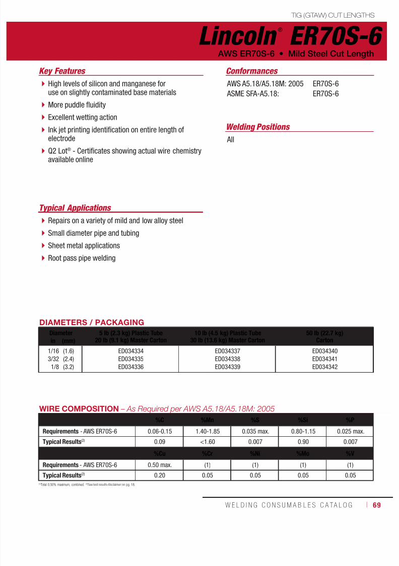
7/18/2019 c110 - Lincoln Electric Consumables 2014
http://slidepdf.com/reader/full/c110-lincoln-electric-consumables-2014 69/511W E L D I N G C O N S U M A B L E S C A TA L O G ı 69
TIG (GTAW) CUT LENGTHS
Lincoln ®
ER70S-6
Welding Positions
Typical Applications
All
Repairs on a variety of mild and low alloy steel
Small diameter pipe and tubing
Sheet metal applications
Root pass pipe welding
High levels of silicon and manganese foruse on slightly contaminated base materials
More puddle fluidity
Excellent wetting action
Ink jet printing identification on entire length ofelectrode
Q2 Lot® - Certificates showing actual wire chemistryavailable online
Conformances
AWS ER70S-6 • Mild Steel Cut Length
Key Features
AWS A5.18/A5.18M: 2005
ASME SFA-A5.18:
ER70S-6
ER70S-6
DIAMETERS / PACKAGING
Diameter 5 lb (2.3 kg) Plastic Tube20 lb (9.1 kg) Master Carton
10 lb (4.5 kg) Plastic Tube30 lb (13.6 kg) Master Carton
50 lb (22.7 kg)Cartonin (mm)
1/16
3/32
1/8
(1.6)
(2.4)
(3.2)
ED034334
ED034335
ED034336
ED034337
ED034338
ED034339
ED034340
ED034341
ED034342
WIRE COMPOSITION – As Required per AWS A5.18/A5.18M: 2005
%C %Mn %S %Si %P
Requirements - AWS ER70S-6 0.06-0.15 1.40-1.85 0.035 max. 0.80-1.15 0.025 max.
Typical Results(2) 0.09 <1.60 0.007 0.90 0.007
%Cu %Cr %Ni %Mo %V
Requirements - AWS ER70S-6 0.50 max. (1) (1) (1) (1)
Typical Results(2) 0.20 0.05 0.05 0.05 0.05
(1)Total 0.50% maximum, combined. (2)See test results disclaimer on pg. 18.
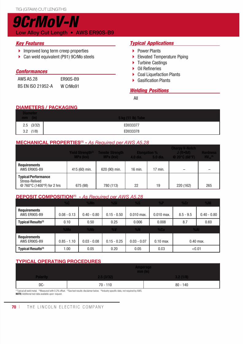
7/18/2019 c110 - Lincoln Electric Consumables 2014
http://slidepdf.com/reader/full/c110-lincoln-electric-consumables-2014 70/51170 ı T H E L I N C O L N E L E C T R I C C O M P A N Y
TIG (GTAW) CUT LENGTHS
9CrMoV-N Low Alloy Cut Length • AWS ER90S-B9
Typical ApplicationsKey Features
Welding Positions
Conformances
Improved long term creep properties
Can weld equivalent (P91) 9CrMo steels
Power Plants
Elevated Temperature Piping Turbine Castings
Oil Refineries
Coal Liquefaction Plants
Gasification Plants
All
AWS A5.28
BS EN ISO 21952-A
ER90S-B9
W CrMo91
DIAMETERS / PACKAGINGDiameter
5 kg (11 lb) Tubemm (in)
2.5
3.2
(3/32)
(1/8)
ED033377
ED033378
DEPOSIT COMPOSITION(1) - As Required per AWS A5.28
%C %Mn %Si %S %P %Cr %Ni
Requirements AWS ER90S-B9 0.08 - 0.13 0.40 - 0.80 0.15 - 0.50 0.010 max. 0.010 max. 8.5 - 9.5 0.40 - 0.80
Typical Results(3) 0.10 0.50 0.25 0.006 0.008 8.7 0.60
%Mo %Nb %V %N %Cu %Al
Requirements AWS ER90S-B9 0.85 - 1.10 0.03 - 0.08 0.15 - 0.25 0.03 - 0.07 0.10 max. 0.40 max.
Typical Results(3) 1.00 0.05 0.20 0.05 0.03 <0.01
MECHANICAL PROPERTIES(1) - As Required per AWS A5.28
Yield Strength(2)
MPa (ksi)
Tensile Strength
MPa (ksi)
Elongation %
Charpy V-NotchJ (ft•lbf) Hardness
HV10(4)4.0 dia. 5.0 dia. @ 20°C (68°F)
Requirements AWS ER90S-B9 415 (60) min. 620 (90) min. 16 min. 17 min. – –
Typical PerformanceStress-Relived@ 760°C (1400°F) for 2 hrs 675 (98)
780 (113)
22
19
220 (162)
265
(1)Typical all weld metal. (2)Measured with 0.2% offset. (3)See test results disclaimer below. (4)Industry specific data, not required by AWS.
NOTE: Additional test data available upon request.
TYPICAL OPERATING PROCEDURES
Polarity
Amperagemm (in)
2.5 (3/32) 3.2 (1/8)
DC- 70 - 110 80 - 140

7/18/2019 c110 - Lincoln Electric Consumables 2014
http://slidepdf.com/reader/full/c110-lincoln-electric-consumables-2014 71/511W E L D I N G C O N S U M A B L E S ı 71
CONSUMABLES
Mild SteelMetalshield® MC-6® ......................................... 72Metalshield® MC®-706 ..................................... 74
Metalshield®
MC-710XL®
................................. 76Low AlloyMetalshield® MC®-80Ni1..................................78Metalshield® MC®-90 ....................................... 80Metalshield® MC®-110 ..................................... 82
METAL-CORED
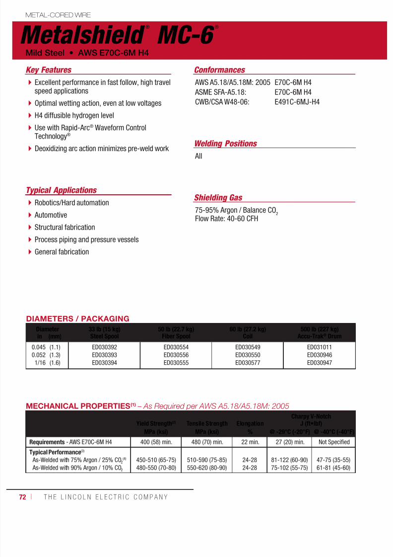
7/18/2019 c110 - Lincoln Electric Consumables 2014
http://slidepdf.com/reader/full/c110-lincoln-electric-consumables-2014 72/51172 ı T H E L I N C O L N E L E C T R I C C O M P A N Y
Metalshield ®
MC-6 ®
METAL-CORED WIRE
Welding Positions
Typical Applications
All
Robotics/Hard automation
Automotive
Structural fabrication
Process piping and pressure vessels
General fabrication
Excellent performance in fast follow, high travelspeed applications
Optimal wetting action, even at low voltages
H4 diffusible hydrogen level
Use with Rapid-Arc® Waveform ControlTechnology®
Deoxidizing arc action minimizes pre-weld work
Conformances
Shielding Gas
75-95% Argon / Balance CO2
Flow Rate: 40-60 CFH
Key Features
AWS A5.18/A5.18M: 2005
ASME SFA-A5.18:CWB/CSA W48-06:
E70C-6M H4
E70C-6M H4E491C-6MJ-H4
DIAMETERS / PACKAGING
Diameter 33 lb (15 kg)Steel Spool
50 lb (22.7 kg)Fiber Spool
60 lb (27.2 kg)Coil
500 lb (227 kg)Accu-Trak® Drumin (mm)
0.045
0.052
1/16
(1.1)
(1.3)
(1.6)
ED030392
ED030393
ED030394
ED030554
ED030556
ED030555
ED030549
ED030550
ED030577
ED031011
ED030946
ED030947
Mild Steel • AWS E70C-6M H4
MECHANICAL PROPERTIES(1) – As Required per AWS A5.18/A5.18M: 2005
Yield Strength(2) Tensile Strength ElongationCharpy V-Notch
J (ft•lbf)MPa (ksi) MPa (ksi) % @ -29°C (-20°F) @ -40°C (-40°F)
Requirements - AWS E70C-6M H4 400 (58) min. 480 (70) min. 22 min. 27 (20) min. Not Specified
Typical Performance(3)
As-Welded with 75% Argon / 25% CO2(4)
As-Welded with 90% Argon / 10% CO2
450-510 (65-75)
480-550 (70-80)
510-590 (75-85)
550-620 (80-90)
24-28
24-28
81-122 (60-90)
75-102 (55-75)
47-75 (35-55)
61-81 (45-60)
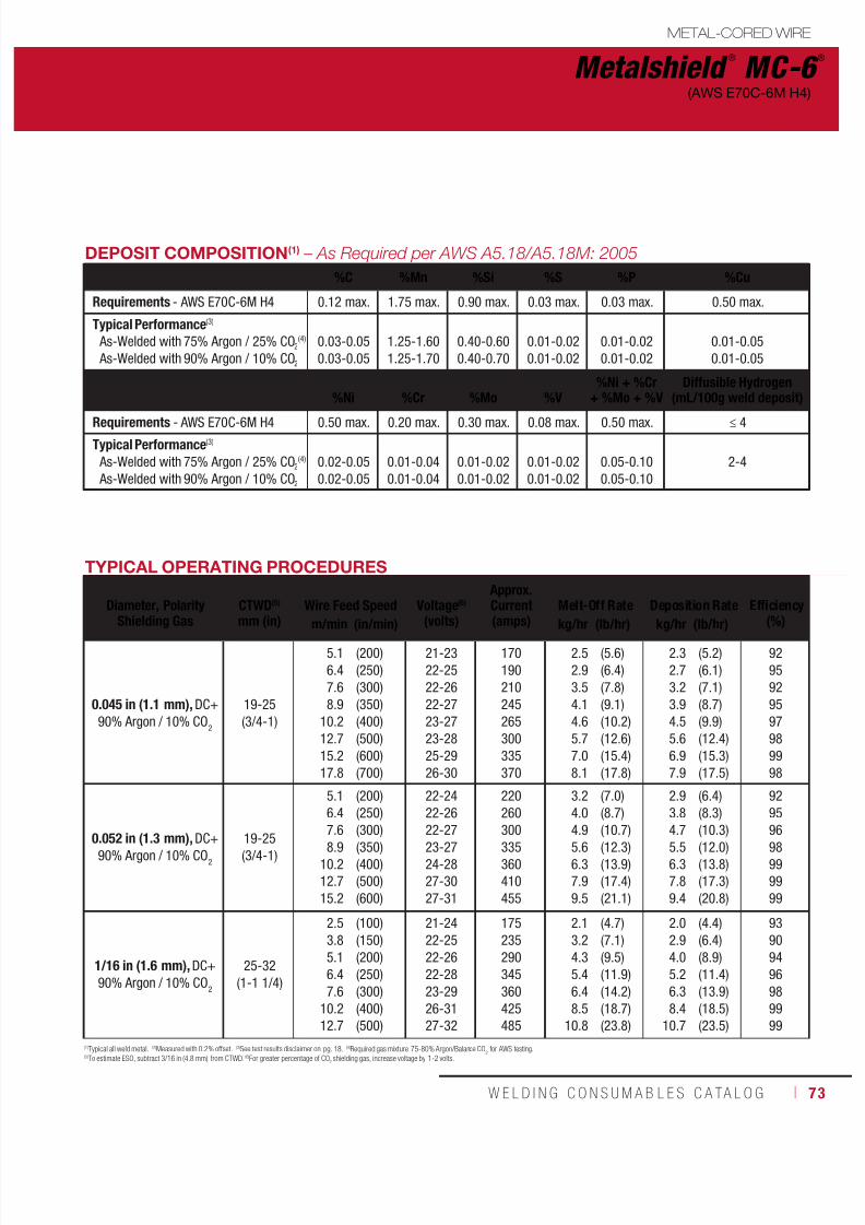
7/18/2019 c110 - Lincoln Electric Consumables 2014
http://slidepdf.com/reader/full/c110-lincoln-electric-consumables-2014 73/511W E L D I N G C O N S U M A B L E S C A TA L O G ı 73
Metalshield ®
MC-6 ®
METAL-CORED WIRE
(AWS E70C-6M H4)
DEPOSIT COMPOSITION(1) – As Required per AWS A5.18/A5.18M: 2005
%C %Mn %Si %S %P %Cu
Requirements - AWS E70C-6M H4 0.12 max. 1.75 max. 0.90 max. 0.03 max. 0.03 max. 0.50 max.
Typical Performance(3)
As-Welded with 75% Argon / 25% CO2(4)
As-Welded with 90% Argon / 10% CO2
0.03-0.05
0.03-0.05
1.25-1.60
1.25-1.70
0.40-0.60
0.40-0.70
0.01-0.02
0.01-0.02
0.01-0.02
0.01-0.02
0.01-0.05
0.01-0.05
%Ni %Cr %Mo %V%Ni + %Cr
+ %Mo + %VDiffusible Hydrogen
(mL/100g weld deposit)
Requirements - AWS E70C-6M H4 0.50 max. 0.20 max. 0.30 max. 0.08 max. 0.50 max. ≤ 4
Typical Performance(3)
As-Welded with 75% Argon / 25% CO2(4)
As-Welded with 90% Argon / 10% CO2
0.02-0.05
0.02-0.05
0.01-0.04
0.01-0.04
0.01-0.02
0.01-0.02
0.01-0.02
0.01-0.02
0.05-0.10
0.05-0.10
2-4
(1)Typical all weld metal. (2)Measured with 0.2% offset. (3)See test results disclaimer on pg. 18. (4)Required gas mixture 75-80% Argon/Balance CO2 for AWS testing.(5)To estimate ESO, subtract 3/16 in (4.8 mm) from CTWD. (6)For greater percentage of CO
2 shielding gas, increase voltage by 1-2 volts.
TYPICAL OPERATING PROCEDURES
Diameter, PolarityShielding Gas
CTWD(5)
mm (in)Wire Feed Speed Voltage(6)
(volts)
Approx.Current(amps)
Melt-Off Rate Deposition Rate Efficiency(%)
m/min (in/min) kg/hr (lb/hr) kg/hr (lb/hr)
0.045 in (1.1 mm), DC+
90% Argon / 10% CO2
19-25
(3/4-1)
5.1
6.4
7.6
8.9
10.2
12.7
15.2
17.8
(200)
(250)
(300)
(350)
(400)
(500)
(600)
(700)
21-23
22-25
22-26
22-27
23-27
23-28
25-29
26-30
170
190
210
245
265
300
335
370
2.5
2.9
3.5
4.1
4.6
5.7
7.0
8.1
(5.6)
(6.4)
(7.8)
(9.1)
(10.2)
(12.6)
(15.4)
(17.8)
2.3
2.7
3.2
3.9
4.5
5.6
6.9
7.9
(5.2)
(6.1)
(7.1)
(8.7)
(9.9)
(12.4)
(15.3)
(17.5)
92
95
92
95
97
98
99
98
0.052 in (1.3 mm), DC+90% Argon / 10% CO
2
19-25(3/4-1)
5.1
6.4
7.6
8.9
10.2
12.7
15.2
(200)
(250)
(300)
(350)
(400)
(500)
(600)
22-24
22-26
22-27
23-27
24-28
27-30
27-31
220
260
300
335
360
410
455
3.2
4.0
4.9
5.6
6.3
7.9
9.5
(7.0)
(8.7)
(10.7)
(12.3)
(13.9)
(17.4)
(21.1)
2.9
3.8
4.7
5.5
6.3
7.8
9.4
(6.4)
(8.3)
(10.3)
(12.0)
(13.8)
(17.3)
(20.8)
92
95
96
98
99
99
99
1/16 in (1.6 mm), DC+
90% Argon / 10% CO2
25-32
(1-1 1/4)
2.5
3.8
5.1
6.4
7.6
10.2
12.7
(100)
(150)
(200)
(250)
(300)
(400)
(500)
21-24
22-25
22-26
22-28
23-29
26-31
27-32
175
235
290
345
360
425
485
2.1
3.2
4.3
5.4
6.4
8.5
10.8
(4.7)
(7.1)
(9.5)
(11.9)
(14.2)
(18.7)
(23.8)
2.0
2.9
4.0
5.2
6.3
8.4
10.7
(4.4)
(6.4)
(8.9)
(11.4)
(13.9)
(18.5)
(23.5)
93
90
94
96
98
99
99

7/18/2019 c110 - Lincoln Electric Consumables 2014
http://slidepdf.com/reader/full/c110-lincoln-electric-consumables-2014 74/51174 ı T H E L I N C O L N E L E C T R I C C O M P A N Y
Metalshield ®
MC ®
-706 METAL-CORED WIRE
Welding Positions Typical Applications
Flat & HorizontalRobotics/hard automation
Structural fabrication
Process piping and pressure vessels
Shipbuilding
Heavy fabrication
High deposition rates and travel speed
Enhanced silicon island management H4 diffusible hydrogen level
Tolerates high amounts of surface contaminants
Superior arc wetting and bead appearance
Conformances
Shielding Gas
75-95% Argon / Balance CO2
Flow Rate: 40-60 CFH
Key Features
AWS A5.18/A5.18M: 2005
ASME SFA-A5.18: ABS:
CWB/CSA W48-06:
AWS D1.8
FEMA 353
E70C-6M H4
E70C-6M H4E70C-6M H4
E492C-6MJ-H4
DIAMETERS / PACKAGING
Diameter 33 lb (15 kg)Steel Spool
50 lb (22.7 kg)Fiber Spool
50 lb (22.7 kg)Coil
500 lb (227 kg)Accu-Trak® Drumin (mm)
0.045
0.052
1/16
(1.1)
(1.3)
(1.6)
ED031583
ED031584
ED031585
ED031586
ED031587
ED031588
ED031589
ED031590
ED031591
ED031592
ED031593
ED031594
Mild Steel • AWS E70C-6M H4
MECHANICAL PROPERTIES(1) – As Required per AWS A5.18/A5.18M: 2005
Yield Strength(2) Tensile Strength ElongationCharpy V-Notch
J (ft•lbf)
MPa (ksi) MPa (ksi) % @ -29°C (-20°F) @ -40°C (-40°F)
Requirements - AWS E70C-6M H4 400 (58) min. 480 (70) min. 22 min. 27 (20) min. Not Specified
Typical Results(3)
As-Welded with 75% Argon / 25% CO2(4)
As-Welded with 90% Argon / 10% CO2
450-510 (65-75)
480-550 (70-80)
510-590 (75-85)
550-620 (80-90)
24-28
24-28
96-137 (71-101)
57-108 (42-80)
81-111 (60-82)
41-94 (30-69)
uctural Welding Code
smic Supplement

7/18/2019 c110 - Lincoln Electric Consumables 2014
http://slidepdf.com/reader/full/c110-lincoln-electric-consumables-2014 75/511W E L D I N G C O N S U M A B L E S C A TA L O G ı 75
Metalshield ®
MC ®
-706
METAL-CORED WIRE
(AWS E70C-6M H4)
DEPOSIT COMPOSITION(1)
– As Required per AWS A5.18/A5.18M: 2005%C %Mn %Si %S %P %Cu
Requirements - AWS E70C-6M H4 0.12 max. 1.75 max. 0.90 max. 0.03 max. 0.03 max. 0.50 max.
Typical Results(3)
As-Welded with 75% Argon / 25% CO2(4)
As-Welded with 90% Argon / 10% CO2
0.03-0.05
0.03-0.05
1.25-1.60
1.25-1.70
0.50-0.80
0.60-0.85
0.02-0.03
0.02-0.03
0.01-0.02
0.01-0.02
0.01-0.05
0.01-0.05
%Ni %Cr %Mo %V%Ni + %Cr
+ %Mo + %VDiffusible Hydrogen
(mL/100g weld deposit)
Requirements - AWS E70C-6M H4 0.50 max. 0.20 max. 0.30 max. 0.08 max. 0.50 max. ≤ 4
Typical Results(3)
As-Welded with 75% Argon / 25% CO2
(3)
As-Welded with 90% Argon / 10% CO2
0.01-0.03
0.01-0.03
0.01-0.04
0.01-0.05
0.01-0.02
0.01-0.02
0.01-0.02
0.01-0.02
0.05-0.10
0.05-0.10
2-4
TYPICAL OPERATING PROCEDURES
Diameter, PolarityShielding Gas
CTWD(5)
mm (in)Wire Feed Speed Voltage(6)
(volts)
Approx.Current(amps)
Melt-Off Rate Deposition Rate Efficiency(%)m/min (in/min) kg/hr (lb/hr) kg/hr (lb/hr)
0.045 in (1.1 mm), DC+
90% Argon / 10% CO2
19-25
(3/4-1)
5.1
6.4
7.68.9
10.2
11.4
12.7
14.0
15.2
16.5
17.8
(200)
(250)
(300)(350)
(400)
(450)
(500)
(550)
(600)
(650)
(700)
21-23
22-24
22-2622-27
23-27
23-28
23-29
24-29
25-30
26-30
26-30
155
185
220245
260
280
305
315
325
355
360
2.3
2.8
3.54.0
4.6
5.2
5.7
6.3
6.8
7.5
8.0
(5.0)
(6.2)
(7.7)(8.9)
(10.1)
(11.4)
(12.6)
(13.9)
(15.1)
(16.5)
(17.7)
2.1
2.6
3.23.7
4.3
4.9
5.5
6.2
6.7
7.4
7.9
((4.6)
(5.8)
(7.0)(8.2)
(9.4)
(10.7)
(12.2)
(13.6)
(14.8)
(16.3)
(17.5)
92
94
9193
93
94
97
98
98
98
99
0.052 in (1.3 mm), DC+90% Argon / 10% CO
2
19-25(3/4-1)
5.1
6.4
7.6
8.910.2
11.4
12.7
14.0
(200)
(250)
(300)
(350)(400)
(450)
(500)
(550)
22-24
22-26
22-27
23-2724-28
25-28
27-29
27-30
210
260
290
315350
370
390
420
3.0
3.9
4.6
5.46.3
6.9
7.7
8.4
(6.7)
(8.5)
(10.2)
(11.8)(13.8)
(15.2)
(16.9)
(18.5)
2.9
3.5
4.3
5.26.1
6.8
7.6
8.3
(6.3)
(7.8)
(9.5)
(11.4)(13.4)
(15.1)
(16.8)
(18.3)
94
92
94
9797
99
99
99
1/16 in (1.6 mm), DC+
90% Argon / 10% CO2
25-32
(1-1 1/4)
3.8
5.1
6.4
7.6
8.9
10.2
11.4
(150)
(200)
(250)
(300)
(350)
(400)
(450)
22-24
22-25
23-28
24-29
26-30
26-31
27-31
230
280
310
370
400
450
480
3.2
4.3
5.3
6.3
7.4
8.3
9.5
(7.0)
(9.4)
(11.6)
(13.9)
(16.3)
(18.4)
(21.0)
2.8
3.9
5.0
6.3
7.2
8.3
9.3
(6.2)
(8.7)
(11.0)
(13.8)
(15.9)
(18.4)
(20.6)
89
93
94
99
98
99
98
(1)Typical all weld metal. (2)Measured with 0.2% offset. (3)See test results disclaimer on pg. 18. (4)Required gas mixture 75-80% Argon/Balance CO2 for AWS testing. (5)To estimate ESO, subtract 3/16 in (4.8 mm) from CTWD. (6)For greater percentage of CO2 shield-ing gas, increase voltage by 1-2 volts. NOTE: This product contains micro-alloying elements. Additional information available upon request.
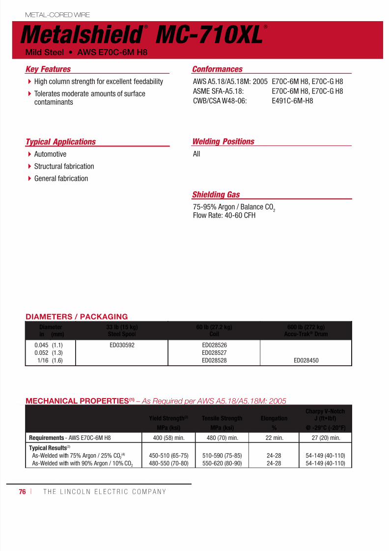
7/18/2019 c110 - Lincoln Electric Consumables 2014
http://slidepdf.com/reader/full/c110-lincoln-electric-consumables-2014 76/51176 ı T H E L I N C O L N E L E C T R I C C O M P A N Y
Metalshield ®
MC-710XL ®
METAL-CORED WIRE
Welding Positions Typical Applications
All Automotive
Structural fabrication
General fabrication
High column strength for excellent feedability
Tolerates moderate amounts of surfacecontaminants
Conformances
Shielding Gas
75-95% Argon / Balance CO2
Flow Rate: 40-60 CFH
Key Features
AWS A5.18/A5.18M: 2005
ASME SFA-A5.18:CWB/CSA W48-06:
E70C-6M H8, E70C-G H8
E70C-6M H8, E70C-G H8E491C-6M-H8
DIAMETERS / PACKAGING
Diameter 33 lb (15 kg)Steel Spool
60 lb (27.2 kg)Coil
600 lb (272 kg)Accu-Trak® Drumin (mm)
0.045
0.052
1/16
(1.1)
(1.3)
(1.6)
ED030592 ED028526
ED028527
ED028528 ED028450
MECHANICAL PROPERTIES(1) – As Required per AWS A5.18/A5.18M: 2005
Yield Strength(2) Tensile Strength ElongationCharpy V-Notch
J (ft•lbf)
MPa (ksi) MPa (ksi) % @ -29°C (-20°F)
Requirements - AWS E70C-6M H8 400 (58) min. 480 (70) min. 22 min. 27 (20) min.
Typical Results(3)
As-Welded with 75% Argon / 25% CO2(4)
As-Welded with with 90% Argon / 10% CO2
450-510 (65-75)
480-550 (70-80)
510-590 (75-85)
550-620 (80-90)
24-28
24-28
54-149 (40-110)
54-149 (40-110)
Mild Steel • AWS E70C-6M H8

7/18/2019 c110 - Lincoln Electric Consumables 2014
http://slidepdf.com/reader/full/c110-lincoln-electric-consumables-2014 77/511W E L D I N G C O N S U M A B L E S C A TA L O G ı 77
Metalshield ®
MC-710XL ®
METAL-CORED WIRE
(AWS E70C-6M H8)
TYPICAL OPERATING PROCEDURES
Diameter, PolarityShielding Gas
CTWD(5)
mm (in)Wire Feed Speed Voltage(6)
(volts)
Approx.Current(amps)
Melt-Off Rate Deposition Rate Efficiency(%)m/min (in/min) kg/hr (lb/hr) kg/hr (lb/hr)
0.045 in (1.1 mm), DC+
90% Argon / 10% CO2
19-25
(3/4-1)
5.1
6.4
8.9
11.4
14.016.5
(200)
(250)
(350)
(450)
(550)(650)
24-25
25-26
28-29
30-31
32-3335-36
165
200
230
310
355385
2.3
2.9
4.1
5.2
6.47.6
(5.1)
(6.4)
(9.0)
(11.5)
(14.1)(16.7)
2.2
2.8
3.9
5.0
6.27.4
(4.8)
(6.1)
(8.6)
(11.1)
(13.7)(16.2)
94
95
95
96
9797
0.052 in (1.3 mm), DC+
90% Argon / 10% CO2
25-32
(1-1 1/4)
4.4
6.4
8.9
11.4
14.0
(175)
(250)
(350)
(450)
(550)
23-25
25-27
28-30
31-33
34-36
195
260
330
390
430
2.7
3.9
5.4
7.0
8.5
(6.0)
(8.6)
(11.9)
(15.4)
(18.8)
2.5
3.6
5.1
6.6
8.1
(5.5)
(8.0)
(11.2)
(14.5)
(17.8)
92
93
94
94
95
1/16 in (1.6 mm), DC+
90% Argon / 10% CO2
25-32
(1-1 1/4)
3.8
6.4
8.9
11.4
(150)
(250)
(350)
(450)
24-26
28-30
33-35
35-37
235
330
410
460
3.1
5.2
7.4
9.4
(6.9)
(11.4)
(16.3)
(20.7)
2.9
4.9
7.0
9.0
(6.5)
(10.8)
(15.5)
(19.8)
94
95
95
96
(1)Typical all weld metal. (2)Measured with 0.2% offset. (3)See test results disclaimer on pg. 18. (4)Required gas mixture 75-80% Argon/Balance CO2 for AWS testing.(5)To estimate ESO, subtract 3/16 in (4.8 mm) from CTWD. (6)For greater percentage of CO
2 shielding gas, increase voltage by 1-2 volts.
DEPOSIT COMPOSITION(1) – As Required per AWS A5.18/A5.18M: 2005
%C %Mn %Si %S
Requirements - AWS E70C-6M H8 0.12 max. 1.75 max. 0.90 max. 0.03 max.
Typical Results(3)
As-Welded with 75% Argon / 25% CO2(4)
As-Welded with 90% Argon / 10% CO2
0.02-0.05
0.02-0.05
1.20-1.65
1.40-1.85
0.50-0.75
0.50-0.90
0.01-0.02
0.01-0.02
%P %Cu %Ni %Cr
Requirements - AWS E70C-6M H8 0.03 max. 0.50 max. 0.50 max. 0.20 max.
Typical Results(3)
As-Welded with 75% Argon / 25% CO2(4)
As-Welded with 90% Argon / 10% CO2
0.01-0.02
0.01-0.02
0.01-0.05
0.01-0.05
0.02-0.04
0.02-0.05
0.01-0.04
0.01-0.04
%Mo %V%Ni + %C
+ %Mo + %VDiffusible Hydrogen
(mL/100g weld deposit)
Requirements - AWS E70C-6M H8 0.30 max. 0.08 max. 0.50 max. ≤ 8
Typical Results(3)
As-Welded with 75% Argon / 25% CO2(4)
As-Welded with 90% Argon / 10% CO2
0.01-0.02
0.01-0.02
0.01-0.02
0.01-0.02
0.05-0.10
0.05-0.10
6-8

7/18/2019 c110 - Lincoln Electric Consumables 2014
http://slidepdf.com/reader/full/c110-lincoln-electric-consumables-2014 78/51178 ı T H E L I N C O L N E L E C T R I C C O M P A N Y
Metalshield ®
MC ®
-80Ni1METAL-CORED WIRE
Welding Positions
Typical Applications
All
Robotics/hard automation
Weathering grades of the appropriate strength ASTM A588 & A709 steels
Structural fabrication Heavy fabrication
H4 diffusible hydrogen levels
Low spatter and excellent arc stability Deoxidizing agents minimize pre- andpost-weld clean up
Enhanced silicon island management
Low temperature impact properties – Capableof exceeding 40 J (29 ft•lbf) @ -45°C (-50°F)
Excellent bead shape and profile
Meets the AWS E80C-Ni1 H4 requirement fortensile and yield strength in both the as-welded
condition and after 2 hrs of post-weld heattreating (PWHT)
Conformances
Shielding Gas
75-95% Argon / Balance CO2
95-99% Argon / Balance O2
Flow Rate: 40-60 CFH
Key Features
AWS A5.28/A5.28M: 2005 ASME SFA-5.28CWB / CSA W48-06
E80C-Ni1 H4E80C-Ni1 H4E55C-Ni1 H4 (E80C-Ni1 H4)
Low Alloy • AWS E80C-Ni1
DIAMETERS / PACKAGING
Diameter 33 lb. (15 kg) Plastic Spool(Vacuum Sealed Foil Bag)
500 lb. (227 kg)Accu-Trak® Drumin. (mm)
0.045
0.052
1/16
(1.1)
(1.3)
(1.6)
ED034213
ED034214
ED034215
ED034216
ED034217
ED034218

7/18/2019 c110 - Lincoln Electric Consumables 2014
http://slidepdf.com/reader/full/c110-lincoln-electric-consumables-2014 79/511W E L D I N G C O N S U M A B L E S C A TA L O G ı 79
Metalshield ®
MC ®
-80Ni1
METAL-CORED WIRE
(AWS E80C-Ni1)
(1) Typical all weld metal. (2) Measured with 0.2% offset. (3) See test results disclaimer on pg. 18. (4) To estimate ESO, subtract 1/4 in. (6.0 mm) from CTWD. (5) For shielding gas blends of 95-99% Argon / Balance O(2), decrease voltage by 1-2 volts.
MECHANICAL PROPERTIES(1) – As Required per AWS A5.20/A5.20M: 2005
Yield Strength(2) Tensile Strength ElongationCharpy V-Notch
J (ft•lbf)
MPa (ksi) MPa (ksi) % @ -45°C (-50°F)Requirements - AWS E80C-Ni1 H4 As-Welded with Argon / 1-5% O2 470 (68) min. 550 (80) 24 min. 27 (20) min.
Test Results(3)
As-Welded with 98% Argon / 2% O2 530-620 (77-90) 605-660 (88-96) 24-28 60-100 (43-76)
As-Welded with 92% Argon / 8% CO2 Stress Relieved 2 hrs. @ 621°C (1150°F)
510 - 570 (74 - 83)540 (78)
585 - 635 (85 - 92)620 (90)
27 - 2929
85 - 120 (61 - 89)85 (61)
As-Welded with 75% Argon / 25% CO2 Stress Relieved 2 hrs. @ 621°C (1150°F)
480 - 540 (70 - 78)470 (68)
565 - 615 (82 - 89)565 (82)
28 - 3129
40 - 95 (29 - 70)80 (58)
DEPOSIT COMPOSITION(1) – As Required per AWS A5.20/A5.20M: 2005
%C %Mn %Si %S %PRequirements - AWS E80C-Ni1 H4 As-Welded with Argon / 1-5% O2 0.12 max. 1.50 max. 0.90 max. 0.030 max. 0.025 max.
Test Results(3)
As-Welded with 98% Argon / 2% O2
As-Welded with 92% Argon / 8% CO2
As-Welded with 75% Argon / 25% CO2
0.07 - 0.080.05 - 0.070.05 - 0.06
1.31 - 1.351.22 - 1.301.14 - 1.19
0.48 - 0.500.43 - 0.470.38 - 0.42
0.024 max.0.024 max.0.024 max.
0.0120.0120.012
%Cu %Ni %Mo %VDiffusible Hydrogen
(mL/100g weld deposit)
Requirements - AWS E80C-Ni1 H4 As-Welded with Argon / 1-5% O2 0.35 max. 0.80 - 1.10 0.30 max. 0.03 max. ≤ 4
Test Results(3)
As-Welded with 98% Argon / 2% O2 As-Welded with 92% Argon / 8% CO2
As-Welded with 75% Argon / 25% CO2
0.03 - 0.050.03 - 0.050.04 - 0.06
0.84 - 0.860.83 - 0.860.80 - 0.85
0.10 max.0.10 max.0.10 max.
0.01 max.0.01 max.0.01 max.
3 - 43 - 43 - 4
TYPICAL OPERATING PROCEDURESDiameter, Polarity
Shielding GasCTWD(4)
mm (in)Wire Feed Speed Voltage(5)
(Volts)Approx. Current
(Amps)Melt-Off Rate Deposition Rate Efficiency
(%)m/min (in/min) kg/hr (lb/hr) kg/hr (lb/hr)
0.045 in. (1.1 mm), DC+92% Argon / 8% CO2
19-25(3/4-1)
5.16.47.68.9
10.212.715.2
(200)(250)(300)(350)
(400)(500)(600)
21-2322-2522-2622-27
23-2723-2825-29
180220250280
310350380
2.53.13.74.4
4.96.27.4
(5.5)(6.8)(8.2)(9.6)
(10.9)(13.6)(16.3)
2.22.93.43.9
4.55.66.9
(4.9)(6.3)(7.4)(8.9)
(10.3)(13.0)(15.6)
89939092
949696
0.052 in. (1.3 mm), DC+92% Argon / 8% CO2
25-32(1-1 1/4)
3.85.16.47.6
10.2
(150)(200)(250)(300)(400)
22-2523-2624-2826-2927-30
200250290320360
2.43.24.04.86.4
(5.3)(7.0)(8.8)(10.5)(14.0)
2.23.03.84.76.4
(4.8)(6.6)(8.4)(10.4)(14.0)
9194959999
1/16 in. (1.6 mm), DC+92% Argon / 8% CO2
25-32(1-1 1/4)
3.85.16.47.6
10.2
(150)(200)(250)(300)(400)
22-2523-2624-2826-2927-30
235295350395465
3.44.45.86.99.2
(7.5)(9.7)(12.7)(15.2)(20.2)
3.04.25.46.58.8
(6.7)(9.2)(11.8)(14.3)(19.3)
8995939496

7/18/2019 c110 - Lincoln Electric Consumables 2014
http://slidepdf.com/reader/full/c110-lincoln-electric-consumables-2014 80/51180 ı T H E L I N C O L N E L E C T R I C C O M P A N Y
Metalshield ®
MC ®
-90 METAL-CORED WIRE
Welding Positions
Typical Applications
All
Robotics/hard automation
HSLA steels (i.e. ASTM A678 & A710)
Crane fabrication
Structural fabrication
Heavy fabrication
Power generation
H4 diffusible hydrogen levels
Low spatter and excellent arc stability Deoxidizing agents minimize pre- andpost-weld clean up
Enhanced silicon island management
Low temperature impact properties –Charpy V-Notch test results capable ofexceeding 40 J (30 ft•lbf) @ -51°C (-60°F)
Excellent bead shape and profile
Conformances
Shielding Gas
75-90% Argon / Balance CO2
Flow Rate: 40-60 CFH
Key Features
AWS A5.28/A5.28M: 2005:
ASME SFA-A5.28:CWB / CSA W48-06:
E90C-K3 H4
E90C-K3 H4E62C-K3 H4 (E90C-K3 H4)
Low Alloy • AWS E90C-K3 H4
DIAMETERS / PACKAGINGDiameter 33 lb. (15 kg)
Plastic Spool500 lb. (227 kg)
Accu-Trak® Drumin (mm)
0.045
0.052
1/16
(1.1)
(1.3)
(1.6)
ED033904
ED033905
ED033906
ED033907
ED033908
ED033909
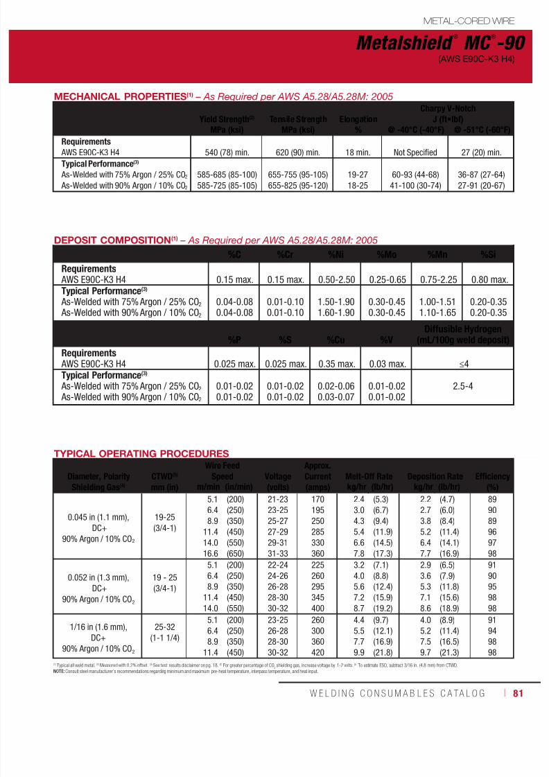
7/18/2019 c110 - Lincoln Electric Consumables 2014
http://slidepdf.com/reader/full/c110-lincoln-electric-consumables-2014 81/511W E L D I N G C O N S U M A B L E S C A TA L O G ı 81
Metalshield ®
MC ®
-90
METAL-CORED WIRE
(AWS E90C-K3 H4)
TYPICAL OPERATING PROCEDURES
Diameter, PolarityShielding Gas(4)
CTWD(5)
mm (in)
Wire FeedSpeed
Voltage(volts)
Approx.Current(amps)
Melt-Off Rate
Deposition Rate
Efficiency
(%)m/min (in/min) kg/hr (lb/hr) kg/hr (lb/hr)
0.045 in (1.1 mm),
DC+90% Argon / 10% CO2
19-25
(3/4-1)
5.1
6.4
8.9
11.414.0
16.6
(200)
(250)
(350)
(450)(550)
(650)
21-23
23-25
25-27
27-2929-31
31-33
170
195
250
285330
360
2.4
3.0
4.3
5.46.6
7.8
(5.3)
(6.7)
(9.4)
(11.9)(14.5)
(17.3)
2.2
2.7
3.8
5.26.4
7.7
(4.7)
(6.0)
(8.4)
(11.4)(14.1)
(16.9)
89
90
89
9697
98
0.052 in (1.3 mm),
DC+
90% Argon / 10% CO2
19 - 25
(3/4-1)
5.1
6.4
8.9
11.4
14.0
(200)
(250)
(350)
(450)
(550)
22-24
24-26
26-28
28-30
30-32
225
260
295
345
400
3.2
4.0
5.6
7.2
8.7
(7.1)
(8.8)
(12.4)
(15.9)
(19.2)
2.9
3.6
5.3
7.1
8.6
(6.5)
(7.9)
(11.8)
(15.6)
(18.9)
91
90
95
98
98
1/16 in (1.6 mm),
DC+
90% Argon / 10% CO2
25-32
(1-1 1/4)
5.1
6.4
8.9
11.4
(200)
(250)
(350)
(450)
23-25
26-28
28-30
30-32
260
300
360
420
4.4
5.5
7.7
9.9
(9.7)
(12.1)
(16.9)
(21.8)
4.0
5.2
7.5
9.7
(8.9)
(11.4)
(16.5)
(21.3)
91
94
98
98
MECHANICAL PROPERTIES(1) – As Required per AWS A5.28/A5.28M: 2005
Yield Strength(2) Tensile Strength ElongationCharpy V-Notch
J (ft•lbf)
MPa (ksi) MPa (ksi) % @ -40°C (-40°F) @ -51°C (-60°F)Requirements AWS E90C-K3 H4
540 (78) min.
620 (90) min.
18 min.
Not Specified
27 (20) min.
Typical Performance(3)
As-Welded with 75% Argon / 25% CO2
As-Welded with 90% Argon / 10% CO2
585-685 (85-100)
585-725 (85-105)
655-755 (95-105)
655-825 (95-120)
19-27
18-25
60-93 (44-68)
41-100 (30-74)
36-87 (27-64)
27-91 (20-67)
DEPOSIT COMPOSITION(1) – As Required per AWS A5.28/A5.28M: 2005
%C %Cr %Ni %Mo %Mn %Si
Requirements AWS E90C-K3 H4 0.15 max. 0.15 max. 0.50-2.50 0.25-0.65 0.75-2.25 0.80 max.Typical Performance(3)
As-Welded with 75% Argon / 25% CO2
As-Welded with 90% Argon / 10% CO2
0.04-0.080.04-0.08
0.01-0.100.01-0.10
1.50-1.901.60-1.90
0.30-0.450.30-0.45
1.00-1.511.10-1.65
0.20-0.350.20-0.35
%P %S %Cu %VDiffusible Hydrogen
(mL/100g weld deposit)Requirements AWS E90C-K3 H4 0.025 max. 0.025 max. 0.35 max. 0.03 max. ≤4Typical Performance(3)
As-Welded with 75% Argon / 25% CO2
As-Welded with 90% Argon / 10% CO2
0.01-0.02
0.01-0.02
0.01-0.02
0.01-0.02
0.02-0.06
0.03-0.07
0.01-0.02
0.01-0.02
2.5-4
(1) Typical all weld metal. (2) Measured with 0.2% offset. (3) See test results disclaimer on pg. 18. (4) For greater percentage of CO2 shielding gas, increase voltage by 1-2 volts. (5) To estimate ESO, subtract 3/16 in. (4.8 mm) from CTWD.NOTE: Consult steel manufacturer’s recommendations regarding minimum and maximum pre-heat temperature, interpass temperature, and heat input.
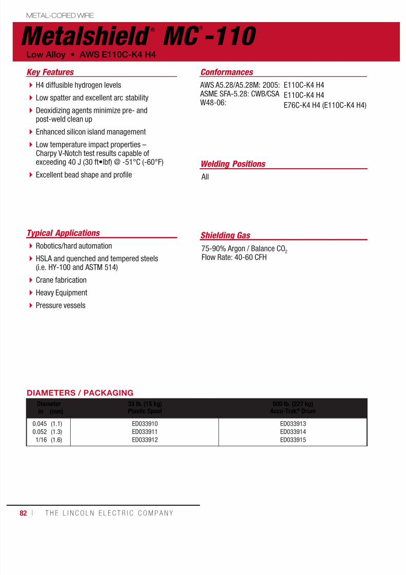
7/18/2019 c110 - Lincoln Electric Consumables 2014
http://slidepdf.com/reader/full/c110-lincoln-electric-consumables-2014 82/51182 ı T H E L I N C O L N E L E C T R I C C O M P A N Y
Metalshield ®
MC ®
-110 METAL-CORED WIRE
Welding Positions
Typical Applications
All
Robotics/hard automation
HSLA and quenched and tempered steels(i.e. HY-100 and ASTM 514)
Crane fabrication
Heavy Equipment Pressure vessels
H4 diffusible hydrogen levels
Low spatter and excellent arc stability Deoxidizing agents minimize pre- andpost-weld clean up
Enhanced silicon island management
Low temperature impact properties –Charpy V-Notch test results capable ofexceeding 40 J (30 ft•lbf) @ -51°C (-60°F)
Excellent bead shape and profile
Conformances
Shielding Gas
75-90% Argon / Balance CO2
Flow Rate: 40-60 CFH
Key Features
AWS A5.28/A5.28M: 2005: ASME SFA-5.28: CWB/CSAW48-06:
E110C-K4 H4
E110C-K4 H4E76C-K4 H4 (E110C-K4 H4)
Low Alloy • AWS E110C-K4 H4
DIAMETERS / PACKAGINGDiameter 33 lb. (15 kg)
Plastic Spool500 lb. (227 kg)
Accu-Trak® Drumin (mm)
0.045
0.052
1/16
(1.1)
(1.3)
(1.6)
ED033910
ED033911
ED033912
ED033913
ED033914
ED033915

7/18/2019 c110 - Lincoln Electric Consumables 2014
http://slidepdf.com/reader/full/c110-lincoln-electric-consumables-2014 83/511W E L D I N G C O N S U M A B L E S C A TA L O G ı 83
Metalshield ®
MC ®
-110
METAL-CORED WIRE
(AWS E110C-K4 H4)
TYPICAL OPERATING PROCEDURES
Diameter, PolarityShielding Gas(4)
CTWD(5)
mm (in)
Wire Feed Speed
Voltage(volts)
Approx.Current(amps)
Melt-Off Rate
Deposition Rate
Efficiency
(%)m/min (in/min) kg/hr (lb/hr) kg/hr (lb/hr)
0.045 in (1.1 mm),
DC+90% Argon / 10% CO2
19-25
(3/4-1)
5.1
6.4
8.9
11.414.0
16.6
(200)
(250)
(350)
(450)(550)
(650)
22-24
24-26
26-28
28-3030-32
31-33
170
190
240
290330
370
2.4
3.0
4.2
5.46.5
7.8
(5.3)
(6.7)
(9.2)
(11.8)(14.4)
(17.1)
2.1
2.8
3.8
5.16.3
7.6
(4.7)
(6.1)
(8.4)
(11.3)(13.9)
(16.7)
88
91
91
9597
97
0.052 in (1.3 mm),
DC+
90% Argon / 10% CO2
19-25
(3/4-1)
5.1
6.4
8.9
11.4
14.0
(200)
(250)
(350)
(450)
(550)
23-25
25-27
27-29
29-31
31-33
225
255
295
350
400
3.2
4.0
5.5
7.2
8.7
(7.0)
(8.8)
(12.2)
(15.8)
(19.1)
2.8
3.7
5.3
7.0
8.5
(6.2)
(8.1)
(11.6)
(15.4)
(18.8)
89
92
95
98
98
1/16 in (1.6 mm),
DC+
90% Argon / 10% CO2
25-32
(1-1 1/4)
5.1
6.4
8.9
11.4
(200)
(250)
(350)
(450)
24-26
26-28
28-30
30-32
270
320
385
465
4.4
5.4
7.7
9.8
(9.6)
(12.1)
(16.9)
(21.6)
3.9
5.1
7.4
9.6
(8.6)
(11.3)
(16.4)
(21.2)
89
94
97
98
MECHANICAL PROPERTIES(1) – As Required per AWS A5.28/A5.28M: 2005
Yield Strength(2) Tensile Strength ElongationCharpy V-Notch
J (ft•lbf)
MPa (ksi) MPa (ksi) % @ -40°C (-40°F) @ -51°C (-60°F)Requirements AWS E110C-K4 H4
680 (98) min.
760 (110) min.
15 min.
Not Specified
27 (20) min.
Typical Performance(3)
As-Welded with 75% Argon / 25% CO2
As-Welded with 90% Argon / 10% CO2
690-795 (100-115)
725-825 (105-120)
760-825 (110-120)
790-895 (115-130)
20-24
18-23
60-88 (44-65)
66-95 (48-70)
45-80 (34-59)
59-82 (44-61)
DEPOSIT COMPOSITION(1) – As Required per AWS A5.28/A5.28M: 2005
%C %Cr %Ni %Mo %Mn %Si
Requirements AWS E110C-K4 H4 0.15 max. 0.15-0.65 0.50-2.50 0.25-0.65 0.75-2.25 0.80 max.
Typical Performance(3)
As-Welded with 75% Argon / 25% CO2
As-Welded with 90% Argon / 10% CO2
0.05-0.08
0.05-0.08
0.20-0.35
0.20-0.35
2.00-2.20
2.00-2.20
0.45-0.55
0.45-0.55
1.45-1.75
1.45-1.75
0.45-0.65
0.45-0.65
%P %S %Cu %VDiffusible Hydrogen
(mL/100g weld deposit)Requirements AWS E110C-K4 H4 0.025 max. 0.025 max. 0.35 max. 0.03 max. ≤4
Typical Performance(3)
As-Welded with 75% Argon / 25% CO2
As-Welded with 90% Argon / 10% CO2
0.01-0.02
0.01-0.02
0.01-0.02
0.01-0.02
0.02-0.06
0.02-0.06
0.01-0.02
0.01-0.02
2.5-4
(1) Typical all weld metal. (2) Measured with 0.2% offset. (3) See test results disclaimer on pg. 18. (4) For greater percentage of CO2 shielding gas, increase voltage by 1-2 volts. (5) To estimate ESO, subtract 3/16 in. (4.8 mm) from CTWD.NOTE: Consult steel manufacturer’s recommendations regarding minimum and maximum pre-heat temperature, interpass temperature, and heat input.
7/18/2019 c110 - Lincoln Electric Consumables 2014
http://slidepdf.com/reader/full/c110-lincoln-electric-consumables-2014 84/51184 ı T H E L I N C O L N E L E C T R I C C O M P A N Y
Notes METAL-CORED CONSUMABLES

7/18/2019 c110 - Lincoln Electric Consumables 2014
http://slidepdf.com/reader/full/c110-lincoln-electric-consumables-2014 85/511W E L D I N G C O N S U M A B L E S ı 85
FCAW-S & FCAW-G CONSUMABLES
Self-Shielded (FCAW-S) WireMild Steel, Flat and HorizontalInnershield® NR®-5 ................................86
Innershield® NS-3M ...............................87Innershield® NR®-305 ............................88Innershield® NR®-311 ............................89Innershield® NR®-131 ............................90
Mild Steel, All PositionInnershield® NR®-152 ............................91Innershield® NR®-211-MP ......................92Innershield® NR®-203MP .......................94Innershield® NR®-232 ............................96Innershield® NR®-233 ............................98
Low Alloy, Flat and HorizontalInnershield® NR®-311 Ni ......................100Innershield® NR®-FAB-70 .....................102
Low Alloy, All PositionInnershield® NR®-203 Nickel (1%) ........103Innershield® NR®-212 ..........................104Innershield® NR®-203 Ni C Plus-H ........106Innershield® NR®-440Ni2 .....................107Innershield® NR®-207 ..........................108
Innershield® NR®-208-H .......................109
Gas-Shielded (FCAW-G) WireMild Steel, All PositionUltraCore® 71A85 .................................110
UltraCore® HD-M ..................................112UltraCore® 71C .....................................114UltraCore® HD-C ...................................116UltraCore® 71A75 Dual .........................118UltraCore® 712C ...................................120UltraCore® HD-12C ...............................122UltraCore® 712A80 ...............................124UltraCore® HD-12M ..............................126UltraCore® 712A80-H ...........................128UltraCore® SR-12 .................................130
UltraCore®
SR-12C ...............................132UltraCore® SR-12M ..............................134Outershield® 71 Elite ............................136Outershield® 71 Supreme .....................138Outershield® 71M .................................140
Mild Steel, Flat and HorizontalUltraCore® 70C .....................................142UltraCore® 75C .....................................144Outershield® 70 ....................................146Outershield® XLH-70 ............................148
Low Alloy, All PositionUltraCore® 81Ni1A75-H ........................150UltraCore® 81Ni1C-H ............................152UltraCore® 81Ni2A75-H ........................154UltraCore® 81Ni2C-H ............................156UltraCore® 81K2A75-H .........................158UltraCore® 81K2C-H .............................160Outershield® 91K2-H ............................162Pipeliner® G90M ...................................164Cormet® 1 ............................................165
Cormet® 2 ............................................166Supercore® F91 ....................................167
FLUX-CORED
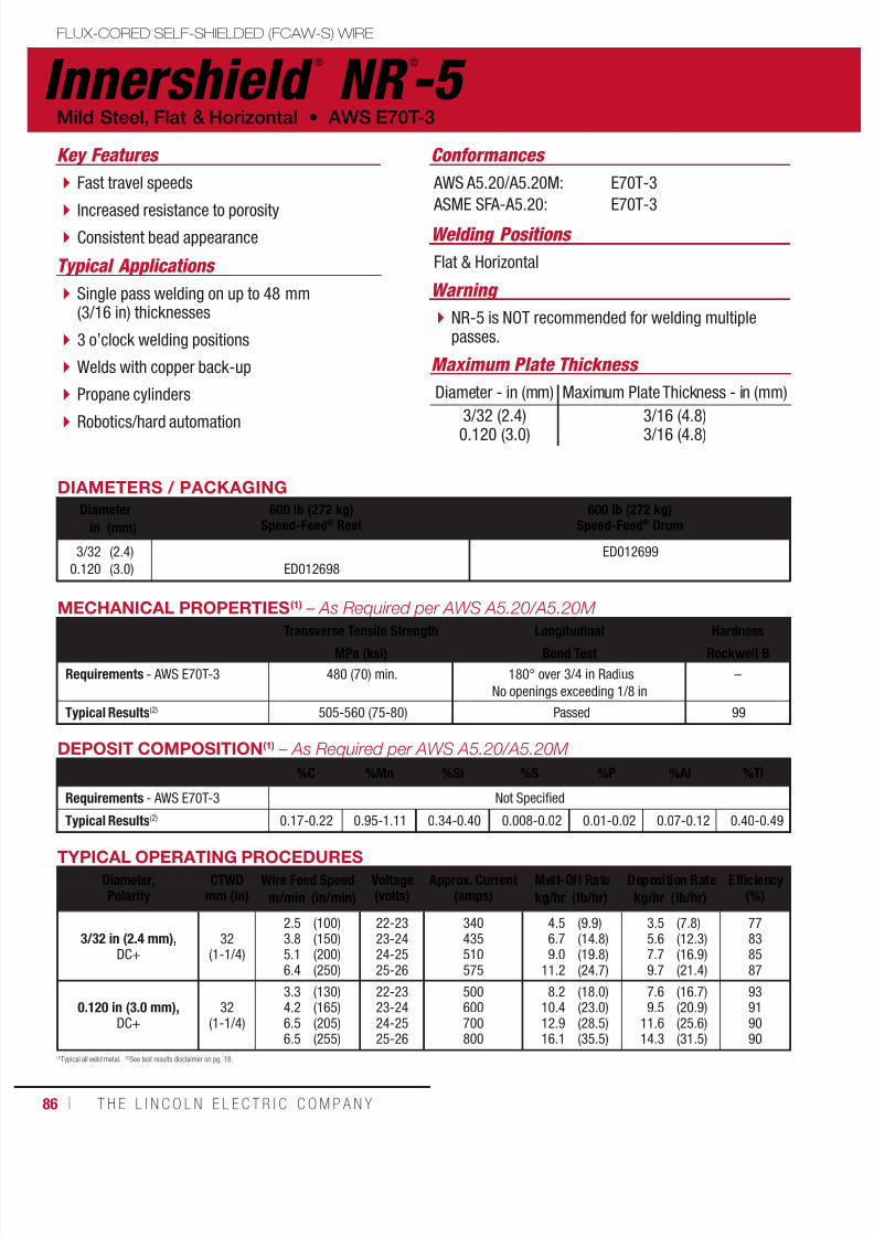
7/18/2019 c110 - Lincoln Electric Consumables 2014
http://slidepdf.com/reader/full/c110-lincoln-electric-consumables-2014 86/51186 ı T H E L I N C O L N E L E C T R I C C O M P A N Y
Innershield ®
NR ®
-5 FLUX-CORED SELF-SHIELDED (FCAW-S) WIRE
Welding Positions
Typical Applications Flat & Horizontal
Single pass welding on up to 48 mm(3/16 in) thicknesses
3 o’clock welding positions
Welds with copper back-up
Propane cylinders
Robotics/hard automation
Fast travel speeds
Increased resistance to porosity Consistent bead appearance
Conformances
Mild Steel, Flat & Horizontal • AWS E70T-3
Key Features
AWS A5.20/A5.20M:
ASME SFA-A5.20:
E70T-3
E70T-3
Warning
NR-5 is NOT recommended for welding multiplepasses.
Maximum Plate Thickness
Diameter - in (mm) Maximum Plate Thickness - in (mm)
3/32 (2.4)0.120 (3.0) 3/16 (4.8)3/16 (4.8)
DIAMETERS / PACKAGING
Diameter 600 lb (272 kg)Speed-Feed® Reel
600 lb (272 kg)Speed-Feed® Drumin (mm)
3/320.120
(2.4)(3.0) ED012698
ED012699
DEPOSIT COMPOSITION(1) – As Required per AWS A5.20/A5.20M
%C %Mn %Si %S %P %Al %Ti
Requirements - AWS E70T-3 Not Specified
Typical Results(2) 0.17-0.22 0.95-1.11 0.34-0.40 0.008-0.02 0.01-0.02 0.07-0.12 0.40-0.49
MECHANICAL PROPERTIES(1) – As Required per AWS A5.20/A5.20M
Transverse Tensile Strength Longitudinal HardnessMPa (ksi) Bend Test Rockwell B
Requirements - AWS E70T-3 480 (70) min. 180° over 3/4 in RadiusNo openings exceeding 1/8 in
–
Typical Results(2) 505-560 (75-80) Passed 99
(1)Typical all weld metal. (2)See test results disclaimer on pg. 18.
TYPICAL OPERATING PROCEDURES
Diameter,Polarity
CTWDmm (in)
Wire Feed Speed Voltage(volts)
Approx. Current(amps)
Melt-Off Rate Deposition Rate Efficiency(%)m/min (in/min) kg/hr (lb/hr) kg/hr (lb/hr)
3/32 in (2.4 mm),DC+
32(1-1/4)
2.53.85.16.4
(100)(150)(200)(250)
22-2323-2424-2525-26
340435510575
4.56.79.0
11.2
(9.9)(14.8)(19.8)(24.7)
3.55.67.79.7
(7.8)(12.3)(16.9)(21.4)
77838587
0.120 in (3.0 mm),DC+
32(1-1/4)
3.34.26.56.5
(130)(165)(205)(255)
22-2323-2424-2525-26
500600700800
8.210.412.916.1
(18.0)(23.0)(28.5)(35.5)
7.69.5
11.614.3
(16.7)(20.9)(25.6)(31.5)
93919090

7/18/2019 c110 - Lincoln Electric Consumables 2014
http://slidepdf.com/reader/full/c110-lincoln-electric-consumables-2014 87/511W E L D I N G C O N S U M A B L E S C A TA L O G ı 87
FLUX-CORED SELF-SHIELDED (FCAW-S) WIRE
Innershield ®
NS-3MWelding Positions
Typical Applications
Flat & Horizontal
Open groove welds
Machinery bases andheavy equipment repair
Installing wear plates
6.4 - 12.7 mm(1/4 - 1/2 in) singlepass fillet and lap welds
Very high deposition rates
Increased resistance to hydrogen cracking and porosity Soft, low penetrating arc for minimal base materialadmixture
Conformances
AWS E70T-4 • Mild Steel, Flat & Horizontal
Key Features
AWS A5.20/A5.20M:
ASME SFA-A5.20:
CWB/CSA W48-06:
DB:
EN ISO 17632-A:
E70T-4
E70T-4
E492T-4 H16
EN 758 T38 Z W N 3
T38 Z V N 3
DIAMETERS / PACKAGING
Diameter 14 lb (6.4 kg) Coil56 lb (25.4 kg) Master Carton
50 lb (22.7 kg)Coil
600 lb (272 kg)Speed-Feed® Drumin (mm)
5/643/32
0.120
(2.0)(2.4)(3.0)
ED012739 ED012740ED012736ED012732
ED012735ED012731
DEPOSIT COMPOSITION(1)
– As Required per AWS A5.20/A5.20M %C %Mn %Si %S %P %Al
Requirements - AWS E70T-4 0.30 max. 1.75 max. 0.60 max. 0.03 max. 0.03 max. 1.8 max.
Typical Results(3) 0.21-0.25 0.37-0.53 0.25-0.29 ≤0.01 ≤0.01 1.3-1.6
(1)Typical all weld metal. (2)Measured with 0.2% offset. (3)See test results disclaimer on pg. 18.
TYPICAL OPERATING PROCEDURESDiameter,Polarity
CTWDmm (in)
Wire Feed Speed Voltage(volts)
Approx. Current(amps)
Melt-Off Rate Deposition Rate Efficiency(%)m/min (in/min) kg/hr (lb/hr) kg/hr (lb/hr)
5/64 in (2.0 mm),DC+
54(2 1/4)
5.16.16.67.6
(200)(240)(260)(300)
29-3130-3230-3231-33
280315330350
5.56.77.38.4
(12.2)(14.8)(16.0)(18.6)
4.65.56.06.9
(10.1)(12.1)(13.2)(15.2)
83828382
3/32 in (2.4 mm),DC+
76(3)
2.83.84.75.87.0
(110)(150)(185)(230)(275)
28-3029-3130-3231-3332-34
250300350400450
4.66.47.99.8
11.8
(10.1)(14.0)(17.4)(21.6)(26.0)
3.75.36.68.3
10.0
(8.2)(11.7)(14.6)(18.3)(22.0)
8184848585
0.120 in (3.0 mm), DC+Electrical Stickout:2 - 3/4 in (70 mm)
76(3)
3.54.45.17.6
(140)(175)(200)(225)
28-3029-3130-3231-33
380450500550
9.011.212.714.2
(19.8)(24.6)(28.0)(31.4)
7.09.1
10.511.9
(15.5)(20.0)(23.2)(26.2)
78818383
0.120 in (3.0 mm), DC+Electrical Stickout:3 - 3/4 in (95 mm)
102(4)
5.36.47.69.0
(210)(250)(300)(355)
35-3736-3837-3938-40
450500550600
13.215.618.822.2
(29.0)(34.5)(41.5)(49.0)
11.313.215.418.0
(25.0)(29.0)(34.0)(39.5)
86848281
MECHANICAL PROPERTIES(1) – As Required per AWS A5.20/A5.20M Yield Strength(2)
MPa (ksi)Tensile Strength
MPa (ksi)Elongation
%Hardness
Rockwell B
Requirements - AWS E70T-4 400 (58) min. 480-655 (70-95) 22 min. –
Typical Results(3) - As-Welded 415-450 (60-65) 580-620 (84-90) 25-28 87-91
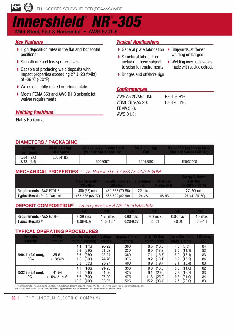
7/18/2019 c110 - Lincoln Electric Consumables 2014
http://slidepdf.com/reader/full/c110-lincoln-electric-consumables-2014 88/51188 ı T H E L I N C O L N E L E C T R I C C O M P A N Y
Innershield ®
NR ®
-305 FLUX-CORED SELF-SHIELDED (FCAW-S) WIRE
Welding Positions
Typical Applications
Flat & Horizontal
General plate fabrication
Structural fabrication,including those subjectto seismic requirements
Bridges and offshore rigs
Shipyards, stiffenerwelding on barges
Welding over tack weldsmade with stick electrode
High deposition rates in the flat and horizontalpositions
Smooth arc and low spatter levels
Capable of producing weld deposits withimpact properties exceeding 27 J (20 ft•lbf)at -29°C (-20°F)
Welds on lightly rusted or primed plate
Meets FEMA 353 and AWS D1.8 seismic lotwaiver requirements
Conformances
Mild Steel, Flat & Horizontal • AWS E70T-6
Key Features
AWS A5.20/A5.20M:
ASME SFA-A5.20:
FEMA 353:
AWS D1.8:
E70T-6 H16
E70T-6 H16
DIAMETERS / PACKAGING
Diameter 25 lb (11.3 kg)Steel Spool
25 lb (11.3 kg) Plastic Spool(Vacuum Sealed Foil Bag)
50 lb (22.7 kg)Coil
50 lb (22.7 kg) Plastic Spool(Vacuum Sealed Foil Bag)in (mm)
5/643/32
(2.0)(2.4)
ED034185ED030971 ED012593 ED030005
DEPOSIT COMPOSITION(1) – As Required per AWS A5.20/A5.20M %C %Mn %Si %S %P %Al
Requirements - AWS E70T-6 0.30 max. 1.75 max. 0.60 max. 0.03 max. 0.03 max. 1.8 max.
Typical Results(3) 0.06-0.09 1.08-1.57 0.20-0.27 ≤0.01 ≤0.01 0.9-1.1
(1)Typical all weld metal. (2)Measured with 0.2% offset. (3)See test results disclaimer on pg. 18. (4)Use CTWD of 2 1/4 in (54 mm) for wire feed speeds greater than 300 ipm.NOTE: FEMA 353 and AWS D1.8 structural steel seismic supplement test data can be found on this product at www.lincolnelectric.com.
TYPICAL OPERATING PROCEDURESDiameter,Polarity
CTWDmm (in)
Wire Feed Speed Voltage(volts)
Approx. Current(amps)
Melt-Off Rate Deposition Rate Efficiency(%)m/min (in/min) kg/hr (lb/hr) kg/hr (lb/hr)
5/64 in (2.0 mm),DC+
35-51(1 3/8-2)
4.45.66.67.68.3
(175)(220)(260)(300)(325)
20-2221-2322-2424-2625-27
300330360375400
8.56.07.18.28.9
(10.5)(13.3)(15.7)(18.1)(19.7)
4.05.05.96.97.4
(8.8)(11.1)(13.1)(15.2)(16.4)
8483838483
3/32 in (2.4 mm),DC+
41-54(1 5/8-2 1/4)(4)
4.16.17.6
10.2
(160)(240)(300)(400)
21-2324-2627-2933-35
330425475525
6.09.1
11.315.2
(13.3)(20.0)(25.0)(33.4)
5.07.69.5
12.7
(11.0)(16.7)(21.0)(28.0)
82838483
MECHANICAL PROPERTIES(1) – As Required per AWS A5.20/A5.20M
Yield Strength(2)
Tensile Strength
Elongation
Hardness
Charpy V-NotchJ (ft•lbf)
MPa (ksi) MPa (ksi) % Rockwell B @ -29°C (-20°F)
Requirements - AWS E70T-6 400 (58) min. 480-655 (70-95) 22 min. – 27 (20) min.
Typical Results(3) - As-Welded 465-535 (68-77) 565-620 (82-90) 24-28 88-93 27-41 (20-30)
uctural Welding Code
smic Supplement

7/18/2019 c110 - Lincoln Electric Consumables 2014
http://slidepdf.com/reader/full/c110-lincoln-electric-consumables-2014 89/511W E L D I N G C O N S U M A B L E S C A TA L O G ı 89
FLUX-CORED SELF-SHIELDED (FCAW-S) WIRE
Innershield ®
NR ®
-311
Welding Positions
Typical Applications
Flat & Horizontal
Recommended for fillet,lap and butt welds on3.2 mm (1/8 in) andthicker steel, includingsome low alloy steels
General fabrication
Assembly welding
High deposition rates and fast travel speeds
Easy slag removal Optimal toe wash-in
Deep penetration
High resistance to cracking
Welds on lightly rusted or primed plate
Conformances
AWS E70T-7 • Mild Steel, Flat & Horizontal
Key Features
AWS A5.20/A5.20M:
ASME SFA-A5.20:
ABS:
CWB/CSA W48-06:
E70T-7
E70T-7
E70T-7
E492T-7
DIAMETERS / PACKAGINGDiameter 14 lb (6.4 kg) Coil
56 lb (25.4 kg) Master Carton25 lb (11.3 kg)
Steel Spool50 lb (22.7 kg)
Coil600 lb (272 kg)
Speed-Feed® Reel600 lb (272 kg)
Speed-Feed®Drumin (mm)
5/643/327/64
(2.0)(2.4)(2.8)
ED014464 ED030649 ED014459ED012629ED012632 ED012633
ED012628
DEPOSIT COMPOSITION(1) – As Required per AWS A5.20/A5.20M %C %Mn %Si %S %P %Al
Requirements - AWS E70T-7 0.30 max. 1.75 max. 0.60 max. 0.03 max. 0.03 max. 1.8 max.
Typical Results(3) 0.25-0.29 0.44-0.51 0.09-0.12 ≤0.01 ≤0.01 1.4-1.7
(1)Typical all weld metal. (2)Measured with 0.2% offset. (3)See test results disclaimer on pg. 18.
MECHANICAL PROPERTIES(1) – As Required per AWS A5.20/A5.20M Yield Strength(2) Tensile Strength Elongation Hardness
MPa (ksi) MPa (ksi) % Rockwell B
Requirements - AWS E70T-7 400 (58) min. 480-655 (70-95) 22 min. –
Typical Results(3) - As-Welded 420-475 (61-69) 600-645 (87-93) 23-26 88-92
TYPICAL OPERATING PROCEDURES
Diameter,Polarity
CTWDmm (in)
Wire Feed Speed Voltage(volts)
Approx. Current(amps)
Melt-Off Rate Deposition Rate Efficiency(%)m/min (in/min) kg/hr (lb/hr) kg/hr (lb/hr)
5/64 in (2.0 mm),DC- 38(1 1/2)
2.5
4.16.17.6
(100)
(160)(240)(300)
20-23
24-2825-2927-31
190
275355410
2.9
4.77.08.8
(6.4)
(10.3)(15.4)(19.3)
2.3
3.65.67.2
(5.0)
(8.0)(12.4)(15.8)
78
788082
3/32 in (2.4 mm),DC-
45(1 3/4)
1.93.43.85.36.9
(75)(135)(150)(210)(270)
20-2323-2624-2726-2828-30
200300325400450
3.25.96.69.3
11.9
(7.0)(13.1)(14.6)(20.4)(26.2)
2.54.65.27.5
10.0
(5.4)(10.2)(11.4)(16.5)(22.0)
7778788184
7/64 in (2.8 mm),DC-
45(1 3/4)
2.53.74.46.17.6
(100)(145)(175)(240)(300)
23-2625-2726-2830-3232-34
325400450550625
5.48.19.8
13.416.7
(12.0)(17.8)(21.5)(29.5)(36.9)
4.56.68.2
11.615.0
(10.0)(14.5)(18.0)(25.5)(33.0)
8382838689

7/18/2019 c110 - Lincoln Electric Consumables 2014
http://slidepdf.com/reader/full/c110-lincoln-electric-consumables-2014 90/51190 ı T H E L I N C O L N E L E C T R I C C O M P A N Y
Innershield ®
NR ®
-131FLUX-CORED SELF-SHIELDED (FCAW-S) WIRE
Welding Positions
Typical Applications
Flat & Horizontal
Single pass weldingon up to 2.8 mm(0.110 in) thicknesses
Sheet metal
Automotive
Fast travel speeds and high deposition rates
Maximum penetration Flat bead profile on butt welds
Join dissimilar plate thicknesses with evenheat distribution
Conformances
Mild Steel, Flat & Horizontal • AWS E70T-10
Key Features
AWS A5.20/A5.20M:
ASME SFA-A5.20:
E70T-10
E70T-10
DIAMETERS / PACKAGING
Diameter 600 lb (272 kg)Speed-Feed® Reelin (mm)
3/32 (2.4) ED012163
Warning
NR-131 is NOT recommended for welding multiplepasses.
DEPOSIT COMPOSITION(1) – As Required per AWS A5.20/A5.20M
%C %Mn %Si %S %P %Al
Requirements - AWS E70T-10 Not Specified
Typical Results(3) 0.22-0.26 0.42-0.65 0.20-0.27 0.005-0.007 0.007-0.02 1.18-1.49
MECHANICAL PROPERTIES(1) – As Required per AWS A5.20/A5.20M Transverse Tensile Strength
MPa (ksi)Longitudinal
Bend TestHardness
Rockwell B
Requirements - AWS E70T-10 480 (70) min. 180° over 3/4 in Radius
No openings exceeding 1/8 in
–
Typical Results(3) 505-560 (75-80) Passed 99
(1)Typical all weld metal. (2)See test results disclaimer on pg. 18.
TYPICAL OPERATING PROCEDURES
Diameter,
Polarity
CTWD
mm (in)
Wire Feed Speed Voltage
(volts)
Approx. Current
(amps)
Melt-Off Rate Deposition Rate Efficiency
(%)m/min (in/min) kg/hr (lb/hr) kg/hr (lb/hr)
3/32 in (2.4 mm),
Single Arc, DC-38
(1-1/2)
3.85.16.48.9
10.8
(150)(200)(250)(350)(425)
25-2625-2726-2726-2827-28
390490570720810
6.58.6
10.815.018.2
(14.3)(19.0)(23.7)(33.1)(40.1)
5.37.18.9
33.615.2
(11.6)(15.6)(19.6)(27.6)(33.6)
8182828383
3/32 in (2.4 mm),
Twinarc, DC-44
(1-3/4)
3.34.45.77.08.3
(130)(175)(225)(275)(325)
25-2626-2726-2827-2928-30
55074091010301090
11.115.019.323.527.9
(24.5)(33.0)(42.5)(51.9)(61.4)
8.112.015.819.121.9
(17.9)(26.4)(34.8)(42.0)(48.2)
7279818078

7/18/2019 c110 - Lincoln Electric Consumables 2014
http://slidepdf.com/reader/full/c110-lincoln-electric-consumables-2014 91/511W E L D I N G C O N S U M A B L E S C A TA L O G ı 91
FLUX-CORED SELF-SHIELDED (FCAW-S) WIRE
Innershield ®
NR ®
-152
Welding Positions
Typical Applications
All
Single pass weldingon thicknesses from
0.8 mm - 4.8 mm(0.030 in - 3/16 in)
Spot or shortintermittent welds
Continuous weldingon galvanized or zinc
coated carbon steel Automotive
Transportation
Designed for high speed welding of speciallycoated steels
Soft, consistent arc
Porosity resistant
Excellent overlapping capabilities
Ideal for robotic applications
Conformances
AWS E71T-14 • Mild Steel, All Position
Key Features
AWS A5.20/A5.20M:
ASME SFA-A5.20:
E71T-14
E71T-14
DIAMETERS / PACKAGINGDiameter 25 lb (11.3 kg)
Plastic Spool50 lb (22.7 kg)
Coil500 lb (227 kg)
Speed-Feed® Drumin (mm)
0.0450.0620.068
(1.1)(1.6)(1.7)
EDS01702ED012185ED012186
ED024301
Warning NR-152 is NOT recommended for welding multiplepasses.
Maximum Plate Thickness
Diameter - in (mm) Maximum Plate Thickness - in (mm)
1/16 (1.6)0.068 (1.7)
3/16 (4.8)3/16 (4.8)
DEPOSIT COMPOSITION(1) – As Required per AWS A5.20/A5.20M
%C %Mn %Si %S %P %Al
Requirements - AWS E71T-14 Not Specified
Typical Results(2) 0.25-0.30 0.83-1.04 0.20-0.23 0.006-0.01 0.005-0.02 1.08-1.38
MECHANICAL PROPERTIES(1)
– As Required per AWS A5.20/A5.20M Transverse Tensile Strength
MPa (ksi)Longitudinal
Bend TestHardness
Rockwell B
Requirements - AWS E71T-14 480 (70) min. 180° over 3/4 in Radius / No openings exceeding 1/8 in –
Typical Results(2) 480-550 (70-80) Passed 93
(1)Typical all weld metal. (2)See test results disclaimer on pg. 18.NOTE: The preferred drag angle is 15°, however, NR-152 is capable of welding at zero drag angle, facilitating easy fixturing in automatic applications.
TYPICAL OPERATING PROCEDURES
Diameter,Polarity
CTWDmm (in)
Wire Feed Speed Voltage(volts)
Approx. Current(amps)
Melt-Off Rate Deposition Rate Efficiency(%)m/min (in/min) kg/hr (lb/hr) kg/hr (lb/hr)
1/16 in (1.6 mm),DC-
16(5/8)
0.81.01.31.82.8
(30)(40)(50)(70)(110)
13-1414-1515-1616-1719-20
90115140185265
0.50.80.91.42.1
(1.3)(1.8)(2.2)(3.1)(4.8)
0.50.70.91.32.0
(1.2)(1.6)(2.0)(2.8)(4.4)
9288909091
0.068 in (1.7 mm),Twinarc, DC-
19(3/4)
0.81.01.31.52.02.8
(30)(40)(50)(60)(80)(110)
13-1413-1414-1515-1616-1720-21
6895120145190240
0.70.91.21.41.92.7
(1.6)(2.2)(2.7)(3.3)(4.4)(6.0)
0.60.91.11.31.82.4
(1.4)(1.9)(2.4)(2.9)(3.9)(5.4)
878688878890
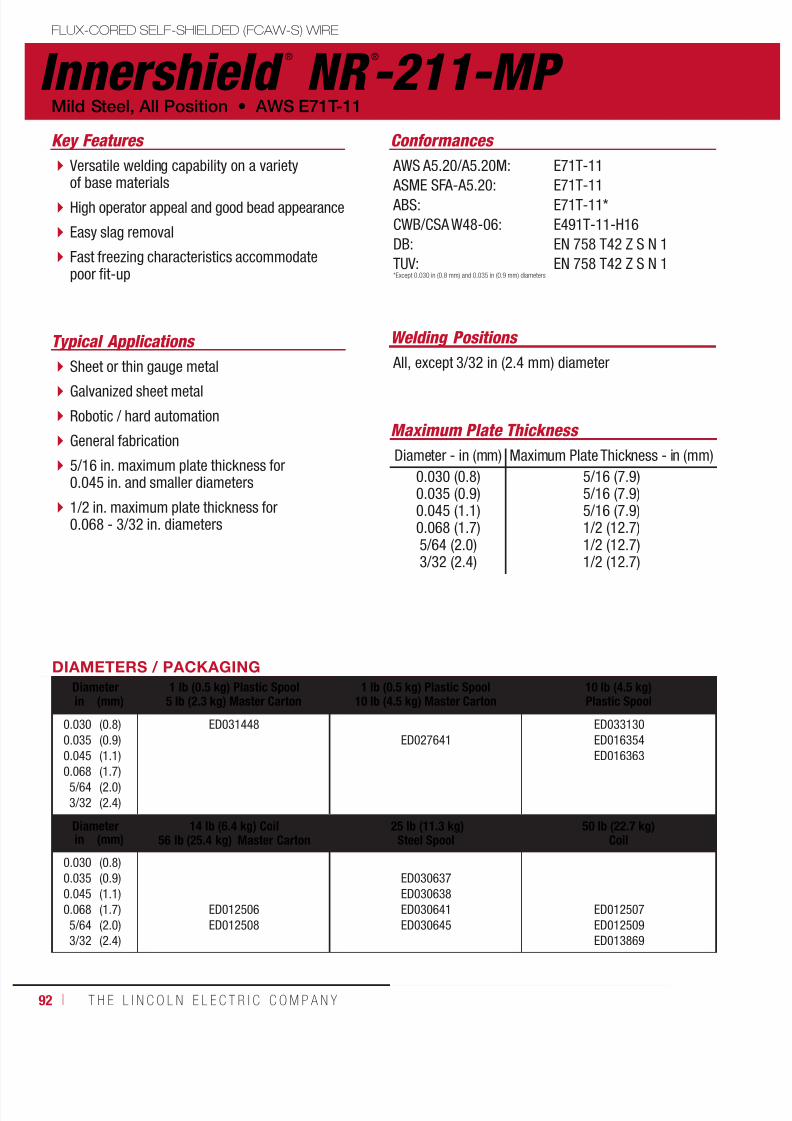
7/18/2019 c110 - Lincoln Electric Consumables 2014
http://slidepdf.com/reader/full/c110-lincoln-electric-consumables-2014 92/51192 ı T H E L I N C O L N E L E C T R I C C O M P A N Y
Innershield ®
NR ®
-211-MP FLUX-CORED SELF-SHIELDED (FCAW-S) WIRE
Welding Positions Typical Applications
All, except 3/32 in (2.4 mm) diameterSheet or thin gauge metal
Galvanized sheet metal
Robotic / hard automation
General fabrication
5/16 in. maximum plate thickness for0.045 in. and smaller diameters
1/2 in. maximum plate thickness for0.068 - 3/32 in. diameters
Versatile welding capability on a varietyof base materials
High operator appeal and good bead appearance
Easy slag removal
Fast freezing characteristics accommodatepoor fit-up
Conformances
Mild Steel, All Position • AWS E71T-11
Key Features
AWS A5.20/A5.20M:
ASME SFA-A5.20: ABS:
CWB/CSA W48-06:
DB:
TUV:
E71T-11
E71T-11E71T-11*
E491T-11-H16
EN 758 T42 Z S N 1
EN 758 T42 Z S N 1
DIAMETERS / PACKAGING
Diameter 1 lb (0.5 kg) Plastic Spool5 lb (2.3 kg) Master Carton
1 lb (0.5 kg) Plastic Spool10 lb (4.5 kg) Master Carton
10 lb (4.5 kg)Plastic Spoolin (mm)
0.0300.0350.045
0.0685/643/32
(0.8)(0.9)(1.1)
(1.7)(2.0)(2.4)
ED031448ED027641
ED033130ED016354ED016363
Diameter 14 lb (6.4 kg) Coil56 lb (25.4 kg) Master Carton
25 lb (11.3 kg)Steel Spool
50 lb (22.7 kg)Coilin (mm)
0.0300.0350.0450.0685/643/32
(0.8)(0.9)(1.1)(1.7)(2.0)(2.4)
ED012506ED012508
ED030637ED030638ED030641ED030645
ED012507ED012509ED013869
*Except 0.030 in (0.8 mm) and 0.035 in (0.9 mm) diameters
Maximum Plate Thickness
Diameter - in (mm) Maximum Plate Thickness - in (mm)
0.030 (0.8)0.035 (0.9)0.045 (1.1)0.068 (1.7)5/64 (2.0)3/32 (2.4)
5/16 (7.9)5/16 (7.9)5/16 (7.9)1/2 (12.7)1/2 (12.7)1/2 (12.7)
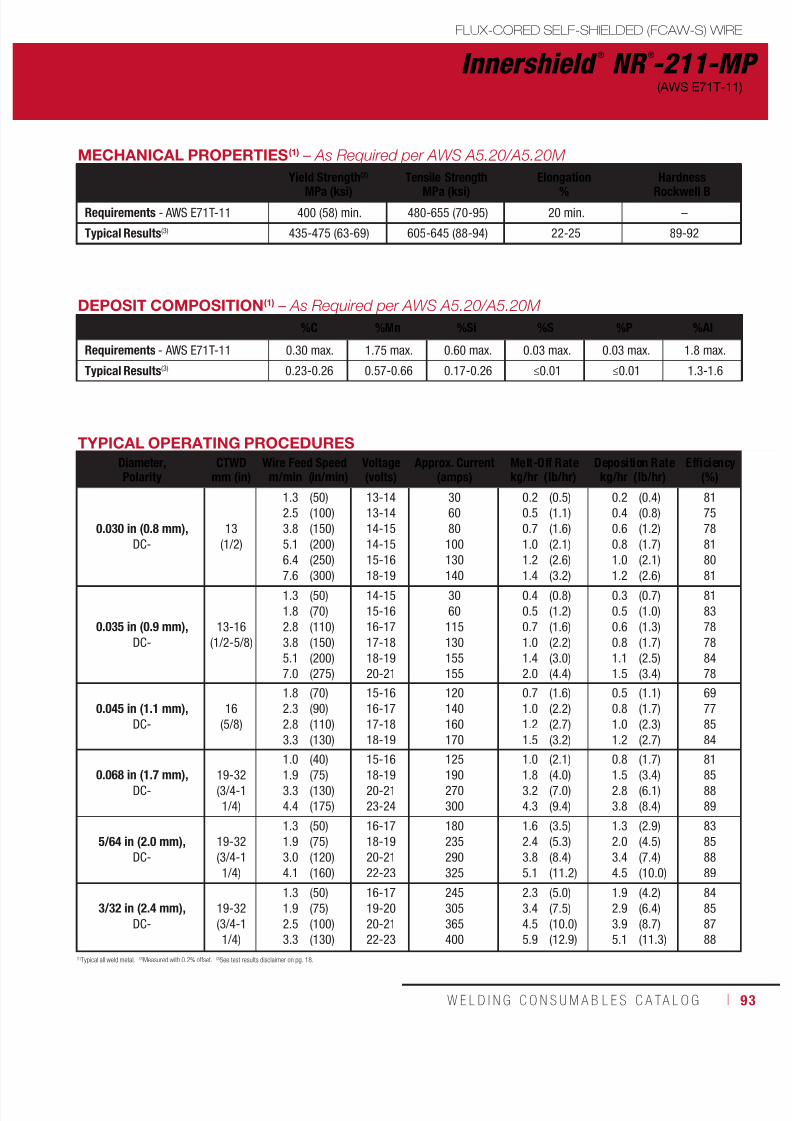
7/18/2019 c110 - Lincoln Electric Consumables 2014
http://slidepdf.com/reader/full/c110-lincoln-electric-consumables-2014 93/511W E L D I N G C O N S U M A B L E S C A TA L O G ı 93
Innershield ®
NR ®
-211-MP
FLUX-CORED SELF-SHIELDED (FCAW-S) WIRE
(AWS E71T-11)
DEPOSIT COMPOSITION(1) – As Required per AWS A5.20/A5.20M
%C %Mn %Si %S %P %Al
Requirements - AWS E71T-11 0.30 max. 1.75 max. 0.60 max. 0.03 max. 0.03 max. 1.8 max.
Typical Results(3) 0.23-0.26 0.57-0.66 0.17-0.26 ≤0.01 ≤0.01 1.3-1.6
(1)Typical all weld metal. (2)Measured with 0.2% offset. (3)See test results disclaimer on pg. 18.
TYPICAL OPERATING PROCEDURES
Diameter,Polarity
CTWDmm (in)
Wire Feed Speed Voltage(volts)
Approx. Current(amps)
Melt-Off Rate Deposition Rate Efficiency(%)m/min (in/min) kg/hr (lb/hr) kg/hr (lb/hr)
0.030 in (0.8 mm),
DC-13
(1/2)
1.32.53.85.16.4
7.6
(50)(100)(150)(200)(250)
(300)
13-1413-1414-1514-1515-16
18-19
306080100130
140
0.20.50.71.01.2
1.4
(0.5)(1.1)(1.6)(2.1)(2.6)
(3.2)
0.20.40.60.81.0
1.2
(0.4)(0.8)(1.2)(1.7)(2.1)
(2.6)
8175788180
81
0.035 in (0.9 mm),
DC-13-16
(1/2-5/8)
1.31.82.83.85.17.0
(50)(70)(110)(150)(200)(275)
14-1515-1616-1717-1818-1920-21
3060115130155155
0.40.50.71.01.42.0
(0.8)(1.2)(1.6)(2.2)(3.0)(4.4)
0.30.50.60.81.11.5
(0.7)(1.0)(1.3)(1.7)(2.5)(3.4)
818378788478
0.045 in (1.1 mm),
DC-16
(5/8)
1.82.32.83.3
(70)(90)(110)(130)
15-1616-1717-1818-19
120140160170
0.71.01.21.5
(1.6)(2.2)(2.7)(3.2)
0.50.81.01.2
(1.1)(1.7)(2.3)(2.7)
69778584
0.068 in (1.7 mm),
DC-19-32(3/4-11/4)
1.01.93.34.4
(40)(75)(130)(175)
15-1618-1920-2123-24
125190270300
1.01.83.24.3
(2.1)(4.0)(7.0)(9.4)
0.81.52.83.8
(1.7)(3.4)(6.1)(8.4)
81858889
5/64 in (2.0 mm),
DC-19-32(3/4-11/4)
1.31.93.04.1
(50)(75)(120)(160)
16-1718-1920-2122-23
180235290325
1.62.43.85.1
(3.5)(5.3)(8.4)(11.2)
1.32.03.44.5
(2.9)(4.5)(7.4)(10.0)
83858889
3/32 in (2.4 mm),
DC-19-32(3/4-11/4)
1.31.92.53.3
(50)(75)(100)(130)
16-1719-2020-2122-23
245305365400
2.33.44.55.9
(5.0)(7.5)(10.0)(12.9)
1.92.93.95.1
(4.2)(6.4)(8.7)(11.3)
84858788
MECHANICAL PROPERTIES(1) – As Required per AWS A5.20/A5.20M
Yield Strength(2)
MPa (ksi)
Tensile Strength
MPa (ksi)
Elongation
%
Hardness
Rockwell B
Requirements - AWS E71T-11 400 (58) min. 480-655 (70-95) 20 min. –
Typical Results(3) 435-475 (63-69) 605-645 (88-94) 22-25 89-92
7/18/2019 c110 - Lincoln Electric Consumables 2014
http://slidepdf.com/reader/full/c110-lincoln-electric-consumables-2014 94/51194 ı T H E L I N C O L N E L E C T R I C C O M P A N Y
Innershield ®
NR ®
-203MP FLUX-CORED SELF-SHIELDED (FCAW-S) WIRE
Welding Positions
Typical Applications
All
General plate fabrication, including bridgefabrication, hull plate and stiffener weldingon ships and barges
Storage tanks
Structural welding
Offshore welding in TKY joints
Designed to handle poor fit-up on heavy walltubes and gaps up to 9.5 mm (3/8 in) with6.4 mm (1/4 in) offset
Fast freezing slag with excellent wash-in
Root bead capability without back-up bars
Conformances
Mild Steel, All Position • AWS E71T-8-J
Key Features
AWS A5.20/A5.20M:
ASME SFA-A5.20: ABS:
Lloyd’s Register:
DNV Grade:
GL:
BV Grade:
CWB/CSA W48-06:
E71T-8-JH16
E71T-8-JH163YSA
3YS H15
III YMS H10
3YH15S
SA3YMH
E491T-8 H16
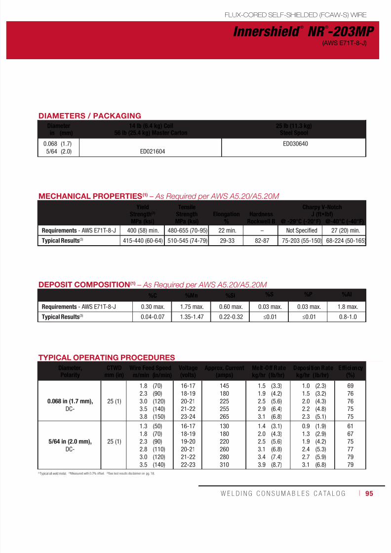
7/18/2019 c110 - Lincoln Electric Consumables 2014
http://slidepdf.com/reader/full/c110-lincoln-electric-consumables-2014 95/511W E L D I N G C O N S U M A B L E S C A TA L O G ı 95
DIAMETERS / PACKAGING
Diameter 14 lb (6.4 kg) Coil56 lb (25.4 kg) Master Carton
25 lb (11.3 kg)Steel Spoolin (mm)
0.0685/64
(1.7)(2.0) ED021604
ED030640
DEPOSIT COMPOSITION(1) – As Required per AWS A5.20/A5.20M %C %Mn %Si %S %P %Al
Requirements - AWS E71T-8-J 0.30 max. 1.75 max. 0.60 max. 0.03 max. 0.03 max. 1.8 max.
Typical Results(3) 0.04-0.07 1.35-1.47 0.22-0.32 ≤0.01 ≤0.01 0.8-1.0
MECHANICAL PROPERTIES(1) – As Required per AWS A5.20/A5.20M
YieldStrength(2)
TensileStrength Elongation Hardness
Charpy V-NotchJ (ft•lbf)
MPa (ksi) MPa (ksi) % Rockwell B @ -29°C (-20°F) @-40°C (-40°F)
Requirements - AWS E71T-8-J 400 (58) min. 480-655 (70-95) 22 min. – Not Specified 27 (20) min.
Typical Results(3) 415-440 (60-64) 510-545 (74-79) 29-33 82-87 75-203 (55-150) 68-224 (50-165)
(1)Typical all weld metal. (2)Measured with 0.2% offset. (3)See test results disclaimer on pg. 18.
TYPICAL OPERATING PROCEDURES
Diameter,Polarity
CTWDmm (in)
Wire Feed Speed Voltage(volts)
Approx. Current(amps)
Melt-Off Rate Deposition Rate Efficiency(%)
m/min (in/min) kg/hr (lb/hr) kg/hr (lb/hr)
0.068 in (1.7 mm),
DC-25 (1)
1.82.33.03.53.8
(70)(90)(120)(140)(150)
16-1718-1920-2121-2223-24
145180225255265
1.51.92.52.93.1
(3.3)(4.2)(5.6)(6.4)(6.8)
1.01.52.02.22.3
(2.3)(3.2)(4.3)(4.8)(5.1)
6976767575
5/64 in (2.0 mm),
DC-25 (1)
1.31.82.32.83.03.5
(50)(70)(90)(110)(120)(140)
16-1718-1919-2020-2121-2222-23
130180220260280310
1.42.02.53.13.43.9
(3.1)(4.3)(5.6)(6.8)(7.4)(8.7)
0.91.31.92.42.73.1
(1.9)(2.9)(4.2)(5.3)(5.9)(6.8)
616775777979
FLUX-CORED SELF-SHIELDED (FCAW-S) WIRE
Innershield ®
NR ®
-203MP(AWS E71T-8-J)

7/18/2019 c110 - Lincoln Electric Consumables 2014
http://slidepdf.com/reader/full/c110-lincoln-electric-consumables-2014 96/51196 ı T H E L I N C O L N E L E C T R I C C O M P A N Y
Innershield ®
NR ®
-232
Welding Positions
Typical Applications
All
Structural fabrication, including those subject toseismic requirements
General plate fabrication
Hull plate and stiffener welding on ships andbarges
Machinery parts, tanks, hoppers, racks andscaffolding
High deposition rates for out-of-positionwelding
Penetrating arc
Fast freezing, easy to remove slag system
Meets AWS D1.8 seismic lot waiverrequirements
Conformances
Mild Steel, All Position • AWS E71T-8
Key Features
AWS A5.20/A5.20M:
ASME SFA-A5.20: ABS:
Lloyd’s Register:
DNV Grade:
GL:
BV Grade:
CWB/CSA W48-06:
DB:
TUV:
MIL-E-24403/1:*
FEMA 353 AWS D1.8
E71T-8-H16
E71T-8-H163YSA
3YS H15
III YMS H15
3YH10S
SA3YMH
E491T-8 H16
EN 758 T42 3 Y N 2
EN 758 T42 3 Y N 2
MIL-71T-8AS
*Military Grade Classification of MIL-71T-8AS for 0.068 in (1.7 mm) and 0.072 in (1.8 mm) diameters only.
FLUX-CORED SELF-SHIELDED (FCAW-S) WIREuctural Welding Code
smic Supplement

7/18/2019 c110 - Lincoln Electric Consumables 2014
http://slidepdf.com/reader/full/c110-lincoln-electric-consumables-2014 97/511W E L D I N G C O N S U M A B L E S C A TA L O G ı 97
DIAMETERS / PACKAGING
Diameter 13.5 lb (6.1 kg) Coil
54 lb (24.5 kg) Master Carton
13.5 lb (6.1 kg) Coil
54 lb (24.5 kg) Hermetically Sealed Pail
25 lb (11.3 kg)
Steel Spoolin (mm)
0.0680.0725/64
(1.7)(1.8)(2.0)
ED012518ED012522ED012525
ED030232ED030643ED030644ED030647
Diameter 25 lb (11.3 kg) Plastic Spool(Vacuum Sealed Foil Bag)
50 lb (22.7 kg)Coilin (mm)
0.0680.0725/64
(1.7)(1.8)(2.0)
ED030949ED012519ED012523ED012526
DEPOSIT COMPOSITION(1) – As Required per AWS A5.20/A5.20M
%C %Mn %Si %S %P %Al
Requirements - AWS E71T-8 0.30 max. 1.75 max. 0.60 max. 0.03 max. 0.03 max. 1.8 max.
Typical Results(3) 0.16-0.18 0.61-0.72 0.26-0.33 ≤0.01 ≤0.01 0.5-0.8
MECHANICAL PROPERTIES(1) – As Required per AWS A5.20/A5.20M
Yield Strength(2)
MPa (ksi)Tensile Strength
MPa (ksi)Elongation
%Hardness
Rockwell BCharpy V-Notch / J ft•lbf)
@ -29°C (-20°F)
Requirements - AWS E71T-8 400 (58) min. 480-655 (70-95) 22 min. – 27 (20) min.
Typical Results(3) - As-Welded 460-520 (66-75) 575-615 (83-89) 25-31 87-90 47-75 (35-55)
(1)Typical all weld metal. (2)Measured with 0.2% offset. (3)See test results disclaimer on pg. 18.NOTE: FEMA 353 and AWS D1.8 structural steel seismic supplement test data can be found on this product at www.lincolnelectric.com.
TYPICAL OPERATING PROCEDURES
Diameter,Polarity
CTWD(6)
mm (in)Wire Feed Speed Voltage(7)
(volts)Approx. Current
(amps)Melt-Off Rate Deposition Rate Efficiency
(%)m/min (in/min) kg/hr (lb/hr) kg/hr (lb/hr)
0.068 in (1.7 mm),
DC-19-32
(3/4-1 1/4)
2.83.33.84.35.06.4
7.4
(110)(130)(150)(170)(195)(250)
(320)
18-1919-2119-2120-2223-2423-24
25-27
195225250270300350
400
2.32.83.23.54.35.4
6.9
(5.0)(6.2)(7.1)(7.8)(9.4)(11.8)
(15.2)
1.82.02.42.83.24.0
5.2
(3.9)(4.6)(5.3)(6.1)(7.0)(9.0)
(11.4)
787475787476
75
0.072 in (1.8 mm),
DC-19-32
(3/4-1 1/4)
2.03.53.94.36.47.4
(80)(140)(155)(170)(250)(290)
16-1818-2119-2220-2322-2423-25
130225240255315350
1.83.13.33.65.36.2
(4.0)(6.8)(7.2)(8.0)(11.7)(13.6)
1.52.52.72.94.35.0
(3.3)(5.5)(6.0)(6.5)(9.6)(11.0)
838183818281
5/64 in (2.0 mm),
DC-19-32
(3/4-1 1/4)
1.52.93.03.34.6
(60)(115)(120)(130)(180)
16-1719-2019-2020-2122-23
145260270285365
1.73.23.33.55.0
(3.7)(7.0)(7.3)(7.8)(10.9)
1.22.52.62.83.9
(2.7)(5.5)(5.7)(6.2)(8.7)
7378787980
FLUX-CORED SELF-SHIELDED (FCAW-S) WIRE
Innershield ®
NR ®
-232(AWS E71T-8)

7/18/2019 c110 - Lincoln Electric Consumables 2014
http://slidepdf.com/reader/full/c110-lincoln-electric-consumables-2014 98/51198 ı T H E L I N C O L N E L E C T R I C C O M P A N Y
Innershield ®
NR ®
-233
Welding Positions
Typical Applications All
Structural fabrication, including those subjectto seismic requirements
General plate fabrication
Ship and barge fabrication
Vertical up and overhead fillets and groovewelds
High deposition rates for out-of-position welding
Welder-friendly, easy to use and great beadappearance
Minimal gas marking
Meets AWS D1.8 seismic lot waiver requirements
Conformances
Mild Steel, All Position • AWS E71T-8
Key Features
AWS A5.20/A5.20M:
ASME SFA-A5.20: ABS:
EN ISO 17632-B:
FEMA 353
AWS D1.8
E71T-8-H16
E71T-8-H16E71T-8-H16
T493T8-1NA-H15
Notes
Innershield® K126 Gun Assembly requires one ofthe following gun tube assemblies for better wirefeeding - KP2454-1 (62°, 7.5 in), KP2455-1(45°, 6 in), KP2456-1 (30°, 12 in)
FLUX-CORED SELF-SHIELDED (FCAW-S) WIREuctural Welding Code
smic Supplement
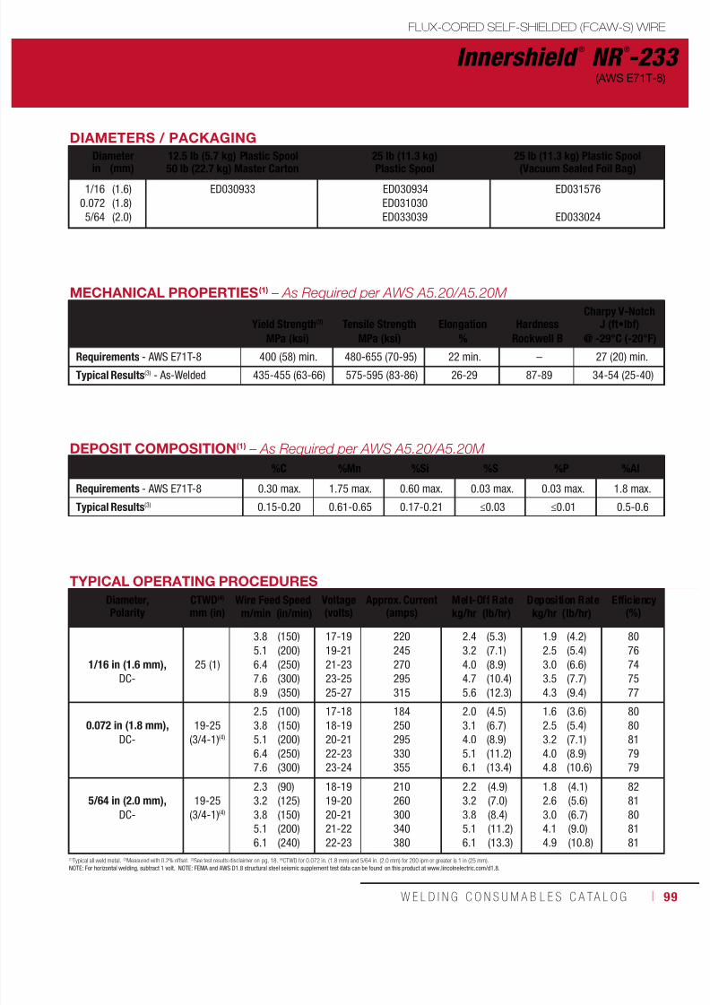
7/18/2019 c110 - Lincoln Electric Consumables 2014
http://slidepdf.com/reader/full/c110-lincoln-electric-consumables-2014 99/511W E L D I N G C O N S U M A B L E S C A TA L O G ı 99
DIAMETERS / PACKAGING
Diameter 12.5 lb (5.7 kg) Plastic Spool
50 lb (22.7 kg) Master Carton
25 lb (11.3 kg)
Plastic Spool
25 lb (11.3 kg) Plastic Spool
(Vacuum Sealed Foil Bag)in (mm)1/16
0.0725/64
(1.6)(1.8)(2.0)
ED030933 ED030934ED031030ED033039
ED031576
ED033024
Innershield ®
NR ®
-233(AWS E71T-8)
DEPOSIT COMPOSITION(1) – As Required per AWS A5.20/A5.20M
%C %Mn %Si %S %P %Al
Requirements - AWS E71T-8 0.30 max. 1.75 max. 0.60 max. 0.03 max. 0.03 max. 1.8 max.
Typical Results(3) 0.15-0.20 0.61-0.65 0.17-0.21 ≤0.03 ≤0.01 0.5-0.6
(1)Typical all weld metal. (2)Measured with 0.2% offset. (3)See test results disclaimer on pg. 18. (4)CTWD for 0.072 in. (1.8 mm) and 5/64 in. (2.0 mm) for 200 ipm or greater is 1 in (25 mm).NOTE: For horizontal welding, subtract 1 volt. NOTE: FEMA and AWS D1.8 structural steel seismic supplement test data can be found on this product at www.lincolnelectric.com/d1.8.
TYPICAL OPERATING PROCEDURES
Diameter,Polarity
CTWD(4)
mm (in)Wire Feed Speed Voltage
(volts)Approx. Current
(amps)Melt-Off Rate Deposition Rate Efficiency
(%)m/min (in/min) kg/hr (lb/hr) kg/hr (lb/hr)
1/16 in (1.6 mm),
DC-25 (1)
3.85.16.47.68.9
(150)(200)(250)(300)(350)
17-1919-2121-2323-2525-27
220245270295315
2.43.24.04.75.6
(5.3)(7.1)(8.9)(10.4)(12.3)
1.92.53.03.54.3
(4.2)(5.4)(6.6)(7.7)(9.4)
8076747577
0.072 in (1.8 mm),
DC-19-25
(3/4-1)(4)
2.53.85.16.47.6
(100)(150)(200)(250)(300)
17-1818-1920-2122-2323-24
184250295330355
2.03.14.05.16.1
(4.5)(6.7)(8.9)(11.2)(13.4)
1.62.53.24.04.8
(3.6)(5.4)(7.1)(8.9)(10.6)
8080817979
5/64 in (2.0 mm),
DC-19-25
(3/4-1)(4)
2.33.23.85.16.1
(90)(125)(150)(200)(240)
18-1919-2020-2121-2222-23
210260300340380
2.23.23.85.16.1
(4.9)(7.0)(8.4)(11.2)(13.3)
1.82.63.04.14.9
(4.1)(5.6)(6.7)(9.0)(10.8)
8281808181
MECHANICAL PROPERTIES(1) – As Required per AWS A5.20/A5.20M
Yield Strength(2) Tensile Strength Elongation HardnessCharpy V-Notch
J (ft•lbf)
MPa (ksi) MPa (ksi) % Rockwell B @ -29°C (-20°F)Requirements - AWS E71T-8 400 (58) min. 480-655 (70-95) 22 min. – 27 (20) min.
Typical Results(3) - As-Welded 435-455 (63-66) 575-595 (83-86) 26-29 87-89 34-54 (25-40)
FLUX-CORED SELF-SHIELDED (FCAW-S) WIRE

7/18/2019 c110 - Lincoln Electric Consumables 2014
http://slidepdf.com/reader/full/c110-lincoln-electric-consumables-2014 100/511100 ı T H E L I N C O L N E L E C T R I C C O M P A N Y
Innershield ®
NR ®
-311 Ni
Welding Positions Typical Applications
Flat & HorizontalFillet and lap welds
Horizontal and square edge butt welds, suchas column-to-column structural connections
Deep groove welds
Structural fabrication
Weathering steels
Designed to provide a nominal 1.5% nickelweld deposit
High deposition rates and fast travel speeds
Capable of producing weld deposits withimpact properties exceeding 27 J (20 ft•lbf)at -29°C (-20°F)
Color match on weathering steel applications
3/32 in (2.4 mm) diameter meets FEMA 353and AWS D1.8 seismic lot waiver requirements
Conformances
Low Alloy, Flat & Horizontal • AWS E70T7-K2, E80TG-K2
Key Features
AWS A5.29/A5.29M:
ASME SFA-A5.29: ABS:
Lloyd’s Register:
DNV Grade:
GL:
BV Grade:
DB:
FEMA 353:
AWS D1.8:
E70T7-K2-H16, E80TG-K2
E70T7-K2-H16, E80TG-K22YSA
2YS
II YMS
2YS
SA2YM
EN 758 T42 2 1, 5Ni W N 5
3/32 in (2.4 mm) only
3/32 in (2.4 mm) only
FLUX-CORED SELF-SHIELDED (FCAW-S) WIREuctural Welding Code
smic Supplement

7/18/2019 c110 - Lincoln Electric Consumables 2014
http://slidepdf.com/reader/full/c110-lincoln-electric-consumables-2014 101/511W E L D I N G C O N S U M A B L E S C A TA L O G ı 101
Innershield ®
NR ®
-311 Ni(AWS E70T7-K2, E80TG-K2)
DEPOSIT COMPOSITION(1) – As Required per AWS A5.29/A5.29M
%C %Mn %Si %S %P
Requirements - AWS E70T7-K2 / E80TG-K2 0.15 max. 0.50-1.75 0.80 max. 0.030 max. 0.030 max.
Typical Results(3) 0.06-0.08 1.25-1.40 0.18-0.22 ≤0.003 0.005-0.008
%Ni %Cr %Mo %V %Al
Requirements - AWS E70T7-K2 / E80TG-K2 1.00-2.00 0.15 max. 0.35 max. 0.05 max. 1.8 max.Typical Results(3) 1.29-1.56 0.03-0.04 ≤0.03 – 1.0-1.3
(1)Typical all weld metal. (2)Measured with 0.2% offset. (3)See test results disclaimer on pg. 18.NOTE: FEMA and AWS D1.8 structural steel seismic supplement test data can be found on this product at www.lincolnelectric.com.
TYPICAL OPERATING PROCEDURES
Diameter,Polarity
CTWDmm (in)
Wire Feed Speed Voltage(volts)
Approx. Current(amps)
Melt-Off Rate Deposition Rate Efficiency(%)m/min (in/min) kg/hr (lb/hr) kg/hr (lb/hr)
5/64 in (2.0 mm),
DC-32
(1 1/4)
2.53.34.15.16.1
(100)(130)(160)(200)(240)
21-2324-2625-2726-2827-29
170205235270295
2.53.34.05.06.1
(5.5)(7.2)(8.8)(11.0)(13.3)
1.82.42.93.84.5
(3.9)(5.2)(6.5)(8.3)(10.0)
7072737575
3/32 in (2.4 mm),
DC-38
(1 1/2)
1.92.53.13.84.45.1
(75)(100)(125)(150)(175)(200)
20-2221-2323-2525-2726-2827-29
200245285330365390
2.83.84.75.76.67.6
(6.2)(8.3)(10.4)(12.5)(14.5)(16.6)
1.92.73.44.14.95.6
(4.2)(5.9)(7.5)(9.1)(10.8)(12.3)
677172727474
7/64 in (2.8 mm),
DC-44.5
(1 3/4)
2.53.54.35.16.1
(100)(140)(170)(200)(240)
22-2424-2626-2828-3029-31
310370430470520
5.27.28.9
10.412.4
(11.4)(15.8)(19.5)(22.8)(27.2)
3.85.46.67.79.2
(8.4)(11.8)(14.5)(17.0)(20.4)
7374747475
MECHANICAL PROPERTIES(1) – As Required per AWS A5.29/A5.29M
Yield Strength(2)
MPa (ksi)Tensile Strength
MPa (ksi)Elongation
%Hardness
Rockwell B
Charpy V-NotchJ (ft•lbf)
@ -29°C (-20°F)
Requirements
AWS E70T7-K2 AWS E80TG-K2
400 (58) min.470 (68) min.
480-620 (70-90)550-690 (80-100)
20 min.19 min.
– 27 (20) min.Not Specified
Typical Results(3)
As-Welded 470-515 (68-75) 575-615 (83-89) 27-30 88-93 41-87 (30-65)
FLUX-CORED SELF-SHIELDED (FCAW-S) WIRE
DIAMETERS / PACKAGING
Diameter 25 lb (11.3 kg)Steel Spool
50 lb (22.7 kg)Coil
50 lb (22.7 kg) Coil(Vacuum Sealed Foil Bag)in (mm)
5/643/327/64
(2.0)(2.4)(2.8)
ED030650ED017822ED017824
ED032530

7/18/2019 c110 - Lincoln Electric Consumables 2014
http://slidepdf.com/reader/full/c110-lincoln-electric-consumables-2014 102/511102 ı T H E L I N C O L N E L E C T R I C C O M P A N Y
DIAMETERS / PACKAGING
Diameter 25 lb (11.3 kg)
Plastic Spool
25 lb (11.3 kg) Plastic Spool
(Vacuum Sealed Foil Bag)in (mm)
3/32 (2.4) ED033628 ED033631
MECHANICAL PROPERTIES(1)
– As Required per AWS A5.29/A5.29M
Yield Strength(2)
MPa (ksi)Tensile Strength
MPa (ksi)Elongation
%Hardness
Rockwell B
Charpy V-NotchJ (ft•lbf)
@ -29°C (-20°F)
Requirements - AWS E70T7-G 400 (58) min. 485-620 (70-90) 20 Not Specified Not Specified
Typical Results(3) - As Welded 405-480 (59-70) 510-570 (74-83) 23-28 88 96-162 (71-120)
(1)Typical all weld metal. (2)Measured with 0.2% offset. (3)See test results disclaimer on pg. 18.NOTE: FEMA and AWS D1.8 structural steel seismic supplement test data can be found on this product at www.lincolnelectric.com.
CHEMICAL COMPOSITION(1) – As Required per AWS A5.29/A5.29M
%C %Mn %Si %S %P %Al
Requirements - AWS E70T7-G Not Specified 0.50 min 1.00 max 0.030 max 0.030 max 1.8 max
Typical Results(3) 0.01-0.05 2.20-2.60 0.10-0.15 0.010 max 0.010 max 0.9-1.1
TYPICAL OPERATING PROCEDURES
Diameter,Polarity
CTWDmm (in)
Wire Feed Speed Voltage(volts)
Approx. Current(amps)
Melt-Off Rate Deposition Rate Efficiency(%)m/min (in/min) kg/hr (lb/hr) kg/hr (lb/hr)
3/32 in. (2.4 mm),
DC-38 (1.5)
2.53.23.84.65.15.3
(100)(125)(150)(180)(200)(210)
22-2423-2525-2725-2727-2927-29
265320355380410425
4.04.95.97.17.98.2
(8.7)(10.7)(13.1)(15.7)(17.5)(18.1)
2.83.64.65.56.16.5
(6.1)(7.9)(10.1)(12.2)(13.4)(14.3)
707477777779
uctural Welding Code
smic Supplement
Innershield ®
NR ®
-FAB-70
Welding Positions
Notes Typical Applications
Flat & Horizontal
Welding at high heat input procedures and slowtravel speeds will significantly reduce the risk of
slag entrapment.
Structural fabrication
Proprietary design increases wire stiffnessto aid feedability and promotes a smooth arctransfer.
Capable of producing weld deposits withimpact properties exceeding an average of54 J (40 ft•lbf) at -29°C (-20°F).
Meets FEMA 353 and AWS D1.8 seismic lotwaiver requirements
Conformances
Low Alloy, Flat & Horizontal • AWS E70T7-G
Key Features
AWS A5.29/A5.29M:
ASME SFA-5.29FEMA 353
AWS D1.8
E70T7-G
E70T7-G
FLUX-CORED SELF-SHIELDED (FCAW-S) WIRE

7/18/2019 c110 - Lincoln Electric Consumables 2014
http://slidepdf.com/reader/full/c110-lincoln-electric-consumables-2014 103/511W E L D I N G C O N S U M A B L E S C A TA L O G ı 103
Innershield ®
NR ®
-203 Nickel ( 1% )
Welding Positions
Typical Applications
All
Roundabout groovewelds on heavy wall
tubular construction
Offshore
Structural fabrication
Bridges and otherstructural components
made from weatheringsteels
NACE applications
Designed to produce a nickel bearing weld deposit
Capable of producing weld deposits withimpact toughness capable of exceeding27 J (20 ft•lbf) at -29°C (-20°F)
Color match on weathering steels
Handles poor fit-up
Root bead capability
Conformances
Low Alloy, All Position • AWS E71T8-Ni1
Key Features
AWS A5.29/A5.29M:
ASME SFA-5.29: ABS:
Lloyd’s Register:
DNV Grade:
CWB/CSA W48-06:
DB:
TUV:
E71T8-Ni1-H16
E71T8-Ni1-H163YSA
3YS H15
III YMS H10
E491T8-Ni1 H16(E71TG-G-H16)
EN 758 T42 3 1Ni Y N
EN 758 T42 3 1Ni Y N
DIAMETERS / PACKAGING
Diameter 14 lb (6.4 kg) Coil56 lb (25.4 kg) Master Carton
50 lb (22.7 kg)Coilin (mm)
5/64 (2.0) ED012385 ED012386
FLUX-CORED SELF-SHIELDED (FCAW-S) WIRE
MECHANICAL PROPERTIES(1) – As Required per AWS A5.29/A5.29M
Yield Strength(2)
MPa (ksi)Tensile Strength
MPa (ksi)Elongation
%Hardness
Rockwell B
Charpy V-NotchJ (ft•lbf)
@ -29°C (-20°F)
Requirements - AWS E71T8-Ni1 400 (58) min. 480-620 (70-90) 20 min. – 27 (20) min.
Typical Results(3) - As-Welded 450-480 (65-70) 545-575 (79-83) 27-32 86-90 81-156 (60-115)
(1)Typical all weld metal. (2)Measured with 0.2% offset. (3)See test results disclaimer on pg. 18.
CHEMICAL COMPOSITION(1) – As Required per AWS A5.29/A5.29M
%C %Mn %Si %S %P
Requirements - AWS E71T8-Ni1 0.12 max. 1.50 max. 0.80 max. 0.030 max. 0.030 max.
Typical Results(3) 0.05-0.07 1.10-1.22 0.30-0.33 ≤0.010 0.005-0.008
%Ni %Cr %Mo %V %Al
Requirements - AWS E71T8-Ni1 0.80-1.10 0.15 max. 0.35 max. 0.05 max. 1.8 min.Typical Results(3) 0.89-1.05 0.02-0.03 0.01-0.02 ≤0.01 0.8-1.0
TYPICAL OPERATING PROCEDURES
Diameter,Polarity
CTWDmm (in)
Wire Feed Speed Voltage(volts)
Approx. Current(amps)
Melt-Off Rate Deposition Rate Efficiency(%)m/min (in/min) kg/hr (lb/hr) kg/hr (lb/hr)
5/64 in (2.0 mm),DC-
25 (1)
1.31.82.32.83.03.5
(50)(70)(90)(110)(120)(140)
16-1718-1919-2020-2121-2222-23
145195240275290310
1.42.02.53.03.33.9
(3.0)(4.3)(5.5)(6.7)(7.3)(8.5)
1.01.52.02.42.63.0
(2.3)(3.3)(4.3)(5.3)(5.8)(6.9)
767678797981
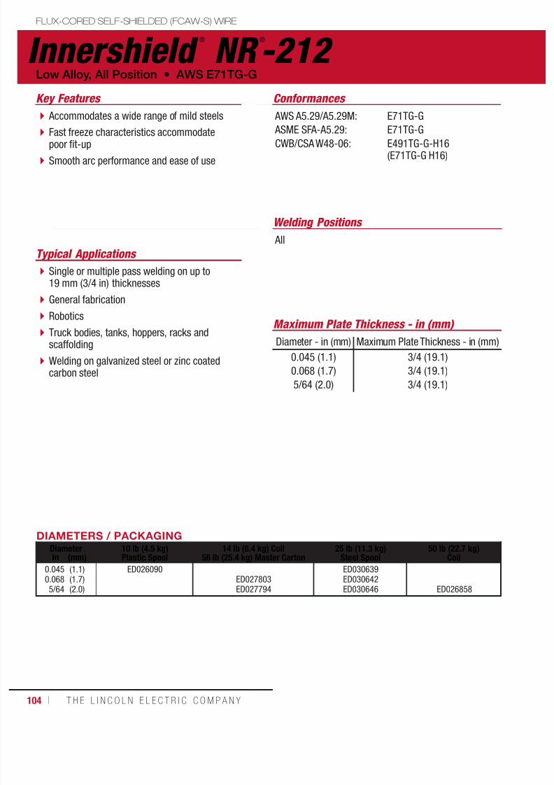
7/18/2019 c110 - Lincoln Electric Consumables 2014
http://slidepdf.com/reader/full/c110-lincoln-electric-consumables-2014 104/511104 ı T H E L I N C O L N E L E C T R I C C O M P A N Y
DIAMETERS / PACKAGINGDiameter 10 lb (4.5 kg)
Plastic Spool14 lb (6.4 kg) Coil
56 lb (25.4 kg) Master Carton25 lb (11.3 kg)
Steel Spool50 lb (22.7 kg)
Coilin (mm)
0.0450.0685/64
(1.1)(1.7)(2.0)
ED026090ED027803ED027794
ED030639ED030642ED030646 ED026858
Innershield ®
NR ®
-212 FLUX-CORED SELF-SHIELDED (FCAW-S) WIRE
Welding Positions
Typical Applications
All
Single or multiple pass welding on up to19 mm (3/4 in) thicknesses
General fabrication
Robotics
Truck bodies, tanks, hoppers, racks andscaffolding
Welding on galvanized steel or zinc coatedcarbon steel
Accommodates a wide range of mild steels
Fast freeze characteristics accommodatepoor fit-up
Smooth arc performance and ease of use
Conformances
Low Alloy, All Position • AWS E71TG-G
Key Features
AWS A5.29/A5.29M:
ASME SFA-A5.29:CWB/CSA W48-06:
E71TG-G
E71TG-GE491TG-G-H16(E71TG-G H16)
Maximum Plate Thickness - in (mm)
Diameter - in (mm) Maximum Plate Thickness - in (mm)
0.045 (1.1)
0.068 (1.7)
5/64 (2.0)
3/4 (19.1)
3/4 (19.1)
3/4 (19.1)

7/18/2019 c110 - Lincoln Electric Consumables 2014
http://slidepdf.com/reader/full/c110-lincoln-electric-consumables-2014 105/511W E L D I N G C O N S U M A B L E S C A TA L O G ı 105
MECHANICAL PROPERTIES(1) – As Required per AWS A5.29/A5.29M
Yield Strength(2)
MPa (ksi)Tensile Strength
MPa (ksi)Elongation
%Hardness
Rockwell B
Requirements - AWS E71TG-G 400 (58) min. 480-655 (70-95) 20 min. –
Typical Results(3) 440-505 (64-74) 575-605 (84-88) 24-28 89-92
Innershield ®
NR ®
-212
FLUX-CORED SELF-SHIELDED (FCAW-S) WIRE
(AWS E71TG-G)
(1)Typical all weld metal. (2)Measured with 0.2% offset. (3)See test results disclaimer on pg. 18. (4)In order to meet the alloy AWS requirements of the G group, the weld deposit needs to have the minimum, as specified in the table, of only one of these elements.
DEPOSIT COMPOSITION(1) – As Required per AWS A5.29/A5.29M
%C %Mn(4) %Si %S %P
Requirements - AWS E71TG-G Not Specified 0.50 min. 1.00 max. 0.030 max. 0.030 max.
Typical Results(3) 0.06-0.11 0.84-1.55 0.20-0.33 ≤0.003 0.006-0.009
%Ni(4) %Cr(4) %Mo(4) %V(4) %Al
Requirements - AWS E71TG-G 0.50 min. 0.30 min. 0.20 min. 0.10 min. 1.8 max.
Typical Results
(3)
1.02-1.15 0.02-0.04 ≤0.02 – 1.3-1.6
TYPICAL OPERATING PROCEDURES
Diameter,Polarity
CTWDmm (in)
Wire Feed Speed Voltage(volts)
Approx. Current(amps)
Melt-Off Rate Deposition Rate Efficiency(%)m/min (in/min) kg/hr (lb/hr) kg/hr (lb/hr)
0.045 in (1.1 mm),DC-
16 (5/8)
1.41.82.32.83.34.1
(55)(70)(90)(110)(130)(160)
14-1515-1616-1717-1818-1919-20
7590115135155170
0.50.71.01.21.41.6
(1.3)(1.6)(2.1)(2.6)(3.1)(3.5)
0.50.60.81.01.21.4
(1.1)(1.4)(1.8)(2.2)(2.6)(3.0)
848785848385
0.068 in (1.7 mm),DC-
25 (1)
1.51.92.33.03.84.4
(60)(75)(90)(120)(150)(175)
16-1717-1818-1919-2020-2122-23
145180200230255275
1.41.72.02.73.33.9
(3.1)(3.8)(4.5)(6.0)(7.4)(8.7)
1.11.41.72.32.93.4
(2.4)(3.2)(3.8)(5.2)(6.4)(7.5)
778484868686
5/64 in (2.0 mm),DC-
25 (1)
1.51.92.32.83.33.8
(60)(75)(90)(110)(130)(150)
16-1718-1919-2020-2121-2322-23
200225245275300325
1.72.12.63.23.74.3
(3.8)(4.7)(5.7)(7.1)(8.3)(9.6)
1.51.82.32.83.33.8
(3.3)(4.1)(5.0)(6.2)(7.3)(8.4)
868787878787

7/18/2019 c110 - Lincoln Electric Consumables 2014
http://slidepdf.com/reader/full/c110-lincoln-electric-consumables-2014 106/511106 ı T H E L I N C O L N E L E C T R I C C O M P A N Y
MECHANICAL PROPERTIES(1) – As Required per AWS A5.29/A5.29M
Yield Strength(2)
MPa (ksi)
Tensile Strength
MPa (ksi)
Elongation
%
Charpy V-NotchJ (ft•lbf)
@ -29°C (-20°F)Requirements(4) - AWS E71T8-K2 400 (58) min. 480-620 (70-90) 20 min. 27 (20) min.
Typical Results(3) 435-520 (63-76) 530-600 (77-87) 25-30 98-161
DEPOSIT COMPOSITION(1) – As Required per AWS A5.29/A5.29M
%C %Mn %Si %S %P %Ni
Requirements - AWS E71T8-K2 0.15 max. 0.50-1.75 0.80 max. 0.03 max. 0.03 max. 1.00-2.00
Typical Results(3, 4) 0.04-0.07 0.74-0.85 0.06-0.09 ≤0.01 ≤0.01 1.00-1.21
%Cr %Mo %V %AlDiffusible Hydrogen
(mL/100g weld deposit)
Requirements - AWS E71T8-K2 0.15 max 0.35 max 0.05 max 1.8 max. Not Specified
Typical Results(3, 4) 0.09-0.13 0.01-0.05 <0.01 0.65-1.12 5-8
(1)Typical all weld metal. (2)Measured with 0.2% offset. (3)See test results disclaimer on pg. 18. (4)The strength and elongation properties reported were obtained from a 0.505 in (2.8 mm) tensile specimen artificially aged at 104°C (220°F) for 48 hours, as permittedby AWS A5.29-98. A naturally aged tensile specimen may take months to achieve the specified properties. The time required for the natural aging of weld deposits is dependent upon ambient conditions, weldment geometry, the metallurgical structure of the weld
deposit and other factors.
TYPICAL OPERATING PROCEDURES
Diameter,Polarity
CTWDmm (in)
Wire Feed Speed Voltage(volts)
Approx. Current(amps)
Melt-Off Rate Deposition Rate Efficiency(%)m/min (in/min) kg/hr (lb/hr) kg/hr (lb/hr)
5/64 in (2.0 mm),
DC-19 - 25(3/4 - 1)
1.31.82.32.8
(50)(70)(90)(110)
16-1717-1819-2020-21
115170210245
3.24.55.87.0
(1.5)(2.0)(2.6)(3.2)
2.33.34.45.5
(1.0)(1.5)(2.0)(2.5)
72737679
Innershield ®
NR ®
-203 Ni C Plus-H FLUX-CORED SELF-SHIELDED (FCAW-S) WIRE
Welding Positions
Typical Applications
All
Offshore welding applications
Roundabout groove welds on heavy wall tubularconstruction
Structural fabrication
General plate fabrication including bridges
Hull plate and stiffener welding on ships and barges
A good choice for weathering steels
Handles poor fit-up in the vertical up position Produces a nickel alloyed weld deposit(1.0-2.0%)
Capable of meeting H8 diffusible hydrogenrequirements
Conformances
Low Alloy, All Position • AWS E71T8-K2
Key Features
AWS A5.29/A5.29M:
ASME SFA-5.29:
E71T8-K2
E71T8-K2
DIAMETERS / PACKAGING
Diameter 14 lb (6.4 kg) Coil56 lb (25.4 kg) Hermetically Sealed Pailin (mm)
5/64 (2.0) ED033040
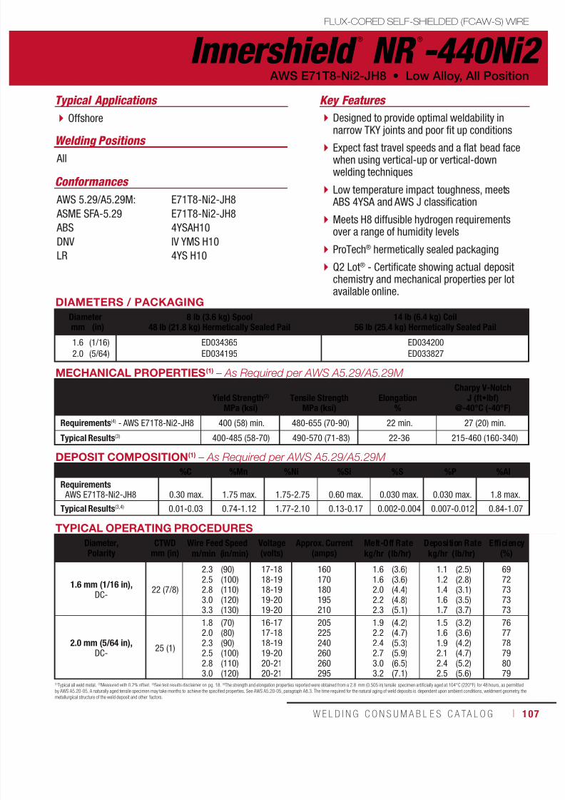
7/18/2019 c110 - Lincoln Electric Consumables 2014
http://slidepdf.com/reader/full/c110-lincoln-electric-consumables-2014 107/511W E L D I N G C O N S U M A B L E S C A TA L O G ı 107
MECHANICAL PROPERTIES(1) – As Required per AWS A5.29/A5.29M
Yield Strength(2)
MPa (ksi)
Tensile Strength
MPa (ksi)
Elongation
%
Charpy V-NotchJ (ft•lbf)
@-40°C (-40°F)Requirements(4) - AWS E71T8-Ni2-JH8 400 (58) min. 480-655 (70-90) 22 min. 27 (20) min.
Typical Results(3) 400-485 (58-70) 490-570 (71-83) 22-36 215-460 (160-340)
DEPOSIT COMPOSITION(1) – As Required per AWS A5.29/A5.29M
%C %Mn %Ni %Si %S %P %Al
Requirements AWS E71T8-Ni2-JH8 0.30 max. 1.75 max. 1.75-2.75 0.60 max. 0.030 max. 0.030 max. 1.8 max.
Typical Results(3,4) 0.01-0.03 0.74-1.12 1.77-2.10 0.13-0.17 0.002-0.004 0.007-0.012 0.84-1.07
(1)Typical all weld metal. (2)Measured with 0.2% offset. (3)See test results disclaimer on pg. 18. (4)The strength and elongation properties reported were obtained from a 2.8 mm (0.505 in) tensile specimen artificially aged at 104°C (220°F) for 48 hours, as permittedby AWS A5.20-05. A naturally aged tensile specimen may take months to achieve the specified properties. See AWS A5.20-05, paragraph A8.3. The time required for the natural aging of weld deposits is dependent upon ambient conditions, weldment geometry, the
metallurgical structure of the weld deposit and other factors.
TYPICAL OPERATING PROCEDURES
Diameter,Polarity CTWDmm (in) Wire Feed Speed Voltage(volts) Approx. Current(amps) Melt-Off Rate Deposition Rate Efficiency(%)m/min (in/min) kg/hr (lb/hr) kg/hr (lb/hr)
1.6 mm (1/16 in),DC-
22 (7/8)
2.32.52.83.03.3
(90)(100)(110)(120)(130)
17-1818-1918-1919-2019-20
160170180195210
1.61.62.02.22.3
(3.6)(3.6)(4.4)(4.8)(5.1)
1.11.21.41.61.7
(2.5)(2.8)(3.1)(3.5)(3.7)
6972737373
2.0 mm (5/64 in),DC-
25 (1)
1.82.02.32.52.83.0
(70)(80)(90)(100)(110)(120)
16-1717-1818-1919-2020-2120-21
205225240260260295
1.92.22.42.73.03.2
(4.2)(4.7)(5.3)(5.9)(6.5)(7.1)
1.51.61.92.12.42.5
(3.2)(3.6)(4.2)(4.7)(5.2)(5.6)
767778798079
Innershield ®
NR ®
-440Ni2FLUX-CORED SELF-SHIELDED (FCAW-S) WIRE
Welding Positions
Typical Applications
All
Offshore Designed to provide optimal weldability innarrow TKY joints and poor fit up conditions
Expect fast travel speeds and a flat bead facewhen using vertical-up or vertical-downwelding techniques
Low temperature impact toughness, meets ABS 4YSA and AWS J classification
Meets H8 diffusible hydrogen requirementsover a range of humidity levels
ProTech® hermetically sealed packaging
Q2 Lot® - Certificate showing actual depositchemistry and mechanical properties per lotavailable online.
Conformances
AWS E71T8-Ni2-JH8 • Low Alloy, All Position
Key Features
AWS 5.29/A5.29M:
ASME SFA-5.29
ABS
DNV
LR
E71T8-Ni2-JH8
E71T8-Ni2-JH8
4YSAH10
IV YMS H10
4YS H10
DIAMETERS / PACKAGING
Diameter 8 lb (3.6 kg) Spool48 lb (21.8 kg) Hermetically Sealed Pail
14 lb (6.4 kg) Coil56 lb (25.4 kg) Hermetically Sealed Pailmm (in)
1.62.0
(1/16)(5/64)
ED034365ED034195
ED034200ED033827

7/18/2019 c110 - Lincoln Electric Consumables 2014
http://slidepdf.com/reader/full/c110-lincoln-electric-consumables-2014 108/511108 ı T H E L I N C O L N E L E C T R I C C O M P A N Y
MECHANICAL PROPERTIES(1) – As Required per AWS A5.29/A5.29M
Yield Strength(2)
MPa (ksi)Tensile Strength
MPa (ksi)Elongation
%Hardness
Rockwell B
Charpy V-NotchJ (ft•lbf)
@ -29°C (-20°F)
Requirements(4) - AWS E71T8-K6 400 (58) min. 480-620 (70-90) 20 min. – 27 (20) min.
Typical Results(3) 415-445 (60-64) 520-545 (75-79) 29-33 84-87 81-237 (60-175)
DEPOSIT COMPOSITION(1) – As Required per AWS A5.29/A5.29M
%C %Mn %Si %S %P
Requirements - AWS E71T8-K6 0.15 max. 0.50-1.50 0.80 max. 0.030 max. 0.030 max.
Typical Results(3) 0.05-0.07 0.87-0.96 0.23-0.27 ≤0.003 0.004-0.008
%Ni %Cr %Mo %V %Al
Requirements - AWS E71T8-K6 0.40-1.00 0.20 max. 0.15 max. 0.05 max. 1.8 max.
Typical Results(3) 0.73-0.83 0.02-0.03 0.02-0.03 ≤0.01 0.9-1.1
(1)Typical all weld metal. (2)Measured with 0.2% offset. (3)See test results disclaimer on pg. 18.
TYPICAL OPERATING PROCEDURES
Diameter,Polarity
CTWDmm (in)
Wire Feed Speed Voltage(volts)
Approx. Current(amps)
Melt-Off Rate Deposition Rate Efficiency(%)m/min (in/min) kg/hr (lb/hr) kg/hr (lb/hr)
0.068 in (1.7 mm),
DC-25 (1)
2.02.63.03.54.4
(80)(105)(120)(140)(175)
17-1818-1919-2021-2221-22
190230245275295
1.72.22.53.03.6
(3.8)(5.3)(5.7)(6.8)(8.0)
1.31.82.02.42.9
(3.0)(4.0)(4.5)(5.5)(6.4)
7980798180
5/64 in (2.0 mm),
DC-25 (1)
1.72.02.22.73.3
(70)(80)(90)(110)(130)
17-1818-1918-1920-2120-21
205225240275300
2.02.32.63.13.7
(4.5)(5.1)(5.8)(7.0)(8.3)
1.51.72.02.42.9
(3.4)(3.9)(4.5)(5.5)(6.5)
7676787978
Innershield ®
NR ®
-207 FLUX-CORED SELF-SHIELDED (FCAW-S) WIRE
Welding Positions
Typical Applications
All
Standard cross-country pipelines
Arctic grade pipe up to undermatched X70
Vertical down hot, fill and cap passes onstandard cross-country pipelines and arcticgrade pipe
Recommended for API grades X42 up toundermatching X70
High deposition rates
Conformances
Low Alloy, All Position • AWS E71T8-K6
Key Features
AWS A5.29/A5.29M:
ASME SFA-A5.29:
ABS:
DNV Grade:
GL:
BV Grade:
E71T8-K6-H16
E71T8-K6-H16
E71T-8-K6
III YMS H15
3YH15S
SA3YMH
DIAMETERS / PACKAGING
Diameter 14 lb (6.4 kg) Coil56 lb (25.4 kg) Hermetically Sealed Pailin (mm)
0.0685/64
(1.7)(2.0)
ED016312ED012438

7/18/2019 c110 - Lincoln Electric Consumables 2014
http://slidepdf.com/reader/full/c110-lincoln-electric-consumables-2014 109/511W E L D I N G C O N S U M A B L E S C A TA L O G ı 109
Innershield ®
NR ®
-208-HFLUX-CORED SELF-SHIELDED (FCAW-S) WIRE
Welding Positions
Typical Applications
All, except vertical up
Standard cross-country pipelines
Undermatched X80 grade pipe
Designed to create high strength welddeposits
Recommended for API grade X80
High deposition rates
Conformances
AWS E91T8-G-H8 • Low Alloy, All Position
Key Features
AWS A5.29/A5.29M:
ASME SFA-A5.29:
E91T8-G-H8
E91T8-G-H8
DIAMETERS / PACKAGINGDiameter 14 lb (6.4 kg) Coil
56 lb (25.4 kg) Hermetically Sealed Pailin (mm)
5/64 (2.0) ED023366
TYPICAL OPERATING PROCEDURES
Diameter,Polarity
CTWDmm (in)
Wire Feed Speed Voltage(volts)
Approx. Current(amps)
Melt-Off Rate Deposition Rate Efficiency(%)m/min (in/min) kg/hr (lb/hr) kg/hr (lb/hr)
5/64 in (2.0 mm),
DC-25 (1)
1.72.02.22.73.3
(70)(80)(90)(110)(130)
16-1717-1818-1919-2019-20
195220235270295
1.82.12.52.93.5
(4.0)(4.6)(5.4)(6.5)(7.6)
1.41.72.02.42.9
(3.2)(3.9)(4.5)(5.5)(6.5)
8184848585
(1)Typical all weld metal. (2)Measured with 0.2% offset. (3)See test results disclaimer on pg. 18. (4)In order to meet the alloy requirements of the G group, the weld deposit needs to have the minimum, as specified in the table, of only one of the elements marked.
MECHANICAL PROPERTIES(1) – As Required per AWS A5.29/A5.29M
Yield Strength(2)
MPa (ksi)Tensile Strength
MPa (ksi)Elongation
%Hardness
Rockwell B
Charpy V-NotchJ (ft•lbf)
@ -29°C (-20°F)
Requirements - AWS E91T8-G-H8 540 (78) min. 620-760 (90-110) 17 min. – Not Specified
Typical Results(3) - As-Welded 555-600 (81-87) 630-670 (91-97) 24-27 91-95 54-129 (40-95)
DEPOSIT COMPOSITION(1) – As Required per AWS A5.29/A5.29M
%C %Mn %Si %S %P %Ni(4)
Requirements - AWS E91T8-G-H8 Not Specified 0.50 min. 1.00 max. 0.030 max. 0.030 max. 0.50 min.
Typical Results(3) 0.04-0.07 1.48-2.02 0.11-0.31 ≤0.003 0.004-0.010 0.71-0.98
%Cr(4) %Mo(4) %V(4) %Al(4)
Diffusible Hydrogen(mL/100g weld metal)
Requirements - AWS E91T8-G-H8 0.30 min. 0.20 max. 0.10 min. 1.8 min. 8.0 max.
Typical Results(3) 0.02-0.03 ≤0.04 ≤0.01 0.9-1.2 ≤8

7/18/2019 c110 - Lincoln Electric Consumables 2014
http://slidepdf.com/reader/full/c110-lincoln-electric-consumables-2014 110/511110 ı T H E L I N C O L N E L E C T R I C C O M P A N Y
UltraCore ®
71A85
Welding Positions
Typical Applications
All
Shipbuilding
Seismic structural fabrication
General fabrication
Designed for welding with 75 - 85% Argon/balance CO
2 shielding gas
Premium arc performance and beadappearance
Meets AWS D1.8 seismic lot waiverrequirements
Conformances
Shielding Gas
75% - 85% Argon / Balance CO2
Flow Rate: 40 - 50 CFH
Mild Steel, All Position • AWS E71T-1M, E71T-9M
Key Features
AWS A5.20/A5.20M:
ASME SFA-A5.20: ABS:
Lloyd’s Register:
DNV Grade:
CWB/CSA W48-06:
EN ISO 17632-B:
FEMA 353 AWS D1.8
E71T-1M, E71T-9M
E71T-1M, E71T-9M3YSA H10
3YS H10
III YMS H10
E491T-9M H8
T493T1-1MA-H10
DIAMETERS / PACKAGING
Diameter 15 lb (6.8 kg) Plastic Spool60 lb (27.2 kg) Master Carton
33 lb (15 kg)Spool*
50 lb (22.7 kg)Fiber Spool
500 lb (227 kg)Accu-Trak ® Drumin (mm)
0.0450.0521/16
(1.1)(1.3)(1.6)
ED031885ED031886ED031887
ED031663ED031664ED031665
ED031847ED031848ED031849
ED032047ED032048ED032049
MECHANICAL PROPERTIES(1) – As Required per AWS A5.20/A5.20M
Yield Strength(2) Tensile Strength ElongationCharpy V-Notch
J (ft•lbf)
MPa (ksi) MPa (ksi) % @ -18°C (0°F) @ -29°C (-20°F)
Requirements(4)
AWS E71T-1M AWS E71T-9M
400 (58)
min.
480-655(70-95)
22
min.27 (20) min. Not Specified
Not Specified 27 (20) min.
Typical Results(3)
As-Welded with 75%-85% Ar/balance CO2 550-600 (80-88) 600-650 (87-94) 24 - 26 64-115 (47-85) 43-95 (32-70)
FLUX-CORED GAS-SHIELDED (FCAW-G) WIREuctural Welding Code
smic Supplement
*Spool may be plastic or fiber.
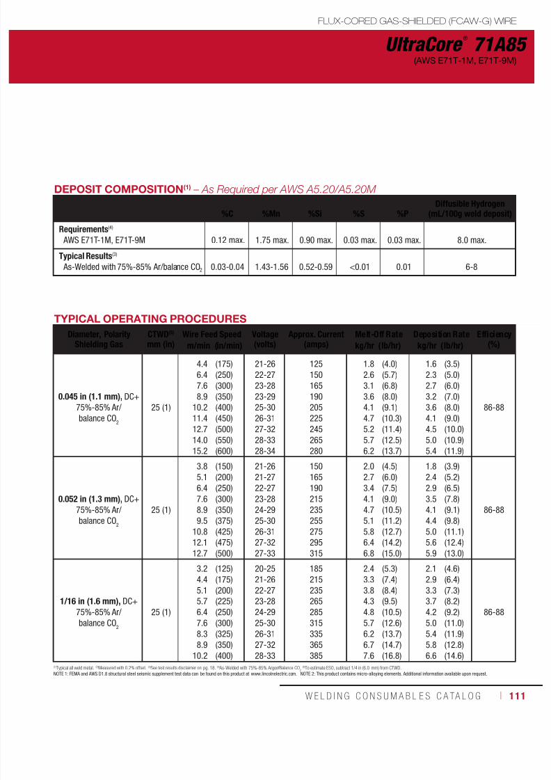
7/18/2019 c110 - Lincoln Electric Consumables 2014
http://slidepdf.com/reader/full/c110-lincoln-electric-consumables-2014 111/511W E L D I N G C O N S U M A B L E S C A TA L O G ı 111
UltraCore ®
71A85(AWS E71T-1M, E71T-9M)
DEPOSIT COMPOSITION(1) – As Required per AWS A5.20/A5.20M
%C
%Mn
%Si
%S
%P
Diffusible Hydrogen(mL/100g weld deposit)
Requirements(4)
AWS E71T-1M, E71T-9M 0.12 max. 1.75 max. 0.90 max. 0.03 max. 0.03 max. 8.0 max.
Typical Results(3)
As-Welded with 75%-85% Ar/balance CO2 0.03-0.04 1.43-1.56 0.52-0.59 <0.01 0.01 6-8
TYPICAL OPERATING PROCEDURES
Diameter, PolarityShielding Gas
CTWD(5)
mm (in)Wire Feed Speed Voltage
(volts)Approx. Current
(amps)Melt-Off Rate Deposition Rate Efficiency
(%)m/min (in/min) kg/hr (lb/hr) kg/hr (lb/hr)
0.045 in (1.1 mm), DC+75%-85% Ar/balance CO
2
25 (1)
4.46.47.6
8.910.211.412.714.015.2
(175)(250)(300)
(350)(400)(450)(500)(550)(600)
21-2622-2723-28
23-2925-3026-3127-3228-3328-34
125150165
190205225245265280
1.82.63.1
3.64.14.75.25.76.2
(4.0)(5.7)(6.8)
(8.0)(9.1)(10.3)(11.4)(12.5)(13.7)
1.62.32.7
3.23.64.14.55.05.4
(3.5)(5.0)(6.0)
(7.0)(8.0)(9.0)(10.0)(10.9)(11.9)
86-88
0.052 in (1.3 mm), DC+75%-85% Ar/balance CO
2
25 (1)
3.85.16.47.68.99.5
10.812.112.7
(150)(200)(250)(300)(350)(375)
(425)(475)(500)
21-2621-2722-2723-2824-2925-30
26-3127-3227-33
150165190215235255
275295315
2.02.73.44.14.75.1
5.86.46.8
(4.5)(6.0)(7.5)(9.0)(10.5)(11.2)
(12.7)(14.2)(15.0)
1.82.42.93.54.14.4
5.05.65.9
(3.9)(5.2)(6.5)(7.8)(9.1)(9.8)
(11.1)(12.4)(13.0)
86-88
1/16 in (1.6 mm), DC+75%-85% Ar/balance CO
2
25 (1)
3.24.45.15.76.47.68.38.9
10.2
(125)(175)(200)(225)(250)(300)(325)(350)(400)
20-2521-2622-2723-2824-2925-3026-3127-3228-33
185215235265285315335365385
2.43.33.84.34.85.76.26.77.6
(5.3)(7.4)(8.4)(9.5)(10.5)(12.6)(13.7)(14.7)(16.8)
2.12.93.33.74.25.05.45.86.6
(4.6)(6.4)(7.3)(8.2)(9.2)(11.0)(11.9)(12.8)(14.6)
86-88
(1)Typical all weld metal. (2)Measured with 0.2% offset. (3)See test results disclaimer on pg. 18. (4) As-Welded with 75%-85% Argon/Balance CO2(5)To estimate ESO, subtract 1/4 in (6.0 mm) from CTWD.
NOTE 1: FEMA and AWS D1.8 structural steel seismic supplement test data can be found on this product at www.lincolnelectric.com. NOTE 2: This product contains micro-alloying elements. Additional information available upon request.
FLUX-CORED GAS-SHIELDED (FCAW-G) WIRE
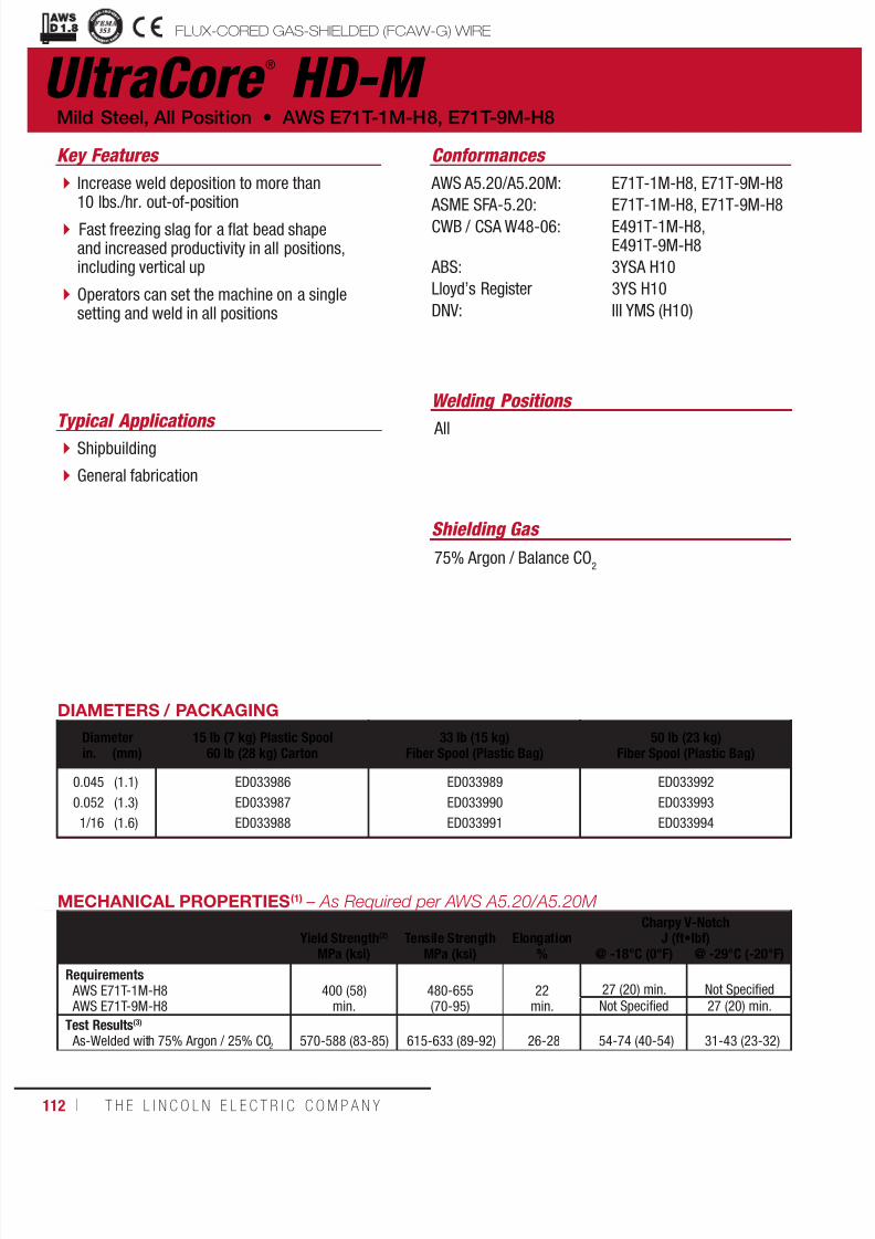
7/18/2019 c110 - Lincoln Electric Consumables 2014
http://slidepdf.com/reader/full/c110-lincoln-electric-consumables-2014 112/511112 ı T H E L I N C O L N E L E C T R I C C O M P A N Y
UltraCore ®
HD-M
Welding Positions
Typical Applications All Shipbuilding
General fabrication
Increase weld deposition to more than10 lbs./hr. out-of-position
Fast freezing slag for a flat bead shapeand increased productivity in all positions,including vertical up
Operators can set the machine on a singlesetting and weld in all positions
Conformances
Shielding Gas
75% Argon / Balance CO2
Mild Steel, All Position • AWS E71T-1M-H8, E71T-9M-H8
Key Features
AWS A5.20/A5.20M:
ASME SFA-5.20:CWB / CSA W48-06:
ABS:
Lloyd’s Register
DNV:
E71T-1M-H8, E71T-9M-H8
E71T-1M-H8, E71T-9M-H8E491T-1M-H8,E491T-9M-H8
3YSA H10
3YS H10
III YMS (H10)
FLUX-CORED GAS-SHIELDED (FCAW-G) WIREuctural Welding Code
smic Supplement
DIAMETERS / PACKAGING
Diameter 15 lb (7 kg) Plastic Spool60 lb (28 kg) Carton
33 lb (15 kg)Fiber Spool (Plastic Bag)
50 lb (23 kg)Fiber Spool (Plastic Bag)in. (mm)
0.045
0.052
1/16
(1.1)
(1.3)
(1.6)
ED033986
ED033987
ED033988
ED033989
ED033990
ED033991
ED033992
ED033993
ED033994
MECHANICAL PROPERTIES(1) – As Required per AWS A5.20/A5.20M
Yield Strength(2) Tensile Strength ElongationCharpy V-Notch
J (ft•lbf)MPa (ksi) MPa (ksi) % @ -18°C (0°F) @ -29°C (-20°F)
Requirements AWS E71T-1M-H8 AWS E71T-9M-H8
400 (58)min.
480-655(70-95)
22min.
27 (20) min. Not SpecifiedNot Specified 27 (20) min.
Test Results(3)
As-Welded with 75% Argon / 25% CO2 570-588 (83-85) 615-633 (89-92) 26-28 54-74 (40-54) 31-43 (23-32)
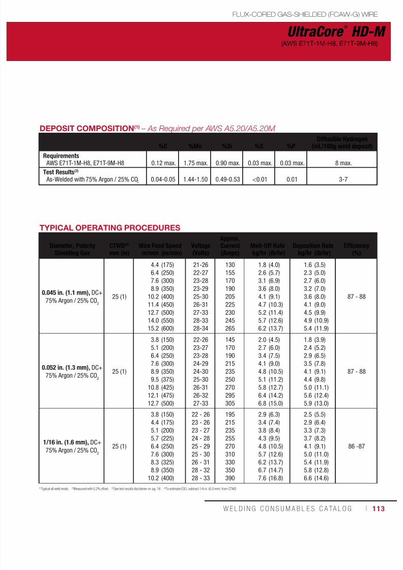
7/18/2019 c110 - Lincoln Electric Consumables 2014
http://slidepdf.com/reader/full/c110-lincoln-electric-consumables-2014 113/511W E L D I N G C O N S U M A B L E S C A TA L O G ı 113
UltraCore ®
HD-M(AWS E71T-1M-H8, E71T-9M-H8)
FLUX-CORED GAS-SHIELDED (FCAW-G) WIRE
DEPOSIT COMPOSITION(1) – As Required per AWS A5.20/A5.20M
%C %Mn %Si %S %PDiffusible Hydrogen
(mL/100g weld deposit)
Requirements AWS E71T-1M-H8, E71T-9M-H8 0.12 max. 1.75 max. 0.90 max. 0.03 max. 0.03 max. 8 max.
Test Results(3)
As-Welded with 75% Argon / 25% CO2 0.04-0.05 1.44-1.50 0.49-0.53 <0.01 0.01 3-7
TYPICAL OPERATING PROCEDURES
Diameter, Polarity
Shielding Gas
CTWD(4)
mm (in)
Wire Feed Speed
Voltage(Volts)
Approx.Current(Amps)
Melt-Off Rate
Deposition Rate
Efficiency
(%)m/min (in/min) kg/hr (lb/hr) kg/hr (lb/hr)
0.045 in. (1.1 mm), DC+75% Argon / 25% CO
2
25 (1)
4.46.47.68.9
10.211.412.714.015.2
(175)(250)(300)(350)(400)(450)(500)(550)(600)
21-2622-2723-2823-2925-3026-3127-3328-3328-34
130155170190205225230245265
1.82.63.13.64.14.75.25.76.2
(4.0)(5.7)(6.9)(8.0)(9.1)(10.3)(11.4)(12.6)(13.7)
1.62.32.73.23.64.14.54.95.4
(3.5)(5.0)(6.0)(7.0)(8.0)(9.0)(9.9)(10.9)(11.9)
87 - 88
0.052 in. (1.3 mm), DC+75% Argon / 25% CO
2
25 (1)
3.85.16.47.68.99.5
10.812.112.7
(150)(200)(250)(300)(350)(375)
(425)(475)(500)
22-2623-2723-2824-2924-3025-30
26-3126-3227-33
145170190215235250
270295305
2.02.73.44.14.85.1
5.86.46.8
(4.5)(6.0)(7.5)(9.0)(10.5)(11.2)
(12.7)(14.2)(15.0)
1.82.42.93.54.14.4
5.05.65.9
(3.9)(5.2)(6.5)(7.8)(9.1)(9.8)
(11.1)(12.4)(13.0)
87 - 88
1/16 in. (1.6 mm), DC+75% Argon / 25% CO
2
25 (1)
3.84.45.15.76.47.68.38.9
10.2
(150)(175)(200)(225)(250)(300)(325)(350)(400)
22 - 2623 - 2623 - 2724 - 2825 - 2925 - 3026 - 3128 - 3228 - 33
195215235255270310330350390
2.93.43.84.34.85.76.26.77.6
(6.3)(7.4)(8.4)(9.5)(10.5)(12.6)(13.7)(14.7)(16.8)
2.52.93.33.74.15.05.45.86.6
(5.5)(6.4)(7.3)(8.2)(9.1)(11.0)(11.9)(12.8)(14.6)
86 -87
(1)Typical all weld metal. (2)Measured with 0.2% offset. (3)See test results disclaimer on pg. 18. (4)To estimate ESO, subtract 1/4 in. (6.0 mm) from CTWD.
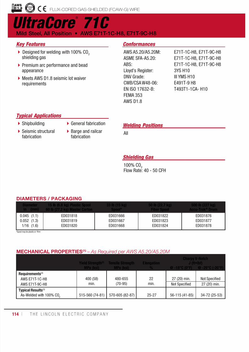
7/18/2019 c110 - Lincoln Electric Consumables 2014
http://slidepdf.com/reader/full/c110-lincoln-electric-consumables-2014 114/511114 ı T H E L I N C O L N E L E C T R I C C O M P A N Y
uctural Welding Code
smic Supplement
UltraCore ®
71C
Welding Positions
Typical Applications
All
Shipbuilding
Seismic structuralfabrication
General fabrication
Barge and railcarfabrication
Designed for welding with 100% CO2
shielding gas
Premium arc performance and beadappearance
Meets AWS D1.8 seismic lot waiverrequirements
Conformances
Shielding Gas
100% CO2
Flow Rate: 40 - 50 CFH
Mild Steel, All Position • AWS E71T-1C-H8, E71T-9C-H8
Key Features
AWS A5.20/A5.20M:
ASME SFA-A5.20: ABS:
Lloyd’s Register:
DNV Grade:
CWB/CSA W48-06:
EN ISO 17632-B:
FEMA 353
AWS D1.8
E71T-1C-H8, E71T-9C-H8
E71T-1C-H8, E71T-9C-H8E71T-1C-H8, E71T-9C-H8
3YS H10
III YMS H10
E491T-9 H8
T493T1-1CA- H10
DIAMETERS / PACKAGING
Diameter 15 lb (6.8 kg) Plastic Spool60 lb (27.2 kg) Master Carton
33 lb (15 kg)Spool*
50 lb (22.7 kg)Fiber Spool
500 lb (227 kg)Accu-Trak ® Drumin (mm)
0.0450.0521/16
(1.1)(1.3)(1.6)
ED031818ED031819ED031820
ED031666ED031667ED031668
ED031822ED031823ED031824
ED031876ED031877ED031878
MECHANICAL PROPERTIES(1) – As Required per AWS A5.20/A5.20M
Yield Strength(2) Tensile Strength ElongationCharpy V-Notch
J (ft•lbf)
MPa (ksi) MPa (ksi) % @ -18°C (0°F) @ -29°C (-20°F)
Requirements(4)
AWS E71T-1C-H8
AWS E71T-9C-H8
400 (58)
min.
480-655(70-95)
22
min.
27 (20) min.
Not Specified
Not Specified 27 (20) min.
Typical Results(3)
As-Welded with 100% CO2
515-560 (74-81) 570-605 (82-87) 25-27 56-115 (41-85) 34-72 (25-53)
FLUX-CORED GAS-SHIELDED (FCAW-G) WIRE
*Spool may be plastic or fiber.
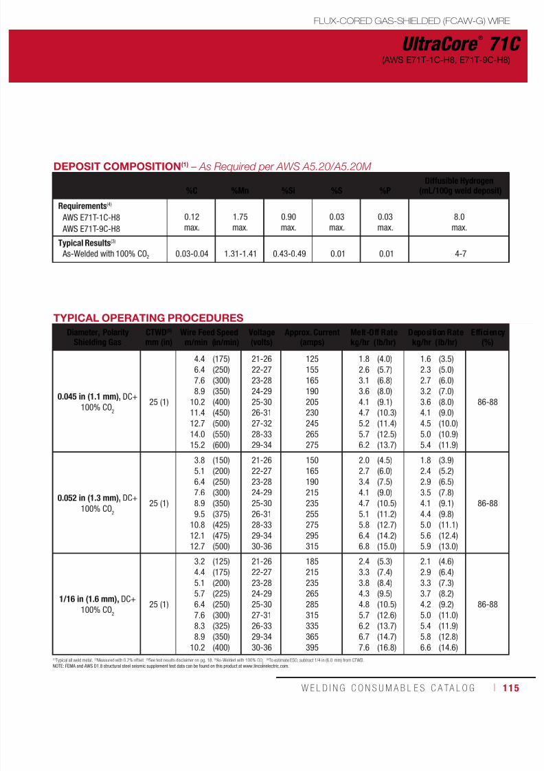
7/18/2019 c110 - Lincoln Electric Consumables 2014
http://slidepdf.com/reader/full/c110-lincoln-electric-consumables-2014 115/511W E L D I N G C O N S U M A B L E S C A TA L O G ı 115
FLUX-CORED GAS-SHIELDED (FCAW-G) WIRE
UltraCore ®
71C(AWS E71T-1C-H8, E71T-9C-H8)
DEPOSIT COMPOSITION(1) – As Required per AWS A5.20/A5.20M
%C %Mn %Si %S %PDiffusible Hydrogen
(mL/100g weld deposit)
Requirements(4)
AWS E71T-1C-H8
AWS E71T-9C-H8
0.12max.
1.75max.
0.90max.
0.03max.
0.03max.
8.0max.
Typical Results(3)
As-Welded with 100% CO2 0.03-0.04 1.31-1.41 0.43-0.49 0.01 0.01 4-7
TYPICAL OPERATING PROCEDURES
Diameter, PolarityShielding Gas
CTWD(5)
mm (in)Wire Feed Speed Voltage
(volts)Approx. Current
(amps)Melt-Off Rate Deposition Rate Efficiency
(%)m/min (in/min) kg/hr (lb/hr) kg/hr (lb/hr)
0.045 in (1.1 mm), DC+100% CO
2
25 (1)
4.46.47.6
8.910.211.412.714.015.2
(175)(250)(300)
(350)(400)(450)(500)(550)(600)
21-2622-2723-28
24-2925-3026-3127-3228-3329-34
125155165
190205230245265275
1.82.63.1
3.64.14.75.25.76.2
(4.0)(5.7)(6.8)
(8.0)(9.1)(10.3)(11.4)(12.5)(13.7)
1.62.32.7
3.23.64.14.55.05.4
(3.5)(5.0)(6.0)
(7.0)(8.0)(9.0)(10.0)(10.9)(11.9)
86-88
0.052 in (1.3 mm), DC+100% CO
2
25 (1)
3.85.16.47.68.99.5
10.812.112.7
(150)(200)(250)(300)(350)(375)
(425)(475)(500)
21-2622-2723-2824-2925-3026-31
28-3329-3430-36
150165190215235255
275295315
2.02.73.44.14.75.1
5.86.46.8
(4.5)(6.0)(7.5)(9.0)(10.5)(11.2)
(12.7)(14.2)(15.0)
1.82.42.93.54.14.4
5.05.65.9
(3.9)(5.2)(6.5)(7.8)(9.1)(9.8)
(11.1)(12.4)(13.0)
86-88
1/16 in (1.6 mm), DC+100% CO
2
25 (1)
3.24.45.15.76.47.68.38.9
10.2
(125)(175)(200)(225)(250)(300)(325)(350)(400)
21-2622-2723-2824-2925-3027-3126-3329-3430-36
185215235265285315335365395
2.43.33.84.34.85.76.26.77.6
(5.3)(7.4)(8.4)(9.5)(10.5)(12.6)(13.7)(14.7)(16.8)
2.12.93.33.74.25.05.45.86.6
(4.6)(6.4)(7.3)(8.2)(9.2)(11.0)(11.9)(12.8)(14.6)
86-88
(1)Typical all weld metal. (2)Measured with 0.2% offset. (3)See test results disclaimer on pg. 18. (4) As-Welded with 100% CO2(5)To estimate ESO, subtract 1/4 in (6.0 mm) from CTWD.
NOTE: FEMA and AWS D1.8 structural steel seismic supplement test data can be found on this product at www.lincolnelectric.com.

7/18/2019 c110 - Lincoln Electric Consumables 2014
http://slidepdf.com/reader/full/c110-lincoln-electric-consumables-2014 116/511116 ı T H E L I N C O L N E L E C T R I C C O M P A N Y
UltraCore ®
HD-C Mild Steel, All Position • AWS E71T-1C-H8, E71T-9C-H8
FLUX-CORED GAS-SHIELDED (FCAW-G) WIRE
Welding Positions
Typical Applications
All
Shipbuilding
General fabrication
High deposition rates, increase weld depositionup to 10 lbs/hr out-of-position
Fast freezing slag for a flat bead shape andincreased productivity in all positions, includingvertical up
Operators can set the machine on a singlesetting and weld in all positions
Little or no pre-weld clean up required, weldover light rust, mill scale, and primer
Conformances
Shielding Gas
100% CO2
Flow Rate: 40 - 50 CFH
Key Features
AWS 5.20/A5.20M:
ABS:Lloyd’s Register:
DNV:
CWB/CSA W48-06:
E71T-1C-H8, E71T-9C-H8
3YSA H103YS H10
III YMS H10
E491T-9-H8
DIAMETERS / PACKAGING
Diameter 15 lb (6.8 kg) Plastic Spool60 lb (27.2 kg) Master Carton
33 lb (15 kg)Spool*
50 lb (22.7 kg)Fiber Spool
500 lb (227 kg)Accu-Trak ® Drumin. (mm)
0.0450.0521/16
(1.1)(1.3)(1.6)
ED033756ED033759ED033762
ED033755ED033758ED033761
ED033757ED033760ED033763 ED033785
MECHANICAL PROPERTIES(1) – As Required per AWS A5.20/A5.20M
Yield Strength(2) Tensile Strength ElongationCharpy V-Notch
J (ft•lbf)MPa (ksi) MPa (ksi) % @ -18°C (0°F) @ -29°C (-20°F)
Requirements
AWS E71T-1C-H8 AWS E71T-9C-H8
400 (58)min.
480-660 (70-95)
22min.
27 (20) min. Not Specified
Not Specified 27 (20) min.
Test Results(3) - As-Welded with 100% CO2 540-560 (78-81) 590-610 (86-89) 27 37-111 (27-82) 31-85 (23-63)
*Spool may be plastic or fiber.
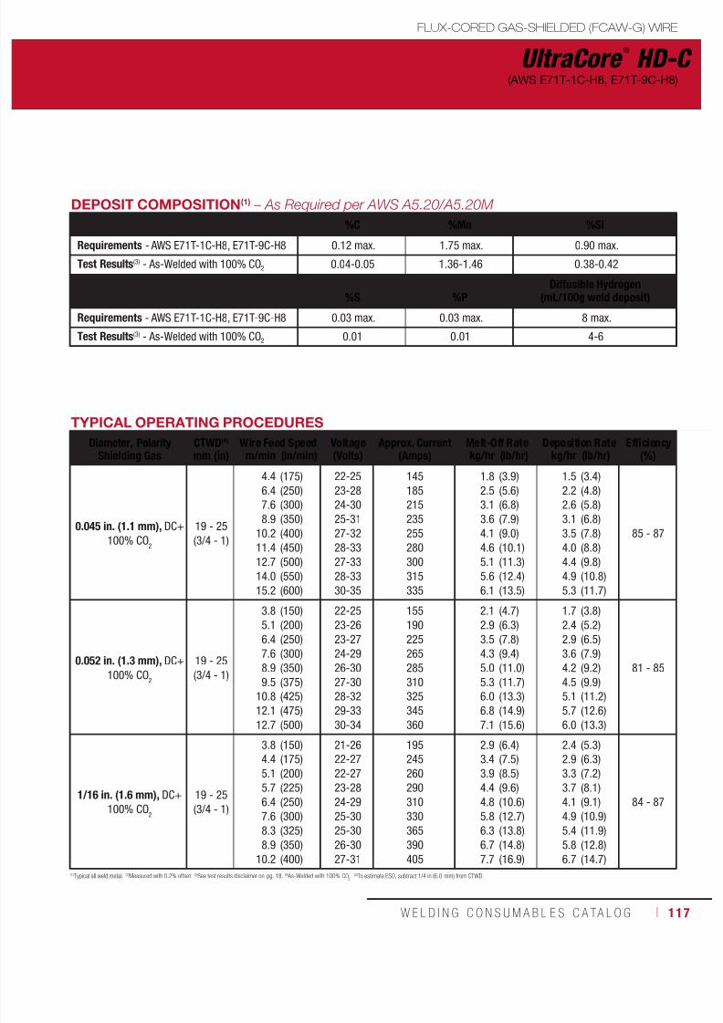
7/18/2019 c110 - Lincoln Electric Consumables 2014
http://slidepdf.com/reader/full/c110-lincoln-electric-consumables-2014 117/511W E L D I N G C O N S U M A B L E S C A TA L O G ı 117
FLUX-CORED GAS-SHIELDED (FCAW-G) WIRE
UltraCore ®
HD-C(AWS E71T-1C-H8, E71T-9C-H8)
(1)Typical all weld metal. (2)Measured with 0.2% offset. (3)See test results disclaimer on pg. 18. (4) As-Welded with 100% CO2(5)To estimate ESO, subtract 1/4 in (6.0 mm) from CTWD.
DEPOSIT COMPOSITION(1) – As Required per AWS A5.20/A5.20M
%C %Mn %Si
Requirements - AWS E71T-1C-H8, E71T-9C-H8 0.12 max. 1.75 max. 0.90 max.
Test Results(3) - As-Welded with 100% CO2 0.04-0.05 1.36-1.46 0.38-0.42
%S %PDiffusible Hydrogen
(mL/100g weld deposit)
Requirements - AWS E71T-1C-H8, E71T-9C-H8 0.03 max. 0.03 max. 8 max.
Test Results(3) - As-Welded with 100% CO2 0.01 0.01 4-6
TYPICAL OPERATING PROCEDURES
Diameter, PolarityShielding Gas
CTWD(4)
mm (in)Wire Feed Speed Voltage
(Volts)Approx. Current
(Amps)Melt-Off Rate Deposition Rate Efficiency
(%)m/min (in/min) kg/hr (lb/hr) kg/hr (lb/hr)
0.045 in. (1.1 mm), DC+100% CO
2
19 - 25(3/4 - 1)
4.46.47.6
8.910.211.412.714.015.2
(175)(250)(300)
(350)(400)(450)(500)(550)(600)
22-2523-2824-30
25-3127-3228-3327-3328-3330-35
145185215
235255280300315335
1.82.53.1
3.64.14.65.15.66.1
(3.9)(5.6)(6.8)
(7.9)(9.0)(10.1)(11.3)(12.4)(13.5)
1.52.22.6
3.13.54.04.44.95.3
(3.4)(4.8)(5.8)
(6.8)(7.8)(8.8)(9.8)(10.8)(11.7)
85 - 87
0.052 in. (1.3 mm), DC+100% CO
2
19 - 25(3/4 - 1)
3.85.16.47.68.99.5
10.812.112.7
(150)(200)(250)(300)(350)(375)
(425)(475)(500)
22-2523-2623-2724-2926-3027-30
28-3229-3330-34
155190225265285310
325345360
2.12.93.54.35.05.3
6.06.87.1
(4.7)(6.3)(7.8)(9.4)(11.0)(11.7)
(13.3)(14.9)(15.6)
1.72.42.93.64.24.5
5.15.76.0
(3.8)(5.2)(6.5)(7.9)(9.2)(9.9)
(11.2)(12.6)(13.3)
81 - 85
1/16 in. (1.6 mm), DC+100% CO
2
19 - 25(3/4 - 1)
3.84.45.15.76.47.68.38.9
10.2
(150)(175)(200)(225)(250)(300)(325)(350)(400)
21-2622-2722-2723-2824-2925-3025-3026-3027-31
195245260290310330365390405
2.93.43.94.44.85.86.36.77.7
(6.4)(7.5)(8.5)(9.6)(10.6)(12.7)(13.8)(14.8)(16.9)
2.42.93.33.74.14.95.45.86.7
(5.3)(6.3)(7.2)(8.1)(9.1)(10.9)(11.9)(12.8)(14.7)
84 - 87

7/18/2019 c110 - Lincoln Electric Consumables 2014
http://slidepdf.com/reader/full/c110-lincoln-electric-consumables-2014 118/511118 ı T H E L I N C O L N E L E C T R I C C O M P A N Y
UltraCore ®
71A75 Dual FLUX-CORED GAS-SHIELDED (FCAW-G) WIRE
Welding Positions
Typical Applications
All
General fabrication
Designed for welding with either 100% CO2
or 75% Argon/25% CO2 shielding gases
Premium arc performance and beadappearance
Conformances
Shielding Gas
100% CO2
75% Argon / 25% CO2
Flow Rate: 40 - 50 CFH
Mild Steel, All Position • AWS E71T-1C-H8, E71T-9C-H8, E71T-1M-H8, E71T-9M-H8
Key Features
AWS A5.20/A5.20M:
ASME SFA-A5.20:
CWB/CSA W48-06:
EN ISO 17632-B:
E71T-1C-H8, E71T-1M-H8,
E71T-9C-H8, E71T-9M-H8
E71T-1C-H8, E71T-1M-H8,E71T-9C-H8, E71T-9M-H8
E491T-9 H8, E491T-9M H8
T493T1-1MA-H10,T493T1-1CA-H10
DIAMETERS / PACKAGING
Diameter 15 lb (6.8 kg) Plastic Spool60 lb (27.2 kg) Master Carton
33 lb (15 kg)Spool*
50 lb (22.7 kg)Fiber Spool
500 lb (227 kg)Accu-Trak ® Drumin (mm)
0.0450.0521/16
(1.1)(1.3)(1.6)
ED031882 ED031669ED031670ED031671
ED031844ED031845ED031846
ED032044
ED032046
MECHANICAL PROPERTIES(1) – As Required per AWS A5.20/A5.20M
YieldStrength(2)
TensileStrength Elongation
Charpy V-NotchJ (ft•lbf)
MPa (ksi) MPa (ksi) % @ -18°C (0°F) @ -29°C (-20°F)
Requirements(4)
AWS E71T-1C-H8, E71T-1M-H8
AWS E71T-9C-H8, E71T-9M-H8
400 (58)min.
480-655(70-95)
22
min.27 (20) min. Not Specified
Not Specified 27 (20) min.
Typical Results(3)
As-Welded with 100% CO2
As-Welded with 75% Ar/25% CO2
510-550 (73-79)570-610 (82-88)
570-600 (82-87)620-660 (89-95)
26-2824-26
38-95 (28-70)62-111 (46-82)
27-65 (20-48)39-85 (29-63)
*Spool may be plastic or fiber.

7/18/2019 c110 - Lincoln Electric Consumables 2014
http://slidepdf.com/reader/full/c110-lincoln-electric-consumables-2014 119/511W E L D I N G C O N S U M A B L E S C A TA L O G ı 119
UltraCore ®
71A75 Dual
FLUX-CORED GAS-SHIELDED (FCAW-G) WIRE
(AWS E71T-1C-H8, E71T-1M-H8, E71T-9C-H8, E71T-9M-H8)
DEPOSIT COMPOSITION(1) – As Required per AWS A5.20/A5.20M
%C %Mn %Si %S %PDiffusible Hydrogen
(mL/100g weld deposit)
Requirements(4)
AWS E71T-1C-H8, E71T-1M-H8 AWS E71T-9C-H8, E71T-9M-H8
0.12max.
1.75max.
0.90max.
0.03max.
0.03max.
8.0max.
Typical Results(3)
As-Welded with 100% CO2
As-Welded with 75% Ar/25% CO2
0.03-0.04
0.03-0.04
1.28-1.41
1.45-1.60
0.42-0.49
0.54-0.62
0.01
0.01
0.01-0.02
0.01-0.02
3-8
4-8
TYPICAL OPERATING PROCEDURES
Diameter, PolarityShielding Gas(5)
CTWD(6)
mm (in)Wire Feed Speed Voltage
(volts)Approx. Current
(amps)Melt-Off Rate Deposition Rate Efficiency
(%)m/min (in/min) kg/hr (lb/hr) kg/hr (lb/hr)
0.045 in (1.1 mm), DC+ 75% Ar/25% CO
2
25 (1)
4.46.47.6
8.910.211.412.714.015.2
(175)(250)(300)
(350)(400)(450)(500)(550)(600)
20-2521-2622-27
23-2824-2925-3026-3127-3227-33
135150165
190205225245265285
1.82.63.1
3.64.14.75.25.76.2
(4.0)(5.7)(6.8)
(8.0)(9.1)(10.3)(11.4)(12.5)(13.7)
1.62.32.7
3.23.64.14.55.05.4
(3.5)(5.0)(6.0)
(7.0)(8.0)(9.0)(10.0)(10.9)(11.9)
86-88
0.052 in (1.3 mm), DC+ 75% Ar/25% CO
2
25 (1)
3.85.16.47.68.99.5
10.812.112.7
(150)(200)(250)(300)(350)(375)
(425)(475)(500)
20-2521-2622-2723-2824-2925-30
27-3128-3329-35
155165190215235255
275295325
2.02.73.44.14.75.1
5.86.46.8
(4.5)(6.0)(7.5)(9.0)(10.5)(11.2)
(12.7)(14.2)(15.0)
1.82.42.93.54.14.4
5.05.65.9
(3.9)(5.2)(6.5)(7.8)(9.1)(9.8)
(11.1)(12.4)(13.0)
86-88
1/16 in (1.6 mm), DC+ 75% Ar/25% CO
2
25 (1)
3.24.45.15.76.47.68.38.9
10.2
(125)(175)(200)(225)(250)(300)(325)(350)(400)
20-2521-2622-2723-2824-2925-3125-3226-3328-35
195215235265285315335365405
2.43.33.84.34.85.76.26.77.6
(5.3)(7.4)(8.4)(9.5)(10.5)(12.6)(13.7)(14.7)(16.8)
2.12.93.33.74.25.05.45.86.6
(4.6)(6.4)(7.3)(8.2)(9.2)(11.0)(11.9)(12.8)(14.6)
86-88
(1)Typical all weld metal. (2)Measured with 0.2% offset. (3)See test results disclaimer on pg. 18. (4) As-Welded with 100% CO2 & As-Welded 75% Argon / 25% CO2. (5) When welding under CO2, increase voltage by 1 Volt. (6)To estimate ESO, subtract 1/4 in (6.0 mm) from CTWD.NOTE: This product contains micro-alloying elements. Additional information available upon request.

7/18/2019 c110 - Lincoln Electric Consumables 2014
http://slidepdf.com/reader/full/c110-lincoln-electric-consumables-2014 120/511120 ı T H E L I N C O L N E L E C T R I C C O M P A N Y
UltraCore ®
712C FLUX-CORED GAS-SHIELDED (FCAW-G) WIRE
Welding Positions
Typical Applications
All
Bridge fabrication
Pressure vessels
Shipbuilding
Offshore
ASME relatedapplications
Capable of producing weld deposits withimpact toughness exceeding 27 J (20 ft•lbf)at -40°C (-40°F)
Designed for welding with 100% CO2
shielding gas
Premium arc performance and beadappearance
Conformances
Shielding Gas
100% CO2
Flow Rate: 40-50 CFH
Mild Steel, All Position • AWS E71T-1C-JH8, E71T-9C-JH8, E71T-12C-JH8
Key Features
AWS A5.20/A5.20M:
ASME SFA-A5.20:
ABS:
Lloyd’s Register:
DNV Grade:
CWB/CSA W48-06:
EN ISO 17632-B:
E71T-1C-JH8, E71T-9C-JH8,E71T-12C-JH8
E71T-1C-JH8, E71T-9C-JH8,E71T-12C-JH8
3YSA H10
3YS H10
III YMS H10
E491T-12J H8, E491T-9J H8
T494T12-1CA-K-H10
DIAMETERS / PACKAGING
Diameter 15 lb (6.8 kg) Plastic Spool60 lb (27.2 kg) Master Carton
33 lb (15 kg)Spool*
50 lb (22.7 kg)Fiber Spool
500 lb (227 kg)Accu-Trak ® Drumin (mm)
0.0450.0521/16
(1.1)(1.3)(1.6) ED031896
ED031672ED031673ED031674
ED031839ED031840
ED031681
ED031799
MECHANICAL PROPERTIES(1) – As Required per AWS A5.20/A5.20M
YieldStrength(2)
TensileStrength Elongation
Charpy V-NotchJ (ft•lbf)
MPa (ksi) MPa (ksi) % @ -18°C (0°F) @ -29°C (-20°F) @ -40°C (-40°F)
Requirements(4)
AWS E71T-1C-JH8 AWS E71T-9C-JH8
AWS E71T-12C-JH8
400 (58) min. 480-655 (70-95)
22 min.27 (20) min. Not Specified
27 (20) min.Not Specified 27 (20) min.
480-620 (70-90) Not Specified 27 (20) min.
Typical Results(3)
As-Welded with 100% CO2 485-535 (70-77) 540-585 (78-84) 25-28 135-193 (100-143) 91-164 (67-121) 57-133 (42-98)
*Spool may be plastic or fiber.
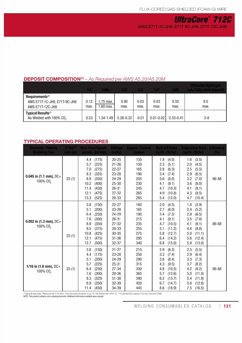
7/18/2019 c110 - Lincoln Electric Consumables 2014
http://slidepdf.com/reader/full/c110-lincoln-electric-consumables-2014 121/511W E L D I N G C O N S U M A B L E S C A TA L O G ı 121
UltraCore ®
712C
FLUX-CORED GAS-SHIELDED (FCAW-G) WIRE
(AWS E71T-1C-JH8, E71T-9C-JH8, E71T-12C-JH8)
DEPOSIT COMPOSITION(1) – As Required per AWS A5.20/A5.20M
%C %Mn %Si %S %P %NiDiffusible Hydrogen
(mL/100g weld deposit)
Requirements(4)
AWS E71T-1C-JH8, E71T-9C-JH8
AWS E71T-12C-JH8
0.12max.
1.75 max. 0.90max.
0.03max.
0.03max.
0.50max.
8.0max.1.60 max.
Typical Results(3)
As-Welded with 100% CO2 0.03 1.34-1.49 0.26-0.32 0.01 0.01-0.02 0.33-0.41 3-8
TYPICAL OPERATING PROCEDURES
Diameter, PolarityShielding Gas
CTWD(5)
mm (in)Wire Feed Speed Voltage
(volts)Approx. Current
(amps)Melt-Off Rate Deposition Rate Efficiency
(%)m/min (in/min) kg/hr (lb/hr) kg/hr (lb/hr)
0.045 in (1.1 mm), DC+ 100% CO
2
25 (1)
4.45.77.0
8.38.910.211.412.113.3
(175)(225)(275)
(325)(350)(400)(450)(475)(525)
20-2521-2622-27
23-2824-2925-3026-3127-3228-33
135150165
190205230245265285
1.82.32.8
3.43.64.14.74.95.4
(4.0)(5.1)(6.3)
(7.4)(8.0)(9.1)(10.3)(10.8)(12.0)
1.62.02.5
2.93.23.64.14.34.7
(3.5)(4.5)(5.5)
(6.5)(7.0)(8.0)(9.1)(9.5)(10.4)
86-88
0.052 in (1.3 mm), DC+ 100% CO
2
25 (1)
3.85.16.47.68.99.5
10.812.112.7
(150)(200)(250)(300)(350)(375)
(425)(475)(500)
22-2723-2824-2926-3127-3228-33
30-3531-3632-37
160165190215235255
275295340
2.02.73.44.14.75.1
5.86.46.8
(4.5)(6.0)(7.5)(9.1)(10.5)(11.2)
(12.7)(14.2)(15.0)
1.82.42.93.54.14.4
5.05.65.9
(3.9)(5.2)(6.5)(7.8)(9.1)(9.8)
(11.1)(12.4)(13.0)
86-88
1/16 in (1.6 mm), DC+ 100% CO
2
25 (1)
3.84.45.15.76.47.68.38.9
11.4
(150)(175)(200)(225)(250)(300)(325)(350)(450)
21-2723-2824-2925-3127-3429-3631-3832-3934-39
215250290315330365390420445
2.93.33.84.34.85.76.26.78.6
(6.3)(7.4)(8.4)(9.5)(10.5)(12.6)(13.7)(14.7)(18.9)
2.52.93.33.74.25.05.45.87.5
(5.5)(6.4)(7.3)(8.2)(9.2)(11.0)(11.9)(12.8)(16.5)
86-88
(1)Typical all weld metal. (2)Measured with 0.2% offset. (3)See test results disclaimer on pg. 18. (4) As-Welded with 100% CO2. (5)To estimate ESO, subtract 1/4 in (6.0 mm) from CTWD.NOTE: This product contains micro-alloying elements. Additional information available upon request.
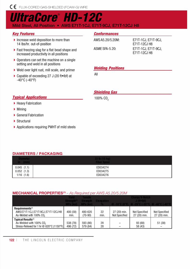
7/18/2019 c110 - Lincoln Electric Consumables 2014
http://slidepdf.com/reader/full/c110-lincoln-electric-consumables-2014 122/511122 ı T H E L I N C O L N E L E C T R I C C O M P A N Y
UltraCore ®
HD-12C FLUX-CORED GAS-SHIELDED (FCAW-G) WIRE
Welding Positions
Typical Applications
All
Heavy Fabrication
Mining
General Fabrication
Structural
Applications requiring PWHT of mild steels
Increase weld deposition to more than14 lbs/hr. out-of-position
Fast freezing slag for a flat bead shape andincreased productivity in all positions
Operators can set the machine on a singlesetting and weld in all positions
Weld over light rust, mill scale, and primer
Capable of exceeding 27 J (20 ft•lbf) at-40°C (-40°F)
Conformances
Shielding Gas 100% CO
2
Mild Steel, All Position • AWS E71T-1CJ, E71T-9CJ, E71T-12CJ H8
Key Features
AWS A5.20/5.20M:
ASME SFA-5.20:
E71T-1CJ, E71T-9CJ,E71T-12CJ H8
E71T-1CJ, E71T-9CJ,E71T-12CJ H8
DIAMETERS / PACKAGING
Diameter 33 lb (15 kg) Fiber Spoolin (mm)
0.0450.0521/16
(1.1)(1.3)(1.6)
ED034274ED034275ED034276
MECHANICAL PROPERTIES(1) – As Required per AWS A5.20/5.20M Yield
Strength(2)
TensileStrength Elongation
Charpy V-NotchJ (ft•lbf)
MPa (ksi) MPa (ksi) % @ -18°C (0°F) @ -29°C (-20°F) @ -40°C (-40°F)
Requirements(4)
AWS E71T-1CJ, E71T-9CJ, E71T-12CJ H8 As-Welded with 100% CO2
400 (58)
min.480-620(70-90)
22
min.27 (20) min.Not Specified
Not Specified27 (20) min.
Not Specified27 (20) min.
Typical Results(3)
As-Welded with 100% CO2
Stress-Relieved for 1 hr @ 620°C (1150°F)538 (78)496 (72)
593 (86)579 (84)
2828
––
93 (68)58 (43)
51 (38)–
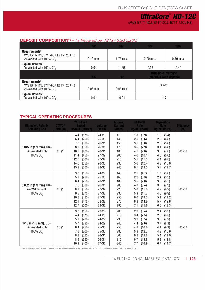
7/18/2019 c110 - Lincoln Electric Consumables 2014
http://slidepdf.com/reader/full/c110-lincoln-electric-consumables-2014 123/511W E L D I N G C O N S U M A B L E S C A TA L O G ı 123
UltraCore ®
HD-12C
FLUX-CORED GAS-SHIELDED (FCAW-G) WIRE
(AWS E71T-1CJ, E71T-9CJ, E71T-12CJ H8)
(1)Typical all weld metal. (2)Measured with 0.2% offset. (3)See test results disclaimer on pg. 18. (4) As-Welded with 100% CO2. (5)To estimate ESO, subtract 1/4 in (6.0 mm) from CTWD.
DEPOSIT COMPOSITION(1) – As Required per AWS A5.20/5.20M
%C %Mn %Si %Ni
Requirements(4)
AWS E71T-1CJ, E71T-9CJ, E71T-12CJ H8 As-Welded with 100% CO2
0.12 max.
1.75 max.
0.90 max.
0.50 max.
Typical Results(3)
As-Welded with 100% CO2 0.04 1.35 0.33 0.40
%S %PDiffusible Hydrogen
(mL/100g weld deposit)
Requirements(4)
AWS E71T-1CJ, E71T-9CJ, E71T-12CJ H8 As-Welded with 100% CO2
0.03 max.
0.03 max.
8 max.
Typical Results(3)
As-Welded with 100% CO2 0.01 0.01 4-7
TYPICAL OPERATING PROCEDURES
Diameter, Polarity
Shielding Gas
CTWD(5)
mm (in)
Wire FeedSpeed Voltage
(volts)
Approx.Current(amps)
Melt-OffRate
DepositionRate
Efficiency
(%)m/min (in/min) kg/hr (lb/hr) kg/hr (lb/hr)
0.045 in (1.1 mm), DC+ As-Welded with100% CO
2
25 (1)
4.46.47.6
8.910.211.412.714.015.2
(175)(250)(300)
(350)(400)(450)(500)(550)(600)
24-2925-3026-31
26-3126-3127-3227-3228-3328-33
115140155
170185200215230245
1.82.53.1
3.64.14.65.15.66.1
(3.9)(5.6)(6.8)
(7.9)(9.0)(10.1)(11.3)(12.4)(13.5)
1.52.22.6
3.13.54.04.44.95.3
(3.4)(4.8)(5.8)
(6.8)(7.8)(8.8)(9.8)(10.8)(11.7)
85-88
0.052 in (1.3 mm), DC+ As-Welded with
100% CO2
25 (1)
3.85.16.47.68.99.5
10.812.112.7
(150)(200)(250)(300)(350)(375)
(425)(475)(500)
24-2925-3026-3126-3127-3227-32
27-3228-3328-33
140160180205225235
255275290
2.12.93.54.35.05.3
6.06.87.1
(4.7)(6.3)(7.8)(9.4)(11.0)(11.7)
(13.3)(14.9)(15.6)
1.72.43.03.64.24.5
5.15.76.0
(3.8)(5.2)(6.5)(7.9)(9.2)(9.9)
(11.2)(12.6)(13.3)
85-88
1/16 in (1.6 mm), DC+ As-Welded with
100% CO2
25 (1)
3.84.45.15.76.47.68.38.9
10.2
(150)(175)(200)(225)(250)(300)(325)(350)(400)
23-2824-2924-2924-2925-3025-3026-3126-3127-32
200215230245255285300310340
2.93.43.94.44.85.86.36.77.7
(6.4)(7.5)(8.5)(9.6)(10.6)(12.7)(13.8)(14.8)(16.9)
2.42.93.33.74.14.95.45.86.7
(5.3)(6.3)(7.2)(8.1)(9.1)(10.9)(11.9)(12.8)(14.7)
85-88

7/18/2019 c110 - Lincoln Electric Consumables 2014
http://slidepdf.com/reader/full/c110-lincoln-electric-consumables-2014 124/511124 ı T H E L I N C O L N E L E C T R I C C O M P A N Y
UltraCore ®
712A80 FLUX-CORED GAS-SHIELDED (FCAW-G) WIRE
Welding Positions
Typical Applications
All
Offshore
Pressure vessels
Shipbuilding
Heavy equipment
ASME related applications
Capable of producing weld deposits withimpact toughness exceeding 27 J (20 ft•lbf)at -40°C (-40°F)
Designed for welding with 75-80% Argon/balance CO
2 shielding gas
Premium arc performance and beadappearance
Conformances
Shielding Gas
75% - 80% Argon / Balance CO2
Flow Rate: 40 - 50 CFH
Mild Steel, All Position • AWS E71T-1M-JH8, E71T-9M-JH8, E71T-12M-JH8
Key Features
AWS A5.20/A5.20M:
ASME SFA-A5.20:
ABS:
Lloyd’s Register:
DNV Grade:
CWB/CSA W48-06:
EN ISO 17632-B:
E71T-1M-JH8,E71T-9M-JH8,E71T-12M-JH8
E71T-1M-JH8,E71T-9M-JH8,E71T-12M-JH8
4YSA H10
4YS H10
IV YMS H10
E491T-12MJ-H8,E491T-9MJ-H8
T494T12-1MA-K-H10
DIAMETERS / PACKAGING
Diameter 15 lb (6.8 kg) Plastic Spool60 lb (27.2 kg) Master Carton
33 lb (15 kg)Spool*
50 lb (22.7 kg)Fiber Spool
500 lb (227 kg)Accu-Trak ® Drumin (mm)
0.0450.0521/16
(1.1)(1.3)(1.6) ED031890
ED031675ED031676ED031677
ED031850ED031851ED031852
ED032050ED032051ED032052
MECHANICAL PROPERTIES(1) – As Required per AWS A5.20/A5.20M Yield
Strength(2)
TensileStrength Elongation
Charpy V-NotchJ (ft•lbf)
MPa (ksi) MPa (ksi) % @ -18°C (0°F) @ -29°C (-20°F) @ -40°C (-40°F)
Requirements(4)
AWS E71T-1M-JH8
AWS E71T-9M-JH8
AWS E71T-12M-JH8
400 (58) min. 480-655 (70-95)
22 min.
27 (20) min. Not Specified
27 (20) min.Not Specified 27 (20) min.
480-620 (70-90) Not Specified 27 (20) min.
Typical Results(3)
As-Welded with75%-80% Ar/balance CO
2505-555 (73-80) 565-610 (82-88) 25-27 166-186 (123-137) 100-160 (74-118) 72-142 (53-105)
*Spool may be plastic or fiber.
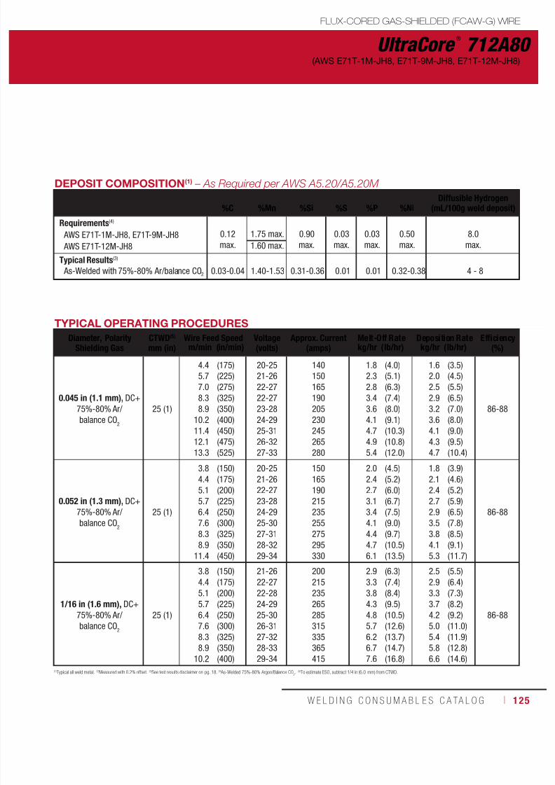
7/18/2019 c110 - Lincoln Electric Consumables 2014
http://slidepdf.com/reader/full/c110-lincoln-electric-consumables-2014 125/511W E L D I N G C O N S U M A B L E S C A TA L O G ı 125
UltraCore ®
712A80
FLUX-CORED GAS-SHIELDED (FCAW-G) WIRE
(AWS E71T-1M-JH8, E71T-9M-JH8, E71T-12M-JH8)
DEPOSIT COMPOSITION(1) – As Required per AWS A5.20/A5.20M
%C %Mn %Si %S %P %NiDiffusible Hydrogen
(mL/100g weld deposit)
Requirements(4)
AWS E71T-1M-JH8, E71T-9M-JH8
AWS E71T-12M-JH8
0.12max.
1.75 max. 0.90max.
0.03max.
0.03max.
0.50max.
8.0max.1.60 max.
Typical Results(3)
As-Welded with 75%-80% Ar/balance CO2 0.03-0.04 1.40-1.53 0.31-0.36 0.01 0.01 0.32-0.38 4 - 8
TYPICAL OPERATING PROCEDURES
Diameter, PolarityShielding Gas
CTWD(5)
mm (in)Wire Feed Speed Voltage
(volts)Approx. Current
(amps)Melt-Off Rate Deposition Rate Efficiency
(%)m/min (in/min) kg/hr (lb/hr) kg/hr (lb/hr)
0.045 in (1.1 mm), DC+75%-80% Ar/balance CO
2
25 (1)
4.45.77.08.38.9
10.211.412.113.3
(175)(225)(275)(325)(350)(400)(450)(475)(525)
20-2521-2622-2722-2723-2824-2925-3126-3227-33
140150165190205230245265280
1.82.32.83.43.64.14.74.95.4
(4.0)(5.1)(6.3)(7.4)(8.0)(9.1)(10.3)(10.8)(12.0)
1.62.02.52.93.23.64.14.34.7
(3.5)(4.5)(5.5)(6.5)(7.0)(8.0)(9.0)(9.5)(10.4)
86-88
0.052 in (1.3 mm), DC+75%-80% Ar/balance CO
2
25 (1)
3.84.45.15.76.47.6
8.38.911.4
(150)(175)(200)(225)(250)(300)
(325)(350)(450)
20-2521-2622-2723-2824-2925-30
27-3128-3229-34
150165190215235255
275295330
2.02.42.73.13.44.1
4.44.76.1
(4.5)(5.2)(6.0)(6.7)(7.5)(9.0)
(9.7)(10.5)(13.5)
1.82.12.42.72.93.5
3.84.15.3
(3.9)(4.6)(5.2)(5.9)(6.5)(7.8)
(8.5)(9.1)(11.7)
86-88
1/16 in (1.6 mm), DC+75%-80% Ar/balance CO
2
25 (1)
3.84.45.15.76.47.68.38.9
10.2
(150)(175)(200)(225)(250)(300)(325)(350)(400)
21-2622-2722-2824-2925-3026-3127-3228-3329-34
200215235265285315335365415
2.93.33.84.34.85.76.26.77.6
(6.3)(7.4)(8.4)(9.5)(10.5)(12.6)(13.7)(14.7)(16.8)
2.52.93.33.74.25.05.45.86.6
(5.5)(6.4)(7.3)(8.2)(9.2)(11.0)(11.9)(12.8)(14.6)
86-88
(1)Typical all weld metal. (2)Measured with 0.2% offset. (3)See test results disclaimer on pg. 18. (4) As-Welded 75%-80% Argon/Balance CO2. (5)To estimate ESO, subtract 1/4 in (6.0 mm) from CTWD.

7/18/2019 c110 - Lincoln Electric Consumables 2014
http://slidepdf.com/reader/full/c110-lincoln-electric-consumables-2014 126/511126 ı T H E L I N C O L N E L E C T R I C C O M P A N Y
UltraCore ®
HD-12M FLUX-CORED GAS-SHIELDED (FCAW-G) WIRE
Welding Positions
Typical Applications
All
Heavy Fabrication
Mining
General Fabrication
Increase weld deposition up to 14 lbs/hr.out-of-position
Results in a flat bead shape and enhancedproductivity in all positions
Operators can set the machine on a singlesetting and weld in all positions
Capable of exceeding 27 J (20 ft•lbf) at-40°C (-40°F)
Conformances
Shielding Gas
75-80% Argon / Balance CO2
Mild Steel, All Position • AWS E71T-1MJ, E71T-9MJ, E71T-12MJ H8
Key Features
AWS A5.20/5.20M:
ASME SFA-5.20:
E71T-1MJ, E71T-9MJ,E71T-12MJ H8
E71T-1MJ, E71T-9MJ,E71T-12MJ H8
DIAMETERS / PACKAGING
Diameter 33 lb (15 kg)Fiber Spoolin (mm)
0.0450.0521/16
(1.1)(1.3)(1.6)
ED034277ED034278ED034279
MECHANICAL PROPERTIES(1) – As Required per AWS A5.20/5.20M Yield
Strength(2)
TensileStrength Elongation
Charpy V-NotchJ (ft•lbf)
MPa (ksi) MPa (ksi) % @ -18°C (0°F) @ -29°C (-20°F) @ -40°C (-40°F)
Requirements AWS E71T-1MJ, E71T-9MJ, E71T-12MJ H8 As-Welded with 75-80% Ar / Balance CO2 400 (58) min. 480-655 (70-95) 22 min.
27 (20) min.Not Specified
Not Specified27 (20) min.
Not Specified27 (20) min.
Typical Results(3)
As-Welded with 75% Argon / 25% CO2Stress Relieved for 1 hr @ 620˚C (1150˚F)
538 (78)503 (73)
600 (87)593 (86)
2629
––
102 (75)68 (50)
65 (48)
–
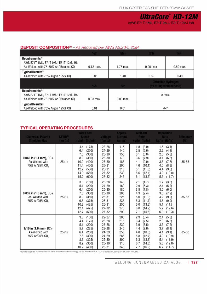
7/18/2019 c110 - Lincoln Electric Consumables 2014
http://slidepdf.com/reader/full/c110-lincoln-electric-consumables-2014 127/511W E L D I N G C O N S U M A B L E S C A TA L O G ı 127
UltraCore ®
HD-12M
FLUX-CORED GAS-SHIELDED (FCAW-G) WIRE
(AWS E71T-1MJ, E71T-9MJ, E71T-12MJ H8)
(1)Typical all weld metal. (2)Measured with 0.2% offset. (3)See test results disclaimer on pg. 18. (4) As-Welded with 100% CO2. (5)To estimate ESO, subtract 1/4 in (6.0 mm) from CTWD.
DEPOSIT COMPOSITION(1) – As Required per AWS A5.20/5.20M
%C %Mn %Si %Ni
Requirements(4)
AWS E71T-1MJ, E71T-9MJ, E71T-12MJ H8 As-Welded with 75-80% Ar / Balance CO2
0.12 max.
1.75 max.
0.90 max.
0.50 max.
Typical Results(3)
As-Welded with 75% Argon / 25% CO2
0.05
1.40
0.39
0.40
%S %P
Diffusible Hydrogen
(mL/100g weld deposit)
Requirements(4)
AWS E71T-1MJ, E71T-9MJ, E71T-12MJ H8
As-Welded with 75-80% Ar / Balance CO2
0.03 max.
0.03 max.
8 max.
Typical Results(3)
As-Welded with 75% Argon / 25% CO2
0.01
0.01
4-7
TYPICAL OPERATING PROCEDURES
Diameter, Polarity
Shielding Gas
CTWD(5)
mm (in)
Wire FeedSpeed Voltage
(volts)
Approx.Current(amps)
Melt-OffRate
DepositionRate
Efficiency
(%)m/min (in/min) kg/hr (lb/hr) kg/hr (lb/hr)
0.045 in (1.1 mm), DC+ As-Welded with75% Ar/25% CO
2
25 (1)
4.4
6.47.68.9
10.211.412.714.015.2
(175)
(250)(300)(350)(400)(450)(500)(550)(600)
23-28
24-2925-3025-3025-3026-3126-3127-3227-32
115
140155170185200215230245
1.8
2.53.13.64.14.65.15.66.1
(3.9)
(5.6)(6.8)(7.9)(9.0)(10.1)(11.3)(12.4)(13.5)
1.5
2.22.63.13.54.04.44.95.3
(3.4)
(4.8)(5.8)(6.8)(7.8)(8.8)(9.8)(10.8)(11.7)
85-88
0.052 in (1.3 mm), DC+ As-Welded with
75% Ar/25% CO2
25 (1)
3.85.16.47.68.9
9.510.812.112.7
(150)(200)(250)(300)(350)
(375)(425)(475)(500)
23-2824-2925-3025-3026-31
26-3126-3127-3227-32
140160180205225
235255275290
2.12.93.54.35.0
5.36.06.87.1
(4.7)(6.3)(7.8)(9.4)(11.0)
(11.7)(13.3)(14.9)(15.6)
1.72.43.03.64.2
4.55.15.76.0
(3.8)(5.2)(6.5)(7.9)(9.2)
(9.9)(11.)(12.6)(13.3)
85-88
1/16 in (1.6 mm), DC+ As-Welded with75% Ar/25% CO
2
25 (1)
3.84.45.15.76.47.68.38.9
10.2
(150)(175)(200)(225)(250)(300)(325)(350)(400)
22-2723-2823-2823-2824-2924-2925-3025-3026-31
200215230245255285300310340
2.93.43.94.44.85.86.36.77.7
(6.4)(7.5)(8.5)(9.6)(10.6)(12.7)(13.8)(14.8)(16.9)
2.42.93.33.74.14.95.45.86.7
(5.3)(6.3)(7.2)(8.1)(9.1)(10.9)(11.9)(12.8)(14.7)
85-88
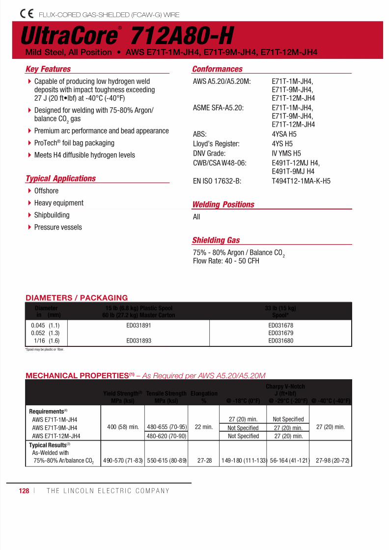
7/18/2019 c110 - Lincoln Electric Consumables 2014
http://slidepdf.com/reader/full/c110-lincoln-electric-consumables-2014 128/511128 ı T H E L I N C O L N E L E C T R I C C O M P A N Y
UltraCore ®
712A80-H FLUX-CORED GAS-SHIELDED (FCAW-G) WIRE
Welding Positions
Typical Applications
All
Offshore
Heavy equipment
Shipbuilding
Pressure vessels
Capable of producing low hydrogen welddeposits with impact toughness exceeding27 J (20 ft•lbf) at -40°C (-40°F)
Designed for welding with 75-80% Argon/balance CO
2 gas
Premium arc performance and bead appearance
ProTech® foil bag packaging
Meets H4 diffusible hydrogen levels
Conformances
Shielding Gas
75% - 80% Argon / Balance CO2
Flow Rate: 40 - 50 CFH
Mild Steel, All Position • AWS E71T-1M-JH4, E71T-9M-JH4, E71T-12M-JH4
Key Features
AWS A5.20/A5.20M:
ASME SFA-A5.20:
ABS:
Lloyd’s Register:
DNV Grade:
CWB/CSA W48-06:
EN ISO 17632-B:
E71T-1M-JH4,E71T-9M-JH4,E71T-12M-JH4
E71T-1M-JH4,E71T-9M-JH4,E71T-12M-JH4
4YSA H5
4YS H5
IV YMS H5
E491T-12MJ H4,E491T-9MJ H4
T494T12-1MA-K-H5
DIAMETERS / PACKAGING
Diameter 15 lb (6.8 kg) Plastic Spool60 lb (27.2 kg) Master Carton
33 lb (15 kg)Spool*in (mm)
0.0450.0521/16
(1.1)(1.3)(1.6)
ED031891
ED031893
ED031678ED031679ED031680
MECHANICAL PROPERTIES(1) – As Required per AWS A5.20/A5.20M
Yield Strength(2) Tensile Strength ElongationCharpy V-Notch
J (ft•lbf)
MPa (ksi) MPa (ksi) % @ -18°C (0°F) @ -29°C (-20°F) @ -40°C (-40°F)
Requirements(4)
AWS E71T-1M-JH4
AWS E71T-9M-JH4
AWS E71T-12M-JH4
400 (58) min. 480-655 (70-95)
22 min.
27 (20) min. Not Specified
27 (20) min.Not Specified 27 (20) min.
480-620 (70-90) Not Specified 27 (20) min.
Typical Results(3)
As-Welded with75%-80% Ar/balance CO2 490-570 (71-83) 550-615 (80-89) 27-28 149-180 (111-133) 56-164 (41-121) 27-98 (20-72)
*Spool may be plastic or fiber.
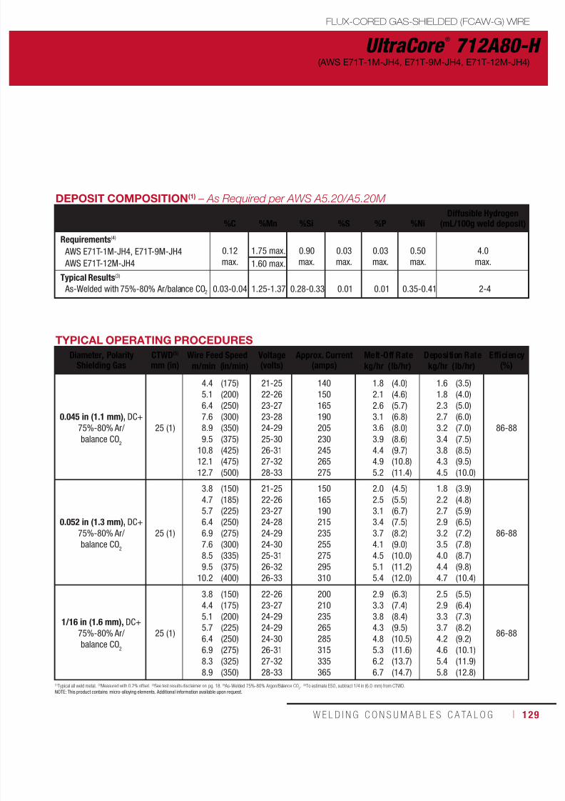
7/18/2019 c110 - Lincoln Electric Consumables 2014
http://slidepdf.com/reader/full/c110-lincoln-electric-consumables-2014 129/511W E L D I N G C O N S U M A B L E S C A TA L O G ı 129
UltraCore ®
712A80-H
FLUX-CORED GAS-SHIELDED (FCAW-G) WIRE
(AWS E71T-1M-JH4, E71T-9M-JH4, E71T-12M-JH4)
DEPOSIT COMPOSITION(1) – As Required per AWS A5.20/A5.20M
%C %Mn %Si %S %P %NiDiffusible Hydrogen
(mL/100g weld deposit)
Requirements(4)
AWS E71T-1M-JH4, E71T-9M-JH4
AWS E71T-12M-JH4
0.12max.
1.75 max. 0.90max.
0.03max.
0.03max.
0.50max.
4.0max.1.60 max.
Typical Results(3)
As-Welded with 75%-80% Ar/balance CO2 0.03-0.04 1.25-1.37 0.28-0.33 0.01 0.01 0.35-0.41 2-4
TYPICAL OPERATING PROCEDURES
Diameter, PolarityShielding Gas
CTWD(5)
mm (in)Wire Feed Speed Voltage
(volts)Approx. Current
(amps)Melt-Off Rate Deposition Rate Efficiency
(%)m/min (in/min) kg/hr (lb/hr) kg/hr (lb/hr)
0.045 in (1.1 mm), DC+75%-80% Ar/balance CO
2
25 (1)
4.45.16.47.68.99.5
10.812.112.7
(175)(200)(250)(300)(350)(375)(425)(475)(500)
21-2522-2623-2723-2824-2925-3026-3127-3228-33
140150165190205230245265275
1.82.12.63.13.63.94.44.95.2
(4.0)(4.6)(5.7)(6.8)(8.0)(8.6)(9.7)(10.8)(11.4)
1.61.82.32.73.23.43.84.34.5
(3.5)(4.0)(5.0)(6.0)(7.0)(7.5)(8.5)(9.5)(10.0)
86-88
0.052 in (1.3 mm), DC+75%-80% Ar/
balance CO2
25 (1)
3.84.75.76.46.9
7.68.59.5
10.2
(150)(185)(225)(250)(275)
(300)(335)(375)(400)
21-2522-2623-2724-2824-29
24-3025-3126-3226-33
150165190215235
255275295310
2.02.53.13.43.7
4.14.55.15.4
(4.5)(5.5)(6.7)(7.5)(8.2)
(9.0)(10.0)(11.2)(12.0)
1.82.22.72.93.2
3.54.04.44.7
(3.9)(4.8)(5.9)(6.5)(7.2)
(7.8)(8.7)(9.8)(10.4)
86-88
1/16 in (1.6 mm), DC+75%-80% Ar/balance CO
2
25 (1)
3.84.45.15.76.46.98.38.9
(150)(175)(200)(225)(250)(275)(325)(350)
22-2623-2724-2924-2924-3026-3127-3228-33
200210235265285315335365
2.93.33.84.34.85.36.26.7
(6.3)(7.4)(8.4)(9.5)(10.5)(11.6)(13.7)(14.7)
2.52.93.33.74.24.65.45.8
(5.5)(6.4)(7.3)(8.2)(9.2)(10.1)(11.9)(12.8)
86-88
(1)Typical all weld metal. (2)Measured with 0.2% offset. (3)See test results disclaimer on pg. 18. (4) As-Welded 75%-80% Argon/Balance CO2. (5)To estimate ESO, subtract 1/4 in (6.0 mm) from CTWD.NOTE: This product contains micro-alloying elements. Additional information available upon request.
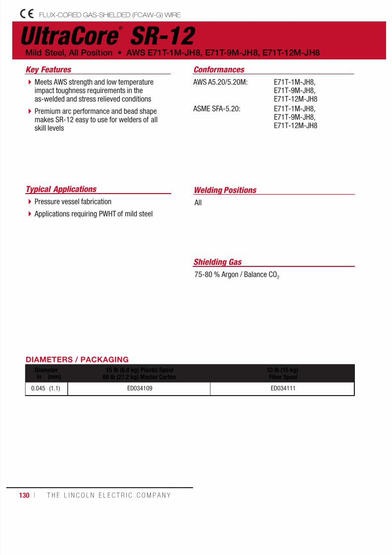
7/18/2019 c110 - Lincoln Electric Consumables 2014
http://slidepdf.com/reader/full/c110-lincoln-electric-consumables-2014 130/511130 ı T H E L I N C O L N E L E C T R I C C O M P A N Y
UltraCore ®
SR-12 FLUX-CORED GAS-SHIELDED (FCAW-G) WIRE
Welding Positions Typical Applications AllPressure vessel fabrication
Applications requiring PWHT of mild steel
Meets AWS strength and low temperatureimpact toughness requirements in theas-welded and stress relieved conditions
Premium arc performance and bead shapemakes SR-12 easy to use for welders of allskill levels
Conformances
Shielding Gas
75-80 % Argon / Balance CO2
Mild Steel, All Position • AWS E71T-1M-JH8, E71T-9M-JH8, E71T-12M-JH8
Key Features
AWS A5.20/5.20M:
ASME SFA-5.20:
E71T-1M-JH8,E71T-9M-JH8,E71T-12M-JH8
E71T-1M-JH8,E71T-9M-JH8,E71T-12M-JH8
DIAMETERS / PACKAGING
Diameter 15 lb (6.8 kg) Plastic Spool
60 lb (27.2 kg) Master Carton
33 lb (15 kg)
Fiber Spoolin (mm)0.045 (1.1) ED034109 ED034111
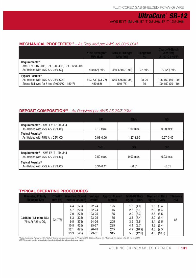
7/18/2019 c110 - Lincoln Electric Consumables 2014
http://slidepdf.com/reader/full/c110-lincoln-electric-consumables-2014 131/511W E L D I N G C O N S U M A B L E S C A TA L O G ı 131
MECHANICAL PROPERTIES(1) – As Required per AWS A5.20/5.20M
Yield Strength(2) Tensile Strength ElongationCharpy V-Notch
J (ft•lbf)
MPa (ksi) MPa (ksi) % @ -40°C (-40°F)
Requirements(4)
AWS E71T-1M-JH8, E71T-9M-JH8, E71T-12M-JH8 As-Welded with 75% Ar / 25% CO2
400 (58) min.
480-620 (70-90)
22 min.
27 (20) min.
Typical Results(3)
As-Welded with 75% Ar / 25% CO2Stress-Relieved for 8 hrs. @ 620°C (1150°F)
503-530 (73-77)450 (65)
565-586 (82-85)540 (78)
28-2930
108-162 (80-120)100-150 (70-110)
UltraCore ®
SR-12
FLUX-CORED GAS-SHIELDED (FCAW-G) WIRE
(AWS E71T-1M-JH8, E71T-9M-JH8, E71T-12M-JH8)
DEPOSIT COMPOSITION(1) – As Required per AWS A5.20/5.20M
%C %Mn %Si
Requirements(4) - AWS E71T-12M-JH4
As-Welded with 75% Ar / 25% CO20.12 max. 1.60 max. 0.90 max.
Typical Results(3)
As-Welded with 75% Ar / 25% CO2 0.03-0.06 1.27-1.60 0.27-0.45
%Ni %S
%P
Requirements(4) - AWS E71T-12M-JH4
As-Welded with 75% Ar / 25% CO20.50 max. 0.03 max. 0.03 max.
Typical Results(3)
As-Welded with 75% Ar / 25% CO2 0.34-0.41 <0.01 <0.01
TYPICAL OPERATING PROCEDURESDiameter, Polarity
Shielding GasCTWD(5)
mm (in)Wire Feed Speed Voltage
(volts)Approx. Current
(amps)Melt-Off Rate Deposition Rate Efficiency
(%)m/min (in/min) kg/hr (lb/hr) kg/hr (lb/hr)
0.045 in (1.1 mm), DC+75% Ar / 25% CO
2
22 (7/8)
4.45.77.08.39.5
10.812.113.3
(175)(225)(275)(325)(375)(425)(475)(525)
22-2422-2423-2523-2524-2625-2726-2829-31
125145165185205225245315
1.82.32.93.43.94.44.95.5
(4.0)(5.1)(6.3)(7.4)(8.6)(9.7)(10.9)(12.0)
1.52.02.52.93.43.84.34.8
(3.4)(4.4)(5.5)(6.4)(7.5)(8.4)(9.5)(10.6)
88
(1)Typical all weld metal. (2)Measured with 0.2% offset. (3)See test results disclaimer on pg. 18. (4) As-Welded 75%-80% Argon/Balance CO2. (5)To estimate ESO, subtract 1/4 in (6.0 mm) from CTWD.NOTE: This product contains micro-alloying elements. Additional information available upon request.

7/18/2019 c110 - Lincoln Electric Consumables 2014
http://slidepdf.com/reader/full/c110-lincoln-electric-consumables-2014 132/511132 ı T H E L I N C O L N E L E C T R I C C O M P A N Y
UltraCore ®
SR-12C FLUX-CORED GAS-SHIELDED (FCAW-G) WIRE
Mild Steel, All Position • AWS E71T-12C-JH8
100% CO2
ApplicationsKey Features
Welding Positions
Conformances
Shielding Gas
Capable of meeting 20 ft•lbf @ -50°F in boththe as-welded and stress relieved conditions
A premium arc performance and fast freezingslag make UltraCore® SR-12C easy to use forwelders of all skill levels
General Fabrication
Offshore Industry Petrochemical
AWS A5.20/5.20M:
AWS A5.36:
ASME SFA-5.20:
E71T-12C-JH8
E71T12-C1A5-CS2-H8,E71T12-C1P5-CS2-H8
E71T-12C-JH8
All
DIAMETERS / PACKAGING
Diameter 33 lb (15 kg)
Fiber Spoolin. (mm)
0.0450.0521/16
(1.1)(1.3)(1.6)
ED034532ED034533ED034534

7/18/2019 c110 - Lincoln Electric Consumables 2014
http://slidepdf.com/reader/full/c110-lincoln-electric-consumables-2014 133/511W E L D I N G C O N S U M A B L E S C A TA L O G ı 133
UltraCore ®
SR-12C
FLUX-CORED GAS-SHIELDED (FCAW-G) WIRE
(AWS E71T-12C-JH8)
MECHANICAL PROPERTIES(1) – As Required per AWS A5.36/5.36M
Yield Strength(2)
Tensile Strength Elongation
Charpy V-NotchJ (ft•lbf)
MPa (ksi) MPa (ksi) % @ -40°C (-40°F) @ -46°C (-50°F)
Requirements AWS A5.20 - E71T-12C-JH8
As-Welded with 100% CO2
400 (58) min.
480-620 (70-90)
22 min.
27 (20) min. –
AWS A5.36 - E71T1-C1A5-CS2-H8 As-Welded with 100% CO2 480-655 (70-95) – 27 (20) min.
AWS A5.36 - E71T1-C1P5-CS2-H8Stress Relieved 1hr. @ 620°C (1150°F) with100% CO2
480-655 (70-95) – 27 (20) min.
Test Results(3)
As-Welded with 100% CO2
Stress-Relieved 1 hr. @ 620°C (1150°F) with100% CO2
490 (71)435 (63)
550 (80)545 (79)
2232
47 (34)-
61 (45)92 (68)
DEPOSIT COMPOSITION(1) – As Required per AWS A5.36/5.36M
%C %Mn %Si %S %P %Ni
Diffusible Hydrogen(mL/100g weld
deposit)
Requirements AWS A5.20 - E71T-12C-JH8 As-Welded with 100% CO2
AWS A5.36 - E71T1-C1A5-CS2-H8 As-Welded with100% CO2
0.12max.
1.75 max.1.60 max.
0.90max.
0.03 max.0.030 max.
0.03 max.0.030 max.
0.50max. 3.0 max.
Test Results(3) As-Welded with 100% CO
20.05 1.42 0.52 0.007 0.016 0.02 5.9
TYPICAL OPERATING PROCEDURESDiameter, Polarity
Shielding GasCTWD(4)
mm (in)Wire Feed Speedm/min (in/min)
Voltage(Volts)
Approx. Current(Amps)
Melt-Off Ratekg/hr (lb/hr)
Deposition Ratekg/hr (lb/hr)
Efficiency(%)
0.045 in. (1.1 mm), DC+ As-Welded with
100% CO2
25 (1)
4.46.47.6
10.2
12.75.2
(175)(250)(300)(400)
(500)(600)
23-2824-2925-3025-30
26-3127-32
115140155185
215245
1.82.53.14.1
5.16.1
(3.9)(5.6)(6.8)(9.0)
(11.3)(13.5)
1.52.12.63.4
4.45.1
(3.4)(4.6)(5.8)(7.5)
(9.8)(11.3)
85-88
0.052 in. (1.3 mm), DC+ As-Welded with
100% CO2
25 (1)
3.86.48.9
10.812.7
(150)(250)(350)(425)(500)
23-2825-3026-3126-3127-32
140180225255290
2.13.55.06.07.1
(4.7)(7.8)(11.0)(13.3)(15.6)
1.73.04.25.16.0
(3.8)(6.5)(9.2)(11.2)(13.3)
85-88
1/16 in. (1.6 mm), DC+ As-Welded with
100% CO2
25 (1)
3.85.16.47.6
10.2
(150)(200)(250)(300)(400)
22-2723-2824-2925-3026-31
200230255300360
2.93.74.85.56.7
(6.4)(8.1)(10.6)(12.1)(14.8)
2.43.04.14.65.8
(5.3)(6.7)(9.1)(10.2)(12.8)
85-88
(1) Typical all weld metal. (2) Measured with 0.2% offset. (3) See test results disclaimer on pg. 18. (4) To estimate ESO, subtract 1/4 in. (6.0 mm) from CTWD.

7/18/2019 c110 - Lincoln Electric Consumables 2014
http://slidepdf.com/reader/full/c110-lincoln-electric-consumables-2014 134/511134 ı T H E L I N C O L N E L E C T R I C C O M P A N Y
UltraCore ®
SR-12M FLUX-CORED GAS-SHIELDED (FCAW-G) WIRE
Mild Steel, All Position • AWS E71T-12MJ
75 - 80% Argon / balance CO2
Typical ApplicationsKey Features
Welding Positions
Conformances
Shielding Gas
Capable of meeting 20 ft•lbf @ -50°F in boththe as-welded and stress relieved conditions
A premium arc performance makeUltraCore® SR-12M easy to use for weldersof all skill levels
General Fabrication
Offshore Industry Petrochemical
AWS A5.36/5.36M:
AWS A5.36/5.36M:
ASME SFA-5.36:
E71T-12M J
E71T12-M21A5-CS2-H8,E71T12-M21P5-CS2-H8
E71T-12M J
All
DIAMETERS / PACKAGING
Diameter 33 lb (15 kg)
Fiber Spoolin. (mm)
0.0450.0521/16
(1.1)(1.3)(1.6)
ED034529ED034530ED034531
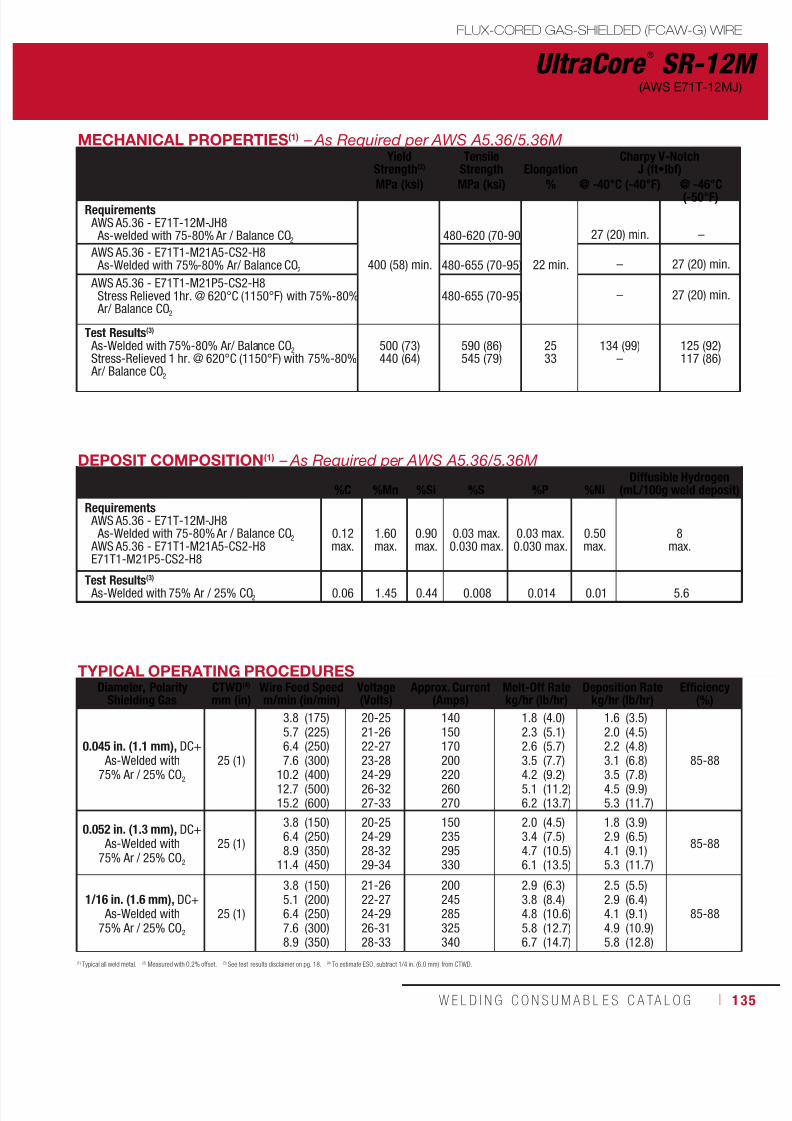
7/18/2019 c110 - Lincoln Electric Consumables 2014
http://slidepdf.com/reader/full/c110-lincoln-electric-consumables-2014 135/511W E L D I N G C O N S U M A B L E S C A TA L O G ı 135
UltraCore ®
SR-12M
FLUX-CORED GAS-SHIELDED (FCAW-G) WIRE
(AWS E71T-12MJ)
MECHANICAL PROPERTIES(1) – As Required per AWS A5.36/5.36MYield
Strength(2)
TensileStrength Elongation
Charpy V-NotchJ (ft•lbf)
MPa (ksi) MPa (ksi) % @ -40°C (-40°F) @ -46°C(-50°F)
Requirements AWS A5.36 - E71T-12M-JH8
As-welded with 75-80% Ar / Balance CO2
400 (58) min.
480-620 (70-90
22 min.
27 (20) min. –
AWS A5.36 - E71T1-M21A5-CS2-H8 As-Welded with 75%-80% Ar/ Balance CO2 480-655 (70-95)
– 27 (20) min.
AWS A5.36 - E71T1-M21P5-CS2-H8Stress Relieved 1hr. @ 620°C (1150°F) with 75%-80% Ar/ Balance CO2
480-655 (70-95) – 27 (20) min.
Test Results(3)
As-Welded with 75%-80% Ar/ Balance CO2
Stress-Relieved 1 hr. @ 620°C (1150°F) with 75%-80% Ar/ Balance CO2
500 (73)440 (64)
590 (86)545 (79)
2533
134 (99)–
125 (92)117 (86)
DEPOSIT COMPOSITION(1) – As Required per AWS A5.36/5.36M
%C %Mn %Si %S %P %NiDiffusible Hydrogen
(mL/100g weld deposit)
Requirements AWS A5.36 - E71T-12M-JH8
As-Welded with 75-80% Ar / Balance CO2 AWS A5.36 - E71T1-M21A5-CS2-H8E71T1-M21P5-CS2-H8
0.12max.
1.60max.
0.90max.
0.03 max.0.030 max.
0.03 max.0.030 max.
0.50max.
8max.
Test Results(3) As-Welded with 75% Ar / 25% CO2 0.06 1.45 0.44 0.008 0.014 0.01 5.6
TYPICAL OPERATING PROCEDURESDiameter, Polarity
Shielding GasCTWD(4)
mm (in)Wire Feed Speedm/min (in/min)
Voltage(Volts)
Approx. Current(Amps)
Melt-Off Ratekg/hr (lb/hr)
Deposition Ratekg/hr (lb/hr)
Efficiency(%)
0.045 in. (1.1 mm), DC+
As-Welded with75% Ar / 25% CO225 (1)
3.85.76.4
7.610.212.715.2
(175)(225)(250)
(300)(400)(500)(600)
20-2521-2622-27
23-2824-2926-3227-33
140150170
200220260270
1.82.32.6
3.54.25.16.2
(4.0)(5.1)(5.7)
(7.7)(9.2)(11.2)(13.7)
1.62.02.2
3.13.54.55.3
(3.5)(4.5)(4.8)
(6.8)(7.8)(9.9)(11.7)
85-88
0.052 in. (1.3 mm), DC+ As-Welded with
75% Ar / 25% CO2
25 (1)
3.86.48.9
11.4
(150)(250)(350)(450)
20-2524-2928-3229-34
150235295330
2.03.44.76.1
(4.5)(7.5)(10.5)(13.5)
1.82.94.15.3
(3.9)(6.5)(9.1)(11.7)
85-88
1/16 in. (1.6 mm), DC+ As-Welded with
75% Ar / 25% CO2
25 (1)
3.85.16.47.68.9
(150)(200)(250)(300)(350)
21-2622-2724-2926-3128-33
200245285325340
2.93.84.85.86.7
(6.3)(8.4)(10.6)(12.7)(14.7)
2.52.94.14.95.8
(5.5)(6.4)(9.1)(10.9)(12.8)
85-88
(1) Typical all weld metal. (2) Measured with 0.2% offset. (3) See test results disclaimer on pg. 18. (4) To estimate ESO, subtract 1/4 in. (6.0 mm) from CTWD.

7/18/2019 c110 - Lincoln Electric Consumables 2014
http://slidepdf.com/reader/full/c110-lincoln-electric-consumables-2014 136/511136 ı T H E L I N C O L N E L E C T R I C C O M P A N Y
Outershield ®
71 Elite
Welding Positions
Typical Applications
All
Shipbuilding, barges and offshore platforms
Heavy equipment
Structural fabrication
General fabrication
Smooth arc transfer and low spatter
Designed for welding with either 100% CO2 or 75-82% Argon/balance CO
2 shielding gases
Good bead appearance
Fast freezing slag for out-of-position welding
Meets AWS D1.8 seismic lot waiver requirements
Conformances
Shielding Gas
100% CO2
75 - 82% Argon / Balance CO2Flow Rate: 40 - 50 CFH
Mild Steel, All Position • AWS E71T-1C-H8, E71T-9C-H8, E71T-1M-H8, E71T-9M-H8
Key Features
AWS A5.20/A5.20M:
ASME SFA-A5.20:
ABS:
DNV Grade:
GL:
LR:CWB/CSA W48-06:
E71T-1C-H8, E71T-9C-H8,E71T-1M-H8, E71T-9M-H8
E71T-1C-H8, E71T-9C-H8,E71T-1M-H8, E71T-9M-H8
3SA, 3YSA H10
III YMS H10
3YH10S
3YS H10
E491T-9-H8, E491T-9M-H8
DIAMETERS / PACKAGING
Diameter 15 lb (6.8 kg) Plastic Spool60 lb (27.2 kg) Master Carton
33 lb (15 kg)Steel Spool
60 lb (27.2 kg)Coil
600 lb (272 kg)Accu-Trak ® Drumin (mm)
0.0450.0521/16
(1.1)(1.3)(1.6)
ED029418ED029419
ED029201ED029204ED029206
ED029202ED029205ED029207 ED029387
FLUX-CORED GAS-SHIELDED (FCAW-G) WIREuctural Welding Code
smic Supplement

7/18/2019 c110 - Lincoln Electric Consumables 2014
http://slidepdf.com/reader/full/c110-lincoln-electric-consumables-2014 137/511W E L D I N G C O N S U M A B L E S C A TA L O G ı 137
Outershield ®
71 Elite(AWS E71T-1C-H8, E71T-9C-H8, E71T-1M-H8, E71T-9M-H8)
DEPOSIT COMPOSITION(1) – As Required per AWS A5.20/A5.20M
%C %Mn %Si %S %P
Requirements
AWS E71T-1C-H8, E71T-9C-H8 AWS E71T-1M-H8, E71T-9M-H8
0.12max.
1.75max.
0.90max.
0.03max.
0.03max.
Typical Results(3)
As-Welded with 100% CO2
As-Welded with 75% Ar/25% CO2
0.01-0.040.02-0.04
1.41-1.501.55-1.65
0.44-0.600.56-0.75
≤0.01≤0.01
≤0.01≤0.01
(1)Typical all weld metal. (2)Measured with 0.2% offset. (3)See test results disclaimer on pg. 18. (4)When welding under CO2, increase voltage by 1 Volt. (5)To estimate ESO, subtract 1/4 in (6.0 mm) from CTWD.
TYPICAL OPERATING PROCEDURES
Diameter, PolarityShielding Gas(4)
CTWD(5)
mm (in)Wire Feed Speed Voltage
(volts)Approx. Current
(amps)Melt-Off Rate Deposition Rate Efficiency
(%)m/min (in/min) kg/hr (lb/hr) kg/hr (lb/hr)
0.045 in (1.1 mm), DC+75% Ar / 25% CO
219 (3/4)
4.56.47.68.9
10.212.815.3
(175)(250)(300)(350)(400)(500)(600)
21-2423-2624-2725-2826-2927-3028-31
130155180205230260290
1.72.42.93.44.05.06.0
(3.8)(5.4)(6.4)(7.6)(8.7)(10.9)(13.1)
1.52.12.53.03.54.35.2
(3.3)(4.7)(5.6)(6.6)(7.6)(9.5)(11.4)
87878787878787
0.052 in (1.3 mm), DC+75% Ar / 25% CO
219 (3/4)
3.85.16.47.6
10.212.8
(150)(200)(250)(300)(400)(500)
21-2422-2523-2624-2726-2828-31
150180210240315335
2.12.83.44.86.26.9
(4.6)(6.1)(7.6)(10.6)(13.7)(15.2)
1.82.43.04.15.46.0
(3.9)(5.2)(6.5)(9.1)(11.8)(13.1)
868686868686
1/16 (1.6 mm), DC+75% Ar / 25% CO
219 (3/4)
3.23.85.16.47.6
10.2
(125)(150)(200)(250)(300)(400)
21-2422-2522-2623-2724-2827-31
190205240290325400
2.42.83.84.75.67.5
(5.2)(6.2)(8.3)(10.3)(12.4)(16.5)
2.02.43.24.04.86.4
(4.4)(5.3)(7.0)(8.8)(10.5)(14.0)
858585858585
FLUX-CORED GAS-SHIELDED (FCAW-G) WIRE
MECHANICAL PROPERTIES(1) – As Required per AWS A5.20/A5.20M
Yield Strength(2) Tensile Strength ElongationCharpy V-Notch
J (ft•lbf)MPa (ksi) MPa (ksi) % @ -18°C (0°F) @ -29°C (-20°F)
Requirements
AWS E71T-1C-H8, E71T-9C-H8 AWS E71T-1M-H8, E71T-9M-H8
400 (58) min.
485-655 (70-95)
22 min.
27 (20) min.
–
– 27 (20) min.
Typical Results(3)
As-Welded with 100% CO2
As-Welded with 75% Ar/25% CO2
545-565 (79-82)585-595 (85-87)
585-615 (85-90)625-630 (91-92)
2825-28
74-83 (55-61)92-99 (68-73)
58-64 (43-47)70-83 (52-61)

7/18/2019 c110 - Lincoln Electric Consumables 2014
http://slidepdf.com/reader/full/c110-lincoln-electric-consumables-2014 138/511138 ı T H E L I N C O L N E L E C T R I C C O M P A N Y
*Made to Order (MTO)
Outershield ®
71 Supreme FLUX-CORED GAS-SHIELDED (FCAW-G) WIRE
Welding Positions
Typical Applications
All
Mining
Offshore
Bridge fabrication
High strength fabrication
Structural steel
Designed to be used with either 100% CO2
or 75% Argon/25% CO2 gas
Smooth, consistent arc performance
The finished weld exhibits an extremely smoothbead appearance, even on out-of-position welds
Meets H4 diffusible hydrogen levels
Conformances
Shielding Gas
75% Argon / 25% CO2
100% CO2
Flow Rate: 40 - 50 CFH
Mild Steel, All Position • AWS E71T-1C-H4, E71T-9C-H4, E71T-1M-H4, E71T-9M-H4
Key Features
AWS A5.20/A5.20M:
ASME SFA-A5.20:
CWB/CSA W48-06:
E71T-1C-H4, E71T-9C-H4E71T-1M-H4, E71T-9M-H4
E71T-1C-H4, E71T-9C-H4E71T-1M-H4, E71T-9M-H4
E491T-9-H4, E491T-9M-H4
Note
This product is only sold in Canada.
This product contains micro-alloying elements. Additional information available upon request.
DIAMETERS / PACKAGING
Diameter 33 lb (15 kg)Spool
500 lb (227 kg)Accu-Trak ® Drum
600 lb (272 kg)Accu-Trak ® Drumin (mm)
0.0450.0521/16
(1.1)(1.3)(1.6)
ED503040ED503041ED503042
ED503046*ED503047*
ED503048*
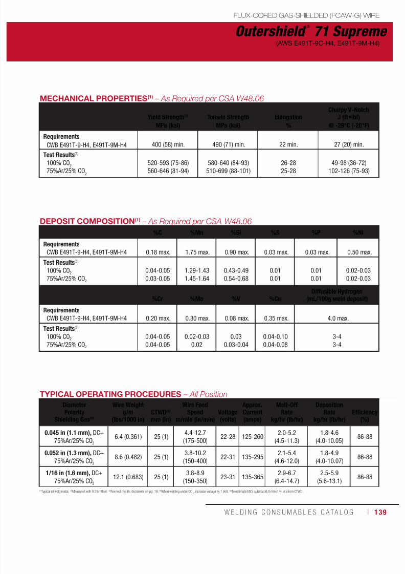
7/18/2019 c110 - Lincoln Electric Consumables 2014
http://slidepdf.com/reader/full/c110-lincoln-electric-consumables-2014 139/511W E L D I N G C O N S U M A B L E S C A TA L O G ı 139
Outershield ®
71 Supreme
FLUX-CORED GAS-SHIELDED (FCAW-G) WIRE
(AWS E491T-9C-H4, E491T-9M-H4)
TYPICAL OPERATING PROCEDURES – All PositionDiameterPolarity
Shielding Gas(4)
Wire Weightg/m
(lbs/1000 in)
CTWD(5)
mm (in)
Wire FeedSpeed Voltage
(volts)
Approx.Current(amps)
Melt-OffRate
DepositionRate
Efficiency
(%)m/min (in/min) kg/hr (lb/hr) kg/hr (lb/hr)
0.045 in (1.1 mm), DC+75%Ar/25% CO2
6.4 (0.361) 25 (1)4.4-12.7(175-500)
22-28 125-2602.0-5.2
(4.5-11.3)1.8-4.6
(4.0-10.05)86-88
0.052 in (1.3 mm), DC+75%Ar/25% CO2
8.6 (0.482) 25 (1)3.8-10.2(150-400)
22-31 135-2952.1-5.4
(4.6-12.0)1.8-4.9
(4.0-10.07)86-88
1/16 in (1.6 mm), DC+75%Ar/25% CO2
12.1 (0.683) 25 (1)3.8-8.9
(150-350)23-31 135-365
2.9-6.7(6.4-14.7)
2.5-5.9(5.6-13.1)
86-88
(1)Typical all weld metal. (2)Measured with 0.2% offset. (3)See test results disclaimer on pg. 18. (4)When welding under CO2, increase voltage by 1 Volt. (5)To estimate ESO, subtract 6.0 mm (1/4 in.) from CTWD.
MECHANICAL PROPERTIES(1) – As Required per CSA W48.06
Yield Strength(2) Tensile Strength ElongationCharpy V-Notch
J (ft•lbf)
MPa (ksi) MPa (ksi) % @ -29°C (-20°F)
Requirements
CWB E491T-9-H4, E491T-9M-H4
400 (58) min. 490 (71) min.
22 min.
27 (20) min.
Test Results(3)
100% CO2
75%Ar/25% CO2
520-593 (75-86)560-646 (81-94)
580-640 (84-93)510-699 (88-101)
26-2825-28
49-98 (36-72)102-126 (75-93)
DEPOSIT COMPOSITION(1) – As Required per CSA W48.06
%C %Mn %Si %S %P %Ni
Requirements
CWB E491T-9-H4, E491T-9M-H4 0.18 max. 1.75 max. 0.90 max. 0.03 max. 0.03 max. 0.50 max.
Test Results(3)
100% CO2 75%Ar/25% CO2
0.04-0.050.03-0.05
1.29-1.431.45-1.64
0.43-0.490.54-0.68
0.010.01
0.010.01
0.02-0.030.02-0.03
%Cr %Mo %V %Cu Diffusible Hydrogen(mL/100g weld deposit)
Requirements
CWB E491T-9-H4, E491T-9M-H4 0.20 max. 0.30 max. 0.08 max. 0.35 max. 4.0 max.
Test Results(3)
100% CO2 75%Ar/25% CO2
0.04-0.050.04-0.05
0.02-0.030.02
0.030.03-0.04
0.04-0.100.04-0.08
3-43-4
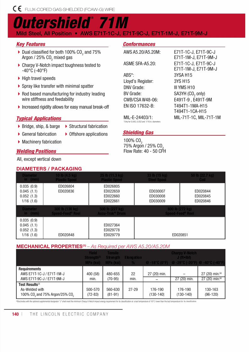
7/18/2019 c110 - Lincoln Electric Consumables 2014
http://slidepdf.com/reader/full/c110-lincoln-electric-consumables-2014 140/511140 ı T H E L I N C O L N E L E C T R I C C O M P A N Y
Outershield ®
71M FLUX-CORED GAS-SHIELDED (FCAW-G) WIRE
Welding Positions
Typical Applications
All, except vertical down
Bridge, ship, & barge
General fabrication
Machinery fabrication
Structural fabrication
Offshore applications
Dual classified for both 100% CO2 and 75%
Argon / 25% CO2 mixed gas
Charpy V-Notch impact toughness tested to-40°C (-40°F)
High travel speeds
Spray like transfer with minimal spatter
Rod based manufacturing for industry leadingwire stiffness and feedability
Increased rigidity allows for easy manual break-off
Conformances
Shielding Gas
100% CO2
75% Argon / 25% CO2
Flow Rate: 40 - 50 CFH
Mild Steel, All Position • AWS E71T-1C-J, E71T-9C-J, E71T-1M-J, E71T-9M-J
Key Features
AWS A5.20/A5.20M:
ASME SFA-A5.20:
ABS*:
Lloyd’s Register:
DNV Grade:
BV Grade:
CWB/CSA W48-06:
EN ISO 17632-B:
MIL-E-24403/1:
E71T-1C-J, E71T-9C-JE71T-1M-J, E71T-9M-J
E71T-1C-J, E71T-9C-JE71T-1M-J, E71T-9M-J
3YSA H15
3YS H15
III YMS H10
SA3YH (CO2 only)
E491T-9 , E491T-9M
T494T1-1MA-H15T494T1-1CA-H15
MIL-71T-1C, MIL-71T-1M
DIAMETERS / PACKAGING
Diameter 10 lb (4.5 kg)
Plastic Spool
25 lb (11.3 kg)
Plastic Spool
33 lb (15 kg)
Steel Spool
50 lb (22.7 kg)
Coilin (mm)0.0350.0450.0521/16
(0.9)(1.1)(1.3)(1.6)
ED026804ED020836
ED026805ED022659ED022660ED022661
ED030007ED030008ED030009
ED020844ED020845ED020846
Diameter 300 lb (136 kg)Speed-Feed® Reel
500 lb (227 kg)Accu-Trak ® Drum
600 lb (272 kg)Speed-Feed® Reelin (mm)
0.0350.0450.0521/16
(0.9)(1.1)(1.3)(1.6) ED020848
ED027364ED029778ED029779 ED020851
(a)Electrodes with the optional supplemental designator “J” shall meet the minimum Charpy V-Notch impact energy requirement for its classification at a test temperature of 10°C lower than the test temperature for its classification.
*Only for 0.045, 0.052 and 1/16 in. diameters
MECHANICAL PROPERTIES(1) – As Required per AWS A5.20/A5.20M
YieldStrength(2)
TensileStrength Elongation
Charpy V-NotchJ (ft•lbf)
MPa (ksi) MPa (ksi) % @ -18°C (0°F) @ -29°C (-20°F) @ -40°C (-40°F)
Requirements
AWS E71T-1C-J / E71T-1M-J AWS E71T-9C-J / E71T-9M-J
400 (58)
min.
480-655(70-95)
22
min.
27 (20) min.
–
27 (20) min.(a)
– 27 (20) min. 27 (20) min.(a)
Test Results(3)
As-Welded with100% CO
2and 75% Argon/25% CO
2
500-570(72-83)
560-630(81-91)
27-29 176-190(130-140)
176-190(130-140)
130-163(96-120)
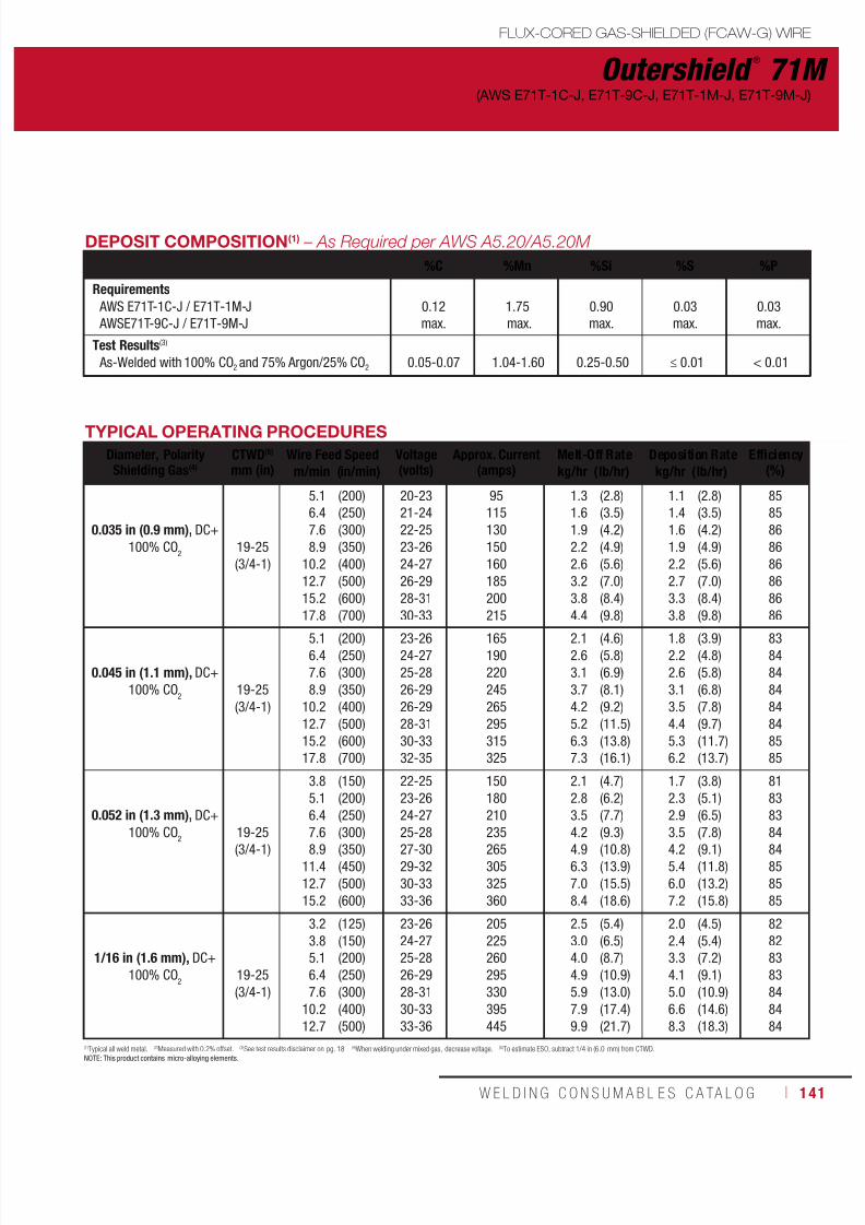
7/18/2019 c110 - Lincoln Electric Consumables 2014
http://slidepdf.com/reader/full/c110-lincoln-electric-consumables-2014 141/511W E L D I N G C O N S U M A B L E S C A TA L O G ı 141
Outershield ®
71M
FLUX-CORED GAS-SHIELDED (FCAW-G) WIRE
(AWS E71T-1C-J, E71T-9C-J, E71T-1M-J, E71T-9M-J)
(1)Typical all weld metal. (2)Measured with 0.2% offset. (3)See test results disclaimer on pg. 18. (4)When welding under mixed gas, decrease voltage. (5)To estimate ESO, subtract 1/4 in (6.0 mm) from CTWD.NOTE: This product contains micro-alloying elements.
DEPOSIT COMPOSITION(1) – As Required per AWS A5.20/A5.20M
%C %Mn %Si %S %P
Requirements
AWS E71T-1C-J / E71T-1M-J AWSE71T-9C-J / E71T-9M-J
0.12max.
1.75 max.
0.90max.
0.03max.
0.03max.
Test Results(3)
As-Welded with 100% CO2 and 75% Argon/25% CO2 0.05-0.07 1.04-1.60 0.25-0.50 ≤ 0.01 < 0.01
TYPICAL OPERATING PROCEDURES
Diameter, PolarityShielding Gas(4)
CTWD(5)
mm (in)Wire Feed Speed Voltage
(volts)Approx. Current
(amps)Melt-Off Rate Deposition Rate Efficiency
(%)m/min (in/min) kg/hr (lb/hr) kg/hr (lb/hr)
0.035 in (0.9 mm), DC+100% CO
219-25(3/4-1)
5.16.47.68.9
10.212.715.217.8
(200)(250)(300)(350)(400)(500)(600)(700)
20-2321-2422-2523-2624-2726-2928-3130-33
95115130150160185200215
1.31.61.92.22.63.23.84.4
(2.8)(3.5)(4.2)(4.9)(5.6)(7.0)(8.4)(9.8)
1.11.41.61.92.22.73.33.8
(2.8)(3.5)(4.2)(4.9)(5.6)(7.0)(8.4)(9.8)
8585868686868686
0.045 in (1.1 mm), DC+100% CO
219-25(3/4-1)
5.16.47.68.9
10.212.715.217.8
(200)(250)(300)(350)(400)(500)(600)(700)
23-2624-2725-2826-2926-2928-3130-3332-35
165190220245265295315325
2.12.63.13.74.25.26.37.3
(4.6)(5.8)(6.9)(8.1)(9.2)(11.5)(13.8)(16.1)
1.82.22.63.13.54.45.36.2
(3.9)(4.8)(5.8)(6.8)(7.8)(9.7)(11.7)(13.7)
8384848484848585
0.052 in (1.3 mm), DC+
100% CO2 19-25(3/4-1)
3.85.16.4
7.68.911.412.715.2
(150)(200)(250)
(300)(350)(450)(500)(600)
22-2523-2624-27
25-2827-3029-3230-3333-36
150180210
235265305325360
2.12.83.5
4.24.96.37.08.4
(4.7)(6.2)(7.7)
(9.3)(10.8)(13.9)(15.5)(18.6)
1.72.32.9
3.54.25.46.07.2
(3.8)(5.1)(6.5)
(7.8)(9.1)(11.8)(13.2)(15.8)
818383
8484858585
1/16 in (1.6 mm), DC+100% CO
219-25(3/4-1)
3.23.85.16.47.6
10.212.7
(125)(150)(200)(250)(300)(400)(500)
23-2624-2725-2826-2928-3130-3333-36
205225260295330395445
2.53.04.04.95.97.99.9
(5.4)(6.5)(8.7)(10.9)(13.0)(17.4)(21.7)
2.02.43.34.15.06.68.3
(4.5)(5.4)(7.2)(9.1)(10.9)(14.6)(18.3)
82828383848484
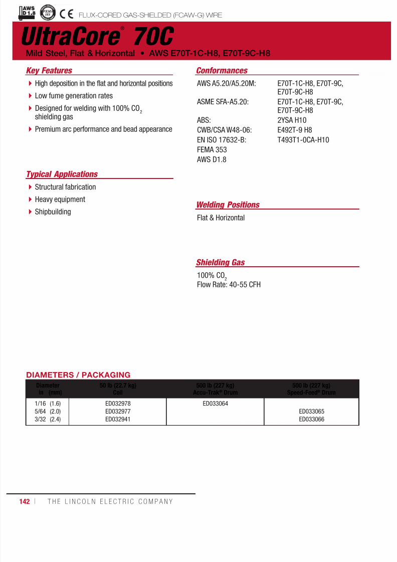
7/18/2019 c110 - Lincoln Electric Consumables 2014
http://slidepdf.com/reader/full/c110-lincoln-electric-consumables-2014 142/511142 ı T H E L I N C O L N E L E C T R I C C O M P A N Y
UltraCore ®
70C
Welding Positions
Typical Applications
Flat & Horizontal
Structural fabrication
Heavy equipment
Shipbuilding
High deposition in the flat and horizontal positions
Low fume generation ratesDesigned for welding with 100% CO
2
shielding gas
Premium arc performance and bead appearance
Conformances
Shielding Gas
100% CO2
Flow Rate: 40-55 CFH
Mild Steel, Flat & Horizontal • AWS E70T-1C-H8, E70T-9C-H8
Key Features
AWS A5.20/A5.20M:
ASME SFA-A5.20:
ABS:
CWB/CSA W48-06:
EN ISO 17632-B:
FEMA 353
AWS D1.8
E70T-1C-H8, E70T-9C,E70T-9C-H8
E70T-1C-H8, E70T-9C,E70T-9C-H8
2YSA H10
E492T-9 H8
T493T1-0CA-H10
FLUX-CORED GAS-SHIELDED (FCAW-G) WIREuctural Welding Code
smic Supplement
DIAMETERS / PACKAGING
Diameter 50 lb (22.7 kg)Coil
500 lb (227 kg)Accu-Trak ® Drum
500 lb (227 kg)Speed-Feed® Drumin (mm)
1/165/643/32
(1.6)(2.0)(2.4)
ED032978ED032977ED032941
ED033064ED033065ED033066

7/18/2019 c110 - Lincoln Electric Consumables 2014
http://slidepdf.com/reader/full/c110-lincoln-electric-consumables-2014 143/511W E L D I N G C O N S U M A B L E S C A TA L O G ı 143
DEPOSIT COMPOSITION(1) – As Required per AWS A5.20/A5.20M
%C %Mn %Si %S %PDiffusible Hydrogen
(mL/100g weld deposit)
Requirements(4)
AWS E70T-1C-H8 & E70T-9C-H8 0.12 max. 1.75 max. 0.90 max. 0.03 max. 0.03 max. 8.0 max.
Typical Results(3)
As-Welded with 100% CO2 0.04-0.05 1.46-1.59 0.54-0.59 ≤ 0.01 ≤ 0.01 5-8
MECHANICAL PROPERTIES(1) – As Required per AWS A5.20/A5.20M
YieldStrength(2)
TensileStrength Elongation
Charpy V-NotchJ (ft•lbf)
MPa (ksi) MPa (ksi) % @ -18°C (0°F) @ -29°C (-20°F)
Requirements(4)
AWS E70T-1C-H8 & E70T-9C-H8
400 (58) min. 480-655 (70-95)
22 min.
27 (20) min. 27 (20) min.
Typical Results(3)
As-Welded with 100% CO2 485-520 (70-75) 555-590 (81-86) 28-30 47-72 (35-53) 28-47 (21-35)
TYPICAL OPERATING PROCEDURES – Flat & Horizontal
Diameter, PolarityShielding Gas
CTWD(5)
mm (in)Wire Feed Speed Voltage
(volts)Approx. Current
(amps)Melt-Off Rate Deposition Rate Efficiency
(%)m/min (in/min) kg/hr (lb/hr) kg/hr (lb/hr)
1/16 in (1.6 mm), DC+100% CO
225 (1)
3.25.16.47.69.5
(125)(200)(250)(300)(375)
23-2724-2825-3027-3128-32
170225260280320
2.43.84.85.77.1
(5.3)(8.4)(10.5)(12.6)(15.7)
2.13.24.14.96.1
(4.7)(7.1)(9.0)(10.8)(13.5)
84 - 89
5/64 in (2.0 mm), DC+100% CO
225 (1)
3.24.45.76.47.68.3
(125)(175)(225)(250)(300)(325)
23-2724-2925-3026-3227-3329-34
230305365385420450
3.85.46.87.79.09.9
(8.4)(11.8)(15.0)(16.9)(19.8)(21.7)
3.24.65.96.57.88.7
(7.1)(10.1)(13.0)(14.3)(17.2)(19.0)
84 - 88
3/32 in (2.4 mm), DC+100% CO
2
25 (1)3.25.1
(125)(200)
26-3327-34
350500
5.48.6
(11.9)(19.0)
4.77.6
(10.3)(16.7)
87 - 89
31 (1 1/4)6.47.68.3
(250)(300)(325)
29-3531-3732-38
570630720
10.613.114.3
(23.3)(28.8)(31.5)
9.411.412.4
(20.8)(25.1)(27.2)
(1)Typical all weld metal. (2)Measured with 0.2% offset. (3)See test results disclaimer on pg. 18. (4) As-Welded with 100% CO2. (5)To estimate ESO, subtract 1/4 in (6.0 mm) from CTWD.
UltraCore ®
70C(AWS E70T-1C-H8, E70T-9C-H8)
FLUX-CORED GAS-SHIELDED (FCAW-G) WIRE

7/18/2019 c110 - Lincoln Electric Consumables 2014
http://slidepdf.com/reader/full/c110-lincoln-electric-consumables-2014 144/511144 ı T H E L I N C O L N E L E C T R I C C O M P A N Y
UltraCore ®
75C FLUX-CORED GAS-SHIELDED (FCAW-G) WIRE
Welding Positions
Typical Applications
Flat & Horizontal
Highly restrained joints
Heaving equipment Mining
Hard to weld base metals
Thick steel sections in structural fabrication
High deposition in the flat and horizontal positions
H4 diffusible hydrogen levels Designed for welding with 100% CO
2
shielding gas
Premium arc performance and bead appearance
Conformances
Shielding Gas
100% CO2
Flow Rate: 40-55 CFH
Mild Steel, Flat & Horizontal • AWS E70T-5C-JH4
Key Features
AWS A5.20/A5.20M: ASME SFA-A5.20:
CWB/CSA W48-06:
EN ISO 17632-B:
E70T-5C-JH4E70T-5C-JH4
E492T-5J H4
T494T5-0CA-H5
DIAMETERS / PACKAGING
Diameter 50 lb (22.7 kg)Coilin (mm)
1/165/643/32
(1.6)(2.0)(2.4)
ED032974ED032975ED032940

7/18/2019 c110 - Lincoln Electric Consumables 2014
http://slidepdf.com/reader/full/c110-lincoln-electric-consumables-2014 145/511W E L D I N G C O N S U M A B L E S C A TA L O G ı 145
UltraCore ®
75C
FLUX-CORED GAS-SHIELDED (FCAW-G) WIRE
(AWS E70T-5C-JH4)
DEPOSIT COMPOSITION(1) – As Required per AWS A5.20/A5.20M
%C %Mn %Si %S %PDiffusible Hydrogen
(mL/100g weld deposit)
Requirements(4) - AWS E70T-5C-JH4 0.12 max. 1.75 max. 0.90 max. 0.03 max. 0.03 max. 4.0 max.
Typical Results(3) - As-Welded with 100% CO2 0.06-0.08 1.51-1.66 0.44-0.53 0.01 0.01 2-4
TYPICAL OPERATING PROCEDURES – Flat & Horizontal
Diameter, PolarityShielding Gas
CTWD(5)
mm (in)Wire Feed Speed Voltage
(volts)Approx. Current
(amps)Melt-Off Rate Deposition Rate Efficiency
(%)m/min (in/min) kg/hr (lb/hr) kg/hr (lb/hr)
1/16 in (1.6 mm), DC+100% CO
2
19-25(3/4-1)
5.16.47.68.9
10.212.7
(200)(250)(300)(350)(400)(500)
29-3431-3632-3733-3833-3835-40
230270295335360415
4.05.05.96.97.99.9
(8.7)(11.0)(13.1)(15.2)(17.4)(21.8)
3.13.84.55.56.37.9
(6.9)(8.5)(10.0)(12.1)(13.9)(17.5)
76-86
5/64 in (2.0 mm), DC+100% CO
225-32
(1-1 1/4)
5.16.47.68.9
10.2
(200)(250)(300)(350)(400)
29-3430-3532-3733-3834-39
295345390425465
5.77.28.6
10.111.5
(12.7)(15.9)(19.0)(22.3)(25.3)
4.86.07.18.59.9
(10.5)(13.2)(15.6)(18.7)(21.8)
82-86
3/32 in (2.4 mm), DC+100% CO
232
(1-3/8)
3.25.16.47.68.3
(125)(200)(250)(300)(325)
23-2827-3229-3431-3632-37
335445500590605
5.58.8
10.913.214.2
(12.2)(19.3)(24.1)(29.2)(31.4)
4.87.69.6
11.812.8
(10.7)(16.7)(21.3)(26.0)(28.3)
87-90
MECHANICAL PROPERTIES(1) – As Required per AWS A5.20/A5.20M
YieldStrength(2)
TensileStrength Elongation
Charpy V-NotchJ (ft•lbf)
MPa (ksi) MPa (ksi) % @ -29°C (-20°F) @ -40°C (-40°F)
Requirements(4) - AWS E70T-5C-JH4 400 (58) min. 480-655 (70-95) 22 min. 27 (20) min. 27 (20) min.
Typical Results(3)
As-Welded with 100% CO2 465-510 (68-74) 545-580 (79-84) 29-32 91-142 (67-105) 53-113 (39-83)
(1)Typical all weld metal. (2)Measured with 0.2% offset. (3)See test results disclaimer on pg. 18. (4) As-Welded with 100% CO2. (5)To estimate ESO, subtract 1/4 in (6.0 mm) from CTWD.
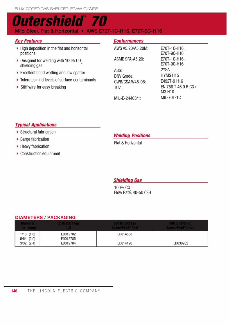
7/18/2019 c110 - Lincoln Electric Consumables 2014
http://slidepdf.com/reader/full/c110-lincoln-electric-consumables-2014 146/511146 ı T H E L I N C O L N E L E C T R I C C O M P A N Y
Outershield ®
70 FLUX-CORED GAS-SHIELDED (FCAW-G) WIRE
Welding Positions
Typical Applications
Flat & Horizontal
Structural fabrication
Barge fabrication
Heavy fabrication
Construction equipment
High deposition in the flat and horizontalpositions
Designed for welding with 100% CO2
shielding gas
Excellent bead wetting and low spatter
Tolerates mild levels of surface contaminants
Stiff wire for easy breaking
Conformances
Shielding Gas
100% CO2
Flow Rate: 40-50 CFH
Mild Steel, Flat & Horizontal • AWS E70T-1C-H16, E70T-9C-H16
Key Features
AWS A5.20/A5.20M:
ASME SFA-A5.20:
ABS:
DNV Grade:
CWB/CSA W48-06:
TUV:
MIL-E-24403/1:
E70T-1C-H16,E70T-9C-H16
E70T-1C-H16,E70T-9C-H16
2YSA
II YMS H15
E492T-9 H16
EN 758 T 46 0 R C3 /M3 H10
MIL-70T-1C
DIAMETERS / PACKAGING
Diameter 50 lb (22.7 kg)Coil
600 lb (272 kg)Speed-Feed® Reel
600 lb (272 kg)Speed-Feed® Drumin (mm)
1/165/643/32
(1.6)(2.0)(2.4)
ED012782ED012785ED012784
ED014588
ED014120 ED030262

7/18/2019 c110 - Lincoln Electric Consumables 2014
http://slidepdf.com/reader/full/c110-lincoln-electric-consumables-2014 147/511W E L D I N G C O N S U M A B L E S C A TA L O G ı 147
Outershield ®
70
FLUX-CORED GAS-SHIELDED (FCAW-G) WIRE
(AWS E70T-1C-H16, E70T-9C-H16)
DEPOSIT COMPOSITION(1) – As Required per AWS A5.20/A5.20M
%C %Mn %Si %S %P
Requirements - AWS E70T-1C, E70T-9C 0.12 max. 1.75 max. 0.90 max. 0.03 max. 0.03 max.
Typical Results(3)
As-Welded with 100% CO2 0.08 1.41-1.43 0.64-0.73 0.01 0.01
MECHANICAL PROPERTIES(1)
– As Required per AWS A5.20/A5.20M
Yield Strength(2) Tensile Strength ElongationCharpy V-Notch
J (ft•lbf)MPa (ksi) MPa (ksi) % @ -18°C (0°F) @ -29°C (-20°F)
Requirements
AWS E70T-1C-H16 AWS E70T-9C-H16
400 (58)min.
485-655(70-95)
22
min.
27 (20) min.
–
– 27 (20) min.
Typical Results(3)
As-Welded with 100% CO2 525-575 (76-83) 620-635 (90-92) 27-28 39-42 (29-31) 31-34 (21-25)
Stress Relieved with 100% CO2
for 1 hr @ 621°C (1150°F) 525 (76) 555 (80) 27-28 27 (20) 24 (18)
TYPICAL OPERATING PROCEDURES
Diameter, PolarityShielding Gas
CTWD(5)
mm (in)Wire Feed Speed Voltage
(volts)Approx. Current
(amps)Melt-Off Rate Deposition Rate Efficiency
(%)m/min (in/min) kg/hr (lb/hr) kg/hr (lb/hr)
1/16 in (1.6 mm), DC+100% CO
225 (1)
3.25.16.47.69.5
(125)(200)(250)(300)(375)
23-2525-2725-2827-2929-31
170235275310365
2.43.84.85.87.2
(5.3)(8.5)(10.6)(2.7)(15.9)
2.13.44.25.06.4
(4.6)(7.6)(9.2)(11.1)(14.0)
8787878788
5/64 in (2.0 mm), DC+100% CO
228
(1-1/8)
3.24.45.76.47.68.3
(125)(175)(225)(250)(300)(325)
23-2626-2827-2929-3130-3231-33
250350375400450470
3.85.46.97.79.29.9
(8.4)(11.8)(15.2)(16.9)(20.2)(21.9)
3.24.55.96.57.98.5
(7.0)(10.0)(13.0)(14.4)(17.4)(18.8)
838586868686
3/32 in (2.4 mm), DC+100% CO
2
32(1-1/4)
3.25.16.47.68.3
(125)(200)(250)(300)(325)
24-2728-3130-3231-3433-35
335455530590615
5.38.5
10.612.713.7
(11.7)(18.6)(23.3)(28.0)(30.3)
4.47.39.2
11.012.0
(9.8)(16.0)(20.2)(24.3)(26.4)
8486878787
(1)Typical all weld metal. (2)Measured with 0.2% offset. (3)See test results disclaimer on pg. 18. (4)To estimate ESO, subtract 1/4 in (6.0 mm) from CTWD.NOTE: This product contains micro-alloying elements. Additional information available upon request.

7/18/2019 c110 - Lincoln Electric Consumables 2014
http://slidepdf.com/reader/full/c110-lincoln-electric-consumables-2014 148/511148 ı T H E L I N C O L N E L E C T R I C C O M P A N Y
Outershield ®
XLH-70
Welding Positions
Typical Applications
Flat & Horizontal
Structural fabrication
General fabrication
Machinery fabrication
Heavy equipment Seismic applications
Meets AWS D1.8 seismic lot waiverrequirements for demand critical welds.
H8 diffusible hydrogen levels - controlled forhigh resistance to hydrogen induced cracking.
High deposition rates and excellent fast followcharacteristics.
Stiff wire enables feeding over long distances.
Tolerates mild levels of surface contaminants.
Designed for welding with CO2 shielding gas.
Conformances
Shielding Gas
100% CO2
Flow Rate: 40-50 CFH
Mild Steel, Flat & Horizontal • AWS E70T-1C-H8, E70T-9C-H8
Key Features
AWS A5.20/A5.20M:
ASME SFA-5.20: ABS:
FEMA 353
AWS D1.8
E70T-1C-H8, E70T-9C-H8
E70T-1C-H8, E70T-9C-H83YSA-H5
FLUX-CORED GAS-SHIELDED (FCAW-G) WIREuctural Welding Code
smic Supplement
DIAMETERS / PACKAGING
Diameter 50 lb (22.7 kg)Coil
500 lb (227 kg)Speed-Feed® Drumin (mm)
3/32 (2.4) ED030236 ED030360
NOTE: Speed-Feed® drums require rotation for proper payoff.

7/18/2019 c110 - Lincoln Electric Consumables 2014
http://slidepdf.com/reader/full/c110-lincoln-electric-consumables-2014 149/511W E L D I N G C O N S U M A B L E S C A TA L O G ı 149
Outershield ®
XLH-70(AWS E70T-1C, E70T-9C)
DEPOSIT COMPOSITION(1) – As Required per AWS A5.20/A5.20M
%C %Mn %Si
Requirements - AWS E70T-1C-H8, E70T-9C-H8 0.12 max. 1.75 max. 0.90 max.
Test Results(3)
As-Welded with 100% CO2 0.06-0.07 1.40-1.60 0.48-0.58
%S %PDiffusible Hydrogen
(mL/100g weld deposit)
Requirements - AWS E70T-1C-H8, E70T-9C-H8 0.03 max. 0.03 max. 8.0 max.
Test Results(3)
As-Welded with 100% CO2 ≤0.01 ≤0.01 3-6
MECHANICAL PROPERTIES(1) – As Required per AWS A5.20/A5.20M
Yield Strength(2) Tensile Strength ElongationCharpy V-Notch
J (ft•lbf)MPa (ksi) MPa (ksi) % @ -18°C (0°F) @ -29°C (-20°F)
Requirements
AWS E70T-1C-H8 AWS E70T-9C-H8
400 (58)min.
480-660(70-95)
22
min.
27 (20) min.
–
– 27 (20) min.
Typical Results(3)
As-Welded with 100% CO2 480-530 (70-77) 570-620 (82-89) 27-30 61-134 (45-99) 42-107 (31-79)
TYPICAL OPERATING PROCEDURES
Diameter, PolarityShielding Gas
CTWD(5)
mm (in)Wire Feed Speed Voltage
(volts)Approx. Current
(amps)Melt-Off Rate Deposition Rate Efficiency
(%)m/min (in/min) kg/hr (lb/hr) kg/hr (lb/hr)
3/32 in. (2.4 mm), DC+100% CO
2
32(1-1/4)
3.85.16.47.68.3
(150)(200)(250)(300)(325)
23-2627-3028-3130-3231-33
345445510570600
6.58.7
10.913.114.2
(14.4)(19.2)(24.0)(28.8)(31.2)
5.67.69.5
11.412.4
(12.4)(16.8)(21.0)(25.2)(27.3)
8687878787
(1)Typical all weld metal. (2)Measured with 0.2% offset. (3)See test results disclaimer on pg. 18. (4)To estimate ESO, subtract 1/4 in (6.0 mm) from CTWD.
FLUX-CORED GAS-SHIELDED (FCAW-G) WIRE
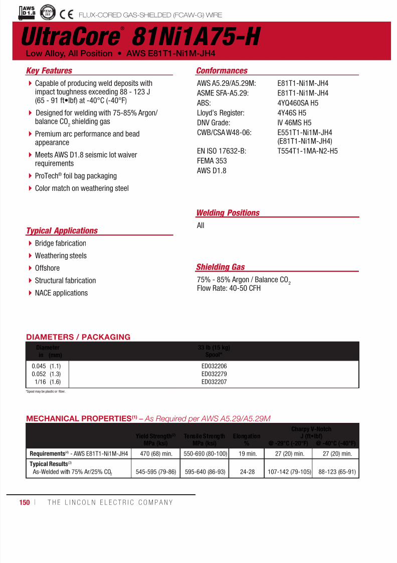
7/18/2019 c110 - Lincoln Electric Consumables 2014
http://slidepdf.com/reader/full/c110-lincoln-electric-consumables-2014 150/511150 ı T H E L I N C O L N E L E C T R I C C O M P A N Y
UltraCore ®
81Ni1A75-H
Welding Positions
Typical Applications All
Bridge fabrication
Weathering steels
Offshore
Structural fabrication
NACE applications
Capable of producing weld deposits withimpact toughness exceeding 88 - 123 J(65 - 91 ft•lbf) at -40°C (-40°F)
Designed for welding with 75-85% Argon/balance CO
2 shielding gas
Premium arc performance and beadappearance
Meets AWS D1.8 seismic lot waiverrequirements
ProTech® foil bag packaging
Color match on weathering steel
Conformances
Shielding Gas
75% - 85% Argon / Balance CO2
Flow Rate: 40-50 CFH
Low Alloy, All Position • AWS E81T1-Ni1M-JH4
Key Features
AWS A5.29/A5.29M:
ASME SFA-A5.29: ABS:
Lloyd’s Register:
DNV Grade:
CWB/CSA W48-06:
EN ISO 17632-B:
FEMA 353
AWS D1.8
E81T1-Ni1M-JH4
E81T1-Ni1M-JH44YQ460SA H5
4Y46S H5
IV 46MS H5
E551T1-Ni1M-JH4(E81T1-Ni1M-JH4)
T554T1-1MA-N2-H5
DIAMETERS / PACKAGING
Diameter 33 lb (15 kg)Spool*in (mm)
0.0450.052
1/16
(1.1)(1.3)
(1.6)
ED032206ED032279
ED032207
MECHANICAL PROPERTIES(1) – As Required per AWS A5.29/A5.29M
Yield Strength(2) Tensile Strength ElongationCharpy V-Notch
J (ft•lbf)MPa (ksi) MPa (ksi) % @ -29°C (-20°F) @ -40°C (-40°F)
Requirements(4) - AWS E81T1-Ni1M-JH4 470 (68) min. 550-690 (80-100) 19 min. 27 (20) min. 27 (20) min.
Typical Results(3)
As-Welded with 75% Ar/25% CO2 545-595 (79-86) 595-640 (86-93) 24-28 107-142 (79-105) 88-123 (65-91)
FLUX-CORED GAS-SHIELDED (FCAW-G) WIREuctural Welding Code
smic Supplement
*Spool may be plastic or fiber.

7/18/2019 c110 - Lincoln Electric Consumables 2014
http://slidepdf.com/reader/full/c110-lincoln-electric-consumables-2014 151/511W E L D I N G C O N S U M A B L E S C A TA L O G ı 151
UltraCore ®
81Ni1A75-H(AWS E81T1-Ni1M-JH4)
DEPOSIT COMPOSITION(1) – As Required per AWS A5.29/A5.29M
%C %Mn %Si %S %P
Requirements(4) - AWS E81T1-Ni1M-JH4 0.12 max. 1.50 max. 0.80 max. 0.030 max. 0.030 max.
Typical Results(3)
As-Welded with 75% Ar/25% CO2 0.04-0.05 1.26-1.36 0.25-0.29 0.006-0.009 0.005-0.008
%Ni %Mo %Cr %VDiffusible Hydrogen
(mL/100g weld deposit)
Requirements(4) - AWS E81T1-Ni1M-JH4 0.80-1.10 0.35 max. 0.15 max. 0.05 max. 4.0 max.
Typical Results(3)
As-Welded with 75% Ar/25% CO2 0.86-0.96 0.01 0.04-0.05 0.02-0.03 2-4
TYPICAL OPERATING PROCEDURES
Diameter, PolarityShielding Gas
CTWD(5)
mm (in)Wire Feed Speed Voltage
(volts)Approx. Current
(amps)Melt-Off Rate Deposition Rate Efficiency
(%)m/min (in/min) kg/hr (lb/hr) kg/hr (lb/hr)
0.045 in (1.1 mm), DC+75%-85% Ar/balance CO
2
25 (1)
4.45.16.47.68.99.5
10.812.112.7
(175)(200)(250)(300)(350)(375)(425)(475)(500)
22-2723-2824-2924-2925-3025-3026-3127-3228-33
140150165190205225245265275
1.82.12.63.13.63.94.44.95.2
(4.0)(4.6)(5.7)(6.8)(8.0)(8.6)(9.7)(10.8)(11.4)
1.61.82.32.73.23.43.84.34.5
(3.5)(4.0)(5.0)(6.0)(7.0)(7.5)(8.5)(9.5)(10.0)
86-88
0.052 in (1.3 mm), DC+75%-85% Ar/
balance CO2
25 (1)
3.84.75.76.47.0
7.68.59.5
10.2
(150)(185)(225)(250)(275)
(300)(335)(375)(400)
22-2723-2823-2824-2924-29
25-3025-3126-3226-33
150165190215235
265275295310
2.02.53.13.43.7
4.14.55.15.4
(4.5)(5.5)(6.7)(7.5)(8.2)
(9.0)(10.0)(11.2)(12.0)
1.82.22.72.93.2
3.54.04.44.7
(3.9)(4.8)(5.9)(6.5)(7.2)
(7.8)(8.7)(9.8)(10.4)
86-88
1/16 in (1.6 mm), DC+75%-85% Ar/balance CO
2
25 (1)
3.84.45.15.76.57.08.38.9
(150)(175)(200)(225)(250)(275)(325)(350)
22-2723-2824-2924-2925-3025-3126-3227-33
200210235265285315335365
2.93.33.84.34.85.36.26.7
(6.3)(7.4)(8.4)(9.5)(10.5)(11.6)(13.7)(14.7)
2.52.93.33.74.24.65.45.8
(5.5)(6.4)(7.3)(8.2)(9.2)(10.1)(11.9)(12.8)
86-88
(1)Typical all weld metal. (2)Measured with 0.2% offset. (3)See test results disclaimer on pg. 18. (4) As-Welded with 75% Argon / 25% CO2. (5)To estimate ESO, subtract 1/4 in (6.0 mm) from CTWD.NOTE 1 : FEMA and AWS D1.8 structural steel seismic supplement test d ata can be found on this product at www.lincolnelectric.com. NOTE 2: This product contains micro-alloying elements. Additional information available upon request.
FLUX-CORED GAS-SHIELDED (FCAW-G) WIRE
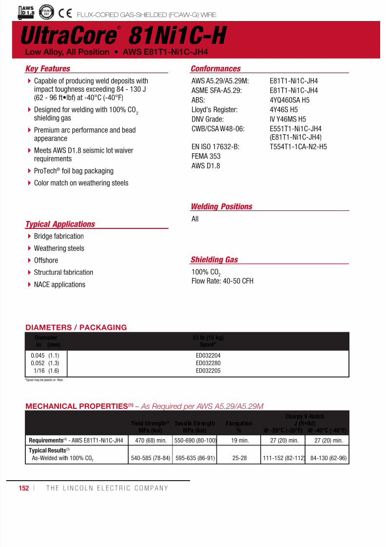
7/18/2019 c110 - Lincoln Electric Consumables 2014
http://slidepdf.com/reader/full/c110-lincoln-electric-consumables-2014 152/511152 ı T H E L I N C O L N E L E C T R I C C O M P A N Y
UltraCore ®
81Ni1C-H
Welding Positions
Typical Applications All
Bridge fabrication
Weathering steels
Offshore
Structural fabrication
NACE applications
Capable of producing weld deposits withimpact toughness exceeding 84 - 130 J(62 - 96 ft•lbf) at -40°C (-40°F)
Designed for welding with 100% CO2
shielding gas
Premium arc performance and beadappearance
Meets AWS D1.8 seismic lot waiverrequirements
ProTech® foil bag packaging
Color match on weathering steels
Conformances
Shielding Gas
100% CO2
Flow Rate: 40-50 CFH
Low Alloy, All Position • AWS E81T1-Ni1C-JH4
Key Features
AWS A5.29/A5.29M:
ASME SFA-A5.29: ABS:
Lloyd’s Register:
DNV Grade:
CWB/CSA W48-06:
EN ISO 17632-B:
FEMA 353
AWS D1.8
E81T1-Ni1C-JH4
E81T1-Ni1C-JH44YQ460SA H5
4Y46S H5
IV Y46MS H5
E551T1-Ni1C-JH4(E81T1-Ni1C-JH4)
T554T1-1CA-N2-H5
DIAMETERS / PACKAGING
Diameter 33 lb (15 kg)Spool*in (mm)
0.0450.0521/16
(1.1)(1.3)(1.6)
ED032204ED032280ED032205
MECHANICAL PROPERTIES(1) – As Required per AWS A5.29/A5.29M
Yield Strength(2) Tensile Strength ElongationCharpy V-Notch
J (ft•lbf)MPa (ksi) MPa (ksi) % @ -29°C (-20°F) @ -40°C (-40°F)
Requirements(4) - AWS E81T1-Ni1C-JH4 470 (68) min. 550-690 (80-100) 19 min. 27 (20) min. 27 (20) min.
Typical Results(3)
As-Welded with 100% CO2 540-585 (78-84) 595-635 (86-91) 25-28 111-152 (82-112) 84-130 (62-96)
FLUX-CORED GAS-SHIELDED (FCAW-G) WIREuctural Welding Code
smic Supplement
*Spool may be plastic or fiber.

7/18/2019 c110 - Lincoln Electric Consumables 2014
http://slidepdf.com/reader/full/c110-lincoln-electric-consumables-2014 153/511W E L D I N G C O N S U M A B L E S C A TA L O G ı 153
UltraCore ®
81Ni1C-H(AWS E81T1-Ni1C-JH4)
DEPOSIT COMPOSITION(1) – As Required per AWS A5.29/A5.29M
%C %Mn %Si %S %P
Requirements(4) - AWS E81T1-Ni1C-JH4 0.12 max. 1.50 max. 0.80 max. 0.030 max. 0.030 max.
Typical Results(3)
As-Welded with 100% CO2 0.04-0.05 1.24-1.34 0.27-0.31 0.006-0.007 0.007-0.009
%Ni %Mo %Cr %VDiffusible Hydrogen
(mL/100g weld deposit)
Requirements(4) - AWS E81T1-Ni1C-JH4 0.80-1.10 0.35 max. 0.15 max. 0.05 max. 4.0max.
Typical Results(3)
As-Welded with 100% CO2
0.88-0.99 0.01 0.04-0.05 0.02-0.03 3-4
TYPICAL OPERATING PROCEDURES
Diameter, PolarityShielding Gas
CTWD(5)
mm (in)Wire Feed Speed Voltage
(volts)Approx. Current
(amps)Melt-Off Rate Deposition Rate Efficiency
(%)m/min (in/min) kg/hr (lb/hr) kg/hr (lb/hr)
0.045 in (1.1 mm), DC+100% CO
2
25 (1)
4.45.16.47.6
8.99.5
10.812.112.7
(175)(200)(250)(300)
(350)(375)(425)(475)(500)
23-2824-2925-3025-30
26-3126-3127-3228-3329-34
140150165190
205225245265275
1.82.12.63.1
3.63.94.44.95.2
(4.0)(4.6)(5.7)(6.8)
(8.0)(8.6)(9.7)(10.8)(11.4)
1.61.82.32.7
3.23.43.84.34.5
(3.5)(4.0)(5.0)(6.0)
(7.0)(7.5)(8.5)(9.5)(10.0)
86-88
0.052 in (1.3 mm), DC+100% CO
2
25 (1)
3.84.75.76.47.07.68.59.5
10.2
(150)(185)(225)(250)(275)(300)(335)(375)(400)
23-2824-2924-2925-3025-3026-3126-3127-3227-34
150165190215235255275295310
2.02.53.13.43.74.14.55.15.4
(4.5)(5.5)(6.7)(7.5)(8.2)(9.0)(10.0)(11.2)(12.0)
1.82.22.72.93.23.54.04.44.7
(3.9)(4.8)(5.9)(6.5)(7.2)(7.8)(8.7)(9.8)(10.4)
86-88
1/16 in (1.6 mm), DC+100% CO
2
25 (1)
3.84.45.15.76.47.08.38.9
(150)(175)(200)(225)(250)(275)(325)(350)
24-2924-3025-3025-3126-3126-3227-3228-34
200210235265285305335365
2.93.33.84.34.85.36.26.7
(6.3)(7.4)(8.4)(9.5)(10.5)(11.6)(13.7)(14.7)
2.52.93.33.74.24.65.45.8
(5.5)(6.4)(7.3)(8.2)(9.2)(10.1)(11.9)(12.8)
86-88
(1)Typical all weld metal. (2)Measured with 0.2% offset. (3)See test results disclaimer on pg. 18. (4) As-Welded with 100% CO2. (5)To estimate ESO, subtract 1/4 in (6.0 mm) from CTWD.NOTE 1: FEMA and AWS D1.8 structural steel seismic supplement test data can be found on this product at www.lincolnelectric.com. NOTE 2: This product contains micro-alloying elements. Additional information available upon request.
FLUX-CORED GAS-SHIELDED (FCAW-G) WIRE
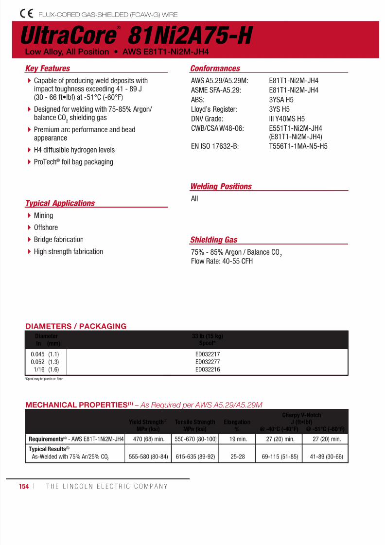
7/18/2019 c110 - Lincoln Electric Consumables 2014
http://slidepdf.com/reader/full/c110-lincoln-electric-consumables-2014 154/511154 ı T H E L I N C O L N E L E C T R I C C O M P A N Y
UltraCore ®
81Ni2A75-H FLUX-CORED GAS-SHIELDED (FCAW-G) WIRE
Welding Positions
Typical Applications All
Mining
Offshore
Bridge fabrication
High strength fabrication
Capable of producing weld deposits withimpact toughness exceeding 41 - 89 J(30 - 66 ft•lbf) at -51°C (-60°F)
Designed for welding with 75-85% Argon/balance CO
2 shielding gas
Premium arc performance and beadappearance
H4 diffusible hydrogen levels
ProTech® foil bag packaging
Conformances
Shielding Gas
75% - 85% Argon / Balance CO2
Flow Rate: 40-55 CFH
Low Alloy, All Position • AWS E81T1-Ni2M-JH4
Key Features
AWS A5.29/A5.29M:
ASME SFA-A5.29: ABS:
Lloyd’s Register:
DNV Grade:
CWB/CSA W48-06:
EN ISO 17632-B:
E81T1-Ni2M-JH4
E81T1-Ni2M-JH43YSA H5
3YS H5
III Y40MS H5
E551T1-Ni2M-JH4(E81T1-Ni2M-JH4)
T556T1-1MA-N5-H5
DIAMETERS / PACKAGING
Diameter 33 lb (15 kg)Spool*in (mm)
0.0450.0521/16
(1.1)(1.3)(1.6)
ED032217ED032277ED032216
MECHANICAL PROPERTIES(1) – As Required per AWS A5.29/A5.29M
Yield Strength(2) Tensile Strength ElongationCharpy V-Notch
J (ft•lbf)MPa (ksi) MPa (ksi) % @ -40°C (-40°F) @ -51°C (-60°F)
Requirements(4) - AWS E81T-1Ni2M-JH4 470 (68) min. 550-670 (80-100) 19 min. 27 (20) min. 27 (20) min.
Typical Results(3)
As-Welded with 75% Ar/25% CO2 555-580 (80-84) 615-635 (89-92) 25-28 69-115 (51-85) 41-89 (30-66)
*Spool may be plastic or fiber.

7/18/2019 c110 - Lincoln Electric Consumables 2014
http://slidepdf.com/reader/full/c110-lincoln-electric-consumables-2014 155/511W E L D I N G C O N S U M A B L E S C A TA L O G ı 155
UltraCore ®
81Ni2A75-H
FLUX-CORED GAS-SHIELDED (FCAW-G) WIRE
(AWS E81T1-Ni2M-JH4)
DEPOSIT COMPOSITION(1) – As Required per AWS A5.29/A5.29M
%C %Mn %Si %S
Requirements(4) - AWS E81T1-Ni2M-JH4 0.12 max. 1.50 max. 0.80 max. 0.030 max.
Typical Results(3)
As-Welded with 75% Ar/25% CO2 0.04-0.05 0.93-1.05 0.25-0.28 0.005-0.006
%P %NiDiffusible Hydrogen
(mL/100g weld deposit)
Requirements(4) - AWS E81T1-Ni2M-JH4 0.030 max. 1.75-2.75 4.0 max.
Typical Results(3)
As-Welded with 75% Ar/25% CO2
0.006-0.008 2.01-2.13 3-4
TYPICAL OPERATING PROCEDURES
Diameter, PolarityShielding Gas
CTWD(5)
mm (in)Wire Feed Speed Voltage
(volts)Approx. Current
(amps)Melt-Off Rate Deposition Rate Efficiency
(%)m/min (in/min) kg/hr (lb/hr) kg/hr (lb/hr)
0.045 in (1.1 mm), DC+75%-85% Ar/balance CO
2
25 (1)
4.45.16.47.68.99.5
10.812.112.7
(175)(200)(250)(300)(350)(375)(425)(475)(500)
21-2622-2722-2723-2824-2924-2925-3026-3127-32
140150165190205225245265275
1.82.12.63.13.63.94.44.95.2
(4.0)(4.6)(5.7)(6.8)(8.0)(8.6)(9.7)(10.8)(11.4)
1.61.82.32.73.23.43.84.34.5
(3.5)(4.0)(5.0)(6.0)(7.0)(7.5)(8.5)(9.5)(10.0)
86-88
0.052 in (1.3 mm), DC+75%-85% Ar/
balance CO2
25 (1)
3.84.75.76.47.0
7.68.59.5
10.2
(150)(185)(225)(250)(275)
(300)(335)(375)(400)
21-2622-2722-2723-2823-28
24-2924-3025-3125-32
150165190215235
255275295310
2.02.53.13.43.7
4.14.55.15.4
(4.5)(5.5)(6.7)(7.5)(8.2)
(9.0)(10.0)(11.2)(12.0)
1.82.22.72.93.2
3.54.04.44.7
(3.9)(4.8)(5.9)(6.5)(7.2)
(7.8)(8.7)(9.8)(10.4)
86-88
1/16 in (1.6 mm), DC+75%-85% Ar/balance CO
2
25 (1)
3.84.45.15.76.47.08.38.9
(150)(175)(200)(225)(250)(275)(325)(350)
21-2721-2822-2923-3024-3124-3224-3225-33
200210235265285315335365
2.93.33.84.34.85.36.26.7
(6.3)(7.4)(8.4)(9.5)(10.5)(11.6)(13.7)(14.7)
2.52.93.33.74.24.65.45.8
(5.5)(6.4)(7.3)(8.2)(9.2)(10.1)(11.9)(12.8)
86-88
(1)Typical all weld metal. (2)Measured with 0.2% offset. (3)See test results disclaimer on pg. 18. (4) As-Welded with 75% Argon / 25% CO2. (5)To estimate ESO, subtract 1/4 in (6.0 mm) from CTWD.

7/18/2019 c110 - Lincoln Electric Consumables 2014
http://slidepdf.com/reader/full/c110-lincoln-electric-consumables-2014 156/511156 ı T H E L I N C O L N E L E C T R I C C O M P A N Y
UltraCore ®
81Ni2C-H FLUX-CORED GAS-SHIELDED (FCAW-G) WIRE
Welding Positions
Typical Applications
All, except vertical down
Mining
Offshore
Bridge fabrication
High strength fabrication
Capable of producing weld deposits withimpact toughness exceeding 54 - 84 J(40 - 62 ft•lbf) at -51°C (-60°F)
Designed for welding with 100% CO2
shielding gas
Premium arc performance and beadappearance
H4 diffusible hydrogen levels
ProTech® foil bag packaging
Conformances
Shielding Gas
100% CO2
Flow Rate: 40-50 CFH
Low Alloy, All Position • AWS E81T1-Ni2C-JH4
Key Features
AWS A5.29/A5.29M:
ASME SFA-A5.29: ABS:
Lloyd’s Register:
DNV Grade:
CWB/CSA W48-06:
EN ISO 17632-B:
E81T1-Ni2C-JH4
E81T1-Ni2C-JH43YSA H5
3YS H5
III Y40MS H5
E551T1-Ni2C-JH4(E81T1-Ni2C-JH4)
T556T1-1CA-N5-H5
DIAMETERS / PACKAGING
Diameter 33 lb (15 kg)Spool*in (mm)
0.0450.0521/16
(1.1)(1.3)(1.6)
ED032215ED032278ED032214
MECHANICAL PROPERTIES(1) – As Required per AWS A5.29/A5.29M
Yield Strength(2) Tensile Strength ElongationCharpy V-Notch
J (ft•lbf)MPa (ksi) MPa (ksi) % @ -40°C (-40°F) @ -51°C (-60°F)
Requirements(4) - AWS E81T1-Ni2C-JH4 470 (68) min. 550-670 (80-100) 19 min. 27 (20) min. 27 (20) min.
Typical Results(3)
As-Welded with 100% CO2
555-600 (80-86) 615-650 (89-94) 26-28 76-111 (56-82) 54-84 (40-62)
*Spool may be plastic or fiber.
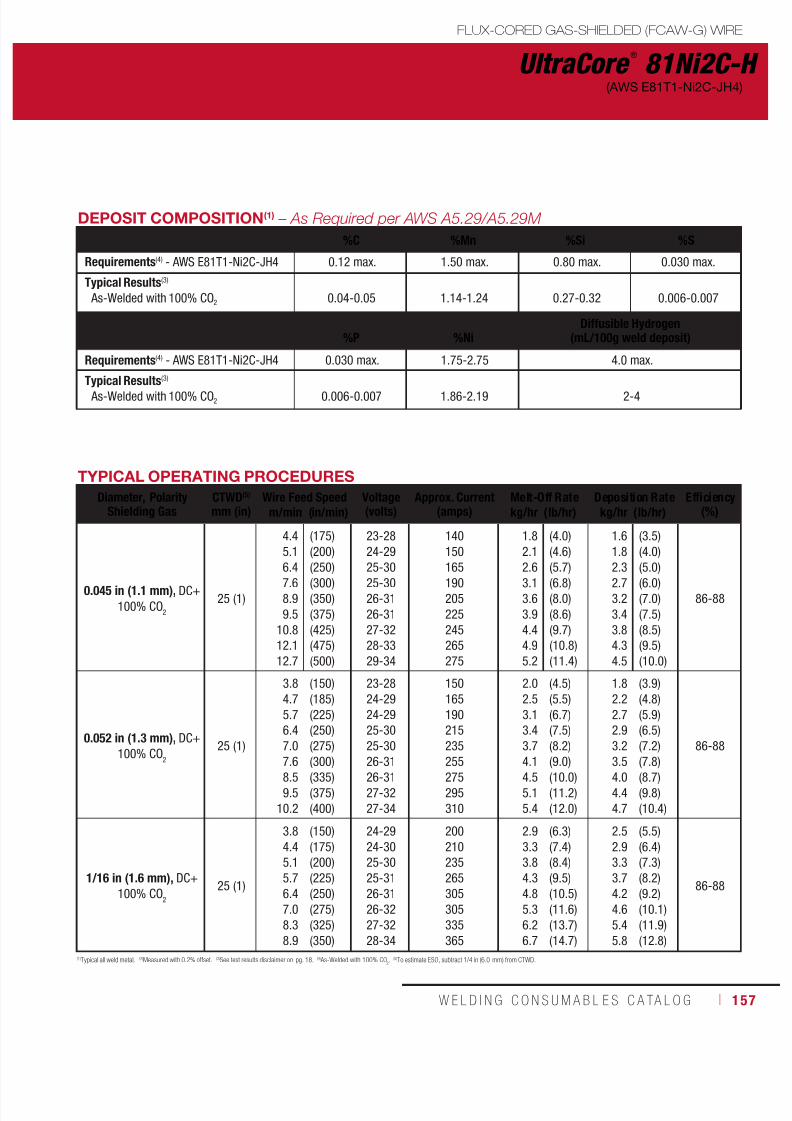
7/18/2019 c110 - Lincoln Electric Consumables 2014
http://slidepdf.com/reader/full/c110-lincoln-electric-consumables-2014 157/511W E L D I N G C O N S U M A B L E S C A TA L O G ı 157
UltraCore ®
81Ni2C-H
FLUX-CORED GAS-SHIELDED (FCAW-G) WIRE
(AWS E81T1-Ni2C-JH4)
DEPOSIT COMPOSITION(1) – As Required per AWS A5.29/A5.29M
%C %Mn %Si %S
Requirements(4) - AWS E81T1-Ni2C-JH4 0.12 max. 1.50 max. 0.80 max. 0.030 max.
Typical Results(3)
As-Welded with 100% CO2 0.04-0.05 1.14-1.24 0.27-0.32 0.006-0.007
%P %NiDiffusible Hydrogen
(mL/100g weld deposit)
Requirements(4) - AWS E81T1-Ni2C-JH4 0.030 max. 1.75-2.75 4.0 max.
Typical Results(3)
As-Welded with 100% CO2 0.006-0.007 1.86-2.19 2-4
TYPICAL OPERATING PROCEDURES
Diameter, PolarityShielding Gas
CTWD(5)
mm (in)Wire Feed Speed Voltage
(volts)Approx. Current
(amps)Melt-Off Rate Deposition Rate Efficiency
(%)m/min (in/min) kg/hr (lb/hr) kg/hr (lb/hr)
0.045 in (1.1 mm), DC+100% CO
2
25 (1)
4.45.16.47.68.99.5
10.812.112.7
(175)(200)(250)(300)(350)(375)(425)(475)(500)
23-2824-2925-3025-3026-3126-3127-3228-3329-34
140150165190205225245265275
1.82.12.63.13.63.94.44.95.2
(4.0)(4.6)(5.7)(6.8)(8.0)(8.6)(9.7)(10.8)(11.4)
1.61.82.32.73.23.43.84.34.5
(3.5)(4.0)(5.0)(6.0)(7.0)(7.5)(8.5)(9.5)(10.0)
86-88
0.052 in (1.3 mm), DC+100% CO
2
25 (1)
3.84.75.76.47.0
7.68.59.5
10.2
(150)(185)(225)(250)(275)
(300)(335)(375)(400)
23-2824-2924-2925-3025-30
26-3126-3127-3227-34
150165190215235
255275295310
2.02.53.13.43.7
4.14.55.15.4
(4.5)(5.5)(6.7)(7.5)(8.2)
(9.0)(10.0)(11.2)(12.0)
1.82.22.72.93.2
3.54.04.44.7
(3.9)(4.8)(5.9)(6.5)(7.2)
(7.8)(8.7)(9.8)(10.4)
86-88
1/16 in (1.6 mm), DC+100% CO
2
25 (1)
3.84.45.15.76.47.08.38.9
(150)(175)(200)(225)(250)(275)(325)(350)
24-2924-3025-3025-3126-3126-3227-3228-34
200210235265305305335365
2.93.33.84.34.85.36.26.7
(6.3)(7.4)(8.4)(9.5)(10.5)(11.6)(13.7)(14.7)
2.52.93.33.74.24.65.45.8
(5.5)(6.4)(7.3)(8.2)(9.2)(10.1)(11.9)(12.8)
86-88
(1)Typical all weld metal. (2)Measured with 0.2% offset. (3)See test results disclaimer on pg. 18. (4) As-Welded with 100% CO2. (5)To estimate ESO, subtract 1/4 in (6.0 mm) from CTWD.
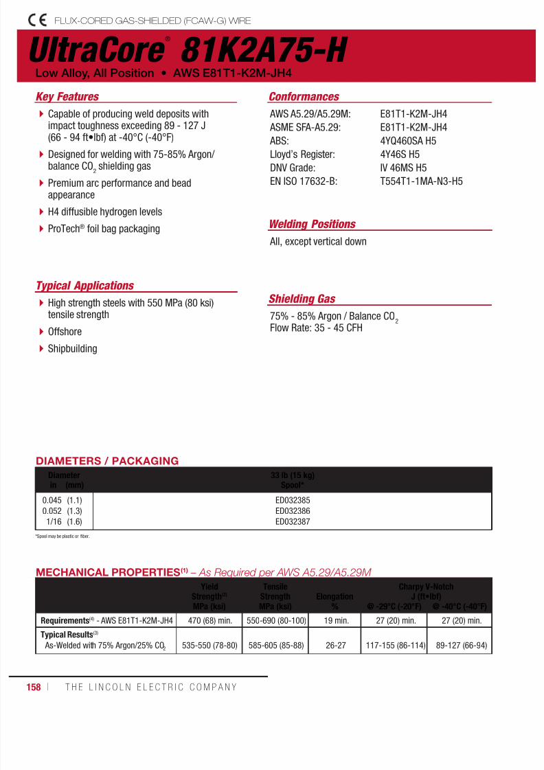
7/18/2019 c110 - Lincoln Electric Consumables 2014
http://slidepdf.com/reader/full/c110-lincoln-electric-consumables-2014 158/511158 ı T H E L I N C O L N E L E C T R I C C O M P A N Y
UltraCore ®
81K2A75-H FLUX-CORED GAS-SHIELDED (FCAW-G) WIRE
Welding Positions
Typical Applications
All, except vertical down
High strength steels with 550 MPa (80 ksi)tensile strength
Offshore
Shipbuilding
Capable of producing weld deposits withimpact toughness exceeding 89 - 127 J(66 - 94 ft•lbf) at -40°C (-40°F)
Designed for welding with 75-85% Argon/balance CO
2 shielding gas
Premium arc performance and beadappearance
H4 diffusible hydrogen levels
ProTech® foil bag packaging
Conformances
Shielding Gas
75% - 85% Argon / Balance CO2
Flow Rate: 35 - 45 CFH
Low Alloy, All Position • AWS E81T1-K2M-JH4
Key Features
AWS A5.29/A5.29M:
ASME SFA-A5.29: ABS:
Lloyd’s Register:
DNV Grade:
EN ISO 17632-B:
E81T1-K2M-JH4
E81T1-K2M-JH44YQ460SA H5
4Y46S H5
IV 46MS H5
T554T1-1MA-N3-H5
DIAMETERS / PACKAGING
Diameter 33 lb (15 kg)Spool*in (mm)
0.0450.0521/16
(1.1)(1.3)(1.6)
ED032385ED032386ED032387
MECHANICAL PROPERTIES(1) – As Required per AWS A5.29/A5.29M
YieldStrength(2)
TensileStrength Elongation
Charpy V-NotchJ (ft•lbf)
MPa (ksi) MPa (ksi) % @ -29°C (-20°F) @ -40°C (-40°F)
Requirements(4) - AWS E81T1-K2M-JH4 470 (68) min. 550-690 (80-100) 19 min. 27 (20) min. 27 (20) min.
Typical Results(3)
As-Welded with 75% Argon/25% CO2 535-550 (78-80) 585-605 (85-88) 26-27 117-155 (86-114) 89-127 (66-94)
*Spool may be plastic or fiber.

7/18/2019 c110 - Lincoln Electric Consumables 2014
http://slidepdf.com/reader/full/c110-lincoln-electric-consumables-2014 159/511W E L D I N G C O N S U M A B L E S C A TA L O G ı 159
UltraCore ®
81K2A75-H
FLUX-CORED GAS-SHIELDED (FCAW-G) WIRE
(AWS E81T1-K2M-JH4)
DEPOSIT COMPOSITION(1) – As Required per AWS A5.29/A5.29M
%C %Mn %Si %S %P
Requirements(4) - AWS E81T1-K2M-JH4 0.15 max. 0.50-1.75 0.80 max. 0.030 max. 0.030 max.
Typical Results(3)
As-Welded with 75% Ar/25% CO2 0.04-0.05 0.98-1.09 0.25-0.28 0.006-0.009 0.005-0.008
%Ni %Cr %Mo %VDiffusible Hydrogen
(mL/100g weld deposit)
Requirements(4) - AWS E81T1-K2M-JH4 1.00-2.00 0.15 max. 0.35 max. 0.05 max. 4 max.
Typical Results(3)
As-Welded with 75% Ar/25% CO2
1.40-1.63 0.03-0.04 0.01-0.02 0.02-0.03 2-4
TYPICAL OPERATING PROCEDURES
Diameter, PolarityShielding Gas
CTWD(5)
mm (in)Wire Feed Speed Voltage
(volts)Approx. Current
(amps)Melt-Off Rate Deposition Rate Efficiency
(%)m/min (in/min) kg/hr (lb/hr) kg/hr (lb/hr)
0.045 in (1.1 mm), DC+75%-85% Ar/balance CO
2
25 (1)
4.45.16.4
7.68.99.5
10.812.112.7
(175)(200)(250)
(300)(350)(375)(425)(475)(500)
22-2723-2824-29
24-2925-3025-3026-3127-3228-33
140150165
190205225245265275
1.82.12.6
3.13.63.94.44.95.2
(4.0)(4.6)(5.7)
(6.8)(8.0)(8.6)(9.7)(10.8)(11.4)
1.61.82.3
2.73.23.43.84.34.5
(3.5)(4.0)(5.0)
(6.0)(7.0)(7.5)(8.5)(9.5)(10.0)
86-88
0.052 in (1.3 mm), DC+75%-85% Ar/balance CO
2
25 (1)
3.84.75.76.46.97.68.59.5
10.2
(150)(185)(225)(250)(275)(300)(335)(375)(400)
22-2723-2823-2824-2924-2925-3025-3126-3226-33
150165190215235255275295310
2.02.53.13.43.74.14.55.15.4
(4.5)(5.5)(6.7)(7.5)(8.2)(9.0)(10.0)(11.2)(12.0)
1.82.22.72.93.23.54.04.44.7
(3.9)(4.8)(5.9)(6.5)(7.2)(7.8)(8.7)(9.8)(10.4)
86-88
1/16 in (1.6 mm), DC+75%-85% Ar/balance CO
2
25 (1)
3.84.45.15.76.46.98.38.9
(150)(175)(200)(225)(250)(275)(325)(350)
22-2723-2824-2924-2925-3025-3126-3227-33
200210235265285315335365
2.93.33.84.34.85.36.26.7
(6.3)(7.4)(8.4)(9.5)(10.5)(11.6)(13.7)(14.7)
2.52.93.33.74.24.65.45.8
(5.5)(6.4)(7.3)(8.2)(9.2)(10.1)(11.9)(12.8)
86-88
(1)Typical all weld metal. (2)Measured with 0.2% offset. (3)See test results disclaimer on pg. 18. (4) As-Welded with 75% Argon/25% CO2. (5)To estimate ESO, subtract 1/4 in (6.0 mm) from CTWD.
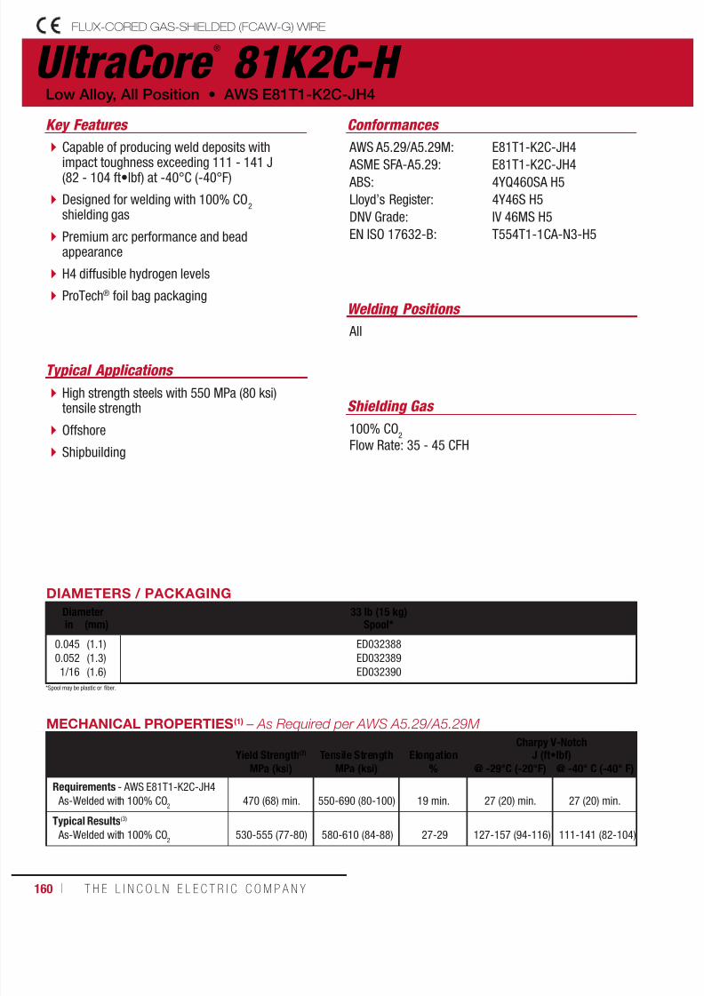
7/18/2019 c110 - Lincoln Electric Consumables 2014
http://slidepdf.com/reader/full/c110-lincoln-electric-consumables-2014 160/511160 ı T H E L I N C O L N E L E C T R I C C O M P A N Y
UltraCore ®
81K2C-H FLUX-CORED GAS-SHIELDED (FCAW-G) WIRE
Welding Positions
Typical Applications
All
High strength steels with 550 MPa (80 ksi)tensile strength
Offshore
Shipbuilding
Capable of producing weld deposits withimpact toughness exceeding 111 - 141 J(82 - 104 ft•lbf) at -40°C (-40°F)
Designed for welding with 100% CO2
shielding gas
Premium arc performance and beadappearance
H4 diffusible hydrogen levels
ProTech® foil bag packaging
Conformances
Shielding Gas
100% CO2
Flow Rate: 35 - 45 CFH
Low Alloy, All Position • AWS E81T1-K2C-JH4
Key Features
AWS A5.29/A5.29M:
ASME SFA-A5.29: ABS:
Lloyd’s Register:
DNV Grade:
EN ISO 17632-B:
E81T1-K2C-JH4
E81T1-K2C-JH44YQ460SA H5
4Y46S H5
IV 46MS H5
T554T1-1CA-N3-H5
DIAMETERS / PACKAGING
Diameter 33 lb (15 kg)Spool*in (mm)
0.0450.0521/16
(1.1)(1.3)(1.6)
ED032388ED032389ED032390
MECHANICAL PROPERTIES(1) – As Required per AWS A5.29/A5.29M
Yield Strength(2) Tensile Strength ElongationCharpy V-Notch
J (ft•lbf)
MPa (ksi) MPa (ksi) % @ -29°C (-20°F) @ -40° C (-40° F)
Requirements - AWS E81T1-K2C-JH4 As-Welded with 100% CO
2
470 (68) min.
550-690 (80-100)
19 min.
27 (20) min.
27 (20) min.
Typical Results(3)
As-Welded with 100% CO2
530-555 (77-80) 580-610 (84-88) 27-29 127-157 (94-116) 111-141 (82-104)
*Spool may be plastic or fiber.

7/18/2019 c110 - Lincoln Electric Consumables 2014
http://slidepdf.com/reader/full/c110-lincoln-electric-consumables-2014 161/511W E L D I N G C O N S U M A B L E S C A TA L O G ı 161
DEPOSIT COMPOSITION(1) – As Required per AWS A5.29/A5.29M
%C %Mn %Si %S %P
Requirements(4) - AWS E81T1-K2C-JH4 0.15 max. 0.50-1.75 0.80 max. 0.030 max. 0.030 max.
Typical Results(3)
As-Welded with 100% CO2
0.04 1.08-1.15 0.23-0.31 0.005-0.009 0.005-0.009
%Ni %Cr %Mo %VDiffusible Hydrogen
(mL/100g weld deposit)
Requirements(4) - AWS E81T1-K2C-JH4 1.00-2.00 0.15 max. 0.35 max. 0.05 max. 4.0 max.
Typical Results(3)
As-Welded with 100% CO2
1.30-1.62 0.03-0.05 0.01-0.02 0.01-0.02 2-3
UltraCore ®
81K2C-H
FLUX-CORED GAS-SHIELDED (FCAW-G) WIRE
(AWS E81T1-K2C-JH4)
TYPICAL OPERATING PROCEDURES
Diameter, PolarityShielding Gas
CTWD(5)
mm (in)Wire Feed Speed Voltage
(volts)Approx. Current
(amps)Melt-Off Rate Deposition Rate Efficiency
(%)m/min (in/min) kg/hr (lb/hr) kg/hr (lb/hr)
0.045 in (1.1 mm), DC+100% CO
2
25 (1)
4.45.16.47.68.99.5
10.812.112.7
(175)(200)(250)(300)(350)(375)(425)(475)(500)
23-2824-2925-3025-3026-3126-3127-3228-3329-34
140150165190205225245265275
1.82.12.63.13.63.94.44.95.2
(4.0)(4.6)(5.7)(6.8)(8.0)(8.6)(9.7)(10.8)(11.4)
1.61.82.32.73.23.43.84.34.5
(3.5)(4.0)(5.0)(6.0)(7.0)(7.5)(8.5)(9.5)(10.0)
86-88
0.052 in (1.3 mm), DC+100% CO
2
25 (1)
3.84.75.76.46.9
7.68.59.5
10.2
(150)(185)(225)(250)(275)
(300)(335)(375)(400)
23-2824-2924-2925-3025-30
26-3126-3127-3227-34
150165190215235
255275295310
2.02.53.13.43.7
4.14.55.15.4
(4.5)(5.5)(6.7)(7.5)(8.2)
(9.0)(10.0)(11.2)(12.0)
1.82.22.72.93.2
3.54.04.44.7
(3.9)(4.8)(5.9)(6.5)(7.2)
(7.8)(8.7)(9.8)(10.4)
86-88
1/16 in (1.6 mm), DC+100% CO
2
25 (1)
3.84.45.15.76.46.98.38.9
(150)(175)(200)(225)(250)(275)(325)(350)
24-2924-3025-3025-3126-3126-3227-3228-34
200210235265285305335365
2.93.33.84.34.85.36.26.7
(6.3)(7.4)(8.4)(9.5)(10.5)(11.6)(13.7)(14.7)
2.52.93.33.74.24.65.45.8
(5.5)(6.4)(7.3)(8.2)(9.2)(10.1)(11.9)(12.8)
86-88
(1)Typical all weld metal. (2)Measured with 0.2% offset. (3)See test results disclaimer on pg. 18. (4) As-Welded with 100% CO2. (5)To estimate ESO, subtract 1/4 in (6.0 mm) from CTWD.

7/18/2019 c110 - Lincoln Electric Consumables 2014
http://slidepdf.com/reader/full/c110-lincoln-electric-consumables-2014 162/511162 ı T H E L I N C O L N E L E C T R I C C O M P A N Y
Outershield ®
91K2-H FLUX-CORED GAS-SHIELDED (FCAW-G) WIRE
Welding Positions
Typical Applications
All, except vertical down
For applications requiring high strength weldmetal, such as HY-80, HSLA 80 and ASTM A710 steels
Designed for welding with 75-95% Argon/balance CO
2 shielding gas
Capable of producing weld deposits withtensile strength exceeding 620 MPa (90 ksi)
Use on high strength, low alloy steelapplications
H8 diffusible hydrogen levels
Conformances
Shielding Gas
75 - 95% Argon / Balance CO2
Flow Rate: 35 - 45 CFH
Low Alloy, All Position • AWS E91T1-K2M-H8
Key Features
AWS A5.29/A5.29M: ASME SFA-A5.29: ABS:
E91T1-K2M-H8E91T1-K2M-H8E91T1-K2M-H8
DIAMETERS / PACKAGING
Diameter 25 lb (11.3 kg) Plastic Spool(Vacuum Sealed Foil Bag)in (mm)
0.0450.0521/16
(1.1)(1.3)(1.6)
ED030975ED030976ED030977
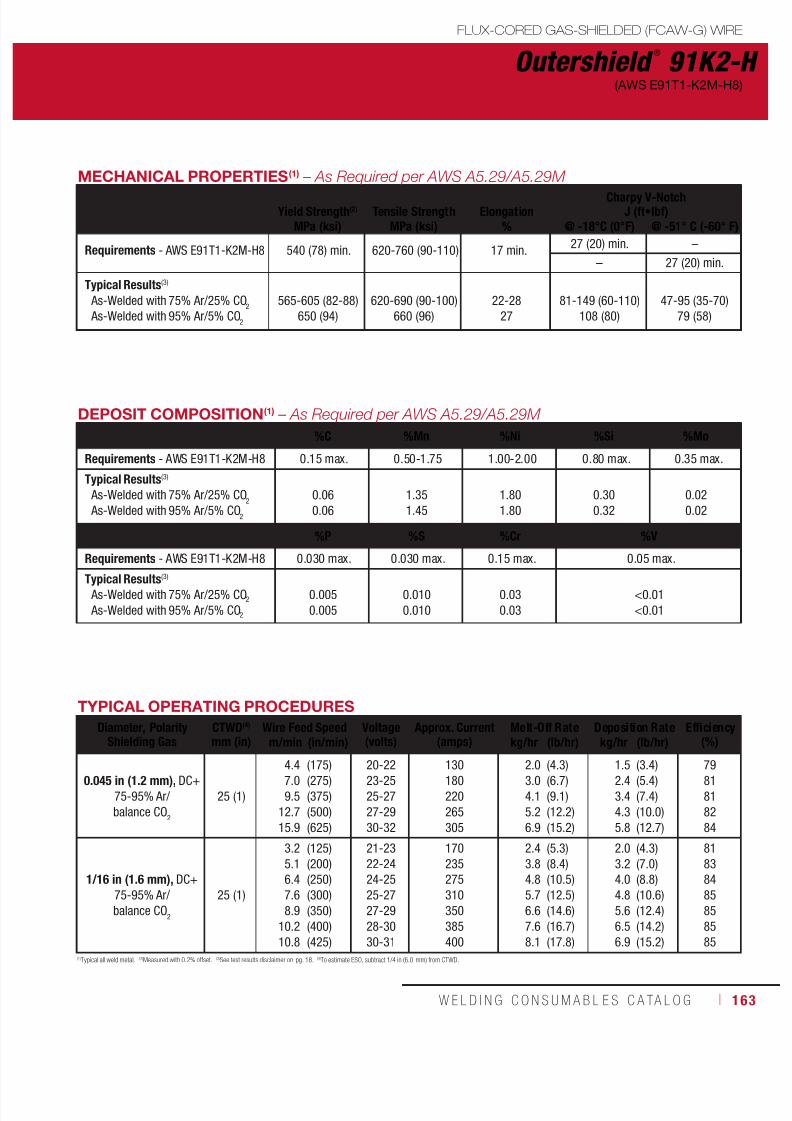
7/18/2019 c110 - Lincoln Electric Consumables 2014
http://slidepdf.com/reader/full/c110-lincoln-electric-consumables-2014 163/511W E L D I N G C O N S U M A B L E S C A TA L O G ı 163
MECHANICAL PROPERTIES(1) – As Required per AWS A5.29/A5.29M
Yield Strength(2) Tensile Strength ElongationCharpy V-Notch
J (ft•lbf)
MPa (ksi) MPa (ksi) % @ -18°C (0°F) @ -51° C (-60° F)
Requirements - AWS E91T1-K2M-H8 540 (78) min. 620-760 (90-110) 17 min.27 (20) min. –
– 27 (20) min.
Typical Results(3)
As-Welded with 75% Ar/25% CO2
As-Welded with 95% Ar/5% CO2
565-605 (82-88)650 (94)
620-690 (90-100)660 (96)
22-2827
81-149 (60-110)108 (80)
47-95 (35-70)79 (58)
Outershield ®
91K2-H
FLUX-CORED GAS-SHIELDED (FCAW-G) WIRE
(AWS E91T1-K2M-H8)
TYPICAL OPERATING PROCEDURES
Diameter, PolarityShielding Gas
CTWD(4)
mm (in)Wire Feed Speed Voltage
(volts)Approx. Current
(amps)Melt-Off Rate Deposition Rate Efficiency
(%)m/min (in/min) kg/hr (lb/hr) kg/hr (lb/hr)
0.045 in (1.2 mm), DC+75-95% Ar/balance CO
2
25 (1)
4.47.09.5
12.715.9
(175)(275)(375)(500)(625)
20-2223-2525-2727-2930-32
130180220265305
2.03.04.15.26.9
(4.3)(6.7)(9.1)(12.2)(15.2)
1.52.43.44.35.8
(3.4)(5.4)(7.4)(10.0)(12.7)
7981818284
1/16 in (1.6 mm), DC+75-95% Ar/balance CO
2
25 (1)
3.25.16.47.68.9
10.210.8
(125)(200)(250)(300)(350)(400)(425)
21-2322-2424-2525-2727-2928-3030-31
170235275310350385400
2.43.84.85.76.67.68.1
(5.3)(8.4)(10.5)(12.5)(14.6)(16.7)(17.8)
2.03.24.04.85.66.56.9
(4.3)(7.0)(8.8)(10.6)(12.4)(14.2)(15.2)
81838485858585
(1)Typical all weld metal. (2)Measured with 0.2% offset. (3)See test results disclaimer on pg. 18. (4)To estimate ESO, subtract 1/4 in (6.0 mm) from CTWD.
DEPOSIT COMPOSITION(1) – As Required per AWS A5.29/A5.29M
%C %Mn %Ni %Si %Mo
Requirements - AWS E91T1-K2M-H8 0.15 max. 0.50-1.75 1.00-2.00 0.80 max. 0.35 max.
Typical Results(3)
As-Welded with 75% Ar/25% CO2
As-Welded with 95% Ar/5% CO2
0.060.06
1.351.45
1.801.80
0.300.32
0.020.02
%P %S %Cr %V
Requirements - AWS E91T1-K2M-H8 0.030 max. 0.030 max. 0.15 max. 0.05 max.
Typical Results(3)
As-Welded with 75% Ar/25% CO2
As-Welded with 95% Ar/5% CO2
0.0050.005
0.0100.010
0.030.03
<0.01<0.01
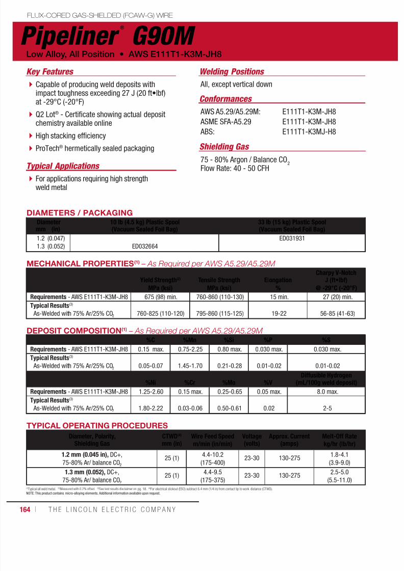
7/18/2019 c110 - Lincoln Electric Consumables 2014
http://slidepdf.com/reader/full/c110-lincoln-electric-consumables-2014 164/511164 ı T H E L I N C O L N E L E C T R I C C O M P A N Y
Pipeliner ®
G90M FLUX-CORED GAS-SHIELDED (FCAW-G) WIRE
Welding Positions
Typical Applications
All, except vertical down
For applications requiring high strengthweld metal
Capable of producing weld deposits withimpact toughness exceeding 27 J (20 ft•lbf)at -29°C (-20°F)
Q2 Lot® - Certificate showing actual depositchemistry available online
High stacking efficiency
ProTech® hermetically sealed packaging
Conformances
Shielding Gas
75 - 80% Argon / Balance CO2
Flow Rate: 40 - 50 CFH
Low Alloy, All Position • AWS E111T1-K3M-JH8
Key Features
AWS A5.29/A5.29M:
ASME SFA-A5.29
ABS:
E111T1-K3M-JH8
E111T1-K3M-JH8
E111T1-K3MJ-H8
DIAMETERS / PACKAGINGDiameter 10 lb (4.5 kg) Plastic Spool
(Vacuum Sealed Foil Bag)33 lb (15 kg) Plastic Spool(Vacuum Sealed Foil Bag)mm (in)
1.21.3
(0.047)(0.052) ED032664
ED031931
MECHANICAL PROPERTIES(1) – As Required per AWS A5.29/A5.29M
Yield Strength(2) Tensile Strength ElongationCharpy V-Notch
J (ft•lbf)
MPa (ksi) MPa (ksi) % @ -29°C (-20°F)
Requirements - AWS E111T1-K3M-JH8 675 (98) min. 760-860 (110-130) 15 min. 27 (20) min.
Typical Results(3)
As-Welded with 75% Ar/25% CO2 760-825 (110-120) 795-860 (115-125) 19-22 56-85 (41-63)
(1)Typical all weld metal. (2)Measured with 0.2% offset. (3)See test results disclaimer on pg. 18. (4)For electrical stickout (ESO) subtract 6.4 mm (1/4 in) from contact tip to work distance (CTWD).NOTE: This product contains micro-alloying elements. Additional information available upon request.
DEPOSIT COMPOSITION(1) – As Required per AWS A5.29/A5.29M %C %Mn %Si %P %S
Requirements - AWS E111T1-K3M-JH8 0.15 max. 0.75-2.25 0.80 max. 0.030 max. 0.030 max.
Typical Results(3)
As-Welded with 75% Ar/25% CO2 0.05-0.07 1.45-1.70 0.21-0.28 0.01-0.02 0.01-0.02
%Ni %Cr %Mo %VDiffusible Hydrogen
(mL/100g weld deposit)
Requirements - AWS E111T1-K3M-JH8 1.25-2.60 0.15 max. 0.25-0.65 0.05 max. 8.0 max.Typical Results(3)
As-Welded with 75% Ar/25% CO2 1.80-2.22 0.03-0.06 0.50-0.61 0.02 2-5
TYPICAL OPERATING PROCEDURES
Diameter, Polarity,Shielding Gas
CTWD(4)
mm (in)Wire Feed Speed Voltage
(volts)Approx. Current
(amps)Melt-Off Rate
m/min (in/min) kg/hr (lb/hr)
1.2 mm (0.045 in), DC+,75-80% Ar/ balance CO2
25 (1)4.4-10.2(175-400)
23-30 130-2751.8-4.1(3.9-9.0)
1.3 mm (0.052), DC+,75-80% Ar/ balance CO2
25 (1)4.4-9.5
(175-375)23-30 130-275
2.5-5.0(5.5-11.0)

7/18/2019 c110 - Lincoln Electric Consumables 2014
http://slidepdf.com/reader/full/c110-lincoln-electric-consumables-2014 165/511W E L D I N G C O N S U M A B L E S C A TA L O G ı 165
Cormet ®
1 FLUX-CORED GAS-SHIELDED (FCAW-G) WIRE
DIAMETERS / PACKAGINGDiameter 15 kg (33 lb)
Spoolmm (in)
1.2 (0.045) ED033354
Typical Applications Key Features
Shielding Gas
Welding Positions
Conformances
High metal recovery
Smooth arc performance in all positions
Designed for prolonged elevated temperatureservice up to 550°C (1022°F).
Refineries where corrosion resistance to sulphurbearing crude oil is at 250-450°C (482-842°F).
Petro-Chemical Power Plants Piping Turbine Casting Steam Chests Valve Bodies Boiler Superheaters
80% Argon / 20% CO2
100% CO2
All
AWS A5.29BS EN ISO 17634-B ASME IX
E81T1-B2C/M-H4T55T1-1C/M-1CMQW432 F-No 6, QW442 A-No 3
TYPICAL OPERATING PROCEDURESDiameterin (mm)
Amp-Volt Range
Typical
Stickoutmm (in)
1.2 (0.045) DC+160 - 260A
24 - 30V190A 25V
15 - 25(5/8 - 1)
DEPOSIT COMPOSITION(1) - As Required per AWS A5.29
%C %Mn %Si %S
Requirements AWS E81T1-B2C/M-H4 0.05 - 0.12 1.25 max. 0.80 max. 0.030 max.
Typical Results(3) 0.06 1.0 0.30 0.01
%P %Cr %Mo %Cu
Requirements AWS E81T1-B2C/M-H4 0.030 max. 1.00 - 1.50 0.40 - 0.65 0.30 max.
Typical Results(3) 0.01 1.3 0.55 0.05
MECHANICAL PROPERTIES(1) - As Required per AWS A5.29
Yield Strength(2)
MPa (ksi)
Tensile Strength
MPa (ksi)
Elongation %
Charpy V-NotchJ (ft•lbf)
HardnessHV10(4)
AW PWHT4.0 dia. 5.0 dia. @ 20°C (68°F)
Requirements AWS E81T1-B2C/M-H4 470 min. 550 min. 19 min. 17 min. – –
Typical PerformanceStress-Relieved
1-2 hr @ 690°C (1274°F) 550 650 24 22 >40 220
(1)Typical all weld metal. (2)Measured with 0.2% offset. (3)See test results disclaimer on p g. 18. (4)Industry specific data, not required by AWS.NOTE: Additional test data available upon request.
AWS E81T1-B2C/M-H4

7/18/2019 c110 - Lincoln Electric Consumables 2014
http://slidepdf.com/reader/full/c110-lincoln-electric-consumables-2014 166/511166 ı T H E L I N C O L N E L E C T R I C C O M P A N Y
Cormet ®
2 FLUX-CORED GAS-SHIELDED (FCAW-G) WIRE
AWS E91T1-B3C/M-H4
DIAMETERS / PACKAGINGDiameter 15 kg (33 lb)
Spoolmm (in)
1.2 (0.045) ED033365
Typical ApplicationsKey Features
Shielding gas
Welding Positions
Conformances
High metal recovery
Smooth arc performance in all positions
Designed for prolonged elevated temperatureservice up to 600°C (1112°F).
Refineries where corrosion resistance to sulphurbearing crude oil is at 250-450°C (482-842°F).
Petro-Chemical Power Plants Piping Turbine Casting Steam Chests Valve Bodies Boiler Superheaters
80% Argon / 20% CO2
100% CO2
All
AWS A5.29BS EN ISO 17634-B ASME IX
E91T1-B3C/M-H4T62T1-1C/M-2C1MQW432 F-No 6, QW442 A-No 4
TYPICAL OPERATING PROCEDURES
Diameterin (mm)
Amp-Volt Range
Typical
Stickoutin (mm)
1.2 (0.045) DC+160 - 260A
24 - 30V190A 25V
15 - 25(5/8 - 1)
DEPOSIT COMPOSITION(1) - As Required per AWS A5.29%C %Mn %Si %S
Requirements AWS E91T1-B3C/M-H4 0.05 - 0.12 1.25 max. 0.80 max. 0.030 max.
Typical Results(3) 0.06 1.0 0.30 0.01
%P %Cr %Mo %Cu
Requirements AWS E91T1-B3C/M-H4 0.030 max. 2.00 - 2.50 0.90 - 1.20 0.30 max.
Typical Results(3) 0.01 2.3 1.0 0.05
MECHANICAL PROPERTIES(1) - As Required per AWS A5.29
Yield Strength(2)
MPa (ksi)
Tensile StrengthMPa (ksi)
Elongation %
Charpy V-Notch
J (ft•lbf)
Hardness
HV10(4)
@ PWHT4.0 dia. 5.0 dia. @ 20°C (68°F)
Requirements AWS E91T1-B3C/M-H4 540 min. 620 min. 17 min. 15 min. – –
Typical Performance As-WeldedStress-Relieved
625 725 22 20 >70 235
(1)Typical all weld metal. (2)Measured with 0.2% offset. (3)See test results disclaimer on pg . 18. (4)Industry specific data, not required by AWS.NOTE: Additional test data available upon r equest.
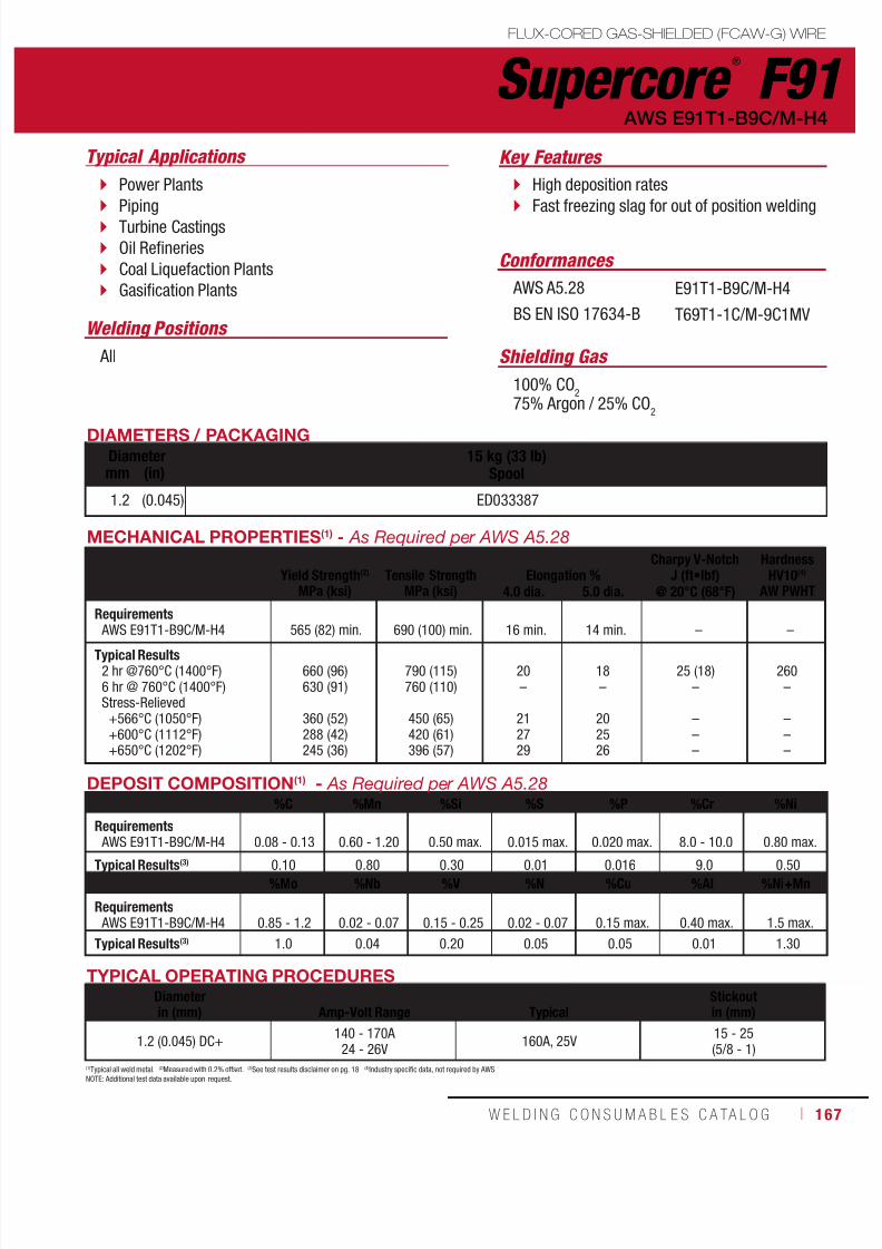
7/18/2019 c110 - Lincoln Electric Consumables 2014
http://slidepdf.com/reader/full/c110-lincoln-electric-consumables-2014 167/511W E L D I N G C O N S U M A B L E S C A TA L O G ı 167
Supercore ®
F91 FLUX-CORED GAS-SHIELDED (FCAW-G) WIRE
DIAMETERS / PACKAGING
Diameter 15 kg (33 lb)Spoolmm (in)
1.2 (0.045) ED033387
Typical Applications Key Features
Welding Positions
Shielding Gas
Conformances
High deposition rates
Fast freezing slag for out of position welding
Power Plants
Piping Turbine Castings Oil Refineries Coal Liquefaction Plants Gasification Plants
All
100% CO2
75% Argon / 25% CO2
AWS A5.28
BS EN ISO 17634-B
E91T1-B9C/M-H4
T69T1-1C/M-9C1MV
AWS E91T1-B9C/M-H4
TYPICAL OPERATING PROCEDURESDiameterin (mm)
Amp-Volt Range
Typical
Stickoutin (mm)
1.2 (0.045) DC+140 - 170A
24 - 26V160A, 25V
15 - 25(5/8 - 1)
DEPOSIT COMPOSITION(1) - As Required per AWS A5.28%C %Mn %Si %S %P %Cr %Ni
Requirements AWS E91T1-B9C/M-H4 0.08 - 0.13 0.60 - 1.20 0.50 max. 0.015 max. 0.020 max. 8.0 - 10.0 0.80 max.
Typical Results(3) 0.10 0.80 0.30 0.01 0.016 9.0 0.50
%Mo %Nb %V %N %Cu %Al %Ni+Mn
Requirements AWS E91T1-B9C/M-H4 0.85 - 1.2 0.02 - 0.07 0.15 - 0.25 0.02 - 0.07 0.15 max. 0.40 max. 1.5 max.
Typical Results(3) 1.0 0.04 0.20 0.05 0.05 0.01 1.30
MECHANICAL PROPERTIES(1) - As Required per AWS A5.28
Yield Strength(2)
MPa (ksi)
Tensile Strength
MPa (ksi)
Elongation %
Charpy V-NotchJ (ft•lbf)
HardnessHV10(4)
AW PWHT4.0 dia. 5.0 dia. @ 20°C (68°F)
Requirements AWS E91T1-B9C/M-H4 565 (82) min. 690 (100) min. 16 min. 14 min. – –
Typical Results2 hr @760°C (1400°F)6 hr @ 760°C (1400°F)Stress-Relieved
+566°C (1050°F)+600°C (1112°F)+650°C (1202°F)
660 (96)630 (91)
360 (52)288 (42)245 (36)
790 (115)760 (110)
450 (65)420 (61)396 (57)
20–
212729
18–
202526
25 (18)–
–––
260–
–––
(1)Typical all weld metal. (2)Measured with 0.2% offset. (3)See test results disclaimer on pg. 18 (4)Industry specific data, not required by AWS.NOTE: Additional test data available upon request.

7/18/2019 c110 - Lincoln Electric Consumables 2014
http://slidepdf.com/reader/full/c110-lincoln-electric-consumables-2014 168/511168 ı T H E L I N C O L N E L E C T R I C C O M P A N Y
Notes FLUX-CORED CONSUMABLES
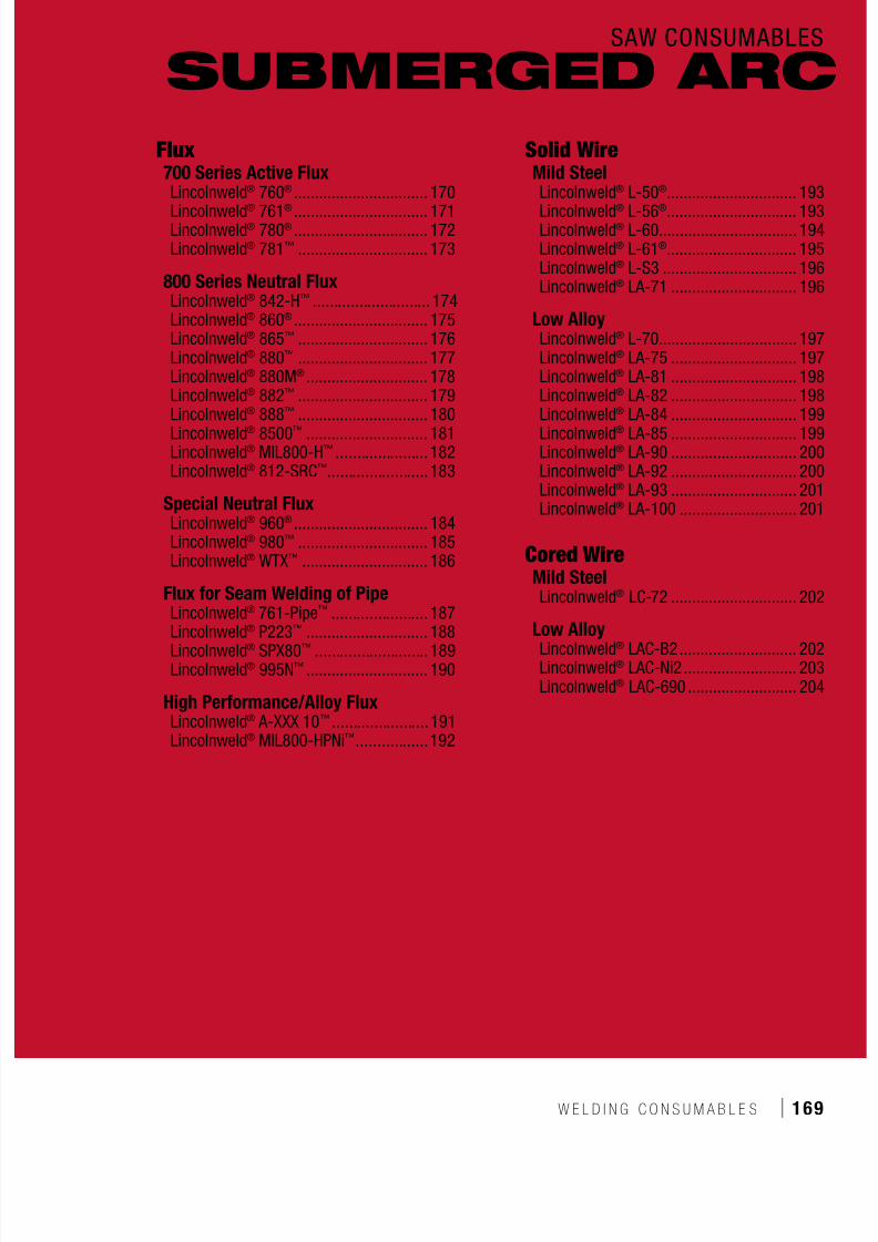
7/18/2019 c110 - Lincoln Electric Consumables 2014
http://slidepdf.com/reader/full/c110-lincoln-electric-consumables-2014 169/511W E L D I N G C O N S U M A B L E S ı 169
SAW CONSUMABLES
Flux700 Series Active FluxLincolnweld® 760® ................................ 170
Lincolnweld® 761® ................................ 171Lincolnweld® 780® ................................ 172Lincolnweld® 781™ ............................... 173
800 Series Neutral FluxLincolnweld® 842-H™ ............................ 174Lincolnweld® 860® ................................ 175Lincolnweld® 865™ ............................... 176Lincolnweld® 880™ ............................... 177Lincolnweld® 880M® ............................. 178Lincolnweld® 882™ ............................... 179Lincolnweld® 888™ ............................... 180Lincolnweld® 8500™ ............................. 181Lincolnweld® MIL800-H™ ...................... 182Lincolnweld® 812-SRC™ ........................183
Special Neutral FluxLincolnweld® 960® ................................ 184Lincolnweld® 980™ ............................... 185Lincolnweld® WTX™ .............................. 186
Flux for Seam Welding of PipeLincolnweld® 761-Pipe™ .......................187
Lincolnweld®
P223™
............................. 188Lincolnweld® SPX80™ ........................... 189Lincolnweld® 995N™ ............................. 190
High Performance/Alloy FluxLincolnweld® A-XXX 10™ .......................191Lincolnweld® MIL800-HPNi™ .................192
Solid WireMild SteelLincolnweld® L-50® ............................... 193
Lincolnweld® L-56® ............................... 193Lincolnweld® L-60................................. 194Lincolnweld® L-61® ............................... 195Lincolnweld® L-S3 ................................ 196Lincolnweld® LA-71 .............................. 196
Low AlloyLincolnweld® L-70................................. 197Lincolnweld® LA-75 .............................. 197Lincolnweld® LA-81 .............................. 198Lincolnweld® LA-82 .............................. 198Lincolnweld® LA-84 .............................. 199Lincolnweld® LA-85 .............................. 199Lincolnweld® LA-90 .............................. 200Lincolnweld® LA-92 .............................. 200Lincolnweld® LA-93 .............................. 201Lincolnweld® LA-100 ............................ 201
Cored WireMild SteelLincolnweld® LC-72 .............................. 202
Low AlloyLincolnweld® LAC-B2 ............................ 202Lincolnweld® LAC-Ni2 ........................... 203Lincolnweld® LAC-690 .......................... 204
SUBMERGED ARC
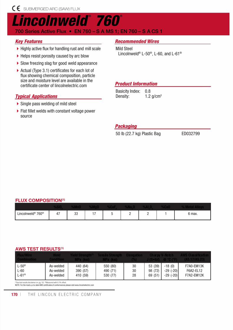
7/18/2019 c110 - Lincoln Electric Consumables 2014
http://slidepdf.com/reader/full/c110-lincoln-electric-consumables-2014 170/511170 ı T H E L I N C O L N E L E C T R I C C O M P A N Y
Lincolnweld ®
760 ®
SUBMERGED ARC (SAW) FLUX
Recommended Wires
Typical Applications
Mild SteelLincolnweld® L-50®, L-60, and L-61®
Single pass welding of mild steel
Flat fillet welds with constant voltage powersource
Highly active flux for handling rust and mill scale
Helps resist porosity caused by arc blow Slow freezing slag for good weld appearance
Actual (Type 3.1) certificates for each lot offlux showing chemical composition, particlesize and moisture level are available in thecertificate center of lincolnelectric.com Product Information
Basicity Index: 0.8Density: 1.2 g/cm3
700 Series Active Flux • EN 760 – S A MS 1; EN 760 – S A CS 1
Key Features
FLUX COMPOSITION(1)
%SiO2
%MnO %MgO %CaF2
%Na2O %Al
2O
3%CaO % Metal Alloys
Lincolnweld® 760® 47 33 17 5 2 2 1 6 max.
(1)See test results disclaimer on pg. 18. (2)Measured with 0.2% offset.NOTE: For the most u p-to-date AWS certificates of conformances please visit www.lincolnelectric.com
AWS TEST RESULTS(1)
Flux/WireCombination
WeldCondition
Yield Strength(2) Tensile Strength Elongation(%)
Charpy V-Notch AWS Classification(A5.17/A5.23)MPa (ksi) MPa (ksi) J (ft•lbf) @ °C (°F)
L-50®
L-60
L-61®
As-welded
As-welded
As-welded
440
390
410
(64)
(57)
(59)
550
490
530
(80)
(71)
(77)
30
30
28
53
98
69
(39)
(72)
(51)
-18
-29
-29
(0)
(-20)
(-20)
F7A0-EM13K
F6A2-EL12
F7A2-EM12K
Packaging
50 lb (22.7 kg) Plastic Bag ED032799

7/18/2019 c110 - Lincoln Electric Consumables 2014
http://slidepdf.com/reader/full/c110-lincoln-electric-consumables-2014 171/511W E L D I N G C O N S U M A B L E S C A TA L O G ı 171
SUBMERGED ARC (SAW) FLUX
(1)See test results disclaimer on pg. 18. (2)Measured with 0.2% offset.NOTE: For the most up-to-date AWS certificates of conformances please visit www.lincolnelectric.com
Lincolnweld ®
761®
Recommended Wires
Typical Applications
Mild SteelLincolnweld® L-50®, L-60, and L-61®
Low Alloy SteelLincolnweld® L-70
Single pass welding of mild steel
Large fillets with constant current power sources
Manganese alloying and carbon reducingflux designed to provide superior crackresistance
Slow freezing slag for a wide, flat weld
Excellent resistance to cracking in singlepass applications
Actual (Type 3.1) certificates for each lot offlux showing chemical composition, particlesize and moisture level are available in thecertificate center of lincolnelectric.com
Product Information
Basicity Index: 0.8Density: 1.2 g/cm3
EN 760 – S A MS 1; EN 760 – S A CS 1 • 700 Series Active Flux
Key Features
FLUX COMPOSITION(1)
%SiO2
%MnO %MgO %CaF2
%Na2O %Al
2O
3%TiO
2%FeO % Metal Alloys
Lincolnweld® 761® 45 19 22 5 2 2 2 1 6 max.
AWS TEST RESULTS(1)
Flux/WireCombination
WeldCondition
Yield Strength(2) Tensile Strength Elongation(%)
Charpy V-Notch AWS Classification(A5.17/A5.23)MPa (ksi) MPa (ksi) J (ft•lbf) @ °C (°F)
L-50®
L-60
L-61®
L-70
As-welded
As-welded
As-welded
As-welded
480
440
480
550
(69)
(64)
(70)
(80)
590
530
590
640
(85)
(75)
(85)
(93)
29
29
28
24
45
64
54
58
(33)
(47)
(40)
(43)
-29
-29
-29
-18
(-20)
(-20)
(-20)
(0)
F7A2-EM13K-H8
F7A2-EL12
F7A2-EM12K-H8
F9A0-EA1-G
Packaging
50 lb (22.7 kg) Plastic Bag ED032765

7/18/2019 c110 - Lincoln Electric Consumables 2014
http://slidepdf.com/reader/full/c110-lincoln-electric-consumables-2014 172/511172 ı T H E L I N C O L N E L E C T R I C C O M P A N Y
Lincolnweld ®
780 ®
SUBMERGED ARC (SAW) FLUX
Recommended Wires
Typical Applications
Mild Steel Lincolnweld® L-50®, L-60 and L-61®
Single pass welding of mild steel
Roundabouts with minimal spillage
Horizontal position welding
Industry standard for submerged arc weldingapplications
Fast freezing slag for easy removal andminimized spilling on circumferential welds
When paired with Lincolnweld® L-61® it isrecommended for up to three pass weldingapplications
Excellent bead shape and slag removal
Good resistance to moisture contaminationfor reduced porosity
Actual (Type 3.1) certificates for each lot offlux showing chemical composition, particlesize and moisture level are available in thecertificate center of lincolnelectric.com
Product Information
Basicity Index: 0.7Density: 1.4 g/cm3
700 Series Active Flux • EN 760 – S A AB 1; EN 760 – S A AR 1
Key Features
FLUX COMPOSITION(1)
%SiO2
%MnO %MgO %CaF2
%Na2O %Al
2O
3%CaO %TiO
2% Metal Alloys
Lincolnweld® 780® 9 16 2 11 2 45 1 9 6 max.
AWS TEST RESULTS(1)
Flux/WireCombination
WeldCondition
Yield Strength(2) Tensile Strength Elongation(%)
Charpy V-Notch AWS Classification(A5.17/A5.23)MPa (ksi) MPa (ksi) J (ft•lbf) @ °C (°F)
L-50®
L-60
L-61®
As-welded
As-welded
As-welded
520
440
530
(75)
(64)
(77)
600
520
600
(87)
(76)
(87)
27
30
27
65
88
46
(48)
(65)
(34)
-18
-18
-29
(0)
(0)
(-20)
F7A0-EM13K
F7A0-EL12-H8
F7A2-EM12K-H8
(1)See test results disclaimer on pg. 18. (2)Measured with 0.2% offset.NOTE: For the most u p-to-date AWS certificates of conformances please visit www.lincolnelectric.com
Packaging
50 lb (22.7 kg) Bag550 lb (249.5 kg) Steel Drum3000 lb (1361 kg) Bulk Bag
ED019586ED032007ED033188
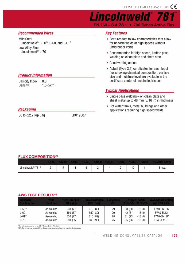
7/18/2019 c110 - Lincoln Electric Consumables 2014
http://slidepdf.com/reader/full/c110-lincoln-electric-consumables-2014 173/511W E L D I N G C O N S U M A B L E S C A TA L O G ı 173
Lincolnweld ®
781™
SUBMERGED ARC (SAW) FLUX
Recommended Wires
Typical Applications
Mild SteelLincolnweld® L-50®, L-60, and L-61®
Low Alloy SteelLincolnweld® L-70
Single pass welding – on clean plate andsheet metal up to 48 mm (3/16 in) in thickness
Hot water tanks, metal buildings and otherapplications requiring high speed welds
Features fast follow characteristics that allowfor uniform welds at high speeds withoutundercut or voids
Recommended for high speed, limited passwelding on clean plate and sheet steel
Good wetting action
Actual (Type 3.1) certificates for each lot offlux showing chemical composition, particlesize and moisture level are available in thecertificate center of lincolnelectric.com
Product Information
Basicity Index: 0.8Density: 1.5 g/cm3
EN 760 – S A ZS 1 • 700 Series Active Flux
Key Features
FLUX COMPOSITION(1)
%SiO2
%MnO %MgO %CaF2
%Na2O %Al
2O
3%ZrO
2%TiO
2%CaO % Metal Alloys
Lincolnweld® 781® 21 17 14 5 2 4 21 12 1 3 max.
AWS TEST RESULTS(1)
Flux/WireCombination
WeldCondition
Yield Strength(2) Tensile Strength Elongation(%)
Charpy V-Notch AWS Classification(A5.17/A5.23)MPa (ksi) MPa (ksi) J (ft•lbf) @ °C (°F)
L-50®
L-60
L-61®
L-70
As-welded
As-welded
As-welded
As-welded
530
460
530
590
(77)
(67)
(77)
(85)
610
550
610
660
(89)
(80)
(89)
(96)
29
29
28
25
38
42
31
35
(28)
(31)
(23)
(26)
-18
-18
-18
-18
(0)
(0)
(0)
(0)
F7A0-EM13K
F7A0-EL12
F7A0-EM12K
F9A0-EA1-G
(1)See test results disclaimer on pg. 18. (2)Measured with 0.2% offset.NOTE: For the most up-to-date AWS certificates of conformances please visit www.lincolnelectric.com
Packaging
50 lb (22.7 kg) Bag ED019587
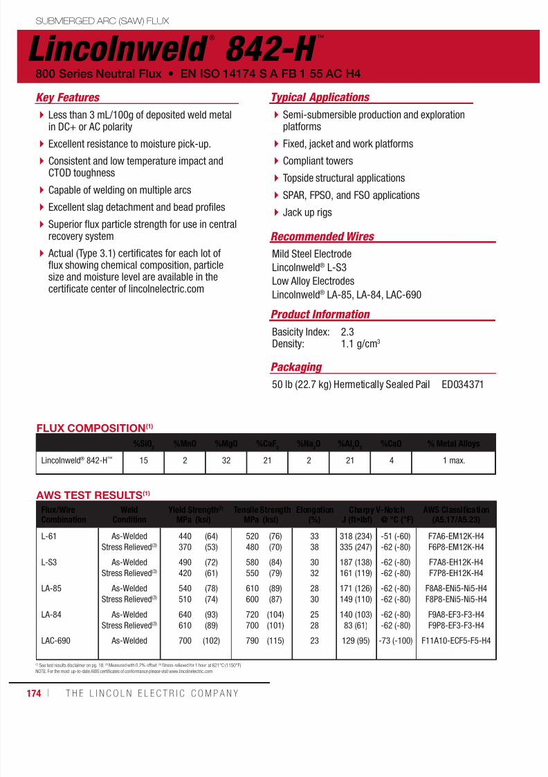
7/18/2019 c110 - Lincoln Electric Consumables 2014
http://slidepdf.com/reader/full/c110-lincoln-electric-consumables-2014 174/511174 ı T H E L I N C O L N E L E C T R I C C O M P A N Y
(1) See test results disclaimer on pg. 18. (2) Measured with 0.2% offset. (3) Stress-relieved for 1 hour at 621°C (1150°F)NOTE: For the most up-to-date AWS certificates of conformance please visit www.lincolnelectric.com
Lincolnweld ®
842-H ™
Recommended Wires
Typical Applications
Mild Steel Electrode
Lincolnweld® L-S3Low Alloy Electrodes
Lincolnweld® LA-85, LA-84, LAC-690
Semi-submersible production and explorationplatforms
Fixed, jacket and work platforms
Compliant towers
Topside structural applications
SPAR, FPSO, and FSO applications
Jack up rigs
Less than 3 mL/100g of deposited weld metalin DC+ or AC polarity
Excellent resistance to moisture pick-up.
Consistent and low temperature impact andCTOD toughness
Capable of welding on multiple arcs
Excellent slag detachment and bead profiles
Superior flux particle strength for use in centralrecovery system
Actual (Type 3.1) certificates for each lot of
flux showing chemical composition, particlesize and moisture level are available in thecertificate center of lincolnelectric.com
Product Information
Basicity Index: 2.3Density: 1.1 g/cm3
800 Series Neutral Flux • EN ISO 14174 S A FB 1 55 AC H4
Key Features
Packaging
50 lb (22.7 kg) Hermetically Sealed Pail ED034371
AWS TEST RESULTS(1)
Flux/WireCombination
WeldCondition
Yield Strength(2) Tensile Strength Elongation(%)
Charpy V-Notch AWS Classification(A5.17/A5.23)MPa (ksi) MPa (ksi) J (ft•lbf) @ °C (°F)
L-61
L-S3
LA-85
LA-84
LAC-690
As-Welded
Stress Relieved(3)
As-Welded
Stress Relieved(3)
As-Welded
Stress Relieved(3)
As-Welded
Stress Relieved(3)
As-Welded
440
370
490
420
540
510
640
610
700
(64)
(53)
(72)
(61)
(78)
(74)
(93)
(89)
(102)
520
480
580
550
610
600
720
700
790
(76)
(70)
(84)
(79)
(89)
(87)
(104)
(101)
(115)
33
38
30
32
28
30
25
28
23
318 (234)
335 (247)
187 (138)
161 (119)
171 (126)
149 (110)
140 (103)
83 (61)
129 (95)
-51 (-60)
-62 (-80)
-62 (-80)
-62 (-80)
-62 (-80)
-62 (-80)
-62 (-80)
-62 (-80)
-73 (-100)
F7A6-EM12K-H4
F6P8-EM12K-H4
F7A8-EH12K-H4
F7P8-EH12K-H4
F8A8-ENi5-Ni5-H4
F8P8-ENi5-Ni5-H4
F9A8-EF3-F3-H4
F9P8-EF3-F3-H4
F11A10-ECF5-F5-H4
FLUX COMPOSITION(1)
%SiO2
%MnO %MgO %CaF2
%Na2O %Al
2O
3%CaO % Metal Alloys
Lincolnweld® 842-H™ 15 2 32 21 2 21 4 1 max.
SUBMERGED ARC (SAW) FLUX
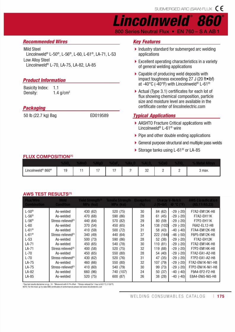
7/18/2019 c110 - Lincoln Electric Consumables 2014
http://slidepdf.com/reader/full/c110-lincoln-electric-consumables-2014 175/511W E L D I N G C O N S U M A B L E S C A TA L O G ı 175
Lincolnweld ®
860 ®
Recommended Wires
Typical Applications
Mild SteelLincolnweld® L-50®, L-56®, L-60, L-61®, LA-71, L-S3
Low Alloy SteelLincolnweld® L-70, LA-75, LA-82, LA-85
AASHTO Fracture Critical applications withLincolnweld® L-61® wire
Pipe and other double ending applications
General purpose structural and multiple pass welds
Storage tanks using L-61® or LA-85
Industry standard for submerged arc weldingapplications
Excellent operating characteristics in a varietyof general welding applications
Capable of producing weld deposits withimpact toughness exceeding 27 J (20 ft•lbf)at -40°C (-40°F) with Lincolnweld® L-61®
Actual (Type 3.1) certificates for each lot offlux showing chemical composition, particlesize and moisture level are available in thecertificate center of lincolnelectric.com
Product Information
Basicity Index: 1.1Density: 1.4 g/cm3
800 Series Neutral Flux • EN 760 – S A AB 1
Key Features
Packaging
50 lb (22.7 kg) Bag ED019589
(1)See test results disclaimer on pg . 18. (2)Measured with 0.2% offset. (3)Stress-relieved for 1 hour at 621°C (1150°F).NOTE: For the most up-to-date AWS certificates of conformances please visit www.lincolnelectric.com
AWS TEST RESULTS(1)
Flux/WireCombination
WeldCondition
Yield Strength(2) Tensile Strength Elongation(%)
Charpy V-Notch AWS Classification(A5.17/A5.23)MPa (ksi) MPa (ksi) J (ft•lbf) @ °C (°F)
L-50®
L-56®
L-56®
L-60L-61®
L-61®
L-S3
LA-71
LA-71
L-70
L-70
LA-75
LA-75
LA-82
LA-85
As-welded
As-welded
Stress-relieved(3)
As-welded As-welded
Stress-relieved(3)
As-welded
As-welded
Stress relieved(3)
As-welded
Stress-relieved(3)
As-welded
Stress-relieved(3)
As-welded
As-welded
430
470
440
370410
340
500
450
400
450
430
460
410
660
520
(62)
(68)
(64)
(54)(59)
(49)
(73)
(65)
(58)
(65)
(62)
(66)
(60)
(96)
(75)
520
590
570
450500
440
590
540
520
550
520
550
540
740
600
(75)
(86)
(82)
(65)(72)
(64)
(86)
(78)
(75)
(80)
(76)
(80)
(79)
(107)
(87)
30
28
29
3431
37
28
30
32
28
31
32
30
24
26
84
61
80
13858
222
52
110
119
54
47
107
99
50
38
(62)
(45)
(59)
(102)(43)
(164)
(38)
(81)
(88)
(40)
(35)
(79)
(73)
(37)
(28)
-29
-29
-29
-29-40
-46
-29
-29
-29
-29
-29
-29
-29
-40
-40
(-20)
(-20)
(-20)
(-20)(-40)
(-50)
(-20)
(-20)
(-20)
(-20)
(-20)
(-20)
(-20)
(-40)
(-40)
F7A2-EM13K-H8
F7A2-EH11K
F7P2-EH11K
F6A2-EL12-H8F7A4-EM12K-H8
F6P5-EM12K-H8
F7A2-EH12K
F7A2-EM14K-H8
F7P2-EM14K-H8
F7A2-EA1-A2-H8
F7P2-EA1-A2-H8
F7A2-ENi1K-Ni1-H8
F7P2-ENi1K-Ni1-H8
F9A4-EF2-F2-H8
E8A4-ENi5-Ni5-H8
FLUX COMPOSITION(1)
%SiO2
%MnO %MgO %CaF2
%Na2O %Al
2O
3%CaO %TiO
2% Metal Alloys
Lincolnweld® 860® 19 11 17 12 2 32 2 2 3 max.
SUBMERGED ARC (SAW) FLUX

7/18/2019 c110 - Lincoln Electric Consumables 2014
http://slidepdf.com/reader/full/c110-lincoln-electric-consumables-2014 176/511176 ı T H E L I N C O L N E L E C T R I C C O M P A N Y
Lincolnweld ®
865 ™
Recommended Wires
Typical Applications
Mild SteelLincolnweld® L-50®, L-61®, LA-71
Low Alloy SteelLincolnweld® LA-75
Butt joints and flat and horizontal fillets
Pair with Lincolnweld® L-61® on A516 steels
General purpose flux designed to weld butt joints and flat and horizontal fillets
When used with Lincolnweld® L-50® or L-61®,it is capable of producing 480 MPa (70 ksi)tensile strength after stress relief
Small loss of strength when used in thestress-relieved condition
Actual (Type 3.1) certificates for each lot offlux showing chemical composition, particlesize and moisture level are available in thecertificate center of lincolnelectric.com
Product Information
Basicity Index: 1.0Density: 1.3 g/cm3
EN 760 – S A AB 1; EN 760 – S A AR 1 • 800 Series Neutral Flux
Key Features
FLUX COMPOSITION(1)
%SiO2
%MnO %MgO %CaF2
%Na2O %Al
2O
3%TiO
2% Metal Alloys
Lincolnweld® 865™ 11 1 14 19 2 37 12 3 max.
AWS TEST RESULTS(1)
Flux/WireCombination
WeldCondition
Yield Strength(2) Tensile trength Elongation(%)
Charpy V-Notch AWS Classification(A5.17/A5.23)MPa (ksi) MPa (ksi) J (ft•lbf) @ °C (°F)
L-50®
L-50®
L-61®
L-61®
LA-71
LA-75
LA-75
As-welded
Stress-relieved(3)
As-welded
Stress-relieved(3)
As-welded
As-welded
Stress-relieved(3)
500
440
480
450
540
520
500
(72)
(64)
(70)
(65)
(78)
(76)
(73)
580
550
570
550
630
600
610
(84)
(80)
(83)
(80)
(91)
(87)
(88)
27
30
22
30
26
23
27
53
28
85
117
73
77
79
(39)
(21)
(63)
(86)
(54)
(57)
(58)
-29
-46
-29
-29
-29
-29
-29
(-20)
(-50)
(-20)
(-20)
(-20)
(-20)
(-20)
F7A2-EM13K-H8
F7P5-EM13K-H8
F7A2-EM12K-H8
F7P2-EM12K-H8
F7A2-EM14K-H8
F8A2-ENi1K-G-H8
F8P2-ENi1K-G-H8
(1)See test results disclaimer on pg. 18. (2)Measured with 0.2% offset. (3)Stress-relieved for 1 hour at 621°C (1150°F).NOTE: For the most u p-to-date AWS certificates of conformances please visit www.lincolnelectric.com
Packaging
50 lb (22.7 kg) Bag EDS27857
SUBMERGED ARC (SAW) FLUX
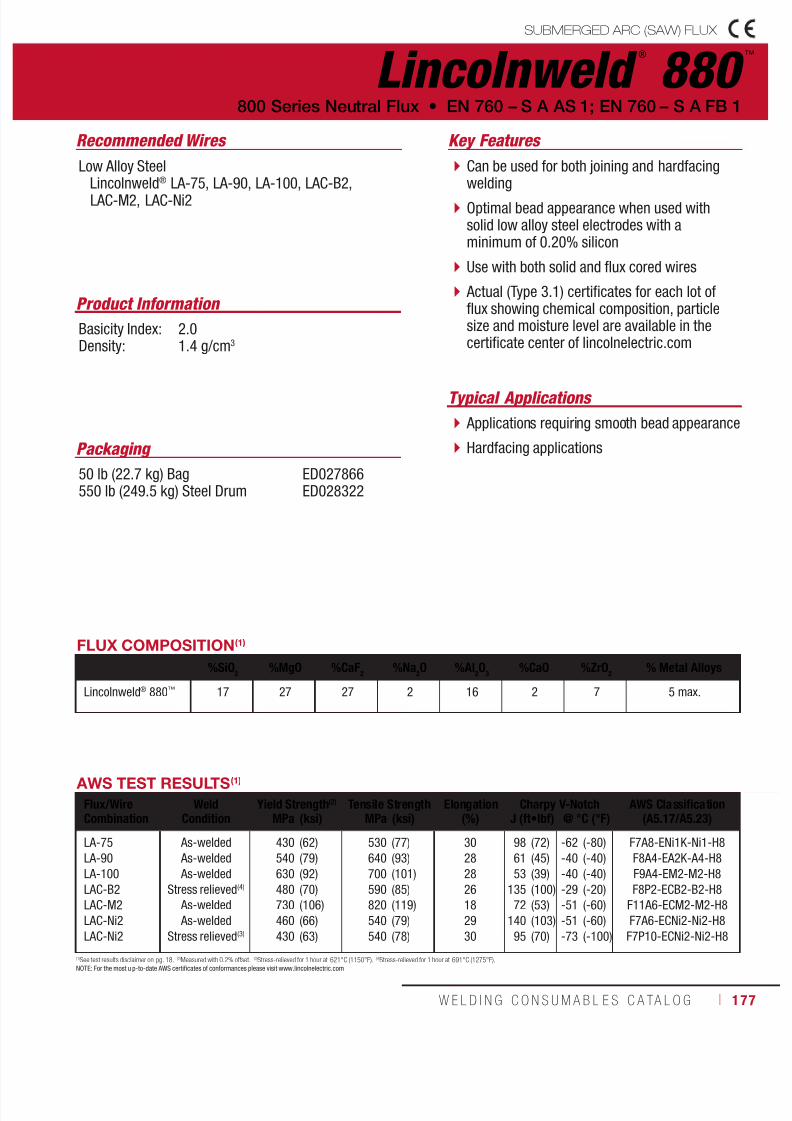
7/18/2019 c110 - Lincoln Electric Consumables 2014
http://slidepdf.com/reader/full/c110-lincoln-electric-consumables-2014 177/511W E L D I N G C O N S U M A B L E S C A TA L O G ı 177
SUBMERGED ARC (SAW) FLUX
Lincolnweld ®
880 ™
Recommended Wires
Typical Applications
Low Alloy Steel Lincolnweld® LA-75, LA-90, LA-100, LAC-B2,
LAC-M2, LAC-Ni2
Applications requiring smooth bead appearance
Hardfacing applications
Can be used for both joining and hardfacingwelding
Optimal bead appearance when used withsolid low alloy steel electrodes with aminimum of 0.20% silicon
Use with both solid and flux cored wires
Actual (Type 3.1) certificates for each lot offlux showing chemical composition, particlesize and moisture level are available in thecertificate center of lincolnelectric.com
Product Information
Basicity Index: 2.0Density: 1.4 g/cm3
800 Series Neutral Flux • EN 760 – S A AS 1; EN 760 – S A FB 1
Key Features
Packaging
50 lb (22.7 kg) Bag550 lb (249.5 kg) Steel Drum
ED027866ED028322
FLUX COMPOSITION(1)
%SiO2
%MgO %CaF2
%Na2O %Al
2O
3%CaO %ZrO
2% Metal Alloys
Lincolnweld® 880™ 17 27 27 2 16 2 7 5 max.
AWS TEST RESULTS(1)
Flux/WireCombination
WeldCondition
Yield Strength(2) Tensile Strength Elongation(%)
Charpy V-Notch AWS Classification(A5.17/A5.23)MPa (ksi) MPa (ksi) J (ft•lbf) @ °C (°F)
LA-75
LA-90
LA-100
LAC-B2
LAC-M2
LAC-Ni2
LAC-Ni2
As-welded
As-welded
As-welded
Stress relieved(4)
As-welded
As-welded
Stress relieved(3)
430
540
630
480
730
460
430
(62)
(79)
(92)
(70)
(106)
(66)
(63)
530
640
700
590
820
540
540
(77)
(93)
(101)
(85)
(119)
(79)
(78)
30
28
28
26
18
29
30
98
61
53
135
72
140
95
(72)
(45)
(39)
(100)
(53)
(103)
(70)
-62
-40
-40
-29
-51
-51
-73
(-80)
(-40)
(-40)
(-20)
(-60)
(-60)
(-100)
F7A8-ENi1K-Ni1-H8
F8A4-EA2K-A4-H8
F9A4-EM2-M2-H8
F8P2-ECB2-B2-H8
F11A6-ECM2-M2-H8
F7A6-ECNi2-Ni2-H8
F7P10-ECNi2-Ni2-H8
(1)See test results disclaimer on pg. 18. (2)Measured with 0.2% offset. (3)Stress-relieved for 1 hour at 621°C (1150°F). (4)Stress-relieved for 1 hour at 691°C (1275°F).NOTE: For the most u p-to-date AWS certificates of conformances please visit www.lincolnelectric.com

7/18/2019 c110 - Lincoln Electric Consumables 2014
http://slidepdf.com/reader/full/c110-lincoln-electric-consumables-2014 178/511178 ı T H E L I N C O L N E L E C T R I C C O M P A N Y
Lincolnweld ®
880M ®
Recommended Wires
Typical Applications
Mild SteelLincolnweld® L-50®, L-56®, LA-71, L-S3
Low Alloy SteelLincolnweld® LA-75, LA-85, LA-90, LA-92, LA-93,LA-100, LAC-B2, LAC-M2, LAC-Ni2
Tandem arc applications for offshorefabrication
Jobs requiring 480 MPa (70 ksi) tensile strength afterstress relief when used with L-56®, L-S3, or LA-71
A basic flux which features industry provenresults in multiple pass applications
Recommended for welding with solid mild steeland low alloy electrodes, as well as Lincoln’sLAC series of low alloy flux-cored electrodes
Good deep groove slag removal
Excellent choice for single arc AC submergedarc welding
Actual (Type 3.1) certificates for each lot offlux showing chemical composition, particlesize and moisture level are available in the
certificate center of lincolnelectric.com
Product Information
Basicity Index: 3.3Density: 1.2 g/cm3
EN 760 – S A FB 1 • 800 Series Neutral Flux
Key Features
Packaging
50 lb (22.7 kg) Plastic Bag ED031853
FLUX COMPOSITION(1)
%SiO2
%MnO %MgO %CaF2
%Na2O %Al
2O
3%CaO %K
2O % Metal Alloys
Lincolnweld® 880M® 12 1 29 29 1 18 8 1 1 max.
AWS TEST RESULTS(1)
Flux/WireCombination
WeldCondition
Yield Strength(2) Tensile Strength Elongation(%)
Charpy V-Notch AWS Classification(A5.17/A5.23)MPa (ksi) MPa (ksi) J (ft•lbf) @ °C (°F)
L-50®
L-56®
L-56®
L-S3
LA-71
LA-71
LA-75LA-85
LA-85
LA-90
LA-90
LA-92
LA-93
LA-100
LAC-B2
LAC-M2
LAC-Ni2
LAC-Ni2
As-welded
As-welded
Stress-relieved(3)
As-welded
As-welded
Stress-relieved(3)
As-welded As-welded
Stress-relieved(3)
As-welded
Stress-relieved(3)
Stress-relieved(4)
Stress-relieved(4)
As-welded
Stress-relieved(4)
As-welded
As-welded
Stress-relieved(3)
410
480
400
400
480
430
440520
490
580
520
460
510
680
500
760
510
480
(59)
(69)
(58)
(58)
(70)
(63)
(64)(76)
(71)
(84)
(75)
(66)
(74)
(98)
(72)
(110)
(73)
(69)
510
580
540
510
570
550
550610
590
680
630
570
610
730
600
820
600
570
(74)
(85)
(78)
(74)
(82)
(80)
(80)(88)
(85)
(99)
(91)
(82)
(88)
(106)
(87)
(119)
(87)
(83)
32
31
32
32
29
31
3124
27
26
28
28
26
25
25
23
22
28
263
121
158
264
143
164
16757
145
68
145
178
214
129
144
83
77
103
(194)
(89)
(116)
(195)
(105)
(121)
(123)(42)
(107)
(50)
(107)
(131)
(158)
(95)
(106)
(61)
(57)
(76)
-62
-51
-51
-51
-62
-62
-62-51
-62
-51
-62
-29
-18
-51
-29
-51
-73
-73
(-80)
(-60)
(-60)
(-60)
(-80)
(-80)
(-80)(-60)
(-80)
(-60)
(-80)
(-20)
(0)
(-60)
(-20)
(-60)
(-100)
(-100)
F7A8-EM13K-H8
F7A6-EH11K-H8
F7P6-EH11K-H8
F7A6-EH12K-H8
F7A8-EM14K-H8
F7P8-EM14K-H8
F7A8-ENi1K-Ni1-H8F7A6-ENi5-Ni5-H8
F7P8-ENi5-Ni5-H8
F9A6-EA3K-A3-H8
F8P8-EA3K-A3-H8
F7P2-EB2R-B2-H8
F7P0-EB3R-B3-H8
F9A6-EM2-M2-H8
F8P2-ECB2-B2-H8
F11A6-ECM2-M2-H8
F7A10-ECNi2-Ni2-H8
F7P10-ECNi2-Ni2-H8
(1)See test results disclaimer on pg. 18. (2)Measured with 0.2% offset. (3)Stress-relieved for 1 hour at 621°C (1150°F). (4)Stress-relieved for 1 hour at 691°C (1275°F).NOTE: For the most up-to-date AWS certificates of conformances please visit www.lincolnelectric.com
SUBMERGED ARC (SAW) FLUX

7/18/2019 c110 - Lincoln Electric Consumables 2014
http://slidepdf.com/reader/full/c110-lincoln-electric-consumables-2014 179/511W E L D I N G C O N S U M A B L E S C A TA L O G ı 179
SUBMERGED ARC (SAW) FLUX
Lincolnweld ®
882 ™
Recommended Wires
Typical Applications
Mild SteelLincolnweld® L-50®, L-56®, L-60, L-61®, LA-71, L-S3
Low Alloy SteelLincolnweld® L-70, LA-75, LA-82, LA-85, LA-92,LA-93, LAC-Ni2
Single wire or tandem welding
Used for welding of stainless, mild and lowalloy steel
Excellent for multiple pass fillet welds
Designed for a variety of welding applicationsand is known for providing consistentmechanical properties
Recommended for stainless steel welding andcan be paired with both mild and low alloysteel electrodes
Smooth bead appearance
Actual (Type 3.1) certificates for each lot offlux showing chemical composition, particlesize and moisture level are available in thecertificate center of lincolnelectric.com
Product Information
Basicity Index: 1.6Density: 1.2 g/cm3
800 Series Neutral Flux • EN 760 – S A AS 1; EN 760 – S A AS 2
Key Features
Packaging 50 lb (22.7 kg) Bag ED027859
FLUX COMPOSITION(1)
%SiO2
%MnO %MgO %CaF2
%Na2O %Al
2O
3%CaO %ZrO
2% Metal Alloys
Lincolnweld® 882™ 16 1 22 24 2 24 1 7 3 max.
AWS TEST RESULTS(1)
Flux/WireCombination
WeldCondition
Yield Strength(2) Tensile Strength Elongation(%)
Charpy V-Notch AWS Classification(A5.17/A5.23)MPa (ksi) MPa (ksi) J (ft•lbf) @ °C (°F)
L-50®
L-56®
L-56®
L-60
L-61®
L-S3LA-71
LA-71
L-70
LA-75
LA-82
LA-85
LA-85
LA-92
LA-93
LAC-Ni2
LAC-Ni2
As-welded
As-welded
Stress-relieved(3)
As-welded
As-welded
As-welded As-welded
Stress-relieved(3)
Stress-relieved(3)
As-welded
As-welded
As-welded
Stress-relieved(3)
Stress-relieved(4)
Stress-relieved(4)
As-welded
Stress-relieved(3)
420
500
420
370
400
410480
430
450
430
660
510
500
520
610
570
500
(61)
(73)
(61)
(54)
(58)
(60)(69)
(62)
(65)
(62)
(95)
(74)
(73)
(75)
(88)
(83)
(73)
520
600
560
460
500
520570
550
550
540
740
610
590
610
700
660
600
(76)
(87)
(81)
(67)
(72)
(76)(82)
(80)
(80)
(79)
(108)
(88)
(86)
(89)
(101)
(95)
(87)
29
28
30
32
31
2831
32
30
32
26
25
26
27
23
20
25
130
92
47
207
190
13061
70
76
133
56
88
102
83
214
72
100
(96)
(68)
(35)
(153)
(140)
(96)(45)
(52)
(56)
(98)
(41)
(65)
(75)
(61)
(158)
(53)
(74)
-51
-40
-46
-51
-51
-51-51
-51
-40
-40
-51
-40
-40
-29
-18
-40
-40
(-60)
(-40)
(-50)
(-60)
(-60)
(-60)(-60)
(-60)
(-40)
(-40)
(-60)
(-40)
(-40)
(-20)
(0)
(-40)
(-40)
F7A6-EM13K-H8
F7A4-EH11K-H8
F7P5-EH11K-H8
F6A6-EL12-H8
F7A6-EM12K-H8
F7A6-EH12K-H8F7A6-EM14K-H8
F7P6-EM14K-H8
F7P4-EA1-A2-H8
F7A4-ENi1K-Ni1-H8
F10A6-EF2-F2-H8
F7A4-ENi5-Ni5-H8
F7P4-ENi5-Ni5-H8
F7P2-EB2R-B2-H8
F9P0-EB3R-B3-H8
F8A4-ECNi2-Ni2-H8
F7P4-ECNi2-Ni2-H8
(1)See test results disclaimer on pg. 18. (2)Measured with 0.2% offset. (3)Stress-relieved for 1 hour at 621°C (1150°F). (4)Stress-relieved for 1 hour at 691°C (1275°F).NOTE: For the most up-to-date AWS certificates of conformances please visit www.lincolnelectric.com
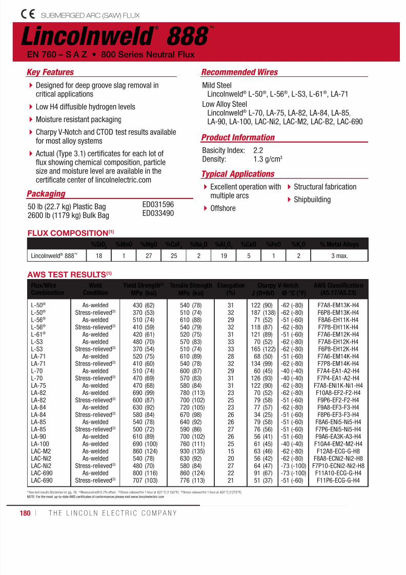
7/18/2019 c110 - Lincoln Electric Consumables 2014
http://slidepdf.com/reader/full/c110-lincoln-electric-consumables-2014 180/511180 ı T H E L I N C O L N E L E C T R I C C O M P A N Y
Lincolnweld ®
888 ™
Designed for deep groove slag removal incritical applications
Low H4 diffusible hydrogen levels
Moisture resistant packaging
Charpy V-Notch and CTOD test results availablefor most alloy systems
Actual (Type 3.1) certificates for each lot offlux showing chemical composition, particlesize and moisture level are available in thecertificate center of lincolnelectric.com
Recommended Wires
Mild SteelLincolnweld® L-50®, L-56®, L-S3, L-61®, LA-71
Low Alloy SteelLincolnweld® L-70, LA-75, LA-82, LA-84, LA-85,LA-90, LA-100, LAC-Ni2, LAC-M2, LAC-B2, LAC-690
Product Information
Basicity Index: 2.2Density: 1.3 g/cm3
EN 760 – S A Z • 800 Series Neutral Flux
Key Features
Packaging 50 lb (22.7 kg) Plastic Bag2600 lb (1179 kg) Bulk Bag
ED031596ED033490
FLUX COMPOSITION(1)
%SiO2
%MnO %MgO %CaF2
%Na2O %Al
2O
3%CaO %FeO %K
2O % Metal Alloys
Lincolnweld® 888™ 18 1 27 25 2 19 5 1 2 3 max.
AWS TEST RESULTS(1)
Flux/Wire
Combination
Weld
Condition
Yield Strength(2) Tensile Strength Elongation
(%)
Charpy V-Notch AWS Classification
(A5.17/A5.23)MPa (ksi) MPa (ksi) J (ft•lbf) @ °C (°F)L-50®
L-50®
L-56®
L-56®
L-61®
L-S3L-S3LA-71LA-71L-70L-70LA-75
LA-82LA-82LA-84LA-84LA-85LA-85LA-90LA-100LAC-M2LAC-Ni2LAC-Ni2LAC-690LAC-690
As-weldedStress-relieved(3)
As-weldedStress-relieved(3)
As-welded As-welded
Stress-relieved(3)
As-weldedStress-relieved(3)
As-weldedStress-relieved(3)
As-welded
As-weldedStress-relieved(3)
As-weldedStress-relieved(3)
As-weldedStress-relieved(3)
As-welded As-welded As-welded As-welded
Stress-relieved(3)
As-weldedStress-relieved(3)
430370510410420480370520410510470470
690600630580540500610690860540480800707
(62)(53)(74)(59)(61)(70)(54)(75)(60)(74)(69)(68)
(99)(87)(92)(84)(78)(72)(89)(100)(124)(78)(70)(116)(103)
540510610540520570510610540600570580
780700720670640590700760930630580860776
(78)(74)(88)(79)(75)(83)(74)(89)(78)(87)(83)(84)
(113)(102)(105)(98)(92)(86)(102)(111)(135)(92)(84)(124)(113)
313229323133332832293131
23252326262726251520272221
12218771
11812170
16568
13460
126122
70797734797656616356649151
(90)(138)(52)(87)(89)(52)(122)(50)(99)(45)(93)(90)
(52)(58)(57)(25)(58)(56)(41)(45)(46)(42)(47)(67)(37)
-62-62-51-62-51-62-62-51-62-40-40-62
-62-51-62-51-51-51-51-40-62-62-73-73-51
(-80)(-80)(-60)(-80)(-60)(-80)(-80)(-60)(-80)(-40)(-40)(-80)
(-80)(-60)(-80)(-60)(-60)(-60)(-60)(-40)(-80)(-80)(-100)(-100)(-60)
F7A8-EM13K-H4F6P8-EM13K-H4F8A6-EH11K-H4F7P8-EH11K-H4F7A6-EM12K-H4F7A8-EH12K-H4F6P8-EH12K-H4F7A6-EM14K-H4F7P8-EM14K-H4F7A4-EA1-A2-H4F7P4-EA1-A2-H4
F7A8-ENi1K-Ni1-H4
F10A8-EF2-F2-H4F9P6-EF2-F2-H4F9A8-EF3-F3-H4F8P6-EF3-F3-H4
F8A6-ENi5-Ni5-H4F7P6-ENi5-Ni5-H4F9A6-EA3K-A3-H4F10A4-EM2-M2-H4F12A8-ECG-G-H8
F8A8-ECNi2-Ni2-H8F7P10-ECNi2-Ni2-H8F11A10-ECG-G-H4F11P6-ECG-G-H4
(1)See test results disclaimer on pg. 18. (2)Measured with 0.2% offset. (3)Stress-relieved for 1 hour at 621°C (1150°F). (4)Stress-relieved for 1 hour at 691°C (1275°F).NOTE: For the most up-to-date AWS certificates of conformances please visit www.lincolnelectric.com
SUBMERGED ARC (SAW) FLUX
Typical Applications
Excellent operation with
multiple arcs Offshore
Structural fabrication
Shipbuilding

7/18/2019 c110 - Lincoln Electric Consumables 2014
http://slidepdf.com/reader/full/c110-lincoln-electric-consumables-2014 181/511W E L D I N G C O N S U M A B L E S C A TA L O G ı 181
SUBMERGED ARC (SAW) FLUX
Lincolnweld ®
8500 ™
Recommended Wires
Typical Applications
Mild SteelLincolnweld® L-50®, L-56®, L-61®, L-S3, LA-71
Low Alloy SteelLincolnweld® LA-82, LA-85, LA-90, LA-92
Fabrication of offshore drilling platforms
Multiple pass welding
Single and multiple arc welding
Capable of providing impact properties necessaryfor thick weld joints from root to cap pass
Operates well on AC and multiple arcs withgood resistance to nitrogen porosity
Capable of producing weld deposits withimpact properties exceeding 27 J (20 ft•lbf)at -62°C (-80°F)
CTOD data available for this flux with manyalloy systems
Actual (Type 3.1) certificates for each lot offlux showing chemical composition, particle
size and moisture level are available in thecertificate center of lincolnelectric.com
Product Information
Basicity Index: 2.9Density: 1.3 g/cm3
800 Series Neutral Flux • EN 760 – S A FB 1
Key Features
Packaging
50 lb (22.7 kg) Plastic Bag ED031854
AWS TEST RESULTS(1)
Flux/WireCombination
WeldCondition
Yield Strength(2) Tensile Strength Elongation(%)
Charpy V-Notch AWS Classification(A5.17/A5.23)MPa (ksi) MPa (ksi) J (ft•lbf) @ °C (°F)
L-50®
L-56®
L-56®
L-61®
L-S3
LA-71
LA-71
LA-82
LA-82
LA-85
LA-85
LA-90
LA-92
As-welded
As-weldedStress-relieved(3)
As-welded
As-welded
As-welded
Stress-relieved(3)
As-welded
Stress-relieved(3)
As-welded
Stress-relieved(3)
As-welded
Stress-relieved(4)
430
470430
400
460
450
420
660
610
510
500
670
550
(63)
(68)(62)
(58)
(67)
(66)
(61)
(95)
(89)
(74)
(72)
(97)
(80)
520
570540
480
570
550
520
740
700
590
590
590
640
(76)
(82)(79)
(70)
(82)
(80)
(75)
(108)
(102)
(86)
(85)
(85)
(93)
32
3133
31
29
30
32
22
24
29
28
24
26
129
132151
168
91
155
220
87
83
155
134
84
209
(95)
(97)(111)
(124)
(67)
(115)
(162)
(64)
(61)
(114)
(99)
(62)
(154)
-62
-62-62
-51
-62
-62
-62
-51
-51
-62
-51
-29
-18
(-80)
(-80)(-80)
(-60)
(-80)
(-80)
(-80)
(-60)
(-60)
(-80)
(-60)
(-20)
(0)
F7A8-EM13K-H8
F7A8-EH11K F7P8-EH11K
F7A6-EM12K-H8
F7A8-EH12K-H8
F7A8-EM14K-H8
F7P8-EM14K-H8
F9A6-EF2-F2-H8
F9P6-EF2-F2-H8
F8A8-ENi5-Ni5-H8
F7P6-ENi5-Ni5-H8
F9A2-EA3K-A3-H8
F8P0-EB2-B2-H8
(1)See test results disclaimer on pg. 18. (2)Measured with 0.2% offset. (3)Stress-relieved for 1 hour at 621°C (1150°F). (4)Stress-relieved for 1 hour at 691°C (1275°F).NOTE 1: For the most up-to-date AWS certificates of conformances please visit www.lincolnelectric.com NOTE 2: This product contains micro-alloying elements. Additional information available upon request.
FLUX COMPOSITION(1)
%SiO2
%MnO %MgO %CaF2
%Na2O %Al
2O
3%CaO %K
2O %TiO
2% Metal Alloys
Lincolnweld® 8500™ 13 1 30 24 2 19 8 1 1 1 max.
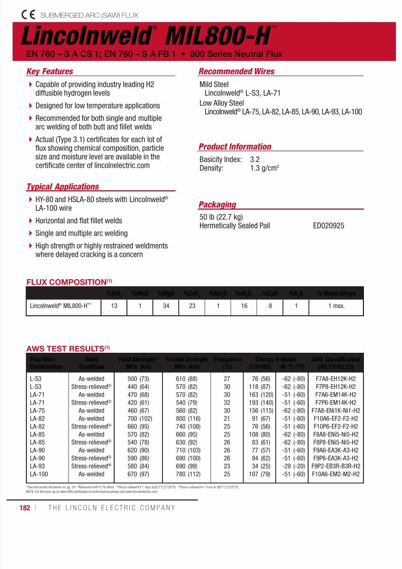
7/18/2019 c110 - Lincoln Electric Consumables 2014
http://slidepdf.com/reader/full/c110-lincoln-electric-consumables-2014 182/511182 ı T H E L I N C O L N E L E C T R I C C O M P A N Y
Lincolnweld ®
MIL800-H ™
Recommended Wires
Typical Applications
Mild SteelLincolnweld® L-S3, LA-71
Low Alloy SteelLincolnweld® LA-75, LA-82, LA-85, LA-90, LA-93, LA-100
HY-80 and HSLA-80 steels with Lincolnweld® LA-100 wire
Horizontal and flat fillet welds
Single and multiple arc welding
High strength or highly restrained weldmentswhere delayed cracking is a concern
Capable of providing industry leading H2diffusible hydrogen levels
Designed for low temperature applications
Recommended for both single and multiplearc welding of both butt and fillet welds
Actual (Type 3.1) certificates for each lot offlux showing chemical composition, particlesize and moisture level are available in thecertificate center of lincolnelectric.com
Product Information
Basicity Index: 3.2Density: 1.3 g/cm3
EN 760 – S A CS 1; EN 760 – S A FB 1 • 800 Series Neutral Flux
Key Features
Packaging
50 lb (22.7 kg)Hermetically Sealed Pail ED020925
AWS TEST RESULTS(1)
Flux/WireCombination
WeldCondition
Yield Strength(2) Tensile Strength Elongation(%)
Charpy V-Notch AWS Classification(A5.17/A5.23)MPa (ksi) MPa (ksi) J (ft•lbf) @ °C (°F)
L-S3
L-S3LA-71
LA-71
LA-75
LA-82
LA-82
LA-85
LA-85
LA-90
LA-90
LA-93
LA-100
As-welded
Stress-relieved(3)
As-welded
Stress-relieved(3)
As-welded
As-welded
Stress-relieved(3)
As-welded
Stress-relieved(3)
As-welded
Stress-relieved(3)
Stress-relieved(4)
As-welded
500
440470
420
460
700
660
570
540
620
590
580
670
(73)
(64)(68)
(61)
(67)
(102)
(95)
(82)
(78)
(90)
(86)
(84)
(97)
610
570570
540
560
800
740
660
630
710
690
690
780
(88)
(82)(82)
(79)
(82)
(116)
(108)
(95)
(92)
(103)
(100)
(99)
(112)
27
3030
32
30
21
25
25
26
26
26
23
25
76
118163
193
156
91
76
108
83
77
84
34
107
(56)
(87)(120)
(140)
(115)
(67)
(56)
(80)
(61)
(57)
(62)
(25)
(79)
-62
-62-51
-51
-62
-51
-51
-62
-62
-51
-51
-29
-51
(-80)
(-80)(-60)
(-60)
(-80)
(-60)
(-60)
(-80)
(-80)
(-60)
(-60)
(-20)
(-60)
F7A8-EH12K-H2
F7P8-EH12K-H2F7A6-EM14K-H2
F7P6-EM14K-H2
F7A8-ENi1K-Ni1-H2
F10A6-EF2-F2-H2
F10P6-EF2-F2-H2
F8A8-ENi5-Ni5-H2
F8P8-ENi5-Ni5-H2
F9A6-EA3K-A3-H2
F9P6-EA3K-A3-H2
F9P2-EB3R-B3R-H2
F10A6-EM2-M2-H2
(1)See test results disclaimer on pg. 18. (2)Measured with 0.2% offset. (3)Stress-relieved for 1 hour at 621°C (1150°F). (4)Stress-relieved for 1 hour at 691°C (1275°F).NOTE: For the most up-to-date AWS certificates of conformances please visit www.lincolnelectric.com
FLUX COMPOSITION(1)
%SiO2 %MnO %MgO %CaF2 %Na2O %Al2O3 %CaO %K 2O % Metal Alloys
Lincolnweld® MIL800-H™ 13 1 34 23 1 16 8 1 1 max.
SUBMERGED ARC (SAW) FLUX

7/18/2019 c110 - Lincoln Electric Consumables 2014
http://slidepdf.com/reader/full/c110-lincoln-electric-consumables-2014 183/511W E L D I N G C O N S U M A B L E S C A TA L O G ı 183
SUBMERGED ARC (SAW) FLUX
Packaging
50 lb (22.7 kg) Plastic Bag
Lincolnweld ®
812-SRC ™
Typical Applications
Offshore applications with extendedpost-weld heat treatment (PWHT)
Quench and tempered steels such as AISI4130, 8620, and similar chemistries
Carbon-neutral flux designed to provideexcellent mechanical properties after extendedstress-relief
Industry leading low H4 diffusible hydrogenlevels
Smooth bead appearance and excellent slagrelease
Excellent resistance to moisture pick up.
Actual (Type 3.1) certificates for each lot offlux showing chemical composition, particlesize and moisture level are available in the
certificate center of lincolnelectric.com
Recommended Wires
Low Alloy ElectrodesLincolnweld® LA-84
Product Information
Basicity Index: 2.2Density: 1.3 g/cm3
800 Series Neutral Flux • EN 760 - S A FB 1
Key Features
ED034171
FLUX COMPOSITION(1)
%SiO2
%MnO %MgO %CaF2
Lincolnweld® 812-SRC™ 16 3 30 19
%Na2O %Al2O3 %CaO % Metal AlloysLincolnweld® 812-SRC™ 2 22 4 3 max.
AWS TEST RESULTS(1)
Flux/WireCombination
WeldCondition
Yield Strength(2) Tensile Strength Elongation(%)
Charpy V-Notch AWS Classification(A5.17/A5.23)MPa (ksi) MPa (ksi) J (ft•lbf) @ °C (°F)
LA-84 As-welded 680 (98) 790 (114) 24 87 (64) -51 (-60) F10A6-EF3-F3-H4
F9P6-RF3-F3-H$(1)See test results disclaimer on pg. 18. (2)Measured with 0.2% offset.
NOTE 1: For the most up-to-date AWS certificates of conformances please visit w ww.lincolnelectric.com

7/18/2019 c110 - Lincoln Electric Consumables 2014
http://slidepdf.com/reader/full/c110-lincoln-electric-consumables-2014 184/511184 ı T H E L I N C O L N E L E C T R I C C O M P A N Y
Lincolnweld ®
960 ®
Recommended Wires
Typical Applications
Mild SteelLincolnweld® L-50®, L-61®, LA-71
Low Alloy SteelLincolnweld® LA-75, LA-85, LA-93, LA-100
Single and multiple pass welding
Fillet and butt welds with unlimited plate thickness
Can weld steel with heavy scale or rustwhen used with Lincolnweld® L-50® wire
Weathering steels when used withLincolnweld® LA-75 wire
Low cost, general purpose flux designed toweld butt joints and both single and multiplepass fillets
Recommended for automatic andsemiautomatic submerged arc welding
A versatile, cost-effective flux that can beused with many alloy systems
Can be used on A588 weathering steelswhen combined with Lincolnweld® LA-75
Actual (Type 3.1) certificates for each lot offlux showing chemical composition, particle
size and moisture level are available in thecertificate center of lincolnelectric.com
Product Information
Basicity Index: 1.1Density: 1.4 g/cm3
EN 760 – S A AB 1 • Special Neutral Flux
Key Features
Packaging
50 lb (22.7 kg) Bag ED022412
AWS D1.8 and FEMA 353
Approved when paired with the following wires:• 3/32 in (2.4 mm) Lincolnweld® L-56®
• 1/8 in (3.2 mm) Lincolnweld® L-61®
• 1/8 in (3.2 mm) Lincolnweld® LA-85
AWS TEST RESULTS(1)
Flux/WireCombination
WeldCondition
Yield Strength(2) Tensile Strength Elongation(%)
Charpy V-Notch AWS Classification(A5.17/A5.23)MPa (ksi) MPa (ksi) J (ft•lbf) @ °C (°F)
L-50®
L-61®
LA-71
LA-71
LA-75
LA-75
LA-85
LA-85
LA-93
LA-100
As-welded
As-welded
As-welded
Stress-relieved(3)
As-welded
Stress-relieved(3)
As-welded
Stress-relieved(3)
Stress-relieved(4)
As-welded
460
420
460
420
480
420
520
500
580
680
(66)
(61)
(66)
(61)
(69)
(61)
(76)
(73)
(84)
(99)
570
520
570
540
600
550
640
610
680
740
(83)
(75)
(82)
(79)
(87)
(80)
(93)
(88)
(98)
(108)
27
32
29
31
30
29
24
25
22
25
58
125
44
89
76
53
57
39
65
33
(43)
(92)
(32)
(66)
(56)
(39)
(42)
(29)
(48)
(24)
-29
-29
-29
-29
-29
-51
-29
-46
-18
-40
(-20)
(-20)
(-20)
(-20)
(-20)
(-60)
(-20)
(-50)
(0)
(-40)
F7A2-EM13K-H8
F7A2-EM12K-H8
F7A2-EM14K-H8
F7P2-EM14K-H8
F8A2-ENi1K-Ni1-H8
F7P6-ENi1K-Ni1-H8
F8A2-ENi5-G-H8
F7P5-ENi5-G-H8
F9P0-EB3R-G-H8
F10A4-EM2-G-H8
(1)See test results disclaimer on pg. 18. (2)Measured with 0.2% offset. (3)Stress-relieved for 1 hour at 621°C (1150°F). (4)Stress-relieved for 1 hour at 691°C (1275°F).NOTE: For the most u p-to-date AWS certificates of conformances please visit www.lincolnelectric.com
FLUX COMPOSITION(1)
%SiO2
%MnO %MgO %CaF2
%Na2O %Al
2O
3%CaO %TiO
2% Metal Alloys
Lincolnweld® 960® 21 10 21 10 2 31 1 1 3 max.
SUBMERGED ARC (SAW) FLUX

7/18/2019 c110 - Lincoln Electric Consumables 2014
http://slidepdf.com/reader/full/c110-lincoln-electric-consumables-2014 185/511W E L D I N G C O N S U M A B L E S C A TA L O G ı 185
SUBMERGED ARC (SAW) FLUX Structural Welding Code
Seismic Supplement
Recommended Wires
Mild SteelLincolnweld® L-50®, L-61®, LC-72
Low Alloy SteelLincolnweld® LA-75, LAC-Ni2
Product Information
Basicity Index: 0.6Density: 1.4 g/cm3
Packaging
50 lb (22.7 kg) Bag ED027861
Lincolnweld ®
980 ™
Typical Applications
Semiautomatic, single and multiple passsubmerged arc welding
General purpose fabrication
Fillet welds
Combines many of the features of the 700and 800 series fluxes and is ideal forsemiautomatic submerged arc welding
Exceptional resistance to flash-throughand porosity caused by arc blow in avariety of applications
Especially high productivity when usedwith Lincolnweld® LC-72 wire
Actual (Type 3.1) certificates for each lot offlux showing chemical composition, particlesize and moisture level are available in the
certificate center of lincolnelectric.com
Special Neutral Flux • EN 760 – S A AB 1; EN 760 – S A AR 1
Key Features
AWS TEST RESULTS(1)
Flux/WireCombination
WeldCondition
Yield Strength(2) Tensile Strength Elongation(%)
Charpy V-Notch AWS Classification(A5.17/A5.23)MPa (ksi) MPa (ksi) J (ft•lbf) @ °C (°F)
L-50®
L-61®
LC-72
LA-75
LAC-Ni2
As-welded
As-welded
As-welded
As-welded
As-welded
430
430
450
510
540
(63)
(63)
(65)
(74)
(79)
540
530
540
600
630
(78)
(77)
(78)
(87)
(91)
31
31
28
28
25
43
37
43
61
110
(32)
(27)
(32)
(45)
(81)
-29
-29
-29
-29
-29
(-20)
(-20)
(-20)
(-20)
(-20)
F7A2-EM13K-H8
F7A2-EM12K-H8
F7A2-EC1-H8
F7A2-ENi1K-Ni1-H8
F8A2-ECNi2-Ni2-H8
(1)See test results disclaimer on pg. 18. (2)Measured with 0.2% offset.NOTE: For the most up-to-date AWS certificates of conformances please visit www.lincolnelectric.com
FLUX COMPOSITION(1)
%SiO2
%MnO %MgO %CaF2
%Na2O %Al
2O
3%TiO
2% Metal Alloys
Lincolnweld® 980™ 11 14 2 12 2 47 7 4 max.
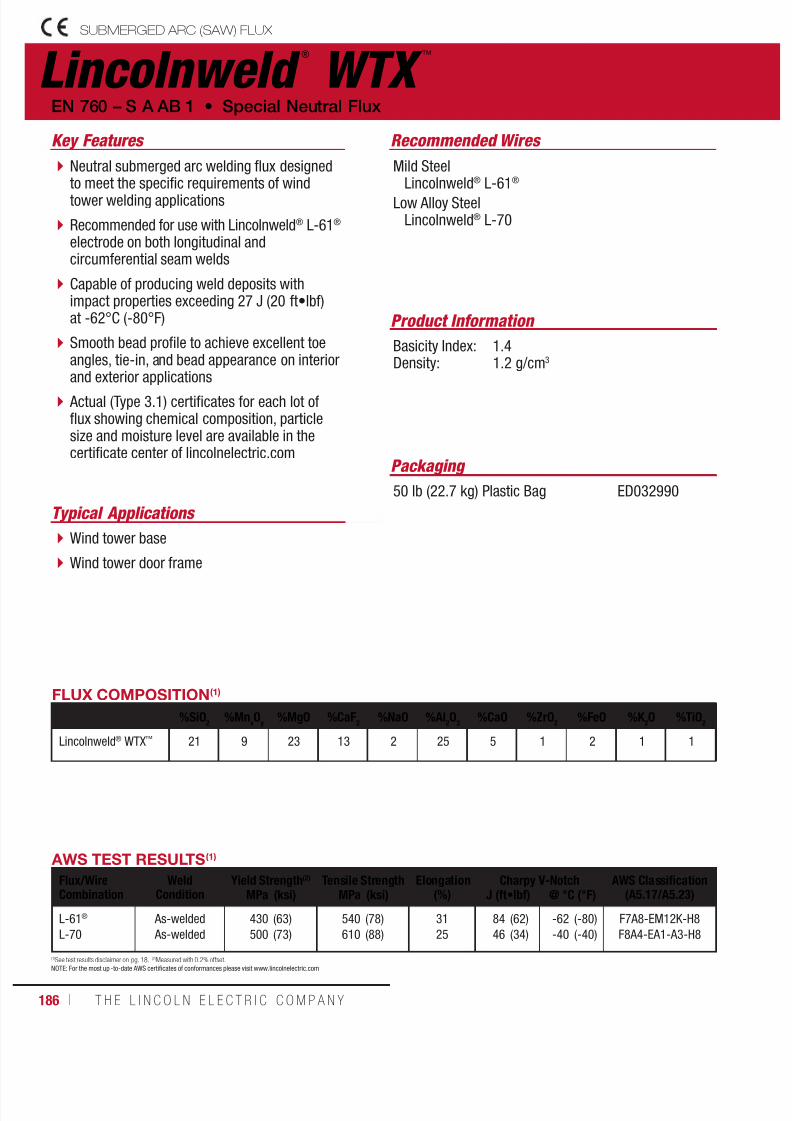
7/18/2019 c110 - Lincoln Electric Consumables 2014
http://slidepdf.com/reader/full/c110-lincoln-electric-consumables-2014 186/511186 ı T H E L I N C O L N E L E C T R I C C O M P A N Y
Lincolnweld ®
WTX ™
Recommended Wires
Typical Applications
Mild SteelLincolnweld® L-61®
Low Alloy SteelLincolnweld® L-70
Wind tower base
Wind tower door frame
Neutral submerged arc welding flux designedto meet the specific requirements of windtower welding applications
Recommended for use with Lincolnweld® L-61® electrode on both longitudinal andcircumferential seam welds
Capable of producing weld deposits withimpact properties exceeding 27 J (20 ft•lbf)at -62°C (-80°F)
Smooth bead profile to achieve excellent toeangles, tie-in, and bead appearance on interior
and exterior applications Actual (Type 3.1) certificates for each lot offlux showing chemical composition, particlesize and moisture level are available in thecertificate center of lincolnelectric.com
Product Information
Basicity Index: 1.4Density: 1.2 g/cm3
EN 760 – S A AB 1 • Special Neutral Flux
Key Features
Packaging
50 lb (22.7 kg) Plastic Bag ED032990
AWS TEST RESULTS(1)
Flux/WireCombination
WeldCondition
Yield Strength(2) Tensile Strength Elongation(%)
Charpy V-Notch AWS Classification(A5.17/A5.23)MPa (ksi) MPa (ksi) J (ft•lbf) @ °C (°F)
L-61®
L-70
As-welded
As-welded
430
500
(63)
(73)
540
610
(78)
(88)
31
25
84
46
(62)
(34)
-62
-40
(-80)
(-40)
F7A8-EM12K-H8
F8A4-EA1-A3-H8
(1)See test results disclaimer on pg. 18. (2)Measured with 0.2% offset.NOTE: For the most up -to-date AWS certificates of conformances please visit www.lincolnelectric.com
FLUX COMPOSITION(1)
%SiO2
%MnxO
y%MgO %CaF
2%NaO %Al
2O
3%CaO %ZrO
2%FeO %K
2O %TiO
2
Lincolnweld® WTX™ 21 9 23 13 2 25 5 1 2 1 1
SUBMERGED ARC (SAW) FLUX
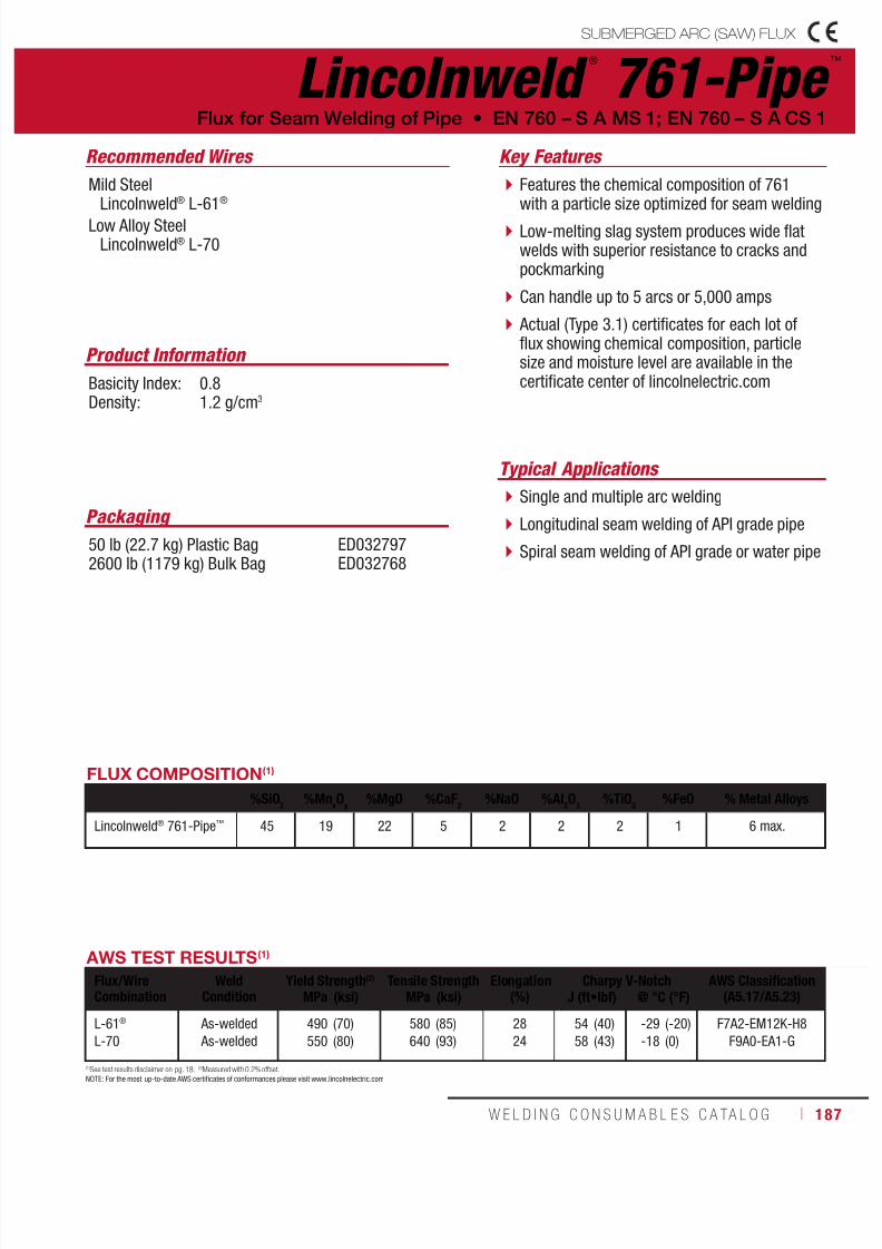
7/18/2019 c110 - Lincoln Electric Consumables 2014
http://slidepdf.com/reader/full/c110-lincoln-electric-consumables-2014 187/511W E L D I N G C O N S U M A B L E S C A TA L O G ı 187
SUBMERGED ARC (SAW) FLUX
Lincolnweld ®
761-Pipe ™
Recommended Wires
Typical Applications
Mild SteelLincolnweld® L-61®
Low Alloy SteelLincolnweld® L-70
Single and multiple arc welding
Longitudinal seam welding of API grade pipe
Spiral seam welding of API grade or water pipe
Features the chemical composition of 761with a particle size optimized for seam welding
Low-melting slag system produces wide flatwelds with superior resistance to cracks andpockmarking
Can handle up to 5 arcs or 5,000 amps
Actual (Type 3.1) certificates for each lot offlux showing chemical composition, particlesize and moisture level are available in thecertificate center of lincolnelectric.com
Product Information
Basicity Index: 0.8Density: 1.2 g/cm3
Flux for Seam Welding of Pipe • EN 760 – S A MS 1; EN 760 – S A CS 1
Key Features
Packaging
50 lb (22.7 kg) Plastic Bag2600 lb (1179 kg) Bulk Bag
ED032797ED032768
AWS TEST RESULTS(1)
Flux/WireCombination
WeldCondition
Yield Strength(2) Tensile Strength Elongation(%)
Charpy V-Notch AWS Classification(A5.17/A5.23)MPa (ksi) MPa (ksi) J (ft•lbf) @ °C (°F)
L-61®
L-70
As-welded
As-welded
490
550
(70)
(80)
580
640
(85)
(93)
28
24
54
58
(40)
(43)
-29
-18
(-20)
(0)
F7A2-EM12K-H8
F9A0-EA1-G
(1)See test results disclaimer on pg. 18. (2)Measured with 0.2% offset.NOTE: For the most up-to-date AWS certificates of conformances please visit www.lincolnelectric.com
FLUX COMPOSITION(1)
%SiO2
%MnxO
y%MgO %CaF
2%NaO %Al
2O
3%TiO
2%FeO % Metal Alloys
Lincolnweld® 761-Pipe™ 45 19 22 5 2 2 2 1 6 max.
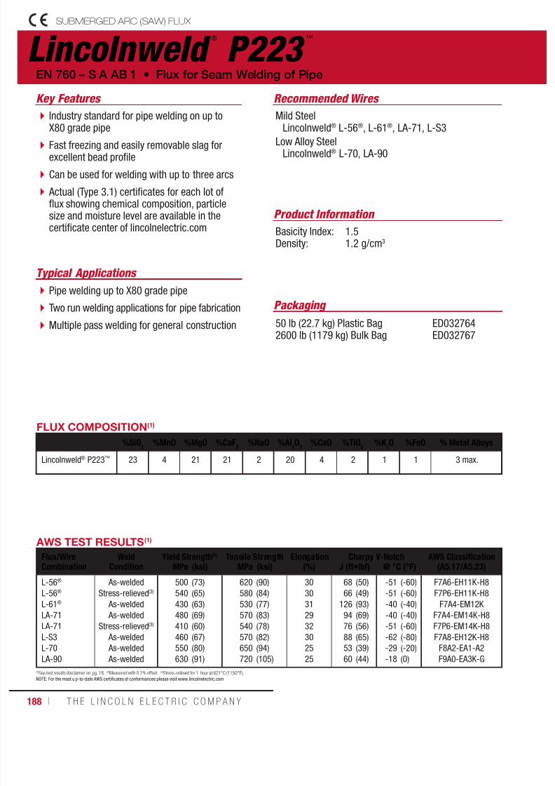
7/18/2019 c110 - Lincoln Electric Consumables 2014
http://slidepdf.com/reader/full/c110-lincoln-electric-consumables-2014 188/511188 ı T H E L I N C O L N E L E C T R I C C O M P A N Y
Lincolnweld ®
P223 ™
Recommended Wires
Typical Applications
Mild SteelLincolnweld® L-56®, L-61®, LA-71, L-S3
Low Alloy SteelLincolnweld® L-70, LA-90
Pipe welding up to X80 grade pipe
Two run welding applications for pipe fabrication
Multiple pass welding for general construction
Industry standard for pipe welding on up toX80 grade pipe
Fast freezing and easily removable slag forexcellent bead profile
Can be used for welding with up to three arcs
Actual (Type 3.1) certificates for each lot offlux showing chemical composition, particlesize and moisture level are available in thecertificate center of lincolnelectric.com
Product Information
Basicity Index: 1.5Density: 1.2 g/cm3
EN 760 – S A AB 1 • Flux for Seam Welding of Pipe
Key Features
Packaging
50 lb (22.7 kg) Plastic Bag2600 lb (1179 kg) Bulk Bag
ED032764ED032767
AWS TEST RESULTS(1)
Flux/WireCombination
WeldCondition
Yield Strength(2) Tensile Strength Elongation(%)
Charpy V-Notch AWS Classification(A5.17/A5.23)MPa (ksi) MPa (ksi) J (ft•lbf) @ °C (°F)
L-56®
L-56®
L-61®
LA-71
LA-71
L-S3
L-70
LA-90
As-welded
Stress-relieved(3)
As-welded
As-welded
Stress-relieved(3)
As-welded
As-welded
As-welded
500
540
430
480
410
460
550
630
(73)
(65)
(63)
(69)
(60)
(67)
(80)
(91)
620
580
530
570
540
570
650
720
(90)
(84)
(77)
(83)
(78)
(82)
(94)
(105)
30
30
31
29
32
30
25
25
68
66
126
94
76
88
53
60
(50)
(49)
(93)
(69)
(56)
(65)
(39)
(44)
-51
-51
-40
-40
-51
-62
-29
-18
(-60)
(-60)
(-40)
(-40)
(-60)
(-80)
(-20)
(0)
F7A6-EH11K-H8
F7P6-EH11K-H8
F7A4-EM12K
F7A4-EM14K-H8
F7P6-EM14K-H8
F7A8-EH12K-H8
F8A2-EA1-A2
F9A0-EA3K-G
(1)See test results disclaimer on pg. 18. (2)Measured with 0.2% offset. (3)Stress-relieved for 1 hour at 621°C (1150°F).NOTE: For the most u p-to-date AWS certificates of conformances please visit www.lincolnelectric.com
FLUX COMPOSITION(1)
%SiO2
%MnO %MgO %CaF2
%NaO %Al2O
3%CaO %TiO
2%K
2O %FeO % Metal Alloys
Lincolnweld® P223™ 23 4 21 21 2 20 4 2 1 1 3 max.
SUBMERGED ARC (SAW) FLUX

7/18/2019 c110 - Lincoln Electric Consumables 2014
http://slidepdf.com/reader/full/c110-lincoln-electric-consumables-2014 189/511W E L D I N G C O N S U M A B L E S C A TA L O G ı 189
SUBMERGED ARC (SAW) FLUX
Lincolnweld ®
SPX80 ™
Recommended Wires
Typical Applications
Mild SteelLincolnweld® L-61®
Low Alloy SteelLincolnweld® L-70, LA-81, LA-90
Spiral pipe mills
Weld up to API X80 pipe
Two run weldingapplications
Designed to meet the specific requirementsof spiral pipe seam welding of up to API X80grade pipe
High speed welding capability for increasedproductivity
Capable of producing weld deposits withimpact properties exceeding 27 J (20 ft•lbf)at -51°C (-60°F) with Lincolnweld® LA-81
Smooth bead profile achieves optimalappearance on both inner and outerdiameter welds
Self-peeling slag allows for clean and easyslag removal for reliable non-destructivetesting results
Actual (Type 3.1) certificates for each lot offlux showing chemical composition, particlesize and moisture level are available in thecertificate center of lincolnelectric.com
Product Information
Basicity Index: 1.3Density: 1.2 g/cm3
Flux for Seam Welding of Pipe • EN 760 – S A AB 1
Key Features
Packaging
50 lb (22.7 kg) Plastic Bag2600 lb (1179 kg) Bulk Bag
ED032960ED033319
AWS TEST RESULTS(1) - MULTI-PASS
Flux/WireCombination
WeldCondition
Yield Strength(2) Tensile Strength Elongation(%)
Charpy V-Notch AWS Classification(A5.17/A5.23)MPa (ksi) MPa (ksi) J (ft•lbf) @ °C (°F)
L-61®
L-70
LA-90
As-Welded
As-Welded
As-Welded
430
530
610
(62)
(77)
(89)
543
620
720
(79)
(89)
(105)
31
25
25
94
68
39
(69)
(50)
(29)
-46
-40
-40
(-50)
(-40)
(-40)
F7A5-EM12K-H8
F8A4-EA1-A4-H8
F8A4-EA1-A4-H8
FLUX COMPOSITION(1)
%SiO2
%MnO %MgO %CaF2
%NaO %Al2O
3%CaO %ZrO
2%FeO %TiO
2
Lincolnweld® SPX80™ 23 9 21 14 2 25 2 2 1 1
AWS TEST RESULTS(1) - TWO RUN
Flux/WireCombination
SteelType
WeldCondition
Yield Strength(2) Tensile Strength Elongation(%)
Charpy V-Notch AWS Classification(A5.17/A5.23)MPa (ksi) MPa (ksi) J (ft•lbf) @ °C (°F)
L-61®
L-70
L-70
LA-81
LA-81
LA-90
LA-90
LA-90
A131
A131
X65
X65
X80
X65
X70
X80
As-welded
As-welded
As-welded
As-welded
As-welded
As-welded
As-welded
As-welded
460
500
560
580
630
590
580
630
(67)
(72)
(82)
(84)
(92)
(86)
(85)
(93)
600
620
650
680
690
690
700
690
(87)
(89)
(94)
(98)
(101)
(101)
(102)
(100)
30
27
26
25
26
24
27
27
45
38
88
43
114
37
113
72
(33)
(28)
(65)
(32)
(84)
(27)
(83)
(53)
-18
-40
-40
-40
-51
-51
-40
-40
(0)
(-40)
(-40)
(-40)
(-60)
(-60)
(-40)
(-40)
F7TA0-EM12K
F7TA4-EA1
F8TA4G-EA1
F9TA4G-EG
F9TA6G-EG
F9TA6G-EA3K
F9TA4G-EA3K
F9TA4G-EA3K
(1)See test results disclaimer on pg. 18. (2)Measured with 0.2% offset.NOTE: For the most up-to-date AWS certificates of conformances please visit www.lincolnelectric.com

7/18/2019 c110 - Lincoln Electric Consumables 2014
http://slidepdf.com/reader/full/c110-lincoln-electric-consumables-2014 190/511190 ı T H E L I N C O L N E L E C T R I C C O M P A N Y
Lincolnweld ®
995N ™
Recommended Wires
Typical Applications
Mild SteelLincolnweld® L-61®
Low Alloy SteelLincolnweld® L-70, LA-81, LA-90
Automatic, single pass welding
Single or multiple arc welding
High speed longitudinal seam welding ona range of pipe steels
One side welding requiring impact properties
A nitrogen limiting flux designed for seamwelding of pipe
Recommended for automatic single passwelding with up to five arcs
Produces welds with minimal buildup andgood penetration
Capable of producing Charpy V-Notch testresults required for arctic grade service
Actual (Type 3.1) certificates for each lot offlux showing chemical composition, particlesize and moisture level are available in the
certificate center of lincolnelectric.com
Product Information
Basicity Index: 1.3Density: 1.0 g/cm3
EN 760 – S A AB 1 • Flux for Seam Welding of Pipe
Key Features
Packaging
50 lb (22.7 kg) Plastic Bag ED032831
AWS TEST RESULTS(1)
Flux/WireCombination
WeldCondition
Yield Strength(2) Tensile Strength Elongation(%)
Charpy V-Notch AWS Classification(A5.17/A5.23)MPa (ksi) MPa (ksi) J (ft•lbf) @ °C (°F)
L-61®
L-70
LA-81
LA-90
As-welded
As-welded
As-welded
As-welded
430
510
590
600
(63)
(74)
(96)
(87)
540
610
660
700
(79)
(88)
(96)
(102)
29
24
26
25
83
73
58
54
(61)
(54)
(43)
(40)
-40
-29
-29
-29
(-40)
(-20)
(-20)
(-20)
F7A4-EM12K-H8
F8A2-EA1-A4
F9A2-EG-G
F9A2-EA3K-G
FLUX COMPOSITION(1)
%SiO2
%MnO %MgO %CaF2
%Na2O %Al
2O
3%CaO %ZrO
2%FeO %TiO
2% Metal Alloys
Lincolnweld® 995N™ 19 11 16 14 3 27 5 2 1 1 3 max.
(1)See test results disclaimer on pg. 18. (2)Measured with 0.2% offset.NOTE: For the most u p-to-date AWS certificates of conformances please visit www.lincolnelectric.com
SUBMERGED ARC (SAW) FLUX

7/18/2019 c110 - Lincoln Electric Consumables 2014
http://slidepdf.com/reader/full/c110-lincoln-electric-consumables-2014 191/511W E L D I N G C O N S U M A B L E S C A TA L O G ı 191
SUBMERGED ARC (SAW) FLUX
Lincolnweld ®
A-XXX10 ™
Recommended Wires
Typical Applications
For Low Alloy Lincolnweld® L-61®
Welding of A588 weathering steels and ASTM A533-Class 1
An alloy flux designed to produce a 1%nickel-bearing weld deposit
Recommended for use on ASTM A533 Class 1and A588 weathering steels when combinedwith Lincolnweld® L-61®
Actual (Type 3.1) certificates for each lot offlux showing chemical composition, particlesize and moisture level are available in thecertificate center of lincolnelectric.com
Product Information
Basicity Index: 1.0Density: 1.4 g/cm3
High Performance / Alloy Flux • EN 760 – S A AS 1
Key Features
Packaging
50 lb (22.7 kg) Bag ED027862
AWS TEST RESULTS(1)
Flux/WireCombination
WeldCondition
Yield Strength(2) Tensile Strength Elongation(%)
Charpy V-Notch AWS Classification(A5.17/A5.23)MPa (ksi) MPa (ksi) J (ft•lbf) @ °C (°F)
L-61® As-welded 460 (67) 570 (83) 30 85 (63) -40 (-40) F7A4-EM12K-Ni1-H8
FLUX COMPOSITION(1)
%SiO2
%MnO %MgO %CaF2
%Na2O %Al
2O
3%ZrO
2%TiO
2% Metal Alloys
Lincolnweld® A-XXX10™ 18 5 22 11 2 19 22 1 5 max.
(1)See test results disclaimer on pg. 18. (2)Measured with 0.2% offset.NOTE: For the most up-to-date AWS certificates of conformances please visit www.lincolnelectric.com
Notes
Since the alloy level in the weld deposit dependsupon the arc voltage, and thus the arc length,always maintain a consistent arc voltage. If more
flexibility in procedure is necessary, use 960 fluxand LA-75 electrode.

7/18/2019 c110 - Lincoln Electric Consumables 2014
http://slidepdf.com/reader/full/c110-lincoln-electric-consumables-2014 192/511192 ı T H E L I N C O L N E L E C T R I C C O M P A N Y
SUBMERGED ARC (SAW) FLUX
Lincolnweld ®
MIL800-HPNi ™
Recommended Wires
Typical Applications
Low Alloy Steel Lincolnweld® LA-75, LA-85, LA-100
Bridge fabrication with HPS70W steel, whenused with LA-85 wire
Single or multiple wire arc welding
Butt and fillet welds on low alloy steels
When used with Lincolnweld® LA-85 thenickel content will increase from a nominal1% to a minimum 1%
Use on high performance steel applications,including HPS70W or HPS100W
Capable of producing ultra low H2 diffusiblehydrogen levels on HPS steels
Actual (Type 3.1) certificates for each lot of fluxshowing chemical composition, particle sizeand moisture level are available in the certifi-cate center of lincolnelectric.com
Product Information
Basicity Index: 3.1Density: 1.3 g/cm3
EN 760 - S A FB 1 • High Performance / Alloy Flux
Key Features
Packaging
50 lb (22.7 kg)Hermetically Sealed Pail ED028657
AWS TEST RESULTS(1)
Flux/WireCombination
WeldCondition
Yield Strength(2) Tensile Strength Elongation(%)
Charpy V-Notch AWS Classification(A5.17/A5.23)MPa (ksi) MPa (ksi) J (ft•lbf) @ °C (°F)
LA-75
LA-85
LA-100
As-welded
As-welded
As-welded
560
600
800
(81)
(88)
(116)
640
690
850
(93)
(100)
(123)
28
25
23
145
143
91
(107)
(105)
(67)
-51
-40
-40
(-60)
(-40)
(-40)
F8A6-ENi1K-G-H2
F9A4-ENi5-G-H2
F11A4-EM2-G-H2
FLUX COMPOSITION(1)
%SiO2
%MgO %CaF2
%Na2O %Al
2O
3%CaO %TiO
2%K
2O %FeO % Metal Alloys
Lincolnweld® MIL800-HPNi™ 13 34 22 1 16 8 2 1 1 3 max.
(1)See test results disclaimer on pg. 18. (2)Measured with 0.2% offset.NOTE: For the most u p-to-date AWS certificates of conformances please visit www.lincolnelectric.com

7/18/2019 c110 - Lincoln Electric Consumables 2014
http://slidepdf.com/reader/full/c110-lincoln-electric-consumables-2014 193/511W E L D I N G C O N S U M A B L E S C A TA L O G ı 193
WIRE COMPOSITION(1) - As Required per AWS A5.17/A5.17M:1997 %C %Mn %Si %S %P %Cu
Lincolnweld® L-50® 0.06-0.16 0.90-1.40 0.35-0.75 0.030 0.030 0.35
DIAMETERS / PACKAGINGDiameter 60 lb (27.2 kg)
Coil600 lb (272 kg)
Speed Feed® Drum1000 lb (453 kg)
Speed Feed® Drum1000 lb (453 kg)
Accu-Trak® Drum2200 lb (998 kg)
Speed Feed® Stemin. (mm)
1/165/643/321/8
5/32
(1.6)(2.0)(2.4)(3.2)(4.0)
ED011317ED011335ED011328ED011323ED011332
ED011316ED011334ED011327ED011322ED011331
ED029083
ED033481ED032997
Lincolnweld ®
L-50 ®
Recommended Fluxes
Lincolnweld® 760®, 761®, 780®, 781®, 860®, 865™,880M®, 882™, 888™, 8500™, 960®, 980™, P223™
A low carbon, medium manganese, medium silicon wire
Pair it with Lincolnweld® 980™ flux for the best flux/ wire combination when semiautomatic submerged arcwelding
Actual (Type 3.1) certificates for each lot of wireshowing chemical composition are available in thecertificate center of lincolnelectric.com
Mild Steel Solid Electrode • AWS EM13K
Key Features Conformances
AWS A5.17/A5.17M: 1997
MIL-E-23765/1D &1E:EN 756:
EM13K
MIL-70S-3SZ
Recommended Fluxes
Lincolnweld® 860®, 880M®, 882™, 888™,8500™, P223™
A low carbon, high manganese, very high silicon wire
Can be used with Lincolnweld® 800 seriesfluxes for welds requiring 480 MPa (70 ksi) tensilestrength in stress relieved conditions
Actual (Type 3.1) certificates for each lot of wireshowing chemical composition are available in thecertificate center of lincolnelectric.com
Key Features Conformances
AWS A5.17/A5.17M: 1997
MIL-E-23765/1D & 1E:
EN 756:
EH11K
MIL-70S-6
SZ
WIRE COMPOSITION(1) - As Required per AWS A5.17/A5.17M:1997
%C %Mn %Si %S %P %Cu
Lincolnweld® L-56® 0.06-0.15 1.40-1.85 0.80-1.15 0.030 0.030 0.35
DIAMETERS / PACKAGING
Diameter 60 lb (27.2 kg)Coil
Accu-Trak® Drum 1000 lb (453 kg)Speed Feed® Reel
1000 lb (453 kg)Speed Feed® Drum
2200 lb (998 kg)Speed Feed® Stemin. (mm) 500 lb (227 kg) 1000 lb (453 kg)
1/165/643/321/8
5/32
(1.6)(2.0)(2.4)(3.2)(4.0)
ED011666ED011678ED011674ED011671EDS11677
ED029225 ED029085EDS01631
ED030425ED030426ED028264
ED032998ED032999
(1)Single values are maximums.
Lincolnweld ®
L-56 ®
Mild Steel Solid Electrode • AWS EH11K
SUBMERGED ARC (SAW) ELECTRODE
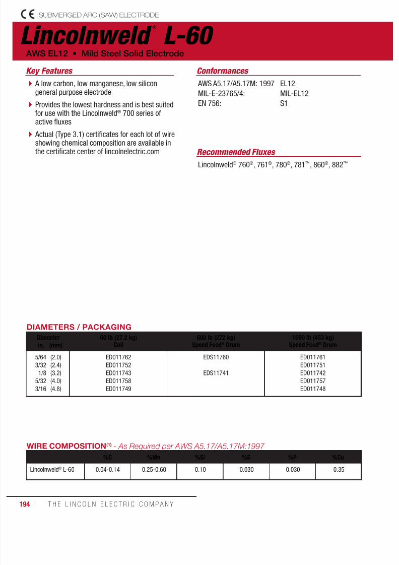
7/18/2019 c110 - Lincoln Electric Consumables 2014
http://slidepdf.com/reader/full/c110-lincoln-electric-consumables-2014 194/511194 ı T H E L I N C O L N E L E C T R I C C O M P A N Y
SUBMERGED ARC (SAW) ELECTRODE
Lincolnweld ®
L-60
Recommended Fluxes
Lincolnweld® 760®, 761®, 780®, 781™, 860®, 882™
A low carbon, low manganese, low silicongeneral purpose electrode
Provides the lowest hardness and is best suitedfor use with the Lincolnweld® 700 series ofactive fluxes
Actual (Type 3.1) certificates for each lot of wireshowing chemical composition are available inthe certificate center of lincolnelectric.com
AWS EL12 • Mild Steel Solid Electrode
Key Features Conformances
AWS A5.17/A5.17M: 1997
MIL-E-23765/4:EN 756:
EL12
MIL-EL12S1
WIRE COMPOSITION(1) - As Required per AWS A5.17/A5.17M:1997
%C %Mn %Si %S %P %Cu
Lincolnweld® L-60 0.04-0.14 0.25-0.60 0.10 0.030 0.030 0.35
DIAMETERS / PACKAGING
Diameter 60 lb (27.2 kg)Coil
600 lb (272 kg)Speed Feed® Drum
1000 lb (453 kg)Speed Feed® Drumin. (mm)
5/64
3/32
1/8
5/32
3/16
(2.0)
(2.4)
(3.2)
(4.0)
(4.8)
ED011762
ED011752
ED011743
ED011758
ED011749
EDS11760
EDS11741
ED011761
ED011751
ED011742
ED011757
ED011748
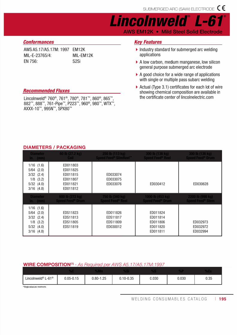
7/18/2019 c110 - Lincoln Electric Consumables 2014
http://slidepdf.com/reader/full/c110-lincoln-electric-consumables-2014 195/511W E L D I N G C O N S U M A B L E S C A TA L O G ı 195
Recommended Fluxes
Lincolnweld® 760®, 761®, 780®, 781™, 860®, 865™,882™, 888™, 761-Pipe™, P223™, 960®, 980™, WTX™, AXXX-10™, 995N™, SPX80™
Conformances
AWS A5.17/A5.17M: 1997
MIL-E-23765/4:EN 756:
EM12K
MIL-EM12K S2Si
(1)Single values are maximums.
Industry standard for submerged arc weldingapplications
A low carbon, medium manganese, low silicongeneral purpose submerged arc electrode
A good choice for a wide range of applicationswith single or multiple pass subarc welding
Actual (Type 3.1) certificates for each lot of wireshowing chemical composition are available inthe certificate center of lincolnelectric.com
Key Features
WIRE COMPOSITION(1) - As Required per AWS A5.17/A5.17M:1997
%C %Mn %Si %S %P %Cu
Lincolnweld® L-61® 0.05-0.15 0.80-1.25 0.10-0.35 0.030 0.030 0.35
(1)Single values are maximums.
DIAMETERS / PACKAGING
Diameter 60 lb (27.2 kg)Coil
250 lb (113 kg)Speed Feed® SlimReel™
300 lb (136 kg)Speed Feed® Reel
300 lb (136 kg)Speed Feed® Drumin. (mm)
1/16
5/64
3/32
1/8
5/32
3/16
(1.6)
(2.0)
(2.4)
(3.2)
(4.0)
(4.8)
ED011803
ED011825
ED011815
ED011807
ED011821
ED011812
ED033074
ED033075
ED033076 ED030412 ED030628
Diameter 600 lb (272 kg)Speed Feed® Drum
750 lb (340 kg)Speed Feed® Reel
1000 lb (453 kg)Speed Feed® Drum
2200 lb (998 kg)Speed Feed® Stemin. (mm)
1/16
5/64
3/32
1/8
5/32
3/16
(1.6)
(2.0)
(2.4)
(3.2)
(4.0)
(4.8)
EDS11823
EDS11813
EDS11805
EDS11819
ED011826
EDS11817
EDS11809
ED030012
ED011824
ED011814
ED011806
ED011820
ED011811
ED032973
ED032972
ED032994
Lincolnweld ®
L-61®
AWS EM12K • Mild Steel Solid Electrode
SUBMERGED ARC (SAW) ELECTRODE

7/18/2019 c110 - Lincoln Electric Consumables 2014
http://slidepdf.com/reader/full/c110-lincoln-electric-consumables-2014 196/511196 ı T H E L I N C O L N E L E C T R I C C O M P A N Y
SUBMERGED ARC (SAW) ELECTRODE
Lincolnweld ®
L-S3
A low carbon, high manganese, medium silicon electrodedesigned for use with the Lincolnweld® 800 series ofneutral fluxes
Capable of producing weld deposits with impact propertiesexceeding 27 J (20 ft•lbf) at -62°C (-80°F) when used withLincolnweld® 888™, 8500™, and MIL800-H™ neutral fluxes
Actual (Type 3.1) certificates for each lot of wire showingchemical composition are available in the certificate centerof lincolnelectric.com
Mild Steel Solid Electrode • AWS EH12K
Key Features
Recommended Fluxes
Lincolnweld® 860®, 880M®, 882™, 888™,8500™, MIL800-H™, P223™
Conformances
AWS A5.17/A5.17M: 1997
EN 756:
EH12K
S3Si
WIRE COMPOSITION(1) - As Required per AWS A5.17/A5.17M:1997 %C %Mn %Si %S %P %Cu
Lincolnweld® L-S3 0.06-0.15 1.50-2.0 0.25-0.65 0.025 0.025 0.35
(1)Single values are maximums.
DIAMETERS / PACKAGING
Diameter 60 lb (27.2 kg)Coilin (mm)
1/85/32
(3.2)(4.0)
ED016767ED016248
Lincolnweld ®
LA-71
A low carbon, medium manganese, mediumsilicon electrode containing approximately0.1% titanium
Small addition of titanium allows deposits to bestress-relieved with little loss of strength, evenwith extended stress relief times
Widely used with neutral basic fluxes in both
as-welded and post-weld heat treated conditions
Mild Steel Solid Electrode • AWS EM14K Key Features
Recommended Fluxes
Lincolnweld® 860®, 865™, 880M®, 882™, 888™, 8500™,MIL800-H™, 960®, P223™
Conformances
AWS A5.17/A5.17M: 1997EN 756:
EM14K SZ
WIRE COMPOSITION(1) - As Required per AWS A5.17/A5.17M:1997 %C %Mn %Si %Ti %S %P %Cu
Lincolnweld® LA-71 0.06-0.19 0.90-1.40 0.35-0.75 0.03-0.17 0.025 0.025 0.35
DIAMETERS / PACKAGING
Diameter 60 lb (27.2 kg)Coil
1000 lb (453 kg)Speed Feed® Drumin (mm)
3/321/8
5/32
(2.4)(3.2)(4.0)
ED011052ED011051ED011053
EDS30781EDS30782

7/18/2019 c110 - Lincoln Electric Consumables 2014
http://slidepdf.com/reader/full/c110-lincoln-electric-consumables-2014 197/511W E L D I N G C O N S U M A B L E S C A TA L O G ı 197
(1)Single values are maximums.
Lincolnweld ®
L-70
A low carbon, medium manganese, low silicon,1/2% molybdenum wire used for single or multiplepass welds
A standard choice for pipe fabrication andother limited pass applications
Actual (Type 3.1) certificates for each lot of wireshowing chemical composition are available in thecertificate center of lincolnelectric.com
Low Alloy Solid Electrode • AWS EA1
Key Features
Recommended Fluxes
Lincolnweld® 761®, 781™, 860®, 882™, 888™,995N™, 761-Pipe™, P223™, SPX80™
Conformances
AWS A5.23/A5.23M: 2007
MIL-E-23765/4:EN 756:
EA1
MIL-EA1S2Mo
WIRE COMPOSITION(1) - As Required per AWS A5.23/A5.23M:2007 %C %Mn %Si %Mo %S %P %Cu
Lincolnweld® L-70 0.05-0.15 0.65-1.00 0.20 0.45-0.65 0.025 0.025 0.35
DIAMETERS / PACKAGINGDiameter 60 lb (27.2 kg)
Coil1000 lb (453 kg)
Speed Feed® Drum2200 lb (998 kg)
Speed Feed® Stemin (mm)
5/641/8
5/323/16
(2.0)(3.2)(4.0)(4.8)
ED012054ED012051ED012053ED012052
ED021192ED021193EDS21194
ED032971ED032970ED032996
Lincolnweld ®
LA-75
A low carbon, medium manganese, highsilicon, nickel-bearing electrode designedfor use with Lincolnweld® neutral fluxes
Suitable for use in applications requiringless than 1% Ni wire composition
Actual (Type 3.1) certificates for each lot of wireshowing chemical composition are available in
the certificate center of lincolnelectric.com
Low Alloy Solid Electrode • AWS ENi1K Key Features
Recommended Fluxes
Lincolnweld® 860®, 865™, 880™, 880M®, 882™, 888™,MIL800-H™, MIL800-HPNi™, 960®, 980™
Conformances
AWS A5.23/A5.23M: 2007EN 756:
ENi1K SZ
WIRE COMPOSITION(1) - As Required per AWS A5.23/A5.23M:2007 %C %Mn %Si %Ni %S %P %Cu
Lincolnweld® LA-75 0.12 0.80-1.40 0.40-0.80 0.75-1.25 0.020 0.020 0.35
DIAMETERS / PACKAGING
Diameter 60 lb (27.2 kg)Coil
1000 lb (453 kg)Speed Feed® Drumin (mm)
5/643/321/8
5/32
(2.0)(2.4)(3.2)(4.0)
ED011066ED011064ED011062ED011065
ED027225
ED027224
SUBMERGED ARC (SAW) ELECTRODE

7/18/2019 c110 - Lincoln Electric Consumables 2014
http://slidepdf.com/reader/full/c110-lincoln-electric-consumables-2014 198/511198 ı T H E L I N C O L N E L E C T R I C C O M P A N Y
SUBMERGED ARC (SAW) ELECTRODE
(1)No AWS limits. Values are typical. (2)Single values are maximums.
Lincolnweld ®
LA-81
A low carbon, medium manganese, low silicon, 1/2%molybdenum wire containing small additions of titaniumand boron for improved fracture toughness Generally used in two run applications forarctic grade line pipe It can be used to weld up to API X90 grade pipe Actual (Type 3.1) certificates for each lot of wireshowing chemical composition are available in thecertificate center of lincolnelectric.com
AWS EG • Low Alloy Solid Electrode
Key Features
Recommended Fluxes
Lincolnweld® 995N™, SPX80™
Conformances
AWS A5.23/A5.23M: 2007EN ISO 26304-A:
EGSZ
WIRE COMPOSITION - As Required per AWS A5.23/A5.23M:2007 %C %Mn %Si %Mo %Ti %B %Cu
Lincolnweld® LA-81(1) 0.05 1.2 0.2 0.50 0.1 0.01 0.20
DIAMETERS / PACKAGINGDiameter 60 lb (27.2 kg)
Coil1000 lb (453 kg)
Speed Feed® Drum2200 lb (998 kg)
Speed Feed® Stemin (mm)
1/8
5/323/16
(3.2)
(4.0)(4.8)
ED023163 EDS31060
ED032993
ED032992ED032995
Lincolnweld ®
LA-82
Designed especially for high strength applications
Recommended when over 620 MPa (90 ksi) tensilestrength is required in the as-welded condition or whenlow temperature impact toughness is required in thestress-relieved condition
Actual (Type 3.1) certificates for each lot of wireshowing chemical composition are available in the
certificate center of lincolnelectric.com
AWS EF2 • Low Alloy Solid Electrode
Key Features
Recommended Fluxes
Lincolnweld® 860®, 882™, 888™, 8500™,MIL800-H™
Conformances
AWS A5.23/A5.23M: 2007EN ISO 26304-A:
EF2SZ
WIRE COMPOSITION(2) - As Required per AWS A5.23/A5.23M:2007 %C %Mn %Si %Ni %Mo %S %P %Cu
Lincolnweld® LA-82 0.10-0.18 1.70-2.40 0.2 0.40-0.80 0.40-0.65 0.025 0.025 0.35
DIAMETERS / PACKAGING
Diameter 60 lb (27.2 kg)Coilin (mm)
3/321/8
5/32
(2.4)(3.2)(4.0)
EDS30785ED026958ED026959

7/18/2019 c110 - Lincoln Electric Consumables 2014
http://slidepdf.com/reader/full/c110-lincoln-electric-consumables-2014 199/511W E L D I N G C O N S U M A B L E S C A TA L O G ı 199
Lincolnweld ®
LA-84
A nickel-bearing electrode with 1/2% molybdenum
Can be used for higher strength weldments whereimpact properties exceeding 27 J(20 ft•lbf) at -62°C (-80°F) are required
Suitable for use where consumables with less than 1%Ni are required
Actual (Type 3.1) certificates for each lot of wireshowing chemical composition are available in thecertificate center of lincolnelectric.com
Low Alloy Solid Electrode • AWS EF3
Key Features
Recommended Fluxes
Lincolnweld® 860®, 880M®, 882™, 888™, P223™,MIL800-H™, MIL800-HPNi™
Conformances
AWS A5.23/A5.23M: 2007
EN ISO 26304-A:
EF3
S3Ni1Mo
WIRE COMPOSITION(1) - As Required per AWS A5.23/A5.23M:2007 %C %Mn %Si %Ni %Mo %S %P %Cu
Lincolnweld® LA-84 0.10-0.18 1.75-2.20 0.2 0.80-1.0 0.45-0.60 0.010-0.020 0.010-0.020 0.05-0.15
DIAMETERS / PACKAGING
Diameter 60 lb (27.2 kg)Coil
1000 lb (453 kg)Speed Feed® Drumin (mm)
5/643/321/8
5/32
(2.0)(2.4)(3.2)(4.0)
ED034211ED031871ED033323ED034212
ED031872
(1)Single values are maximums.
Lincolnweld ®
LA-85
A nickel-bearing wire with 0.2% molybdenumdesigned for use on weathering steels
Capable of producing weld deposits with480-550 MPa (70-80 ksi) tensile strength inthe as-welded and stress-relieved conditions
Actual (Type 3.1) certificates for each lot of wireshowing chemical composition are available in
the certificate center of lincolnelectric.com
Low Alloy Solid Electrode • AWS ENi5
Key Features
Recommended Fluxes
Lincolnweld® 860®, 880M®, 882™, 888™, 8500™,MIL800-H™, MIL800-HPNi™, 960®
Conformances
AWS A5.23/A5.23M: 2007EN ISO 26304-A:
ENi5SZ
WIRE COMPOSITION(1) - As Required per AWS A5.23/A5.23M:2007 %C %Mn %Si %Ni %Mo %S %P %Cu
Lincolnweld® LA-85 0.12 1.20 - 1.60 0.05 - 0.30 0.75 - 1.25 0.10 - 0.30 0.025 0.020 0.35
DIAMETERS / PACKAGING
Diameter 60 lb (27.2 kg)Coil
1000 lb (453 kg)Speed Feed® Drumin (mm)
3/321/8
5/323/16
(2.4)(3.2)(4.0)(4.8)
ED023166ED023167ED023168ED023169
ED029965
SUBMERGED ARC (SAW) ELECTRODE
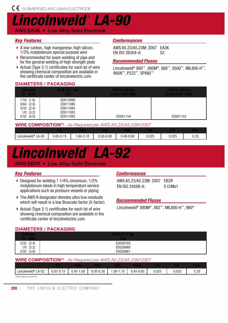
7/18/2019 c110 - Lincoln Electric Consumables 2014
http://slidepdf.com/reader/full/c110-lincoln-electric-consumables-2014 200/511
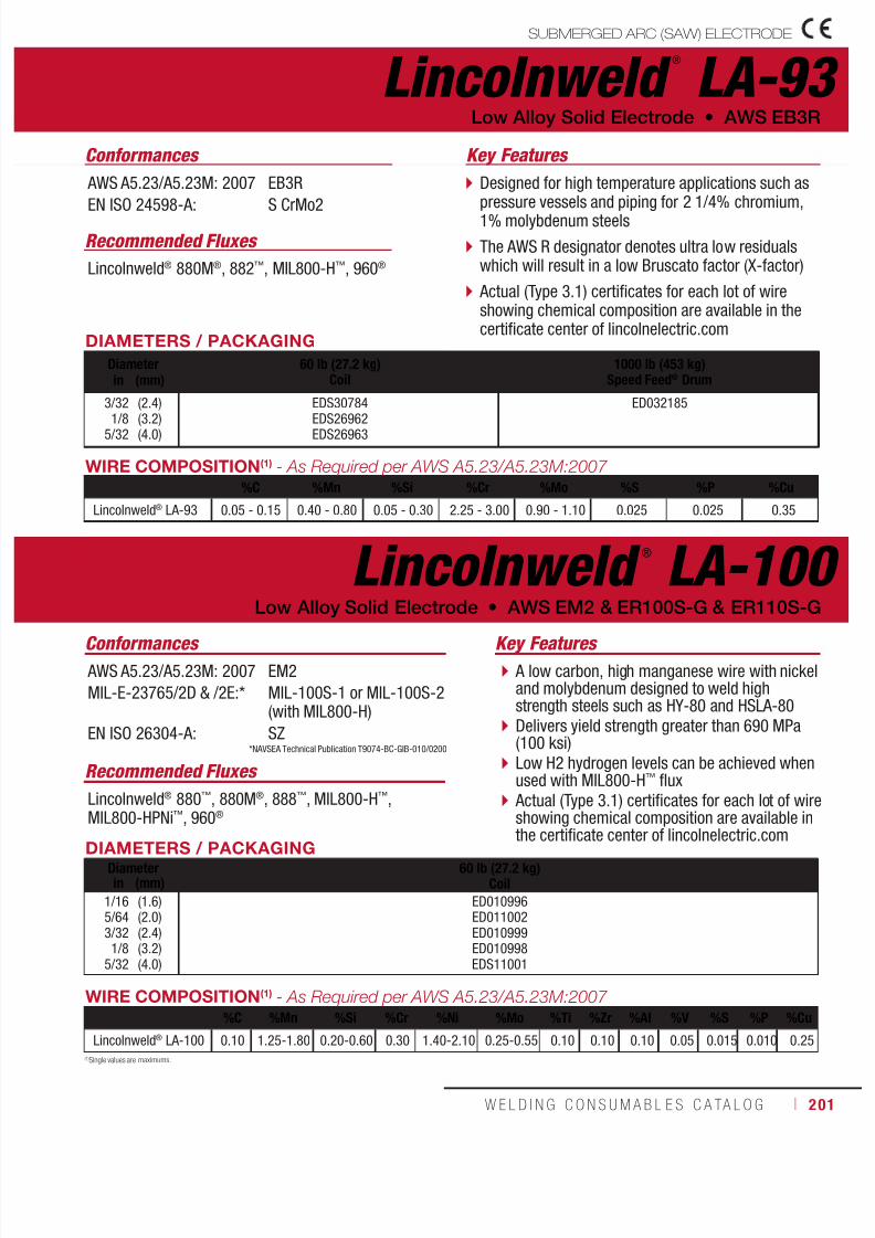
7/18/2019 c110 - Lincoln Electric Consumables 2014
http://slidepdf.com/reader/full/c110-lincoln-electric-consumables-2014 201/511W E L D I N G C O N S U M A B L E S C A TA L O G ı 201
(1)Single values are maximums.
Lincolnweld ®
LA-93
Designed for high temperature applications such aspressure vessels and piping for 2 1/4% chromium,1% molybdenum steels
The AWS R designator denotes ultra low residualswhich will result in a low Bruscato factor (X-factor)
Actual (Type 3.1) certificates for each lot of wireshowing chemical composition are available in thecertificate center of lincolnelectric.com
Low Alloy Solid Electrode • AWS EB3R
Key Features
Recommended Fluxes
Lincolnweld® 880M®, 882™, MIL800-H™, 960®
Conformances
AWS A5.23/A5.23M: 2007
EN ISO 24598-A:
EB3R
S CrMo2
DIAMETERS / PACKAGING
Diameter 60 lb (27.2 kg)Coil
1000 lb (453 kg)Speed Feed® Drumin (mm)
3/32
1/85/32
(2.4)
(3.2)(4.0)
EDS30784
EDS26962EDS26963
ED032185
WIRE COMPOSITION(1) - As Required per AWS A5.23/A5.23M:2007 %C %Mn %Si %Cr %Mo %S %P %Cu
Lincolnweld® LA-93 0.05 - 0.15 0.40 - 0.80 0.05 - 0.30 2.25 - 3.00 0.90 - 1.10 0.025 0.025 0.35
Lincolnweld ®
LA-100
A low carbon, high manganese wire with nickeland molybdenum designed to weld highstrength steels such as HY-80 and HSLA-80 Delivers yield strength greater than 690 MPa(100 ksi)
Low H2 hydrogen levels can be achieved whenused with MIL800-H™ flux Actual (Type 3.1) certificates for each lot of wireshowing chemical composition are available inthe certificate center of lincolnelectric.com
Low Alloy Solid Electrode • AWS EM2 & ER100S-G & ER110S-G
Key Features
Recommended Fluxes
Lincolnweld® 880™, 880M®, 888™, MIL800-H™,MIL800-HPNi™, 960®
Conformances
AWS A5.23/A5.23M: 2007
MIL-E-23765/2D & /2E:*
EN ISO 26304-A:
EM2
MIL-100S-1 or MIL-100S-2(with MIL800-H)
SZ
DIAMETERS / PACKAGINGDiameter 60 lb (27.2 kg)
Coilin (mm)1/165/643/321/8
5/32
(1.6)(2.0)(2.4)(3.2)(4.0)
ED010996ED011002ED010999ED010998EDS11001
WIRE COMPOSITION(1) - As Required per AWS A5.23/A5.23M:2007 %C %Mn %Si %Cr %Ni %Mo %Ti %Zr %Al %V %S %P %Cu
Lincolnweld® LA-100 0.10 1.25-1.80 0.20-0.60 0.30 1.40-2.10 0.25-0.55 0.10 0.10 0.10 0.05 0.015 0.010 0.25
*NAVSEA Technical Publication T9074-BC-GIB-010/0200
SUBMERGED ARC (SAW) ELECTRODE

7/18/2019 c110 - Lincoln Electric Consumables 2014
http://slidepdf.com/reader/full/c110-lincoln-electric-consumables-2014 202/511202 ı T H E L I N C O L N E L E C T R I C C O M P A N Y
Lincolnweld ®
LC-72
A cored wire designed to increase deposition rates10-30% when used with 980 flux
Designed to provide optimal bead shape,penetration, and slag removal in semiautomaticsubmerged arc welding
Actual (Type 3.1) certificates for each lot of wireshowing chemical composition are available in thecertificate center of lincolnelectric.com
AWS EC1 • Mild Steel Cored Electrode
Key Features
Recommended Fluxes
Lincolnweld® 980™
Conformances
AWS A5.17/A5.17M: 1997 EC1
DIAMETERS / PACKAGING
Diameter 50 lb (23 kg)Coil
300 lb (136 kg)Speed Feed® Reel
600 lb (272 kg)Speed Feed® Reel
600 lb (272 kg)Speed Feed® Drumin (mm)
5/643/32 (2.0)(2.4) ED011099ED011098 EDS01186 EDS27184 EDS01187
DEPOSIT COMPOSITION - As Required per AWS A5.23/A5.23M:2007
%C %Mn %Si %S %P %Cu
Lincolnweld® LC-72(1) 0.15 1.8 0.9 0.035 0.035 0.35
(1)Limits are for weld metal deposited with a particular flux (Lincolnweld® 980™ flux).
SUBMERGED ARC (SAW) ELECTRODE
Lincolnweld ®
LAC-B2
Designed to weld with either single or tandemarcs using a neutral flux
A cost-effective choice when welding 1 1/4%chromium, 1/2% molybdenum steels where alow Bruscato factor (X-factor) is not required
Actual (Type 3.1) certificates for each lot of wireshowing chemical composition are available inthe certificate center of lincolnelectric.com
AWS ECB2 • Low Alloy Cored Electrode
Key Features
Recommended Fluxes
Lincolnweld® 880™, 880M®
Conformances
AWS A5.23/A5.23M: 2007 ECB2
DIAMETERS / PACKAGING
Diameter 50 lb (23 kg)Coil
600 lb (272 kg)Speed Feed® Drumin (mm)
3/32
5/32
(2.4)
(4.0)
ED010954
ED010955
ED019581
ED019582
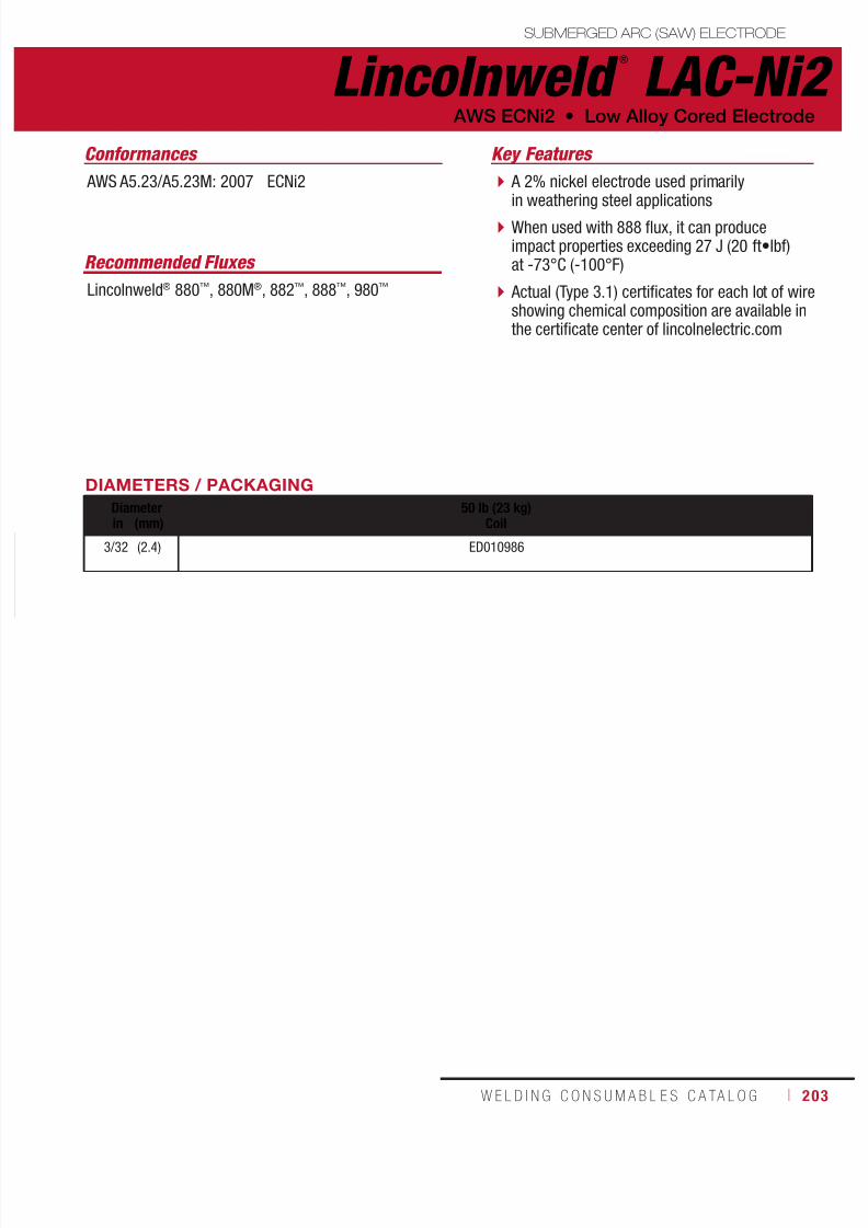
7/18/2019 c110 - Lincoln Electric Consumables 2014
http://slidepdf.com/reader/full/c110-lincoln-electric-consumables-2014 203/511W E L D I N G C O N S U M A B L E S C A TA L O G ı 203
SUBMERGED ARC (SAW) ELECTRODE
A 2% nickel electrode used primarilyin weathering steel applications
When used with 888 flux, it can produceimpact properties exceeding 27 J (20 ft•lbf)at -73°C (-100°F)
Actual (Type 3.1) certificates for each lot of wireshowing chemical composition are available inthe certificate center of lincolnelectric.com
AWS ECNi2 • Low Alloy Cored Electrode
Key Features
Recommended Fluxes
Lincolnweld® 880™, 880M®, 882™, 888™, 980™
Conformances
AWS A5.23/A5.23M: 2007 ECNi2
DIAMETERS / PACKAGING
Diameter 50 lb (23 kg)Coilin (mm)
3/32 (2.4) ED010986
Lincolnweld ®
LAC-Ni2
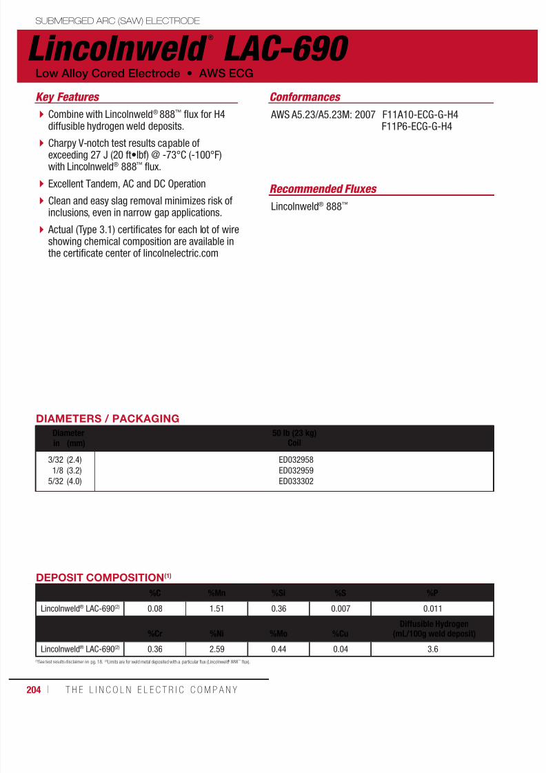
7/18/2019 c110 - Lincoln Electric Consumables 2014
http://slidepdf.com/reader/full/c110-lincoln-electric-consumables-2014 204/511204 ı T H E L I N C O L N E L E C T R I C C O M P A N Y
Lincolnweld ®
LAC-690 SUBMERGED ARC (SAW) ELECTRODE
Combine with Lincolnweld® 888™ flux for H4diffusible hydrogen weld deposits.
Charpy V-notch test results capable ofexceeding 27 J (20 ft•lbf) @ -73°C (-100°F)with Lincolnweld® 888™ flux.
Excellent Tandem, AC and DC Operation
Clean and easy slag removal minimizes risk ofinclusions, even in narrow gap applications.
Actual (Type 3.1) certificates for each lot of wireshowing chemical composition are available inthe certificate center of lincolnelectric.com
Low Alloy Cored Electrode • AWS ECG
Key Features
Recommended Fluxes
Lincolnweld® 888™
Conformances
AWS A5.23/A5.23M: 2007 F11A10-ECG-G-H4F11P6-ECG-G-H4
DIAMETERS / PACKAGING
Diameter 50 lb (23 kg)Coilin (mm)
3/32
1/8
5/32
(2.4)
(3.2)
(4.0)
ED032958
ED032959
ED033302
DEPOSIT COMPOSITION(1)
%C %Mn %Si %S %P
Lincolnweld® LAC-690(2) 0.08 1.51 0.36 0.007 0.011
%Cr %Ni %Mo %CuDiffusible Hydrogen
(mL/100g weld deposit)
Lincolnweld® LAC-690(2) 0.36 2.59 0.44 0.04 3.6
(1)See test results disclaimer on pg. 18. (2)Limits are for weld metal deposited with a particular flux (Lincolnweld® 888™ flux).
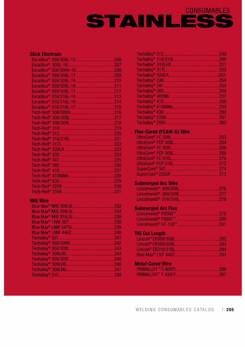
7/18/2019 c110 - Lincoln Electric Consumables 2014
http://slidepdf.com/reader/full/c110-lincoln-electric-consumables-2014 205/511W E L D I N G C O N S U M A B L E S C A TA L O G ı 205
CONSUMABLES
Stick Electrode
Excalibur® 308/308L-15 ................................206Excalibur® 308L-16........................................207Excalibur® 308/308H-16 ................................208Excalibur® 308/308L-17 ................................209Excalibur® 309/309L-15 ................................210Excalibur® 309/309L-16 ................................211Excalibur® 309/309L-17 ................................212Excalibur® 316/316L-15 ................................213Excalibur® 316/316L-16 ................................214Excalibur® 316/316L-17 ................................215Tech-Rod® 308/308H ..................................... 216
Tech-Rod®
308/308L .....................................217Tech-Rod® 309/309L .....................................218Tech-Rod® 310 ..............................................219Tech-Rod® 312 ..............................................220Tech-Rod® 316/316L .....................................221Tech-Rod® 317L ............................................222Tech-Rod® 320LR ..........................................223Tech-Rod® 330 ..............................................224Tech-Rod® 347 ..............................................225Tech-Rod® 385 ..............................................226Tech-Rod® 410 ..............................................227
Tech-Rod
®
410NiMo ......................................228Tech-Rod® 630 ..............................................229Tech-Rod® 2209 ............................................230Tech-Rod® 2594 ............................................231
MIG WireBlue Max® MIG 308LSi ................................... 232Blue Max® MIG 309LSi ................................... 234Blue Max® MIG 316LSi ................................... 236Blue Max® LNM 307.......................................238Blue Max® LNM 347Si .................................... 239Blue Max® LNM 4462.....................................240
Techalloy® 307 ............................................... 241Techalloy® 308/308H .....................................242Techalloy® 308/308L ...................................... 243Techalloy® 308LHS ........................................244Techalloy® 309/309L ...................................... 245Techalloy® 309LHS ........................................246Techalloy® 309LMo ........................................247Techalloy® 310 ............................................... 248
STAINLESS
Techalloy® 312 ............................................... 249
Techalloy® 316/316L ...................................... 250Techalloy® 316LHS ........................................251Techalloy® 317L ............................................. 252Techalloy® 320LR...........................................253Techalloy® 330 ............................................... 254Techalloy® 347 ............................................... 255Techalloy® 385 ............................................... 256Techalloy® 409Nb ..........................................257Techalloy® 410 ............................................... 258Techalloy® 410NiMo ....................................... 259Techalloy® 630 ............................................... 260
Techalloy®
2209 ............................................. 261Techalloy® 2594 ............................................. 262
Flux-Cored (FCAW-G) WireUltraCore® FC 308L ........................................ 263UltraCore® FCP 308L ...................................... 264UltraCore® FC 309L ........................................ 266UltraCore® FCP 309L ...................................... 268UltraCore® FC 316L ........................................ 270UltraCore® FCP 316L ...................................... 272SuperCore® 347 ............................................. 274SuperCore® 2205P ......................................... 275
Submerged Arc WireLincolnweld® 308/308L..................................276Lincolnweld® 309/309L..................................277Lincolnweld® 316/316L..................................278
Submerged Arc FluxLincolnweld® P2000™ ....................................279Lincolnweld® P2007™ ....................................280Lincolnweld® ST-100™ ................................... 281
TIG Cut LengthLincoln® ER308/308L ..................................... 282Lincoln® ER309/309L ..................................... 283Lincoln® ER316/316L ..................................... 284Blue Max® LNT 4462......................................285
Metal-Cored WirePRIMALLOY™ T-409Ti ..................................... 286PRIMALLOY™ T-439Ti ..................................... 287
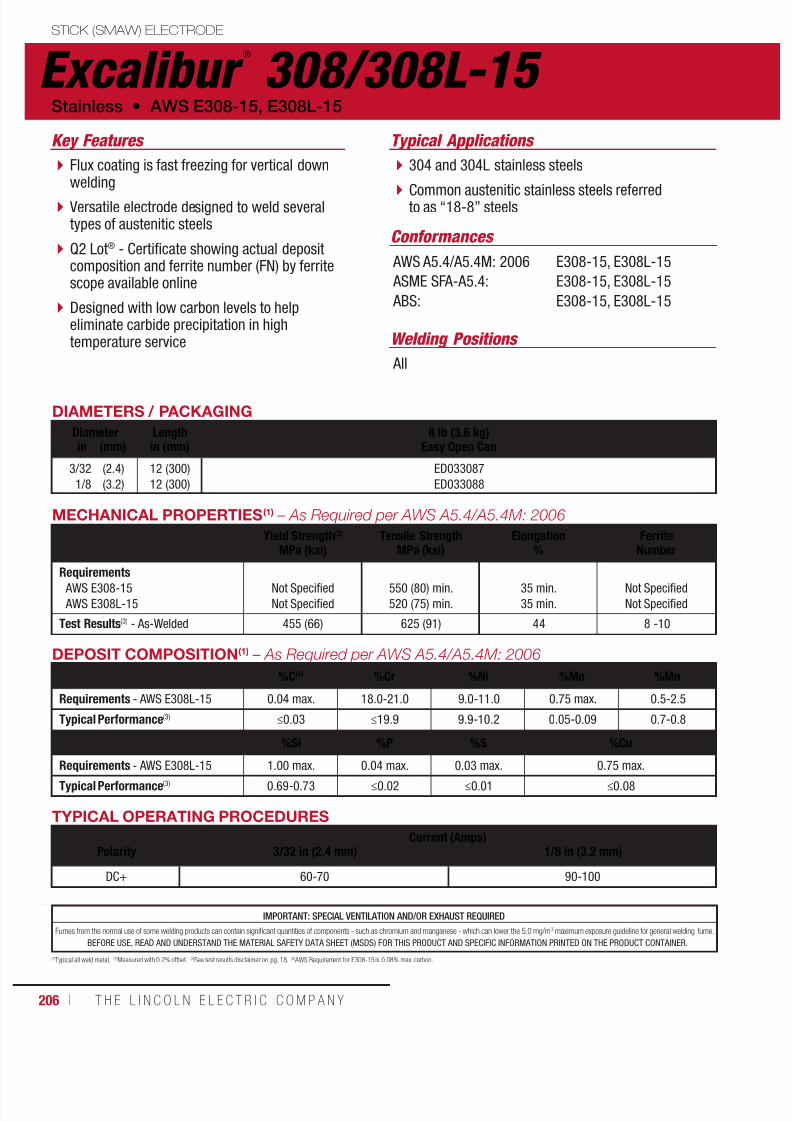
7/18/2019 c110 - Lincoln Electric Consumables 2014
http://slidepdf.com/reader/full/c110-lincoln-electric-consumables-2014 206/511206 ı T H E L I N C O L N E L E C T R I C C O M P A N Y
Excalibur ®
308/308L-15 STICK (SMAW) ELECTRODE
Welding Positions
Typical Applications
All
304 and 304L stainless steels
Common austenitic stainless steels referredto as “18-8” steels
Flux coating is fast freezing for vertical downwelding
Versatile electrode designed to weld severaltypes of austenitic steels
Q2 Lot® - Certificate showing actual depositcomposition and ferrite number (FN) by ferritescope available online
Designed with low carbon levels to helpeliminate carbide precipitation in hightemperature service
Conformances
Stainless • AWS E308-15, E308L-15
Key Features
AWS A5.4/A5.4M: 2006
ASME SFA-A5.4:
ABS:
E308-15, E308L-15
E308-15, E308L-15
E308-15, E308L-15
DIAMETERS / PACKAGING
Diameter Length 8 lb (3.6 kg)Easy Open Canin (mm) in (mm)
3/32
1/8
(2.4)
(3.2)
12 (300)
12 (300)
ED033087
ED033088
MECHANICAL PROPERTIES(1) – As Required per AWS A5.4/A5.4M: 2006
Yield Strength(2)
MPa (ksi)Tensile Strength
MPa (ksi)Elongation
%Ferrite
Number
Requirements AWS E308-15
AWS E308L-15
Not Specified
Not Specified
550 (80) min.
520 (75) min.
35 min.
35 min.
Not Specified
Not Specified
Test Results(3) - As-Welded 455 (66) 625 (91) 44 8 -10
DEPOSIT COMPOSITION(1) – As Required per AWS A5.4/A5.4M: 2006
%C(4) %Cr %Ni %Mo %Mn
Requirements - AWS E308L-15 0.04 max. 18.0-21.0 9.0-11.0 0.75 max. 0.5-2.5
Typical Performance(3) ≤0.03 ≤19.9 9.9-10.2 0.05-0.09 0.7-0.8
%Si %P %S %Cu
Requirements - AWS E308L-15 1.00 max. 0.04 max. 0.03 max. 0.75 max.Typical Performance(3) 0.69-0.73 ≤0.02 ≤0.01 ≤0.08
TYPICAL OPERATING PROCEDURES
Current (Amps)Polarity 3/32 in (2.4 mm) 1/8 in (3.2 mm)
DC+ 60-70 90-100
(1)Typical all weld metal. (2)Measured with 0.2% offset. (3)See test results disclaimer on pg. 18. (4) AWS Requirement for E308-15 is 0.08% max. carbon.
IMPORTANT: SPECIAL VENTILATION AND/OR EXHAUST REQUIRED
Fumes from the normal use of some welding products can contain significant quantities of components - such as chromium and manganese - which can lower the 5.0 mg/m3 maximum exposure guideline for general welding fume.
BEFORE USE, READ AND UNDERSTAND THE MATERIAL SAFETY DATA SHEET (MSDS) FOR THIS PRODUCT AND SPECIFIC INFORMATION PRINTED ON THE PRODUCT CONTAINER.

7/18/2019 c110 - Lincoln Electric Consumables 2014
http://slidepdf.com/reader/full/c110-lincoln-electric-consumables-2014 207/511W E L D I N G C O N S U M A B L E S C A TA L O G ı 207
Excalibur ®
308L-16STICK (SMAW) ELECTRODE
Welding Positions
Typical Applications
All, except vertical down
Type 302, 304 and 308 stainless steels
A743 and A744 Type CF-8 cast material
Flux coating provides smooth arc transfer inall welding positions, except vertical down
Versatile electrode designed to weld severaltypes of austenitic stainless steels
Q2 Lot® - Certificate showing actual depositcomposition and ferrite number (FN) by ferritescope available online
Designed with low carbon levels to helpeliminate carbide precipitation in hightemperature service
Conformances
AWS E308L-16 • Stainless
Key Features
AWS A5.4/A5.4M: 2006
ASME SFA-A5.4:
ABS:
CWB/CSA W48-06:
MIL-E-22200/2:
E308L-16
E308L-16
E308L-16
E308L-16
MIL-308L-16
DIAMETERS / PACKAGING
Diameter Length 8 lb (3.6 kg)Easy Open Can
10 lb (4.5 kg)Easy Open Canin (mm) in (mm)
3/32
1/8
5/32
3/16
(2.4)
(3.2)
(4.0)
(4.8)
12 (300)
14 (350)
14 (350)
14 (350)
ED033079
ED033080
ED033081
ED033082
MECHANICAL PROPERTIES(1) – As Required per AWS A5.4/A5.4M: 2006
Yield Strength(2)
MPa (ksi)
Tensile Strength
MPa (ksi)
Elongation
%
Ferrite
NumberRequirements - AWS E308L-16 Not Specified 520 (75) min. 35 min. Not Specified
Typical Performance(3) - As-Welded 370-420 (54-61) 540-595 (78-86) 50-55 8-9
TYPICAL OPERATING PROCEDURES
Current (Amps)Polarity(5) 3/32 in (2.4 mm) 1/8 in (3.2 mm) 5/32 in (4.0 mm) 3/16 in (4.8 mm)
DC+ 40-70 60-100 90-140 120-185
AC 40-70 60-100 90-140 120-185
(1)Typical all weld metal. (2)Measured with 0.2% offset. (3)See test results disclaimer on pg. 18. (4) AWS Requirement for E308-16 is 0.08% max. carbon. (5)Preferred polarity is listed first.
DEPOSIT COMPOSITION(1) – As Required per AWS A5.4/A5.4M: 2006
%C(4) %Cr %Ni %Mo %Mn
Requirements - AWS E308L-16 0.04-0.08(4) 18.0-21.0 9.0-11.0 0.75 max. 0.5-2.5
Typical Performance(3) 0.02-0.03 19.5-19.8 9.7-10.3 0.04-0.13 0.6-0.9
%Si %P %S %Cu
Requirements - AWS E308L-16 1.00 max. 0.04 max. 0.03 max. 0.75 max.
Typical Performance(3) 0.29-0.36 ≤0.03 ≤0.02 ≤0.10
IMPORTANT: SPECIAL VENTILATION AND/OR EXHAUST REQUIRED
Fumes from the normal use of some welding products can contain significant quantities of components - such as chromium and manganese - which can lower the 5.0 mg/m3 maximum exposure guideline for general welding fume.
BEFORE USE, READ AND UNDERSTAND THE MATERIAL SAFETY DATA SHEET (MSDS) FOR THIS PRODUCT AND SPECIFIC INFORMATION PRINTED ON THE PRODUCT CONTAINER.
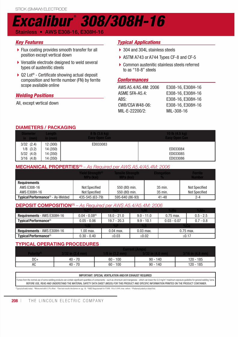
7/18/2019 c110 - Lincoln Electric Consumables 2014
http://slidepdf.com/reader/full/c110-lincoln-electric-consumables-2014 208/511208 ı T H E L I N C O L N E L E C T R I C C O M P A N Y
DIAMETERS / PACKAGING
Diameter Length 8 lb (3.6 kg)Easy Open Can
10 lb (4.5 kg)Easy Open Canin (mm) in (mm)
3/32
1/8
5/32
3/16
(2.4)
(3.2)
(4.0)
(4.8)
12 (300)
14 (350)
14 (350)
14 (350)
ED033083
ED033084
ED033085
ED033086
MECHANICAL PROPERTIES(1) – As Required per AWS A5.4/A5.4M: 2006
Yield Strength(2)
MPa (ksi)Tensile Strength
MPa (ksi)Elongation
%Ferrite
Number
Requirements AWS E308-16
AWS E308H-16
Not Specified
Not Specified
550 (80) min.
550 (80) min.
35 min.
35 min.
Not Specified
Not Specified
Typical Performance(3) - As-Welded 435-545 (63-79) 595-640 (86-93) 41-48 2-4
TYPICAL OPERATING PROCEDURESCurrent (Amps)
Polarity(5) 3/32 in (2.4 mm) 1/8 in (3.2 mm) 5/32 in (4.0 mm) 3/16 in (4.8 mm)
DC+ 40 - 70 60 - 100 90 - 140 120 - 185
AC 40 - 70 60 - 100 90 - 140 120 - 185
(1Typical all weld metal. (2)Measured with 0.2% offset. (3)See test results disclaimer on pg. 18. (4) AWS Requirement for E308L-16 is 0.04% max. carbon. (5)Preferred polarity is listed first.
DEPOSIT COMPOSITION(1) – As Required per AWS A5.4/A5.4M: 2006%C(4) %Cr %Ni %Mo %Mn
Requirements - AWS E308H-16 0.04 - 0.08(4) 18.0 - 21.0 9.0 - 11.0 0.75 max. 0.5 - 2.5
Typical Performance(3) 0.05 - 0.06 19.7 - 20.3 9.9 - 10.1 0.03 - 0.07 0.7 - 0.8
%Si %P %S %Cu
Requirements - AWS E308H-16 1.00 max. 0.04 max. 0.03 max. 0.75 max.Typical Performance(3) 0.30 - 0.40 ≤0.03 ≤0.02 ≤0.17
IMPORTANT: SPECIAL VENTILATION AND/OR EXHAUST REQUIRED
Fumes from the normal use of some welding products can contain significant quantities of components - such as chromium and manganese - which can lower the 5.0 mg/m3 maximum exposure guideline for general welding fume.
BEFORE USE, READ AND UNDERSTAND THE MATERIAL SAFETY DATA SHEET (MSDS) FOR THIS PRODUCT AND SPECIFIC INFORMATION PRINTED ON THE PRODUCT CONTAINER.
Excalibur ®
308/308H-16 STICK (SMAW) ELECTRODE
Welding Positions
Typical Applications
All, except vertical down
304 and 304L stainless steels
ASTM A743 or A744 Types CF-8 and CF-5 Common austenitic stainless steels referredto as “18-8” steels
Flux coating provides smooth transfer for allposition except vertical down
Versatile electrode designed to weld severaltypes of austenitic steels
Q2 Lot® - Certificate showing actual depositcomposition and ferrite number (FN) by ferritescope available online
Conformances
Stainless • AWS E308-16, E308H-16
Key Features
AWS A5.4/A5.4M: 2006
ASME SFA-A5.4:
ABS:
CWB/CSA W48-06:
MIL-E-22200/2:
E308-16, E308H-16
E308-16, E308H-16
E308-16, E308H-16
E308-16, E308H-16
MIL-308-16
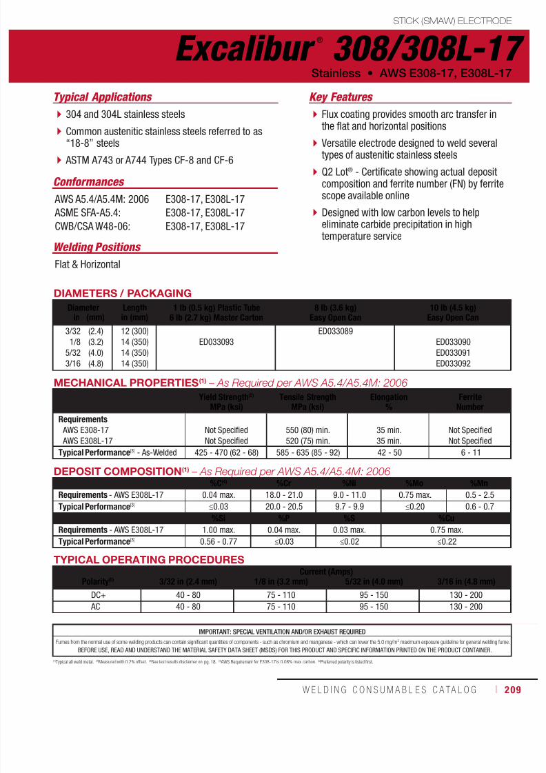
7/18/2019 c110 - Lincoln Electric Consumables 2014
http://slidepdf.com/reader/full/c110-lincoln-electric-consumables-2014 209/511W E L D I N G C O N S U M A B L E S C A TA L O G ı 209
Excalibur ®
308/308L-17STICK (SMAW) ELECTRODE
Welding Positions
Typical Applications
Flat & Horizontal
304 and 304L stainless steels
Common austenitic stainless steels referred to as“18-8” steels
ASTM A743 or A744 Types CF-8 and CF-6
Flux coating provides smooth arc transfer inthe flat and horizontal positions
Versatile electrode designed to weld severaltypes of austenitic stainless steels
Q2 Lot® - Certificate showing actual depositcomposition and ferrite number (FN) by ferritescope available online
Designed with low carbon levels to helpeliminate carbide precipitation in hightemperature service
Conformances
Stainless • AWS E308-17, E308L-17
Key Features
AWS A5.4/A5.4M: 2006
ASME SFA-A5.4:
CWB/CSA W48-06:
E308-17, E308L-17
E308-17, E308L-17
E308-17, E308L-17
DIAMETERS / PACKAGING
Diameter Length 1 lb (0.5 kg) Plastic Tube6 lb (2.7 kg) Master Carton
8 lb (3.6 kg)Easy Open Can
10 lb (4.5 kg)Easy Open Canin (mm) in (mm)
3/32
1/8
5/32
3/16
(2.4)
(3.2)
(4.0)
(4.8)
12 (300)
14 (350)
14 (350)
14 (350)
ED033093
ED033089
ED033090
ED033091
ED033092
MECHANICAL PROPERTIES(1) – As Required per AWS A5.4/A5.4M: 2006
Yield Strength(2)
MPa (ksi)Tensile Strength
MPa (ksi)Elongation
%Ferrite
Number
Requirements AWS E308-17
AWS E308L-17
Not Specified
Not Specified
550 (80) min.
520 (75) min.
35 min.
35 min.
Not Specified
Not Specified
Typical Performance(3) - As-Welded 425 - 470 (62 - 68) 585 - 635 (85 - 92) 42 - 50 6 - 11
DEPOSIT COMPOSITION(1) – As Required per AWS A5.4/A5.4M: 2006%C(4) %Cr %Ni %Mo %Mn
Requirements - AWS E308L-17 0.04 max. 18.0 - 21.0 9.0 - 11.0 0.75 max. 0.5 - 2.5
Typical Performance(3) ≤0.03 20.0 - 20.5 9.7 - 9.9 ≤0.20 0.6 - 0.7
%Si %P %S %Cu
Requirements - AWS E308L-17 1.00 max. 0.04 max. 0.03 max. 0.75 max.Typical Performance(3) 0.56 - 0.77 ≤0.03 ≤0.02 ≤0.22
TYPICAL OPERATING PROCEDURESCurrent (Amps)
Polarity(5) 3/32 in (2.4 mm) 1/8 in (3.2 mm) 5/32 in (4.0 mm) 3/16 in (4.8 mm)
DC+ 40 - 80 75 - 110 95 - 150 130 - 200
AC 40 - 80 75 - 110 95 - 150 130 - 200
(1)Typical all weld metal. (2)Measured with 0.2% offset. (3)See test results disclaimer on pg. 18. (4) AWS Requirement for E308-17 is 0.08% max. carbon. (5)Preferred polarity is listed first.
IMPORTANT: SPECIAL VENTILATION AND/OR EXHAUST REQUIRED
Fumes from the normal use of some welding products can contain significant quantities of components - such as chromium and manganese - which can lower the 5.0 mg/m3 maximum exposure guideline for general welding fume.
BEFORE USE, READ AND UNDERSTAND THE MATERIAL SAFETY DATA SHEET (MSDS) FOR THIS PRODUCT AND SPECIFIC INFORMATION PRINTED ON THE PRODUCT CONTAINER.

7/18/2019 c110 - Lincoln Electric Consumables 2014
http://slidepdf.com/reader/full/c110-lincoln-electric-consumables-2014 210/511210 ı T H E L I N C O L N E L E C T R I C C O M P A N Y
Excalibur ®
309/309L-15 STICK (SMAW) ELECTRODE
Welding Positions
Typical Applications
All
Joining stainless steel to mild or low alloy steel
ASTM A240 Type 309S
Flux coating is fast freezing for vertical downwelding
Designed for joining stainless steel to mild orlow alloy steel.
Q2 Lot® - Certificate showing actual depositcomposition and ferrite number (FN) by ferritescope available online
Designed with low carbon levels to helpeliminate carbide precipitation in hightemperature service
Conformances
AWS E309-15, E309L-15 • Stainless
Key Features
AWS A5.4/A5.4M: 2006:
ASME SFA-A5.4:
ABS:
E309-15, E309L-15
E309-15, E309L-15
E309-15, E309L-15
DIAMETERS / PACKAGING
Diameter Length 8 lb (3.6 kg)Easy Open Canin (mm) in (mm)
3/32
1/8
(2.4)
(3.2)
12 (300)
12 (300)
ED033098
ED033099
MECHANICAL PROPERTIES(1) – As Required per AWS A5.4/A5.4M: 2006
Yield Strength(2)
MPa (ksi)Tensile Strength
MPa (ksi)Elongation
%Ferrite
Number
Requirements AWS E309-15
AWS E309L-15
Not Specified
Not Specified
550 (80) min.
520 (75) min.
30 min.
30 min.
Not Specified
Not Specified
Test Results(3) - As-Welded 490 (71) 640 (93) 38 6-8
DEPOSIT COMPOSITION(1)
%C(4) %Cr %Ni %Mo %Mn
Requirements - AWS E309L-15 0.04 max. 22.0-25.0 12.0-14.0 0.75 max. 0.5-2.5
Typical Performance(3) ≤0.03 23.6-23.9 13.6-13.8 0.03-0.05 0.7-1.0
%Si %P %S %Cu
Requirements - AWS E309L-15 1.00 max. 0.04 max. 0.03 max. 0.75 max.Typical Performance(3) 0.74-0.82 ≤0.02 ≤0.01 ≤0.06
TYPICAL OPERATING PROCEDURES
Current (Amps)Polarity(5) 3/32 in (2.4 mm) 1/8 in (3.2 mm)
DC+ 60-70 90-100
(1)Typical all weld metal. (2)Measured with 0.2% offset. (3)See test results disclaimer on pg. 18. (4) AWS Requirement for E309-15 is 0.15% max. carbon. (5)Preferred polarity is listed first.
IMPORTANT: SPECIAL VENTILATION AND/OR EXHAUST REQUIRED
Fumes from the normal use of some welding products can contain significant quantities of components - such as chromium and manganese - which can lower the 5.0 mg/m3 maximum exposure guideline for general welding fume.
BEFORE USE, READ AND UNDERSTAND THE MATERIAL SAFETY DATA SHEET (MSDS) FOR THIS PRODUCT AND SPECIFIC INFORMATION PRINTED ON THE PRODUCT CONTAINER.
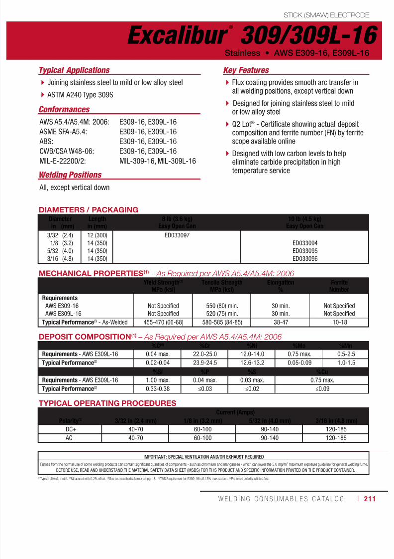
7/18/2019 c110 - Lincoln Electric Consumables 2014
http://slidepdf.com/reader/full/c110-lincoln-electric-consumables-2014 211/511W E L D I N G C O N S U M A B L E S C A TA L O G ı 211
Excalibur ®
309/309L-16STICK (SMAW) ELECTRODE
Welding Positions
Typical Applications
All, except vertical down
Joining stainless steel to mild or low alloy steel
ASTM A240 Type 309S
Flux coating provides smooth arc transfer inall welding positions, except vertical down
Designed for joining stainless steel to mildor low alloy steel
Q2 Lot® - Certificate showing actual depositcomposition and ferrite number (FN) by ferritescope available online
Designed with low carbon levels to helpeliminate carbide precipitation in hightemperature service
Conformances
Stainless • AWS E309-16, E309L-16
Key Features
AWS A5.4/A5.4M: 2006:
ASME SFA-A5.4:
ABS:
CWB/CSA W48-06:
MIL-E-22200/2:
E309-16, E309L-16
E309-16, E309L-16
E309-16, E309L-16
E309-16, E309L-16
MIL-309-16, MIL-309L-16
DIAMETERS / PACKAGINGDiameter Length 8 lb (3.6 kg)
Easy Open Can10 lb (4.5 kg)
Easy Open Canin (mm) in (mm)
3/32
1/8
5/32
3/16
(2.4)
(3.2)
(4.0)
(4.8)
12 (300)
14 (350)
14 (350)
14 (350)
ED033097
ED033094
ED033095
ED033096
MECHANICAL PROPERTIES(1) – As Required per AWS A5.4/A5.4M: 2006Yield Strength(2)
MPa (ksi)Tensile Strength
MPa (ksi)Elongation
%Ferrite
NumberRequirements AWS E309-16
AWS E309L-16
Not Specified
Not Specified
550 (80) min.
520 (75) min.
30 min.
30 min.
Not Specified
Not Specified
Typical Performance(3) - As-Welded 455-470 (66-68) 580-585 (84-85) 38-47 10-18
DEPOSIT COMPOSITION(1) – As Required per AWS A5.4/A5.4M: 2006%C(4) %Cr %Ni %Mo %Mn
Requirements - AWS E309L-16 0.04 max. 22.0-25.0 12.0-14.0 0.75 max. 0.5-2.5
Typical Performance(3) 0.02-0.04 23.9-24.5 12.6-13.2 0.05-0.09 1.0-1.5
%Si %P %S %Cu
Requirements - AWS E309L-16 1.00 max. 0.04 max. 0.03 max. 0.75 max.Typical Performance(3) 0.33-0.38 ≤0.03 ≤0.02 ≤0.09
TYPICAL OPERATING PROCEDURESCurrent (Amps)
Polarity(5) 3/32 in (2.4 mm) 1/8 in (3.2 mm) 5/32 in (4.0 mm) 3/16 in (4.8 mm)DC+ 40-70 60-100 90-140 120-185
AC 40-70 60-100 90-140 120-185
(1)Typical all weld metal. (2)Measured with 0.2% offset. (3)See test results disclaimer on pg. 18. (4) AWS Requirement for E309-16 is 0.15% max. carbon. (5)Preferred polarity is listed first.
IMPORTANT: SPECIAL VENTILATION AND/OR EXHAUST REQUIRED
Fumes from the normal use of some welding products can contain significant quantities of components - such as chromium and manganese - which can lower the 5.0 mg/m3 maximum exposure guideline for general welding fume.
BEFORE USE, READ AND UNDERSTAND THE MATERIAL SAFETY DATA SHEET (MSDS) FOR THIS PRODUCT AND SPECIFIC INFORMATION PRINTED ON THE PRODUCT CONTAINER.

7/18/2019 c110 - Lincoln Electric Consumables 2014
http://slidepdf.com/reader/full/c110-lincoln-electric-consumables-2014 212/511212 ı T H E L I N C O L N E L E C T R I C C O M P A N Y
Excalibur ®
309/309L-17 STICK (SMAW) ELECTRODE
Welding Positions
Typical Applications
Flat & Horizontal
Joining stainless steel to mild or low alloy steel
ASTM A240 Type 309S
Flux coating provides for smooth arc transferin the flat and horizontal positions
Designed for joining stainless steel to mild orlow alloy steel
Q2 Lot® - Certificate showing actual depositcomposition and ferrite number (FN) by ferritescope available online
Designed with low carbon levels to helpeliminate carbide precipitation in hightemperature service
Conformances
AWS E309-17, E309L-17 • Stainless
Key Features
AWS A5.4/A5.4M: 2006:
ASME SFA-A5.4:
ABS:
CWB/CSA W48-06:
E309-17, E309L-17
E309-17, E309L-17
E309-17, E309L-17
E309-17, E309L-17
DIAMETERS / PACKAGING
Diameter Length 8 lb (3.6 kg)Easy Open Can
10 lb (4.5 kg)Easy Open Canin (mm) in (mm)
3/32
1/8
5/32
3/16
(2.4)
(3.2)
(4.0)
(4.8)
12 (300)
14 (350)
14 (350)
14 (350)
ED033100
ED033101
ED033102
ED033103
MECHANICAL PROPERTIES(1) – As Required per AWS A5.4/A5.4M: 2006
Yield Strength(2)
MPa (ksi)Tensile Strength
MPa (ksi)Elongation
%Ferrite
Number
Requirements AWS E309-17
AWS E309L-17
Not Specified
Not Specified
550 (80) min.
520 (75) min.
30 min.
30 min.
Not Specified
Not Specified
Typical Performance(3) - As-Welded 455-490 (66-71) 585-620 (85-90) 37-45 7-11
DEPOSIT COMPOSITION(1) – As Required per AWS A5.4/A5.4M: 2006%C(4) %Cr %Ni %Mo %Mn
Requirements - AWS E309L-17 0.04 max. 22.0-25.0 12.0-14.0 0.75 max. 0.5-2.5
Typical Performance(3) 0.02-0.04 23.5-24.0 13.0-13.5 0.05-0.09 0.7-0.9
%Si %P %S %Cu
Requirements - AWS E309L-17 1.00 max. 0.04 max. 0.03 max. 0.75 max.
Typical Performance(3) 0.72-0.77 ≤0.03 ≤0.01 ≤0.17
TYPICAL OPERATING PROCEDURES
Current (Amps)Polarity(5) 3/32 in (2.4 mm) 1/8 in (3.2 mm) 5/32 in (4.0 mm) 3/16 in (4.8 mm)
DC+ 40-80 75-110 95-150 130-200
AC 40-80 75-110 95-150 130-200
(1)Typical all weld metal. (2)Measured with 0.2% offset. (3)See test results disclaimer on pg. 18. (4) AWS Requirement for E309-17 is 0.15% max. carbon. (5)Preferred polarity is listed first.
IMPORTANT: SPECIAL VENTILATION AND/OR EXHAUST REQUIRED
Fumes from the normal use of some welding products can contain significant quantities of components - such as chromium and manganese - which can lower the 5.0 mg/m3 maximum exposure guideline for general welding fume.
BEFORE USE, READ AND UNDERSTAND THE MATERIAL SAFETY DATA SHEET (MSDS) FOR THIS PRODUCT AND SPECIFIC INFORMATION PRINTED ON THE PRODUCT CONTAINER.

7/18/2019 c110 - Lincoln Electric Consumables 2014
http://slidepdf.com/reader/full/c110-lincoln-electric-consumables-2014 213/511W E L D I N G C O N S U M A B L E S C A TA L O G ı 213
Excalibur ®
316/316L-15STICK (SMAW) ELECTRODE
Welding Positions
Typical Applications
All
Molybdenum bearing austenitic stainless steels
Type 316 and 316L
Flux coating is fast freezing for verticaldown welding
Molybdenum grade for increased corrosionresistance
Q2 Lot® - Certificate showing actual depositcomposition and ferrite number (FN) by ferritescope available online
Designed with low carbon levels to helpeliminate carbide precipitation in hightemperature service
Conformances
Stainless • AWS E316-15, E316L-15
Key Features
AWS A5.4/A5.4M: 2006:
ASME SFA-A5.4:
ABS:
CWB/CSA W48-06:
E316-15, E316L-15
E316-15, E316L-15
E316-15, E316L-15
E316-15, E316L-15
DIAMETERS / PACKAGING
Diameter Length 8 lb (3.6 kg)Easy Open Canin (mm) in (mm)
3/32
1/8
(2.4)
(3.2)
12 (300)
12 (300)
ED033108
ED033109
MECHANICAL PROPERTIES(1) – As Required per AWS A5.4/A5.4M: 2006
Yield Strength(2)
MPa (ksi)Tensile Strength
MPa (ksi)Elongation
%Ferrite
Number
Requirements AWS E316-15
AWS E316L-15
Not Specified
Not Specified
520 (75) min.
490 (70) min.
30 min.
30 min.
Not Specified
Not Specified
Test Results(3) - As-Welded 470 (68) 620 (90) 38 4 - 12
DEPOSIT COMPOSITION(1) – As Required per AWS A5.4/A5.4M: 2006
%C(4) %Cr %Ni %Mo %Mn
Requirements - AWS E316L-15 0.04 max. 17.0-20.0 11.0-14.0 2.0-3.0 0.05-2.5
Typical Performance(3) ≤0.02 18.6-19.3 12.0-12.4 2.2-2.6 ≤0.7
%Si %P %S %Cu
Requirements - AWS E316L-15 1.00 max. 0.04 max. 0.03 max. 0.75 max.Typical Performance(3) 0.72-0.74 ≤0.02 ≤0.01 ≤0.24
TYPICAL OPERATING PROCEDURES
Current (Amps)Polarity 3/32 in (2.4 mm) 1/8 in (3.2 mm)
DC+ 60-70 90-100
(1)Typical all weld metal. (2)Measured with 0.2% offset. (3)See test results disclaimer on pg. 18. (4) AWS Requirement for E316-15 is 0.08% max. carbon.
IMPORTANT: SPECIAL VENTILATION AND/OR EXHAUST REQUIRED
Fumes from the normal use of some welding products can contain significant quantities of components - such as chromium and manganese - which can lower the 5.0 mg/m3 maximum exposure guideline for general welding fume.
BEFORE USE, READ AND UNDERSTAND THE MATERIAL SAFETY DATA SHEET (MSDS) FOR THIS PRODUCT AND SPECIFIC INFORMATION PRINTED ON THE PRODUCT CONTAINER.
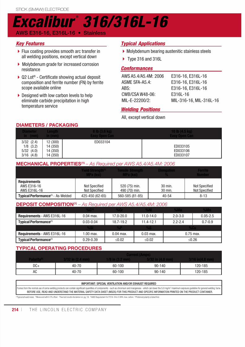
7/18/2019 c110 - Lincoln Electric Consumables 2014
http://slidepdf.com/reader/full/c110-lincoln-electric-consumables-2014 214/511214 ı T H E L I N C O L N E L E C T R I C C O M P A N Y
Excalibur ®
316/316L-16 STICK (SMAW) ELECTRODE
Welding Positions
Typical Applications
All, except vertical down
Molybdenum bearing austenitic stainless steels
Type 316 and 316L
Flux coating provides smooth arc transfer inall welding positions, except vertical down
Molybdenum grade for increased corrosionresistance
Q2 Lot® - Certificate showing actual depositcomposition and ferrite number (FN) by ferritescope available online
Designed with low carbon levels to helpeliminate carbide precipitation in hightemperature service
Conformances
AWS E316-16, E316L-16 • Stainless
Key Features
AWS A5.4/A5.4M: 2006
ASME SFA-A5.4:
ABS:
CWB/CSA W48-06:
MIL-E-22200/2:
E316-16, E316L-16
E316-16, E316L-16
E316-16, E316L-16
E316L-16
MIL-316-16, MIL-316L-16
DIAMETERS / PACKAGING
Diameter Length 8 lb (3.6 kg)Easy Open Can
10 lb (4.5 kg)Easy Open Canin (mm) in (mm)
3/321/8
5/323/16
(2.4)(3.2)(4.0)(4.8)
12 (300)14 (350)14 (350)14 (350)
ED033104ED033105ED033106ED033107
MECHANICAL PROPERTIES(1) – As Required per AWS A5.4/A5.4M: 2006
Yield Strength(2)
MPa (ksi)Tensile Strength
MPa (ksi)Elongation
%Ferrite
Number
Requirements AWS E316-16 AWS E316L-16
Not SpecifiedNot Specified
520 (75) min.490 (70) min.
30 min.30 min.
Not SpecifiedNot Specified
Typical Performance(3) - As-Welded 425-450 (62-65) 560-585 (81-85) 40-54 8-13
DEPOSIT COMPOSITION(1) – As Required per AWS A5.4/A5.4M: 2006%C(4) %Cr %Ni %Mo %Mn
Requirements - AWS E316L-16 0.04 max. 17.0-20.0 11.0-14.0 2.0-3.0 0.05-2.5
Typical Performance(3) 0.03-0.04 18.7-19.2 11.4-12.1 2.2-2.4 0.7-0.9
%Si %P %S %Cu
Requirements - AWS E316L-16 1.00 max. 0.04 max. 0.03 max. 0.75 max.
Typical Performance(3) 0.29-0.39 ≤0.02 ≤0.02 ≤0.26
TYPICAL OPERATING PROCEDURES
Current (Amps)Polarity(5) 3/32 in (2.4 mm) 1/8 in (3.2 mm) 5/32 in (4.0 mm) 3/16 in(4.8 mm)
DC+ 40-70 60-100 90-140 120-185
AC 40-70 60-100 90-140 120-185
(1)Typical all weld metal. (2)Measured with 0.2% offset. (3)See test results disclaimer on pg. 18. (4) AWS Requirement for E316-16 is 0.08% max. carbon. (5)Preferred polarity is listed first.
IMPORTANT: SPECIAL VENTILATION AND/OR EXHAUST REQUIRED
Fumes from the normal use of some welding products can contain significant quantities of components - such as chromium and manganese - which can lower the 5.0 mg/m3 maximum exposure guideline for general welding fume.
BEFORE USE, READ AND UNDERSTAND THE MATERIAL SAFETY DATA SHEET (MSDS) FOR THIS PRODUCT AND SPECIFIC INFORMATION PRINTED ON THE PRODUCT CONTAINER.
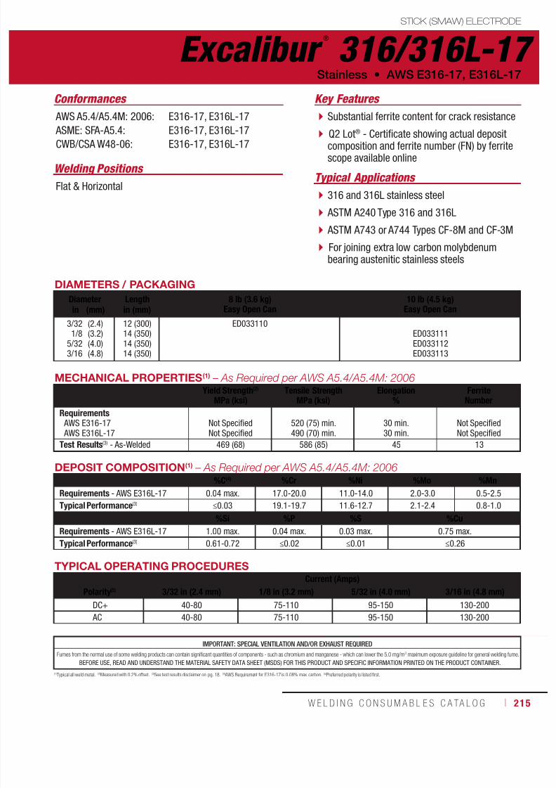
7/18/2019 c110 - Lincoln Electric Consumables 2014
http://slidepdf.com/reader/full/c110-lincoln-electric-consumables-2014 215/511W E L D I N G C O N S U M A B L E S C A TA L O G ı 215
IMPORTANT: SPECIAL VENTILATION AND/OR EXHAUST REQUIRED
Fumes from the normal use of some welding products can contain significant quantities of components - such as chromium and manganese - which can lower the 5.0 mg/m3 maximum exposure guideline for general welding fume.
BEFORE USE, READ AND UNDERSTAND THE MATERIAL SAFETY DATA SHEET (MSDS) FOR THIS PRODUCT AND SPECIFIC INFORMATION PRINTED ON THE PRODUCT CONTAINER.
Excalibur ®
316/316L-17STICK (SMAW) ELECTRODE
Welding Positions Typical Applications
Flat & Horizontal 316 and 316L stainless steel
ASTM A240 Type 316 and 316L
ASTM A743 or A744 Types CF-8M and CF-3M
For joining extra low carbon molybdenumbearing austenitic stainless steels
Substantial ferrite content for crack resistance
Q2 Lot® - Certificate showing actual depositcomposition and ferrite number (FN) by ferritescope available online
Conformances
Stainless • AWS E316-17, E316L-17
Key Features
AWS A5.4/A5.4M: 2006:
ASME: SFA-A5.4:CWB/CSA W48-06:
E316-17, E316L-17
E316-17, E316L-17E316-17, E316L-17
DIAMETERS / PACKAGING
Diameter Length 8 lb (3.6 kg)Easy Open Can
10 lb (4.5 kg)Easy Open Canin (mm) in (mm)
3/321/8
5/323/16
(2.4)(3.2)(4.0)(4.8)
12 (300)14 (350)14 (350)14 (350)
ED033110ED033111ED033112ED033113
MECHANICAL PROPERTIES(1) – As Required per AWS A5.4/A5.4M: 2006Yield Strength(2)
MPa (ksi)
Tensile Strength
MPa (ksi)
Elongation
%
Ferrite
NumberRequirements AWS E316-17 AWS E316L-17
Not SpecifiedNot Specified
520 (75) min.490 (70) min.
30 min.30 min.
Not SpecifiedNot Specified
Test Results(3) - As-Welded 469 (68) 586 (85) 45 13
DEPOSIT COMPOSITION(1) – As Required per AWS A5.4/A5.4M: 2006%C(4) %Cr %Ni %Mo %Mn
Requirements - AWS E316L-17 0.04 max. 17.0-20.0 11.0-14.0 2.0-3.0 0.5-2.5
Typical Performance(3) ≤0.03 19.1-19.7 11.6-12.7 2.1-2.4 0.8-1.0
%Si %P %S %Cu
Requirements - AWS E316L-17 1.00 max. 0.04 max. 0.03 max. 0.75 max.
Typical Performance(3) 0.61-0.72 ≤0.02 ≤0.01 ≤0.26
TYPICAL OPERATING PROCEDURESCurrent (Amps)
Polarity(5) 3/32 in (2.4 mm) 1/8 in (3.2 mm) 5/32 in (4.0 mm) 3/16 in (4.8 mm)
DC+ 40-80 75-110 95-150 130-200
AC 40-80 75-110 95-150 130-200
(1)Typical all weld metal. (2)Measured with 0.2% offset. (3)See test results disclaimer on pg. 18. (4) AWS Requirement for E316-17 is 0.08% max. carbon. (5)Preferred polarity is listed first.

7/18/2019 c110 - Lincoln Electric Consumables 2014
http://slidepdf.com/reader/full/c110-lincoln-electric-consumables-2014 216/511216 ı T H E L I N C O L N E L E C T R I C C O M P A N Y
Tech-Rod ®
308/308H STICK (SMAW) ELECTRODE
Stainless • AWS E308-16/308H-16
AWS A5.4/A5.4M: 2010: E308-16/308H-16
ASME SFA-A5.4: E308-16/308H-16
Conformances
Typical Applications
DIAMETERS / PACKAGINGDiameter Length
in (mm)8 lb (3.6 kg) Tube
24 lb (10.9 kg) Master Carton10 lb (4.5 kg) Tube
30 lb (13.6 kg) Master Cartonin (mm)
3/32
1/8
5/32
3/16
(2.4)
(3.2)
(4.0)
(4.8)
12 (305)
14 (355)
14 (355)
14 (355)
EL308H16093632
EL308H16125634
EL308H16156634
EL308H16187634
TYPICAL OPERATING PROCEDURESDiameterin (mm)
Lengthin (mm)
AmperageFlat Vertical & Overhead
3/32 (2.4) 12 (305) 70-85 65-75
1/8 (3.2) 14 (355) 85-110 80-90
5/32 (4.0) 14 (355) 110-140 100-120
3/16 (4.8) 14 (355) 120-160 110-130
DEPOSIT COMPOSITION(1) – As Required per AWS A5.4/A5.4M: 2010
%C %Cr %Ni %Mo %MnRequirements AWS 308H-16 0.04-0.08 18.0 - 21.0 9.0 - 11.0 0.75 max. 0.5 - 2.5
Typical Results(2)
Tech-Rod® 308/308H 0.05 19.7 9.9 0.16 1.5
%Si %P %S %Cu FN
Requirements AWS 308H-16 1.00 max. 0.04 max. 0.03 max. 0.75 max. Not Required
Typical Results(2)
Tech-Rod® 308/308H 0.53 0.02 0.01 0.11 4 - 9
(1)Typical all weld metal. (2)See test results disclaimer on pg. 18.Safety Data Sheets (SDS) are available on our website at www.techalloy.com
Used to weld unstabilized austenitic stainlesssteels such as 302, 304H and 305.
Provide a high carbon deposit (minimum of0.04% carbon) for high temperatureapplications.
Chemical Process & Petrochemical
Catalytic Crackers
Pulp and Paper
Key Features
NOTE: Nitrogen in these weld deposits is usually between 0.04% and 0.08%
Welding Positions
All, except vertical down
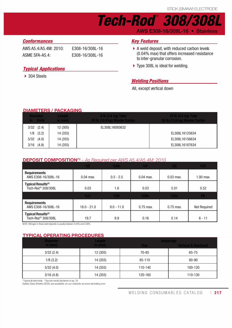
7/18/2019 c110 - Lincoln Electric Consumables 2014
http://slidepdf.com/reader/full/c110-lincoln-electric-consumables-2014 217/511W E L D I N G C O N S U M A B L E S C A TA L O G ı 217
Tech-Rod ®
308/308LSTICK (SMAW) ELECTRODE
AWS E308-16/308L-16 • Stainless
AWS A5.4/A5.4M: 2010: E308-16/308L-16
ASME SFA-A5.4: E308-16/308L-16
Conformances
DIAMETERS / PACKAGINGDiameter Lengthin (mm)
8 lb (3.6 kg) Tube24 lb (10.9 kg) Master Carton
10 lb (4.5 kg) Tube30 lb (13.6 kg) Master Cartonin (mm)
3/32
1/8
5/32
3/16
(2.4)
(3.2)
(4.0)
(4.8)
12 (305)
14 (355)
14 (355)
14 (355)
EL308L16093632
EL308L16125634
EL308L16156634
EL308L16187634
TYPICAL OPERATING PROCEDURESDiameterin (mm)
Lengthin (mm)
AmperageFlat Vertical & Overhead
3/32 (2.4) 12 (305) 70-85 65-75
1/8 (3.2) 14 (355) 85-110 80-90
5/32 (4.0) 14 (355) 110-140 100-120
3/16 (4.8) 14 (355) 120-160 110-130
DEPOSIT COMPOSITION(1) – As Required per AWS A5.4/A5.4M: 2010
%C %Mn %P %S %Si
Requirements AWS E308-16/308L-16 0.04 max. 0.5 - 2.5 0.04 max. 0.03 max. 1.00 max.
Typical Results(2)
Tech-Rod® 308/308L 0.03 1.6 0.03 0.01 0.52
%Cr %Ni %Mo %Cu FN
Requirements AWS E308-16/308L-16 18.0 - 21.0 9.0 - 11.0 0.75 max. 0.75 max. Not Required
Typical Results(2)
Tech-Rod® 308/308L 19.7 9.9 0.16 0.14 6 - 11
Typical Applications
(1)Typical all weld metal. (2)See test results disclaimer on pg. 18.Safety Data Sheets (SDS) are available on our website at www.techalloy.com
304 Steels
A weld deposit, with reduced carbon levels(0.04% max) that offers increased resistanceto inter-granular corrosion.
Type 308L is ideal for welding.
Key Features
NOTE: Nitrogen in these weld deposits is usually between 0.04% and 0.08%
Welding Positions
All, except vertical down
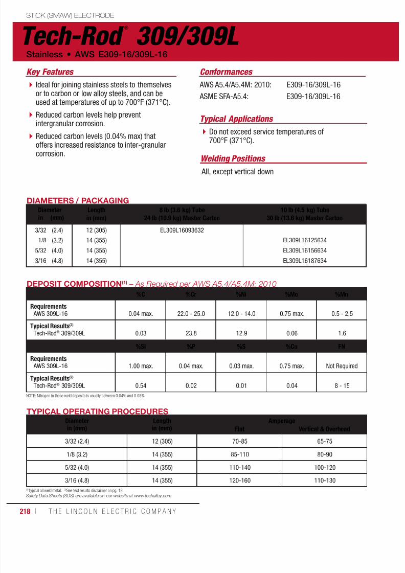
7/18/2019 c110 - Lincoln Electric Consumables 2014
http://slidepdf.com/reader/full/c110-lincoln-electric-consumables-2014 218/511218 ı T H E L I N C O L N E L E C T R I C C O M P A N Y
Tech-Rod ®
309/309L STICK (SMAW) ELECTRODE
Stainless • AWS E309-16/309L-16
AWS A5.4/A5.4M: 2010: E309-16/309L-16
ASME SFA-A5.4: E309-16/309L-16
DIAMETERS / PACKAGINGDiameter Length
in (mm)8 lb (3.6 kg) Tube
24 lb (10.9 kg) Master Carton10 lb (4.5 kg) Tube
30 lb (13.6 kg) Master Cartonin (mm)
3/32
1/8
5/32
3/16
(2.4)
(3.2)
(4.0)
(4.8)
12 (305)
14 (355)
14 (355)
14 (355)
EL309L16093632
EL309L16125634
EL309L16156634
EL309L16187634
TYPICAL OPERATING PROCEDURESDiameterin (mm)
Lengthin (mm)
AmperageFlat Vertical & Overhead
3/32 (2.4) 12 (305) 70-85 65-75
1/8 (3.2) 14 (355) 85-110 80-90
5/32 (4.0) 14 (355) 110-140 100-120
3/16 (4.8) 14 (355) 120-160 110-130
DEPOSIT COMPOSITION(1) – As Required per AWS A5.4/A5.4M: 2010
%C %Cr %Ni %Mo %Mn
Requirements AWS 309L-16 0.04 max. 22.0 - 25.0 12.0 - 14.0 0.75 max. 0.5 - 2.5
Typical Results(2)
Tech-Rod® 309/309L 0.03 23.8 12.9 0.06 1.6
%Si %P %S %Cu FN
Requirements AWS 309L-16 1.00 max. 0.04 max. 0.03 max. 0.75 max. Not Required
Typical Results(2)
Tech-Rod® 309/309L 0.54 0.02 0.01 0.04 8 - 15
NOTE: Nitrogen in these weld deposits is usually between 0.04% and 0.08%
Conformances
(1)Typical all weld metal. (2)See test results disclaimer on pg. 18.Safety Data Sheets (SDS) are available on our website at www.techalloy.com
Ideal for joining stainless steels to themselvesor to carbon or low alloy steels, and can beused at temperatures of up to 700°F (371°C).
Reduced carbon levels help preventintergranular corrosion.
Reduced carbon levels (0.04% max) thatoffers increased resistance to inter-granularcorrosion.
Do not exceed service temperatures of700°F (371°C).
Key Features
Typical Applications
Welding Positions
All, except vertical down

7/18/2019 c110 - Lincoln Electric Consumables 2014
http://slidepdf.com/reader/full/c110-lincoln-electric-consumables-2014 219/511W E L D I N G C O N S U M A B L E S C A TA L O G ı 219
Excalibur ®
310-16STICK (SMAW) ELECTRODE
AWS E310-16 • Stainless
AWS A5.4/A5.4M: 2010: E310-16
ASME SFA-A5.4: E310-16
DIAMETERS / PACKAGINGDiameter Length
in (mm)8 lb (3.6 kg) Easy Open Can
24 lb (10.9 kg) Master Carton10 lb (4.5 kg) Easy Open Can30 lb (13.6 kg) Master Cartonin (mm)
3/32
1/8
5/32
(2.4)
(3.2)
(4.0)
12 (305)
14 (355)
14 (355)
ED034993
ED034994
ED034995
TYPICAL OPERATING PROCEDURESDiameterin (mm)
Lengthin (mm)
AmperageFlat Vertical & Overhead
3/32 (2.4) 12 (305) 70-85 65-75
1/8 (3.2) 14 (355) 85-110 80-90
5/32 (4.0) 14 (355) 110-140 100-120
DEPOSIT COMPOSITION(1) – As Required per AWS A5.4/A5.4M: 2010
%C %Cr %Ni %Mo %Mn
Requirements AWS E310-16 0.08 - 0.20 25.0 - 28.0 20.0 - 22.5 0.75 max. 1.0 - 2.5
Typical Results(2) 0.11 25.5 21.0 0.1 2.0
%Si %P %S %Cu FN
Requirements AWS E310-16 0.75 max. 0.03 max. 0.03 max. 0.75 max. Not Required
Typical Results(2) 0.58 0.02 0.01 0.02 –
Conformances
(1)Typical all weld metal. (2)See test results disclaimer on pg. 18.Safety Data Sheets (SDS) are available on our website at www.techalloy.com
Used for welding stainless steels of similarcomposition in cast and wrought forms.
The weld deposit is fully austenitic, and as such,calls for minimal heat input during welding.
Head Shields
Furnace Parts
Ducting
Key Features
Typical Applications
NOTE: Nitrogen in these weld deposits is usually between 0.04% and 0.08%
Welding Positions
All, except vertical down
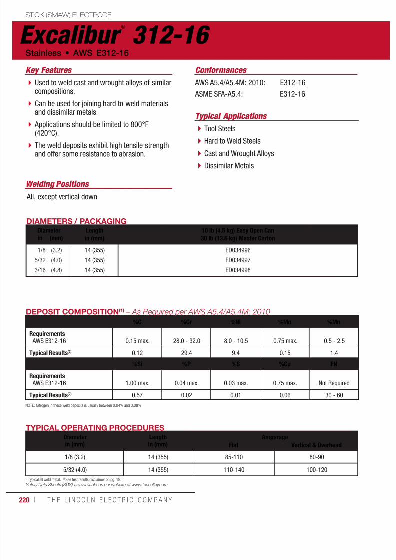
7/18/2019 c110 - Lincoln Electric Consumables 2014
http://slidepdf.com/reader/full/c110-lincoln-electric-consumables-2014 220/511220 ı T H E L I N C O L N E L E C T R I C C O M P A N Y
Excalibur ®
312-16 STICK (SMAW) ELECTRODE
Stainless • AWS E312-16
AWS A5.4/A5.4M: 2010: E312-16
ASME SFA-A5.4: E312-16
DIAMETERS / PACKAGINGDiameter Length
in (mm)10 lb (4.5 kg) Easy Open Can30 lb (13.6 kg) Master Cartonin (mm)
1/8
5/32
3/16
(3.2)
(4.0)
(4.8)
14 (355)
14 (355)
14 (355)
ED034996
ED034997
ED034998
TYPICAL OPERATING PROCEDURESDiameterin (mm)
Lengthin (mm)
AmperageFlat Vertical & Overhead
1/8 (3.2) 14 (355) 85-110 80-90
5/32 (4.0) 14 (355) 110-140 100-120
DEPOSIT COMPOSITION(1) – As Required per AWS A5.4/A5.4M: 2010
%C %Cr %Ni %Mo %Mn
Requirements AWS E312-16 0.15 max. 28.0 - 32.0 8.0 - 10.5 0.75 max. 0.5 - 2.5
Typical Results(2) 0.12 29.4 9.4 0.15 1.4
%Si %P %S %Cu FN
Requirements
AWS E312-16 1.00 max. 0.04 max. 0.03 max. 0.75 max. Not Required
Typical Results(2) 0.57 0.02 0.01 0.06 30 - 60
Conformances
Used to weld cast and wrought alloys of similarcompositions.
Can be used for joining hard to weld materialsand dissimilar metals.
Applications should be limited to 800°F(420°C).
The weld deposits exhibit high tensile strengthand offer some resistance to abrasion.
Tool Steels
Hard to Weld Steels
Cast and Wrought Alloys
Dissimilar Metals
Key Features
Typical Applications
(1)Typical all weld metal. (2)See test results disclaimer on pg. 18.Safety Data Sheets (SDS) are available on our website at www.techalloy.com
NOTE: Nitrogen in these weld deposits is usually between 0.04% and 0.08%
Welding Positions
All, except vertical down

7/18/2019 c110 - Lincoln Electric Consumables 2014
http://slidepdf.com/reader/full/c110-lincoln-electric-consumables-2014 221/511W E L D I N G C O N S U M A B L E S C A TA L O G ı 221
Tech-Rod ®
316/316LSTICK (SMAW) ELECTRODE
AWS E316-16/E316L-16 • Stainless
AWS A5.4/A5.4M: 2010: E316-16/E316L-16
ASME SFA-A5.4: E316-16/E316L-16
DIAMETERS / PACKAGINGDiameter Length
in (mm)8 lb (3.6 kg) Tube
24 lb (10.9 kg) Master Carton10 lb (4.5 kg) Tube
30 lb (13.6 kg) Master Cartonin (mm)
3/32
1/8
5/32
3/16
(2.4)
(3.2)
(4.0)
(4.8)
12 (305)
14 (355)
14 (355)
14 (355)
EL316L16093632
EL316L16125634
EL316L16156634
EL316L16187634
TYPICAL OPERATING PROCEDURESDiameterin (mm)
Lengthin (mm)
AmperageFlat Vertical & Overhead
3/32 (2.4) 12 (305) 70-85 65-75
1/8 (3.2) 14 (355) 85-110 80-90
5/32 (4.0) 14 (355) 110-140 100-120
3/16 (4.8) 14 (355) 120-160 110-130
DEPOSIT COMPOSITION(1) – As Required per AWS A5.4/A5.4M: 2010
%C %Cr %Ni %Mo %Mn
Requirements AWS E316L-16 0.04 max. 17.0 - 20.0 11.0 - 14.0 2.0 - 3.0 0.5 - 2.5
Typical Results(2) 0.02 18.4 12.3 2.4 1.5
%Si %P %S %Cu FN
Requirements AWS E316L-16 1.00 max. 0.04 max 0.03 max. 0.75 max. Not Required
Typical Results(2) 0.51 0.02 0.01 0.16 4 - 9
Conformances
Used for welding 316L base metals.
The 2-3% molybdenum in the electrodeimproves pitting corrosion resistance of theweld deposit.
Low carbon content reduces the possibilityof carbide precipitation and intergranularcorrosion.
Power Generation
Chemical and Petrochemical Processing
Key Features
Typical Applications
(1)Typical all weld metal. (2)See test results disclaimer on pg. 18.Safety Data Sheets (SDS) are available on our website at www.techalloy.com
NOTE: Nitrogen in these weld deposits is usually between 0.04% and 0.08%
Welding Positions
All, except vertical down

7/18/2019 c110 - Lincoln Electric Consumables 2014
http://slidepdf.com/reader/full/c110-lincoln-electric-consumables-2014 222/511222 ı T H E L I N C O L N E L E C T R I C C O M P A N Y
Tech-Rod ®
317L STICK (SMAW) ELECTRODE
Stainless • AWS E317L-16
AWS A5.4/A5.4M: 2010: E317L-16
ASME SFA-A5.4: E317L-16
DIAMETERS / PACKAGINGDiameter Length
in (mm)8 lb (3.6 kg) Tube
24 lb (10.9 kg) Master Carton10 lb (4.5 kg) Tube
30 lb (13.6 kg) Master Cartonin (mm)
3/32
1/8
5/32
(2.4)
(3.2)
(4.0)
12 (305)
14 (355)
14 (355)
EL317L16093632
EL317L16125634
EL317L16156634
TYPICAL OPERATING PROCEDURES
Diameterin (mm)
Lengthin (mm)
AmperageFlat Vertical & Overhead
3/32 (2.4) 12 (305) 70-85 65-75
1/8 (3.2) 14 (355) 85-110 80-90
5/32 (4.0) 14 (355) 110-140 100-120
DEPOSIT COMPOSITION(1) – As Required per AWS A5.4/A5.4M: 2010
%C %Cr %Ni %Mo %Mn
Requirements AWS E317L-16 0.04 max. 18.0 - 21.0 12.0 - 14.0 3.0 - 4.0 0.5 - 2.5
Typical Results(2)
Tech-Rod® 317L 0.02 19.7 13.1 3.6 1.4
%Si %P %S %Cu FN
Requirements AWS E317L-16 1.00 max. 0.04 max. 0.03 max. 0.75 max. Not Required
Typical Results(2)
Tech-Rod® 317L 0.48 0.02 0.01 0.15 4 - 9
Conformances
A weld deposit similar to 316L with a highermolybdenum content.
Electrodes are used for welding alloys withsimilar compositions used in highly corrosiveenvironments.
FGP
Chemical Processing Plants
Condensors
Petrochemical
Key Features
Typical Applications
(1)Typical all weld metal. (2)See test results disclaimer on pg. 18.Safety Data Sheets (SDS) are available on our website at www.techalloy.com
NOTE: Nitrogen in these weld deposits is usually between 0.04% and 0.08%
Welding Positions
All, except vertical down

7/18/2019 c110 - Lincoln Electric Consumables 2014
http://slidepdf.com/reader/full/c110-lincoln-electric-consumables-2014 223/511W E L D I N G C O N S U M A B L E S C A TA L O G ı 223
Excalibur ®
320LR-16STICK (SMAW) ELECTRODE
AWS E320LR-16 • Stainless
AWS A5.4/A5.4M: 2010: E320LR-16
ASME SFA-A5.4: E320LR-16
DIAMETERS / PACKAGINGDiameter Lengthin (mm)
8 lb (3.6 kg) Easy Open Can24 lb (10.9 kg) Master Carton
10 lb (4.5 kg) Easy Open Can30 lb (13.6 kg) Master Cartonin (mm)
3/32
1/8
5/32
3/16
(2.4)
(3.2)
(4.0)
(4.8)
12 (305)
14 (355)
14 (355)
14 (355)
ED034999
ED035000
ED035001
ED035002
TYPICAL OPERATING PROCEDURESDiameterin (mm)
Lengthin (mm)
AmperageFlat Vertical & Overhead
3/32 (2.4) 12 (305) 70-85 65-75
1/8 (3.2) 14 (355) 85-110 80-90
5/32 (4.0) 14 (355) 110-140 100-120
3/16 (4.8) 14 (355) 120-160 110-130
DEPOSIT COMPOSITION(1) – As Required per AWS A5.4/A5.4M: 2010
%C %Cr %Ni %Mo %Nb+Ta %MnRequirements AWS E320LR-16 0.03 max. 19.0 - 21.0 32.0 - 36.0 2.0 - 3.0 0.4 max. 1.50 - 2.50
Typical Results(2)
Tech-Rod® 320LR 0.02 19.9 33.8 2.3 0.1 1.70
%Si %P %S %Cu FN
Requirements AWS E320LR-16 0.30 max. 0.020 max. 0.015 max. 3.0 - 4.0 Not Required
Typical Results(2)
Tech-Rod® 320LR 0.16 0.016 0.006 3.2 –
Conformances
Are typically used for welding base metals withsimilar compositions including alloy 20.
Process Piping
Heat Exchangers
Chemical Processing Industry
Key Features
Typical Applications
(1)Typical all weld metal. (2)See test results disclaimer on pg. 18.Safety Data Sheets (SDS) are available on our website at www.techalloy.com
NOTE: Nitrogen in these weld deposits is usually between 0.04% and 0.08%
Welding Positions
All, except vertical down
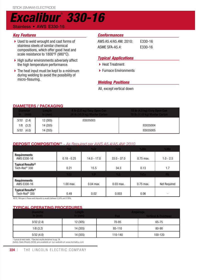
7/18/2019 c110 - Lincoln Electric Consumables 2014
http://slidepdf.com/reader/full/c110-lincoln-electric-consumables-2014 224/511224 ı T H E L I N C O L N E L E C T R I C C O M P A N Y
Excalibur ®
330-16 STICK (SMAW) ELECTRODE
Stainless • AWS E330-16
AWS A5.4/A5.4M: 2010: E330-16
ASME SFA-A5.4: E330-16
DIAMETERS / PACKAGINGDiameter Length
in (mm)8 lb (3.6 kg) Easy Open Can
24 lb (10.9 kg) Master Carton10 lb (4.5 kg) Easy Open Can30 lb (13.6 kg) Master Cartonin (mm)
3/32
1/8
5/32
(2.4)
(3.2)
(4.0)
12 (305)
14 (355)
14 (355)
ED035003
ED035004
ED035005
TYPICAL OPERATING PROCEDURESDiameterin (mm)
Lengthin (mm)
AmperageFlat Vertical & Overhead
3/32 (2.4) 12 (305) 70-85 65-75
1/8 (3.2) 14 (355) 85-110 80-90
5/32 (4.0) 14 (355) 110-140 100-120
DEPOSIT COMPOSITION(1) – As Required per AWS A5.4/A5.4M: 2010%C %Cr %Ni %Mo %Mn
Requirements AWS E330-16 0.18 - 0.25 14.0 - 17.0 33.0 - 37.0 0.75 max. 1.0 - 2.5
Typical Results(2)
Tech-Rod® 330 0.21 15.5 34.3 0.13 1.7
%Si %P %S %Cu FN
Requirements AWS E330-16 1.00 max. 0.04 max. 0.03 max. 0.75 max. Not Required
Typical Results(2)
Tech-Rod® 330 0.49 0.02 0.003 0.06 –
Conformances
Used to weld wrought and cast forms ofstainless steels of similar chemicalcompositions, which offer good heat andscale resistance to 1800°F (980°C).
High sulfur environments adversely affectthe high temperature performance.
The heat input must be kept to a minimumduring welding to avoid the possibility ofmicro-fissuring.
Heat Treatment
Furnace Environments
Key Features
Typical Applications
(1)Typical all weld metal. (2)See test results disclaimer on pg. 18.Safety Data Sheets (SDS) are available on our website at www.techalloy.com
NOTE: Nitrogen in these weld deposits is usually between 0.04% and 0.08%
Welding Positions
All, except vertical down

7/18/2019 c110 - Lincoln Electric Consumables 2014
http://slidepdf.com/reader/full/c110-lincoln-electric-consumables-2014 225/511W E L D I N G C O N S U M A B L E S C A TA L O G ı 225
Excalibur ®
347-16STICK (SMAW) ELECTRODE
AWS E347-16 • Stainless
AWS A5.4/A5.4M: 2010: E347-16
ASME SFA-A5.4: E347-16
DIAMETERS / PACKAGINGDiameter Length
in (mm)8 lb (3.6 kg) Easy Open Can
24 lb (10.9 kg) Master Carton10 lb (4.5 kg) Easy Open Can30 lb (13.6 kg) Master Cartonin (mm)
3/32
1/8
5/32
3/16
(2.4)
(3.2)
(4.0)
(4.8)
12 (305)
14 (355)
14 (355)
14 (355)
ED035006
ED035007
ED035008
ED035009
TYPICAL OPERATING PROCEDURESDiameterin (mm)
Lengthin (mm)
AmperageFlat Vertical & Overhead
3/32 (2.4) 12 (305) 70-85 65-75
1/8 (3.2) 14 (355) 85-110 80-90
5/32 (4.0) 14 (355) 110-140 100-120
3/16 (4.8) 14 (355) 120-160 110-130
DEPOSIT COMPOSITION(1) – As Required per AWS A5.4/A5.4M: 2010
%C %Cr %Ni %Mo %Nb+Ta %MnRequirements AWS E347-16 0.08 max. 18.0 - 21.0 9.0 - 11.0 0.75 max. 8 x C to 1.00 max. 0.5 - 2.5
Typical Results(2)
Tech-Rod® 347 0.03 19.5 10.1 0.19 0.36 1.5
%Si %P %S %Cu FN
Requirements AWS E347-16 1.00 max. 0.04 max. 0.03 max. 0.75 max. Not Required
Typical Results(2)
Tech-Rod® 347 0.54 0.02 0.01 0.16 5 - 10
Conformances
Niobium stabilized stainless steel electrodesused for the welding of types 347 and 321stainless and stainless clad steels.
The addition of niobium reduces intergranularcorrosion in severe operating conditions. Food Processing
Pharmaceutical Equipment
Key Features
Typical Applications
(1)Typical all weld metal. (2)See test results disclaimer on pg. 18.Safety Data Sheets (SDS) are available on our website at www.techalloy.com
NOTE: Nitrogen in these weld deposits is usually between 0.04% and 0.08%
Welding Positions
All, except vertical down

7/18/2019 c110 - Lincoln Electric Consumables 2014
http://slidepdf.com/reader/full/c110-lincoln-electric-consumables-2014 226/511226 ı T H E L I N C O L N E L E C T R I C C O M P A N Y
Excalibur ®
385-16 STICK (SMAW) ELECTRODE
Stainless • AWS E385-16
AWS A5.4/A5.4M: 2010: E385-16
ASME SFA A5.4: E385-16
DIAMETERS / PACKAGINGDiameter Length
in (mm)10 lb (4.5 kg) Easy Open Can30 lb (13.6 kg) Master Cartonin (mm)
1/8
5/32
(3.2)
(4.0)
14 (355)
14 (355)
ED035010
ED035011
TYPICAL OPERATING PROCEDURESDiameterin (mm)
Lengthin (mm)
AmperageFlat Vertical & Overhead
1/8 (3.2) 14 (355) 85-110 80-90
5/32 (4.0) 14 (355) 110-140 100-120
DEPOSIT COMPOSITION(1) – As Required per AWS A5.4/A5.4M: 2010
%C %Cr %Ni %Mo %Mn
Requirements AWS E385-16 0.03 max. 19.5 - 21.5 24.0 - 26.0 4.2 - 5.2 1.0 - 2.5
Typical Results(2) 0.02 20.4 24.9 4.8 1.4
%Si %P %S %Cu
Requirements AWS E385-16 0.90 max. 0.03 max. 0.02 max. 1.2 - 2.0
Typical Results(2) 0.34 0.01 0.01 1.6
Conformances
Used for welding materials of similar chemicalcomposition (type 904L).
Used in fabrication of equipment and vesselsfor handling and storage of sulfuric acid andphosphoric acid.
The weld metal is fully austenitic, and must bedone with low heat input, using a stringer beadtechnique.
Key Features
(1)Typical all weld metal. (2)See test results disclaimer on pg. 18.
Safety Data Sheets (SDS) are available on our website at www.techalloy.com
NOTE: Nitrogen in these weld deposits is usually between 0.04% and 0.08%
Welding Positions
All, except vertical down
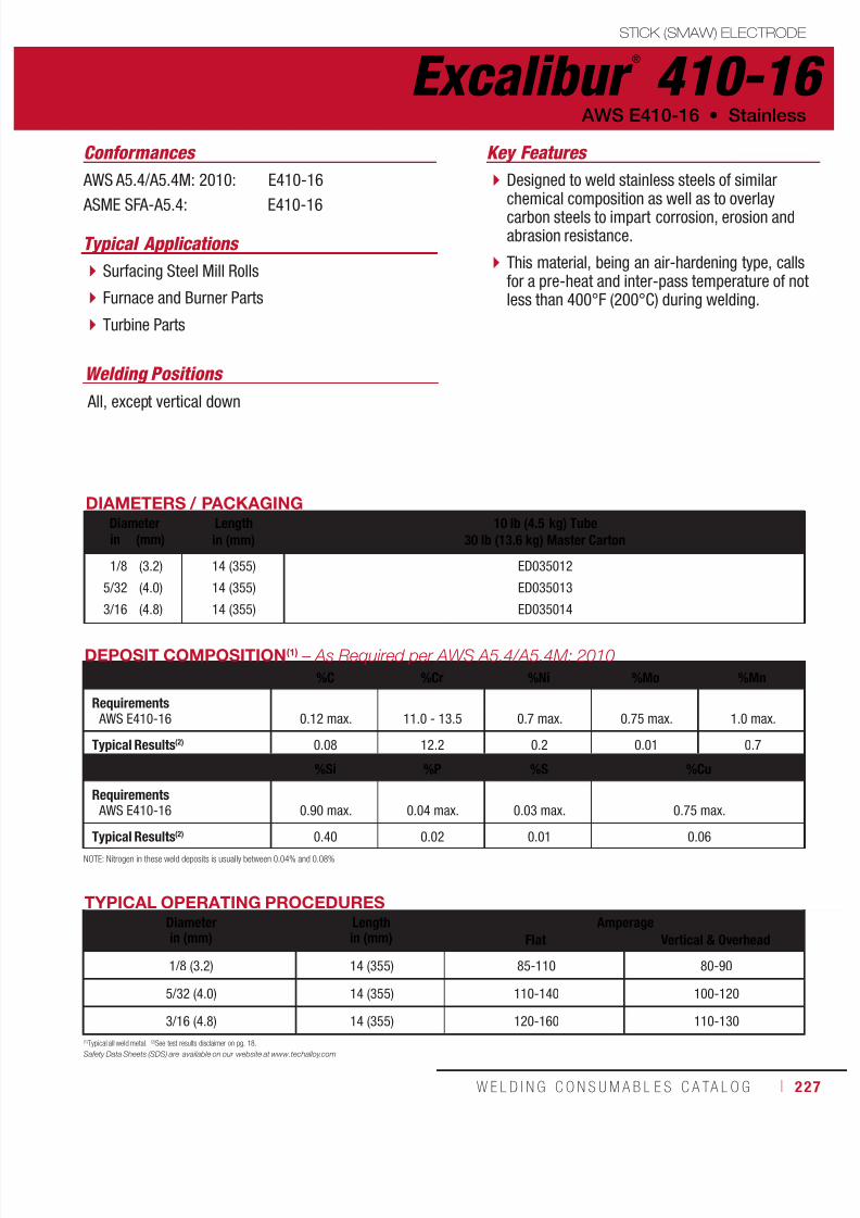
7/18/2019 c110 - Lincoln Electric Consumables 2014
http://slidepdf.com/reader/full/c110-lincoln-electric-consumables-2014 227/511W E L D I N G C O N S U M A B L E S C A TA L O G ı 227
Excalibur ®
410-16STICK (SMAW) ELECTRODE
AWS E410-16 • Stainless
AWS A5.4/A5.4M: 2010: E410-16
ASME SFA-A5.4: E410-16
DIAMETERS / PACKAGINGDiameter Length
in (mm)10 lb (4.5 kg) Tube
30 lb (13.6 kg) Master Cartonin (mm)
1/8
5/32
3/16
(3.2)
(4.0)
(4.8)
14 (355)
14 (355)
14 (355)
ED035012
ED035013
ED035014
TYPICAL OPERATING PROCEDURESDiameterin (mm)
Lengthin (mm)
AmperageFlat Vertical & Overhead
1/8 (3.2) 14 (355) 85-110 80-90
5/32 (4.0) 14 (355) 110-140 100-120
3/16 (4.8) 14 (355) 120-160 110-130
DEPOSIT COMPOSITION(1) – As Required per AWS A5.4/A5.4M: 2010
%C %Cr %Ni %Mo %Mn
Requirements AWS E410-16 0.12 max. 11.0 - 13.5 0.7 max. 0.75 max. 1.0 max.
Typical Results(2) 0.08 12.2 0.2 0.01 0.7
%Si %P %S %Cu
Requirements AWS E410-16 0.90 max. 0.04 max. 0.03 max. 0.75 max.
Typical Results(2) 0.40 0.02 0.01 0.06
Conformances
Designed to weld stainless steels of similarchemical composition as well as to overlaycarbon steels to impart corrosion, erosion andabrasion resistance.
This material, being an air-hardening type, callsfor a pre-heat and inter-pass temperature of notless than 400°F (200°C) during welding.
Surfacing Steel Mill Rolls
Furnace and Burner Parts
Turbine Parts
Key Features
Typical Applications
(1)Typical all weld metal. (2)See test results disclaimer on pg. 18.
Safety Data Sheets (SDS) are available on our website at www.techalloy.com
NOTE: Nitrogen in these weld deposits is usually between 0.04% and 0.08%
Welding Positions
All, except vertical down

7/18/2019 c110 - Lincoln Electric Consumables 2014
http://slidepdf.com/reader/full/c110-lincoln-electric-consumables-2014 228/511228 ı T H E L I N C O L N E L E C T R I C C O M P A N Y
Excalibur ®
410NiMo-16 STICK (SMAW) ELECTRODE
Stainless • AWS E410NiMo-16
AWS A5.4/A4.5M: 2010: E410NiMo-16
ASME SFA-A5.4: E410NiMo-16
DIAMETERS / PACKAGINGDiameter Length
in (mm)10 lb (4.5 kg) Easy Open Can30 lb (13.6 kg) Master Cartonin (mm)
1/8
5/32
3/16
(3.2)
(4.0)
(4.8)
14 (355)
14 (355)
14 (355)
ED035015
ED035016
ED035018
TYPICAL OPERATING PROCEDURESDiameterin (mm)
Lengthin (mm)
AmperageFlat Vertical & Overhead
1/8 (3.2) 14 (355) 85-110 80-90
5/32 (4.0) 14 (355) 110-140 100-120
3/16 (4.8) 14 (355) 120-160 110-130
DEPOSIT COMPOSITION(1) – As Required per AWS A5.4/A5.4M: 2010%C %Cr %Ni %Mo %Mn
Requirements AWS E410NiMo-16 0.06 max. 11.0 - 12.5 4.0 - 5.0 0.40 - 0.70 1.0 max.
Typical Results(2)
Tech-Rod® 410NiMo 0.02 11.7 4.6 0.58 0.5
%Si %P %S %Cu FN
Requirements AWS E410NiMo-16 0.90 max. 0.04 max. 0.03 max. 0.75 max. Not Required
Typical Results(2)
Tech-Rod® 410NiMo 0.37 0.02 0.01 0.07 –
Conformances
Designed to weld materials of similar chemicalcomposition in cast and wrought forms.
This electrode is also used to overlay mild andlow alloy steels.
Preheat and inter-pass temperatures of not lessthan 300°F (150°C) are recommended duringwelding.
Post-weld heat treatment should not exceed1150°F (620°C) as higher temperatures mayresult in hardening.
Turbines
Valve Bodies
High Pressure Piping
Offshore
Power Generation
Key Features
Typical Applications
(1)Typical all weld metal. (2)See test results disclaimer on pg. 18.Safety Data Sheets (SDS) are available on our website at www.techalloy.com
NOTE: Nitrogen in these weld deposits is usually between 0.04% and 0.08%
Welding Positions
All, except vertical down
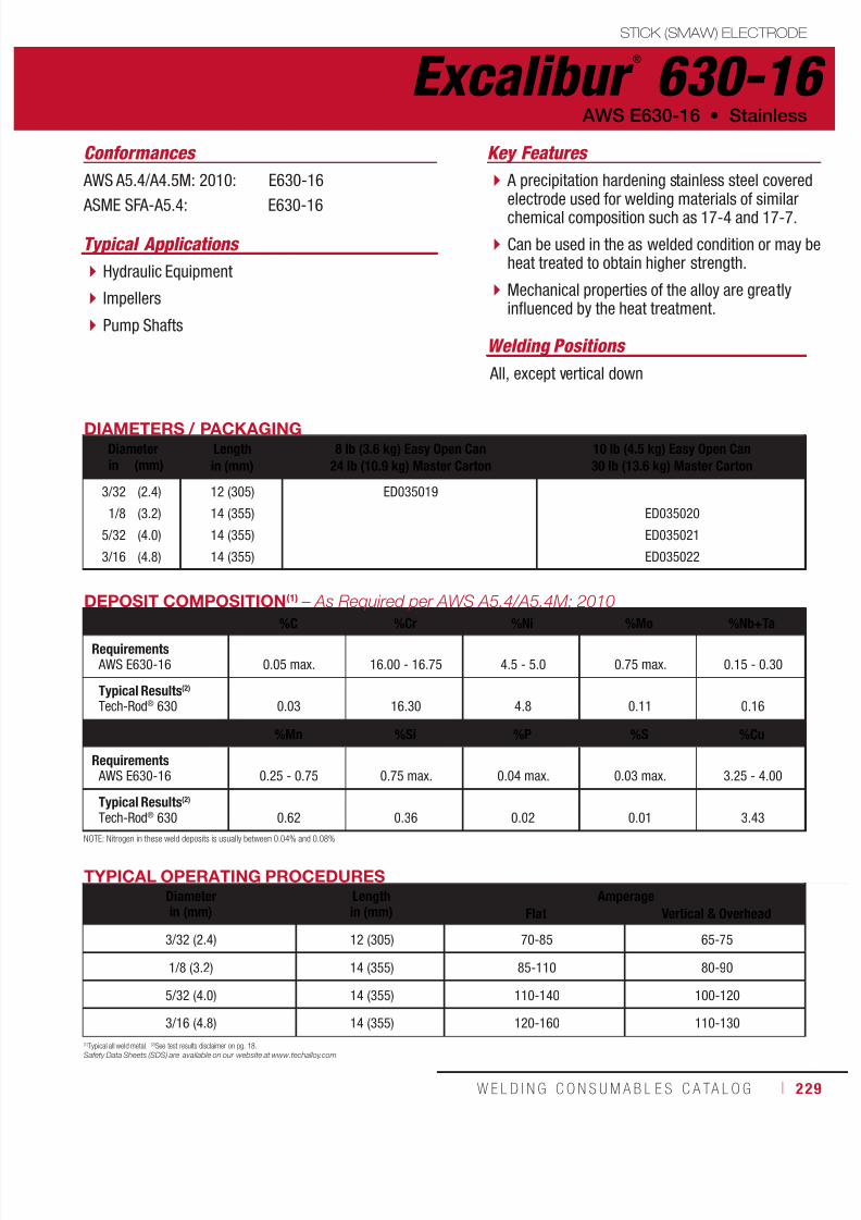
7/18/2019 c110 - Lincoln Electric Consumables 2014
http://slidepdf.com/reader/full/c110-lincoln-electric-consumables-2014 229/511W E L D I N G C O N S U M A B L E S C A TA L O G ı 229
Excalibur ®
630-16STICK (SMAW) ELECTRODE
AWS E630-16 • Stainless
AWS A5.4/A4.5M: 2010: E630-16
ASME SFA-A5.4: E630-16
DIAMETERS / PACKAGINGDiameter Length
in (mm)8 lb (3.6 kg) Easy Open Can
24 lb (10.9 kg) Master Carton10 lb (4.5 kg) Easy Open Can30 lb (13.6 kg) Master Cartonin (mm)
3/32
1/8
5/32
3/16
(2.4)
(3.2)
(4.0)
(4.8)
12 (305)
14 (355)
14 (355)
14 (355)
ED035019
ED035020
ED035021
ED035022
TYPICAL OPERATING PROCEDURESDiameterin (mm)
Lengthin (mm)
AmperageFlat Vertical & Overhead
3/32 (2.4) 12 (305) 70-85 65-75
1/8 (3.2) 14 (355) 85-110 80-90
5/32 (4.0) 14 (355) 110-140 100-120
3/16 (4.8) 14 (355) 120-160 110-130
DEPOSIT COMPOSITION(1) – As Required per AWS A5.4/A5.4M: 2010
%C %Cr %Ni %Mo %Nb+TaRequirements AWS E630-16 0.05 max. 16.00 - 16.75 4.5 - 5.0 0.75 max. 0.15 - 0.30
Typical Results(2)
Tech-Rod® 630 0.03 16.30 4.8 0.11 0.16
%Mn %Si %P %S %Cu
Requirements AWS E630-16 0.25 - 0.75 0.75 max. 0.04 max. 0.03 max. 3.25 - 4.00
Typical Results(2)
Tech-Rod® 630 0.62 0.36 0.02 0.01 3.43
Conformances
A precipitation hardening stainless steel coveredelectrode used for welding materials of similarchemical composition such as 17-4 and 17-7.
Can be used in the as welded condition or may beheat treated to obtain higher strength.
Mechanical properties of the alloy are greatlyinfluenced by the heat treatment.
Hydraulic Equipment
Impellers
Pump Shafts
Key Features
Typical Applications
(1)Typical all weld metal. (2)See test results disclaimer on pg. 18.Safety Data Sheets (SDS) are available on our website at www.techalloy.com
NOTE: Nitrogen in these weld deposits is usually between 0.04% and 0.08%
Welding Positions
All, except vertical down

7/18/2019 c110 - Lincoln Electric Consumables 2014
http://slidepdf.com/reader/full/c110-lincoln-electric-consumables-2014 230/511230 ı T H E L I N C O L N E L E C T R I C C O M P A N Y
Excalibur ®
2209-16 STICK (SMAW) ELECTRODE
Stainless • AWS E2209-16
AWS A5.4/A4.5M: 2010: E2209-16
ASME SFA-A5.4: E2209-16
DIAMETERS / PACKAGINGDiameter Length
in (mm)8 lb (3.6 kg) Easy Open Can
24 lb (10.9 kg) Master Carton10 lb (4.5 kg) Easy Open Can30 lb (13.6 kg) Master Cartonin (mm)
3/32
1/8
5/32
3/16
(2.4)
(3.2)
(4.0)
(4.8)
12 (305)
14 (355)
14 (355)
14 (355)
ED034985
ED034986
ED034987
ED034988
TYPICAL OPERATING PROCEDURESDiameterin (mm)
Lengthin (mm)
AmperageFlat Vertical & Overhead
3/32 (2.4) 12 (305) 70-85 65-75
1/8 (3.2) 14 (355) 85-110 80-90
5/32 (4.0) 14 (355) 110-140 100-120
3/16 (4.8) 14 (355) 120-160 110-130
DEPOSIT COMPOSITION(1) – As Required per AWS A5.4/A5.4M: 2010
%C %Cr %Ni %Mo %Mn %Si
Requirements AWS E2209-16 0.04 max. 21.5 - 23.5 8.5 - 10.5 2.5 - 3.5 0.5 - 2.0 1.0 max.
Typical Results(2)
Tech-Rod® 2209 0.02 22.3 9.5 3.2 1.1 0.5
%P %S %N %Cu FN
Requirements AWS E2209-16 0.04 max. 0.03 max. 0.08 - 0.20 0.75 max. Not Required
Typical Results(2)
Tech-Rod®
2209 0.02 0.01 0.16 0.06 30 - 60
Conformances
Used to weld duplex stainless steels such as(Type 2205).
The welds offer excellent resistance to stresscorrosion, cracking and pitting.
The microstructure of the weld metal consists ofaustenite and ferrite.
The ferrite content of the weld metal will be lowerthan the ferrite content of type 2205 base metal.
Welding of duplex stainless steels calls forcontrolled welding parameters to achieve specifiedmechanical and corrosion resistant properties.
Offshore
Oil and Gas
Chemical
Petrochemical
Key Features
Typical Applications
(1)Typical all weld metal. (2)See test results disclaimer on pg. 18.
Safety Data Sheets (SDS) are available on our website at www.techalloy.com
NOTE: Nitrogen in these weld deposits is usually between 0.04% and 0.08%
Welding Positions
All, except vertical down

7/18/2019 c110 - Lincoln Electric Consumables 2014
http://slidepdf.com/reader/full/c110-lincoln-electric-consumables-2014 231/511W E L D I N G C O N S U M A B L E S C A TA L O G ı 231
Excalibur ®
2594-16STICK (SMAW) ELECTRODE
AWS E2594-16 • Stainless
AWS A5.4/A4.5M: 2010: E2594-16
ASME SFA-A5.4: E2594-16
DIAMETERS / PACKAGINGDiameter Length
in (mm)8 lb (3.6 kg) Easy Open Can
24 lb (10.9 kg) Master Carton10 lb (4.5 kg) Easy Open Can30 lb (13.6 kg) Master Cartonin (mm)
3/32
1/8
5/32
3/16
(2.4)
(3.2)
(4.0)
(4.8)
12 (305)
14 (355)
14 (355)
14 (355)
ED034989
ED034990
ED034991
ED034992
TYPICAL OPERATING PROCEDURESDiameterin (mm)
Lengthin (mm)
AmperageFlat Vertical & Overhead
3/32 (2.4) 12 (305) 70-85 65-75
1/8 (3.2) 14 (355) 85-110 80-90
5/32 (4.0) 14 (355) 110-140 100-120
3/16 (4.8) 14 (355) 120-160 110-130
DEPOSIT COMPOSITION(1) – As Required per AWS A5.4/A5.4M: 2010%C %Cr %Ni %Mo %Mn %Si
Requirements AWS E2594-16 0.04 max. 24.0 - 27.0 8.0 - 10.5 3.5 - 4.5 0.5 - 2.0 1.00 max.
Typical Results(2)
Tech-Rod® 2594 0.02 25.4 9.2 4.2 0.8 0.58
%P %S %N %Cu FN
Requirements AWS E2594-16 0.04 max. 0.03 max. 0.20 - 0.30 0.75 max. Not Required
Typical Results(2)
Tech-Rod® 2594 0.01 0.01 0.22 0.07 30 - 60
Conformances
A super-duplex grade electrode that providesmatching chemistry and mechanical propertycharacteristics to wrought super-duplex alloyssuch as 2507 and Zeron 100, as well as tosuper-duplex casting alloys (ATSM A890).
The electrode is over-alloyed 2-3% in nickel toprovide the optimum ferrite/austenite ratio in thefinished weld.
This structure results in high tensile and yieldstrengths and superior resistance to stresscorrosion cracking (SCC) and pitting corrosion.
Process Pipework
Pumps and Valves
Pressure Vessels
Key Features
Typical Applications
(1)Typical all weld metal. (2)See test results disclaimer on pg. 18.
Safety Data Sheets (SDS) are available on our website at www.techalloy.com
NOTE: Nitrogen in these weld deposits is usually between 0.04% and 0.08%
Welding Positions
All, except vertical down

7/18/2019 c110 - Lincoln Electric Consumables 2014
http://slidepdf.com/reader/full/c110-lincoln-electric-consumables-2014 232/511232 ı T H E L I N C O L N E L E C T R I C C O M P A N Y
Blue Max ®
MIG 308LSi MIG (GMAW) WIRE
Welding Positions
Typical Applications
All
304 and 304L stainless steels
Common austenitic stainless steels referredto as “18-8” steels
ASTM A743 or A744 Types CF-8 and CF-3
High silicon level for increased puddle fluidityand toe wetting
Proprietary surface lubricant for steadyfeeding and arc stability
Versatile electrode designed to weld CrNiaustenitic stainless steels
Q2 Lot® - Certificate showing actual wirecomposition and calculated ferrite number(FN) available online
Controlled ferrite content for maximumcorrosion resistance
Conformances
Shielding Gas
Short Circuiting Transfer:90% Helium / 7-1/2% Argon / 2-1/2% CO
2
Axial Spray Transfer:98% Argon / Balance Oxygen
Stainless • AWS ER308Si, ER308LSi
Key Features
AWS A5.9/A5.9M: 2006:
ASME SFA-A5.9: ABS:
CWB/CSA W48-06:
EN ISO 14343-B:
ER308Si, ER308LSi
ER308Si, ER308LSiER308Si, ER308LSi
ER308LSi
SS308LSi
DIAMETERS / PACKAGING
Diameter 25 lb (11.3 kg)Plastic Spool
500 lb (227 kg)Accu-Trak® Drum
1000 lb (454 kg)Precise-Trak™ Reelin (mm)
0.030
0.0350.045
1/16
(0.8)
(0.9)(1.1)
(1.6)
ED023961
ED019292ED019293
ED019294
ED029768ED029769
ED032834
MECHANICAL PROPERTIES(1) – As Required per AWS A5.9/A5.9M: 2006
Yield Strength(2)
MPa (ksi)Tensile Strength
MPa (ksi)Elongation
%Ferrite
Number
Requirements - AWS ER308Si, ER308LSi Not Specified
Test Results(3) - As-Welded 455 (66) 635 (92) 46 13

7/18/2019 c110 - Lincoln Electric Consumables 2014
http://slidepdf.com/reader/full/c110-lincoln-electric-consumables-2014 233/511W E L D I N G C O N S U M A B L E S C A TA L O G ı 233
Blue Max ®
MIG 308LSi
MIG (GMAW) WIRE
(AWS ER308Si, ER308LSi)
(1)Typical all weld metal. (2)See test results disclaimer on pg. 18. (3) AWS Requirement for ER308Si is 0.08% max. carbon. (4)Included in 0.50% max. for other elements not specified. (5)To estimate ESO, subtract 1/8 in (3 mm) from CTWD.
TYPICAL OPERATING PROCEDURES
Diameter, Polarity
Shielding Gas
CTWD(5)
mm (in)
Wire Feed Speed Voltage
(Volts)
Approx. Current
(Amps)
Deposition Rate
m/min (in/min) kg/hr (lb/hr)Short Circuit Transfer
0.035 in (0.9 mm), DC+
90% He / 7-1/2% Ar / 2-1/2% CO2
13 (1/2)
13 (1/2)
13 (1/2)
13 (1/2)
13 (1/2)
13 (1/2)
3.0
4.6
5.8
7.6
8.9
10.2
(120)
(180)
(230)
(300)
(350)
(400)
19-20
19-20
20-21
20-21
21-22
22-23
55
85
105
125
140
160
0.9
1.4
1.8
2.3
2.7
3.1
(2.0)
(3.0)
(3.9)
(5.0)
(5.9)
(6.7)
0.045 in (1.1 mm), DC+
90% He / 7-1/2% Ar / 2-1/2% CO2
13 (1/2)
13 (1/2)
13 (1/2)
13 (1/2)
13 (1/2)
13 (1/2)
13 (1/2)
2.5
3.2
3.8
4.4
5.6
6.4
7.0
(100)
(125)
(150)
(175)
(220)
(250)
(275)
19-20
19-20
21
21
22
22-23
22-23
100
120
135
140
170
175
185
1.1
1.5
1.7
2.0
2.6
2.9
3.2
(2.8)
(3.5)
(4.2)
(4.8)
(6.1)
(6.9)
(7.6)
Axial Spray Transfer
0.035 in (0.9 mm), DC+
98% Ar/2% O2
13 (1/2)
13 (1/2)
13 (1/2)
13 (1/2)
10.2
10.8
11.4
12.1
(400)
(425)
(450)
(475)
22
23
23
23
180
190
200
210
3.1
3.3
3.5
3.7
(6.7)
(7.1)
(7.5)
(8.0)
0.045 in (1.1 mm), DC+
98% Ar/2% O2
13 (1/2)
13 (1/2)
13 (1/2)
13 (1/2)13 (1/2)
6.1
6.6
7.6
8.39.1
(240)
(260)
(300)
(325)(360)
23
24
24
2525
195
230
240
250260
2.8
3.0
3.5
3.84.2
(6.6)
(7.2)
(8.3)
(9.0)(10.0)
1/16 in (1.6 mm), DC+
98% Ar/2% O2
19 (3/4)
19 (3/4)
19 (3/4)
19 (3/4)
19 (3/4)
4.4
5.1
6.4
7.0
7.6
(175)
(200)
(250)
(275)
(300)
25
26
26
27
28
260
310
330
360
390
4.3
4.9
6.2
6.8
7.4
(9.2)
(10.5)
(13.1)
(14.4)
(15.8)
WIRE COMPOSITION(1) – As Required per AWS A5.9/A5.9M: 2006
%C(3) %Cr %Ni %Mo %Mn
Requirements - AWS ER308LSi 0.03 max. 19.5-22.0 9.0-11.0 0.75 max. 1.0-2.5Test Results(3) 0.01 19.9 10.0 0.16 2.1
%Si %P %S %N(4) %Cu
Requirements - AWS ER308LSi 0.65-1.00 0.03 max. 0.03 max. Not Specified 0.75 max.
Test Results(3) 0.88 0.02 0.01 0.05 0.17
IMPORTANT: SPECIAL VENTILATION AND/OR EXHAUST REQUIRED
Fumes from the normal use of some welding products can contain significant quantities of components - such as chromium and manganese - which can lower the 5.0 mg/m3 maximum exposure guideline for general welding fume.
BEFORE USE, READ AND UNDERSTAND THE MATERIAL SAFETY DATA SHEET (MSDS) FOR THIS PRODUCT AND SPECIFIC INFORMATION PRINTED ON THE PRODUCT CONTAINER.

7/18/2019 c110 - Lincoln Electric Consumables 2014
http://slidepdf.com/reader/full/c110-lincoln-electric-consumables-2014 234/511234 ı T H E L I N C O L N E L E C T R I C C O M P A N Y
Blue Max ®
MIG 309LSi MIG (GMAW) WIRE
Welding Positions
Typical Applications
All
Joining stainless steel to mild or low alloy steel
ASTM A240 Type 309S
High silicon level for increased puddle fluidityand toe wetting
Proprietary surface lubricant for steady feedingand arc stability
Designed for joining stainless steel to mild orlow alloy steel
Q2 Lot® - Certificate showing actual wirecomposition and calculated ferrite number(FN) available online
Controlled ferrite content for maximumcorrosion resistance
Conformances
Shielding Gas
Short Circuiting Transfer:90% Helium / 7-1/2% Argon / 2-1/2% CO
2
Axial Spray Transfer:98% Argon / Balance Oxygen
Stainless • AWS ER309Si, ER309LSi
Key Features
AWS A5.9/A5.9M: 2006:
ASME SFA-A5.9: ABS:
CWB/CSA W48-06:
EN ISO 14343-B:
ER309Si, ER309LSi
ER309Si, ER309LSiER309Si, ER309LSi
ER309LSi
SS309LSi
DIAMETERS / PACKAGING
Diameter 25 lb (11.3 kg)Plastic Spool
500 lb (227 kg)Accu-Trak® Drumin (mm)
0.030
0.035
0.0451/16
(0.8)
(0.9)
(1.1)(1.6)
ED023962
ED019295
ED019296ED019297
ED029770
ED029771
MECHANICAL PROPERTIES(1) – As Required per AWS A5.9/A5.9M: 2006
Yield Strength(2)
MPa (ksi)Tensile Strength
MPa (ksi)Elongation
%Ferrite
Number
Requirements - AWS ER309Si, ER309LSi Not Specified
Test Results(3) - As-Welded 450 (65) 595 (86) 42 14
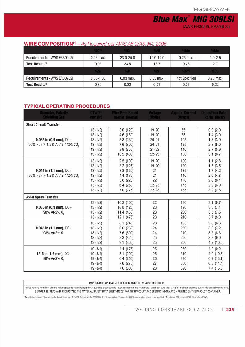
7/18/2019 c110 - Lincoln Electric Consumables 2014
http://slidepdf.com/reader/full/c110-lincoln-electric-consumables-2014 235/511W E L D I N G C O N S U M A B L E S C A TA L O G ı 235
Blue Max ®
MIG 309LSi
MIG (GMAW) WIRE
(AWS ER309Si, ER309LSi)
(1)Typical all weld metal. (2)See test results disclaimer on pg. 18. (3) AWS Requirement for ER309Si is 0.12% max. carbon. (4)Included in 0.50% max. for other elements not specified. (5)To estimate ESO, subtract 1/8 in (3 mm) from CTWD.
TYPICAL OPERATING PROCEDURES
Diameter, Polarity
Shielding Gas
CTWD(5)
mm (in)
Wire Feed Speed Voltage
(Volts)
Approx. Current
(Amps)
Deposition Rate
m/min (in/min) kg/hr (lb/hr)Short Circuit Transfer
0.035 in (0.9 mm), DC+
90% He / 7-1/2% Ar / 2-1/2% CO2
13 (1/2)
13 (1/2)
13 (1/2)
13 (1/2)
13 (1/2)
13 (1/2)
3.0
4.6
5.8
7.6
8.9
10.2
(120)
(180)
(230)
(300)
(350)
(400)
19-20
19-20
20-21
20-21
21-22
22-23
55
85
105
125
140
160
0.9
1.4
1.8
2.3
2.7
3.1
(2.0)
(3.0)
(3.9)
(5.0)
(5.9)
(6.7)
0.045 in (1.1 mm), DC+
90% He / 7-1/2% Ar / 2-1/2% CO2
13 (1/2)
13 (1/2)
13 (1/2)
13 (1/2)
13 (1/2)
13 (1/2)
13 (1/2)
2.5
3.2
3.8
4.4
5.6
6.4
7.0
(100)
(125)
(150)
(175)
(220)
(250)
(275)
19-20
19-20
21
21
22
22-23
22-23
100
120
135
140
170
175
185
1.1
1.5
1.7
2.0
2.6
2.9
3.2
(2.8)
(3.5)
(4.2)
(4.8)
(6.1)
(6.9)
(7.6)
Axial Spray Transfer
0.035 in (0.9 mm), DC+
98% Ar/2% O2
13 (1/2)
13 (1/2)
13 (1/2)
13 (1/2)
10.2
10.8
11.4
12.1
(400)
(425)
(450)
(475)
22
23
23
23
180
190
200
210
3.1
3.3
3.5
3.7
(6.7)
(7.1)
(7.5)
(8.0)
0.045 in (1.1 mm), DC+
98% Ar/2% O2
13 (1/2)
13 (1/2)
13 (1/2)
13 (1/2)13 (1/2)
6.1
6.6
7.6
8.39.1
(240)
(260)
(300)
(325)(360)
23
24
24
2525
195
230
240
250260
2.8
3.0
3.5
3.84.2
(6.6)
(7.2)
(8.3)
(9.0)(10.0)
1/16 in (1.6 mm), DC+
98% Ar/2% O2
19 (3/4)
19 (3/4)
19 (3/4)
19 (3/4)
19 (3/4)
4.4
5.1
6.4
7.0
7.6
(175)
(200)
(250)
(275)
(300)
25
26
26
27
28
260
310
330
360
390
4.3
4.9
6.2
6.8
7.4
(9.2)
(10.5)
(13.1)
(14.4)
(15.8)
WIRE COMPOSITION(1) – As Required per AWS A5.9/A5.9M: 2006
%C(3) %Cr %Ni %Mo %Mn
Requirements - AWS ER309LSi 0.03 max. 23.0-25.0 12.0-14.0 0.75 max. 1.0-2.5Test Results(3) 0.03 23.5 13.7 0.28 2.0
%Si %P %S %N(4) %Cu
Requirements - AWS ER309LSi 0.65-1.00 0.03 max. 0.03 max. Not Specified 0.75 max.
Test Results(3) 0.89 0.02 0.01 0.06 0.22
IMPORTANT: SPECIAL VENTILATION AND/OR EXHAUST REQUIRED
Fumes from the normal use of some welding products can contain significant quantities of components - such as chromium and manganese - which can lower the 5.0 mg/m3 maximum exposure guideline for general welding fume.
BEFORE USE, READ AND UNDERSTAND THE MATERIAL SAFETY DATA SHEET (MSDS) FOR THIS PRODUCT AND SPECIFIC INFORMATION PRINTED ON THE PRODUCT CONTAINER.

7/18/2019 c110 - Lincoln Electric Consumables 2014
http://slidepdf.com/reader/full/c110-lincoln-electric-consumables-2014 236/511236 ı T H E L I N C O L N E L E C T R I C C O M P A N Y
Blue Max ®
MIG 316LSi MIG (GMAW) WIRE
Welding Positions
Typical Applications
All
Molybdenum bearing austenitic stainless steels
Type 316 and 316L
High silicon level for increased puddle fluidityand toe wetting
Proprietary surface lubricant for steadyfeeding and arc stability
Molybdenum grade for increased corrosionresistance
Q2 Lot® - Certificate showing actual wirecomposition and calculated ferrite number(FN) available online
Controlled ferrite content for maximumcorrosion resistance
Conformances
Shielding Gas
Short Circuiting Transfer:90% Helium / 7-1/2% Argon / 2-1/2% CO
2
Axial Spray Transfer:98% Argon / Balance Oxygen
Stainless • AWS ER316Si, ER316LSi
Key Features
AWS A5.9/A5.9M: 2006:
ASME SFA-A5.9: ABS:
CWB/CSA W48-06:
EN ISO 14343-B:
ER316Si, ER316LSi
ER316Si, ER316LSiER316Si, ER316LSi
ER316LSi
SS316LSi
DIAMETERS / PACKAGING
Diameter 25 lb (11.3 kg)Plastic Spool
500 lb (227 kg)Accu-Trak® Drumin (mm)
0.030
0.0350.045
1/16
(0.8)
(0.9)(1.1)
(1.6)
ED023963
ED019298ED019299
ED019300
ED029772ED029773
MECHANICAL PROPERTIES(1) – As Required per AWS A5.9/A5.9M: 2006
Yield Strength(2)
MPa (ksi)Tensile Strength
MPa (ksi)Elongation
%Ferrite
Number
Requirements - AWS ER316Si, ER316LSi Not Specified
Test Results(3) - As-Welded 405 (59) 560 (81) 40 10

7/18/2019 c110 - Lincoln Electric Consumables 2014
http://slidepdf.com/reader/full/c110-lincoln-electric-consumables-2014 237/511W E L D I N G C O N S U M A B L E S C A TA L O G ı 237
Blue Max ®
MIG 316LSi
MIG (GMAW) WIRE
(AWS ER316Si, ER316LSi)
(1)Typical all weld metal. (2)See test results disclaimer on pg. 18. (3) AWS Requirement for ER309Si is 0.12% max. carbon. (4)Included in 0.50% max. for other elements not specified. (5)To estimate ESO, subtract 1/8 in (3 mm) from CTWD.
TYPICAL OPERATING PROCEDURES
Diameter, PolarityShielding Gas
CTWD(5) Wire Feed Speed Voltage(Volts)
Approx. Current(Amps)
Deposition Rate
mm (in) m/min (in/min) kg/hr (lb/hr)Short Circuit Transfer
0.035 in (0.9 mm), DC+
90% He / 7-1/2% Ar / 2-1/2% CO2
13 (1/2)
13 (1/2)
13 (1/2)
13 (1/2)
13 (1/2)
13 (1/2)
3.0
4.6
5.8
7.6
8.9
10.2
(120)
(180)
(230)
(300)
(350)
(400)
19-20
19-20
20-21
20-21
21-22
22-23
55
85
105
125
140
160
0.9
1.4
1.8
2.3
2.7
3.1
(2.0)
(3.0)
(3.9)
(5.0)
(5.9)
(6.7)
0.045 in (1.1 mm), DC+
90% He / 7-1/2% Ar / 2-1/2% CO2
13 (1/2)
13 (1/2)
13 (1/2)
13 (1/2)
13 (1/2)13 (1/2)
13 (1/2)
2.5
3.2
3.8
4.4
5.66.4
7.0
(100)
(125)
(150)
(175)
(220)(250)
(275)
19-20
19-20
21
21
2222-23
22-23
100
120
135
140
170175
185
1.1
1.5
1.7
2.0
2.62.9
3.2
(2.8)
(3.5)
(4.2)
(4.8)
(6.1)(6.9)
(7.6)
Axial Spray Transfer
0.035 in (0.9 mm), DC+
98% Ar/2% O2
13 (1/2)
13 (1/2)
13 (1/2)
13 (1/2)
10.2
10.8
11.4
12.1
(400)
(425)
(450)
(475)
22
23
23
23
180
190
200
210
3.1
3.3
3.5
3.7
(6.7)
(7.1)
(7.5)
(8.0)
0.045 in (1.1 mm), DC+
98% Ar/2% O2
13 (1/2)
13 (1/2)
13 (1/2)
13 (1/2)13 (1/2)
6.1
6.6
7.6
8.39.1
(240)
(260)
(300)
(325)(360)
23
24
24
2525
195
230
240
250260
2.8
3.0
3.5
3.84.2
(6.6)
(7.2)
(8.3)
(9.0)(10.0)
1/16 in (1.6 mm), DC+
98% Ar/2% O2
19 (3/4)
19 (3/4)
19 (3/4)
19 (3/4)
19 (3/4)
4.4
5.1
6.4
7.0
7.6
(175)
(200)
(250)
(275)
(300)
25
26
26
27
28
260
310
330
360
390
4.3
4.9
6.2
6.8
7.4
(9.2)
(10.5)
(13.1)
(14.4)
(15.8)
WIRE COMPOSITION(1) – As Required per AWS A5.9/A5.9M: 2006
%C(3) %Cr %Ni %Mo %Mn
Requirements - AWS ER316LSi 0.03 max. 18.0-20.0 11.0-14.0 2.0-3.0 1.0-2.5Test Results(3) 0.02 18.9 11.8 2.2 2.1
%Si %P %S %N(4) %Cu
Requirements - AWS ER316LSi 0.65-1.00 0.03 max. 0.03 max. Not Specified 0.75 max.
Test Results(3) 0.81 0.02 0.01 0.05 0.23
IMPORTANT: SPECIAL VENTILATION AND/OR EXHAUST REQUIRED
Fumes from the normal use of some welding products can contain significant quantities of components - such as chromium and manganese - which can lower the 5.0 mg/m3 maximum exposure guideline for general welding fume.
BEFORE USE, READ AND UNDERSTAND THE MATERIAL SAFETY DATA SHEET (MSDS) FOR THIS PRODUCT AND SPECIFIC INFORMATION PRINTED ON THE PRODUCT CONTAINER.

7/18/2019 c110 - Lincoln Electric Consumables 2014
http://slidepdf.com/reader/full/c110-lincoln-electric-consumables-2014 238/511238 ı T H E L I N C O L N E L E C T R I C C O M P A N Y
WIRE COMPOSITION(1) – As Required per AWS Similar to AWS A5.9/A5.9M: 2006
%C %Cr %Ni %Mo %Mn
Requirements - AWS ER307(4) 0.04-0.14 19.5-22.0 8.0-10.7 0.5-1.5 3.3-4.75
Test Results(3) 0.08 19.2 9.0 0.3 7.1
%Si %P %S %Cu
Requirements - AWS ER307(4) 0.30-0.65 0.03 0.03 0.75
Test Results(3) 0.80 0.03 0.03 0.30
(1)Typical all weld metal. (2)Measured with 0.2% offset. (3)See test results disclaimer on pg. 18. (4)Nearest classification.
Blue Max ®
LNM 307 MIG (GMAW) WIRE
Welding Positions
Typical Applications
All
Armor plate
Non-magneticaustenitic steel
Hardenable steel
Work hardeningmanganese steel
Designed for joining dissimilar steels
7% Mn increases resistance to hot cracking Q2 Lot® - Certificate showing actual wirecomposition and calculated ferrite number(FN) available online
Conformances
Shielding Gas
95% Argon / Balance CO2
Stainless • Similar to AWS ER307
Key Features
Similar to AWS A5.9/A5.9M: 2006:
EN ISO 14343-A:
ER307
G 18 8 Mn
DIAMETERS / PACKAGING
Diameter 33 lb (15 kg)Steel Spoolmm (in)
1.2 (0.045) ED031326
MECHANICAL PROPERTIES(1) – As Required per AWS Similar to AWS A5.9/A5.9M: 2006
Yield Strength(2)
MPa (ksi)Tensile Strength
MPa (ksi)Elongation
%
Charpy V-NotchJ (ft•lbf)
@ 20°C (68°F) @ -120°C (-184°F)
Requirements - AWS ER307(4) Not Specified
Test Results(3) - As-Welded 400 (58) 630 (91) 40 80 (59) 50 (37)
IMPORTANT: SPECIAL VENTILATION AND/OR EXHAUST REQUIRED
Fumes from the normal use of some welding products can contain significant quantities of components - such as chromium and manganese - which can lower the 5.0 mg/m3 maximum exposure guideline for general welding fume.
BEFORE USE, READ AND UNDERSTAND THE MATERIAL SAFETY DATA SHEET (MSDS) FOR THIS PRODUCT AND SPECIFIC INFORMATION PRINTED ON THE PRODUCT CONTAINER.

7/18/2019 c110 - Lincoln Electric Consumables 2014
http://slidepdf.com/reader/full/c110-lincoln-electric-consumables-2014 239/511W E L D I N G C O N S U M A B L E S C A TA L O G ı 239
IMPORTANT: SPECIAL VENTILATION AND/OR EXHAUST REQUIRED
Fumes from the normal use of some welding products can contain significant quantities of components - such as chromium and manganese - which can lower the 5.0 mg/m3 maximum exposure guideline for general welding fume.
BEFORE USE, READ AND UNDERSTAND THE MATERIAL SAFETY DATA SHEET (MSDS) FOR THIS PRODUCT AND SPECIFIC INFORMATION PRINTED ON THE PRODUCT CONTAINER.
WIRE COMPOSITION(1) – As Required per AWS A5.9/A5.9M: 2006
%C %Cr %Ni %Mo %Mn
Requirements - AWS ER347Si 0.08 max. 19.0-21.5 9.0-11.0 0.75 max. 1.0-2.5
Test Results(3) 0.04 19.2 9.9 0.3 1.3
%Si %P %S %Cu Nb(4)
Requirements - AWS ER347Si 0.65-1.00 0.03max. 0.03max. 0.75max. 10 X C min. / 1.0 max.
Test Results(3) 0.90 0.03 0.02 0.30 0.6
(1)Typical all weld metal. (2)Measured with 0.2% offset. (3)See test results disclaimer on pg. 18. (4)Included in 0.50% max. for other elements not specified.
Blue Max ®
LNM 347SiMIG (GMAW) WIRE
Welding Positions
Typical Applications
All
AISI 321, 321H, 347, 347H
CR-8C UNS S32100, S32109, S34700, S34709, J92710
Designed for joining Ti or Nb (Cb) stabilizedCrNi steels
Excellent resistance to intergranular corrosionand oxidizing environments
Q2 Lot® - Certificate showing actual wirecomposition and calculated ferrite number(FN) available onlineConformances
Shielding Gas
95% Argon / Balance CO2
97% Argon / Balance O2
AWS ER347Si • Stainless
Key Features
AWS A5.9/A5.9M:2006:
EN ISO 14343-A:
ER347Si
G 19 9 NbSi
DIAMETERS / PACKAGING
Diameter 33 lb (15 kg)Steel Spoolmm (in)
1.2 (0.045) ED031352
MECHANICAL PROPERTIES(1) – As Required per AWS A5.9/A5.9M: 2006
Yield Strength(2)
MPa (ksi)Tensile Strength
MPa (ksi)Elongation
%
Charpy V-NotchJ (ft•lbf)
@ 20°C (68°F)
Requirements - AWS ER347Si Not Specified
Test Results(3) - As-Welded 460 (68) 650 (94) 35 100 (74)
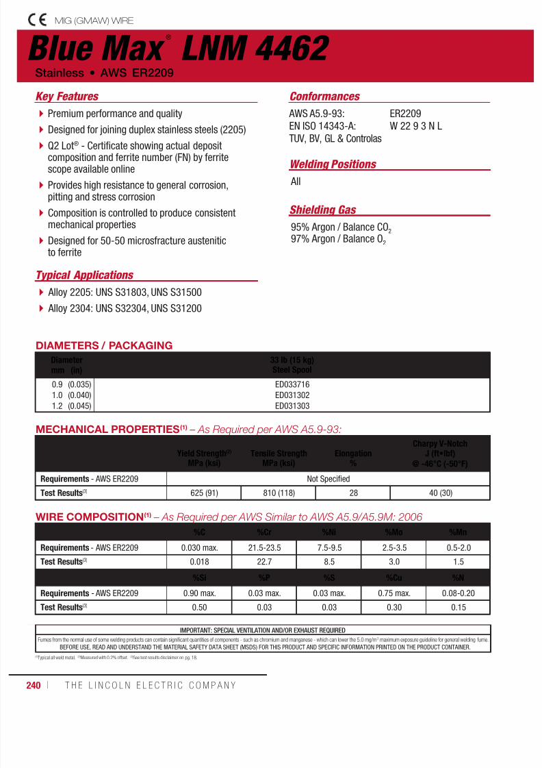
7/18/2019 c110 - Lincoln Electric Consumables 2014
http://slidepdf.com/reader/full/c110-lincoln-electric-consumables-2014 240/511240 ı T H E L I N C O L N E L E C T R I C C O M P A N Y
IMPORTANT: SPECIAL VENTILATION AND/OR EXHAUST REQUIRED
Fumes from the normal use of some welding products can contain significant quantities of components - such as chromium and manganese - which can lower the 5.0 mg/m3 maximum exposure guideline for general welding fume.
BEFORE USE, READ AND UNDERSTAND THE MATERIAL SAFETY DATA SHEET (MSDS) FOR THIS PRODUCT AND SPECIFIC INFORMATION PRINTED ON THE PRODUCT CONTAINER.
WIRE COMPOSITION(1) – As Required per AWS Similar to AWS A5.9/A5.9M: 2006
%C %Cr %Ni %Mo %Mn
Requirements - AWS ER2209 0.030 max. 21.5-23.5 7.5-9.5 2.5-3.5 0.5-2.0
Test Results(3) 0.018 22.7 8.5 3.0 1.5
%Si %P %S %Cu %N
Requirements - AWS ER2209 0.90 max. 0.03 max. 0.03 max. 0.75 max. 0.08-0.20
Test Results(3) 0.50 0.03 0.03 0.30 0.15
(1)Typical all weld metal. (2)Measured with 0.2% offset. (3)See test results disclaimer on pg. 18.
Blue Max ®
LNM 4462 MIG (GMAW) WIRE
Welding Positions
Typical Applications
All
Alloy 2205: UNS S31803, UNS S31500
Alloy 2304: UNS S32304, UNS S31200
Premium performance and quality
Designed for joining duplex stainless steels (2205) Q2 Lot® - Certificate showing actual depositcomposition and ferrite number (FN) by ferritescope available online
Provides high resistance to general corrosion,pitting and stress corrosion
Composition is controlled to produce consistentmechanical properties
Designed for 50-50 microsfracture austeniticto ferrite
Conformances
Shielding Gas
95% Argon / Balance CO2
97% Argon / Balance O2
Stainless • AWS ER2209
Key Features
AWS A5.9-93:
EN ISO 14343-A:TUV, BV, GL & Controlas
ER2209
W 22 9 3 N L
DIAMETERS / PACKAGING
Diameter 33 lb (15 kg)Steel Spoolmm (in)
0.9
1.01.2
(0.035)
(0.040)(0.045)
ED033716
ED031302ED031303
MECHANICAL PROPERTIES(1) – As Required per AWS A5.9-93:
Yield Strength(2)
MPa (ksi)Tensile Strength
MPa (ksi)Elongation
%
Charpy V-NotchJ (ft•lbf)
@ -46°C (-50°F)
Requirements - AWS ER2209 Not Specified
Test Results(3) 625 (91) 810 (118) 28 40 (30)
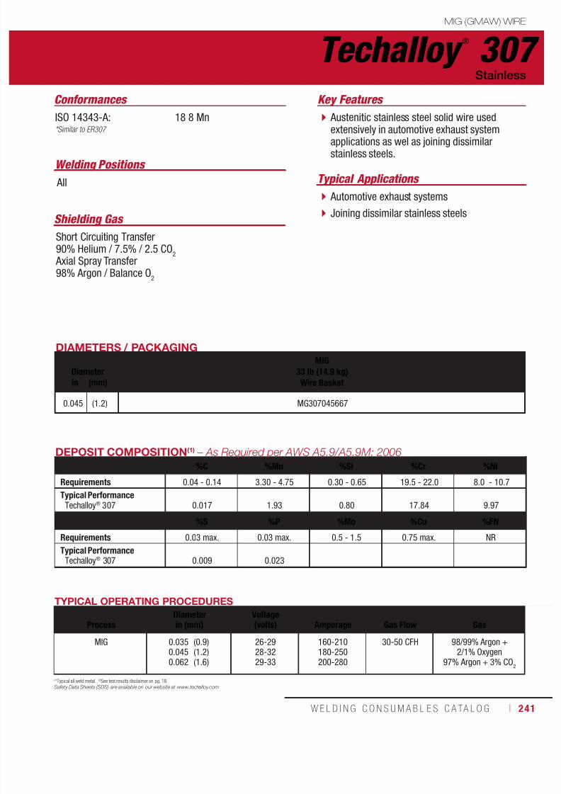
7/18/2019 c110 - Lincoln Electric Consumables 2014
http://slidepdf.com/reader/full/c110-lincoln-electric-consumables-2014 241/511W E L D I N G C O N S U M A B L E S C A TA L O G ı 241
Techalloy ®
307MIG (GMAW) WIRE
Stainless
ISO 14343-A: 18 8 Mn*Similar to ER307
DIAMETERS / PACKAGING
DiameterMIG
33 lb (14.9 kg)Wire Basketin (mm)
0.045 (1.2) MG307045667
TYPICAL OPERATING PROCEDURES
ProcessDiameterin (mm)
Voltage(volts)
Amperage
Gas Flow
Gas
MIG 0.0350.0450.062
(0.9)(1.2)(1.6)
26-2928-3229-33
160-210180-250200-280
30-50 CFH 98/99% Argon +2/1% Oxygen
97% Argon + 3% CO2
DEPOSIT COMPOSITION(1) – As Required per AWS A5.9/A5.9M: 2006
%C %Mn %Si %Cr %Ni
Requirements 0.04 - 0.14 3.30 - 4.75 0.30 - 0.65 19.5 - 22.0 8.0 - 10.7
Typical PerformanceTechalloy® 307 0.017 1.93 0.80 17.84 9.97
%S %P %Mo %Cu %FN
Requirements 0.03 max. 0.03 max. 0.5 - 1.5 0.75 max. NR
Typical PerformanceTechalloy® 307 0.009 0.023
Austenitic stainless steel solid wire usedextensively in automotive exhaust systemapplications as wel as joining dissimilarstainless steels.
Automotive exhaust systems
Joining dissimilar stainless steels
Conformances Key Features
Typical Applications
Shielding Gas
Short Circuiting Transfer90% Helium / 7.5% / 2.5 CO
2
Axial Spray Transfer
98% Argon / Balance O2
(1)Typical all weld metal. (2)See test results disclaimer on pg. 18.
Safety Data Sheets (SDS) are available on our website at www.techalloy.com
Welding Positions
All

7/18/2019 c110 - Lincoln Electric Consumables 2014
http://slidepdf.com/reader/full/c110-lincoln-electric-consumables-2014 242/511242 ı T H E L I N C O L N E L E C T R I C C O M P A N Y
Techalloy ®
308/308H MIG (GMAW) WIRE
Stainless • AWS ER308H
AWS: A5.9/A5.9M: 2006: ER308H
UNS: S30880
DIAMETERS / PACKAGING
DiameterMIG
33 lb (14.9 kg)Wire Basket
TIG10 lb (4.5 kg) Tube
30 lb (13.6 kg) Master Carton
SAW55 lb (25 kg)
Coilin (mm)
0.030
0.035
0.045
1/16
3/32
1/8
(0.8)
(0.9)
(1.1)
(1.6)
(2.4)
(3.2)
MG308H030667
MG308H035667
MG308H045667
MG308H062667 TG308H062638
TG308H093638
TG308H125638
SA308H093726
SA308H125726
TYPICAL OPERATING PROCEDURES
ProcessDiameterin (mm)
Voltage(volts)
Amperage
Gas Flow
Gas
MIG 0.0300.0350.0450.062
(0.8)(0.9)(1.1)(1.6)
26-2928-3229-33
160-210180-250200-280
30-50 CFH98/99% Argon +
2/1% Oxygen97% Argon + 3% CO
2
TIG 1/163/321/8
(1.6)(2.4)(3.2)
90-130120-175150-220
20-40 CFH 100% Argon
SAW 3/321/8
(2.4)(3.2)
28-3029-32
275-350350-450
Lincolnweld® P2007
DEPOSIT COMPOSITION(1) – As Required per AWS A5.9/A5.9M: 2006
%C %Cr %Ni %Mo %Mn
Requirements AWS ER308H 0.04 - 0.08 19.5 - 22.0 9.00 - 11.00 0.50 max. 1.0 - 2.5
Typical Performance(2)
Techalloy® 308/308H 0.06 19.9 9.7 0.07 1.8
%Si %P %S %Cu FN
Requirements AWS ER308H 0.30 - 0.65 0.04 max. 0.03 max 0.75 max. Not Required
Typical Performance(2)
Techalloy® 308/308H 0.44 0.02 0.006 0.10 5 - 12
Used to weld unstabilized austenitic stainlesssteels such as 302, 304H and 305.
Provide a high carbon deposit (minimumof .04% carbon) for high temperatureapplications.
Conformances Key Features
Chemical Petrochemicalindustries Distillery
Dairy Restaurant Equipment Catalytic Crackers Pulp and Paper
Typical Applications
(1)Typical all weld metal. (2)See test results disclaimer on pg. 18.
Safety Data Sheets (SDS) are available on our website at www.techalloy.com
Welding Positions
All
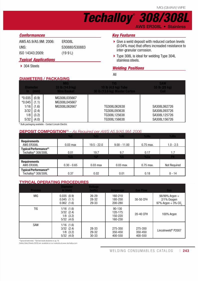
7/18/2019 c110 - Lincoln Electric Consumables 2014
http://slidepdf.com/reader/full/c110-lincoln-electric-consumables-2014 243/511W E L D I N G C O N S U M A B L E S C A TA L O G ı 243
Techalloy ®
308/308LMIG (GMAW) WIRE
AWS ER308L • Stainless
AWS A5.9/A5.9M: 2006: ER308L
UNS: S30880/S30883ISO 14343:2009: (19 9 L)
DIAMETERS / PACKAGING
DiameterMIG
33 lb (14.9 kg)Wire Basket
TIG10 lb (4.5 kg) Tube
30 lb (13.6 kg) Master Carton
SAW55 lb (25 kg)
Coilin (mm)
*0.035
*0.045
1/16
3/32
1/8
5/32
(0.9)
(1.1)
(1.6)
(2.4)
(3.2)
(4.0)
MG308L035667
MG308L045667
MG308L062667 TG308L062638
TG308L093638
TG308L125638
TG308L156638
SA308L062726
SA308L093726
SA308L125726
SA308L156726
* Bulk packaging available - Contact Lincoln Electric
TYPICAL OPERATING PROCEDURES
ProcessDiameterin (mm)
Voltage(volts)
Amperage
Gas Flow
Gas
MIG 0.0350.0450.062
(0.9)(1.1)(1.6)
26-2928-3229-33
160-210180-250200-280
30-50 CFH98/99% Argon +
2/1% Oxygen97% Argon + 3% CO
2
TIG 1/163/321/8
5/32
(1.6)(2.4)(3.2)(4.0)
90-130120-175150-220160-230
20-40 CFH 100% Argon
SAW 1/163/321/8
5/32
(1.6)(2.4)(3.2)(4.0)
28-3329-3230-33
275-350350-450400-550
275-350350-450400-550
Lincolnweld® P2007
DEPOSIT COMPOSITION(1) – As Required per AWS A5.9/A5.9M: 2006%C %Cr %Ni %Mo %Mn
Requirements AWS ER308L 0.03 max 19.5 - 22.0 9.00 - 11.00 0.75 max. 1.0 - 2.5
Typical Performance(2)
Techalloy® 308/308L 0.01 19.7 9.7 0.17 1.7
%Si %P %S %Cu FN
Requirements AWS ER308L 0.30 - 0.65 0.03 max 0.03 max. 0.75 max. Not Required
Typical Performance(2)
Techalloy® 308/308L 0.37 0.02 0.01 0.18 8 - 14
Give a weld deposit with reduced carbon levels(0.04% max) that offers increaded resistance tointer-granular corrosion.
Type 308L is ideal for welding Type 304Lstainless steels.
Conformances Key Features
304 Steels
Typical Applications
(1)Typical all weld metal. (2)See test results disclaimer on pg. 18.
Safety Data Sheets (SDS) are available on our website at www.techalloy.com
Welding Positions
All
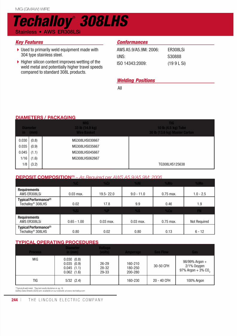
7/18/2019 c110 - Lincoln Electric Consumables 2014
http://slidepdf.com/reader/full/c110-lincoln-electric-consumables-2014 244/511

7/18/2019 c110 - Lincoln Electric Consumables 2014
http://slidepdf.com/reader/full/c110-lincoln-electric-consumables-2014 245/511W E L D I N G C O N S U M A B L E S C A TA L O G ı 245
Techalloy ®
309/309LMIG (GMAW) WIRE
AWS ER309L • Stainless
AWS A5.9/A5.9M: 2006: ER309L
UNS: 30983UNS: 30980ISO 14343:2009: (23 12 L)CWB
DIAMETERS / PACKAGING
Diameter
MIG
33 lb (14.9 kg)Wire Basket
TIG
10 lb (4.5 kg) Tube30 lb (13.6 kg) Master Carton
SAW
55 lb (25 kg)Coilin (mm)
0.035
0.045
1/16
3/32
1/8
5/32
(0.9)
(1.1)
(1.6)
(2.4)
(3.2)
(4.0)
MG309L035667
MG309L045667
MG309L062667 TG309L062638
TG309L093638
TG309L125638
TG309L156638
SA309L093726
SA309L125726
SA309L156726
TYPICAL OPERATING PROCEDURES
ProcessDiameterin (mm)
Voltage(volts)
Amperage
Gas Flow
Gas
MIG 0.0350.0451/16
(0.9)(1.1)(1.6)
26-2928-3229-33
160-210180-250200-280
30-50 CFH98/99% Argon +
2/1% Oxygen97% Argon + 3% CO
2
TIG 1/163/321/8
5/32
(1.6)(2.4)(3.2)(4.0)
90-130120-175150-220160-230
20 - 40 CFH 100% Argon
SAW 3/321/8
5/32
(2.4)(3.2)(4.0)
28-3329-3230-33
275-350350-450400-550
Lincolnweld® P2007
DEPOSIT COMPOSITION(1) – As Required per AWS A5.9/A5.9M: 2006%C %Cr %Ni %Mo %Mn
Requirements AWS ER309L 0.03 max. 23.0 - 25.0 12.0 - 14.0 0.75 max. 1.0 - 2.5
Typical Performance(2)
Techalloy® 309/309L 0.01 23.4 13.6 0.06 1.6
%Si %P %S %Cu FN
Requirements AWS ER309L 0.30 - 0.65 0.03 max. 0.03 max. 0.75 max. Not Required
Typical Performance(2)
Techalloy® 309/309L 0.38 0.02 0.007 0.07 9 - 14
(1)Typical all weld metal. (2)See test results disclaimer on pg. 18.
Safety Data Sheets (SDS) are available on our website at www.techalloy.com
Reduced carbon levels (0.04% max) that offersincreased resistance to inter-granular corrosion.
Ideal for joining stainless steels to themselves orto carbon or low alloy steels, and can be used attemperatures of up to 700°F (371°C).
Reduced carbon levels help prevent intergranularcorrosion.
Conformances Key Features
Do not exceed service temperatures of 700°F(371°C).
Typical Applications
Welding Positions
All

7/18/2019 c110 - Lincoln Electric Consumables 2014
http://slidepdf.com/reader/full/c110-lincoln-electric-consumables-2014 246/511246 ı T H E L I N C O L N E L E C T R I C C O M P A N Y
Techalloy ®
309LHS MIG (GMAW) WIRE
Stainless • AWS ER309LSi
AWS A5.9/A5.9M: 2006: ER309LSi
UNS: S30988ISO 14343:2009: (23 12 L Si)
DIAMETERS / PACKAGING
DiameterMIG
33 lb (14.9 kg)Wire Basketin (mm)
0.030
*0.035
*0.045
(0.8)
(0.9)
(1.1)
MG309LHS030667
MG309LHS035667
MG309LHS045667
* Bulk packaging available - Contact Lincoln Electric
TYPICAL OPERATING PROCEDURES
ProcessDiameterin (mm)
Voltage(volts)
Amperage
Gas Flow
Gas
MIG 0.0300.0350.0450.062
(0.8)(0.9)(1.1)(1.6)
26-2928-3229-33
160-210180-250200-280
30-50 CFH98/99% Argon +
2/1% Oxygen97% Argon + 3% CO
2
DEPOSIT COMPOSITION(1) – As Required per AWS A5.9/A5.9M: 2006
%C %Cr %Ni %Mo %Mn
Requirements AWS ER309LSi 0.03 max. 23.0 - 25.0 12.0 - 14.0 0.75 max. 1.0 - 2.5
Typical Performance(2)
Techalloy® 309LHS 0.01 23.2 13.8 0.04 1.8
%Si %P %S %Cu FN
Requirements AWS ER309LSi 0.65 - 1.00 0.03 max. 0.03 max. 0.75 max. Not Required
Typical Performance(2)
Techalloy® 309LHS 0.80 0.02 0.007 0.10 10 - 24
(1)Typical all weld metal. (2)See test results disclaimer on pg. 18.
Safety Data Sheets (SDS) are available on our website at www.techalloy.com
The same composition as Techalloy® 309Lwith higher silicon content to improve the beadappearance and increase welding ease.
Used for mild steel to stainless joiningapplications.
Excellent contour of the weld minimizes theneed for grinding.
Conformances Key Features
Welding Positions
All

7/18/2019 c110 - Lincoln Electric Consumables 2014
http://slidepdf.com/reader/full/c110-lincoln-electric-consumables-2014 247/511W E L D I N G C O N S U M A B L E S C A TA L O G ı 247
Techalloy ®
309LMoMIG (GMAW) WIRE
Similar to AWS ER309LMo • Stainless
Similar to AWS A5.9/A5.9M: 2006: ER309LMo
ISO 14343:2009: 23 12 2 L
DIAMETERS / PACKAGING
DiameterMIG
33 lb (14.9 kg)Wire Basket
TIG10 lb (4.5 kg) Tube
30 lb (13.6 kg) Master Carton
SAW55 lb (25 kg)
Coilin (mm)
0.035
0.045
1/16
3/32
1/8
5/32
(0.9)
(1.1)
(1.6)
(2.4)
(3.2)
(4.0)
MG309LMO035667
MG309LMO045667
MG309LMO062667
TG309LMO156638*
SA309LMO093726
*Made to Order (MTO)
TYPICAL OPERATING PROCEDURES
ProcessDiameterin (mm)
Voltage(volts)
Amperage
Gas Flow
Gas
MIG 0.035
0.045
0.062
(0.9)
(1.1)
(1.6)
26-29
28-32
29-33
160-210
180-250
200-280
30-50 CFH 98/99% Argon +
2/1% Oxygen
97% Argon + 3% CO2
TIG 5/32 (4.0) 160-230 20-40 CFH 100% Argon
SAW 3/32 (2.4) 28-33 275-350 Lincolnweld® P2007
DEPOSIT COMPOSITION(1) – As Required per AWS A5.9/A5.9M: 2006%C %Cr %Ni %Mo %Mn
Requirements(1)
AWS ER309LMo0.03 max. 23.0 - 25.0 12.0 - 14.0 2.0 - 3.0 1.0 - 2.5
Typical Performance(2)
Techalloy® 309LMo 0.01 22.3 15.0 2.6 1.40
%Si %P %S %Cu FN
Requirements(1)
AWS ER309LMo0.30 - 0.65 0.03 max. 0.03 max. 0.75 max. Not Required
Typical Performance(2)
Techalloy® 309LMo 0.40 0.02 0.01 0.10 6 - 12(1) Nearest classification
(1)Typical all weld metal. (2)See test results disclaimer on pg. 18.
Safety Data Sheets (SDS) are available on our website at www.techalloy.com
Similar to 309 with the exception for theaddition of 2.0 - 3.0% molybdenum toincrease its pitting corrosion resistance inhalide-containing environments.
Surfacing of base metals to improve theirresistance to corrosion.
Used to achieve a single-layer overlay witha chemical composition similar to that of a316L stainless steel.
Used for the first layer of multilayer overlayswith filler metals such as 316L or 317Lstainless steel.
Conformances Key Features
Welding Positions
All

7/18/2019 c110 - Lincoln Electric Consumables 2014
http://slidepdf.com/reader/full/c110-lincoln-electric-consumables-2014 248/511248 ı T H E L I N C O L N E L E C T R I C C O M P A N Y
Techalloy ®
310 MIG (GMAW) WIRE
Stainless • AWS ER310
AWS A5.9/A5.9M: 2006: ER310
UNS: S31080ISO 14343: 2009: (25 20)
DIAMETERS / PACKAGING
DiameterMIG
33 lb (14.9 kg)Wire Basket
TIG10 lb (4.5 kg) Tube
30 lb (13.6 kg) Master Carton
SAW55 lb (25 kg)
Coilin (mm)
0.035
0.045
1/16
3/32
1/8
(0.9)
(1.1)
(1.6)
(2.4)
(3.2)
MG310035667
MG310045667
MG310062667 TG310062638
TG310093638
TG310125638
SA310062726
SA310093726
TYPICAL OPERATING PROCEDURES
ProcessDiameterin (mm)
Voltage(volts)
Amperage
Gas Flow
Gas
MIG 0.0350.0451/16
(0.9)(1.1)(1.6)
26-2928-3229-33
160-210180-250200-280
30-50 CFH98/99% Argon +
2/1% Oxygen97% Argon + 3% CO
2
TIG 1/163/321/8
(1.6)(2.4)(3.2)
90-130120-175150-220
20-40 CFH 100% Argon
SAW 1/163/32
(1.6)(2.4) 28-33 275-350
Lincolnweld® P2007
DEPOSIT COMPOSITION(1) – As Required per AWS A5.9/A5.9M: 2006
%C %Cr %Ni %Mo %MnRequirements AWS ER310 0.08 - 0.15 25.0 - 28.0 20.0 - 22.5 0.75 max. 1.0 - 2.5
Typical Performance(2)
Techalloy® 310 0.11 27.1 21.0 1.90
%Si %P %S %Cu FN
Requirements AWS ER310 0.30 - 0.65 0.03 max. 0.03 max. 0.75 max. Not Required
Typical Performance(2)
Techalloy® 310 0.40 0.01 0.003 0.04
(1)Typical all weld metal. (2)See test results disclaimer on pg. 18.
Safety Data Sheets (SDS) are available on our website at www.techalloy.com
Used for welding stainless steels of similarcomposition in cast and wrought forms.
The weld deposit is fully austenitic, and assuch, calls for minimal heat input duringwelding.
Head shields
Furnace parts
Ducting
Conformances Key Features
Typical Applications
Welding Positions
All
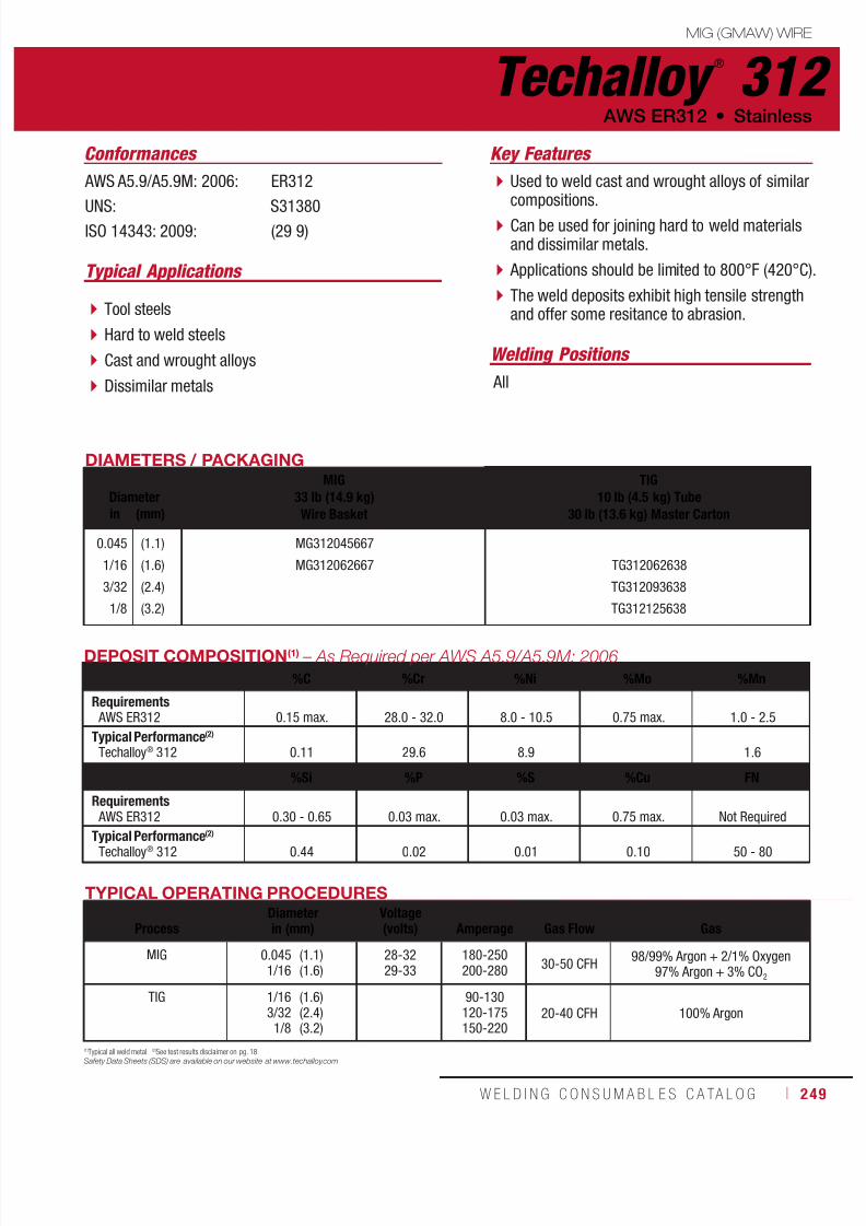
7/18/2019 c110 - Lincoln Electric Consumables 2014
http://slidepdf.com/reader/full/c110-lincoln-electric-consumables-2014 249/511W E L D I N G C O N S U M A B L E S C A TA L O G ı 249
Techalloy ®
312MIG (GMAW) WIRE
AWS ER312 • Stainless
AWS A5.9/A5.9M: 2006: ER312
UNS: S31380ISO 14343: 2009: (29 9)
DIAMETERS / PACKAGING
DiameterMIG
33 lb (14.9 kg)Wire Basket
TIG10 lb (4.5 kg) Tube
30 lb (13.6 kg) Master Cartonin (mm)
0.045
1/16
3/32
1/8
(1.1)
(1.6)
(2.4)
(3.2)
MG312045667
MG312062667 TG312062638
TG312093638
TG312125638
TYPICAL OPERATING PROCEDURES
ProcessDiameterin (mm)
Voltage(volts)
Amperage
Gas Flow
Gas
MIG 0.0451/16
(1.1)(1.6)
28-3229-33
180-250200-280
30-50 CFH98/99% Argon + 2/1% Oxygen
97% Argon + 3% CO2
TIG 1/163/321/8
(1.6)(2.4)(3.2)
90-130120-175150-220
20-40 CFH 100% Argon
DEPOSIT COMPOSITION(1) – As Required per AWS A5.9/A5.9M: 2006
%C %Cr %Ni %Mo %Mn
Requirements AWS ER312 0.15 max. 28.0 - 32.0 8.0 - 10.5 0.75 max. 1.0 - 2.5
Typical Performance(2)
Techalloy® 312 0.11 29.6 8.9 1.6
%Si %P %S %Cu FN
Requirements AWS ER312 0.30 - 0.65 0.03 max. 0.03 max. 0.75 max. Not Required
Typical Performance(2)
Techalloy® 312 0.44 0.02 0.01 0.10 50 - 80
(1)Typical all weld metal. (2)See test results disclaimer on pg. 18.
Safety Data Sheets (SDS) are available on our website at www.techalloy.com
Tool steels
Hard to weld steels
Cast and wrought alloys
Dissimilar metals
Used to weld cast and wrought alloys of similarcompositions.
Can be used for joining hard to weld materialsand dissimilar metals.
Applications should be limited to 800°F (420°C).
The weld deposits exhibit high tensile strengthand offer some resitance to abrasion.
Conformances
Typical Applications
Key Features
Welding Positions
All

7/18/2019 c110 - Lincoln Electric Consumables 2014
http://slidepdf.com/reader/full/c110-lincoln-electric-consumables-2014 250/511250 ı T H E L I N C O L N E L E C T R I C C O M P A N Y
Techalloy ®
316/316L MIG (GMAW) WIRE
Stainless • AWS ER316L
AWS A5.9/A5.9M: 2006: ER316LUNS: S31683UNS: S31680ISO 14343:2009: (19 12 3 L)
DIAMETERS / PACKAGING
DiameterMIG
33 lb (14.9 kg)
Wire Basket
TIG10 lb (4.5 kg) Tube
30 lb (13.6 kg) Master Carton
SAW55 lb (25 kg)
Coilin (mm)
0.0300.035
*0.0451/163/321/8
5/32
(0.8)(0.9)(1.1)(1.6)(2.4)(3.2)(4.0)
MG316L030667MG316L035667MG316L045667MG316L062667 TG316L062638
TG316L093638TG316L125638TG316L156638
SA316L093726SA316L125726SA316L156726
*Bulk packages available - Contact Lincoln Electric
TYPICAL OPERATING PROCEDURES
ProcessDiameterin (mm)
Voltage(volts)
Amperage
Gas Flow
Gas
MIG 0.0300.0350.0451/16
(0.8)(0.9)(1.1)(1.6)
26-2928-3229-33
160-210180-250200-280
30-50 CFH98/99% Argon +
2/1% Oxygen97% Argon + 3% CO
2
TIG 1/163/32
1/85/32
(1.6)(2.4)(3.2)(4.0)
90-130120-175150-220160-230
20-40 CFH 100% Argon
SAW 3/321/8
5/32
(2.4)(3.2)(4.0)
28-3329-3230-33
275-350350-450400-550
Lincolnweld® P2007
DEPOSIT COMPOSITION(1) – As Required per AWS A5.9/A5.9M: 2006
%C %Cr %Ni %Mo %Mn
Requirements AWS ER316L 0.03 max. 18.0 - 20.0 11.0 - 14.0 2.0 - 3.0 1.0 - 2.5
Typical Performance(2)
Techalloy® 316/316L 0.01 18.5 12.1 2.4 1.6
%Si %P %S %Cu FN
Requirements AWS ER316L 0.30 - 0.65 0.03 max. 0.03 max. 0.75 max. Not Required
Typical Performance(2)
Techalloy® 316/316L 0.36 0.02 0.01 0.09 6 - 12
(1)Typical all weld metal. (2)See test results disclaimer on pg. 18.
Safety Data Sheets (SDS) are available on our website at www.techalloy.com
Used for welding 316L base metals
The 2-3% molybdenum improves pittingcorrosion resistance of the weld deposit.
Low carbon content reduces the possibility ofcarbide precipitation and intergranular corrosion.
Power Generation
Chemical and Petrochemical Processing
Conformances Key Features
Typical Applications
Welding Positions
All
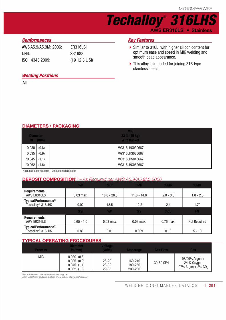
7/18/2019 c110 - Lincoln Electric Consumables 2014
http://slidepdf.com/reader/full/c110-lincoln-electric-consumables-2014 251/511W E L D I N G C O N S U M A B L E S C A TA L O G ı 251
Techalloy ®
316LHSMIG (GMAW) WIRE
AWS ER316LSi • Stainless
AWS A5.9/A5.9M: 2006: ER316LSi
UNS: S31688ISO 14343:2009: (19 12 3 L Si)
DIAMETERS / PACKAGING
DiameterMIG
33 lb (15 kg)Wire Basketin (mm)
0.030
0.035
*0.045
*0.062
(0.8)
(0.9)
(1.1)
(1.6)
MG316LHS030667
MG316LHS035667
MG316LHS045667
MG316LHS062667
*Bulk packages available - Contact Lincoln Electric
TYPICAL OPERATING PROCEDURES
ProcessDiameterin (mm)
Voltage(volts)
Amperage
Gas Flow
Gas
MIG 0.0300.0350.0450.062
(0.8)(0.9)(1.1)(1.6)
26-2928-3229-33
160-210180-250200-280
30-50 CFH98/99% Argon +
2/1% Oxygen97% Argon + 3% CO
2
DEPOSIT COMPOSITION(1) – As Required per AWS A5.9/A5.9M: 2006
%C %Cr %Ni %Mo %Mn
Requirements AWS ER316LSi 0.03 max. 18.0 - 20.0 11.0 - 14.0 2.0 - 3.0 1.0 - 2.5
Typical Performance(2)
Techalloy® 316LHS 0.02 18.5 12.2 2.4 1.70
%Si %P %S %Cu FN
Requirements AWS ER316LSi 0.65 - 1.0 0.03 max. 0.03 max. 0.75 max. Not Required
Typical Performance(2)
Techalloy® 316LHS 0.80 0.01 0.009 0.13 5 - 10
(1)Typical all weld metal. (2)See test results disclaimer on pg. 18.
Safety Data Sheets (SDS) are available on our website at www.techalloy.com
Similar to 316L, with higher silicon content foroptimum ease and speed in MIG welding andsmooth bead appearance.
This alloy is intended for joining 316 typestainless steels.
Conformances Key Features
Welding Positions
All
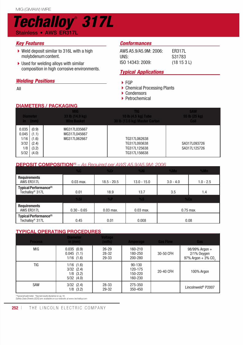
7/18/2019 c110 - Lincoln Electric Consumables 2014
http://slidepdf.com/reader/full/c110-lincoln-electric-consumables-2014 252/511252 ı T H E L I N C O L N E L E C T R I C C O M P A N Y
Techalloy ®
317L MIG (GMAW) WIRE
Stainless • AWS ER317L
AWS A5.9/A5.9M: 2006: ER317L
UNS: S31783ISO 14343: 2009: (18 15 3 L)
Conformances
DIAMETERS / PACKAGING
Diameter
MIG
33 lb (14.9 kg)Wire Basket
TIG
10 lb (4.5 kg) Tube30 lb (13.6 kg) Master Carton
SAW
55 lb (25 kg)Coilin (mm)
0.035
0.045
1/16
3/32
1/8
5/32
(0.9)
(1.1)
(1.6)
(2.4)
(3.2)
(4.0)
MG317L035667
MG317L045667
MG317L062667 TG317L062638
TG317L093638
TG317L125638
TG317L156638
SA317L093726
SA317L125726
TYPICAL OPERATING PROCEDURES
ProcessDiameterin (mm)
Voltage(volts)
Amperage
Gas Flow
Gas
MIG 0.0350.0451/16
(0.9)(1.1)(1.6)
26-2928-3229-33
160-210180-250200-280
30-50 CFH98/99% Argon +
2/1% Oxygen97% Argon + 3% CO
2
TIG 1/163/32
1/85/32
(1.6)(2.4)(3.2)(4.0)
90-130120-175150-220160-230
20-40 CFH 100% Argon
SAW 3/321/8
(2.4)(3.2)
28-3329-32
275-350350-450
Lincolnweld® P2007
DEPOSIT COMPOSITION(1) – As Required per AWS A5.9/A5.9M: 2006
%C %Cr %Ni %Mo %Mn
Requirements AWS ER317L 0.03 max. 18.5 - 20.5 13.0 - 15.0 3.0 - 4.0 1.0 - 2.5
Typical Performance(2)
Techalloy® 317L 0.01 18.9 13.7 3.5 1.4
%Si %P %S %Cu
Requirements AWS ER317L 0.30 - 0.65 0.03 max. 0.03 max. 0.75 max.
Typical Performance(2)
Techalloy® 317L 0.45 0.01 0.008 0.08
(1)Typical all weld metal. (2)See test results disclaimer on pg. 18.
Safety Data Sheets (SDS) are available on our website at www.techalloy.com
FGP Chemical Processing Plants Condensors Petrochemical
Typical Applications
Weld deposit similar to 316L with a highmolybdenum content.
Used for welding alloys with similarcomposition in high corrosive environments.
Key Features
Welding Positions
All
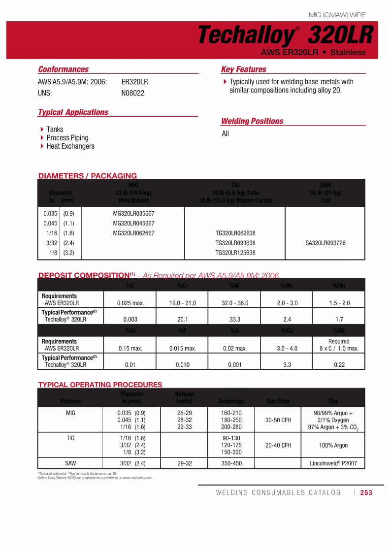
7/18/2019 c110 - Lincoln Electric Consumables 2014
http://slidepdf.com/reader/full/c110-lincoln-electric-consumables-2014 253/511W E L D I N G C O N S U M A B L E S C A TA L O G ı 253
Techalloy ®
320LRMIG (GMAW) WIRE
AWS ER320LR • Stainless
AWS A5.9/A5.9M: 2006: ER320LR
UNS: N08022
DIAMETERS / PACKAGING
DiameterMIG
33 lb (14.9 kg)Wire Basket
TIG10 lb (4.5 kg) Tube
30 lb (13.6 kg) Master Carton
SAW55 lb (25 kg)
Coilin (mm)
0.035
0.045
1/16
3/32
1/8
(0.9)
(1.1)
(1.6)
(2.4)
(3.2)
MG320LR035667
MG320LR045667
MG320LR062667 TG320LR062638
TG320LR093638
TG320LR125638
SA320LR093726
TYPICAL OPERATING PROCEDURES
ProcessDiameterin (mm)
Voltage(volts)
Amperage
Gas Flow
Gas
MIG 0.0350.0451/16
(0.9)(1.1)(1.6)
26-2928-3229-33
160-210180-250200-280
30-50 CFH98/99% Argon +
2/1% Oxygen97% Argon + 3% CO
2
TIG 1/163/321/8
(1.6)(2.4)(3.2)
90-130120-175150-220
20-40 CFH 100% Argon
SAW 3/32 (2.4) 29-32 350-450 Lincolnweld® P2007
DEPOSIT COMPOSITION(1) – As Required per AWS A5.9/A5.9M: 2006
%C %Cr %Ni %Mo %Mn
Requirements AWS ER320LR 0.025 max. 19.0 - 21.0 32.0 - 36.0 2.0 - 3.0 1.5 - 2.0
Typical Performance(2)
Techalloy® 320LR 0.003 20.1 33.3 2.4 1.7
%Si %P %S %Cu %Nb
Requirements AWS ER320LR 0.15 max. 0.015 max. 0.02 max. 3.0 - 4.0
Required8 x C / 1.0 max.
Typical Performance(2)
Techalloy® 320LR 0.01 0.010 0.001 3.3 0.22
(1)Typical all weld metal. (2)See test results disclaimer on pg. 18.
Safety Data Sheets (SDS) are available on our website at www.techalloy.com
Typically used for welding base metals withsimilar compositions including alloy 20.
Conformances Key Features
Tanks Process Piping Heat Exchangers
Typical Applications Welding Positions
All

7/18/2019 c110 - Lincoln Electric Consumables 2014
http://slidepdf.com/reader/full/c110-lincoln-electric-consumables-2014 254/511254 ı T H E L I N C O L N E L E C T R I C C O M P A N Y
Techalloy ®
330 MIG (GMAW) WIRE
Stainless • AWS ER330
AWS A5.9/A5.9M: 2006: ER330
UNS: N08331ISO 14343: 2009: (18 69 H)
DIAMETERS / PACKAGING
DiameterMIG
33 lb (14.9 kg)Wire Basket
TIG10 lb (4.5 kg) Tube
30 lb (13.6 kg) Master Cartonin (mm)
0.035
0.045
3/32
1/8
(0.9)
(1.1)
(2.4)
(3.2)
MG330035667
MG330045667
TG330093638
TG330125638
TYPICAL OPERATING PROCEDURES
ProcessDiameterin (mm)
Voltage(volts)
Amperage
Gas Flow
Gas
MIG 0.0350.045
(0.9)(1.1)
26-2928-32
160-210180-250 30-50 CFH
98/99% Argon + 2/1% Oxygen97% Argon + 3% CO
2
TIG 3/321/8
(2.4)(3.2)
120-175150-220
20-40 CFH 100% Argon
DEPOSIT COMPOSITION(1) – As Required per AWS A5.9/A5.9M: 2006
%C %Cr %Ni %Mo %Mn
Requirements AWS ER330 0.18 - 0.25 15.0 - 17.0 34.0 - 37.0 0.75 max. 1.0 - 2.5
Typical Performance(2)
Techalloy® 330 0.23 15.9 35.2 1.9
%Si %P %S %Cu
Requirements
AWS ER330 0.30 - 0.65 0.03 0.03 0.75 max.Typical Performance(2)
Techalloy® 330 0.42 0.01 0.005 0.10
(1)Typical all weld metal. (2)See test results disclaimer on pg. 18.
Safety Data Sheets (SDS) are available on our website at www.techalloy.com
Used to weld wrought and cast formsof stainless steels of similar chemicalcompositions, which offer good heat andscale resistance to 1800°F (980°C).
High sulfur environments adversely affectthe high temperature performance.
Heat input must be kept to a minimumduring welding to avoid ethe possibility ofmicro-fissuring.
Heat Treatment
Furnace Environments
Conformances Key Features
Typical Applications
Welding Positions
All
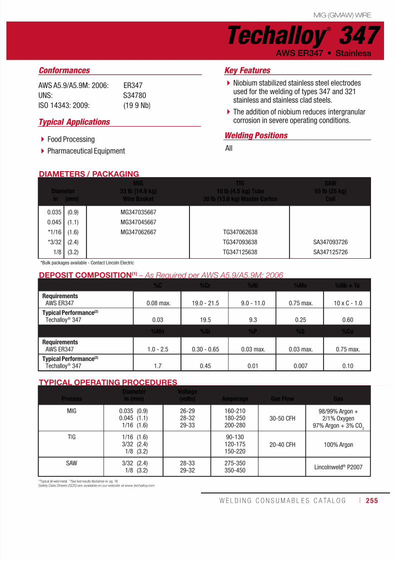
7/18/2019 c110 - Lincoln Electric Consumables 2014
http://slidepdf.com/reader/full/c110-lincoln-electric-consumables-2014 255/511W E L D I N G C O N S U M A B L E S C A TA L O G ı 255
Techalloy ®
347MIG (GMAW) WIRE
AWS ER347 • Stainless
AWS A5.9/A5.9M: 2006: ER347
UNS: S34780ISO 14343: 2009: (19 9 Nb)
DIAMETERS / PACKAGING
Diameter
MIG
33 lb (14.9 kg)Wire Basket
TIG
10 lb (4.5 kg) Tube30 lb (13.6 kg) Master Carton
SAW
55 lb (25 kg)Coilin (mm)
0.035
0.045
*1/16
*3/32
1/8
(0.9)
(1.1)
(1.6)
(2.4)
(3.2)
MG347035667
MG347045667
MG347062667 TG347062638
TG347093638
TG347125638
SA347093726
SA347125726
*Bulk packages available - Contact Lincoln Electric
TYPICAL OPERATING PROCEDURES
ProcessDiameterin (mm)
Voltage(volts)
Amperage
Gas Flow
Gas
MIG 0.0350.0451/16
(0.9)(1.1)(1.6)
26-2928-3229-33
160-210180-250200-280
30-50 CFH98/99% Argon +
2/1% Oxygen97% Argon + 3% CO
2
TIG 1/163/321/8
(1.6)(2.4)(3.2)
90-130120-175150-220
20-40 CFH 100% Argon
SAW 3/321/8
(2.4)(3.2)
28-3329-32
275-350350-450
Lincolnweld® P2007
DEPOSIT COMPOSITION(1) – As Required per AWS A5.9/A5.9M: 2006
%C %Cr %Ni %Mo %Nb + TaRequirements AWS ER347 0.08 max. 19.0 - 21.5 9.0 - 11.0 0.75 max. 10 x C - 1.0
Typical Performance(2)
Techalloy® 347 0.03 19.5 9.3 0.25 0.60
%Mn %Si %P %S %Cu
Requirements AWS ER347 1.0 - 2.5 0.30 - 0.65 0.03 max. 0.03 max. 0.75 max.
Typical Performance(2)
Techalloy® 347 1.7 0.45 0.01 0.007 0.10
(1)Typical all weld metal. (2)See test results disclaimer on pg. 18.
Safety Data Sheets (SDS) are available on our website at www.techalloy.com
Niobium stabilized stainless steel electrodesused for the welding of types 347 and 321stainless and stainless clad steels.
The addition of niobium reduces intergranularcorrosion in severe operating conditions.
Conformances Key Features
Food Processing
Pharmaceutical Equipment
Typical Applications
Welding Positions
All
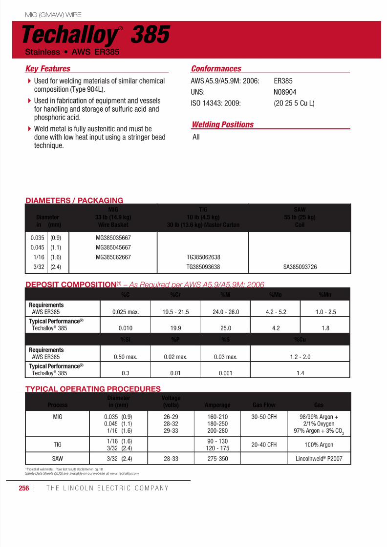
7/18/2019 c110 - Lincoln Electric Consumables 2014
http://slidepdf.com/reader/full/c110-lincoln-electric-consumables-2014 256/511256 ı T H E L I N C O L N E L E C T R I C C O M P A N Y
Techalloy ®
385 MIG (GMAW) WIRE
Stainless • AWS ER385
AWS A5.9/A5.9M: 2006: ER385
UNS: N08904ISO 14343: 2009: (20 25 5 Cu L)
DIAMETERS / PACKAGING
DiameterMIG
33 lb (14.9 kg)Wire Basket
TIG10 lb (4.5 kg)
30 lb (13.6 kg) Master Carton
SAW55 lb (25 kg)
Coilin (mm)
0.035
0.045
1/16
3/32
(0.9)
(1.1)
(1.6)
(2.4)
MG385035667
MG385045667
MG385062667 TG385062638
TG385093638 SA385093726
TYPICAL OPERATING PROCEDURES
ProcessDiameterin (mm)
Voltage(volts)
Amperage
Gas Flow
Gas
MIG 0.0350.0451/16
(0.9)(1.1)(1.6)
26-2928-3229-33
160-210180-250200-280
30-50 CFH 98/99% Argon +2/1% Oxygen
97% Argon + 3% CO2
TIG1/163/32
(1.6)(2.4)
90 - 130120 - 175
20-40 CFH 100% Argon
SAW 3/32 (2.4) 28-33 275-350 Lincolnweld® P2007
DEPOSIT COMPOSITION(1) – As Required per AWS A5.9/A5.9M: 2006
%C %Cr %Ni %Mo %Mn
Requirements AWS ER385 0.025 max. 19.5 - 21.5 24.0 - 26.0 4.2 - 5.2 1.0 - 2.5
Typical Performance(2)
Techalloy® 385 0.010 19.9 25.0 4.2 1.8
%Si %P %S %Cu
Requirements AWS ER385 0.50 max. 0.02 max. 0.03 max. 1.2 - 2.0
Typical Performance(2)
Techalloy®
385 0.3 0.01 0.001 1.4
(1)Typical all weld metal. (2)See test results disclaimer on pg. 18.
Safety Data Sheets (SDS) are available on our website at www.techalloy.com
Used for welding materials of similar chemicalcomposition (Type 904L).
Used in fabrication of equipment and vesselsfor handling and storage of sulfuric acid andphosphoric acid.
Weld metal is fully austenitic and must bedone with low heat input using a stringer beadtechnique.
Conformances Key Features
Welding Positions
All

7/18/2019 c110 - Lincoln Electric Consumables 2014
http://slidepdf.com/reader/full/c110-lincoln-electric-consumables-2014 257/511W E L D I N G C O N S U M A B L E S C A TA L O G ı 257
Techalloy ®
409NbMIG (GMAW) WIRE
AWS ER409Nb • Stainless
AWS A5.9/A5.9M: 2006: ER409Nb
UNS: S40940
DIAMETERS / PACKAGING
DiameterMIG
33 lb (14.9 kg)Wire Basket
TIG10 lb (4.5 kg)
30 lb (13.6 kg) Master Cartonin (mm)
0.035
0.045
1/16
3/32
(0.9)
(1.1)
(1.6)
(2.4)
MG409NB035667
MG409NB045667
TG409NB062638
TG409NB093638
TYPICAL OPERATING PROCEDURES
ProcessDiameterin (mm)
Voltage(volts)
Amperage
Gas Flow
Gas
MIG 0.035
0.045
(0.9)
(1.1)
26-29
28-32
160-210
180-25030-50 CFH
98/99% Argon + 2/1% Oxygen
97% Argon + 3% CO2
TIG 1/16
3/32
(1.6)
(2.4)
90-130
120-17520-40 CFH 100% Argon
DEPOSIT COMPOSITION(1) – As Required per AWS A5.9/A5.9M: 2006
%C %Cr %Ni %Mo %Nb
Requirements AWS ER409Nb 0.08 max 10.5 - 13.5 0.6 max. 0.50 max. 0.075 max.
Typical Performance(2)
Techalloy® 409Nb 0.04 11.5 0.4 0.03 0.50
%Mn %Si %P %S %Cu
Requirements
AWS ER409Nb 0.8 max. 1.0 max. 0.04 max. 0.03 max. 0.75 max.Typical Performance(2)
Techalloy® 409Nb 0.62 0.48 0.02 0.02 0.04
(1)Typical all weld metal. (2)See test results disclaimer on pg. 18.
Safety Data Sheets (SDS) are available on our website at www.techalloy.com
A ferritic stainless steel welding wire usedto weld Type 409 and 409Ti base materials.
The addition of niobium improves corrosionresistance and promotes a ferriticmicro-structure.
For the best results, welding must be donein a low heat input procedure and is notrecommended for multi-pass applications.
Conformances Key Features
Welding Positions
All

7/18/2019 c110 - Lincoln Electric Consumables 2014
http://slidepdf.com/reader/full/c110-lincoln-electric-consumables-2014 258/511258 ı T H E L I N C O L N E L E C T R I C C O M P A N Y
Techalloy ®
410 MIG (GMAW) WIRE
Stainless • AWS ER410
AWS A5.9/A5.9M: 2006: ER410
UNS: S41080ISO 14343: 2009: 13
DIAMETERS / PACKAGING
DiameterMIG
33 lb (14.9 kg)Wire Basket
TIG10 lb (4.5 kg)
30 lb (13.6 kg) Master Cartonin (mm)
0.035
*0.045
1/16
3/32
1/8
(0.9)
(1.1)
(1.6)
(2.4)
(3.2)
MG410035667
MG410045667
TG410062638
TG410093638
TG410125638
*Bulk packages available - Contact Lincoln Electric
DEPOSIT COMPOSITION(1) – As Required per AWS A5.9/A5.9M: 2006
%C %Cr %Ni %Mo %Mn
Requirements AWS ER410 0.12 max. 11.5 - 13.5 0.6 max. 0.75 max. 0.6 max.
Typical Performance(2)
Techalloy® 410 0.11 12.5 0.1 0.03 0.45
%Si %P %S %Cu
Requirements AWS ER410 0.5 max. 0.03 max. 0.03 max. 0.75 max.
Typical Performance(2)
Techalloy® 410 0.39 0.01 0.01 0.14
TYPICAL OPERATING PROCEDURES
ProcessDiameterin (mm)
Voltage(volts)
Amperage
Gas Flow
Gas
MIG 0.0350.045
(0.9)(1.1)
26-2928-32
160-210180-250
30-50 CFH98/99% Argon + 2/1% Oxygen
97% Argon + 3% CO2
TIG 1/163/32
1/8
(1.6)(2.4)(3.2)
90 - 130120 - 175150 - 220
20-40 CFH 100% Argon
(1)Typical all weld metal. (2)See test results disclaimer on pg. 18.
Safety Data Sheets (SDS) are available on our website at www.techalloy.com
Designed to weld stainless steels of similarchemical composition as well as to overlaycarbon steels to impart corrosion, erosion andabrasion resistance.
This material, being an air-hardening type, callsfor a pre-heat and inter-pass temperature ofnot less than 400°F (200° C) during welding. Surfacing Steel Mill Rolls
Furnace and Burner Parts
Turbine Parts
Conformances Key Features
Typical Applications
Welding Positions
All
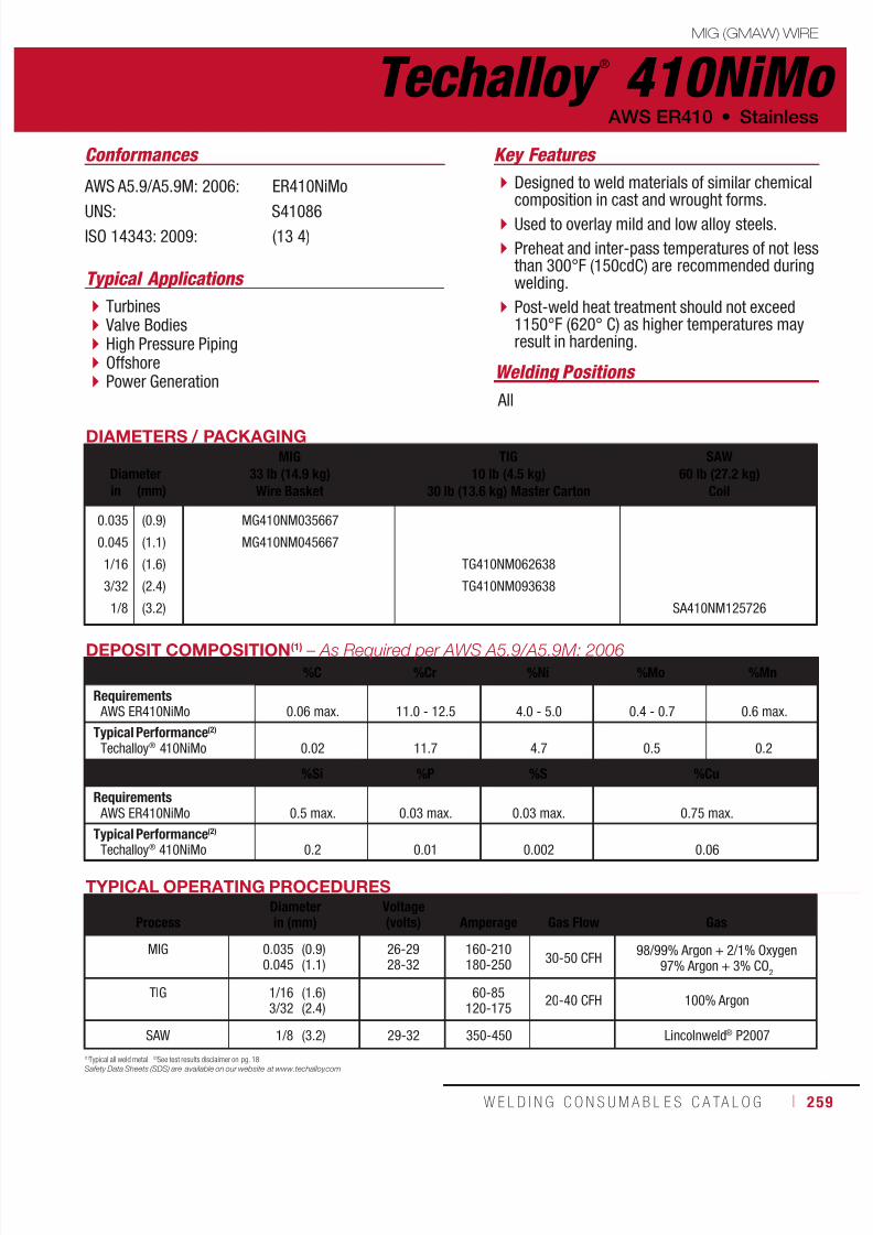
7/18/2019 c110 - Lincoln Electric Consumables 2014
http://slidepdf.com/reader/full/c110-lincoln-electric-consumables-2014 259/511W E L D I N G C O N S U M A B L E S C A TA L O G ı 259
Techalloy ®
410NiMoMIG (GMAW) WIRE
AWS ER410 • Stainless
AWS A5.9/A5.9M: 2006: ER410NiMo
UNS: S41086ISO 14343: 2009: (13 4)
DIAMETERS / PACKAGING
DiameterMIG
33 lb (14.9 kg)Wire Basket
TIG10 lb (4.5 kg)
30 lb (13.6 kg) Master Carton
SAW60 lb (27.2 kg)
Coilin (mm)
0.035
0.045
1/16
3/32
1/8
(0.9)
(1.1)
(1.6)
(2.4)
(3.2)
MG410NM035667
MG410NM045667
TG410NM062638
TG410NM093638
SA410NM125726
DEPOSIT COMPOSITION(1) – As Required per AWS A5.9/A5.9M: 2006
%C %Cr %Ni %Mo %Mn
Requirements AWS ER410NiMo 0.06 max. 11.0 - 12.5 4.0 - 5.0 0.4 - 0.7 0.6 max.
Typical Performance(2)
Techalloy® 410NiMo 0.02 11.7 4.7 0.5 0.2
%Si %P %S %Cu
Requirements AWS ER410NiMo 0.5 max. 0.03 max. 0.03 max. 0.75 max.
Typical Performance(2)
Techalloy® 410NiMo 0.2 0.01 0.002 0.06
TYPICAL OPERATING PROCEDURES
ProcessDiameterin (mm)
Voltage(volts)
Amperage
Gas Flow
Gas
MIG 0.0350.045
(0.9)(1.1)
26-2928-32
160-210180-250
30-50 CFH98/99% Argon + 2/1% Oxygen
97% Argon + 3% CO2
TIG 1/163/32
(1.6)(2.4)
60-85120-175
20-40 CFH 100% Argon
SAW 1/8 (3.2) 29-32 350-450 Lincolnweld® P2007
(1)Typical all weld metal. (2)See test results disclaimer on pg. 18.
Safety Data Sheets (SDS) are available on our website at www.techalloy.com
Turbines Valve Bodies High Pressure Piping Offshore Power Generation
Designed to weld materials of similar chemicalcomposition in cast and wrought forms.
Used to overlay mild and low alloy steels.
Preheat and inter-pass temperatures of not lessthan 300°F (150cdC) are recommended duringwelding.
Post-weld heat treatment should not exceed1150°F (620° C) as higher temperatures mayresult in hardening.
Conformances
Typical Applications
Key Features
Welding Positions
All

7/18/2019 c110 - Lincoln Electric Consumables 2014
http://slidepdf.com/reader/full/c110-lincoln-electric-consumables-2014 260/511260 ı T H E L I N C O L N E L E C T R I C C O M P A N Y
Techalloy ®
630 MIG (GMAW) WIRE
Stainless • AWS ER630
AWS A5.9/A5.9M: 2006: ER630
UNS: S17480
DIAMETERS / PACKAGING
DiameterMIG
33 lb (14.9 kg)Wire Basket
TIG10 lb (4.5 kg)
30 lb (13.6 kg) Master Carton
SAW60 lb (27.2 kg)
Coilin (mm)
0.035
0.045
1/16
3/32
(0.9)
(1.1)
(1.6)
(2.4)
MG630035667
MG630045667
TG630062638
TG630093638 SA630093692
DEPOSIT COMPOSITION(1) – As Required per AWS A5.9/A5.9M: 2006
%C %Cr %Ni %Mo %Nb
Requirements AWS ER630 0.05 max. 16.00 - 16.75 4.5 - 5.0 0.75 max. 0.15 - 0.30
Typical Performance(2)
Techalloy® 630 0.03 16.5 4.8 0.2 0.22
%Mn %Si %P %S %Cu
Requirements AWS ER630 0.25 - 0.75 0.75 max. 0.03 max. 0.03 max. 3.25 - 4.0
Typical Performance(2)
Techalloy®
630 0.54 0.43 0.02 0.02 3.6
TYPICAL OPERATING PROCEDURES
ProcessDiameterin (mm)
Voltage(volts)
Amperage
Gas Flow
Gas
MIG 0.0350.045
(0.9)(1.1)
26-2928-32
160-210180-250
30-50 CFH98/99% Argon + 2/1% Oxygen
97% Argon + 3% CO2
TIG 1/163/32
(1.6)(2.4)
90-130120-175
20-40 CFH 100% Argon
SAW 3/32 (2.4) Lincolnweld® P2007
(1)Typical all weld metal. (2)See test results disclaimer on pg. 18.
Safety Data Sheets (SDS) are available on our website at www.techalloy.com
Precipitation hardening stainless steel coveredelectrode used for welding materials of similarchemical composition such as 17-4 and 17-7.
Can be used in the as welded condition or maybe heat treated to obtain higher strength.
Mechanical properties of the alloy are greatlyinfluenced by the heat treatment.
Hydraulic Equipment Components
Impellers
Pump Shafts
Conformances Key Features
Typical Applications
Welding Positions
All
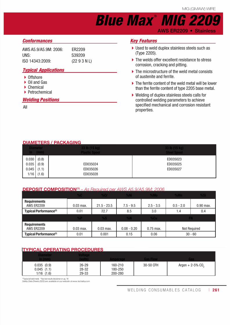
7/18/2019 c110 - Lincoln Electric Consumables 2014
http://slidepdf.com/reader/full/c110-lincoln-electric-consumables-2014 261/511W E L D I N G C O N S U M A B L E S C A TA L O G ı 261
Blue Max ®
MIG 2209MIG (GMAW) WIRE
AWS ER2209 • Stainless
AWS A5.9/A5.9M: 2006: ER2209
UNS: S39209ISO 14343:2009: (22 9 3 N L)
DIAMETERS / PACKAGINGDiameter 33 lb (15 kg)
Plastic Spool33 lb (15 kg)Steel Spoolin (mm)
0.030
0.035
0.045
1/16
(0.8)
(0.9)
(1.1)
(1.6)
ED035024
ED035026
ED035028
ED035023
ED035025
ED035027
TYPICAL OPERATING PROCEDURESDiameterin (mm)
Voltage(volts)
Amperage
Gas Flow
Gas
0.0350.0451/16
(0.9)(1.1)(1.6)
26-2928-3229-33
160-210180-250200-280
30-50 CFH Argon + 2-5% CO2
DEPOSIT COMPOSITION(1) – As Required per AWS A5.9/A5.9M: 2006
%C %Cr %Ni %Mo %Mn %Si
Requirements AWS ER2209 0.03 max. 21.5 - 23.5 7.5 - 9.5 2.5 - 3.5 0.5 - 2.0 0.90 max.
Typical Performance(2) 0.01 22.7 8.5 3.0 1.4 0.4
%P %S %N %Cu FN
Requirements AWS ER2209 0.03 max. 0.03 max. 0.08 - 0.20 0.75 max. Not Required
Typical Performance(2) 0.01 0.001 0.15 0.06 30 - 60
(1)Typical all weld metal. (2)See test results disclaimer on pg. 18.
Safety Data Sheets (SDS) are available on our website at www.techalloy.com
Offshore Oil and Gas Chemical Petrochemical
Used to weld duplex stainless steels such as(Type 2205).
The welds offer excellent resistance to stresscorrosion, cracking and pitting.
The microstructure of the weld metal consistsof austenite and ferrite.
The ferrite content of the weld metal will be lowerthan the ferrite content of type 2205 base metal.
Welding of duplex stainless steels calls forcontrolled welding parameters to achievespecified mechanical and corrosion resistant
properties.
Conformances
Typical Applications
Key Features
Welding Positions
All

7/18/2019 c110 - Lincoln Electric Consumables 2014
http://slidepdf.com/reader/full/c110-lincoln-electric-consumables-2014 262/511262 ı T H E L I N C O L N E L E C T R I C C O M P A N Y
Typical Applications
Process Pipework
Pumps and Valves
Pressure Vessels
A super-duplex grade electrode that providesmatching chemistry and mechanical propertycharacteristics to wrought super-duplex alloyssuch as 2507 and Zeron 100, as well as tosuper-duplex casting alloys (ATSM A890).
The electrode is over-alloyed 2-3% in nickel toprovide the optimum ferrite/austenite ratio inthe finished weld resulting iin high tensile andyield strength and superior resistance to stresscorrosion, cracking (SCC) and pitting corrosion.
Conformances Key Features
Blue Max ®
MIG 2594 MIG (GMAW) WIRE
Stainless • AWS ER2594
AWS A5.9/A5.9M: 2006: ER2594
UNS: S32750ISO 14343:2009: 25 9 4 N L
TYPICAL OPERATING PROCEDURES
ProcessDiameterin (mm)
Voltage(volts)
Amperage
Gas Flow
Gas
MIG 0.0350.045
(0.9)(1.1)
26-2928-32
160-210180-250
30-50 CFH Argon + 2-5% CO2
DEPOSIT COMPOSITION(1) – As Required per AWS A5.9/A5.9M: 2006
%C %Cr %Ni %Mo %Mn %Si
Requirements AWS ER2594 0.03 max. 24.0 - 27.0 8.0 - 10.5 2.5 - 4.5 2.5 max. 1.0 max.
Typical Performance(2) 0.02 24.6 8.6 3.8 0.8 0.3
%P %S %N %Cu %W FN
Requirements AWS ER2594 0.03 max. 0.02 max. 0.20 - 0.30 1.5 max. 1.00 max. Not Required
Typical Performance(2) 0.02 0.01 0.25 0.01 0.01 30 - 60
(1)Typical all weld metal. (2)See test results disclaimer on pg. 18.
Safety Data Sheets (SDS) are available on our website at www.techalloy.com
*This diameter is manufactured to mm.
Welding Positions
All
DIAMETERS / PACKAGINGDiameter 33 lb (15 kg)
Plastic Spool33 lb (15 kg)Steel Spoolin (mm)
0.0350.045
*0.045
1/16
(0.9)(1.1)
(1.2)
(1.6) ED035032
ED035029ED035030
ED035031
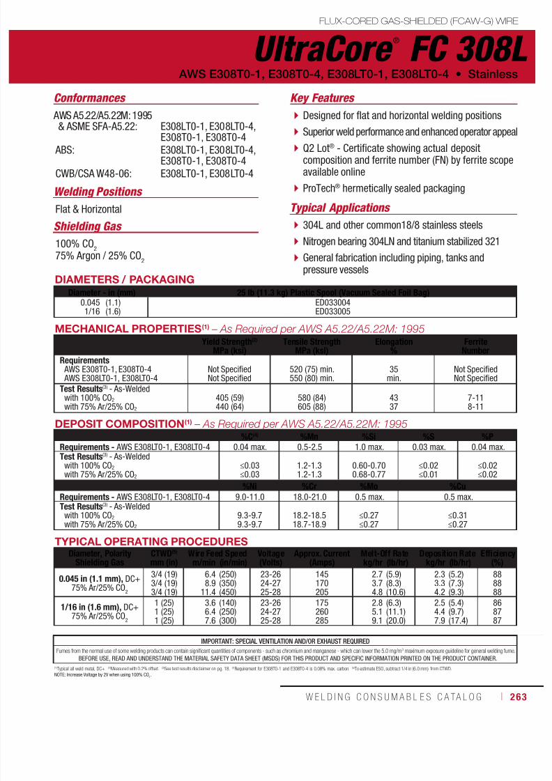
7/18/2019 c110 - Lincoln Electric Consumables 2014
http://slidepdf.com/reader/full/c110-lincoln-electric-consumables-2014 263/511W E L D I N G C O N S U M A B L E S C A TA L O G ı 263
DEPOSIT COMPOSITION(1) – As Required per AWS A5.22/A5.22M: 1995%C(4) %Mn %Si %S %P
Requirements - AWS E308LT0-1, E308LT0-4 0.04 max. 0.5-2.5 1.0 max. 0.03 max. 0.04 max.Test Results(3) - As-Welded
with 100% CO2
with 75% Ar/25% CO2
≤0.03≤0.03
1.2-1.31.2-1.3
0.60-0.700.68-0.77
≤0.02≤0.01
≤0.02≤0.02
%Ni %Cr %Mo %CuRequirements - AWS E308LT0-1, E308LT0-4 9.0-11.0 18.0-21.0 0.5 max. 0.5 max.Test Results(3) - As-Welded
with 100% CO2
with 75% Ar/25% CO2
9.3-9.79.3-9.7
18.2-18.518.7-18.9
≤0.27≤0.27
≤0.31≤0.27
(1)Typical all weld metal, DC+. (2)Measured with 0.2% offset. (3)See test results disclaimer on pg. 18. (4)Requirement for E308T0-1 and E308T0-4 is 0.08% max. carbon. (5)To estimate ESO, subtract 1/4 in (6.0 mm) from CTWD.NOTE: Increase Voltage by 2V when using 100% CO
2.
TYPICAL OPERATING PROCEDURESDiameter, Polarity
Shielding GasCTWD(5)
mm (in)Wire Feed Speed Voltage
(Volts)Approx. Current
(Amps)Melt-Off Rate Deposition Rate Efficiency
(%)m/min (in/min) kg/hr (lb/hr) kg/hr (lb/hr)
0.045 in (1.1 mm), DC+75% Ar/25% CO
2
3/4 (19)3/4 (19)3/4 (19)
6.48.9
11.4
(250)(350)(450)
23-2624-2725-28
145170205
2.73.74.8
(5.9)(8.3)(10.6)
2.33.34.2
(5.2)(7.3)(9.3)
888888
1/16 in (1.6 mm), DC+75% Ar/25% CO
2
1 (25)1 (25)1 (25)
3.66.47.6
(140)(250)(300)
23-2624-2725-28
175260285
2.85.19.1
(6.3)(11.1)(20.0)
2.54.47.9
(5.4)(9.7)(17.4)
868787
MECHANICAL PROPERTIES(1) – As Required per AWS A5.22/A5.22M: 1995Yield Strength(2)
MPa (ksi)Tensile Strength
MPa (ksi)Elongation
%Ferrite
NumberRequirements AWS E308T0-1, E308T0-4 AWS E308LT0-1, E308LT0-4
Not SpecifiedNot Specified
520 (75) min.550 (80) min.
35min.
Not SpecifiedNot Specified
Test Results(3) - As-Welded
with 100% CO2with 75% Ar/25% CO2
405 (59)440 (64) 580 (84)605 (88) 4337 7-118-11
IMPORTANT: SPECIAL VENTILATION AND/OR EXHAUST REQUIRED
Fumes from the normal use of some welding products can contain significant quantities of components - such as chromium and manganese - which can lower the 5.0 mg/m3 maximum exposure guideline for general welding fume.
BEFORE USE, READ AND UNDERSTAND THE MATERIAL SAFETY DATA SHEET (MSDS) FOR THIS PRODUCT AND SPECIFIC INFORMATION PRINTED ON THE PRODUCT CONTAINER.
UltraCore ®
FC 308LFLUX-CORED GAS-SHIELDED (FCAW-G) WIRE
Welding Positions
Typical Applications Flat & Horizontal
304L and other common18/8 stainless steels
Nitrogen bearing 304LN and titanium stabilized 321
General fabrication including piping, tanks and
pressure vessels
Designed for flat and horizontal welding positions
Superior weld performance and enhanced operator appeal Q2 Lot® - Certificate showing actual depositcomposition and ferrite number (FN) by ferrite scopeavailable online
ProTech® hermetically sealed packaging
Conformances
Shielding Gas
100% CO2
75% Argon / 25% CO2
AWS E308T0-1, E308T0-4, E308LT0-1, E308LT0-4 • Stainless
Key Features
AWS A5.22/A5.22M: 1995& ASME SFA-A5.22:
ABS:
CWB/CSA W48-06:
E308LT0-1, E308LT0-4,E308T0-1, E308T0-4E308LT0-1, E308LT0-4,E308T0-1, E308T0-4E308LT0-1, E308LT0-4
DIAMETERS / PACKAGINGDiameter - in (mm) 25 lb (11.3 kg) Plastic Spool (Vacuum Sealed Foil Bag)
0.0451/16
(1.1)(1.6)
ED033004ED033005

7/18/2019 c110 - Lincoln Electric Consumables 2014
http://slidepdf.com/reader/full/c110-lincoln-electric-consumables-2014 264/511264 ı T H E L I N C O L N E L E C T R I C C O M P A N Y
DIAMETERS / PACKAGING
Diameter 25 lb (11.3 kg) Plastic Spool(Vacuum Sealed Foil Bag)in (mm)
0.045
1/16
(1.1)
(1.6)
ED027949
ED027950
UltraCore ®
FCP 308L FLUX-CORED GAS-SHIELDED (FCAW-G) WIRE
Welding Positions
Typical Applications All
304L and other common 18/8 stainless steels
Nitrogen bearing 304LN and titaniumstabilized 321
General fabrication including piping, tanks,and pressure vessels
Designed for all-position welding
Superior weld performance and enhancedoperator appeal
Q2 Lot® - Certificate showing actual depositcomposition and ferrite number (FN) by ferritescope available online
ProTech® hermetically sealed packaging
Conformances
Shielding Gas
100% CO2
75% Argon / 25% CO2
Stainless • AWS E308LT1-1, E308LT1-4, E308T1-1, E308T1-4
Key Features
AWS A5.22/A5.22M: 1995& ASME SFA-A5.22:
ABS:
CWB/CSA W48-06:
E308LT1-1, E308LT1-4,E308T1-1, E308T1-4
E308LT1-1, E308LT1-4,E308T1-1, E308T1-4
E308LT1-1, E308LT1-4

7/18/2019 c110 - Lincoln Electric Consumables 2014
http://slidepdf.com/reader/full/c110-lincoln-electric-consumables-2014 265/511W E L D I N G C O N S U M A B L E S C A TA L O G ı 265
(1) Typical all weld metal, DC+. (2)Measured with 0.2% offset. (3)See test results disclaimer on pg. 18. (4)Requirement for E308T0-1 and E308T0-4 is 0.08% max. carbon. (5)To estimate ESO, subtract 1/4 in (6.0 mm) from CTWD.NOTE: Increase Voltage by 2V when using 100% CO
2
UltraCore ®
FCP 308L
FLUX-CORED GAS-SHIELDED (FCAW-G) WIRE
(AWS E308LT1-1, E308LT1-4, E308T1-1, E308T1-4)
DEPOSIT COMPOSITION(1)
%C(4) %Mn %Si %S %P
Requirements - AWS E308LT1-1 & E308LT1-4 0.04 max. 0.5 - 2.5 1.0 max. 0.03 max. 0.04 max.
Test Results(3)
As-Welded with 100% CO2
As-Welded with 75% Ar/25% CO2
0.03
0.03
1.4
1.5
0.6
0.7
0.02
0.02
0.03
0.03
%Ni %Cr %Mo %Cu
Requirements - AWS E308LT1-1 & E308LT1-4 9.0 - 11.0 18.0 - 21.0 0.5 max. 0.5 max.
Test Results(3)
As-Welded with 100% CO2
As-Welded with 75% Ar/25% CO2
9.8
9.7
18.6
18.9
0.3
0.3
0.3
0.3
TYPICAL OPERATING PROCEDURES
Diameter, Polarity
Shielding Gas
CTWD(5)
mm (in)
Wire Feed Speed Voltage
(Volts)
Approx. Current
(Amps)
Melt-Off Rate Deposition Rate Efficiency
(%)m/min (in/min) kg/hr (lb/hr) kg/hr (lb/hr)
0.045 in (1.1 mm), DC+
75% Ar/25% CO2
3/4 (19)
3/4 (19)
3/4 (19)
5.1
7.6
10.2
(200)
(300)
(400)
23-26
25-28
27-30
120
155
185
2.1
3.2
4.3
(4.7)
(7.0)
(9.4)
1.8
2.7
3.6
(4.0)
(6.0)
(7.9)
85
86
84
1/16 in (1.6 mm), DC+
75% Ar/25% CO2
1 (25)
1 (25)
1 (25)
3.6
5.1
8.9
(140)
(200)
(350)
23-26
24-27
26-29
175
210
290
2.8
4.0
7.0
(6.2)
(8.9)
(15.5)
2.4
3.4
5.9
(5.3)
(7.4)
(13.0)
85
83
84
MECHANICAL PROPERTIES(1) – As Required per AWS A5.22/A5.22M: 1995
Yield Strength(2)
MPa (ksi)Tensile Strength
MPa (ksi)Elongation
%Ferrite
Number
Requirements AWS E308LT1-1, E308LT1-4
AWS E308T1-1, E308T1-4
Not Specified
Not Specified
520 (75) min.
550 (80) min.
35
min.
Not Specified
Not Specified
Typical Performance(3)
As-Welded with 100% CO2
As-Welded with 75% Ar/25% CO2
407 (59)
421 (61)
566 (82)
587 (85)
42
39
6
7
IMPORTANT: SPECIAL VENTILATION AND/OR EXHAUST REQUIRED
Fumes from the normal use of some welding products can contain significant quantities of components - such as chromium and manganese - which can lower the 5.0 mg/m3 maximum exposure guideline for general welding fume.
BEFORE USE, READ AND UNDERSTAND THE MATERIAL SAFETY DATA SHEET (MSDS) FOR THIS PRODUCT AND SPECIFIC INFORMATION PRINTED ON THE PRODUCT CONTAINER.

7/18/2019 c110 - Lincoln Electric Consumables 2014
http://slidepdf.com/reader/full/c110-lincoln-electric-consumables-2014 266/511266 ı T H E L I N C O L N E L E C T R I C C O M P A N Y
DIAMETERS / PACKAGING
Diameter 25 lb (11.3 kg) Plastic Spool(Vacuum Sealed Foil Bag)in (mm)
0.045
1/16
(1.1)
(1.6)
ED033006
ED033007
Welding Positions
Typical Applications
Flat & Horizontal
Buffer layers and clad steels – overlays onCMn, mild steel or low alloy steels
Dissimilar joints – stainless types 410, 304L,321, and 316L to mild and low alloy steels
Designed for flat and horizontal weldingpositions
For welding dissimilar metals - stainless andmild or low alloy
Superior weld performance and enhancedoperator appeal
Q2 Lot® - Certificate showing actual depositcomposition and ferrite number (FN) by ferritescope available online
ProTech® hermetically sealed packaging
Conformances
Shielding Gas
100% CO2
75% Argon / 25% CO2
Key Features
AWS A5.22/A5.22M: 1995& ASME SFA-A5.22:
ABS:
CWB/CSA W48-06:
E309T0-1, E309T0-4,E309LT0-1, E309LT0-4
E309T0-1, E309T0-4,E309LT0-1, E309LT0-4
E309LT0-1, E309LT0-4
UltraCore ®
FC 309L FLUX-CORED GAS-SHIELDED (FCAW-G) WIRE
Stainless • AWS E309T0-1, E309T0-4, E309LT0-1, E309LT0-4

7/18/2019 c110 - Lincoln Electric Consumables 2014
http://slidepdf.com/reader/full/c110-lincoln-electric-consumables-2014 267/511W E L D I N G C O N S U M A B L E S C A TA L O G ı 267
UltraCore ®
FC 309L
FLUX-CORED GAS-SHIELDED (FCAW-G) WIRE
(AWS E309T0-1, E309T0-4, E309LT0-1, E309LT0-4)
DEPOSIT COMPOSITION(1) – As Required per AWS A5.22/A5.22M: 1995
%C(4) %Mn %Si %S %P
Requirements - AWS E309LTO-1 & E309LTO-4 0.04 max. 0.5 - 2.5 1.0 max. 0.03 max. 0.04 max.
Test Results(3)
As-Welded with 100% CO2
As-Welded with 75% Ar/25% CO2
≤0.03
≤0.03
1.3 - 1.5
1.2 - 1.5
0.65 - 0.75
0.72 - 0.78
≤0.01
≤0.01
≤0.02
≤0.02
%Ni %Cr %Mo %Cu
Requirements - AWS E309LTO-1 & E309LTO-4 12.0 - 14.0 22.0 - 25.0 0.5 max. 0.5 max.
Test Results(3)
As-Welded with 100% CO2
As-Welded with 75% Ar/25% CO2
12.2 - 12.8
12.2 - 12.8
22.6 - 23.9
23.0 - 24.0
≤0.27
≤0.23
≤0.31
≤0.27
TYPICAL OPERATING PROCEDURES
Diameter, Polarity
Shielding Gas
CTWD(5)
mm (in)
Wire Feed Speed Voltage
(Volts)
Approx. Current
(Amps)
Melt-Off Rate Deposition Rate Efficiency
(%)m/min (in/min) kg/hr (lb/hr) kg/hr (lb/hr)
0.045 in (1.1 mm), DC+
75% Ar/25% CO2
3/4 (19)
3/4 (19)
3/4 (19)
6.4
8.9
11.4
(250)
(350)
(450)
24-27
25-28
26-29
145
180
200
2.7
3.8
4.9
(5.9)
(8.3)
(10.7)
2.4
3.3
4.3
(5.2)
(7.3)
(9.4)
88
88
88
1/16 in (1.6 mm), DC+
75% Ar/25% CO2
1 (25)
1 (25)
1 (25)
3.6
6.4
7.6
(140)
(250)
(300)
22-25
24-27
26-29
170
245
270
2.8
5.1
6.1
(6.3)
(11.2)
(13.4)
2.5
4.4
5.3
(5.5)
(9.7)
(11.6)
87
87
87
MECHANICAL PROPERTIES(1) – As Required per AWS A5.22/A5.22M: 1995
Yield Strength(2)
MPa (ksi)Tensile Strength
MPa (ksi)Elongation
%Ferrite
Number
Requirements AWS E309LT0-1, E309LT0-4
AWS E309T0-1, E309T0-4
Not Specified
Not Specified
520 (75) min.
550 (80) min.
30
min.
Not Specified
Not Specified
Test Results(3)
As-Welded with 100% CO2
As-Welded with 75% Ar/25% CO2
440 (64)
435 (63)
570 (83)
580 (84)
36
37
15 - 21
15 - 21
IMPORTANT: SPECIAL VENTILATION AND/OR EXHAUST REQUIRED
Fumes from the normal use of some welding products can contain significant quantities of components - such as chromium and manganese - which can lower the 5.0 mg/m3 maximum exposure guideline for general welding fume.
BEFORE USE, READ AND UNDERSTAND THE MATERIAL SAFETY DATA SHEET (MSDS) FOR THIS PRODUCT AND SPECIFIC INFORMATION PRINTED ON THE PRODUCT CONTAINER.
(1)Typical all weld metal, DC+. (2)Measured with 0.2% offset. (3)See test results disclaimer on pg. 18. (4)Requirement for E309T1-1 and E309T1-4 is 0.10% max. carbon. (5)To estimate ESO, subtract 1/4 in (6.0 mm) from CTWD.NOTE: Increase Voltage by 2V when using 100% CO
2
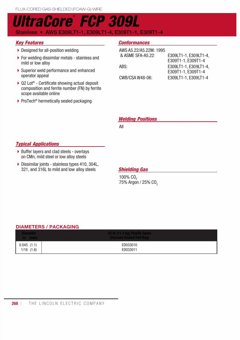
7/18/2019 c110 - Lincoln Electric Consumables 2014
http://slidepdf.com/reader/full/c110-lincoln-electric-consumables-2014 268/511268 ı T H E L I N C O L N E L E C T R I C C O M P A N Y
UltraCore ®
FCP 309L FLUX-CORED GAS-SHIELDED (FCAW-G) WIRE
Welding Positions
Typical Applications
All
Buffer layers and clad steels - overlayson CMn, mild steel or low alloy steels
Dissimilar joints - stainless types 410, 304L,321, and 316L to mild and low alloy steels
Designed for all-position welding
For welding dissimilar metals - stainless andmild or low alloy
Superior weld performance and enhancedoperator appeal
Q2 Lot® - Certificate showing actual depositcomposition and ferrite number (FN) by ferritescope available online
ProTech® hermetically sealed packaging
Conformances
Stainless • AWS E309LT1-1, E309LT1-4, E309T1-1, E309T1-4
Key Features
AWS A5.22/A5.22M: 1995& ASME SFA-A5.22:
ABS:
CWB/CSA W48-06:
E309LT1-1, E309LT1-4,E309T1-1, E309T1-4
E309LT1-1, E309LT1-4,E309T1-1, E309T1-4
E309LT1-1, E309LT1-4
DIAMETERS / PACKAGING
Diameter 25 lb (11.3 kg) Plastic Spool(Vacuum Sealed Foil Bag)in (mm)
0.045
1/16
(1.1)
(1.6)
ED033010
ED033011
Shielding Gas
100% CO2
75% Argon / 25% CO2
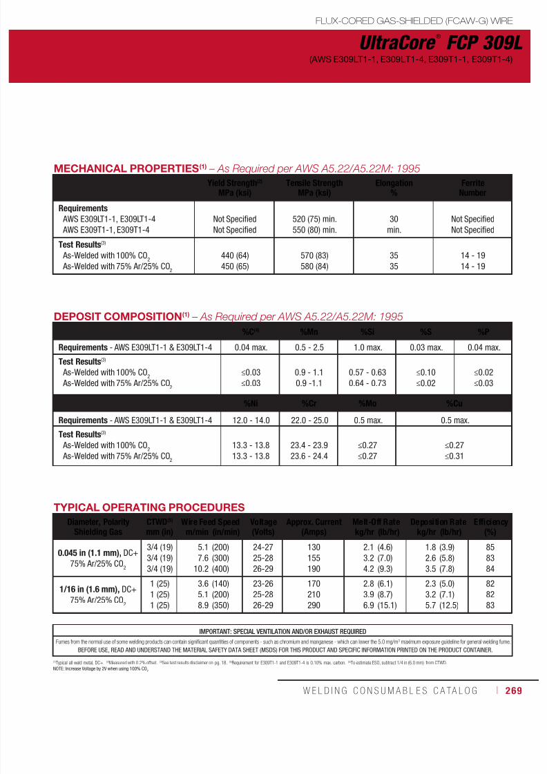
7/18/2019 c110 - Lincoln Electric Consumables 2014
http://slidepdf.com/reader/full/c110-lincoln-electric-consumables-2014 269/511W E L D I N G C O N S U M A B L E S C A TA L O G ı 269
UltraCore ®
FCP 309L
FLUX-CORED GAS-SHIELDED (FCAW-G) WIRE
(AWS E309LT1-1, E309LT1-4, E309T1-1, E309T1-4)
DEPOSIT COMPOSITION(1) – As Required per AWS A5.22/A5.22M: 1995
%C(4) %Mn %Si %S %P
Requirements - AWS E309LT1-1 & E309LT1-4 0.04 max. 0.5 - 2.5 1.0 max. 0.03 max. 0.04 max.
Test Results(3)
As-Welded with 100% CO2
As-Welded with 75% Ar/25% CO2
≤0.03
≤0.03
0.9 - 1.1
0.9 -1.1
0.57 - 0.63
0.64 - 0.73
≤0.10
≤0.02
≤0.02
≤0.03
%Ni %Cr %Mo %Cu
Requirements - AWS E309LT1-1 & E309LT1-4 12.0 - 14.0 22.0 - 25.0 0.5 max. 0.5 max.
Test Results(3)
As-Welded with 100% CO2
As-Welded with 75% Ar/25% CO2
13.3 - 13.8
13.3 - 13.8
23.4 - 23.9
23.6 - 24.4
≤0.27
≤0.27
≤0.27
≤0.31
(1)Typical all weld metal, DC+. (2)Measured with 0.2% offset. (3)See test results disclaimer on pg. 18. (4)Requirement for E309T1-1 and E309T1-4 is 0.10% max. carbon. (5)To estimate ESO, subtract 1/4 in (6.0 mm) from CTWD.NOTE: Increase Voltage by 2V when using 100% CO
2
TYPICAL OPERATING PROCEDURES
Diameter, Polarity
Shielding Gas
CTWD(5)
mm (in)
Wire Feed Speed Voltage
(Volts)
Approx. Current
(Amps)
Melt-Off Rate Deposition Rate Efficiency
(%)m/min (in/min) kg/hr (lb/hr) kg/hr (lb/hr)
0.045 in (1.1 mm), DC+
75% Ar/25% CO2
3/4 (19)
3/4 (19)
3/4 (19)
5.1
7.6
10.2
(200)
(300)
(400)
24-27
25-28
26-29
130
155
190
2.1
3.2
4.2
(4.6)
(7.0)
(9.3)
1.8
2.6
3.5
(3.9)
(5.8)
(7.8)
85
83
84
1/16 in (1.6 mm), DC+
75% Ar/25% CO2
1 (25)
1 (25)
1 (25)
3.6
5.1
8.9
(140)
(200)
(350)
23-26
25-28
26-29
170
210
290
2.8
3.9
6.9
(6.1)
(8.7)
(15.1)
2.3
3.2
5.7
(5.0)
(7.1)
(12.5)
82
82
83
MECHANICAL PROPERTIES(1) – As Required per AWS A5.22/A5.22M: 1995
Yield Strength(2)
MPa (ksi)Tensile Strength
MPa (ksi)Elongation
%Ferrite
Number
Requirements AWS E309LT1-1, E309LT1-4
AWS E309T1-1, E309T1-4
Not Specified
Not Specified
520 (75) min.
550 (80) min.
30
min.
Not Specified
Not Specified
Test Results(3)
As-Welded with 100% CO2
As-Welded with 75% Ar/25% CO2
440 (64)
450 (65)
570 (83)
580 (84)
35
35
14 - 19
14 - 19
IMPORTANT: SPECIAL VENTILATION AND/OR EXHAUST REQUIRED
Fumes from the normal use of some welding products can contain significant quantities of components - such as chromium and manganese - which can lower the 5.0 mg/m3 maximum exposure guideline for general welding fume.
BEFORE USE, READ AND UNDERSTAND THE MATERIAL SAFETY DATA SHEET (MSDS) FOR THIS PRODUCT AND SPECIFIC INFORMATION PRINTED ON THE PRODUCT CONTAINER.

7/18/2019 c110 - Lincoln Electric Consumables 2014
http://slidepdf.com/reader/full/c110-lincoln-electric-consumables-2014 270/511270 ı T H E L I N C O L N E L E C T R I C C O M P A N Y
UltraCore ®
FC 316L FLUX-CORED GAS-SHIELDED (FCAW-G) WIRE
Welding Positions
Typical Applications
Flat & Horizontal
1.5 – 3% Mo austenitic stainless steel
Suitable for Ti or Nb stabilized andnitrogen-bearing versions of the above alloys
Applications requiring good resistance topitting and general corrosion
Designed for flat and horizontal weldingpositions
Superior weld performance and enhancedoperator appeal
Q2 Lot® - Certificate showing actual depositcomposition and ferrite number (FN) by ferritescope available online
ProTech® hermetically sealed packaging
Conformances
Shielding Gas
100% CO2
75% Argon / 25% CO2
Stainless • AWS E316T0-1, E316T0-4, E316LT0-1, E316LT0-4
Key Features
AWS A5.22/A5.22M: 1995& ASME SFA-A5.22:
ABS:
CWB/CSA W48-06:
E316LT0-1, E316LT0-4,E316T0-1, E316T0-4
E316LT0-1, E316LT0-4,E316T0-1, E316T0-4
E316LT0-1, E316LT0-4
DIAMETERS / PACKAGING
Diameter 25 lb (11.3 kg) Plastic Spool(Vacuum Sealed Foil Bag)in (mm)
0.045
1/16
(1.1)
(1.6)
ED033008
ED033009

7/18/2019 c110 - Lincoln Electric Consumables 2014
http://slidepdf.com/reader/full/c110-lincoln-electric-consumables-2014 271/511W E L D I N G C O N S U M A B L E S C A TA L O G ı 271
UltraCore ®
FC 316L
FLUX-CORED GAS-SHIELDED (FCAW-G) WIRE
(AWS E316T0-1, E316T0-4, E316LT0-1, E316LT0-4)
DEPOSIT COMPOSITION(1) – As Required per AWS A5.22/A5.22M: 1995
%C(4) %Mn %Si %S %P
Requirements - AWS E316LT0-1 & E316LT0-4 0.04 max. 0.5 - 2.5 1.0 max. 0.03 max. 0.04 max.
Test Results(3)
As-Welded with 100% CO2
As-Welded with 75% Ar/25% CO2
≤0.03
≤0.03
1.2 - 1.3
1.1 - 1.4
0.60 - 0.70
0.70 - 0.73
≤0.01
≤0.01
≤0.02
≤0.02
%Ni %Cr %Mo %Cu
Requirements - AWS E316LT0-1 & E316LT0-4 11.0 - 14.0 17.0 - 20.0 2.0 - 3.0 0.5 max.
Test Results(3)
As-Welded with 100% CO2
As-Welded with 75% Ar/25% CO2
11.3 - 12.2
11.2 - 11.6
17.7 - 18.3
17.7 - 18.3
≤2.87
≤2.66
≤0.35
≤0.27
(1)Typical all weld metal, DC+. (2)Measured with 0.2% offset. (3)See test results disclaimer on pg. 18. (4)Requirement for E316T1-1 and E316T1-4 is 0.08% max. carbon. (5)To estimate ESO, subtract 1/4 in (6.0 mm) from CTWD.NOTE: Increase Voltage by 2V when using 100% CO
2
TYPICAL OPERATING PROCEDURES
Diameter, Polarity
Shielding Gas
CTWD(5)
mm (in)
Wire Feed Speed Voltage
(Volts)
Approx. Current
(Amps)
Melt-Off Rate Deposition Rate Efficiency
(%)m/min (in/min) kg/hr (lb/hr) kg/hr (lb/hr)
0.045 in (1.1 mm), DC+
75% Ar/25% CO2
3/4 (19)
3/4 (19)
3/4 (19)
6.4
8.9
11.4
(250)
(350)
(450)
23-26
24-27
25-28
140
170
200
2.7
3.8
4.8
(5.9)
(8.3)
(10.7)
2.3
3.2
4.2
(5.1)
(7.1)
(9.3)
86
86
87
1/16 in (1.6 mm), DC+
75% Ar/25% CO2
1 (25)
1 (25)
1 (25)
3.6
6.4
7.6
(140)
(250)
(300)
25-29
27-31
28-32
155
250
285
2.8
5.0
6.0
(6.2)
(11.0)
(13.2)
2.4
4.2
5.2
(5.3)
(9.3)
(11.4)
85
85
86
MECHANICAL PROPERTIES(1)
Yield Strength(2)
MPa (ksi)Tensile Strength
MPa (ksi)Elongation
%Ferrite
Number
Requirements AWS E316T0-1, E316T0-4
AWS E316LT0-1, E316LT0-4
Not Specified
Not Specified
520 (75) min.
550 (80) min.
30
min.
Not Specified
Not Specified
Test Results(3)
As-Welded with 100% CO2
As-Welded with 75% Ar/25% CO2
435 (63)
430 (62)
570 (83)
580 (84)
35
37
6 - 9
7 - 9
IMPORTANT: SPECIAL VENTILATION AND/OR EXHAUST REQUIRED
Fumes from the normal use of some welding products can contain significant quantities of components - such as chromium and manganese - which can lower the 5.0 mg/m3 maximum exposure guideline for general welding fume.
BEFORE USE, READ AND UNDERSTAND THE MATERIAL SAFETY DATA SHEET (MSDS) FOR THIS PRODUCT AND SPECIFIC INFORMATION PRINTED ON THE PRODUCT CONTAINER.
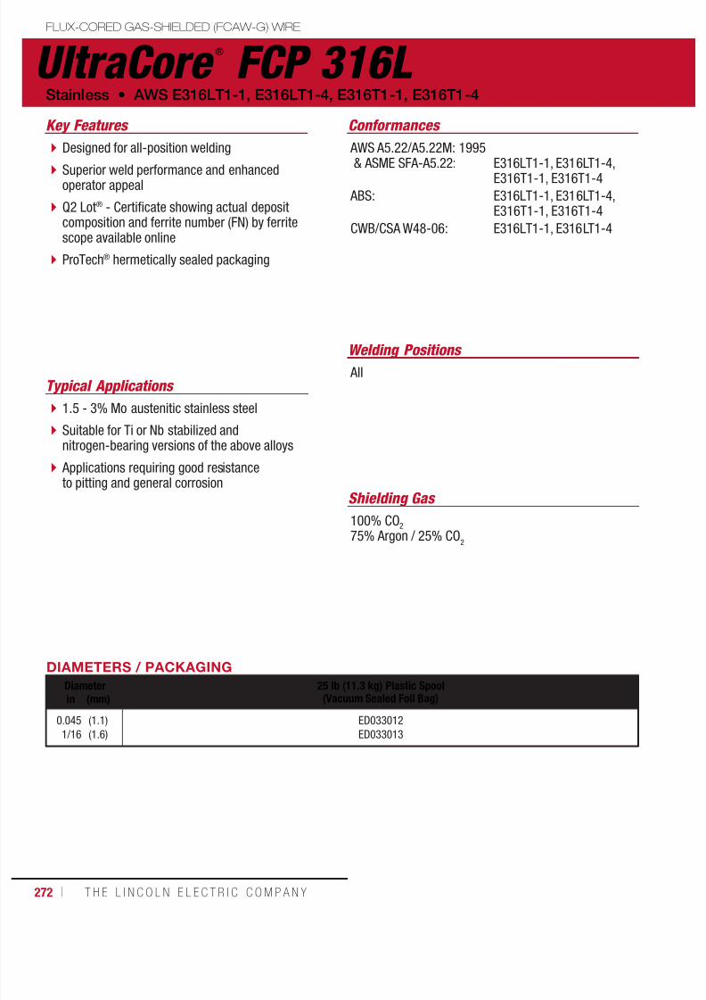
7/18/2019 c110 - Lincoln Electric Consumables 2014
http://slidepdf.com/reader/full/c110-lincoln-electric-consumables-2014 272/511272 ı T H E L I N C O L N E L E C T R I C C O M P A N Y
UltraCore ®
FCP 316L FLUX-CORED GAS-SHIELDED (FCAW-G) WIRE
Welding Positions
Typical Applications All
1.5 - 3% Mo austenitic stainless steel
Suitable for Ti or Nb stabilized andnitrogen-bearing versions of the above alloys
Applications requiring good resistanceto pitting and general corrosion
Designed for all-position welding
Superior weld performance and enhancedoperator appeal
Q2 Lot® - Certificate showing actual depositcomposition and ferrite number (FN) by ferritescope available online
ProTech® hermetically sealed packaging
Conformances
Shielding Gas
100% CO2
75% Argon / 25% CO2
Stainless • AWS E316LT1-1, E316LT1-4, E316T1-1, E316T1-4
Key Features
AWS A5.22/A5.22M: 1995& ASME SFA-A5.22:
ABS:
CWB/CSA W48-06:
E316LT1-1, E316LT1-4,E316T1-1, E316T1-4
E316LT1-1, E316LT1-4,E316T1-1, E316T1-4
E316LT1-1, E316LT1-4
DIAMETERS / PACKAGING
Diameter 25 lb (11.3 kg) Plastic Spool(Vacuum Sealed Foil Bag)in (mm)
0.045
1/16
(1.1)
(1.6)
ED033012
ED033013
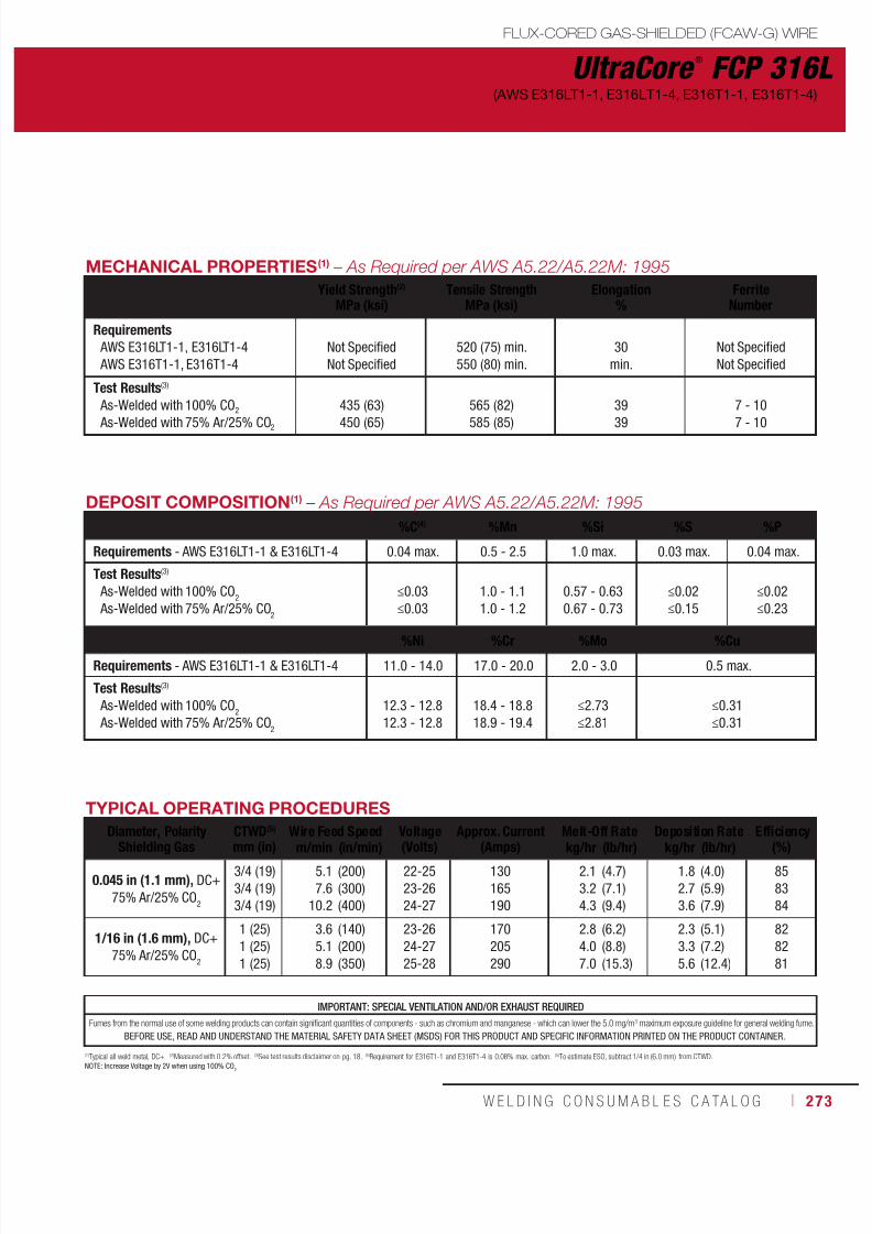
7/18/2019 c110 - Lincoln Electric Consumables 2014
http://slidepdf.com/reader/full/c110-lincoln-electric-consumables-2014 273/511W E L D I N G C O N S U M A B L E S C A TA L O G ı 273
UltraCore ®
FCP 316L
FLUX-CORED GAS-SHIELDED (FCAW-G) WIRE
(AWS E316LT1-1, E316LT1-4, E316T1-1, E316T1-4)
DEPOSIT COMPOSITION(1) – As Required per AWS A5.22/A5.22M: 1995
%C(4) %Mn %Si %S %P
Requirements - AWS E316LT1-1 & E316LT1-4 0.04 max. 0.5 - 2.5 1.0 max. 0.03 max. 0.04 max.
Test Results(3)
As-Welded with 100% CO2
As-Welded with 75% Ar/25% CO2
≤0.03
≤0.03
1.0 - 1.1
1.0 - 1.2
0.57 - 0.63
0.67 - 0.73
≤0.02
≤0.15
≤0.02
≤0.23
%Ni %Cr %Mo %Cu
Requirements - AWS E316LT1-1 & E316LT1-4 11.0 - 14.0 17.0 - 20.0 2.0 - 3.0 0.5 max.
Test Results(3)
As-Welded with 100% CO2
As-Welded with 75% Ar/25% CO2
12.3 - 12.8
12.3 - 12.8
18.4 - 18.8
18.9 - 19.4
≤2.73
≤2.81
≤0.31
≤0.31
(1)Typical all weld metal, DC+. (2)Measured with 0.2% offset. (3)See test results disclaimer on pg. 18. (4)Requirement for E316T1-1 and E316T1-4 is 0.08% max. carbon. (5)To estimate ESO, subtract 1/4 in (6.0 mm) from CTWD.NOTE: Increase Voltage by 2V when using 100% CO
2
TYPICAL OPERATING PROCEDURES
Diameter, Polarity
Shielding Gas
CTWD(5)
mm (in)
Wire Feed Speed Voltage
(Volts)
Approx. Current
(Amps)
Melt-Off Rate Deposition Rate Efficiency
(%)m/min (in/min) kg/hr (lb/hr) kg/hr (lb/hr)
0.045 in (1.1 mm), DC+
75% Ar/25% CO2
3/4 (19)
3/4 (19)
3/4 (19)
5.1
7.6
10.2
(200)
(300)
(400)
22-25
23-26
24-27
130
165
190
2.1
3.2
4.3
(4.7)
(7.1)
(9.4)
1.8
2.7
3.6
(4.0)
(5.9)
(7.9)
85
83
84
1/16 in (1.6 mm), DC+
75% Ar/25% CO2
1 (25)
1 (25)
1 (25)
3.6
5.1
8.9
(140)
(200)
(350)
23-26
24-27
25-28
170
205
290
2.8
4.0
7.0
(6.2)
(8.8)
(15.3)
2.3
3.3
5.6
(5.1)
(7.2)
(12.4)
82
82
81
MECHANICAL PROPERTIES(1) – As Required per AWS A5.22/A5.22M: 1995
Yield Strength(2)
MPa (ksi)Tensile Strength
MPa (ksi)Elongation
%Ferrite
Number
Requirements AWS E316LT1-1, E316LT1-4
AWS E316T1-1, E316T1-4
Not Specified
Not Specified
520 (75) min.
550 (80) min.
30
min.
Not Specified
Not Specified
Test Results(3)
As-Welded with 100% CO2
As-Welded with 75% Ar/25% CO2
435 (63)
450 (65)
565 (82)
585 (85)
39
39
7 - 10
7 - 10
IMPORTANT: SPECIAL VENTILATION AND/OR EXHAUST REQUIRED
Fumes from the normal use of some welding products can contain significant quantities of components - such as chromium and manganese - which can lower the 5.0 mg/m3 maximum exposure guideline for general welding fume.
BEFORE USE, READ AND UNDERSTAND THE MATERIAL SAFETY DATA SHEET (MSDS) FOR THIS PRODUCT AND SPECIFIC INFORMATION PRINTED ON THE PRODUCT CONTAINER.

7/18/2019 c110 - Lincoln Electric Consumables 2014
http://slidepdf.com/reader/full/c110-lincoln-electric-consumables-2014 274/511274 ı T H E L I N C O L N E L E C T R I C C O M P A N Y
SuperCore ®
347 FLUX-CORED GAS-SHIELDED (FCAW-G) WIRE
DIAMETERS / PACKAGING
Diameter 15 kg (33 lb)Spoolmm (in)
1.2 (0.045) ED034129
ApplicationsKey Features
Shielding Gas
Welding Positions
Conformances
High deposition flat / horizontal wire
Improved bead appearance
Food
Brewery Pharmaceutical Equipment
Architectural
General Fabrication
75-80% Argon / Balance CO2
100% CO2
Flat and horizontal
AWS A5.28
BS EN ISO 17633-A
BS EN ISO 17633-B
E347T0-1/4
T19 9 Nb R C/M 3
TS347-FB0
TYPICAL OPERATING PROCEDURESDiameterin (mm)
Amp-Volt Range
Typical
Stickoutin (mm)
1.2 (0.045) DC+120 - 280A
22 - 34V180A, 29V
15 - 25(5/8 - 1)
DEPOSIT COMPOSITION(1) - As Required per AWS A5.28%C %Mn %Si %S %P %Cr
Requirements AWS E347T0-1/4 0.08 max. 0.5 - 2.0 1.0 max. 0.025 max. 0.030 max. 18.0 - 21.0
Typical Results(3) 0.03 1.20 0.40 0.01 0.02 19.0
%Ni %Mo %Nb %Cu FN
Requirements AWS E347T0-1/4 9.0 - 11.0 0.3 max. 8x - 1.0 0.3 max. 4 - 12
Typical Results(3) 10.5 0.10 0.50 -0.90 8.0
MECHANICAL PROPERTIES(1) - As Required per AWS A5.28
Yield Strength(2)
MPa (ksi)
Tensile Strength
MPa (ksi)
Elongation %
Charpy V-NotchJ (ft•lbf)
4.0 dia. 5.0 dia. @ 20°C (68°F)
Requirements AWS E347T0-1/4 350 min. 550 min. 30 min. 25 min. –
Typical Results As-Welded 435 600 47 42 90
(1)Typical all weld metal. (2)Measured with 0.2% offset. (3)See test results disclaimer below.
NOTE: Additional test data available upon request.
AWS E347T0-1/4
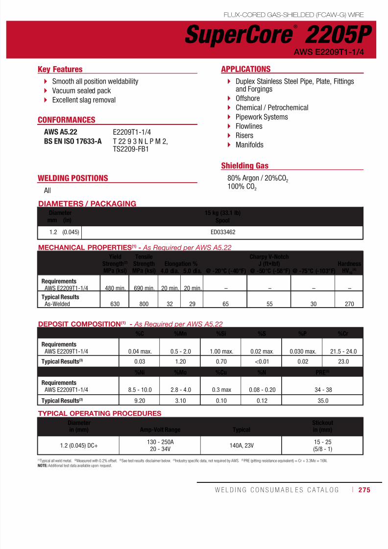
7/18/2019 c110 - Lincoln Electric Consumables 2014
http://slidepdf.com/reader/full/c110-lincoln-electric-consumables-2014 275/511W E L D I N G C O N S U M A B L E S C A TA L O G ı 275
SuperCore ®
2205PFLUX-CORED GAS-SHIELDED (FCAW-G) WIRE
AWS E2209T1-1/4
DIAMETERS / PACKAGINGDiameter 15 kg (33.1 lb)
Spoolmm (in)
1.2 (0.045) ED033462
APPLICATIONSKey Features
Shielding Gas
WELDING POSITIONS
CONFORMANCES
Smooth all position weldability
Vacuum sealed pack Excellent slag removal
Duplex Stainless Steel Pipe, Plate, Fittingsand Forgings
Offshore
Chemical / Petrochemical
Pipework Systems
Flowlines
Risers
Manifolds
80% Argon / 20%CO2
100% CO2 All
AWS A5.22BS EN ISO 17633-A
E2209T1-1/4
T 22 9 3 N L P M 2,TS2209-FB1
DEPOSIT COMPOSITION(1) - As Required per AWS A5.22
%C %Mn %Si %S %P %Cr
Requirements AWS E2209T1-1/4 0.04 max. 0.5 - 2.0 1.00 max. 0.02 max. 0.030 max. 21.5 - 24.0
Typical Results(3) 0.03 1.20 0.70 <0.01 0.02 23.0
%Ni %Mo %Cu %N PRE
(5)
Requirements AWS E2209T1-1/4 8.5 - 10.0 2.8 - 4.0 0.3 max 0.08 - 0.20 34 - 38
Typical Results(3) 9.20 3.10 0.10 0.12 35.0
MECHANICAL PROPERTIES(1) - As Required per AWS A5.22
YieldStrength(2)
MPa (ksi)
TensileStrengthMPa (ksi)
Elongation %
Charpy V-NotchJ (ft•lbf) Hardness
HV10(4)4.0 dia. 5.0 dia. @ -20°C (-40°F) @ -50°C (-58°F) @ -75°C (-103°F)
Requirements AWS E2209T1-1/4 480 min. 690 min. 20 min. 20 min. – – – –
Typical Results As-Welded 630 800 32 29 65 55 30 270
(1)Typical all weld metal. (2)Measured with 0.2% offset. (3)See test results disclaimer below. (4)Industry specific data, not required by AWS. (5)PRE (pitting resistance equivalent) = Cr + 3.3Mo = 16N.
NOTE: Additional test data available upon request.
TYPICAL OPERATING PROCEDURES
Diameterin (mm)
Amp-Volt Range
Typical
Stickoutin (mm)
1.2 (0.045) DC+130 - 250A
20 - 34V140A, 23V
15 - 25(5/8 - 1)

7/18/2019 c110 - Lincoln Electric Consumables 2014
http://slidepdf.com/reader/full/c110-lincoln-electric-consumables-2014 276/511276 ı T H E L I N C O L N E L E C T R I C C O M P A N Y
MECHANICAL PROPERTIES(1)
– As Required per AWS A5.9/A5.9M: 2006Yield Strength(2)
MPa (ksi)Tensile Strength
MPa (ksi)Elongation
%Ferrite
Number
Requirements - AWS ER308, ER308L Not Specified
Test Results(3, 5) - As-Welded 380 (55) 565 (82) 42 15
WIRE & DEPOSIT COMPOSITION(1)
%C(4) %Cr %Ni %Mo %Mn %Si
Requirements - AWS ER308L 0.03 max. 19.5 - 22.0 9.0 - 11.0 0.75 max. 1.0 - 2.5 0.30 - 0.65
Typical Performance(3)
Wire Composition
All Weld Metal Composition(5)
0.02
0.02
20.1
19.0 - 19.5
9.8
9.8
0.10
0.10
1.8
1.5 - 1.9
0.50
0.50 - 0.80
(1)Typical all weld metal. (2)Measured with 0.2% offset. (3)See test results disclaimer on pg. 18. (4) AWS Requirement for ER308 is 0.08% max. carbon.(5)Results shown correspond with the recommended Lincolnweld® and Blue Max® fluxes listed above, but not required per AWS A5.9-93.
TYPICAL OPERATING PROCEDURESDiameter Wire Feed Speed Voltage
(volts)Current(amps)in (mm) m/min (in/min)
5/64
3/32
1/8
5/32
(2.0)
(2.4)
(3.2)
(4.0)
2.0-6.1 (80-240)
1.5-5.3 (60-210)
0.9-2.8 (35-110)
0.8-1.9 (30-75)
24-30
26-32
28-34
30-36
190-500
195-575
200-700
320-775
Lincolnweld ®
308/308L SUBMERGED ARC (SAW) ELECTRODE
Typical Applications
ASTM A743, A744Types CF-8 and CF-3
ASTM A240 Types 302,304, 304L
For joining the morecommon austeniticstainless steel gradesreferred to as “18-8”steels
Designed to be used primarily with basic fluxes
Versatile electrode designed to weld severaltypes of austenitic steels
Q2 Lot® - Certificate showing actual wirecomposition and calculated ferrite number(FN) available online
Balanced chromium and nickel levels provideenough ferrite in the weld metal for highresistance to hot cracking
Low carbon content recommended wherethere is a risk of intergranular corrosion
Conformances
Recommended Fluxes
Lincolnweld® 801, 802, 880, 880M, 882, P2007,ST-100
Stainless • AWS ER308, ER308L
Key Features
AWS A5.9/A5.9M: 2006
ASME SFA-A5.9:
ABS:
CWB/CSA W48-06:
EN ISO 14343-B:
ER308, ER308L
ER308, ER308L
ER308, ER308L
ER308L
SS308L
DIAMETERS / PACKAGINGDiameter 60 lb (27.2 kg)
Coilin (mm)
5/64
3/32
1/8
5/32
(2.0)
(2.4)
(3.2)
(4.0)
ED033147
ED033148
ED033149
ED033150
IMPORTANT: SPECIAL VENTILATION AND/OR EXHAUST REQUIRED
Fumes from the normal use of some welding products can contain significant quantities of components - such as chromium and manganese - which can lower the 5.0 mg/m3 maximum exposure guideline for general welding fume.
BEFORE USE, READ AND UNDERSTAND THE MATERIAL SAFETY DATA SHEET (MSDS) FOR THIS PRODUCT AND SPECIFIC INFORMATION PRINTED ON THE PRODUCT CONTAINER.
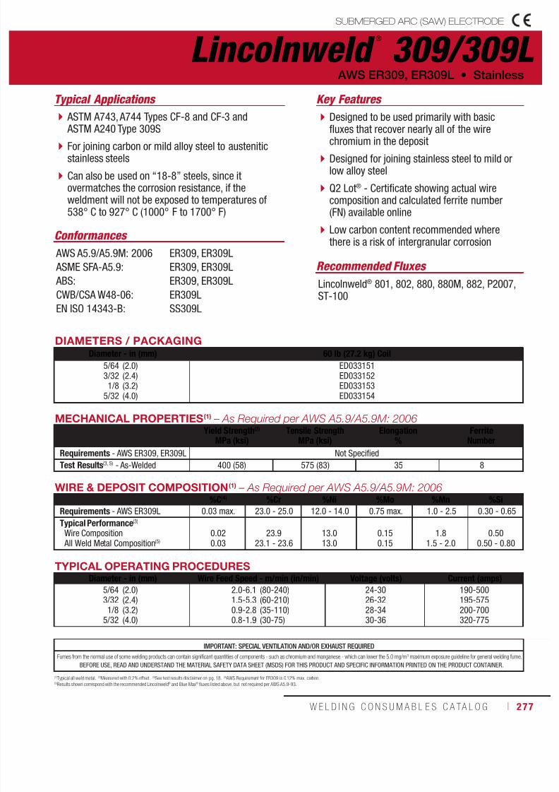
7/18/2019 c110 - Lincoln Electric Consumables 2014
http://slidepdf.com/reader/full/c110-lincoln-electric-consumables-2014 277/511W E L D I N G C O N S U M A B L E S C A TA L O G ı 277
IMPORTANT: SPECIAL VENTILATION AND/OR EXHAUST REQUIRED
Fumes from the normal use of some welding products can contain significant quantities of components - such as chromium and manganese - which can lower the 5.0 mg/m3 maximum exposure guideline for general welding fume.
BEFORE USE, READ AND UNDERSTAND THE MATERIAL SAFETY DATA SHEET (MSDS) FOR THIS PRODUCT AND SPECIFIC INFORMATION PRINTED ON THE PRODUCT CONTAINER.
WIRE & DEPOSIT COMPOSITION(1) – As Required per AWS A5.9/A5.9M: 2006%C(4) %Cr %Ni %Mo %Mn %Si
Requirements - AWS ER309L 0.03 max. 23.0 - 25.0 12.0 - 14.0 0.75 max. 1.0 - 2.5 0.30 - 0.65
Typical Performance(3)
Wire Composition
All Weld Metal Composition(5)
0.02
0.03
23.9
23.1 - 23.6
13.0
13.0
0.15
0.15
1.8
1.5 - 2.0
0.50
0.50 - 0.80
(1)Typical all weld metal. (2)Measured with 0.2% offset. (3)See test results disclaimer on pg. 18. (4) AWS Requirement for ER309 is 0.12% max. carbon.(5)Results shown correspond with the recommended Lincolnweld® and Blue Max® fluxes listed above, but not required per AWS A5.9-93.
TYPICAL OPERATING PROCEDURESDiameter - in (mm) Wire Feed Speed - m/min (in/min) Voltage (volts) Current (amps)
5/643/321/8
5/32
(2.0)(2.4)(3.2)(4.0)
2.0-6.11.5-5.30.9-2.80.8-1.9
(80-240)(60-210)(35-110)(30-75)
24-3026-3228-3430-36
190-500195-575200-700320-775
Lincolnweld ®
309/309LSUBMERGED ARC (SAW) ELECTRODE
Typical Applications
ASTM A743, A744 Types CF-8 and CF-3 and ASTM A240 Type 309S
For joining carbon or mild alloy steel to austeniticstainless steels
Can also be used on “18-8” steels, since itovermatches the corrosion resistance, if theweldment will not be exposed to temperatures of538° C to 927° C (1000° F to 1700° F)
Designed to be used primarily with basicfluxes that recover nearly all of the wirechromium in the deposit
Designed for joining stainless steel to mild orlow alloy steel
Q2 Lot® - Certificate showing actual wirecomposition and calculated ferrite number(FN) available online
Low carbon content recommended wherethere is a risk of intergranular corrosion
Conformances
Recommended Fluxes Lincolnweld® 801, 802, 880, 880M, 882, P2007,ST-100
AWS ER309, ER309L • Stainless
Key Features
AWS A5.9/A5.9M: 2006
ASME SFA-A5.9: ABS:
CWB/CSA W48-06:
EN ISO 14343-B:
ER309, ER309L
ER309, ER309LER309, ER309L
ER309L
SS309L
DIAMETERS / PACKAGINGDiameter - in (mm) 60 lb (27.2 kg) Coil
5/643/321/8
5/32
(2.0)(2.4)(3.2)(4.0)
ED033151ED033152ED033153ED033154
MECHANICAL PROPERTIES(1) – As Required per AWS A5.9/A5.9M: 2006Yield Strength(2)
MPa (ksi)Tensile Strength
MPa (ksi)Elongation
%Ferrite
Number
Requirements - AWS ER309, ER309L Not Specified
Test Results(3, 5) - As-Welded 400 (58) 575 (83) 35 8

7/18/2019 c110 - Lincoln Electric Consumables 2014
http://slidepdf.com/reader/full/c110-lincoln-electric-consumables-2014 278/511278 ı T H E L I N C O L N E L E C T R I C C O M P A N Y
WIRE COMPOSITION(1) – As Required per AWS A5.9/A5.9M: 2006%C(4) %Cr %Ni %Mo %Mn %Si
Requirements - AWS ER316L 0.03 max. 18.0 - 20.0 11.0 - 14.0 2.0 - 3.0 1.0 - 2.5 0.30 - 0.65
Typical Performance(3)
As-Welded
All Weld Metal Composition(5)
0.02
0.02
19.0
17.8 - 18.4
11.9
11.9
2.2
2.2
1.8
1.6 - 2.0
0.50
0.50 - 0.80
(1)Typical all weld metal. (2)Measured with 0.2% offset. (3)See test results disclaimer on pg. 18. (4) AWS Requirement for ER316 is 0.08% max. carbon.(5)Results shown correspond with the recommended Lincolnweld® and Blue Max® fluxes listed above, but not required per AWS A5.9-93.
TYPICAL OPERATING PROCEDURES
Diameter - in (mm) Wire Feed Speed - m/min (in/min) Voltage (volts) Current (amps)
5/64
3/32
1/8
5/32
(2.0)
(2.4)
(3.2)
(4.0)
2.0-6.1
1.5-5.3
0.9-2.8
0.8-1.9
(80-240)
(60-210)
(35-110)
(30-75)
24-30
26-32
28-34
30-36
190-500
195-575
200-700
320-775
Lincolnweld ®
316/316L SUBMERGED ARC (SAW) ELECTRODE
Typical Applications
ASTM A743, A744 Types CF-8 and CF-3
Type 316 and 316L For joining the more common austenitic stainless steelgrades referred to as “18-8” steels
For very good corrosion resistance in acid environments
Designed to be used primarily with basicfluxes that recover nearly all of the wirechromium in the deposit
Molybdenum grade for increased corrosionresistance
Q2 Lot® - Certificate showing actual wirecomposition and calculated ferrite number(FN) available online
Low carbon content recommended wherethere is a risk of intergranular corrosion
Conformances
Recommended Fluxes Lincolnweld® 801, 802, 880, 880M, 882, P2007,ST-100
Stainless • AWS ER316, ER316L
Key Features
AWS A5.9/A5.9M: 2006
ASME SFA-A5.9:
ABS:
CWB/CSA W48-06:EN ISO 14343-B:
ER316, ER316L
ER316, ER316L
ER316, ER316L
ER316LSS316L
DIAMETERS / PACKAGING
Diameter - in (mm) 60 lb (27.2 kg) Coil
5/64
3/32
1/8
5/32
(2.0)
(2.4)
(3.2)
(4.0)
ED033155
ED033156
ED033157
ED033158
MECHANICAL PROPERTIES(1) – As Required per AWS A5.9/A5.9M: 2006Yield Strength(2)
MPa (ksi)Tensile Strength
MPa (ksi)Elongation
%Ferrite
Number
Requirements - AWS ER316, ER316L Not Specified
Test Results(3, 5) - As-Welded 380 (55) 550 (80) 42 9
IMPORTANT: SPECIAL VENTILATION AND/OR EXHAUST REQUIRED
Fumes from the normal use of some welding products can contain significant quantities of components - such as chromium and manganese - which can lower the 5.0 mg/m3 maximum exposure guideline for general welding fume.
BEFORE USE, READ AND UNDERSTAND THE MATERIAL SAFETY DATA SHEET (MSDS) FOR THIS PRODUCT AND SPECIFIC INFORMATION PRINTED ON THE PRODUCT CONTAINER.
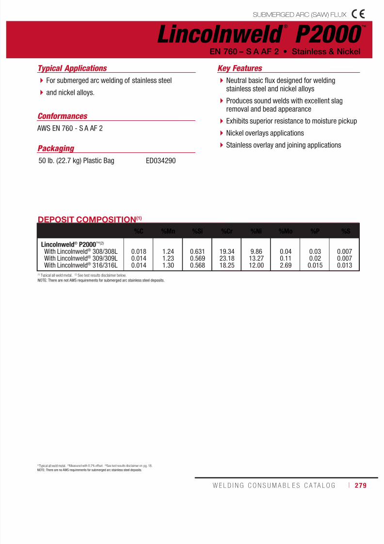
7/18/2019 c110 - Lincoln Electric Consumables 2014
http://slidepdf.com/reader/full/c110-lincoln-electric-consumables-2014 279/511W E L D I N G C O N S U M A B L E S C A TA L O G ı 279
Lincolnweld ®
P2000 ™
SUBMERGED ARC (SAW) FLUX
Typical Applications
For submerged arc welding of stainless steel
and nickel alloys.
Neutral basic flux designed for weldingstainless steel and nickel alloys
Produces sound welds with excellent slagremoval and bead appearance
Exhibits superior resistance to moisture pickup
Nickel overlays applications
Stainless overlay and joining applications
EN 760 – S A AF 2 • Stainless & Nickel
Key Features
(1)Typical all weld metal. (2)Measured with 0.2% offset. (3)See test results disclaimer on pg. 18.NOTE: There are no AWS requirements for submerged arc stainless steel deposits.
Packaging
50 lb. (22.7 kg) Plastic Bag ED034290
Conformances
AWS EN 760 - S A AF 2
DEPOSIT COMPOSITION(1)
%C %Mn %Si %Cr %Ni %Mo %P %S
Lincolnweld® P2000™(2)
With Lincolnweld® 308/308LWith Lincolnweld® 309/309LWith Lincolnweld® 316/316L
0.0180.0140.014
1.241.231.30
0.6310.5690.568
19.3423.1818.25
9.8613.2712.00
0.040.112.69
0.030.020.015
0.0070.0070.013
(1) Typical all weld metal. (2) See test results disclaimer below.
NOTE: There are not AWS requirements for submerged arc stainless steel deposits.

7/18/2019 c110 - Lincoln Electric Consumables 2014
http://slidepdf.com/reader/full/c110-lincoln-electric-consumables-2014 280/511280 ı T H E L I N C O L N E L E C T R I C C O M P A N Y
Lincolnweld ®
P2007 ™
SUBMERGED ARC (SAW) FLUX
Neutral basic flux designed for weldingstainless steel and nickel alloys
Produces sound welds with excellent slagremoval and bead appearance
Exhibits superior resistance to moisture pickup
Nickel overlays applications
Stainless overlay and joining applications
Stainless & Nickel • EN 760 – S A AF 2
Key Features
MECHANICAL PROPERTIES(1)
Yield Strength(2)
MPa (ksi)Tensile Strength
MPa (ksi)Elongation
%Ferrite
Number
Lincolnweld® P2007(3)
With Lincolnweld® 308/308L
With Lincolnweld® 309/309L
With Lincolnweld® 316/316L
380 (55)
400 (58)
380 (55)
565 (82)
570 (83)
550 (80)
42
35
42
10
8
9
DEPOSIT COMPOSITION(1)
%C %Mn %Si %Cr %Ni %Mo %P %S
Lincolnweld® P2007(3)
With Lincolnweld® 308/308L 0.02 1.52 0.63 18.83 9.67 0.13 0.02 0.01With Lincolnweld® 309/309L 0.03 1.71 0.59 23.58 13.35 0.09 0.02 <0.01
With Lincolnweld® 316/316L 0.02 1.36 0.58 18.04 11.50 2.14 0.02 0.01
(1)Typical all weld metal. (2)Measured with 0.2% offset. (3)See test results disclaimer on pg. 18.NOTE: There are no AWS requirements for submerged arc stainless steel deposits.
ED033159
Typical Applications
For submerged arc welding of the 300 and 400series stainless steels, nickel alloys and similaralloy filler metal
Packaging
50 lb (22.7 kg) Plastic Bag
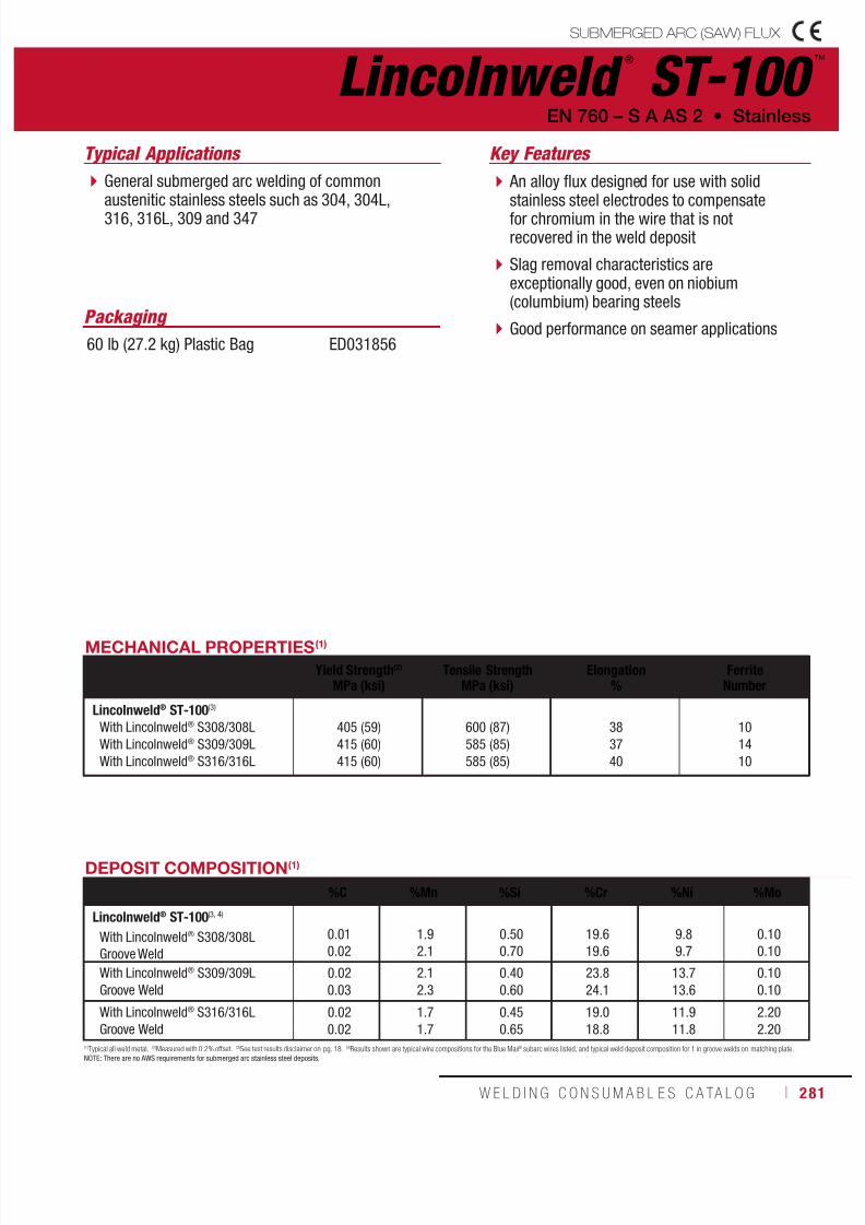
7/18/2019 c110 - Lincoln Electric Consumables 2014
http://slidepdf.com/reader/full/c110-lincoln-electric-consumables-2014 281/511W E L D I N G C O N S U M A B L E S C A TA L O G ı 281
Packaging
60 lb (27.2 kg) Plastic Bag ED031856
Lincolnweld ®
ST-100 ™
SUBMERGED ARC (SAW) FLUX
Typical Applications
General submerged arc welding of commonaustenitic stainless steels such as 304, 304L,316, 316L, 309 and 347
An alloy flux designed for use with solidstainless steel electrodes to compensatefor chromium in the wire that is notrecovered in the weld deposit
Slag removal characteristics areexceptionally good, even on niobium(columbium) bearing steels
Good performance on seamer applications
EN 760 – S A AS 2 • Stainless
Key Features
MECHANICAL PROPERTIES(1)
Yield Strength(2)
MPa (ksi)Tensile Strength
MPa (ksi)Elongation
%Ferrite
Number
Lincolnweld® ST-100(3)
With Lincolnweld® S308/308L
With Lincolnweld® S309/309L
With Lincolnweld® S316/316L
405 (59)
415 (60)
415 (60)
600 (87)
585 (85)
585 (85)
38
37
40
10
14
10
DEPOSIT COMPOSITION(1)
%C %Mn %Si %Cr %Ni %Mo
Lincolnweld® ST-100(3, 4)
With Lincolnweld® S308/308L
Groove Weld
0.01
0.02
1.9
2.1
0.50
0.70
19.6
19.6
9.8
9.7
0.10
0.10
With Lincolnweld® S309/309L
Groove Weld
0.02
0.03
2.1
2.3
0.40
0.60
23.8
24.1
13.7
13.6
0.10
0.10
With Lincolnweld® S316/316L
Groove Weld
0.02
0.02
1.7
1.7
0.45
0.65
19.0
18.8
11.9
11.8
2.20
2.20
(1)Typical all weld metal. (2)Measured with 0.2% offset. (3)See test results disclaimer on pg. 18. (4)Results shown are typical wire compositions for the Blue Max® subarc wires listed, and typical weld deposit composition for 1 in groove welds on matching plate.NOTE: There are no AWS requirements for submerged arc stainless steel deposits.
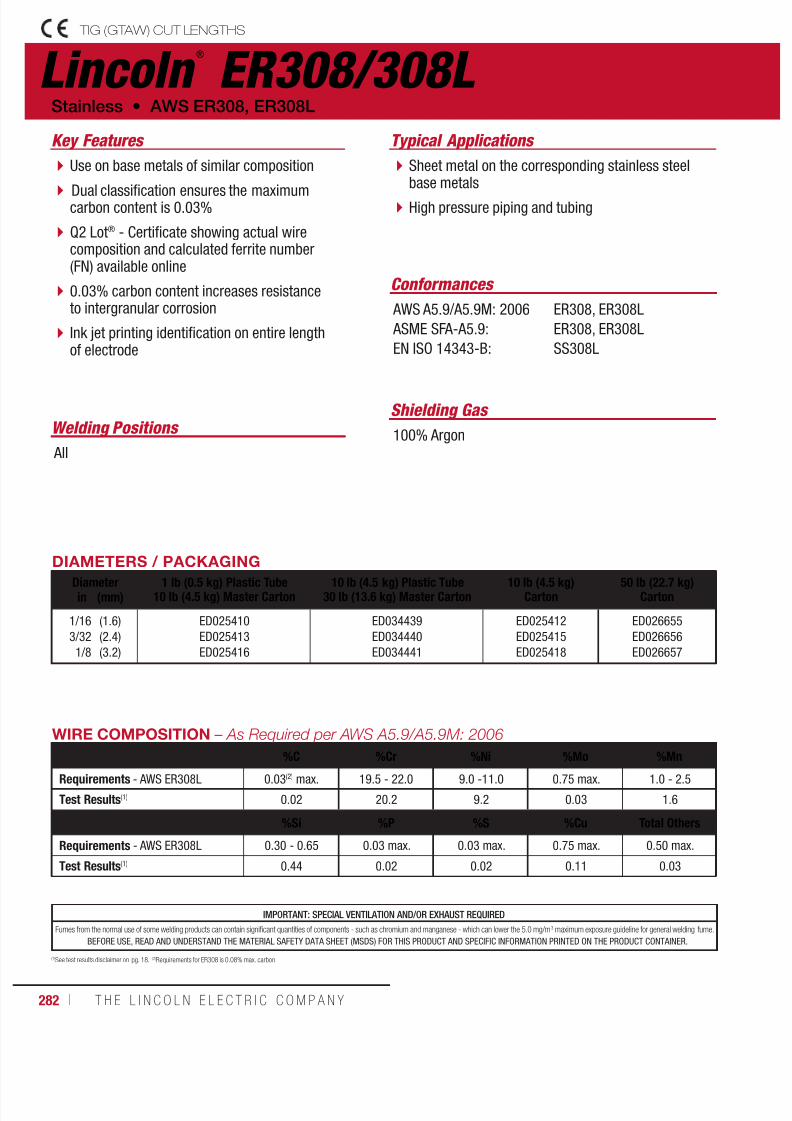
7/18/2019 c110 - Lincoln Electric Consumables 2014
http://slidepdf.com/reader/full/c110-lincoln-electric-consumables-2014 282/511282 ı T H E L I N C O L N E L E C T R I C C O M P A N Y
Lincoln ®
ER308/308L TIG (GTAW) CUT LENGTHS
Welding Positions
Typical Applications
All
Sheet metal on the corresponding stainless steelbase metals
High pressure piping and tubing
Use on base metals of similar composition
Dual classification ensures the maximumcarbon content is 0.03%
Q2 Lot® - Certificate showing actual wirecomposition and calculated ferrite number(FN) available online
0.03% carbon content increases resistanceto intergranular corrosion
Ink jet printing identification on entire lengthof electrode
Conformances
Shielding Gas
100% Argon
Stainless • AWS ER308, ER308L
Key Features
AWS A5.9/A5.9M: 2006
ASME SFA-A5.9:
EN ISO 14343-B:
ER308, ER308L
ER308, ER308L
SS308L
DIAMETERS / PACKAGING
Diameter 1 lb (0.5 kg) Plastic Tube10 lb (4.5 kg) Master Carton
10 lb (4.5 kg) Plastic Tube30 lb (13.6 kg) Master Carton
10 lb (4.5 kg)Carton
50 lb (22.7 kg)Cartonin (mm)
1/16
3/32
1/8
(1.6)
(2.4)
(3.2)
ED025410
ED025413
ED025416
ED034439
ED034440
ED034441
ED025412
ED025415
ED025418
ED026655
ED026656
ED026657
WIRE COMPOSITION – As Required per AWS A5.9/A5.9M: 2006
%C %Cr %Ni %Mo %Mn
Requirements - AWS ER308L 0.03(2) max. 19.5 - 22.0 9.0 -11.0 0.75 max. 1.0 - 2.5
Test Results(1) 0.02 20.2 9.2 0.03 1.6
%Si %P %S %Cu Total Others
Requirements - AWS ER308L 0.30 - 0.65 0.03 max. 0.03 max. 0.75 max. 0.50 max.
Test Results(1) 0.44 0.02 0.02 0.11 0.03
(1)See test results disclaimer on pg. 18. (2)Requirements for ER308 is 0.08% max. carbon.
IMPORTANT: SPECIAL VENTILATION AND/OR EXHAUST REQUIRED
Fumes from the normal use of some welding products can contain significant quantities of components - such as chromium and manganese - which can lower the 5.0 mg/m3 maximum exposure guideline for general welding fume.
BEFORE USE, READ AND UNDERSTAND THE MATERIAL SAFETY DATA SHEET (MSDS) FOR THIS PRODUCT AND SPECIFIC INFORMATION PRINTED ON THE PRODUCT CONTAINER.

7/18/2019 c110 - Lincoln Electric Consumables 2014
http://slidepdf.com/reader/full/c110-lincoln-electric-consumables-2014 283/511W E L D I N G C O N S U M A B L E S C A TA L O G ı 283
Lincoln ®
ER309/309L TIG (GTAW) CUT LENGTHS
Welding Positions
Typical Applications
All
Sheet metal on the corresponding stainless steelbase metals
High pressure piping and tubing
Use for welding dissimilar alloys in wrought orcast form
Occasionally used for welding “18-8” basemetals when severe corrosion conditions existor dissimilar metals
Q2 Lot® - Certificate showing actual wirecomposition and calculated ferrite number(FN) available online
0.03% carbon content increases resistanceto intergranular corrosion
Ink jet printing identification on entire length
of electrode
Conformances
Shielding Gas
100% Argon
AWS ER309, ER309L • Stainless
Key Features
AWS A5.9/A5.9M: 2006
ASME SFA-A5.9:
EN ISO 14343-B:
ER309, ER309L
ER309, ER309L
SS309L
WIRE COMPOSITION – As Required per AWS A5.9/A5.9M: 2006
%C %Cr %Ni %Mo %Mn
Requirements - AWS ER309L 0.03(2) max. 23.0 - 25.0 12.0 - 14.0 0.75 max. 1.0 - 2.5
Test Results(1) 0.02 23.7 13.9 0.04 1.8
%Si %P %S %Cu Total Others
Requirements - AWS ER309L 0.30 - 0.65 0.03 max. 0.03 max. 0.75 max. 0.50 max.
Test Results(1) 0.51 0.02 0.01 0.05 0.06
(1)See test results disclaimer on pg. 18. (2)Requirements for ER309 is 0.12% max. carbon.
IMPORTANT: SPECIAL VENTILATION AND/OR EXHAUST REQUIRED
Fumes from the normal use of some welding products can contain significant quantities of components - such as chromium and manganese - which can lower the 5.0 mg/m3 maximum exposure guideline for general welding fume.
BEFORE USE, READ AND UNDERSTAND THE MATERIAL SAFETY DATA SHEET (MSDS) FOR THIS PRODUCT AND SPECIFIC INFORMATION PRINTED ON THE PRODUCT CONTAINER.
DIAMETERS / PACKAGING
Diameter 1 lb (0.5 kg) Plastic Tube10 lb (4.5 kg) Master Carton
10 lb (4.5 kg) Plastic Tube30 lb (13.6 kg) Master Carton
10 lb (4.5 kg)Carton
50 lb (22.7 kg)Cartonin (mm)
1/16
3/32
1/8
(1.6)
(2.4)
(3.2)
ED025419
ED025422
ED025425
ED034442
ED034443
ED034444
ED025421
ED025424
ED025427
ED026658
ED026659
ED026660
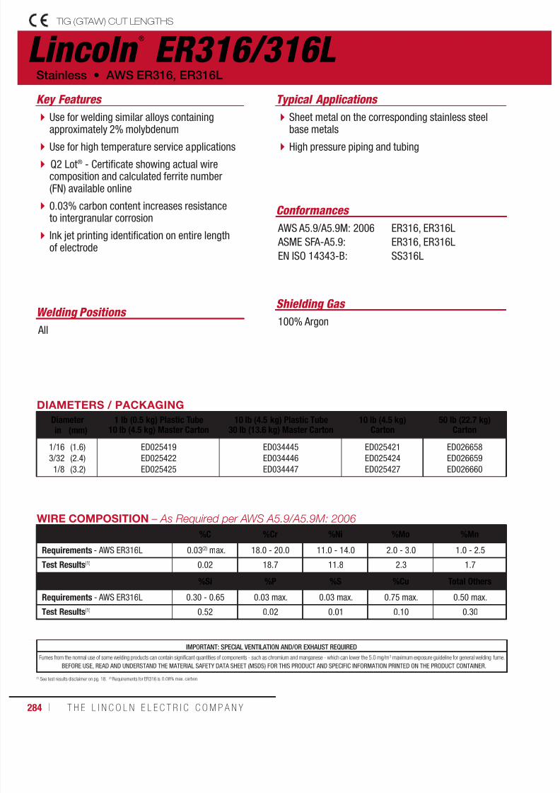
7/18/2019 c110 - Lincoln Electric Consumables 2014
http://slidepdf.com/reader/full/c110-lincoln-electric-consumables-2014 284/511284 ı T H E L I N C O L N E L E C T R I C C O M P A N Y
Lincoln ®
ER316/316L TIG (GTAW) CUT LENGTHS
Welding Positions
Typical Applications
All
Sheet metal on the corresponding stainless steelbase metals
High pressure piping and tubing
Use for welding similar alloys containingapproximately 2% molybdenum
Use for high temperature service applications
Q2 Lot® - Certificate showing actual wirecomposition and calculated ferrite number(FN) available online
0.03% carbon content increases resistanceto intergranular corrosion
Ink jet printing identification on entire lengthof electrode
Conformances
Shielding Gas
100% Argon
Stainless • AWS ER316, ER316L
Key Features
AWS A5.9/A5.9M: 2006
ASME SFA-A5.9:
EN ISO 14343-B:
ER316, ER316L
ER316, ER316L
SS316L
WIRE COMPOSITION – As Required per AWS A5.9/A5.9M: 2006
%C %Cr %Ni %Mo %Mn
Requirements - AWS ER316L 0.03(2) max. 18.0 - 20.0 11.0 - 14.0 2.0 - 3.0 1.0 - 2.5
Test Results(1) 0.02 18.7 11.8 2.3 1.7
%Si %P %S %Cu Total Others
Requirements - AWS ER316L 0.30 - 0.65 0.03 max. 0.03 max. 0.75 max. 0.50 max.
Test Results(1) 0.52 0.02 0.01 0.10 0.30
(1) See test results disclaimer on pg. 18. (2) Requirements for ER316 is 0.08% max. carbon.
IMPORTANT: SPECIAL VENTILATION AND/OR EXHAUST REQUIRED
Fumes from the normal use of some welding products can contain significant quantities of components - such as chromium and manganese - which can lower the 5.0 mg/m3 maximum exposure guideline for general welding fume.
BEFORE USE, READ AND UNDERSTAND THE MATERIAL SAFETY DATA SHEET (MSDS) FOR THIS PRODUCT AND SPECIFIC INFORMATION PRINTED ON THE PRODUCT CONTAINER.
DIAMETERS / PACKAGINGDiameter 1 lb (0.5 kg) Plastic Tube
10 lb (4.5 kg) Master Carton10 lb (4.5 kg) Plastic Tube
30 lb (13.6 kg) Master Carton10 lb (4.5 kg)
Carton50 lb (22.7 kg)
Cartonin (mm)
1/16
3/32
1/8
(1.6)
(2.4)
(3.2)
ED025419
ED025422
ED025425
ED034445
ED034446
ED034447
ED025421
ED025424
ED025427
ED026658
ED026659
ED026660
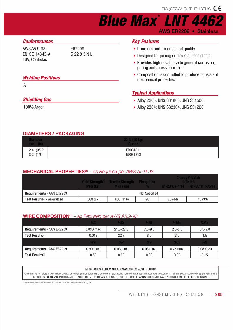
7/18/2019 c110 - Lincoln Electric Consumables 2014
http://slidepdf.com/reader/full/c110-lincoln-electric-consumables-2014 285/511W E L D I N G C O N S U M A B L E S C A TA L O G ı 285
(1)Typical all weld metal. (2)Measured with 0.2% offset. (3)See test results disclaimer on pg. 18.
Blue Max ®
LNT 4462 TIG (GTAW) CUT LENGTHS
AWS ER2209 • Stainless
DIAMETERS / PACKAGING
Diameter 22 lb (10 kg)Cartonmm (in)
2.4
3.2
(3/32)
(1/8)
ED031311
ED031312
MECHANICAL PROPERTIES(1) – As Required per AWS A5.9-93
Yield Strength(2)
Tensile Strength
Elongation
Charpy V-NotchJ (ft•lbf)
MPa (ksi) MPa (ksi) % @ -20°C (-4°F) @ -60°C (-75°F)
Requirements - AWS ER2209 Not Specified
Test Results(2) - As-Welded 600 (87) 800 (116) 28 60 (44) 45 (33)
IMPORTANT: SPECIAL VENTILATION AND/OR EXHAUST REQUIRED
Fumes from the normal use of some welding products can contain significant quantities of components - such as chromium and manganese - which can lower the 5.0 mg/m3 maximum exposure guideline for general welding fume.
BEFORE USE, READ AND UNDERSTAND THE MATERIAL SAFETY DATA SHEET (MSDS) FOR THIS PRODUCT AND SPECIFIC INFORMATION PRINTED ON THE PRODUCT CONTAINER.
Welding Positions
Typical Applications
All
Alloy 2205: UNS S31803, UNS S31500
Alloy 2304: UNS S32304, UNS S31200
Premium performance and quality
Designed for joining duplex stainless steels Provides high resistance to general corrosion,pitting and stress corrosion
Composition is controlled to produce consistentmechanical properties
Conformances
Shielding Gas
100% Argon
Key Features
AWS A5.9-93:
EN ISO 14343-A:TUV, Controlas
ER2209
G 22 9 3 N L
WIRE COMPOSITION(1) – As Required per AWS A5.9-93
%C %Cr %Ni %Mo %Mn
Requirements - AWS ER2209 0.030 max. 21.5-23.5 7.5-9.5 2.5-3.5 0.5-2.0
Test Results(3) 0.018 22.7 8.5 3.0 1.5
%Si %P %S %Cu %N
Requirements - AWS ER2209 0.90 max. 0.03 max. 0.03 max. 0.75 max. 0.08-0.20
Test Results(3) 0.50 0.03 0.03 0.30 0.15
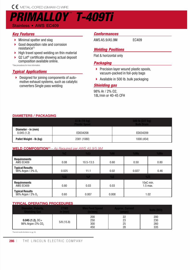
7/18/2019 c110 - Lincoln Electric Consumables 2014
http://slidepdf.com/reader/full/c110-lincoln-electric-consumables-2014 286/511286 ı T H E L I N C O L N E L E C T R I C C O M P A N Y
PRIMALLOY ™
T-409Ti METAL-CORED (GMAW-C) WIRE
Stainless • AWS EC409
Typical Applications
Key Features
Minimal spatter and slag
Good deposition rate and corrosionresistance(1)
High travel speed welding on thin material
Q2 Lot® certificate showing actual depositcomposition available online.
Designed for joining components of auto-motive exhaust systems, such as catalyticconverters Single pass welding
(1)See procedures for more information.
DIAMETERS / PACKAGING
33 lb (15 kg)Plastic Spool
500 lb (227 kg)Bulk Drum
Diameter - in (mm)0.045 (1.2) ED034208 ED034209
Pallet Weight - lb (kg) 2381 (1080) 1000 (454)
TYPICAL OPERATING PROCEDURES
Diameter, Polarity,Shielding Gas
CTWDin (mm)
Wire Feed Speed(in/mm)
Approx. Current(amps)
Volts (DCt)
0.045 (1.2), DC+98% Argon /2% CO2
5/8 (15.8)
200250300450
22232528
200230260335
WELD COMPOSITION(1) – As Required per AWS A5.9/5.9M
%C %Cr %Ni %Mo %Mn
Requirements AWS EC409 0.08 10.5-13.5 0.60
0.50 0.80
Typical Results98% Argon / 2% O2 0.025 11.1 0.02 0.027 0.46
%Si %P %S %Ti
Requirements AWS EC409 0.80 0.03 0.03
10xC min.1.5 max.
Typical Results98% Argon / 2% O2 0.60 0.007 0.008 1.02
Packaging
Welding Positions
Shielding gas
Conformances
Precision layer wound plastic spools,vacuum-packed in foil-poly bags
Available in 500 lb. bulk packaging
AWS A5.9/A5.9M EC409
Flat & horizontal only
98% Ar / 2% O2,18L/min or 40-45 CFH
(1)See test results disclaimer on pg. 18.

7/18/2019 c110 - Lincoln Electric Consumables 2014
http://slidepdf.com/reader/full/c110-lincoln-electric-consumables-2014 287/511W E L D I N G C O N S U M A B L E S C A TA L O G ı 287
PRIMALLOY ™
T-439Ti METAL-CORED (GMAW-C) WIRE
AWS EC409 • Stainless
Packaging
Welding Positions
Conformances
Precision layer wound plastic spools,vacuum-packed in foil-poly bags
Available in 500 lb. bulk packaging
AWS A5.9/A5.9M EC439
Flat & horizontal only
Shielding gas
98% Ar / 2% O2,18L/min or 40-45 CFH
TYPICAL OPERATING PROCEDURES
Diameter, Polarity,Shielding Gas
CTWDin (mm)
Wire Feed Speed(in/min)
Approx. Current(amps)
Volts(DCt)
0.045 (1.2), DC+98% Argon /2% CO2
5/8 (15.8)
200250300450
22232528
200230260335
WELD COMPOSITION(1) – As Required per AWS A5.9/5.9M
%C %Cr %Ni %Mo %Mn
Requirements AWS EC439 0.04 17.0-19.0 0.60
0.50 0.80
Typical Results98% Argon / 2% O2 0.027 17.43 0.017 0.015 0.47
%Si %P %S %Ti
Requirements
AWS EC439 0.80 0.03 0.03
10xC min.
1.5 max.Typical Results
98% Argon / 2% O2 0.38 0.007 0.011 0.284
DIAMETERS / PACKAGING
33 lb (15 kg)Plastic Spool
500 lb (227 kg)Bulk Drum
Diameter - in (mm)0.045 (1.2) ED034293 ED034294
Pallet Weight - lb (kg) 2381 (1080) 1000 (454)
Typical Applications
Key Features
Minimal spatter and slag
Good deposition rate and corrosionresistance(1)
High travel speed welding on thin material
Q2 Lot® certificate showing actual depositcomposition available online
Designed for joining components ofautomotive exhaust systems, such ascatalytic converters
Single pass welding
(1)See procedures for more information.
(1)See test results disclaimer on pg. 18.
7/18/2019 c110 - Lincoln Electric Consumables 2014
http://slidepdf.com/reader/full/c110-lincoln-electric-consumables-2014 288/511288 ı T H E L I N C O L N E L E C T R I C C O M P A N Y
Notes STAINLESS WELDING CONSUMABLES

7/18/2019 c110 - Lincoln Electric Consumables 2014
http://slidepdf.com/reader/full/c110-lincoln-electric-consumables-2014 289/511W E L D I N G C O N S U M A B L E S C A TA L O G ı 289
SMAW CONSUMABLES
NICKELStick ElectrodeTech-Rod® 55 ............................................. 290Tech-Rod® 99 .............................................. 291
Tech-Rod®
112 ............................................ 292Tech-Rod® 112LFe ....................................... 293Tech-Rod® 117 ............................................ 294Tech-Rod® 122 ............................................ 295Tech-Rod® 141 ............................................ 296Tech-Rod® 182 ............................................ 297Tech-Rod® 187 ............................................ 298Tech-Rod® 190 ............................................ 299Tech-Rod® 276 ............................................ 300Tech-Rod® Weld A ........................................ 301
MIG WireTechalloy® 55 ............................................... 302Techalloy® 99 ............................................... 303Techalloy® 208 ............................................. 304Techalloy® 276 ............................................. 305Techalloy® 413 ............................................. 306Techalloy® 418 ............................................. 307Techalloy® 606 ............................................. 308Techalloy® 617 ............................................. 309Techalloy® 622 ............................................. 310Techalloy® 625 ............................................. 311Techalloy® 718 ............................................. 312
Techalloy® 825 ............................................. 313
Flux-Cored (FCAW-G) WireSuperCore® 625P ......................................... 314
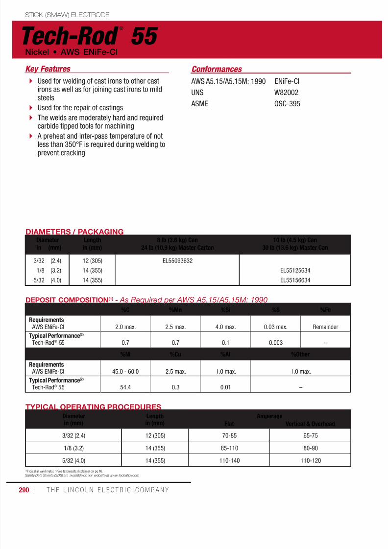
7/18/2019 c110 - Lincoln Electric Consumables 2014
http://slidepdf.com/reader/full/c110-lincoln-electric-consumables-2014 290/511290 ı T H E L I N C O L N E L E C T R I C C O M P A N Y
STICK (SMAW) ELECTRODE
Tech-Rod ®
55Key Features
Used for welding of cast irons to other castirons as well as for joining cast irons to mildsteels
Used for the repair of castings
The welds are moderately hard and requiredcarbide tipped tools for machining
A preheat and inter-pass temperature of notless than 350°F is required during welding toprevent cracking
(1)Typical all weld metal. (2)See test results disclaimer on pg 16.
Safety Data Sheets (SDS) are available on our website at www.techalloy.com
AWS A5.15/A5.15M: 1990 ENiFe-Cl
UNS W82002 ASME QSC-395
Conformances
DIAMETERS / PACKAGINGDiameter Length
in (mm)8 lb (3.6 kg) Can
24 lb (10.9 kg) Master Carton10 lb (4.5 kg) Can
30 lb (13.6 kg) Master Canin (mm)
3/32
1/8
5/32
(2.4)
(3.2)
(4.0)
12 (305)
14 (355)
14 (355)
EL55093632
EL55125634
EL55156634
TYPICAL OPERATING PROCEDURESDiameterin (mm)
Lengthin (mm)
AmperageFlat Vertical & Overhead
3/32 (2.4) 12 (305) 70-85 65-75
1/8 (3.2) 14 (355) 85-110 80-90
5/32 (4.0) 14 (355) 110-140 110-120
DEPOSIT COMPOSITION(1) - As Required per AWS A5.15/A5.15M: 1990
%C %Mn %Si %S %Fe
Requirements AWS ENiFe-Cl 2.0 max. 2.5 max. 4.0 max. 0.03 max. Remainder
Typical Performance(2)
Tech-Rod® 55 0.7 0.7 0.1 0.003 –
%Ni %Cu %Al %Other
Requirements AWS ENiFe-Cl 45.0 - 60.0 2.5 max. 1.0 max. 1.0 max.
Typical Performance(2)
Tech-Rod® 55 54.4 0.3 0.01 –
Nickel • AWS ENiFe-Cl

7/18/2019 c110 - Lincoln Electric Consumables 2014
http://slidepdf.com/reader/full/c110-lincoln-electric-consumables-2014 291/511W E L D I N G C O N S U M A B L E S C A TA L O G ı 291
STICK (SMAW) ELECTRODE
Tech-Rod ®
99
AWS A5.15/A5.15M: 1990 ENi-Cl
UNS W82001 ASME QSC-395
DIAMETERS / PACKAGINGDiameter Length
in (mm)8 lb (3.6 kg) Can
24 lb (10.9 kg) Master Carton10 lb (4.5 kg) Can
30 lb (13.6 kg) Master Canin (mm)
3/32
1/8
5/32
(2.4)
(3.2)
(4.0)
12 (305)
14 (355)
14 (355)
EL99093632
EL99125634
EL99156634
AWS ENi-Cl • Nickel
TYPICAL OPERATING PROCEDURESDiameterin (mm)
Lengthin (mm)
AmperageFlat Vertical & Overhead
3/32 (2.4) 12 (305) 70-85 65-75
1/8 (3.2) 14 (355) 85-110 80-90
5/32 (4.0) 14 (355) 110-140 110-120
DEPOSIT COMPOSITION(1) - As Required per AWS A5.15/A5.15M: 1990
%C %Mn %Si %S %Fe
Requirements AWS ENi-Cl 2.0 max. 2.5 max. 4.0 max. 0.03 max. 8.0 max.
Typcial Performance(2)
Tech-Rod® 99 0.5 0.1 0.2 0.002 1.2
%Ni %Cu %Al %Other
Requirements AWS ENi-Cl 85.0 min 2.5 max. 1.0 max. 1.0 max.
Typcial Performance(2)
Tech-Rod® 99 97.5 0.2 0.06 1.0 max.
Used for welding of cast irons to other castirons as well as for joining cast irons to mildsteels and stainless steels
Readily used for the repair of castings
The welds produced are generally moremachinable than a Tech-Rod® 55 deposit
A preheat and inter-pass temperature of notless than 350°F is required during welding toprevent cracking
(1)Typical all weld metal. (2)See test results disclaimer on pg. 18.Safety Data Sheets (SDS) are available on our website at www.techalloy.com
Conformances Key Features

7/18/2019 c110 - Lincoln Electric Consumables 2014
http://slidepdf.com/reader/full/c110-lincoln-electric-consumables-2014 292/511292 ı T H E L I N C O L N E L E C T R I C C O M P A N Y
STICK (SMAW) ELECTRODE
Tech-Rod ®
112Nickel • AWS ENiCrMo-3
AWS A5.11/A5.11M: 2010 ENiCrMo-3
UNS W86112 ASME QSC-395
DIAMETERS / PACKAGINGDiameter Length
in (mm)8 lb (3.6 kg) Can
24 lb (10.9 kg) Master Carton10 lb (4.5 kg) Can
30 lb (13.6 kg) Master Canin (mm)
3/32
1/8
5/32
3/16
(2.4)
(3.2)
(4.0)
(4.8)
12 (305)
14 (355)
14 (355)
14 (355)
EL112093632
EL112125634
EL112156634
EL112187634
TYPICAL OPERATING PROCEDURESDiameterin (mm)
Lengthin (mm)
AmperageFlat Vertical & Overhead
3/32 (2.4) 12 (305) 70-85 65-75
1/8 (3.2) 14 (355) 85-110 80-90
5/32 (4.0) 14 (355) 110-140 110-120
3/16 (4.8) 14 (355) 120-160 110-130
DEPOSIT COMPOSITION(1) - As Required per AWS A5.11: 2010
%C %Mn %Fe %P %S %Si
Requirements AWS ENiCrMo-3 0.10 max. 1.0 max. 7.0 max. 0.03 max. 0.02 max. 0.75 max.
Typcial Performance(2)
Tech-Rod® 112 0.03 0.3 1.9 0.01 0.003 0.33
%Ni %Cr %Nb+Ta %Mo %Other
Requirements AWS ENiCrMo-3 55.0 min. 20.0 - 23.0 3.15 - 4.15 8.0 - 10.0 0.50 max.
Typcial Performance(2)
Tech-Rod®
112 62.1 22.4 3.63 8.7 –
A covered electrode which is used to weldnickel-chromium-molybdenum alloys.
Used extensively in overlay cladding wherea similar chemical composition is requiredon the clad side
Dissimilar joints between nickel-chromium-molybdenum alloys to stainless steels,carbon or low alloy steels
These electrodes are used in applicationswhere the temperature ranges fromcryogenic up to 1800°F (982°C)
(1)Typical all weld metal. (2)See test results disclaimer on pg. 18.
Safety Data Sheets (SDS) are available on our website at www.techalloy.com
Conformances Key Features

7/18/2019 c110 - Lincoln Electric Consumables 2014
http://slidepdf.com/reader/full/c110-lincoln-electric-consumables-2014 293/511W E L D I N G C O N S U M A B L E S C A TA L O G ı 293
STICK (SMAW) ELECTRODE
Tech-Rod ®
112LFe AWS ENiCrMo-3 • Nickel
AWS A5.11/A5.11M: 2010 ENiCrMo-3
UNS W86112 ASME QSC-395
DIAMETERS / PACKAGINGDiameter Length
in (mm)10 lb (4.5 kg) Can
30 lb (13.6 kg) Master Canin (mm)
1/8
5/32
3/16
(3.2)
(4.0)
(4.8)
14 (355)
14 (355)
14 (355)
EL112LFE125634
EL112LFE156634
EL112LFE187634
TYPICAL OPERATING PROCEDURESDiameterin (mm)
Lengthin (mm)
AmperageFlat Vertical & Overhead
1/8 (3.2) 14 (355) 85-110 80-90
5/32 (4.0) 14 (355) 110-140 110-120
3/16 (4.8) 14 (355) 120-160 110-130
DEPOSIT COMPOSITION(1) - As Required per AWS A5.11: 2010
%C %Mn %Fe %P %S %Si
Requirements AWS ENiCrMo-3 0.10 max. 1.0 max. 7.0 max. 0.03 0.02 max. 0.75 max.
Typcial Performance(2)
Tech-Rod® 112LFe 0.02 0.2 0.8 0.01 0.003 0.27
%Cu %Ni %Cr %Nb+Ta %Mo %Other
Requirements AWS ENiCrMo-3 0.50 max. 55.00 min. 20.0 - 23.0 3.15 - 4.15 8.0 - 10.0 0.50 max.
Typcial Performance(2)
Tech-Rod® 112LFe 0.02 63.8 22.5 3.6 8.7 –
(1)Typical all weld metal. (2)See test results disclaimer on pg. 18.
Safety Data Sheets (SDS) are available on our website at www.techalloy.com
A low iron version of the standard Tech-Rod® 112 covered electrode which is used to weldnickel-chromium-molybdenum alloys
The product is designed to have less than 1%Iron (Fe) for overlay applications to minimizedilution of parent metal iron in the deposit
Conformances Key Features
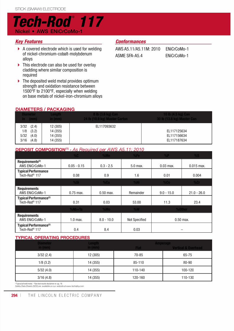
7/18/2019 c110 - Lincoln Electric Consumables 2014
http://slidepdf.com/reader/full/c110-lincoln-electric-consumables-2014 294/511294 ı T H E L I N C O L N E L E C T R I C C O M P A N Y
STICK (SMAW) ELECTRODE
Tech-Rod ®
117 Nickel • AWS ENiCrCoMo-1
TYPICAL OPERATING PROCEDURES
Diameterin (mm)
Lengthin (mm)
AmperageFlat Vertical & Overhead
3/32 (2.4) 12 (305) 70-85 65-75
1/8 (3.2) 14 (355) 85-110 80-90
5/32 (4.0) 14 (355) 110-140 100-120
3/16 (4.8) 14 (355) 120-160 110-130
DEPOSIT COMPOSITION(1) - As Required per AWS A5.11: 2010
%C %Mn %Fe %P %S
Requirements(2)
AWS ENiCrCoMo-1 0.05 - 0.15 0.3 - 2.5 5.0 max. 0.03 max. 0.015 max.
Typical PerformanceTech-Rod® 117 0.08 0.9 1.6 0.01 0.004
%Si %Cu %Ni %Co %Cr
Requirements AWS ENiCrCoMo-1 0.75 max. 0.50 max. Remainder 9.0 - 15.0 21.0 - 26.0
Typical Performance(2)
Tech-Rod® 117 0.31 0.03 53.00 11.3 23.4
%Nb+Ta %Mo %W %Other
Requirements AWS ENiCrCoMo-1 1.0 max. 8.0 - 10.0 Not Specified 0.50 max.
Typical Performance(2)
Tech-Rod® 117 0.4 8.4 0.03 –
AWS A5.11/A5.11M: 2010 ENiCrCoMo-1
ASME SFA-A5.4 ENiCrCoMo-1
DIAMETERS / PACKAGING
Diameter Lengthin (mm)
8 lb (3.6 kg) Can24 lb (10.9 kg) Master Carton
10 lb (4.5 kg) Can30 lb (13.6 kg) Master Canin (mm)
3/32
1/8
5/32
3/16
(2.4)
(3.2)
(4.0)
(4.8)
12 (305)
14 (355)
14 (355)
14 (355)
EL117093632
EL117125634
EL117156634
EL117187634
(1)Typical all weld metal. (2)See test results disclaimer on pg. 18.Safety Data Sheets (SDS) are available on our website at www.techalloy.com
A covered electrode which is used for weldingof nickel-chromium-cobalt-molybdenumalloys
This electrode can also be used for overlaycladding where similar composition isrequired
The deposited weld metal provides optimumstrength and oxidation resistance between1500°F to 2100°F, especially when weldingon base metals of nickel-iron-chromium alloys
Conformances Key Features
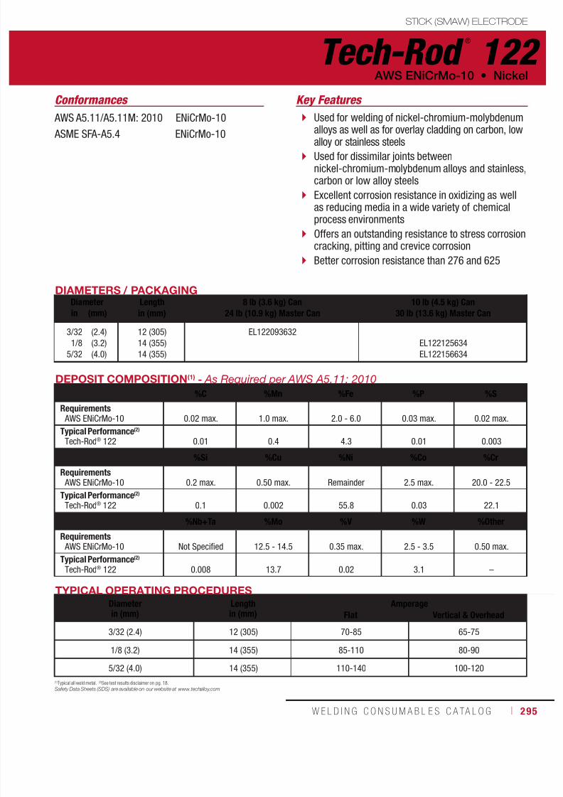
7/18/2019 c110 - Lincoln Electric Consumables 2014
http://slidepdf.com/reader/full/c110-lincoln-electric-consumables-2014 295/511W E L D I N G C O N S U M A B L E S C A TA L O G ı 295
STICK (SMAW) ELECTRODE
Tech-Rod ®
122 AWS ENiCrMo-10 • Nickel
AWS A5.11/A5.11M: 2010 ENiCrMo-10
ASME SFA-A5.4 ENiCrMo-10
DIAMETERS / PACKAGINGDiameter Length
in (mm)8 lb (3.6 kg) Can
24 lb (10.9 kg) Master Can10 lb (4.5 kg) Can
30 lb (13.6 kg) Master Canin (mm)
3/32
1/8
5/32
(2.4)
(3.2)
(4.0)
12 (305)
14 (355)
14 (355)
EL122093632
EL122125634
EL122156634
TYPICAL OPERATING PROCEDURESDiameterin (mm)
Lengthin (mm)
AmperageFlat Vertical & Overhead
3/32 (2.4) 12 (305) 70-85 65-75
1/8 (3.2) 14 (355) 85-110 80-90
5/32 (4.0) 14 (355) 110-140 100-120
DEPOSIT COMPOSITION(1) - As Required per AWS A5.11: 2010
%C %Mn %Fe %P %S
Requirements AWS ENiCrMo-10 0.02 max. 1.0 max. 2.0 - 6.0 0.03 max. 0.02 max.
Typical Performance(2)
Tech-Rod® 122 0.01 0.4 4.3 0.01 0.003
%Si %Cu %Ni %Co %Cr
Requirements AWS ENiCrMo-10 0.2 max. 0.50 max. Remainder 2.5 max. 20.0 - 22.5
Typical Performance(2)
Tech-Rod® 122 0.1 0.002 55.8 0.03 22.1
%Nb+Ta %Mo %V %W %Other
Requirements
AWS ENiCrMo-10 Not Specified 12.5 - 14.5 0.35 max. 2.5 - 3.5 0.50 max.Typical Performance(2)
Tech-Rod® 122 0.008 13.7 0.02 3.1 –
(1)Typical all weld metal. (2)See test results disclaimer on pg. 18.Safety Data Sheets (SDS) are available on our website at www.techalloy.com
Used for welding of nickel-chromium-molybdenumalloys as well as for overlay cladding on carbon, lowalloy or stainless steels
Used for dissimilar joints betweennickel-chromium-molybdenum alloys and stainless,carbon or low alloy steels
Excellent corrosion resistance in oxidizing as wellas reducing media in a wide variety of chemicalprocess environments
Offers an outstanding resistance to stress corrosioncracking, pitting and crevice corrosion
Better corrosion resistance than 276 and 625
Conformances Key Features

7/18/2019 c110 - Lincoln Electric Consumables 2014
http://slidepdf.com/reader/full/c110-lincoln-electric-consumables-2014 296/511296 ı T H E L I N C O L N E L E C T R I C C O M P A N Y
STICK (SMAW) ELECTRODE
Tech-Rod ®
141Nickel • AWS ENi-1
TYPICAL OPERATING PROCEDURES
Diameterin (mm)
Lengthin (mm)
AmperageFlat Vertical & Overhead
3/32 (2.4) 12 (305) 70-85 65-75
1/8 (3.2) 14 (355) 85-110 80-90
5/32 (4.0) 14 (355) 110-140 100-120
3/16 (4.8) 14 (355) 120-160 110-130
DEPOSIT COMPOSITION(1) - As Required per AWS A5.11/A5.11M: 2010
%C %Mn %Fe %P %S %Si
Requirements AWS ENi-1 0.10 max. 0.75 max. 0.75 max. 0.03 max. 0.02 max. 1.25 max.
Typical Performance(2)
Tech-Rod® 141 0.02 0.43 0.52 0.01 0.01 0.93
%Cu %Ni %Ti %Al %Other
Requirements AWS ENi-1 0.25 max. 92.0 min. 1.0 - 4.0 1.0 max. 0.50 max.
Typical Performance(2)
Tech-Rod® 141 0.04 96.7 1.2 0.03 –
AWS A5.11/A5.11M: 2010 ENi-1
ASME SFA-A5.4 ENi-1
DIAMETERS / PACKAGINGDiameter Length
in (mm)8 lb (3.6 kg) Can
24 lb (10.9 kg) Master Carton10 lb (4.5 kg) Can
30 lb (13.6 kg) Master Canin (mm)
3/32
1/8
5/32
3/16
(2.4)
(3.2)
(4.0)
(4.8)
12 (305)
14 (355)
14 (355)
14 (355)
EL141093632
EL141125634
EL141156634
EL141187634
(1)Typical all weld metal. (2)See test results disclaimer on pg. 18.
Safety Data Sheets (SDS) are available on our website at www.techalloy.com
Welding of cast and wrought forms of purenickel alloys
Used for surfacing as well as dissimilarwelding between nickel or mild steel andstainless steel
Conformances Key Features
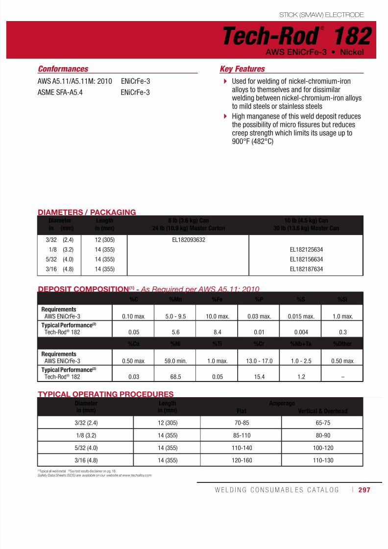
7/18/2019 c110 - Lincoln Electric Consumables 2014
http://slidepdf.com/reader/full/c110-lincoln-electric-consumables-2014 297/511W E L D I N G C O N S U M A B L E S C A TA L O G ı 297
STICK (SMAW) ELECTRODE
Tech-Rod ®
182 AWS ENiCrFe-3 • Nickel
AWS A5.11/A5.11M: 2010 ENiCrFe-3
ASME SFA-A5.4 ENiCrFe-3
Conformances
DIAMETERS / PACKAGINGDiameter Length
in (mm)8 lb (3.6 kg) Can
24 lb (10.9 kg) Master Carton10 lb (4.5 kg) Can
30 lb (13.6 kg) Master Canin (mm)
3/32
1/8
5/32
3/16
(2.4)
(3.2)
(4.0)
(4.8)
12 (305)
14 (355)
14 (355)
14 (355)
EL182093632
EL182125634
EL182156634
EL182187634
TYPICAL OPERATING PROCEDURESDiameterin (mm)
Lengthin (mm)
AmperageFlat Vertical & Overhead
3/32 (2.4) 12 (305) 70-85 65-75
1/8 (3.2) 14 (355) 85-110 80-90
5/32 (4.0) 14 (355) 110-140 100-120
3/16 (4.8) 14 (355) 120-160 110-130
DEPOSIT COMPOSITION(1) - As Required per AWS A5.11: 2010
%C %Mn %Fe %P %S %Si
Requirements AWS ENiCrFe-3 0.10 max. 5.0 - 9.5 10.0 max. 0.03 max. 0.015 max. 1.0 max.
Typical Performance(2)
Tech-Rod® 182 0.05 5.6 8.4 0.01 0.004 0.3
%Cu %Ni %Ti %Cr %Nb+Ta %Other
Requirements AWS ENiCrFe-3 0.50 max. 59.0 min. 1.0 max. 13.0 - 17.0 1.0 - 2.5 0.50 max.
Typical Performance(2)
Tech-Rod® 182 0.03 68.5 0.05 15.4 1.2 –
(1)Typical all weld metal. (2)See test results disclaimer on pg. 18.
Safety Data Sheets (SDS) are available on our website at www.techalloy.com
Used for welding of nickel-chromium-ironalloys to themselves and for dissimilarwelding between nickel-chromium-iron alloysto mild steels or stainless steels
High manganese of this weld deposit reducesthe possibility of micro fissures but reducescreep strength which limits its usage up to900°F (482°C)
Key Features

7/18/2019 c110 - Lincoln Electric Consumables 2014
http://slidepdf.com/reader/full/c110-lincoln-electric-consumables-2014 298/511298 ı T H E L I N C O L N E L E C T R I C C O M P A N Y
STICK (SMAW) ELECTRODE
Tech-Rod ®
187 Nickel • AWS ECuNi
AWS A5.6/A5.6M: 2008 ECuNi
ASME SFA-A5.4 ECuNi
Conformances
DIAMETERS / PACKAGINGDiameter Length
in (mm)8 lb (3.6 kg) Can
24 lb (10.9 kg) Master Carton10 lb (4.5 kg) Can
30 lb (13.6 kg) Master Canin (mm)
3/32
1/8
(2.4)
(3.2)
12 (305)
14 (355)
EL187093632
EL187125634
TYPICAL OPERATING PROCEDURESDiameterin (mm)
Lengthin (mm)
AmperageFlat Vertical & Overhead
3/32 (2.4) 12 (305) 70-85 65-75
1/8 (3.2) 14 (355) 85-110 80-90
DEPOSIT COMPOSITION(1) - As Required per AWS A5.6: 2008
%Mn %Fe %P %Si %Cu
Requirements AWS ECuNi 1.00 - 2.50 0.40 - 0.75 0.020 max. 0.50 max. Remainder
Typical Performance(2)
Tech-Rod® 187 1.19 0.50 0.005 0.01 67.0
%Ni %Ti %Pb %Other
Requirements AWS ECuNi 29.0 - 33.0 0.50 max. 0.02 max. 0.50 max.
Typical Performance(2)
Tech-Rod® 187 31.0 0.24 0.003 –
(1)Typical all weld metal. (2)See test results disclaimer on pg. 18.
Safety Data Sheets (SDS) are available on our website at www.techalloy.com
A copper-nickel electrode for shielded metaland welding of wrought of cast alloys ofsimilar composition as well as 80/20 and90/10 Cu/Ni alloys
Used for the clad side of copper-nickel cladsteels
This filler metal is widely used in marineapplications because of its good resistanceto the corrosive effects of sea water
Key Features

7/18/2019 c110 - Lincoln Electric Consumables 2014
http://slidepdf.com/reader/full/c110-lincoln-electric-consumables-2014 299/511W E L D I N G C O N S U M A B L E S C A TA L O G ı 299
STICK (SMAW) ELECTRODE
Tech-Rod ®
190 AWS ENiCu-7 • Nickel
AWS A5.11/A5.11M: 2010 ENiCu-7
ASME SFA-A5.4 ENiCu-7
Conformances
DIAMETERS / PACKAGINGDiameter Length
in (mm)8 lb (3.6 kg) Can
24 lb (10.9 kg) Master Carton10 lb (4.5 kg) Can
30 lb (13.6 kg) Master Canin (mm)
3/32
1/8
5/32
3/16
(2.4)
(3.2)
(4.0)
(4.8)
12 (305)
14 (355)
14 (355)
14 (355)
EL190093632
EL190125634
EL190156634
EL190187634
TYPICAL OPERATING PROCEDURESDiameterin (mm)
Lengthin (mm)
AmperageFlat Vertical & Overhead
3/32 (2.4) 12 (305) 70-85 65-75
1/8 (3.2) 14 (355) 85-110 80-90
5/32 (4.0) 14 (355) 110-140 100-120
3/16 (4.8) 14 (355) 120-160 110-130
DEPOSIT COMPOSITION(1) - As Required per AWS A5.11/A5.11M: 2010
%C %Mn %Fe %P %S %Si
Requirements AWS ENiCu-7 0.15 4.0 max. 2.5 max. 0.02 max. 0.015 max. 1.5 max.
Typcial Performance(2)
Tech-Rod® 190 0.03 3.1 0.9 0.01 0.004 0.61
%Cu %Ni %Al %Ti %Other
Requirements AWS ENiCu-7 Remainder 62 - 69 0.75 max. 1.0 max. 1.0 max.
Typcial Performance(2)
Tech-Rod® 190 27 65 0.05 0.21 –
(1)Typical all weld metal. (2)See test results disclaimer on pg. 18.
Safety Data Sheets (SDS) are available on our website at www.techalloy.com
Welding nickel-copper alloys to themselvesand to steel
Used for overlay welding as well as forwelding of clad steels where nickel-coppersurfacing is required
Dissimilar applications include joining 200series nickel alloys to copper-nickel alloys
Key Features
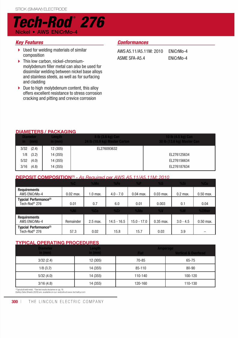
7/18/2019 c110 - Lincoln Electric Consumables 2014
http://slidepdf.com/reader/full/c110-lincoln-electric-consumables-2014 300/511300 ı T H E L I N C O L N E L E C T R I C C O M P A N Y
STICK (SMAW) ELECTRODE
Tech-Rod ®
276 Nickel • AWS ENiCrMo-4
AWS A5.11/A5.11M: 2010 ENiCrMo-4
ASME SFA-A5.4 ENiCrMo-4
Conformances
DIAMETERS / PACKAGINGDiameter Length
in (mm)8 lb (3.6 kg) Can
24 lb (10.9 kg) Master Carton10 lb (4.5 kg) Can
30 lb (13.6 kg) Master Canin (mm)
3/32
1/8
5/32
3/16
(2.4)
(3.2)
(4.0)
(4.8)
12 (305)
14 (355)
14 (355)
14 (355)
EL276093632
EL276125634
EL276156634
EL276187634
TYPICAL OPERATING PROCEDURESDiameterin (mm)
Lengthin (mm)
AmperageFlat Vertical & Overhead
3/32 (2.4) 12 (305) 70-85 65-75
1/8 (3.2) 14 (355) 85-110 80-90
5/32 (4.0) 14 (355) 110-140 100-120
3/16 (4.8) 14 (355) 120-160 110-130
DEPOSIT COMPOSITION(1) - As Required per AWS A5.11/A5.11M: 2010
%C %Mn %Fe %P %S %Si %Cu
Requirements AWS ENiCrMo-4 0.02 max. 1.0 max. 4.0 - 7.0 0.04 max. 0.03 max. 0.2 max. 0.50 max.
Typcial Performance(2)
Tech-Rod® 276 0.01 0.7 6.0 0.01 0.003 0.1 0.04
%Ni %Co %Cr %Mo %V %W %Other
Requirements AWS ENiCrMo-4 Remainder 2.5 max. 14.5 - 16.5 15.0 - 17.0 0.35 max. 3.0 - 4.5 0.50 max.
Typcial Performance(2)
Tech-Rod® 276 57.3 0.02 15.8 15.7 0.03 3.9 –
(1)Typical all weld metal. (2)See test results disclaimer on pg. 18.Safety Data Sheets (SDS) are available on our website at www.techalloy.com
Used for welding materials of similarcomposition
This low carbon, nickel-chromium-molybdenum filler metal can also be used fordissimilar welding between nickel base alloysand stainless steels, as well as for surfacingand cladding
Due to high molybdenum content, this alloyoffers excellent resistance to stress corrosioncracking and pitting and crevice corrosion
Key Features
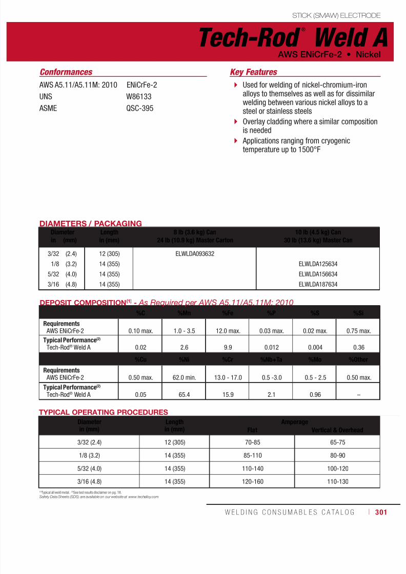
7/18/2019 c110 - Lincoln Electric Consumables 2014
http://slidepdf.com/reader/full/c110-lincoln-electric-consumables-2014 301/511W E L D I N G C O N S U M A B L E S C A TA L O G ı 301
STICK (SMAW) ELECTRODE
Tech-Rod ®
Weld A AWS ENiCrFe-2 • Nickel
AWS A5.11/A5.11M: 2010 ENiCrFe-2
UNS W86133 ASME QSC-395
Conformances
DIAMETERS / PACKAGINGDiameter Length
in (mm)8 lb (3.6 kg) Can
24 lb (10.9 kg) Master Carton10 lb (4.5 kg) Can
30 lb (13.6 kg) Master Canin (mm)
3/32
1/8
5/32
3/16
(2.4)
(3.2)
(4.0)
(4.8)
12 (305)
14 (355)
14 (355)
14 (355)
ELWLDA093632
ELWLDA125634
ELWLDA156634
ELWLDA187634
TYPICAL OPERATING PROCEDURES
Diameterin (mm)
Lengthin (mm)
AmperageFlat Vertical & Overhead
3/32 (2.4) 12 (305) 70-85 65-75
1/8 (3.2) 14 (355) 85-110 80-90
5/32 (4.0) 14 (355) 110-140 100-120
3/16 (4.8) 14 (355) 120-160 110-130
DEPOSIT COMPOSITION(1) - As Required per AWS A5.11/A5.11M: 2010
%C %Mn %Fe %P %S %Si
Requirements AWS ENiCrFe-2 0.10 max. 1.0 - 3.5 12.0 max. 0.03 max. 0.02 max. 0.75 max.
Typical Performance(2)
Tech-Rod® Weld A 0.02 2.6 9.9 0.012 0.004 0.36
%Cu %Ni %Cr %Nb+Ta %Mo %Other
Requirements AWS ENiCrFe-2 0.50 max. 62.0 min. 13.0 - 17.0 0.5 -3.0 0.5 - 2.5 0.50 max.
Typical Performance(2)
Tech-Rod® Weld A 0.05 65.4 15.9 2.1 0.96 –
(1)Typical all weld metal. (2)See test results disclaimer on pg. 18.
Safety Data Sheets (SDS) are available on our website at www.techalloy.com
Used for welding of nickel-chromium-ironalloys to themselves as well as for dissimilarwelding between various nickel alloys to asteel or stainless steels
Overlay cladding where a similar compositionis needed
Applications ranging from cryogenictemperature up to 1500°F
Key Features
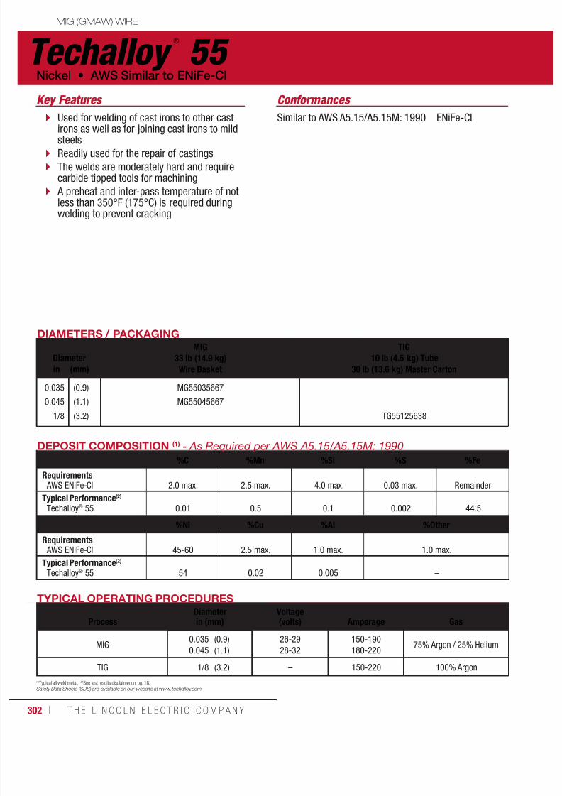
7/18/2019 c110 - Lincoln Electric Consumables 2014
http://slidepdf.com/reader/full/c110-lincoln-electric-consumables-2014 302/511302 ı T H E L I N C O L N E L E C T R I C C O M P A N Y
Techalloy ®
55 Nickel • AWS Similar to ENiFe-Cl
MIG (GMAW) WIRE
Similar to AWS A5.15/A5.15M: 1990 ENiFe-CI
Conformances
DIAMETERS / PACKAGING
DiameterMIG
33 lb (14.9 kg)Wire Basket
TIG10 lb (4.5 kg) Tube
30 lb (13.6 kg) Master Cartonin (mm)
0.035
0.045
1/8
(0.9)
(1.1)
(3.2)
MG55035667
MG55045667
TG55125638
TYPICAL OPERATING PROCEDURES
ProcessDiameterin (mm)
Voltage(volts)
Amperage
Gas
MIG0.035
0.045
(0.9)
(1.1)
26-29
28-32
150-190
180-22075% Argon / 25% Helium
TIG 1/8 (3.2) – 150-220 100% Argon
DEPOSIT COMPOSITION (1) - As Required per AWS A5.15/A5.15M: 1990
%C %Mn %Si %S %Fe
Requirements AWS ENiFe-Cl 2.0 max. 2.5 max. 4.0 max. 0.03 max. Remainder
Typical Performance(2)
Techalloy® 55 0.01 0.5 0.1 0.002 44.5
%Ni %Cu %Al %Other
Requirements AWS ENiFe-Cl 45-60 2.5 max. 1.0 max. 1.0 max.
Typical Performance(2)
Techalloy® 55 54 0.02 0.005 –
(1)Typical all weld metal. (2)See test results disclaimer on pg. 18.
Safety Data Sheets (SDS) are available on our website at www.techalloy.com
Used for welding of cast irons to other castirons as well as for joining cast irons to mildsteels
Readily used for the repair of castings
The welds are moderately hard and requirecarbide tipped tools for machining
A preheat and inter-pass temperature of notless than 350°F (175°C) is required duringwelding to prevent cracking
Key Features
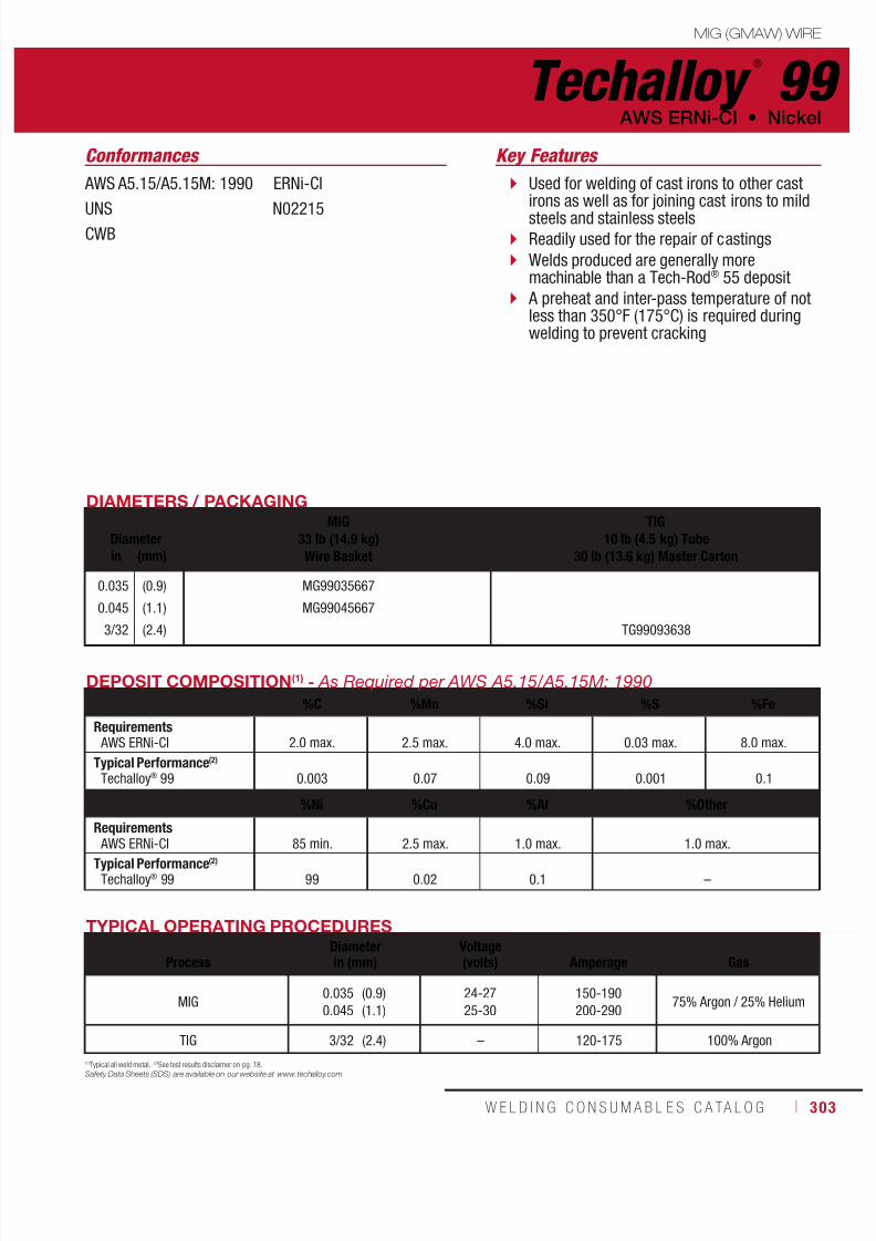
7/18/2019 c110 - Lincoln Electric Consumables 2014
http://slidepdf.com/reader/full/c110-lincoln-electric-consumables-2014 303/511W E L D I N G C O N S U M A B L E S C A TA L O G ı 303
MIG (GMAW) WIRE
Techalloy ®
99 AWS ERNi-CI • Nickel
AWS A5.15/A5.15M: 1990 ERNi-CI
UNS N02215CWB
Conformances
DIAMETERS / PACKAGING
DiameterMIG
33 lb (14.9 kg)Wire Basket
TIG10 lb (4.5 kg) Tube
30 lb (13.6 kg) Master Cartonin (mm)
0.035
0.045
3/32
(0.9)
(1.1)
(2.4)
MG99035667
MG99045667
TG99093638
TYPICAL OPERATING PROCEDURES
ProcessDiameterin (mm)
Voltage(volts)
Amperage
Gas
MIG0.035
0.045
(0.9)
(1.1)
24-27
25-30
150-190
200-29075% Argon / 25% Helium
TIG 3/32 (2.4) – 120-175 100% Argon
DEPOSIT COMPOSITION(1) - As Required per AWS A5.15/A5.15M: 1990
%C %Mn %Si %S %Fe
Requirements AWS ERNi-CI 2.0 max. 2.5 max. 4.0 max. 0.03 max. 8.0 max.
Typical Performance(2)
Techalloy® 99 0.003 0.07 0.09 0.001 0.1
%Ni %Cu %Al %Other
Requirements
AWS ERNi-CI 85 min. 2.5 max. 1.0 max. 1.0 max.Typical Performance(2)
Techalloy® 99 99 0.02 0.1 –
(1)Typical all weld metal. (2)See test results disclaimer on pg. 18.
Safety Data Sheets (SDS) are available on our website at www.techalloy.com
Used for welding of cast irons to other castirons as well as for joining cast irons to mildsteels and stainless steels
Readily used for the repair of castings
Welds produced are generally moremachinable than a Tech-Rod® 55 deposit
A preheat and inter-pass temperature of notless than 350°F (175°C) is required duringwelding to prevent cracking
Key Features

7/18/2019 c110 - Lincoln Electric Consumables 2014
http://slidepdf.com/reader/full/c110-lincoln-electric-consumables-2014 304/511304 ı T H E L I N C O L N E L E C T R I C C O M P A N Y
Techalloy ®
208 Nickel • AWS ERNi-1
MIG (GMAW) WIRE
AWS A5.14 ERNi-1
UNS N02061CWB
Conformances
DIAMETERS / PACKAGING
DiameterMIG
33 lb (14.9 kg)Wire Basket
TIG10 lb (4.5 kg) Tube
30 lb (13.6 kg) Master Cartonin (mm)
0.035
0.045
1/16
3/32
1/8
(0.9)
(1.1)
(1.6)
(2.4)
(3.2)
MG208035667
MG208045667
MG208062667 TG208062638
TG208093638
TG208125638
TYPICAL OPERATING PROCEDURES
ProcessDiameterin (mm)
Voltage(volts)
Amperage
Gas
MIG
0.035
0.045
1/16
(0.9)
(1.1)
(1.6)
24-29
26-30
29-33
180-200
250-270
200-250
75% Argon / 25% Helium
TIG
1/16
3/32
1/8
(1.6)
(2.4)
(3.2)
–
–
–
90-130
120-175
150-220
100% Argon
DEPOSIT COMPOSITION
%C %Mn %Fe %P %S %Si
Requirements AWS ERNi-1 0.15 max. 1.0 max. 1.0 max. 0.03 max. 0.015 max. 0.75 max.
Typical Performance(2)
Techalloy® 208 0.005 0.4 0.04 0.004 0.002 0.44
%Cu %Ni %Al %Ti %Other
Requirements AWS ERNi-1 0.25 max. 93.0 min 1.5 max. 2.0 - 3.5 0.50 max
Typical Performance(2)
Techalloy
®
208 0.02 96.0 0.1 2.8 –
(1)Typical all weld metal. (2)See test results disclaimer on pg. 18.
Safety Data Sheets (SDS) are available on our website at www.techalloy.com
For TIG, MIG and SAW welding of nickel 200or 201
This filler metal is also employed for overlayon steel as well as repairing cast iron castings
Used for dissimilar joints between nickel ornickel alloys to stainless or ferritic steels
Key Features
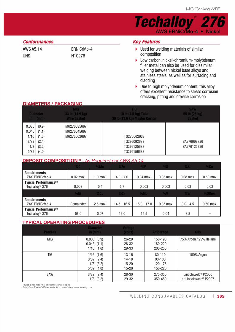
7/18/2019 c110 - Lincoln Electric Consumables 2014
http://slidepdf.com/reader/full/c110-lincoln-electric-consumables-2014 305/511W E L D I N G C O N S U M A B L E S C A TA L O G ı 305
MIG (GMAW) WIRE
Techalloy ®
276 AWS ERNiCrMo-4 • Nickel
AWS A5.14
UNS
ERNiCrMo-4
N10276
Conformances
DIAMETERS / PACKAGING
Diameter
MIG
33 lb (14.9 kg)Wire Basket
TIG
10 lb (4.5 kg) Tube30 lb (13.6 kg) Master Carton
SAW
55 lb (25 kg)Basketin (mm)
0.035
0.045
1/16
3/32
1/8
5/32
(0.9)
(1.1)
(1.6)
(2.4)
(3.2)
(4.0)
MG276035667
MG276045667
MG276062667 TG276062638
TG276093638
TG276125638
TG276156638
SA276093726
SA276125726
TYPICAL OPERATING PROCEDURES
ProcessDiameterin (mm)
Voltage(volts)
Amperage
Gas
MIG 0.035
0.045
1/16
(0.9)
(1.1)
(1.6)
26-29
28-32
29-33
150-190
180-220
200-250
75% Argon / 25% Helium
TIG 1/16
3/32
1/8
5/32
(1.6)
(2.4)
(3.2)
(4.0)
13-16
14-18
15-20
15-20
80-110
90-130
120-175
150-220
100% Argon
SAW 3/32
1/8
(2.4)
(3.2)
28-30
29-32
275-350
350-450
Lincolnweld® P2000
or Lincolnweld® P2007
DEPOSIT COMPOSITION(1) - As Required per AWS A5.14
%C %Mn %Fe %P %S %Si %Cu
Requirements AWS ERNiCrMo-4 0.02 max. 1.0 max. 4.0 - 7.0 0.04 max. 0.03 max. 0.08 max. 0.50 max
Typcial Performance(2)
Techalloy® 276 0.008 0.4 5.7 0.003 0.002 0.03 0.02
%Ni %Co %Cr %Mo %V %W %Other
Requirements AWS ERNiCrMo-4 Remainder 2.5 max. 14.5 - 16.5 15.0 - 17.0 0.35 max. 3.0 - 4.5 0.50 max.
Typcial Performance(2)
Techalloy® 276 58.0 0.07 16.0 15.5 0.04 3.8 –
(1)Typical all weld metal. (2)See test results disclaimer on pg. 18.
Safety Data Sheets (SDS) are available on our website at www.techalloy.com
Used for welding materials of similarcomposition
Low carbon, nickel-chromium-molybdenumfiller metal can also be used for dissimilarwelding between nickel base alloys andstainless steels, as well as for surfacing andcladding
Due to high molybdenum content, this alloyoffers excellent resistance to stress corrosioncracking, pitting and crevice corrosion
Key Features
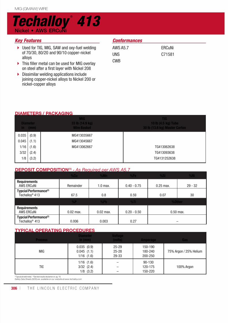
7/18/2019 c110 - Lincoln Electric Consumables 2014
http://slidepdf.com/reader/full/c110-lincoln-electric-consumables-2014 306/511306 ı T H E L I N C O L N E L E C T R I C C O M P A N Y
Techalloy ®
413 Nickel • AWS ERCuNi
MIG (GMAW) WIRE
AWS A5.7 ERCuNi
UNS C71581CWB
Conformances
DIAMETERS / PACKAGING
DiameterMIG
33 lb (14.9 kg)Wire Basket
TIG10 lb (4.5 kg) Tube
30 lb (13.6 kg) Master Cartonin (mm)
0.035
0.045
1/16
3/32
1/8
(0.9)
(1.1)
(1.6)
(2.4)
(3.2)
MG413035667
MG413045667
MG413062667 TG413062638
TG413093638
TG4131252638
TYPICAL OPERATING PROCEDURES
ProcessDiameterin (mm)
Voltage(volts)
Amperage
Gas
MIG
0.035
0.045
1/16
(0.9)
(1.1)
(1.6)
25-29
25-28
29-33
150-190
180-240
200-250
75% Argon / 25% Helium
TIG
1/16
3/32
1/8
(1.6)
(2.4)
(3.2)
–
–
–
90-130
120-175
150-220
100% Argon
DEPOSIT COMPOSITION(1) - As Required per AWS A5.7
%Cu %Mn %Fe %Si %Ni
Requirements AWS ERCuNi Remainder 1.0 max. 0.40 - 0.75 0.25 max. 29 - 32
Typcial Performance(2)
Techalloy® 413 67.5 0.8 0.59 0.07 30
%P %Pb %Ti %Other
Requirements AWS ERCuNi 0.02 max. 0.02 max. 0.20 - 0.50 0.50 max.
Typcial Performance(2)
Techalloy® 413 0.006 0.003 0.27 –
(1)Typical all weld metal. (2)See test results disclaimer on pg. 18.Safety Data Sheets (SDS) are available on our website at www.techalloy.com
Used for TIG, MIG, SAW and oxy-fuel weldingof 70/30, 80/20 and 90/10 copper-nickelalloys
This filler metal can be used for MIG overlayon steel after a first layer with Nickel 208
Dissimilar welding applications include joining copper-nickel alloys to Nickel 200 ornickel-copper alloys
Key Features
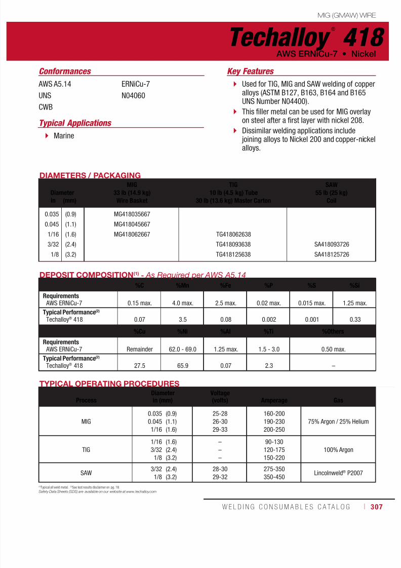
7/18/2019 c110 - Lincoln Electric Consumables 2014
http://slidepdf.com/reader/full/c110-lincoln-electric-consumables-2014 307/511

7/18/2019 c110 - Lincoln Electric Consumables 2014
http://slidepdf.com/reader/full/c110-lincoln-electric-consumables-2014 308/511308 ı T H E L I N C O L N E L E C T R I C C O M P A N Y
Techalloy ®
606 Nickel • AWS ERNiCr-3
MIG (GMAW) WIRE
AWS A5.14 ERNiCr-3
UNS N06082
Conformances
DIAMETERS / PACKAGING
DiameterMIG
33 lb (14.9 kg)Wire Basket
TIG10 lb (4.5 kg) Tube
30 lb (13.6 kg) Master Carton
SAW60 lb (27.2 kg)
Coilin (mm)
0.035
0.045
1/16
3/32
1/8
(0.9)
(1.1)
(1.6)
(2.4)
(3.2)
MG606035667
MG606045667
MG606062667 TG606062638
TG606093638
TG606125638
SA606093726
SA606125726
TYPICAL OPERATING PROCEDURES
ProcessDiameterin (mm)
Voltage(volts)
Amperage
Gas
MIG 0.0350.0451/16
(0.9)(1.1)(1.6)
26-2928-3229-33
150-190180-220200-250
75% Argon / 25% Helium
TIG 1/163/321/8
(1.6)(2.4)(3.2)
–––
90-130120-175150-220
100% Argon
SAW 3/321/8
(2.4)(3.2)
28-3029-32
275-350350-450
Suitable Fluxmay be used
DEPOSIT COMPOSITION(1) - As Required per AWS A5.14
%C %Mn %Fe %P %S %Si
Requirements AWS ERNiCr-3 0.10 max. 2.5 - 3.5 3.0 max. 0.03 max. 0.015 0.50 max.
Typical Performance(2)
Techalloy® 606 0.04 3.1 0.9 0.003 0.002 0.03
%Cu %Ni %Ti %Cr %Nb + Ta %Others
Requirements AWS ERNiCr-3 0.50 max. 67.0 min 0.75 max. 18.0 - 22.0 2.0 - 3.0 0.50 max.
Typical Performance(2)
Techalloy® 606 0.01 71.7 0.42 21.0 2.4 –
(1)Typical all weld metal. (2)See test results disclaimer on pg. 18.
Safety Data Sheets (SDS) are available on our website at www.techalloy.com
Used for TIG, MIG and SAW welding of basematerials such as ASTM B163, B166, B167and B168 alloys which have UNS NumberN06600
Suitable for applications ranging fromcryogenic to high temperatures making thisalloy on of the most used in the nickel family
This filler metal can also be used for dissimilarwelding applications between various nickelalloys and stainless or carbon steels, as wellas for overlay
Key Features
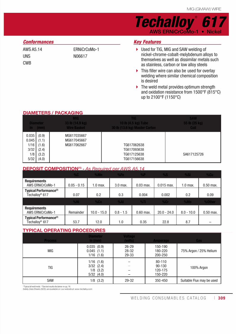
7/18/2019 c110 - Lincoln Electric Consumables 2014
http://slidepdf.com/reader/full/c110-lincoln-electric-consumables-2014 309/511W E L D I N G C O N S U M A B L E S C A TA L O G ı 309
MIG (GMAW) WIRE
Techalloy ®
617 AWS ERNiCrCoMo-1 • Nickel
AWS A5.14 ERNiCrCoMo-1
UNS N06617CWB
Conformances
DIAMETERS / PACKAGING
DiameterMIG
33 lb (14.9 kg)Wire Basket
TIG10 lb (4.5 kg) Tube
30 lb (13.6 kg) Master Carton
SAW55 lb (25 kg)
Coilin (mm)
0.035
0.045
1/16
3/32
1/8
5/32
(0.9)
(1.1)
(1.6)
(2.4)
(3.2)
(4.0)
MG617035667
MG617045667
MG617062667 TG617062638
TG617093638
TG617125638
TG617156638
SA617125726
TYPICAL OPERATING PROCEDURES
ProcessDiameterin (mm)
Voltage(volts)
Amperage
Gas
MIG0.0350.0451/16
(0.9)(1.1)(1.6)
26-2928-3229-33
150-190180-220200-250
75% Argon / 25% Helium
TIG
1/163/321/8
5/32
(1.6)(2.4)(3.2)(4.0)
––––
80-11090-130120-175150-220
100% Argon
SAW 1/8 (3.2) 29-32 350-450 Suitable Flux may be used
DEPOSIT COMPOSITION(1) - As Required per AWS A5.14
%C %Mn %Fe %P %S %Si %Cu
Requirements AWS ERNiCrCoMo-1 0.05 - 0.15 1.0 max. 3.0 max. 0.03 max. 0.015 max. 1.0 max. 0.50 max.
Typical Performance(2)
Techalloy® 617 0.07 0.2 0.3 0.004 0.002 0.2 0.09
%Ni %Co %Al %Ti %Cr %Mo %Other
Requirements AWS ERNiCrCoMo-1 Remainder 10.0 - 15.0 0.8 - 1.5 0.60 max. 20.0 - 24.0 8.0 - 10.0 0.50 max.
Typical Performance(2)
Techalloy® 617 53.7 12.0 1.0 0.35 22.8 8.7 –
(1)Typical all weld metal. (2)See test results disclaimer on pg. 18.
Safety Data Sheets (SDS) are available on our website at www.techalloy.com
Used for TIG, MIG and SAW welding ofnickel-chrome-cobalt-molybdenum alloys tothemselves as well as dissimilar metals suchas stainless, carbon or low alloy steels
This filler wire can also be used for overlaywelding where similar chemical compositionis desired
The weld metal provides optimum strengthand oxidation resistance from 1500°F (815°C)up to 2100°F (1150°C)
Key Features

7/18/2019 c110 - Lincoln Electric Consumables 2014
http://slidepdf.com/reader/full/c110-lincoln-electric-consumables-2014 310/511310 ı T H E L I N C O L N E L E C T R I C C O M P A N Y
AWS A5.14 ERNiCrMo-10
UNS N06022
CWB
Conformances
Techalloy ®
622 Nickel • AWS ERNiCrMo-10
MIG (GMAW) WIRE
DIAMETERS / PACKAGING
DiameterMIG
33 lb (14.9 kg)Wire Basket
TIG10 lb (4.5 kg) Tube
30 lb (13.6 kg) Master Carton
SAW60 lb (27.2 kg)
Coilin (mm)
0.035
0.045
1/16
3/32
1/8
(0.9)
(1.1)
(1.6)
(2.4)
(3.2)
MG622035667
MG622045667
MG622062667 TG622062638
TG622093638
TG622125638
SA622093726
TYPICAL OPERATING PROCEDURES
ProcessDiameterin (mm)
Voltage(volts)
Amperage
Gas
MIG0.0350.0451/16
(0.9)(1.1)(1.6)
26-2928-3229-33
140-190160-200200-250
75% Argon / 25% Helium
TIG1/163/32
1/8
(1.6)(2.4)(3.2)
–––
90-130120-175150-220
100% Argon
SAW 3/32 (2.4) 28-30 275-350 Suitable Flux may be used
DEPOSIT COMPOSITION(1) - As Required per AWS A5.14%C %Mn %Fe %P %S %Si %Cu
Requirements AWS ERNiCrMo-10 0.015 max. 0.50 max. 2.0 - 6.0 0.02 max. 0.010 max. 0.08 max. 0.50 max.
Typical Performance(2)
Techalloy® 622 0.01 0.01 4.5 0.003 0.002 0.07 0.01
%Ni %Co %Cr %Mo %V %W %Other
Requirements AWS ERNiCrMo-10 Remainder 2.50 max. 20.0 - 22.5 12.5 - 14.5 0.35 max. 2.5 - 3.5 0.50 max.
Typical Performance(2)
Techalloy®
622 55.89 0.02 21.8 13.8 0.01 3.1 –
(1)Typical all weld metal. (2)See test results disclaimer on pg. 18.
Safety Data Sheets (SDS) are available on our website at www.techalloy.com
A nickel based alloy with chromium, molybdenum,and tungsten as the principal alloying elements
Used to weld alloys of similar composition as wellas dissimilar joints between nickel-chromium-molybdenum alloys and stainless, carbon or lowalloy steels
Used for cladding overlay as well as thermal sprayapplications
Excellent corrosion resistance in oxidizing as wellas reducing media in a wide variety of chemicalprocess environments
Outstanding resistance to stress corrosion cracking,pitting and crevice corrosion
Key Features

7/18/2019 c110 - Lincoln Electric Consumables 2014
http://slidepdf.com/reader/full/c110-lincoln-electric-consumables-2014 311/511W E L D I N G C O N S U M A B L E S C A TA L O G ı 311
MIG (GMAW) WIRE
Techalloy ®
625 AWS ERNiCrMo-3 • Nickel
AWS A5.14 ERNiCrMo-3
UNS N06625
DIAMETERS / PACKAGING
DiameterMIG
33 lb (14.9 kg)Wire Basket
TIG10 lb (4.5 kg) Tube
30 lb (13.6 kg) Master Carton
SAW55 lb (25 kg)
Basketin (mm)
0.0350.0451/163/321/8
5/32
(0.9)(1.1)(1.6)(2.4)(3.2)(4.0)
MG625035667MG625045667MG625062667 TG625062638
TG625093638TG625125638TG625156638
SA625093726SA625125726
TYPICAL OPERATING PROCEDURESProcess Diameter in (mm) Voltage (volts) Amperage Gas
MIG0.0350.0451/16
(0.9)(1.1)(1.6)
26-2928-3229-33
150-190180-220200-250
75% Argon / 25% Helium
TIG
1/163/321/8
5/32
(1.6)(2.4)(3.2)(4.0)
––––
80-11090-130120-175150-220
100% Argon
SAW 3/321/8
(2.4)(3.2)
28-3029-32
275-350350-450
Lincolnweld® P2000 andLincolnweld® P2007
DEPOSIT COMPOSITION(1) - As Required per AWS A5.14%C %Mn %Fe %P %S
Requirements AWS ERNiCrMo-3 0.10 max. 0.50 max. 5.0 max. 0.02 max. 0.015 max.
Typcial Performance(2)
Techalloy® 625 0.02 0.20 0.28 0.005 0.002
%Si %Cu %Ni %Al %TiRequirements AWS ERNiCrMo-3 0.50 max. 0.50 max. 58.0 min. 0.40 max. 0.40 max.
Typcial Performance(2)
Techalloy® 625 0.06 0.01 63.9 0.11 0.21
%Cr %Nb+Ta %Mo %Other
Requirements AWS ERNiCrMo-3 20.0 - 23.0 3.15 - 4.15 8.0 - 10.0 0.50 max.
Typcial Performance(2)
Techalloy® 625 22.7 3.66 8.5 –
Conformances
(1)Typical all weld metal. (2)See test results disclaimer on pg. 18.
Safety Data Sheets (SDS) are available on our website at www.techalloy.com
Used for TIG, MIG and SAW welding of nickel-chromium-molybdenum alloys
The same chemical and mechanical properties(Weld Metal) but with slightly different wirecharacteristics suited to the hot wire TIG process
This filler metal may be used for cladding andwelding dissimilar base metals such as Ni-Cr-Moalloys to stainless and carbon steels
The Ni-Cr-Mo alloy system provides excellentresistance to oxidizing and reducing environments
The high molybdenum content provides goodstress, pitting and crevice corrosion resistance
Key Features
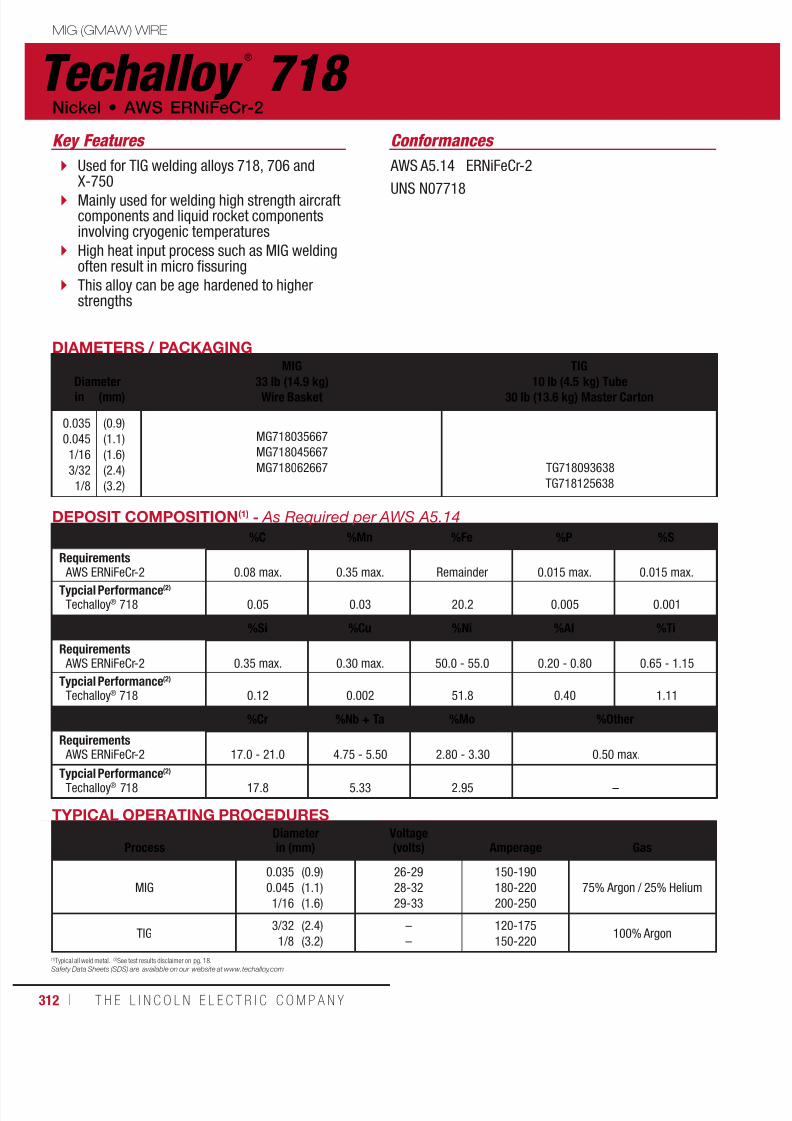
7/18/2019 c110 - Lincoln Electric Consumables 2014
http://slidepdf.com/reader/full/c110-lincoln-electric-consumables-2014 312/511312 ı T H E L I N C O L N E L E C T R I C C O M P A N Y
Techalloy ®
718 Nickel • AWS ERNiFeCr-2
MIG (GMAW) WIRE
AWS A5.14 ERNiFeCr-2
UNS N07718
DIAMETERS / PACKAGING
Diameter
MIG
33 lb (14.9 kg)Wire Basket
TIG
10 lb (4.5 kg) Tube30 lb (13.6 kg) Master Cartonin (mm)
0.035
0.045
1/16
3/32
1/8
(0.9)
(1.1)
(1.6)
(2.4)
(3.2)
MG718035667
MG718045667
MG718062667 TG718093638
TG718125638
TYPICAL OPERATING PROCEDURES
ProcessDiameterin (mm)
Voltage(volts)
Amperage
Gas
MIG
0.035
0.045
1/16
(0.9)
(1.1)
(1.6)
26-29
28-32
29-33
150-190
180-220
200-250
75% Argon / 25% Helium
TIG3/32
1/8
(2.4)
(3.2)
–
–
120-175
150-220100% Argon
DEPOSIT COMPOSITION(1) - As Required per AWS A5.14
%C %Mn %Fe %P %S
Requirements
AWS ERNiFeCr-2 0.08 max. 0.35 max. Remainder 0.015 max. 0.015 max.Typcial Performance(2)
Techalloy® 718 0.05 0.03 20.2 0.005 0.001
%Si %Cu %Ni %Al %Ti
Requirements AWS ERNiFeCr-2 0.35 max. 0.30 max. 50.0 - 55.0 0.20 - 0.80 0.65 - 1.15
Typcial Performance(2)
Techalloy® 718 0.12 0.002 51.8 0.40 1.11
%Cr %Nb + Ta %Mo %Other
Requirements AWS ERNiFeCr-2 17.0 - 21.0 4.75 - 5.50 2.80 - 3.30 0.50 max.
Typcial Performance(2)
Techalloy® 718 17.8 5.33 2.95 –
Conformances
(1)Typical all weld metal. (2)See test results disclaimer on pg. 18.Safety Data Sheets (SDS) are available on our website at www.techalloy.com
Used for TIG welding alloys 718, 706 andX-750
Mainly used for welding high strength aircraftcomponents and liquid rocket componentsinvolving cryogenic temperatures
High heat input process such as MIG weldingoften result in micro fissuring
This alloy can be age hardened to higherstrengths
Key Features

7/18/2019 c110 - Lincoln Electric Consumables 2014
http://slidepdf.com/reader/full/c110-lincoln-electric-consumables-2014 313/511W E L D I N G C O N S U M A B L E S C A TA L O G ı 313
MIG (GMAW) WIRE
Techalloy ®
825 AWS ERNiFeCr-1 • Nickel
AWS A5.14 ERNiFeCr-1
UNS N08065
DIAMETERS / PACKAGING
DiameterMIG
33 lb (14.9 kg)Wire Basket
TIG10 lb (4.5 kg) Tube
30 lb (13.6 kg) Master Cartonin (mm)
0.035
0.045
1/16
3/32
1/8
(0.9)
(1.1)
(1.6)
(2.4)
(3.2)
MG825035667
MG825045667
MG825062667 TG825062638
TG825093638
TG825125638
TYPICAL OPERATING PROCEDURES
ProcessDiameterin (mm)
Voltage(volts)
Amperage
Gas
MIG
0.035
0.045
1/16
(0.9)
(1.1)
(1.6)
26-29
28-32
29-33
150-190
180-220
200-250
75% Argon / 25% Helium
TIG
1/16
3/32
1/8
(1.6)
(2.4)
(3.2)
–
–
–
90-130
120-175
150-220
100% Argon
DEPOSIT COMPOSITION(1) - As Required per AWS A5.14
%C %Mn %Fe %P %S %Si %Cu
Requirements AWS ERNiFeCr-1 0.05 max. 1.0 max. 22.0 min 0.03 max. 0.03 max. 0.50 max. 1.5 - 3.0
Typcial Performance(2)
Techalloy® 825 0.007 0.5 28.8 0.01 0.002 0.19 2.1
%Ni %Al %Ti %Cr %Mo %Other
Requirements AWS ERNiFeCr-1 38.0 - 46.0 0.20 max. 0.6 - 1.2 19.5 - 23.5 2.5 - 3.5 0.50 max.
Typcial Performance(2)
Techalloy® 825 41.8 0.13 0.8 22.1 3.0 –
Conformances
(1)Typical all weld metal. (2)See test results disclaimer on pg. 18.Safety Data Sheets (SDS) are available on our website at www.techalloy.com
Used for TIG and MIG welding of nickel-chromium-molybdenum-copper alloys
Can be used to overlay cladding where similarchemical composition is required
Key Features
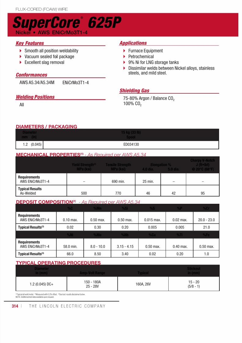
7/18/2019 c110 - Lincoln Electric Consumables 2014
http://slidepdf.com/reader/full/c110-lincoln-electric-consumables-2014 314/511314 ı T H E L I N C O L N E L E C T R I C C O M P A N Y
SuperCore ®
625P FLUX-CORED (FCAW) WIRE
Nickel • AWS ENiCrMo3T1-4
DIAMETERS / PACKAGINGDiameter 15 kg (33 lb)
Spoolmm (in)
1.2 (0.045) ED034130
ApplicationsKey Features
Shielding Gas
Welding Positions
Conformances
Smooth all position weldability
Vacuum sealed foil package Excellent slag removal
Furnace Equipment
Petrochemical 9% Ni for LNG storage tanks
Dissimilar welds between Nickel alloys, stainlesssteels, and mild steel.
75-80% Argon / Balance CO2
100% CO2 All
AWS A5.34/A5.34M ENiCrMo3T1-4
TYPICAL OPERATING PROCEDURESDiameterin (mm)
Amp-Volt Range
Typical
Stickoutin (mm)
1.2 (0.045) DC+150 - 180A
25 - 28V160A, 26V
15 - 20(5/8 - 1)
DEPOSIT COMPOSITION(1) - As Required per AWS A5.34
%C %Mn %Si %S %P %Cr
Requirements AWS ENiCrMo3T1-4 0.10 max. 0.50 max. 0.50 max. 0.015 max. 0.02 max. 20.0 - 23.0
Typical Results(3) 0.02 0.30 0.20 0.005 0.005 21.0
%Ni %Mo %Nb %Cu %Ti %Fe
Requirements AWS ENiCrMo3T1-4 58.0 min. 8.0 - 10.0 3.15 - 4.15 0.50 max. 0.40 max. 0.50 max.
Typical Results(3) 66.0 8.50 3.40 0.02 0.20 1.0
MECHANICAL PROPERTIES(1) - As Required per AWS A5.34
Yield Strength(2)
MPa (ksi)
Tensile Strength
MPa (ksi)
Elongation %
Charpy V-NotchJ (ft•lbf)
4.0 dia. 5.0 dia. @ 20°C (68°F)
Requirements AWS ENiCrMo3T1-4 – 690 min. 25 min. – –
Typical Results As-Welded 500 770 46 42 95
(1)Typical all weld metal. (2)Measured with 0.2% offset. (3)See test results disclaimer below.
NOTE: Additional test data available upon request.

7/18/2019 c110 - Lincoln Electric Consumables 2014
http://slidepdf.com/reader/full/c110-lincoln-electric-consumables-2014 315/511W E L D I N G C O N S U M A B L E S C A TA L O G ı 315
Stick ElectrodeBuild-UpWearshield® BU ..................................... 316
Metal-to-Metal WearWearshield® MI ..................................... 317Wearshield® Mangjet® ........................... 318
Severe ImpactWearshield® 15CrMn ............................. 319Wearshield® FROG MANG® .................... 320
Abrasion Plus ImpactWearshield® ABR ................................... 321Wearshield® 44 ..................................... 322
Metal-to-Earth WearWearshield® ME .................................... 323
Severe AbrasionWearshield® 60 ..................................... 324
Maintenance and RepairBlue Max® 2100 .................................... 325Weartech™ WT-1 SMAW ........................ 326Weartech™ WT-6 SMAW ........................ 327Weartech™ WT-12 SMAW ...................... 328Weartech™ WT-21 SMAW ...................... 329
TIG (GTAW) Cut Lengths Weartech™ WT-1 TIG ............................. 330
Weartech™ WT-6 TIG ............................. 331Weartech™ WT-12 TIG ........................... 332Weartech™ WT-21 TIG ........................... 333
Metal-Cored WireSevere AbrasionLincore® 60-G ....................................... 334Weartech™ WT-1 MIG ............................ 335Weartech™ WT-6 MIG ............................ 336Weartech™ WT-12 MIG .......................... 337Weartech™ WT21 MIG ........................... 338
Metal-Cored Submerged Arc WireBuild-UpLincore® 30-S ....................................... 339
Metal-to-Metal, Build UpLincore® 32-S ....................................... 340Lincore® 35-S ....................................... 341
Metal-to-MetalLincore® 40-S ....................................... 342Lincore® 42-S ....................................... 343
Roll Rebuilding, Build Up
Lincore
®
20 ........................................... 344Lincore® 8620 ....................................... 345Lincore® 4130 ....................................... 346
Roll Rebuilding, Metal-to-MetalLincore® 410 ......................................... 347Lincore® 410NiMo ................................. 348Lincore® 423L ....................................... 349Lincore® 423Cr ..................................... 350
Lincore® 420 ......................................... 351Lincore® 96-S ....................................... 352Lincore® 102W ...................................... 353Lincore® 102HC .................................... 354
Flux-Cored (FCAW-G) WireBuild-UpLincore® BU-G ....................................... 355
Metal-to-MetalLincore® 55-G ....................................... 356
Flux-Cored (FCAW-S) WireBuild-UpLincore® BU........................................... 357Lincore® 33 ........................................... 358
Metal-to-MetalLincore® 40-O ....................................... 359Lincore® 55 ........................................... 360Lincore® T & D ...................................... 361
Severe ImpactLincore® M ............................................ 362
Lincore
®
15CrMn ................................... 363Lincore® FROG MANG® ..........................364
Flux-Cored (FCAW-S) WireAbrasion Plus ImpactLincore® 50 ........................................... 365
Severe AbrasionLincore® 60-O ....................................... 366Lincore® 65-O ....................................... 367
Submerged Arc Flux
HardfacingLincolnweld® A-96-S ............................. 368Lincolnweld® H-535™ ............................ 368Lincolnweld® H-560™ ............................ 369
Neutral FluxLincolnweld® 801® ................................ 369Lincolnweld® 802® ................................ 370Lincolnweld® 803™ ............................... 370
CONSUMABLES
HARDFACING

7/18/2019 c110 - Lincoln Electric Consumables 2014
http://slidepdf.com/reader/full/c110-lincoln-electric-consumables-2014 316/511316 ı T H E L I N C O L N E L E C T R I C C O M P A N Y
Wearshield ®
BU STICK (SMAW) ELECTRODE
Welding Positions
Typical Applications
Flat & Horizontal
For Build-Up Shovel and bucket lips
Pump impellers and housings
Pulverizer plows
Mill hammers
For Hardfacing Trunnions, tractor rolls, cranes and gears
Build-up with moderate hardness to resistshock and metal-to-metal wear, as in rollingand sliding
Can be used as underbase for otherhardfacing deposits or as final overlay onparts to be machined or forged
Unlimited layers with proper preheat,interpass temperatures and procedures
Use on mild and low alloy steels
Build-Up
Key Features
DIAMETERS / PACKAGING
Diameter Length 10 lb (4.5 kg) Carton40 lb (18.1 kg) Master Cartonin (mm) in (mm)
5/32
3/16
(4.0)
(4.8)
14 (350)
14 (350)
ED021991
ED021993
MECHANICAL PROPERTIES(1)
Rockwell Hardness (RC)
1 Layer 2 Layers 3 Layers
15-20 18-23 23-28
TYPICAL OPERATING PROCEDURES
Current (Amps)
Polarity(2) 5/32 in (4.0 mm) 3/16 in (4.8 mm)
DC+ 145-210 180-280
AC 155-225 200-290
NOTE: Using a short arc with a slight weave motion, deposit beads about 1/2 in - 3/4 in (13-19 mm) wide with the 5/32 in and 3/16 in (4.0-4.8 mm) electrodediameters, and about 1 in (25 mm) wide with the 1/4 in (6.4 mm) diameter. However, on edges and corners, fast-moving stringer beads or very narrowweaved beads are usually preferred. The exact width and thickness of the bead will depend on the mass of the piece being welded.
Work-hardened base or weld metal should be removed before applying Wearshield® BU, since such areas are more prone to embrittlement and possiblecracking. The part should be preheated to at least 21°C (70°F). Preheating above 40°C (100°F) is usually not required. Preheating depends largely on the basemetal composition. On large, complex, or restrained parts, a preheat of 150°- 260°C (300°- 500°F) may be necessary.
DEPOSIT COMPOSITION(1)
%C %Mn %Si %Cr %S %P
2 or more layers 0.14 1.15 0.60 1.40 0.025 0.015
(1)Composition and properties depend upon dilution. Single layer deposit properties depend upon base metal and/or build-up material. (2)Preferred polarity is listed first.
IMPORTANT: SPECIAL VENTILATION AND/OR EXHAUST REQUIRED
Fumes from the normal use of some welding products can contain significant quantities of components - such as chromium and manganese - which can lower the 5.0 mg/m 3 maximum exposure guideline for general welding fume.
BEFORE USE, READ AND UNDERSTAND THE MATERIAL SAFETY DATA SHEET (MSDS) FOR THIS PRODUCT AND SPECIFIC INFORMATION PRINTED ON THE PRODUCT CONTAINER.

7/18/2019 c110 - Lincoln Electric Consumables 2014
http://slidepdf.com/reader/full/c110-lincoln-electric-consumables-2014 317/511W E L D I N G C O N S U M A B L E S C A TA L O G ı 317
IMPORTANT: SPECIAL VENTILATION AND/OR EXHAUST REQUIRED
Fumes from the normal use of some welding products can contain significant quantities of components - such as chromium and manganese - which can lower the 5.0 mg/m 3 maximum exposure guideline for general welding fume.
BEFORE USE, READ AND UNDERSTAND THE MATERIAL SAFETY DATA SHEET (MSDS) FOR THIS PRODUCT AND SPECIFIC INFORMATION PRINTED ON THE PRODUCT CONTAINER.
Wearshield ®
MISTICK (SMAW) ELECTRODE
Welding Positions
Typical Applications
All, except vertical down
Boom heels
Conveyor screws Dipper lips
Tractor grousers
Ditcher teeth
Lumber equipment Hammer mills
Provides a martensitic deposit with considerableretained austenite
General purpose electrode, a good compromisefor metal-to-metal wear, moderate impact andmild abrasion
Can be used on carbon and low alloy steel parts
Deposits tend to cross check crack and areusually best limited to two layers
Metal-to-Metal
Key Features
DIAMETERS / PACKAGING
Diameter Length 10 lb (4.5 kg) Carton40 lb (18.1 kg) Master Cartonin (mm) in (mm)
1/8
5/32
3/16
(3.2)
(4.0)
(4.8)
14 (350)
14 (350)
14 (350)
ED022003
ED022005
ED022007
MECHANICAL PROPERTIES(1)
Rockwell Hardness (RC)1 Layer 2 or More Layers
50 54
TYPICAL OPERATING PROCEDURES
Current (Amps)Polarity(2) 1/8 in (3.2 mm) 5/32 in (4.0 mm) 3/16 in (4.8 mm)
DC+ 70-120 110-150 150-200
AC 70-120 110-150 150-200
NOTE: In welding with Wearshield® MI, a short arc or a long arc may be used. The short arc will give greater build-up with each bead. The long arc is ideal fordepositing thin layers, though alloy recovery may be reduced. In depositing Wearshield® MI, preheat and interpass temperatures of 200°C (400°F) minimumare helpful, as well as limiting deposit to two layers, to reduce cracking and avoid chipping and fragmentation. Weld deposit cannot be cut with oxy-fuelprocess. Plasma arc and air-carbon arc processes can cut or gouge the weld deposit successfully. Grinding is usually best if the deposit needs to be shaped.
DEPOSIT COMPOSITION(1)
On Carbon Steel %C %Mn %Si %Cr %Mo
2 or More Layers 0.9 0.4 0.4 9.5 0.6
(1)Composition and properties depend upon dilution. Single layer deposit properties depend upon base metal and/or build-up material. (2)Preferred polarity is listed first.
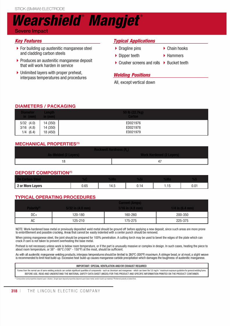
7/18/2019 c110 - Lincoln Electric Consumables 2014
http://slidepdf.com/reader/full/c110-lincoln-electric-consumables-2014 318/511318 ı T H E L I N C O L N E L E C T R I C C O M P A N Y
Wearshield ®
Mangjet ®
STICK (SMAW) ELECTRODE
Welding Positions
Typical Applications
All, except vertical down
Dragline pins
Dipper teeth Crusher screens and rolls
Chain hooks
Hammers Bucket teeth
For building up austenitic manganese steeland cladding carbon steels
Produces an austenitic manganese depositthat will work harden in service
Unlimited layers with proper preheat,interpass temperatures and procedures
Severe Impact
Key Features
DIAMETERS / PACKAGING
Diameter Length 50 lb (22.7kg)Cartonin (mm) in (mm)
5/32
3/16
1/4
(4.0)
(4.8)
(6.4)
14 (350)
14 (350)
18 (450)
ED021976
ED021978
ED021979
MECHANICAL PROPERTIES(1)
Rockwell Hardness (RC)
As-Welded (2 Layers) Work Hardened (2 Layers)
18 47
TYPICAL OPERATING PROCEDURES
Current (Amps)
Polarity(2) 5/32 in (4.0 mm) 3/16 in (4.8 mm) 1/4 in (6.4 mm)
DC+ 120-180 160-260 200-350
AC 125-210 175-275 225-375
NOTE: Work-hardened base metal or previously deposited weld metal should be ground off before applying a new deposit, since such areas are more proneto embrittlement and possible cracking. Areas that cannot be easily indented with a center punch should be removed.
When joining manganese steel, the joint should be prepared for 100% penetration. A cutting torch may be used to bevel the edges of the plate which cancrack if care is not taken to prevent overheating the base metal.
Preheat is not necessary unless work is below room temperature, or if the part is unusually massive or complex in design. In such cases, heating the piece toabout room temperature, or 38° - 66°C (100° - 150°F) at the most, should be sufficient.
As with all austenitic manganese welding products, interpass temperatures should be limited to 260ºC (500ºF) maximum. A stringer bead, or at most, a slight weaveis recommended to limit heat build-up. Excessive heat build-up causes manganese carbide precipitation which damages the toughness of austenitic manganese.
DEPOSIT COMPOSITION(1)
On Carbon Steel %C %Mn %Si %Mo %S
2 or More Layers 0.65 14.5 0.14 1.15 0.01
(1) Composition and properties depend upon dilution. Single layer deposit properties depend upon base metal and/or build-up material. (2)Preferred polarity is listed first.
IMPORTANT: SPECIAL VENTILATION AND/OR EXHAUST REQUIRED
Fumes from the normal use of some welding products can contain significant quantities of components - such as chromium and manganese - which can lower the 5.0 mg/m 3 maximum exposure guideline for general welding fume.
BEFORE USE, READ AND UNDERSTAND THE MATERIAL SAFETY DATA SHEET (MSDS) FOR THIS PRODUCT AND SPECIFIC INFORMATION PRINTED ON THE PRODUCT CONTAINER.
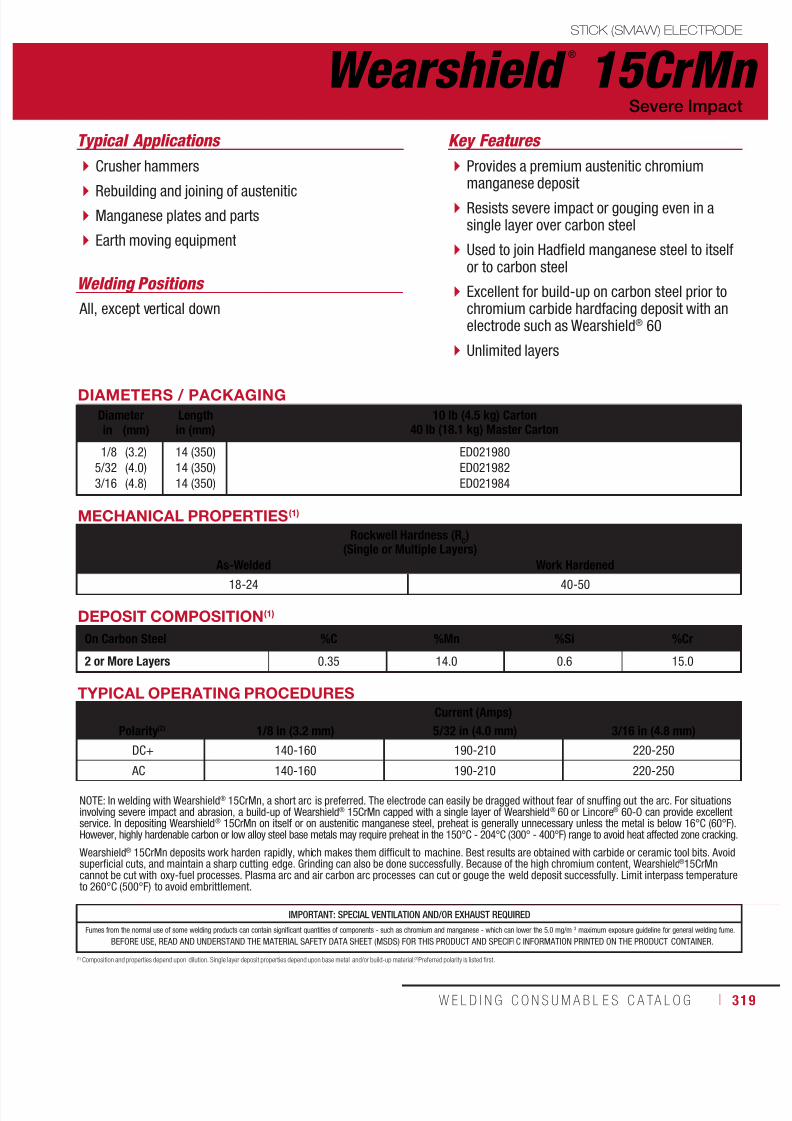
7/18/2019 c110 - Lincoln Electric Consumables 2014
http://slidepdf.com/reader/full/c110-lincoln-electric-consumables-2014 319/511W E L D I N G C O N S U M A B L E S C A TA L O G ı 319
IMPORTANT: SPECIAL VENTILATION AND/OR EXHAUST REQUIRED
Fumes from the normal use of some welding products can contain significant quantities of components - such as chromium and manganese - which can lower the 5.0 mg/m 3 maximum exposure guideline for general welding fume.
BEFORE USE, READ AND UNDERSTAND THE MATERIAL SAFETY DATA SHEET (MSDS) FOR THIS PRODUCT AND SPECIFIC INFORMATION PRINTED ON THE PRODUCT CONTAINER.
Wearshield ®
15CrMnSTICK (SMAW) ELECTRODE
Welding Positions
Typical Applications
All, except vertical down
Crusher hammers
Rebuilding and joining of austenitic Manganese plates and parts
Earth moving equipment
Provides a premium austenitic chromiummanganese deposit
Resists severe impact or gouging even in asingle layer over carbon steel
Used to join Hadfield manganese steel to itselfor to carbon steel
Excellent for build-up on carbon steel prior tochromium carbide hardfacing deposit with anelectrode such as Wearshield® 60
Unlimited layers
Severe Impact
Key Features
DIAMETERS / PACKAGING
Diameter Length 10 lb (4.5 kg) Carton40 lb (18.1 kg) Master Cartonin (mm) in (mm)
1/8
5/32
3/16
(3.2)
(4.0)
(4.8)
14 (350)
14 (350)
14 (350)
ED021980
ED021982
ED021984
MECHANICAL PROPERTIES(1)
Rockwell Hardness (RC)
(Single or Multiple Layers)As-Welded Work Hardened
18-24 40-50
TYPICAL OPERATING PROCEDURES
Current (Amps)
Polarity(2) 1/8 in (3.2 mm) 5/32 in (4.0 mm) 3/16 in (4.8 mm)
DC+ 140-160 190-210 220-250
AC 140-160 190-210 220-250
NOTE: In welding with Wearshield® 15CrMn, a short arc is preferred. The electrode can easily be dragged without fear of snuffing out the arc. For situationsinvolving severe impact and abrasion, a build-up of Wearshield® 15CrMn capped with a single layer of Wearshield® 60 or Lincore® 60-O can provide excellentservice. In depositing Wearshield® 15CrMn on itself or on austenitic manganese steel, preheat is generally unnecessary unless the metal is below 16°C (60°F).However, highly hardenable carbon or low alloy steel base metals may require preheat in the 150°C - 204°C (300° - 400°F) range to avoid heat affected zone cracking.
Wearshield® 15CrMn deposits work harden rapidly, which makes them difficult to machine. Best results are obtained with carbide or ceramic tool bits. Avoidsuperficial cuts, and maintain a sharp cutting edge. Grinding can also be done successfully. Because of the high chromium content, Wearshield®15CrMncannot be cut with oxy-fuel processes. Plasma arc and air carbon arc processes can cut or gouge the weld deposit successfully. Limit interpass temperatureto 260°C (500°F) to avoid embrittlement.
DEPOSIT COMPOSITION(1)
On Carbon Steel %C %Mn %Si %Cr
2 or More Layers 0.35 14.0 0.6 15.0
(1) Composition and properties depend upon dilution. Single layer deposit properties depend upon base metal and/or build-up material. (2)Preferred polarity is listed first.

7/18/2019 c110 - Lincoln Electric Consumables 2014
http://slidepdf.com/reader/full/c110-lincoln-electric-consumables-2014 320/511320 ı T H E L I N C O L N E L E C T R I C C O M P A N Y
Welding Positions
All, except vertical down
Wearshield ®
FROG MANG ®
STICK (SMAW) ELECTRODE
Typical Applications
Manganese crossing diamonds
Manganese railroad frogs
Designed specifically for building up manganese frogsand manganese crossing diamonds in the railroad industry
Provides a high strength, high alloy austenitic manganesedeposit to handle the increased loading of railroad cars
Unlimited layers with proper preheat, interpasstemperatures and procedures
Resistant to deformation and the resultant metal flow
Severe Impact
Key Features
MECHANICAL PROPERTIES(1)
Rockwell Hardness (RC)
As-Welded Work Hardened
20 - 30 40 - 50
DIAMETERS / PACKAGING
Diameter Length 10 lb (4.5 kg) Easy Open Can
30 lb (13.6 kg) Master Carton
12 lb (5.4 kg) Easy Open Can
36 lb (16.3 kg) Master Cartonin (mm) in (mm)5/32
3/16
1/4
(4.0)
(4.8)
(6.4)
14 (350)
14 (350)
18 (450)
ED033134
ED033135
ED033133
DEPOSIT COMPOSITION(1)
On Carbon Steel %C %Mn %Si %Cr
6 Layers 1.20 21.0 0.4 5.3
(1)Composition and properties depend upon dilution. Single layer deposit properties depend upon base metal and/or build-up material. (2)Preferred polarity is listed first.
TYPICAL OPERATING PROCEDURES
Current (Amps)
Polarity(2) 5/32 in (4.0 mm) 3/16 in (4.8 mm) 1/4 in (6.4 mm)
DC+ 140 - 175 175 - 215 235 - 280
AC 150 - 180 185 - 215 235 - 280
NOTE: Weld Preparation Remove all damaged and foreign material by air-carbon arc gouging or grinding. Make sure all defective metal is removed. In theevent hairline cracks remain at flangeway depth, use a 3.2 mm (1/8 in) E308 stainless electrode, such as Blue Max® or Red Baron® 308L AC-DC to tie up
these cracks. This will avoid hot cracking during the build-up process. Apply only thin layers and do not build-up with E308 stainless. This is for emergencysituations where no other alternative is available to repair flangeway cracks.
Use DC+ to avoid excessive spatter. When possible, weld at alternate locations (skip weld) to avoid overheating of metal in a localized area. Do not exceedinterpass temperature of 260°C (500°F). Use a temperature marker 13 mm (1/2 in) from the welded area at frequent intervals to ensure that interpasstemperature does not exceed 260°C (500°F).
Use a short arc and a stringer bead width of 10 to 13 mm (3/8 to 1/2 in).
Finish the casting by grinding to a safe contour. Leave enough weld metal during the welding process to allow a level and even contour after grinding. Makesure all areas are finished and the casting has no further visible defects. Check with straight edge so that the casting is free of low spots. As with all austeniticmanganese welding products, interpass temperatures should be limited to 260°C (500°F) maximum. A stringer bead, or at most, a slight weave is recommendedto limit heat build-up. Excessive heat build-up causes manganese carbide precipitation which damages the toughness of austenitic manganese.
IMPORTANT: SPECIAL VENTILATION AND/OR EXHAUST REQUIRED
Fumes from the normal use of some welding products can contain significant quantities of components - such as chromium and manganese - which can lower the 5.0 mg/m 3 maximum exposure guideline for general welding fume.
BEFORE USE, READ AND UNDERSTAND THE MATERIAL SAFETY DATA SHEET (MSDS) FOR THIS PRODUCT AND SPECIFIC INFORMATION PRINTED ON THE PRODUCT CONTAINER.

7/18/2019 c110 - Lincoln Electric Consumables 2014
http://slidepdf.com/reader/full/c110-lincoln-electric-consumables-2014 321/511W E L D I N G C O N S U M A B L E S C A TA L O G ı 321
IMPORTANT: SPECIAL VENTILATION AND/OR EXHAUST REQUIRED
Fumes from the normal use of some welding products can contain significant quantities of components - such as chromium and manganese - which can lower the 5.0 mg/m 3 maximum exposure guideline for general welding fume.
BEFORE USE, READ AND UNDERSTAND THE MATERIAL SAFETY DATA SHEET (MSDS) FOR THIS PRODUCT AND SPECIFIC INFORMATION PRINTED ON THE PRODUCT CONTAINER.
Wearshield ®
ABRSTICK (SMAW) ELECTRODE
Welding Positions
Typical Applications
All
Crusher hammers
Dozer blades Dipper teeth and lips
Coal mining cutters
Truck chain and gears
Provides good resistance to abrasion, impactand some metal-to-metal wear
Good hot forging properties
Use on carbon, stainless and manganese steels
Deposits limited to two layers
Can be forged readily without affecting itsmechanical properties
Abrasion & Impact
Key Features
DIAMETERS / PACKAGING
Diameter Length 10 lb (4.5 kg) Carton40 lb (18.1 kg) Cartonin (mm) in (mm)
1/8
5/32
3/16
(3.2)
(4.0)
(4.8)
14 (350)
14 (350)
14 (350)
ED021996
ED021998
ED022000
MECHANICAL PROPERTIES(1)
Rockwell Hardness (RC)
1 Layer 2 Layers
24-53 28-53
DEPOSIT COMPOSITION(1)
On Carbon Steel %C %Mn %Si %Cr %Mo
2 Layers 2.1 1.1 0.75 6.5 0.40
(1)Composition and properties depend upon dilution. Single layer deposit properties depend upon base metal and/or build-up material. (2)Preferred polarity is listed first.
TYPICAL OPERATING PROCEDURES
Current (Amps)
Polarity(2) 1/8 in (3.2 mm) 5/32 in (4.0 mm) 3/16 in (4.8 mm)
DC+ 40-150 75-200 110-250
AC 50-165 80-220 120-275
NOTE: Wearshield® ABR can be forged readily without affecting its mechanical properties. As deposited, Wearshield® ABR weld metal is not machinable,although the deposit can be shaped by grinding.
To obtain a deposit that is machinable with carbide tools, heat to about 749ºC (1380ºF) and hold for one hour per inch of thickness.
Air cool to room temperature.
For maximum machinability, heat to 870° - 900°C (1600° - 1650°F) and hold for one hour per inch of thickness. Furnace cool to 650°C (1200°F) at a rate notexceeding 10°C (50°F) per hour, and air or furnace cool to room temperature. Variation in welding procedures will have little affect on abrasion resistance.
The abrasion resistance can be restored by heating to about 790°C (1450°F), quenching and tempering at 200°C (400°F).
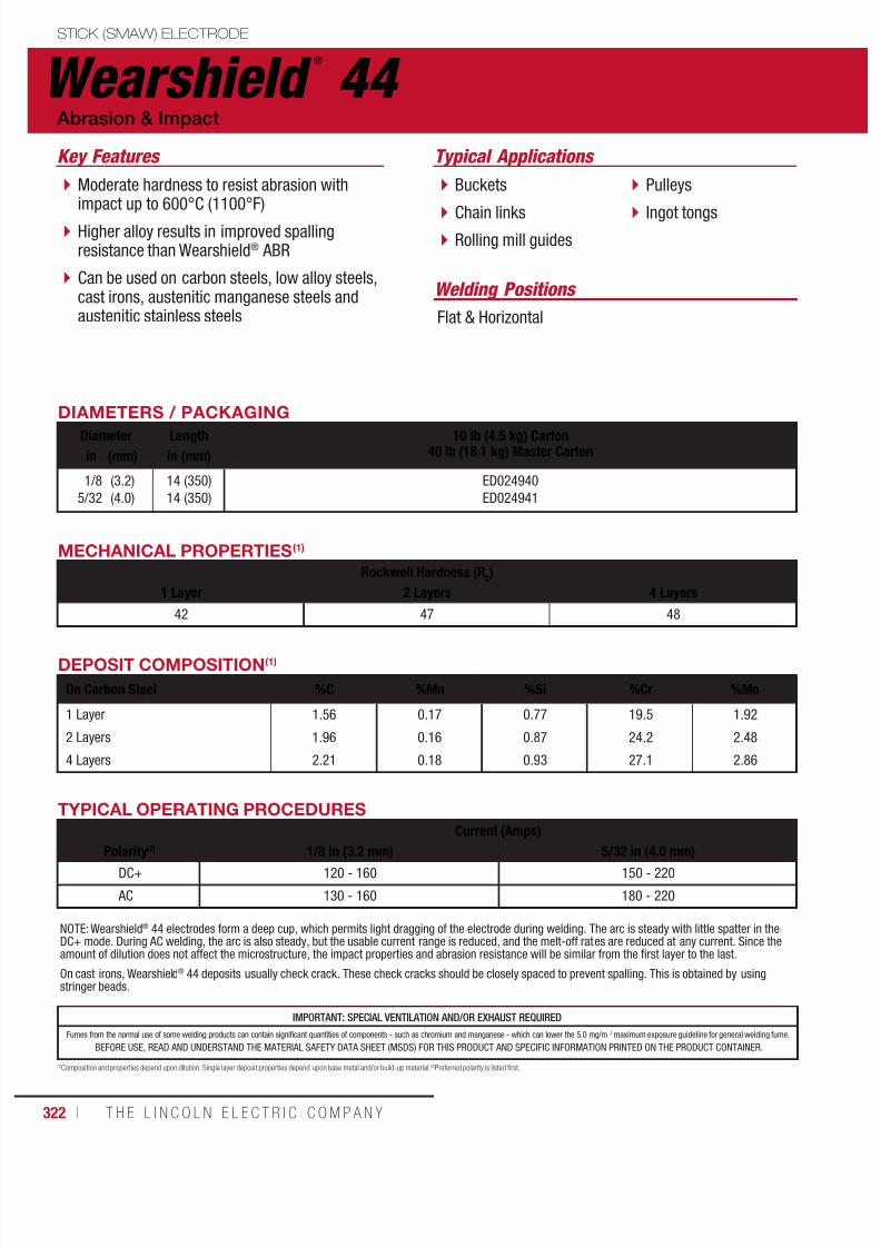
7/18/2019 c110 - Lincoln Electric Consumables 2014
http://slidepdf.com/reader/full/c110-lincoln-electric-consumables-2014 322/511322 ı T H E L I N C O L N E L E C T R I C C O M P A N Y
Wearshield ®
44 STICK (SMAW) ELECTRODE
Welding Positions
Typical Applications
Flat & Horizontal
Buckets
Chain links Rolling mill guides
Pulleys
Ingot tongs
Moderate hardness to resist abrasion withimpact up to 600°C (1100°F)
Higher alloy results in improved spallingresistance than Wearshield® ABR
Can be used on carbon steels, low alloy steels,cast irons, austenitic manganese steels andaustenitic stainless steels
Abrasion & Impact
Key Features
DIAMETERS / PACKAGING
Diameter Length 10 lb (4.5 kg) Carton40 lb (18.1 kg) Master Cartonin (mm) in (mm)
1/8
5/32
(3.2)
(4.0)
14 (350)
14 (350)
ED024940
ED024941
DEPOSIT COMPOSITION(1)
On Carbon Steel %C %Mn %Si %Cr %Mo
1 Layer 1.56 0.17 0.77 19.5 1.92
2 Layers 1.96 0.16 0.87 24.2 2.48
4 Layers 2.21 0.18 0.93 27.1 2.86
MECHANICAL PROPERTIES(1)
Rockwell Hardness (RC)
1 Layer 2 Layers 4 Layers
42 47 48
(1)Composition and properties depend upon dilution. Single layer deposit properties depend upon base metal and/or build-up material. (2)Preferred polarity is listed first.
TYPICAL OPERATING PROCEDURES
Current (Amps)
Polarity(2)
1/8 in (3.2 mm) 5/32 in (4.0 mm)DC+ 120 - 160 150 - 220
AC 130 - 160 180 - 220
NOTE: Wearshield® 44 electrodes form a deep cup, which permits light dragging of the electrode during welding. The arc is steady with little spatter in theDC+ mode. During AC welding, the arc is also steady, but the usable current range is reduced, and the melt-off rates are reduced at any current. Since theamount of dilution does not affect the microstructure, the impact properties and abrasion resistance will be similar from the first layer to the last.
On cast irons, Wearshield® 44 deposits usually check crack. These check cracks should be closely spaced to prevent spalling. This is obtained by usingstringer beads.
IMPORTANT: SPECIAL VENTILATION AND/OR EXHAUST REQUIRED
Fumes from the normal use of some welding products can contain significant quantities of components - such as chromium and manganese - which can lower the 5.0 mg/m 3 maximum exposure guideline for general welding fume.
BEFORE USE, READ AND UNDERSTAND THE MATERIAL SAFETY DATA SHEET (MSDS) FOR THIS PRODUCT AND SPECIFIC INFORMATION PRINTED ON THE PRODUCT CONTAINER.

7/18/2019 c110 - Lincoln Electric Consumables 2014
http://slidepdf.com/reader/full/c110-lincoln-electric-consumables-2014 323/511W E L D I N G C O N S U M A B L E S C A TA L O G ı 323
IMPORTANT: SPECIAL VENTILATION AND/OR EXHAUST REQUIRED
Fumes from the normal use of some welding products can contain significant quantities of components - such as chromium and manganese - which can lower the 5.0 mg/m 3 maximum exposure guideline for general welding fume.
BEFORE USE, READ AND UNDERSTAND THE MATERIAL SAFETY DATA SHEET (MSDS) FOR THIS PRODUCT AND SPECIFIC INFORMATION PRINTED ON THE PRODUCT CONTAINER.
Wearshield ®
MESTICK (SMAW) ELECTRODE
Welding Positions
Typical Applications
Flat & Horizontal
Muller tires
Augers
Bucket teeth
Dozer blades
High alloy produces chrome carbides andaustenite
Provides greater abrasion resistance thanWearshield® ABR or Wearshield® 44
Low dilution weld metal provides eutecticmix of chromium carbides and austenite, withlimited primary carbides.
To be used on carbon and low alloy, austeniticmanganese and austenitic stainless steels
Metal-to-Earth
Key Features
DIAMETERS / PACKAGINGDiameter Length 10 lb (4.5 kg) Carton
40 lb (18.1 kg) Master Cartonin (mm) in (mm)
1/8
5/32
3/16
(3.2)
(4.0)
(4.8)
14 (350)
14 (350)
14 (350)
ED023323
ED023324
ED023325
DEPOSIT COMPOSITION(1)
On Carbon Steel %C %Mn %Si %Cr
1 Layer 2.5 0.17 0.8 27.0
2 Layers 3.0 0.17 1.0 30.5
3 Layers 3.3 0.16 1.1 32.6
MECHANICAL PROPERTIES(1)
Rockwell Hardness (RC)
1 Layer 2 Layers 3 Layers
49 59 59
(1) Composition and properties depend upon dilution. Single layer deposit properties depend upon base metal and/or build-up material. (2)Preferred polarity is listed first.
TYPICAL OPERATING PROCEDURES
Current (Amps)
Polarity(2) 1/8 in (3.2 mm) 5/32 in (4.0 mm) 3/16 in (4.8 mm)DC+ 125 - 175 175 - 250 220 - 330
AC 130 - 170 180 - 220 230 - 270
NOTE: Wearshield® ME is a heavily coated electrode which forms a deep cup that permits light dragging of the stick during welding. Deposits generally checkcrack except for single layers on thin base metal. Stringer beads produce a consistent crack spacing of about 13-25 mm (1/2-1 in).
Wide weaves may produce very widely spaced check cracks which can lead to deposit spalling in multiple layers. Weaving is not recommended. For maximumspalling resistance on carbon and low alloy steels, especially in multiple layers, apply a butter layer of Wearshield® 15CrMn, Lincore® 15CrMn or an austeniticstainless steel electrode such as Blue Max® 309/309L AC-DC, before applying Wearshield® ME.
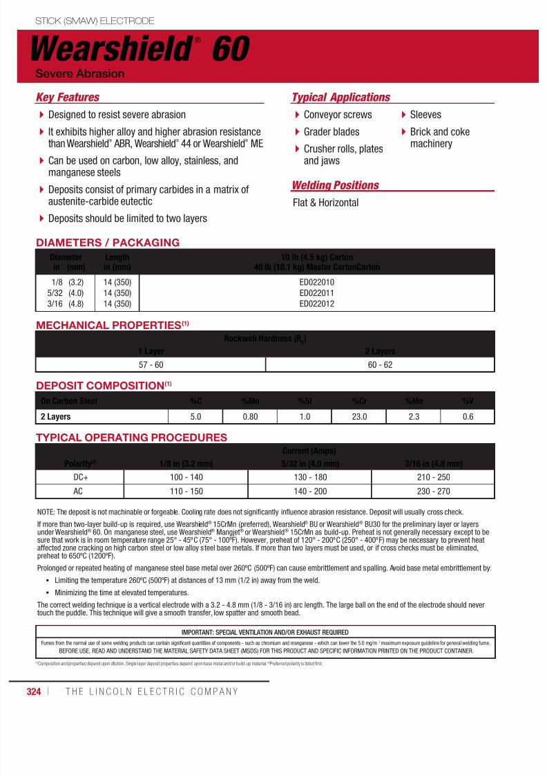
7/18/2019 c110 - Lincoln Electric Consumables 2014
http://slidepdf.com/reader/full/c110-lincoln-electric-consumables-2014 324/511324 ı T H E L I N C O L N E L E C T R I C C O M P A N Y
Wearshield ®
60 STICK (SMAW) ELECTRODE
Welding Positions
Typical Applications
Flat & Horizontal
Conveyor screws
Grader blades Crusher rolls, platesand jaws
Sleeves
Brick and cokemachinery
Designed to resist severe abrasion
It exhibits higher alloy and higher abrasion resistancethan Wearshield
®
ABR, Wearshield®
44 or Wearshield®
ME
Can be used on carbon, low alloy, stainless, andmanganese steels
Deposits consist of primary carbides in a matrix ofaustenite-carbide eutectic
Deposits should be limited to two layers
Severe Abrasion
Key Features
DIAMETERS / PACKAGING
Diameter Length 10 lb (4.5 kg) Carton
40 lb (18.1 kg) Master CartonCartonin (mm) in (mm)
1/8
5/32
3/16
(3.2)
(4.0)
(4.8)
14 (350)
14 (350)
14 (350)
ED022010
ED022011
ED022012
MECHANICAL PROPERTIES(1)
Rockwell Hardness (RC)
1 Layer 2 Layers
57 - 60 60 - 62
DEPOSIT COMPOSITION(1)
On Carbon Steel %C %Mn %Si %Cr %Mo %V
2 Layers 5.0 0.80 1.0 23.0 2.3 0.6
(1)Composition and properties depend upon dilution. Single layer deposit properties depend upon base metal and/or build-up material. (2)Preferred polarity is listed first.
TYPICAL OPERATING PROCEDURES
Current (Amps)
Polarity(2) 1/8 in (3.2 mm) 5/32 in (4.0 mm) 3/16 in (4.8 mm)
DC+ 100 - 140 130 - 180 210 - 250
AC 110 - 150 140 - 200 230 - 270
NOTE: The deposit is not machinable or forgeable. Cooling rate does not significantly influence abrasion resistance. Deposit will usually cross check.
If more than two-layer build-up is required, use Wearshield® 15CrMn (preferred), Wearshield® BU or Wearshield® BU30 for the preliminary layer or layersunder Wearshield® 60. On manganese steel, use Wearshield® Mangjet® or Wearshield® 15CrMn as build-up. Preheat is not generally necessary except to besure that work is in room temperature range 25° - 45ºC (75° - 100ºF). However, preheat of 120° - 200ºC (250° - 400ºF) may be necessary to prevent heataffected zone cracking on high carbon steel or low alloy steel base metals. If more than two layers must be used, or if cross checks must be eliminated,preheat to 650ºC (1200ºF).
Prolonged or repeated heating of manganese steel base metal over 260ºC (500ºF) can cause embrittlement and spalling. Avoid base metal embrittlement by:
• Limiting the temperature 260ºC (500ºF) at distances of 13 mm (1/2 in) away from the weld.
• Minimizing the time at elevated temperatures.
The correct welding technique is a vertical electrode with a 3.2 - 4.8 mm (1/8 - 3/16 in) arc length. The large ball on the end of the electrode should nevertouch the puddle. This technique will give a smooth transfer, low spatter and smooth bead.
IMPORTANT: SPECIAL VENTILATION AND/OR EXHAUST REQUIRED
Fumes from the normal use of some welding products can contain significant quantities of components - such as chromium and manganese - which can lower the 5.0 mg/m 3 maximum exposure guideline for general welding fume.
BEFORE USE, READ AND UNDERSTAND THE MATERIAL SAFETY DATA SHEET (MSDS) FOR THIS PRODUCT AND SPECIFIC INFORMATION PRINTED ON THE PRODUCT CONTAINER.

7/18/2019 c110 - Lincoln Electric Consumables 2014
http://slidepdf.com/reader/full/c110-lincoln-electric-consumables-2014 325/511W E L D I N G C O N S U M A B L E S C A TA L O G ı 325
Blue Max ®
2100STICK (SMAW) ELECTRODE
Welding Positions
Typical Applications
All, except vertical down
High carbon, low alloy, high strength, manganese steels
Base for hardfacing or stainless steel cladding
High resistance to cracking
High strength Designed for joining difficult to weld steel
Maintenance & Repair
Key Features
DIAMETERS / PACKAGING
Diameter Length 10 lb (4.5 kg)
Easy Open Canmm (in) in (mm)2.5
3.2
(3/32)
(1/8)
14 (350)
14 (350)
ED032298
ED032299
TYPICAL OPERATING PROCEDURES
Current (Amps)
Polarity(2) 2.4 mm (3/32 in) 3.2 mm (1/8 in)
DC+ 40 -80 75 - 110
AC 40 -80 75 - 110
(1)Composition and properties depend upon dilution. Single layer deposit properties depend upon base metal and/or build-up material. (2)Preferred polarity is listed first.
MECHANICAL PROPERTIES(1)
Yield Strength(2)
MPa (ksi)Tensile Strength
MPa (ksi)Elongation
%Ferrite
Number
Test Results 670 (97) 805 (117) 22 > 50

7/18/2019 c110 - Lincoln Electric Consumables 2014
http://slidepdf.com/reader/full/c110-lincoln-electric-consumables-2014 326/511
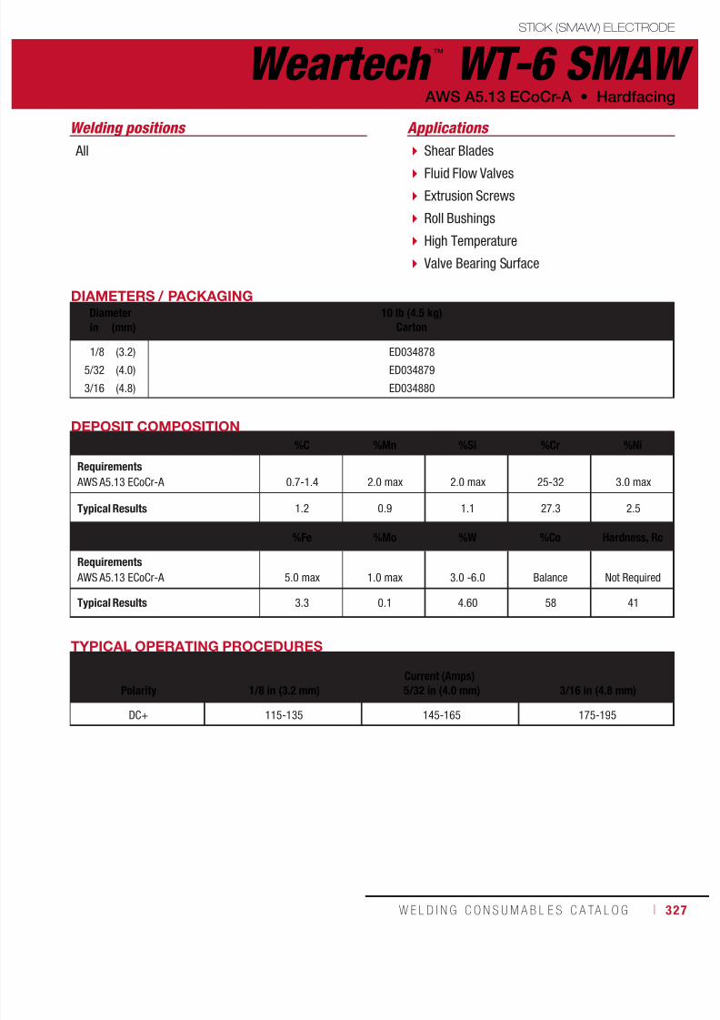
7/18/2019 c110 - Lincoln Electric Consumables 2014
http://slidepdf.com/reader/full/c110-lincoln-electric-consumables-2014 327/511W E L D I N G C O N S U M A B L E S C A TA L O G ı 327
Weartech ™
WT-6 SMAWSTICK (SMAW) ELECTRODE
AWS A5.13 ECoCr-A • Hardfacing
Shear Blades
Fluid Flow Valves Extrusion Screws
Roll Bushings
High Temperature
Valve Bearing Surface
Applications
DIAMETERS / PACKAGINGDiameter 10 lb (4.5 kg)
Cartonin (mm)
1/8
5/32
3/16
(3.2)
(4.0)
(4.8)
ED034878
ED034879
ED034880
DEPOSIT COMPOSITION
%C %Mn %Si %Cr %Ni
Requirements AWS A5.13 ECoCr-A 0.7-1.4 2.0 max 2.0 max 25-32 3.0 max
Typical Results 1.2 0.9 1.1 27.3 2.5
%Fe %Mo %W %Co Hardness, Rc
Requirements AWS A5.13 ECoCr-A 5.0 max 1.0 max
3.0 -6.0 Balance Not Required
Typical Results 3.3 0.1 4.60 58 41
All
Welding positions
TYPICAL OPERATING PROCEDURES
Current (Amps)Polarity 1/8 in (3.2 mm) 5/32 in (4.0 mm) 3/16 in (4.8 mm)
DC+ 115-135 145-165 175-195
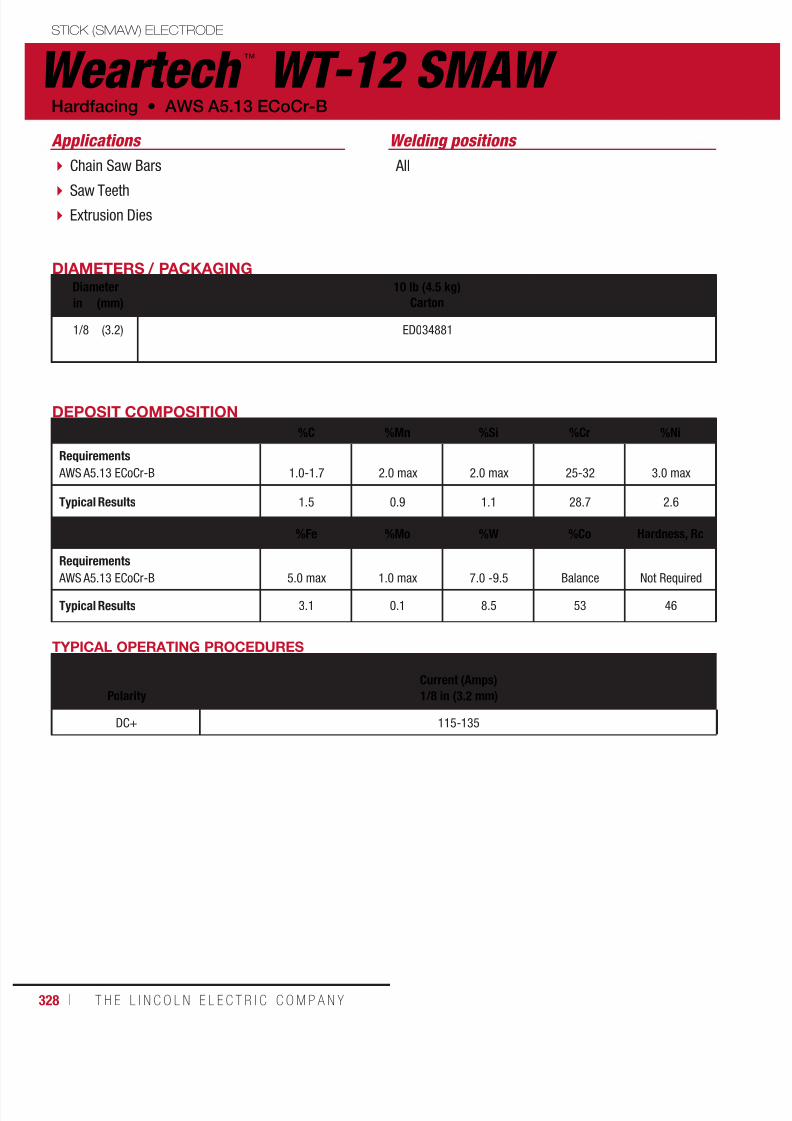
7/18/2019 c110 - Lincoln Electric Consumables 2014
http://slidepdf.com/reader/full/c110-lincoln-electric-consumables-2014 328/511328 ı T H E L I N C O L N E L E C T R I C C O M P A N Y
Weartech ™
WT-12 SMAWSTICK (SMAW) ELECTRODE
Hardfacing • AWS A5.13 ECoCr-B
Chain Saw Bars
Saw Teeth Extrusion Dies
Applications
DIAMETERS / PACKAGINGDiameter 10 lb (4.5 kg)
Cartonin (mm)
1/8 (3.2) ED034881
DEPOSIT COMPOSITION
%C %Mn %Si %Cr %Ni
Requirements AWS A5.13 ECoCr-B 1.0-1.7 2.0 max 2.0 max 25-32 3.0 max
Typical Results 1.5 0.9 1.1 28.7 2.6
%Fe %Mo %W %Co Hardness, Rc
Requirements
AWS A5.13 ECoCr-B 5.0 max 1.0 max 7.0 -9.5 Balance Not Required
Typical Results 3.1 0.1 8.5 53 46
All
Welding positions
TYPICAL OPERATING PROCEDURES
Current (Amps)
Polarity 1/8 in (3.2 mm)
DC+ 115-135

7/18/2019 c110 - Lincoln Electric Consumables 2014
http://slidepdf.com/reader/full/c110-lincoln-electric-consumables-2014 329/511W E L D I N G C O N S U M A B L E S C A TA L O G ı 329
Weartech ™
WT-21 SMAWSTICK (SMAW) ELECTRODE
AWS A5.13 ECoCr-E • Hardfacing
Steam Valves
Hot Shears Chemical andPetrochemical Valves
Cavation Repair
Forging Dies
Applications
DIAMETERS / PACKAGINGDiameter 10 lb (4.5 kg)
Cartonin (mm)
1/8
5/32
3/16
(3.2)
(4.0)
(4.8)
ED034882
ED034883
ED034884
DEPOSIT COMPOSITION
%C %Mn %Si %Cr %Ni
Requirements AWS A5.13 ECoCr-E 0.15-0.40 1.5 max 2.0 max 24-29 2.0 -4.0
Typical Results 0.23 0.8 0.8 27.7 2.8
%Fe %Mo %W %Co Hardness, Rc
Requirements AWS A5.13 ECoCr-E 5.0 max 4.5-6.5 0.50 max Balance Not Required
Typical Results 2.4 5.5 0.05 59 28
All
Welding positions
TYPICAL OPERATING PROCEDURES
Current (Amps)Polarity 1/8 in (3.2 mm) 5/32 in (4.0 mm) 3/16 in (4.8 mm)
DC+ 115-135 145-165 175-195
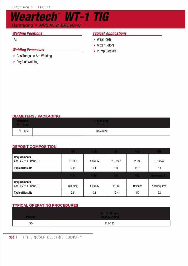
7/18/2019 c110 - Lincoln Electric Consumables 2014
http://slidepdf.com/reader/full/c110-lincoln-electric-consumables-2014 330/511330 ı T H E L I N C O L N E L E C T R I C C O M P A N Y
Weartech ™
WT-1 TIG TIG (GTAW) CUT LENGTHS
Hardfacing • AWS A5.21 ERCoCr-C
Wear Pads
Mixer Rotors Pump Sleeves
Typical Applications
DIAMETERS / PACKAGINGDiameter 10 lb (4.5 kg)
Cartonin (mm)
1/8 (3.2) ED034870
DEPOSIT COMPOSITION
%C %Mn %Si %Cr %Ni
Requirements AWS A5.21 ERCoCr-C 2.0-3.0 1.0 max 2.0 max 26-33 3.0 max
Typical Results 2.2 0.1 1.0 29.5 2.4
%Fe %Mo %W %Co Hardness, Rc
Requirements AWS A5.21 ERCoCr-C 3.0 max 1.0 max 11-14 Balance
Not Required
Typical Results 2.5 0.1 12.4 50 52
All
Gas Tungsten Arc Welding
Oxyfuel Welding
Welding Positions
Welding Processes
TYPICAL OPERATING PROCEDURES
Current (Amps)Polarity 1/8 in (3.2 mm)
DC- 115-135

7/18/2019 c110 - Lincoln Electric Consumables 2014
http://slidepdf.com/reader/full/c110-lincoln-electric-consumables-2014 331/511W E L D I N G C O N S U M A B L E S C A TA L O G ı 331
Weartech ™
WT-6 TIG TIG (GTAW) CUT LENGTHS
AWS A5.21 ERCoCr-A • Hardfacing
Shear Blades
Fluid Flow Valves Extrusion Screws
Roll Bushings
High Temperature
Valve Bearing Surface
Gas Tungsten Arc Welding
Oxyfuel Welding
Typical Applications
Welding Processes
DIAMETERS / PACKAGINGDiameter 10 lb (4.5 kg)
Cartonin (mm)
1/8
5/32
3/16
(3.2)
(4.0)
(4.8)
ED034871
ED034872
ED034873
DEPOSIT COMPOSITION
%C %Mn %Si %Cr %Ni
Requirements AWS A5.21 ERCoCr-A 0.9-1.4 1.0 max 2.0 max 26-32 3.0 max
Typical Results 1.1 0.1 1.3 28.2 2.5
%Fe %Mo %W %Co Hardness, Rc
Requirements AWS A5.21 ERCoCr-A 3.0 max 1.0 max 3.0 -6.0 Balance Not Required
Typical Results 2.5 0.1 4.7 59 42
All
Welding positions
TYPICAL OPERATING PROCEDURES
Current (Amps)Polarity 1/8 in (3.2 mm) 5/32 in (4.0 mm) 3/16 in (4.8 mm)
DC- 115-135 145-165 175-195
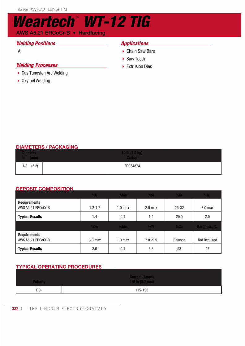
7/18/2019 c110 - Lincoln Electric Consumables 2014
http://slidepdf.com/reader/full/c110-lincoln-electric-consumables-2014 332/511332 ı T H E L I N C O L N E L E C T R I C C O M P A N Y
Weartech ™
WT-12 TIG TIG (GTAW) CUT LENGTHS
AWS A5.21 ERCoCr-B • Hardfacing
Chain Saw Bars
Saw Teeth Extrusion Dies
Gas Tungsten Arc Welding
Oxyfuel Welding
Applications
Welding Processes
DIAMETERS / PACKAGINGDiameter 10 lb (4.5 kg)
Cartonin (mm)
1/8 (3.2) ED034874
DEPOSIT COMPOSITION
%C %Mn %Si %Cr %Ni
Requirements AWS A5.21 ERCoCr-B 1.2-1.7 1.0 max 2.0 max 26-32 3.0 max
Typical Results 1.4 0.1 1.4 29.5 2.5
%Fe %Mo %W %Co Hardness, Rc
Requirements AWS A5.21 ERCoCr-B 3.0 max 1.0 max 7.0 -9.5 Balance Not Required
Typical Results 2.6 0.1 8.8 53 47
All
Welding Positions
TYPICAL OPERATING PROCEDURES
Current (Amps)Polarity 1/8 in (3.2 mm)
DC- 115-135
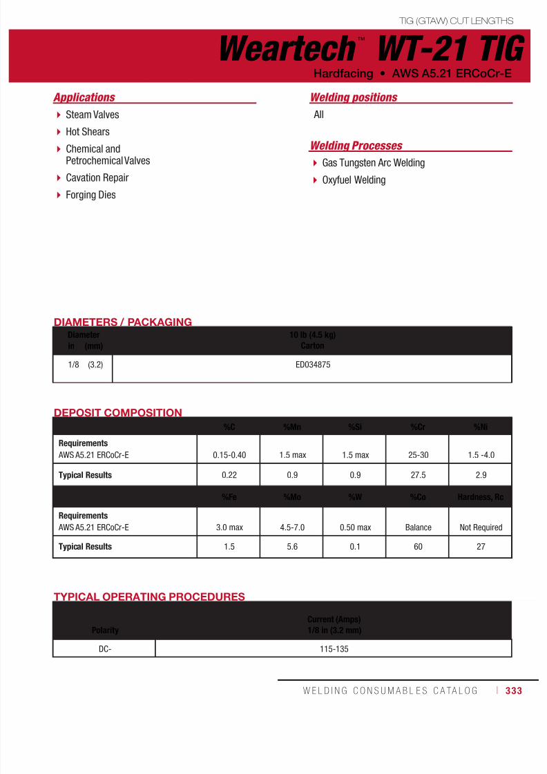
7/18/2019 c110 - Lincoln Electric Consumables 2014
http://slidepdf.com/reader/full/c110-lincoln-electric-consumables-2014 333/511W E L D I N G C O N S U M A B L E S C A TA L O G ı 333
Weartech ™
WT-21 TIG TIG (GTAW) CUT LENGTHS
Steam Valves
Hot Shears Chemical andPetrochemical Valves
Cavation Repair
Forging Dies
Applications
DIAMETERS / PACKAGINGDiameter 10 lb (4.5 kg)
Cartonin (mm)
1/8 (3.2) ED034875
DEPOSIT COMPOSITION
%C %Mn %Si %Cr %Ni
Requirements AWS A5.21 ERCoCr-E 0.15-0.40 1.5 max 1.5 max 25-30 1.5 -4.0
Typical Results 0.22 0.9 0.9 27.5 2.9
%Fe %Mo %W %Co Hardness, Rc
Requirements
AWS A5.21 ERCoCr-E 3.0 max 4.5-7.0 0.50 max Balance Not Required
Typical Results 1.5 5.6 0.1 60 27
All
Welding positions
Gas Tungsten Arc Welding
Oxyfuel Welding
Welding Processes
Hardfacing • AWS A5.21 ERCoCr-E
TYPICAL OPERATING PROCEDURES
Current (Amps)Polarity 1/8 in (3.2 mm)
DC- 115-135
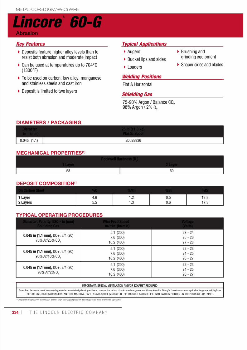
7/18/2019 c110 - Lincoln Electric Consumables 2014
http://slidepdf.com/reader/full/c110-lincoln-electric-consumables-2014 334/511334 ı T H E L I N C O L N E L E C T R I C C O M P A N Y
IMPORTANT: SPECIAL VENTILATION AND/OR EXHAUST REQUIRED
Fumes from the normal use of some welding products can contain significant quantities of components - such as chromium and manganese - which can lower the 5.0 mg/m 3 maximum exposure guideline for general welding fume.
BEFORE USE, READ AND UNDERSTAND THE MATERIAL SAFETY DATA SHEET (MSDS) FOR THIS PRODUCT AND SPECIFIC INFORMATION PRINTED ON THE PRODUCT CONTAINER.
Lincore ®
60-G METAL-CORED (GMAW-C) WIRE
Welding Positions
Typical Applications
Flat & Horizontal
Augers
Bucket lips and sides Loaders
Brushing andgrinding equipment
Shaper sides and blades
Deposits feature higher alloy levels than toresist both abrasion and moderate impact
Can be used at temperatures up to 704°C(1300°F)
To be used on carbon, low alloy, manganeseand stainless steels and cast iron
Deposit is limited to two layers
Abrasion
Key Features
DIAMETERS / PACKAGING
Diameter 25 lb (11.3 kg)Plastic Spoolin (mm)
0.045 (1.1) ED029936
Shielding Gas
75-90% Argon / Balance CO2
98% Argon / 2% O2
DEPOSIT COMPOSITION(1)
On Carbon Steel %C %Mn %Si %Cr
1 Layer2 Layers
4.6
5.5
1.2
1.3
0.5
0.6
13.8
17.3
(1) Composition and properties depend upon dilution. Single layer deposit properties depend upon base metal and/or build-up material.
MECHANICAL PROPERTIES(1)
Rockwell Hardness (RC)
1 Layer 2 Layer
58 60
TYPICAL OPERATING PROCEDURES
Diameter, Polarity, ESO - in (mm)Shielding Gas
Wire Feed Speed Voltage(Volts)m/min (in/min)
0.045 in (1.1 mm), DC+, 3/4 (20)
75% Ar/25% CO2
5.1
7.610.2
(200)
(300)(400)
23 - 24
25 - 2627 - 28
0.045 in (1.1 mm), DC+, 3/4 (20)
90% Ar/10% CO2
5.1
7.6
10.2
(200)
(300)
(400)
22 - 23
24 - 25
26 - 27
0.045 in (1.1 mm), DC+, 3/4 (20)
98% Ar/2% O2
5.1
7.6
10.2
(200)
(300)
(400)
22 - 23
24 - 25
26 - 27
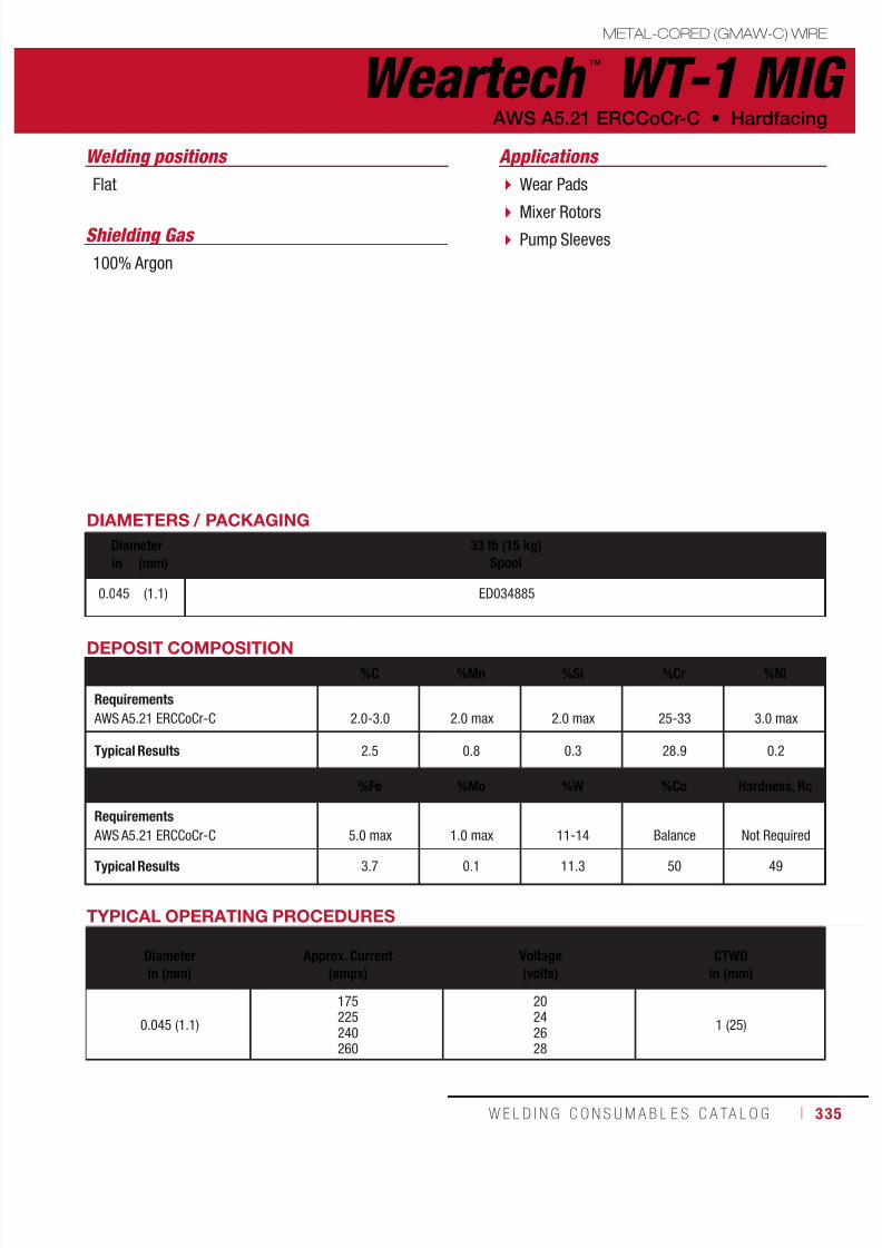
7/18/2019 c110 - Lincoln Electric Consumables 2014
http://slidepdf.com/reader/full/c110-lincoln-electric-consumables-2014 335/511W E L D I N G C O N S U M A B L E S C A TA L O G ı 335
METAL-CORED (GMAW-C) WIRE
Weartech ™
WT-1 MIG AWS A5.21 ERCCoCr-C • Hardfacing
Wear Pads
Mixer Rotors Pump Sleeves
Flat
100% Argon
ApplicationsWelding positions
Shielding Gas
DIAMETERS / PACKAGING
Diameter 33 lb (15 kg)Spoolin (mm)
0.045 (1.1) ED034885
DEPOSIT COMPOSITION
%C %Mn %Si %Cr %Ni
Requirements AWS A5.21 ERCCoCr-C 2.0-3.0 2.0 max 2.0 max 25-33 3.0 max
Typical Results 2.5 0.8 0.3 28.9 0.2
%Fe %Mo %W %Co Hardness, Rc
Requirements AWS A5.21 ERCCoCr-C 5.0 max 1.0 max 11-14 Balance Not Required
Typical Results 3.7 0.1 11.3 50 49
TYPICAL OPERATING PROCEDURES
Diameter
Approx. Current
Voltage
CTWD
in (mm) (amps) (volts) in (mm)
0.045 (1.1)
175225240260
20242628
1 (25)

7/18/2019 c110 - Lincoln Electric Consumables 2014
http://slidepdf.com/reader/full/c110-lincoln-electric-consumables-2014 336/511336 ı T H E L I N C O L N E L E C T R I C C O M P A N Y
Weartech ™
WT-6 MIG METAL-CORED (GMAW-C) WIRE
Hardfacing • AWS A5.21 ERCCoCr-A
Shear Blades
Fluid Flow Valves Extrusion Screws
Roll Bushings
High Temperature
Valve Bearing Surface
Applications
DIAMETERS / PACKAGINGDiameter 33 lb (15 kg)
Spoolin (mm)
0.045
1/16
(1.1)
(1.6)
ED034886
ED034887
DEPOSIT COMPOSITION
%C %Mn %Si %Cr %NiRequirements AWS A5.21 ERCCoCr-A 0.7-1.4 2.0 max 2.0 max 25-32 3.0 max
Typical Results 1.2 0.8 0.5 28.2 0.3
%Fe %Mo %W %Co Hardness, Rc
Requirements AWS A5.21 ERCCoCr-A 5.0 max 1.0 max 3.0 -6.0 Balance Not Required
Typical Results 3.9 0.1 4.1 58 40
Flat
100% Argon
Welding positions
Shielding Gas
TYPICAL OPERATING PROCEDURES
Diameter
Approx. Current
Voltage
CTWDin (mm) (amps) (volts) in (mm)
0.045 (1.1)
175225240260
20242628
1 (25)
1/16 (1.6)280300
2628
1 (25)

7/18/2019 c110 - Lincoln Electric Consumables 2014
http://slidepdf.com/reader/full/c110-lincoln-electric-consumables-2014 337/511W E L D I N G C O N S U M A B L E S C A TA L O G ı 337
METAL-CORED (GMAW-C) WIRE
Weartech ™
WT-12 MIG AWS A5.21 ERCCoCr-B • Hardfacing
Chain Saw Bars
Saw Teeth Extrusion Dies
Applications
DIAMETERS / PACKAGINGDiameter 33 lb (15 kg)
Spoolin (mm)
0.045
1/16
(1.1)
(1.6)
ED034888
ED034889
DEPOSIT COMPOSITION
%C %Mn %Si %Cr %Ni
Requirements AWS A5.21 ERCCoCr-B 1.2-2.0 2.0 max 2.0 max 25-32 3.0 max
Typical Results 1.5 0.9 1.0 27.4 0.2
%Fe %Mo %W %Co Hardness, Rc
Requirements AWS A5.21 ERCCoCr-B 5.0 max 1.0 max 7-10 Balance Not Required
Typical Results 3.9 0.1 8.4 53 45
Flat
100% Argon
Welding positions
Shielding Gas
TYPICAL OPERATING PROCEDURES
Diameter
Approx. Current
Voltage
CTWD
in (mm) (amps) (volts) in (mm)
0.045 (1.2)
175225240260
20242628
1 (25)
1/16 (1.6)280300
2628
1 (25)

7/18/2019 c110 - Lincoln Electric Consumables 2014
http://slidepdf.com/reader/full/c110-lincoln-electric-consumables-2014 338/511338 ı T H E L I N C O L N E L E C T R I C C O M P A N Y
Weartech ™
WT-21 MIG METAL-CORED (GMAW-C) WIRE
Hardfacing • AWS A5.21 ERCCoCr-E
Steam Valves
Hot Shears Chemical andPetrochemical Valves
Cavation Repair
Forging Dies
Applications
DIAMETERS / PACKAGINGDiameter 33 lb (15 kg)
Spoolin (mm)
0.045
1/16
(1.1)
(1.6)
EDO34890
EDO34891
DEPOSIT COMPOSITION
%C %Mn %Si %Cr %Ni
Requirements AWS A5.21 ERCCoCr-E 0.15-0.40 2.0 max 1.5 max 25-30 1.5 -4.0
Typical Results 0.25 0.7 0.6 27.5 2.1
%Fe %Mo %W %Co Hardness, Rc
Requirements AWS A5.21 ERCCoCr-E 5.0 max 4.5-7.0 0.50 max Balance Not Required
Typical Results 3.9 5.5 0.1 59 24
Flat
100% Argon
Welding positions
Shielding Gas
TYPICAL OPERATING PROCEDURES
Diameter
Approx. Current
Voltage
CTWDin (mm) (amps) (volts) in (mm)
0.045 (1.1)
175225240260
20242628
1 (25)
1/16 (1.6)280300
2628
1 (25)

7/18/2019 c110 - Lincoln Electric Consumables 2014
http://slidepdf.com/reader/full/c110-lincoln-electric-consumables-2014 339/511W E L D I N G C O N S U M A B L E S C A TA L O G ı 339
IMPORTANT: SPECIAL VENTILATION AND/OR EXHAUST REQUIRED
Fumes from the normal use of some welding products can contain significant quantities of components - such as chromium and manganese - which can lower the 5.0 mg/m 3 maximum exposure guideline for general welding fume.
BEFORE USE, READ AND UNDERSTAND THE MATERIAL SAFETY DATA SHEET (MSDS) FOR THIS PRODUCT AND SPECIFIC INFORMATION PRINTED ON THE PRODUCT CONTAINER.
Lincore ®
30-SMETAL-CORED SUBMERGED ARC (SAW) ELECTRODE
Typical Applications
For Build-upTractor rollers
Trunnions
Idlers
Crane wheels
For Hardfacing Shafts
Track rails
Idlers
Intended for build-up before final overlay,and as a final surface for metal-to-metalwear with moderate impact
For automatic and semiautomatic operationon mild and low alloy steels
Good resistance to cross checking
Unlimited deposit thickness with properpreheat and interpass temperatures andprocedures
Build-Up
Key Features
Recommended Flux
Primary Flux801
Secondary Flux(1)
802, 860
DIAMETERS / PACKAGING
Diameter 50 lb (22.7 kg)Coil
600 lb (272 kg)Speed-Feed® Drumin (mm)
3/32
1/8
(2.4)
(3.2)
ED011200
ED015889
ED011199
ED015891
(1) 802 and 860 standard flux are not sized for semiautomatic applications; however, they can be ordered in special sizing by
contacting your Lincoln Electric representative.
DEPOSIT COMPOSITION(1)
%C %Mn %Si %Mo
6 Layers - Under 801 or 8026 Layers - Under 860
0.11
0.11
2.5
2.7
0.40
0.60
0.50
0.50
(1) Composition and properties depend upon dilution. Single layer deposit properties depend upon base metal and/or build-up material.
MECHANICAL PROPERTIES(1)
Rockwell Hardness (RC)
6 Layers - Under 801 or 802 Flux 6 Layers - Under 860 Flux27 27
TYPICAL OPERATING PROCEDURES
Diameter, PolarityESO - in (mm) Wire Feed Speed Voltage(Volts) Approx. Current(Amps) Deposition Ratem/min (in/min) kg/hr (lb/hr)
3/32 in (2.4 mm), DC+
1-1/2 (38)
1.5
3.0
4.6
(60)
(120)
(180)
26
27
28
220
360
500
2.7
5.2
7.7
(6.0)
(11.5)
(17.0)
1/8 in (3.2 mm), DC+
1-5/8 (40)
1.3
2.0
2.8
(50)
(80)
(110)
27
28
28
310
450
600
3.4
6.4
9.1
(7.5)
(14.0)
(20.0)
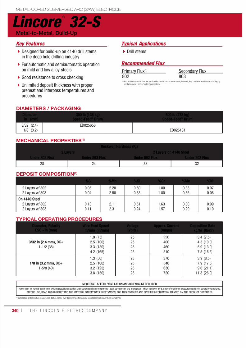
7/18/2019 c110 - Lincoln Electric Consumables 2014
http://slidepdf.com/reader/full/c110-lincoln-electric-consumables-2014 340/511340 ı T H E L I N C O L N E L E C T R I C C O M P A N Y
Drill stems
Lincore ®
32-S
Typical Applications
Metal-to-Metal, Build-Up
DIAMETERS / PACKAGING
Diameter 300 lb (136 kg)
Speed-Feed® Drum
600 lb (272 kg)
Speed-Feed® Drumin (mm)3/32
1/8
(2.4)
(3.2)
ED025656
ED025131
Recommended Flux
Primary Flux(1)
802Secondary Flux803
MECHANICAL PROPERTIES(1)
Rockwell Hardness (RC)
2 Layers 2 Layers on 4140 Steel
Under 802 Flux Under 803 Flux Under 802 Flux Under 803 Flux
28 24 33 32
DEPOSIT COMPOSITION(1)
%C %Mn %Si %Cr %Mo %Ni
2 Layers w/ 802
2 Layers w/ 803
0.05
0.04
2.20
2.50
0.60
0.33
1.80
1.80
0.33
0.35
0.07
0.08
On 4140 Steel 2 Layers w/ 802
2 Layers w/ 803
0.13
0.11
2.11
2.31
0.51
0.24
1.63
1.57
0.30
0.29
0.09
0.10
(1) Composition and properties depend upon dilution. Single layer deposit properties depend upon base metal and/or build-up material.
TYPICAL OPERATING PROCEDURES
Diameter, PolarityESO - in (mm)
Wire Feed Speed Voltage(Volts)
Approx. Current(Amps)
Deposition Ratem/min (in/min) kg/hr (lb/hr)
3/32 in (2.4 mm), DC+
1-1/2 (38)
1.92.5
3.3
4.2
(75)(100)
(130)
(165)
2525
25
25
350400
460
510
3.44.5
5.9
7.5
(7.5)(10.0)
(13.0)
(16.5)
1/8 in (3.2 mm), DC+
1-5/8 (40)
1.3
2.5
3.2
3.8
(50)
(100)
(125)
(150)
28
28
28
28
370
540
630
720
3.9
7.9
9.6
11.8
(8.5)
(17.5)
(21.1)
(26.0)
IMPORTANT: SPECIAL VENTILATION AND/OR EXHAUST REQUIRED
Fumes from the normal use of some welding products can contain significant quantities of components - such as chromium and manganese - which can lower the 5.0 mg/m 3 maximum exposure guideline for general welding fume.
BEFORE USE, READ AND UNDERSTAND THE MATERIAL SAFETY DATA SHEET (MSDS) FOR THIS PRODUCT AND SPECIFIC INFORMATION PRINTED ON THE PRODUCT CONTAINER.
(1) 802 and 860 standard flux are not sized for semiautomatic applications; however, they can be ordered in special sizing by
contacting your Lincoln Electric representative.
METAL-CORED SUBMERGED ARC (SAW) ELECTRODE
Designed for build-up on 4140 drill stemsin the deep hole drilling industry
For automatic and semiautomatic operationon mild and low alloy steels
Good resistance to cross checking
Unlimited deposit thickness with properpreheat and interpass temperatures andprocedures
Key Features
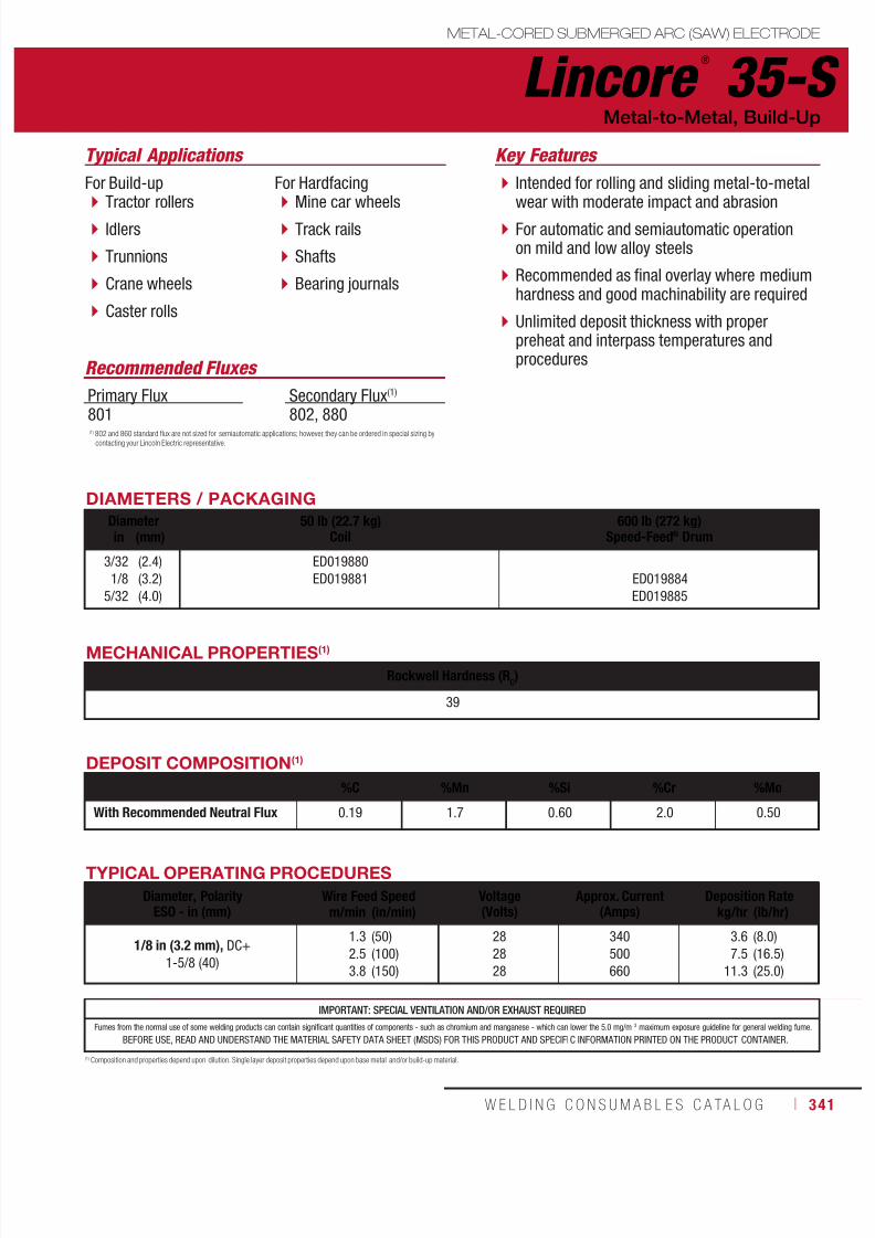
7/18/2019 c110 - Lincoln Electric Consumables 2014
http://slidepdf.com/reader/full/c110-lincoln-electric-consumables-2014 341/511W E L D I N G C O N S U M A B L E S C A TA L O G ı 341
IMPORTANT: SPECIAL VENTILATION AND/OR EXHAUST REQUIRED
Fumes from the normal use of some welding products can contain significant quantities of components - such as chromium and manganese - which can lower the 5.0 mg/m 3 maximum exposure guideline for general welding fume.
BEFORE USE, READ AND UNDERSTAND THE MATERIAL SAFETY DATA SHEET (MSDS) FOR THIS PRODUCT AND SPECIFIC INFORMATION PRINTED ON THE PRODUCT CONTAINER.
Lincore ®
35-SMETAL-CORED SUBMERGED ARC (SAW) ELECTRODE
Typical Applications
For Build-up Tractor rollers
Idlers
Trunnions
Crane wheels
Caster rolls
For Hardfacing Mine car wheels
Track rails
Shafts
Bearing journals
Metal-to-Metal, Build-Up
Recommended Fluxes
Primary Flux
801
Secondary Flux(1)
802, 880
DIAMETERS / PACKAGING
Diameter 50 lb (22.7 kg)Coil
600 lb (272 kg)Speed-Feed® Drumin (mm)
3/32
1/8
5/32
(2.4)
(3.2)
(4.0)
ED019880
ED019881 ED019884
ED019885
MECHANICAL PROPERTIES(1)
Rockwell Hardness (RC)
39
DEPOSIT COMPOSITION(1)
%C %Mn %Si %Cr %Mo
With Recommended Neutral Flux 0.19 1.7 0.60 2.0 0.50
(1) Composition and properties depend upon dilution. Single layer deposit properties depend upon base metal and/or build-up material.
TYPICAL OPERATING PROCEDURES
Diameter, PolarityESO - in (mm)
Wire Feed Speed Voltage(Volts)
Approx. Current(Amps)
Deposition Ratem/min (in/min) kg/hr (lb/hr)
1/8 in (3.2 mm), DC+
1-5/8 (40)
1.3
2.5
3.8
(50)
(100)
(150)
28
28
28
340
500
660
3.6
7.5
11.3
(8.0)
(16.5)
(25.0)
(1) 802 and 860 standard flux are not sized for semiautomatic applications; however, they can be ordered in special sizing by
contacting your Lincoln Electric representative.
Intended for rolling and sliding metal-to-metalwear with moderate impact and abrasion
For automatic and semiautomatic operationon mild and low alloy steels
Recommended as final overlay where mediumhardness and good machinability are required
Unlimited deposit thickness with properpreheat and interpass temperatures andprocedures
Key Features

7/18/2019 c110 - Lincoln Electric Consumables 2014
http://slidepdf.com/reader/full/c110-lincoln-electric-consumables-2014 342/511342 ı T H E L I N C O L N E L E C T R I C C O M P A N Y
Lincore ®
40-S METAL-CORED SUBMERGED ARC (SAW) ELECTRODE
Typical Applications
Idlers
Drive sprockets
Mine car wheels
Metal-to-Metal
DIAMETERS / PACKAGING
Diameter 50 lb (22.7 kg)Coil
600 lb (272 kg)Speed-Feed® Drumin (mm)
1/8 (3.2) ED015892 ED015909
Recommended Fluxes
Primary Flux801
Secondary Flux(1)
802, 880
DEPOSIT COMPOSITION(1)
%C %Mn %Si %Cr %Mo
With Recommended Neutral Flux 0.12 2.75 3.30 0.50 0.85
(1) Composition and properties depend upon dilution. Single layer deposit properties depend upon base metal and/or build-up material.
MECHANICAL PROPERTIES(1)
Rockwell Hardness (RC)
3 or More Layers After 2 Hours Post Weld Heat Treat
39 - 42
IMPORTANT: SPECIAL VENTILATION AND/OR EXHAUST REQUIRED
Fumes from the normal use of some welding products can contain significant quantities of components - such as chromium and manganese - which can lower the 5.0 mg/m 3 maximum exposure guideline for general welding fume.
BEFORE USE, READ AND UNDERSTAND THE MATERIAL SAFETY DATA SHEET (MSDS) FOR THIS PRODUCT AND SPECIFIC INFORMATION PRINTED ON THE PRODUCT CONTAINER.
TYPICAL OPERATING PROCEDURES
Diameter, PolarityESO - in (mm)
Wire Feed Speed Voltage(Volts)
Approx. Current(Amps)
Deposition Ratem/min (in/min) kg/hr (lb/hr)
1/8 in (3.2 mm), DC+
1-1/4 (32)
1.7
2.33.0
(65)
(90)(120)
27
2829
330
425525
4.4
5.97.8
(9.6)
(12.9)(17.3)
1/8 in (3.2 mm), DC+
2-1/2 (65)
2.0
2.8
3.7
(80)
(110)
(145)
29
30
31
345
425
500
5.2
7.3
9.4
(11.5)
(16.0)
(20.8)
1/8 in (3.2 mm), DC+
3-1/2 (90)
2.5
3.3
4.6
(100)
(130)
(180)
31
32
33
375
435
520
6.5
8.6
11.9
(14.3)
(18.9)
(26.1)
(1) 802 and 860 standard flux are not sized for semiautomatic applications; however, they can be ordered in special sizing by
contacting your Lincoln Electric representative.
Designed for rebuilding heavy equipmentundercarriages
Deposit is machinable and hot forgeable andresists rolling and sliding metal-to-metal wear
Use on carbon and low alloy steels for goodpuddle control on roundabout welding
Limited to 4 layers
Key Features

7/18/2019 c110 - Lincoln Electric Consumables 2014
http://slidepdf.com/reader/full/c110-lincoln-electric-consumables-2014 343/511W E L D I N G C O N S U M A B L E S C A TA L O G ı 343
IMPORTANT: SPECIAL VENTILATION AND/OR EXHAUST REQUIRED
Fumes from the normal use of some welding products can contain significant quantities of components - such as chromium and manganese - which can lower the 5.0 mg/m 3 maximum exposure guideline for general welding fume.
BEFORE USE, READ AND UNDERSTAND THE MATERIAL SAFETY DATA SHEET (MSDS) FOR THIS PRODUCT AND SPECIFIC INFORMATION PRINTED ON THE PRODUCT CONTAINER.
Lincore ®
42-SMETAL-CORED SUBMERGED ARC (SAW) ELECTRODE
Typical Applications
Tractor rollers
Tractor idlers
Track pads
Metal-to-Metal
DIAMETERS / PACKAGING
Diameter 300 lb (136 kg)Speed-Feed® Drum 600 lb (272 kg)Speed-Feed® Drumin (mm)
1/8 (3.2) ED029264 ED029161
Recommended Fluxes
Primary Flux801
Secondary Flux802, 880
MECHANICAL PROPERTIES(1)
Rockwell Hardness (RC)
1 Layer
40
DEPOSIT COMPOSITION(1)
With Recommended Neutral Flux %C %Mn %Si %Cr %Mo
1/8 in Diameter (3/4 in ESO) 1 Layer 2 Layers 4 Layers 6 Layers
0.140.120.110.10
2.132.703.333.51
0.340.390.440.46
1.452.222.953.20
0.430.660.840.80
1/8 in Diameter (1-5/8 in ESO)
1 Layer 2 Layers 4 Layers 6 Layers
0.140.130.130.13
2.493.053.413.55
0.330.420.470.51
2.022.963.153.31
0.600.840.991.06
(1) Composition and properties depend upon dilution. Single layer deposit properties depend upon base metal and/or build-up material.
TYPICAL OPERATING PROCEDURES
Diameter, PolarityESO - in (mm)
Wire Feed Speed Voltage(Volts)
Approx. Current(Amps)
Deposition Ratem/min (in/min) kg/hr (lb/hr)
1/8 in (3.2 mm), DC+3/4 (20)
1.32.53.2
(50)(100)(125)
272829
350565675
3.87.59.3
(8.4)(16.5)(20.5)
1/8 in (3.2 mm), DC+1-5/8 (40)
1.32.53.2
(50)(100)(125)
272829
325510605
3.87.59.4
(8.3)(16.6)(20.8)
(1) 802 and 880 standard flux are not sized for semiautomatic applications; however, they can be ordered in special sizing by
contacting your Lincoln Electric representative.
Designed for rebuilding heavy equipmentundercarriages
The deposit exhibits enhanced crackresistance and toughness compared toLincore® 40-S
Intended to resist rolling and slidingmetal-to-metal wear
For automatic and semiautomatic operation
Key Features
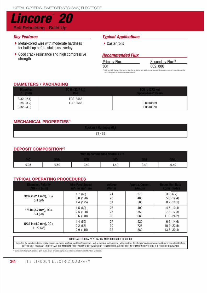
7/18/2019 c110 - Lincoln Electric Consumables 2014
http://slidepdf.com/reader/full/c110-lincoln-electric-consumables-2014 344/511344 ı T H E L I N C O L N E L E C T R I C C O M P A N Y
IMPORTANT: SPECIAL VENTILATION AND/OR EXHAUST REQUIRED
Fumes from the normal use of some welding products can contain significant quantities of components - such as chromium and manganese - which can lower the 5.0 mg/m 3 maximum exposure guideline for general welding fume.
BEFORE USE, READ AND UNDERSTAND THE MATERIAL SAFETY DATA SHEET (MSDS) FOR THIS PRODUCT AND SPECIFIC INFORMATION PRINTED ON THE PRODUCT CONTAINER.
Lincore ®
20 METAL-CORED SUBMERGED ARC (SAW) ELECTRODE
Typical Applications
Caster rolls
Recommended Flux
Roll Rebuilding - Build Up
Primary Flux801
Secondary Flux(1)
802, 880
DIAMETERS / PACKAGING
Diameter 50 lb (22.7 kg)Coil
600 lb (272 kg)Speed-Feed® Drumin (mm)
3/321/8
5/32
(2.4)(3.2)
(4.0)
EDS18565EDS18566 ED018569
EDS18570
DEPOSIT COMPOSITION(1)
With Recommended Neutral Flux
%C %Mn %Si %Cr %Ni %Mo
0.05 0.60 0.40 1.40 2.40 0.40
(1) Composition and properties depend upon dilution. Single layer deposit properties depend upon base metal and/or build-up material.
MECHANICAL PROPERTIES(1)
Rockwell Hardness (RC)
23 - 28
TYPICAL OPERATING PROCEDURES
Diameter, PolarityESO - in (mm)
Wire Feed Speed Voltage(Volts)
Approx. Current(Amps)
Deposition Ratem/min (in/min) kg/hr (lb/hr)
3/32 in (2.4 mm), DC+
3/4 (20)
1.7
3.0
4.4
(65)
(120)
(175)
24
28
31
270
400
500
3.0
5.6
8.2
(6.7)
(12.4)
(18.1)
1/8 in (3.2 mm), DC+
3/4 (20)
1.5
2.5
3.6
(60)
(100)
(140)
26
28
30
400
550
680
4.7
7.8
11.0
(10.4)
(17.3)
(24.2)
5/32 in (4.0 mm), DC+
1-1/2 (38)
1.4
2.2
2.9
(55)
(85)
(115)
27
30
32
520
725
880
6.6
10.2
13.8
(14.6)
(22.5)
(30.4)
(1) 802 and 860 standard flux are not sized for semiautomatic applications; however, they can be ordered in special sizing by
contacting your Lincoln Electric representative.
Metal-cored wire with moderate hardnessfor build-up before stainless overlay
Good crack resistance and high compressivestrength
Key Features

7/18/2019 c110 - Lincoln Electric Consumables 2014
http://slidepdf.com/reader/full/c110-lincoln-electric-consumables-2014 345/511W E L D I N G C O N S U M A B L E S C A TA L O G ı 345
METAL-CORED SUBMERGED ARC (SAW) ELECTRODE
Lincore ®
8620
Typical Applications
Caster rolls
Recommended Flux
Roll Rebuilding - Build Up
Primary Flux801
Secondary Flux(1)
802, 880
DIAMETERS / PACKAGING
Diameter 50 lb (22.7 kg)Coil
600 lb (272 kg)Speed-Feed® Drumin (mm)
1/8 (3.2) ED020788 ED020791
MECHANICAL PROPERTIES(1)
Rockwell Hardness (RC)16 - 20
IMPORTANT: SPECIAL VENTILATION AND/OR EXHAUST REQUIRED
Fumes from the normal use of some welding products can contain significant quantities of components - such as chromium and manganese - which can lower the 5.0 mg/m 3 maximum exposure guideline for general welding fume.
BEFORE USE, READ AND UNDERSTAND THE MATERIAL SAFETY DATA SHEET (MSDS) FOR THIS PRODUCT AND SPECIFIC INFORMATION PRINTED ON THE PRODUCT CONTAINER.
DEPOSIT COMPOSITION(1)
With Recommended Neutral Flux
%C %Mn %Si %Cr %Ni %Mo
0.09 0.80 0.30 0.45 0.55 0.15
(1) Composition and properties depend upon dilution. Single layer deposit properties depend upon base metal and/or build-up material.
TYPICAL OPERATING PROCEDURES
Diameter, PolarityESO - in (mm)
Wire Feed Speed Voltage(Volts)
Approx. Current(Amps)
Deposition Ratem/min (in/min) kg/hr (lb/hr)
1/8 in (3.2 mm), DC+
3/4 (20)
1.5
2.5
3.6
(60)
(100)
(140)
26
28
30
400
550
680
4.7
7.8
11.0
(10.4)
(17.3)
(24.2)
(1) 802 and 860 standard flux are not sized for semiautomatic applications; however, they can be ordered in special sizing by
contacting your Lincoln Electric representative.
Metal-cored wire for build-up on worn rolls
A little softer than Lincore® 20 for easiermachining
Key Features

7/18/2019 c110 - Lincoln Electric Consumables 2014
http://slidepdf.com/reader/full/c110-lincoln-electric-consumables-2014 346/511346 ı T H E L I N C O L N E L E C T R I C C O M P A N Y
IMPORTANT: SPECIAL VENTILATION AND/OR EXHAUST REQUIRED
Fumes from the normal use of some welding products can contain significant quantities of components - such as chromium and manganese - which can lower the 5.0 mg/m 3 maximum exposure guideline for general welding fume.
BEFORE USE, READ AND UNDERSTAND THE MATERIAL SAFETY DATA SHEET (MSDS) FOR THIS PRODUCT AND SPECIFIC INFORMATION PRINTED ON THE PRODUCT CONTAINER.
Lincore ®
4130 METAL-CORED SUBMERGED ARC (SAW) ELECTRODE
Typical Applications
Caster rolls
Roll Rebuilding - Build Up, Flame Hardenable
DIAMETERS / PACKAGING
Diameter 50 lb (22.7 kg)Coil
600 lb (272 kg)Speed-Feed® Drumin (mm)
3/32
1/8
(2.4)
(3.2)
ED015265
ED015266
ED015532
ED015405
Recommended Flux
Primary Flux801
Secondary Flux(1)
802, 880
MECHANICAL PROPERTIES(1)
Rockwell Hardness (RC)
17 - 21
DEPOSIT COMPOSITION(1)
With Recommended Neutral Flux
%C %Mn %Si %Cr %Mo
0.12 1.10 0.30 0.80 0.20
(1) Composition and properties depend upon dilution. Single layer deposit properties depend upon base metal and/or build-up material.
TYPICAL OPERATING PROCEDURES
Diameter, PolarityESO - in (mm)
Wire Feed Speed Voltage(Volts)
Approx. Current(Amps)
Deposition Ratem/min (in/min) kg/hr (lb/hr)
3/32 in (2.4 mm), DC+
3/4 (20)
1.7
3.0
4.4
(65)
(120)
(175)
24
28
31
300
410
520
2.9
5.4
7.9
(6.5)
(12.0)
(17.5)
1/8 in (3.2 mm), DC+
3/4 (20)
1.5
2.5
3.6
(60)
(100)
(140)
26
28
30
350
465
590
3.9
7.2
10.6
(8.5)
(16.0)
(23.5)
(1) 802 and 860 standard flux are not sized for semiautomatic applications; however, they can be ordered in special sizing by
contacting your Lincoln Electric representative.
Metal-cored wire for general build-up
Can be flame hardened to 38 Rockwell C (RC) Used on mining components such as cabledrums, sheaves, gears and shafts
Key Features
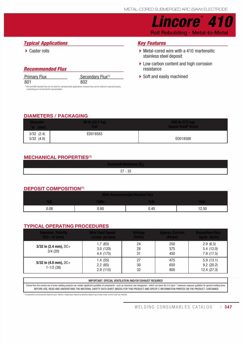
7/18/2019 c110 - Lincoln Electric Consumables 2014
http://slidepdf.com/reader/full/c110-lincoln-electric-consumables-2014 347/511W E L D I N G C O N S U M A B L E S C A TA L O G ı 347
Lincore ®
410METAL-CORED SUBMERGED ARC (SAW) ELECTRODE
Typical Applications
Caster rolls
Roll Rebuilding - Metal-to-Metal
DIAMETERS / PACKAGINGDiameter 50 lb (22.7 kg)
Coil600 lb (272 kg)
Speed-Feed® Drumin (mm)
3/32
5/32
(2.4)
(4.0)
ED018583
ED018588
Recommended Flux
Primary Flux801
Secondary Flux(1)
802
MECHANICAL PROPERTIES(1)
Rockwell Hardness (RC)
27 - 32
DEPOSIT COMPOSITION(1)
With Recommended Neutral Flux
%C %Mn %Si %Cr
0.08 0.80 0.40 12.50
(1) Composition and properties depend upon dilution. Single layer deposit properties depend upon base metal and/or build-up material.
TYPICAL OPERATING PROCEDURES
Diameter, PolarityESO - in (mm)
Wire Feed Speed Voltage(Volts)
Approx. Current(Amps)
Deposition Ratem/min (in/min) kg/hr (lb/hr)
3/32 in (2.4 mm), DC+
3/4 (20)
1.7
3.0
4.4
(65)
(120)
(175)
24
28
31
250
375
450
2.9
5.4
7.9
(6.5)
(12.0)
(17.5)
5/32 in (4.0 mm), DC+
1-1/2 (38)
1.4
2.2
2.9
(55)
(85)
(115)
27
30
32
475
650
800
5.9
9.2
12.4
(13.1)
(20.2)
(27.3)
IMPORTANT: SPECIAL VENTILATION AND/OR EXHAUST REQUIRED
Fumes from the normal use of some welding products can contain significant quantities of components - such as chromium and manganese - which can lower the 5.0 mg/m 3 maximum exposure guideline for general welding fume.
BEFORE USE, READ AND UNDERSTAND THE MATERIAL SAFETY DATA SHEET (MSDS) FOR THIS PRODUCT AND SPECIFIC INFORMATION PRINTED ON THE PRODUCT CONTAINER.
(1) 802 and 860 standard flux are not sized for semiautomatic applications; however, they can be ordered in special sizing by
contacting your Lincoln Electric representative.
Metal-cored wire with a 410 martensiticstainless steel deposit
Low carbon content and high corrosionresistance
Soft and easily machined
Key Features
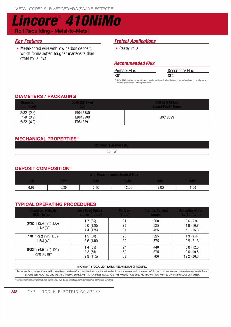
7/18/2019 c110 - Lincoln Electric Consumables 2014
http://slidepdf.com/reader/full/c110-lincoln-electric-consumables-2014 348/511348 ı T H E L I N C O L N E L E C T R I C C O M P A N Y
Lincore ®
410NiMo METAL-CORED SUBMERGED ARC (SAW) ELECTRODE
Typical Applications
Caster rolls
Roll Rebuilding - Metal-to-Metal
DIAMETERS / PACKAGING
Diameter 50 lb (22.7 kg)Coil
600 lb (272 kg)Speed-Feed® Drumin (mm)
3/321/8
5/32
(2.4)(3.2)
(4.0)
ED018589ED018590
EDS18591
ED018593
Recommended Flux
Primary Flux801
Secondary Flux(1)
802
MECHANICAL PROPERTIES(1)
Rockwell Hardness (RC)
32 - 40
DEPOSIT COMPOSITION(1)
With Recommended Neutral Flux
%C %Mn %Si %Cr %Ni %Mo
0.05 0.80 0.50 13.00 2.00 1.00
(1) Composition and properties depend upon dilution. Single layer deposit properties depend upon base metal and/or build-up material.
TYPICAL OPERATING PROCEDURES
Diameter, PolarityESO - in (mm)
Wire Feed Speed Voltage(Volts)
Approx. Current(Amps)
Deposition Ratem/min (in/min) kg/hr (lb/hr)
3/32 in (2.4 mm), DC+1-1/2 (38)
1.7
3.0
4.4
(65)
(120)
(175)
24
28
31
250
325
425
2.6
4.9
7.1
(5.8)
(10.7)
(15.6)
1/8 in (3.2 mm), DC+
1-5/8 (40)
1.5
3.6
(60)
(140)
26
30
325
575
4.3
9.9
(9.4)
(21.8)
5/32 in (4.0 mm), DC+
1-5/8 (40 mm)
1.4
2.2
2.9
(55)
(85)
(115)
27
30
32
440
575
700
5.8
9.0
12.2
(12.8)
(19.8)
(26.8)
IMPORTANT: SPECIAL VENTILATION AND/OR EXHAUST REQUIRED
Fumes from the normal use of some welding products can contain significant quantities of components - such as chromium and manganese - which can lower the 5.0 mg/m 3 maximum exposure guideline for general welding fume.
BEFORE USE, READ AND UNDERSTAND THE MATERIAL SAFETY DATA SHEET (MSDS) FOR THIS PRODUCT AND SPECIFIC INFORMATION PRINTED ON THE PRODUCT CONTAINER.
(1) 802 and 860 standard flux are not sized for semiautomatic applications; however, they can be ordered in special sizing by
contacting your Lincoln Electric representative.
Metal-cored wire with low carbon deposit,which forms softer, tougher martensite thanother roll alloys
Key Features
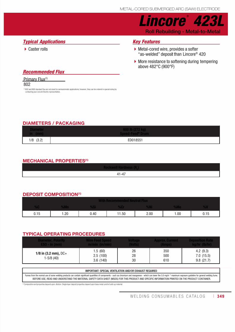
7/18/2019 c110 - Lincoln Electric Consumables 2014
http://slidepdf.com/reader/full/c110-lincoln-electric-consumables-2014 349/511W E L D I N G C O N S U M A B L E S C A TA L O G ı 349
METAL-CORED SUBMERGED ARC (SAW) ELECTRODE
Lincore ®
423L
Typical Applications
Caster rolls
Roll Rebuilding - Metal-to-Metal
DIAMETERS / PACKAGING
Diameter 600 lb (272 kg)Speed-Feed® Drumin (mm)
1/8 (3.2) ED018551
Recommended Flux
Primary Flux(1)
802
MECHANICAL PROPERTIES(1)
Rockwell Hardness (RC
)
41-47
DEPOSIT COMPOSITION(1)
With Recommended Neutral Flux
%C %Mn %Si %Cr %Ni %Mo %V
0.15 1.20 0.40 11.50 2.00 1.00 0.15
(1) Composition and properties depend upon dilution. Single layer deposit properties depend upon base metal and/or build-up material.
TYPICAL OPERATING PROCEDURES
Diameter, PolarityESO - in (mm)
Wire Feed Speed Voltage(Volts)
Approx. Current(Amps)
Deposition Ratem/min (in/min) kg/hr (lb/hr)
1/8 in (3.2 mm), DC+
1-5/8 (40)
1.5
2.5
3.6
(60)
(100)
(140)
26
28
30
350
500
610
4.2
7.0
9.8
(9.3)
(15.5)
(21.7)
IMPORTANT: SPECIAL VENTILATION AND/OR EXHAUST REQUIRED
Fumes from the normal use of some welding products can contain significant quantities of components - such as chromium and manganese - which can lower the 5.0 mg/m 3 maximum exposure guideline for general welding fume.
BEFORE USE, READ AND UNDERSTAND THE MATERIAL SAFETY DATA SHEET (MSDS) FOR THIS PRODUCT AND SPECIFIC INFORMATION PRINTED ON THE PRODUCT CONTAINER.
(1) 802 and 860 standard flux are not sized for semiautomatic applications; however, they can be ordered in special sizing by
contacting your Lincoln Electric representative.
Metal-cored wire, provides a softer“as-welded” deposit than Lincore® 420
More resistance to softening during temperingabove 482°C (900°F)
Key Features
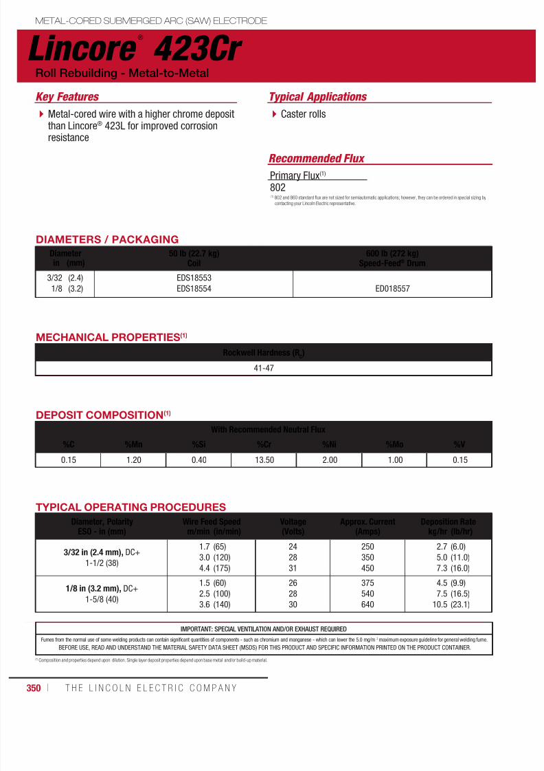
7/18/2019 c110 - Lincoln Electric Consumables 2014
http://slidepdf.com/reader/full/c110-lincoln-electric-consumables-2014 350/511350 ı T H E L I N C O L N E L E C T R I C C O M P A N Y
Lincore ®
423Cr METAL-CORED SUBMERGED ARC (SAW) ELECTRODE
Typical Applications
Caster rolls
Recommended Flux
Roll Rebuilding - Metal-to-Metal
DIAMETERS / PACKAGING
Diameter 50 lb (22.7 kg)
Coil
600 lb (272 kg)
Speed-Feed® Drumin (mm)3/32
1/8
(2.4)
(3.2)
EDS18553
EDS18554 ED018557
Primary Flux(1)
802
MECHANICAL PROPERTIES(1)
Rockwell Hardness (RC)
41-47
DEPOSIT COMPOSITION(1)
With Recommended Neutral Flux
%C %Mn %Si %Cr %Ni %Mo %V
0.15 1.20 0.40 13.50 2.00 1.00 0.15
(1) Composition and properties depend upon dilution. Single layer deposit properties depend upon base metal and/or build-up material.
TYPICAL OPERATING PROCEDURES
Diameter, PolarityESO - in (mm)
Wire Feed Speed Voltage(Volts)
Approx. Current(Amps)
Deposition Ratem/min (in/min) kg/hr (lb/hr)
3/32 in (2.4 mm), DC+
1-1/2 (38)
1.7
3.0
4.4
(65)
(120)
(175)
24
28
31
250
350
450
2.7
5.0
7.3
(6.0)
(11.0)
(16.0)
1/8 in (3.2 mm), DC+
1-5/8 (40)
1.5
2.5
3.6
(60)
(100)
(140)
26
28
30
375
540
640
4.5
7.5
10.5
(9.9)
(16.5)
(23.1)
IMPORTANT: SPECIAL VENTILATION AND/OR EXHAUST REQUIRED
Fumes from the normal use of some welding products can contain significant quantities of components - such as chromium and manganese - which can lower the 5.0 mg/m 3 maximum exposure guideline for general welding fume.
BEFORE USE, READ AND UNDERSTAND THE MATERIAL SAFETY DATA SHEET (MSDS) FOR THIS PRODUCT AND SPECIFIC INFORMATION PRINTED ON THE PRODUCT CONTAINER.
(1) 802 and 860 standard flux are not sized for semiautomatic applications; however, they can be ordered in special sizing by
contacting your Lincoln Electric representative.
Metal-cored wire with a higher chrome depositthan Lincore® 423L for improved corrosionresistance
Key Features
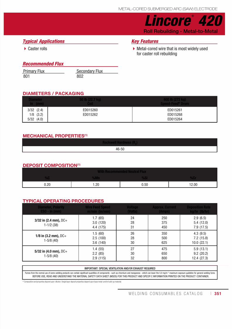
7/18/2019 c110 - Lincoln Electric Consumables 2014
http://slidepdf.com/reader/full/c110-lincoln-electric-consumables-2014 351/511W E L D I N G C O N S U M A B L E S C A TA L O G ı 351
Lincore ®
420METAL-CORED SUBMERGED ARC (SAW) ELECTRODE
Typical Applications
Caster rolls
Roll Rebuilding - Metal-to-Metal
DIAMETERS / PACKAGING
Diameter 50 lb (22.7 kg)Coil
600 lb (272 kg)Speed-Feed® Drumin (mm)
3/32
1/8
5/32
(2.4)
(3.2)
(4.0)
ED015260
ED015262
ED015261
ED015268
ED015264
Recommended Flux
Primary Flux801
Secondary Flux802
MECHANICAL PROPERTIES(1)
Rockwell Hardness (RC)
46-50
IMPORTANT: SPECIAL VENTILATION AND/OR EXHAUST REQUIRED
Fumes from the normal use of some welding products can contain significant quantities of components - such as chromium and manganese - which can lower the 5.0 mg/m 3 maximum exposure guideline for general welding fume.
BEFORE USE, READ AND UNDERSTAND THE MATERIAL SAFETY DATA SHEET (MSDS) FOR THIS PRODUCT AND SPECIFIC INFORMATION PRINTED ON THE PRODUCT CONTAINER.
DEPOSIT COMPOSITION(1)
With Recommended Neutral Flux
%C %Mn %Si %Cr
0.20 1.20 0.50 12.00
(1) Composition and properties depend upon dilution. Single layer deposit properties depend upon base metal and/or build-up material.
TYPICAL OPERATING PROCEDURES
Diameter, PolarityESO - in (mm)
Wire Feed Speed Voltage(Volts)
Approx. Current(Amps)
Deposition Ratem/min (in/min) kg/hr (lb/hr)
3/32 in (2.4 mm), DC+
1-1/2 (38)
1.7
3.0
4.4
(65)
(120)
(175)
24
28
31
250
375
450
2.9
5.4
7.9
(6.5)
(12.0)
(17.5)
1/8 in (3.2 mm), DC+
1-5/8 (40)
1.5
2.5
3.6
(60)
(100)
(140)
26
28
30
350
500
625
4.3
7.2
10.0
(9.5)
(15.8)
(22.1)
5/32 in (4.0 mm), DC+
1-5/8 (40)
1.4
2.2
2.9
(55)
(85)
(115)
27
30
32
475
650
800
5.9
9.2
12.4
(13.1)
(20.2)
(27.3)
Metal-cored wire that is most widely usedfor caster roll rebuilding
Key Features
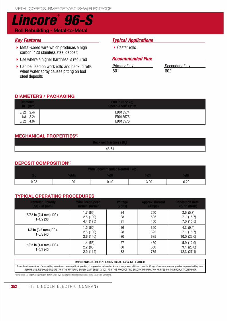
7/18/2019 c110 - Lincoln Electric Consumables 2014
http://slidepdf.com/reader/full/c110-lincoln-electric-consumables-2014 352/511352 ı T H E L I N C O L N E L E C T R I C C O M P A N Y
IMPORTANT: SPECIAL VENTILATION AND/OR EXHAUST REQUIRED
Fumes from the normal use of some welding products can contain significant quantities of components - such as chromium and manganese - which can lower the 5.0 mg/m 3 maximum exposure guideline for general welding fume.
BEFORE USE, READ AND UNDERSTAND THE MATERIAL SAFETY DATA SHEET (MSDS) FOR THIS PRODUCT AND SPECIFIC INFORMATION PRINTED ON THE PRODUCT CONTAINER.
Lincore ®
96-S
Typical Applications
Caster rolls
Roll Rebuilding - Metal-to-Metal
DIAMETERS / PACKAGING
Diameter 600 lb (272 kg)Speed-Feed® Drumin (mm)
3/32
1/8
5/32
(2.4)
(3.2)
(4.0)
ED018574
ED018575
ED018576
Recommended Flux
Primary Flux801
Secondary Flux802
MECHANICAL PROPERTIES(1)
Rockwell Hardness (RC)
48-54
DEPOSIT COMPOSITION(1)
With Recommended Neutral Flux
%C %Mn %Si %Cr %Ni
0.23 1.20 0.40 13.00 0.20
(1) Composition and properties depend upon dilution. Single layer deposit properties depend upon base metal and/or build-up material.
TYPICAL OPERATING PROCEDURES
Diameter, PolarityESO - in (mm)
Wire Feed Speed Voltage(Volts)
Approx. Current(Amps)
Deposition Ratem/min (in/min) kg/hr (lb/hr)
3/32 in (2.4 mm), DC+
1-1/2 (38)
1.7
2.5
4.4
(65)
(100)
(175)
24
28
31
250
525
450
2.6
7.1
7.0
(5.7)
(15.7)
(15.5)
1/8 in (3.2 mm), DC+
1-5/8 (40)
1.5
2.5
3.6
(60)
(100)
(140)
26
28
30
360
525
635
4.3
7.1
10.0
(9.4)
(15.7)
(22.0)
5/32 in (4.0 mm), DC+
1-5/8 (40)
1.4
2.2
2.9
(55)
(85)
(115)
27
30
32
450
650
775
5.9
9.1
12.3
(12.9)
(20.0)
(27.1)
METAL-CORED SUBMERGED ARC (SAW) ELECTRODE
Metal-cored wire which produces a highcarbon, 420 stainless steel deposit
Use where a higher hardness is required
Can be used on work rolls and backup rollswhen water spray causes pitting on toolsteel deposits
Key Features
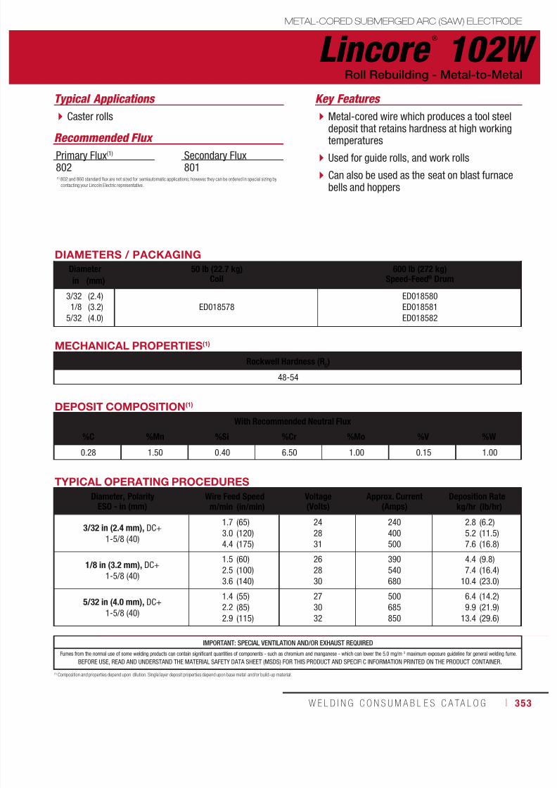
7/18/2019 c110 - Lincoln Electric Consumables 2014
http://slidepdf.com/reader/full/c110-lincoln-electric-consumables-2014 353/511W E L D I N G C O N S U M A B L E S C A TA L O G ı 353
Lincore ®
102WMETAL-CORED SUBMERGED ARC (SAW) ELECTRODE
Typical Applications
Caster rolls
Roll Rebuilding - Metal-to-Metal
DIAMETERS / PACKAGING
Diameter 50 lb (22.7 kg)Coil 600 lb (272 kg)Speed-Feed® Drumin (mm)
3/32
1/8
5/32
(2.4)
(3.2)
(4.0)
ED018578
ED018580
ED018581
ED018582
Recommended Flux
Primary Flux(1)
802Secondary Flux801
MECHANICAL PROPERTIES(1)
Rockwell Hardness (RC)
48-54
IMPORTANT: SPECIAL VENTILATION AND/OR EXHAUST REQUIRED
Fumes from the normal use of some welding products can contain significant quantities of components - such as chromium and manganese - which can lower the 5.0 mg/m 3 maximum exposure guideline for general welding fume.
BEFORE USE, READ AND UNDERSTAND THE MATERIAL SAFETY DATA SHEET (MSDS) FOR THIS PRODUCT AND SPECIFIC INFORMATION PRINTED ON THE PRODUCT CONTAINER.
DEPOSIT COMPOSITION(1)
With Recommended Neutral Flux
%C %Mn %Si %Cr %Mo %V %W
0.28 1.50 0.40 6.50 1.00 0.15 1.00
(1) Composition and properties depend upon dilution. Single layer deposit properties depend upon base metal and/or build-up material.
TYPICAL OPERATING PROCEDURES
Diameter, PolarityESO - in (mm)
Wire Feed Speed Voltage(Volts)
Approx. Current(Amps)
Deposition Ratem/min (in/min) kg/hr (lb/hr)
3/32 in (2.4 mm), DC+
1-5/8 (40)
1.7
3.0
4.4
(65)
(120)
(175)
24
28
31
240
400
500
2.8
5.2
7.6
(6.2)
(11.5)
(16.8)
1/8 in (3.2 mm), DC+
1-5/8 (40)
1.5
2.5
3.6
(60)
(100)
(140)
26
28
30
390
540
680
4.4
7.4
10.4
(9.8)
(16.4)
(23.0)
5/32 in (4.0 mm), DC+
1-5/8 (40)
1.4
2.2
2.9
(55)
(85)
(115)
27
30
32
500
685
850
6.4
9.9
13.4
(14.2)
(21.9)
(29.6)
(1) 802 and 860 standard flux are not sized for semiautomatic applications; however, they can be ordered in special sizing by
contacting your Lincoln Electric representative.
Metal-cored wire which produces a tool steeldeposit that retains hardness at high workingtemperatures
Used for guide rolls, and work rolls
Can also be used as the seat on blast furnacebells and hoppers
Key Features

7/18/2019 c110 - Lincoln Electric Consumables 2014
http://slidepdf.com/reader/full/c110-lincoln-electric-consumables-2014 354/511354 ı T H E L I N C O L N E L E C T R I C C O M P A N Y
IMPORTANT: SPECIAL VENTILATION AND/OR EXHAUST REQUIRED
Fumes from the normal use of some welding products can contain significant quantities of components - such as chromium and manganese - which can lower the 5.0 mg/m 3 maximum exposure guideline for general welding fume.
BEFORE USE, READ AND UNDERSTAND THE MATERIAL SAFETY DATA SHEET (MSDS) FOR THIS PRODUCT AND SPECIFIC INFORMATION PRINTED ON THE PRODUCT CONTAINER.
Lincore ®
102HC METAL-CORED SUBMERGED ARC (SAW) ELECTRODE
Typical Applications
Caster rolls
Roll Rebuilding - Metal-to-Metal
DIAMETERS / PACKAGING
Diameter 50 lb (22.7 kg)Coil
600 lb (272 kg)Speed-Feed® Drumin (mm)
3/32
1/8
(2.4)
(3.2) ED026085
ED026086
ED026087
Recommended Flux
Primary Flux(1)
802Secondary Flux801
MECHANICAL PROPERTIES(1)
Rockwell Hardness (RC)
54 - 60
DEPOSIT COMPOSITION(1)
With Recommended Neutral Flux
%C %Mn %Si %Cr %Mo %V %W
0.40 2.10 1.60 6.70 1.60 0.20 1.30
(1) Composition and properties depend upon dilution. Single layer deposit properties depend upon base metal and/or build-up material.
TYPICAL OPERATING PROCEDURES
Diameter, PolarityESO - in (mm)
Wire Feed Speed Voltage(Volts)
Approx. Current(Amps)
Deposition Ratem/min (in/min) kg/hr (lb/hr)
3/32 in (2.4 mm), DC+
1-1/2 (38)
1.7
3.0
4.4
(65)
(120)
(175)
24
28
31
240
400
500
2.8
5.2
7.6
(6.2)
(11.5)
(16.8)
1/8 in (3.2 mm), DC+
1-5/8 (40)
1.5
2.5
3.6
(60)
(100)
(140)
26
28
30
390
540
680
4.4
7.4
10.4
(9.8)
(16.4)
(23.0)
(1) 802 and 860 standard flux are not sized for semiautomatic applications; however, they can be ordered in special sizing by
contacting your Lincoln Electric representative.
Metal-cored wire with a higher carbon contentthan Lincore® 102W
Will give a higher hardness tool steel deposit
Deposit is “hot” [above 204°C (400°F)]machinable, for easy sizing after welding
Key Features
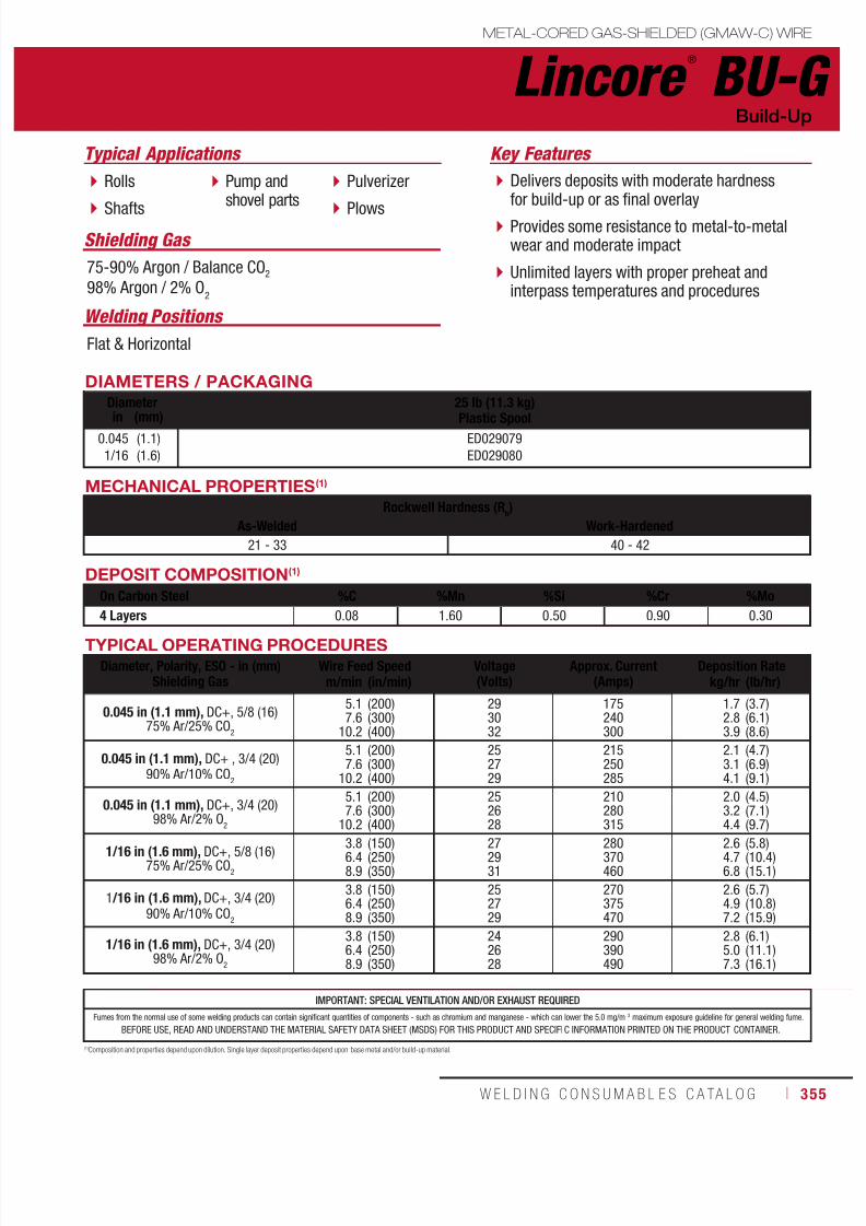
7/18/2019 c110 - Lincoln Electric Consumables 2014
http://slidepdf.com/reader/full/c110-lincoln-electric-consumables-2014 355/511W E L D I N G C O N S U M A B L E S C A TA L O G ı 355
Lincore ®
BU-GMETAL-CORED GAS-SHIELDED (GMAW-C) WIRE
Welding Positions
Typical Applications
Flat & Horizontal
Rolls
Shafts
Pump andshovel parts
Pulverizer
Plows
Build-Up
DIAMETERS / PACKAGING
Diameter 25 lb (11.3 kg)
Plastic Spoolin (mm)0.045
1/16
(1.1)
(1.6)
ED029079
ED029080
Shielding Gas
75-90% Argon / Balance CO2
98% Argon / 2% O2
MECHANICAL PROPERTIES(1)
Rockwell Hardness (Rb)
As-Welded Work-Hardened
21 - 33 40 - 42
DEPOSIT COMPOSITION(1)
On Carbon Steel %C %Mn %Si %Cr %Mo
4 Layers 0.08 1.60 0.50 0.90 0.30
(1)Composition and properties depend upon dilution. Single layer deposit properties depend upon base metal and/or build-up material.
TYPICAL OPERATING PROCEDURES
Diameter, Polarity, ESO - in (mm)Shielding Gas
Wire Feed Speed Voltage(Volts)
Approx. Current(Amps)
Deposition Ratem/min (in/min) kg/hr (lb/hr)
0.045 in (1.1 mm), DC+, 5/8 (16)75% Ar/25% CO
2
5.17.6
10.2
(200)(300)(400)
293032
175240300
1.72.83.9
(3.7)(6.1)(8.6)
0.045 in (1.1 mm), DC+ , 3/4 (20)90% Ar/10% CO
2
5.17.6
10.2
(200)(300)(400)
252729
215250285
2.13.14.1
(4.7)(6.9)(9.1)
0.045 in (1.1 mm), DC+, 3/4 (20)98% Ar/2% O
2
5.17.6
10.2
(200)(300)(400)
252628
210280315
2.03.24.4
(4.5)(7.1)(9.7)
1/16 in (1.6 mm), DC+, 5/8 (16)75% Ar/25% CO
2
3.86.48.9
(150)(250)(350)
272931
280370460
2.64.76.8
(5.8)(10.4)(15.1)
1 /16 in (1.6 mm), DC+, 3/4 (20)90% Ar/10% CO
2
3.86.48.9
(150)(250)(350)
252729
270375470
2.64.97.2
(5.7)(10.8)(15.9)
1/16 in (1.6 mm), DC+, 3/4 (20)98% Ar/2% O
2
3.86.48.9
(150)(250)(350)
242628
290390490
2.85.07.3
(6.1)(11.1)(16.1)
IMPORTANT: SPECIAL VENTILATION AND/OR EXHAUST REQUIRED
Fumes from the normal use of some welding products can contain significant quantities of components - such as chromium and manganese - which can lower the 5.0 mg/m 3 maximum exposure guideline for general welding fume.
BEFORE USE, READ AND UNDERSTAND THE MATERIAL SAFETY DATA SHEET (MSDS) FOR THIS PRODUCT AND SPECIFIC INFORMATION PRINTED ON THE PRODUCT CONTAINER.
Delivers deposits with moderate hardnessfor build-up or as final overlay
Provides some resistance to metal-to-metalwear and moderate impact
Unlimited layers with proper preheat andinterpass temperatures and procedures
Key Features
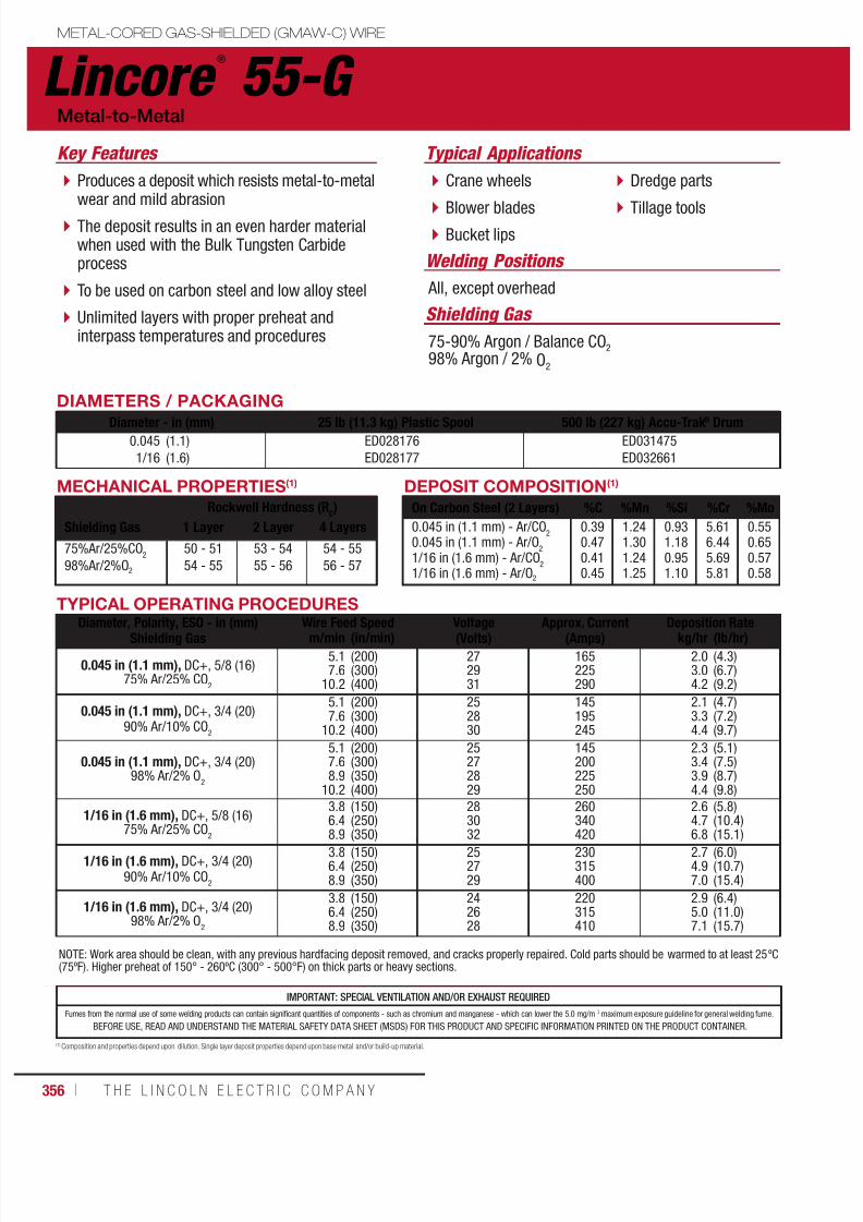
7/18/2019 c110 - Lincoln Electric Consumables 2014
http://slidepdf.com/reader/full/c110-lincoln-electric-consumables-2014 356/511356 ı T H E L I N C O L N E L E C T R I C C O M P A N Y
DIAMETERS / PACKAGING
Diameter - in (mm) 25 lb (11.3 kg) Plastic Spool 500 lb (227 kg) Accu-Trak® Drum0.045
1/16
(1.1)
(1.6)
ED028176
ED028177
ED031475
ED032661
Lincore ®
55-G METAL-CORED GAS-SHIELDED (GMAW-C) WIRE
Typical Applications
All, except overhead
Crane wheels
Blower blades Bucket lips
Dredge parts
Tillage tools
Metal-to-Metal
MECHANICAL PROPERTIES(1)
Rockwell Hardness (RC)
Shielding Gas 1 Layer 2 Layer 4 Layers
75%Ar/25%CO2
98%Ar/2%O2
50 - 51
54 - 55
53 - 54
55 - 56
54 - 55
56 - 57
75-90% Argon / Balance CO2
98% Argon / 2% O2
DEPOSIT COMPOSITION(1)
On Carbon Steel (2 Layers) %C %Mn %Si %Cr %Mo
0.045 in (1.1 mm) - Ar/CO2
0.045 in (1.1 mm) - Ar/O2
1/16 in (1.6 mm) - Ar/CO2
1/16 in (1.6 mm) - Ar/O2
0.390.470.410.45
1.241.301.241.25
0.931.180.951.10
5.616.445.695.81
0.550.650.570.58
(1) Composition and properties depend upon dilution. Single layer deposit properties depend upon base metal and/or build-up material.
IMPORTANT: SPECIAL VENTILATION AND/OR EXHAUST REQUIRED
Fumes from the normal use of some welding products can contain significant quantities of components - such as chromium and manganese - which can lower the 5.0 mg/m 3 maximum exposure guideline for general welding fume.
BEFORE USE, READ AND UNDERSTAND THE MATERIAL SAFETY DATA SHEET (MSDS) FOR THIS PRODUCT AND SPECIFIC INFORMATION PRINTED ON THE PRODUCT CONTAINER.
TYPICAL OPERATING PROCEDURES
Diameter, Polarity, ESO - in (mm)Shielding Gas Wire Feed Speed Voltage(Volts) Approx. Current(Amps) Deposition Ratem/min (in/min) kg/hr (lb/hr)
0.045 in (1.1 mm), DC+, 5/8 (16)75% Ar/25% CO
2
5.17.6
10.2
(200)(300)(400)
272931
165225290
2.03.04.2
(4.3)(6.7)(9.2)
0.045 in (1.1 mm), DC+, 3/4 (20)90% Ar/10% CO
2
5.17.6
10.2
(200)(300)(400)
252830
145195245
2.13.34.4
(4.7)(7.2)(9.7)
0.045 in (1.1 mm), DC+, 3/4 (20)98% Ar/2% O
2
5.17.68.9
10.2
(200)(300)(350)(400)
25272829
145200225250
2.33.43.94.4
(5.1)(7.5)(8.7)(9.8)
1/16 in (1.6 mm), DC+, 5/8 (16)
75% Ar/25% CO2
3.86.4
8.9
(150)(250)
(350)
2830
32
260340
420
2.64.7
6.8
(5.8)(10.4)
(15.1)
1/16 in (1.6 mm), DC+, 3/4 (20)90% Ar/10% CO
2
3.86.48.9
(150)(250)(350)
252729
230315400
2.74.97.0
(6.0)(10.7)(15.4)
1/16 in (1.6 mm), DC+, 3/4 (20)98% Ar/2% O
2
3.86.48.9
(150)(250)(350)
242628
220315410
2.95.07.1
(6.4)(11.0)(15.7)
NOTE: Work area should be clean, with any previous hardfacing deposit removed, and cracks properly repaired. Cold parts should be warmed to at least 25ºC(75ºF). Higher preheat of 150° - 260ºC (300° - 500°F) on thick parts or heavy sections.
Welding Positions
Shielding Gas
Produces a deposit which resists metal-to-metalwear and mild abrasion
The deposit results in an even harder materialwhen used with the Bulk Tungsten Carbideprocess
To be used on carbon steel and low alloy steel
Unlimited layers with proper preheat andinterpass temperatures and procedures
Key Features
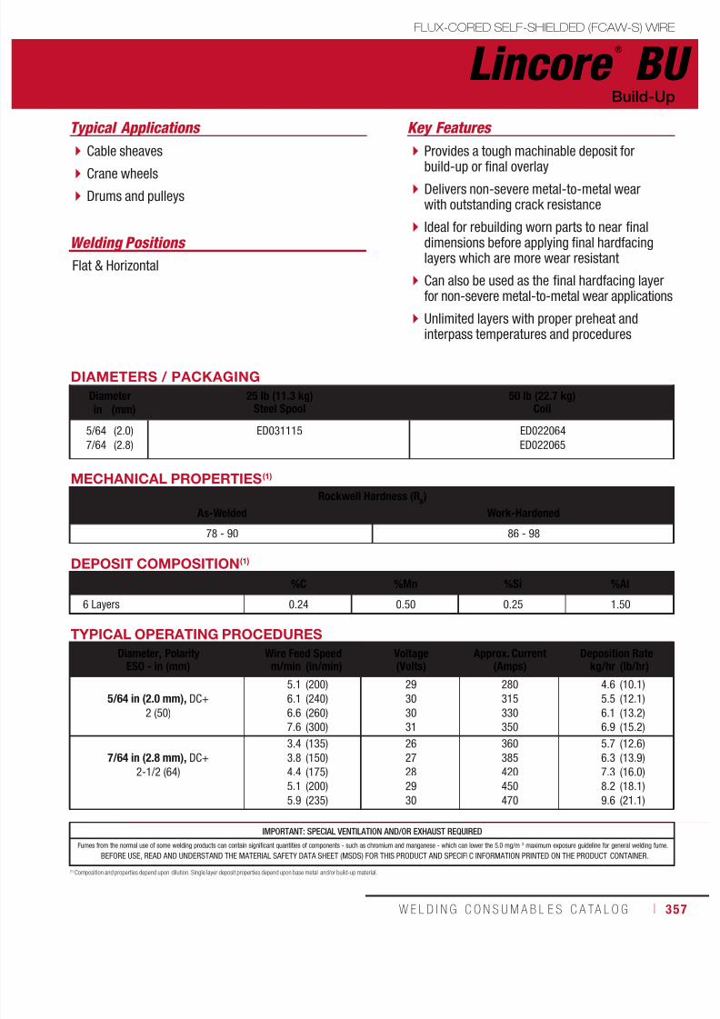
7/18/2019 c110 - Lincoln Electric Consumables 2014
http://slidepdf.com/reader/full/c110-lincoln-electric-consumables-2014 357/511W E L D I N G C O N S U M A B L E S C A TA L O G ı 357
TYPICAL OPERATING PROCEDURES
Diameter, PolarityESO - in (mm)
Wire Feed Speed Voltage(Volts)
Approx. Current(Amps)
Deposition Ratem/min (in/min) kg/hr (lb/hr)
5/64 in (2.0 mm), DC+2 (50)
5.1
6.16.6
7.6
(200)
(240)(260)
(300)
29
3030
31
280
315330
350
4.6
5.56.1
6.9
(10.1)
(12.1)(13.2)
(15.2)
7/64 in (2.8 mm), DC+
2-1/2 (64)
3.4
3.8
4.4
5.1
5.9
(135)
(150)
(175)
(200)
(235)
26
27
28
29
30
360
385
420
450
470
5.7
6.3
7.3
8.2
9.6
(12.6)
(13.9)
(16.0)
(18.1)
(21.1)
Lincore ®
BU
Welding Positions
Typical Applications
Flat & Horizontal
Cable sheaves
Crane wheels Drums and pulleys
Provides a tough machinable deposit forbuild-up or final overlay
Delivers non-severe metal-to-metal wearwith outstanding crack resistance
Ideal for rebuilding worn parts to near finaldimensions before applying final hardfacinglayers which are more wear resistant
Can also be used as the final hardfacing layerfor non-severe metal-to-metal wear applications
Unlimited layers with proper preheat andinterpass temperatures and procedures
Build-Up
Key Features
DIAMETERS / PACKAGING
Diameter 25 lb (11.3 kg)Steel Spool
50 lb (22.7 kg)Coilin (mm)
5/64
7/64
(2.0)
(2.8)
ED031115 ED022064
ED022065
DEPOSIT COMPOSITION(1)
%C %Mn %Si %Al
6 Layers 0.24 0.50 0.25 1.50
(1) Composition and properties depend upon dilution. Single layer deposit properties depend upon base metal and/or build-up material.
MECHANICAL PROPERTIES(1)
Rockwell Hardness (RB)
As-Welded Work-Hardened
78 - 90 86 - 98
IMPORTANT: SPECIAL VENTILATION AND/OR EXHAUST REQUIRED
Fumes from the normal use of some welding products can contain significant quantities of components - such as chromium and manganese - which can lower the 5.0 mg/m 3 maximum exposure guideline for general welding fume.
BEFORE USE, READ AND UNDERSTAND THE MATERIAL SAFETY DATA SHEET (MSDS) FOR THIS PRODUCT AND SPECIFIC INFORMATION PRINTED ON THE PRODUCT CONTAINER.
FLUX-CORED SELF-SHIELDED (FCAW-S) WIRE

7/18/2019 c110 - Lincoln Electric Consumables 2014
http://slidepdf.com/reader/full/c110-lincoln-electric-consumables-2014 358/511358 ı T H E L I N C O L N E L E C T R I C C O M P A N Y
Lincore ®
33 FLUX-CORED SELF-SHIELDED (FCAW-S) WIRE
Welding Positions
Typical Applications
Flat & Horizontal
Tractor rolls andidlers
Shovel parts
Mine car wheels
Mill and crusherhammers
Dredge pumps
Delivers tough machinable deposits for build-up or finaloverlay intended for metal-to-metal wear
Use for build-up of steel mill parts such as rougher couplings
Build-up deposit on carbon steel and low alloy steelbase metals
It is ideal for rebuilding worn parts to near final dimensionsbefore applying final hardfacing layers which are morewear resistant
Unlimited layers with proper preheat and interpasstemperatures and procedures
Build-Up
Key Features
DIAMETERS / PACKAGINGDiameter 14 lb (6.4 kg) Coil
56 lb (25.4 kg) Master Carton25 lb (11.3 kg)
Steel Spool50 lb (22.7 kg)
Coilin (mm)
0.0451/16 5/647/64
(1.2)(1.6)(2.0)(2.8)
ED011237
ED031116ED031117ED031118 ED011238
ED011240
MECHANICAL PROPERTIES(1)
Rockwell Hardness (RC)
No. of Layers As-Welded Work-Hardened Flame-Hardened / Water Quenched123
14-3026-3225-34
28-3432-3635-38
–38-42
–
IMPORTANT: SPECIAL VENTILATION AND/OR EXHAUST REQUIRED
Fumes from the normal use of some welding products can contain significant quantities of components - such as chromium and manganese - which can lower the 5.0 mg/m 3 maximum exposure guideline for general welding fume.
BEFORE USE, READ AND UNDERSTAND THE MATERIAL SAFETY DATA SHEET (MSDS) FOR THIS PRODUCT AND SPECIFIC INFORMATION PRINTED ON THE PRODUCT CONTAINER.
TYPICAL OPERATING PROCEDURES
Diameter, PolarityESO - in (mm)
Wire Feed Speed Voltage(Volts)
Approx. Current(Amps)
Deposition Ratem/min (in/min) kg/hr (lb/hr)
0.045 in (1.1 mm), DC+1-3/4 (45)
5.18.9
12.7
(200)(350)(500)
252831
80130150
1.52.73.9
(3.3)(6.0)(8.7)
1/16 in (1.6 mm), DC+1-3/4 (45)
3.86.48.9
(150)(250)(350)
262932
125180225
2.13.55.0
(4.6)(7.8)(11.1)
5/64 in (2.0 mm), DC+2 (50)
3.25.16.4
(125)(200)(250)
232729
200290325
3.14.96.1
(6.9)(10.8)(21.1)
7/64 in (2.8 mm), DC+2-1/2 (64)
3.44.46.0
(135)(175)(235)
262830
360420470
5.77.39.6
(12.6)(16.0)(21.1)
DEPOSIT COMPOSITION(1)
%C %Mn %Si %Al %Cr %S %P3 Layers (0.045 in & 1/16 in)3 Layers (5/64 in & 7/64 in)
0.11-0.180.13-0.15
1.8-2.12.1-2.3
0.50-0.750.45-0.60
1.6-1.91.45-1.70
1.2-1.41.1-1.4
0.002-0.0050.002-0.005
0.004-0.0120.004-0.008
(1) Composition and properties depend upon dilution. Single layer deposit properties depend upon base metal and/or build-up material.
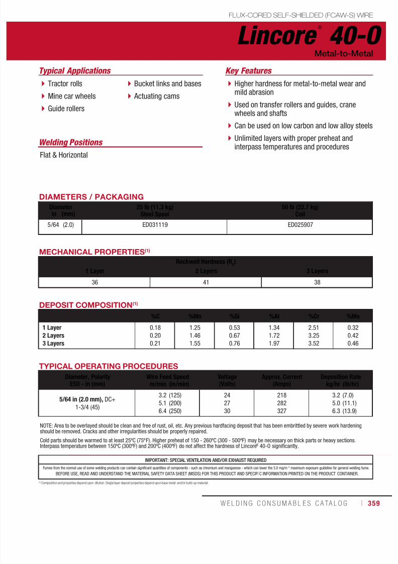
7/18/2019 c110 - Lincoln Electric Consumables 2014
http://slidepdf.com/reader/full/c110-lincoln-electric-consumables-2014 359/511W E L D I N G C O N S U M A B L E S C A TA L O G ı 359
Lincore ®
40-OFLUX-CORED SELF-SHIELDED (FCAW-S) WIRE
Welding Positions
Typical Applications
Flat & Horizontal
Tractor rolls
Mine car wheels Guide rollers
Bucket links and bases
Actuating cams
Higher hardness for metal-to-metal wear andmild abrasion
Used on transfer rollers and guides, cranewheels and shafts
Can be used on low carbon and low alloy steels
Unlimited layers with proper preheat andinterpass temperatures and procedures
Metal-to-Metal
Key Features
DIAMETERS / PACKAGING
Diameter 25 lb (11.3 kg)Steel Spool
50 lb (22.7 kg)Coilin (mm)
5/64 (2.0) ED031119 ED025907
DEPOSIT COMPOSITION(1)
%C %Mn %Si %Al %Cr %Mo
1 Layer2 Layers3 Layers
0.18
0.20
0.21
1.25
1.46
1.55
0.53
0.67
0.76
1.34
1.72
1.97
2.51
3.25
3.52
0.32
0.42
0.46
(1) Composition and properties depend upon dilution. Single layer deposit properties depend upon base metal and/or build-up material.
MECHANICAL PROPERTIES(1)
Rockwell Hardness (RC)
1 Layer 2 Layers 3 Layers
36 41 38
IMPORTANT: SPECIAL VENTILATION AND/OR EXHAUST REQUIRED
Fumes from the normal use of some welding products can contain significant quantities of components - such as chromium and manganese - which can lower the 5.0 mg/m 3 maximum exposure guideline for general welding fume.
BEFORE USE, READ AND UNDERSTAND THE MATERIAL SAFETY DATA SHEET (MSDS) FOR THIS PRODUCT AND SPECIFIC INFORMATION PRINTED ON THE PRODUCT CONTAINER.
NOTE: Area to be overlayed should be clean and free of rust, oil, etc. Any previous hardfacing deposit that has been embrittled by severe work hardeningshould be removed. Cracks and other irregularities should be properly repaired.
Cold parts should be warmed to at least 25ºC (75ºF). Higher preheat of 150 - 260ºC (300 - 500ºF) may be necessary on thick parts or heavy sections.Interpass temperature between 150ºC (300ºF) and 200ºC (400ºF) do not affect the hardness of Lincore® 40-O significantly.
TYPICAL OPERATING PROCEDURES
Diameter, Polarity
ESO - in (mm)
Wire Feed Speed Voltage
(Volts)
Approx. Current
(Amps)
Deposition Rate
m/min (in/min) kg/hr (lb/hr)
5/64 in (2.0 mm), DC+
1-3/4 (45)
3.2
5.1
6.4
(125)
(200)
(250)
24
27
30
218
282
327
3.2
5.0
6.3
(7.0)
(11.1)
(13.9)

7/18/2019 c110 - Lincoln Electric Consumables 2014
http://slidepdf.com/reader/full/c110-lincoln-electric-consumables-2014 360/511360 ı T H E L I N C O L N E L E C T R I C C O M P A N Y
IMPORTANT: SPECIAL VENTILATION AND/OR EXHAUST REQUIRED
Fumes from the normal use of some welding products can contain significant quantities of components - such as chromium and manganese - which can lower the 5.0 mg/m 3 maximum exposure guideline for general welding fume.
BEFORE USE, READ AND UNDERSTAND THE MATERIAL SAFETY DATA SHEET (MSDS) FOR THIS PRODUCT AND SPECIFIC INFORMATION PRINTED ON THE PRODUCT CONTAINER.
Lincore ®
55 FLUX-CORED SELF-SHIELDED (FCAW-S) WIRE
Welding Positions
Typical Applications
Flat & Horizontal
Crane wheels
Blower blades Rail ends
Skip guides
Cams and transfertables
Delivers a deposit which resists metal-to-metalrolling or sliding wear as well as mild abrasion
To be used on carbon steel, low alloy steeland manganese steel
Unlimited layers with proper preheat andinterpass temperatures and procedures
Metal-to-Metal
Key Features
DIAMETERS / PACKAGINGDiameter 14 lb (6.4 kg) Coil
56 lb (25.4 kg) Master Carton25 lb (11.3 kg)
Steel Spool50 lb (22.7 kg)
Coilin (mm)
0.045
1/16
5/647/64
(1.2)
(1.6)
(2.0)(2.8)
ED011277
ED031120
ED031121
ED031122 ED011278ED011280
MECHANICAL PROPERTIES(1)
Rockwell Hardness (RC)
No. of Layers As-Welded Work-Hardened 180°C (350°F) Interpass Temp Flame-Hardened / Water Quenched
12
50 - 59
50 - 60
53 - 62
56 - 62
50 - 55
55 - 59
–
52 - 54
DEPOSIT COMPOSITION(1)
%C %Mn %Si %Al %Cr %Mo %S %P
0.045 in & 1/16 in
5/64 in & 7/64 in
0.45
0.45
1.3
1.4
0.53
0.60
1.4
1.4
5.3
5.3
0.80
0.80
0.004
0.004
0.010
0.010
(1) Composition and properties depend upon dilution. Single layer deposit properties depend upon base metal and/or build-up material.
TYPICAL OPERATING PROCEDURES
Diameter, PolarityESO - in (mm)
Wire Feed Speed Voltage(Volts)
Approx. Current(Amps)
Deposition Ratem/min (in/min) kg/hr (lb/hr)
0.045 in (1.1 mm), DC+
1-3/4 (45)
5.1
8.9
12.7
(200)
(350)
(500)
25
28
31
85
125
165
1.6
3.0
4.3
(3.6)
(6.6)
(9.4)
1/16 in (1.6 mm), DC+
1-3/4 (45)
3.8
6.4
8.9
(150)
(250)
(350)
26
29
32
125
195
245
2.2
3.8
5.5
(4.8)
(8.4)
(12.1)
5/64 in (2.0 mm), DC+
1-3/4 (45)
3.2
5.1
6.4
(125)
(200)
(250)
24
27
30
190
295
330
3.2
5.0
6.2
(7.0)
(11.0)
(13.7)
7/64 in (2.8 mm), DC+
2-1/2 (64)
2.3
3.2
4.4
(90)
(125)
(175)
25
27
30
280
350
420
3.8
5.2
7.3
(8.4)
(11.5)
(16.0)
NOTE: Area to be overlayed should be clean and free of rust, oil, etc. Any previous hardfacing deposit that has been embrittled by severe work hardeningshould be removed. Cracks and other irregularities should be properly repaired.
Cold parts should be warmed to at least 25ºC (75ºF). Higher preheat of 150 - 260ºC (300 - 500ºF) may be necessary on thick parts or heavy sections.Interpass temperature between 150ºC (300ºF) and 200ºC (400ºF) do not affect the hardness of Lincore® 55 significantly.

7/18/2019 c110 - Lincoln Electric Consumables 2014
http://slidepdf.com/reader/full/c110-lincoln-electric-consumables-2014 361/511W E L D I N G C O N S U M A B L E S C A TA L O G ı 361
Lincore ®
T & D
Welding Positions
Typical Applications
Flat & Horizontal
Punch dies
Shear blades
Delivers a deposit similar to H12 tool steel
For build-up of tool steel dies and edges, orapplying wear resistance surface on carbonor low alloy steels
To be used on carbon steel, low alloy steelor tool steel
Metal-to-Metal
Key Features
DIAMETERS / PACKAGING
Diameter 25 lb (11.3 kg)Steel Spool
in (mm)1/16 (1.6) ED031134
MECHANICAL PROPERTIES(1)
Rockwell Hardness (RC)
As-Welded Tempered at 540°C (1000°F)
48 - 55 55 - 65
DEPOSIT COMPOSITION(1)
%C %Mn %Si %Al %Cr %Mo %W
6 Layers Open Arc6 Layers w/ 802 Flux
0.65
0.50
1.5
1.9
0.8
1.0
1.8
1.0
7.0
7.0
1.4
1.4
1.6
1.6
(1) Composition and properties depend upon dilution. Single layer deposit properties depend upon base metal and/or build-up material.
TYPICAL OPERATING PROCEDURES
Diameter, PolarityESO - in (mm)
Wire Feed Speed Voltage(Volts)
Approx. Current(Amps)
Deposition Ratem/min (in/min) kg/hr (lb/hr)
1/16 in (1.6 mm), DC+
1-1/4 (32)
3.85.1
6.4
7.6
8.9
(150)(200)
(250)
(300)
(350)
2223
24
25
26
170210
250
270
300
2.43.6
4.1
4.9
5.4
(5.4)(7.9)
(8.9)
(10.8)
(12.0)
NOTE: Minimum preheat and interpass temperatures of 315°C (600°F) are essential for crack-free welding on mild steel or low alloy steel. For crack-freewelding on tool steel parts, preheat of 538°C (1000°F) or higher may be necessary. After welding, very slow cooling to 121°C (250°F) is usually required.This can be followed by post-weld heat treating at 538° - 593°C (1000° - 1100°F) to develop maximum hardness.
IMPORTANT: SPECIAL VENTILATION AND/OR EXHAUST REQUIRED
Fumes from the normal use of some welding products can contain significant quantities of components - such as chromium and manganese - which can lower the 5.0 mg/m 3 maximum exposure guideline for general welding fume.
BEFORE USE, READ AND UNDERSTAND THE MATERIAL SAFETY DATA SHEET (MSDS) FOR THIS PRODUCT AND SPECIFIC INFORMATION PRINTED ON THE PRODUCT CONTAINER.
FLUX-CORED SELF-SHIELDED (FCAW-S) WIRE
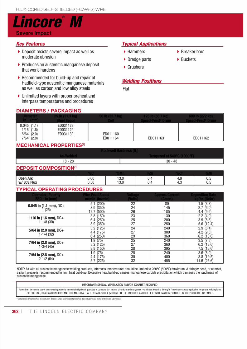
7/18/2019 c110 - Lincoln Electric Consumables 2014
http://slidepdf.com/reader/full/c110-lincoln-electric-consumables-2014 362/511362 ı T H E L I N C O L N E L E C T R I C C O M P A N Y
DEPOSIT COMPOSITION(1)
%C %Mn %Si %Cr %Ni
Open Arcw/ 803 Flux 0.600.50 13.013.0 0.40.4 4.94.3 0.50.5
IMPORTANT: SPECIAL VENTILATION AND/OR EXHAUST REQUIRED
Fumes from the normal use of some welding products can contain significant quantities of components - such as chromium and manganese - which can lower the 5.0 mg/m 3 maximum exposure guideline for general welding fume.
BEFORE USE, READ AND UNDERSTAND THE MATERIAL SAFETY DATA SHEET (MSDS) FOR THIS PRODUCT AND SPECIFIC INFORMATION PRINTED ON THE PRODUCT CONTAINER.
Lincore ®
M FLUX-CORED SELF-SHIELDED (FCAW-S) WIRE
Welding Positions
Typical Applications
Flat
Hammers
Dredge parts Crushers
Breaker bars
Buckets
Deposit resists severe impact as well asmoderate abrasion
Produces an austenitic manganese depositthat work-hardens
Recommended for build-up and repair ofHadfield-type austenitic manganese materialsas well as carbon and low alloy steels
Unlimited layers with proper preheat andinterpass temperatures and procedures
Severe Impact
Key Features
DIAMETERS / PACKAGINGDiameter 25 lb (11.3 kg)
Steel Spool
50 lb (22.7 kg)
Coil
125 lb (56.7 kg)
Speed-Feed® Drum
600 lb (272 kg)
Speed-Feed® Drumin (mm)0.0451/165/647/64
(1.1)(1.6)(2.0)(2.8)
ED031128ED031129ED031130 ED011160
ED011164 ED011163 ED011162
(1) Composition and properties depend upon dilution. Single layer deposit properties depend upon base metal and/or build-up material.
MECHANICAL PROPERTIES(1)
Rockwell Hardness (RC)
As-Welded Tempered at 540°C (1000°F)18 - 28 30 - 48
TYPICAL OPERATING PROCEDURESDiameter, Polarity
ESO - in (mm)Wire Feed Speed Voltage
(Volts)Approx. Current
(Amps)Deposition Rate
m/min (in/min) kg/hr (lb/hr)
0.045 in (1.1 mm), DC+1 (25)
5.18.9
12.7
(200)(350)(500)
222426
80145185
1.52.74.4
(3.3)(6.0)(9.6)
1/16 in (1.6 mm), DC+1-1/8 (30)
3.86.48.9
(150)(250)(350)
232527
130200250
2.23.95.6
(4.9)(8.6)(12.4)
5/64 in (2.0 mm), DC+1-1/4 (32)
3.24.46.4
(125)(175)(250)
242729
240300360
2.94.26.2
(6.4)(9.3)(13.6)
7/64 in (2.8 mm), DC+1-3/4 (45)
1.93.23.8
(75)(125)(150)
252728
240360395
3.56.27.5
(7.8)(13.6)(16.6)
7/64 in (2.8 mm), DC+2-1/2 (64)
1.94.45.7
(75)(175)(225)
253032
240400455
3.68.8
11.6
(8.0)(19.5)(25.6)
NOTE: As with all austenitic manganese welding products, interpass temperatures should be limited to 260°C (500°F) maximum. A stringer bead, or at most,a slight weave is recommended to limit heat build-up. Excessive heat build-up causes manganese carbide precipitation which damages the toughness ofaustenitic manganese.

7/18/2019 c110 - Lincoln Electric Consumables 2014
http://slidepdf.com/reader/full/c110-lincoln-electric-consumables-2014 363/511W E L D I N G C O N S U M A B L E S C A TA L O G ı 363
Lincore ®
15CrMnFLUX-CORED SELF-SHIELDED (FCAW-S) WIRE
Welding Positions
Typical Applications
Flat & Horizontal
Spreader cones
Crusher hammers Austenitic manganese parts
Provides an austenitic manganese depositwhich exhibits very good crack resistance
Work-hardens for overlay or joining austeniticmanganese steel to itself or to carbon steel
Can be used as a build-up layer beforecapping with abrasion resistant alloys
Can be used in open arc mode for joining austeniticmanganese steel to carbon steel, low alloy steel,austenitic manganese steel, or stainless steel
Unlimited layers with proper preheat andinterpass temperatures and procedures
Severe Impact
Key Features
DIAMETERS / PACKAGINGDiameter 25 lb (11.3 kg)
Steel Spool50 lb (22.7 kg)
Coil125 lb (56.7 kg)
Speed-Feed® Drumin (mm)5/647/64
(2.0)(2.8)
ED031126 ED022060ED022061 ED022068
DEPOSIT COMPOSITION(1)
%C %Mn %Si %CrSix Layers Open ArcSix Layers w/ 801 Flux
0.40.4
15.015.0
0.250.6
16.016.0
(1) Composition and properties depend upon dilution. Single layer deposit properties depend upon base metal and/or build-up material.
MECHANICAL PROPERTIES(1)
Rockwell Hardness (RC)
As-Welded Work-Hardened18 - 22 40-50
IMPORTANT: SPECIAL VENTILATION AND/OR EXHAUST REQUIRED
Fumes from the normal use of some welding products can contain significant quantities of components - such as chromium and manganese - which can lower the 5.0 mg/m 3 maximum exposure guideline for general welding fume.
BEFORE USE, READ AND UNDERSTAND THE MATERIAL SAFETY DATA SHEET (MSDS) FOR THIS PRODUCT AND SPECIFIC INFORMATION PRINTED ON THE PRODUCT CONTAINER.
TYPICAL OPERATING PROCEDURESDiameter, Polarity
ESO - in (mm)Wire Feed Speed Voltage
(Volts)Approx. Current
(Amps)Deposition Rate
m/min (in/min) kg/hr (lb/hr)
5/64 in (2.0 mm), DC+1-1/4 (32)
3.25.16.48.9
(125)(200)(250)(350)
26293032
210280320380
3.35.36.89.7
(7.3)(11.7)(15.1)(21.3)
7/64 in (2.8 mm), DC+1-3/4 (45)
1.93.23.84.4
(75)(125)(150)(175)
26282930
250320350380
2.55.16.67.5
(5.5)(11.3)(14.6)(16.4)
7/64 in (2.8 mm), DC+2-1/2 (64)
3.85.15.76.4
(150)(200)(225)(250)
30333435
320390410425
6.78.79.8
11.4
(14.9)(19.2)(21.7)(25.1)
NOTE: As with all austenitic manganese welding products, interpass temperatures should be limited to 260°C (500°F) maximum. A stringer bead, or at most,a slight weave is recommended to limit heat build-up. Excessive heat build-up causes manganese carbide precipitation which damages the toughness ofaustenitic manganese.

7/18/2019 c110 - Lincoln Electric Consumables 2014
http://slidepdf.com/reader/full/c110-lincoln-electric-consumables-2014 364/511364 ı T H E L I N C O L N E L E C T R I C C O M P A N Y
IMPORTANT: SPECIAL VENTILATION AND/OR EXHAUST REQUIRED
Fumes from the normal use of some welding products can contain significant quantities of components - such as chromium and manganese - which can lower the 5.0 mg/m 3 maximum exposure guideline for general welding fume.
BEFORE USE, READ AND UNDERSTAND THE MATERIAL SAFETY DATA SHEET (MSDS) FOR THIS PRODUCT AND SPECIFIC INFORMATION PRINTED ON THE PRODUCT CONTAINER.
Lincore ®
FROG MANG ®
FLUX-CORED SELF-SHIELDED (FCAW-S) WIRE
Typical Applications
Manganese crossing diamonds
Manganese railroad frogs
Designed for repair of manganese frogs andmanganese crossing diamonds in the railroadindustry
High alloy austenitic manganese deposit
Unlimited layers with proper preheat andinterpass temperatures and procedures
Severe Impact
Key Features
DIAMETERS / PACKAGING
Diameter 9 lb (4 kg) Plastic Spool36 lb (16.3 kg) Master Carton
25 lb (11.3 kg)Steel Spoolin (mm)
1/16
5/64
(1.6)
(2.0) ED034485
ED026106
ED026105
MECHANICAL PROPERTIES(1)
Rockwell Hardness (RC)
As-Welded Work-Hardened
20 - 30 40 - 50
DEPOSIT COMPOSITION(1)
%C %Mn %Si %Cr
6 Layers 1.07 25.5 0.17 4.59
(1) Composition and properties depend upon dilution. Single layer deposit properties depend upon base metal and/or build-up material.
TYPICAL OPERATING PROCEDURES
Diameter, PolarityESO - in (mm)
Wire Feed Speed Voltage(Volts)
Approx. Current(Amps)
Deposition Ratem/min (in/min) kg/hr (lb/hr)
1/16 in (1.6 mm), DC+
1 (25)
5.1
6.4
8.3
(200)
(250)
(325)
27
29
32
220
250
300
3.0
4.0
5.3
(6.7)
(8.7)
(11.6)
5/64 in (2.0 mm), DC+
2 (50)
3.85.1
6.4
(150)(200)
(250)
2729
31
240290
340
3.44.9
6.4
(7.4)(10.7)
(14.0)
NOTE: Remove all damaged and foreign material by the air-carbon arc gouging process and grinding. Make sure all defective metal is removed. In the eventhairline cracks remain at flangeway depth, use a 1/8 in diameter E308 stainless product, such as Blue Max® or Red Baron® 308L AC-DC to tie up these cracksand avoid hot cracking during the buildup process. Use only light amounts and do not build-up with E308 stainless. It is for use in emergency situations whereno other alternative is available to repair flangeway cracks. As with all austenitic manganese welding products, interpass temperatures should be limited to260°C (500°F) maximum. A stringer bead, or at most, a slight weave is recommended to limit heat build-up. Excessive heat build-up causes manganesecarbide precipitation which damages the toughness of austenitic manganese.

7/18/2019 c110 - Lincoln Electric Consumables 2014
http://slidepdf.com/reader/full/c110-lincoln-electric-consumables-2014 365/511W E L D I N G C O N S U M A B L E S C A TA L O G ı 365
Lincore ®
50
Welding Positions
Typical Applications
Flat & Horizontal
Crusher rolls
Dredge cutter teeth Ore chute baffles
Muller plows and tires
Coal mining cuttingteeth
Delivers an abrasion resistant deposit, evenunder conditions of moderate impact
Larger wire diameter sizes may be used forthe submerged arc process
Can be used on low carbon, medium carbon,low alloy, manganese and stainless steels
Limited to 4 layers
Abrasion & Impact
Key Features
DIAMETERS / PACKAGINGDiameter - in (mm) 25 lb (11.3 kg) Steel Spool 50 lb (22.7 kg) Coil 125 lb (56.7 kg) Speed-Feed® Drum
0.0451/16
5/647/64
(1.1)(1.6)
(2.0)(2.8)
ED031123ED031124
ED031125
ED020829
ED017825ED011275 ED011274
MECHANICAL PROPERTIES(1)
Rockwell Hardness (RC)
1 Layer 2 Layers 3 Layers
On Mild SteelOn 0.50% Carbon SteelOn Austenitic Mn Steelwith 801 Flux
34-37
41-43
-
38-43
44-48
47-50
43-45
47-52
48-52
50-53
48-50
48-56
DEPOSIT COMPOSITION(1)
%C %Mn %Si %Al %Cr %MoOpen Arc 0.045 in & 1/16 in 5/64 in & 7/64 in
2.42.0
1.30.9
1.01.0
0.60.6
11.49.2
–0.5
Submerged Arc5/64 in & 7/64 in
w/ 801 Flux w/ 803 Flux w/ 860 Flux
2.52.52.5
1.11.82.0
1.31.21.7
0.40.20.2
10.111.111.0
0.50.50.5
(1) Composition and properties depend upon dilution. Single layer deposit properties depend upon base metal and/or build-up material.
TYPICAL OPERATING PROCEDURES
Diameter, PolarityESO - in (mm)
Wire Feed Speed Voltage(Volts)
Approx. Current(Amps)
Deposition Ratem/min (in/min) kg/hr (lb/hr)
0.045 in (1.1mm), DC+1 (25)
5.110.215.2
(200)(400)(600)
19-2123-2527-29
120190250
1.93.95.8
(4.2)(8.5)(12.8)
1/16 in (1.6 mm), DC+1 (25)
3.88.4
11.4
(150)(350)(450)
22-2429-3132-34
175325365
2.76.27.9
(5.9)(13.6)(17.5)
5/64 in (2.0 mm), DC+1-1/4 (32)
3.25.16.4
(125)(200)(250)
273133
210325380
3.45.46.8
(7.4)(11.9)(14.9)
7/64 in (2.8 mm), DC+1-1/4 (32)
2.02.53.3
(80)(100)(130)
262729
315375450
3.94.96.4
(8.6)(10.7)(14.0)
7/64 in (2.8 mm), DC+2-1/2 (64)
2.53.34.4
(100)(130)(175)
272931
315370450
4.96.48.6
(10.7)(14.0)(19.0)
With Recommended Neutral Fluxes
7/64 in (2.8 mm), DC+1-1/4 (32)
2.53.04.4
(100)(120)(175)
293033
400450540
5.26.29.1
(11.4)(13.7)(20.0)
IMPORTANT: SPECIAL VENTILATION AND/OR EXHAUST REQUIRED
Fumes from the normal use of some welding products can contain significant quantities of components - such as chromium and manganese - which can lower the 5.0 mg/m 3 maximum exposure guideline for general welding fume.
BEFORE USE, READ AND UNDERSTAND THE MATERIAL SAFETY DATA SHEET (MSDS) FOR THIS PRODUCT AND SPECIFIC INFORMATION PRINTED ON THE PRODUCT CONTAINER.
FLUX-CORED SELF-SHIELDED (FCAW-S) WIRE

7/18/2019 c110 - Lincoln Electric Consumables 2014
http://slidepdf.com/reader/full/c110-lincoln-electric-consumables-2014 366/511366 ı T H E L I N C O L N E L E C T R I C C O M P A N Y
IMPORTANT: SPECIAL VENTILATION AND/OR EXHAUST REQUIRED
Fumes from the normal use of some welding products can contain significant quantities of components - such as chromium and manganese - which can lower the 5.0 mg/m 3 maximum exposure guideline for general welding fume.
BEFORE USE, READ AND UNDERSTAND THE MATERIAL SAFETY DATA SHEET (MSDS) FOR THIS PRODUCT AND SPECIFIC INFORMATION PRINTED ON THE PRODUCT CONTAINER.
Lincore ®
60-O FLUX-CORED SELF-SHIELDED (FCAW-S) WIRE
Welding Positions
Typical Applications
Flat & Horizontal
Bucket lips
Crusher hammers Ore chutes
Dozer blades
Ripper teeth
Deposits feature higher alloy levels than toresist both abrasion and moderate impact
Can be used at temperatures up to 704°C(1300°F)
To be used on carbon, low alloy, manganese,stainless steels and cast iron
Deposit is limited to two layers
Severe Abrasion
Key Features
DIAMETERS / PACKAGING
Diameter 25 lb (11.3 kg)Steel Spool
50 lb (22.7 kg)Coilin (mm)
0.0451/165/647/64
(1.1)(1.6)(2.0)(2.8)
ED031131ED031132ED031133 ED019887
ED019888
MECHANICAL PROPERTIES(1)
Rockwell Hardness (RC)
55-60
DEPOSIT COMPOSITION(1)
%C %Mn %Si %Al %Cr2 Layers Open Arc2 Layers w/ 803 Flux
4.24.8
1.64.1
1.31.2
0.60.2
25.425.8
(1) Composition and properties depend upon dilution. Single layer deposit properties depend upon base metal and/or build-up material.
TYPICAL OPERATING PROCEDURESDiameter, Polarity
ESO - in (mm)Wire Feed Speed Voltage
(Volts)Approx. Current
(Amps)Deposition Rate
m/min (in/min) kg/hr (lb/hr)0.045 in (1.1mm), DC+
1 (25)5.1
10.212.7
(200)(400)(500)
212527
125185210
1.93.74.7
(4.1)(8.2)(10.3)
1/16 in (1.6 mm), DC+7/8 (22)
5.17.6
11.4
(200)(300)(450)
283133
240300350
3.45.17.5
(7.6)(11.2)(16.6)
5/64 in (2.0 mm), DC+1-1/4 (32)
3.25.16.4
(125)(200)(250)
263032
250350400
3.45.46.9
(7.4)(12.0)(15.1)
7/64 in (2.8 mm), DC+1-1/8 (30)
1.93.24.4
(75)(125)(175)
273032
250340420
3.45.47.5
(7.4)(11.9)(16.5)
With Recommended Neutral Fluxes7/64 in (2.8 mm), DC+
1-1/8 (30)2.53.24.4
(100)(125)(175)
303234
295340420
4.45.47.5
(9.6)(11.9)(16.5)
NOTE: Deposit thickness limit is two layers unless high travel speed is used to obtain very closely spaced check cracks. Many layers can be used with hightravel speed and small bead sizes to ensure close-spaced check cracks. Lincore® 60-0 deposit cross cracks (commonly called cross-checking) on cooling.This is desirable, since cross-cracking of the deposit relieves cooling stresses and prevents spalling.
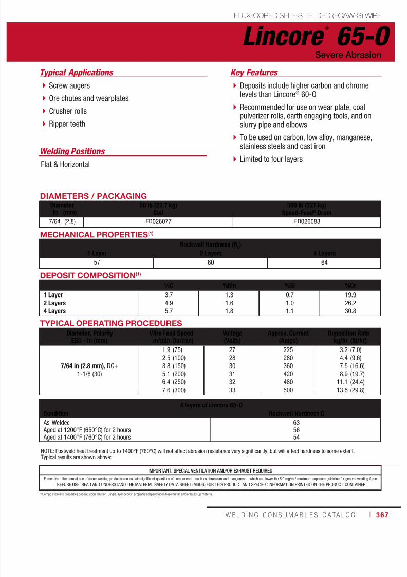
7/18/2019 c110 - Lincoln Electric Consumables 2014
http://slidepdf.com/reader/full/c110-lincoln-electric-consumables-2014 367/511W E L D I N G C O N S U M A B L E S C A TA L O G ı 367
DEPOSIT COMPOSITION(1)
%C %Mn %Si %Cr
1 Layer2 Layers4 Layers
3.74.9
5.7
1.31.6
1.8
0.71.0
1.1
19.926.2
30.8
Lincore ®
65-OFLUX-CORED SELF-SHIELDED (FCAW-S) WIRE
Welding Positions
Typical Applications
Flat & Horizontal
Screw augers
Ore chutes and wearplates Crusher rolls
Ripper teeth
Deposits include higher carbon and chromelevels than Lincore® 60-O
Recommended for use on wear plate, coalpulverizer rolls, earth engaging tools, and onslurry pipe and elbows
To be used on carbon, low alloy, manganese,stainless steels and cast iron
Limited to four layers
Severe Abrasion
Key Features
DIAMETERS / PACKAGINGDiameter 50 lb (22.7 kg)
Coil500 lb (227 kg)
Speed-Feed® Drumin (mm)
7/64 (2.8) ED026077 ED026083
MECHANICAL PROPERTIES(1)
Rockwell Hardness (RC)
1 Layer 2 Layers 4 Layers
57 60 64
(1) Composition and properties depend upon dilution. Single layer deposit properties depend upon base metal and/or build-up material.
TYPICAL OPERATING PROCEDURES
Diameter, PolarityESO - in (mm)
Wire Feed Speed Voltage(Volts)
Approx. Current(Amps)
Deposition Ratem/min (in/min) kg/hr (lb/hr)
7/64 in (2.8 mm), DC+
1-1/8 (30)
1.9
2.5
3.8
5.1
6.4
7.6
(75)
(100)
(150)
(200)
(250)
(300)
27
28
30
31
32
33
225
280
360
420
480
500
3.2
4.4
7.5
8.9
11.1
13.5
(7.0)
(9.6)
(16.6)
(19.7)
(24.4)
(29.8)
NOTE: Postweld heat treatment up to 1400°F (760°C) will not affect abrasion resistance very significantly, but will affect hardness to some extent.Typical results are shown above:
4 layers of Lincore 65-OCondition Rockwell Hardness C
As-Welded Aged at 1200°F (650°C) for 2 hours Aged at 1400°F (760°C) for 2 hours
635654
IMPORTANT: SPECIAL VENTILATION AND/OR EXHAUST REQUIRED
Fumes from the normal use of some welding products can contain significant quantities of components - such as chromium and manganese - which can lower the 5.0 mg/m 3 maximum exposure guideline for general welding fume.
BEFORE USE, READ AND UNDERSTAND THE MATERIAL SAFETY DATA SHEET (MSDS) FOR THIS PRODUCT AND SPECIFIC INFORMATION PRINTED ON THE PRODUCT CONTAINER.

7/18/2019 c110 - Lincoln Electric Consumables 2014
http://slidepdf.com/reader/full/c110-lincoln-electric-consumables-2014 368/511368 ı T H E L I N C O L N E L E C T R I C C O M P A N Y
Packaging
Lincolnweld ®
A-96-S SUBMERGED ARC (SAW) FLUX
Alloy Flux
Typical Applications
Use with Lincolnweld® L-60 mild steel wire forhardfacing
Modified Type 420 stainless deposit witha carbon content near the high side foras-welded hardness
Designed to produce a weld deposit with13% chromium, 0.23% carbon when properprocedures are followed
Key Features
NOTE: Deposit carbon, alloy content and hardness depend upon the ratio of flux melted to wire melted. High voltage promotes high carbon and alloycontents, while low voltage promotes lower carbon and alloy content.
60 lb (27.2 kg) Plastic Bag ED031860
Lincolnweld ®
H-535 ™
Typical Applications
Use with Lincolnweld® L-60 mild steel wire forhardfacing
Produces a deposit with good abrasionresistance, allows some machinability
Low carbon martensitic deposit
Hardness range is 24-45 Rockwell C (RC),
depending upon the actual weldingprocedure used
Alloy Flux
Key Features
NOTE: Deposit carbon, alloy content and hardness depend upon the ratio of flux melted to wire melted. High voltage promotes high carbon and alloycontents, while low voltage promotes lower carbon and alloy content.
Packaging
50 lb (22.7 kg) Paper Bag ED027865

7/18/2019 c110 - Lincoln Electric Consumables 2014
http://slidepdf.com/reader/full/c110-lincoln-electric-consumables-2014 369/511W E L D I N G C O N S U M A B L E S C A TA L O G ı 369
Lincolnweld ®
H-560 ™
SUBMERGED ARC (SAW) FLUX
Typical Applications
Use with Lincolnweld® L-60 mild steel wire forhardfacing
High alloy flux depositing primary carbidesin a martensitic matrix
Excellent material for severe abrasionapplications
Resistance to abrasion is 50 to 60 timesthat of plain carbon steel
EN 760 – S A Z 3 • Alloy Flux
Key Features
NOTE: Deposit carbon, alloy content and hardness depend upon the ratio of flux melted to wire melted. High voltage promotes high carbon and alloycontents, while low voltage promotes lower carbon and alloy content.
Packaging
Lincolnweld ®
801®
Typical Applications
Hardfacing
Use with Lincore® 20, 30-S, 35-S, 40-S, 42-S,4130, 8620, 410, 410NiMo, 420 and 96S
Provides smooth beads and excellent slagremoval
Fast-freezing
EN 760 – S A FB 1; EN 760 – S A FB 2 • Neutral Flux
Key Features
NOTE: Deposit carbon, alloy content and hardness depend upon the ratio of flux melted to wire melted. High voltage promotes high carbon and alloycontents, while low voltage promotes lower carbon and alloy content.
Packaging
100 lb (45.4 kg) Paper Bag ED010345
50 lb (22.7 kg) Paper Bag
550 lb (249 kg) Drum
3000 lb (1361 kg) Bulk Bag
ED019588
ED023403
EDS30786

7/18/2019 c110 - Lincoln Electric Consumables 2014
http://slidepdf.com/reader/full/c110-lincoln-electric-consumables-2014 370/511370 ı T H E L I N C O L N E L E C T R I C C O M P A N Y
Typical Applications
Hardfacing
Use with Lincore® 102W, 423L, 423Cr and 102HC
Excellent hot slag removal with wire containingniobium, vanadium or very high chrome levels
Neutral Flux • EN 760 – S A CS 1; EN 760 – S A CS 2
Key Features
Lincolnweld ®
802 ®
NOTE: Deposit carbon, alloy content and hardness depend upon the ratio of flux melted to wire melted. High voltage promotes high carbon and alloycontents, while low voltage promotes lower carbon and alloy content.
Packaging
Lincolnweld ®
803 ™
Typical Applications
Hardfacing with Lincore® 60-SSpecially designed for high speed weldingapplications, such as the resurfacing of coalcrusher rolls or blast furnace bells and hoppers
Neutral Flux
Key Features
NOTE: Deposit carbon, alloy content and hardness depend upon the ratio of flux melted to wire melted. High voltage promotes high carbon and alloycontents, while low voltage promotes lower carbon and alloy content.
Packaging
50 lb (22.7 kg) Paper Bag
450 lb (204 kg) Drum
2700 lb (1225 kg) Bulk Bag
ED032800
ED023365
EDS30787
50 lb (22.7 kg) Plastic Bag ED032796
SUBMERGED ARC (SAW) FLUX

7/18/2019 c110 - Lincoln Electric Consumables 2014
http://slidepdf.com/reader/full/c110-lincoln-electric-consumables-2014 371/511W E L D I N G C O N S U M A B L E S C A TA L O G ı 371
CONSUMABLES
AluminumMIG WireSuperGlaze® 4043 ........................................ 372SuperGlaze® 4047 ........................................ 373SuperGlaze® 5183 ........................................ 374SuperGlaze® 5356 ........................................ 375SuperGlaze® 5356 TM™ ................................ 376SuperGlaze® 5554 ........................................ 377SuperGlaze® 5556 ........................................ 378
TIG Cut LengthSuperGlaze® 4043 ........................................ 379SuperGlaze® 5356 ........................................ 380
Cast IronStick ElectrodeFerroweld™ ..................................................381
ALUMINUM& CAST IRON
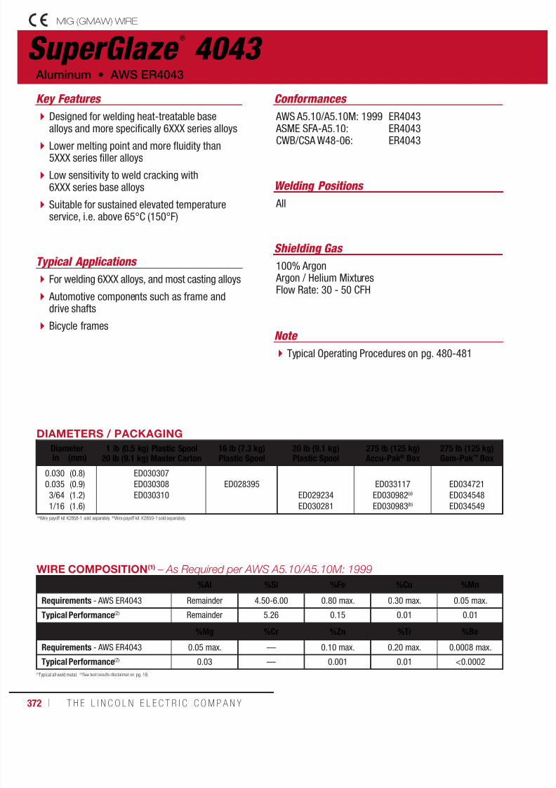
7/18/2019 c110 - Lincoln Electric Consumables 2014
http://slidepdf.com/reader/full/c110-lincoln-electric-consumables-2014 372/511372 ı T H E L I N C O L N E L E C T R I C C O M P A N Y
SuperGlaze ®
4043 MIG (GMAW) WIRE
Welding Positions
Typical Applications
All
For welding 6XXX alloys, and most casting alloys
Automotive components such as frame anddrive shafts
Bicycle frames
Designed for welding heat-treatable basealloys and more specifically 6XXX series alloys
Lower melting point and more fluidity than5XXX series filler alloys
Low sensitivity to weld cracking with6XXX series base alloys
Suitable for sustained elevated temperatureservice, i.e. above 65°C (150°F)
Conformances
Shielding Gas
100% Argon Argon / Helium MixturesFlow Rate: 30 - 50 CFH
Aluminum • AWS ER4043
Key Features
AWS A5.10/A5.10M: 1999 ASME SFA-A5.10:CWB/CSA W48-06:
ER4043ER4043ER4043
DIAMETERS / PACKAGING
Diameter 1 lb (0.5 kg) Plastic Spool20 lb (9.1 kg) Master Carton
16 lb (7.3 kg)Plastic Spool
20 lb (9.1 kg)Plastic Spool
275 lb (125 kg)Accu-Pak® Box
275 lb (125 kg)Gem-Pak™ Boxin (mm)
0.030
0.035
3/64
1/16
(0.8)
(0.9)
(1.2)
(1.6)
ED030307
ED030308
ED030310
ED028395
ED029234
ED030281
ED033117
ED030982(a)
ED030983(b)
ED034721
ED034548
ED034549(a)Wire payoff kit K2858-1 sold separately. (b)Wire payoff kit K2859-1 sold separately.
(1)Typical all weld metal. (2)See test results disclaimer on pg. 18.
WIRE COMPOSITION(1) – As Required per AWS A5.10/A5.10M: 1999
%Al %Si %Fe %Cu %Mn
Requirements - AWS ER4043 Remainder 4.50-6.00 0.80 max. 0.30 max. 0.05 max.
Typical Performance(2) Remainder 5.26 0.15 0.01 0.01
%Mg %Cr %Zn %Ti %Be
Requirements - AWS ER4043 0.05 max. — 0.10 max. 0.20 max. 0.0008 max.
Typical Performance(2) 0.03 — 0.001 0.01 <0.0002
Note
Typical Operating Procedures on pg. 480-481

7/18/2019 c110 - Lincoln Electric Consumables 2014
http://slidepdf.com/reader/full/c110-lincoln-electric-consumables-2014 373/511W E L D I N G C O N S U M A B L E S C A TA L O G ı 373
SuperGlaze ®
4047MIG (GMAW) WIRE
Welding Positions
Typical Applications
All
Automotive components
Heat exchangers
Body panels
Lower melting point and higher fluidity than4043 wires
Can be used as a substitute for 4043 wiresto increase silicon in the weld metal, minimizehot cracking and produce higher fillet weldshear strength
Conformances
Shielding Gas
100% Argon
Argon / Helium MixturesFlow Rate: 30 - 50 CFH
AWS ER4047 • Aluminum
Key Features
AWS A5.10/A5.10M: 1999
ASME SFA-A5.10
ER4047
ER4047
DIAMETERS / PACKAGING
Diameter 16 lb (7.3 kg) Plastic Spoolin (mm)
3/64
1/16
(1.2)
(1.6)
EDS28417
EDS28418
(1)Typical all weld metal. (2)See test results disclaimer on pg. 18.
WIRE COMPOSITION(1) – As Required per AWS A5.10/A5.10M: 1999
%Al %Si %Fe %Cu %Mn
Requirements - AWS ER4047 Remainder 11.00-13.00 0.80 max. 0.30 max. 0.15 max.
Typical Performance(2) As Reported per AWS Requirements
%Mg %Cr %Zn %Ti %Be
Requirements - AWS ER4047 0.10 max. — 0.20 max. — 0.0008 max.
Typical Performance(2) As Reported per AWS Requirements
Note
Typical Operating Procedures on pg. 480-481
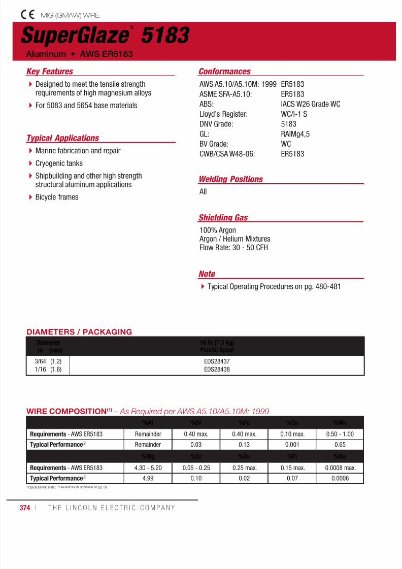
7/18/2019 c110 - Lincoln Electric Consumables 2014
http://slidepdf.com/reader/full/c110-lincoln-electric-consumables-2014 374/511374 ı T H E L I N C O L N E L E C T R I C C O M P A N Y
SuperGlaze ®
5183 MIG (GMAW) WIRE
Welding Positions
Typical Applications
All
Marine fabrication and repair
Cryogenic tanks
Shipbuilding and other high strengthstructural aluminum applications
Bicycle frames
Designed to meet the tensile strengthrequirements of high magnesium alloys
For 5083 and 5654 base materials
Conformances
Shielding Gas
100% Argon Argon / Helium MixturesFlow Rate: 30 - 50 CFH
Aluminum • AWS ER5183
Key Features
AWS A5.10/A5.10M: 1999
ASME SFA-A5.10: ABS:
Lloyd’s Register:
DNV Grade:
GL:
BV Grade:
CWB/CSA W48-06:
ER5183
ER5183IACS W26 Grade WC
WC/I-1 S
5183
RAIMg4,5
WC
ER5183
DIAMETERS / PACKAGING
Diameter 16 lb (7.3 kg)Plastic Spoolin (mm)
3/64
1/16
(1.2)
(1.6)
EDS28437
EDS28438
(1)Typical all weld metal. (2)See test results disclaimer on pg. 18.
WIRE COMPOSITION(1) – As Required per AWS A5.10/A5.10M: 1999
%Al %Si %Fe %Cu %Mn
Requirements - AWS ER5183 Remainder 0.40 max. 0.40 max. 0.10 max. 0.50 - 1.00
Typical Performance(2) Remainder 0.03 0.13 0.001 0.65
%Mg %Cr %Zn %Ti %Be
Requirements - AWS ER5183 4.30 - 5.20 0.05 - 0.25 0.25 max. 0.15 max. 0.0008 max.
Typical Performance(2) 4.99 0.10 0.02 0.07 0.0006
Note
Typical Operating Procedures on pg. 480-481
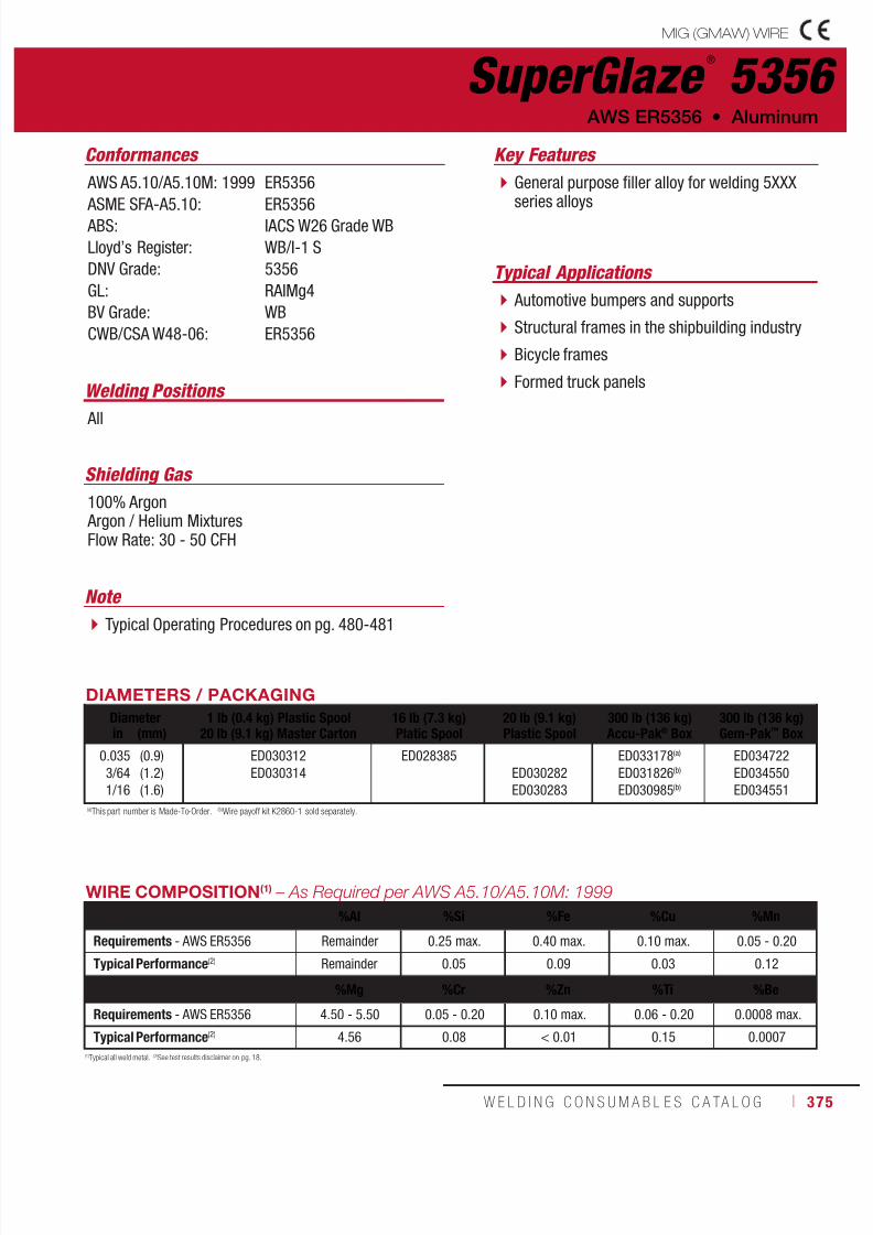
7/18/2019 c110 - Lincoln Electric Consumables 2014
http://slidepdf.com/reader/full/c110-lincoln-electric-consumables-2014 375/511W E L D I N G C O N S U M A B L E S C A TA L O G ı 375
SuperGlaze ®
5356MIG (GMAW) WIRE
Welding Positions
Typical Applications
All
Automotive bumpers and supports
Structural frames in the shipbuilding industry
Bicycle frames
Formed truck panels
General purpose filler alloy for welding 5XXXseries alloys
Conformances
Shielding Gas
100% Argon Argon / Helium MixturesFlow Rate: 30 - 50 CFH
AWS ER5356 • Aluminum
Key Features
AWS A5.10/A5.10M: 1999
ASME SFA-A5.10: ABS:
Lloyd’s Register:
DNV Grade:
GL:
BV Grade:
CWB/CSA W48-06:
ER5356
ER5356IACS W26 Grade WB
WB/I-1 S
5356
RAIMg4
WB
ER5356
DIAMETERS / PACKAGING
Diameter 1 lb (0.4 kg) Plastic Spool20 lb (9.1 kg) Master Carton
16 lb (7.3 kg)Platic Spool
20 lb (9.1 kg)Plastic Spool
300 lb (136 kg)Accu-Pak® Box
300 lb (136 kg)Gem-Pak™ Boxin (mm)
0.035
3/64
1/16
(0.9)
(1.2)
(1.6)
ED030312
ED030314
ED028385
ED030282
ED030283
ED033178(a)
ED031826(b)
ED030985(b)
ED034722
ED034550
ED034551(a)This part number is Made-To-Order. (b)Wire payoff kit K2860-1 sold separately.
(1)Typical all weld metal. (2)See test results disclaimer on pg. 18.
WIRE COMPOSITION(1) – As Required per AWS A5.10/A5.10M: 1999
%Al %Si %Fe %Cu %Mn
Requirements - AWS ER5356 Remainder 0.25 max. 0.40 max. 0.10 max. 0.05 - 0.20
Typical Performance(2) Remainder 0.05 0.09 0.03 0.12
%Mg %Cr %Zn %Ti %Be
Requirements - AWS ER5356 4.50 - 5.50 0.05 - 0.20 0.10 max. 0.06 - 0.20 0.0008 max.
Typical Performance(2) 4.56 0.08 < 0.01 0.15 0.0007
Note
Typical Operating Procedures on pg. 480-481

7/18/2019 c110 - Lincoln Electric Consumables 2014
http://slidepdf.com/reader/full/c110-lincoln-electric-consumables-2014 376/511376 ı T H E L I N C O L N E L E C T R I C C O M P A N Y
SuperGlaze ®
5356 TM ™
MIG (GMAW) WIRE
Welding Positions
Typical Applications
All
High speed groove welds on formed truckpanels
Multi-pass fillet and lap welds on 6XXX seriesbase materials
Robotic fillet welds on trailer tanks requiringminimal post-weld clean up
Unparalleled bead profile and appearancewhich are critical for groove and fillet weldson aluminum trailer beds.
SuperGlaze® 5356 TM™ has an engineeredchemical composition developed specificallyto outperform standard ER5356 electrodesand gives the operator unprecedented control.
Proprietary manufacturing processes giveSuperGlaze® 5356 TM™ the smoothest surfacefinish in the industry, making it ideal forautomatic applications on formed truck panels.
Conformances
Shielding Gas
100% Argon Argon / Helium MixturesFlow Rate: 30 - 50 CFH
Aluminum • AWS ER5356
Key Features
AWS A5.10/A5.10M: 1999 ASME SFA-A5.10:
CWB/CSA W48-06:
ER5356
ER5356ER5356
Note
Typical Operating Procedures on pg. 480-481
WIRE COMPOSITION – As required per AWS A5.10/A5.10M: 1999%Al %Si %Fe %Cu %Mn
Requirements - AWS ER5356 Remainder 0.25 max. 0.40 max. 0.10 max. 0.05 - 0.20
%Mg %Cr %Zn %Ti %Be
Requirements - AWS ER5356 4.50 - 5.50 0.05 - 0.20 0.10 max. 0.06 - 0.20 0.0008 max.
DIAMETERS / PACKAGINGDiameter 1 lb (0.4 kg) Plastic Spool
20 lb (9.1 kg) Master Carton16 lb (7.3 kg)Steel Spool
20 lb (9.1 kg)Plastic Spool
275 lb (125 kg)Gem-Pak™in. (mm)
0.035
3/64
1/16
(0.9)
(1.2)
(1.6)
ED034064
ED034065
ED034066
ED034067
ED034068
ED034069
—
ED034070
ED034071
ED034723
ED034724
ED034729
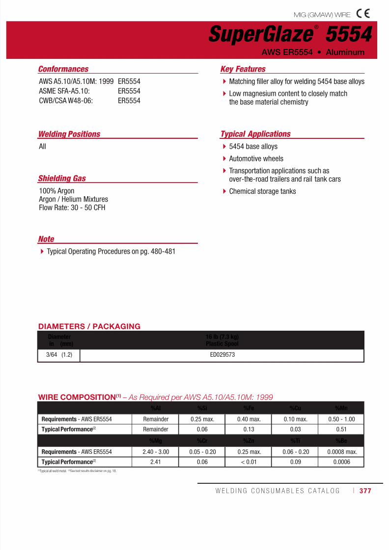
7/18/2019 c110 - Lincoln Electric Consumables 2014
http://slidepdf.com/reader/full/c110-lincoln-electric-consumables-2014 377/511W E L D I N G C O N S U M A B L E S C A TA L O G ı 377
SuperGlaze ®
5554MIG (GMAW) WIRE
Welding Positions Typical Applications
All 5454 base alloys
Automotive wheels
Transportation applications such asover-the-road trailers and rail tank cars
Chemical storage tanks
Matching filler alloy for welding 5454 base alloys
Low magnesium content to closely matchthe base material chemistry
Conformances
Shielding Gas
100% Argon Argon / Helium MixturesFlow Rate: 30 - 50 CFH
AWS ER5554 • Aluminum
Key Features
AWS A5.10/A5.10M: 1999
ASME SFA-A5.10:CWB/CSA W48-06:
ER5554
ER5554ER5554
DIAMETERS / PACKAGING
Diameter 16 lb (7.3 kg)Plastic Spoolin (mm)
3/64 (1.2) ED029573
(1)Typical all weld metal. (2)See test results disclaimer on pg. 18.
WIRE COMPOSITION(1) – As Required per AWS A5.10/A5.10M: 1999
%Al %Si %Fe %Cu %Mn
Requirements - AWS ER5554 Remainder 0.25 max. 0.40 max. 0.10 max. 0.50 - 1.00
Typical Performance(2) Remainder 0.06 0.13 0.03 0.51
%Mg %Cr %Zn %Ti %Be
Requirements - AWS ER5554 2.40 - 3.00 0.05 - 0.20 0.25 max. 0.06 - 0.20 0.0008 max.
Typical Performance(2) 2.41 0.06 < 0.01 0.09 0.0006
Note
Typical Operating Procedures on pg. 480-481

7/18/2019 c110 - Lincoln Electric Consumables 2014
http://slidepdf.com/reader/full/c110-lincoln-electric-consumables-2014 378/511378 ı T H E L I N C O L N E L E C T R I C C O M P A N Y
SuperGlaze ®
5556 MIG (GMAW) WIRE
Welding Positions
Typical Applications All
5XXX alloys, such as 5083 and 5654
Pressure vessels
Storage tanks
Provide matching tensile strengths for5XXX alloys
Increased amounts of magnesium andmanganese
Conformances
Shielding Gas
100% Argon Argon / Helium MixturesFlow Rate: 30 - 50 CFH
Aluminum • AWS ER5556
Key Features
AWS A5.10/A5.10M: 1999
ASME SFA-A5.10: ABS:
ER5556
ER5556IACS W26 Grade WC
DIAMETERS / PACKAGING
Diameter 16 lb (7.3 kg)Plastic Spool
300 lb (136 kg)Gem-Pak™ Boxin (mm)
3/64
1/16
(1.2)
(1.6)
EDS29581
EDS29582
ED034731
(1)Typical all weld metal. (2)See test results disclaimer on pg. 18.
WIRE COMPOSITION(1) – As Required per AWS A5.10/A5.10M: 1999
%Al %Si %Fe %Cu %Mn
Requirements - AWS ER5556 Remainder 0.25 max. 0.40 max. 0.10 max. 0.50 - 1.00
Typical Performance(2) Remainder 0.03 0.13 0.001 0.65
%Mg %Cr %Zn %Ti %Be
Requirements - AWS ER5556 4.70 - 5.50 0.05 - 0.20 0.25 max. 0.05 - 0.20 0.0008 max.
Typical Performance(2) 5.00 0.10 0.02 0.07 0.0006
Note
Typical Operating Procedures on pg. 480-481
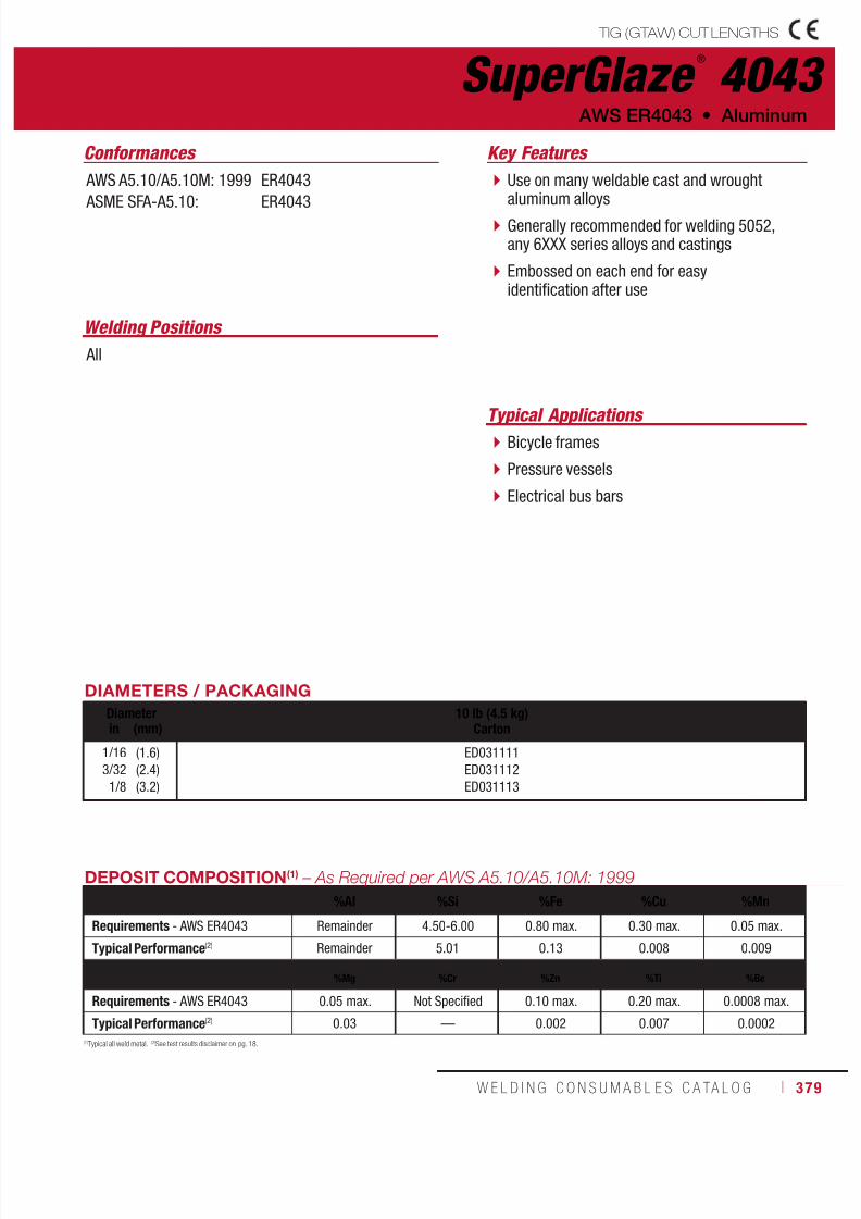
7/18/2019 c110 - Lincoln Electric Consumables 2014
http://slidepdf.com/reader/full/c110-lincoln-electric-consumables-2014 379/511W E L D I N G C O N S U M A B L E S C A TA L O G ı 379
Typical Applications Bicycle frames
Pressure vessels
Electrical bus bars
SuperGlaze ®
4043 TIG (GTAW) CUT LENGTHS
Welding Positions
All
Use on many weldable cast and wroughtaluminum alloys
Generally recommended for welding 5052,any 6XXX series alloys and castings
Embossed on each end for easyidentification after use
Conformances
AWS ER4043 • Aluminum
Key Features
AWS A5.10/A5.10M: 1999
ASME SFA-A5.10:
ER4043
ER4043
DIAMETERS / PACKAGING
Diameter 10 lb (4.5 kg)Cartonin (mm)
1/16
3/32
1/8
(1.6)
(2.4)
(3.2)
ED031111
ED031112
ED031113
(1)Typical all weld metal. (2)See test results disclaimer on pg. 18.
DEPOSIT COMPOSITION(1) – As Required per AWS A5.10/A5.10M: 1999
%Al %Si %Fe %Cu %Mn
Requirements - AWS ER4043 Remainder 4.50-6.00 0.80 max. 0.30 max. 0.05 max.
Typical Performance(2) Remainder 5.01 0.13 0.008 0.009
%Mg %Cr %Zn %Ti %Be
Requirements - AWS ER4043 0.05 max. Not Specified 0.10 max. 0.20 max. 0.0008 max.
Typical Performance(2) 0.03 — 0.002 0.007 0.0002
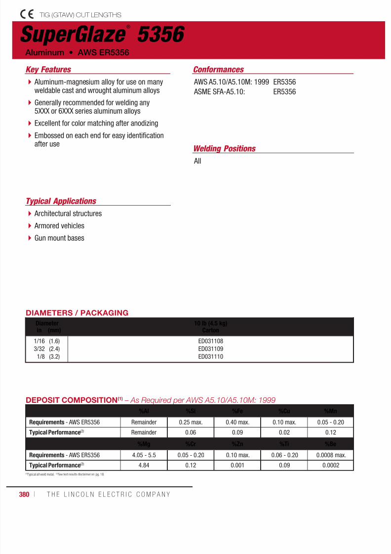
7/18/2019 c110 - Lincoln Electric Consumables 2014
http://slidepdf.com/reader/full/c110-lincoln-electric-consumables-2014 380/511380 ı T H E L I N C O L N E L E C T R I C C O M P A N Y
Typical Applications
Architectural structures
Armored vehicles
Gun mount bases
SuperGlaze ®
5356 TIG (GTAW) CUT LENGTHS
Welding Positions
All
Aluminum-magnesium alloy for use on manyweldable cast and wrought aluminum alloys
Generally recommended for welding any5XXX or 6XXX series aluminum alloys
Excellent for color matching after anodizing
Embossed on each end for easy identificationafter use
Conformances
Aluminum • AWS ER5356
Key Features
AWS A5.10/A5.10M: 1999
ASME SFA-A5.10:
ER5356
ER5356
DIAMETERS / PACKAGING
Diameter 10 lb (4.5 kg)Cartonin (mm)
1/16
3/32
1/8
(1.6)
(2.4)
(3.2)
ED031108
ED031109
ED031110
(1)Typical all weld metal. (2)See test results disclaimer on pg. 18.
DEPOSIT COMPOSITION(1) – As Required per AWS A5.10/A5.10M: 1999
%Al %Si %Fe %Cu %Mn
Requirements - AWS ER5356 Remainder 0.25 max. 0.40 max. 0.10 max. 0.05 - 0.20
Typical Performance(2) Remainder 0.06 0.09 0.02 0.12
%Mg %Cr %Zn %Ti %Be
Requirements - AWS ER5356 4.05 - 5.5 0.05 - 0.20 0.10 max. 0.06 - 0.20 0.0008 max.
Typical Performance(2) 4.84 0.12 0.001 0.09 0.0002

7/18/2019 c110 - Lincoln Electric Consumables 2014
http://slidepdf.com/reader/full/c110-lincoln-electric-consumables-2014 381/511W E L D I N G C O N S U M A B L E S C A TA L O G ı 381
Ferroweld ®
STICK (SMAW) ELECTRODE
Welding Positions Typical Applications
All Repairing pits and small cracks in castings
Deposits may be finished by grinding
Cost effective option for repairing cast iron
Conformances
AWS ESt • Cast Iron
Key Features
AWS A5.15/A5.15M: 1990
ASME SFA-A5.15
ESt
ESt
DIAMETERS / PACKAGING
Diameter 1 lb (0.5 kg) Plastic Tube6 lb (2.7 kg) Master Carton
10 lb (4.5 kg) Easy Open Can30 lb (13.6 kg) Master Cartonin (mm)
1/8 (3.2) ED031542 ED03382
TYPICAL OPERATING PROCEDURES
Electrode Electrode Polarity Current (Amps)
Ferroweld® DC+/AC 80 - 120
7/18/2019 c110 - Lincoln Electric Consumables 2014
http://slidepdf.com/reader/full/c110-lincoln-electric-consumables-2014 382/511382 ı T H E L I N C O L N E L E C T R I C C O M P A N Y
Notes ALUMINUM & CAST IRON CONSUMABLES
7/18/2019 c110 - Lincoln Electric Consumables 2014
http://slidepdf.com/reader/full/c110-lincoln-electric-consumables-2014 383/511W E L D I N G C O N S U M A B L E S C A TA L O G ı 383
CONSUMABLES
PIPELINER®
Stick (SMAW) ElectrodeMild Steel, CellulosicPipeliner® 6P+ ............................................384
Mild Steel, Low HydrogenPipeliner® 16P .............................................. 385
Low Alloy, CellulosicPipeliner® 7P+ ............................................386Pipeliner® 8P+ ............................................387Pipeliner® Arc 80 .......................................... 388
Low Alloy, Low HydrogenPipeliner® 18P .............................................. 390Pipeliner® LH-D80 ........................................391
Pipeliner® LH-D90 ........................................392Pipeliner® 19P .............................................. 393Pipeliner® LH-D100 ......................................394
MIG (GMAW) WireMild and Low Alloy Steel PipePipeliner® 70S-G .........................................395Pipeliner® 80S-G .........................................396Pipeliner® 80Ni1 ..........................................397
Flux-Cored Self-Shielded
(FCAW-S) WireLow Alloy, All PositionPipeliner® NR®-207+ ..................................398Pipeliner® NR®-208-XP ...............................399
Flux-Cored Gas-Shielded(FCAW-G) WireLow Alloy, All PositionPipeliner® 81M ............................................400Pipeliner® 101M ...........................................401
Pipeliner®
111M ...........................................402
Additional InformationElectrode Selection Guide ........................ 404
LH-D80/90/100 Welding Guidelines .......407
EN and ISO Classifications ......................408
Agency Approvals .....................................410
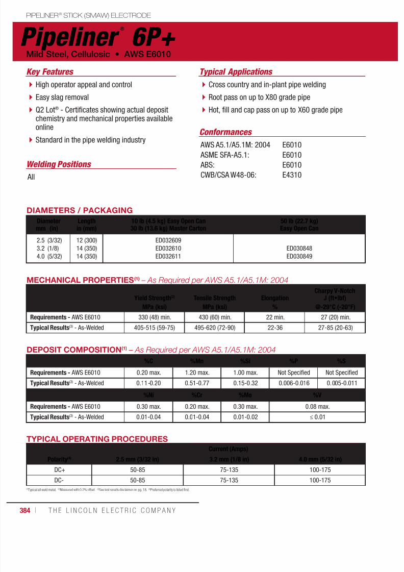
7/18/2019 c110 - Lincoln Electric Consumables 2014
http://slidepdf.com/reader/full/c110-lincoln-electric-consumables-2014 384/511384 ı T H E L I N C O L N E L E C T R I C C O M P A N Y
Pipeliner ®
6P+ PIPELINER® STICK (SMAW) ELECTRODE
Welding Positions
Typical Applications
All
Cross country and in-plant pipe welding
Root pass on up to X80 grade pipe Hot, fill and cap pass on up to X60 grade pipe
High operator appeal and control
Easy slag removal Q2 Lot® - Certificates showing actual depositchemistry and mechanical properties availableonline
Standard in the pipe welding industryConformances
Key Features
AWS A5.1/A5.1M: 2004
ASME SFA-A5.1:
ABS:
CWB/CSA W48-06:
E6010
E6010
E6010
E4310
DIAMETERS / PACKAGING
Diameter Length 10 lb (4.5 kg) Easy Open Can30 lb (13.6 kg) Master Carton
50 lb (22.7 kg)Easy Open Canmm (in) in (mm)
2.5
3.2
4.0
(3/32)
(1/8)
(5/32)
12 (300)
14 (350)
14 (350)
ED032609
ED032610
ED032611
ED030848
ED030849
Mild Steel, Cellulosic • AWS E6010
MECHANICAL PROPERTIES(1) – As Required per AWS A5.1/A5.1M: 2004
Yield Strength(2) Tensile Strength Elongation Charpy V-NotchJ (ft•lbf)
MPa (ksi) MPa (ksi) % @-29°C (-20°F)
Requirements - AWS E6010 330 (48) min. 430 (60) min. 22 min. 27 (20) min.
Typical Results(3) - As-Welded 405-515 (59-75) 495-620 (72-90) 22-36 27-85 (20-63)
DEPOSIT COMPOSITION(1) – As Required per AWS A5.1/A5.1M: 2004
%C %Mn %Si %P %S
Requirements - AWS E6010 0.20 max. 1.20 max. 1.00 max. Not Specified Not Specified
Typical Results(3) - As-Welded 0.11-0.20 0.51-0.77 0.15-0.32 0.006-0.016 0.005-0.011
%Ni %Cr %Mo %V
Requirements - AWS E6010 0.30 max. 0.20 max. 0.30 max. 0.08 max.
Typical Results(3) - As-Welded 0.01-0.04 0.01-0.04 0.01-0.02 ≤ 0.01
TYPICAL OPERATING PROCEDURES
Current (Amps)
Polarity(4) 2.5 mm (3/32 in) 3.2 mm (1/8 in) 4.0 mm (5/32 in)
DC+ 50-85 75-135 100-175
DC- 50-85 75-135 100-175
(1)Typical all weld metal. (2)Measured with 0.2% offset. (3)See test results disclaimer on pg. 18. (4)Preferred polarity is listed first.

7/18/2019 c110 - Lincoln Electric Consumables 2014
http://slidepdf.com/reader/full/c110-lincoln-electric-consumables-2014 385/511W E L D I N G C O N S U M A B L E S C A TA L O G ı 385
(1)Typical all weld metal. (2)Measured with 0.2% offset. (3)See test results disclaimer on pg. 18. (4)Preferred polarity is listed first. (5)DC- for root pass on pipe; DC± for general welding.
Pipeliner ®
16PPIPELINER® STICK (SMAW) ELECTRODE
Welding Positions
Typical Applications
All
Root pass welding of up to X100 grade pipe Hot, fill and cap pass welding up to X60
Low hydrogen, vertical up capability onX60 grade pipe
Q2 Lot® - Certificates showing actual depositchemistry and mechanical properties availableonline
DC- (DCEN) is the recommended polarity forroot pass welding on pipe
Conformances
AWS E7016 H4 • Mild Steel, Low Hydrogen
Key Features
AWS A5.1/A5.1M: 2004
ASME SFA-A5.1:
E7016 H4
E7016 H4
DIAMETERS / PACKAGING
Diameter Length 10 lb (4.5 kg) Easy Open Can30 lb (13.6 kg) Master Carton
12 lb (5.4 kg) Easy Open Can36 lb (16.3 kg) Master Cartonmm (in) in (mm)
2.5
3.2
4.0
(3/32)
(1/8)
(5/32)
14 (350)
14 (350)
18 (450)
ED033835
ED033836
ED033837
TYPICAL OPERATING PROCEDURES
Current (Amps)
Polarity(4) 2.5 mm (3/32 in) 3.2 mm (1/8 in) 4.0 mm (5/32 in)
DC±(5) 55-105 75-135 120-170
AC 60115 80-150 120-185
MECHANICAL PROPERTIES(1) – As Required per AWS A5.1/A5.1M: 2004
Yield Strength(2) Tensile Strength ElongationCharpy V-Notch
J (ft•lbf)
MPa (ksi) MPa (ksi) % @ -29°C (-20°F) @ -40°C (-40°F)Requirements - AWS E7016 H4 400 (58) min. 490 (70) min. 22 min. 27 (20) min. Not Specified
Typical Results(3) - As-Welded 435-545 (63-79) 550-640 (80-93) 23-34 84-161 (62-119) 65-129 (48-95)
DEPOSIT COMPOSITION(1) – As Required per AWS A5.1/A5.1M: 2004
%C %Mn %Si %P %S %Ni
Requirements - AWS E7016 H4 0.15 max. 1.60 max. 0.75 max. 0.035 max. 0.035 max. 0.30 max.
Typical Results(3) - As-Welded 0.04-0.08 1.10-1.60 0.39-0.67 0.005-0.020 0.004-0.012 < 0.07
%Cr %Mo %V
%Mn + Ni + Cr
+ Mo + V
Diffusible Hydrogen
(mL/100g weld metal)Requirements - AWS E7016 H4 0.20 max. 0.30 max. 0.08 max. 1.75 max. 4.0 max.
Typical Results(3) - As-Welded 0.01-0.07 0.01-0.03 0.01-0.02 1.14-1.71 1-4

7/18/2019 c110 - Lincoln Electric Consumables 2014
http://slidepdf.com/reader/full/c110-lincoln-electric-consumables-2014 386/511386 ı T H E L I N C O L N E L E C T R I C C O M P A N Y
PIPELINER® STICK (SMAW) ELECTRODE
Pipeliner ®
7P+
Welding Positions
Typical Applications
All
Root pass welding of up to X80 grade pipe
Hot, fill and cap pass of up to X65 grade pipe Vertical down welding
High productivity in vertical down andout-of-position pipe welding
Deep penetration
Q2 Lot® - Certificates showing actual depositchemistry and mechanical properties availableonline
Clean, visible weld puddle
Superior puddle control
Conformances
Low Alloy, Cellulosic, Pipe • AWS E7010-P1
Key Features
AWS A5.5/A5.5M: 2006
ASME SFA-A5.5:
ABS:
E7010-P1
E7010-P1
E7010-P1
DIAMETERS / PACKAGING
Diameter Length 50 lb (22.7 kg)Easy Open Canmm (in) mm (in)
3.2
4.0
5.0
(1/8)
(5/32)
(3/16)
350 (14)
350 (14)
350 (14)
ED031611
ED031612
ED031613
TYPICAL OPERATING PROCEDURESCurrent (Amps)
Polarity 3.2 mm (1/8 in) 4.0 mm (5/32 in) 5.0 mm (3/16 in)
DC+ 65-130 100-165 130-210
MECHANICAL PROPERTIES
(1)
– As Required per AWS A5.5/A5.5M: 2006
Yield Strength(2) Tensile Strength ElongationCharpy V-Notch
J (ft•lbf)MPa (ksi) MPa (ksi) % @ -29°C (-20°F) @ -40°C (-40°F)
Requirements - AWS E7010-P1 415 (60) min. 490 (70) min. 22 min. 27 (20) min. Not Specified
Typical Results(3) - As-Welded 455-515 (66-75) 525-635 (76-92) 23-29 49-92 (36-68) 31-85 (23-63)
DEPOSIT COMPOSITION(1)
%C %Mn %Si %P %S
Requirements - AWS E7010-P1 0.20 max. 1.20 max. 0.60 max. 0.03 max. 0.03 max.
Typical Results(3) - As-Welded 0.09-0.20 0.44-0.83 0.06-0.31 0.01-0.02 0.01-0.02
%Ni %Cr %Mo %V
Requirements - AWS E7010-P1 1.00 max. 0.30 max. 0.50 max. 0.10 max.
Typical Results(3) - As-Welded 0.58-0.90 0.02-0.05 0.04-0.21 ≤ 0.01
(1)Typical all weld metal. (2)Measured with 0.2% offset. (3)See test results disclaimer on pg. 18.NOTE: This product contains micro-alloying elements. Additional information available upon request.
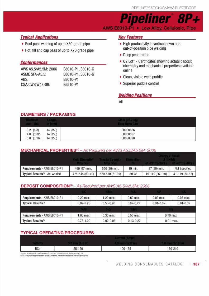
7/18/2019 c110 - Lincoln Electric Consumables 2014
http://slidepdf.com/reader/full/c110-lincoln-electric-consumables-2014 387/511W E L D I N G C O N S U M A B L E S C A TA L O G ı 387
PIPELINER® STICK (SMAW) ELECTRODE
Pipeliner ®
8P+
Welding Positions
Typical Applications
All
Root pass welding of up to X80 grade pipe
Hot, fill and cap pass of up to X70 grade pipe
High productivity in vertical down andout-of-position pipe welding
Deep penetration
Q2 Lot® - Certificates showing actual depositchemistry and mechanical properties availableonline
Clean, visible weld puddle
Superior puddle control
Conformances
AWS E8010-P1 • Low Alloy, Cellulosic, Pipe
Key Features
AWS A5.5/A5.5M: 2006
ASME SFA-A5.5:
ABS:
CSA/CWB W48-06:
E8010-P1, E8010-G
E8010-P1, E8010-G
E8010-P1
E5510-P1
DIAMETERS / PACKAGING
Diameter Length 50 lb (22.7 kg)Easy Open Canmm (in) in (mm)
3.2
4.0
5.0
(1/8)
(5/32)
(3/16)
14 (350)
14 (350)
14 (350)
ED030826
ED030827
ED030828
TYPICAL OPERATING PROCEDURES
Current (Amps)
Polarity 3.2 mm (1/8 in) 4.0 mm (5/32 in) 5.0 mm (3/16 in)
DC+ 65-120 100-165 130-210
MECHANICAL PROPERTIES(1)
– As Required per AWS A5.5/A5.5M: 2006
Yield Strength(2) Tensile Strength ElongationCharpy V-Notch
J (ft•lbf)MPa (ksi) MPa (ksi) % @ -29°C (-20°F) @ -40°C (-40°F)
Requirements - AWS E8010-P1 460 (67) min. 550 (80) min. 19 min. 27 (20) min. Not Specified
Typical Results(3) - As-Welded 475-545 (69-79) 560-670 (81-97) 20-32 49-149 (36-110) 41-119 (30-88)
DEPOSIT COMPOSITION(1) – As Required per AWS A5.5/A5.5M: 2006
%C %Mn %Si %P %S
Requirements - AWS E8010-P1 0.20 max. 1.20 max. 0.60 max. 0.03 max. 0.03 max.
Typical Results(3) 0.09-0.20 0.55-0.98 0.07-0.27 0.01-0.02 0.01-0.02
%Ni %Cr %Mo %V
Requirements - AWS E8010-P1 1.00 max. 0.30 max. 0.50 max. 0.10 max.
Typical Results(3) 0.73-1.00 0.02-0.05 0.13-0.22 0.01 max.
(1)Typical all weld metal. (2)Measured with 0.2% offset. (3)See test results disclaimer on pg. 18.NOTE: This product contains micro-alloying elements. Additional information available on requ est.

7/18/2019 c110 - Lincoln Electric Consumables 2014
http://slidepdf.com/reader/full/c110-lincoln-electric-consumables-2014 388/511388 ı T H E L I N C O L N E L E C T R I C C O M P A N Y
Typical ApplicationsKey Features
Welding Positions
Conformances
Excellent impact properties without the initialaddition of Boron.
High productivity in vertical down andout‐of‐position pipe welding
Deep penetration
Q2 Lot® Control and Tested – Certificateshowing actual deposit chemistry per lotavailable online.
Clean, visible weld puddle
Superior puddle control
Root pass welding of up to X80 grade pipe
Hot, fill and cap pass welding on up to X70grade pipe
AWS A5.5/A5.5M: 2006
ASME SFA‐A5.5:
CSA/CWB W48-06:
E8010‐P1, E8010‐G
E8010‐P1, E8010‐G
E5510-P1, E5510-G
All
DIAMETERS / PACKAGING
Diameter Length 50 lb. (22.7 kg)Easy Open Canin (mm)
4.0 mm (5/32 in)
3/16 in(1)
5.0 mm
14 (350)
14 (350)
14 (350)
ED034456
ED034458
ED034457
Manufactured to US standard units.
PIPELINER® STICK (SMAW) ELECTRODE
Pipeliner ®
Arc 80Low Alloy, Cellulosic, Pipe • AWS E8010-P1, E8010-G

7/18/2019 c110 - Lincoln Electric Consumables 2014
http://slidepdf.com/reader/full/c110-lincoln-electric-consumables-2014 389/511W E L D I N G C O N S U M A B L E S C A TA L O G ı 389
MECHANICAL PROPERTIES(1) – As Required per AWS A5.5/A5.5M: 2006
Yield Strength(2) Tensile Strength ElongationCharpy V-Notch
J (ft•lbf)MPa (ksi) MPa (ksi) % @ ‐29°C (‐20°F) @ -40°C (-40°F)
Requirements AWS E8010‐P1 460 (67) min. 550 (80) min. 19 min. 27 (20) min. Not Specified
Typical Results(3)
As-Welded 475 ‐ 545 (69 ‐ 79) 560 ‐ 670 (81 ‐ 97) 19 ‐ 32 49 ‐ 149 (36 ‐ 110) 41 ‐ 119 (30 ‐ 88)
(1) Typical all weld metal. (2) Measured with 0.2% offset. (3) See test results disclaimer below. (4) Preferred polarity is listed first. (5) Manufactured to US standard units.NOTE: This product contains micro‐alloying elements. Additional information available on request.
DEPOSIT COMPOSITION(1) – As Required per AWS A5.5/A5.5M: 2006
%C %Mn %Si %P %SRequirements AWS E8010‐P1
0.20 max.
1.20 max.
0.60 max.
0.30 max.
0.03 max.
Typical Results(3) 0.09 - 0.20 0.55 - 0.98 0.07 - 0.27 0.01 - 0.02 0.01 - 0.02
%Ni %Cr %Mo %V
Requirements AWS E8010‐P1 1.00 max. 0.30 max. 0.50 max. 0.10 max.
Typical Results(3) 0.73 - 1.00 0.02 - 0.05 0.13 - 0.22 0.01 max.
TYPICAL OPERATING PROCEDURES
Polarity(4)Current (Amps)
4.0 mm (5/32 in) 3/16 in(5) 5.0 mm
DC+ 100-165 125-205 130-210
PIPELINER® STICK (SMAW) ELECTRODE
Pipeliner ®
Arc 80 (AWS E8010-P1)
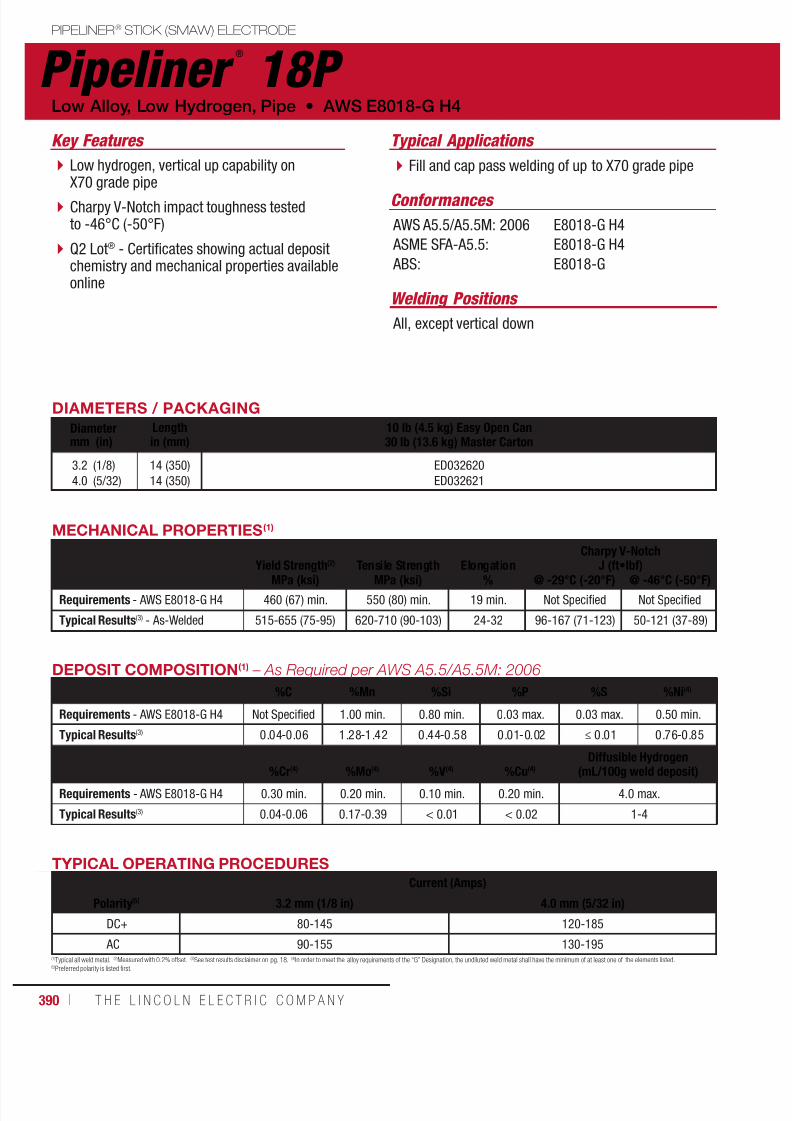
7/18/2019 c110 - Lincoln Electric Consumables 2014
http://slidepdf.com/reader/full/c110-lincoln-electric-consumables-2014 390/511390 ı T H E L I N C O L N E L E C T R I C C O M P A N Y
PIPELINER® STICK (SMAW) ELECTRODE
Pipeliner ®
18P
Welding Positions
Typical Applications
All, except vertical down
Fill and cap pass welding of up to X70 grade pipeLow hydrogen, vertical up capability onX70 grade pipe
Charpy V-Notch impact toughness testedto -46°C (-50°F)
Q2 Lot® - Certificates showing actual depositchemistry and mechanical properties availableonline
Conformances
Low Alloy, Low Hydrogen, Pipe • AWS E8018-G H4
Key Features
AWS A5.5/A5.5M: 2006
ASME SFA-A5.5:
ABS:
E8018-G H4
E8018-G H4
E8018-G
DIAMETERS / PACKAGING
Diameter Length 10 lb (4.5 kg) Easy Open Can30 lb (13.6 kg) Master Cartonmm (in) in (mm)
3.2
4.0
(1/8)
(5/32)
14 (350)
14 (350)
ED032620
ED032621
TYPICAL OPERATING PROCEDURES
Current (Amps)
Polarity(5) 3.2 mm (1/8 in) 4.0 mm (5/32 in)
DC+ 80-145 120-185
AC 90-155 130-195
MECHANICAL PROPERTIES(1)
Yield Strength(2) Tensile Strength ElongationCharpy V-Notch
J (ft•lbf)MPa (ksi) MPa (ksi) % @ -29°C (-20°F) @ -46°C (-50°F)
Requirements - AWS E8018-G H4 460 (67) min. 550 (80) min. 19 min. Not Specified Not Specified
Typical Results(3) - As-Welded 515-655 (75-95) 620-710 (90-103) 24-32 96-167 (71-123) 50-121 (37-89)
(1)Typical all weld metal. (2)Measured with 0.2% offset. (3)See test results disclaimer on pg. 18. (4)In order to meet the alloy requirements of the “G” Designation, the undiluted weld metal shall have the minimum of at least one of the elements listed.(5)Preferred polarity is listed first.
DEPOSIT COMPOSITION(1) – As Required per AWS A5.5/A5.5M: 2006
%C %Mn %Si %P %S %Ni(4)
Requirements - AWS E8018-G H4 Not Specified 1.00 min. 0.80 min. 0.03 max. 0.03 max. 0.50 min.
Typical Results(3) 0.04-0.06 1.28-1.42 0.44-0.58 0.01-0.02 ≤ 0.01 0.76-0.85
%Cr(4) %Mo(4) %V(4) %Cu(4)
Diffusible Hydrogen(mL/100g weld deposit)
Requirements - AWS E8018-G H4 0.30 min. 0.20 min. 0.10 min. 0.20 min. 4.0 max.
Typical Results(3) 0.04-0.06 0.17-0.39 < 0.01 < 0.02 1-4

7/18/2019 c110 - Lincoln Electric Consumables 2014
http://slidepdf.com/reader/full/c110-lincoln-electric-consumables-2014 391/511W E L D I N G C O N S U M A B L E S C A TA L O G ı 391
Pipeliner ®
LH-D80PIPELINER® STICK (SMAW) ELECTRODE
Welding Positions
Typical Applications
Vertical Down
Fill and cap pass weldingon up to X70 grade pipe
Pipe repair
Hot tapping
Low hydrogen, vertical down capability onup to X70 pipe
High productivity
Q2 Lot® - Certificates showing actual depositchemistry and mechanical properties availableonline
Touch start tapered tip
Meets H4R diffusible hydrogen level andmoisture resistance
Conformances
AWS E8045-P2 H4R • Low Alloy, Low Hydrogen, Pipe
Key Features
AWS A5.5/A5.5M: 2006
ASME SFA-A5.5:
CWB/CSA W48-06:
E8045-P2 H4R
E8045-P2 H4R
E8045-P2 H4R
DIAMETERS / PACKAGING
Diameter Length 10 lb (4.5 kg) Easy Open Can30 lb (13.6 kg) Master Cartonmm (in) mm (in)
3.2
4.0
4.5
(1/8)
(5/32)
(11/64)
350 (14)
350 (14)
350 (14)
ED032626
ED032627
ED032628
TYPICAL OPERATING PROCEDURES
Current (Amps)
Polarity 3.2 mm (1/8 in) 4.0 mm (5/32 in) 4.5 mm (11/64 in)
DC+ 120-170 170-250 200-300
MECHANICAL PROPERTIES(1) – As Required per AWS A5.5/A5.5M: 2006
Yield Strength(2) Tensile Strength ElongationCharpy V-Notch
J (ft•lbf)MPa (ksi) MPa (ksi) % @ -29°C (-20°F) @ -46°C (-50°F)
Requirements - AWS E8045-P2 H4R 460 (67) min. 550 (80) min. 19 min. 27 (20) min. Not Specified
Typical Results(3) - As-Welded 485-515 (70-75) 570-600 (83-87) 26-31 75-125 (55-92) 50-95 (37-70)
(1)Typical all weld metal. (2)Measured with 0.2% offset. (3)See test results disclaimer on pg. 18.NOTE: This product contains micro-alloying elements. Additional information available on request.
DEPOSIT COMPOSITION(1) – As Required per AWS A5.5/A5.5M: 2006
%C %Mn %Si %P %S
Requirements - AWS E8045-P2 H4R 0.12 max. 0.90-1.70 0.80 max. 0.03 max. 0.03 max.
Typical Results(3) - As-Welded 0.04-0.06 1.10-1.25 0.35-0.50 ≤ 0.01 ≤ 0.01
%Ni %Cr %Mo %VDiffusible Hydrogen
(mL/100g weld deposit)
Requirements - AWS E8045-P2 H4R 1.00 max. 0.20 max. 0.50 max. 0.05 max. 4.0 max.
Typical Results(3) - As-Welded ≤ 0.04 ≤ 0.05 ≤ 0.02 ≤ 0.01 2-4
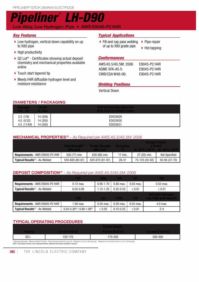
7/18/2019 c110 - Lincoln Electric Consumables 2014
http://slidepdf.com/reader/full/c110-lincoln-electric-consumables-2014 392/511392 ı T H E L I N C O L N E L E C T R I C C O M P A N Y
PIPELINER® STICK (SMAW) ELECTRODE
Pipeliner ®
LH-D90
Welding Positions
Typical Applications
Vertical Down
Fill and cap pass weldingof up to X80 grade pipe
Pipe repair
Hot tapping
Low hydrogen, vertical down capability on upto X80 pipe
High productivity
Q2 Lot® - Certificates showing actual depositchemistry and mechanical properties availableonline
Touch start tapered tip
Meets H4R diffusible hydrogen level andmoisture resistance
Conformances
Low Alloy, Low Hydrogen, Pipe • AWS E9045-P2 H4R
Key Features
AWS A5.5/A5.5M: 2006
ASME SFA-A5.5:
CWB/CSA W48-06:
E9045-P2 H4R
E9045-P2 H4R
E9045-P2 H4R
DIAMETERS / PACKAGING
Diameter Length 10 lb (4.5 kg) Easy Open Can30 lb (13.6 kg) Master Cartonmm (in) in (mm)
3.2
4.0
4.5
(1/8)
(5/32)
(11/64)
14 (350)
14 (350)
14 (350)
ED032629
ED032630
ED032631
MECHANICAL PROPERTIES(1) – As Required per AWS A5.5/A5.5M: 2006
Yield Strength(2) Tensile Strength ElongationCharpy V-Notch
J (ft•lbf)MPa (ksi) MPa (ksi) % @ -29°C (-20°F) @ -46°C (-50°F)
Requirements - AWS E9045-P2 H4R 530 (77) min. 620 (90) min. 17 min. 27 (20) min. Not Specified
Typical Results(3) - As-Welded 550-600 (80-87) 625-670 (91-97) 26-31 75-125 (55-92) 50-95 (37-70)
TYPICAL OPERATING PROCEDURES
Current (Amps)
Polarity 3.2 mm (1/8 in) 4.0 mm (5/32 in) 4.5 mm (11/64 in)
DC+ 120-170 170-250 200-300
(1)Typical all weld metal. (2)Measured with 0.2% offset. (3)See test results disclaimer on pg. 18. (4)Range for 3.2 mm (1/8 in) size only. (5)Range for 4.0 mm (5/32 in) and 4.5 mm (11/64 in) sizes.NOTE: This product contains micro-alloying elements. Additional information available on request.
DEPOSIT COMPOSITION(1) – As Required per AWS A5.5/A5.5M: 2006
%C %Mn %Si %P %S
Requirements - AWS E9045-P2 H4R 0.12 max. 0.90-1.70 0.80 max. 0.03 max. 0.03 max.
Typical Results(3) - As-Welded 0.04-0.06 1.15-1.35 0.35-0.55 ≤ 0.01 ≤ 0.01
%Ni %Cr %Mo %VDiffusible Hydrogen
(mL/100g weld deposit)
Requirements - AWS E9045-P2 H4R 1.00 max. 0.20 max. 0.50 max. 0.05 max. 4.0 max.
Typical Results(3) - As-Welded 0.25-0.30(4) / 0.80-1.00(5) ≤ 0.05 0.15-0.25 ≤ 0.01 2-4
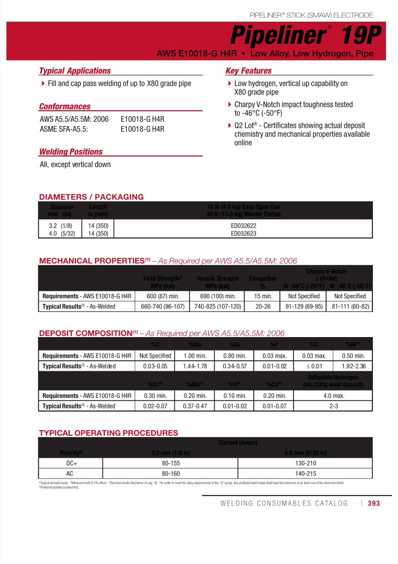
7/18/2019 c110 - Lincoln Electric Consumables 2014
http://slidepdf.com/reader/full/c110-lincoln-electric-consumables-2014 393/511W E L D I N G C O N S U M A B L E S C A TA L O G ı 393
PIPELINER® STICK (SMAW) ELECTRODE
Pipeliner ®
19P
Welding Positions
Typical Applications
All, except vertical down
Fill and cap pass welding of up to X80 grade pipe Low hydrogen, vertical up capability onX80 grade pipe
Charpy V-Notch impact toughness testedto -46°C (-50°F)
Q2 Lot® - Certificates showing actual depositchemistry and mechanical properties availableonline
Conformances
AWS E10018-G H4R • Low Alloy, Low Hydrogen, Pipe
Key Features
AWS A5.5/A5.5M: 2006
ASME SFA-A5.5:
E10018-G H4R
E10018-G H4R
DIAMETERS / PACKAGING
Diameter Length 10 lb (4.5 kg) Easy Open Can30 lb (13.6 kg) Master Cartonmm (in) in (mm)
3.2
4.0
(1/8)
(5/32)
14 (350)
14 (350)
ED032622
ED032623
TYPICAL OPERATING PROCEDURES
Current (Amps)
Polarity(5) 3.2 mm (1/8 in) 4.0 mm (5/32 in)
DC+ 80-155 130-210
AC 80-160 140-215
MECHANICAL PROPERTIES(1) – As Required per AWS A5.5/A5.5M: 2006
Yield Strength(2) Tensile Strength ElongationCharpy V-Notch
J (ft•lbf)
MPa (ksi) MPa (ksi) % @ -29°C (-20°F) @ -46°C (-50°F)Requirements - AWS E10018-G H4R 600 (87) min. 690 (100) min. 15 min. Not Specified Not Specified
Typical Results(3) - As-Welded 660-740 (96-107) 740-825 (107-120) 20-26 91-129 (69-95) 81-111 (60-82)
(1)Typical all weld metal. (2)Measured with 0.2% offset. (3)See test results disclaimer on pg. 18. (4)In order to meet the alloy requirements of the “G” group, the undiluted weld metal shall have the minimum of at least one of the elements listed.(5)Preferred polarity is listed first.
DEPOSIT COMPOSITION(1) – As Required per AWS A5.5/A5.5M: 2006
%C %Mn %Si %P %S %Ni(4)
Requirements - AWS E10018-G H4R Not Specified 1.00 min. 0.80 min. 0.03 max. 0.03 max. 0.50 min.
Typical Results(3) - As-Welded 0.03-0.05 1.44-1.78 0.34-0.57 0.01-0.02 ≤ 0.01 1.92-2.36
%Cr(4)
%Mo(4)
%V(4)
%Cu(4)
Diffusible Hydrogen
(mL/100g weld deposit)Requirements - AWS E10018-G H4R 0.30 min. 0.20 min. 0.10 min. 0.20 min. 4.0 max.
Typical Results(3) - As-Welded 0.02-0.07 0.37-0.47 0.01-0.02 0.01-0.07 2-3
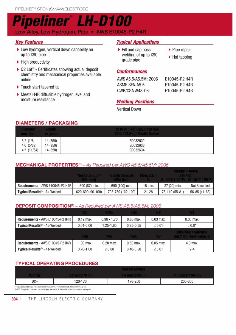
7/18/2019 c110 - Lincoln Electric Consumables 2014
http://slidepdf.com/reader/full/c110-lincoln-electric-consumables-2014 394/511394 ı T H E L I N C O L N E L E C T R I C C O M P A N Y
PIPELINER® STICK (SMAW) ELECTRODE
Pipeliner ®
LH-D100
Welding Positions
Typical Applications
Vertical Down
Fill and cap passwelding of up to X90grade pipe
Pipe repair
Hot tapping
Low hydrogen, vertical down capability onup to X90 pipe
High productivity
Q2 Lot® - Certificates showing actual depositchemistry and mechanical properties availableonline
Touch start tapered tip
Meets H4R diffusible hydrogen level andmoisture resistance
Conformances
Low Alloy, Low Hydrogen, Pipe • AWS E10045-P2 H4R
Key Features
AWS A5.5/A5.5M: 2006
ASME SFA-A5.5:
CWB/CSA W48-06:
E10045-P2 H4R
E10045-P2 H4R
E10045-P2 H4R
DIAMETERS / PACKAGING
Diameter Length 10 lb (4.5 kg) Easy Open Can30 lb (13.6 kg) Master Cartonmm (in) in (mm)
3.2
4.0
4.5
(1/8)
(5/32)
(11/64)
14 (350)
14 (350)
14 (350)
ED032632
ED032633
ED032634
MECHANICAL PROPERTIES(1) – As Required per AWS A5.5/A5.5M: 2006
Yield Strength(2) Tensile Strength Elongation Charpy V-NotchJ (ft•lbf)MPa (ksi) MPa (ksi) % @ -29°C (-20°F) @ -46°C (-50°F)
Requirements - AWS E10045-P2 H4R 600 (87) min. 690 (100) min. 16 min. 27 (20) min. Not Specified
Typical Results(3) - As-Welded 620-690 (90-100) 705-750 (102-109) 21-28 75-110 (55-81) 56-85 (41-63)
TYPICAL OPERATING PROCEDURES
Current (Amps)
Polarity 3.2 mm(1/8 in) 4.0 mm (5/32 in) 4.5 mm (11/64 in)
DC+ 120-170 170-250 200-300
(1)Typical all weld metal. (2)Measured with 0.2% offset. (3)See test results disclaimer on pg. 18.NOTE: This product contains micro-alloying elements. Additional information available on request.
DEPOSIT COMPOSITION(1) – As Required per AWS A5.5/A5.5M: 2006
%C %Mn %Si %P %S
Requirements - AWS E10045-P2 H4R 0.12 max. 0.90 - 1.70 0.80 max. 0.03 max. 0.03 max.
Typical Results(3) - As-Welded 0.04-0.06 1.25-1.65 0.35-0.55 ≤ 0.01 ≤ 0.01
%Ni %Cr %Mo %VDiffusible Hydrogen
(mL/100g weld deposit)
Requirements - AWS E10045-P2 H4R 1.00 max. 0.20 max. 0.50 max. 0.05 max. 4.0 max.
Typical Results(3) - As-Welded 0.70-1.00 ≤ 0.08 0.40-0.50 ≤ 0.01 2-4
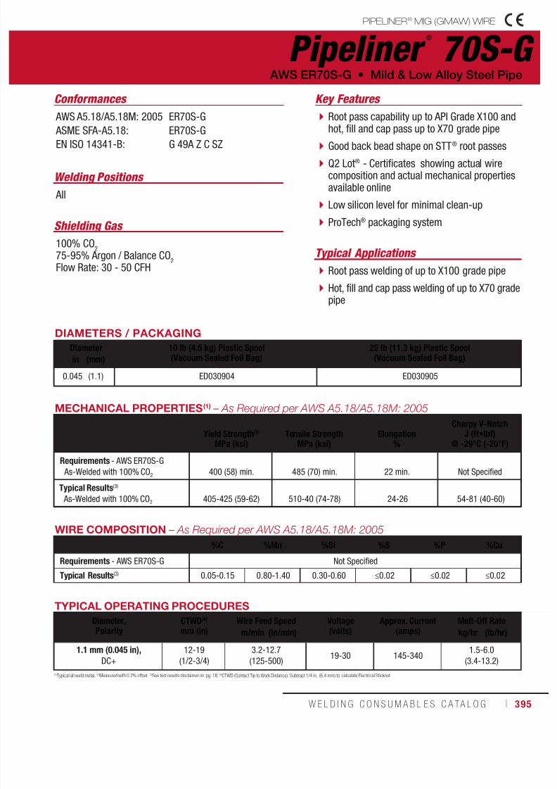
7/18/2019 c110 - Lincoln Electric Consumables 2014
http://slidepdf.com/reader/full/c110-lincoln-electric-consumables-2014 395/511W E L D I N G C O N S U M A B L E S C A TA L O G ı 395
Pipeliner ®
70S-G
Welding Positions
Typical Applications
All
Root pass welding of up to X100 grade pipe
Hot, fill and cap pass welding of up to X70 gradepipe
Root pass capability up to API Grade X100 andhot, fill and cap pass up to X70 grade pipe
Good back bead shape on STT® root passes
Q2 Lot® - Certificates showing actual wirecomposition and actual mechanical propertiesavailable online
Low silicon level for minimal clean-up
ProTech® packaging system
Conformances
Shielding Gas
100% CO2
75-95% Argon / Balance CO2
Flow Rate: 30 - 50 CFH
AWS ER70S-G • Mild & Low Alloy Steel Pipe
Key Features
AWS A5.18/A5.18M: 2005
ASME SFA-A5.18:EN ISO 14341-B:
ER70S-G
ER70S-GG 49A Z C SZ
DIAMETERS / PACKAGING
Diameter 10 lb (4.5 kg) Plastic Spool(Vacuum Sealed Foil Bag)
25 lb (11.3 kg) Plastic Spool(Vacuum Sealed Foil Bag)in (mm)
0.045 (1.1) ED030904 ED030905
WIRE COMPOSITION – As Required per AWS A5.18/A5.18M: 2005
%C %Mn %Si %S %P %Cu
Requirements - AWS ER70S-G Not Specified
Typical Results(3) 0.05-0.15 0.80-1.40 0.30-0.60 ≤0.02 ≤0.02 ≤0.02
MECHANICAL PROPERTIES (1) – As Required per AWS A5.18/A5.18M: 2005
Yield Strength(2)
MPa (ksi)Tensile Strength
MPa (ksi)Elongation
%
Charpy V-NotchJ (ft•lbf)
@ -29°C (-20°F)
Requirements - AWS ER70S-G
As-Welded with 100% CO2
400 (58) min. 485 (70) min.
22 min. Not Specified
Typical Results(3)
As-Welded with 100% CO2 405-425 (59-62) 510-40 (74-78) 24-26 54-81 (40-60)
TYPICAL OPERATING PROCEDURES
Diameter,Polarity
CTWD(4)
mm (in)Wire Feed Speed Voltage
(volts)Approx. Current
(amps)Melt-Off Rate
m/min (in/min) kg/hr (lb/hr)
1.1 mm (0.045 in), DC+
12-19
(1/2-3/4)
3.2-12.7
(125-500)19-30 145-340
1.5-6.0
(3.4-13.2)
(1)Typical all weld metal. (2)Measured with 0.2% offset. (3)See test results disclaimer on pg. 18. (4)CTWD (Contact Tip to Work Distance). Subtract 1/4 in. (6.4 mm) to calculate Electrical Stickout.
PIPELINER® MIG (GMAW) WIRE
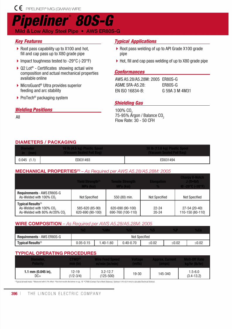
7/18/2019 c110 - Lincoln Electric Consumables 2014
http://slidepdf.com/reader/full/c110-lincoln-electric-consumables-2014 396/511396 ı T H E L I N C O L N E L E C T R I C C O M P A N Y
Pipeliner ®
80S-G
Welding Positions
Typical Applications
All
Root pass welding of up to API Grade X100 gradepipe
Hot, fill and cap pass welding of up to X80 grade pipe
Root pass capability up to X100 and hot,fill and cap pass up to X80 grade pipe
Impact toughness tested to -29°C (-20°F)
Q2 Lot® - Certificates showing actual wirecomposition and actual mechanical propertiesavailable online
MicroGuard® Ultra provides superiorfeeding and arc stability
ProTech® packaging system
Conformances
Shielding Gas
100% CO275-95% Argon / Balance CO
2
Flow Rate: 30 - 50 CFH
Mild & Low Alloy Steel Pipe • AWS ER80S-G
Key Features
AWS A5.28/A5.28M: 2005
ASME SFA-A5.28:
EN ISO 16834-B:
ER80S-G
ER80S-G
G 59A 3 M 4M31
DIAMETERS / PACKAGING
Diameter 10 lb (4.5 kg) Plastic Spool(Vacuum Sealed Foil Bag)
30 lb (13.6 kg) Plastic Spool(Vacuum Sealed Foil Bag)in (mm)
0.045 (1.1) ED031493 ED031494
WIRE COMPOSITION – As Required per AWS A5.28/A5.28M: 2005%C %Mn %Si %S %P %Cu
Requirements - AWS ER80S-G Not Specified
Typical Results(3) 0.05-0.15 1.40-1.60 0.40-0.70 ≤0.02 ≤0.02 ≤0.02
MECHANICAL PROPERTIES(1) – As Required per AWS A5.28/A5.28M: 2005
Yield Strength(2) Tensile Strength ElongationCharpy V-Notch
J (ft•lbf)MPa (ksi) MPa (ksi) % @ -29°C (-20°F)
Requirements - AWS ER80S-G As-Welded with 100% CO2
Not Specified
550 (80) min. Not Specified Not Specified
Typical Results(3)
As-Welded with 100% CO2
As-Welded with 80% Ar/20% CO2
585-620 (85-90)620-690 (90-100)
620-690 (90-100)690-760 (100-110)
22-2420-24
27-54 (20-40)110-150 (80-110)
TYPICAL OPERATING PROCEDURES
Diameter,Polarity
CTWD(4)
mm (in)Wire Feed Speed Voltage
(volts)Approx. Current
(amps)Melt-Off Rate
m/min (in/min) kg/hr (lb/hr)
1.1 mm (0.045 in), DC+
12-19(1/2-3/4)
3.2-12.7(125-500)
19-30 145-3401.5-6.0
(3.4-13.2)
(1)Typical all weld metal. (2)Measured with 0.2% offset. (3)See test results disclaimer on pg. 18. (4)CTWD (Contact Tip to Work Distance). Subtract 1/4 in (6.4 mm) to calculate Electrical Stickout.
PIPELINER® MIG (GMAW) WIRE

7/18/2019 c110 - Lincoln Electric Consumables 2014
http://slidepdf.com/reader/full/c110-lincoln-electric-consumables-2014 397/511W E L D I N G C O N S U M A B L E S C A TA L O G ı 397
Pipeliner ®
80Ni1
Welding Positions
Typical Applications
All
Excellent wire placementfor narrow groove welding
Offshore
Root pass capability up to API Grade X100 andhot, fill and cap pass up to X80 grade pipe
Q2 Lot® - Certificates showing actual wirecomposition and actual mechanical propertiesavailable online
ProTech® packaging system
Conformances
Shielding Gas
75-95% Argon / Balance CO2
100% CO2
AWS ER80S-G • Mild & Low Alloy Steel Pipe
Key Features
AWS A5.28/A5.28M: 2005
ASME SFA-5.28:EN ISO 14341-A:
ABS:
Llyod’s Register:
DNV:
ER80S-G
ER80S-GG 50A 3 M 3Ni1
5YQ500 H5
V Y50MS H5
5Y50S H5
DIAMETERS / PACKAGING
Diameter 10 lb (4.5 kg) Plastic Spool(Vacuum Sealed Foil Bag)
33 lb (15 kg) Plastic Spool(Vacuum Sealed Foil Bag)mm (in)
1.0
1.2
(0.040)
(0.047)
ED033121
ED033122
ED033119
ED033120
WIRE COMPOSITION – As Required per AWS A5.28/A5.28M: 2005
%C %Mn %Si %Ni(4) %Ti %S
Requirements - AWS ER80S-G(4)
EN ISO 14341-A-G 3Ni1Not Specified
0.06-0.14Not Specified
1.00-1.60Not Specified
0.50-0.90≥0.50
0.80-1.50Not Specified
≤0.15Not Specified
≤0.020
Typical Results(3) 0.07-0.08 1.50-1.60 0.65-0.75 0.85-0.95 ≤0.10 ≤0.015
%P %Cu %Cr %Mo %V %AlRequirements - AWS ER80S-G
EN ISO 14341-A-G 3Ni1Not Specified
≤0.020Not Specified
≤0.35Not Specified
≤0.15Not Specified
≤0.15Not Specified
≤0.03Not Specified
≤0.02
Typical Results(3) ≤0.015 ≤0.20 ≤0.05 ≤0.01 ≤0.01 ≤0.01
MECHANICAL PROPERTIES(1) – As Required per AWS A5.28/A5.28M: 2005
Yield Strength(2) Tensile Strength ElongationCharpy V-Notch
J (ft•lbf)MPa (ksi) MPa (ksi) % @ -29°C (-20°F) @ -50°C (-58°F)
Requirements - AWS ER80S-G As-Welded with 100% CO2 Not Specified 550 (80) min. Not Specified Not Specified Not Specified
Typical Results(3)
As-Welded 100% CO2
As-Welded 80% Ar/20% CO2
585-620 (85-90)620-690 (90-100)
620-690 (90-100)690-760 (100-110)
28-2927-28
72-92 (53-68)99-119 (73-88)
34-61 (25-45)69-95 (51-70)
TYPICAL OPERATING PROCEDURES
Diameter, PolarityShielding Gas
CTWD(5)
mm (in)Wire Feed Speed Voltage
(volts)Approx. Current
(amps)Melt-Off Rate
m/min (in/min) kg/hr (lb/hr)
1.0 mm (0.040 in), DC+75-95% Ar/Balance CO2
12-19(1/2-3/4)
2.5-14.0(100-550)
19-31 105-3201.0-5.2
(2.1-11.5)
1.2 mm (0.047 in), DC+75-95% Ar/Balance CO2
12-19(1/2-3/4)
3.2-12.7(125-500)
19-31 145-3601.7-6.5
(3.7-14.3)(1)Typical all weld metal. (2)Measured with 0.2% offset. (3)See test results disclaimer on pg. 18. (4)To meet the ER80S-G classification, weld deposit must have minimum of 1 or more of the following: 0.50% Ni, 0.30% Cr or 0.20% Mo.(5)For Electrical Stickout (ESO) subtract 6.4 mm (0.25 in.) from CTWD. (6)For 100% C0
2 shielding gas add 1 - 2 volts to recommended procedures.
PIPELINER® MIG (GMAW) WIRE

7/18/2019 c110 - Lincoln Electric Consumables 2014
http://slidepdf.com/reader/full/c110-lincoln-electric-consumables-2014 398/511398 ı T H E L I N C O L N E L E C T R I C C O M P A N Y
PIPELINER® FLUX-CORED SELF-SHIELDED (FCAW-S) WIRE
Pipeliner ®
NR ®
-207+Low Alloy, All Position • AWS E71T8-K6
Welding Positions
Typical Applications
All, except vertical up
Hot, fill and cap pass welding of up to X70 grade pipe
Conformances
AWS A5.29/A5.29M: 2005
ASME SFA-A5.29:
E71T8-K6
E71T8-K6
Vertical down hot, fill and cap pass weldingof up to X70 grade pipe
Capable of producing weld deposits withimpact toughness exceeding 27 J (20 ft•lbf)at -29°C (-20°F)
Q2 Lot® - Certificate showing actual depositchemistry and mechanical propertiesavailable online
High deposition rates
ProTech® hermetically sealed packaging
Key Features
DIAMETERS / PACKAGING
Diameter 14 lb (6.4 kg) Coil56 lb (25.4 kg) Hermetically Sealed Pailin (mm)
5/64 (2.0) ED030924
TYPICAL OPERATING PROCEDURES
Diameter,Polarity
CTWD(4)
mm (in)Wire Feed Speed Voltage
(volts)Approx. Current
(amps)Melt-Off Rate
m/min (in/min) kg/hr (lb/hr)
5/64 in (2.0 mm),DC-
19
(3/4)
1.7-3.3
(70 -130)18-21 210-305
2.0-3.7
(4.3-8.1)
(1)Typical all weld metal. (2)Measured with 0.2% offset. (3)See test results disclaimer on pg. 18. (4)For electrical stickout (ESO) subtract 6.4 mm (1/4 in) from contact tip to work distance (CTWD).NOTE: This product contains micro-alloying elements. Additional information available upon request.
DEPOSIT COMPOSITION(1) - As Required per AWS A5.29/A5.29M: 2005
%C %Mn %Si %P %S
Requirements - AWS E71T8-K6 0.15 max. 0.50-1.50 0.80 max. 0.030 max. 0.030 max.
Typical Results(3) 0.04-0.06 1.18-1.33 0.24 - 0.28 ≤ 0.01 ≤ 0.01
%Ni(4) %Cr(4) %Mo(4) %V(4) %Al(4)
Requirements - AWS E71T8-K6 0.40-1.00 0.20 max. 0.15 max. 0.05 max. 1.8 max.
Typical Results(3) 0.78-0.93 0.02-0.03 0.01-0.02 < 0.01 0.9-1.2
MECHANICAL PROPERTIES(1) – As Required per AWS A5.29/A5.29M: 2005
Yield Strength(2)
MPa (ksi)Tensile Strength
MPa (ksi)Elongation
%
Charpy V-NotchJ (ft•lbf)
@ -29°C (-20°F)
Requirements - AWS E71T8-K6 400 (58) min. 485-620 (70-90) 20 min. 27 (20) min.
Typical Results(3) - As-Welded 425-470 (62-68) 540-565 (78-82) 29-31 119-205 (88-151)
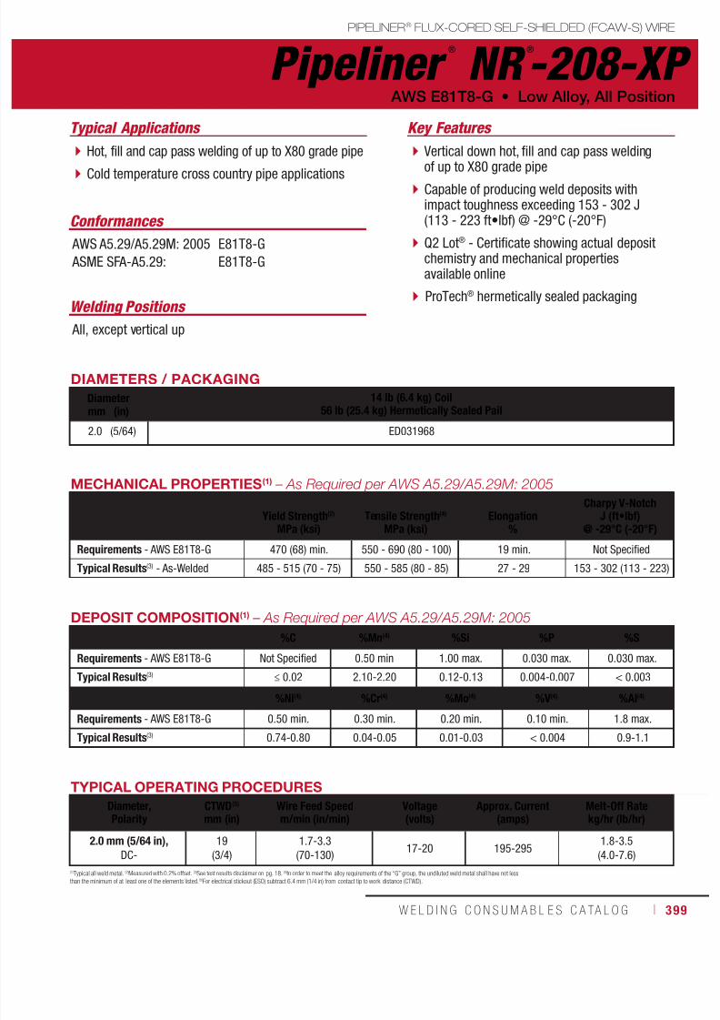
7/18/2019 c110 - Lincoln Electric Consumables 2014
http://slidepdf.com/reader/full/c110-lincoln-electric-consumables-2014 399/511W E L D I N G C O N S U M A B L E S C A TA L O G ı 399
PIPELINER® FLUX-CORED SELF-SHIELDED (FCAW-S) WIRE
Pipeliner ®
NR ®
-208-XP AWS E81T8-G • Low Alloy, All Position
Welding Positions
Typical Applications
All, except vertical up
Hot, fill and cap pass welding of up to X80 grade pipe
Cold temperature cross country pipe applications
Conformances
AWS A5.29/A5.29M: 2005
ASME SFA-A5.29:
E81T8-G
E81T8-G
Vertical down hot, fill and cap pass weldingof up to X80 grade pipe
Capable of producing weld deposits withimpact toughness exceeding 153 - 302 J(113 - 223 ft•lbf) @ -29°C (-20°F)
Q2 Lot® - Certificate showing actual depositchemistry and mechanical propertiesavailable online
ProTech® hermetically sealed packaging
Key Features
DIAMETERS / PACKAGING
Diameter 14 lb (6.4 kg) Coil56 lb (25.4 kg) Hermetically Sealed Pailmm (in)
2.0 (5/64) ED031968
MECHANICAL PROPERTIES(1) – As Required per AWS A5.29/A5.29M: 2005
Yield Strength(2)
MPa (ksi)Tensile Strength(4)
MPa (ksi)Elongation
%
Charpy V-NotchJ (ft•lbf)
@ -29°C (-20°F)
Requirements - AWS E81T8-G 470 (68) min. 550 - 690 (80 - 100) 19 min. Not Specified
Typical Results(3) - As-Welded 485 - 515 (70 - 75) 550 - 585 (80 - 85) 27 - 29 153 - 302 (113 - 223)
TYPICAL OPERATING PROCEDURES
Diameter,Polarity
CTWD(5)
mm (in)Wire Feed Speedm/min (in/min)
Voltage(volts)
Approx. Current(amps)
Melt-Off Ratekg/hr (lb/hr)
2.0 mm (5/64 in),DC-
19
(3/4)
1.7-3.3
(70-130)17-20 195-295
1.8-3.5
(4.0-7.6)
(1)Typical all weld metal. (2)Measured with 0.2% offset. (3)See test results disclaimer on pg. 18. (4)In order to meet the alloy requirements of the “G” group, the undiluted weld metal shall have not lessthan the minimum of at least one of the elements listed. (5)For electrical stickout (ESO) subtract 6.4 mm (1/4 in) from contact tip to work distance (CTWD).
DEPOSIT COMPOSITION(1) – As Required per AWS A5.29/A5.29M: 2005
%C %Mn(4) %Si %P %S
Requirements - AWS E81T8-G Not Specified 0.50 min 1.00 max. 0.030 max. 0.030 max.
Typical Results(3) ≤ 0.02 2.10-2.20 0.12-0.13 0.004-0.007 < 0.003
%Ni(4) %Cr(4) %Mo(4) %V(4) %Al(4)
Requirements - AWS E81T8-G 0.50 min. 0.30 min. 0.20 min. 0.10 min. 1.8 max.
Typical Results(3) 0.74-0.80 0.04-0.05 0.01-0.03 < 0.004 0.9-1.1

7/18/2019 c110 - Lincoln Electric Consumables 2014
http://slidepdf.com/reader/full/c110-lincoln-electric-consumables-2014 400/511400 ı T H E L I N C O L N E L E C T R I C C O M P A N Y
DIAMETERS / PACKAGING
Diameter 10 lb (4.5 kg) Plastic Spool(Vacuum Sealed Foil Bag)
25 lb (11.3 kg) Plastic Spool(Vacuum Sealed Foil Bag)mm (in)
1.2 (0.047) ED033320 ED033321
Pipeliner ®
81M PIPELINER® FLUX-CORED GAS-SHIELDED (FCAW-G) WIRE
Welding Positions
Typical Applications
All
Hot, fill and cap pass welding on up to X70 grade pipe
Fully automated pipe welding Meets requirements for NACE applications
Designed for optimal performance in automatedpipe welding applications where a consistentarc length is critical.
Flat bead shape, fast freezing slag providesconsistent puddle support all the way aroundthe pipe.
Capable of producing weld deposits withimpact toughness exceeding 27 J (20 ft•lbf)at -40°C (-40°F).
Q2 Lot® - Certificate showing actual depositchemistry and mechanical properties per lot
available online. ProTech® foil bag packaging
Conformances
Shielding Gas
75 - 85% Argon / Balance CO2
Flow Rate: 40 - 50 CFH
Low Alloy, All Position • AWS E81T1-GM
Key Features
E81T1-GM
E81T1-GM
ISO 17632-B-T554T1-1MA-N1-UH5
TYPICAL OPERATING PROCEDURES
Diameter, Polarity,Shielding Gas
CTWD(5)
mm (in)Wire Feed Speed Voltage
(volts)Approx. Current
(amps)Melt-Off Rate
m/min (in/min) kg/hr (lb/hr)
1.2 mm (0.047 in), DC+,
75-85% Ar/ balance CO2 19 (3/4)
4.4-10.2
(175 - 400)23-30 130 - 275
1.8-4.1
(3.9-9.0)
(1)Typical all weld metal. (2)Measured with 0.2% offset. (3)See test results disclaimer below. (4)In order to meet the requirements of the G group, the undiluted weld metal shall have not less than the minimum specified for one or more of the elements listed. (5)Strengthand elongation properties were obtained from a 0.500 in. tensile specimen artificially aged at 104°C (220°F) for 48 hours as permitted by AWS A5.29:2005. NOTE: This product contains m icro-alloying elements. Additional information available upon request.
MECHANICAL PROPERTIES(1) – As Required per AWS A5.29/A5.29M: 2010
Yield Strength(2) Tensile Strength ElongationCharpy V-Notch
J (ft•lbf)MPa (ksi) MPa (ksi) % @-29°C (-20°F) @-40°C (-40°F)
Requirements - AWS E81T1-GM 470 (68) min. 550-690 (80-100) 19 min. Not Specified Not Specified
Typical Results(3)
As-Welded with 75% Ar/25% CO2 510-560 (74-81) 580-620 (84-90) 25-29 83-149 (61-110) 66-131 (49-97)
DEPOSIT COMPOSITION(1) – As Required per AWS A5.29/A5.29M: 2010%C %Mn %Si %P
Requirements - AWS E81T1-GM Not Specified 0.50(4) 1.00(4) 0.030 max.
Typical Results(3)
As-Welded with 75% Ar/25% CO2 0.06-0.07 1.54-1.68 0.34-0.37 0.010-0.015
%S %NiDiffusible Hydrogen
(mL/100g weld deposit)
Requirements - AWS E81T1-GM 0.030 max. 0.50(4) Not Specified
Typical Results(3)
As-Welded with 75% Ar/25% CO2 0.010-0.020 0.85 4-5
AWS A5.29/A5.29M: 2010
ASME SFA-5.29
ISO 17632: 2006
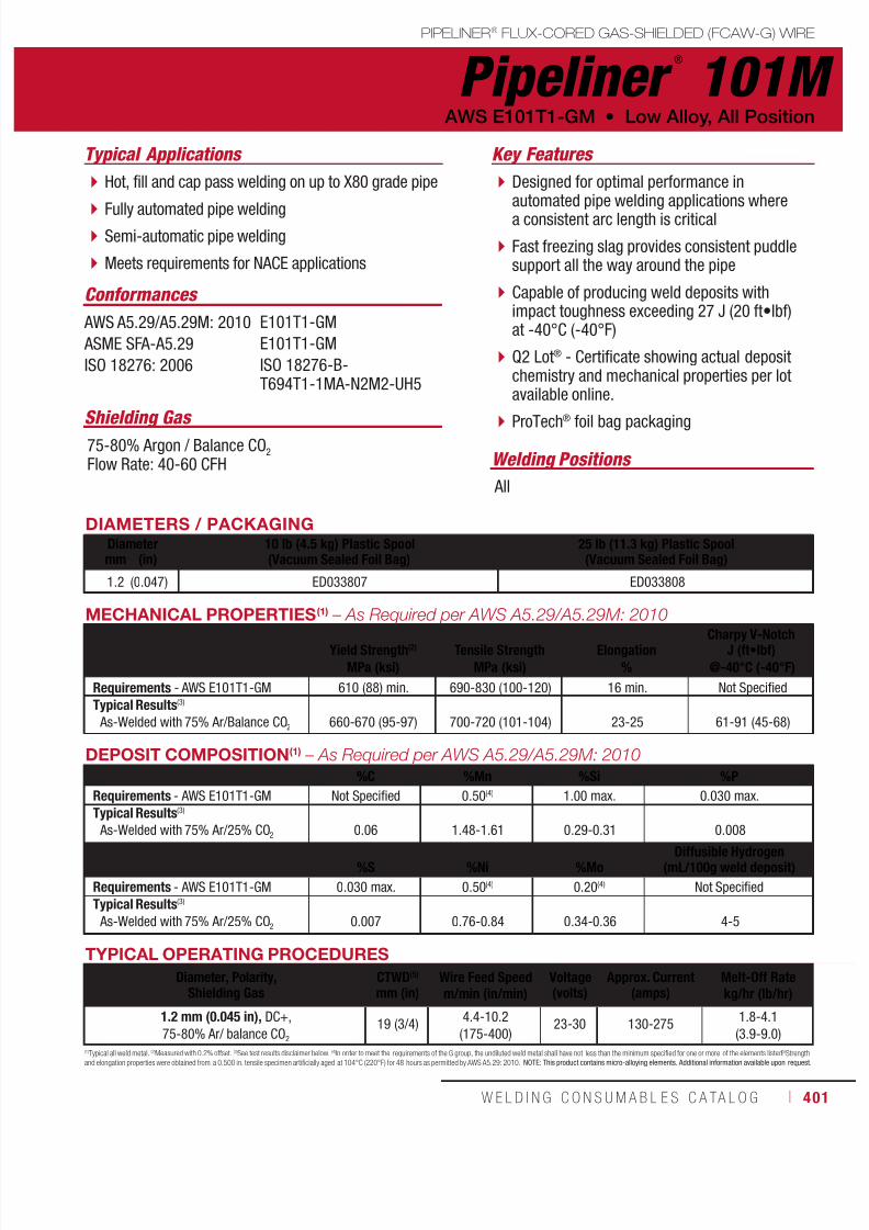
7/18/2019 c110 - Lincoln Electric Consumables 2014
http://slidepdf.com/reader/full/c110-lincoln-electric-consumables-2014 401/511W E L D I N G C O N S U M A B L E S C A TA L O G ı 401
Pipeliner ®
101MPIPELINER® FLUX-CORED GAS-SHIELDED (FCAW-G) WIRE
Welding Positions
Typical Applications
All
Hot, fill and cap pass welding on up to X80 grade pipe
Fully automated pipe welding Semi-automatic pipe welding
Meets requirements for NACE applications
Designed for optimal performance inautomated pipe welding applications wherea consistent arc length is critical
Fast freezing slag provides consistent puddlesupport all the way around the pipe
Capable of producing weld deposits withimpact toughness exceeding 27 J (20 ft•lbf)at -40°C (-40°F)
Q2 Lot® - Certificate showing actual depositchemistry and mechanical properties per lotavailable online.
ProTech® foil bag packaging
Conformances
Shielding Gas 75-80% Argon / Balance CO2
Flow Rate: 40-60 CFH
AWS E101T1-GM • Low Alloy, All Position
Key Features
AWS A5.29/A5.29M: 2010
ASME SFA-A5.29
ISO 18276: 2006
E101T1-GM
E101T1-GM
ISO 18276-B-T694T1-1MA-N2M2-UH5
DIAMETERS / PACKAGINGDiameter 10 lb (4.5 kg) Plastic Spool
(Vacuum Sealed Foil Bag)25 lb (11.3 kg) Plastic Spool(Vacuum Sealed Foil Bag)mm (in)
1.2 (0.047) ED033807 ED033808
MECHANICAL PROPERTIES(1) – As Required per AWS A5.29/A5.29M: 2010
Yield Strength(2) Tensile Strength ElongationCharpy V-Notch
J (ft•lbf)MPa (ksi) MPa (ksi) % @-40°C (-40°F)
Requirements - AWS E101T1-GM 610 (88) min. 690-830 (100-120) 16 min. Not Specified
Typical Results(3)
As-Welded with 75% Ar/Balance CO2 660-670 (95-97) 700-720 (101-104) 23-25 61-91 (45-68)
(1)Typical all weld metal. (2)Measured with 0.2% offset. (3)See test results disclaimer below. (4)In order to meet the requirements of the G group, the undiluted weld metal shall have not less than the minimum specified for one or more of the elements listed. (5)Strengthand elongation properties were obtained from a 0.500 in. tensile specimen artificially aged at 104°C (220°F) for 48 hours as permitted by AWS A5.29: 2010. NOTE: This product contains micro-alloying elements. Additional information available upon request.
DEPOSIT COMPOSITION(1) – As Required per AWS A5.29/A5.29M: 2010
%C %Mn %Si %P
Requirements - AWS E101T1-GM Not Specified 0.50(4) 1.00 max. 0.030 max.
Typical Results(3)
As-Welded with 75% Ar/25% CO2 0.06 1.48-1.61 0.29-0.31 0.008
%S %Ni %MoDiffusible Hydrogen
(mL/100g weld deposit)
Requirements - AWS E101T1-GM 0.030 max. 0.50(4) 0.20(4) Not Specified
Typical Results(3)
As-Welded with 75% Ar/25% CO2 0.007 0.76-0.84 0.34-0.36 4-5
TYPICAL OPERATING PROCEDURES
Diameter, Polarity,Shielding Gas
CTWD(5)
mm (in)Wire Feed Speed Voltage
(volts)Approx. Current
(amps)Melt-Off Rate
m/min (in/min) kg/hr (lb/hr)
1.2 mm (0.045 in), DC+,
75-80% Ar/ balance CO2 19 (3/4)
4.4-10.2
(175-400)23-30 130-275
1.8-4.1
(3.9-9.0)
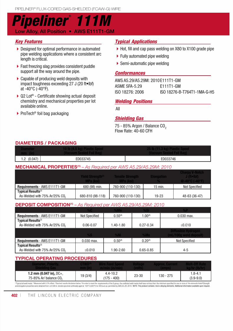
7/18/2019 c110 - Lincoln Electric Consumables 2014
http://slidepdf.com/reader/full/c110-lincoln-electric-consumables-2014 402/511402 ı T H E L I N C O L N E L E C T R I C C O M P A N Y
DIAMETERS / PACKAGING
Diameter 10 lb (4.5 kg) Plastic Spool(Vacuum Sealed Foil Bag)
25 lb (11.3 kg) Plastic Spool(Vacuum Sealed Foil Bag)mm (in)
1.2 (0.047) ED033745 ED033746
Pipeliner ®
111M PIPELINER® FLUX-CORED GAS-SHIELDED (FCAW-G) WIRE
Welding Positions
Typical Applications
All
Hot, fill and cap pass welding on X80 to X100 grade pipe
Fully automated pipe welding Semi-automatic pipe welding
Designed for optimal performance in automatedpipe welding applications where a consistent arclength is critical.
Fast freezing slag provides consistent puddlesupport all the way around the pipe.
Capable of producing weld deposits withimpact toughness exceeding 27 J (20 ft•lbf)at -40°C (-40°F).
Q2 Lot® - Certificate showing actual depositchemistry and mechanical properties per lotavailable online.
ProTech® foil bag packaging
Conformances
Shielding Gas
75 - 85% Argon / Balance CO2
Flow Rate: 40-60 CFH
Low Alloy, All Position • AWS E111T1-GM
Key Features
E111T1-GM
E111T1-GM
ISO 18276-B-T764T1-1MA-G-H5
TYPICAL OPERATING PROCEDURES
Diameter, Polarity,Shielding Gas
CTWD(5)
mm (in)Wire Feed Speed Voltage
(volts)Approx. Current
(amps)Melt-Off Rate
m/min (in/min) kg/hr (lb/hr)
1.2 mm (0.047 in), DC+,
75-85% Ar/ balance CO2 19 (3/4)
4.4-10.2
(175 - 400)23-30 130 - 275
1.8-4.1
(3.9-9.0)
(1)Typical all weld metal. (2)Measured with 0.2% offset. (3)See test results disclaimer below. (4)In order to meet the requirements of the G group, the undiluted weld metal shall have not less than the minimum specified for one or more of the elements listed. (5)Strengthand elongation properties were obtained from a 0.500 in. tensile specimen artificially aged at 104°C (220°F) for 48 hours as permitted by AWS A5.29: 2010. NOTE: This product contains micro-alloying elements. Additional information available upon request.
MECHANICAL PROPERTIES(1) – As Required per AWS A5.29/A5.29M: 2010
Yield Strength(2) Tensile Strength ElongationCharpy V-Notch
J (ft•lbf)MPa (ksi) MPa (ksi) % @-40°C (-40°F)
Requirements - AWS E111T1-GM 680 (98) min. 760-900 (110-130) 15 min. Not Specified
Typical Results(3)
As-Welded with 75% Ar/25% CO2 680-810 (98-118) 760-900 (110-130) 19-23 48-63 (36-47)
DEPOSIT COMPOSITION(1) – As Required per AWS A5.29/A5.29M: 2010%C %Mn %Si %P
Requirements - AWS E111T1-GM Not Specified 0.50(4) 1.00(4) 0.030 max.
Typical Results(3)
As-Welded with 75% Ar/25% CO2 0.06-0.07 1.40-1.80 0.27-0.34 ≤0.010
%S %Ni %MoDiffusible Hydrogen
(mL/100g weld deposit)
Requirements - AWS E111T1-GM 0.030 max. 0.50(4) 0.20(4) Not Specified
Typical Results(3)
As-Welded with 75% Ar/25% CO2 ≤0.010 1.90-2.60 0.65-0.85 4-5
AWS A5.29/A5.29M: 2010
ASME SFA-5.29
ISO 18276: 2006

7/18/2019 c110 - Lincoln Electric Consumables 2014
http://slidepdf.com/reader/full/c110-lincoln-electric-consumables-2014 403/511W E L D I N G C O N S U M A B L E S C A TA L O G ı 403
Additional InformationPIPELINER® CONSUMABLES
Additional Information
Electrode Selection Guide ...................... 404
LH-D80/90/100 Welding Guidelines ....... 407
EN and ISO Classifications ..................... 408
Agency Approvals ................................... 410
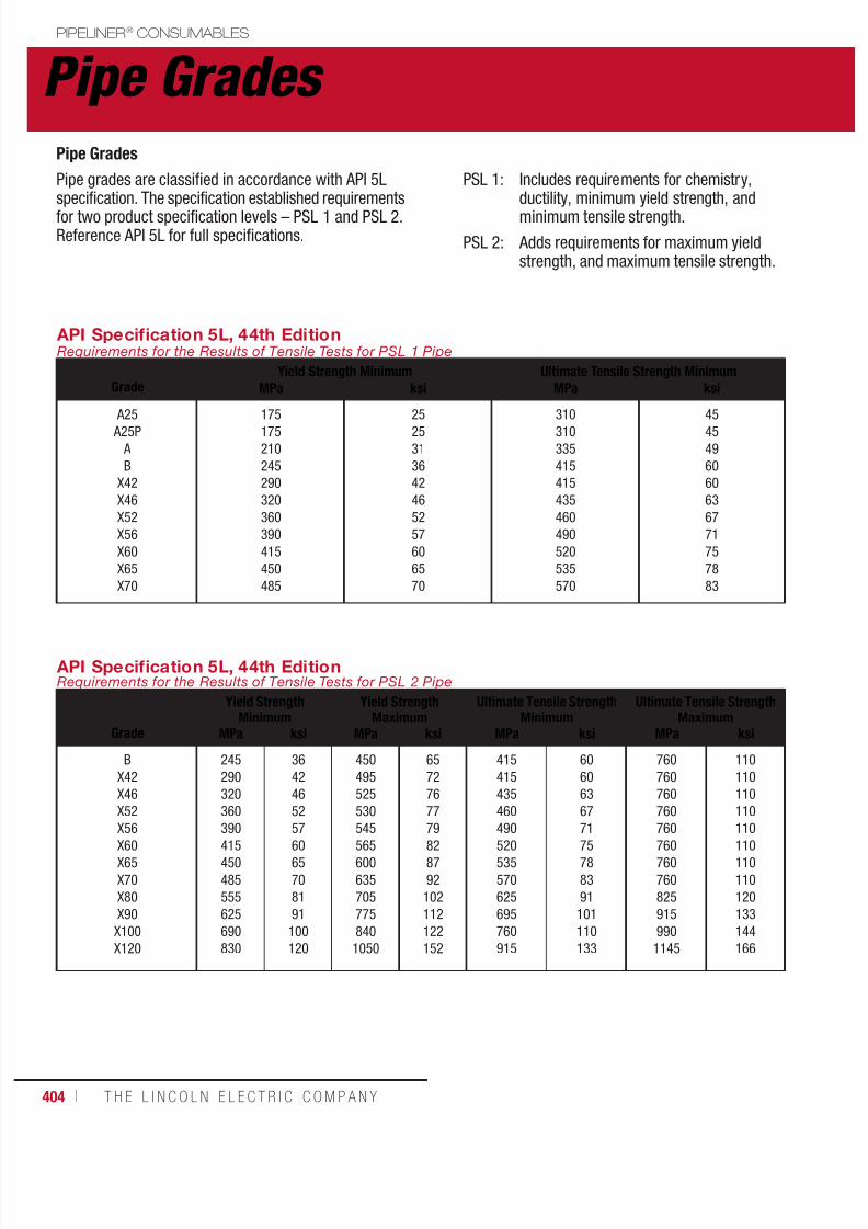
7/18/2019 c110 - Lincoln Electric Consumables 2014
http://slidepdf.com/reader/full/c110-lincoln-electric-consumables-2014 404/511404 ı T H E L I N C O L N E L E C T R I C C O M P A N Y
Pipe Grades PIPELINER® CONSUMABLES
API Specification 5L, 44th EditionRequirements for the Results of Tensile Tests for PSL 1 Pipe
GradeYield Strength Minimum Ultimate Tensile Strength Minimum
MPa ksi MPa ksi
A25 A25P
A
B
X42
X46
X52
X56
X60
X65
X70
175175
210
245
290
320
360
390
415
450
485
2525
31
36
42
46
52
57
60
65
70
310310
335
415
415
435
460
490
520
535
570
4545
49
60
60
63
67
71
75
78
83
API Specification 5L, 44th EditionRequirements for the Results of Tensile Tests for PSL 2 Pipe
Grade
Yield StrengthMinimum
Yield StrengthMaximum
Ultimate Tensile StrengthMinimum
Ultimate Tensile StrengthMaximum
MPa ksi MPa ksi MPa ksi MPa ksi
B
X42
X46
X52
X56
X60X65
X70
X80
X90
X100
X120
245
290
320
360
390
415450
485
555
625
690
830
36
42
46
52
57
6065
70
81
91
100
120
450
495
525
530
545
565600
635
705
775
840
1050
65
72
76
77
79
8287
92
102
112
122
152
415
415
435
460
490
520535
570
625
695
760
915
60
60
63
67
71
7578
83
91
101
110
133
760
760
760
760
760
760760
760
825
915
990
1145
110
110
110
110
110
110110
110
120
133
144
166
Pipe Grades
Pipe grades are classified in accordance with API 5Lspecification. The specification established requirementsfor two product specification levels – PSL 1 and PSL 2.Reference API 5L for full specifications.
PSL 1: Includes requirements for chemistry,ductility, minimum yield strength, andminimum tensile strength.
PSL 2: Adds requirements for maximum yieldstrength, and maximum tensile strength.

7/18/2019 c110 - Lincoln Electric Consumables 2014
http://slidepdf.com/reader/full/c110-lincoln-electric-consumables-2014 405/511W E L D I N G C O N S U M A B L E S C A TA L O G ı 405
Pipe GradesPIPELINER® CONSUMABLES
Common Pipe Joint Designs
60˚
3/64-1/16 in.
(1.0-1.6 mm)
1/16-5/64 in.
(1.6-2.0 mm)
1/16 in.
(1.6 mm)
1/3 T
2/3 T
1/16-5/64 in.(1.6-2.0 mm)
20˚
30˚T
A common weld joint for thinner walled pipe isthe “API” fitup with a 60 degree included angle,
a 1.6 mm (1/16 in) and 1.6 mm (1/16 in).
Wall thickness <3/4 in (<20 mm) Wall thickness >3/4 in (>20 mm)
As an alternative, for thicker-walled pipe [>20 mm(>3/4 in)], a compound bevel can be used. The amount
of material required to fill a compound bevel joint is lessthan that for a 60 degree included angle preparation, soproductivity may be increased.

7/18/2019 c110 - Lincoln Electric Consumables 2014
http://slidepdf.com/reader/full/c110-lincoln-electric-consumables-2014 406/511406 ı T H E L I N C O L N E L E C T R I C C O M P A N Y
Electrode Selection Guide PIPELINER® CONSUMABLES
ELECTRODE SELECTION GUIDE
Products AWS Classification
Low Strength High Strength
<X60 X60 X65 X70 X80 X90 X100
MANUAL ELECTRODES
Stick (SMAW) Electrodes - Cellulosic
Pipeliner® 6P+ E6010 R+F R+F R R R
Pipeliner® 7P+ E7010-P1 R+F R+F R R
Pipeliner® 8P+ E8010-P1 R+F R+F R+F R
Stick (SMAW) Electrodes - Basic, Low Hydrogen, Vertical Up
Pipeliner® 16P E7016 H4 R R R R R R R
Pipeliner® 18P E8018-G H4R F F F
Pipeliner® 19P E10018-G H4R F F F F
Stick (SMAW) Electrodes - Basic, Low Hydrogen, Vertical Down
Pipeliner® LH-D80 E8045-P2 H4R F F F
Pipeliner® LH-D90 E9045-P2 H4R F F F
Pipeliner® LH-D100 E10045-P2 H4R F F F
SEMIAUTOMATIC / AUTOMATIC
MIG (GMAW) Wires - Solid
Pipeliner® 70S-G ER70S-G R+F R+F R+F R+F R R R
Pipeliner® 80S-G ER80S-G R+F R+F R+F R+F R R
Pipeliner® 80Ni1 ER80S-G R+F R+F R+F R+F R R
Flux-Cored (FCAW-S) Wires - Self-Shielded
Pipeliner® NR®-207+ E71T8-K6 F F F
Pipeliner® NR®-208-XP E81T8-G F F F
Flux-Cored (FCAW-G) Wires - Gas-Shielded
Pipeliner® 81M E81T1-GM F F F F
Pipeliner® 101M E101T1-GM F F F F
Pipeliner® 111M E111T1-GM F F F
R = Root Pass Only R+F = Root & Fill Passes F = Fill Pass Only

7/18/2019 c110 - Lincoln Electric Consumables 2014
http://slidepdf.com/reader/full/c110-lincoln-electric-consumables-2014 407/511W E L D I N G C O N S U M A B L E S C A TA L O G ı 407
LH-D80/90/100PIPELINER® CONSUMABLES
Welding Guidelines
Pipeliner ® LH-D Welding - Helpful Hints
Pipeliner® LH-D80, LH-D90 and LH-D100 arelow hydrogen, high deposition electrodes spe-
cially designed for the vertical down welding ofpipe. They are recommended for fill and cap passwelding of up to X70, X80 and X90 pipe, as well aspipe repair and hot tapping applications. For lowdiffusible hydrogen, high productivity and operatorappeal — choose Pipeliner® LH-D electrodes.
Use Recommended Starting andStopping TechniquesPorosity can be the result of incorrect startingor stopping techniques. Refer to Diagram #2and #5 below.
TYPICAL OPERATING PROCEDURES
Current (Amps)
Polarity 3.2 mm (1/8 in) 4.0 mm (5/32 in) 4.5 mm (11/64 in)
DC+ 120 - 170 170 - 250 200 - 300
BREAKING THE ARCBEAD CONTOUR
STARTING THE ARC3 2
5 4
Recommended maximum weave width
is 2X diameter of electrode.
Electrode diameter
WRONGNarrow gap
Touch start tapered
tip in weld crater.0-10°
0 - 1
0 °
0 - 1
0 °
12 o’ clock
3
o’ clock
6
o’ clock
0 - 1 0
°
0-10°
1.6mm ( ⁄” )Max. Arc Length
D i r e
c t i
o n
o f T
r a v e l
I n c r e a s e C u r r e n t
Decrease Current
RIGHTCorrect gap
WEAVE WIDTH
RIGHT WRONG
0-10°
Switch to Push Angle
Welding Guidelines Diagram
NOTE 1: This table indicates common welding electrodes by API 5L pipe grade. Final product selection should be project specific. The specific electroderecommendation depends on project specifications, including strength overmatch and minimum toughness requirements. For help in selecting the appropriateconsumables and other technical questions, please contact our Pipe Welding Application Group at +1.866.635.4709 or email [email protected].
NOTE 2: Please note that the welding consumable recommendations in this table are based on weld metal strength matching the nominal pipe strength basedupon API 5L minimum requirements. Recommended consumables in this chart are based upon these standards and not actual strength of pipe.
Make Sure Operating Procedures are CorrectPipeliner® LH-D electrodes recommended operating
ranges are in the table below.
Do Not Re-Strike ElectrodeIf arc does not initiate on first try, discard electrode andstart with a new one.
Technique Tips for Weld Positions12 o’clock Decreased current and rod angle
will reduce spatter. 3 o’clock Increased current will help hold
weld puddle up. 6 o’clock A push angle and weave will help
flatten bead.
Use the Recommended Weaving TechniqueWeaving too wide can cause undercutting and slagentrapment. Use a maximum weave width ofapproximately 2 times electrode diameter. Refer toDiagram #3 below for directions.

7/18/2019 c110 - Lincoln Electric Consumables 2014
http://slidepdf.com/reader/full/c110-lincoln-electric-consumables-2014 408/511408 ı T H E L I N C O L N E L E C T R I C C O M P A N Y
EN and ISO Classifications PIPELINER® CONSUMABLES
ELECTRODE SELECTION GUIDE
Products EN Classification ISO Classification
Stick (SMAW) Electrodes - Cellulosic Pipeliner® 6P+ EN ISO 2560 ISO 2560
ISO 2560-A-E 38 3 C 2 5
ISO 2560-B-E 43 10 C 2 5
ISO 2560-A-E 38 3 C 2 5
ISO 2560-B-E 43 10 C 2 5
Pipeliner® 7P+ EN ISO 2560 ISO 2560
ISO 2560-A-E 42 3 Z C 2 5
ISO 2560-B-E 49 10-G A U
ISO 2560-A-E 42 3 Z C 2 5
ISO 2560-B-E 49 10-G A U
Pipeliner® 8P+ EN ISO 2560 ISO 2560
ISO 2560-A-E 46 4 Z C 25
ISO 2560-B-E 55 10-G A U
ISO 2560-A-E 46 4 Z C 2 5
ISO 2560-B-E 55 10-G A U
Stick (SMAW) Electrodes - Basic, Low Hydrogen, Vertical Up
Pipeliner® 16P EN ISO 2560 ISO 2560
ISO 2560-A-E 42 4 B 1 2 H5
ISO 2560-B-E 49 16 A U H5
ISO 2560-A-E 42 4 B 1 2 H5
ISO 2560-B-E 49 16 A U H5
Pipeliner® 18P EN ISO 2560 ISO 2560
ISO 2560-A-E 50 6 Mn1Ni B 3 2 H5
ISO 2560-B-E 57 18-G A H5
ISO 2560-A-E 50 6 Mn1Ni B 3 2 H5
ISO 2560-B-E 57 18-G A H5
Pipeliner® 19P EN 757 ISO 18275
EN 757 - E 69 5 Mn2NiMo B 3 2 H5 ISO 18275-A-E 69 5 Mn2NiMo B 3 2 H5
ISO 18275-A-E 83 18-G A H5
Stick (SMAW) Electrodes - Basic, Low Hydrogen, Vertical Down
Pipeliner® LH-D80 EN ISO 2560 ISO 2560
ISO 2560-A-E 46 4 B 4 5 H5
ISO 2560-B-E 55 15 G A H5
ISO 2560-A-E 46 4 B 4 5 H5
ISO 2560-B-E 55 15 G A H5
Pipeliner® LH-D90 EN 757 ISO 18275
EN 757 - E 55 4 Z B 45 H5 ISO 18275-A-E 55 4 Z B 4 5 H5
ISO 18275-B-E 62 15 G A H5
Pipeliner® LH-D100 EN 757 ISO 18275
EN 757 - E 62 4 Mn1NiMo B 45 H5 ISO 18275-A-E 62 4 Mn1NiMo B 4 5 H5
ISO 18275-B-E 69 15 G A H5
NOTE: The presented EN and ISO classifications are only the approximate classifications based on available test results. Specific EN and ISO classification tests were not performed in most cases.

7/18/2019 c110 - Lincoln Electric Consumables 2014
http://slidepdf.com/reader/full/c110-lincoln-electric-consumables-2014 409/511W E L D I N G C O N S U M A B L E S C A TA L O G ı 409
PIPELINER® CONSUMABLES
ELECTRODE SELECTION GUIDE
Products EN Classification ISO Classification
MIG (GMAW) Wires - Solid Pipeliner® 70S-G EN ISO 14341 ISO 14341
ISO 14341-A-G 38A 3 M G2Si
ISO 14341-B-G 49A 3U M G6
ISO 14341-A-G 38A 3 M G2Si
ISO 14341-B-G 49A 3U M G6
Pipeliner® 80S-G EN ISO 14341 ISO 14341
ISO 14341-A-G 50A 3 M G4Mo
ISO 14341-B-G 57A 3U M G4M31
ISO 14341-A-G 50A 3 M G4Mo
ISO 14341-B-G 57A 3U M G4M31
Pipeliner® 80Ni1 EN ISO 14341 ISO 14341
ISO 14341-A-G 3Ni1 ISO 14341-A-G 3Ni1
Flux-Cored (FCAW-S) Wires - Self-Shielded
Pipeliner® NR®-207+ EN ISO 17632 ISO 17632
ISO 17632-A-42 3 1Ni Y N 5 H15
ISO 17632-B-49 3 Ni1 T8 N 1 U H15
ISO 17632-A-42 3 1Ni Y N 5 H15
ISO 17632-B-49 3 Ni1 T8 N 1 U H15
Pipeliner® NR®-208-XP EN ISO 17632 ISO 17632
ISO 17632-A-46 3 Z Y N 5 H15
ISO 17632-B-55 3 G T8 N1 U H15
ISO 17632-A-46 3 Z Y N 5 H15
ISO 17632-B-55 3 G T8 N1 U H15
Flux-Cored (FCAW-G) Wires - Gas-Shielded
Pipeliner® 81M EN ISO 17632 ISO 17632
ISO 17632-A-T46 4 Mn1Ni PM 1 H5
ISO 17632-B-T554T1-1MA-N1-UH5
ISO 17632-A-T46 4 Mn1Ni PM 1 H5
ISO 17632-B-T554T1-1MA-N1-UH5Pipeliner® 101M EN ISO 18276 ISO 18276
ISO 18276-A-T 62 4ZPM 1
ISO 18276-B-T694T1-1MA-N2M2-UH5
ISO 18276-A-T 62 4ZPM 1
ISO 18276-B-T694T1-1MA-N2M2-UH5
Pipeliner® 111M EN ISO 18276 ISO 18276
ISO 18276-A-T 69 4Z PM1- H5
ISO 18276-B-T764T1-1MA-G-H5
ISO 18276-A-T 69 4Z PM1- H5
ISO 18276-B-T764T1-1MA-G-H5
NOTE: The presented EN and ISO classifications are only the approximate classifications based on available test results. Specific EN and ISO classification tests were not performed in most cases.
EN and ISO Classifications

7/18/2019 c110 - Lincoln Electric Consumables 2014
http://slidepdf.com/reader/full/c110-lincoln-electric-consumables-2014 410/511410 ı T H E L I N C O L N E L E C T R I C C O M P A N Y
PRODUCTAWSCode
AWS/ASMECLASS
ABSGrade
Lloyd'sRegisterGrade
DNVGrade GL
Stick Electrode
Pipeliner® 6P+ A5.1/A5.1M: 2004 E6010 E6010 - - -
Pipeliner® 16P A5.1/A5.1M: 2004 E7016 H4 - - - -
Pipeliner® 7P+ A5.5/A5.5M: 2006 E7010-P1 E7010-P1 - - -
Pipeliner® 8P+ A5.5/A5.5M: 2006 E8010-P1, E8010-G E8010-P1 - - -
Pipeliner® Arc 80 A5.5/A5.5M: 2006 E8010‐P1, E8010‐G - - - -
Pipeliner® 18P A5.5/A5.5M: 2006 E8018-G, E8018-G H4 E8018-G - - -
Pipeliner®
LH-D80 A5.5/A5.5M: 2006 E8045-P2 H4R - - - -Pipeliner® LH-D90 A5.5/A5.5M: 2006 E9045-P2 H4R - - - -
Pipeliner® 19P A5.5/A5.5M: 2006 E10018-G H4R - - - -
Pipeliner® LH-D100 A5.5/A5.5M: 2006 E10045-P2 H4R - - - -
MIG & TIG
Pipeliner® 70S-G A5.18/A5.18M: 2005 ER70S-G - - - -
Pipeliner® 80S-G A5.28/A5.28M: 2005 ER80S-G - - - -
Pipeliner® 80Ni1 A5.28/A5.28M: 2005 ER80S-G 5YQ500 H5 V Y50MS H5 5Y50S H5 -
MIG & TIG
Pipeliner® NR®-207+ A5.29/A5.29M: 2005 E71T8-K6 - - - -
Pipeliner® NR®-208-XP A5.29/A5.29M: 2005 E81T8-G - - - -
Pipeliner® 81M A5.29/A5.29M: 2010 E81T1-GM - - - -
Pipeliner® 101M A5.29/A5.29M: 2005 E101T1-GM - - - -
Pipeliner® 111M A5.29/A5.29M: 2005 E111T1-GM - - - -
Agency Approvals NOTE: Approvals are updated periodically.
Consult your Lincoln Electric representative or the latest Approval/Grade revisions.

7/18/2019 c110 - Lincoln Electric Consumables 2014
http://slidepdf.com/reader/full/c110-lincoln-electric-consumables-2014 411/511W E L D I N G C O N S U M A B L E S C A TA L O G ı 411
BVGrade CWB/CSA DB TUV Military
Stick Electrode
- E4310 - - -
- - - - -
- - - - -
E5510-P1 - - -
E5510-P1, E5510-G - - -
- - - - -
- E8045-P2 H4R - - -- E9045-P2 H4R - - -
- - - - -
- E10045-P2 H4R - - -
MIG & TIG
- - - - -
- - - - -
- - - - -
MIG & TIG
- - - - -
- - - - -
- - - - -
- - - - -
- - - - -
Agency ApprovalsNOTE: Approvals are updated periodically.

7/18/2019 c110 - Lincoln Electric Consumables 2014
http://slidepdf.com/reader/full/c110-lincoln-electric-consumables-2014 412/511412 ı T H E L I N C O L N E L E C T R I C C O M P A N Y
Notes PIPELINER® CONSUMABLES
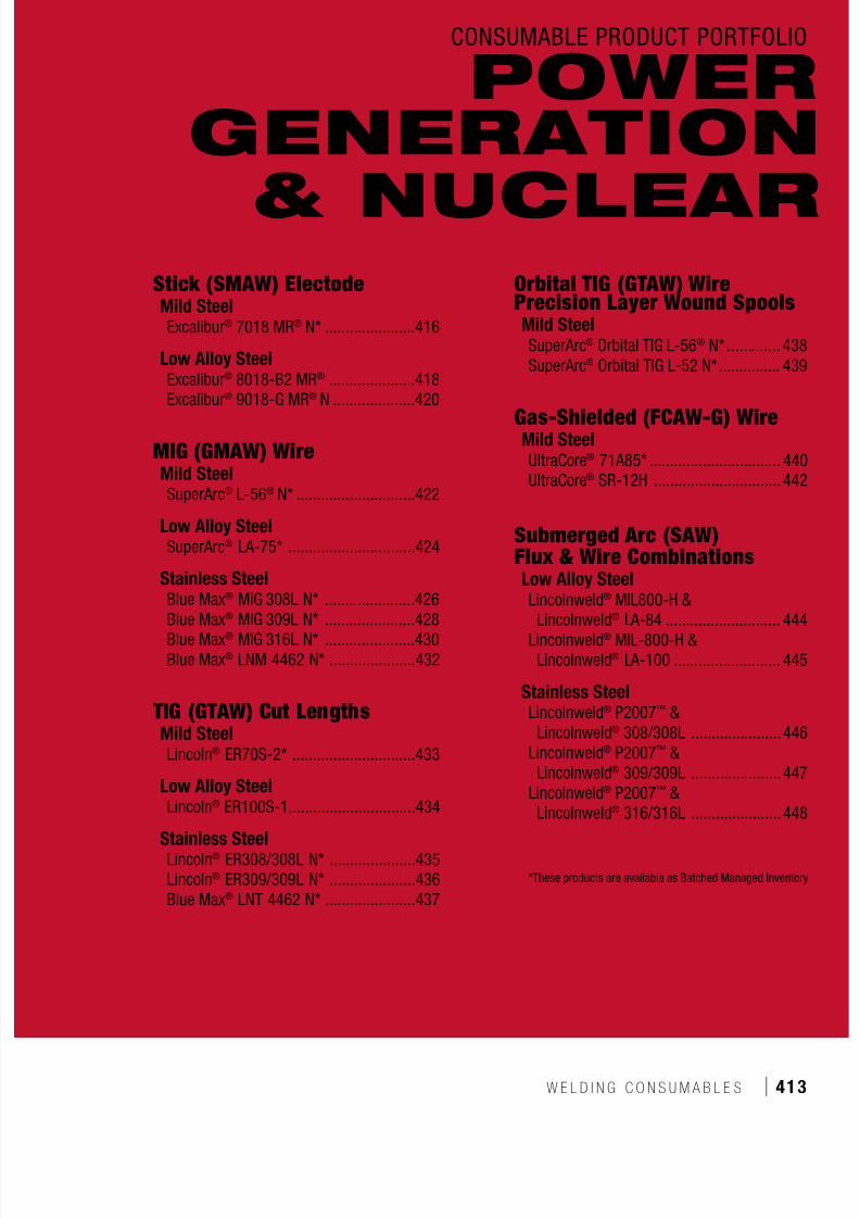
7/18/2019 c110 - Lincoln Electric Consumables 2014
http://slidepdf.com/reader/full/c110-lincoln-electric-consumables-2014 413/511W E L D I N G C O N S U M A B L E S ı 413
CONSUMABLE PRODUCT PORTFOLIO
Stick (SMAW) ElectodeMild SteelExcalibur® 7018 MR® N* ......................416
Low Alloy SteelExcalibur® 8018-B2 MR® .....................418Excalibur® 9018-G MR® N ....................420
MIG (GMAW) WireMild SteelSuperArc® L-56® N* .............................422
Low Alloy SteelSuperArc® LA-75* ...............................424
Stainless SteelBlue Max® MIG 308L N* ......................426
Blue Max®
MIG 309L N* ......................428Blue Max® MIG 316L N* ......................430Blue Max® LNM 4462 N* .....................432
TIG (GTAW) Cut LengthsMild SteelLincoln® ER70S-2* ..............................433
Low Alloy SteelLincoln® ER100S-1...............................434
Stainless SteelLincoln® ER308/308L N* .....................435Lincoln® ER309/309L N* .....................436Blue Max® LNT 4462 N* ......................437
Orbital TIG (GTAW) WirePrecision Layer Wound SpoolsMild SteelSuperArc® Orbital TIG L-56® N* .............438SuperArc® Orbital TIG L-52 N* ............... 439
Gas-Shielded (FCAW-G) WireMild SteelUltraCore® 71A85* ................................ 440UltraCore® SR-12H ............................... 442
Submerged Arc (SAW)Flux & Wire CombinationsLow Alloy SteelLincolnweld® MIL800-H &
Lincolnweld®
LA-84 ............................ 444Lincolnweld® MIL-800-H &Lincolnweld® LA-100 .......................... 445
Stainless SteelLincolnweld® P2007™ &Lincolnweld® 308/308L ......................446
Lincolnweld® P2007™ &Lincolnweld® 309/309L ......................447
Lincolnweld® P2007™ &Lincolnweld® 316/316L ......................448
*These products are available as Batched Managed Inventory
POWERGENERATION
& NUCLEAR

7/18/2019 c110 - Lincoln Electric Consumables 2014
http://slidepdf.com/reader/full/c110-lincoln-electric-consumables-2014 414/511414 ı T H E L I N C O L N E L E C T R I C C O M P A N Y
Lincoln Electric gives customers the ability to view Lot numbers of a specific product online
by going to the Certificate Center under the Support tab and entering the product number.
Customers can then view Q2 Lot Certs by Lot number prior to placing an order.
To place and order please contact your Lincoln Electric
representative to order a specific Lot of product.
Power Generation & Nuclear
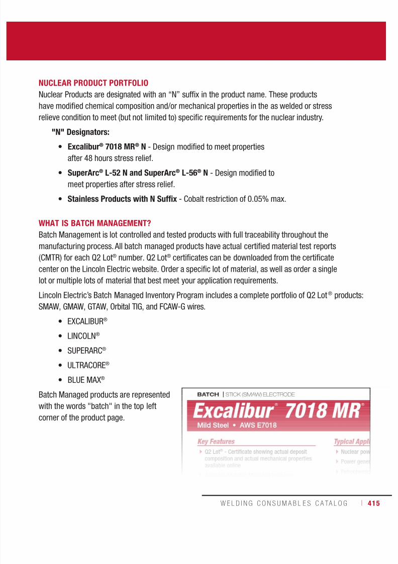
7/18/2019 c110 - Lincoln Electric Consumables 2014
http://slidepdf.com/reader/full/c110-lincoln-electric-consumables-2014 415/511W E L D I N G C O N S U M A B L E S C A TA L O G ı 415
NUCLEAR PRODUCT PORTFOLIO
Nuclear Products are designated with an “N” suffix in the product name. These productshave modified chemical composition and/or mechanical properties in the as welded or stress
relieve condition to meet (but not limited to) specific requirements for the nuclear industry.
"N" Designators:
• Excalibur® 7018 MR® N - Design modified to meet properties
after 48 hours stress relief.
• SuperArc® L-52 N and SuperArc® L-56® N - Design modified to
meet properties after stress relief.
• Stainless Products with N Suffix - Cobalt restriction of 0.05% max.
WHAT IS BATCH MANAGEMENT?Batch Management is lot controlled and tested products with full traceability throughout the
manufacturing process. All batch managed products have actual certified material test reports
(CMTR) for each Q2 Lot® number. Q2 Lot® certificates can be downloaded from the certificate
center on the Lincoln Electric website. Order a specific lot of material, as well as order a single
lot or multiple lots of material that best meet your application requirements.
Lincoln Electric’s Batch Managed Inventory Program includes a complete portfolio of Q2 Lot® products:
SMAW, GMAW, GTAW, Orbital TIG, and FCAW-G wires.
• EXCALIBUR®
• LINCOLN®
• SUPERARC®
• ULTRACORE®
• BLUE MAX®
Batch Managed products are represented
with the words "batch" in the top left
corner of the product page.

7/18/2019 c110 - Lincoln Electric Consumables 2014
http://slidepdf.com/reader/full/c110-lincoln-electric-consumables-2014 416/511416 ı T H E L I N C O L N E L E C T R I C C O M P A N Y
Excalibur ®
7018 MR ®
N BATCH | STICK (SMAW) ELECTRODE
Welding Positions
Typical Applications
All, Except Vertical Down
Nuclear power plant construction and maintenance
Power generation
Petrochemical
Pressure vessels
Pressure piping
Fill and cap pass welding of up to X65 grade pipe
Q2 Lot® - Certificate showing actual deposit
composition and actual mechanical propertiesavailable online
Available as Batch Managed Inventory
“N” Designator - design modified tomeet properties after 48 hours stress relief
Premium arc performance
Square coating burn-off
Easy strike and re-strike
Effortless slag removal
Minimal spatter for enhanced operabilityand clean weld surface
Impact toughness tested to -46°C (-50°F)
Capable of exceeding AWS minimumrequirement of 480 MPa (70 ksi) tensile and400 MPa (58 ksi) yield strength after 48 hoursof stress relieving at 590-620°C (1100-1150°F)
Capable of meeting drop weight testingrequirements as commonly required for
nuclear applications Prior to using this material for ASME Boiler andPressure Vessel Code Section III applications,please contact the Lincoln Electric SpecialsDepartment to receive a Certified Material TestReport (CMTR) which meets all requirementsof NCA-3860.
Each rod is marked with AWS classificationand LOT number
Conformances
Mild Steel • AWS E7018
Key Features
AWS A5.1/A5.1M: 2004:
ASME SFA-A5.1:
E7018 H4R, E7018-1 H4R
E7018 H4R, E7018-1 H4R
ASME IX Qualification: QW432 F-No 4,QW442 A-No 1
ASME IX Qualification
DIAMETERS / PACKAGING
Diameter Length 8 lb (3.6 kg) Easy Open Can24 lb (10.9 kg) Master Carton
10 lb (4.5 kg) Easy Open Can30 lb (13.6 kg) Master Cartonin (mm) in (mm)
3/32
1/8
5/32
(2.4)
(3.2)
(4.0)
12 (300)
14 (350)
14 (350)
ED033940
ED033838
ED033839

7/18/2019 c110 - Lincoln Electric Consumables 2014
http://slidepdf.com/reader/full/c110-lincoln-electric-consumables-2014 417/511W E L D I N G C O N S U M A B L E S C A TA L O G ı 417
STICK (SMAW) ELECTRODE | BATCH
(1)
Typical all weld metal.(2)
Measured with 0.2% offset.(3)
See test results disclaimer on pg. 18.
MECHANICAL PROPERTIES(1) – As Required per AWS A5.1/A5.1M: 2004
Yield Strength(2) Tensile Strength ElongationCharpy V-Notch
J (ft•lbf)MPa (ksi) MPa (ksi) % @ -29°C (-20°F) @ -46°C (-50°F) @ -50°C (-60°F)
Requirements AWS E7018-1 H4R 400 (58) min. 490 (70) min. 22 min. 27 (20) min. 27 (20) min. Not Specified
Typical Results(3)
As-Welded 440-530 (64-77) 540-630 (79-91) 27-29 90-135 (67-233) 28-177 (21-131) 32-210 (24-155)
Stress Relieved
48 hrs @ 620°C (1150°F) 410-470 (59-68) 500-560 (72-81) 29-31 172-352(127-260)
– 23-284(17-210)
DEPOSIT COMPOSITION(1) – As Required per AWS A5.1/A5.1M: 2004
%C %Mn %Si %P %S
Requirements AWS E7018-1 H4R
0.15 max.
1.60 max. 0.75 max. 0.035 max. 0.35 max.
Typical Results(3) 0.06 - 0.08 0.78 - 1.16 0.16 - 0.38 ≤0.01 ≤0.01
%Ni %Cr %MoDiffusible Hydrogen
(mL/100g weld deposit)
Requirements AWS E7018-1 H4R 0.30 max. 0.20 max. 0.30 max. 4.0 max.
Typical Results(3) ≤0.02 ≤0.03 0.20 - 0.25 1 - 3
Excalibur ®
7018 MR ®
N(AWS E7018)
TYPICAL OPERATING PROCEDURES
Current (Amps)
Polarity(4)
3/32 in(2.4 mm)
1/8 in(3.2 mm)
5/32 in(4.0 mm)
DC+ 70-110 90-160 130-210
AC 80-120 100-160 140-210

7/18/2019 c110 - Lincoln Electric Consumables 2014
http://slidepdf.com/reader/full/c110-lincoln-electric-consumables-2014 418/511418 ı T H E L I N C O L N E L E C T R I C C O M P A N Y
Excalibur ®
8018-B2 MR ®
Designed for welding 1.25% chromium,
0.50% molybdenum steel Premium arc performance
Square coating burn-off
Easy strike, re-strike and slag removal
Capable of exceeding AWS minimumrequirement of 550 MPa (80 ksi) tensilestrength after 8 hours of stress-relieving at690°C (1275°F)
Meets AWS minimum requirement of
550 MPa (80 ksi) tensile and 470 MPa (68 Ksi )yield strength after 48 hours of stress-relievingat 590-620°C (1100-1150°F) as typical innuclear applications
Each rod is marked with AWS classificationand LOT number.
Low Alloy Steel • AWS E8018-B2 H4R
Key Features
STICK (SMAW) ELECTRODE
Welding Positions
Typical Applications
All, Except Vertical Down
Power generation
Petrochemical
Pressure vessels
Process piping
Nuclear steam generators and other components
Conformances
AWS A5.5/A5.5M: 2006:
ASME SFA-A5.5:
CWB/CSA W48-06:
E8018-B2 H4R
E8018-B2 H4R
E5518-B2
ASME IX Qualification: QW432 F-No 4,
QW442 A-No 3
ASME IX Qualification
DIAMETERS / PACKAGING
Diameter
Length
8 lb (3.6 kg)
Easy Open Can24 lb (10.9 kg)Master Carton
10 lb (4.5 kg)
Easy Open Can30 lb (13.6 kg)Master Carton
25 lb (11.3 kg)Easy Open Can
50 lb (22.7 kg)Easy Open Canin (mm) in (mm)
3/32
1/8
5/32
(2.4)
(3.2)
(4.0)
12 (300)
14 (350)
14 (350)
ED032878
ED032879
ED032881
ED032882
ED032883

7/18/2019 c110 - Lincoln Electric Consumables 2014
http://slidepdf.com/reader/full/c110-lincoln-electric-consumables-2014 419/511W E L D I N G C O N S U M A B L E S C A TA L O G ı 419
STICK (SMAW) ELECTRODE
Excalibur ®
8018-B2 MR ®
(AWS E8018-B2 H4R)
TYPICAL OPERATING PROCEDURES
Current (Amps)
Polarity(5) 3/32 in (2.4 mm) 1/8 in (3.2 mm) 5/32 in (4.0 mm)
DC+ 60-110 85-160 110-210
AC 65-120 90-170 115-220
(1)Typical all weld metal. (2)Measured with 0.2% offset. (3)See test results disclaimer on pg. 18. (4)Industry Specific Data (Not AWS Requirement). (5)Preferred polarity is listed first.
MECHANICAL PROPERTIES(1) – As Required per AWS A5.5/A5.5M: 2006
Yield Strength(2) Tensile Strength ElongationCharpy V-Notch
J (ft•lbf)MPa (ksi) MPa (ksi) % @ -29°C (-20°F)
Requirements AWS E8018-B2 H4R 460 (67) min. 550 (80) min. 19 min. Not Specified
Typical Results(3) - As-Welded
Stress-Relieved 1 hr @ 690°C (1275°F) 540-585 (78-85) 640-685 (93-99) 24-26 71-127 (52-94)
Stress-Relieved 8 hrs @ 690°C (1275°F)(4) 495-540 (72-78) 605-640 (88-93) 25-28 64-127 (47-83)
Stress-Relieved 48 hrs @ 621°C (1150°F)(4) 560-580 (81-84) 660-680 (96-99) 24-25 28-197 (21-145)
DEPOSIT COMPOSITION(1) – As Required per AWS A5.5/A5.5M: 2006
%C %Mn %Si %P
Requirements AWS E8018-B2 H4R 0.05-0.12 0.90 max. 0.80 max. 0.03 max.
Typical Results(3) 0.08-0.11 0.65-0.80 0.35-0.55 ≤ 0.02
%S %Cr %MoDiffusible Hydrogen
(mL/100g weld metal)
Requirements AWS E8018-B2 H4R 0.03 max. 1.00-1.50 0.40-0.65 4.0 max.
Typical Results(3) ≤ 0.01 1.05-1.30 0.40-0.60 2-4

7/18/2019 c110 - Lincoln Electric Consumables 2014
http://slidepdf.com/reader/full/c110-lincoln-electric-consumables-2014 420/511420 ı T H E L I N C O L N E L E C T R I C C O M P A N Y
Excalibur ®
9018-G MR N
Welding Positions
Typical Applications
All, Except Vertical Down
Nuclear power plant components
High strength steel, such as HY-80, HY-90 and ASTM A514, A508, A533
DC welding
Pressure Vessels
Q2 Lot® - Certificate showing actual deposit
composition and actual mechanical propertiesavailable online
“N” Designator - design modified tomeet properties after 48 hours stress relief
Premium arc performance
Square coating burn-off
Easy strike and re-strike
Effortless slag removal
Capable of exceeding AWS minimumrequirement of 620 MPa (90 ksi) tensile and540 MPa (68 ksi) yield strength after 48 hoursof stress relieving at 590-620°C (1100-1150°F)
Capable of meeting drop weight testingrequirements as commonly required fornuclear applications
Prior to using this material for ASME Boiler andPressure Vessel Code Section III applications,please contact the Lincoln Electric SpecialsDepartment to receive a Certified Material Test
Report (CMTR) which meets all requirementsof NCA-3860
Each rod is marked with AWS classificationand LOT number
Conformances
Low Alloy Steel • AWS E9018-G H4R
Key Features
AWS A5.5/A5.5M: 2006:
ASME SFA-A5.5:
E9018-G H4R
E9018-G H4R
ASME IX Qualification: QW432 F-No 4,QW442 A-No 10
ASME IX Qualification
DIAMETERS / PACKAGING
Diameter Length 8 lb (3.6 kg) Easy Open Can
24 lb (10.9 kg) Master Carton
10 lb (4.5 kg) Easy Open Can
30 lb (13.6 kg) Master Cartonin (mm) in (mm)
3/32
1/8
5/32
(2.4)
(3.2)
(4.0)
12 (300)
14 (350)
14 (350)
ED033897
ED033898
ED033865
STICK (SMAW) ELECTRODE
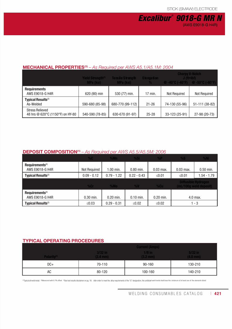
7/18/2019 c110 - Lincoln Electric Consumables 2014
http://slidepdf.com/reader/full/c110-lincoln-electric-consumables-2014 421/511W E L D I N G C O N S U M A B L E S C A TA L O G ı 421
Excalibur ®
9018-G MR N(AWS E9018-G H4R)
(1)
Typical all weld metal.(2)
Measured with 0.2% offset.(3)
See test results disclaimer on pg. 18. (4)In order to meet the alloy requirements of the “G” designation, the undiluted weld metal shall have the minimum of at least one of the elements listed.
DEPOSIT COMPOSITION(1) – As Required per AWS A5.5/A5.5M: 2006
%C %Mn %Si %P %S %Ni
Requirements(4)
AWS E9018-G H4R Not Required 1.00 min. 0.80 min. 0.03 max. 0.03 max. 0.50 min.
Typical Results(3) 0.09 - 0.12 0.79 - 1.22 0.22 - 0.43 ≤0.01 ≤0.01 1.54 - 1.79
%Cr %Mo %V %CuDiffusible Hydrogen
(mL/100g weld deposit)
Requirements(4)
AWS E9018-G H4R 0.30 min. 0.20 min. 0.10 min. 0.20 min. 4.0 max.
Typical Results(3) ≤0.03 0.29 - 0.31 ≤0.02 ≤0.02 1 - 3
MECHANICAL PROPERTIES(1) – As Required per AWS A5.1/A5.1M: 2004
Yield Strength(2) Tensile Strength ElongationCharpy V-Notch
J (ft•lbf)MPa (ksi) MPa (ksi) % @ -40°C (-40°F) @ -50°C (-60°F)
Requirements AWS E9018-G H4R 620 (90) min 530 (77) min. 17 min. Not Required Not Required
Typical Results(3)
As-Welded 590-680 (85-98) 680-770 (99-112) 21-26 74-130 (55-96) 51-111 (38-82)
Stress Relieved48 hrs @ 620°C (1150°F) on HY-80 540-590 (78-85) 630-670 (91-97) 25-28 33-123 (25-91) 27-98 (20-73)
TYPICAL OPERATING PROCEDURES
Current (Amps)
Polarity(4)
3/32 in(2.4 mm)
1/8 in(3.2 mm)
5/32 in(4.0 mm)
DC+ 70-110 90-160 130-210
AC 80-120 100-160 140-210
STICK (SMAW) ELECTRODE

7/18/2019 c110 - Lincoln Electric Consumables 2014
http://slidepdf.com/reader/full/c110-lincoln-electric-consumables-2014 422/511422 ı T H E L I N C O L N E L E C T R I C C O M P A N Y
Q2 Lot® - Certificates showing actual wire
composition and mechanical propertiesavailable online
Available as Batch Managed Inventory
“N” Designator - design modified tomeet properties after stress relief
Uniquely alloyed product to obtain higherstrength levels
High levels of manganese and silicondeoxidizers tolerate medium to heavy millscale surfaces
Excellent toe-wetting provides optimal beadappearance
Copper coated for long contact tip life
Supports short-circuiting, globular, axial sprayand pulsed spray transfer
MicroGuard® Ultra provides superior feedingand arc stability
Each spool is identified with AWS classificationand LOT number
Key Features
BATCH | MIG (GMAW) WIRE
Welding Positions
Typical Applications
All
Nuclear power plant construction and maintenance
Medium to heavy mill scale base material
Robotic or hard automation
Structural steel
Conformances
AWS A5.18/A5.18M: 2005:
ASME SFA-A5.18:
ER70S-6
ER70S-6
ASME IX Qualification: QW432 F-No 6
ASME IX Qualification
SuperArc ®
L-56 ®
N Mild Steel • AWS ER70S-6
DIAMETERS / PACKAGING
Diameter 33 lb (15 kg)
Plastic Spoolin (mm)
0.035
0.045
(0.9)
(1.1)
ED033842
ED033843

7/18/2019 c110 - Lincoln Electric Consumables 2014
http://slidepdf.com/reader/full/c110-lincoln-electric-consumables-2014 423/511W E L D I N G C O N S U M A B L E S C A TA L O G ı 423
MIG (GMAW) WIRE | BATCH
SuperArc ®
L-56 ®
N(AWS ER70S-6)
(1)
Typical all weld metal.(2)
Measured with 0.2% offset.(3)
See test results disclaimer on pg. 18.(4)
Industry specific data, not required by AWS.(5)
Preferred polarity is listed first.NOTE: Additional test data available upon request.
MECHANICAL PROPERTIES(1) – As Required per AWS A5.18/A5.18M: 2005
Yield Strength(2) Tensile Strength ElongationCharpy V-Notch
J (ft•lbf)
MPa (ksi) MPa (ksi) % @ -29°C (-20°F) @ -40°C (-40°F)
Requirements - AWS ER70S-6 As-Welded with 100% CO2 400 (58) min. 485 (70) min. 22 min. 27 (20) min. Not Specified
Typical Results(3)
As-Welded with 100% CO2
Stress Relieved 1 hr. @ 621°C (1150°F)440395
(64)(57)
560510
(81)(74)
2929
7195
(52)(70)
6168
(45)(50)
As-Welded with 75% Ar/25% CO2
Stress Relieved 1 hr. @ 621°C (1150°F)460415
(67)(60)
565540
(82)(78)
2731
82140
(60)(103)
72122
(53)(90)
As-Welded with 90% Ar/10% CO2
Stress Relieved 1 hr. @ 621°C (1150°F)470440
(68)(64)
580550
(84)(80)
2832
119183
(88)(135)
78156
(57)(115)
As-Welded with 98% Ar/2% O2Stress Relieved 1 hr. @ 621°C (1150°F) 455415 (66)(60) 565545 (82)(79) 2734 122190 (90)(140) 108176 (80)(130)
TYPICAL OPERATING PROCEDURES
Diameter, PolarityShielding Gas
CTWD(5)
mm (in)Wire Feed Speed Voltage
(volts)Approx. Current
(amps)Melt-Off Rate
m/min (in/min) kg/hr (lb/hr)
0.035 in (0.9 mm), DC+
Short Circuit Transfer100% CO
2(6)
9-12(3/8-1/2)
2.53.86.4
(100)(150)(250)
181922
80120175
0.71.11.8
(1.6)(2.4)(4.0)
Spray Transfer90% Ar/10% CO
2
12-19(1/2-3/4)
9.512.715.2
(375)(500)(600)
232930
195230275
2.73.64.4
(6.0)(8.0)(9.6)
0.045 in (1.1 mm), DC+
Short Circuit Transfer100% CO
2(6)
12-19(1/2-3/4)
3.23.85.1
(125)(150)(200)
192021
145165200
1.51.82.5
(3.4)(4.0)(5.4)
Spray Transfer90% Ar/10% CO
2
12-19(1/2-3/4)
8.912.112.7
(350)(475)(500)
273030
285335340
4.25.76.0
(9.2)(12.5)(13.2)
WIRE COMPOSITION – As Required per AWS A5.18/A5.18M: 2005
%C %Mn %Si %S %P
Requirements - AWS ER70S-6 0.06-0.15 1.40-1.85 0.80-1.15 0.035 max. 0.025 max.
Typical Results(3) 0.08-0.10 1.42-1.60 0.81-0.87 0.006-0.010 0.004-0.010
%Cr %Ni %Mo %V %Cu (Total)(4)
Requirements - AWS ER70S-6 0.15 max. 0.15 max. 0.15 max. 0.03 max. 0.50 max.
Typical Results(3) 0.01-0.05 ≤ 0.04 ≤ 0.01 < 0.01 0.17-0.22

7/18/2019 c110 - Lincoln Electric Consumables 2014
http://slidepdf.com/reader/full/c110-lincoln-electric-consumables-2014 424/511424 ı T H E L I N C O L N E L E C T R I C C O M P A N Y
Q2 Lot® - Certificates showing actual wire
composition and mechanical propertiesavailable online
Available as Batch Managed Inventory
Capable of producing weld deposits with550 MPa (80 ksi) tensile strength
High toughness at low temperatures witha nominal 1% Ni or less
MicroGuard® Ultra provides superior feedingand arc stability
Supports short-circuiting, globular, axial sprayand pulsed spray transfer
Key Features
Welding Positions Typical Applications
All ASTM A588 weathering steel requiring goodatmospheric corrosion resistance
NACE applications
Nuclear power plant construction and
maintenance
Conformances
ASME IX Qualification: QW432 F-No 6,
QW442 A-No 10
ASME IX Qualification
SuperArc ®
LA-75 Low Alloy Steel • AWS ER80-Ni1
DIAMETERS / PACKAGING
Diameter 33 lb (15 kg)
Plastic Spoolin (mm)
0.035 (0.9) ED033949
AWS A5.28/A5.28M: 2005
ASME SFA-A5.28:
AWS A5.17/A5.17M: 1997
ABS:
CWB/CSA W48-06:
EN ISO 14341-B:
ER80S-Ni1
ER80S-Ni1
ENi1K
ER80S-Ni1
ER55S-Ni1 (ER80S-Ni1)
G 55A 4 A SN2
BATCH | MIG (GMAW) WIRE
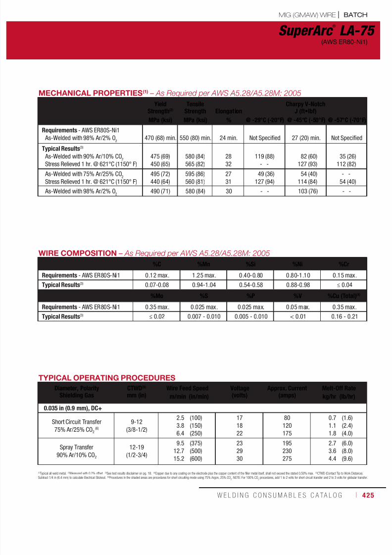
7/18/2019 c110 - Lincoln Electric Consumables 2014
http://slidepdf.com/reader/full/c110-lincoln-electric-consumables-2014 425/511W E L D I N G C O N S U M A B L E S C A TA L O G ı 425
SuperArc ®
LA-75(AWS ER80-Ni1)
MECHANICAL PROPERTIES(1)
– As Required per AWS A5.28/A5.28M: 2005Yield
Strength(2)Tensile
Strength ElongationCharpy V-Notch
J (ft•lbf)
MPa (ksi) MPa (ksi) % @ -29°C (-20°F) @ -45°C (-50°F) @ -57°C (-70°F)
Requirements - AWS ER80S-Ni1
As-Welded with 98% Ar/2% O2
470 (68) min.
550 (80) min.
24 min.
Not Specified
27 (20) min.
Not Specified
Typical Results(3)
As-Welded with 90% Ar/10% CO2
Stress Relieved 1 hr. @ 621°C (1150° F)
475
450
(69)
(65)
580
565
(84)
(82)
28
32
119
-
(88)
-
82
127
(60)
(93)
35
112
(26)
(82)
As-Welded with 75% Ar/25% CO2
Stress Relieved 1 hr. @ 621°C (1150° F)
495
440
(72)
(64)
595
560
(86)
(81)
27
31
49
127
(36)
(94)
54
114
(40)
(84)
-
54
-
(40)
As-Welded with 98% Ar/2% O2 490 (71) 580 (84) 30 - - 103 (76) - -
WIRE COMPOSITION – As Required per AWS A5.28/A5.28M: 2005
%C %Mn %Si %Ni %Cr
Requirements - AWS ER80S-Ni1 0.12 max. 1.25 max. 0.40-0.80 0.80-1.10 0.15 max.
Typical Results(3) 0.07-0.08 0.94-1.04 0.54-0.58 0.88-0.98 ≤ 0.04
%Mo %S %P %V %Cu (Total)(4)
Requirements - AWS ER80S-Ni1 0.35 max. 0.025 max. 0.025 max. 0.05 max. 0.35 max.
Typical Results(3) ≤ 0.02 0.007 - 0.010 0.005 - 0.010 < 0.01 0.16 - 0.21
(1)
Typical all weld metal.(2)
Measured with 0.2% offset.(3)
See test results disclaimer on pg. 18.(4)
Copper due to any coating on the electrode plus the copper content of the filler metal itself, shall not exceed the stated 0.50% max.(5)
CTWD (Contact Tip to Work Distance).Subtract 1/4 in (6.4 mm) to calculate Electrical Stickout. (6)Procedures in the shaded areas are procedures for short circuiting mode using 75% Argon, 25% CO2. NOTE: For 100% CO
2 procedures, add 1 to 2 volts for short circuit transfer and 2 to 3 volts for globular transfer.
TYPICAL OPERATING PROCEDURESDiameter, Polarity
Shielding GasCTWD(5)
mm (in)Wire Feed Speed Voltage
(volts)Approx. Current
(amps)Melt-Off Rate
m/min (in/min) kg/hr (lb/hr)
0.035 in (0.9 mm), DC+
Short Circuit Transfer
75% Ar/25% CO2 (6)
9-12
(3/8-1/2)
2.5
3.8
6.4
(100)
(150)
(250)
17
18
22
80
120
175
0.7
1.1
1.8
(1.6)
(2.4)
(4.0)
Spray Transfer
90% Ar/10% CO2
12-19
(1/2-3/4)
9.5
12.7
15.2
(375)
(500)
(600)
23
29
30
195
230
275
2.7
3.6
4.4
(6.0)
(8.0)
(9.6)
MIG (GMAW) WIRE | BATCH

7/18/2019 c110 - Lincoln Electric Consumables 2014
http://slidepdf.com/reader/full/c110-lincoln-electric-consumables-2014 426/511426 ı T H E L I N C O L N E L E C T R I C C O M P A N Y
Q2 Lot® - Certificate showing actual wire
composition and calculated ferrite number(FN) available online
Available as Batch Managed Inventory
“N” Designator - cobalt restriction of0.05% max
Meets the low Si levels typically required inthe nuclear industry
Meets the low cobalt levels typically requiredin the nuclear industry.
Prior to using this material for ASME Boiler andPressure Vessel Code Section III applications,please contact the Lincoln Electric SpecialsDepartment to receive a Certified Material TestReport (CMTR) which meets all requirementsof NCA-3860
Composition controlled to meet nuclear andpower generation requirements
Each spool is identified with AWSclassification and LOT number
Key Features
Welding Positions
Typical Applications
All
Nuclear power plant components, maintenance
and construction Power and process industry related piping
Pressure Vessels
Conformances
ASME IX Qualification: QW432 F-No 6,QW442 A-No 8
ASME IX Qualification
Blue Max ®
MIG 308L N Stainless Steel • AWS ER308/ER308L
DIAMETERS / PACKAGING
Diameter 33 lb (15 kg)Steel Spoolin (mm)
0.0350.045
(0.9)(1.1)
ED033848ED033849
AWS A5.9/A5.9M: 2006:
ASME SFA-A5.9:
ER308, ER308L
ER308, ER308L
MECHANICAL PROPERTIES(1) – As Required per AWS A5.9/A5.9M: 2006
Yield Strength(2)
MPa (ksi)Tensile Strength
MPa (ksi)Elongation
%Ferrite
Number
Requirements - AWS ER308/308L Not Specified
Test Results(3) - As-Welded 430 (62) 615 (89) 37 13
BATCH | MIG (GMAW) WIRE

7/18/2019 c110 - Lincoln Electric Consumables 2014
http://slidepdf.com/reader/full/c110-lincoln-electric-consumables-2014 427/511W E L D I N G C O N S U M A B L E S C A TA L O G ı 427
Blue Max ®
MIG 308L N(AWS ER308/ER308L)
(1)
Typical all weld metal.(2)
Measured with 0.2% offset.(3)
See test results disclaimer on pg. 18.(4)
Copper due to any coating on the electrode plus the copper content of the filler metal itself, shall not exceed the stated 0.50% max.(5)
CTWD (Contact Tip to Work Distance).Subtract 1/4 in (6.4 mm) to calculate Electrical Stickout. (6)Procedures in the shaded areas are procedures for short circuiting mode using 75% Argon, 25% CO2. NOTE: For 100% CO
2 procedures, add 1 to 2 volts for short circuit transfer and 2 to 3 volts for globular transfer.
IMPORTANT: SPECIAL VENTILATION AND/OR EXHAUST REQUIRED
Fumes from the normal use of some welding products can contain significant quantities of components - such as chromium and manganese - which can lower the 5.0 mg/m3 maximum exposure guideline for general welding fume.
BEFORE USE, READ AND UNDERSTAND THE MATERIAL SAFETY DATA SHEET (MSDS) FOR THIS PRODUCT AND SPECIFIC INFORMATION PRINTED ON THE PRODUCT CONTAINER.
TYPICAL OPERATING PROCEDURES
Diameter, PolarityShielding Gas
CTWD(5)
mm (in)Wire Feed Speed Voltage
(Volts)Approx. Current
(Amps)Deposition Rate
m/min (in/min) kg/hr (lb/hr)
Short Circuit Transfer
0.035 in (0.9 mm), DC+
90% He / 7-1/2% Ar / 2-1/2% CO2
13 (1/2)
13 (1/2)
13 (1/2)
13 (1/2)
13 (1/2)
13 (1/2)
3.0
4.6
5.8
7.6
8.9
10.2
(120)
(180)
(230)
(300)
(350)
(400)
19-20
19-20
20-21
20-21
21-22
22-23
55
85
105
125
140
160
0.9
1.4
1.8
2.3
2.7
3.1
(2.0)
(3.0)
(3.9)
(5.0)
(5.9)
(6.7)
0.045 in (1.1 mm), DC+
90% He / 7-1/2% Ar / 2-1/2% CO2
13 (1/2)
13 (1/2)
13 (1/2)
13 (1/2)
13 (1/2)
13 (1/2)
13 (1/2)
2.5
3.2
3.8
4.4
5.6
6.4
7.0
(100)
(125)
(150)
(175)
(220)
(250)
(275)
19-20
19-20
21
21
22
22-23
22-23
100
120
135
140
170
175
185
1.1
1.5
1.7
2.0
2.6
2.9
3.2
(2.8)
(3.5)
(4.2)
(4.8)
(6.1)
(6.9)
(7.6)
Axial Spray Transfer
0.035 in (0.9 mm), DC+
98% Ar/2% O2
13 (1/2)
13 (1/2)
13 (1/2)13 (1/2)
10.2
10.8
11.412.1
(400)
(425)
(450)(475)
22
23
2323
180
190
200210
3.1
3.3
3.53.7
(6.7)
(7.1)
(7.5)(8.0)
0.045 in (1.1 mm), DC+
98% Ar/2% O2
13 (1/2)
13 (1/2)
13 (1/2)
13 (1/2)
13 (1/2)
6.1
6.6
7.6
8.3
9.1
(240)
(260)
(300)
(325)
(360)
23
24
24
25
25
195
230
240
250
260
2.8
3.0
3.5
3.8
4.2
(6.6)
(7.2)
(8.3)
(9.0)
(10.0)
MIG (GMAW) WIRE | BATCH
WIRE COMPOSITION – As Required per AWS A5.9/A5.9M: 2006
%C %Cr %Ni %Mo %Mn
Requirements - AWS ER308L 0.03(2) max. 19.5 - 22.0 9.0 -11.0 0.75 max. 1.0 - 2.5
Test Results(1) 0.02 20.2 9.2 0.03 1.6
%Si %P %S %Cu Total Others
Requirements - AWS ER308L 0.30 - 0.65 0.03 max. 0.03 max. 0.75 max. 0.50 max.
Test Results(1) 0.44 0.02 0.02 0.11 0.03
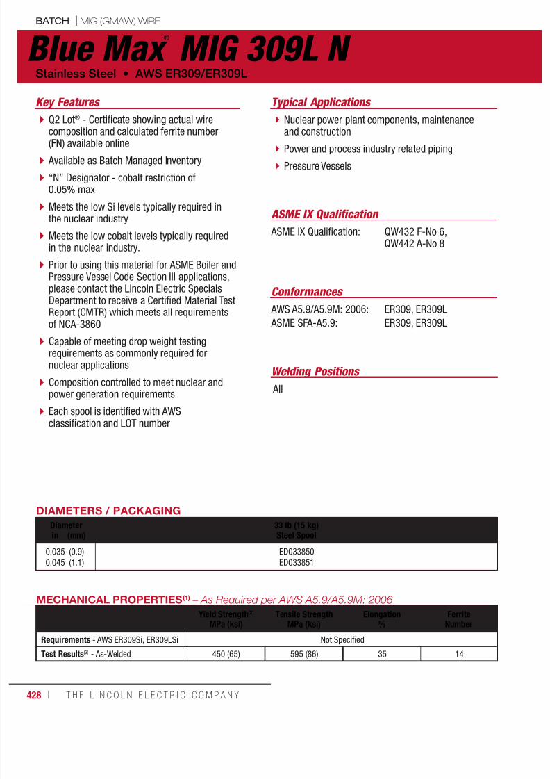
7/18/2019 c110 - Lincoln Electric Consumables 2014
http://slidepdf.com/reader/full/c110-lincoln-electric-consumables-2014 428/511428 ı T H E L I N C O L N E L E C T R I C C O M P A N Y
Q2 Lot® - Certificate showing actual wire
composition and calculated ferrite number(FN) available online
Available as Batch Managed Inventory
“N” Designator - cobalt restriction of0.05% max
Meets the low Si levels typically required inthe nuclear industry
Meets the low cobalt levels typically requiredin the nuclear industry.
Prior to using this material for ASME Boiler andPressure Vessel Code Section III applications,please contact the Lincoln Electric SpecialsDepartment to receive a Certified Material TestReport (CMTR) which meets all requirementsof NCA-3860
Capable of meeting drop weight testingrequirements as commonly required fornuclear applications
Composition controlled to meet nuclear and
power generation requirements Each spool is identified with AWSclassification and LOT number
Key Features
Welding Positions
Typical Applications
All
Nuclear power plant components, maintenance
and construction Power and process industry related piping
Pressure Vessels
Conformances
ASME IX Qualification: QW432 F-No 6,QW442 A-No 8
ASME IX Qualification
Blue Max ®
MIG 309L N Stainless Steel • AWS ER309/ER309L
DIAMETERS / PACKAGING
Diameter 33 lb (15 kg)
Steel Spoolin (mm)
0.035
0.045
(0.9)
(1.1)
ED033850
ED033851
AWS A5.9/A5.9M: 2006:
ASME SFA-A5.9:
ER309, ER309L
ER309, ER309L
MECHANICAL PROPERTIES(1) – As Required per AWS A5.9/A5.9M: 2006
Yield Strength(2)
MPa (ksi)Tensile Strength
MPa (ksi)Elongation
%Ferrite
Number
Requirements - AWS ER309Si, ER309LSi Not Specified
Test Results(3) - As-Welded 450 (65) 595 (86) 35 14
BATCH | MIG (GMAW) WIRE
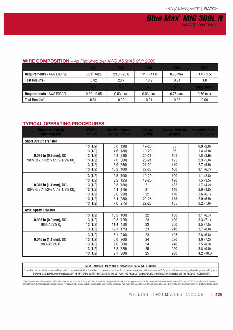
7/18/2019 c110 - Lincoln Electric Consumables 2014
http://slidepdf.com/reader/full/c110-lincoln-electric-consumables-2014 429/511W E L D I N G C O N S U M A B L E S C A TA L O G ı 429
Blue Max ®
MIG 309L N(AWS ER309/ER309L)
(1)
Typical all weld metal.(2)
Measured with 0.2% offset.(3)
See test results disclaimer on pg. 18.(4)
Copper due to any coating on the electrode plus the copper content of the filler metal itself, shall not exceed the stated 0.50% max.(5)
CTWD (Contact Tip to Work Distance).Subtract 1/4 in (6.4 mm) to calculate Electrical Stickout. (6)Procedures in the shaded areas are procedures for short circuiting mode using 75% Argon, 25% CO2. NOTE: For 100% CO
2 procedures, add 1 to 2 volts for short circuit transfer and 2 to 3 volts for globular transfer.
IMPORTANT: SPECIAL VENTILATION AND/OR EXHAUST REQUIRED
Fumes from the normal use of some welding products can contain significant quantities of components - such as chromium and manganese - which can lower the 5.0 mg/m3 maximum exposure guideline for general welding fume.
BEFORE USE, READ AND UNDERSTAND THE MATERIAL SAFETY DATA SHEET (MSDS) FOR THIS PRODUCT AND SPECIFIC INFORMATION PRINTED ON THE PRODUCT CONTAINER.
TYPICAL OPERATING PROCEDURES
Diameter, PolarityShielding Gas
CTWD(5)
mm (in)Wire Feed Speed Voltage
(Volts)Approx. Current
(Amps)Deposition Rate
m/min (in/min) kg/hr (lb/hr)
Short Circuit Transfer
0.035 in (0.9 mm), DC+
90% He / 7-1/2% Ar / 2-1/2% CO2
13 (1/2)
13 (1/2)
13 (1/2)
13 (1/2)
13 (1/2)
13 (1/2)
3.0
4.6
5.8
7.6
8.9
10.2
(120)
(180)
(230)
(300)
(350)
(400)
19-20
19-20
20-21
20-21
21-22
22-23
55
85
105
125
140
160
0.9
1.4
1.8
2.3
2.7
3.1
(2.0)
(3.0)
(3.9)
(5.0)
(5.9)
(6.7)
0.045 in (1.1 mm), DC+
90% He / 7-1/2% Ar / 2-1/2% CO2
13 (1/2)
13 (1/2)
13 (1/2)
13 (1/2)
13 (1/2)
13 (1/2)
13 (1/2)
2.5
3.2
3.8
4.4
5.6
6.4
7.0
(100)
(125)
(150)
(175)
(220)
(250)
(275)
19-20
19-20
21
21
22
22-23
22-23
100
120
135
140
170
175
185
1.1
1.5
1.7
2.0
2.6
2.9
3.2
(2.8)
(3.5)
(4.2)
(4.8)
(6.1)
(6.9)
(7.6)
Axial Spray Transfer
0.035 in (0.9 mm), DC+
98% Ar/2% O2
13 (1/2)
13 (1/2)
13 (1/2)13 (1/2)
10.2
10.8
11.412.1
(400)
(425)
(450)(475)
22
23
2323
180
190
200210
3.1
3.3
3.53.7
(6.7)
(7.1)
(7.5)(8.0)
0.045 in (1.1 mm), DC+
98% Ar/2% O2
13 (1/2)
13 (1/2)
13 (1/2)
13 (1/2)
13 (1/2)
6.1
6.6
7.6
8.3
9.1
(240)
(260)
(300)
(325)
(360)
23
24
24
25
25
195
230
240
250
260
2.8
3.0
3.5
3.8
4.2
(6.6)
(7.2)
(8.3)
(9.0)
(10.0)
MIG (GMAW) WIRE | BATCH
WIRE COMPOSITION – As Required per AWS A5.9/A5.9M: 2006
%C %Cr %Ni %Mo %Mn
Requirements - AWS ER309L 0.03(2) max. 23.0 - 25.0 12.0 - 14.0 0.75 max. 1.0 - 2.5
Test Results(1) 0.02 23.7 13.9 0.04 1.8
%Si %P %S %Cu Total Others
Requirements - AWS ER309L 0.30 - 0.65 0.03 max. 0.03 max. 0.75 max. 0.50 max.
Test Results(1) 0.51 0.02 0.01 0.05 0.06
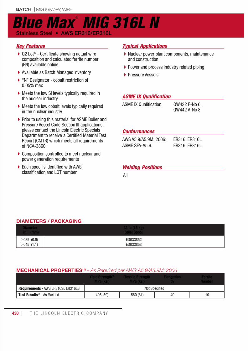
7/18/2019 c110 - Lincoln Electric Consumables 2014
http://slidepdf.com/reader/full/c110-lincoln-electric-consumables-2014 430/511430 ı T H E L I N C O L N E L E C T R I C C O M P A N Y
Q2 Lot® - Certificate showing actual wire
composition and calculated ferrite number(FN) available online
Available as Batch Managed Inventory
“N” Designator - cobalt restriction of0.05% max
Meets the low Si levels typically required inthe nuclear industry
Meets the low cobalt levels typically requiredin the nuclear industry.
Prior to using this material for ASME Boiler andPressure Vessel Code Section III applications,please contact the Lincoln Electric SpecialsDepartment to receive a Certified Material TestReport (CMTR) which meets all requirementsof NCA-3860
Composition controlled to meet nuclear andpower generation requirements
Each spool is identified with AWSclassification and LOT number
Key Features
Welding Positions
Typical Applications
All
Nuclear power plant components, maintenance
and construction Power and process industry related piping
Pressure Vessels
Conformances
ASME IX Qualification: QW432 F-No 6,QW442 A-No 8
ASME IX Qualification
Blue Max ®
MIG 316L N Stainless Steel • AWS ER316/ER316L
DIAMETERS / PACKAGING
Diameter 33 lb (15 kg)Steel Spoolin (mm)
0.0350.045
(0.9)(1.1)
ED033852ED033853
AWS A5.9/A5.9M: 2006:
ASME SFA-A5.9:
ER316, ER316L
ER316, ER316L
MECHANICAL PROPERTIES(1) – As Required per AWS A5.9/A5.9M: 2006
Yield Strength(2)
MPa (ksi)Tensile Strength
MPa (ksi)Elongation
%Ferrite
Number
Requirements - AWS ER316Si, ER316LSi Not Specified
Test Results(3) - As-Welded 405 (59) 560 (81) 40 10
BATCH | MIG (GMAW) WIRE
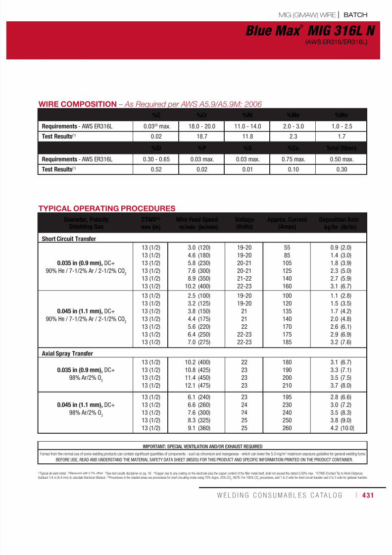
7/18/2019 c110 - Lincoln Electric Consumables 2014
http://slidepdf.com/reader/full/c110-lincoln-electric-consumables-2014 431/511W E L D I N G C O N S U M A B L E S C A TA L O G ı 431
Blue Max ®
MIG 316L N(AWS ER316/ER316L)
(1)
Typical all weld metal.(2)
Measured with 0.2% offset.(3)
See test results disclaimer on pg. 18.(4)
Copper due to any coating on the electrode plus the copper content of the filler metal itself, shall not exceed the stated 0.50% max.(5)
CTWD (Contact Tip to Work Distance).Subtract 1/4 in (6.4 mm) to calculate Electrical Stickout. (6)Procedures in the shaded areas are procedures for short circuiting mode using 75% Argon, 25% CO2. NOTE: For 100% CO
2 procedures, add 1 to 2 volts for short circuit transfer and 2 to 3 volts for globular transfer.
IMPORTANT: SPECIAL VENTILATION AND/OR EXHAUST REQUIRED
Fumes from the normal use of some welding products can contain significant quantities of components - such as chromium and manganese - which can lower the 5.0 mg/m3 maximum exposure guideline for general welding fume.
BEFORE USE, READ AND UNDERSTAND THE MATERIAL SAFETY DATA SHEET (MSDS) FOR THIS PRODUCT AND SPECIFIC INFORMATION PRINTED ON THE PRODUCT CONTAINER.
TYPICAL OPERATING PROCEDURES
Diameter, PolarityShielding Gas
CTWD(5) Wire Feed Speed Voltage(Volts)
Approx. Current(Amps)
Deposition Ratemm (in) m/min (in/min) kg/hr (lb/hr)
Short Circuit Transfer
0.035 in (0.9 mm), DC+
90% He / 7-1/2% Ar / 2-1/2% CO2
13 (1/2)
13 (1/2)
13 (1/2)
13 (1/2)
13 (1/2)
13 (1/2)
3.0
4.6
5.8
7.6
8.9
10.2
(120)
(180)
(230)
(300)
(350)
(400)
19-20
19-20
20-21
20-21
21-22
22-23
55
85
105
125
140
160
0.9
1.4
1.8
2.3
2.7
3.1
(2.0)
(3.0)
(3.9)
(5.0)
(5.9)
(6.7)
0.045 in (1.1 mm), DC+
90% He / 7-1/2% Ar / 2-1/2% CO2
13 (1/2)
13 (1/2)
13 (1/2)
13 (1/2)
13 (1/2)
13 (1/2)
13 (1/2)
2.5
3.2
3.8
4.4
5.6
6.4
7.0
(100)
(125)
(150)
(175)
(220)
(250)
(275)
19-20
19-20
21
21
22
22-23
22-23
100
120
135
140
170
175
185
1.1
1.5
1.7
2.0
2.6
2.9
3.2
(2.8)
(3.5)
(4.2)
(4.8)
(6.1)
(6.9)
(7.6)
Axial Spray Transfer
0.035 in (0.9 mm), DC+
98% Ar/2% O2
13 (1/2)
13 (1/2)
13 (1/2)13 (1/2)
10.2
10.8
11.412.1
(400)
(425)
(450)(475)
22
23
2323
180
190
200210
3.1
3.3
3.53.7
(6.7)
(7.1)
(7.5)(8.0)
0.045 in (1.1 mm), DC+
98% Ar/2% O2
13 (1/2)
13 (1/2)
13 (1/2)
13 (1/2)
13 (1/2)
6.1
6.6
7.6
8.3
9.1
(240)
(260)
(300)
(325)
(360)
23
24
24
25
25
195
230
240
250
260
2.8
3.0
3.5
3.8
4.2
(6.6)
(7.2)
(8.3)
(9.0)
(10.0)
MIG (GMAW) WIRE | BATCH
WIRE COMPOSITION – As Required per AWS A5.9/A5.9M: 2006
%C %Cr %Ni %Mo %Mn
Requirements - AWS ER316L 0.03(2) max. 18.0 - 20.0 11.0 - 14.0 2.0 - 3.0 1.0 - 2.5
Test Results(1) 0.02 18.7 11.8 2.3 1.7
%Si %P %S %Cu Total Others
Requirements - AWS ER316L 0.30 - 0.65 0.03 max. 0.03 max. 0.75 max. 0.50 max.
Test Results(1) 0.52 0.02 0.01 0.10 0.30

7/18/2019 c110 - Lincoln Electric Consumables 2014
http://slidepdf.com/reader/full/c110-lincoln-electric-consumables-2014 432/511432 ı T H E L I N C O L N E L E C T R I C C O M P A N Y
DIAMETERS / PACKAGING
Diameter 33 lb (15 kg)Plastic Spoolin (mm)
0.0350.045
(0.9)(1.2)
ED033955ED033956
(1)
Typical all weld metal.(2)
Measured with 0.2% offset.(3)
See test results disclaimer on pg. 18.(4)
Copper due to any coating on the electrode plus the copper content of the filler metal itself, shall not exceed the stated 0.50% max.(5)
CTWD (Contact Tip to Work Distance).Subtract 1/4 in (6.4 mm) to calculate Electrical Stickout. (6)Procedures in the shaded areas are procedures for short circuiting mode using 75% Argon, 25% CO2. NOTE: For 100% CO
2 procedures, add 1 to 2 volts for short circuit transfer and 2 to 3 volts for globular transfer.
IMPORTANT: SPECIAL VENTILATION AND/OR EXHAUST REQUIRED
Fumes from the normal use of some welding products can contain significant quantities of components - such as chromium and manganese - which can lower the 5.0 mg/m3 maximum exposure guideline for general welding fume.
BEFORE USE, READ AND UNDERSTAND THE MATERIAL SAFETY DATA SHEET (MSDS) FOR THIS PRODUCT AND SPECIFIC INFORMATION PRINTED ON THE PRODUCT CONTAINER.
WIRE COMPOSITION(1) – As Required per AWS Similar to AWS A5.9/A5.9M: 2006
%C %Cr %Ni %Mo %MnRequirements - AWS ER2209 0.030 max. 21.5-23.5 7.5-9.5 2.5-3.5 0.5-2.0
Test Results(3) 0.018 22.7 8.5 3.0 1.5
%Si %P %S %Cu %NRequirements - AWS ER2209 0.90 max. 0.03 max. 0.03 max. 0.75 max. 0.08-0.20
Test Results(3) 0.45 0.03 0.03 0.30 0.15
MECHANICAL PROPERTIES(1) – As Required per AWS A5.9-93
Yield Strength(2)
MPa (ksi)Tensile Strength
MPa (ksi)Elongation
%
Charpy V-NotchJ (ft•lbf)
@ -40°C (-40°F)
Requirements - AWS ER2209 Not Specified
Test Results(3)
As-Welded with 98% Ar / 2% CO2 625 (91) 810 (118) 28 105 (78)
Q2 Lot® - Certificate showing actual wire
composition and calculated ferrite number(FN) available online
Available as Batch Managed Inventory
“N” Designator - cobalt restriction of0.05% max
Premium performance and quality
Designed for joining duplex stainless steels
Provides high resistance to general corrosion,pitting and stress corrosion
Composition is controlled to produceconsistent mechanical properties
Prior to using this material for ASME Boiler andPressure Vessel Code Section III applications,please contact the Lincoln Electric SpecialsDepartment to receive a Certified Material TestReport (CMTR) which meet all requirements ofNCA-3860.
Key Features Welding Positions
Typical Applications
All
Nuclear power plant construction and maintenance
Alloy 2205: UNS S31803, UNS S31500
Alloy 2304: UNS S32304, UNS S31200
Air pollution control systems for coal fired power plants
Power and process industry components and piping
Pressure Vessels
Conformances
ASME IX Qualification: QW432 F-No 6,QW442 A-No 8
ASME IX Qualification
Blue Max ®
LNM 4462 N Stainless Steel • AWS ER2209
AWS A5.9-93:
ASME SFA-A5.9:
ER2209
ER2209
BATCH | MIG (GMAW) WIRE
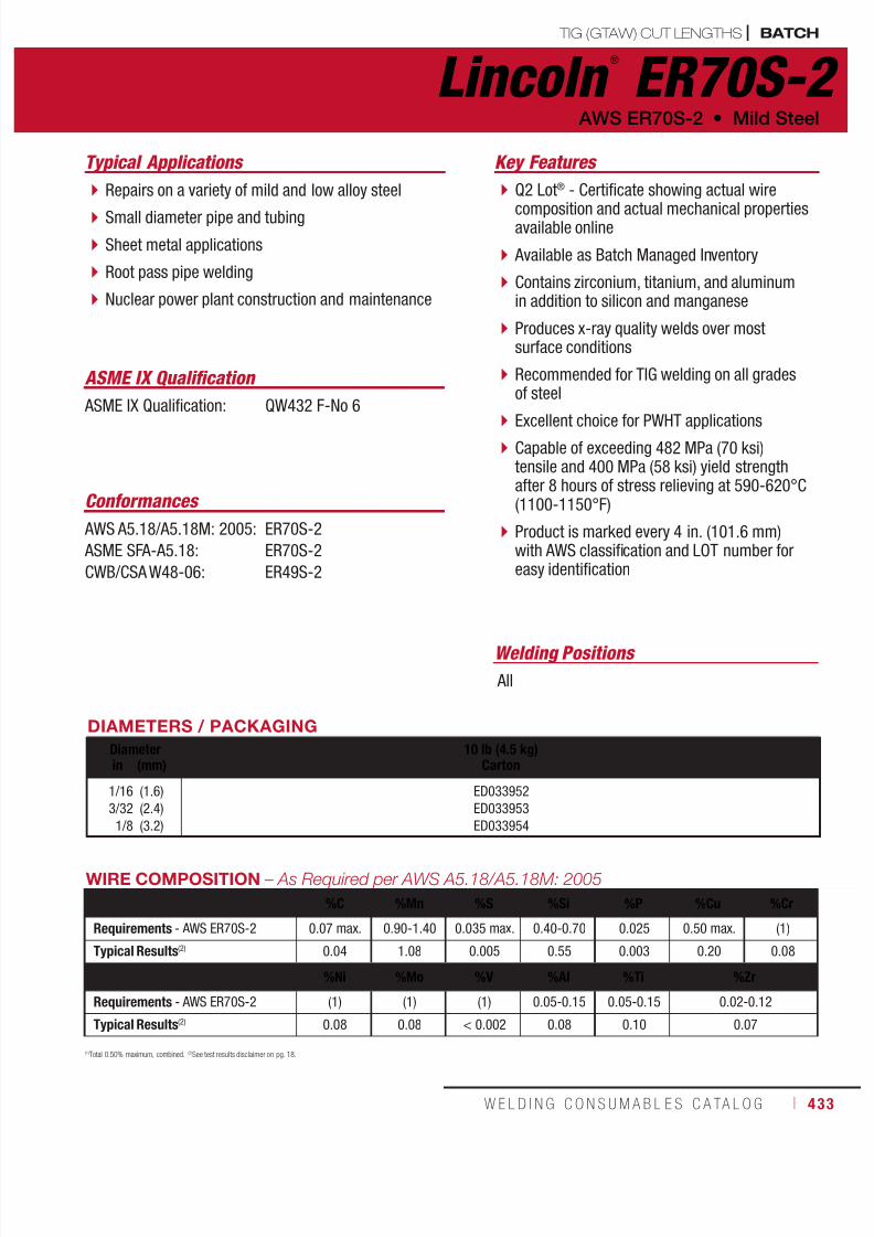
7/18/2019 c110 - Lincoln Electric Consumables 2014
http://slidepdf.com/reader/full/c110-lincoln-electric-consumables-2014 433/511W E L D I N G C O N S U M A B L E S C A TA L O G ı 433
TIG (GTAW) CUT LENGTHS | BATCH
Q2 Lot® - Certificate showing actual wire
composition and actual mechanical propertiesavailable online
Available as Batch Managed Inventory
Contains zirconium, titanium, and aluminumin addition to silicon and manganese
Produces x-ray quality welds over mostsurface conditions
Recommended for TIG welding on all gradesof steel
Excellent choice for PWHT applications Capable of exceeding 482 MPa (70 ksi)tensile and 400 MPa (58 ksi) yield strengthafter 8 hours of stress relieving at 590-620°C(1100-1150°F)
Product is marked every 4 in. (101.6 mm)with AWS classification and LOT number foreasy identification
Key Features
Welding Positions
Typical Applications
All
Repairs on a variety of mild and low alloy steel
Small diameter pipe and tubing
Sheet metal applications
Root pass pipe welding
Nuclear power plant construction and maintenance
Conformances
ASME IX Qualification: QW432 F-No 6
ASME IX Qualification
Lincoln ®
ER70S-2 AWS ER70S-2 • Mild Steel
DIAMETERS / PACKAGING
Diameter 10 lb (4.5 kg)Cartonin (mm)
1/16
3/32
1/8
(1.6)
(2.4)
(3.2)
ED033952
ED033953
ED033954
AWS A5.18/A5.18M: 2005:
ASME SFA-A5.18:
CWB/CSA W48-06:
ER70S-2
ER70S-2
ER49S-2
WIRE COMPOSITION – As Required per AWS A5.18/A5.18M: 2005
%C %Mn %S %Si %P %Cu %Cr
Requirements - AWS ER70S-2 0.07 max. 0.90-1.40 0.035 max. 0.40-0.70 0.025 0.50 max. (1)
Typical Results(2) 0.04 1.08 0.005 0.55 0.003 0.20 0.08
%Ni %Mo %V %Al %Ti %Zr
Requirements - AWS ER70S-2 (1) (1) (1) 0.05-0.15 0.05-0.15 0.02-0.12
Typical Results(2) 0.08 0.08 < 0.002 0.08 0.10 0.07
(1)
Total 0.50% maximum, combined.(2)
See test results disclaimer on pg. 18.
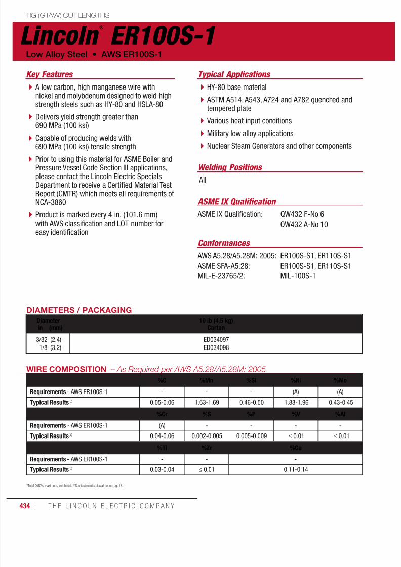
7/18/2019 c110 - Lincoln Electric Consumables 2014
http://slidepdf.com/reader/full/c110-lincoln-electric-consumables-2014 434/511434 ı T H E L I N C O L N E L E C T R I C C O M P A N Y
TIG (GTAW) CUT LENGTHS
A low carbon, high manganese wire with
nickel and molybdenum designed to weld highstrength steels such as HY-80 and HSLA-80
Delivers yield strength greater than690 MPa (100 ksi)
Capable of producing welds with690 MPa (100 ksi) tensile strength
Prior to using this material for ASME Boiler andPressure Vessel Code Section III applications,please contact the Lincoln Electric SpecialsDepartment to receive a Certified Material Test
Report (CMTR) which meets all requirements ofNCA-3860
Product is marked every 4 in. (101.6 mm)with AWS classification and LOT number foreasy identification
Key Features
Welding Positions
Typical Applications
All
HY-80 base material
ASTM A514, A543, A724 and A782 quenched andtempered plate
Various heat input conditions
Military low alloy applications
Nuclear Steam Generators and other components
Conformances
ASME IX Qualification: QW432 F-No 6
QW432 A-No 10
ASME IX Qualification
Lincoln ®
ER100S-1Low Alloy Steel • AWS ER100S-1
DIAMETERS / PACKAGING
Diameter 10 lb (4.5 kg)Cartonin (mm)
3/32
1/8
(2.4)
(3.2)
ED034097
ED034098
AWS A5.28/A5.28M: 2005:
ASME SFA-A5.28:
MIL-E-23765/2:
ER100S-S1, ER110S-S1
ER100S-S1, ER110S-S1
MIL-100S-1
(1)Total 0.50% maximum, combined. (2)See test results disclaimer on pg. 18.
WIRE COMPOSITION – As Required per AWS A5.28/A5.28M: 2005
%C %Mn %Si %Ni %Mo
Requirements - AWS ER100S-1 - - - (A) (A)
Typical Results(3) 0.05-0.06 1.63-1.69 0.46-0.50 1.88-1.96 0.43-0.45
%Cr %S %P %V %Al
Requirements - AWS ER100S-1 (A) - - - -
Typical Results(3) 0.04-0.06 0.002-0.005 0.005-0.009 ≤ 0.01 ≤ 0.01
%Ti %Zr %Cu
Requirements - AWS ER100S-1 - - -
Typical Results(3) 0.03-0.04 ≤ 0.01 0.11-0.14
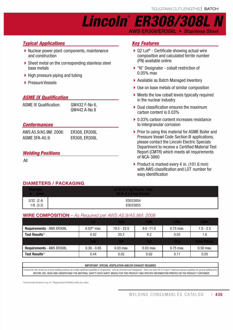
7/18/2019 c110 - Lincoln Electric Consumables 2014
http://slidepdf.com/reader/full/c110-lincoln-electric-consumables-2014 435/511W E L D I N G C O N S U M A B L E S C A TA L O G ı 435
Q2 Lot® - Certificate showing actual wire
composition and calculated ferrite number(FN) available online
“N” Designator - cobalt restriction of0.05% max
Available as Batch Managed Inventory
Use on base metals of similar composition
Meets the low cobalt levels typically requiredin the nuclear industry
Dual classification ensures the maximum
carbon content is 0.03% 0.03% carbon content increases resistanceto intergranular corrosion
Prior to using this material for ASME Boiler andPressure Vessel Code Section III applications,please contact the Lincoln Electric SpecialsDepartment to receive a Certified Material TestReport (CMTR) which meets all requirementsof NCA-3860
Product is marked every 4 in. (101.6 mm)
with AWS classification and LOT number foreasy identification
Key Features
Welding Positions
Typical Applications
All
Nuclear power plant components, maintenance
and construction Sheet metal on the corresponding stainless steelbase metals
High pressure piping and tubing
Pressure Vessels
Conformances
ASME IX Qualification: QW432 F-No 6,QW442 A-No 8
ASME IX Qualification
Lincoln ®
ER308/308L N AWS ER308/ER308L • Stainless Steel
DIAMETERS / PACKAGING
Diameter 10 lb (4.5 kg) Plastic Tube30 lb (13.6 kg) Masterin (mm)
3/32
1/8
(2.4)
(3.2)
ED033854
ED033855
AWS A5.9/A5.9M: 2006:
ASME SFA-A5.9:
ER308, ER308L
ER308, ER308L
WIRE COMPOSITION – As Required per AWS A5.9/A5.9M: 2006
%C %Cr %Ni %Mo %Mn
Requirements - AWS ER308L 0.03(2) max. 19.5 - 22.0 9.0 -11.0 0.75 max. 1.0 - 2.5
Test Results(1) 0.02 20.2 9.2 0.03 1.6
%Si %P %S %Cu Total Others
Requirements - AWS ER308L 0.30 - 0.65 0.03 max. 0.03 max. 0.75 max. 0.50 max.
Test Results(1) 0.44 0.02 0.02 0.11 0.03
(1)See test results disclaimer on pg. 18. (2)Requirements for ER308 is 0.08% max. carbon.
IMPORTANT: SPECIAL VENTILATION AND/OR EXHAUST REQUIRED
Fumes from the normal use of some welding products can contain significant quantities of components - such as chromium and manganese - which can lower the 5.0 mg/m3 maximum exposure guideline for general welding fume.
BEFORE USE, READ AND UNDERSTAND THE MATERIAL SAFETY DATA SHEET (MSDS) FOR THIS PRODUCT AND SPECIFIC INFORMATION PRINTED ON THE PRODUCT CONTAINER.
TIG (GTAW) CUT LENGTHS | BATCH

7/18/2019 c110 - Lincoln Electric Consumables 2014
http://slidepdf.com/reader/full/c110-lincoln-electric-consumables-2014 436/511436 ı T H E L I N C O L N E L E C T R I C C O M P A N Y
Q2 Lot® - Certificate showing actual wire
composition and calculated ferrite number(FN) available online
Available as Batch Managed Inventory
“N” Designator - cobalt restriction of0.05% max
Use for welding dissimilar alloys in wroughtor cast form
Meets the low cobalt levels typically required inthe nuclear industry
Occasionally used for welding “18-8” basemetals when severe corrosion conditionsexist or dissimilar metals
0.03% carbon content increases resistanceto intergranular corrosion
Prior to using this material for ASME Boiler andPressure Vessel Code Section III applications,please contact the Lincoln Electric SpecialsDepartment to receive a Certified Material TestReport (CMTR) which meets all requirements
of NCA-3860 Product is marked every 4 in. (101.6 mm)with AWS classification and LOT number foreasy identification
Key Features
Welding Positions
Typical Applications
All
Nuclear power plant components, maintenance
and construction Sheet metal on the corresponding stainlesssteel base metals
High pressure piping and tubing
Pressure Vessels
Conformances
ASME IX Qualification: QW432 F-No 6,QW442 A-No 8
ASME IX Qualification
Lincoln ®
ER309/309L N Stainless Steel • AWS ER309/ER309L
DIAMETERS / PACKAGING
Diameter 10 lb (4.5 kg) Plastic Tube30 lb (13.6 kg) Masterin (mm)
3/32
1/8
(2.4)
(3.2)
ED033856
ED033857
AWS A5.9/A5.9M: 2006:
ASME SFA-A5.9:
ER309, ER309L
ER309, ER309L
WIRE COMPOSITION – As Required per AWS A5.9/A5.9M: 2006%C %Cr %Ni %Mo %Mn
Requirements - AWS ER309L 0.03(2) max. 23.0 - 25.0 12.0 - 14.0 0.75 max. 1.0 - 2.5
Test Results(1) 0.02 23.7 13.9 0.04 1.8
%Si %P %S %Cu Total OthersRequirements - AWS ER309L 0.30 - 0.65 0.03 max. 0.03 max. 0.75 max. 0.50 max.
Test Results(1) 0.51 0.02 0.01 0.05 0.06
(1)See test results disclaimer on pg. 18. (2)Requirements for ER309 is 0.12% max. carbon.
IMPORTANT: SPECIAL VENTILATION AND/OR EXHAUST REQUIRED
Fumes from the normal use of some welding products can contain significant quantities of components - such as chromium and manganese - which can lower the 5.0 mg/m3 maximum exposure guideline for general welding fume.
BEFORE USE, READ AND UNDERSTAND THE MATERIAL SAFETY DATA SHEET (MSDS) FOR THIS PRODUCT AND SPECIFIC INFORMATION PRINTED ON THE PRODUCT CONTAINER.
BATCH | TIG (GTAW) CUT LENGTHS

7/18/2019 c110 - Lincoln Electric Consumables 2014
http://slidepdf.com/reader/full/c110-lincoln-electric-consumables-2014 437/511W E L D I N G C O N S U M A B L E S C A TA L O G ı 437
Q2 Lot® - Certificate showing actual wire
composition and calculated ferrite number(FN) available online
Available as Batch Managed Inventory
“N” Designator - cobalt restriction of0.05% max
Premium performance and quality
Designed for joining duplex stainless steels,such as type 2205, for applications withservice temperatures up to 250°C (480°F) anddown to -40°C (-40°F).
Provides high resistance to general corrosion,pitting and stress corrosion
Composition is controlled to produce consistentmechanical properties
Key Features
Welding Positions
Typical Applications
All
Nuclear power plant construction and maintenance
Alloy 2205: UNS S31803, UNS S31500
Alloy 2304: UNS S32304, UNS S31200
Air pollution control systems for coal fired power plants
Power and process industry components and piping
Pressure Vessels
Conformances
Blue Max ®
LNT 4462 N AWS ER2209 • Stainless Steel
DIAMETERS / PACKAGING
Diameter 10 lb (4.5 kg) Plastic Tube
30 lb (13.6 kg) Masterin (mm)3/32
1/8
(2.4)
(3.2)
ED033957
ED033958
AWS A5.9/A5.9M: 2006:
ASME SFA-A5.9:
ER2209
ER2209
(1)Typical all weld metal. (2)Measured with 0.2% offset. (3)See test results disclaimer on pg. 18.
MECHANICAL PROPERTIES(1) – As Required per AWS A5.9/A5.9M: 2006
Yield Strength(2)
Tensile Strength
Elongation
Charpy V-NotchJ (ft•lbf)
MPa (ksi) MPa (ksi) % @ -20°C (-4°F) @ -60°C (-75°F)
Requirements - AWS ER2209 Not Specified
Test Results(2) - As-Welded 600 (87) 800 (116) 28 60 (44) 45 (33)
IMPORTANT: SPECIAL VENTILATION AND/OR EXHAUST REQUIRED
Fumes from the normal use of some welding products can contain significant quantities of components - such as chromium and manganese - which can lower the 5.0 mg/m3 maximum exposure guideline for general welding fume.
BEFORE USE, READ AND UNDERSTAND THE MATERIAL SAFETY DATA SHEET (MSDS) FOR THIS PRODUCT AND SPECIFIC INFORMATION PRINTED ON THE PRODUCT CONTAINER.
WIRE COMPOSITION(1)
– As Required per AWS A5.9/A5.9M: 2006%C %Cr %Ni %Mo %Mn
Requirements - AWS ER2209 0.030 max. 21.5-23.5 7.5-9.5 2.5-3.5 0.5-2.0
Test Results(3) 0.018 22.7 8.5 3.0 1.5
%Si %P %S %Cu %N
Requirements - AWS ER2209 0.90 max. 0.03 max. 0.03 max. 0.75 max. 0.08-0.20
Test Results(3) 0.50 0.03 0.03 0.30 0.15
ASME IX Qualification: QW432 F-No 6,QW442 A-No 8
ASME IX Qualification
TIG (GTAW) CUT LENGTHS | BATCH

7/18/2019 c110 - Lincoln Electric Consumables 2014
http://slidepdf.com/reader/full/c110-lincoln-electric-consumables-2014 438/511438 ı T H E L I N C O L N E L E C T R I C C O M P A N Y
Q2 Lot® - Certificate showing actual wire
composition available online Available as Batch Managed Inventory
“N” Designator - design modified tomeet properties after stress relief
A PLW product which has been treated tominimize weld defects that can be seen inthe use of MIG wires for the automaticTIG process.
Provides a consistent and exceptionallystable arc for automatic TIG welding
High levels of manganese and silicondeoxidizers tolerate medium to heavy millscale surfaces
Excellent toe-wetting provides optimal beadappearance
Each spool is identified with AWS classificationand LOT number
Key Features
BATCH | ORBITAL TIG (GTAW) WIRE
Welding Positions
Typical Applications
All
Nuclear power plant construction and maintenance
Power and process industry related piping
Medium to heavy mill scale base material
Robotic or hard automation
Conformances
ASME IX Qualification: QW432 F-No 6,QW442 A-No 1
ASME IX Qualification
SuperArc ®
Orbital TIG L-56 ®
NMild Steel • AWS ER70S-6
DIAMETERS / PACKAGING
Diameter 2 lb (1 kg) Plastic Spool8 lb (3.6 kg) Master Carton
10 lb (4.5 kg)Plastic Spoolin (mm)
0.035 (0.9) ED033840 ED033841
AWS A5.18/A5.18M: 2005:
ASME SFA-A5.18:
ER70S-6
ER70S-6
(1)Typical all weld metal. (2)Measured with 0.2% offset. (3)See test results disclaimer on pg. 18. (4)Copper due to any coating on the electrode plus the copper content of the filler metal itself, shall not exceed the stated 0.50% max. (5)CTWD (Contact Tip to WorkDistance). Subtract 1/4 in (6.4 mm) to calculate Electrical Stickout. (6)Procedures in these areas are procedures for short circuiting mode using 100% CO
2. When using 75% Argon, 25% CO
2 for short circuit transfer, reduce voltage by 1 to 2 volts.
WIRE COMPOSITION – As Required per AWS A5.18/A5.18M: 2005
%C %Mn %Si %S %P
Requirements - AWS ER70S-6 0.06-0.15 1.40-1.85 0.80-1.15 0.035 max. 0.025 max.
Typical Results(3) 0.08-0.09 1.42-1.60 0.81-0.87 0.006-0.010 0.004-0.010
%Cr %Ni %Mo %V %Cu (Total)(4)
Requirements - AWS ER70S-6 0.15 max. 0.15 max. 0.15 max. 0.03 max. 0.50 max.
Typical Results(3) 0.01-0.05 ≤ 0.04 ≤ 0.01 < 0.01 0.17-0.22

7/18/2019 c110 - Lincoln Electric Consumables 2014
http://slidepdf.com/reader/full/c110-lincoln-electric-consumables-2014 439/511W E L D I N G C O N S U M A B L E S C A TA L O G ı 439
Q2 Lot® - Certificate showing actual wire
composition available online Available as Batch Managed Inventory
“N” Designator - design modified tomeet properties after stress relief
A PLW product which has been treated tominimize weld defects that can be seen inthe use of MIG wires for the automaticTIG process
Provides a consistent and exceptionallystable arc for automatic TIG welding
Contains zirconium, titanium, and aluminumin addition to silicon and manganese
Produces x-ray quality welds over mostsurface conditions
Recommended for TIG welding on all gradesof steel
Excellent choice for PWHT applications
Each spool is identified with AWS classificationand LOT number
Key Features
ORBITAL TIG (GTAW) WIRE | BATCH
Welding Positions
Typical Applications
All
Nuclear power plant construction and maintenance
Power and process industry related piping
Medium to heavy mill scale base material
Robotic or hard automation
Conformances
ASME IX Qualification: QW432 F-No 6,QW442 A-No 1
ASME IX Qualification
SuperArc ®
Orbital TIG L-52 N AWS ER70S-2 • Mild Steel
DIAMETERS / PACKAGING
Diameter 2 lb (1 kg) Plastic Spool8 lb (3.6 kg) Master Carton
10 lb (4.5 kg)Plastic Spoolin (mm)
0.035 (0.9) ED033947 ED033948
(1)
Typical all weld metal.(2)
Measured with 0.2% offset.(3)
See test results disclaimer on pg. 18.(4)
Copper due to any coating on the electrode plus the copper content of the filler metal itself, shall not exceed the stated 0.50% max.(5)
CTWD (Contact Tip to Work Distance).Subtract 1/4 in (6.4 mm) to calculate Electrical Stickout. (6)Procedures in the shaded areas are procedures for short circuiting mode using 75% Argon, 25% CO2. NOTE: For 100% CO
2 procedures, add 1 to 2 volts for short circuit transfer and 2 to 3 volts for globular transfer.
AWS A5.18/A5.18M: 2005:
ASME SFA-A5.18:
ER70S-2
ER70S-2
WIRE COMPOSITION – As Required per AWS A5.18/A5.18M: 2005
%C %Mn %S %Si %P %Cu %Cr
Requirements - AWS ER70S-2 0.07 max. 0.90-1.40 0.035 max. 0.40-0.70 0.0025 max. 0.50 max. (1)
Typical Results(2) 0.04 1.08 0.005 0.55 0.0003 0.20 0.08
%Ni %Mo %V %Al %Ti %Zr
Requirements - AWS ER70S-2 (1) (1) (1) 0.05-0.15 0.05-0.15 0.02-0.12
Typical Results(2) 0.08 0.08 < 0.002 0.08 0.10 0.07
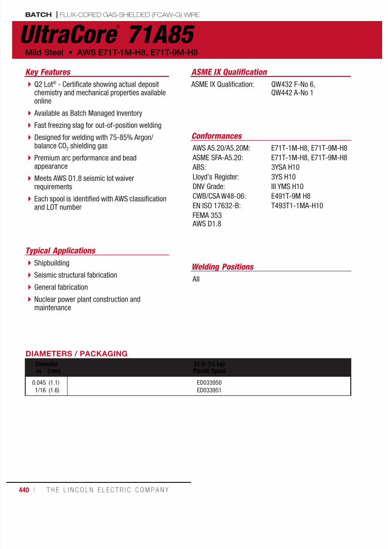
7/18/2019 c110 - Lincoln Electric Consumables 2014
http://slidepdf.com/reader/full/c110-lincoln-electric-consumables-2014 440/511440 ı T H E L I N C O L N E L E C T R I C C O M P A N Y
Key Features
Welding Positions
Typical Applications
All
Shipbuilding
Seismic structural fabrication
General fabrication
Nuclear power plant construction andmaintenance
Conformances
ASME IX Qualification: QW432 F-No 6,
QW442 A-No 1
ASME IX Qualification
UltraCore ®
71A85 Mild Steel • AWS E71T-1M-H8, E71T-9M-H8
DIAMETERS / PACKAGING
Diameter 33 lb (15 kg)Plastic Spoolin (mm)
0.045
1/16
(1.1)
(1.6)
ED033950
ED033951
AWS A5.20/A5.20M:
ASME SFA-A5.20:
ABS:
Lloyd’s Register:
DNV Grade:CWB/CSA W48-06:
EN ISO 17632-B:
FEMA 353 AWS D1.8
E71T-1M-H8, E71T-9M-H8
E71T-1M-H8, E71T-9M-H8
3YSA H10
3YS H10
III YMS H10E491T-9M H8
T493T1-1MA-H10
Q2 Lot® - Certificate showing actual deposit
chemistry and mechanical properties availableonline
Available as Batch Managed Inventory
Fast freezing slag for out-of-position welding
Designed for welding with 75-85% Argon/balance CO2 shielding gas
Premium arc performance and beadappearance
Meets AWS D1.8 seismic lot waiver
requirements Each spool is identified with AWS classificationand LOT number
BATCH | FLUX-CORED GAS-SHIELDED (FCAW-G) WIRE
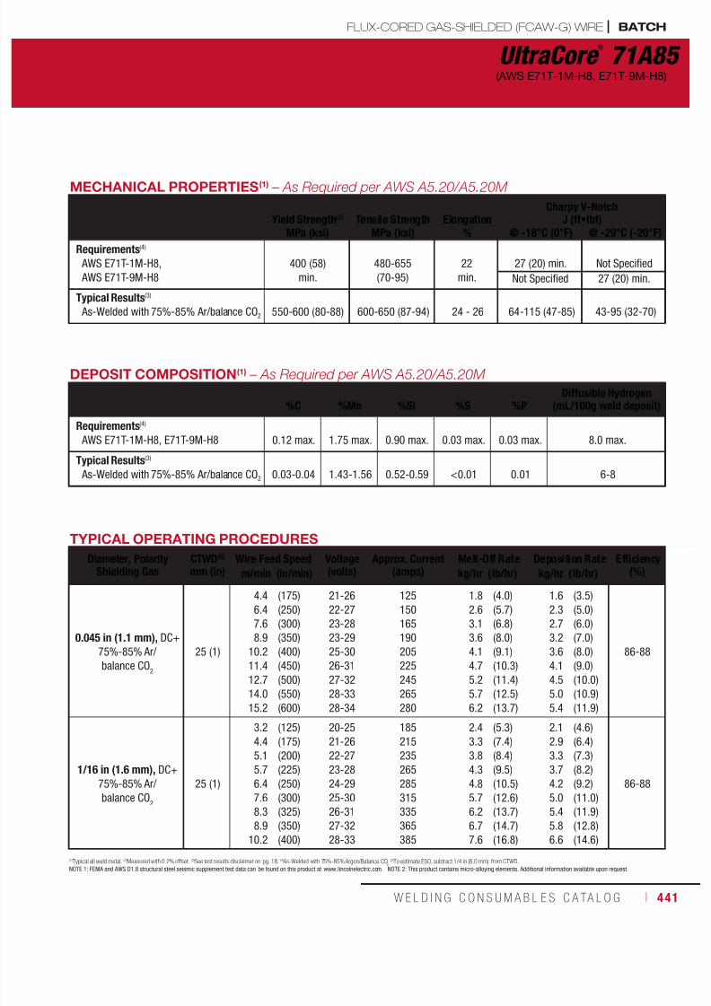
7/18/2019 c110 - Lincoln Electric Consumables 2014
http://slidepdf.com/reader/full/c110-lincoln-electric-consumables-2014 441/511W E L D I N G C O N S U M A B L E S C A TA L O G ı 441
MECHANICAL PROPERTIES(1) – As Required per AWS A5.20/A5.20M
Yield Strength(2) Tensile Strength ElongationCharpy V-Notch
J (ft•lbf)MPa (ksi) MPa (ksi) % @ -18°C (0°F) @ -29°C (-20°F)
Requirements(4)
AWS E71T-1M-H8,
AWS E71T-9M-H8
400 (58)
min.
480-655
(70-95)
22
min.
27 (20) min. Not Specified
Not Specified 27 (20) min.
Typical Results(3)
As-Welded with 75%-85% Ar/balance CO2 550-600 (80-88) 600-650 (87-94) 24 - 26 64-115 (47-85) 43-95 (32-70)
UltraCore ®
71A85(AWS E71T-1M-H8, E71T-9M-H8)
DEPOSIT COMPOSITION(1) – As Required per AWS A5.20/A5.20M
%C
%Mn
%Si
%S
%P
Diffusible Hydrogen(mL/100g weld deposit)
Requirements(4)
AWS E71T-1M-H8, E71T-9M-H8 0.12 max. 1.75 max. 0.90 max. 0.03 max. 0.03 max. 8.0 max.
Typical Results(3)
As-Welded with 75%-85% Ar/balance CO2 0.03-0.04 1.43-1.56 0.52-0.59 <0.01 0.01 6-8
TYPICAL OPERATING PROCEDURES
Diameter, PolarityShielding Gas
CTWD(5)
mm (in)Wire Feed Speed Voltage
(volts)Approx. Current
(amps)Melt-Off Rate Deposition Rate Efficiency
(%)m/min (in/min) kg/hr (lb/hr) kg/hr (lb/hr)
0.045 in (1.1 mm), DC+
75%-85% Ar/
balance CO2
25 (1)
4.4
6.4
7.6
8.9
10.2
11.4
12.7
14.0
15.2
(175)
(250)
(300)
(350)
(400)
(450)
(500)
(550)
(600)
21-26
22-27
23-28
23-29
25-30
26-31
27-32
28-33
28-34
125
150
165
190
205
225
245
265
280
1.8
2.6
3.1
3.6
4.1
4.7
5.2
5.7
6.2
(4.0)
(5.7)
(6.8)
(8.0)
(9.1)
(10.3)
(11.4)
(12.5)
(13.7)
1.6
2.3
2.7
3.2
3.6
4.1
4.5
5.0
5.4
(3.5)
(5.0)
(6.0)
(7.0)
(8.0)
(9.0)
(10.0)
(10.9)
(11.9)
86-88
1/16 in (1.6 mm), DC+
75%-85% Ar/
balance CO2
25 (1)
3.2
4.4
5.1
5.7
6.4
7.6
8.3
8.9
10.2
(125)
(175)
(200)
(225)
(250)
(300)
(325)
(350)
(400)
20-25
21-26
22-27
23-28
24-29
25-30
26-31
27-32
28-33
185
215
235
265
285
315
335
365
385
2.4
3.3
3.8
4.3
4.8
5.7
6.2
6.7
7.6
(5.3)
(7.4)
(8.4)
(9.5)
(10.5)
(12.6)
(13.7)
(14.7)
(16.8)
2.1
2.9
3.3
3.7
4.2
5.0
5.4
5.8
6.6
(4.6)
(6.4)
(7.3)
(8.2)
(9.2)
(11.0)
(11.9)
(12.8)
(14.6)
86-88
(1)Typical all weld metal. (2)Measured with 0.2% offset. (3)See test results disclaimer on pg. 18. (4) As-Welded with 75%-85% Argon/Balance CO2(5)To estimate ESO, subtract 1/4 in (6.0 mm) from CTWD.
NOTE 1: FEMA and AWS D1.8 structural steel seismic supplement test data can be found on this product at www.lincolnelectric.com. NOTE 2: This product contains micro-alloying elements. Additional information available upon request.
FLUX-CORED GAS-SHIELDED (FCAW-G) WIRE | BATCH
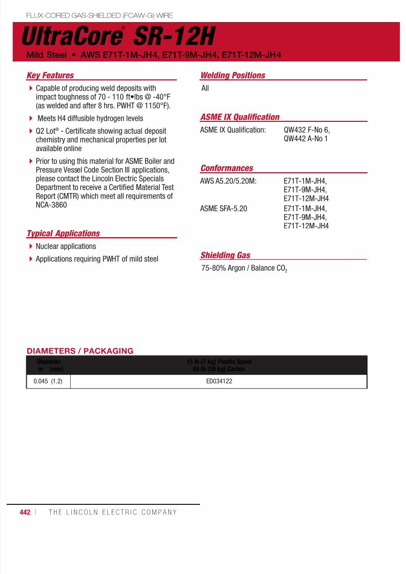
7/18/2019 c110 - Lincoln Electric Consumables 2014
http://slidepdf.com/reader/full/c110-lincoln-electric-consumables-2014 442/511442 ı T H E L I N C O L N E L E C T R I C C O M P A N Y
DIAMETERS / PACKAGING
Diameter 15 lb (7 kg) Plastic Spool60 lb (28 kg) Cartonin (mm)
0.045 (1.2) ED034122
Capable of producing weld deposits with
impact toughness of 70 - 110 ft•lbs @ -40°F(as welded and after 8 hrs. PWHT @ 1150°F).
Meets H4 diffusible hydrogen levels
Q2 Lot® - Certificate showing actual depositchemistry and mechanical properties per lotavailable online
Prior to using this material for ASME Boiler andPressure Vessel Code Section III applications,please contact the Lincoln Electric SpecialsDepartment to receive a Certified Material Test
Report (CMTR) which meet all requirements ofNCA-3860
Key Features Welding Positions
Shielding Gas
Typical Applications
All
75-80% Argon / Balance CO2
Nuclear applications
Applications requiring PWHT of mild steel
Conformances
ASME IX Qualification: QW432 F-No 6,QW442 A-No 1
ASME IX Qualification
UltraCore ®
SR-12H Mild Steel • AWS E71T-1M-JH4, E71T-9M-JH4, E71T-12M-JH4
AWS A5.20/5.20M:
ASME SFA-5.20
E71T-1M-JH4,E71T-9M-JH4,
E71T-12M-JH4E71T-1M-JH4,E71T-9M-JH4,E71T-12M-JH4
FLUX-CORED GAS-SHIELDED (FCAW-G) WIRE

7/18/2019 c110 - Lincoln Electric Consumables 2014
http://slidepdf.com/reader/full/c110-lincoln-electric-consumables-2014 443/511W E L D I N G C O N S U M A B L E S C A TA L O G ı 443
UltraCore ®
SR-12H(AWS E71T-1M-JH4, E71T-9M-JH4, E71T-12M-JH4)
MECHANICAL PROPERTIES(1) – As Required per AWS A5.20/5.20M
Yield Strength(2) Tensile Strength ElongationCharpy V-Notch
J (ft•lbf)MPa (ksi) MPa (ksi) % @ -40°C (-40°F)
Requirements - AWS E71T-12M-JH4 As-Welded with 75% Ar / 25% CO2 400 (58) min. 480-620 (70-90) 22 min. 27 (20) min.
Test Results(3)
As-Welded with 75% Ar / 25% CO2
Stress-Relieved for 8 hrs. @ 620°C (1150°F)510-550 (74-80)
450 (65)570-600 (83-87)
540 (78)25-32
30110-200 (80-150)100-150 (70-110)
DEPOSIT COMPOSITION(1) – As Required per AWS A5.20/5.20M
%C %Mn %Si %Ni
Requirements - AWS E71T-12M-JH4 As-Welded with 75% Ar / 25% CO2 0.12 max. 1.60 max. 0.90 max. 0.50 max.
Test Results(3) As-Welded with 75% Ar / 25% CO2 0.03-0.06 1.27-1.60 0.27-0.45 0.34-0.41
%S %PDiffusible Hydrogen
(mL/100g weld deposit)
Requirements - AWS E71T-12M-JH4 As-Welded with 75% Ar / 25% CO2 0.03 max. 0.03 max. 4 max.
Test Results(3) As-Welded with 75% Ar / 25% CO2 <0.01 <0.01 1-4
TYPICAL OPERATING PROCEDURES
Diameter, Polarity
Shielding Gas
CTWD(4)
mm (in)
Wire FeedSpeed
Voltage(Volts)
Approx.Current(Amps)
Melt-OffRate
DepositionRate
Efficiency
(%)m/min (in/min) kg/hr (lb/hr) kg/hr (lb/hr)
0.045 in. (1.1 mm), DC+75-80% Ar / balance CO2
22 (7/8)
4.45.77.08.39.5
10.812.1
(175)(225)(275)(325)(375)(425)(475)
22-2422-2423-2523-2524-2625-2726-28
125145165185205225245
1.82.32.93.43.94.44.9
(4.0)(5.1)(6.3)(7.4)(8.6)(9.7)(10.9)
1.52.02.52.93.43.84.3
(3.4)(4.4)(5.5)(6.4)(7.5)(8.4)(9.5)
88
(1) Typical all weld metal. (2) Measured with 0.2% offset. (3) See test results disclaimer on pg. 18. (4) To estimate ESO, subtract 1/4 in. (6.0 mm) from CTWD.Note: This product contains micro-alloying elements. Additional information available upon request.
FLUX-CORED GAS-SHIELDED (FCAW-G) WIRE

7/18/2019 c110 - Lincoln Electric Consumables 2014
http://slidepdf.com/reader/full/c110-lincoln-electric-consumables-2014 444/511444 ı T H E L I N C O L N E L E C T R I C C O M P A N Y
Capable of exceeding AWS minimum
requirement of 620 Mpa (90 ksi) tensilestrength after 48 hours of stress relievingat 1100-1150°F.
Capable of meeting drop weight testingrequirements as commonly required fornuclear applications.
Each coil is identified with AWSclassification and LOT number.
Key Features
SUBMERGED ARC (SAW) FLUX AND WIRE COMBINATIONS
Typical Applications
Nuclear reactor vessels and other components
ASME IX Qualification: QW432 F-No 6
ASME IX Qualification
Lincolnweld ®
MIL800-H ™
& LA-84 Low Alloy Steel • AWS F9P6-EF3-F3-H2
DIAMETERS / PACKAGING - FLUX
50 lb (22.7 kg)Hermetically Sealed Pail
ED020925
WIRE COMPOSITION(1) - As Required per AWS A5.23/A5.23M:2007 %C %Mn %Si %Ni %Mo %S %P %Cu
Lincolnweld® LA-84 0.10-0.18 1.75-2.20 0.2 0.80-1.0 0.45-0.60 0.010-0.020 0.010-0.020 0.05-0.15
FLUX COMPOSITION(1)
%SiO2
%MnO %MgO %CaF2
%Na2O %Al
2O
3%CaO %K
2O % Metal Alloys
Lincolnweld® MIL800-H™ 13 1 34 23 1 16 8 1 1 max.
DIAMETERS / PACKAGING - WIRE
Diameter 60 lb (27.2 kg)Coilin (mm)
5/643/321/8
5/32
(2.0)(2.4)(3.2)(4.0)
ED034211ED031871ED033323ED034212
(1)See test results disclaimer on pg. 18.

7/18/2019 c110 - Lincoln Electric Consumables 2014
http://slidepdf.com/reader/full/c110-lincoln-electric-consumables-2014 445/511W E L D I N G C O N S U M A B L E S C A TA L O G ı 445
DIAMETERS / PACKAGING - WIRE
Diameter 60 lb (27.2 kg)Coilin (mm)
1/16
5/64
3/32
1/8
5/32
(1.6)
(2.0)
(2.4)
(3.2)
(4.0)
ED010996
ED011002
ED010999
ED010998
EDS11001
DIAMETERS / PACKAGING - FLUX
50 lb (22.7 kg)Hermetically Sealed Pail
ED020925
SUBMERGED ARC (SAW) FLUX AND WIRE COMBINATIONS
Capable of exceeding AWS minimum
requirement of 620 Mpa (90 ksi) tensilestrength after 48 hours of stress relievingat 1100-1150°F.
Capable of meeting drop weight testingrequirements as commonly required fornuclear applications.
Each coil is identified with AWS classificationand LOT number.
Key Features Typical Applications
Nuclear reactor vessels and other components
ASME IX Qualification: QW432 F-No 6
ASME IX Qualification
Lincolnweld ®
MIL800-H ™
& LA-100 AWS F10A6-EM2-M2-H2 • Low Alloy Steel
FLUX COMPOSITION(1)
%SiO2
%MnO %MgO %CaF2
%Na2O %Al
2O
3%CaO %K
2O % Metal Alloys
Lincolnweld® MIL800-H™ 13 1 34 23 1 16 8 1 1 max.
WIRE COMPOSITION(1) - As Required per AWS A5.23/A5.23M:2007
%C %Mn %Si %Cr %Ni %Mo %TiLincolnweld® LA-100 0.10 1.25-1.80 0.20-0.60 0.30 1.40-2.10 0.25-0.55 0.10
%Zr %Al %V %S %P %Cu
Lincolnweld® LA-100 0.10 0.10 0.05 0.015 0.010 0.25
(1)See test results disclaimer on pg. 18.

7/18/2019 c110 - Lincoln Electric Consumables 2014
http://slidepdf.com/reader/full/c110-lincoln-electric-consumables-2014 446/511446 ı T H E L I N C O L N E L E C T R I C C O M P A N Y
Nuclear reactor vessels and other components Versatile design to weld several types of
austenitic stainless steels Produces sound welds with excellent slagremoval and bead appearance
Designed combination to recover nearly allof the wire chromium in the deposit
Balanced ferrite level for high resistanceto hot cracking
Low carbon content to reduce risk ofsensitization of the weld
Key Features
SUBMERGED ARC (SAW) WIRE AND FLUX
Typical Applications
ASME IX Qualification: QW432 F-No 6,QW442 A-No 8
ASME IX Qualification
Lincolnweld ®
P2007 ™
& 308/308L Stainless Steel • AWS ER308/ER308L
DIAMETERS / PACKAGING - WIRE
Diameter 60 lb (27.2 kg)Coilin (mm)
5/64
3/32
1/8
5/32
(2.0)
(2.4)
(3.2)
(4.0)
ED033147
ED033148
ED033149
ED033150
MECHANICAL PROPERTIES(1) – As Required per AWS A5.9/A5.9M: 2006Yield Strength(2)
MPa (ksi)Tensile Strength
MPa (ksi)Elongation
%Ferrite
NumberRequirements - AWS ER308, ER308L Not Specified
Test Results(3, 5) - As-Welded 380 (55) 565 (82) 42 15
WIRE & DEPOSIT COMPOSITION(1)
%C(4) %Cr %Ni %Mo %Mn %Si
Requirements - AWS ER308L 0.03 max. 19.5 - 22.0 9.0 - 11.0 0.75 max. 1.0 - 2.5 0.30 - 0.65
Typical Performance(3)
Wire Composition
All Weld Metal Composition(5)
0.02
0.02
20.1
19.0 - 19.5
9.8
9.8
0.10
0.10
1.8
1.5 - 1.9
0.50
0.50 - 0.80
(1)Typical all weld metal. (2)Measured with 0.2% offset. (3)See test results disclaimer on pg. 18. (4) AWS Requirement for ER308 is 0.08% max. carbon.(5)Results shown correspond with the recommended Lincolnweld® and Blue Max® fluxes listed above, but not required per AWS A5.9-93.
TYPICAL OPERATING PROCEDURESDiameter Wire Feed Speed Voltage
(volts)Current(amps)in (mm) m/min (in/min)
5/64
3/32
1/8
5/32
(2.0)
(2.4)
(3.2)
(4.0)
2.0-6.1 (80-240)
1.5-5.3 (60-210)
0.9-2.8 (35-110)
0.8-1.9 (30-75)
24-30
26-32
28-34
30-36
190-500
195-575
200-700
320-775
IMPORTANT: SPECIAL VENTILATION AND/OR EXHAUST REQUIRED
Fumes from the normal use of some welding products can contain significant quantities of components - such as chromium and manganese - which can lower the 5.0 mg/m3 maximum exposure guideline for general welding fume.
BEFORE USE, READ AND UNDERSTAND THE MATERIAL SAFETY DATA SHEET (MSDS) FOR THIS PRODUCT AND SPECIFIC INFORMATION PRINTED ON THE PRODUCT CONTAINER.
DIAMETERS / PACKAGING - FLUX
50 lb (22.7 kg)Plastic Bag
ED033159
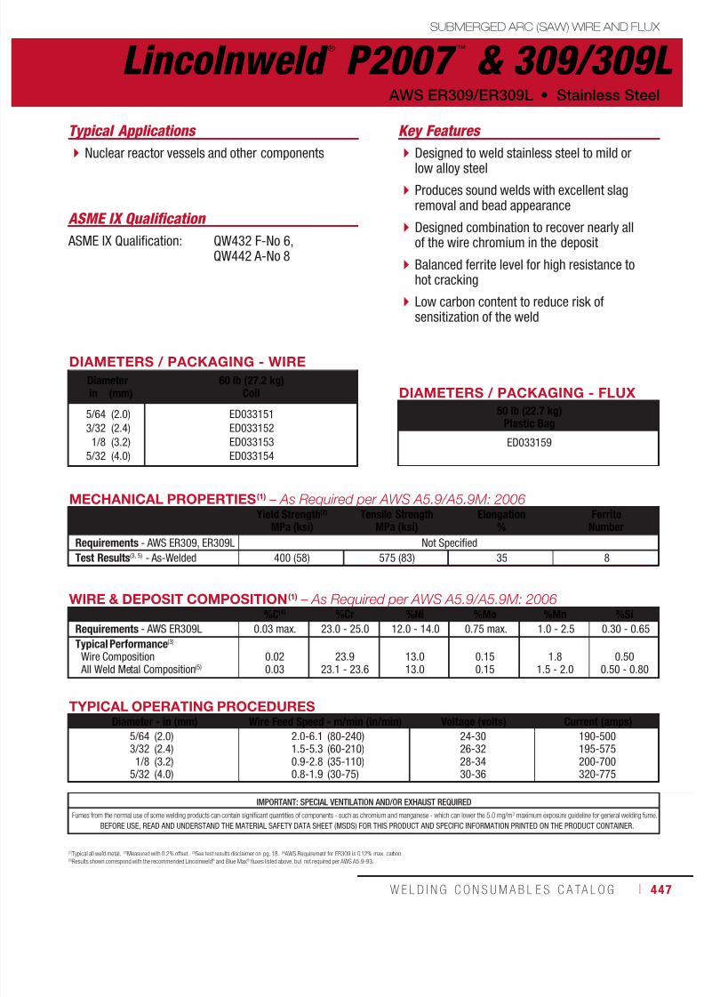
7/18/2019 c110 - Lincoln Electric Consumables 2014
http://slidepdf.com/reader/full/c110-lincoln-electric-consumables-2014 447/511W E L D I N G C O N S U M A B L E S C A TA L O G ı 447
DIAMETERS / PACKAGING - WIRE
Diameter 60 lb (27.2 kg)Coilin (mm)
5/64
3/32
1/8
5/32
(2.0)
(2.4)
(3.2)
(4.0)
ED033151
ED033152
ED033153
ED033154
SUBMERGED ARC (SAW) WIRE AND FLUX
Designed to weld stainless steel to mild or
low alloy steel Produces sound welds with excellent slagremoval and bead appearance
Designed combination to recover nearly allof the wire chromium in the deposit
Balanced ferrite level for high resistance tohot cracking
Low carbon content to reduce risk ofsensitization of the weld
Key Features Typical Applications
Nuclear reactor vessels and other components
ASME IX Qualification: QW432 F-No 6,QW442 A-No 8
ASME IX Qualification
Lincolnweld ®
P2007 ™
& 309/309L AWS ER309/ER309L • Stainless Steel
IMPORTANT: SPECIAL VENTILATION AND/OR EXHAUST REQUIRED
Fumes from the normal use of some welding products can contain significant quantities of components - such as chromium and manganese - which can lower the 5.0 mg/m3 maximum exposure guideline for general welding fume.
BEFORE USE, READ AND UNDERSTAND THE MATERIAL SAFETY DATA SHEET (MSDS) FOR THIS PRODUCT AND SPECIFIC INFORMATION PRINTED ON THE PRODUCT CONTAINER.
WIRE & DEPOSIT COMPOSITION(1) – As Required per AWS A5.9/A5.9M: 2006%C(4) %Cr %Ni %Mo %Mn %Si
Requirements - AWS ER309L 0.03 max. 23.0 - 25.0 12.0 - 14.0 0.75 max. 1.0 - 2.5 0.30 - 0.65
Typical Performance(3)
Wire Composition All Weld Metal Composition(5)
0.020.03
23.923.1 - 23.6
13.013.0
0.150.15
1.81.5 - 2.0
0.500.50 - 0.80
(1)Typical all weld metal. (2)Measured with 0.2% offset. (3)See test results disclaimer on pg. 18. (4) AWS Requirement for ER309 is 0.12% max. carbon.(5)Results shown correspond with the recommended Lincolnweld® and Blue Max® fluxes listed above, but not required per AWS A5.9-93.
TYPICAL OPERATING PROCEDURESDiameter - in (mm) Wire Feed Speed - m/min (in/min) Voltage (volts) Current (amps)
5/643/321/8
5/32
(2.0)(2.4)(3.2)(4.0)
2.0-6.11.5-5.30.9-2.80.8-1.9
(80-240)(60-210)(35-110)(30-75)
24-3026-3228-3430-36
190-500195-575200-700320-775
MECHANICAL PROPERTIES(1) – As Required per AWS A5.9/A5.9M: 2006
Yield Strength(2)
MPa (ksi)Tensile Strength
MPa (ksi)Elongation
%Ferrite
Number
Requirements - AWS ER309, ER309L Not Specified
Test Results(3, 5) - As-Welded 400 (58) 575 (83) 35 8
DIAMETERS / PACKAGING - FLUX
50 lb (22.7 kg)Plastic Bag
ED033159
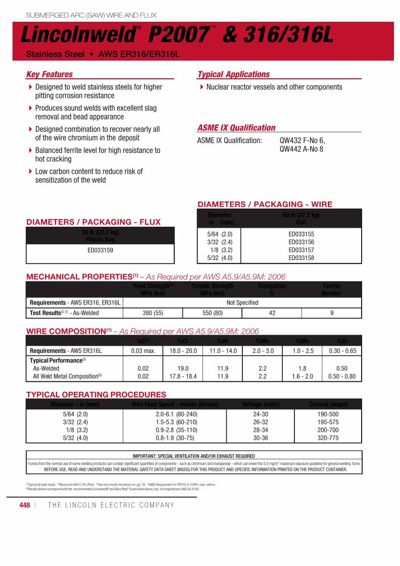
7/18/2019 c110 - Lincoln Electric Consumables 2014
http://slidepdf.com/reader/full/c110-lincoln-electric-consumables-2014 448/511448 ı T H E L I N C O L N E L E C T R I C C O M P A N Y
Designed to weld stainless steels for higher
pitting corrosion resistance Produces sound welds with excellent slagremoval and bead appearance
Designed combination to recover nearly allof the wire chromium in the deposit
Balanced ferrite level for high resistance tohot cracking
Low carbon content to reduce risk ofsensitization of the weld
Key Features
SUBMERGED ARC (SAW) WIRE AND FLUX
Typical Applications
Nuclear reactor vessels and other components
ASME IX Qualification: QW432 F-No 6,QW442 A-No 8
ASME IX Qualification
Lincolnweld ®
P2007 ™
& 316/316LStainless Steel • AWS ER316/ER316L
WIRE COMPOSITION(1) – As Required per AWS A5.9/A5.9M: 2006%C(4) %Cr %Ni %Mo %Mn %Si
Requirements - AWS ER316L 0.03 max. 18.0 - 20.0 11.0 - 14.0 2.0 - 3.0 1.0 - 2.5 0.30 - 0.65
Typical Performance(3)
As-Welded
All Weld Metal Composition(5)
0.02
0.02
19.0
17.8 - 18.4
11.9
11.9
2.2
2.2
1.8
1.6 - 2.0
0.50
0.50 - 0.80
(1)Typical all weld metal. (2)Measured with 0.2% offset. (3)See test results disclaimer on pg. 18. (4) AWS Requirement for ER316 is 0.08% max. carbon.(5)Results shown correspond with the recommended Lincolnweld® and Blue Max® fluxes listed above, but not required per AWS A5.9-93.
TYPICAL OPERATING PROCEDURES
Diameter - in (mm) Wire Feed Speed - m/min (in/min) Voltage (volts) Current (amps)
5/64
3/32
1/8
5/32
(2.0)
(2.4)
(3.2)
(4.0)
2.0-6.1
1.5-5.3
0.9-2.8
0.8-1.9
(80-240)
(60-210)
(35-110)
(30-75)
24-30
26-32
28-34
30-36
190-500
195-575
200-700
320-775
MECHANICAL PROPERTIES(1) – As Required per AWS A5.9/A5.9M: 2006Yield Strength(2)
MPa (ksi)Tensile Strength
MPa (ksi)Elongation
%Ferrite
NumberRequirements - AWS ER316, ER316L Not Specified
Test Results(3, 5) - As-Welded 380 (55) 550 (80) 42 9
IMPORTANT: SPECIAL VENTILATION AND/OR EXHAUST REQUIRED
Fumes from the normal use of some welding products can contain significant quantities of components - such as chromium and manganese - which can lower the 5.0 mg/m3 maximum exposure guideline for general welding fume.
BEFORE USE, READ AND UNDERSTAND THE MATERIAL SAFETY DATA SHEET (MSDS) FOR THIS PRODUCT AND SPECIFIC INFORMATION PRINTED ON THE PRODUCT CONTAINER.
DIAMETERS / PACKAGING - FLUX
50 lb (22.7 kg)Plastic Bag
ED033159
DIAMETERS / PACKAGING - WIRE
Diameter 60 lb (27.2 kg)Coilin (mm)
5/64
3/32
1/8
5/32
(2.0)
(2.4)
(3.2)
(4.0)
ED033155
ED033156
ED033157
ED033158
7/18/2019 c110 - Lincoln Electric Consumables 2014
http://slidepdf.com/reader/full/c110-lincoln-electric-consumables-2014 449/511W E L D I N G C O N S U M A B L E S C A TA L O G ı 449
PACKAGINGCONSUMABLES
OptionsTubes, Cans & Cartons ...................................450Reels & Stem .................................................452
Spools ............................................................ 454Coils, Boxes & Bags .......................................456Drums & Pails ................................................458
Storage and HandlingStick Electrode ............................................... 460Metal-Cored & Flux-Cored Wire ......................462Submerged Arc Flux & Wire ............................ 463
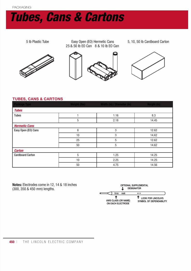
7/18/2019 c110 - Lincoln Electric Consumables 2014
http://slidepdf.com/reader/full/c110-lincoln-electric-consumables-2014 450/511450 ı T H E L I N C O L N E L E C T R I C C O M P A N Y
Tubes, Cans & Cartons PACKAGING
TUBES, CANS & CARTONS
Package Type Weight (lbs) Width (in) / Diameter (in) Height (in)
Tubes
Tubes 1 1.16 8.3
5 2.18 14.45
Hermetic Cans
Easy Open (EO) Cans 8 3 12.62
10 3 14.62
25 5 12.62
50 5 14.62
Carton
Cardboard Carton 5 1.25 14.25
10 2.25 14.25
50 4.75 14.56
Notes: Electrodes come in 12, 14 & 18 inches(300, 350 & 450 mm) lengths.
7018 H4R
OPTIONAL SUPPLEMENTALDESIGNATOR
AWS CLASS (OR NAME)
ON EACH ELECTRODE
LOOK FOR LINCOLN'S
SYMBOL OF DEPENDABILITY
5 lb Plastic Tube Easy Open (EO) Hermetic Cans 5, 10, 50 lb Cardboard Carton
25 & 50 lb EO Can 8 & 10 lb EO Can
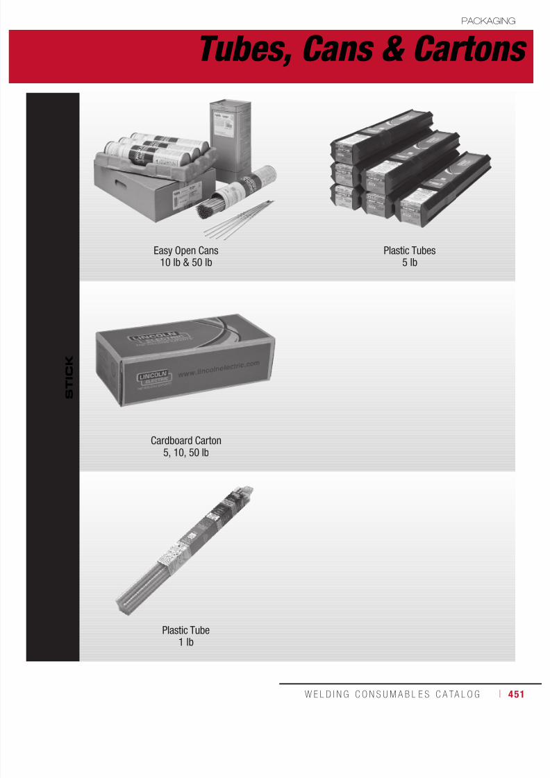
7/18/2019 c110 - Lincoln Electric Consumables 2014
http://slidepdf.com/reader/full/c110-lincoln-electric-consumables-2014 451/511W E L D I N G C O N S U M A B L E S C A TA L O G ı 451
S
T I C K
Easy Open Cans
10 lb & 50 lb
Plastic Tubes
5 lb
Cardboard Carton5, 10, 50 lb
Plastic Tube1 lb
Tubes, Cans & CartonsPACKAGING

7/18/2019 c110 - Lincoln Electric Consumables 2014
http://slidepdf.com/reader/full/c110-lincoln-electric-consumables-2014 452/511452 ı T H E L I N C O L N E L E C T R I C C O M P A N Y
Reels & Stem PACKAGING
REELS
WireType
Weight(lbs)
Wire DiameterSpecifications
"D" OuterDiameter
(in)
"W" OuterWidth(in)
"D1" Arbor HoleDiameter (in)
"D2" Pin HoleDiameter (in)
"A" Pin HoleDistance from
Axis (in)
Speed-Feed ® Reels
Solid 300 - 30 12.75 1.31 0.68 2.5
750 ≤ 1/16 in 30 12.75 1.34 0.75 2.5
750 ≥ 5/64 in 30 12.75 1.31 0.68 2.5
1000 ≤ 1/16 in 30 12.75 1.34 0.75 2.5
1000 ≥ 5/64 in 30 12.75 1.31 0.68 2.5
Flux-Cored 300 - 23.75 11.25 1.31 0.68 2.5
600 ≤ 1/16 in 30 12.75 1.34 0.75 2.5
600 ≥ 5/64 in 30 12.75 1.31 0.68 2.5
900 - 30 12.75 1.31 0.68 2.5
Precise-Trak ® Reel
Solid 1000 - 30 19.5 1.31 0.68 2.5
Speed-Feed ® SlimReel
Solid 250 - 29.75 6.18 1.31 1.31 8.75
STEM
Wire Type Weight (lbs) Base Stem Height (in)Wire Stack (in)
Inner Diameter Outer Diameter
Speed-Feed ® Stem
Solid 2200-3000 27.4 x 27.4 54 16 32 - 34
D1 D2
A
W
D
Reels Stem
Height
Base
Outer Diameter
InnerDiameter
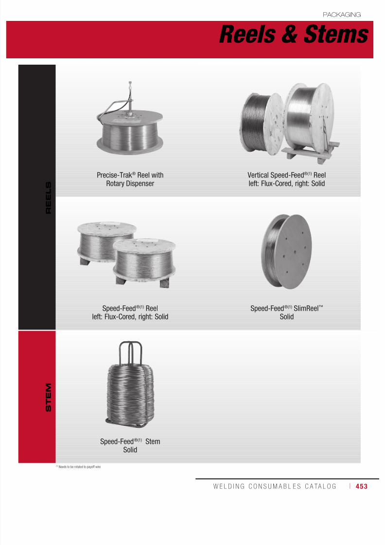
7/18/2019 c110 - Lincoln Electric Consumables 2014
http://slidepdf.com/reader/full/c110-lincoln-electric-consumables-2014 453/511W E L D I N G C O N S U M A B L E S C A TA L O G ı 453
Reels & StemsPACKAGING
Precise-Trak ® Reel with
Rotary Dispenser
Vertical Speed-Feed®(1) Reel
left: Flux-Cored, right: Solid
Speed-Feed®(1) Reelleft: Flux-Cored, right: Solid
Speed-Feed®(1) SlimReel™ Solid
Speed-Feed®(1) StemSolid
R E E L S
S T E M
(1) Needs to be rotated to payoff wire
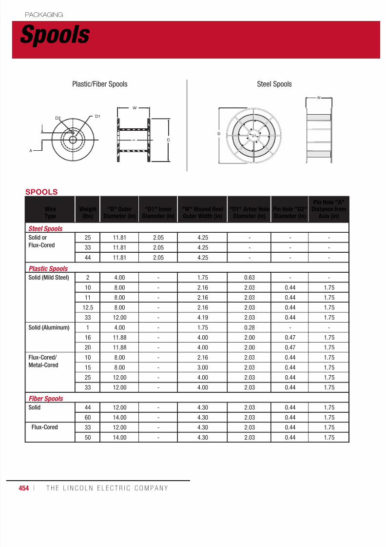
7/18/2019 c110 - Lincoln Electric Consumables 2014
http://slidepdf.com/reader/full/c110-lincoln-electric-consumables-2014 454/511454 ı T H E L I N C O L N E L E C T R I C C O M P A N Y
Spools PACKAGING
SPOOLS
WireType
Weight(lbs)
"D" OuterDiameter (in)
"D1" InnerDiameter (in)
"W" Wound ReelOuter Width (in)
"D1" Arbor HoleDiameter (in)
Pin Hole "D2"Diameter (in)
Pin Hole "A"Distance from
Axis (in)
Steel Spools
Solid or
Flux-Cored
25 11.81 2.05 4.25 - - -
33 11.81 2.05 4.25 - - -
44 11.81 2.05 4.25 - - -
Plastic Spools
Solid (Mild Steel) 2 4.00 - 1.75 0.63 - -10 8.00 - 2.16 2.03 0.44 1.75
11 8.00 - 2.16 2.03 0.44 1.75
12.5 8.00 - 2.16 2.03 0.44 1.75
33 12.00 - 4.19 2.03 0.44 1.75
Solid (Aluminum) 1 4.00 - 1.75 0.28 - -
16 11.88 - 4.00 2.00 0.47 1.75
20 11.88 - 4.00 2.00 0.47 1.75
Flux-Cored/
Metal-Cored
10 8.00 - 2.16 2.03 0.44 1.75
15 8.00 - 3.00 2.03 0.44 1.75
25 12.00 - 4.00 2.03 0.44 1.75
33 12.00 - 4.00 2.03 0.44 1.75
Fiber Spools
Solid 44 12.00 - 4.30 2.03 0.44 1.75
60 14.00 - 4.30 2.03 0.44 1.75
Flux-Cored 33 12.00 - 4.30 2.03 0.44 1.75
50 14.00 - 4.30 2.03 0.44 1.75
D2 D1
A
W
D
Plastic/Fiber Spools Steel Spools

7/18/2019 c110 - Lincoln Electric Consumables 2014
http://slidepdf.com/reader/full/c110-lincoln-electric-consumables-2014 455/511W E L D I N G C O N S U M A B L E S C A TA L O G ı 455
SpoolsPACKAGING
S P O O L S
Steel Spool
Solid & Flux-Cored - 33 lb
Plastic Spool
Flux-Cored - 25 lb, 1 lb
Plastic SpoolSolid, Mild Steel - 33 lb, 12.5 lb, 2 lb
Plastic SpoolSolid, Aluminum - 16 lb, 1 lb
Fiber SpoolSolid, Mild Steel - 60 lb, Flux-Cored - 33 lb, 50 lb

7/18/2019 c110 - Lincoln Electric Consumables 2014
http://slidepdf.com/reader/full/c110-lincoln-electric-consumables-2014 456/511456 ı T H E L I N C O L N E L E C T R I C C O M P A N Y
Coils, Boxes & Bags PACKAGING
BOXES
Wire Type Weight (lbs)Outside Dimensions
L x W x H (in)Core Dimensions
(in)
Accu-Pak ® Box
Solid (Aluminum) 275 x 300 24 x 24 x 32 14
Solid (Mild Steel) 500 21 x 21 x 28 -
1000 24 x 24 x 32 -
BAGS
Wire Type Weight (lbs) SolidDimensions (in)
Paper Bag / Plastic Bag
Flux 50 -
Bulk Bag
Flux 2600 - 3000 43 x 43 x 48(1)
COILS
Wire Type Weight (lbs)Wire DiameterSpecifications
"D" OuterDiameter (in)
"D1" InnerDiameter (in)
"W" Wound ReelOuter Width (in)
Coils
Solid 60 ≤ 1/16 in 16.50 12.00 4.40
60 ≥ 5/64 in 16.50 12.00 4.60
Flux-Cored 13.5 & 14 - 9.50 6.70 3.00
14 (56 lb HS Pail) - 9.50 6.70 3.00
50 & 60 - 16.50 12.00 4.60
D1 D
W
Coils Boxes
(1)Values are maximums.
H
W

7/18/2019 c110 - Lincoln Electric Consumables 2014
http://slidepdf.com/reader/full/c110-lincoln-electric-consumables-2014 457/511W E L D I N G C O N S U M A B L E S C A TA L O G ı 457
B
O X E S
Coils, Boxes & BagsPACKAGING
C O I L S
B A G S
Flux-Cored
13.5 lb. Coil (54 lb HS Pail)
Flux-Cored
60 lb
Solid Wire
60 lb
Paper Bag Plastic Bag Bulk Bag
Accu-Pak ® Boxes1000 & 500 lb

7/18/2019 c110 - Lincoln Electric Consumables 2014
http://slidepdf.com/reader/full/c110-lincoln-electric-consumables-2014 458/511458 ı T H E L I N C O L N E L E C T R I C C O M P A N Y
Drums & Pails PACKAGING
DRUMS
Wire Type Weight (lbs)Outer Diameter
(in)Outer Height
(in)Core InsideDiameter Core Height
Speed-Feed ® Drum
Solid 300 23.4 17.8 16 17
600 23.4 34.8 16 34
1000 23.4 34.8 16 34
Flux-Cored 125 23.4 11.1 16 10
300 23.4 17.8 16 17
500 and 600 23.4 34.8 16 17
Accu-Trak ® Drum
Solid 250 23.4 19.7 - -
500 20.4 32.6 - -
1000 23.4 34.8 - -
Flux-Cored 300, 400 and 500 20.4 32.6 8.4 31.5
500 and 600 23.4 34.8 8.4 34
Metal-Cored 500 20.4 32.6 8.4 31.5
Steel Drum
Flux 550 22.75 33.50 - -
PAILS
Wire Type Weight (lbs)Outer Diameter
(in)Outer Height
(in)Core InsideDiameter Core Height
Hermetically Sealed Pail
Flux 50 12 14.75 - -
D
H
Drums

7/18/2019 c110 - Lincoln Electric Consumables 2014
http://slidepdf.com/reader/full/c110-lincoln-electric-consumables-2014 459/511W E L D I N G C O N S U M A B L E S C A TA L O G ı 459
D R U M S
P A I L
Drums & PailsPACKAGING
Accu-Trak ® /Speed-Feed®(1) Drums
(1) Needs to be rotated to payoff wire. (2)This product does not come on a pallet. If your application requires a pallet, please contact your local Lincoln Electric sales representative.
Steel Drum(2)
Hermetically Sealed Pail Pail as Master

7/18/2019 c110 - Lincoln Electric Consumables 2014
http://slidepdf.com/reader/full/c110-lincoln-electric-consumables-2014 460/511460 ı T H E L I N C O L N E L E C T R I C C O M P A N Y
Storage & Handling PACKAGING
Stick Electrodes
Storing Low Hydrogen ElectrodesLow hydrogen electrodes must be dry to perform
properly. Unopened hermetically sealed containersprovide excellent protection in good storageconditions. Opened cans or electrodes should bestored in a cabinet at 120°-150°C (250°-300°F).
Moisture resistant electrodes with an “R” suffixhave a high resistance to coating moisture pick-up.
However, all low hydrogen electrodes should bestored properly, even those with an “R” suffix.Standard EXX18 electrodes should be supplied towelders twice per shift. Moisture resistant types
may be exposed for up to 9 hours. Specific coderequirements may indicate exposure limitsdifferent from these guidelines.
Depending on the amount of moisture absorbedand other factors, moisture pickup can degradeweld quality in various ways:
1. Moisture in low hydrogen electrodes maycause porosity. This porosity could becompletely subsurface and require x-rayinspection or destructive testing. The porositycould also be visible, external porosity.
2. High moisture can also lead to excessive slagfluidity, a rough weld surface, and difficult slagremoval.
3. Excessive moisture in low hydrogen electrodeswill lead to elevated levels of diffusible hydrogenwhich, in turn, can lead to hydrogen-inducedweld cracking and/or underbead cracking.
Re-drying Low Hydrogen ElectrodesRe-drying, when done correctly, restores theelectrodes’ ability to deposit quality welds. Proper
re-drying temperature depends upon the electrodetype and its condition. One hour at the listed finaltemperature is satisfactory. DO NOT dry electrodesat higher temperatures. Several hours at lowertemperatures is not equivalent to using thespecified requirements.
Electrodes of the E8018 and higher strengthclassifications should be given no more than three1-hour re-dries in the 370°-430°C (700°-800°F)
range. This minimizes the possibility of oxidation ofalloys in the coating which would result in lower than
normal tensile or impact properties. Any low hydrogen electrode should be discarded ifexcessive re-drying causes the coating to becomefragile and flake or break off while welding, or if thereis a noticeable difference in handling or arccharacteristics, such as insufficient arc force.
Electrodes to be re-dried should be removed from thecan and spread out in the oven because each electrodemust reach the drying temperature.
Storing Cellulosic ElectrodesElectrodes in unopened Lincoln cans or cartons retainthe proper moisture content indefinitely when stored ingood condition.
If exposed to humid air for long periods of time,electrodes from opened containers may pick up enoughmoisture to affect operating characteristics or weldquality. If moisture appears to be a problem, storeelectrodes from the opened containers in heated cabinetsat 40° to 50°C (100° to 120°F).
Storing and Re-drying Non-Low Hydrogen ElectrodesElectrodes in unopened Lincoln cans or cartons retainthe proper moisture content indefinitely when stored ingood condition.
If exposed to humid air for long periods of time,electrodes from opened containers may pick up enoughmoisture to affect operating characteristics or weldquality. If moisture appears to be a problem, storeelectrodes from the opened containers in heatedcabinets at 40° to 50°C (100° to 120°F). DO NOT usehigher temperatures.
Some electrodes from wet containers or long exposureto high humidity can be re-dried. Follow the proceduresbelow for each type.
Using longer drying times or higher temperaturescan easily damage the electrodes.
For drying, remove the electrodes from the containerand spread them out in the furnace because eachelectrode must reach the drying temperature.
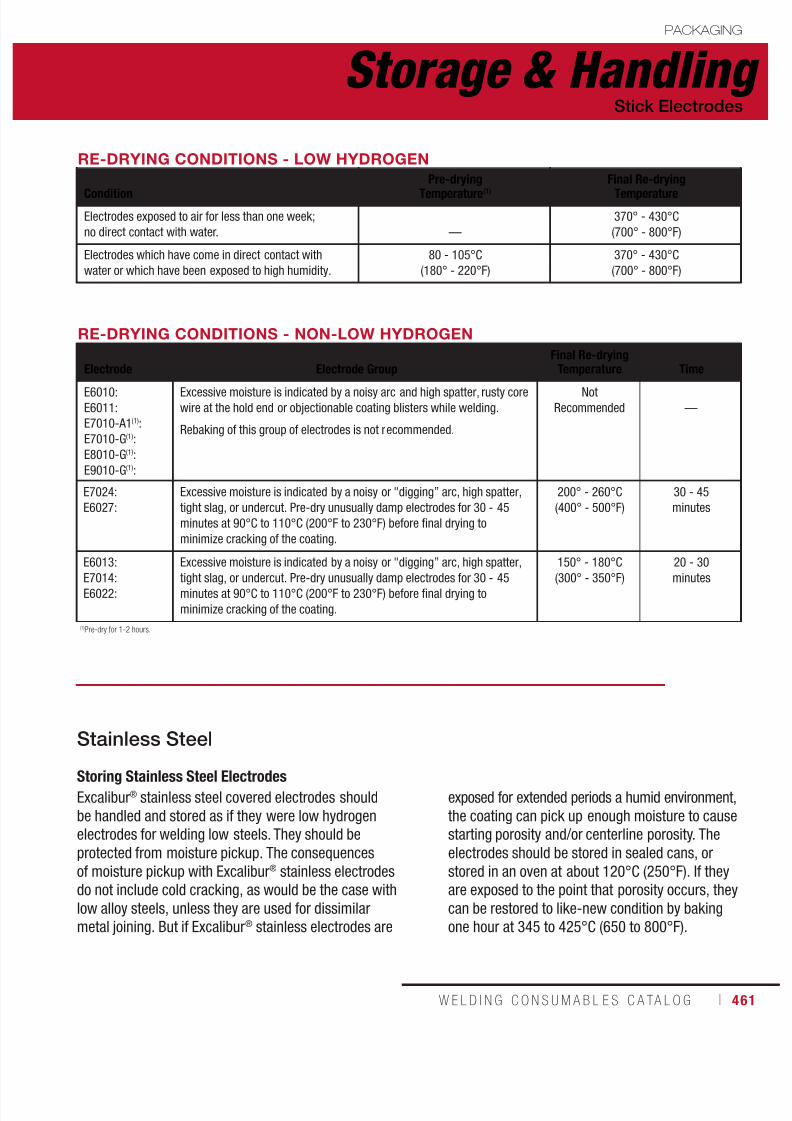
7/18/2019 c110 - Lincoln Electric Consumables 2014
http://slidepdf.com/reader/full/c110-lincoln-electric-consumables-2014 461/511W E L D I N G C O N S U M A B L E S C A TA L O G ı 461
Storage & HandlingPACKAGING
Stick Electrodes
RE-DRYING CONDITIONS - LOW HYDROGEN
Condition
Pre-drying
Temperature(1)
Final Re-drying
Temperature
Electrodes exposed to air for less than one week;
no direct contact with water. —
370° - 430°C
(700° - 800°F)
Electrodes which have come in direct contact with
water or which have been exposed to high humidity.
80 - 105°C
(180° - 220°F)
370° - 430°C
(700° - 800°F)
RE-DRYING CONDITIONS - NON-LOW HYDROGEN
Electrode Electrode GroupFinal Re-drying
Temperature Time
E6010:
E6011:
E7010-A1(1):
E7010-G(1):
E8010-G(1):
E9010-G(1):
Excessive moisture is indicated by a noisy arc and high spatter, rusty core
wire at the hold end or objectionable coating blisters while welding.
Rebaking of this group of electrodes is not recommended.
Not
Recommended —
E7024:
E6027:
Excessive moisture is indicated by a noisy or "digging” arc, high spatter,
tight slag, or undercut. Pre-dry unusually damp electrodes for 30 - 45
minutes at 90°C to 110°C (200°F to 230°F) before final drying to
minimize cracking of the coating.
200° - 260°C
(400° - 500°F)
30 - 45
minutes
E6013:
E7014:E6022:
Excessive moisture is indicated by a noisy or "digging” arc, high spatter,
tight slag, or undercut. Pre-dry unusually damp electrodes for 30 - 45minutes at 90°C to 110°C (200°F to 230°F) before final drying to
minimize cracking of the coating.
150° - 180°C
(300° - 350°F)
20 - 30
minutes
(1)Pre-dry for 1-2 hours.
Storing Stainless Steel ElectrodesExcalibur® stainless steel covered electrodes shouldbe handled and stored as if they were low hydrogenelectrodes for welding low steels. They should beprotected from moisture pickup. The consequencesof moisture pickup with Excalibur® stainless electrodesdo not include cold cracking, as would be the case withlow alloy steels, unless they are used for dissimilarmetal joining. But if Excalibur® stainless electrodes are
Stainless Steel
exposed for extended periods a humid environment,the coating can pick up enough moisture to causestarting porosity and/or centerline porosity. Theelectrodes should be stored in sealed cans, orstored in an oven at about 120°C (250°F). If theyare exposed to the point that porosity occurs, theycan be restored to like-new condition by bakingone hour at 345 to 425°C (650 to 800°F).

7/18/2019 c110 - Lincoln Electric Consumables 2014
http://slidepdf.com/reader/full/c110-lincoln-electric-consumables-2014 462/511462 ı T H E L I N C O L N E L E C T R I C C O M P A N Y
Storage & Handling PACKAGING
Metal-Cored & Flux-Cored Wire
Shelf Life
As a general rule, The Lincoln Electric Company estimates maximum storage time for mild and low alloy steelconsumables to be 3 years. This estimate is for material in the original, undamaged packages that is storedindoors at up to ~70% relative humidity and that are protected from the weather or other adverse conditions.Packages should be stored under conditions that minimize the likelihood of temperature variations that causemoisture condensation on the consumables.
These estimates are based on what we know about the packaging materials and the frequency of productimprovements. Since actual storage conditions vary widely across geographical regions and from one customerto another, it is not possible to be more specific. For packages that are not hermetically sealed, a shorter storagetime is advisable under sustained severe humidity conditions but is not possible to estimate. Note that productstored for longer than 3 years, may still be suitable for use. It depends on the product and the condition it is in.
Dispose of any wire or rod that has visible signs of rust.
Customers are not encouraged to store consumables for extended periods of time. It is advisable to maintainturnover in inventory to ensure the products are as close to their as manufactured conditions as can bereasonably expected. The general guidelines above are provided for those unplanned instances where productis stored longer than originally anticipated.
Storage of Unopened Packages
FCAW products should be stored in the original, unopened packaging until ready to use. To maintain the integrity
of these products, electrodes must be protected from the atmosphere. All flux cored electrodes, regardless ofpackage, should be protected from condensation, including rain or snow. To ensure that condensation does notform on the product, it is recommended that the electrode be stored in an environment that is kept above thedew point temperature for a given relative humidity. Minimizing temperature variation will also help to protectthe electrode from moisture condensation. It is advisable to maintain turnover in inventory to ensure the productis as close to the manufactured condition as possible.
For applications in which the weld metal hydrogen must be controlled (usually 8 mL/100g or lower), or where
shipping and storage conditions are not controlled or known; only hermetically sealed packaging is recommended.
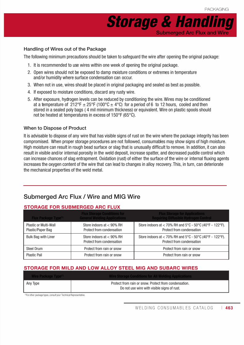
7/18/2019 c110 - Lincoln Electric Consumables 2014
http://slidepdf.com/reader/full/c110-lincoln-electric-consumables-2014 463/511W E L D I N G C O N S U M A B L E S C A TA L O G ı 463
Storage & HandlingPACKAGING
Submerged Arc Flux and Wire
Submerged Arc Flux / Wire and MIG Wire
STORAGE FOR MILD AND LOW ALLOY STEEL MIG AND SUBARC WIRES
Wire Package Type(1) Wire Storage Conditions for All Welding Applications
Any Type Protect from rain or snow. Protect from condensation.
Do not use wire with visible signs of rust.
STORAGE FOR SUBMERGED ARC FLUX
Flux Package Type(1)Flux Storage Conditions for
General Welding ApplicationsFlux Storage for Applications
Requiring Diffusible Hydrogen Control
Plastic or Multi-Wall
Plastic/Paper Bag
Store indoors at < 90% RH
Protect from condensation
Store indoors at < 70% RH and 5°C - 50°C (40°F - 122°F).
Protect from condensation
Bulk Bag with Liner Store indoors at < 90% RHProtect from condensation
Store indoors at < 70% RH and 5°C - 50°C (40°F - 122°F).Protect from condensation
Steel Drum Protect from rain or snow Protect from rain or snow
Plastic Pail Protect from rain or snow Protect from rain or snow
(1)For other package types, consult your Technical Representative.
Handling of Wires out of the Package
The following minimum precautions should be taken to safeguard the wire after opening the original package:1. It is recommended to use wires within one week of opening the original package.
2. Open wires should not be exposed to damp moisture conditions or extremes in temperatureand/or humidity where surface condensation can occur.
3. When not in use, wires should be placed in original packaging and sealed as best as possible.
4. If exposed to moisture conditions, discard any rusty wire.
5. After exposure, hydrogen levels can be reduced by conditioning the wire. Wires may be conditionedat a temperature of 212°F ± 25°F (100°C ± 4°C) for a period of 6 to 12 hours, cooled and thenstored in a sealed poly bags ( 4 mil minimum thickness) or equivalent. Wire on plastic spools shouldnot be heated at temperatures in excess of 150°F (65°C).
When to Dispose of Product
It is advisable to dispose of any wire that has visible signs of rust on the wire where the package integrity has beencompromised. When proper storage procedures are not followed, consumables may show signs of high moisture.High moisture can result in rough bead surface or slag that is unusually difficult to remove. In addition, it can alsoresult in visible and/or internal porosity in the weld deposit, increase spatter, and decreased puddle control whichcan increase chances of slag entrapment. Oxidation (rust) of either the surface of the wire or internal fluxing agentsincreases the oxygen content of the wire that can lead to changes in alloy recovery. This, in turn, can deterioratethe mechanical properties of the weld metal.

7/18/2019 c110 - Lincoln Electric Consumables 2014
http://slidepdf.com/reader/full/c110-lincoln-electric-consumables-2014 464/511464 ı T H E L I N C O L N E L E C T R I C C O M P A N Y
Storage & Handling PACKAGING
Submerged Arc Flux and Wire
Re-Drying Flux
To re-dry fluxes other than MIL800-H & MIL800-HPNi
• Remove flux from its original packaging and place in a clean oven set between 260°-480°C (500°-900°F).
• Leave in oven long enough to raise the temperature of the entire bulk of flux to your set temperature for aminimum of one hour.
• For ovens in which heating rods are inserted into the flux, do not let the temperature of flux adjacent to therods exceed 480°C (900°F).
For MIL800-H and MIL800-HPNi fluxes
Follow all previous procedures, with the following changes:
• Set temperature between 120°-205°C (250°-400°F).
• For ovens in which heating rods are inserted into the flux, do not let the temperature of flux adjacent to therods exceed 205°C (400°F).
For all other fluxes requiring diffusible Follow all previous procedures, with the following changes:
• Set temperature at approximately 425°C (800°F).
Lincoln Electric submerged arc welding flux can be used directly from its original, undamaged package, if it hasbeen stored according to the conditions listed in the chart above.
When proper procedures are not followed, flux may show signs of moisture. These can include porosity, a roughbead surface or slag that is unusually difficult to remove. In many instances these fluxes can be re-dryed ingeneral welding applications.
Recycling Flux
• Remove slag, metal, mill scale, and any other contaminants from the flux.• Prevent damage to the flux from heavy impingement in flux transport systems.
• Avoid the separation of different sized particles in cyclones or “dead” corners.
• Remove excess fines from recycled fluxes.
• For optimal welding characteristics, it is recommended to add at least 20% new flux by weight to recycled flux.
Non-consumed flux may be collected from the finished weld and recycled.To do so, please follow these procedures:
Re-Drying & Recycling Flux

7/18/2019 c110 - Lincoln Electric Consumables 2014
http://slidepdf.com/reader/full/c110-lincoln-electric-consumables-2014 465/511W E L D I N G C O N S U M A B L E S C A TA L O G ı 465
CONSUMABLES
APPENDIX
AWS Classification SystemStick ............................................................466MIG, TIG & Metal-Cored ................................ 467
Flux-Cored ...................................................468Submerged Arc ............................................470
General InformationStick ElectrodeTypes of Coating & Current ........................... 474 ASME Boiler & Pressure Vessel Code ............475
Submerged ArcFlux Types & General Characteristics ............476Selecting Flux/Wire Combinations ................477
HardfacingCross Checking ............................................479
AluminumTypical Operating Procedures .......................480Typical Joint Designs .................................... 482
Innershield®
Wire Selection Guide ....................................483
Agency Approvals ................................. 485
Safety Guidelines .................................. 504
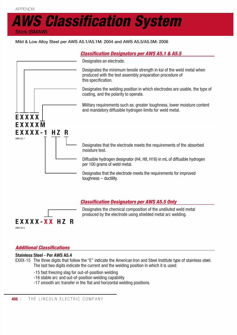
7/18/2019 c110 - Lincoln Electric Consumables 2014
http://slidepdf.com/reader/full/c110-lincoln-electric-consumables-2014 466/511466 ı T H E L I N C O L N E L E C T R I C C O M P A N Y
AWS Classification System APPENDIX
Classification Designators per AWS A5.1 & A5.5
Designates an electrode.
Designates the minimum tensile strength in ksi of the weld metal whenproduced with the test assembly preparation procedure ofthis specification.
Designates the welding position in which electrodes are usable, the type ofcoating, and the polarity to operate.
Military requirements such as: greater toughness, lower moisture contentand mandatory diffusible hydrogen limits for weld metal.
Designates that the electrode meets the requirements of the absorbedmoisture test.
Diffusible hydrogen designator (H4, H8, H16) in mL of diffusible hydrogenper 100 grams of weld metal.
Designates that the electrode meets the requirements for improvedtoughness – ductility.
Stick (SMAW)
Mild & Low Alloy Steel per AWS A5.1/A5.1M: 2004 and AWS A5.5/A5.5M: 2006
E X X X XE X X X X ME X X X X - 1 H Z R
Classification Designators per AWS A5.5 Only
Designates the chemical composition of the undiluted weld metalproduced by the electrode using shielded metal arc welding.
E X X X X - X X H Z R
AWS A5.1
AWS A5.5
Additional Classifications
Stainless Steel - Per AWS A5.4EXXX-15 The three digits that follow the “E” indicate the American Iron and Steel Institute type of stainless steel.
The last two digits indicate the current and the welding position in which it is used:
-15 fast freezing slag for out-of-position welding-16 stable arc and out-of-position welding capability-17 smooth arc transfer in the flat and horizontal welding positions.
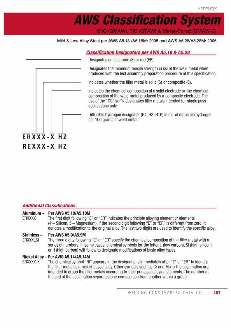
7/18/2019 c110 - Lincoln Electric Consumables 2014
http://slidepdf.com/reader/full/c110-lincoln-electric-consumables-2014 467/511W E L D I N G C O N S U M A B L E S C A TA L O G ı 467
AWS Classification System APPENDIX
Classification Designators per AWS A5.18 & A5.28
Designates an electrode (E) or rod (ER).
Designates the minimum tensile strength in ksi of the weld metal whenproduced with the test assembly preparation procedure of this specification.
Indicates whether the filler metal is solid (S) or composite (C).
Indicates the chemical composition of a solid electrode or the chemicalcomposition of the weld metal produced by a composite electrode. Theuse of the “GS” suffix designates filler metals intended for single passapplications only.
Diffusible hydrogen designator (H4, H8, H16) in mL of diffusible hydrogenper 100 grams of weld metal.
MIG (GMAW), TIG (GTAW) & Metal-Cored (GMAW-C)
Mild & Low Alloy Steel per AWS A5.18 /A5.18M: 2005 and AWS A5.28/A5.28M: 2005
E R X X X - X H Z
R E X X X - X H Z
Additional Classifications
Aluminum – Per AWS A5.10/A5.10MERXXXX The first digit following “E” or “ER” indicates the principle alloying element or elements
(4 – Silicon, 5 – Magnesium). If the second digit following “E” or “ER” is different from zero, itdenotes a modification to the original alloy. The last two digits are used to identify the specific alloy.
Stainless – Per AWS A5.9/A5.9MERXXXLSi The three digits following “E” or “ER” specify the chemical composition of the filler metal with a
series of numbers. In some cases, chemical symbols for the letter L (low carbon), Si (high silicon),or H (high carbon) will follow to designate modifications of basic alloy types.
Nickel Alloy – Per AWS A5.14/A5.14MERXXXX-X The chemical symbol “Ni” appears in the designations immediately after “E” or “ER” to identify
the filler metal as a nickel-based alloy. Other symbols such as Cr and Mo in the designation areintended to group the filler metals according to their principal alloying elements. The number atthe end of the designation separates one composition from another within a group.
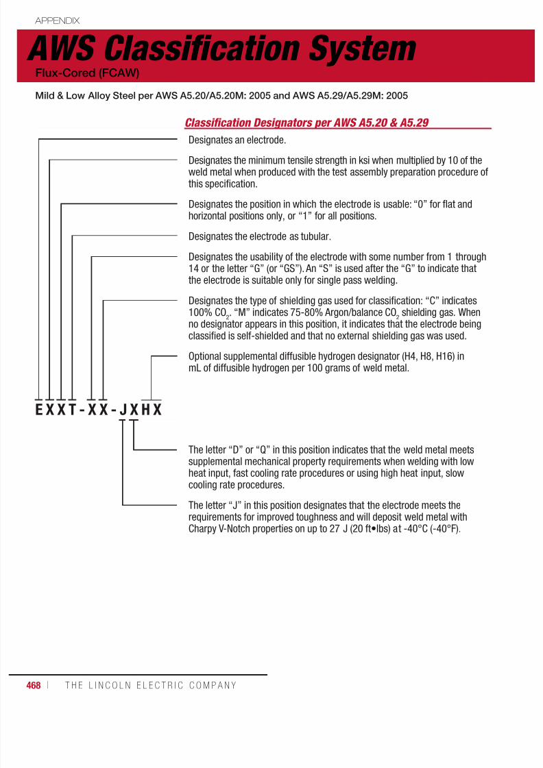
7/18/2019 c110 - Lincoln Electric Consumables 2014
http://slidepdf.com/reader/full/c110-lincoln-electric-consumables-2014 468/511468 ı T H E L I N C O L N E L E C T R I C C O M P A N Y
AWS Classification System APPENDIX
Classification Designators per AWS A5.20 & A5.29
Designates an electrode.
Designates the minimum tensile strength in ksi when multiplied by 10 of theweld metal when produced with the test assembly preparation procedure ofthis specification.
Designates the position in which the electrode is usable: “0” for flat andhorizontal positions only, or “1” for all positions.
Designates the electrode as tubular.
Designates the usability of the electrode with some number from 1 through14 or the letter “G” (or “GS”). An “S” is used after the “G” to indicate thatthe electrode is suitable only for single pass welding.
Designates the type of shielding gas used for classification: “C” indicates100% CO
2. “M” indicates 75-80% Argon/balance CO
2 shielding gas. When
no designator appears in this position, it indicates that the electrode beingclassified is self-shielded and that no external shielding gas was used.
Optional supplemental diffusible hydrogen designator (H4, H8, H16) inmL of diffusible hydrogen per 100 grams of weld metal.
The letter “D” or “Q” in this position indicates that the weld metal meetssupplemental mechanical property requirements when welding with lowheat input, fast cooling rate procedures or using high heat input, slowcooling rate procedures.
The letter “J” in this position designates that the electrode meets therequirements for improved toughness and will deposit weld metal with
Charpy V-Notch properties on up to 27 J (20 ft•lbs) at -40°C (-40°F).
Flux-Cored (FCAW)
Mild & Low Alloy Steel per AWS A5.20/A5.20M: 2005 and AWS A5.29/A5.29M: 2005
E X X T - X X - J X H X

7/18/2019 c110 - Lincoln Electric Consumables 2014
http://slidepdf.com/reader/full/c110-lincoln-electric-consumables-2014 469/511W E L D I N G C O N S U M A B L E S C A TA L O G ı 469
AWS Classification System APPENDIX
Additional Classifications
Stainless Steel - Per AWS A5.22/A5.22MEXXXTX-X The three digits that follow “E” designate the chemical composition of the weld metal. The digit following
“T” designates the position in which the electrode is usable: “0” for flat and horizontal positions only, or“1” for all positions.
E X X T X - X X - J X H X
Designates the usability of the electrode with the number 1, 4, 5, 6, 7, 8,or 11. The letter “G” in this position indicates that the polarity and generaloperating characteristics are not specified.
Two, three or four digits are used to designate the chemical compositionof the deposited weld metal. The letter “G” indicates that the chemicalcomposition is not specified.
Classification Designators per AWS A5.29 Only
Mild & Low Alloy Steel per AWS A5.20/A5.20M: 2005 and AWS A5.29/A5.29M: 2005
Flux-Cored (FCAW)

7/18/2019 c110 - Lincoln Electric Consumables 2014
http://slidepdf.com/reader/full/c110-lincoln-electric-consumables-2014 470/511470 ı T H E L I N C O L N E L E C T R I C C O M P A N Y
AWS Classification System APPENDIX
Submerged Arc (SAW) Flux & Electrode
Mild & Low Alloy Steel - Per AWS A5.17/A5.17M: 1997 and AWS A5.23/A5.23M: 2007
Classification Designators per AWS A5.17 & A5.23
Designates a flux. If followed by the letter “S,” the flux is a crushed slagor a blend of crushed slag with unused (virgin) flux.
Designates the minimum tensile strength in ksi when multiplied by10 of the weld metal deposited with the flux and some classificationof electrode.
Designates the condition of heat treatment in which the tests wereconducted: “A” is for as-welding and “P” is for postweld heat treated.
Indicates the temperature in °F at or above which the weld metal meets
the requirement for Charpy V-Notch impact toughness of 27 J (20 ft•lbf).Two digits are used for test temperatures of -100°F or lower.
The letter “E” at the beginning of each classification stands for electrode.The letter “C” will follow the “E” if it is a composite electrode.
Indicates whether the electrode is L – low manganese, M – mediummanganese or H – high manganese.
The classification is based upon low dilution weld metal obtained with aparticular flux. The numerical suffix refers to the approximate carboncontent in hundredths of one percent.
Indicates that the electrode is made from a heat of silicon-killed steel.
Optional supplemental diffusible hydrogen designator (H4, H8, H16) inmL of diffusible hydrogen per 100 grams of weld metal.
Classification Designators per AWS A5.23 Only
Indicates the chemical composition of a solid electrode or the undiluted
weld metal obtained with a composite electrode and particular flux.Usually a combination of letters, numbers and elements (see next page).
F X P X - E C M X X K - H ZF X P X - E C X X X - H Z
MILD STEEL EXAMPLESF7A6-EM12K is a complete designation for a flux-electrode combination. It refers to a flux that will produce weld metal which, in the as-welded condition,will have a tensile strength of 70,000 to 95,000 psi and Charpy V-Notch impact strength of at least 20 ft•lbf at -60°F when produced with an EM12Kelectrode under the conditions called for in this specification. The absence of an “S” in the second position indicates that the flux being used is a virgin flux.F7P4-EC1 is a complete designation for a flux-composite electrode combination when the trade name of the electrode used in the classification is indicatedas well. It refers to a virgin flux that will produce weld metal with that electrode which, in the postweld heat treated condition, will have a tensile strength of70,000 to 95,000 psi and Charpy V-Notch energy of at least 20 ft•lbf at -40°F under the conditions called for in this specification.
LOW ALLOY STEEL EXAMPLESF9P0-EB3-B3 is a complete designation for a flux-electrode combination. It refers to a flux that will produce weld metal which, in the postweld heat treatedcondition, will have a tensile strength of 90,000 to 110,000 psi and Charpy V-Notch impact strength of at least 20 ft•lbf at 0°F when produced with an EB3electrode under the conditions called for in this specification. The composition of the weld metal will meet the requirements for a B3 designation.

7/18/2019 c110 - Lincoln Electric Consumables 2014
http://slidepdf.com/reader/full/c110-lincoln-electric-consumables-2014 471/511W E L D I N G C O N S U M A B L E S C A TA L O G ı 471
AWS Classification System APPENDIX
Submerged Arc (SAW) Flux & Electrode
The electrode classification identifies the chemical
composition of the electrode. The following paragraphshighlight the differences between these electrodes andelectrode groups and indicate typical applications.
Mild Steel Electrodes
EL8, EL8K, EL12, EM11K, EM12, EM12K, EM13K,EM14K, EM15K, EH10K, EH11K, EH12K and EH14 –Carbon steel electrodes which vary from one another intheir carbon, manganese, and silicon contents. EM14Kelectrodes also contain small additions of titanium,although they are considered carbon steel electrodes.
Low Alloy Electrodes
EA1, EA2, EA3, EA3K, and EA4 (C-Mo Steel) –Similar to the medium manganese and highmanganese carbon steel electrodes shown aboveexcept that 0.5% molybdenum is added.
EB1, EB2, EB2H, EB3, EB5, EB6, EB6H, EB8, andEB9 (Cr-Mo Steel) – Produce weld metal containingbetween 0.5% and 10% chromium and between0.5% and 1% molybdenum.
The letter “R” when added as a suffix to the EB2 or EB3electrode classification or to the B2 or B3 weld metaldesignation is an optional supplemental designatorindicating that the electrode will meet the reducedresidual limits necessary to meet “X” factorrequirements for step cooling applications.
Since all Cr-Mo weld deposits will air harden in stillair, both preheat and postweld heat treatment (PWHT)are required for most applications.
EB9 is a 9% Cr-I % Mo electrode modified withniobium (columbium) and vanadium designed toprovide improved creep strength, and oxidationand corrosion resistance at elevated temperatures.
Classification Descriptions for AWS A5.17 & A5.23
ENi1, ENi1K, ENi2, and ENi3 (Ni Steel) – Designed
to produce weld metal with increased strengthwithout being hardenable or with increased notchtoughness at temperatures as low as -100°F(-73°C) or lower. They have been specified withnickel contents which fall into three nominal levelsof 1 % Ni, 2.5% Ni, and 3.5% Ni.
ENi4, ENi5, EFl, EF2, and EF3 (Ni-Mo Steel) –Contain between 0.5% and 2% nickel and be-tween 0.25% and 0.5% molybdenum.
EF4, EF5, and EF6 (Cr-Ni-Mo Steel) - Acombination of Cr, Ni, and Mo develop the strengthlevels and notch toughness required for a numberof high-strength, low-alloy or micro-alloyedstructural steels.
EM2, EM3, and EM4 (High-Strength, Low AlloySteel) – May contain a combination of Cr, Ni, Mo,Ti, Zr and Al.
EW (Weathering Steel) – Designed to produceweld metal that matches the corrosion resistance
and the coloring of the ASTM weathering-typestructural steels. These special properties areachieved by the addition of about 0.5% copper tothe weld metal.
EG (General Low-Alloy Steel) – Indicates that theelectrode is of a general classification. It is generalbecause not all of the particular requirementsspecified for each of the other classifications arespecified for this classification.
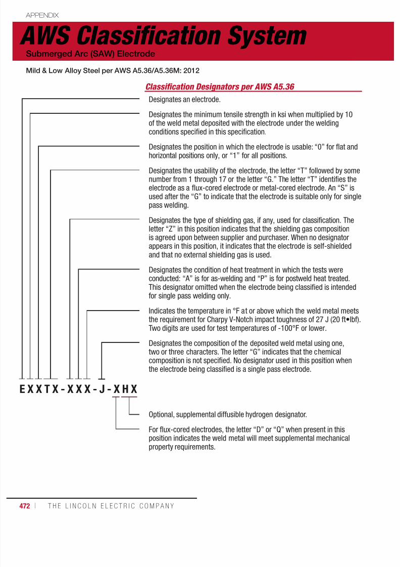
7/18/2019 c110 - Lincoln Electric Consumables 2014
http://slidepdf.com/reader/full/c110-lincoln-electric-consumables-2014 472/511472 ı T H E L I N C O L N E L E C T R I C C O M P A N Y
APPENDIX
AWS Classification System Submerged Arc (SAW) Electrode
Mild & Low Alloy Steel per AWS A5.36/A5.36M: 2012
Classification Designators per AWS A5.36
Designates an electrode.
Designates the minimum tensile strength in ksi when multiplied by 10of the weld metal deposited with the electrode under the weldingconditions specified in this specification.
Designates the position in which the electrode is usable: “0” for flat andhorizontal positions only, or “1” for all positions.
Designates the usability of the electrode, the letter “T” followed by somenumber from 1 through 17 or the letter “G.” The letter “T” identifies theelectrode as a flux-cored electrode or metal-cored electrode. An “S” is
used after the “G” to indicate that the electrode is suitable only for singlepass welding.
Designates the type of shielding gas, if any, used for classification. Theletter “Z” in this position indicates that the shielding gas compositionis agreed upon between supplier and purchaser. When no designatorappears in this position, it indicates that the electrode is self-shieldedand that no external shielding gas is used.
Designates the condition of heat treatment in which the tests wereconducted: “A” is for as-welding and “P” is for postweld heat treated.
This designator omitted when the electrode being classified is intendedfor single pass welding only.
Indicates the temperature in °F at or above which the weld metal meetsthe requirement for Charpy V-Notch impact toughness of 27 J (20 ft•lbf).Two digits are used for test temperatures of -100°F or lower.
Designates the composition of the deposited weld metal using one,two or three characters. The letter “G” indicates that the chemicalcomposition is not specified. No designator used in this position whenthe electrode being classified is a single pass electrode.
Optional, supplemental diffusible hydrogen designator.
For flux-cored electrodes, the letter “D” or “Q” when present in thisposition indicates the weld metal will meet supplemental mechanicalproperty requirements.
E X X T X - X X X - J - X H X

7/18/2019 c110 - Lincoln Electric Consumables 2014
http://slidepdf.com/reader/full/c110-lincoln-electric-consumables-2014 473/511W E L D I N G C O N S U M A B L E S C A TA L O G ı 473
AWS Classification System APPENDIX

7/18/2019 c110 - Lincoln Electric Consumables 2014
http://slidepdf.com/reader/full/c110-lincoln-electric-consumables-2014 474/511474 ı T H E L I N C O L N E L E C T R I C C O M P A N Y
Stick Electrode APPENDIX
Types of Coating & Current
TYPES OF COATING & CURRENT
Digit Types of Coating Current
0
1
2
3
4
5
6
7
8
High cellulose sodium
High cellulose potassium
High titania sodium
High titania potassium
Iron powder, titania
Low-hydrogen sodium
Low-hydrogen potassium
High iron oxide, iron powder
Low-hydrogen potassium, iron powder
DC+
AC, DC±
AC, DC-
AC, DC+
AC, DC±
DC+
AC, DC+
AC, DC±
AC, DC±
TYPES OF COATING
Suffix %C %Mn %Si %P %S %Ni %Cr %Mo %V
A1
B2
B3
C1C3
D2
G(1)
P1
P2
0.12
0.05 - 0.12
0.05 - 0.12
0.120.12
0.15
0.20
0.12
0.60
0.90
0.90
1.250.40 - 1.25
1.65 - 2.00
1.00 min.
1.20
0.90 - 1.70
0.40
0.80
0.80
0.800.80
0.80
0.80 min.
0.60
0.80
0.03
0.03
0.03
0.030.03
0.03
0.03
0.03
0.03
0.03
0.03
0.03
0.030.03
0.03
0.03
0.03
0.03
2.00 - 2.750.80 - 1.10
0.90
0.50 min.
1.00
1.00
1.00 - 1.50
2.00 - 2.50
0.15
0.30 min.
0.30
0.30
0.40 - 0.65
0.40 - 0.65
0.90 - 1.20
0.35
0.25 - 0.45
0.20 min.
0.50
0.50
0.05
0.10 min.
0.10
0.05
(1) Only one of the listed elements is required.
NOTE 1: Joining Electrodes, Non-Charpy V-Notch RatedThese electrodes (see below) and others of the same AWS classification, are not required to deposit weld metal capable of delivering any minimum specifiedCharpy V-Notch (CVN) properties. It should not be used in applications where minimum specified CVN properties are required. Typical applications whereminimum specified CVN properties are required include, but are not restricted to, bridges, pressure vessels, and buildings in seismic zones. The user of thisproduct is responsible for determining whether minimum CVN properties are required for the specific application.
Fleetweld® 22 Fleetweld® 37 Fleetweld® 47
NOTE 2: Joining Electrodes, Non-Low HydrogenThese electrodes (see below) and others of the same AWS classification, are not required to deposit weld metal that is low in diffusible hydrogen. Therefore,these electrodes should not be used in applications where the hydrogen content of the weld metal is required to be controlled, such as applications thatinvolve steels with higher carbon and alloy content, and higher strength.
Fleetweld® 5PFleetweld® 5P+Fleetweld® 35
Fleetweld® 35LSFleetweld® 180Fleetweld® 37
Fleetweld® 22Shield-Arc® 85Shield-Arc® 90
Shield-Arc® HYP+Fleetweld® 47Jetweld® 1
Jetweld® 2Shield-Arc® 70+Pipeliner® 6P+
Pipeliner® 7P+Piperliner® 8P+
Mild Steel per AWS A5.1
Low Alloy Steel per AWS A5.5

7/18/2019 c110 - Lincoln Electric Consumables 2014
http://slidepdf.com/reader/full/c110-lincoln-electric-consumables-2014 475/511W E L D I N G C O N S U M A B L E S C A TA L O G ı 475
Stick Electrode APPENDIX
ASME Boiler & Pressure Vessel Code
ASME BOILER & PRESSURE VESSEL CODE
Section IX - F and A No.’s for Stick Electrode
F Number(per ASME Section IX and AWS D1.1) AWS Classifications Product
Weld Metal Analysis Classification(per ASME Section IX)
F-1
EXX20, EXX24,
EXX27, EXX28,
EXX20-X, EXX27-X
Fleetweld® 22
Jetweld® 2
Jetweld® 1
Excalibur® 7028
–
A1
A1
A1
F-2EXX12, EXX13,
EXX14, EXX13-X
Fleetweld® 37
Fleetweld® 47
A1
A1
F-3EXX10, EXX11,
EXX10-X, EXX11-X
Fleetweld® 5P
Fleetweld® 5P+
Pipeliner® 6P+
Fleetweld® 35
Fleetweld® 35LS
Fleetweld® 180
Shield-Arc® 85
Shield-Arc® 70+
Shield-Arc® 90
Shield-Arc® HYP+
Pipeliner® 7P+
Pipeliner® 8P+
A1
A1
A1
A1
A1
A1
A2
–
A11
–
–
–
F-4 EXX15, EXX16, EXX18,
EXX45-X, EXX15-X,
EXX16-X, EXX18-X
Jetweld® LH-70
Jet-LH® 78
Lincoln® 7018AC
Excalibur® 7018 MR
Excalibur® 7018-1 MR
Excalibur® 7018-A1 MR
Excalibur® 8018-B2 MR
Excalibur® 8018-C1 MR
Excalibur® 8018-C3 MR
Excalibur® 9018-B3 MR
Excalibur® 9018M MR
Excalibur® 10018-D2 MR
Excalibur® 11018M MR
Pipeliner® 16P
Pipeliner® 18PPipeliner® 19P
Pipeliner® LH-D80
Pipeliner® LH-D90
Pipeliner® LH-D100
A1
A1
A1
A1
A1
A2
A3
A10
A10
A4
A10
A11
–
A1
A10 A10
A1
–
–

7/18/2019 c110 - Lincoln Electric Consumables 2014
http://slidepdf.com/reader/full/c110-lincoln-electric-consumables-2014 476/511476 ı T H E L I N C O L N E L E C T R I C C O M P A N Y
Submerged Arc Fluxes APPENDIX
Flux Types and General Characteristics
The Lincoln Electric Company manufactures three
general types of submerged arc fluxes: • Active fluxes
• Neutral fluxes
• Alloy fluxes
With all submerged arc fluxes, variations in arcvoltage change flux consumption. Higher arcvoltages and the resulting longer arc lengthincrease the amount of flux melted or consumed.Consequently, when a flux contains an alloy as aningredient, increasing the arc voltage increasesthe amount of alloy recovered in the weld deposit.
Types and General Characteristics
Active Fluxes
American Welding Society (AWS) defines activefluxes as those which contain small amounts ofmanganese, silicon, or both. These deoxidizers areadded to the flux to provide improved resistanceto porosity and weld cracking caused by
contaminants on or in the base metal.The primary use for active fluxes is to make singlepass welds, especially on oxidized base metal.
Alloy in the weld deposit will vary with changesin the arc voltage. An increase in deposit alloyincreases the strength level of the weld metal,but might lower the impact properties. For thisreason, voltage must be more tightly controlledfor multiple pass welding with active fluxes thanwhen using neutral fluxes. Because of this, LincolnElectric does not recommend using active fluxes(our 700 series) for multiple pass welding of platesover 25 mm (1 in) thick.
Neutral Fluxes
AWS defines neutral fluxes as those which will notproduce any significant change in the all-weld metalcomposition as a result of a large change in the arcvoltage, and thus, the arc length.
Neutral fluxes are used in multiple pass welding,especially when the base plate exceeds 25 mm (1 in)in thickness. They are also used for general weldingon clean steel. Note the following considerationsconcerning neutral fluxes:
1. Since neutral fluxes contain little or no alloy, they
have little resistance to cracking and/or porositycaused by contaminants, especially on single passwelds. For this reason, active fluxes are usually thebest choice for single pass welding.
2. Even when a neutral flux is used to maintain theweld metal composition through a range of weldingvoltage, weld properties, such as strength level andimpact properties, can change because of changesin cooling rate, penetration, heat input and numberof passes.
Alloy Fluxes
AWS defines alloy fluxes as those which can be usedwith a plain carbon steel electrode to make an alloyweld deposit. The alloys for the weld deposit are addedas ingredients in flux.
The primary use of alloy fluxes is hardfacing applications.
Since the alloy level in the weld deposit is dependentupon the correct arc voltage, and thus arc length, it isvery important that the voltage is carefully controlled to
ensure that the intended alloy is reached in the deposit.

7/18/2019 c110 - Lincoln Electric Consumables 2014
http://slidepdf.com/reader/full/c110-lincoln-electric-consumables-2014 477/511W E L D I N G C O N S U M A B L E S C A TA L O G ı 477
In general, if you are familiar with one of the listed
fluxes, you might want to choose that option. Froman operator’s standpoint, it is easier to changeelectrodes than to reset procedures for a new flux.
If you are welding high strength or highlyrestrained steel, you might want to choose a Flux/ Wire Combination with a lower diffusible hydrogenlevel, which is designated by the number following-H in the flux/wire classification.
If you have limits on the compositions of theelectrode or the weld metal, click on a Flux/WireCombination to see the test results. Rememberthat these results represent undiluted weld metalfrom a standardized test and may be differentfrom your application, especially if variations inbase metal, heat input or pass sequence arepresent.
Your Lincoln Electric Technical SalesRepresentatives are there to help you make thebest flux/wire selection for your application.Please contact them with any questions.
Submerged Arc Flux/Wire APPENDIX
Selecting Flux/Wire Combinations
Guidelines for Selecting a Submerged Arc Flux/Wire Combination
Lincolnweld® submerged arc electrode and
flux combinations come with certificates of confor-mance. To access these certificates,follow the directions below.
1. Go to the Lincoln Electric home page atwww.lincolnelectric.com.
2. Click on the ‘Support’ tab and select ‘CertificateCenter’ from the drop down. (Image 1)
3. Under ‘Certificates of Conformance,’ you can choosea Product or a Flux Combination. This will bring up
the most recent Certificate of Conformance.(Image 2)
How to look for flux/wire combinations thatmeet your required mechanical properties:
Tensile Strength
1. In the second box under ‘Certificates of Conformance,’you can ‘Search by Name/ Cert # / Classification.’
2. Enter F#P or F#A. Where # is 10X the requiredTensile Strength in ksi. P= Stress Relieved, A= As-Welded.a. For example, entering F7P would mean you are
looking for a flux/wire combination with 70 ksiTensile Strength in the Stress Relieved Condition.
Impact Requirements
1. In the list of matches for your required TensileStrength, you can see which Flux/Wire Combinationsalso meet your Impact Property Requirements.
2. If you need to meet Impact Requirements at a
certain value, note that the digit following the “A” or“P” in the classifications shows the temperature atwhich the weld metal achieves a minimum of 27 J(20 ft•lbf).a. For example, a classification beginning with
F7P2 would mean that the flux/wire combinationmeets 70 ksi Tensile Strength in the StressRelieved Condition and Impact Requirementsof 27 J (20 ft•lbf) @ -29°C (-20°F).
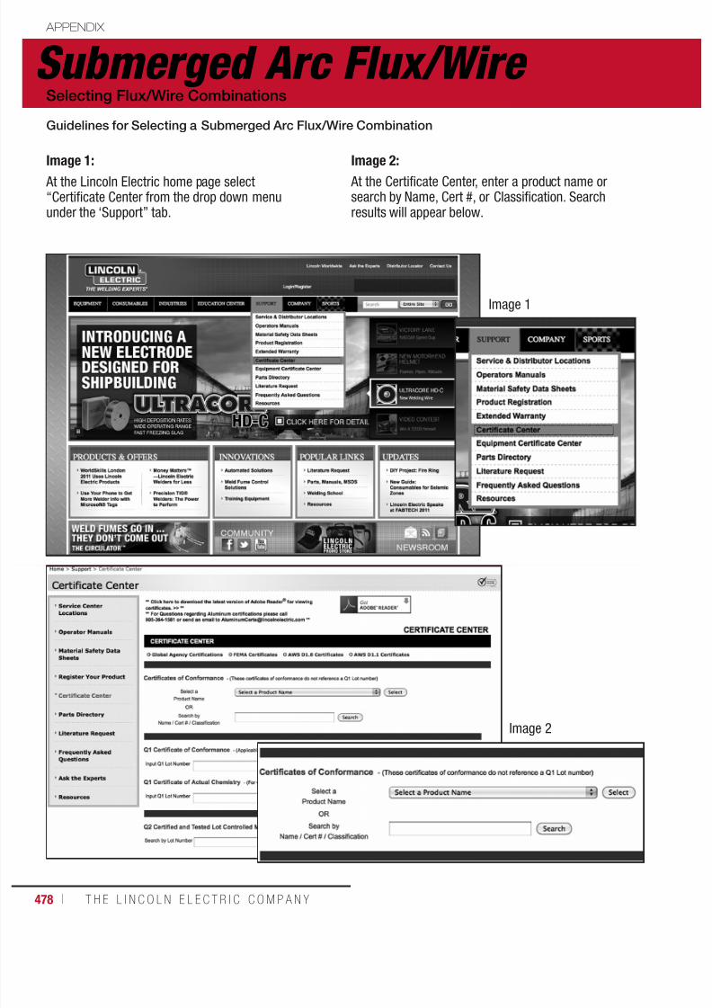
7/18/2019 c110 - Lincoln Electric Consumables 2014
http://slidepdf.com/reader/full/c110-lincoln-electric-consumables-2014 478/511478 ı T H E L I N C O L N E L E C T R I C C O M P A N Y
Submerged Arc Flux/Wire APPENDIX
Selecting Flux/Wire Combinations
Guidelines for Selecting a Submerged Arc Flux/Wire Combination
Image 1:
At the Lincoln Electric home page select“Certificate Center from the drop down menuunder the ‘Support” tab.
Image 1
Image 2
Image 2:
At the Certificate Center, enter a product name orsearch by Name, Cert #, or Classification. Searchresults will appear below.

7/18/2019 c110 - Lincoln Electric Consumables 2014
http://slidepdf.com/reader/full/c110-lincoln-electric-consumables-2014 479/511W E L D I N G C O N S U M A B L E S C A TA L O G ı 479
Hardfacing APPENDIX
Cross Checking
Special precautions should be taken with any build-up or hardfacing product on applications that are inherently
crack sensitive, such as high carbon or alloy steels, previously hardfaced parts, highly stressed parts, and workhardened parts. The hardfacing of heavy cylinders, massive parts and parts having complex shapes are allexamples of applications exhibiting high internal stresses that may result in delayed cracking.
These applications may require one or more of the following:
• Higher preheat temperatures
• Higher interpass temperatures
• Controlled slow cooling between passes and/or layers
• Stress relieving
• Minimizing layer thickness
The table below will help determine if special precautions need to be taken with specific Lincore® wires:
SPECIAL PRECAUTIONS
Product
Lincore® Products
55 55-G 65-O 60-O 30-S 32-S 35-S 40-S 42-S
Higher Preheat Temp.(1)
150°C - 260ºC (300°F - 500ºF)
200°C - 260ºC (400°F - 500ºF)
Higher Interpass Temp.200°C - 320ºC (400°F-600ºF)
Controlled Cooling Between Passes/Layers
Stress Relieving 430°C - 480ºC (800°F - 900ºF)(2)
Every 6.4 mm (1/4 in) Thickness of Deposit
Every 10-13 mm (3/8 - 1/2 in) Thickness of Deposit
Minimize Layer Thickness
(1)Preheat depends on the base material chemistry and thickness, as well as the weld metal chemistry.(2)Stress relieving in temperatures in excess of 482°C (900°F) will result in a “softening” of the deposit.
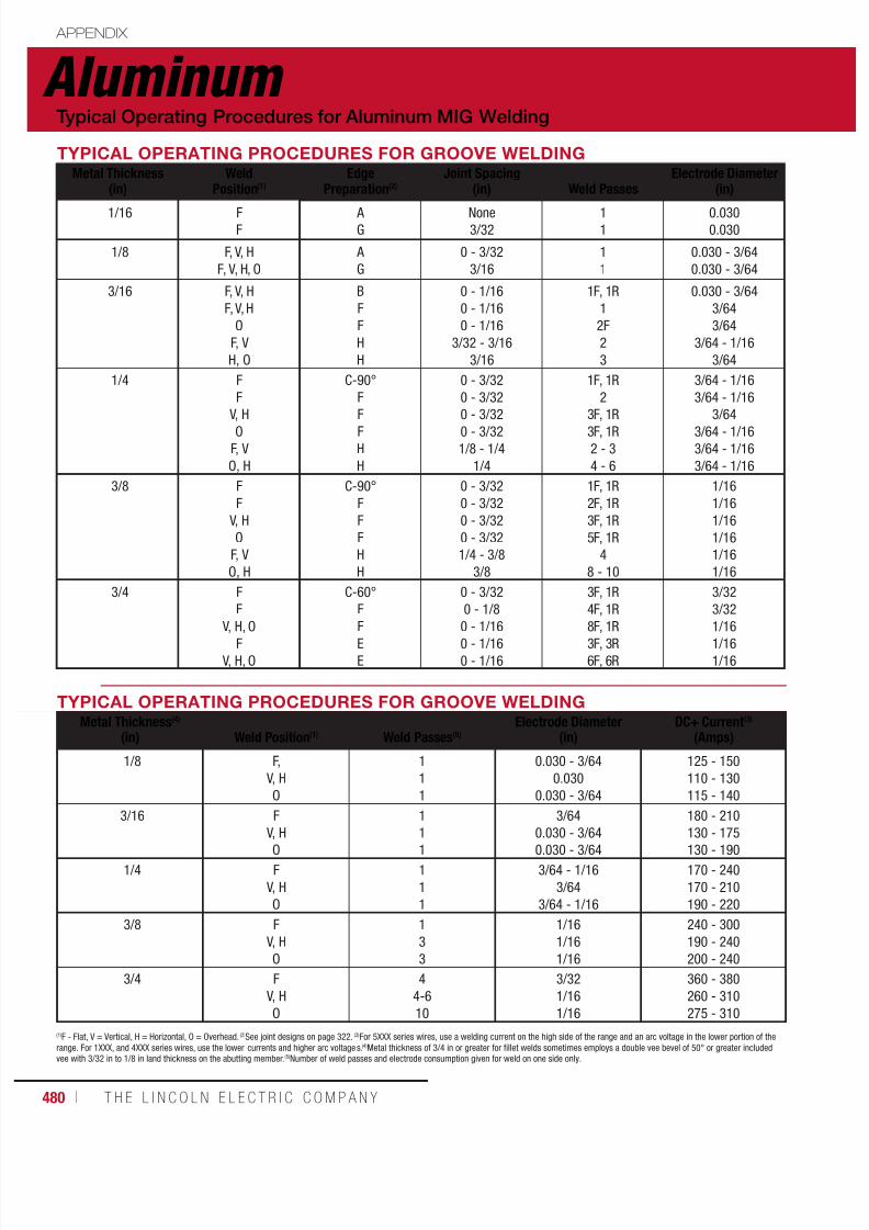
7/18/2019 c110 - Lincoln Electric Consumables 2014
http://slidepdf.com/reader/full/c110-lincoln-electric-consumables-2014 480/511480 ı T H E L I N C O L N E L E C T R I C C O M P A N Y
Aluminum APPENDIX
TYPICAL OPERATING PROCEDURES FOR GROOVE WELDINGMetal Thickness
(in)Weld
Position(1)Edge
Preparation(2)Joint Spacing
(in) Weld PassesElectrode Diameter
(in)
1/16 FF
A G
None3/32
11
0.0300.030
1/8 F, V, H
F, V, H, O
A
G
0 - 3/32
3/16
1
1
0.030 - 3/64
0.030 - 3/64
3/16 F, V, H
F, V, H
O
F, V
H, O
B
F
F
H
H
0 - 1/16
0 - 1/16
0 - 1/16
3/32 - 3/16
3/16
1F, 1R
1
2F
2
3
0.030 - 3/64
3/64
3/64
3/64 - 1/16
3/64
1/4 F
F
V, HO
F, V
O, H
C-90°
F
FF
H
H
0 - 3/32
0 - 3/32
0 - 3/320 - 3/32
1/8 - 1/4
1/4
1F, 1R
2
3F, 1R3F, 1R
2 - 3
4 - 6
3/64 - 1/16
3/64 - 1/16
3/643/64 - 1/16
3/64 - 1/16
3/64 - 1/16
3/8 F
F
V, H
O
F, V
O, H
C-90°
F
F
F
H
H
0 - 3/32
0 - 3/32
0 - 3/32
0 - 3/32
1/4 - 3/8
3/8
1F, 1R
2F, 1R
3F, 1R
5F, 1R
4
8 - 10
1/16
1/16
1/16
1/16
1/16
1/16
3/4 F
F
V, H, OF
V, H, O
C-60°
F
FE
E
0 - 3/32
0 - 1/8
0 - 1/160 - 1/16
0 - 1/16
3F, 1R
4F, 1R
8F, 1R3F, 3R
6F, 6R
3/32
3/32
1/161/16
1/16
Typical Operating Procedures for Aluminum MIG Welding
TYPICAL OPERATING PROCEDURES FOR GROOVE WELDINGMetal Thickness(4)
(in) Weld Position(1) Weld Passes(5)Electrode Diameter
(in)DC+ Current(3)
(Amps)
1/8 F,
V, H
O
1
1
1
0.030 - 3/64
0.030
0.030 - 3/64
125 - 150
110 - 130
115 - 140
3/16 F
V, H
O
1
1
1
3/64
0.030 - 3/64
0.030 - 3/64
180 - 210
130 - 175
130 - 190
1/4 F
V, H
O
1
1
1
3/64 - 1/16
3/64
3/64 - 1/16
170 - 240
170 - 210
190 - 220
3/8 F
V, H
O
1
3
3
1/16
1/16
1/16
240 - 300
190 - 240
200 - 240
3/4 F
V, H
O
4
4-6
10
3/32
1/16
1/16
360 - 380
260 - 310
275 - 310
(1)F - Flat, V = Vertical, H = Horizontal, O = Overhead. (2)See joint designs on page 322. (3)For 5XXX series wires, use a welding current on the high side of the range and an arc voltage in the lower portion of the
range. For 1XXX, and 4XXX series wires, use the lower currents and higher arc voltages.
(4)
Metal thickness of 3/4 in or greater for fillet welds sometimes employs a double vee bevel of 50° or greater includedvee with 3/32 in to 1/8 in land thickness on the abutting member. (5)Number of weld passes and electrode consumption given for weld on one side only.

7/18/2019 c110 - Lincoln Electric Consumables 2014
http://slidepdf.com/reader/full/c110-lincoln-electric-consumables-2014 481/511W E L D I N G C O N S U M A B L E S C A TA L O G ı 481
DC+ Current(3)
(Amps)Arc Votlage(3)
(Volts)Argon Gas Flow
(cfh)Arc Travel Speed
(ipm/pass)Approx. Electrode Consump.
(lb/100 ft)
70 - 11070 - 110
15 - 2015 - 20
2525
25 - 4525 - 45
1.52
120 - 150
110 - 135
20 - 24
19 - 23
30
30
24 - 30
18 - 28
2
3
130 - 175
140 - 180
140 - 175
140 - 185
130 - 175
22 - 26
23- 2 7
23 - 27
23 - 27
23 - 27
35
35
60
35
60
24 - 30
24 - 30
24 - 30
24 - 30
25 - 35
4
5
5
8
10
175 - 200
185 - 225
165 - 190180 - 200
175 - 225
170 - 200
24 - 28
24 - 29
25 - 2925 - 29
25 - 29
25 - 29
40
40
4560
40
60
24 - 30
24 - 30
25 - 3525 - 35
24 - 30
25 - 40
6
8
1010
12
12
225 - 290
210 - 275
190 - 220
200 - 250
210 - 290
190 - 260
26 - 29
26 - 29
26 - 29
26 - 29
26 - 29
26 - 29
50
50
55
80
50
80
20 - 30
24 - 35
24 - 30
25 - 40
24 - 30
25 - 40
16
18
20
20
35
50
340 - 400
325 - 375
240 - 300270 - 330
230 - 280
26 - 31
26 - 31
26 - 3026 - 30
26 - 30
60
60
8060
80
14 - 20
16 - 20
24 - 3016 - 24
16 - 24
50
70
7570
75
Aluminum APPENDIX
Typical Operating Procedures for Aluminum MIG Welding
Arc Votlage(3)
(Volts)Argon Gas Flow
(cfh)Arc Travel Speed
(ipm/pass)Approx. Electrode Consump.(5)
(lb/100 ft)
20 - 24
19 - 23
20 - 24
30
30
40
24 - 30
24 - 30
24 - 30
2
2
2
22 - 26
21 - 25
22 - 26
30
35
45
24 - 30
24 - 30
24 - 30
4.5
4.5
4.5
24 - 28
23 - 27
24 - 28
40
45
60
24 - 30
24 - 30
24 - 30
7
7
7
26 - 29
24 - 27
25 - 28
50
60
85
18 - 25
24 - 30
24 - 30
17
17
17
26 - 30
25 - 20
25 - 29
60
70
85
18 - 25
24 - 30
24 - 30
66
66
66

7/18/2019 c110 - Lincoln Electric Consumables 2014
http://slidepdf.com/reader/full/c110-lincoln-electric-consumables-2014 482/511482 ı T H E L I N C O L N E L E C T R I C C O M P A N Y
Aluminum APPENDIX
Typical Joint Designs for Aluminum MIG Welding
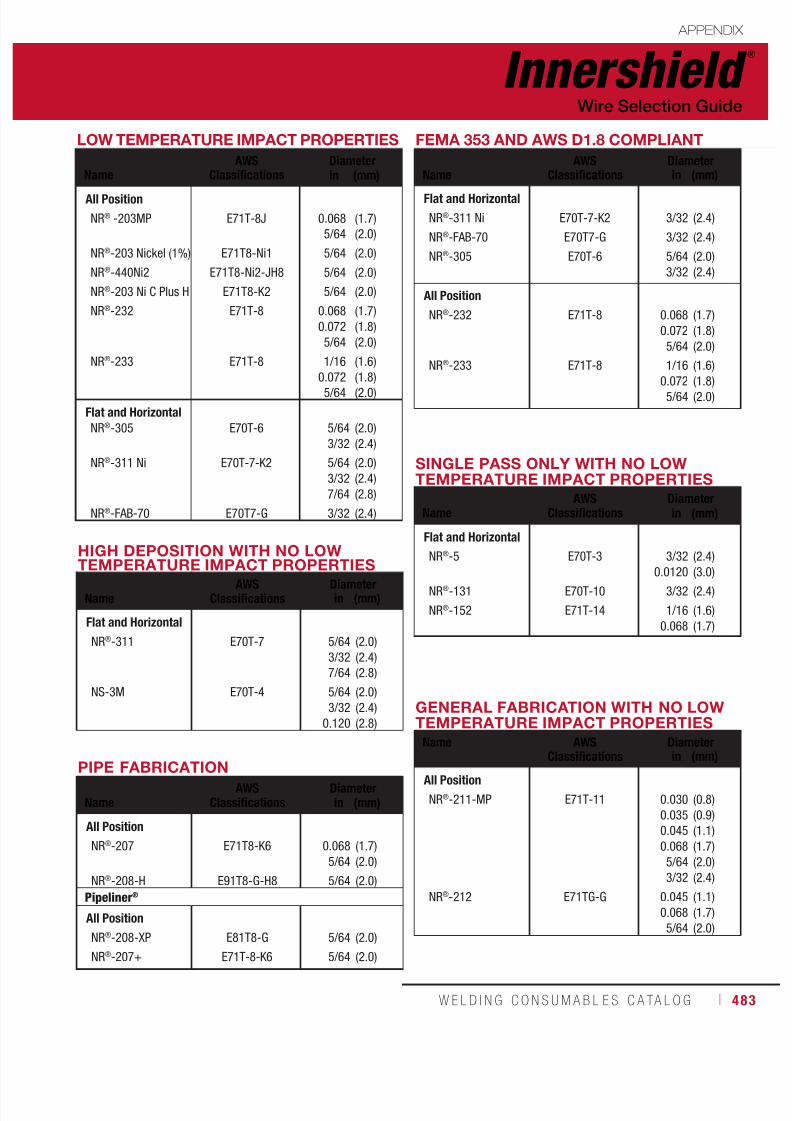
7/18/2019 c110 - Lincoln Electric Consumables 2014
http://slidepdf.com/reader/full/c110-lincoln-electric-consumables-2014 483/511W E L D I N G C O N S U M A B L E S C A TA L O G ı 483
Innershield ®
APPENDIX
Wire Selection Guide
LOW TEMPERATURE IMPACT PROPERTIES
NameAWS
ClassificationsDiameterin (mm)
All Position
NR® -203MP
NR®-203 Nickel (1%)
NR®-440Ni2
NR®-203 Ni C Plus H
NR®-232
NR®-233
E71T-8J
E71T8-Ni1
E71T8-Ni2-JH8
E71T8-K2
E71T-8
E71T-8
0.068
5/64
5/64
5/64
5/64
0.068
0.072
5/64
1/16
0.0725/64
(1.7)
(2.0)
(2.0)
(2.0)
(2.0)
(1.7)
(1.8)
(2.0)
(1.6)
(1.8)(2.0)
Flat and HorizontalNR®-305
NR®-311 Ni
NR®-FAB-70
E70T-6
E70T-7-K2
E70T7-G
5/64
3/32
5/64
3/32
7/64
3/32
(2.0)
(2.4)
(2.0)
(2.4)
(2.8)
(2.4)
HIGH DEPOSITION WITH NO LOWTEMPERATURE IMPACT PROPERTIES
NameAWS
ClassificationsDiameterin (mm)
Flat and Horizontal
NR®-311
NS-3M
E70T-7
E70T-4
5/64
3/32
7/64
5/64
3/32
0.120
(2.0)
(2.4)
(2.8)
(2.0)
(2.4)
(2.8)
SINGLE PASS ONLY WITH NO LOWTEMPERATURE IMPACT PROPERTIES
NameAWS
ClassificationsDiameterin (mm)
Flat and Horizontal
NR®-5
NR®-131
NR®-152
E70T-3
E70T-10
E71T-14
3/32
0.01203/32
1/16
0.068
(2.4)
(3.0)(2.4)
(1.6)
(1.7)
PIPE FABRICATION
NameAWS
ClassificationsDiameterin (mm)
All Position
NR®-207
NR®-208-H
E71T8-K6
E91T8-G-H8
0.068
5/64
5/64
(1.7)
(2.0)
(2.0)
Pipeliner®
All Position
NR®-208-XP
NR®
-207+
E81T8-G
E71T-8-K6
5/64
5/64
(2.0)
(2.0)
GENERAL FABRICATION WITH NO LOWTEMPERATURE IMPACT PROPERTIES
Name AWSClassifications
Diameterin (mm)
All Position
NR®-211-MP
NR®-212
E71T-11
E71TG-G
0.030
0.035
0.045
0.068
5/64
3/32
0.045
0.068
5/64
(0.8)
(0.9)
(1.1)
(1.7)
(2.0)
(2.4)
(1.1)
(1.7)
(2.0)
FEMA 353 AND AWS D1.8 COMPLIANT
NameAWS
ClassificationsDiameterin (mm)
Flat and Horizontal
NR®-311 Ni
NR®-FAB-70
NR®-305
E70T-7-K2
E70T7-G
E70T-6
3/32
3/32
5/64
3/32
(2.4)
(2.4)
(2.0)
(2.4)
All Position
NR®-232
NR®-233
E71T-8
E71T-8
0.068
0.072
5/64
1/16
0.0725/64
(1.7)
(1.8)
(2.0)
(1.6)
(1.8)(2.0)

7/18/2019 c110 - Lincoln Electric Consumables 2014
http://slidepdf.com/reader/full/c110-lincoln-electric-consumables-2014 484/511484 ı T H E L I N C O L N E L E C T R I C C O M P A N Y
POSITION OF WELDING, POLARITY AND APPLICATION REQUIREMENTS
AWSClassifications
WeldingPosition(1) Current Application(2)
E70T-3 H and F DC+ S
E70T-4 H and F DC+ M
E70T-6 H and F DC+ M
E70T-7 H and F DC- M
E71T-8 H, F, VU, OH DC- M
E70T-10 H and F DC- S
E71T-11 H, F, VD, OH DC- M
E71T-14 H, F, VD, OH DC- SE71T-G VU, OH Not Specified M
(1) H = Horizontal position
F = Flat position
OH = Overhead position
VU = Vertical-Up position
VD = Vertical-Down position(2) S = Single pass only
M = Single or Multiple pass
Innershield ®
APPENDIX
Wire Selection Guide
Structural Welding Code
Seismic Supplement
For everything you need to know about welding in seismic zones
To assist structural fabricators, erectors, inspectors and specifying engineers, Lincoln Electriccreated this D1.8 Resource Center with tools to understand seismic welding guidelines and
links to Lincoln Electric consumables tested to meet the AWS D1.8 and FEMA 353
requirements. The development of Lincoln Electric’s D1.8 Resource Center is just one more
way Lincoln sets the standard for the welding industry, worldwide.
www.lincolnelectric.com/d1.8

7/18/2019 c110 - Lincoln Electric Consumables 2014
http://slidepdf.com/reader/full/c110-lincoln-electric-consumables-2014 485/511W E L D I N G C O N S U M A B L E S C A TA L O G ı 485
Agency Approvals APPENDIX
Consumables Qualifications Guide
The notes and codes listed below are also repeated throughout the catalog where applicable.
• American Bureau of Shipping (ABS) approvals are issued subject to the Bureau’s Rule requirementfor Materials and Welding Part 2. Tests are conducted in the company’s plant, under supervision of an ABS surveyor to determine if electrodes conform to ABS grades or AWS specifications previously judgedsatisfactory by ABS for welding vessels. The Bureau publishes a list of approved electrodes givingtheir class and approved operating positions for each size. Sometimes, where there is no approvedspecification, approval may be given on the basis that each individual shipyard or contractor willqualify the procedure and electrode subject to Part 2, Section 3, paragraph 2/3C.3.2.c.
• American Society of Mechanical Engineers (ASME) has issued specifications covering constructionof nuclear facilities. Each lot of welding consumables to be used must be individually tested to ASMESFA specifications.
• American Welding Society (AWS) specifications and classifications are established by the Societyto provide standards for different types of electrodes throughout the industry. AWS does not test orapprove any electrodes. The manufacturer certifies that their electrode conforms to a certain class.
• Canadian Welding Bureau (CWB) approvals are based on tests witnessed by a CWB representative. Approvals listed in this booklet are for products manufactured in the USA. Products manufactured in
Canada are approved separately. In general, CWB specifications are similar to AWS specifications.Copies of approvals are maintained in Cleveland and are available upon request.
• Lloyd’s Register (LR), Det Norske Veritas (DNV), Germanischer Lloyd (GL), Bureau Veritas (BV),Controlas, and Nippon Kaiji Kyokai (NKK) issue approvals for electrodes used worldwide inshipbuilding, offshore structures and pressure vessels. Products approved under the rules of theseclassification societies require annual requalification under the supervision of their surveyors.
• TÜV (TUV) is a German agency very similar to ASME. Projects manufactured under TUV rules must bewelded with consumable approved by TUV. Initial approvals are obtained based on testing completed
under TUV supervision. Approvals are maintained subject to Quality Assurance audits completed everytwo years.
• Deutche Bahn (DB) is the approval agency for German railroads. Approvals are based on testsspecified by DB, and witnessed by an authorized third party.

7/18/2019 c110 - Lincoln Electric Consumables 2014
http://slidepdf.com/reader/full/c110-lincoln-electric-consumables-2014 486/511486 ı T H E L I N C O L N E L E C T R I C C O M P A N Y
PRODUCTAWSCode
AWS/ASMECLASS
ABSGrade
Lloyd'sRegisterGrade
DNVGrade
Stick Electrode
Fleetweld® 5P A5.1/A5.1M: 2004 E6010 E6010 3M -
Fleetweld® 5P+ A5.1/A5.1M: 2004 E6010 E6010 - -
Fleetweld® 180 A5.1/A5.1M: 2004 E6011 - - -
Fleetweld® 35 A5.1/A5.1M: 2004 E6011 E6011 3M -
Fleetweld® 35LS A5.1/A5.1M: 2004 E6011 - - -
Fleetweld® 37 A5.1/A5.1M: 2004 E6013 E6013 3M 1
Fleetweld®
22 A5.1/A5.1M: 2004 E6022 - - -Fleetweld® 47 A5.1/A5.1M: 2004 E7014 E7014 1M 1
Jetweld® 2 A5.1/A5.1M: 2004 E6027 E6027 3M 3
Jetweld® 1 A5.1/A5.1M: 2004 E7024-1 E7024-1 1M 1
Excalibur® 7018 MR® A5.1/A5.1M: 2004 E7018, E7018 H4R 3Y H5 3YM H5 3 YH5
Jetweld® LH-70 A5.1/A5.1M: 2004 E7018 H4R E7018, 3Y 3YM H5 3 Y40H5
Jet-LH® 78 MR® A5.1/A5.1M: 2004 E7018 H4R E7018 3YM H5 3 YH5
Lincoln® 7018AC A5.1/A5.1M: 2004 E7018 H8 - - -
Excalibur® 7018-1 MR® A5.1/A5.1M: 2004 E7018-1, E7018-1 H4R 3Y H5 3YM H5 3 YH5
Excalibur
®
7028 A5.1/A5.1M: 2004 E7028 H8
E7028, 3Y H10
(Fillet Only) 3YM H10 3 YH10Shield-Arc® HYP+ A5.5/A5.5M: 2006 E7010-P1, E7010-G E7010-P1 - -
Shield-Arc® 85 A5.5/A5.5M: 2006 E7010-A1 E7010-A1 - -
Shield-Arc® 70+ A5.5/A5.5M: 2006 E8010-G, E8010-P1 E8010-G - -
Shield-Arc® 90 A5.5/A5.5M: 2006 E9010-G - - -
Excalibur® 7018-A1 MR® A5.5/A5.5M: 2006 E7018-A1 H4R E7018-A1 H4R - -
Excalibur® 8018-B2 MR® A5.5/A5.5M: 2006 E8018-B2 H4R - - -
Excalibur® 8018-C1 MR® A5.5/A5.5M: 2006 E8018-C1 H4R - - -
Excalibur® 8018-C3 MR® A5.5/A5.5M: 2006 E8018-C3 H4R E8018-C3 H4R - -
Pipeliner® 18P A5.5/A5.5M: 2006 E8018-G, E8018-G H4 E8018-G - -
Excalibur® 9018-B3 MR® A5.5/A5.5M: 2006 E9018-B3 H4R - - -
Excalibur® 9018M MR® A5.5/A5.5M: 2006 E9018M H4R E9018M H4R - -
Excalibur® 10018-D2 MR® A5.5/A5.5M: 2006 E10018-D2 H4R 3YQ620 H5 3Y62 H5 3Y62 H5
Excalibur® 11018M MR® A5.5/A5.5M: 2006 E11018M H4R 4YQ690 H5 - 4 YM69 H5
Chromet® 1X A5.5 E8018-B2 H4 - - -
Chromet® 2X A5.5 E9018-B3 - - -
Chromet® 9-B9 A5.5 E9015-B9 - - -
Agency Approvals APPENDIX
NOTE: Approvals are updated periodically.
Consult your Lincoln Electric representative or the latest Approval/Grade revisions.
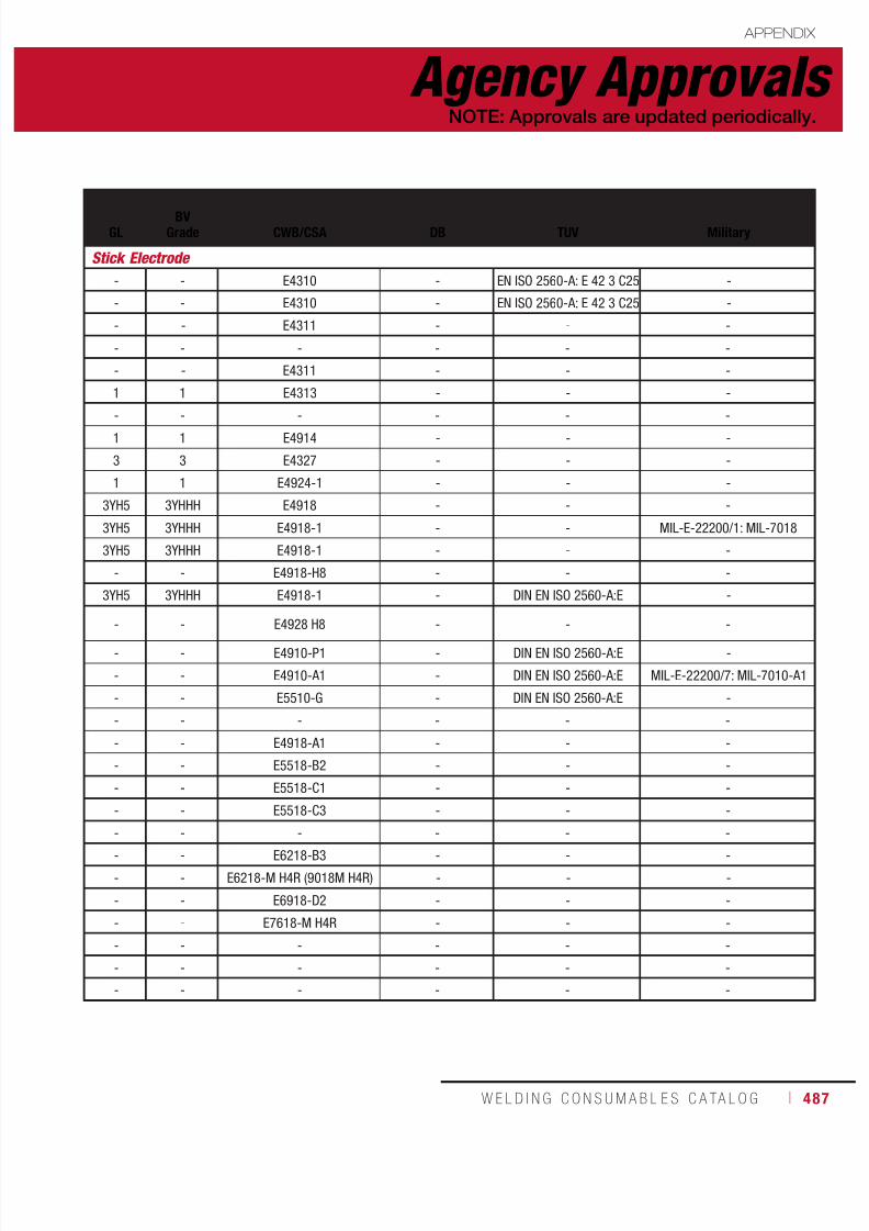
7/18/2019 c110 - Lincoln Electric Consumables 2014
http://slidepdf.com/reader/full/c110-lincoln-electric-consumables-2014 487/511W E L D I N G C O N S U M A B L E S C A TA L O G ı 487
GLBV
Grade CWB/CSA DB TUV Military
Stick Electrode
- - E4310 - EN ISO 2560-A: E 42 3 C25 -
- - E4310 - EN ISO 2560-A: E 42 3 C25 -
- - E4311 - - -
- - - - - -
- - E4311 - - -
1 1 E4313 - - -
- - - - - -1 1 E4914 - - -
3 3 E4327 - - -
1 1 E4924-1 - - -
3YH5 3YHHH E4918 - - -
3YH5 3YHHH E4918-1 - - MIL-E-22200/1: MIL-7018
3YH5 3YHHH E4918-1 - - -
- - E4918-H8 - - -
3YH5 3YHHH E4918-1 - DIN EN ISO 2560-A:E -
- - E4928 H8 - - -- - E4910-P1 - DIN EN ISO 2560-A:E -
- - E4910-A1 - DIN EN ISO 2560-A:E MIL-E-22200/7: MIL-7010-A1
- - E5510-G - DIN EN ISO 2560-A:E -
- - - - - -
- - E4918-A1 - - -
- - E5518-B2 - - -
- - E5518-C1 - - -
- - E5518-C3 - - -
- - - - - -
- - E6218-B3 - - -
- - E6218-M H4R (9018M H4R) - - -
- - E6918-D2 - - -
- - E7618-M H4R - - -
- - - - - -
- - - - - -
- - - - - -
Agency Approvals APPENDIX
NOTE: Approvals are updated periodically.
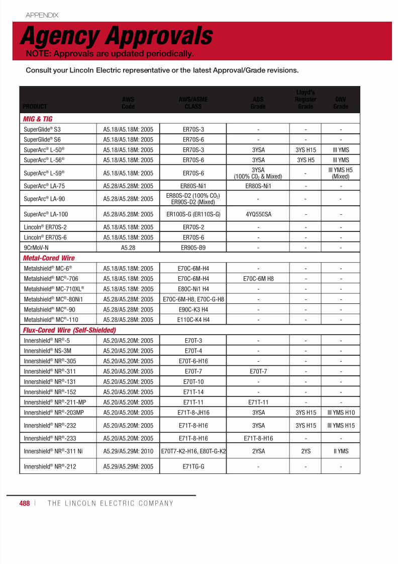
7/18/2019 c110 - Lincoln Electric Consumables 2014
http://slidepdf.com/reader/full/c110-lincoln-electric-consumables-2014 488/511488 ı T H E L I N C O L N E L E C T R I C C O M P A N Y
Agency Approvals APPENDIX
NOTE: Approvals are updated periodically.
Consult your Lincoln Electric representative or the latest Approval/Grade revisions.
PRODUCTAWSCode
AWS/ASMECLASS
ABSGrade
Lloyd'sRegisterGrade
DNVGrade
MIG & TIG
SuperGlide® S3 A5.18/A5.18M: 2005 ER70S-3 - - -
SuperGlide® S6 A5.18/A5.18M: 2005 ER70S-6 - - -
SuperArc® L-50® A5.18/A5.18M: 2005 ER70S-3 3YSA 3YS H15 III YMS
SuperArc® L-56® A5.18/A5.18M: 2005 ER70S-6 3YSA 3YS H5 III YMS
SuperArc® L-59® A5.18/A5.18M: 2005 ER70S-63YSA
(100% C02 & Mixed)-
III YMS H5(Mixed)
SuperArc® LA-75 A5.28/A5.28M: 2005 ER80S-Ni1 ER80S-Ni1 - -
SuperArc® LA-90 A5.28/A5.28M: 2005ER80S-D2 (100% CO2)
ER90S-D2 (Mixed)- - -
SuperArc® LA-100 A5.28/A5.28M: 2005 ER100S-G (ER110S-G) 4YQ550SA - -
Lincoln® ER70S-2 A5.18/A5.18M: 2005 ER70S-2 - - -
Lincoln® ER70S-6 A5.18/A5.18M: 2005 ER70S-6 - - -
9CrMoV-N A5.28 ER905-B9 - - -
Metal-Cored Wire
Metalshield® MC-6® A5.18/A5.18M: 2005 E70C-6M-H4 - - -
Metalshield® MC®-706 A5.18/A5.18M: 2005 E70C-6M-H4 E70C-6M H8 - -
Metalshield® MC-710XL® A5.18/A5.18M: 2005 E80C-Ni1 H4 - - -Metalshield® MC®-80Ni1 A5.28/A5.28M: 2005 E70C-6M-H8, E70C-G-H8 - - -
Metalshield® MC®-90 A5.28/A5.28M: 2005 E90C-K3 H4 - - -
Metalshield® MC®-110 A5.28/A5.28M: 2005 E110C-K4 H4 - - -
Flux-Cored Wire (Self-Shielded)
Innershield® NR®-5 A5.20/A5.20M: 2005 E70T-3 - - -
Innershield® NS-3M A5.20/A5.20M: 2005 E70T-4 - - -
Innershield® NR®-305 A5.20/A5.20M: 2005 E70T-6-H16 - - -
Innershield® NR®-311 A5.20/A5.20M: 2005 E70T-7 E70T-7 - -
Innershield® NR®-131 A5.20/A5.20M: 2005 E70T-10 - - -
Innershield® NR®-152 A5.20/A5.20M: 2005 E71T-14 - - -
Innershield® NR®-211-MP A5.20/A5.20M: 2005 E71T-11 E71T-11 - -
Innershield® NR®-203MP A5.20/A5.20M: 2005 E71T-8-JH16 3YSA 3YS H15 III YMS H10
Innershield® NR®-232 A5.20/A5.20M: 2005 E71T-8-H16 3YSA 3YS H15 III YMS H15
Innershield® NR®-233 A5.20/A5.20M: 2005 E71T-8-H16 E71T-8-H16 - -
Innershield® NR®-311 Ni A5.29/A5.29M: 2010 E70T7-K2-H16, E80T-G-K2 2YSA 2YS II YMS
Innershield® NR®-212 A5.29/A5.29M: 2005 E71TG-G - - -

7/18/2019 c110 - Lincoln Electric Consumables 2014
http://slidepdf.com/reader/full/c110-lincoln-electric-consumables-2014 489/511W E L D I N G C O N S U M A B L E S C A TA L O G ı 489
Agency Approvals APPENDIX
NOTE: Approvals are updated periodically.
GLBV
Grade CWB/CSA DB TUV Military
MIG & TIG
- - ER49S-3 - - -
- - ER49S-6 - - MIL-E-23765/1: MIL-70S-6
- - ER49S-3 - - MIL-E-23765/1: MIL-70S-3
- - ER49S-6 EN 440 G3Si1 EN 440 G3Si1 MIL-E-23765/1: MIL-70S-6
SA3YHHH(Mixed)
ER49S-6 - - -
- - ER55S-Ni1 (ER80S-Ni1) - - -
- -ER55S-D2 (ER80S-D2),ER62S-D2 (ER90S-D2)
- - MIL-E-23765/2: MIL-80S-3
- - ER69S-G (ER100S-G)EN 12534 T 69 5
Mn3Ni1, 5 Mo
EN 12534 T 69 5
Mn3Ni1, 5 Mo
MIL-E-23765/2:
MIL-100S-1
- - - - - -
- - - - - -
- - - - - -
Metal-Cored Wire
- - E491C-6MJ-H4 - - -
- - E492C-6MJ-H4 - - -
- - E491C-6M-H8 - - -- - E55C-Ni1 H4 (E80C-Ni1 H4) - - -
- - E62C-K3 H4 (E90C-K3 H4) - - -
- - E76C-K4 H4 (E110C-K4 H4) - - -
Flux-Cored Wire (Self-Shielded)
- - - - - -
- - E492T-4-H16 EN 758 T38 Z W N 3 - -
- - - - - -
- - E492T-7 - - -
- - - - - -
- - - - - -
- - E491T-11-H16 EN 758 T42 Z S N 1 EN 758 T42 A S N 1 -
3YH15S SA3YMH E491T-8 H16 - - -
3YH10S SA3YMH E491T-8 H16 EN 758 T42 3 Y N 2 EN 758 T42 3 Y N 2MIL-E-24403/1:
MIL-71T-8AS
- - - - - -
2YS SA2YM -EN 758 T42 2 1,
5Ni W N 5- -
- -E491TG-G-H16
(E71TG-G H16)- - -

7/18/2019 c110 - Lincoln Electric Consumables 2014
http://slidepdf.com/reader/full/c110-lincoln-electric-consumables-2014 490/511490 ı T H E L I N C O L N E L E C T R I C C O M P A N Y
Agency Approvals APPENDIX
NOTE: Approvals are updated periodically.
Consult your Lincoln Electric representative or the latest Approval/Grade revisions.
PRODUCTAWSCode
AWS/ASMECLASS
ABSGrade
Lloyd'sRegisterGrade
DNVGrade
Flux-Cored Wire (Gas-Shielded)
Innershield® NR®-203Nickel (1%)
A5.29/A5.29M: 2005 E71T8-Ni1-H16 3YSA 3YS H15 III YMS H10
Innershield® NR®-440Ni2 5.29/A5.29M: 2010 E71T8-Ni2-JH8 4YSAH10 4YS H10 IV YMS H10
Innershield® NR®-207 A5.29/A5.29M: 2005 E71T8-K6-H16 E71T-8-K6 - III YMS H15
Innershield® NR®-208-H A5.29/A5.29M: 2005 E91T8-G-H8 - - -
UltraCore® 71A85 A5.20/A5.20M: 2005 E71T-1M-H8, E71T-9M-H8 3YSA H10 3YS H10 III YMS H10
UltraCore® HD-M A5.20/A5.20M: 2005 E71T-1M-H8, E71T-9M-H8 3YSA H10 3YS H10 III YMS (H10)
UltraCore® 71C A5.20/A5.20M: 2005E71T-1C-H8,E71T-9C-H8
E71T-1C-H8,E71T-9C-H8
3YS H10 III YMS H10
UltraCore® HD-C A5.20/A5.20M: 2005 E71T-1C-H8, E71T-9C-H8 3YSA H10 3YS H10 III YMS H10
UltraCore® 71A75 Dual A5.20/A5.20M: 2005E71T-1C-H8, E71T-9C-H8,E71T-1M-H8, E71T-9M-H8
- - -
UltraCore® 712C A5.20/A5.20M: 2005E71T-1C-JH8, E71T-9C-
JH8, E71T-12C-JH83YSA H10 3YS H10 III YMS H10
UltraCore® 712A80 A5.20/A5.20M: 2005E71T-1M-JH8, E71T-9M-
JH8, E71T-12M-JH84YSA H10 4YS H10 IV YMS H10
UltraCore® 712A80-H A5.20/A5.20M: 2005E71T-1M-JH8, E71T-9M-
JH8, E71T-12M-JH84YSA H5 4YS H5 IV YMS H5
Outershield
®
71 Elite A5.20/A5.20M: 2005
E71T-1C-H8, E71T-9C-H8,
E71T-1M-H8, E71T-9M-H8 3SA, 3YSA H10 3YS H10 III YMS H10
Outershield® 71 Supreme A5.20/A5.20M: 2005E71T-1C-H4, E71T-1M-H4E71T-9C-H4, E71T-9M-H4
- - -
Outershield® 71M A5.20/A5.20M: 2005E71T-1C-J, E71T-9C-J,E71T-1M-J, E71T-9M-J
3YSA H15(1) 3YS H15 III YMS H10
UltraCore® 70C A5.20/A5.20M: 2005E70T-1C, E70T-1C-H8,E70T-9C, E70T-9C-H8
- - -
UltraCore® 75C A5.20/A5.20M: 2005 E70T-5C-JH4 - - II YMS H15
Outershield® 70 A5.20/A5.20M: 2005E70T-1C-H16,E70T-9C-H16
2YSA - II YMS H15
UltraCore® 81Ni1A75-H A5.29/A5.29M: 2005 E81T1-Ni1M-JH4 4YQ460SA H5 4Y46S H5 IV 46MS H5
UltraCore® 81Ni1C-H A5.29/A5.29M: 2005 E81T1-Ni1C-JH4 4YQ460SA H5 4Y46S H5 IV Y46MS H5
UltraCore® 81Ni2A75-H A5.29/A5.29M: 2005 E81T1-Ni2M-JH4 3YSA H5 3YS H5 III Y40MS H5
UltraCore® 81Ni2C-H A5.29/A5.29M: 2005 E81T1-Ni2C-JH4 3YSA H5 3YS H5 III Y40MS H5
UltraCore® 81K2A75-H A5.29/A5.29M: 2005 E81T1-K2M-JH4 4YQ460SA H5 4Y46S H5 IV 46MS H5
UltraCore® 81K2C-H A5.29/A5.29M: 2005 E81T1-K2C-JH4 4YQ460SA H5 4Y46S H5 IV 46MS H5
UltraCore® HD-12C A5.20/5.20M:E71T-1CJ, E71T-9CJ,
E71T-12CJ H8- - -
(1)Only for 0.045 in (1.1 mm), 0.052 in (1.3 mm) and 1/16 in. (1.6 mm) diameters.

7/18/2019 c110 - Lincoln Electric Consumables 2014
http://slidepdf.com/reader/full/c110-lincoln-electric-consumables-2014 491/511W E L D I N G C O N S U M A B L E S C A TA L O G ı 491
Agency Approvals APPENDIX
NOTE: Approvals are updated periodically.
Consult your Lincoln Electric representative or the latest Approval/Grade revisions.
GLBV
Grade CWB/CSA DB TUV Military
Flux-Cored Wire (Gas-Shielded)
- -E491T8-Ni1 H16(E71TG-G-H16)
EN 758 T42 3 1 Ni Y N
EN 758 T42 3 1 Ni Y N -
- - - - -
3YH15S SA3YMH - - - -
- - - - - -
- - E491T-9M H8 - - -
- - E491T-1M-H8, E491T-9M-H8 - - -
- - E491T-9 H8 - - -
- - E491T-9-H8 - - -
- -E491T-9 H8,
E491T-9M H8- - -
- -E491T-12J H8,E491T-9J H8
- - -
- -E491T-12MJ-H8,E491T-9MJ-H8
- - -
- -E491T-12MJ H4,E491T-9MJ H4
- - -
3YH10S - E491T-9-H8, E491T-9M-H8 - - -
- -E491T-9-H4,
E491T-9M-H4- - -
-SA3YH
(CO2 only)E491T-9,E491T-9M
- -MIL-E-24403/1: MIL-71T-1C,
MIL-71T-1M
- - E492T-9 H8 - - -
- - E492T-5J H4 - - -
- - E492T-9 H16 -EN 758 T 46 0 R C3 /
M3 H10MIL-E-24403/1: MIL-70T-1C
- -E551T1-Ni1M-JH4(E81T1-Ni1M-JH4)
- - -
- -E551T1-Ni1C-JH4(E81T1-Ni1C-JH4)
- - -
- -E551T1-Ni2M-JH4(E81T1-Ni2M-JH4)
- - -
- -E551T1-Ni2C-JH4(E81T1-Ni2C-JH4)
- - -
- - - - - -
- - - - - -
- - - - - -
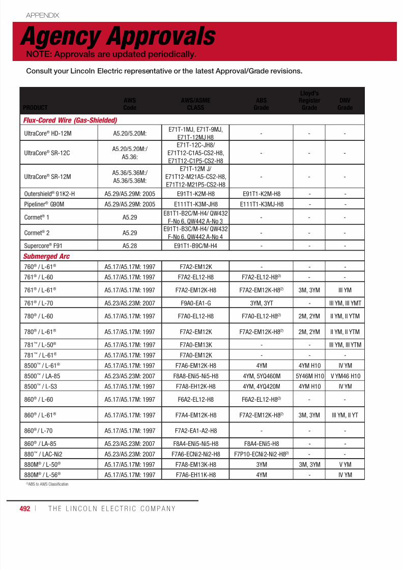
7/18/2019 c110 - Lincoln Electric Consumables 2014
http://slidepdf.com/reader/full/c110-lincoln-electric-consumables-2014 492/511492 ı T H E L I N C O L N E L E C T R I C C O M P A N Y
Agency Approvals APPENDIX
NOTE: Approvals are updated periodically.
Consult your Lincoln Electric representative or the latest Approval/Grade revisions.
(2) ABS to AWS Classification
PRODUCTAWSCode
AWS/ASMECLASS
ABSGrade
Lloyd'sRegisterGrade
DNVGrade
Flux-Cored Wire (Gas-Shielded)
UltraCore® HD-12M A5.20/5.20M:E71T-1MJ, E71T-9MJ,
E71T-12MJ H8- - -
UltraCore® SR-12C A5.20/5.20M:/
A5.36:
E71T-12C-JH8/
E71T12-C1A5-CS2-H8,
E71T12-C1P5-CS2-H8
- - -
UltraCore® SR-12M A5.36/5.36M:/
A5.36/5.36M:
E71T-12M J/
E71T12-M21A5-CS2-H8,
E71T12-M21P5-CS2-H8
- - -
Outershield®
91K2-H A5.29/A5.29M: 2005 E91T1-K2M-H8 E91T1-K2M-H8 - -Pipeliner® G90M A5.29/A5.29M: 2005 E111T1-K3M-JH8 E111T1-K3MJ-H8 - -
Cormet® 1 A5.29E81T1-B2C/M-H4/ QW432
F-No 6, QW442 A-No 3- - -
Cormet® 2 A5.29E91T1-B3C/M-H4/ QW432
F-No 6, QW442 A-No 4- - -
Supercore® F91 A5.28 E91T1-B9C/M-H4 - - -
Submerged Arc
760® / L-61® A5.17/A5.17M: 1997 F7A2-EM12K - - -
761® / L-60 A5.17/A5.17M: 1997 F7A2-EL12-H8 F7A2-EL12-H8(2) - -
761®
/ L-61®
A5.17/A5.17M: 1997 F7A2-EM12K-H8 F7A2-EM12K-H8(2)
3M, 3YM III YM
761® / L-70 A5.23/A5.23M: 2007 F9A0-EA1-G 3YM, 3YT - III YM, III YMT
780® / L-60 A5.17/A5.17M: 1997 F7A0-EL12-H8 F7A0-EL12-H8(2) 2M, 2YM II YM, II YTM
780® / L-61® A5.17/A5.17M: 1997 F7A2-EM12K F7A2-EM12K-H8(2) 2M, 2YM II YM, II YTM
781™ / L-50® A5.17/A5.17M: 1997 F7A0-EM13K - - III YM, III YTM
781™ / L-61® A5.17/A5.17M: 1997 F7A0-EM12K - - -
8500™ / L-61® A5.17/A5.17M: 1997 F7A6-EM12K-H8 4YM 4YM H10 IV YM
8500™ / LA-85 A5.23/A5.23M: 2007 F8A8-ENi5-Ni5-H8 4YM, 5YQ460M 5Y46M H10 V YM46 H10
8500™ / L-S3 A5.17/A5.17M: 1997 F7A8-EH12K-H8 4YM, 4YQ420M 4YM H10 IV YM
860® / L-60 A5.17/A5.17M: 1997 F6A2-EL12-H8 F6A2-EL12-H8(2) - -
860® / L-61® A5.17/A5.17M: 1997 F7A4-EM12K-H8 F7A2-EM12K-H8(2) 3M, 3YM III YM, II YT
860® / L-70 A5.17/A5.17M: 1997 F7A2-EA1-A2-H8 - - -
860® / LA-85 A5.23/A5.23M: 2007 F8A4-ENi5-Ni5-H8 F8A4-ENi5-H8 - -
880™ / LAC-Ni2 A5.23/A5.23M: 2007 F7A6-ECNi2-Ni2-H8 F7P10-ECNi2-Ni2-H8(2) - -
880M® / L-50® A5.17/A5.17M: 1997 F7A8-EM13K-H8 3YM 3M, 3YM V YM
880M® / L-56® A5.17/A5.17M: 1997 F7A6-EH11K-H8 4YM - IV YM

7/18/2019 c110 - Lincoln Electric Consumables 2014
http://slidepdf.com/reader/full/c110-lincoln-electric-consumables-2014 493/511W E L D I N G C O N S U M A B L E S C A TA L O G ı 493
Agency Approvals APPENDIX
NOTE: Approvals are updated periodically.
GLBV
Grade CWB/CSA DB TUV Military
Flux-Cored Wire (Gas-Shielded)
- - - - - -
- - - - - -
- - - - - -
- - - - - -- - - - - -
- - - - - -
- - - - - -
- - - - - -
Submerged Arc
- - - - - MIL-E-23765/4: MIL-F7A2-EM12
- - F49A3-EL12 - - -
3YM A3YM F49A3-EM12K-H8 - -
MIL-E-23765/4:
MIL-F7A2-EM12K
- - F62A2-EA1-G (F9A0-EA1-G) - - -
2YM, 2YTM - F49A2-EL12 - -MIL-E-23765/4:
MIL-F7A0-EL12
A2YTM F49A3-EM12K - -MIL-E-23765/4:
MIL-F7A2-EM12K
- - F49A2-EM13K - - -
- - F49A2-EM12K - - -
4YM - - - - -
4YM - - - - -
4YM - - - - -
- - - - -MIL-E-23765/4:
MIL-F6A2-EL12
3YM, 2YT A3YM, A2YT F49A4-EM12K - -MIL-E-23765/4:
MIL-F7A2-EM12K
- - - - -MIL-E-23765/4:
MIL-F7A2-EA1-A2
- - - - - -
- - - - - -
- - F49A5-EM13K - - -
- - - - - -
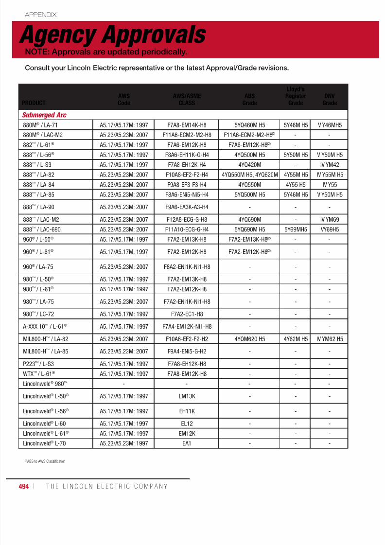
7/18/2019 c110 - Lincoln Electric Consumables 2014
http://slidepdf.com/reader/full/c110-lincoln-electric-consumables-2014 494/511494 ı T H E L I N C O L N E L E C T R I C C O M P A N Y
Agency Approvals APPENDIX
NOTE: Approvals are updated periodically.
Consult your Lincoln Electric representative or the latest Approval/Grade revisions.
PRODUCTAWSCode
AWS/ASMECLASS
ABSGrade
Lloyd'sRegisterGrade
DNVGrade
Submerged Arc
880M® / LA-71 A5.17/A5.17M: 1997 F7A8-EM14K-H8 5YQ460M H5 5Y46M H5 V Y46MH5
880M® / LAC-M2 A5.23/A5.23M: 2007 F11A6-ECM2-M2-H8 F11A6-ECM2-M2-H8(2) - -
882™ / L-61® A5.17/A5.17M: 1997 F7A6-EM12K-H8 F7A6-EM12K-H8(2) - -
888™ / L-56® A5.17/A5.17M: 1997 F8A6-EH11K-G-H4 4YQ500M H5 5Y50M H5 V Y50M H5
888™ / L-S3 A5.17/A5.17M: 1997 F7A8-EH12K-H4 4YQ420M - IV YM42
888™ / LA-82 A5.23/A5.23M: 2007 F10A8-EF2-F2-H4 4YQ550M H5, 4YQ620M 4Y55M H5 IV Y55M H5
888™
/ LA-84 A5.23/A5.23M: 2007 F9A8-EF3-F3-H4 4YQ550M 4Y55 H5 IV Y55888™ / LA-85 A5.23/A5.23M: 2007 F8A6-ENi5-Ni5-H4 5YQ500M H5 5Y46M H5 V Y50M H5
888™ / LA-90 A5.23/A5.23M: 2007 F9A6-EA3K-A3-H4 - - -
888™ / LAC-M2 A5.23/A5.23M: 2007 F12A8-ECG-G-H8 4YQ690M - IV YM69
888™ / LAC-690 A5.23/A5.23M: 2007 F11A10-ECG-G-H4 5YQ690M H5 5Y69MH5 VY69H5
960® / L-50® A5.17/A5.17M: 1997 F7A2-EM13K-H8 F7A2-EM13K-H8(2) - -
960® / L-61® A5.17/A5.17M: 1997 F7A2-EM12K-H8 F7A2-EM12K-H8(2) - -
960® / LA-75 A5.23/A5.23M: 2007 F8A2-ENi1K-Ni1-H8 - - -
980™ / L-50® A5.17/A5.17M: 1997 F7A2-EM13K-H8 - - -980™ / L-61® A5.17/A5.17M: 1997 F7A2-EM12K-H8 - - -
980™ / LA-75 A5.23/A5.23M: 2007 F7A2-ENi1K-Ni1-H8 - - -
980™ / LC-72 A5.17/A5.17M: 1997 F7A2-EC1-H8 - - -
A-XXX 10™ / L-61® A5.17/A5.17M: 1997 F7A4-EM12K-Ni1-H8 - - -
MIL800-H™ / LA-82 A5.23/A5.23M: 2007 F10A6-EF2-F2-H2 4YQM620 H5 4Y62M H5 IV YM62 H5
MIL800-H™ / LA-85 A5.23/A5.23M: 2007 F9A4-ENi5-G-H2 - - -
P223™ / L-S3 A5.17/A5.17M: 1997 F7A8-EH12K-H8 - - -
WTX™ / L-61® A5.17/A5.17M: 1997 F7A8-EM12K-H8 - - -
Lincolnweld® 980™ - - - - -
Lincolnweld® L-50® A5.17/A5.17M: 1997 EM13K - - -
Lincolnweld® L-56® A5.17/A5.17M: 1997 EH11K - - -
Lincolnweld® L-60 A5.17/A5.17M: 1997 EL12 - - -
Lincolnweld® L-61® A5.17/A5.17M: 1997 EM12K - - -
Lincolnweld® L-70 A5.23/A5.23M: 1997 EA1 - - -
(2) ABS to AWS Classification
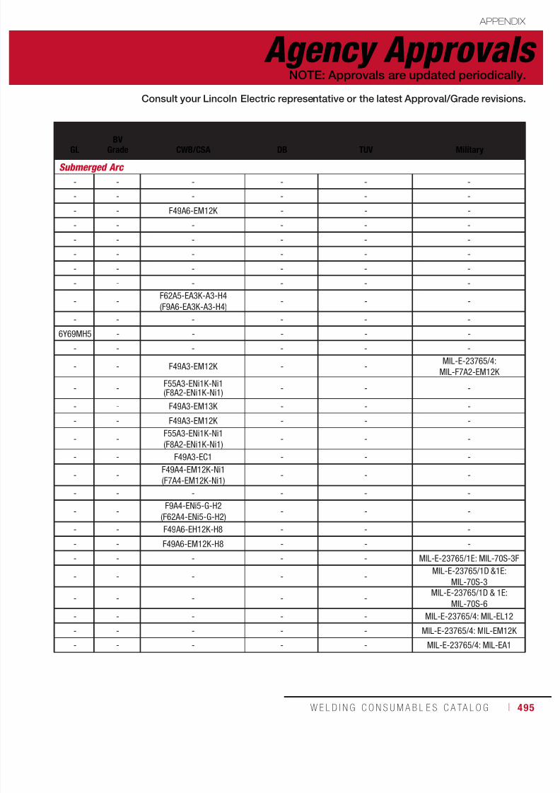
7/18/2019 c110 - Lincoln Electric Consumables 2014
http://slidepdf.com/reader/full/c110-lincoln-electric-consumables-2014 495/511W E L D I N G C O N S U M A B L E S C A TA L O G ı 495
Agency Approvals APPENDIX
NOTE: Approvals are updated periodically.
Consult your Lincoln Electric representative or the latest Approval/Grade revisions.
GLBV
Grade CWB/CSA DB TUV Military
Submerged Arc
- - - - - -
- - - - - -
- - F49A6-EM12K - - -
- - - - - -
- - - - - -
- - - - - -
- - - - - -- - - - - -
- -F62A5-EA3K-A3-H4
(F9A6-EA3K-A3-H4)- - -
- - - - - -
6Y69MH5 - - - - -
- - - - - -
- - F49A3-EM12K - -MIL-E-23765/4:
MIL-F7A2-EM12K
- -F55A3-ENi1K-Ni1(F8A2-ENi1K-Ni1)
- - -
- - F49A3-EM13K - - -- - F49A3-EM12K - - -
- -F55A3-ENi1K-Ni1
(F8A2-ENi1K-Ni1)- - -
- - F49A3-EC1 - - -
- -F49A4-EM12K-Ni1
(F7A4-EM12K-Ni1)- - -
- - - - - -
- -F9A4-ENi5-G-H2
(F62A4-ENi5-G-H2)- - -
- - F49A6-EH12K-H8 - - -
- - F49A6-EM12K-H8 - - -
- - - - - MIL-E-23765/1E: MIL-70S-3F
- - - - -MIL-E-23765/1D &1E:
MIL-70S-3
- - - - -MIL-E-23765/1D & 1E:
MIL-70S-6
- - - - - MIL-E-23765/4: MIL-EL12
- - - - - MIL-E-23765/4: MIL-EM12K
- - - - - MIL-E-23765/4: MIL-EA1

7/18/2019 c110 - Lincoln Electric Consumables 2014
http://slidepdf.com/reader/full/c110-lincoln-electric-consumables-2014 496/511496 ı T H E L I N C O L N E L E C T R I C C O M P A N Y
Agency Approvals APPENDIX
NOTE: Approvals are updated periodically.
Consult your Lincoln Electric representative or the latest Approval/Grade revisions.
PRODUCTAWSCode
AWS/ASMECLASS
ABSGrade
Lloyd'sRegisterGrade
DNVGrade
Submerged Arc
Lincolnweld® LA-100 A5.23/A5.23M: 1997 EM2 - - -
Lincolnweld® MIL800-H® - - - - -
Lincolnweld®
880™
- - - - -
Lincolnweld® 842-H™ A5.17/A5.17M: 1997,
A5.23/A5.23M:2011-
5YQM420 H5,
5YQM500 H5,
5YQM550 H5 (AC/DC+)
-
VYM42 H5,
VYM50 HD,
VYM55 H5 (AC/
DC+)
Stainless
Excalibur® 308/308L-15 A5.4/A5.4M: 2006 E308-15, E308L-15 E308-15, E308L-15 - -
Excalibur® 308L-16 A5.4/A5.4M: 2006 E308L-16 E308L-16 - -
Excalibur® 308/308H-16 A5.4/A5.4M: 2006 E308-16, E308H-16 E308-16, E308H-16 - -
Excalibur® 308/308L -17 A5.4/A5.4M: 2006 E308-17, E308L-17 - - -
Excalibur® 309/309L-15 A5.4/A5.4M: 2006 E309-15, E309L-15 E309-15, E309L-15 - -
Excalibur® 309/309L-16 A5.4/A5.4M: 2006 E309-16, E309L-16 E309-16, E309L-16 - -
Excalibur® 309/309L-17 A5.4/A5.4M: 2006 E309-17 / E309L-17 E309-17 / E309L-17 - -
Excalibur® 316/316L-15 A5.4/A5.4M: 2006 E316-15, E316L-15 E316-15, E316L-15 - -
Excalibur® 316/316L-16 A5.4/A5.4M: 2006 E316-16, E316L-16 E316-16, E316L-16 - -
Excalibur® 316/316L-17 A5.4/A5.4M: 2006 E316-17, E316L-17 - - -
Blue Max® MIG 308LSi A5.9/A5.9M: 2006 ER308Si/ ER308LSi ER308Si/ ER308LSi - -
Blue Max® MIG 309LSi A5.9/A5.9M: 2006 ER309Si/ ER309LSi ER309Si/ ER309LSi - -
Blue Max® MIG 316LSi A5.9/A5.9M: 2006 ER316Si/ ER316LSi ER316Si/ ER316LSi - -
Blue Max® LNM 307 - - - - -
Blue Max® LNM 347Si A5.9/A5.9M: 2006 ER347Si - - -
UltraCore® FC 308L A5.22/A5.22M: 1995E308LT0-1, E308LT0-4,E308T0-1, E308T0-4
E308LT0-1, E308LT0-4,E308T0-1, E308T0-4
- -
UltraCore® FCP 308L A5.22/A5.22M: 1995E308LT1-1, E308LT1-4,E308T1-1, E308T1-4
E308LT1-1, E308LT1-4,E308T1-1, E308T1-4
- -
UltraCore® FC 309L A5.22/A5.22M: 1995E309LT0-1, E309LT0-4,E309T0-1, E309T0-4
E309LT0-1, E309LT0-4,E309T0-1, E309T0-4
- -
UltraCore® FCP 309L A5.22/A5.22M: 1995E309LT1-1, E309LT1-4,E309T1-1, E309T1-4
E309LT1-1, E309LT1-4,E309T1-1, E309T1-4
- -
UltraCore® FC 316L A5.22/A5.22M: 1995E316LT0-1, E316LT0-4,
E316T0-1, E316T0-4
E316LT0-1, E316LT0-4,
E316T0-1, E316T0-4
- -

7/18/2019 c110 - Lincoln Electric Consumables 2014
http://slidepdf.com/reader/full/c110-lincoln-electric-consumables-2014 497/511W E L D I N G C O N S U M A B L E S C A TA L O G ı 497
Agency Approvals APPENDIX
NOTE: Approvals are updated periodically.
Consult your Lincoln Electric representative or the latest Approval/Grade revisions.
GLBV
Grade CWB/CSA DB TUV Military
Submerged Arc
- - - - -
MIL-E-23765/2D and /2E:MIL-100S-1 or MIL-100S-2
(with MIL800-H)NAVSEA Technical Publication
T9074-BC-GIB-010/0200
- - - - -
MIL-E-23765/2D & 2E:MIL-100S-2F or MIL-100S-1FNAVSEA Technical Publication
T9074-BC-GIB-010/0200
- - - - - -
- - -
ISO 26304-A-S 556 FB S3Ni1Mo, ISO
1417-A-S 50 6 FBSZ,ISO 1417-A-S 46 6
FB S3Si
ISO 26304-A-S 55 6 FB
S3Ni1Mo,
ISO 1417-A-S 50 6 FBSZ,
ISO 1417-A-S 46 6 FB S3Si
-
Stainless
- - - - - -
- - E308L-16 - - MIL-E-22200/2: MIL-308L-16
- - E308-16, E308H-16 - - MIL-E-22200/2: MIL-308-16
- - E308-17, E308L-17 - - -
- - - - - -
- - E309-16, E309L-16 - -MIL-E-22200/2: MIL-309-16,
MIL-309L-16
- - E309-17, E309L-17 - - -
- - E316-15, E316L-15 - - -
- - E316L-16 - -MIL-E-22200/2: MIL-316-16,
MIL-316L-16
- - E316-17, E316L-17 - - -
- - ER308LSi - - -
- - ER309LSi - - -
- - ER316LSi - - -
- - - - - -
- - - - - -
- - E308LT0-1, E308LT0-4 - - -
- - E308LT1-1, E308LT1-4 - - -
- - E309LT0-1, E309LT0-4 - - -
- - E309LT1-1, E309LT1-4 - - -
- - E316LT0-1, E316LT0-4 - - -

7/18/2019 c110 - Lincoln Electric Consumables 2014
http://slidepdf.com/reader/full/c110-lincoln-electric-consumables-2014 498/511498 ı T H E L I N C O L N E L E C T R I C C O M P A N Y
Agency Approvals APPENDIX
NOTE: Approvals are updated periodically.
Consult your Lincoln Electric representative or the latest Approval/Grade revisions.
PRODUCTAWSCode
AWS/ASMECLASS
ABSGrade
Lloyd'sRegisterGrade
DNVGrade
Stainless
UltraCore® FCP 316L A5.22/A5.22M: 1995E316LT1-1, E316LT1-4,E316T1-1, E316T1-4
E316LT1-1, E316LT1-4,E316T1-1, E316T1-4
- -
Blue Max® 308/308L A5.9/A5.9M: 2006 ER308, ER308L ER308, ER308L - -
Blue Max® 309/309L A5.9/A5.9M: 2006 ER309, ER309L ER309, ER309L - -
Blue Max® 316/316L A5.9/A5.9M: 2006 ER316, ER316L ER316, ER316L - -
Lincoln® ER308/308L A5.9/A5.9M: 2006 ER308, ER308L - - -
Lincoln® ER309/309L A5.9/A5.9M: 2006 ER309, ER309L - - -
Lincoln® ER316/316L A5.9/A5.9M: 2006 ER316, ER316L - - -
Outershield® MC-409 A5.9/A5.9M: 2006 EC 409 - - -
PRIMALLOY™ T-409Ti A5.9/A5.9M EC409 - - -
PRIMALLOY™ T-439Ti A5.9/A5.9M EC439 - - -
Tech-Rod® 308/308H A5.4/A5.4M: 2010 E308-16/308H-16 - - -
Tech-Rod® 308/308L A5.4/A5.4M: 2010 E308-16/308L-16 - - -
Tech-Rod® 309/309L A5.4/A5.4M: 2010 E309-16/309L-16 - - -
Tech-Rod® 310 A5.4/A5.4M: 2010 E310-16 - - -
Tech-Rod® 312 A5.4/A5.4M: 2010 E312-16 - - -
Tech-Rod® 316/316L A5.4/A5.4M: 2010 E316-16/E316L-16 - - -Tech-Rod® 317L A5.4/A5.4M: 2010 E317L-16 - - -
Tech-Rod® 320LR A5.4/A5.4M: 2010 E320LR-16 - - -
Tech-Rod® 330 A5.4/A5.4M: 2010 E330-16 - - -
Tech-Rod® 347 A5.4/A5.4M: 2010 E347-16 - - -
Tech-Rod® 385 A5.4/A5.4M: 2010 E385-16 - - -
Tech-Rod® 410 A5.4/A5.4M: 2010 E410-16 - - -
Tech-Rod® 410NiMo A5.4/A4.5M: 2010 E410NiMo-16 - - -
Tech-Rod® 2209 A5.4/A4.5M: 2010 E2209-16 - - -
Tech-Rod® 2594 A5.4/A4.5M: 2010 E2594-16 - - -
Tech-Rod® 630 A5.4/A4.5M: 2010 E630-16 - - -
Techalloy® 307 - - - - -
Techalloy® 308/308H A5.9/A5.9M: 2006 ER308H - - -
Techalloy® 308/308L A5.9/A5.9M: 2006 ER308L - - -
Techalloy® 308LHS A5.9 ER308LSi - - -
Techalloy® 309/309L A5.9/A5.9M: 2006 ER309L - - -
Techalloy® 309LHS A5.9/A5.9M: 2006 ER309LSi - - -
Techalloy® 309LMo A5.9/A5.9M: 2006 ER309LMo - - -
Techalloy® 310 A5.9/A5.9M: 2006 ER310 - - -

7/18/2019 c110 - Lincoln Electric Consumables 2014
http://slidepdf.com/reader/full/c110-lincoln-electric-consumables-2014 499/511W E L D I N G C O N S U M A B L E S C A TA L O G ı 499
Agency Approvals APPENDIX
NOTE: Approvals are updated periodically.
Consult your Lincoln Electric representative or the latest Approval/Grade revisions.
GLBV
Grade CWB/CSA DB TUV Military
Stainless
- - E316LT1-1, E316LT1-4 - - -
- - ER308L - - -
- - ER309L - - -
- - ER316L - - -
- - - - - -
- - - - - -
- - - - - -
- - EC409 - - -
- - - - - -
- - - - - -
- - - - - -
- - - - - -
- - - - - -
- - - - - -
- - - - - -
- - - - - -- - - - - -
- - - - - -
- - - - - -
- - - - - -
- - - - - -
- - - - - -
- - - - - -
- - - - - -
- - - - - -
- - - - - -
- - - - - -
- - - - - -
- - - - - -
- - - - - -
- - - - - -
- - - - - -
- - - - - -
- - - - - -

7/18/2019 c110 - Lincoln Electric Consumables 2014
http://slidepdf.com/reader/full/c110-lincoln-electric-consumables-2014 500/511500 ı T H E L I N C O L N E L E C T R I C C O M P A N Y
Agency Approvals APPENDIX
NOTE: Approvals are updated periodically.
Consult your Lincoln Electric representative or the latest Approval/Grade revisions.
PRODUCTAWSCode
AWS/ASMECLASS
ABSGrade
Lloyd'sRegisterGrade
DNVGrade
Stainless
Techalloy® 312 A5.9/A5.9M: 2006 ER312 - - -
Techalloy® 316/316L A5.9/A5.9M: 2006 ER316L - - -
Techalloy® 316LHS A5.9/A5.9M: 2006 ER316LSi - - -
Techalloy® 317L A5.9/A5.9M: 2006 ER317L - - -
Techalloy® 320LR A5.9/A5.9M: 2006 ER320LR - - -
Techalloy® 330 A5.9/A5.9M: 2006 ER330 - - -
Techalloy®
347 A5.9/A5.9M: 2006 ER347 - - -Techalloy® 385 A5.9/A5.9M: 2006 ER385 - - -
Techalloy® 409Nb A5.9/A5.9M: 2006 ER409Nb - - -
Techalloy® 410 A5.9/A5.9M: 2006 ER410 - - -
Techalloy® 410NiMo A5.9/A5.9M: 2006 ER410NiMo - - -
Techalloy® 630 A5.9/A5.9M: 2006 ER630 - - -
Techalloy® 2209 A5.9/A5.9M: 2006 ER2209 - - -
Techalloy® 2594 A5.9/A5.9M: 2006 ER2594 - - -
Supercore® 347 A5.28 E347T0-1/4 - - -
Supercore® 2205P A5.22 E2209T1-1/4 - - -
Cast Iron
Softweld® 55Ni A5.15: 1990 ENiFe-CI - - -
Softweld® 99Ni A5.15: 1990 ENi-CI - - -
Ferroweld® A5.15: 1990 ESt - - -
Aluminum
SuperGlaze® 4043 A5.10/A5.10M: 1999 ER4043 - - -
SuperGlaze® 4047 A5.10/A5.10M: 1999 ER4047 - - -
SuperGlaze® 5183 A5.10/A5.10M: 1999 ER5183 IACS W26 Grade WC WC/I-1 S 5183
SuperGlaze® 5356 A5.10/A5.10M: 1999 ER5356 IACS W26 Grade WB WB/I-1 S 5356
SuperGlaze® 5356 TM™ A5.10/A5.10M: 1999 ER5356 - - -
SuperGlaze® 5554 A5.10/A5.10M: 1999 ER5554 - - -
SuperGlaze® 5556 A5.10/A5.10M: 1999 ER5556 IACS W26 Grade WC - -
SuperGlaze® 4043 A5.10/A5.10M: 1999 ER4043 - - -
SuperGlaze® 5356 A5.10/A5.10M: 1999 ER5356 - - -
Nickel
Supercore® 625P A5.34/A5.34M ENiCrMo3T1-4 - - -
Tech-Rod® 55 A5.15/A5.15M: 1990 ENiFe-Cl/ QSC-395 - - -
Tech-Rod® 99 A5.15/A5.15M: 1990 ENi-Cl/ QSC-395 - - -
Tech-Rod
®
112 A5.11/A5.11M: 2010 ENiCrMo-3/ QSC-395 - - -

7/18/2019 c110 - Lincoln Electric Consumables 2014
http://slidepdf.com/reader/full/c110-lincoln-electric-consumables-2014 501/511W E L D I N G C O N S U M A B L E S C A TA L O G ı 501
Agency Approvals APPENDIX
NOTE: Approvals are updated periodically.
Consult your Lincoln Electric representative or the latest Approval/Grade revisions.
GLBV
Grade CWB/CSA DB TUV Military
Stainless
- - - - - -
- - - - - -
- - - - - -
- - - - - -
- - - - - -
- - - - - -
- - - - - -- - - - - -
- - - - - -
- - - - - -
- - - - - -
- - - - - -
- - - - - -
- - - - - -
- - - - - -
- - - - - -
Cast Iron
- - - - - -
- - - - - -
- - - - - -
Aluminum
- - ER4043 - - -
- - - - - -
RAIMg4,5 WC ER5183 - - -
RAIMg4 WB ER5356 - - -
- - ER5356 - - -
- - ER5554 - - -
- - - - - -
- - - - - -
- - - - - -
Nickel
- - - - - -
- - - - - -
- - - - - -
- - - - - -

7/18/2019 c110 - Lincoln Electric Consumables 2014
http://slidepdf.com/reader/full/c110-lincoln-electric-consumables-2014 502/511502 ı T H E L I N C O L N E L E C T R I C C O M P A N Y
Agency Approvals APPENDIX
NOTE: Approvals are updated periodically.
Consult your Lincoln Electric representative or the latest Approval/Grade revisions.
PRODUCTAWSCode
AWS/ASMECLASS
ABSGrade
Lloyd'sRegisterGrade
DNVGrade
Nickel
Tech-Rod® 112LFe A5.11/A5.11: 2010 ENiCrMo-3/ QSC-395 - - -
Tech-Rod® 117 A5.11/A5.11M: 2010ENiCrCoMo-1/
SFA-A5.4 ENiCrCoMo-1- - -
Tech-Rod® 122 A5.11/A5.11M: 2010ENiCrMo-10/
SFA-A5.4 ENiCrMo-10- - -
Tech-Rod® 141 A5.11/A5.11M: 2010 ENi-1/ SFA-A5.4 ENi-1 - - -
Tech-Rod® 182 A5.11/A5.11M: 2010ENiCrFe-3/
SFA-A5.4 ENiCrFe-3- - -
Tech-Rod® 187 A5.6/A5.6M: 2008 ECuNi/ SFA-A5.4 ECuNi - - -
Tech-Rod® 190 A5.11/A5.11M: 2010 ENiCu-7/ SFA-A5.4 ENiCu-7 - - -
Tech-Rod® 276 A5.11/A5.11M: 2010ENiCrMo-4/
SFA-A5.4 ENiCrMo-4- - -
Tech-Rod® Weld A A5.11/A5.11M: 2010 ENiCrFe-2/ QSC-395 - - -
Techalloy® 55 A5.15/A5.15M: 1990 ENiFe-CI - - -
Techalloy® 99 A5.15/A5.15M: 1990 ERNi-CI - - -
Techalloy® 208 A5.14 ERNi-1 - - -
Techalloy® 276 A5.14 ERNiCrMo-4 - - -
Techalloy® 413 A5.7 ERCuNi - - -
Techalloy® 418 A5.14 ERNiCu-7 - - -
Techalloy® 606 A5.14 ERNiCr-3 - - -
Techalloy® 617 A5.14 ERNiCrCoMo-1 - - -
Techalloy® 622 A5.14 ERNiCrMo-10 - - -
Techalloy® 625 A5.14 ERNiCrMo-3 - - -
Techalloy® 718 A5.14 ERNiFeCr-2 - - -
Techalloy® 825 A5.14 ERNiFeCr-1 - - -
7/18/2019 c110 - Lincoln Electric Consumables 2014
http://slidepdf.com/reader/full/c110-lincoln-electric-consumables-2014 503/511W E L D I N G C O N S U M A B L E S C A TA L O G ı 503
Agency Approvals APPENDIX
NOTE: Approvals are updated periodically.
Consult your Lincoln Electric representative or the latest Approval/Grade revisions.
GLBV
Grade CWB/CSA DB TUV Military
Nickel
- - - - - -
- - - - - -
- - - - - -
- - - - - -
- - - - - -
- - - - - -
- - - - - -
- - - - - -
- - - - - -
- - - - - -
- - - - - -
- - - - - -
- - - - - -
- - - - - -
- - - - - -
- - - - - -
- - - - - -
- - - - - -
- - - - - -
- - - - - -
- - - - - -
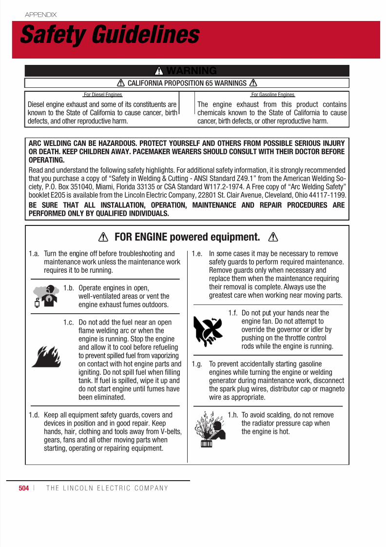
7/18/2019 c110 - Lincoln Electric Consumables 2014
http://slidepdf.com/reader/full/c110-lincoln-electric-consumables-2014 504/511504 ı T H E L I N C O L N E L E C T R I C C O M P A N Y
Safety Guidelines APPENDIX
WARNINGCALIFORNIA PROPOSITION 65 WARNINGS
Diesel engine exhaust and some of its constituents areknown to the State of California to cause cancer, birthdefects, and other reproductive harm.
The engine exhaust from this product containschemicals known to the State of California to causecancer, birth defects, or other reproductive harm.
ARC WELDING CAN BE HAZARDOUS. PROTECT YOURSELF AND OTHERS FROM POSSIBLE SERIOUS INJURYOR DEATH. KEEP CHILDREN AWAY. PACEMAKER WEARERS SHOULD CONSULT WITH THEIR DOCTOR BEFOREOPERATING.Read and understand the following safety highlights. For additional safety information, it is strongly recommendedthat you purchase a copy of “Safety in Welding & Cutting - ANSI Standard Z49.1” from the American Welding So-
ciety, P.O. Box 351040, Miami, Florida 33135 or CSA Standard W117.2-1974. A Free copy of “Arc Welding Safety”booklet E205 is available from the Lincoln Electric Company, 22801 St. Clair Avenue, Cleveland, Ohio 44117-1199.
BE SURE THAT ALL INSTALLATION, OPERATION, MAINTENANCE AND REPAIR PROCEDURES AREPERFORMED ONLY BY QUALIFIED INDIVIDUALS.
For Diesel Engines For Gasoline Engines
1.a. Turn the engine off before troubleshooting andmaintenance work unless the maintenance workrequires it to be running.
1.b. Operate engines in open,well-ventilated areas or vent theengine exhaust fumes outdoors.
1.c. Do not add the fuel near an openflame welding arc or when theengine is running. Stop the engineand allow it to cool before refuelingto prevent spilled fuel from vaporizingon contact with hot engine parts and
igniting. Do not spill fuel when fillingtank. If fuel is spilled, wipe it up anddo not start engine until fumes havebeen eliminated.
1.d. Keep all equipment safety guards, covers anddevices in position and in good repair. Keephands, hair, clothing and tools away from V-belts,gears, fans and all other moving parts whenstarting, operating or repairing equipment.
1.e. In some cases it may be necessary to removesafety guards to perform required maintenance.Remove guards only when necessary and
replace them when the maintenance requiringtheir removal is complete. Always use thegreatest care when working near moving parts.
1.f. Do not put your hands near theengine fan. Do not attempt tooverride the governor or idler bypushing on the throttle controlrods while the engine is running.
1.g. To prevent accidentally starting gasoline
engines while turning the engine or weldinggenerator during maintenance work, disconnectthe spark plug wires, distributor cap or magnetowire as appropriate.
1.h. To avoid scalding, do not removethe radiator pressure cap whenthe engine is hot.
FOR ENGINE powered equipment.

7/18/2019 c110 - Lincoln Electric Consumables 2014
http://slidepdf.com/reader/full/c110-lincoln-electric-consumables-2014 505/511W E L D I N G C O N S U M A B L E S C A TA L O G ı 505
APPENDIX
Safety Guidelines
2.a. Electric current flowing through any conductorcauses localized Electric and Magnetic Fields(EMF). Welding current creates EMF fields aroundwelding cables and welding machines
2.b. EMF fields may interfere with some pacemakers,and welders having a pacemaker should consult
their physician before welding.
2.c. Exposure to EMF fields in welding may have otherhealth effects which are now not known.
2.d. All welders should use the following proceduresin order to minimize exposure to EMF fields fromthe welding circuit:
2.d.1. Route the electrode and work cablestogether - Secure them with tape whenpossible.
2.d.2. Never coil the electrode lead aroundyour body.
2.d.3. Do not place your body between theelectrode and work cables. If the electrodecable is on your right side, the work cableshould also be on your right side.
2.d.4. Connect the work cable to the workpieceas close as possible to the area beingwelded.
2.d.5. Do not work next to welding power source.
ELECTRIC AND
MAGNETIC FIELDSmay be dangerous
3.a. The electrode and work (orground) circuits are electrically
“hot” when the welder is on. Donot touch these “hot” parts withyour bare skin or wet clothing.Wear dry, hole-free gloves toinsulate hands.
3.b. Insulate yourself from work and ground usingdry insulation. Make certain the insulation is largeenough to cover your full area of physical contactwith work and ground.In addition to the normal safety precautions, if
welding must be performed under electricallyhazardous conditions (in damp locations or whilewearing wet clothing; on metal structures suchas floors, gratings or scaffolds; when in crampedpositions such as sitting, kneeling or lying, if thereis a high risk of unavoidable or accidental contactwith the workpiece or ground) use the followingequipment:• Semiautomatic DC Constant Voltage (Wire) Welder.• DC Manual (Stick) Welder.• AC Welder with Reduced Voltage Control.
3.c. In semiautomatic or automatic wire welding, theelectrode, electrode reel, welding head, nozzle orsemiautomatic welding gun are also electrically“hot”.
3.d. Always be sure the work cable makes a good
electrical connection with the metal being welded.The connection should be as close as possible tothe area being welded.
3.e. Ground the work or metal to be welded to a goodelectrical (earth) ground.
3.f. Maintain the electrode holder, work clamp, weldingcable and welding machine in good, safe operatingcondition. Replace damaged insulation.
3.g. Never dip the electrode in water for cooling.
3.h. Never simultaneously touch electrically “hot”parts of electrode holders connected to two weldersbecause voltage between the two can be the totalof the open circuit voltage of both welders.
3.i. When working above floor level, use a safetybelt to protect yourself from a fall should you geta shock.
3.j. Also see Items 6.c. and 8.
ELECTRIC SHOCKcan kill.

7/18/2019 c110 - Lincoln Electric Consumables 2014
http://slidepdf.com/reader/full/c110-lincoln-electric-consumables-2014 506/511506 ı T H E L I N C O L N E L E C T R I C C O M P A N Y
5.a. Welding may produce fumes and gases hazardousto health. Avoid breathing these fumes and gases.When welding, keep your head out of the fume.Use enough ventilation and/or exhaust at the arcto keep fumes and gases away from the breathingzone. When welding with electrodes which
require special ventilation such as stainless orhard facing (see instructions on container orMSDS) or on lead or cadmium plated steel andother metals or coatings which produce highlytoxic fumes, keep exposure as low as possibleand within applicable OSHA PEL and ACGIH TLVlimits using local exhaust or mechanicalventilation. In confined spaces or in somecircumstances, outdoors, a respirator may berequired. Additional precautions are also requiredwhen welding on galvanized steel.
5.b. The operation of welding fume control equipmentis affected by various factors including proper useand positioning of the equipment, maintenance of
the equipment and the specific welding procedureand application involved. Worker exposure level
should be checked upon installation andperiodically thereafter to be certain it is withinapplicable OSHA PEL and ACGIH TLV limits.
5.c. Do not weld in locations near chlorinatedhydrocarbon vapors coming from degreasing,cleaning or spraying operations. The heat andrays of the arc can react with solvent vapors toform phosgene, a highly toxic gas, and otherirritating products.
5.d. Shielding gases used for arc welding can displaceair and cause injury or death. Always use enoughventilation, especially in confined areas, to insurebreathing air is safe.
5.e. Read and understand the manufacturer’sinstructions for this equipment and theconsumables to be used, including the materialsafety data sheet (MSDS) and follow youremployer’s safety practices. MSDS forms areavailable from your welding distributor or from
the manufacturer.
5.f. Also see item 1.b.
APPENDIX
Safety Guidelines
4.a. Use a shield with the proper filter and cover platesto protect your eyes from sparks and the rays ofthe arc when welding or observing open arcwelding. Headshield and filter lens shouldconform to ANSI Z87. I standards.
4.b. Use suitable clothing made from durableflame-resistant material to protect your skin
and that of your helpers from the arc rays.
4.c. Protect other nearby personnel with suitable,non-flammable screening and/or warn them notto watch the arc nor expose themselves to thearc rays or to hot spatter or metal.
ARC RAYS
can burn.
FUMES ANDGASES canbe dangerous.

7/18/2019 c110 - Lincoln Electric Consumables 2014
http://slidepdf.com/reader/full/c110-lincoln-electric-consumables-2014 507/511W E L D I N G C O N S U M A B L E S C A TA L O G ı 507
APPENDIX
Safety Guidelines
6.a. Remove fire hazards from the welding area. Ifthis is not possible, cover them to prevent thewelding sparks from starting a fire. Rememberthat welding sparks and hot materials fromwelding can easily go through small cracksand openings to adjacent areas. Avoid welding
near hydraulic lines. Have a fire extinguisherreadily available.
6.b. Where compressed gases are to be used at the job site, special precautions should be used toprevent hazardous situations. Refer to “Safetyin Welding and Cutting” (ANSI Standard Z49.1)and the operating information for the equipmentbeing used.
6.c. When not welding, make certain no part of the
electrode circuit is touching the work or ground. Accidental contact can cause overheating andcreate a fire hazard.
6.d. Do not heat, cut or weld tanks, drums orcontainers until the proper steps have beentaken to insure that such procedures will notcause flammable or toxic vapors from substancesinside. They can cause an explosion even thoughthey have been “cleaned”. For information,purchase “Recommended Safe Practices for the
Preparation for Welding and Cutting of Containers
and Piping That Have Held Hazardous Substances”, AWS F4.1 from the American Welding Society
(see address above).
6.e. Vent hollow castings or containers beforeheating, cutting or welding. They may explode.
6.f. Sparks and spatter are thrown from the weldingarc. Wear oil free protective garments such asleather gloves, heavy shirt, cuffless trousers,high shoes and a cap over your hair. Wear earplugs when welding out of position or in confinedplaces. Always wear safety glasses with side
shields when in a welding area.
6.g. Connect the work cable to the work as close tothe welding area as practical. Work cablesconnected to the building framework or otherlocations away from the welding area increasethe possibility of the welding current passingthrough lifting chains, crane cables or otheralternate circuits. This can create fire hazards oroverheat lifting chains or cables until they fail.
6.h. Also see item 1.c.
6.I. Read and follow NFPA 51B “Standard for FirePrevention During Welding, Cutting and OtherHot Work”, available from NFPA, 1 BatterymarchPark, PO box 9101, Quincy, Ma 022690-9101.
6.j. Do not use a welding power source for pipethawing.
WELDING and
CUTTING SPARKScan cause fire orexplosion.
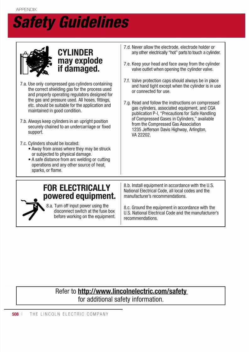
7/18/2019 c110 - Lincoln Electric Consumables 2014
http://slidepdf.com/reader/full/c110-lincoln-electric-consumables-2014 508/511508 ı T H E L I N C O L N E L E C T R I C C O M P A N Y
7.a. Use only compressed gas cylinders containingthe correct shielding gas for the process usedand properly operating regulators designed forthe gas and pressure used. All hoses, fittings,etc. should be suitable for the application andmaintained in good condition.
7.b. Always keep cylinders in an upright positionsecurely chained to an undercarriage or fixedsupport.
7.c. Cylinders should be located:• Away from areas where they may be struck
or subjected to physical damage.• A safe distance from arc welding or cutting
operations and any other source of heat,sparks, or flame.
7.d. Never allow the electrode, electrode holder orany other electrically “hot” parts to touch a cylinder.
7.e. Keep your head and face away from the cylindervalve outlet when opening the cylinder valve.
7.f. Valve protection caps should always be in placeand hand tight except when the cylinder is in useor connected for use.
7.g. Read and follow the instructions on compressedgas cylinders, associated equipment, and CGApublication P-l, “Precautions for Safe Handling
of Compressed Gases in Cylinders,” availablefrom the Compressed Gas Association1235 Jefferson Davis Highway, Arlington, VA 22202.
CYLINDER
may explodeif damaged.
8.a. Turn off input power using thedisconnect switch at the fuse boxbefore working on the equipment.
8.b. Install equipment in accordance with the U.S.National Electrical Code, all local codes and themanufacturer’s recommendations.
8.c. Ground the equipment in accordance with theU.S. National Electrical Code and the manufacturer’srecommendations.
FOR ELECTRICALLYpowered equipment.
Refer to http://www.lincolnelectric.com/safety
for additional safety information.
APPENDIX
Safety Guidelines
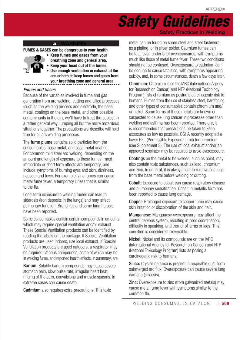
7/18/2019 c110 - Lincoln Electric Consumables 2014
http://slidepdf.com/reader/full/c110-lincoln-electric-consumables-2014 509/511W E L D I N G C O N S U M A B L E S C A TA L O G ı 509
Fumes and Gases
Because of the variables involved in fume and gas
generation from arc welding, cutting and allied processes
(such as the welding process and electrode, the base
metal, coatings on the base metal, and other possible
contaminants in the air), we’ll have to treat the subject ina rather general way, lumping all but the more hazardous
situations together. The precautions we describe will hold
true for all arc welding processes.
The fume plume contains solid particles from the
consumables, base metal, and base metal coating.
For common mild steel arc welding, depending on the
amount and length of exposure to these fumes, most
immediate or short term effects are temporary, and
include symptoms of burning eyes and skin, dizziness,
nausea, and fever. For example, zinc fumes can causemetal fume fever, a temporary illness that is similar
to the flu.
Long-term exposure to welding fumes can lead to
siderosis (iron deposits in the lungs) and may affect
pulmonary function. Bronchitis and some lung fibrosis
have been reported.
Some consumables contain certain compounds in amounts
which may require special ventilation and/or exhaust.
These Special Ventilation products can be identified byreading the labels on the package. If Special Ventilation
products are used indoors, use local exhaust. If Special
Ventilation products are used outdoors, a respirator may
be required. Various compounds, some of which may be
in welding fume, and reported health effects, in summary, are:
Barium: Soluble barium compounds may cause severe
stomach pain, slow pulse rate, irregular heart beat,
ringing of the ears, convulsions and muscle spasms. In
extreme cases can cause death.
Cadmium also requires extra precautions. This toxic
metal can be found on some steel and steel fasteners
as a plating, or in silver solder. Cadmium fumes can
be fatal even under brief overexposures, with symptoms
much like those of metal fume fever. These two conditionsshould not be confused. Overexposure to cadmium can
be enough to cause fatalities, with symptoms appearing
quickly, and, in some circumstances, death a few days later.
Chromium: Chromium is on the IARC (International Agency
for Research on Cancer) and NTP (National Toxicology
Program) lists chromium as posing a carcinogenic risk to
humans. Fumes from the use of stainless steel, hardfacing
and other types of consumables contain chromium and/
or nickel. Some forms of these metals are known or
suspected to cause lung cancer in processes other thanwelding and asthma has been reported. Therefore, it
is recommended that precautions be taken to keep
exposures as low as possible. OSHA recently adopted a
lower PEL (Permissible Exposure Limit) for chromium
(see Supplement 3). The use of local exhaust and/or an
approved respirator may be required to avoid overexposure.
Coatings on the metal to be welded, such as paint, may
also contain toxic substances, such as lead, chromium
and zinc. In general, it is always best to remove coatings
from the base metal before welding or cutting.
Cobalt: Exposure to cobalt can cause respiratory disease
and pulmonary sensitization. Cobalt in metallic form has
been reported to cause lung damage.
Copper: Prolonged exposure to copper fume may cause
skin irritation or discoloration of the skin and hair.
Manganese: Manganese overexposure may affect the
central nervous system, resulting in poor coordination,
difficulty in speaking, and tremor of arms or legs. This
condition is considered irreversible.Nickel: Nickel and its compounds are on the IARC
(International Agency for Research on Cancer) and NTP
(National Toxicology Program) lists as posing a
carcinogenic risk to humans.
Silica: Crystalline silica is present in respirable dust form
submerged arc flux. Overexposure can cause severe lung
damage (silicosis).
Zinc: Overexposure to zinc (from galvanized metals) may
cause metal fume fever with symptoms similar to the
common flu.
FUMES & GASES can be dangerous to your health• Keep fumes and gases from your
breathing zone and general area.• Keep your head out of the fumes.• Use enough ventilation or exhaust at the
arc, or both, to keep fumes and gases fromyour breathing zone and general area.
APPENDIX
Safety Guidelines
WARNING
Safety Practices in Welding

7/18/2019 c110 - Lincoln Electric Consumables 2014
http://slidepdf.com/reader/full/c110-lincoln-electric-consumables-2014 510/511510 ı T H E L I N C O L N E L E C T R I C C O M P A N Y
The gases that result from an arc welding process also
present potential hazard. Most of the shielding gases
(argon, helium, and carbon dioxide) are non-toxic, but, as
they are released, they displace oxygen in your breathingair, causing dizziness, unconsciousness, and death, the
longer your brain is denied the oxygen it needs. Carbon
monoxide can also be developed and may pose a hazard
if excessive levels are present.
The heat and UV radiation can cause irritation to the
eyes and lungs. Some degreasing compounds such as
trichlorethylene and perchlorethylene can decompose
from the heat and ultraviolet radiation of an arc. Because
of the chemical breakdown of vapor-degreasing materials
under ultraviolet radiation, arc welding should not bedone in the vicinity of a vapor-degreasing operation.
Carbon-arc welding, gas tungsten-arc welding and gas
metal arc welding should be especially avoided in such
areas, because they emit more ultraviolet radiation than
other processes. Also, keep in mind that ozone and nitrogen
oxides are formed when UV radiation passes through the
air. These gases cause headaches, chest pains, irritation
of the eyes, and an itchiness in the nose and throat.
There is one easy way to reduce the risk of exposure to
hazardous fumes and gases: keep your head out of thefume plume! As obvious as this sounds, the failure to
follow this advice is a common cause of fume and gas
overexposure because the concentration of fume and
gases is greatest in the plume. Keep fumes and gases
from your breathing zone and general area using natural
ventilation, mechanical ventilation, fixed or moveable
exhaust hoods or local exhaust at the arc. Finally, it may
be necessary to wear an approved respirator if adequate
ventilation cannot be provided.
As a rule of thumb, for many mild steel electrode, if theair is visibly clear and you are comfortable, then the
ventilation is generally adequate for your work. The most
accurate way to determine if the worker exposure does
not exceed the applicable exposure limit for compounds
in the fumes and gases is to have an industrial hygienist
take and analyze a sample of the air you are breathing.
This is particularly important if you are welding with
stainless, hardfacing or Special Ventilation products. All
Lincoln MSDS have a maximum fume guideline number.
If exposure to total fume is kept below that number,
exposure to all fume from the electrode (not coatings orplating on the work) will be below the TLV.
There are also steps that you can take to identify hazardous
substances in your welding environment. First, read the
product label and material safety data sheet for the
electrode posted in the work place or in the electrode
or flux container to see what fumes can be reasonably
expected from use of the product and to determine if
special ventilation is needed. Secondly, know what the
base metal is, and determine if there is any paint, plating,
or coating that could expose you to toxic fumes and/orgases. Remove it from the metal being welded, if possible.
If you start to feel uncomfortable, dizzy or nauseous,
there is a possibility that you are being overexposed to
fumes and gases, or suffering from oxygen deficiency.
Stop welding and get some fresh air immediately. Notify
your supervisor and co-workers so the situation can be
corrected and other workers can avoid the hazard. Be
sure you are following these safe practices, the consumable
labeling and MSDS and improve the ventilation in your
area. Do not continue welding until the situation has beencorrected.
NOTE: The MSDS for all Lincoln consumables is
available on Lincoln’s website: www.lincolnelectric.com
Before we turn to the methods available to control welding
fume exposure, you should understand a few basic terms:
Natural Ventilation is the movement of air through
the workplace caused by natural forces. Outside, this
is usually the wind. Inside, this may be the flow of air
through open windows and doors.
Mechanical Ventilation is the movement of air through
the workplace caused by an electrical device such as a
portable fan or permanently mounted fan in the ceiling
or wall.
Source Extraction (Local Exhaust) is a mechanical
device used to capture welding fume at or near the arc
and filter contaminants out of the air.
APPENDIX
Safety Guidelines

7/18/2019 c110 - Lincoln Electric Consumables 2014
http://slidepdf.com/reader/full/c110-lincoln-electric-consumables-2014 511/511
APPENDIX
Safety GuidelinesSafety Practices in Welding
Ventilation
There are many methods which can be selected
by the user to provide adequate ventilation for the
specific application. The following section providesgeneral information which may be helpful in
evaluating what type of ventilation equipment may
be suitable for your application. When ventilation
equipment is installed, you should confirm worker
exposure is controlled within applicable OSHA PEL
and/or ACGIH TLV. According to OSHA regulations,
when welding and cutting (mild steels), natural
ventilation is usually considered sufficient to meet
requirements, provided that:
1. The room or welding area contains at least10,000 cubic feet (about 22 in x 22 in x 22 in)
f h ld
Your work area has adequate ventilation when there isenough ventilation and/or exhaust to control worker
e pos re to ha ardo s materials in the elding f mes
The ventilation or exhaust needed for your application
depends upon many factors such as:
• Workspace volume
• Workspace configuration
• Number of welders
• Welding process and current
• Consumables used (mild steel, hardfacing, stainless, etc.)
• Allowable levels (TLV, PEL, etc.)
• Material welded (including paint or plating)
• Natural airflow


