
C-RANOpportunities and challenges
Prof. Riku JänttiDepartment of Communications and Networking
8.3.2016
C-RAN
• Introduction• RAN Architecture Options• C-RAN Challenges• Conclusions

Introduction• 5G targets
– support 1,000-fold gains in capacity– connections for 50 or perhaps 500
billion devices– support for wide range of
requirements and characteristics interms of data rates, latency,reliability, energy consumption, anddevice cost.
• The 1,000 –fold capacity gain hasthree factors:
– Spectrum: mostly available above10 GHz
– Spectral efficiency: gains e.g. frommassive and networked MIMO
– Densification: e.g. gains fromultradense indoor deployments
• The key question is how to makethe 1000X capacity gain in a costand energy efficient manner?
Author SpectrumSpectral
Efficiency DensificationTotal Capacity
IncreaseNSN 10X 10X 10X 1000X
Huawei 3X 3.3X 10X 100XNTT Docomo 2.8X 24X 15X 1000X
Zander & Mähönen 3X 5X 66X 1000X
= ∗ ∗
[Zander2013]
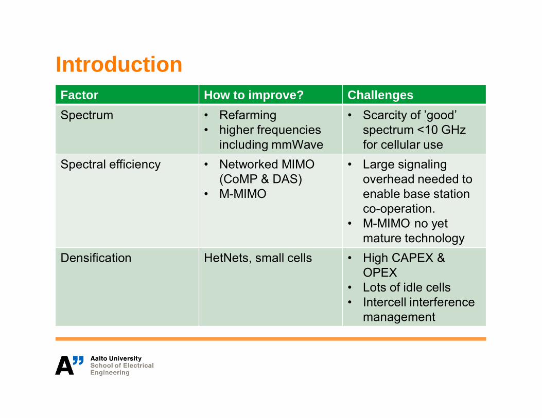
IntroductionFactor How to improve? ChallengesSpectrum • Refarming
• higher frequenciesincluding mmWave
• Scarcity of ’good’spectrum <10 GHzfor cellular use
Spectral efficiency • Networked MIMO(CoMP & DAS)
• M-MIMO
• Large signalingoverhead needed toenable base stationco-operation.
• M-MIMO no yetmature technology
Densification HetNets, small cells • High CAPEX &OPEX
• Lots of idle cells• Intercell interference
management

Cloud-RAN
• Cloud-RAN (C-RAN) is onecandidate technology to solve thechallenges related to densificationand increased base station co-opearation.
• In C-RAN, the Radio AccessNetwork (RAN) functionality ismoved to the cloud computinginfrastructure.
• Remote radio units (RRU) ofdifferent cells are connected to thecloud via a high speed front-haullink, such as a fiber network.
• C-RAN has a central processingsystem in the cloud.
http://m.eet.com/media/1193405/F1mobevolutionx600.jpg
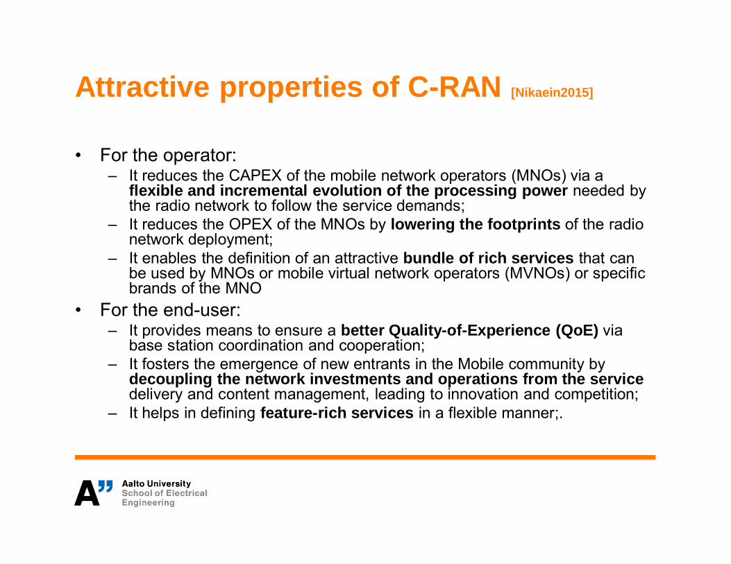
Attractive properties of C-RAN [Nikaein2015]
• For the operator:– It reduces the CAPEX of the mobile network operators (MNOs) via a
flexible and incremental evolution of the processing power needed bythe radio network to follow the service demands;
– It reduces the OPEX of the MNOs by lowering the footprints of the radionetwork deployment;
– It enables the definition of an attractive bundle of rich services that canbe used by MNOs or mobile virtual network operators (MVNOs) or specificbrands of the MNO
• For the end-user:– It provides means to ensure a better Quality-of-Experience (QoE) via
base station coordination and cooperation;– It fosters the emergence of new entrants in the Mobile community by
decoupling the network investments and operations from the servicedelivery and content management, leading to innovation and competition;
– It helps in defining feature-rich services in a flexible manner;.
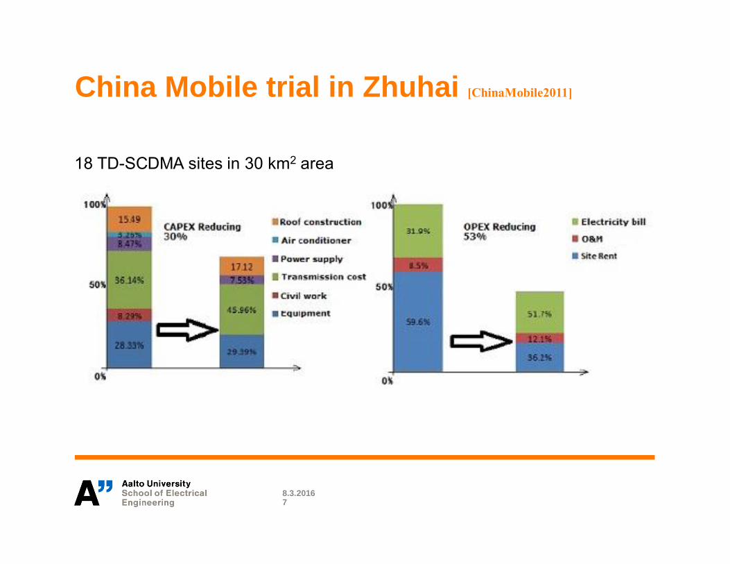
China Mobile trial in Zhuhai [ChinaMobile2011]
8.3.20167
18 TD-SCDMA sites in 30 km2 area

8.3.20168

RAN Architecture Options
8.3.2016
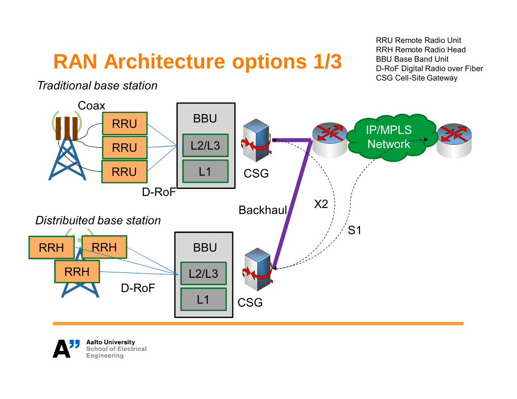
RAN Architecture options 1/3
RRU
RRU
RRU L1
L2/L3
BBU
CSG
IP/MPLSNetwork
D-RoF
Coax
RRH
RRH
RRH
L1
L2/L3
BBU
CSGD-RoF
Traditional base station
BackhaulDistribuited base station
S1
X2
RRU Remote Radio UnitRRH Remote Radio HeadBBU Base Band UnitD-RoF Digital Radio over FiberCSG Cell-Site Gateway
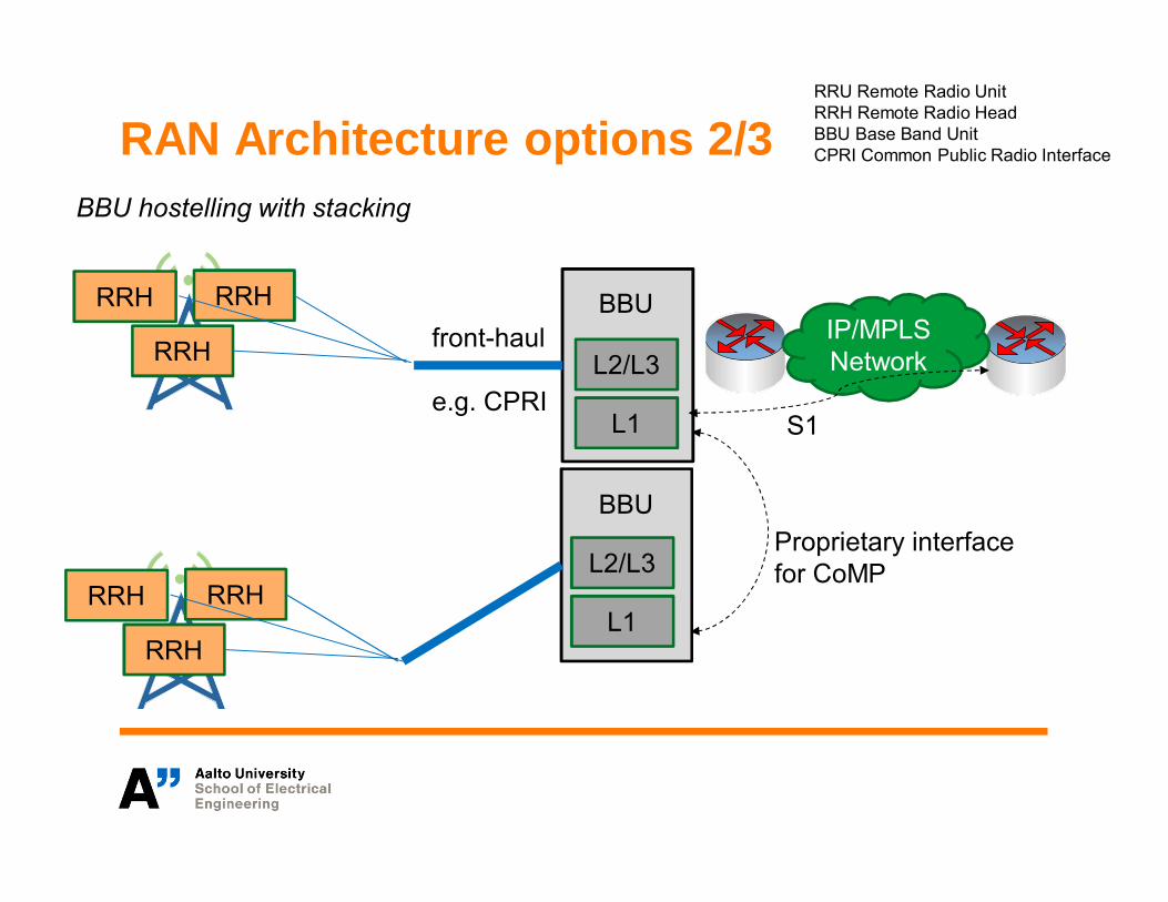
RAN Architecture options 2/3
L1
L2/L3
BBUIP/MPLSNetwork
RRH
RRH
RRHL1
L2/L3
BBU
S1
RRU Remote Radio UnitRRH Remote Radio HeadBBU Base Band UnitCPRI Common Public Radio Interface
front-haul
e.g. CPRI
Proprietary interfacefor CoMP
RRH
RRH
RRH
BBU hostelling with stacking
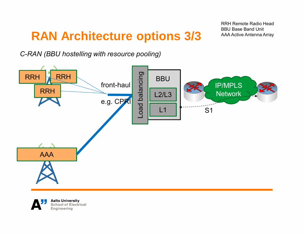
RAN Architecture options 3/3
L1
L2/L3
BBUIP/MPLSNetwork
AAA
S1
RRH Remote Radio HeadBBU Base Band UnitAAA Active Antenna Array
RRH
RRH
RRH
C-RAN (BBU hostelling with resource pooling)
Load
bala
ncin
g
front-haul
e.g. CPRI
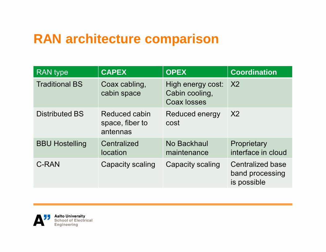
RAN architecture comparison
RAN type CAPEX OPEX CoordinationTraditional BS Coax cabling,
cabin spaceHigh energy cost:Cabin cooling,Coax losses
X2
Distributed BS Reduced cabinspace, fiber toantennas
Reduced energycost
X2
BBU Hostelling Centralizedlocation
No Backhaulmaintenance
Proprietaryinterface in cloud
C-RAN Capacity scaling Capacity scaling Centralized baseband processingis possible

8.3.201614
RA
NE
volu
tion

RAN architecture comparison
• Traditional bases stations utilize ASIC/FPGA for baseband (BB) processing due to strict real-time constraints.
• If BB processing is done in cloud, radio over Fiber isutilized between the central unit and RRH.
• Cloud computing, currently, is a very rapidly developingarea. For the Radio Access Networks to fully benefitfrom advancements in cloud technology and economiesof scale, the amount of features requiring real-timecomputing or special purpose hardware should beminimized.

C-RAN Challenges
8.3.2016

C-RAN Challenges [Nikaein2015, Alyafawi2015]
1. Latency requirements for BBU: LTE HARQ requires a round triptime (RTT) of 8 ms (FDD) that imposes an upper-bound for thesum of BBU processing time and the front-haul transport latency.
2. Real-time requirement for Operating System and virtualizationenvironment: Execution environment of BBU pool must provide(statistical) guarantee for the BBU pool successfully meeting theirreal-time deadlines related to the frame/subframe timing. It shouldalso provide dynamic resource provisioning/sharing and loadbalancing to deal with the cell load variations.
3. Capacity requirement for front-haul: Because a typical BBUpool should support 10 - 1000 base stations, transport of the I/Qsamples from BBU to RRH requires a high front-haul capacity. Tomeet the BBU timing requirements, front-haul must provide anupperbound for the maximum one-way latency (NGMN: 250 λs).Furthermore, clock synchronization across BBUs and RRH overthe front-haul also imposes a very low jitter.
C-RAN Opportunities
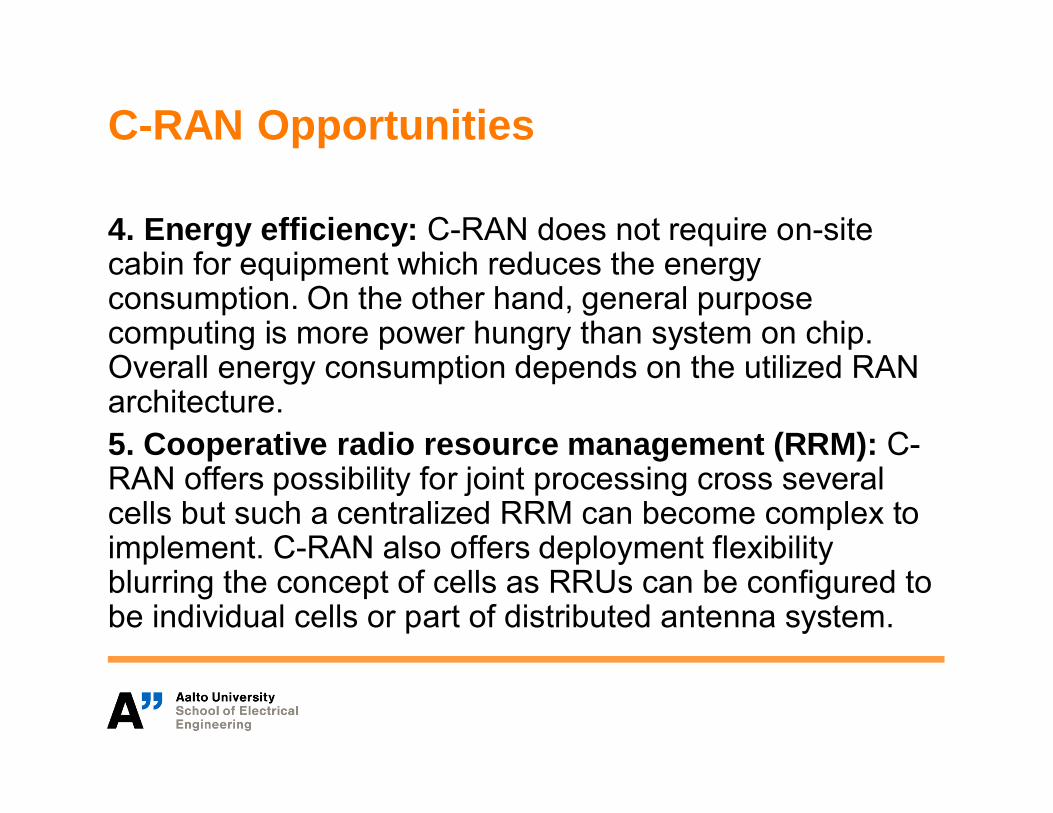
4. Energy efficiency: C-RAN does not require on-sitecabin for equipment which reduces the energyconsumption. On the other hand, general purposecomputing is more power hungry than system on chip.Overall energy consumption depends on the utilized RANarchitecture.5. Cooperative radio resource management (RRM): C-RAN offers possibility for joint processing cross severalcells but such a centralized RRM can become complex toimplement. C-RAN also offers deployment flexibilityblurring the concept of cells as RRUs can be configured tobe individual cells or part of distributed antenna system.
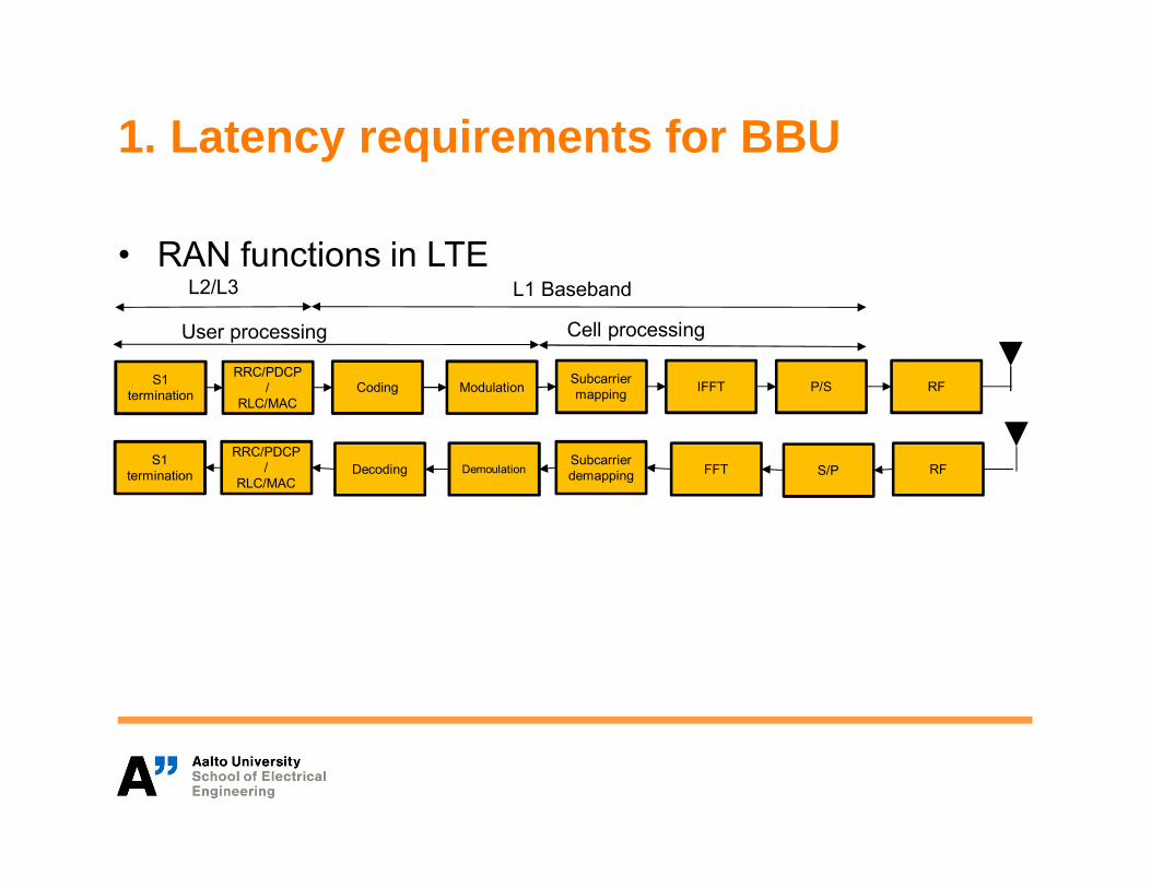
1. Latency requirements for BBU
• RAN functions in LTE
S1termination
RRC/PDCP/
RLC/MACCoding Modulation Subcarrier
mapping IFFT P/S RF
S1termination
RRC/PDCP/
RLC/MACDecoding Demoulation
Subcarrierdemapping FFT S/P RF
L2/L3 L1 Baseband
User processing Cell processing

1. Latency requirements for BBU
• HARQ timing
8.3.201620
… N N+1 N+2 N+3 N+4 N+5 N+6 N+7 ….eNB
… N N+1 N+2 N+3 N+4 N+5 N+6 N+7 ….UE
Offset
ACK/NACK
UE Processing
eNB processingPropagagtion+Acquisition+Transport RX Processing TX Processing
Propagagtion+Transport
Aquisation RX Processing TX Processing

1. Latency requirements for BBU
• To meet the timing requirements, the BBU processingmust finish before the deadlines imposed by the HybridAutomatic Repear Request (HARQ) protocol.
• 1 ms Tx processing time and 2 ms Rx processing time
8.3.201621
∋ (HARQRx Tx Propagation Acquisation Transport Offset
HARQ
Propagation Acquisation Transport
Offset
32
8 ,1
0 in downlink
TT T T T T T ms
T msT T T msT ms
∗ ′ , ∗ ∗ ∗ ′
<
∗ ∗ ′
<

2. Real-time requirement for OperatingSystem and virtualization environment• A typical general purpose operating system (GPOS)
such a Linux is not designed to support real-timeapplications with hard deadline.
• In Linux, one can use SCHED_DEADLINE scheduler tosupport real-time operation. Each application needs tospecify triple (runtime [ns], deadline [ns], period [ns]).
• Typically, software defined radio assumes strict real-timeto maintain frame and subframe (and symbol) timing.
• In C-RAN, the software needs to run in virtualizedenvironment where hardware is either fully or partiallyvirtualized.
8.3.201622
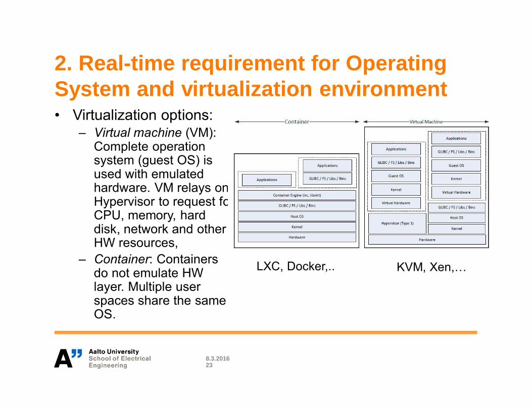
2. Real-time requirement for OperatingSystem and virtualization environment• Virtualization options:
– Virtual machine (VM):Complete operationsystem (guest OS) isused with emulatedhardware. VM relays onHypervisor to request forCPU, memory, harddisk, network and otherHW resources,
– Container: Containersdo not emulate HWlayer. Multiple userspaces share the sameOS.
8.3.201623
KVM, Xen,…LXC, Docker,..
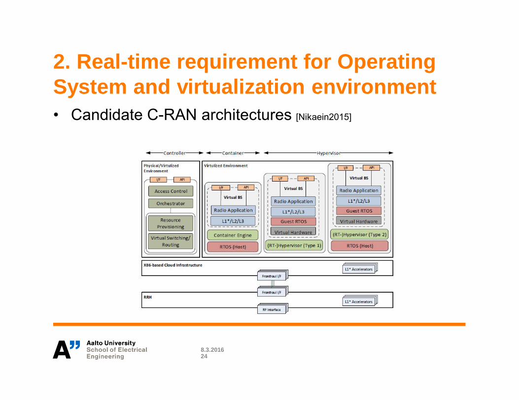
2. Real-time requirement for OperatingSystem and virtualization environment• Candidate C-RAN architectures [Nikaein2015]
8.3.201624
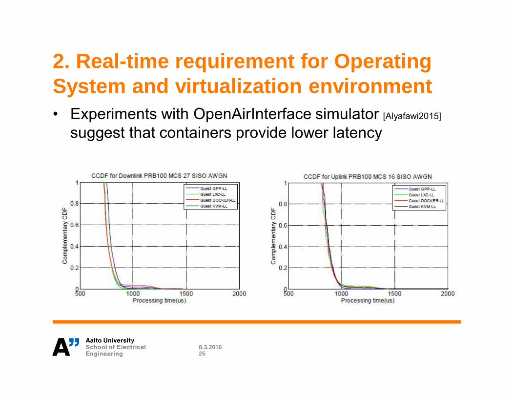
2. Real-time requirement for OperatingSystem and virtualization environment• Experiments with OpenAirInterface simulator [Alyafawi2015]
suggest that containers provide lower latency
8.3.201625

Relaxing the real-time requirement: Soft-real time C-RAN [Kerttula2014]
• The strict real-time requirement of the C-RAN can berelaxed with the cost of reduced performance.
• Non-real-time operation system (NRTOS) such as Linuxwith default scheduler, is not able to guaranteed thatbase band processing meets the deadline.
• Missing base band packet can be interpreted as a lostsubframe and compesated by retransmission in HARQ.
8.3.201626
BB BB BBOS OS
DeadlineScheduler
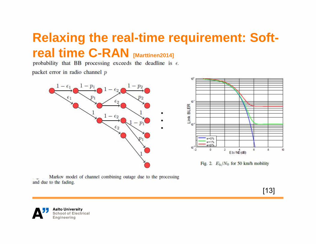
Relaxing the real-time requirement: Soft-real time C-RAN [Marttinen2014]
[13]

Relaxing the real-time requirement: Soft-real time C-RAN [Kerttula2014, Beyene2014]
• Soft-real timeaarchitecture allowsflexible mapping ofRRUs to BB Processes.
• Communication betweenC-RAN and RRU isdone over givabitEthernet (Digital IQ)
Relaxing the real-time requirement: Soft-real time C-RAN [Kerttula2014]
• Running real-time baseband processing on a non-real-time GPP computer - or even a virtual machine -requires new architectural solutions.
• Main challenges for implementation– clock skew,– unreliable link between the BBU and RRH– latency between the BBU and RRH– random delays in BB processing

Relaxing the real-time requirement: Soft-real time C-RAN [Kerttula2014]
• Clock inaccuracy– Over the air synchronization– Continuous correlation with
synchronization signal.– If correlation is earlier or later than
expected (clock drift) add or remove onesample
• Lost data from RRH to BB unit direction– Tracks the sample number from front haul
link metadata– If samples are lost, zeros are inserted– Higher layers see a continuous sample
stream on which they operate– Always the correct number of samples
(per packet)• Late data from higher layers (due to the
non RT nature)– Estimate the latest moment when the
packet has to be sent to RRH– If the packet is not ready by due time
send padding instead
8.3.201630
Subframe type dependentpadding when delay overflow
Down-stream
TAU
Networkinterface
Fronthaulnetwork
RRU
Soft real time
Block time
Sample time
Sample time
Stochasticnetwork time
BBU
Buffer
Communicationprocess
BUF
Networkinterface
Up-stream
L-CLK1
S-CLK
Relaxing the real-time requirement: Soft-realtime C-RAN [Kerttula2014]
• Buffer layer– Hides late subframes by sending dummies to maintain frame
alignment– Interfaces real-time clock of radio interface and packet
processing in PC• Higher layer processing will operate on packets without
explicit sample time knowledge.• Simplifies implementation of base band processing• Timing uncertainty can be incorporated into channel
model– Late subframes appear as ”fading”– Missing sub-frames are compensated by HARQ
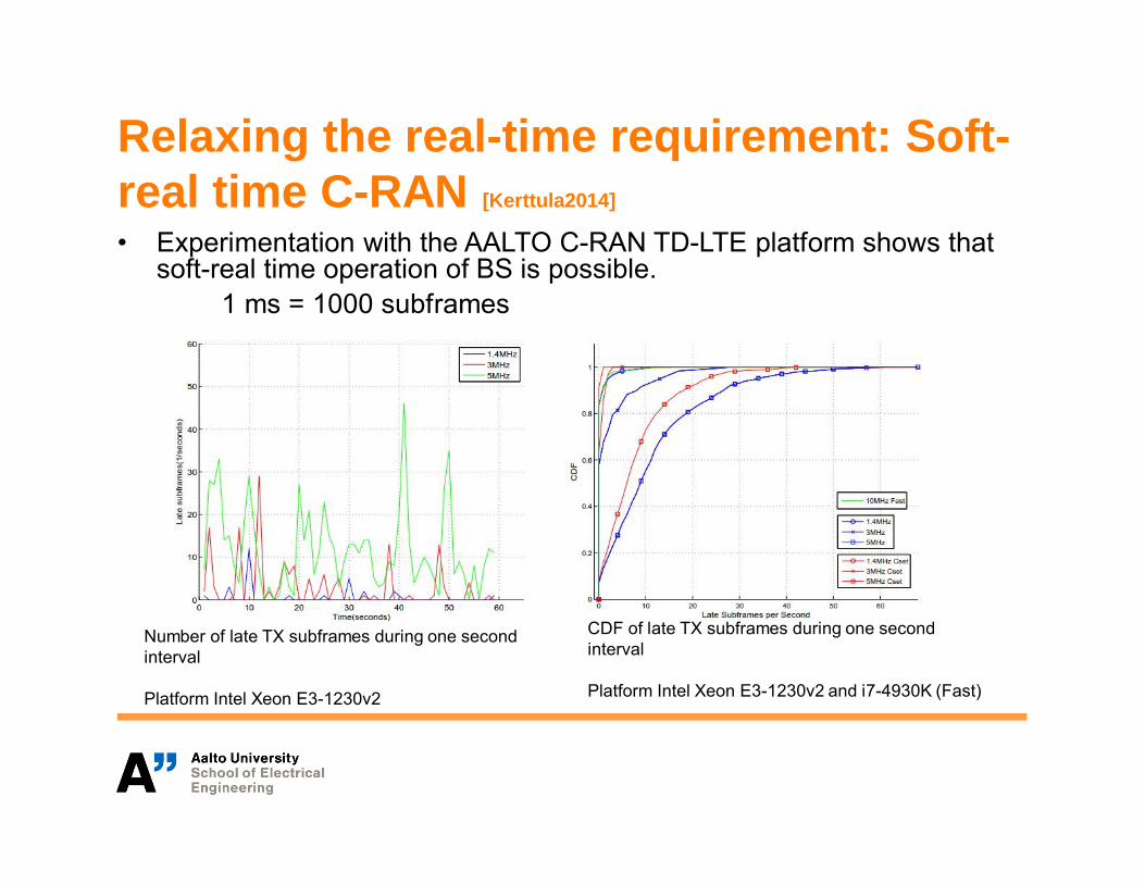
Relaxing the real-time requirement: Soft-real time C-RAN [Kerttula2014]
• Experimentation with the AALTO C-RAN TD-LTE platform shows thatsoft-real time operation of BS is possible.
1 ms = 1000 subframes
Number of late TX subframes during one secondinterval
Platform Intel Xeon E3-1230v2
CDF of late TX subframes during one secondinterval
Platform Intel Xeon E3-1230v2 and i7-4930K (Fast)

Relaxing the real-time requirement: Soft-real time C-RAN• Soft-real time operation of C-RAN would allow the use of
general purpose cloud platforms for providing RAN as aservice (RANaaS).
8.3.201633
3. front-haul capacity requirement[Nikaein2015, Alyafawi2015]
• Current interfaces between BBU and RRH are providedin a "semi proprietary" nature, although based onindustry standards like Common Public Radio Interface(CPRI) or Open Base Station Architecture (OBSAI)
• ETSI standard for Open Radio Interface (ORI) has beenrecently introduced.– Support for point-to-point, multiple point-to-point, tree and ring
topologies– Maximum front-haul latency 250 λs– front-haul link distance limited to between 15 km to 40 km
(speed of light in a fiber is approx. 200 m/λs)
8.3.201634
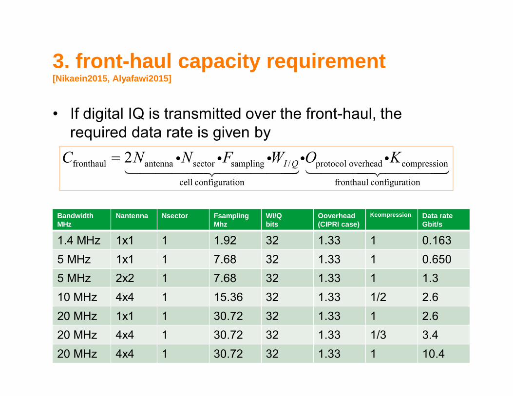
3. front-haul capacity requirement[Nikaein2015, Alyafawi2015]
• If digital IQ is transmitted over the front-haul, therequired data rate is given by
8.3.201635
fronthaul antenna sector sampling / protocol overhead compression
cell configuration fronthaul configuration
2 I QC N N F W O K< φ φ φ φ φ0333331333332 03333133332
BandwidthMHz
Nantenna Nsector FsamplingMhz
WI/Qbits
Ooverhead(CIPRI case)
Kcompression Data rateGbit/s
1.4 MHz 1x1 1 1.92 32 1.33 1 0.1635 MHz 1x1 1 7.68 32 1.33 1 0.6505 MHz 2x2 1 7.68 32 1.33 1 1.310 MHz 4x4 1 15.36 32 1.33 1/2 2.620 MHz 1x1 1 30.72 32 1.33 1 2.620 MHz 4x4 1 30.72 32 1.33 1/3 3.420 MHz 4x4 1 30.72 32 1.33 1 10.4

Reducing the front-haul capacityrequirement by function splitting.• Transmission of the digital IQ requires very high front-haul
capacity.• To cope with this problem a number of baseband
compression algorithms have been proposed.• ETSI ORI limits maximum one way IQ compression / decompression
delay < 100 λs (preferably 20 λs for LTE)High compression delay => less propagation time => shorter front-haul links– Time domain compression algorithms are simple and fast but
provide limited compression rates (1/2 or 1/3).[Samardzija2012]– Frequency domain compression algorithms can achieve much
higher compression rates but are computationally more heavy.– Very high compression can be obtained (1/30) by relocating
modulation, precoding and FFT/IFFT to RRH. [Lorca2013]
8.3.201636
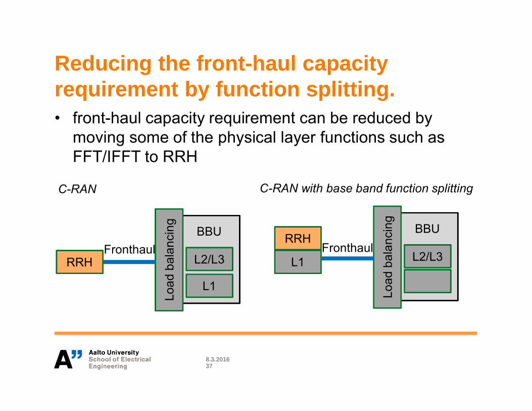
Reducing the front-haul capacityrequirement by function splitting.• front-haul capacity requirement can be reduced by
moving some of the physical layer functions such asFFT/IFFT to RRH
8.3.201637
L2/L3
BBU
Load
bala
ncin
g
RRH
L1
L1
L2/L3
BBU
Load
bala
ncin
g
RRHFronthaul
C-RAN C-RAN with base band function splitting
Fronthaul
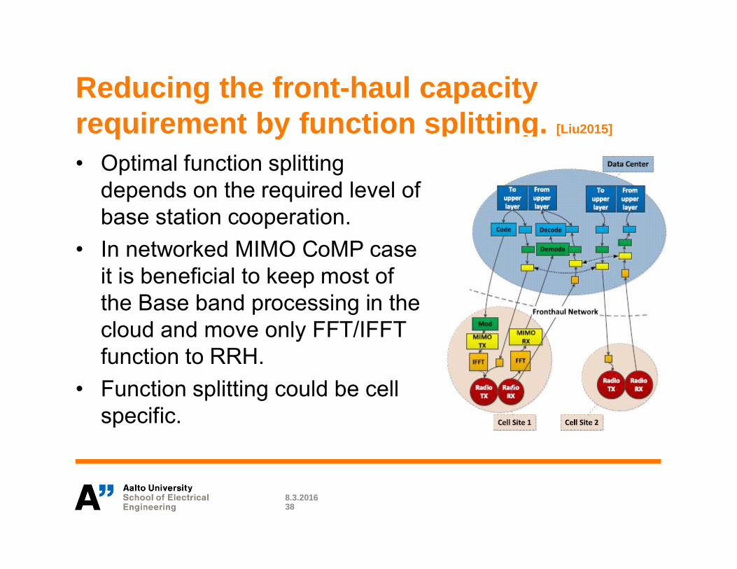
Reducing the front-haul capacityrequirement by function splitting. [Liu2015]
• Optimal function splittingdepends on the required level ofbase station cooperation.
• In networked MIMO CoMP caseit is beneficial to keep most ofthe Base band processing in thecloud and move only FFT/IFFTfunction to RRH.
• Function splitting could be cellspecific.
8.3.201638
4. Energy Efficiency
• C-RAN energy consumption using OpenAirInterface[Nikaein2015]
– General Purpose Processor base band processing: 70 W percarrier
– Accelerated - Certain functions such as FFT/IFFT offloaded todedicated hardware: 13-18 W per carrier
– System on Chip - All L1 processing in base station: approx. 8 Wper carrier
• Additional energy saving is obtained– due to reduced equipment at cell site: No need for cabin, air-
conditioning, less computation power at RRH– scaling of computation units based on load
8.3.201639

C-RAN Energy optimization [Marttinen2014]
• In GPP energy can be saved through dynamic voltage scalingDVS) which will impact the speed of the processor
• In case of NRTOS, OS housekeeping tasks and task canoccasionally delay base band processing
• A base station (BS) is a real-time system where each packethas to be prepared for the transmission at certain time moment.
• If baseband processing of the packet is late, the system missestransmission opportunity and for the receiver the packet seemsto be lost.
• Fortunately, communication systems have automatic repeatrequest (ARQ) mechanism to cope with the lost packets.
• Hence we can trade off performance for reduced compuptingpower.
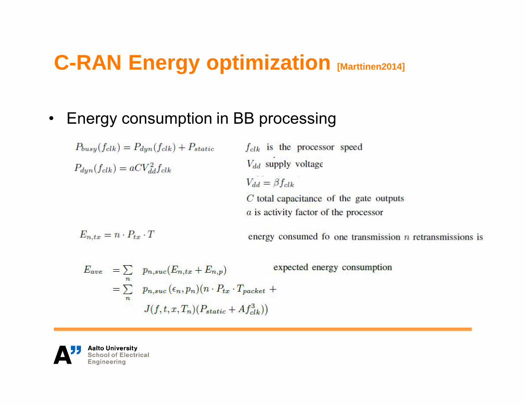
C-RAN Energy optimization [Marttinen2014]
• Energy consumption in BB processing
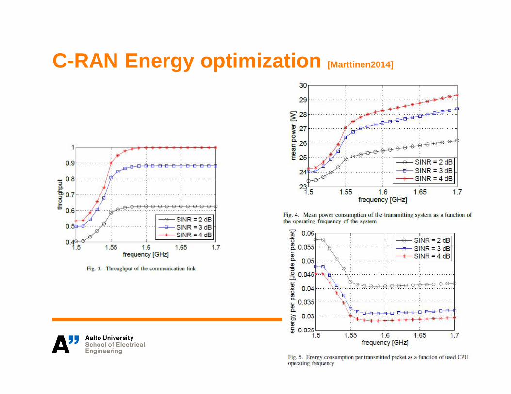
C-RAN Energy optimization [Marttinen2014]
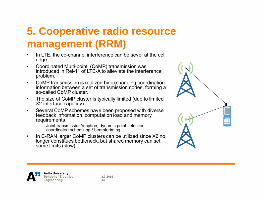
5. Cooperative radio resourcemanagement (RRM)• In LTE, the co-channel interference can be sever at the cell
edge.• Coordinated Multi-point (CoMP) transmission was
introduced in Rel-11 of LTE-A to alleviate the interferenceproblem.
• CoMP transmission is realized by exchanging coordinationinformation between a set of transmission nodes, forming aso-called CoMP cluster.
• The size of CoMP cluster is typically limited (due to limitedX2 interface capacity)
• Several CoMP schemes have been proposed with diversefeedback infromation, computation load and memoryrequirements
– Joint transmission/recption, dynamic point selection,coordinated scheduling / beamforiming
• In C-RAN larger CoMP clusters can be utilized since X2 nolonger constitues bottleneck, but shared memory can setsome limits (slow)
8.3.201643

5. Cooperative radio resourcemanagement (RRM) [I2014]
• Field trial results suggest that 40% to 100% CoMP gains canbe achieved.
• Comp cluster = Ring 1, Interference over thermal 13 ~ 16 dB
8.3.201644
5. Cooperative radio resourcemanagement (RRM)• C-RAN offers flexibility:
– C-RAN can change between DAS, antenna selection, and smallcell configurations in the deployment area in a flexible mannerdepending on the type and volume of the traffic.
– For instance during low load situations, the system could beorganized to provide coverage in the most energy efficientmanner and then as the load increases small cells can beformed in traffic hotspots.
– For ultra-reliable communications, the system could beconfigured to maximize the connectivity probability and diversitygains.
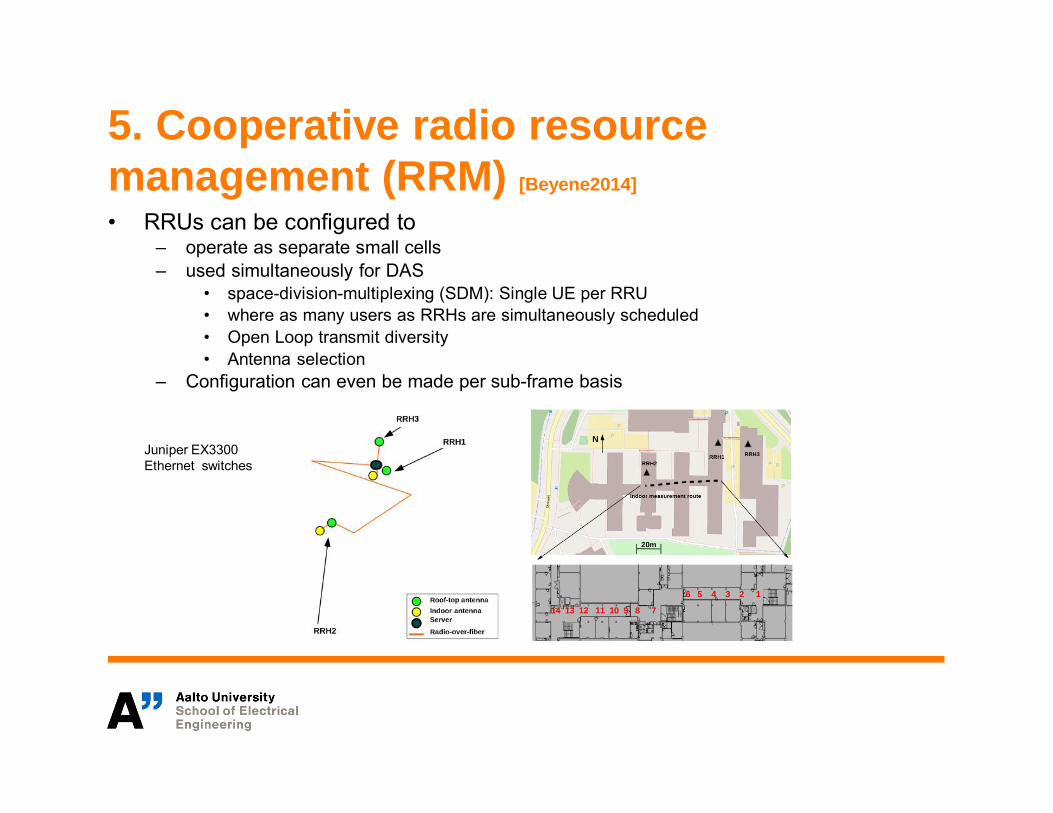
5. Cooperative radio resourcemanagement (RRM) [Beyene2014]
• RRUs can be configured to– operate as separate small cells– used simultaneously for DAS
• space-division-multiplexing (SDM): Single UE per RRU• where as many users as RRHs are simultaneously scheduled• Open Loop transmit diversity• Antenna selection
– Configuration can even be made per sub-frame basis
Juniper EX3300Ethernet switches

5. Cooperative radio resourcemanagement (RRM) [Beyene2014]
• Bit error rate
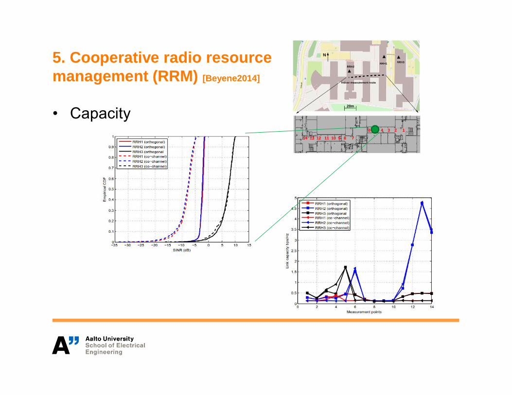
5. Cooperative radio resourcemanagement (RRM) [Beyene2014]
• Capacity

5. Cooperative radio resourcemanagement (RRM)• While C-RAN offers the possibility for centralized radio
resource management, centralized processing my notbe efficient.– From computation point of view it is beneficial to parallelize the
computations as much as possible.– Sharing information between base band ’pipes’ may require the
use of shared memory.– Accessing shared memeory is slow which may consitute
problem in the real-time computation.
8.3.201649
Towards 5G
8.3.2016
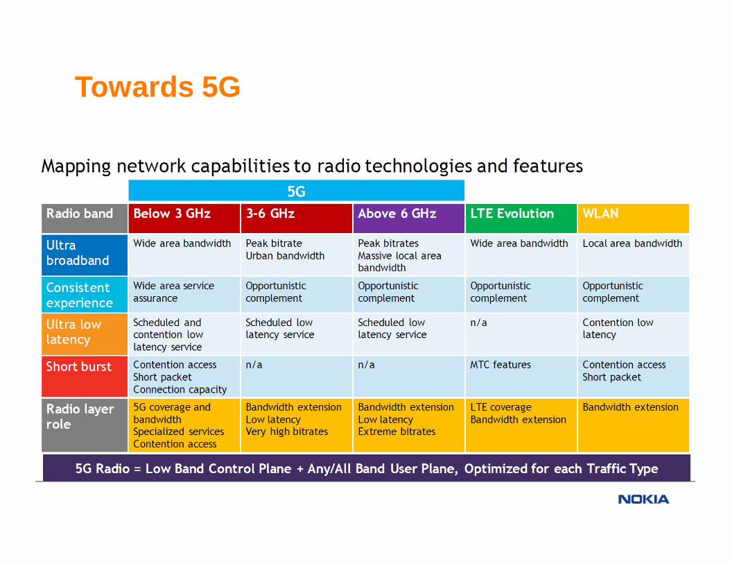
Towards 5G
8.3.201651
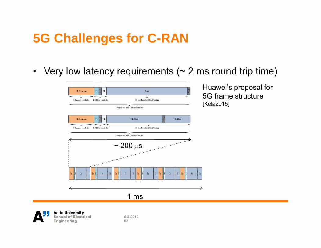
5G Challenges for C-RAN
• Very low latency requirements (~ 2 ms round trip time)
8.3.201652
Huawei’s proposal for5G frame structure[Kela2015]
~ 200 λs
1 ms
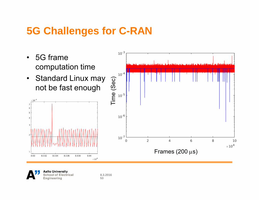
5G Challenges for C-RAN
• 5G framecomputation time
• Standard Linux maynot be fast enough
8.3.201653
Frames (200 λs)
Tim
e(S
ec)

5G Challenges for C-RAN
• Carrier aggregation, & mmWave– Very large bandwidths
• Massive MIMO (M-MIMO)– Massive IQ load
• Ultra dense networks (UDN)– Very large number of sites– Wireless back/mid-hauls
8.3.201654
https://www.ceragon.com/images/Reasource_Center/Solution_Briefs/Ceragon_Solution_Brief_Wireless_Backhaul_Solutions_for_Small_Cells.pdf
[Vieira2014]
http://radio.aalto.fi/en/research/projects/lens_antenna_with_feed_array_for_beam_steering/
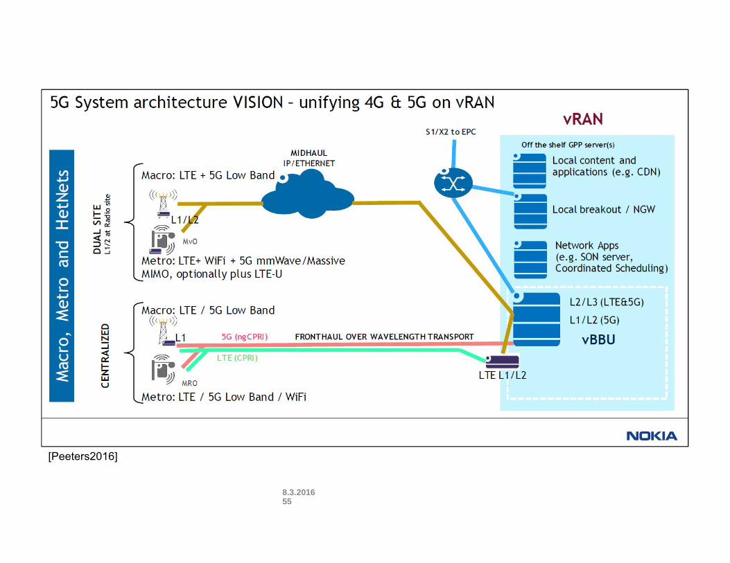
[Peeters2016]
8.3.201655
[Peeters2016]

Conclusions
8.3.2016
Conclusions
• C-RAN is attractive to operators due to reduced OPEX and CAPEX.It also offers better coordination between base stations.
• The choice of architecture has impact on implementationcomplexity, front-haul capacity need, and energy consumption.
• How to divide the functions between GPP, accelerators and RRUdepend on the utilized coordination (CoMP) strategy.
• C-RAN offers deployment flexibility. The concept of cell and basestation becomes blurred as there is only remote radio units that canbe controlled centrally.
• Typically fronthoul is the bottleneck.• 5G will impose great challenges for C-RAN due to increased front-
haul capacity needs and reduced latency requirements.
8.3.201657

Conclusions
• Performance could be traded off for implementation simplicity,energy efficiency, and scalability. The performance loss issmall in nomadic environments.
• GPP/NRTOS Cloud-RAN solutions can help to drive the costof operating the cellular infrastructure down and allow thesystem to adapt to the heterogeneous needs of theapplications.
• Combined with other advancements such as self-organizationand spectrum sharing, C-RAN can potentially open up newmarket for cellular infrastructure as a service for small localoperators (rural broadband), building and facility owners,factories and utility companies etc.

References[ChinaMobile2011] C-RAN The Road Towards Green RAN, White paper, China Mobile, October 2011[Samardzija2012] D. Samardzija, J. Pastalan, M. MacDonald, S. Walker, and R. Valenzuela, ”Compressed transport of baseband signals inradio access networks,” IEEE Transactions on Wireless Communications, vol. 11, no. 9, pp. 3216 – 3225, September 2012.[Ericsson2013] Ericsson, 5G Radio Access – Research and Vision, white paper, 2013. [Online] Available:http://www.ericsson.com/res/docs/whitepapers/wp-5g.pdf[Zander2013] J. Zander and P. Mähönen, “Riding the Data Tsunami in the Cloud: Myths and Challenges in Future Wireless Access,” IEEECommunications Magazine, March 2013.[Nikaein2015] N. Nikaein, Latency, Cooperation, and Cloud in Radio Access Network, HDR Thesis, SophiaTech, France, February 2015.[Alyafawi2015] I. Alyafawi, E. Schiller, T. Braun, D. Dimitrova, A. Gomes, and N. Nikaein. Critical issues of centralized and cloudified lte fddradio access networks. In ICC, 2015.[Lorca2013] J. Lorca and L. Cucala, ”Losless compression techniique for the front-haul of LTE/LTE-advanced cloud-.RAN architectures,” Inproc. IEEE WoWMoM, June 2013.[Liu2015] J. Liu, S. Zhou, J. Gong, Z. Niu and S. Xu, ”Graph-based Framework for Flexible Baseband Function Splitting and Placement in C-RAN, ICC2015.[I2014] C.-C. I, J. Huang, R. Duan, C. Cui. J. Jiang, and L. Li, ”Recent Profress on C-RAN Centralization and Cloudification,” IEEE Access, September2014.[Vieira2014] J. Vieira, S. Malkowsky, K. Nieman et.al. ,”Flexible 100-antenna testbned for Massive MIMO,” In Prof. IEEE Globecom 2014, Austin,Texas[Kerttula2014] J. Kerttula, N. Malm, K. Ruttik, R. Jäntti, and O. Tirkkonen, ”Implementing TD-LTE as software defined radio in general purposeprocessor,” In Proc. ACM Annual Conference of the Special Interest Group on Data Communication SIGCOMM 2014, Chigago, USA, August 17-22,2014[Marttinen2014] A. Marttinen, R. Jäntti, and K. Ruttik, ”Saving energy in base station with non real time operation system in Cloud-RAN,” In Proc.Globecom 2014, Austin Tx, USA, December 8-12, 2014.[Beyene2014] Beyene, Y.D.; Jantti, R.; Ruttik, K., "Cloud-RAN Architecture for Indoor DAS," Access, IEEE , vol.2, no., pp.1205,1212, 2014[Kela2015] Kela, Petteri; Costa, Mario; Salmi, Jussi; Leppanen, Kari; Turkka, Jussi; Hiltunen, Tuomas; Hronec, Michal, "A Novel Radio Frame Structurefor 5G Dense Outdoor Radio Access Networks," Vehicular Technology Conference (VTC Spring), 2015 IEEE 81st , vol., no., pp.1,6, 11-14 May 2015[Peeters2016] M. Peeters, 5G: History Repeating Itself?, talk at Aalto University 28.1.2016


