
1
®
DESCRIPTION
The Fireye® BurnerLogix™ Z System expands on the standard BurnerLogix Y System (see bulletinBL-1001) by combining boiler control functions with the same burner management control found inthe Y system. The result is a single compact package that can directly control the boiler's output fir-ing rate based on either input pressure or temperature or both. The BurnerLogix Z System isdesigned to provide the proper burner sequencing, ignition and flame monitoring protection on auto-matically ignited oil, gas, and combination fuel burners. Through the display, the operator programsthe desired setpoint, cut in, cut out and modulating range and with PID control, the BurnerLogix ZSystem controls the burner/boiler from start up through shutdown, precisely maintaining the desiredsetpoint. The BurnerLogix Z System continuously monitors interlocks and limits found in the L1-3and 3-P circuits as it programs the burner/blower motor, ignition and fuel valves to provide forproper and safe burner operation. VFD and LCD displays are available that may be either plugged inor mounted remotely to give full language descriptors of current status and diagnostic lockout infor-mation as well as provide a user friendly menu system to make setting the boiler parameters easy andunderstandable. Through SMART LED'S, located on the front cover or through the display interface,the control provides current operating status and lockout information in the event of a safety shut-down. Following are some of the major control and monitor capabilities provided by the Burner-Logix Z System:• Operating Control Function for automatic sequencing of the boiler system to start and stop the
boiler to meet system demand.• Full Modulation Control of fuel and combustion air through the firing rate motor to meet sys-
tem demand.• Solid State Sensors to monitor steam pressure, water temperature, stack temperature, boiler
water temperature, or outdoor air temperature.• High Pressure and Temperature Alarm Limits based on inputs from solid state sensors.
Exceeded limits will open interlock circuit to the flame safeguard control for shutdown of theburner and boiler.
• Cold Start Thermal Shock Protection to slowly increase the burner firing rate on a cold startto limit mechanical stress due to thermal differences.
• Multiple Lead/Lag operation of two or more boilers.• User-friendly keypad display system in either VFD or LCD format featuring the all-info dis-
play mode, program and review of system setpoints and operating parameters.• Remote Communication Capability allows reading and writing of all setpoint information.• Password Protected Parameters (two levels of security) to restrict unauthorized entry and
modification of system setpoints and operating parameters.
ZB110/ZB230 FIREYE®
BurnerLogiX™
MICROPROCESSOR-BASED
BURNER MANAGEMENT CONTROL
WITH INTEGRATED BOILERCONTROL OPERATION
BLZ-1001
APPROVED
December 17, 2008

2
®
• Marginal High Pressure and Temperature Alarm Limits based on input from solid state sen-sors to indicate system approaching high alarm limits.
• Programmable Maximum High Fire Position of modulating firing rate damper motor.• Assured low fire cut off prevents unnecessary stress caused by burner shut down at high fire.• Auto / Manual firing rate control with bumpless transferA complete BurnerLogix Z System includes the ZB110 (ZB230) chassis equipped with the type offlame amplifier required for the application, appropriate flame detector, plug-in programmer module,appropriate temperature/pressure transducer, wiring base and alpha-numeric display. InterchangeableYP1XX type programmer modules allow for complete versatility in selection of function, timing andflame failure response times. Refer to BurnerLogix PROGRAMMER SELECTION later in this doc-ument for the various combinations of programmer and display modules.
The ZB110 (ZB230) is a chassis/flame amplifier module complete with mounting screws and blankdisplay module. The display module (BLV512 or BLL510), if required, must be ordered separately.Functions such as pre-purge time, recycling or non-recycling interlocks, high fire proving interlock,and trial for ignition timing of the pilot and main flame are determined by the programmer module.The BurnerLogix Z System can be used with ultra-violet, autocheck infrared, flame rod, self-checkultraviolet flame scanners or direct coupled by choosing the proper chassis/flame amplifier module.Wiring bases for the BurnerLogix Z control are available pre-wired with 4 foot lead wires colorcoded and marked for easy installation or with an integral terminal block capable of a accepting up to2 X 14 AWG wires. The wiring base terminal block is available with knockouts for conduit or openended for cabinet mounting. The pigtail wiring base is 4" X 5" and the terminal block wiring base is4" X 7".Additional functions of the BurnerLogix Z System include:• A non-volatile memory which allows the control to remember its history and present position
even when power is interrupted.• A consistent flame signal read-out via display module or 4-20 mA output.• Read-out of main fuel operational hours and complete cycles via display module.• Modbus communications via RS485 multi-drop link.• Proof of fuel valve closure during off cycle.• Burn-in time of program parameters occurs after 8 hours of main valve on time.• A run/check switch which allows the operator to stop the program sequence in any of four
different positions (Purge, PTFI, MTFI or Auto).• Remote Display mounting with NEMA 4 protection.• Remote Reset• Programmable communication baud rate allows for DCS compatibility.• Keypad selectable language readout.• Revert to pilot can increase burner turn down.• Additional terminals provided for applications requiring additional inputs and outputs.
CAUTION: While programmers are mechanically interchangeable in that they mate with acommon chassis/amplifier module, you should select the correct model for your application.Inappropriate application of a control could result in an unsafe condition hazardous to lifeand property. Selection of a control for a particular application should be made by a compe-tent professional, such as a boiler/burner service technician licensed by a state or other gov-ernment agency.
WARNING: Electro-mechanical high steam pressure or high water temperature limits mustremain in the running interlock circuit of the flame safeguard control.
3
®
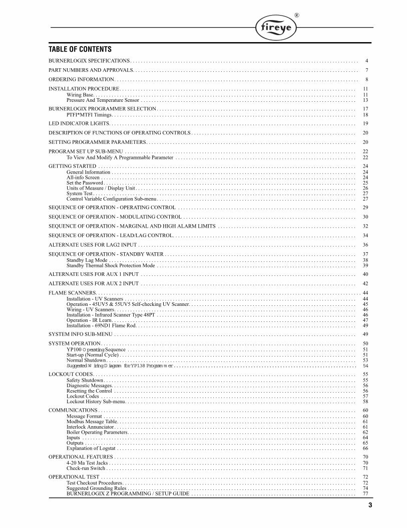
TABLE OF CONTENTS
BURNERLOGIX SPECIFICATIONS. . . . . . . . . . . . . . . . . . . . . . . . . . . . . . . . . . . . . . . . . . . . . . . . . . . . . . . . . . . . . . . . . . . . . . . . . . . . . . . . . . . . . . 4
PART NUMBERS AND APPROVALS. . . . . . . . . . . . . . . . . . . . . . . . . . . . . . . . . . . . . . . . . . . . . . . . . . . . . . . . . . . . . . . . . . . . . . . . . . . . . . . . . . . . . 7
ORDERING INFORMATION. . . . . . . . . . . . . . . . . . . . . . . . . . . . . . . . . . . . . . . . . . . . . . . . . . . . . . . . . . . . . . . . . . . . . . . . . . . . . . . . . . . . . . . . . . . . 8
INSTALLATION PROCEDURE. . . . . . . . . . . . . . . . . . . . . . . . . . . . . . . . . . . . . . . . . . . . . . . . . . . . . . . . . . . . . . . . . . . . . . . . . . . . . . . . . . . . . . . . . 11Wiring Base. . . . . . . . . . . . . . . . . . . . . . . . . . . . . . . . . . . . . . . . . . . . . . . . . . . . . . . . . . . . . . . . . . . . . . . . . . . . . . . . . . . . . . . . . . . . . . . . . . . 11Pressure And Temperature Sensor . . . . . . . . . . . . . . . . . . . . . . . . . . . . . . . . . . . . . . . . . . . . . . . . . . . . . . . . . . . . . . . . . . . . . . . . . . . . . . . . . 13
BURNERLOGIX PROGRAMMER SELECTION . . . . . . . . . . . . . . . . . . . . . . . . . . . . . . . . . . . . . . . . . . . . . . . . . . . . . . . . . . . . . . . . . . . . . . . . . . . 17PTFI*MTFI Timings. . . . . . . . . . . . . . . . . . . . . . . . . . . . . . . . . . . . . . . . . . . . . . . . . . . . . . . . . . . . . . . . . . . . . . . . . . . . . . . . . . . . . . . . . . . . 18
LED INDICATOR LIGHTS. . . . . . . . . . . . . . . . . . . . . . . . . . . . . . . . . . . . . . . . . . . . . . . . . . . . . . . . . . . . . . . . . . . . . . . . . . . . . . . . . . . . . . . . . . . . . 19
DESCRIPTION OF FUNCTIONS OF OPERATING CONTROLS . . . . . . . . . . . . . . . . . . . . . . . . . . . . . . . . . . . . . . . . . . . . . . . . . . . . . . . . . . . . . . 20
SETTING PROGRAMMER PARAMETERS. . . . . . . . . . . . . . . . . . . . . . . . . . . . . . . . . . . . . . . . . . . . . . . . . . . . . . . . . . . . . . . . . . . . . . . . . . . . . . . 20
PROGRAM SET UP SUB-MENU . . . . . . . . . . . . . . . . . . . . . . . . . . . . . . . . . . . . . . . . . . . . . . . . . . . . . . . . . . . . . . . . . . . . . . . . . . . . . . . . . . . . . . . 22To View And Modify A Programmable Parameter . . . . . . . . . . . . . . . . . . . . . . . . . . . . . . . . . . . . . . . . . . . . . . . . . . . . . . . . . . . . . . . . . . . . 22
GETTING STARTED . . . . . . . . . . . . . . . . . . . . . . . . . . . . . . . . . . . . . . . . . . . . . . . . . . . . . . . . . . . . . . . . . . . . . . . . . . . . . . . . . . . . . . . . . . . . . . . . . 24General Information . . . . . . . . . . . . . . . . . . . . . . . . . . . . . . . . . . . . . . . . . . . . . . . . . . . . . . . . . . . . . . . . . . . . . . . . . . . . . . . . . . . . . . . . . . . . 24All-info Screen . . . . . . . . . . . . . . . . . . . . . . . . . . . . . . . . . . . . . . . . . . . . . . . . . . . . . . . . . . . . . . . . . . . . . . . . . . . . . . . . . . . . . . . . . . . . . . . . 24Set the Password . . . . . . . . . . . . . . . . . . . . . . . . . . . . . . . . . . . . . . . . . . . . . . . . . . . . . . . . . . . . . . . . . . . . . . . . . . . . . . . . . . . . . . . . . . . . . . . 25Units of Measure / Display Unit . . . . . . . . . . . . . . . . . . . . . . . . . . . . . . . . . . . . . . . . . . . . . . . . . . . . . . . . . . . . . . . . . . . . . . . . . . . . . . . . . . . 26System Test . . . . . . . . . . . . . . . . . . . . . . . . . . . . . . . . . . . . . . . . . . . . . . . . . . . . . . . . . . . . . . . . . . . . . . . . . . . . . . . . . . . . . . . . . . . . . . . . . . . 27Control Variable Configuration Sub-menu . . . . . . . . . . . . . . . . . . . . . . . . . . . . . . . . . . . . . . . . . . . . . . . . . . . . . . . . . . . . . . . . . . . . . . . . . . . 27
SEQUENCE OF OPERATION - OPERATING CONTROL . . . . . . . . . . . . . . . . . . . . . . . . . . . . . . . . . . . . . . . . . . . . . . . . . . . . . . . . . . . . . . . . . . . 29
SEQUENCE OF OPERATION - MODULATING CONTROL . . . . . . . . . . . . . . . . . . . . . . . . . . . . . . . . . . . . . . . . . . . . . . . . . . . . . . . . . . . . . . . . . 30
SEQUENCE OF OPERATION - MARGINAL AND HIGH ALARM LIMITS . . . . . . . . . . . . . . . . . . . . . . . . . . . . . . . . . . . . . . . . . . . . . . . . . . . . 32
SEQUENCE OF OPERATION - LEAD/LAG CONTROL. . . . . . . . . . . . . . . . . . . . . . . . . . . . . . . . . . . . . . . . . . . . . . . . . . . . . . . . . . . . . . . . . . . . . 34
ALTERNATE USES FOR LAG2 INPUT . . . . . . . . . . . . . . . . . . . . . . . . . . . . . . . . . . . . . . . . . . . . . . . . . . . . . . . . . . . . . . . . . . . . . . . . . . . . . . . . . . 36
SEQUENCE OF OPERATION - STANDBY WATER . . . . . . . . . . . . . . . . . . . . . . . . . . . . . . . . . . . . . . . . . . . . . . . . . . . . . . . . . . . . . . . . . . . . . . . . 37Standby Lag Mode . . . . . . . . . . . . . . . . . . . . . . . . . . . . . . . . . . . . . . . . . . . . . . . . . . . . . . . . . . . . . . . . . . . . . . . . . . . . . . . . . . . . . . . . . . . . . 38Standby Thermal Shock Protection Mode . . . . . . . . . . . . . . . . . . . . . . . . . . . . . . . . . . . . . . . . . . . . . . . . . . . . . . . . . . . . . . . . . . . . . . . . . . . 39
ALTERNATE USES FOR AUX 1 INPUT . . . . . . . . . . . . . . . . . . . . . . . . . . . . . . . . . . . . . . . . . . . . . . . . . . . . . . . . . . . . . . . . . . . . . . . . . . . . . . . . . 40
ALTERNATE USES FOR AUX 2 INPUT . . . . . . . . . . . . . . . . . . . . . . . . . . . . . . . . . . . . . . . . . . . . . . . . . . . . . . . . . . . . . . . . . . . . . . . . . . . . . . . . . 42
FLAME SCANNERS. . . . . . . . . . . . . . . . . . . . . . . . . . . . . . . . . . . . . . . . . . . . . . . . . . . . . . . . . . . . . . . . . . . . . . . . . . . . . . . . . . . . . . . . . . . . . . . . . . . . 44Installation - UV Scanners . . . . . . . . . . . . . . . . . . . . . . . . . . . . . . . . . . . . . . . . . . . . . . . . . . . . . . . . . . . . . . . . . . . . . . . . . . . . . . . . . . . . . . . 44Operation - 45UV5 & 55UV5 Self-checking UV Scanner. . . . . . . . . . . . . . . . . . . . . . . . . . . . . . . . . . . . . . . . . . . . . . . . . . . . . . . . . . . . . . . 45Wiring - UV Scanners. . . . . . . . . . . . . . . . . . . . . . . . . . . . . . . . . . . . . . . . . . . . . . . . . . . . . . . . . . . . . . . . . . . . . . . . . . . . . . . . . . . . . . . . . . . 46Installation - Infrared Scanner Type 48PT . . . . . . . . . . . . . . . . . . . . . . . . . . . . . . . . . . . . . . . . . . . . . . . . . . . . . . . . . . . . . . . . . . . . . . . . . . . 46Operation - IR Learn. . . . . . . . . . . . . . . . . . . . . . . . . . . . . . . . . . . . . . . . . . . . . . . . . . . . . . . . . . . . . . . . . . . . . . . . . . . . . . . . . . . . . . . . . . . . 47Installation - 69ND1 Flame Rod. . . . . . . . . . . . . . . . . . . . . . . . . . . . . . . . . . . . . . . . . . . . . . . . . . . . . . . . . . . . . . . . . . . . . . . . . . . . . . . . . . . 49
SYSTEM INFO SUB-MENU . . . . . . . . . . . . . . . . . . . . . . . . . . . . . . . . . . . . . . . . . . . . . . . . . . . . . . . . . . . . . . . . . . . . . . . . . . . . . . . . . . . . . . . . . . . 49
SYSTEM OPERATION. . . . . . . . . . . . . . . . . . . . . . . . . . . . . . . . . . . . . . . . . . . . . . . . . . . . . . . . . . . . . . . . . . . . . . . . . . . . . . . . . . . . . . . . . . . . . . . . 50YP100 O perating Sequence . . . . . . . . . . . . . . . . . . . . . . . . . . . . . . . . . . . . . . . . . . . . . . . . . . . . . . . . . . . . . . . . . . . . . . . . . . . . . . . . . . . . . . 51Start-up (Normal Cycle) . . . . . . . . . . . . . . . . . . . . . . . . . . . . . . . . . . . . . . . . . . . . . . . . . . . . . . . . . . . . . . . . . . . . . . . . . . . . . . . . . . . . . . . . . 51Normal Shutdown . . . . . . . . . . . . . . . . . . . . . . . . . . . . . . . . . . . . . . . . . . . . . . . . . . . . . . . . . . . . . . . . . . . . . . . . . . . . . . . . . . . . . . . . . . . . . . 53Suggested W iring Diagram for YP138 Program m er. . . . . . . . . . . . . . . . . . . . . . . . . . . . . . . . . . . . . . . . . . . . . . . . . . . . . . . . . . . . . . . . . . . . . 54
LOCKOUT CODES. . . . . . . . . . . . . . . . . . . . . . . . . . . . . . . . . . . . . . . . . . . . . . . . . . . . . . . . . . . . . . . . . . . . . . . . . . . . . . . . . . . . . . . . . . . . . . . . . . . 55Safety Shutdown . . . . . . . . . . . . . . . . . . . . . . . . . . . . . . . . . . . . . . . . . . . . . . . . . . . . . . . . . . . . . . . . . . . . . . . . . . . . . . . . . . . . . . . . . . . . . . . 55Diagnostic Messages. . . . . . . . . . . . . . . . . . . . . . . . . . . . . . . . . . . . . . . . . . . . . . . . . . . . . . . . . . . . . . . . . . . . . . . . . . . . . . . . . . . . . . . . . . . . 56Resetting the Control . . . . . . . . . . . . . . . . . . . . . . . . . . . . . . . . . . . . . . . . . . . . . . . . . . . . . . . . . . . . . . . . . . . . . . . . . . . . . . . . . . . . . . . . . . . 56Lockout Codes . . . . . . . . . . . . . . . . . . . . . . . . . . . . . . . . . . . . . . . . . . . . . . . . . . . . . . . . . . . . . . . . . . . . . . . . . . . . . . . . . . . . . . . . . . . . . . . . 57Lockout History Sub-menu. . . . . . . . . . . . . . . . . . . . . . . . . . . . . . . . . . . . . . . . . . . . . . . . . . . . . . . . . . . . . . . . . . . . . . . . . . . . . . . . . . . . . . . 58
COMMUNICATIONS . . . . . . . . . . . . . . . . . . . . . . . . . . . . . . . . . . . . . . . . . . . . . . . . . . . . . . . . . . . . . . . . . . . . . . . . . . . . . . . . . . . . . . . . . . . . . . . . . 60Message Format . . . . . . . . . . . . . . . . . . . . . . . . . . . . . . . . . . . . . . . . . . . . . . . . . . . . . . . . . . . . . . . . . . . . . . . . . . . . . . . . . . . . . . . . . . . . . . . 60Modbus Message Table. . . . . . . . . . . . . . . . . . . . . . . . . . . . . . . . . . . . . . . . . . . . . . . . . . . . . . . . . . . . . . . . . . . . . . . . . . . . . . . . . . . . . . . . . . 61Interlock Annunciator . . . . . . . . . . . . . . . . . . . . . . . . . . . . . . . . . . . . . . . . . . . . . . . . . . . . . . . . . . . . . . . . . . . . . . . . . . . . . . . . . . . . . . . . . . . 61Boiler Operating Parameters. . . . . . . . . . . . . . . . . . . . . . . . . . . . . . . . . . . . . . . . . . . . . . . . . . . . . . . . . . . . . . . . . . . . . . . . . . . . . . . . . . . . . . 62Inputs . . . . . . . . . . . . . . . . . . . . . . . . . . . . . . . . . . . . . . . . . . . . . . . . . . . . . . . . . . . . . . . . . . . . . . . . . . . . . . . . . . . . . . . . . . . . . . . . . . . . . . . 64Outputs . . . . . . . . . . . . . . . . . . . . . . . . . . . . . . . . . . . . . . . . . . . . . . . . . . . . . . . . . . . . . . . . . . . . . . . . . . . . . . . . . . . . . . . . . . . . . . . . . . . . . . 65Explanation of Logstat . . . . . . . . . . . . . . . . . . . . . . . . . . . . . . . . . . . . . . . . . . . . . . . . . . . . . . . . . . . . . . . . . . . . . . . . . . . . . . . . . . . . . . . . . . 66
OPERATIONAL FEATURES . . . . . . . . . . . . . . . . . . . . . . . . . . . . . . . . . . . . . . . . . . . . . . . . . . . . . . . . . . . . . . . . . . . . . . . . . . . . . . . . . . . . . . . . . . . 704-20 Ma Test Jacks . . . . . . . . . . . . . . . . . . . . . . . . . . . . . . . . . . . . . . . . . . . . . . . . . . . . . . . . . . . . . . . . . . . . . . . . . . . . . . . . . . . . . . . . . . . . . 70Check-run Switch . . . . . . . . . . . . . . . . . . . . . . . . . . . . . . . . . . . . . . . . . . . . . . . . . . . . . . . . . . . . . . . . . . . . . . . . . . . . . . . . . . . . . . . . . . . . . . 71
OPERATIONAL TEST . . . . . . . . . . . . . . . . . . . . . . . . . . . . . . . . . . . . . . . . . . . . . . . . . . . . . . . . . . . . . . . . . . . . . . . . . . . . . . . . . . . . . . . . . . . . . . . . 72Test Checkout Procedures. . . . . . . . . . . . . . . . . . . . . . . . . . . . . . . . . . . . . . . . . . . . . . . . . . . . . . . . . . . . . . . . . . . . . . . . . . . . . . . . . . . . . . . . 72Suggested Grounding Rules . . . . . . . . . . . . . . . . . . . . . . . . . . . . . . . . . . . . . . . . . . . . . . . . . . . . . . . . . . . . . . . . . . . . . . . . . . . . . . . . . . . . . . 74BURNERLOGIX Z PROGRAMMING / SETUP GUIDE . . . . . . . . . . . . . . . . . . . . . . . . . . . . . . . . . . . . . . . . . . . . . . . . . . . . . . . . . . . . . . 77
4
®
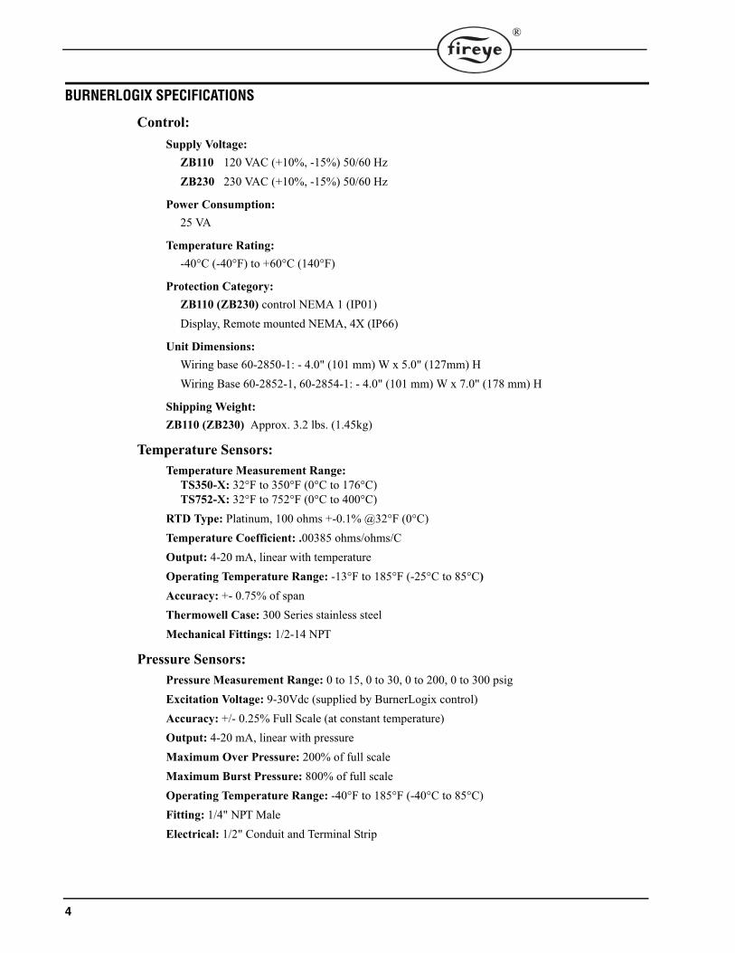
BURNERLOGIX SPECIFICATIONS
Control:Supply Voltage:
ZB110 120 VAC (+10%, -15%) 50/60 HzZB230 230 VAC (+10%, -15%) 50/60 Hz
Power Consumption: 25 VA
Temperature Rating:-40°C (-40°F) to +60°C (140°F)
Protection Category:ZB110 (ZB230) control NEMA 1 (IP01)Display, Remote mounted NEMA, 4X (IP66)
Unit Dimensions:Wiring base 60-2850-1: - 4.0" (101 mm) W x 5.0" (127mm) HWiring Base 60-2852-1, 60-2854-1: - 4.0" (101 mm) W x 7.0" (178 mm) H
Shipping Weight:ZB110 (ZB230) Approx. 3.2 lbs. (1.45kg)
Temperature Sensors:Temperature Measurement Range:
TS350-X: 32°F to 350°F (0°C to 176°C)TS752-X: 32°F to 752°F (0°C to 400°C)
RTD Type: Platinum, 100 ohms +-0.1% @32°F (0°C)Temperature Coefficient: .00385 ohms/ohms/COutput: 4-20 mA, linear with temperatureOperating Temperature Range: -13°F to 185°F (-25°C to 85°C)Accuracy: +- 0.75% of spanThermowell Case: 300 Series stainless steelMechanical Fittings: 1/2-14 NPT
Pressure Sensors:Pressure Measurement Range: 0 to 15, 0 to 30, 0 to 200, 0 to 300 psigExcitation Voltage: 9-30Vdc (supplied by BurnerLogix control)Accuracy: +/- 0.25% Full Scale (at constant temperature)Output: 4-20 mA, linear with pressureMaximum Over Pressure: 200% of full scaleMaximum Burst Pressure: 800% of full scaleOperating Temperature Range: -40°F to 185°F (-40°C to 85°C)Fitting: 1/4" NPT MaleElectrical: 1/2" Conduit and Terminal Strip

5
®
OPERATING TEMPERATURE LIMITS
LOAD RATINGS:
Combination of fuel and igniter terminals
Composition of each combination
Maximum connected load not to exceed 2000 VA
CONTROL MAXIMUM MINIMUM
ZB110/ ZB230 140°F 60°C -40°F -40°C
YP Programmers 140°F 60°C -40°F -40°C
BLV512, VFD Display 140°F 60°C -40°F -40°C
BLL510, LCD Display 140°F 60°C -4°F -20°C
Scanner UV1A, UV2, UV8A, UV90, 45UV3 200°F 93°C -40°F -40°C
45UV5-1005, 45UV5-110545UV5-1007, 45UV5-100955UV5-1007, 55UV5-1009
200°F 93°C -40°F -40°C
48PT2 140°F 60°C -40°F -40°C
Flame Rod (Tip 2460°F) 1500°F 816°C -40°F -40°C
TS350-X, TS7525-XTemperature Transducers
185°F 85°C -13°F -25°C
BLPS-15, 30, 200, 300Pressure Transducers
185°F 85°C -40°F -40°C
Humidity: 90% R.H. (Non-condensing)
Terminal Typical Load A. Maximum Rating@120V-50/60 Hz
B. Maximum Rating @230V-50/60 Hz
C. Alternate Rating
M Burner/Blower Motor 9.8 F.L.A. *58 L.R.A.
4.0 F.L.A. *20 L.R.A.
240 VA Pilot Duty (Motor Starter Coil)
10-11-12-X Modulator 125 VA Pilot Duty
A Alarm 50 VA Pilot Duty
Terminal ratings may be selected from either column A or C for 120 VAC or from either column B or C for 30 VAC:(select the rating from the column which best applies to the connected load on that terminal).
* F.L.A. = full load amps; L.R.A = locked rotor amps
Combination No. Pilot FuelTrm 6
MainTrm 7
IgnitionTrm 5
Delayed ValveTrm W
1 C E No Load No Load2 B E No Load No Load3 No Load E No Load B4 E E A No Load5 No Load E A E6 D E A No Load7 D D A D8 No Load D A No Load
A B C D E
4.5A Ignition@120 VAC
50 VA Pilot Duty plus 4.5A ignition@
120 VAC
180 VA Ignition plus motor valves with: 660
VA inrush, 360 VA open, 250 VA hold.
2A Pilot Duty
@120 VAC
65 VA Pilot Duty plus Motor valves with:
3850 VA inrush, 700 VA open 250 VA hold.2.2A Ignition
@230 VAC50 VA Pilot Duty plus 2.2A ignition
@230 VAC
1A Pilot Duty
@230 VAC
6
®
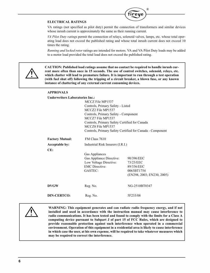
ELECTRICAL RATINGSVA ratings (not specified as pilot duty) permit the connection of transformers and similar deviceswhose inrush current is approximately the same as their running current.VA Pilot Duty ratings permit the connection of relays, solenoid valves, lamps, etc. whose total oper-ating load does not exceed the published rating and whose total inrush current does not exceed 10times the rating.Running and locked rotor ratings are intended for motors. VA and VA Pilot Duty loads may be addedto a motor load provided the total load does not exceed the published rating.
APPROVALSUnderwriters Laboratories Inc.:
MCCZ File MP1537Controls, Primary Safety - ListedMCCZ2 File MP1537Controls, Primary Safety - ComponentMCCZ7 File MP1537Controls, Primary Safety Certified for CanadaMCCZ8 File MP1537Controls, Primary Safety Certified for Canada - Component
Factory Mutual: FM Class 7610Acceptable by: Industrial Risk Insurers (I.R.I.)CE:
Gas AppliancesGas Appliance Directive: 90/396/EECLow Voltage Directive: 73/23/EECEMC Directive: 89/336/EECGASTEC: 0063BT1754
(EN298, 2003; EN230, 2005)
DVGW Reg. No. NG-2510BT0347
DIN-CERTCO: Reg. No. 5F233/08
CAUTION: Published load ratings assume that no contact be required to handle inrush cur-rent more often than once in 15 seconds. The use of control switches, solenoid, relays, etc.which chatter will lead to premature failure. It is important to run through a test operation(with fuel shut off) following the tripping of a circuit breaker, a blown fuse, or any knowninstance of chattering of any external current consuming devices.
WARNING: This equipment generates and can radiate radio frequency energy, and if notinstalled and used in accordance with the instruction manual may cause interference toradio communications. It has been tested and found to comply with the limits for a Class Acomputing device pursuant to Subpart J of part 15 of FCC Rules, which are designed toprovide reasonable protection against such interference when operated in a commercialenvironment. Operation of this equipment in a residential area is likely to cause interferencein which case the user, at his own expense, will be required to take whatever measures whichmay be required to correct the interference.

7
®
PART NUMBERS AND APPROVALS
APPLICABLE BULLETINS
Table 1: Agency Approvals
BurnerLogixChassis/Flame Amp. Module
ZB110UV X X X X X XZB110UVSC X X X X X X
ZB110IR X X X X X XZB230UV X X X
ZB230UVSC X X XZB230IR X X X
BurnerLogix Programmer Module
YP100 X X XYP102 X X XYP138 X X XYP118 X X XYP113 X X X X X X
BurnerLogix Displays
BLV512 X X X X X XBLL510 X X X X X X
BurnerLogix Wiring Bases
60-2850-1 X X X X X60-2852-1 X X X X X60-2854-1 X X X X X
X = CERTIFICATION IN HAND
Programmers, Non-recycle Operation
YP-1001Programmers, Recycle Operation
Programmers, Non-modulating
Displays BD-5001
Wiring base installation, 60-2850-1 133-701
Wiring base installation, 60-2852-1 133-702
Wiring base installation, 60-2854-1 133-702
Pressure/Temperature Sensors BLZPTS-1
Interlock Expansion Module YZEM-3001
APPROVED
8
®
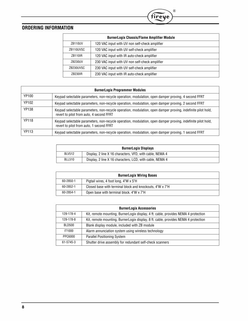
ORDERING INFORMATION
BurnerLogix Chassis/Flame Amplifier Module
ZB110UV 120 VAC input with UV non self-check amplifier
ZB110UVSC 120 VAC input with UV self-check amplifier
ZB110IR 120 VAC input with IR auto-check amplifier
ZB230UV 230 VAC input with UV non self-check amplifier
ZB230UVSC 230 VAC input with UV self-check amplifier
ZB230IR 230 VAC input with IR auto-check amplifier
BurnerLogix Programmer Modules
YP100 Keypad selectable parameters, non-recycle operation, modulation, open damper proving, 4 second FFRT
YP102 Keypad selectable parameters, non-recycle operation, modulation, open damper proving, 2 second FFRT
YP138 Keypad selectable parameters, non-recycle operation, modulation, open damper proving, indefinite pilot hold, revert to pilot from auto, 4 second FFRT
YP118 Keypad selectable parameters, non-recycle operation, modulation, open damper proving, indefinite pilot hold, revert to pilot from auto, 1 second FFRT
YP113 Keypad selectable parameters, non-recycle operation, modulation, open damper proving, 1 second FFRT
BurnerLogix Displays
BLV512 Display, 2 line X 16 characters, VFD, with cable, NEMA 4BLL510 Display, 2 line X 16 characters, LCD, with cable, NEMA 4
BurnerLogix Wiring Bases
60-2850-1 Pigtail wires, 4 foot long, 4"W x 5"H60-2852-1 Closed base with terminal block and knockouts, 4"W x 7"H60-2854-1 Open base with terminal block. 4"W x 7"H
BurnerLogix Accessories
129-178-4 Kit, remote mounting, BurnerLogix display, 4 ft. cable, provides NEMA 4 protection129-178-8 Kit, remote mounting, BurnerLogix display, 8 ft. cable, provides NEMA 4 protection
BLD500 Blank display module, included with ZB moduleIT1000 Alarm annunciation system using wireless technology
PPC6000 Parallel Positioning System61-5745-3 Shutter drive assembly for redundant self-check scanners
9
®
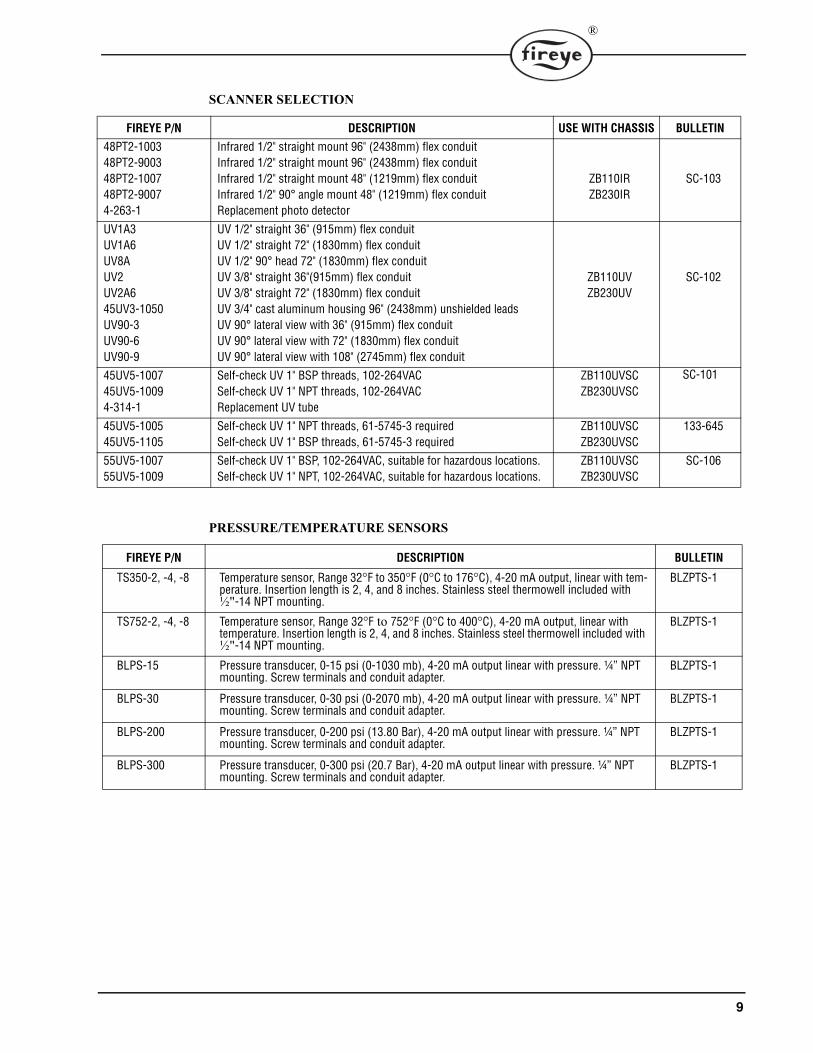
SCANNER SELECTION
PRESSURE/TEMPERATURE SENSORS
FIREYE P/N DESCRIPTION USE WITH CHASSIS BULLETIN
48PT2-100348PT2-900348PT2-100748PT2-90074-263-1
Infrared 1/2" straight mount 96" (2438mm) flex conduitInfrared 1/2" straight mount 96" (2438mm) flex conduitInfrared 1/2" straight mount 48" (1219mm) flex conduitInfrared 1/2" 90° angle mount 48" (1219mm) flex conduitReplacement photo detector
ZB110IRZB230IR
SC-103
UV1A3UV1A6UV8AUV2UV2A645UV3-1050UV90-3UV90-6UV90-9
UV 1/2" straight 36" (915mm) flex conduitUV 1/2" straight 72" (1830mm) flex conduitUV 1/2" 90° head 72" (1830mm) flex conduitUV 3/8" straight 36"(915mm) flex conduitUV 3/8" straight 72" (1830mm) flex conduitUV 3/4" cast aluminum housing 96" (2438mm) unshielded leadsUV 90° lateral view with 36" (915mm) flex conduitUV 90° lateral view with 72" (1830mm) flex conduitUV 90° lateral view with 108" (2745mm) flex conduit
ZB110UVZB230UV
SC-102
45UV5-100745UV5-10094-314-1
Self-check UV 1" BSP threads, 102-264VACSelf-check UV 1" NPT threads, 102-264VACReplacement UV tube
ZB110UVSCZB230UVSC
SC-101
45UV5-100545UV5-1105
Self-check UV 1" NPT threads, 61-5745-3 requiredSelf-check UV 1" BSP threads, 61-5745-3 required
ZB110UVSCZB230UVSC
133-645
55UV5-100755UV5-1009
Self-check UV 1" BSP, 102-264VAC, suitable for hazardous locations.Self-check UV 1" NPT, 102-264VAC, suitable for hazardous locations.
ZB110UVSCZB230UVSC
SC-106
FIREYE P/N DESCRIPTION BULLETIN
TS350-2, -4, -8 Temperature sensor, Range 32°F to 350°F (0°C to 176°C), 4-20 mA output, linear with tem-perature. Insertion length is 2, 4, and 8 inches. Stainless steel thermowell included with ½"-14 NPT mounting.
BLZPTS-1
TS752-2, -4, -8 Temperature sensor, Range 32°F to 752°F (0°C to 400°C), 4-20 mA output, linear with temperature. Insertion length is 2, 4, and 8 inches. Stainless steel thermowell included with ½"-14 NPT mounting.
BLZPTS-1
BLPS-15 Pressure transducer, 0-15 psi (0-1030 mb), 4-20 mA output linear with pressure. ¼” NPT mounting. Screw terminals and conduit adapter.
BLZPTS-1
BLPS-30 Pressure transducer, 0-30 psi (0-2070 mb), 4-20 mA output linear with pressure. ¼” NPT mounting. Screw terminals and conduit adapter.
BLZPTS-1
BLPS-200 Pressure transducer, 0-200 psi (13.80 Bar), 4-20 mA output linear with pressure. ¼” NPT mounting. Screw terminals and conduit adapter.
BLZPTS-1
BLPS-300 Pressure transducer, 0-300 psi (20.7 Bar), 4-20 mA output linear with pressure. ¼” NPT mounting. Screw terminals and conduit adapter.
BLZPTS-1

10
®
WIRING BASE60-2850-1PRE-WIRED4 FOOTCOLOR CODED
FRONT VIEW(WITH OPTIONAL DISPLAY INSTALLED)
WIRING BASE60-2854-1OPEN BOTTOMCABINET MOUNT
60-2852-1CLOSED BOTTOMCONDUIT KNOCKOUT
60-2854-1 SHOWN
CHASSIS/AMPLIFIER
120 VAC, 50/60 HzZB110UVZB110UVSCZB110IR
230 VAC, 50/60 HzZB230UVZB230UVSCZB230IR
PROGRAMMER MODULE
YP100YP102YP113YP138YP118
DISPLAY MODULE
BLV512 - VACUUM FLUORESCENTBLL510 - LIQUID CRYSTAL
(WITH OPTIONAL PROGRAMMER AND DISPLAY INSTALLED)SIDE VIEW

11
®
INSTALLATION PROCEDURE
WIRING BASE
Install the wiring base where the relative humidity never reaches the saturation point. The Burner-Logix system is designed to operate in a maximum 90% relative humidity continuous, non-condens-ing environment. Do not install the BurnerLogix system where it can be subjected to vibration inexcess of 0.5G continuous maximum vibration. The BurnerLogix system is not a weather tightenclosure. The standard vertical position is recommended. Allow at least one inch clearance aroundthe control for service and installation.1. Wiring must comply with all applicable codes, ordinances and regulations.2. Wiring must comply with NEC Class 1 (Line Voltage) wiring. 3. Limits and interlocks must be rated to simultaneously carry and break current to the ignition
transformer, pilot valve and main fuel valve(s).4. Recommended wire routing of lead wires:
a. Do not run high voltage ignition transformer wires in the same conduit with any otherwires.b. Do not route flame detector lead wires in conduit with line voltage circuits. Use separateconduit where necessary.
5. Maximum wire lengths:a. The maximum lead wire length is 200 ft. (61 meters) to terminal inputs (Operating limits,interlocks, valves, etc.).b. Flame Detector lead wires: see section on flame scannersc. Remote reset: The maximum length of wire is 500 feet (152 meters) to a normally openremote reset push-button, but should remain within sight and sound of the burner.d. Modbus communications: The maximum cable length of wire is 3300 feet (1000 meters)for RS-485.
A good ground system should be provided to minimize the effects of AC quality problems. A prop-erly designed ground system meeting all the safety requirements will ensure that any AC voltagequality problems, such as spikes, surges and impulses have a low impedance path to ground. A lowimpedance path to ground is required to ensure that large currents involved with any surge voltageswill follow the desired path in preferences to alternative paths, where extensive damage may occurto equipment.Select either the pre-wired wiring base (60-2850-1) or terminal block style (60-2852-1, 60-2854-1).Either wiring base type can be mounted on a din rail or directly mounted to the cabinet back plate.Refer to Figure 3 for mounting dimensions.
FIGURE 1.
The location should be free from excessive vibration and within the ambient temperature rating.
HEIGHT WITH CONTROL INSTALLED IS 5.8" (147MM)

12
®
FIGURE 2. WIRING BASE CONNECTIONS (shown for 120 VAC)
UL does not apply to 230 VAC operations
Terminal No.60-2852-160-2854-1
Wire Color60-2850-1
Type Description Rating
L1 (Hot) Black Line voltage supply 120 VAC (+10%, -15%), 50/60 Hz
L2 (Neutral) White Line voltage common
EARTH Green Ground
S1 Red/Wht Scanner Input 300 VAC, 3 mA (UV models)15 VDC (IR models)
S2 Blu/Wht Scanner Input 300 VAC, 3 mA (UV models)0 VDC (IR models)
A Red Output Alarm 120 VAC, 1 A pilot duty
M Brown Output Combustion Blower 120 VAC, 9.8 FLA, 58.8 LRA
3 Yellow Input Operating Control 120 VAC, 1 mA
13 Orange Input Fuel Valve End Switch, Pre-Ignition Interlock
120 VAC, 1 mA
P Gray Input Running Interlock 120 VAC, 1 mA
D Wht/Brn Input Low Fire Start Switch 120 VAC, 1 mA
8 Wht/Gry Input Open Damper Proving Switch 120 VAC, 1 mA
W Wht/Orn Output Delayed Main Valve See Load Ratings
5 LT Blue Output Ignition / Pilot Valve See Load Ratings
6 Tan Output Pilot Valve See Load Ratings
7 Violet Output Main Fuel Valve See Load Ratings
16 DK Blue Input Lag 1 Input See description for alternate uses21 Pink Input Lag 2 Input
LOW VOLTAGE INPUT/OUTPUT
12 Wht/Yel Output Modulator Drive Positive 4-20mA Output
10 Wht/Red Output Modulator Drive Common
X Wht/Blue Output Temp/Pressure Source Voltage 28 vdc Nominal
11 Wht/Grn Input Temp/Pressure #1 (PCV) 4-20mA Input, Primary Control Variable
22 Wht/Vio Input Temp/Pressure #2 (AUX 1) 4-20mA Input
23 Brn/Wht Input Temp/Pressure #3(AUX 2) 4-20mA Input

13
®
PRESSURE AND TEMPERATURE SENSORS
1. Insure that the range of the selected pressure or temperature sensor is appropriate for the application. See Table 2
Table 2:
2. Note: A general rule to follow when selecting the sensor range is that the expected value of themonitored pressure or sensor should fall between 40-70% of the upper range of the sensor. Forexample, a steam boiler maintains 20 lbs. pressure, select the BLPS-30 Pressure Sensor, with a0-30 psig range.
3. The sensors must be located where the ambient temperature will not exceed the maximum ambi-ent operating temperature specified for the sensor.
4. Insure that the pressure range programmed on the BurnerLogix Z Control matches the installedpressure sensor.
5. Do not mount any of the sensors where they could be used as a footstep.Installation must be performed by a trained, experienced flame safeguard technician.
MOUNTING PRESSURE SENSORSNote: refer to Figure 31. The steam pressure sensors (BLPS-15, -30, -200, -300) provide a 1/4" NPT female fitting for
connection to the steam header.2. Make sure the boiler is shut down and zero steam pressure exists in the boiler vessel.3. Disconnect power to the boiler controller so the boiler cannot sequence during installation of the
steam pressure sensor.4. Always mount the steam pressure sensor above the water line of the boiler.5. Locate the pressure sensors where the ambient temperature will not exceed 185F6. Use only a small amount of pipe compound to seal the connection joints. Excess pipe compound
may clog the fitting and prevent proper operation of the sensor.
Part Number Sensor Type Set Point Range Cut In Cut Out Mod Range Increment
Decrement
0 - 15 psi 1.0 - 14.0p 0 - 6.0p 0.3 - 6.0p 0.3 - 6.0p 0.1p0 - 1030m 70m - 950m 0 - 410m 20m - 410m 20m - 410m 10m
0 - 30 psi 1.0 - 28.0p 0 - 6.0p 0.3 - 6.0p 0.3 - 6.0p 0.1p0 - 2070m 70m - 1950m 0 - 410m 20m - 410m 20m - 410m 10m
0 - 200 psi 10 - 190p 0 - 60p 3 - 60p 3 - 60p 1.0p0 - 13.8B 0.70 - 13.0B 0.0 - 4.1B 0.2 - 4.10B 0.20 - 4.10B .05B
0 - 300 psi 10 - 280p 0 - 60p 3 - 60p 3 - 60p 1.0p0 - 20.7B 0.70 - 19.3B 0.0 - 4.1B 0.2B - 4.10B 0.2B - 4.10B .05B
32º - 350ºF 36º - 338ºF 0º - 60ºF 3º - 60ºF 3º - 60ºF 1ºF0º - 176ºC 4º - 170ºC 0º - 60ºC 3º - 60ºC 3º - 60ºC 1ºC
32º - 752ºF 36º - 725ºF 0º - 60ºF 3º - 60ºF 3º - 60ºF 1ºF0º - 400ºC 4º - 385ºC 0º - 60ºC 3º - 60ºC 3º - 60ºC 1ºC
BLPS-15
BLPS-30
BLPS-200
BLPS-300
m = milibar, p = psi
Note: 1 psi = 68.94757 mbar
TS350-X*
TS752-X*
*Select Length X = -2”, -4” or -8”

14
®
FIGURE 3.
7. Although the unit can withstand substantial vibration without damage or significant outputeffects, it is good practice to mount the pressure sensor where there is minimum vibration.
8. A steam trap (siphon loop) must be connected between the boiler and the pressure sensor to pre-vent boiler scale and corrosive vapors from affecting the pressure sensor element.
9. Make all pipe connections in accordance with approved standards.10. When tightening the sensor, apply a wrench to the hex flats located just above the pressure fit-
ting. DO NOT tighten by using a pipe wrench on the housing. Do not tighten the pressure sensorby hand.
.
MOUNTING TEMPERATURE SENSORSThe immersion style temperature sensors have a ½" NPT mounting for the 2", 4", and 8" thermowellprobes, and a ½" conduit fitting for electrical connections.
HOT WATER, STANDBY WATER TEMPERATURENote: Refer to Figure 31. Disconnect power to the boiler controller so the boiler cannot sequence during installation of the
hot water temperature sensor.2. The thermowell must be mounted where it is always exposed to the circulation of the hot water.3. If the water system is full, drain the system below the point where the thermowell will be
installed.4. Tap an appropriate size fitting. (2", 4" and 8" thermowell have ½" NPT fitting).5. Insert the appropriate thermowell (2", 4", or 8") and tighten.6. Fill the system to check for leakage.
STACK TEMPERATURE1. Use the existing well connection for the stack temperature sensor if provided by the boiler
manufacturer.
WARNING: The electro-mechanical high steam limit and/or high hot water temperatureMUST REMAIN in the 3-P running interlock circuit.
WARNING: Location of the temperature sensor to monitor boiler water temperature of asteam boiler is critical. The sensor should be mounted where it is always exposed to the cir-culation of the boiler water, not too close to a hot or cold inlet or steam coil. Consult theboiler manufacturer for guidance on the sensor location

15
®
2. If no well connection is provided, select an appropriate location for mounting the temperaturesensor. Preferably as close to the boiler outlet as possible.
OUTDOOR TEMPERATURE1. The outdoor air temperature sensor should be mounted on the outside of the building where it
will be exposed to representative air temperature, but not to direct sunlight. A sun shield may berequired.
2. Mount the temperature sensor high enough so it cannot be covered with snow, leaves, or otherdebris, or be tampered with. Vents from the building should be avoided
WIRING PRESSURE AND TEMPERATURE SENSORS
1. All wiring must be in accordance with National Electrical Code and local codes, ordinances, andregulations.
2. Sensor housing provides connection for 1/2" conduit.3. The pressure and temperature sensors require 2 conductor, 18 gauge, shielded cable. Power lim-
ited, rated for 300V @105C. Use Belden 9318 or equivalent.4. The shield should be connected to the earth ground terminal on the wiring base of the Burner-
Logix Control (Terminal #E). The shield should be taped at the sensor to avoid unintended con-tact with the sensor housing.
5. All sensor wiring should be in a separate conduit. DO NOT install sensor wiring in any conduitor junction boxes with high voltage wiring.
6. Maximum wiring distance for sensor wiring is 100 feet.7. See following chart for wiring terminations:
WIRING FIRING RATE MOTOR1. All wiring must be in accordance with National Electrical Code and local codes, ordinances, and
regulations.2. For 4-20 mA motors, use 2 conductor, 18 gauge, shielded cable. Power limited, rated for 300V
@105C. Use Belden 9318 or equivalent.3. The shield should be connected to the earth ground terminal on the wiring base of the Burner-
Logix Control (Terminal #E). The shield should be taped at the motor to avoid unintended con-tact with the motor housing.
4. All wiring should be in a separate conduit. DO NOT install wiring in any conduit or junctionboxes with high voltage wiring.
5. Maximum wiring distance for sensor wiring is 100 feet.
TS350/TS752 BLPS PVC AUX1 AUX2
1 +EXC X (WHT/BLU) X (WHT/BLU) X (WHT/BLU)2 -COM 11 (WHT/GRN) 22 WHT/VIO) 23 (BRN/WHT)
CAUTION: Disconnect power supply from the BurnerLogix Control before connectingwires to prevent electrical shock and equipment damage.
CAUTION: PROGRAM AND SET-UPThe proper operation of the BurnerLogix System and the pressure and temperature sensorsrequire that the selected pressure ranges are appropriate for the application and mustmatch the pressure range programmed on the BurnerLogix Control. Insure that the rangeof the selected sensor is correct for the application and pressure range matches the installedpressure sensor.
16
®
BEFORE INSTALLING THE BURNERLOGIX CONTROL
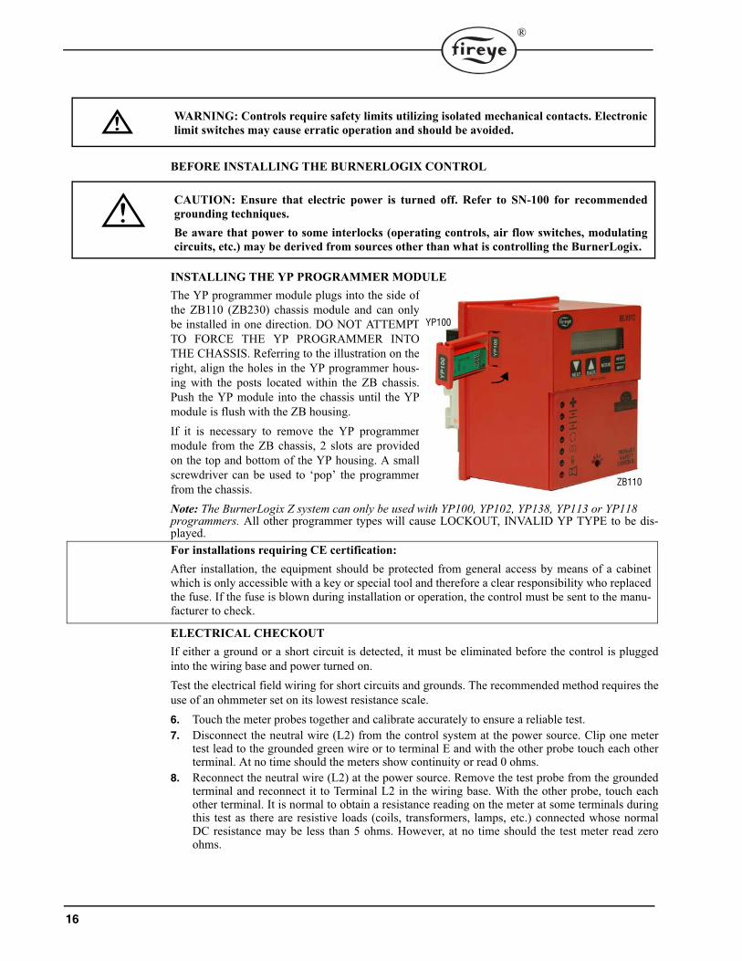
INSTALLING THE YP PROGRAMMER MODULEThe YP programmer module plugs into the side ofthe ZB110 (ZB230) chassis module and can onlybe installed in one direction. DO NOT ATTEMPTTO FORCE THE YP PROGRAMMER INTOTHE CHASSIS. Referring to the illustration on theright, align the holes in the YP programmer hous-ing with the posts located within the ZB chassis.Push the YP module into the chassis until the YPmodule is flush with the ZB housing.If it is necessary to remove the YP programmermodule from the ZB chassis, 2 slots are providedon the top and bottom of the YP housing. A smallscrewdriver can be used to ‘pop’ the programmerfrom the chassis.Note: The BurnerLogix Z system can only be used with YP100, YP102, YP138, YP113 or YP118 programmers. All other programmer types will cause LOCKOUT, INVALID YP TYPE to be dis-played.For installations requiring CE certification:After installation, the equipment should be protected from general access by means of a cabinetwhich is only accessible with a key or special tool and therefore a clear responsibility who replacedthe fuse. If the fuse is blown during installation or operation, the control must be sent to the manu-facturer to check.
ELECTRICAL CHECKOUTIf either a ground or a short circuit is detected, it must be eliminated before the control is pluggedinto the wiring base and power turned on.Test the electrical field wiring for short circuits and grounds. The recommended method requires theuse of an ohmmeter set on its lowest resistance scale.6. Touch the meter probes together and calibrate accurately to ensure a reliable test.7. Disconnect the neutral wire (L2) from the control system at the power source. Clip one meter
test lead to the grounded green wire or to terminal E and with the other probe touch each otherterminal. At no time should the meters show continuity or read 0 ohms.
8. Reconnect the neutral wire (L2) at the power source. Remove the test probe from the groundedterminal and reconnect it to Terminal L2 in the wiring base. With the other probe, touch eachother terminal. It is normal to obtain a resistance reading on the meter at some terminals duringthis test as there are resistive loads (coils, transformers, lamps, etc.) connected whose normalDC resistance may be less than 5 ohms. However, at no time should the test meter read zeroohms.
WARNING: Controls require safety limits utilizing isolated mechanical contacts. Electroniclimit switches may cause erratic operation and should be avoided.
CAUTION: Ensure that electric power is turned off. Refer to SN-100 for recommendedgrounding techniques.Be aware that power to some interlocks (operating controls, air flow switches, modulatingcircuits, etc.) may be derived from sources other than what is controlling the BurnerLogix.
ZB110
YP100

17
®
9. With BurnerLogix installed, measure voltage from L2 to all other terminals. Reading should bezero on all terminals except Ll.
INSTALL BURNERLOGIX INTO WIRING BASEThe BurnerLogix ZB chassis/amplifier module contains 2 screws permanently retained into the topand bottom of the housing. The wiring base contains two brass inserts with recessed threads to easethe installation. Line up the printed circuit board spacer located in the ZB chassis/amplifier modulewith the alignment tabs located in the wiring base. Firmly push the ZB model into the wiring base toassure the connectors mate properly. Tighten the screws into the brass inserts until snug.
REPLACEABLE FUSE
The following applies only to the ZB110 controls operating at 120 VAC, 50/60 Hz:The chassis/amplifier modules are designed with a field replaceable fuse to protect Terminals 5, 6, 7and W against short circuit loads or mis-wiring. In the event the fuse becomes OPEN, the displaywill indicate CHECK FUSE or the CLOSE DAMPER, AUTO and IGN LED’s will light. An OPENor blown fuse is a result of an over current condition on Terminals 5, 6, 7, or W. The over currentcondition causing the fuse to OPEN must be resolved before another attempt to apply power.For installations requiring CE certification:Only Fireye or a Fireye trained technician is allowed to replace the fuse.All other installations:The fuse is located on the printed circuit board containing the relays. To replace the fuse, removepower from the system and remove the control from its wiring base. Using an appropriate tool,remove the defective fuse and discard. Install a Fireye replacement fuse (P/N 23-197) or equivalent10 amp fuse (e.g. Wickman # 1937-071-K). Re-install the BurnerLogix control in accordance withthe installation procedure detailed in a previous section.The ZB230 control contains a non-replaceable fuse and must be returned to the manufacturer forrepair or replacement.
BURNERLOGIX PROGRAMMER SELECTION
All programmers for the BurnerLogix Series are designated with the prefix “YP”. The functionaloperation, flame failure response time, purge timings, firing rate motor circuit, trial for ignition tim-ings, recycling function and display messages are determined by the programmer.A chart of the most common programmers is found below. Take note of the programming sequence chart for each programming module for the proper explana-tion of prepurge timings.
CAUTION: Restore power for the following test.
WARNING: THE INAPPROPRIATE SELECTION OR APPLICATION OF A PRO-GRAMMER MODULE COULD RESULT IN AN UNSAFE CONDITION HAZARDOUSTO LIFE AND PROPERTY. The various programmer modules are interchangeablebecause they plug into a common ZB chassis. Many parameters are configurable throughthe keypad display. Care should be taken to insure the proper parameters are set. Refer tothe appropriate programmer bulletin for appropriate settings. Selection of the programmermodule and setting the various parameters for a particular application should be made by acompetent professional, such as a Boiler/Burner technician licensed by a state or govern-ment agency, engineering personnel of the burner, boiler or furnace manufacturer (OEM)or in the performance of duties based on the information from the OEM.

18
®
PTFI*MTFI TIMINGS
The BurnerLogix system provides keypad selectable timings for both PTFI and MTFI. The selectionsoffered can provide 5 or 10 second timing for terminal 5 and 6 or a shortened time for terminal 5,allowing for early spark termination. BurnerLogix also provides selectable interrupted or intermittentoperation for terminal 6.The selections provided for PTFI*MTFI timings are:
Table 3:
FIREYE PART
NUMBER
Pre-purge Programming
(Seconds)
Proven High Fire Interlock
(M-8)
Proven Low Fire Interlock
(M-D)
Terminal 6, Interrupted
or Intermittent
Early Spark Termination
PTFI(5/6)
MTFI (5/6)
Running Interlock
(3-P)
Flame Fail Time
(Seconds)
Firing Rate Motor
SETTINGS SHOWN ARE FACTORY DEFAULT
YP100 30 YES YES INTRP NO 10/10 10/15 Non-recycle 4 YESYP102 30 YES YES INTRP NO 10/10 10/15 Non-recycle 2 YESYP138 30 YES YES INTRP NO 10/10 10/15 Non-recycle 4 YESYP118 30 YES YES INTRP NO 10/10 10/15 Non-recycle 1 YESYP113 30 YES YES INTRP NO 5/5 3/5 Non-recycle 1 YES
SELECTION PTFI MTFI COMMENT
Term 5 Term 6 Term 5 Term 6
10/10*10/15 10 10 10 155/5*0/10 5 5 0 10 NO SPARK DURING MTFI5/5*0/5 5 5 0 5 NO SPARK DURING MTFI5/5*10/15 5 5 10 15 SHORTENED PTFI5/5*10/10 5 5 10 10 SHORTENED PTFI5/10*0/15 5 10 0 15 EARLY SPARK TERMINATION5/10*0/10 5 10 0 10 EARLY SPARK TERMINATION10/10*0/10 10 10 0 10 NO SPARK DURING MTFI10/10*0/5 10 10 0 5 NO SPARK DURING MTFI10/10*10/10 10 10 10 10
19
®
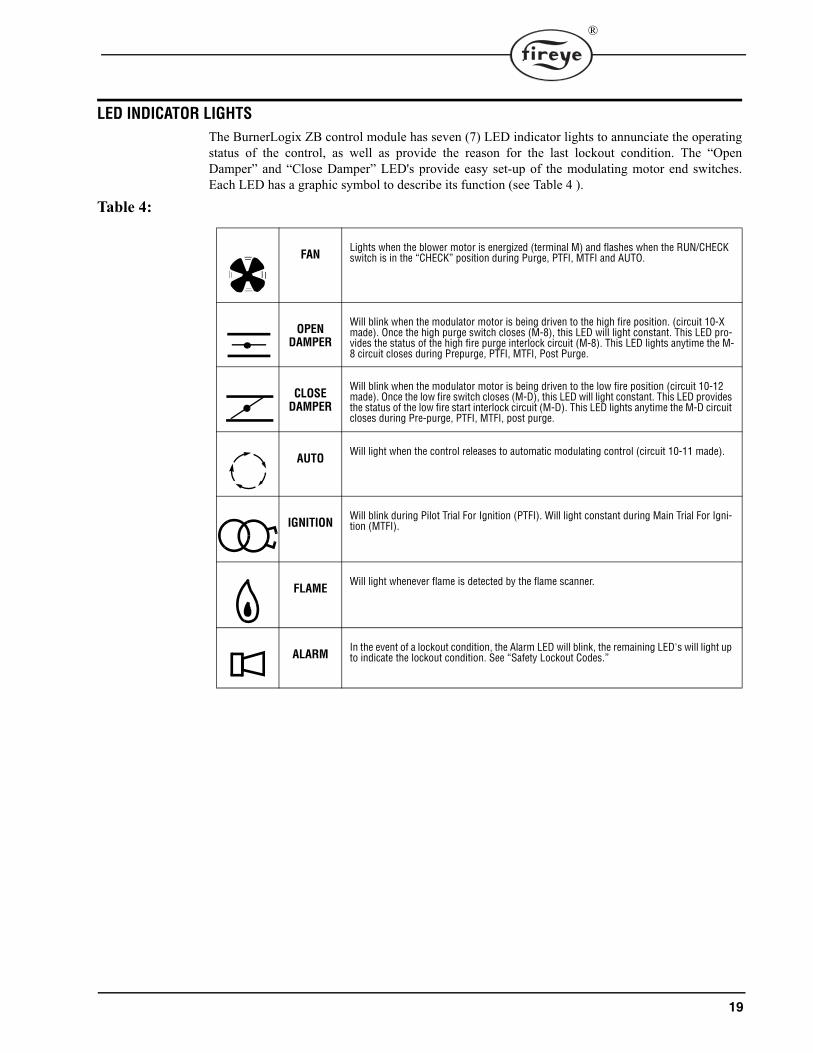
LED INDICATOR LIGHTS
The BurnerLogix ZB control module has seven (7) LED indicator lights to annunciate the operatingstatus of the control, as well as provide the reason for the last lockout condition. The “OpenDamper” and “Close Damper” LED's provide easy set-up of the modulating motor end switches.Each LED has a graphic symbol to describe its function (see Table 4 ).
Table 4:
FANLights when the blower motor is energized (terminal M) and flashes when the RUN/CHECK switch is in the “CHECK” position during Purge, PTFI, MTFI and AUTO.
OPEN DAMPER
Will blink when the modulator motor is being driven to the high fire position. (circuit 10-X made). Once the high purge switch closes (M-8), this LED will light constant. This LED pro-vides the status of the high fire purge interlock circuit (M-8). This LED lights anytime the M-8 circuit closes during Prepurge, PTFI, MTFI, Post Purge.
CLOSE DAMPER
Will blink when the modulator motor is being driven to the low fire position (circuit 10-12 made). Once the low fire switch closes (M-D), this LED will light constant. This LED provides the status of the low fire start interlock circuit (M-D). This LED lights anytime the M-D circuit closes during Pre-purge, PTFI, MTFI, post purge.
AUTOWill light when the control releases to automatic modulating control (circuit 10-11 made).
IGNITIONWill blink during Pilot Trial For Ignition (PTFI). Will light constant during Main Trial For Igni-tion (MTFI).
FLAMEWill light whenever flame is detected by the flame scanner.
ALARMIn the event of a lockout condition, the Alarm LED will blink, the remaining LED's will light up to indicate the lockout condition. See “Safety Lockout Codes.”

20
®
DESCRIPTION OF FUNCTIONS OF OPERATING CONTROLS
1. Operating Controls: Generally pressure or temperature activated, the operating control closes,causing the burner start-up sequence to begin. When the operating control opens, the burnershuts off. The operating control is connected in the L1-3 circuit on the wiring base.
2. Limit Switches: These are generally pressure, water level or temperature activateda. Recycle — when it is desired to stop the burner when the limit switch opens and restart itwhen the limit switch recloses, they are connected between Terminals L1 and 3.b. Non-Recycle —when it is necessary to stop the burner when the limit switch opens and pre-vent it from starting until both the limit switch recloses and the manual reset is activated, theyare connected between terminals 3 and P.
3. Fuel Valve End Switch Interlock: This is generally an integral switch mounted on the mainfuel valve and activated by the valve stem. It is connected between Terminal L1 & 13. The fuelvalve end switch interlock prevents a burner start-up if the valve stem is not in the “valveclosed” position. This interlock must remain closed while in STANDBY and until the start ofPTFI.
4. Purge Interlock: Generally a firing rate motor linkage position switch or a differential air-pres-sure switch, that proves a maximum purge air flow rate. It is connected between Terminals Mand 8. The purge interlock proves that the air damper is fully open and purge air flow rate is atmaximum during the purge.
5. Running Interlocks: These generally are air flow switches, high and low fuel pressureswitches, oil temperature switches, atomizing media pressure switches, and excess smoke den-sity controls. These interlocks prove proper conditions for normal operation of the burner. Theyare wired in series and connected between Terminals 3 and P.
6. Low Fire Start Interlock: Generally a firing rate motor linkage position switch or a damperposition switch, will prove both the linkage and dampers are in their proper positions to beginburner light off. This switch is connected between Terminals M and D.
SETTING PROGRAMMER PARAMETERS
In order to change the factory default parameters stored in the programmer module an optional key-pad/display (BLV512 or BLL510) is required. All configurable parameters are stored within thePROGRAM SETUP sub-menu. The keypad/display module provides tactile feedback keys that areused to access the sub-menus inherent in the BurnerLogix system.
The BurnerLogix display consists of 2 lines having 16 characters per line. The default displayed itemis the current operating status. This would include the current point in the burner sequence followedby the parameter pertaining to that point in the sequence, such as time or the flame signal level. Thebottom line is used to display the current operating status. The BurnerLogix display also provides thehistorical information stored in the control’s memory such as burner hours, cycles, lockouts and sys-tem hours. The remainder of the display items are menus with sub-menus indicated by a right facingarrow. The sub-menus indicate the current value of the selected item and in some cases can be modi-fied to suit the application.
All programmed safety times and interlock configuration settings become permanent after 8 hours of main burner (Terminal 7) on time. (This does not apply to Boiler Parms).
STANDBY PROGRAM SETUP >

21
®
Keypad DescriptionThe NEXT key is used to scroll down through the variousmenus and is also used to increment the value when in themodify mode. The BACK key is used to scroll up throughthe menus and is also used to decrement the value when inthe modify mode. The MODE key is used to enter a sub-menu when the displayed item indicates a sub-menu with aright facing arrow and also to exit the sub-menu and moveon to the next main menu item. The RESET/MDFY key is
used to reset the BurnerLogix from a lockout condition, force a recycle of the programmer, indicateto the system the value displayed is to be modified or when done with the modification
FIGURE 4. BURNERLOGIX MAIN MENU STRUCTURE
The BurnerLogix display system is made up of a number of circular menus and within these menusare sub-menus and in some cases further sub-menus within sub-menus. For example, within theBOILER PARMS sub-menu are additional sub-menus needed to set the various parameters forproper boiler operation, see Figure 7. The menus are circular in that continued pressing of the NEXTor BACK keys will eventually land you in the same place that you started. Any menu item that is fol-lowed by the '>' symbol indicates this is a sub-menu and pressing the MODE key will cause entryinto the sub-menu. Pressing the MODE key from anywhere within a sub-menu will cause exit fromthe sub-menu and the next item from the previous menu will be displayed.
START HERE
Scrolls through menu, clockwise
Keypad Legend
PROGRAM SETUP >
SYS HOURS
STANDBY
L1 - 3 OPEN
MODE STANDBYPROGRAMMER YP100
LOCKOUT HISTORY >
MODE LO #XX PTFI
SYSTEM INFO >
MODE STANDBYAVG. PILOT FLM. 42
NEXT
Scrolls through menu, counter-clockwiseBACK
MODE
Provides reset of control if lockout
MODIFY
RESET
Provides access to Sub-menu or
Provides recycle of control
Allows parameter to be modified/saved
FLAME FAILSTANDBY
8.4p AUTO 0%
8.4p AUTO 0%
LEAD FLM 0
8.4p AUTO 0%
AUX 1 UNUSED
8.4p AUTO 0%
AUX 2 UNUSED
BNR HOURS
BOILER PARMS>
MODE MODIFY TO CHANGE UNITS OF MEASURE
BNR CYCLES
PRESS
PRESS
PRESS
PRESS
Exits Sub-Menu
BNR LOCKOUTS
See Note 1
Note 1:
ALL-INFO SCREEN
See page 24 for details.

22
®
PROGRAM SET UP SUB-MENU
The sub-menu "PROGRAM SETUP" allows the user to review the various operational settings ofthe programmer module (e.g. programmer type, purge timing, etc.) and some instances modify theoperational parameters to suit the application requirement. The MODE key is used to enter and exitthe sub-menu and the NEXT and BACK keys are used to scroll through the menu as well as changethe operational parameter.
FIGURE 5.
TO VIEW AND MODIFY A PROGRAMMABLE PARAMETER:
Use the NEXT or BACK key to scroll to PROGRAM SETUP see Figure 4. Press the MODE key toenter the sub-menu showing all program setup parameters. Pressing the MODE key while in the sub-menu will exit the sub-menu, and the next main menu item will be displayed. While in the sub-menu,pressing the NEXT key will scroll forward through the sub-menu. Pressing the BACK key will scrollbackward through the sub-menu. When a modifiable parameter is displayed, the top line will indicateMDFY TO CHANGE while the bottom line will indicate the current item and its current value.Pressing the RESET/MDFY key will allow the displayed parameter to be modified. The item to bemodified will move to the top line while its value will remain on the bottom line. At an infrequentrate, the top line will indicate MDFY TO SAVE. Use the NEXT or BACK keys to select the value tosuit the application and when done, press the RESET/MDFY to save the value to memory.
PMDFY TO CHANGE
FLM FAIL TIME 4 SEC
AMP IR
PROGRAMMER YP100
DO IR LEARN NO
LOCK SETTINGS NO
START HERE
MODE
PROVE 3-P OPEN N
MDFY TO CHANGE
COUNT METHOD DOWN
MDFY TO CHANGE
PURGE 0:30
UNIT ADDRESS 1
BAUD RATE 9600
PROVE M-D TFI NO
M-D WAIT 10m YES
POST PURGE 0:15
PROVE M-D OPEN NO
PROVE M-8 OPEN NO
TERMINAL 6 INTRP
PTFI * MTFI TIMING
FROM
MAIN
MENU LOOP
PRESS KEY FROM MAIN MENU LOOP
MODEPRESS KEY AT ANYTIME TO EXIT SUB-MENU
Note:ZB110IR only
23
®
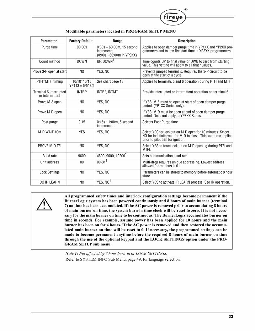
Modifiable parameters located in PROGRAM SETUP MENU
Note 1: Not affected by 8 hour burn-in or LOCK SETTINGS.Refer to SYSTEM INFO Sub Menu, page 49, for language selection.
Parameter Factory Default Range Description
Purge time 00:30s 0:30s – 60:00m, 15 second increments.(0:00s - 60:00m in YP3XX)
Applies to open damper purge time in YP1XX and YP2XX pro-grammers and to low fire start time in YP3XX programmers.
Count method DOWN UP, DOWN1 Time counts UP to final value or DWN to zero from starting value. This setting will apply to all timer values.
Prove 3-P open at start NO YES, NO Prevents jumped terminals. Requires the 3-P circuit to be open at the start of a cycle.
PTFI*MTFI timing 10/10*10/15YP113 = 5/5*3/5
See chart page 18 Applies to terminals 5 and 6 operation during PTFI and MTFI.
Terminal 6 interrupted or intermittent
INTRP INTRP, INTMT Provide interrupted or intermittent operation on terminal 6.
Prove M-8 open NO YES, NO If YES, M-8 must be open at start of open damper purge period. (YP1XX Series only).
Prove M-D open NO YES, NO If YES, M-D must be open at end of open damper purge period. Does not apply to YP3XX Series.
Post purge 0:15 0:15s - 1:00m, 5 second increments.
Selects Post Purge time.
M-D WAIT 10m YES YES, NO Select YES for lockout on M-D open for 10 minutes. Select NO for indefinite wait for M-D to close. This wait time applies prior to pilot trial for ignition.
PROVE M-D TFI NO YES, NO Select YES to force lockout on M-D opening during PTFI and MTFI.
Baud rate 9600 4800, 9600, 192001 Sets communication baud rate.
Unit address 00 00-311 Multi-drop requires unique addressing. Lowest address allowed for modbus is 01.
Lock Settings NO YES, NO Parameters can be stored to memory before automatic 8 hour store.
DO IR LEARN NO YES, NO1 Select YES to activate IR LEARN process. See IR operation.
All programmed safety times and interlock configuration settings become permanent if theBurnerLogix system has been powered continuously and 8 hours of main burner (terminal7) on time has been accumulated. If the AC power is removed prior to accumulating 8 hoursof main burner on time, the system burn-in time clock will be reset to zero. It is not neces-sary for the main burner on time to be continuous. The BurnerLogix accumulates burner ontime in seconds. For example, assume power has been applied for 10 hours and the mainburner has been on for 4 hours. If the AC power is removed and then restored the accumu-lated main burner on time will be reset to 0. If necessary, the programmed settings can bemade to become permanent anytime before the required 8 hours of main burner on timethrough the use of the optional keypad and the LOCK SETTINGS option under the PRO-GRAM SETUP sub menu.

24
®
GETTING STARTED
The BurnerLogix Z System performs two main functions, burner management and boiler control.For burner management, the BurnerLogix Z System continuously monitors interlocks and limitsfound in the L1-13, L1-3 and 3-P circuits as it programs the burner/blower motor, ignition and fuelvalves to provide for proper and safe burner operation. For boiler control, the BurnerLogix Z systemcontinuously reads the input pressure or temperature transducer, compares the reading to the appro-priate user programmable setpoint, and adjusts the firing rate to meet output demand.
GENERAL INFORMATION
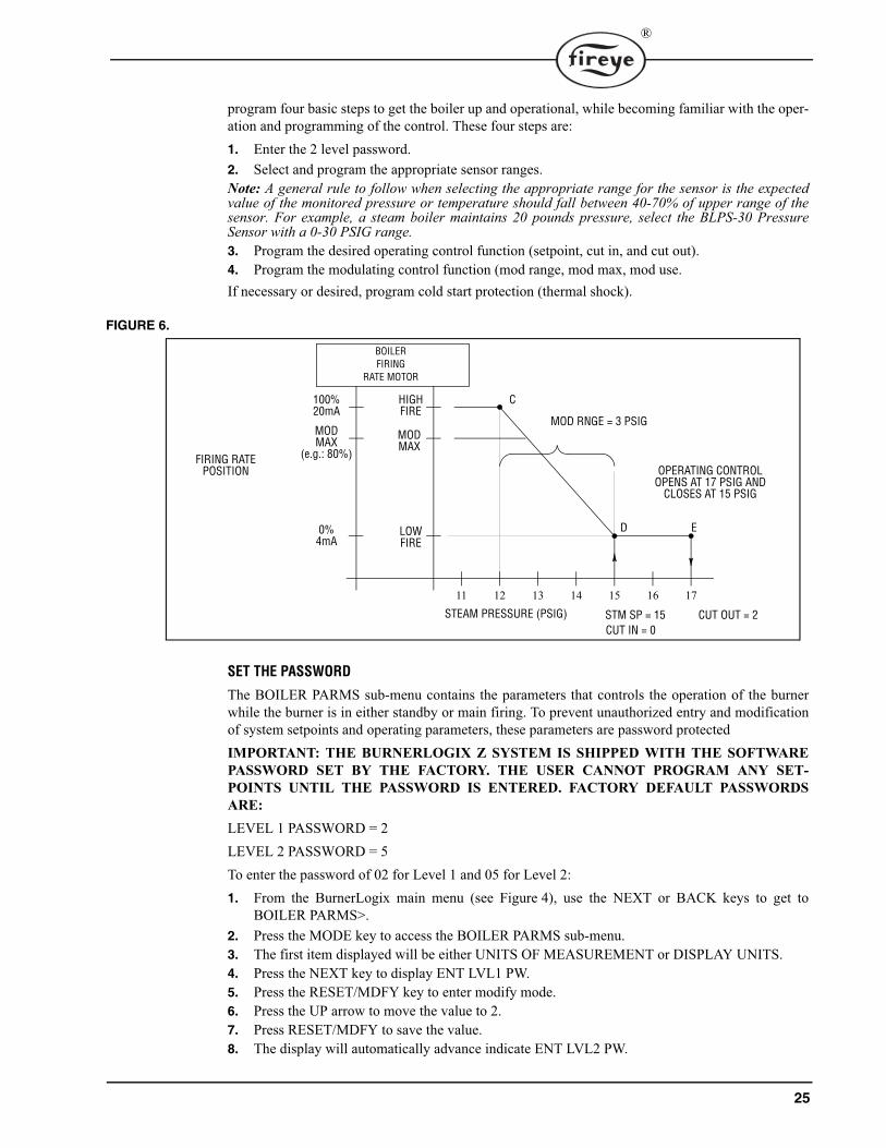
Once the sensor usage and range is selected and programmed, the user then programs the setpointsassociated with the operating control function of the BurnerLogix Z System. These setpoints areSteam Pressure Setpoint (STM STPT) or Water Temperature Setpoint (WTR STPT), Cut In (CUTIN), and Cut Out (CUT OUT) and Modulating Range (MOD RNG). 1. CUT IN Setpoint is a differential value that is subtracted from the Setpoint to determine where
burner startup occurs.2. CUT OUT Setpoint is a differential value that is added to the Setpoint to determine where burner
shutdown occurs. 3. MOD RNG Setpoint is a differential value that is subtracted from the Setpoint and determines
the range over which the firing motor will travel from high fire (100%) to low fire (0%). SeeFigure 5.
This is an indication the mechanical limits (burner on switch, first low water cutoff, etc.) located inthe L1-3 operating control (recycling) circuit are closed but the burner is in a shutdown or standbystate due to the current measured primary control variable reading, pressure or temperature, is abovethe cut in point.
ALL-INFO SCREEN
The BurnerLogix Z control provides all boiler control information as part of one display screenlocated in the main BurnerLogix menu structure. From any burner operating position, the user cansee the current operating temperature or pressure, mod motor usage and firing range position, operat-ing mode and flame signal detected.
While in STANDBY or AUTO mode the ALL-INFO screen becomes the default screen, occurring10 seconds after that state is reached.
Programming/Set-up GuideIncluded with this bulletin is a Programming/Set-up guide see page 77 and page 78 to aid the user inprogramming the control. The set-up sheet lists all of the setpoints associated with the BurnerLogixZ control. The set-up sheet is a valuable tool by providing an overview of what setpoints need to beprogrammed for the various functions, as well as providing a written copy of the setpoints to refer towhen actually programming the setpoints. It also serves as a permanent hard copy record.The BurnerLogix Z requires the user to program a number of operating parameters for proper systemoperation. While the BurnerLogix Z Control offers a number of features and functions, a user can
STANDBY L1-3 CLOSED
8.7P AUTO 36%LEAD FLM 42
PRIMARY CONTROL VARIABLE
OPERATING MODE
MOD MOTOR USAGE FIRING RATE
FLAME SIGNAL
25
®
program four basic steps to get the boiler up and operational, while becoming familiar with the oper-ation and programming of the control. These four steps are:1. Enter the 2 level password.2. Select and program the appropriate sensor ranges.Note: A general rule to follow when selecting the appropriate range for the sensor is the expectedvalue of the monitored pressure or temperature should fall between 40-70% of upper range of thesensor. For example, a steam boiler maintains 20 pounds pressure, select the BLPS-30 PressureSensor with a 0-30 PSIG range.3. Program the desired operating control function (setpoint, cut in, and cut out).4. Program the modulating control function (mod range, mod max, mod use.If necessary or desired, program cold start protection (thermal shock).
FIGURE 6.
SET THE PASSWORD
The BOILER PARMS sub-menu contains the parameters that controls the operation of the burnerwhile the burner is in either standby or main firing. To prevent unauthorized entry and modificationof system setpoints and operating parameters, these parameters are password protected IMPORTANT: THE BURNERLOGIX Z SYSTEM IS SHIPPED WITH THE SOFTWAREPASSWORD SET BY THE FACTORY. THE USER CANNOT PROGRAM ANY SET-POINTS UNTIL THE PASSWORD IS ENTERED. FACTORY DEFAULT PASSWORDSARE:LEVEL 1 PASSWORD = 2LEVEL 2 PASSWORD = 5To enter the password of 02 for Level 1 and 05 for Level 2:1. From the BurnerLogix main menu (see Figure 4), use the NEXT or BACK keys to get to
BOILER PARMS>.2. Press the MODE key to access the BOILER PARMS sub-menu.3. The first item displayed will be either UNITS OF MEASUREMENT or DISPLAY UNITS.4. Press the NEXT key to display ENT LVL1 PW.5. Press the RESET/MDFY key to enter modify mode.6. Press the UP arrow to move the value to 2.7. Press RESET/MDFY to save the value.8. The display will automatically advance indicate ENT LVL2 PW.
LOWFIRE
D E
STEAM PRESSURE (PSIG)
11 12 13 14 15 16 17
MODMAX
CHIGHFIRE
100%20mA
MODMAX
(e.g.: 80%)
0%4mA
MOD RNGE = 3 PSIG
STM SP = 15 CUT OUT = 2CUT IN = 0
BOILERFIRING
RATE MOTOR
OPERATING CONTROLOPENS AT 17 PSIG AND
CLOSES AT 15 PSIG
FIRING RATEPOSITION
26
®
9. Press the RESET/MDFY key to enter modify mode.10. Press the UP arrow to move the value to 5.11. Press the RESET/MDFY key to save the value.12. Press the NEXT key and the display must read SET LVL1 PW to indicate the password was
entered correctly. If not start over at step 4.13. Pressing the MODE key will exit the BOILER PARMS sub-menu and return to the main menu.The password will remain enabled for 5 minutes or an additional 5 minutes every time any key on thekeypad is pressed.
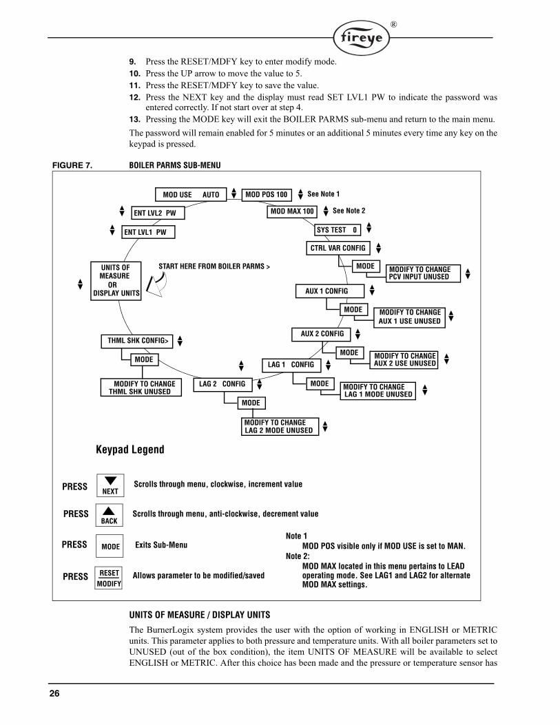
FIGURE 7. BOILER PARMS SUB-MENU
UNITS OF MEASURE / DISPLAY UNITS
The BurnerLogix system provides the user with the option of working in ENGLISH or METRICunits. This parameter applies to both pressure and temperature units. With all boiler parameters set toUNUSED (out of the box condition), the item UNITS OF MEASURE will be available to selectENGLISH or METRIC. After this choice has been made and the pressure or temperature sensor has
START HERE FROM BOILER PARMS >
Scrolls through menu, clockwise, increment value
Keypad Legend
CTRL VAR CONFIG
MODE MODIFY TO CHANGEPCV INPUT UNUSED
AUX 1 CONFIG
MODE MODIFY TO CHANGE
AUX 2 CONFIG
MODE MODIFY TO CHANGEAUX 2 USE UNUSED
NEXT
Scrolls through menu, anti-clockwise, decrement valueBACK
MODE
MODIFY
RESET
Exits Sub-Menu
Allows parameter to be modified/saved
AUX 1 USE UNUSED
UNITS OFMEASURE
DISPLAY UNITS
ENT LVL2 PW
LAG 1 CONFIG
MODE MODIFY TO CHANGE LAG 1 MODE UNUSED
MOD USE AUTO
MOD MAX 100
SYS TEST 0ENT LVL1 PW
LAG 2 CONFIG
MODE
MODIFY TO CHANGE
THML SHK CONFIG>
MODE
MODIFY TO CHANGE
LAG 2 MODE UNUSED
THML SHK UNUSED
PRESS
PRESS
PRESS
PRESS
OR
Note 1
MOD POS visible only if MOD USE is set to MAN.
Note 2:
MOD MAX located in this menu pertains to LEAD operating mode. See LAG1 and LAG2 for alternateMOD MAX settings.
See Note 2
MOD POS 100 See Note 1

27
®
been selected, UNITS OF MEASURE will be replaced by DISPLAY UNITS. This item can beselected anytime as ENGLISH or METRIC but applies only to dynamic readings of pressures or sen-sor values. That is, all programmed parameters will be stored in units according to the previouslyselected UNIT OF MEASURE choice. The only method to change UNITS OF MEASURE is toreset all parameters back to the out of the box condition, erasing all currently programmed settings.This is done through the SYSTEM TEST key.
SYSTEM TEST
The BurnerLogix contains some useful functions that are only accessible through the SYSTEMTEST parameter.
CONTROL VARIABLE CONFIGURATION SUB-MENU
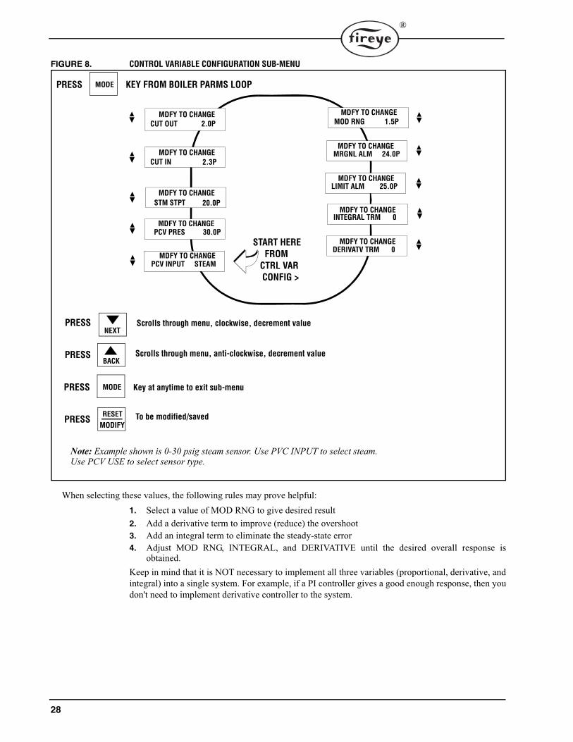
The CTRL VAR CONFIG> sub-menu allows the user to select and setup the Primary Control Vari-able, pressure or temperature. All parameters in this sub-menu are password protected. The values ofother sub-menus, such as LAG 1 and THERMAL SHOCK, are dependent on the selections made inthis sub-menu. The STPT value is the target value the BurnerLogix will attempt to maintain. CUT INis a differential value that is subtracted from the STPT and determines the point where a burner cyclebegins. CUT OUT is a differential value that is added to the STPT and determines the point where aburner cycle ends. MOD RNG is a differential value and is subtracted from the STPT and determinesthe proportional band or response curve (slope) of the firing rate motor. A small value of MOD RNGwill make the burner more responsive to process load changes. Care should be taken in selecting theproper value of MOD RNG as a system too responsive could cause overshoot and therefore shortcycling of the burner. Both INTEGRAL and DERIVATIVE terms are used to eliminate steady-stateerror and reduce overshoot. They each have a range of 0 to 100%. This value determines how muchof the error to factor in the calculation. A value of 0 turns the function off.
SYSTEM TEST PARAMETER
DESCRIPTION
0 No action, has no function. Allows user to exit MDFY mode with no action being taken.
2 Immediately disables the enabled passwords. Both Level 1 and Level 2 passwords will need to be re-entered to modify protected variables. Has no effect if both passwords are set to 0 (i.e. no password is enabled).
245 Reset all System Variables back to system factory default values.
28
®
FIGURE 8. CONTROL VARIABLE CONFIGURATION SUB-MENU
When selecting these values, the following rules may prove helpful:1. Select a value of MOD RNG to give desired result 2. Add a derivative term to improve (reduce) the overshoot 3. Add an integral term to eliminate the steady-state error 4. Adjust MOD RNG, INTEGRAL, and DERIVATIVE until the desired overall response is
obtained. Keep in mind that it is NOT necessary to implement all three variables (proportional, derivative, andintegral) into a single system. For example, if a PI controller gives a good enough response, then youdon't need to implement derivative controller to the system.
PCV PRES 30.0P
PCV INPUT STEAM
START HERE
MODE
MDFY TO CHANGE
CUT OUT 2.0P
MDFY TO CHANGE
CUT IN 2.3P
DERIVATV TRM 0
INTEGRAL TRM 0
LIMIT ALM 25.0P
MRGNL ALM 24.0P
MOD RNG 1.5P
FROM
CTRL VAR
CONFIG >
PRESS KEY FROM BOILER PARMS LOOP
MODEPRESS Key at anytime to exit sub-menu
Scrolls through menu, clockwise, decrement valueNEXT
Scrolls through menu, anti-clockwise, decrement valueBACK
PRESS
PRESS
MODIFY
RESET To be modified/savedPRESS
MDFY TO CHANGE
STM STPT 20.0P
MDFY TO CHANGE
MDFY TO CHANGE
MDFY TO CHANGE
MDFY TO CHANGE
MDFY TO CHANGE
MDFY TO CHANGE
MDFY TO CHANGE
Note: Example shown is 0-30 psig steam sensor. Use PVC INPUT to select steam. Use PCV USE to select sensor type.

29
®
SEQUENCE OF OPERATION - OPERATING CONTROL
Note: Refer to Figure 9.The BurnerLogix performs the operating control function to cycle the boiler on and off to maintainthe programmed pressure or temperature setpoint. The BurnerLogix will command the burner on andoff according to the following setpoints located in the CONTROL VAR CONFIG sub-menu:STM STPT 1(Steam Pressure Setpoint) - This determines the steam pressure the BurnerLogix willmaintain the boiler.
orWTR STPT 1 (Water Temperature Setpoint) - This determines the water temperature the Burner-Logix will maintain the boiler.CUT IN (Cut In Value) - Determines the point in which the steam pressure (or water temperature)must reach to start a burner cycle. This is a differential value that is subtracted from the steam pres-sure setpoint (STM STPT) or water temperature setpoint (WTR STPT).CUT OUT (Cut Out Value) - Determines the point in which the steam pressure (or water tempera-ture) must reach to end a burner cycle and initiate a normal shutdown. This is a differential value thatis added to the steam pressure setpoint (STM STPT) or water temperature setpoint (WTR STPT).Refer to Figure 8. When the steam pressure (or water temperature) is above the cut out point (Point“E”), system demand is satisfied and the BurnerLogix will be in Standby mode. As system demandincreases and the steam pressure (or water temperature) falls below the cut in point (Point “D” - seenote below), the BurnerLogix will initiate a burner cycle.Note: The cut in setpoint (CUT IN) is a differential value. Point “D” (steam pressure or water tem-perature in which the operating control closes) is determined by subtracting the cut in setpoint(CUT IN) from the steam pressure setpoint (STM STPT) or water temperature setpoint (WTRSTPT).In Figure 8, the Cut In setpoint (CUT IN) is programmed to zero, so the cut in point for the operat-ing control (Point “D”) is the same as the Steam Pressure Setpoint (STM STPT).Burner cut in, cutout and setpoint are matter of preference and expected boiler performance.When all other circuits within the Operating Control circuit, L1-3, of the BurnerLogix are closed, aburner start-up sequence will be initiated. See Figure 18 for suggested wiring diagram. A burner set-up sequence consists of Pre-Purge, Pilot Trial For Ignition, and Main Trial For Ignition (MTFI).Upon completion of the MTFI, the BurnerLogix moves to AUTO and the firing rate motor is con-trolled according to the user programmed setpoint parameters. (see SEQUENCE OF OPERATION -MODULATING CONTROL section).Whenever the steam pressure (or water temperature) rises above the cut out point (Point “E” – seenote below), the BurnerLogix will initiate a normal shutdown sequence (e.g.: de-energize main fuelvalve, drive the firing rate motor to low fire) and proceed through post purge and back to Standby.Note: The cut out setpoint (CUT OUT) is a differential value. Point “E” (steam pressure or watertemperature in which the operating control opens) is determined by adding the cut out setpoint(CUT OUT) to the steam pressure setpoint (STM STPT) or water temperature setpoint (WTRSTPT).
30
®
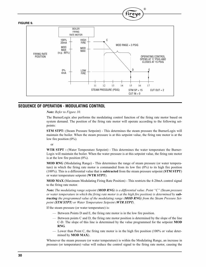
FIGURE 9.
SEQUENCE OF OPERATION - MODULATING CONTROL
Note: Refer to Figure 10.The BurnerLogix also performs the modulating control function of the firing rate motor based onsystem demand. The position of the firing rate motor will operate according to the following set-points:STM STPT1 (Steam Pressure Setpoint) - This determines the steam pressure the BurnerLogix willmaintain the boiler. When the steam pressure is at this setpoint value, the firing rate motor is at thelow fire position (0%).
orWTR STPT 1 (Water Temperature Setpoint) - This determines the water temperature the Burner-Logix will maintain the boiler. When the water pressure is at this setpoint value, the firing rate motoris at the low fire position (0%).MOD RNG (Modulating Range) - This determines the range of steam pressure (or water tempera-ture) in which the firing rate motor is commanded from its low fire (0%) to its high fire position(100%). This is a differential value that is subtracted from the steam pressure setpoint (STM STPT)or water temperature setpoint (WTR STPT).MOD MAX (Maximum Modulating Firing Rate Position) - This restricts the 4-20mA control signalto the firing rate motor.Note: The modulating range setpoint (MOD RNG) is a differential value. Point “C” (Steam pressureor water temperature in which the firing rate motor is at the high fire position) is determined by sub-tracting the programmed value of the modulating range (MOD RNG) from the Steam Pressure Set-point (STM STPT) or Water Temperature Setpoint (WTR STPT).If the steam pressure (or water temperature) is:
— Between Points D and E, the firing rate motor is in the low fire position.— Between points C and D, the firing rate motor position is determined by the slope of the line
C-D. The slope of this line is determined by the value programmed for the setpoint MODRNG.
— Lower than Point C, the firing rate motor is in the high fire position (100% or value deter-mined by MOD MAX).
Whenever the steam pressure (or water temperature) is within the Modulating Range, an increase inpressure (or temperature) value will reduce the control signal to the firing rate motor, causing the
LOWFIRE
D E
STEAM PRESSURE (PSIG)
11 12 13 14 15 16 17
MODMAX
CHIGHFIRE
100%20mA
MODMAX
(e.g.: 80%)
0%4mA
MOD RNGE = 3 PSIG
STM SP = 15 CUT OUT = 2CUT IN = 0
OPERATING CONTROLOPENS AT 17 PSIG AND
CLOSES AT 15 PSIG
FIRING RATEPOSITION
BOILERFIRING
RATE MOTOR

31
®
motor (or valve actuator) to drive towards its closed or low fire position. Similarly, a decrease in thesteam pressure (or water temperature) will increase the control output signal, causing the valves anddampers to move toward their open or high fire position.The value of the modulating range (MOD RNG) determines how the BurnerLogix responds tochanges in the measured variable (steam pressure or water temperature). A small modulating rangewill cause the control to respond quickly to small changes in steam pressure or water temperature. Asmall value of MOD RNG might result in the firing rate motor to cycle excessively and possiblycause the burner to actually short cycle. A large value would reduce the cycling of the firing ratemotor, but may cause the system to be somewhat sluggish in response to a change in steam pressureor water temperature. Matching the capacity of the boiler to load system demand are important con-siderations in setting the MOD RNG setpoint. Care should be taken when selecting this variable.The BurnerLogix control also provides PID control (Proportional + Integral+ Derivative) to improvesystem response to varying load changes. Refer to “Proportional plus Integral plus Derivative con-trol.Maximum Modulating Firing Rate Position (MOD MAX)The Maximum Modulating Firing Rate Position is a programmable setpoint which will clamp the 4-20mA control signal to the Firing Rate Motor. This setpoint will also affect the cycling rate of theboiler. This setpoint is programmed as a percentage, from 0% to 100%.Manual Positioning of the Firing Rate Motor (MOD USE)Although normal operation of the BurnerLogix system is to automatically control the modulatingmotor based on programmed set points, MOD USE provides the user the option of manually posi-tioning the modulating motor. Manual control of the modulating motor is normally used in lieu ofthe standard manual / auto potentiometer found on older burner cabinets. At times it may be desir-able to either limit the firing rate or base load one boiler in a multiple boiler environment.The MOD USE setpoint has two selections: AUTO and MANUAL. The AUTO selection will havethe BurnerLogix modulate the firing rate motor based on system demand. The MANUAL selectionwill allow the user to manually command the firing rate position. The current MOD USE state isdisplayed on the ALL-INFO screen.
Modulate Motor Position (MOD POS)Use this setpoint to manually position the modulator (firing rate) motor. The motor will move aslong while the NEXT or BACK key are depressed. Use the RESET/MDFY key to save the position.MOD USE, MOD POS and MOD MAX setpoints are all located in the BOILER PARMS sub-menu. MOD POS is displayed only if MOD USE is set to MAN.To manually position the firing rate motor:1. While in STANDBY and with burner off, and from the ALL-INFO screen, pressing the MODE
key will move to the top of the BurnerLogix Main menu where L1-3 OPEN or L1-3 CLOSED isdisplayed. Pressing MODE again will move the display to either MOD USE if in AUTO modeor to MOD POS if in MAN mode. If changing to MAN mode, press the RESET/MDFY key andthe NEXT or BACK key to change to MAN and then the RESET/MDFY key to save thechange. Press the NEXT key to move to MOD POS and then the RESET/MDFY key to manu-ally position the firing rate motor. When complete, press the RESET/MDFY key to save theposition. Pressing the MODE key will move the display to the top of the BurnerLogix Mainmenu screen and then to the ALL-INFO screen.
2. While in AUTO or main firing period, and from the ALL-INFO screen, pressing the MODE keywill move directly to either the MOD USE if in AUTO mode or to MOD POS if in MAN mode.If changing to AUTO mode and at MOD POS screen, use the BACK key to move to MOD USE
CAUTION: As long as the setpoint MOD USE is programmed MANUAL, the BurnerLogixWILL NOT control the firing rate motor based on system demand, but will remain in man-ual control indefinitely.

32
®
and make change to AUTO. If currently in MAN mod and at MOD POS screen, press theRESET/MDFY key and either the NEXT or BACK key to manually change the current firingrate position. The firing rate motor will move while the NEXT or BACK keys are depressed.When complete, press the RESET/MDFY key to save the position. Pressing the MODE key willmove the display to the top of the BurnerLogix Main menu screen and then to the ALL-INFOscreen.
The BurnerLogix system has bumpless transfer. If the burner is at the AUTO position and the currentmodulating mode is changed from AUTOMATIC (AUTO) to MANUAL (MAN) mode, MODPOS will assume the value of the current firing rate position. The operator can change the position toany value through the MOD POS option that follows the MOD USE option in the menu. On the sub-sequent burner cycle, the firing motor will move to the saved MOD POS value when it gets toAUTO.
SEQUENCE OF OPERATION - MARGINAL AND HIGH ALARM LIMITS
The PCV, AUX1 and AUX2 sensors installed with the BurnerLogix provide both high marginalalarm and high limit alarm functions. The marginal limit can be used to provide an indication that thesensor value is approaching the high alarm limit before the alarm limit is actually reached. For exam-ple, a Marginal Stack Alarm may be an indication of the burner overfiring, fouled heat exchanger,tube leak in heat exchanger, etc.
The user can program both high marginal and high limit alarm setpoints for the temperature or pres-sure sensors based on the input signal received. If the temperature or pressure exceeds the marginalhigh limit for 4 seconds, the alarm output relay will be activated, and the system will remain on line.If the temperature or pressure high limit alarm is exceeded the BurnerLogix will proceed to lockoutrequiring manual reset.The marginal high setpoint cannot be set higher than the high limit alarm setpoint nor can either beset lower than the sum of setpoint (STPT) plus cut out (CUT OUT). Alarm points for stack monitor-ing can be set anywhere within the sensor range to meet the application. The marginal high limit andhigh limit alarm setpoints are shown on the display as MRGNL ALM and LIMIT ALM respectively.
SEQUENCE OF OPERATION - COLD START THERMAL SHOCK PROTECTION
Cold Start Thermal Shock Protection is designed to slowly increase the burner firing rate on a coldstart to limit mechanical stress due to thermal differences. The BurnerLogix offers two methods ofthermal shock protection: Low Fire and Segment. Thermal shock parameters are found in theBOILER PARMS menu in the THERMAL SHK CONFIG sub-menu. The setpoints associated withselecting this function are:• THML SHK (Thermal Shock Protection): This setpoint enables the thermal shock protection
function. The selections are UNUSED, LOW FIRE and SEGMENT.
IMPORTANT: In the event the Primary Control Variable (PCV) pressure or temperaturetransducer fails in such a manner as to output less than 4 mA or becomes disconnected, theBurnerLogix Z system will immediately shutdown and proceed to lockout with the messagePCV UNDER RANGE displayed. However, as boiler output is critical, and a replacementtransducer may not be immediately available, the user may continue to operate the boiler ifMOD USE is placed in the MANUAL position and the control is reset from lockout. The fir-ing rate position can now ONLY be manually controlled until a replacement transducer islocated and installed. The user must be cautioned the BurnerLogix Z system has no way ofknowing the operating pressure of temperature and it is up to the user to limit the output ofthe boiler.
WARNING: The electro-mechanical steam pressure or water temperature high limit switchMUST remain in the running interlock circuit (3-P).WARNING: Programming a sensor range that is different from the actual range of theinstalled sensor could result in improper operation.

33
®
• LOW FIRE METHOD: This method of cold start thermal shock protection is generally usedon Water Tube Boilers. The setpoints associated with this method of thermal shock protectionis:
• THML EXIT (Thermal Shock Exit Setpoint): The BurnerLogix will hold the FiringRate motor in the low fire (LF) position until the steam pressure (or water temperature)reaches the Thermal Shock Exit Setpoint (THML EXIT). Once this steam pressure (orwater temperature) is reached, the firing rate motor is positioned according to the mod-ulating control algorithm. See Figure 6.
• THML LF% (Low fire minimum): Use this selection to set the firing rate motor posi-tion during the low fire method operation.
Note: If AUX1 is programmed for STNDBY WTR, Thermal Shock Protection - Low Fire Methodwill control according to boiler water temperature and not steam pressure. See SEQUENCE OFOPERATION - STANDBY WATER section.
FIGURE 10. Cold Start Thermal Shock Protection - Low Fire Method
• SEGMENT METHOD: This method of cold start thermal shock protection is generally usedwith Fire Tube Boilers. The setpoints associated with this method of thermal shock protectionare:
• THML STRT (Thermal Shock Start Point): Determines the start point for thermalshock protection.
• THML EXIT (Thermal Shock Exit Point): Determines the exit point for thermalshock protection.
• THML OVRD (Timed Override Per Segment Setpoint): Determines maximum timeBurnerLogix holds the firing rate for each segment before increasing to the next seg-ment.
THML STRT and THML EXIT: Once the burner cycle starts, the BurnerLogix will hold the firingrate motor in the low fire position until the steam pressure (or water temperature) reaches the Ther-mal Shock Start Point (THML STRT). The BurnerLogix then automatically divides the differencebetween the high fire position and low fire position into sixteen (16) segments. The BurnerLogixalso divides the difference between the Thermal Shock Exit Point (THML EXIT) and ThermalShock Start Point (THML STRT) into sixteen (16) segments. The BurnerLogix will increase the fir-ing rate motor by the value of one segment, and wait until the steam pressure (or water temperature)increases by the amount of one segment. Once the steam pressure (or water temperature) increasesby the calculated amount, the BurnerLogix increases the firing rate motor by the value of one seg-ment and repeats the process. The BurnerLogix steps the firing rate motor until the steam pressure(or water temperature) reaches the Thermal Shock Exit Point (THML EXIT). At that point, the fir-ing rate motor is at the high fire position, and will remain at the high fire position until the steam
LOWFIRE
STM SP = 100 PSICUT IN = 0
CUT OUT = 20MOD RNGE = 30
10 20 30 40
HIGHFIRE
100%20mA
0%4mA
50 60 70 80 90 100 110 120 130THML EXIT = 40 PSI STEAM PRESSURE (PSIG)
BOILERFIRING
RATE MOTOR
THML EXIT

34
®
pressure (or water temperature) reaches the modulating range (MOD RNG). See SEQUENCE OFOPERATING - MODULATING CONTROL section.Note: If AUX1 is programmed for STNDBY WTR, Thermal Shock Protection - Segment Method willcontrol according to boiler water temperature and not steam pressure. See SEQUENCE OF OPERA-TION - STANDBY WATER section.THML OVRD: The Timed Override Per Segment Setpoint (THML OVRD) allows the user to pro-gram a maximum time period in which the control will try to increase the steam pressure (or watertemperature) at a specific firing rate position. If the steam pressure (or water temperature) DOESNOT increase to the appropriate value, the BurnerLogix will automatically advance the firing rateposition to the next position.
FIGURE 11. Cold Start Thermal Shock Protection - Segment Method
SEQUENCE OF OPERATION - LEAD/LAG CONTROL
In installations having multiple boilers, the BurnerLogix of each boiler can be set up to operate in aLead/Lag mode of operation. The BurnerLogix control provides two lead/lag setpoints, LAG1 andLAG2, each made active by separate 120 VAC digital inputs located on terminals 16 and 21. Pleasenote these inputs have multiple uses and must be programmed as LAG to utilize this function. Thefunction of Lead or Lag operation is determined by the status of a maintained 120 VAC wired to Ter-minals 16 and 21. The logic table for Lead and Lag operation is as follows:
With both inputs open, the BurnerLogix will operate in the LEAD mode. The current operatingmode, (LEAD, LAG1 or LAG2), is displayed on the ALL-INFO screen. LAG1 and LAG2 setpointsare found in the BOILER PARMS> menu under LAG1 CONFIG> and LAG2 CONFIG> respec-tively. Assuming LAG1 operation is selected, the BurnerLogix will control according to the follow-ing setpoints:LAG1 STPT (Lag Setpoint for Water Temperature or Steam Pressure): This is the system setpointthe BurnerLogix will maintain when it is selected for Lag Operation.CUT IN (Cut In): This is the setpoint where the BurnerLogix will close its operating control whenoperating as the Lag1 Boiler. This is a differential value that is subtracted from the Lag1 Setpoint
LAG 1 (16) LAG 2 (21) OPERATING MODE0 0 LEAD
120 Vac 0 LAG 1Don’t care 120Vac LAG 2
LOWFIRE
STM SP = 100 PSICUT IN = 0
CUT OUT = 20MOD RNGE = 30
10 20 30 40
HIGHFIRE
100%20mA
0%4mA
50 60 70 80 90 100 110 120 130
THML OVRD = 30 MIN STEAM PRESSURE (PSIG)
BOILERFIRING
RATE MOTOR
THML STRT = 20 PSI
THML EXIT = 60 PSI

35
®
(LAG1 STPT). When this value is set to zero, the Lag Boiler will close its operating control contactsat the programmed Lag Setpoint (LAG1 STPT).CUT OUT (Cut Out): This is the Cut Out value the BurnerLogix will use during Lag1 Operation.This is a differential value that is added to the Lag Setpoint LAG STPT). See SEQUENCE OFOPERATION - OPERATING CONTROL section.MOD RNG (Modulating Range): This is the Modulating Range the BurnerLogix will use duringLag1 Operation. This is a differential value that is subtracted from the Lag1 Setpoint (LAG1STPT). See SEQUENCE OF OPERATION - MODULATING CONTROL section.STRT DLY (Lag To Start Delay): A time delay (0 to 15 minutes) from when the control variablefalls below the cut in value to when the burner is commanded to initiate a burner start cycle. Theobject of this function is to allow the LEAD boiler time to recover from a change in load demand.During this delay period, the display screen will indicate the starting delay time and count down to 0as follows:
LAG DLY (Lead to Lag Delay): When a BurnerLogix control is commanded to go from LEADOperation to LAG Operation (based on the status of terminal 16 or 21), LEAD operation will con-tinue for this user settable delay (0 to 15 minutes) before switching to LAG operation. The purposefor this delay is it allow sufficient time for the “New Lead” Boiler to prepare to meet demand. Dur-ing this period the ALL-INFO display will indicate –
MOD MAX (Modulator Motor Maximum): Both LAG 1 and LAG 2 allow the modulating motortravel to be separately limited to a value of 0 to 100%. This can be useful where the maximum firingrate for an alternate fuel needs to be limited. Another use may be limited firing during an off peak orlow fire use period, i.e. weekends, holidays, etc.LAG CUT IN: The cut in setpoint (CUT IN) provides the two options for programming how theLag Boiler will respond to a call in demand. Programming the cut in setpoint to zero will close theoperating control at the Programmed Lag Setpoint for Steam Pressure or Hot Water (LAG1 STPT).This would cause the lead and lag boilers to operate as shown in Figure 9. By programming a valuegreater than zero for this setpoint, the user can program the Lag Setpoint for Steam Pressure or HotWater (LAG SP) the same as the Steam Pressure Setpoint (STM STPT) or Water Temperature Set-point (WTR STPT) as the Lead Boiler. This would cause the lead and lag boilers to operate asshown in Figure 12 and Figure 13.)
STANDBY 1:34LAG1 DELAYED
8.4P AUTO 52%LEAD>LAG1 FLM42
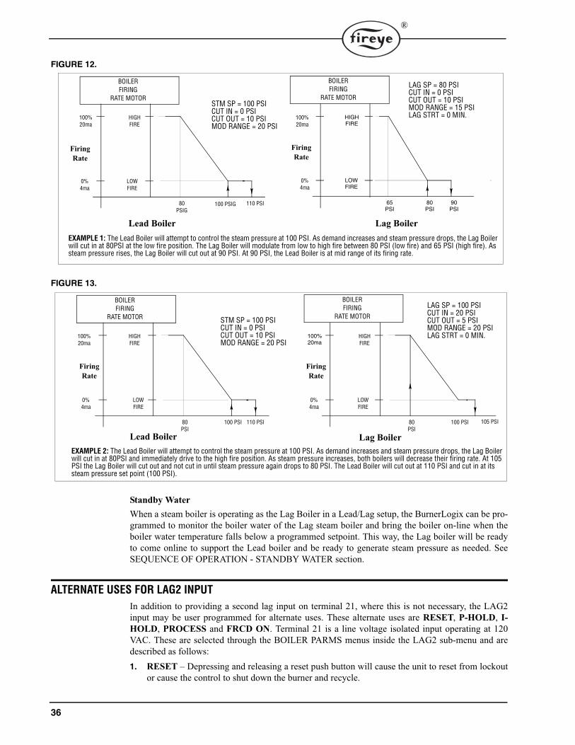
36
®
FIGURE 12.
FIGURE 13.
Standby WaterWhen a steam boiler is operating as the Lag Boiler in a Lead/Lag setup, the BurnerLogix can be pro-grammed to monitor the boiler water of the Lag steam boiler and bring the boiler on-line when theboiler water temperature falls below a programmed setpoint. This way, the Lag boiler will be readyto come online to support the Lead boiler and be ready to generate steam pressure as needed. SeeSEQUENCE OF OPERATION - STANDBY WATER section.
ALTERNATE USES FOR LAG2 INPUT
In addition to providing a second lag input on terminal 21, where this is not necessary, the LAG2input may be user programmed for alternate uses. These alternate uses are RESET, P-HOLD, I-HOLD, PROCESS and FRCD ON. Terminal 21 is a line voltage isolated input operating at 120VAC. These are selected through the BOILER PARMS menus inside the LAG2 sub-menu and aredescribed as follows:1. RESET – Depressing and releasing a reset push button will cause the unit to reset from lockout
or cause the control to shut down the burner and recycle.
80PSIG
100 PSIG 110 PSI 80PSI
90PSI
Lag BoilerLead BoilerEXAMPLE 1: The Lead Boiler will attempt to control the steam pressure at 100 PSI. As demand increases and steam pressure drops, the Lag Boiler will cut in at 80PSI at the low fire position. The Lag Boiler will modulate from low to high fire between 80 PSI (low fire) and 65 PSI (high fire). As steam pressure rises, the Lag Boiler will cut out at 90 PSI. At 90 PSI, the Lead Boiler is at mid range of its firing rate.
100%20ma
0%4ma
LAG SP = 80 PSICUT IN = 0 PSICUT OUT = 10 PSIMOD RANGE = 15 PSILAG STRT = 0 MIN.
STM SP = 100 PSICUT IN = 0 PSICUT OUT = 10 PSIMOD RANGE = 20 PSI
FiringRate
65PSI
HIGHFIRE
LOWFIRE
100%20ma
0%4ma
FiringRate
HIGHFIRE
LOWFIRE
BOILERFIRING
RATE MOTOR
BOILERFIRING
RATE MOTOR
EXAMPLE 2: The Lead Boiler will attempt to control the steam pressure at 100 PSI. As demand increases and steam pressure drops, the Lag Boiler will cut in at 80PSI and immediately drive to the high fire position. As steam pressure increases, both boilers will decrease their firing rate. At 105 PSI the Lag Boiler will cut out and not cut in until steam pressure again drops to 80 PSI. The Lead Boiler will cut out at 110 PSI and cut in at its steam pressure set point (100 PSI).
80PSI
100 PSI 110 PSI
Lead Boiler
100%20ma
0%4ma
STM SP = 100 PSICUT IN = 0 PSICUT OUT = 10 PSIMOD RANGE = 20 PSI
FiringRate
HIGHFIRE
LOWFIRE
80PSI
100 PSI 105 PSI
Lag Boiler
100%20ma
0%4ma
FiringRate
HIGHFIRE
LOWFIRE
LAG SP = 100 PSICUT IN = 20 PSICUT OUT = 5 PSIMOD RANGE = 20 PSILAG STRT = 0 MIN.
BOILERFIRING
RATE MOTOR
BOILERFIRING
RATE MOTOR
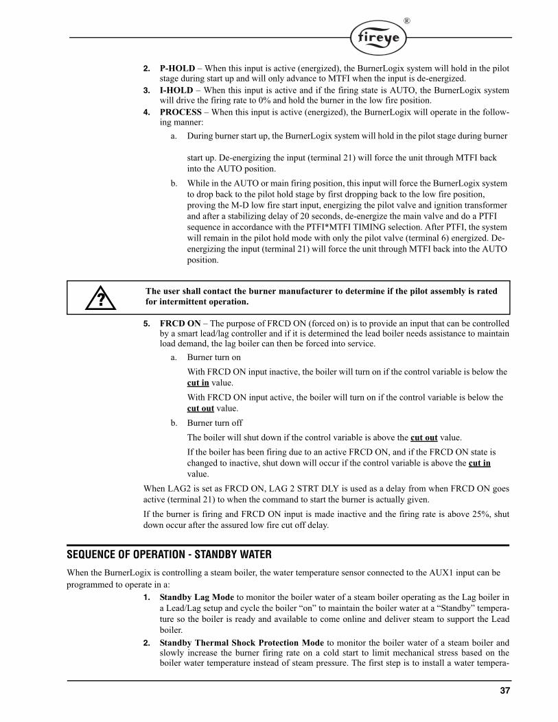
37
®
2. P-HOLD – When this input is active (energized), the BurnerLogix system will hold in the pilotstage during start up and will only advance to MTFI when the input is de-energized.
3. I-HOLD – When this input is active and if the firing state is AUTO, the BurnerLogix systemwill drive the firing rate to 0% and hold the burner in the low fire position.
4. PROCESS – When this input is active (energized), the BurnerLogix will operate in the follow-ing manner:
a. During burner start up, the BurnerLogix system will hold in the pilot stage during burner
start up. De-energizing the input (terminal 21) will force the unit through MTFI back into the AUTO position.
b. While in the AUTO or main firing position, this input will force the BurnerLogix system to drop back to the pilot hold stage by first dropping back to the low fire position, proving the M-D low fire start input, energizing the pilot valve and ignition transformer and after a stabilizing delay of 20 seconds, de-energize the main valve and do a PTFI sequence in accordance with the PTFI*MTFI TIMING selection. After PTFI, the system will remain in the pilot hold mode with only the pilot valve (terminal 6) energized. De-energizing the input (terminal 21) will force the unit through MTFI back into the AUTO position.
5. FRCD ON – The purpose of FRCD ON (forced on) is to provide an input that can be controlledby a smart lead/lag controller and if it is determined the lead boiler needs assistance to maintainload demand, the lag boiler can then be forced into service.
a. Burner turn onWith FRCD ON input inactive, the boiler will turn on if the control variable is below the cut in value.With FRCD ON input active, the boiler will turn on if the control variable is below the cut out value.
b. Burner turn offThe boiler will shut down if the control variable is above the cut out value.If the boiler has been firing due to an active FRCD ON, and if the FRCD ON state is changed to inactive, shut down will occur if the control variable is above the cut invalue.
When LAG2 is set as FRCD ON, LAG 2 STRT DLY is used as a delay from when FRCD ON goesactive (terminal 21) to when the command to start the burner is actually given.If the burner is firing and FRCD ON input is made inactive and the firing rate is above 25%, shutdown occur after the assured low fire cut off delay.
SEQUENCE OF OPERATION - STANDBY WATER
When the BurnerLogix is controlling a steam boiler, the water temperature sensor connected to the AUX1 input can be programmed to operate in a:
1. Standby Lag Mode to monitor the boiler water of a steam boiler operating as the Lag boiler ina Lead/Lag setup and cycle the boiler “on” to maintain the boiler water at a “Standby” tempera-ture so the boiler is ready and available to come online and deliver steam to support the Leadboiler.
2. Standby Thermal Shock Protection Mode to monitor the boiler water of a steam boiler andslowly increase the burner firing rate on a cold start to limit mechanical stress based on theboiler water temperature instead of steam pressure. The first step is to install a water tempera-
The user shall contact the burner manufacturer to determine if the pilot assembly is ratedfor intermittent operation.?
38
®
ture sensor (P/N TS350-2, -4, or -8 or TS752-2, -4, or -8) on the steam boiler, connect it to theAUX1 input, and program the sensor to operate in the STNDBY WTR mode.
STANDBY LAG MODE
To program the BurnerLogix to control a steam boiler in the “Standby Lag Mode”, the user programsthe following setpoints which are found under AUX1 CONFIG>:STNDBY WTR: This selects the temperature sensor connected to the AUX1 input terminals will beused to monitor the boiler water of a steam boiler and programmed to operate in the STNDBY WTRmode. See GETTING STARTED - Select and Program the Pressure and Temperature Sensor Rangessection.STNDBY STPT (Water Temperature Setpoint): This determines the boiler water temperature theBurnerLogix will maintain.CUT IN (Cut In Value): Determines the point in which the boiler water temperature must reach toclose the operating control. This is a differential value that is subtracted from the water temperaturesetpoint (WTR SP).CUT OUT (Cut Out Value): Determines the point in which the boiler water temperature must reachto open the operating control. This is a differential value that is added to the water temperature set-point (WTR SP).MOD RNG (Modulating Range): This determines the range of boiler water temperature in which thefiring rate motor is commanded from its low fire to its high fire position.The Standby mode of operation is similar to the operating control and modulating control functions.See SEQUENCE OF OPERATION - OPERATING CONTROL and SEQUENCE OF OPERATION-MODULATING CONTROL sections.When AUX1 is configured to be used as standby water, both lead or lag pressure and temperatureinputs are monitored continuously with steam pressure having priority. Because both steam andwater are active inputs, the BurnerLogix will operate the burner in the following manner:1. While the standby water temperature is above its cut in point, the lead or lag steam pressure cut
in point is monitored.2. If the standby water temperature is above its cut in point and the lead or lag steam pressure is
below its cut in point, the burner will operate and control according to the steam pressure set-points.
3. If the standby water temperature is less than its cut in point and the lead or lag steam pressure isless than its cut in point then:
a. If thermal shock is active and the standby water temperature is less than the thermal shock exit point, the boiler will be controlled according to the thermal shock setpoints (temperature).b. If the standby water temperature is above the thermal exit point, the boiler will be controlled according to the lead or lag steam pressure setpoints.c. While the boiler is firing and the standby water setpoint is satisfied and if the steam pressure is below its setpoint then control is switched to the lead or lag steam pressure parameters.
WARNING: Location of the boiler water temperature sensor is critical in the operation ofStandby Water. Consult the boiler manufacturer for guidance for its location or refer toBulletin TS-3501 for proper location and wiring of this temperature sensor.CAUTION: Programming the AUX 1 USE for STANDBY WTR automatically converts allof the setpoints associated with the operation of Thermal Shock Protection to UNUSED. SeeSEQUENCE OF OPERATION- COLD START THERMAL SHOCK PROTECTION sec-tion to set these values properly.

39
®
4. If standby water temperature is less then its cut in value and the lead or lag steam pressure aboveits cut in value, then the boiler will operate according to the standby water parameters.
In Figure 14, whenever the boiler water temperature is above 190F (Cut out point), the OperatingControl Output of the BurnerLogix is open. When the boiler water temperature falls to 180F (Cut inpoint), the Operating Control Output closes and a burner start-up sequence will be initiated. TheBurnerLogix will modulate the firing rate damper motor based on boiler water temperature until thetemperature rises above 190F (Cut out point).
FIGURE 14.
STANDBY THERMAL SHOCK PROTECTION MODE:
To program the BurnerLogix to control a steam boiler in the “Standby Thermal Shock ProtectionMode” to perform thermal shock protection by monitoring the boiler water temperature instead ofsteam pressure, the user programs the following setpoints which are found under AUX1 SET-POINTS:AUX1 USE: The temperature sensor connected to the AUX1 input will be used to monitor the boilerwater of a steam boiler. Program this setpoint to STNDBY WTR. See GETTING STARTED -SELECT AND PROGRAM THE PRESSURE AND TEMPERATURE SENSOR RANGES section.After programming the AUX1 for STNDBY WTR selecting the appropriate temperature sensor,350F or 752F, the following setpoints also need to be programmed: STANDBY STPT, CUT IN,CUT OUT, and MOD RNG.Note: Once AUX1 CONFIG is programmed for STNDBY WTR, all THERMAL SHOCK setpointswill be set to temperature. If thermal shock is to be used, these setpoints must be properly pro-grammed by the installer or operator. Refer back to the section discussing Thermal shock operation.
LOWFIRE
BOILER WATER TEMP. OF STEAM BOILER
150� 160� 170� 200�
HIGHFIRE
100%20mA
0%4mA
180� 190�
FOR LAG MODE OPERATION:
AUX 1 USE = STANDBY WTRSTNDBY STPT = 180oF
CUT IN = 0oFCUT OUT = 10oF
MOD RNGE = 20oF
Setpoints for Lag Mode operation
BOILERFIRING
RATE MOTOR

40
®
FIGURE 15.
ALTERNATE USES FOR AUX 1 INPUT
AUX 1 input accepts any of the listed pressure or temperature sensors and can be utilized for a vari-ety of purposes.
MONITORING PRESSURE - PRESUsing any of the listed pressure transducers, the user can monitor and display any pressure notrelated to the boiler steam pressure. For example, on an oil fired boiler the user may want to install tomonitor burner oil pressure and have that information available to the display screen as well throughmodbus communications.
STANDBY WATER - STNDBY WTROnly AUX 1 can be used for STANDBY WATER. Refer to the previous sections explaining theoperation of STANDBY WATER.
MONITOR TEMPERATURE - MNITRUsing any of the listed pressure transducers, the user can monitor and display any temperature notrelated to the boiler water temperature. For example, on an oil fired boiler the user may want toinstall to monitor burner oil temperature or in a hot water system the return hot water. This informa-tion is to the display screen as well through modbus communication.
STACK TEMPERATURE - STACKA temperature sensor can be installed to monitor the stack temperature of the boiler. A high limitalarm and marginal high limit alarm can be programmed for that sensor. When the high limit alarm isexceeded, the BurnerLogix Z system will shutdown and lockout the boiler. The appropriate alarmmessage will be displayed. When AUX 1 is selected as Stack Temperature (STACK TEMP), the userhas the option of sensor range, 32-350F or 32-752F. The user then programs in the MARGINALHIGH LIMIT (MRGNL STACK) followed by the HIGH LIMIT (LIMIT STACK).
LOWFIRE
HIGHFIRE
100%20mA
0%4mA
100 F 140 F 180 F 220 F 70 PSI 80 PSI 90 PSI 100 PSI 110 PSI 120
THML SHK = USEDTHML MTHD = SEGMENTTHML START = 100oFTHML EXIT = 220oFTHML OVRD = 30 MIN.
BOILER WATER TEMP.
STM STPT = 100 PSICUT IN = 0 PSICUT OUT = 10 PSIMOD RNGE = 20 PSI
STEAM PRESSURE
Once boiler water temperature reaches 220�F, Burnerlogix controls firing rate motor based on steam pressure.
BOILERFIRING
RATE MOTOR

41
®
FIGURE 16. AUX 1 SUB MENU
PRESS MODE TO ENTER
UNUSED
PRES
NONE
1030m
15P 30P
2060m
200P 300P
13.8B 20.7B
MNITRTEMP
NONE
176C
350F 752F
400C
STACKTEMP
NONE
176C
350F 752F
400C
MRGNLSTACK
LIMITSTACK
PRESS MODE AT ANYTIME TO EXIT SUBMENU OR CANCEL CHOICE
AUX 1 CONFIG >
STNDBYWTR
NONE
176C
350F 752F
400C
STNDBY STPT
CUT IN
CUT OUT
MOD RNG

42
®
ALTERNATE USES FOR AUX 2 INPUT
AUX 2 input accepts any of the listed pressure or temperature sensors and can be utilized for a vari-ety of purposes.
MONITORING PRESSURE - PRESUsing any of the listed pressure transducers, the user can monitor and display any pressure notrelated to the boiler steam pressure. For example, on an oil fired boiler the user may want to install tomonitor burner oil pressure and have that information available to the display screen as well throughmodbus communication.
MONITOR TEMPERATURE - MNITRUsing any of the listed pressure transducers, the user can monitor and display any temperature notrelated to the boiler water temperature. For example, on an oil fired boiler the user may want toinstall to monitor burner oil temperature or in a hot water system the return hot water. This informa-tion is to the display screen as well through modbus communication.
MONITOR OUTDOOR TEMPERATURE - OUTDRA temperature sensor can be installed to monitor outdoor air temperature. An operating inhibit set-point (OUTDR STPT) can then be programmed so that when the outdoor air temperature is abovethis inhibit setpoint, the operating control circuit of the BurnerLogix Z system will not respond tosystem demand and initiate a burner cycle. While this condition exists the display will indicateOUTDR TEMP> STPT. The outdoor air temperature must fall three (3) degrees below the inhibit set-point before the operating control circuit will respond to system demand. When AUX 2 is selected asOutdoor Temperature (OUTDR TEMP), the user has the option of sensor range, 32-350F or 32-752F.The user then programs in the OUTDOOR SETPOINT (OUTDR STPT).
STACK TEMPERATURE - STACKA temperature sensor can be installed to monitor the stack temperature of the boiler. A high limitalarm and marginal high limit alarm can be programmed for that sensor. When the high limit alarm isexceeded, the BurnerLogix Z system will shutdown and lockout the boiler. The appropriate alarmmessage will be displayed. When AUX 2 is selected as Stack Temperature (STACK TEMP), the userhas the option of sensor range, 32-350F or 32-752F. The user then programs in the MARGINALHIGH LIMIT (MRGNL STACK) followed by the HIGH LIMIT (LIMIT STACK).

43
®
FIGURE 17. AUX 2 SUB MENU
PRESS MODE TO ENTER
UNUSED
PRES
NONE
1030m
15P 30P
2060m
200P 300P
13.8B 20.7B
MNITRTEMP
NONE
176C
350F 752F
400C
OUTDRTEMP
NONE
176C
350F 752F
400C
STACKTEMP
NONE
176C
350F 752F
400C
OUTDR STPT
MRGNL STACK
LIMIT STACK
PRESS MODE AT ANYTIME TO EXIT SUBMENU OR CANCEL CHOICE
AUX 2 CONFIG >

44
®
FLAME SCANNERS
INSTALLATION - UV SCANNERS
Where possible, obtain the burner manufacturer’s instructions for mounting the scanner. This infor-mation is available for most standard burners. The scanner mounting should comply with the follow-ing general instructions:1. Position the UV1A, UV2 scanner within 30 inches of the flame to be monitored; the 45UV5
within 72 inches, closer if possible.2. Select a scanner location that will remain within the ambient temperature limits of the UV Scan-
ner. If cooling is required, use an insulating coupling (Fireye #35-69 for UV1A, UV2 Scanners,#35-127-1 for 45UV5) to reduce conducted heat.
3. The UVlA, UV2, 45UV5 Scanners are designed to seal off the sight pipe up to 1 PSI pressure.Higher furnace pressures should be sealed off. To seal off positive furnace pressure up to 100PSI for UV1A, UV2 Scanners, install a quartz window coupling (#60-1257) For 45UV5 Scan-ners, use #60-1100 coupling. Add cooling air to reduce the scanner sight pipe temperature.
4. Install the scanner on a standard NPT pipe (UV1A: 1/2", UV2: 3/8", 45UV5: 1") whose positionis rigidly fixed. If the scanner mounting pipe sights through the refractory, do not extend it morethan halfway through. Swivel flanges are available if desired (#60-302 for UV1A, UV2 Scan-ners, #60-1664-3 for 45UV5). The sight pipe must permit an unobstructed view of the pilot and/or main flame, and both pilot and main flames must completely cover the scanner field of view
.
5. Smoke or unburned combustion gases absorb ultraviolet energy. On installations with negativepressure combustion chambers, a small hole drilled in the UV1A, UV2 sight pipe will assist in
CAUTION: The UV1A, UV2, UV8A, UV90 and 45UV3 flame scanners and associatedamplifier module are non-self checking UV systems and should be applied only to burnersthat cycle often (e.g.: a minimum of once per 12 hours) in order for the safety checking cir-cuit to be exercised. If component checking is required during burner operation for con-stantly fired burners, utilize the self-checking ultra-violet flame scanners (45UV5, 55UV5)with associated amplifier module (ZB110UVSC), or the infrared flame scanner (48PT2)with associated Auto Check amplifier (ZB110IR activated).
SCANNER MUST HAVE UNOBSTRUCTEDVIEW OF FLAME
NOT THIS NOT THIS BUT THIS
FLAME MUST COMPLETELY COVERSIGHT OPENING
NOT THIS NOT THIS BUT THIS

45
®
keeping the pipe clean and free from smoke. For positive pressure furnaces, provide clean air topressurize the sight pipe, if necessary.
6. Two UV1A or UV2 Scanners may be installed on the burner if it is necessary to view two areasto obtain reliable detection of the flame. They should be wired in parallel. Only one repetitiveselfchecking 45UV5 Scanner may be installed on a burner.
7. To increase scanner sensitivity with UV1A, UV2 Scanners, a quartz lens permits location of thescanner at twice the normal distance. Use l/2" x 1 l/2" pipe nipple between UV1A Scanner andthe coupling. Use 3/8" pipe nipple and a l/2" x 3/8" bushing on UV2 installations.
8. Request the assistance of any Fireye field office for recommendations of a proper scanner instal-lation on a non-standard application.
FIGURE 18. TYPICAL SCANNER INSTALLATIONS
OPERATION — 45UV5 & 55UV5 SELF-CHECKING UV SCANNER
Self-checking ultraviolet scanners should be used in applications where burner firing operation iscontinuous or where the burner is on for long periods of time without recycling. In addition, ultravi-olet self-checking systems are mandatory in some locations.The operation of this type of system consists of maintaining the flame scanning capability at alltimes while also proving that the ultraviolet tube is firing properly. This is done periodically bymechanically closing off the sight of the UV tube and checking to make sure that the flame signalgoes away.A shutter assembly in the 45UV5 scanner performs this function. Figure 19 explains the process fur-ther.If the shutter assembly in the scanner fails, the tube is faulty, or there is insufficient power to thescanner, the BurnerLogix will LOCKOUT and display the following message LOCKOUT CHECKSCANNER. The ultraviolet tube is replaceable (P/N 4-314-1).A lockout will result if a minimum signal is detected for three consecutive shutter closed periods.
The maximum UV signal from a flame is found in the first one-third of the visible flame taken from the point where the flame begins. The scanner sight pipe should be aimed at this area.
DO NOT EXTENDMORE THANHALF-WAY INTOREFRACTORY
SCANNER
FORCEDCLEAN AIR(FROM DISCHARGEOF FAN)
METHODS OF COOLING SCANNER
INSULATINGTUBING
SEALINGUNION FORCED
AIR
EXTEND SIGHTING TUBE6”(152.4) OR 8”(203.2)
DO NOT EXTEND MORE THANHALF-WAY INTO REFRACTORY
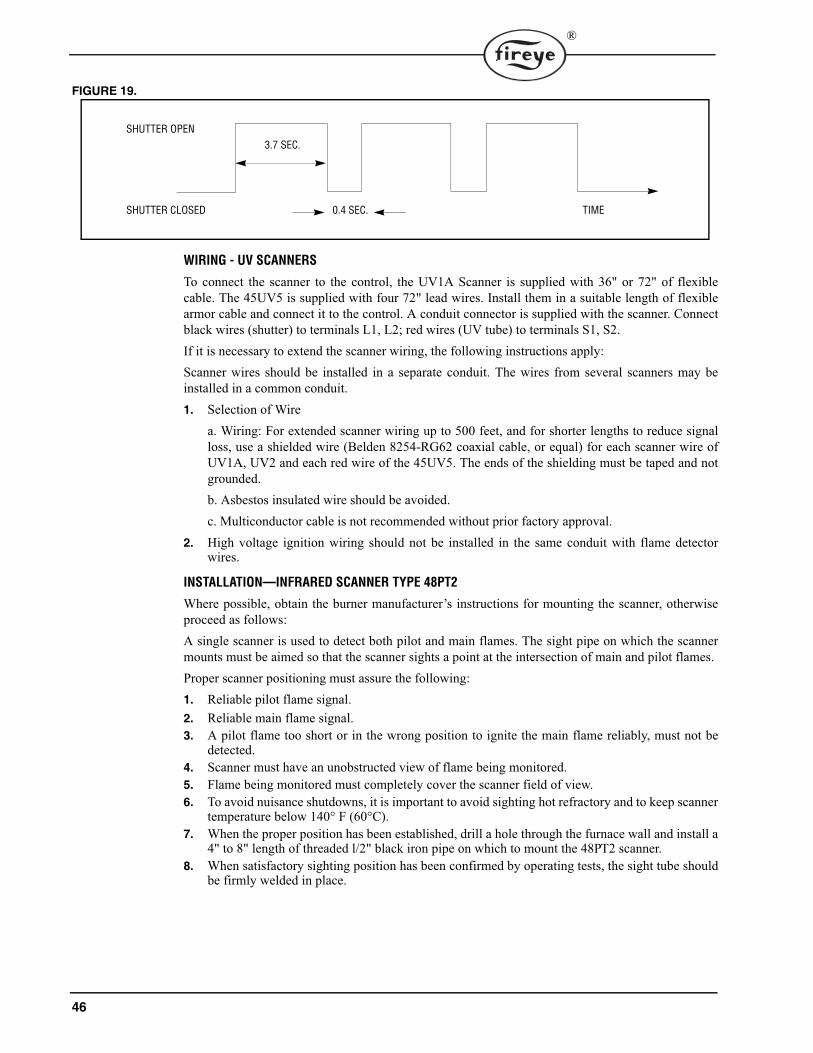
46
®
FIGURE 19.
WIRING - UV SCANNERS
To connect the scanner to the control, the UV1A Scanner is supplied with 36" or 72" of flexiblecable. The 45UV5 is supplied with four 72" lead wires. Install them in a suitable length of flexiblearmor cable and connect it to the control. A conduit connector is supplied with the scanner. Connectblack wires (shutter) to terminals L1, L2; red wires (UV tube) to terminals S1, S2.If it is necessary to extend the scanner wiring, the following instructions apply:Scanner wires should be installed in a separate conduit. The wires from several scanners may beinstalled in a common conduit.1. Selection of Wire
a. Wiring: For extended scanner wiring up to 500 feet, and for shorter lengths to reduce signalloss, use a shielded wire (Belden 8254-RG62 coaxial cable, or equal) for each scanner wire ofUV1A, UV2 and each red wire of the 45UV5. The ends of the shielding must be taped and notgrounded.b. Asbestos insulated wire should be avoided. c. Multiconductor cable is not recommended without prior factory approval.
2. High voltage ignition wiring should not be installed in the same conduit with flame detectorwires.
INSTALLATION—INFRARED SCANNER TYPE 48PT2
Where possible, obtain the burner manufacturer’s instructions for mounting the scanner, otherwiseproceed as follows:A single scanner is used to detect both pilot and main flames. The sight pipe on which the scannermounts must be aimed so that the scanner sights a point at the intersection of main and pilot flames.Proper scanner positioning must assure the following:1. Reliable pilot flame signal.2. Reliable main flame signal.3. A pilot flame too short or in the wrong position to ignite the main flame reliably, must not be
detected.4. Scanner must have an unobstructed view of flame being monitored.5. Flame being monitored must completely cover the scanner field of view.6. To avoid nuisance shutdowns, it is important to avoid sighting hot refractory and to keep scanner
temperature below 140° F (60°C). 7. When the proper position has been established, drill a hole through the furnace wall and install a
4" to 8" length of threaded l/2" black iron pipe on which to mount the 48PT2 scanner. 8. When satisfactory sighting position has been confirmed by operating tests, the sight tube should
be firmly welded in place.
SHUTTER OPEN
SHUTTER CLOSED
3.7 SEC.
0.4 SEC. TIME

47
®
FIGURE 20.
WiringAttach the cable supplied with the scanner to a junction box. Splice the cable wires to a pair of wiresnot smaller than #l8. Install the complete run in a separate conduit to the control. Continuous conduitbonding between scanner and the control is mandatory! Scanner may be located up to 100 feet fromcontrol. Do not pass scanner wiring through any junction box containing other wires. Do not runother wires through scanner conduit. Asbestos insulated wire should be avoided.
OPERATION - IR LEARN
The BurnerLogix IR system employs an innovative flame detection method that allows the user toadapt the operation of the amplifier to the actual burner environment and fuel type separately duringpilot trial for ignition and the main firing period. That is, the firing characteristics of the fuel pro-vides the BurnerLogix infrared detection system amplitude and radiation levels so that optimumflame on and flame off thresholds can be set during the LEARN process. ‘Out of the box’, the BurnerLogix IR system is shipped with its sensitivity and thresholds set todetect most firing conditions. The purpose of the LEARN process is to trim the sensitivity, eitherupward or downward, to the level required for reliable flame detection and most importantly for anoverall improvement in detecting a flame out against various background conditions.The LEARN process allows the BurnerLogix system to better differentiate between real and simu-lated flame conditions. Simulated flame can usually be caused by burner throat modulation, radia-tion from the refractory tiles, or steam atomization. The result of this technique of flame detectionassures a positive flame out response under both usual or adverse conditions.The LEARN process in the BurnerLogix system is initiated through the keypad display module. Totake advantage of the BurnerLogix IR technique, it is suggested this be done as part of the installa-tion process or when the 48PT2 scanner is changed. The menu item is located under the PROGRAMSETUP menu and is called DO IR LEARN. Refer to the section titled ‘SETTING PROGRAM-MER PARAMETERS’ for information on setting operational values. Since the default value isNO, the user must modify this value to YES.
MDFY TO CHANGEDO IR LEARN YES
The LEARN process is not subject to the 8 hour burn-in and therefore will always be available.If the LEARN process is activated at STANDBY, the LEARN process will involve both pilot andmain flame. If the LEARN process is activated during the main firing period (AUTO) the LEARNprocess will only involve the main flame learn. That is, during this LEARN process in AUTO, thethresholds for pilot flame are not affected. The advantage of the separate learn is to take into effectthe possibility that the characteristics of the main flame might change due to changes in backgroundconditions after a long firing period.
CENTER LINEOF MAIN FLAME
SCANNERLINE-OF-SIGHT
SCANNER TARGETABOVE REFRACTORY
COMBUSTIONCHAMBER
PILOTBURNER
SCANNER
SCANNERSIGHTING TUBE
MAINBURNER
SCANNER MUST NOTSIGHT REFRACTORY

48
®
Once a LEARN process is activated, it cannot be undone. Also, if a LEARN cannot be com-pleted in the subsequent burner cycle due to burner interruptions or a flame fail, the LEARNprocess will continue to remain active.During PTFI, the LEARN process takes place during the last 3 seconds of the pilot period and is indi-cated on the display:
PTFI 80LEARNING FLAME
During AUTO the LEARN process takes place during the first 3 seconds of AUTO and is indicatedon the display
HOLD 80LEARNING FLAME
After the LEARN process is completed the flame signal displayed value is normalized to a value of32.
AUTO 32FLAME SIGNAL
Therefore during the next pilot trial for ignition period the expected value of flame signal should be32.
PTFI 32FLAME SIGNAL
Any increases or decreases in amplitude or radiation may cause the displayed value to increase ordecrease. Should the displayed value continue to decrease, possibly due to changing conditions in theboiler such as a bright background causing a reduction in scanner sensitivity, it is suggested to acti-vate a new DO IR LEARN during AUTO. Without shutting the burner off, scroll to PROGRAMSETUP and in that sub-menu, modify DO IR LEARN to YES. The LEARN function will be acti-vated immediately. [Note: The display will continue to indicate YES even though the LEARN pro-cess is complete. Pressing the up arrow and then down arrow will indicate the updated state of DO IRLEARN.]The type of burner and fuel will affect the amplitude and radiation characteristics of the flame. Gas-eous flames tend to have low amplitude and radiation whereas oil flames have a high amplitude andradiation. On burners having the option to fire both gaseous and oil fuels, it is recommended theLEARN process be performed on gas.An abrupt change in the background radiation (brightness) may be an indication that the firing char-acteristics of the fuel have changed. In oil fired units this may be caused by a sudden interruption inthe oil delivery. The BurnerLogix utilizes this information to make a decision to keep the burner online or force a shut down. If the background radiation (brightness) changes downward by 20% in a25 msec period and stays at this level for 1 FFRT, the decision to shut down will be made. Also, if thedetected flame signal average falls below 20% of the Learned On value, the burner will also be shutdown.
Keeping the Scanner CoolThe Infrared Scanner (Temperature Limit 140° F) should never get too hot to grasp comfortably inthe hand. Keep the scanner cool by one or more of the following methods.1. Use 6" to 8" length of pipe between scanner and hot furnace front plate.2. Use insulating tube (P/N 35-69) on the end of the iron pipe.3. Force air into sighting tube. Use Fireye Sealing Union (P/N 60-801).4. Make sure sighting tube does not extend more than halfway into refractory wall.

49
®
INSTALLATION - 69ND1 FLAME ROD
The 69NDl flame rod proves a gas pilot flame and/or main gas flame. It is a spark plug type unit con-sisting of 1/2' “NPT” mount, a KANTHAL flame rod, a glazed porcelain insulating rod holder and aspark plug connector for making electrical connections. The 69ND1 is available in 12", 18" or 24"lengths.The flame rod may be located to monitor only the gas pilot flame or both the gas pilot and main gasflames. It is mounted on a l/2" “NPT” coupling.The following instructions should be observed:1. Keep flame rod as short as possible. 2. Keep flame rod at least 1/2" from any refractory. 3. Flame rod should enter the pilot flame from the side so as to safely prove an adequate pilot
flame under all draft conditions.4. If the flame is nonluminous (air and gas mixed before burning), the electrode tip should extend
at least 1/2" into the flame, but not more than halfway through. 5. If the flame is partly luminous, the electrode tip should extend only to the edge of the flame. It is
not necessary to maintain uninterrupted contact with the flame.6. It is preferable to angle the rod downward to minimize the effect of sagging and to prevent it
from coming in contact with any object.7. An adequate grounding surface for the flame must be provided. The grounding surface in actual
contact with the flame must be at least 4 times greater that the area of the portion of the flamerod in contact with the flame. It is essential to adjust the flame rod and ground area ratio to pro-vide a maximum, signal reading.
Note: Interference from the ignition spark can alter the true signal reading by adding to, or sub-tracting from it. This trend sometimes may be reversed by interchanging the primary wires (line volt-age) to the ignition transformer. This interference can also be reduced by the addition of groundedshielding between the flame rod and ignition spark.
SYSTEM INFO SUB-MENU
The sub-menu "SYSTEM INFO" allows the user to review information pertaining to the operationof the control (e.g. average main flame signal strength, status of the high fire and low fire endswitches, etc.). This information can be very helpful when setting the damper linkages on the firingrate motor. The user may also clear the internal burner history (burner hours, cycles and systemhours), number of lockouts and stored lockout information.Language choices of English, French, Spanish, Dutch, German and Swedish are available.The MODE key is used to enter and exit the "SYSTEM INFO" sub-menu, and the NEXT and BACKkeys are used to advance through the sub-menu.
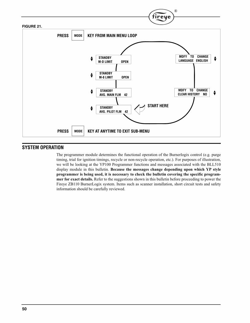
50
®
FIGURE 21.
SYSTEM OPERATION
The programmer module determines the functional operation of the Burnerlogix control (e.g. purgetiming, trial for ignition timings, recycle or non-recycle operation, etc.). For purposes of illustration,we will be looking at the YP100 Programmer functions and messages associated with the BLL510display module in this bulletin. Because the messages change depending upon which YP styleprogrammer is being used, it is necessary to check the bulletin covering the specific program-mer for exact details. Refer to the suggestions shown in this bulletin before proceeding to power theFireye ZB110 BurnerLogix system. Items such as scanner installation, short circuit tests and safetyinformation should be carefully reviewed.
P
START HERE
MODE
STANDBY
M-D LIMIT OPEN
PRESS KEY FROM MAIN MENU LOOP
STANDBY
M-8 LIMIT OPEN
STANDBY
MDFY TO CHANGE
LANGUAGE ENGLISH
MDFY TO CHANGE
CLEAR HISTORY NO
MODEPRESS KEY AT ANYTIME TO EXIT SUB-MENU
AVG. MAIN FLM 42
STANDBY
AVG. PILOT FLM 42

51
®
YP100 Operating Sequence
Start-Up (Normal Cycle)
Note: For direct spark ignited oil burners, substitute the words Main-Oil Valve for Pilot Valve.1. Constant 120 VAC should be available to the Ll-L2 terminals only on the wiring base.2. The operating control circuits (Ll-3) will close, signaling the burner to start its firing sequence.
Terminal 13, fuel valve end switch must be closed.3. The burner/blower motor (terminal M) circuit is energized. The running interlock (limit) circuit
(3-P) will close (e.g. all limits, interlocks, etc. are proven).4. See Figure 2 for sensor wiring.5. When the firing rate motor reaches its open damper position, the Hi Purge switch closes (M-8)
and the prepurge interval of 30* seconds is initiated. Assuming countdown method, the BLV512 will display:
If the M-8 circuit does not close, the program will hold in this position for ten minutes waitingfor it to close. If it does not, the control will lockout. If the M-8 circuit is closed at the start of acycle, the top line of a display will switch to PURGE 20 seconds.
Terminal PTFI MTFI AUTO Post Purge
STANDBY
3 Operating control and pcv < cut in
M Cycle complete
Air flow (terminal P) must close within 10 seconds of HFS (M-8) closing
P
Valve closes in one second
13 (POC) Proof of valve closure
Don't care state
PTFI/MTFI times keypad selectable
6 (PV) 15 s
10 s
5 (IGN/PV) 10 s
W (IGN) 5s
7 (MV)
Programmable time begins (30 sec minimum)
8 (HFS)
LFS must be closed Don't care state
D (LFS) 30 s LFS
PREPRG 00:25HIGH FIRE PURGE
PURGE 00:19HIGH FIRE PURGE

52
®
If the M-8 circuit is not closed at the beginning of a cycle, the top line of a display will switch toPURGE 10 seconds.
6. When the prepurge is completed, the firing rate motor is driven toward the low purge damperposition (10-12 circuit made). The BLV512 will display:
7. Following the minimum 30 second delay (to permit the firing rate motor to get to the low fireposition), the control will wait for the low fire switch (M-D) to close. When it closes, the trial forignition sequence will start. If after ten minutes, the M-D circuit is not closed, the control willlockout unless selected to wait indefinitely.
8. The trial for ignition period begins with Terminals 5, 6 and W being energized simultaneously.This is known as PTFI (Pilot Trial for Ignition). The BLV512 will display:
Unless otherwise selected this period is ten seconds in duration. Terminal W will de-energize after 5seconds. Refer to PTFI*MTFI TIMINGS to determine times selected or timings appropriate for theapplication. The test meter jacks on the ZB110 will provide an indication of the flame signalstrength. The flame signal readout is also available on the alpha-numeric display.
9. With flame proven at the end of PTFI, the main flame trial for ignition (MTFI) period begins.Terminal 7 is energized. The BLV512 will display:
Terminal 5 is de-energized 10 seconds later and Terminal 6 is de-energized after another 5 seconds.10. The firing rate motor is now sent to the automatic modulation position (10-11 circuit made) and
is under the command of the proportional controller. The BLV512 will display:
PURGE 00:10HIGH FIRE PURGE
PURGE 00:24LOW FIRE PURGE
PTFI 00:02IGNITION TIMING
MINIMUM ACCEPTABLE 6mA 6-16NORMAL 7.5 -20mA 20-80
TEST JACKS DISPLAY
PTFI 20FLAME SIGNAL
MTFI 35FLAME SIGNAL
AUTO 40FLAME SIGNAL

53
®
Normal Shutdown
1. When the operating control circuit (L1-3) opens, the main fuel valve is de-energized. The firingrate motor is driven to the low purge position (10-12 circuit made).
2. Following a 15 second post purge, the burner/blower motor is de-energized.
3. The burner is now off and the BLV512 will display
POST PURGE 0:05CYCLE COMPLETE
STANDBYL1-3 OPEN
-
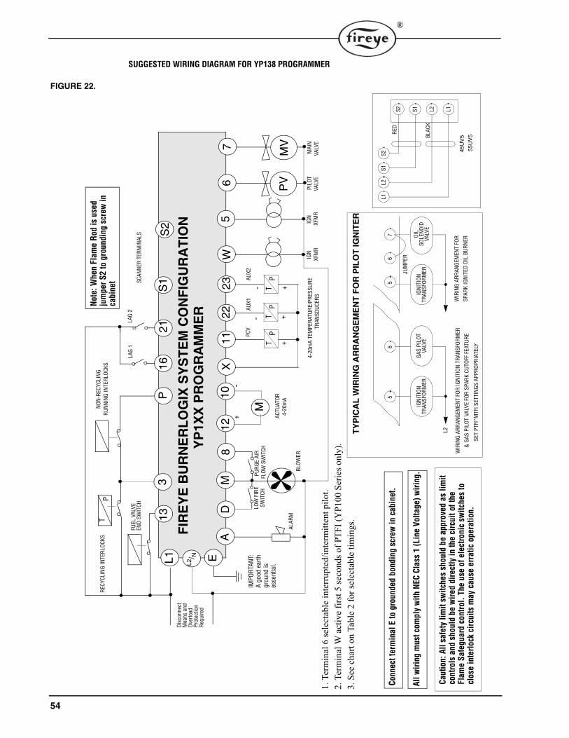
54
®
SUGGESTED WIRING DIAGRAM FOR YP138 PROGRAMMER
FIGURE 22.
12
PV
S2
10D
6X
11W
MA
3P
S1
L1 E
VALV
EM
AIN
IGN
XFM
R
PURG
E AI
RFL
OW S
WIT
CHLO
W F
IRE
SWIT
CH
RECY
CLIN
G IN
TERL
OCKS
NON-
RECY
CLIN
GRU
NNIN
G IN
TERL
OCKS
FIR
EY
E B
UR
NE
RL
OG
IX S
YS
TE
M C
ON
FIG
UR
AT
ION
8
SCAN
NER
TERM
INAL
S
Disc
onne
ct
YP
1XX
PR
OG
RA
MM
ER
TP
L2/ N
13
Mea
ns a
nd
Over
load
Prot
ectio
nRe
quire
d
ALAR
MBL
OWER
FUEL
VAL
VE
END
SWIT
CH
Note
: W
he
n F
lam
e R
od
is
use
d
jum
per
S2 t
o g
roundin
g s
crew
in
cabin
et
IMPO
RTAN
T:A
good
ear
th
grou
nd is
es
sent
ial.
MV7
5 XFM
R IG
NPI
LOT
VAL
VE
1621
LAG
2LA
G 1
2223
MP
TP
TP
T
+-
ACTU
ATOR
4-20
mA
TEM
PERA
TURE
/PRE
SSUR
ETR
ANSD
UCER
S
RED
BLAC
K
45U
V5
L1L2
S1S2
S2 S1 L2 L1
55U
V5
Connect
term
inal
E t
o g
rounded b
ondin
g s
crew
in c
abin
et.
All
wir
ing m
ust
com
ply
wit
h N
EC
Cla
ss 1
(Lin
e V
olt
age)
wir
ing.
Ca
uti
on
: A
ll s
afe
ty l
imit
sw
itch
es
sho
uld
be
app
rove
d a
s li
mit
co
ntr
ols
and s
hould
be w
ired d
irect
ly i
n t
he c
ircu
it o
f th
e
Fla
me S
afe
guard
contr
ol.
The u
se o
f ele
ctro
nic
sw
itch
es
to
close
inte
rlock
cir
cuit
s m
ay
cause
err
ati
c opera
tion.
JUM
PER
WIR
ING
ARRA
NGEM
ENT
FOR
SPAR
K IG
NITE
D OI
L BU
RNER
WIR
ING
ARRA
NGEM
ENT
FOR
IGNI
TION
TRA
NSFO
RMER
& G
AS P
ILOT
VAL
VE F
OR S
PARK
CUT
OFF
FEAT
URE
56
56
7
IGNI
TION
TRAN
SFOR
MER
GAS
PILO
TVA
LVE
IGNI
TION
OIL
SOLE
NOID
VALV
ETR
ANSF
ORM
ER
TY
PIC
AL
WIR
ING
AR
RA
NG
EM
EN
T F
OR
PIL
OT
IGN
ITE
R
L2
SET
PTFI
*MTF
I SET
TING
S AP
PROP
RIAT
ELY
1. T
erm
inal
6 se
lect
able
inte
rrup
ted/
inte
rmitt
ent p
ilot.
2. T
erm
inal
W a
ctiv
e fir
st 5
seco
nds o
f PTF
I (Y
P100
Ser
ies o
nly)
.3.
See
cha
rt on
Tab
le 2
for s
elec
tabl
e tim
ings
.
4-20
mA
PCV
AUX1
AU
X2
-- +
++
55
®
LOCKOUTS
When a safety shutdown occurs, the control will indicate through the LED’s the reason for the lock-out and if equipped will display a lockout message and when in the cycle the lockout occurred. Thealarm circuit (Terminal “A”) will be energized. The non-volatile memory will remember the statusof the control even if a power failure occurs. By momentarily depressing and releasing the reset but-ton on the control or the display keypad, the control can be reset. The button must be held down forone second and then released. Very little force is required to do this. Do not press hard.
SAFETY SHUTDOWN
1. If the running interlock circuit (3-P) does not close, the control will lockout and the blowermotor will be de-energized.
2. If the fuel valve end switch or proof of closure switch connected to Terminal 13 opens duringstandby or purge, the control will lockout.
3. If the running interlock circuit (3-P) opens during a start-up or firing period, all fuel valves willbe de-energized and the control will lockout.
4. If the proven high fire circuit (M-8) has not closed after a ten (10) minute “Hold” period at thestart of prepurge, the control will lockout.
5. If the low fire start circuit (M-D) has not closed after a ten (10) minute “Hold” period at the endof prepurge, the control will lockout.
6. a.) If PROVE 3-P OPEN is selected as YES, and the 3-P circuit is closed at the start of the oper-ating cycle, the control will hold for thirty (30) seconds waiting for the 3-P circuit to open. If,after thirty (30) seconds, the 3-P circuit does not open, the control will lockout.b.) If PROVE M-8 OPEN is selected as YES, and the M-8 circuit is closed at the start of a cycle,the control will hold for thirty (30) seconds for it to open. If, after thirty (30) seconds, the M-8 isstill closed, the control will lockout.c.) If PROVE M-D OPEN is selected as YES, and the M-D switch is closed at the end the highfire purge cycle, the control will hold for thirty (30) seconds for it to open. If, after thirty (30)seconds, the M-D is still closed, the control will lockout.d.) If PROVE M-D TFI is selected as YES, the low fire start switch located between terminals M-D must be closed during PTFI and MTFI.
7. If pilot flame is not detected after the pilot trial for ignition period, the pilot valve and ignitiontransformer will be de-energized and the control will lockout on safety.
8. If main flame is not detected during the main flame trial for ignition period for one FFRT, allfuel valves will be de-energized and the control will lockout on safety.
9. If the main flame fails during a firing cycle, all fuel valves will be de-energized within 1 FFRTand the control will lockout on safety.
10. If flame is detected when the operating control (L1-3) is open, the control will wait sixty (60)seconds and then lockout if flame is still present. If the operating control closes and flame isdetected during purge, the control will drop back to Standby position and de-energize the blowermotor (Term M). If the flame signal goes away within sixty (60) seconds, the control will pro-ceed with a normal start-up. If flame signal is still present after sixty (60) seconds, the controlwill lockout.
11. If the fuel valve end switch connected to Terminal 13 is not closed after 5 seconds into postpurge, the control will lockout on safety.
PROVING 3-P CLOSEDOn cycle start the BurnerLogix proves the 3-P running interlock circuit closed in the followingmanner:
1. At cycle start (L1-3 closes), if the M-8 damper switch is closed, the pre-purge periodbegins and the BurnerLogix will wait up to 20 seconds for the 3-P circuit to close.2. At cycle start (L1-3 closes), if the M-8 damper switch is open, the BurnerLogix will waitup to 10 seconds for the 3-P circuit to close after the M-8 circuit closes. Pre-purge timingbegins after the M-8 closes circuit closes.

56
®
DIAGNOSTIC MESSAGES
RESETTING THE CONTROL
The BurnerLogix systems contain three methods of reset, by push-button located on the ZB chassis/amplifier module, by keypad push-button located on the optional keypad/display module, and bynormally open push-button connected from line voltage (L1) to LAG2 input (terminal 21). LAG2 isa line voltage isolated input. Depressing and releasing the reset button is required. See ALTERNATEUSES FOR LAG2.
Notes:1. Manual Reset is required following any safety shutdown.2. Depressing and releasing the reset button during a cycle will cause the control to shut the burner
down and recycle.3. The YP113 programmer limits the amount of reset attempts to 5 tries. This internal counter gets
reset to 0 when the control reaches the AUTO state and on every application of power.
MESSAGE POSSIBLE CAUSE SOLUTION
CHECK PROGRAMMER
No programmer module plugged into ZB chassis/amplifier module
Remove power, insert programmer, press reset to clear fault
Defective programmer module Remove power, replace programmer module
CHECK CHASSIS Relay feedback error caused by bad wiring
Check all wiring, Re-inspect routing of all wires
Programmer module inserted while power is applied
Cycle power, reset control
Defective opto-coupler on the ZB chassis/amplifier
Replace ZB module
CHECK WIRING Voltage is detected on terminals at improper time
Check system wiring. Measure voltages on input/output terminals
CHECK SCANNER Flame signal detected during shut-ter close time in 45UV5 or 55UV5 scanner
Check power on shutter terminals and/or replace shutter in scanner
Runaway UV tube Replace UV tube, part number 4-314-1
CHECK EXPANSION MODULE
Internal diagnostics within expan-sion module has detected a prob-lem and ceased communications with BurnerLogix control for 3 minutes.
Check that ED580 cable from expansion module to BurnerLogix is plugged in or not damaged, check routing of cable within burner cabinet or check L1-L2 connections to expansion module. Reset control and check STATUS LED on expansion module. Replace YZ300 or YZ320 expansion module or ZB110 chassis/amplifier module.
Defective or unplugged ED580 cable
Assure cable is fully inserted in both BurnerLogix control and Expansion module. Check for damage to cable or connectors.
INVALID YP TYPE Incorrect YP programmer type inserted in BurnerLogix Z control
Only programmer types YP1xx are compatible with BurnerLogix Z model
WAITING FOR DATA Communications to/from display Indicates the display is not communicating properly with chassis. Check that the YP programmer is properly inserted. Check that the cable is not defective and is properly inserted into the con-nectors. In rare instances due to ongoing enhancements to the BurnerLogix family, the display andchassis may not be compatible. Check the date code and engineer-ing code of both sets.

57
®
LOCKOUT CODES
During an alarm condition, the Alarm LED is made to flash at approximately a twice per second rate. The remaining LED’s are illuminated as a coded sequence identifying the reason for thelockout. This remains true if power is removed and then restored in a locked out condition.
Table 5:
LED DISPLAY READOUT
� = ON A B C D E F
LOCKOUT MESSAGE FAN OPEN DAMPER
CLOSE DAMPER
AUTO IGN FLAME
T13 FUEL VALVE END SWITCH OPEN � �M-D LOW FIRE START OPEN � �M-D LOW FIRE START OPEN - PTFI � � �M-D LOW FIRE START OPEN - MTFI � � � �M-D CLOSED � �M-8 CLOSED � �M-8 HIGH PURGE CIRCUIT OPEN �FALSE FLAME-STANDBY � �FLAME FAIL PTFI � � � �FLAME FAIL - MTFI � � � � �FLAME FAIL AUTO � � �3-P RUN INTLK OPEN - PREPURGE � � �3-P RUN INTLK OPEN - PURGE � � �3-P RUN INTLK OPEN-PTFI � �3-P RUN INTLK OPEN-MTFI � � �3-P RUN INTLK CLOSED-STANDBY �3-P RUN INTLK OPEN-AUTO �FUEL VALVE STATE CHANGE �CHECK FUSE � � �CHECK WIRING � � �CHECK SCANNER � � �CHECK PROGRAMMERor INVALID YP � �CHECK CHASSIS �CHECK EXPANSIONMODULE � � � �

58
®
LOCKOUT HISTORY SUB-MENU
The sub-menu "LOCKOUT HISTORY" will display the last ten (10) lockouts, along with the burnercycle and burner hour when the lockout occurred. When the MODE key is pressed, the screen willdisplay the most recent lockout condition and the number of that lockout (e.g. LO #10 represents the10th lockout of that control). The NEXT key will display the Burner Hour, followed by the BurnerCycle when the lockout occurred. The NEXT key will advance to the next lockout, and repeat thesequence listed above. The BACK key can be used to scroll back up through the sub-menu items.The MODE key will exit the sub-menu.
LOCKOUT MESSAGE FAN OPEN DAMPER
CLOSE DAMPER
AUTO IGN FLAME
PCV UNDER RNG � �PCV OVER RNG � �PCV HIGH LIMIT � � �AUX1 UNDER RNG � �AUX1 OVER RNG � � �AUX2 UNDER RNG � � �AUX2 OVER RNG � � � �AUX1 HIGH LIMIT � �AUX2 HIGH LIMIT � � �
LED DISPLAY READOUT
� = ON A B C D E F

59
®
FIGURE 23.
P
START HERE
MODE
LO #9 PURGE
@ BNR HOUR 3
PRESS KEY FROM MAIN MENU LOOP
LO #9 PURGE
3-P INTLK OPEN
LO #10 STANDBY
@ BNR CYCLE 8
LO #10 STANDBY
@ BNR HOUR 3
LO #10 STANDBY
T13 FVES OPEN
LO #9 PURGE
LO #1 PTFI
FLAME FAIL 3
LO #1 PTFI
@ BNR HOUR 1
LO #1 PTFI
@ BNR CYCLE 3
MODEPRESS KEY AT ANYTIME TO EXIT SUB-MENU
@ BNR CYCLE 7
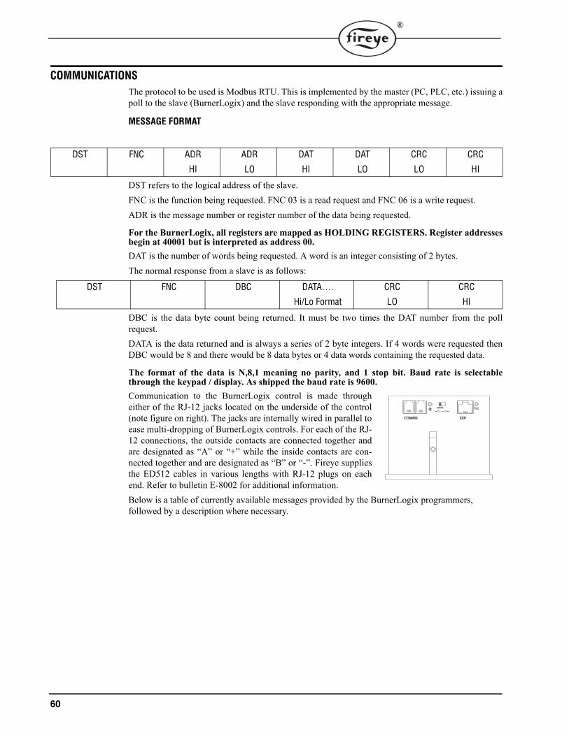
60
®
COMMUNICATIONS
The protocol to be used is Modbus RTU. This is implemented by the master (PC, PLC, etc.) issuing apoll to the slave (BurnerLogix) and the slave responding with the appropriate message.
MESSAGE FORMAT
DST refers to the logical address of the slave. FNC is the function being requested. FNC 03 is a read request and FNC 06 is a write request.ADR is the message number or register number of the data being requested.
For the BurnerLogix, all registers are mapped as HOLDING REGISTERS. Register addressesbegin at 40001 but is interpreted as address 00.DAT is the number of words being requested. A word is an integer consisting of 2 bytes.The normal response from a slave is as follows:
DBC is the data byte count being returned. It must be two times the DAT number from the pollrequest.DATA is the data returned and is always a series of 2 byte integers. If 4 words were requested thenDBC would be 8 and there would be 8 data bytes or 4 data words containing the requested data.
The format of the data is N,8,1 meaning no parity, and 1 stop bit. Baud rate is selectablethrough the keypad / display. As shipped the baud rate is 9600.Communication to the BurnerLogix control is made througheither of the RJ-12 jacks located on the underside of the control(note figure on right). The jacks are internally wired in parallel toease multi-dropping of BurnerLogix controls. For each of the RJ-12 connections, the outside contacts are connected together andare designated as “A” or “+” while the inside contacts are con-nected together and are designated as “B” or “-”. Fireye suppliesthe ED512 cables in various lengths with RJ-12 plugs on eachend. Refer to bulletin E-8002 for additional information.Below is a table of currently available messages provided by the BurnerLogix programmers, followed by a description where necessary.
DST FNC ADR
HI
ADR
LO
DAT
HI
DAT
LO
CRC
LO
CRC
HI
DST FNC DBC DATA….
Hi/Lo Format
CRC
LO
CRC
HI
COMMSCOMMS EXPEXP
RUN/CHKRUN/CHK

61
®
MODBUS MESSAGE TABLE
Table 6:
HOLDING REGISTER
MESSAGEADDRESS
WORD REQUESTED
WORDRESPONSE
VALUE
40001 00 1 STATUS 83 (053H) = RUN;202 (0CAH) = LOCKOUT
40002 01 1 MSGN Current message being displayed (see Table 9)
40003 02 1 GSTAT Defines Timer Type40004 03 1 TIMER Time in seconds40005 04 1 FLAME Flame Signal40006 05 1 LOGSTAT Current logic module, PURGE, PTFI, AUTO
(see Table 8)40007 06 1 INPUTS Input limits state40008 07 1 OUTPUTS Output relays state40009 08 2 SYSMINS System on minutes40011 10 2 BNRMINS Burner on minutes40013 12 2 CYCLES Completed Burner Cycles40015 14 1 LOCKOUT COUNT Stored Lockout Count
40016 15 6LOCKOUT HISTORY Beginning of Last 10 Lockouts
Most Recent Lockout DataReturns complete lockout description of
stored lockout history.
Includes lockout message (1), lockout module (1), @ burner hours (2), and @ burner cycles (2)s
40022 21 6 2nd Most Recent Lockout Data40028 27 6 3rd Most Recent Lockout Data40034 33 6 4th Most Recent Lockout Data40040 39 6 5th Most Recent Lockout Data40046 45 6 6th Most Recent Lockout Data40052 51 6 7th Most Recent Lockout Data40058 57 6 8th Most Recent Lockout Data40064 63 6 9th Most Recent Lockout Data40070 69 6 10th Most Recent Lockout Data40076
���
40079
75���
78
4
40080���
40090
79���
89
11N/A Reserved for Fireye use
INTERLOCK ANNUNCIATOR
40901 900 1 - 3YZ300 Interlock
Annunciator registers(see Table 7)
Returns lower, middle and upper interlock annunciator (YZ300) registers.
40902 901 1 - 2 Returns middle and upper interlock annunciator (YZ300) registers.
40903 902 1 Returns upper interlock annunciator (YZ300) register.

62
®
BOILER OPERATING PARAMETERS
40100 99 1 Calibration Constant (used to normalize A/D readings)
READ Only Values
40101 100 1 Primary sensor Raw A/D reading40102 101 1 AUX 1 sensor Raw A/D reading40103 102 1 AUX 2 sensor Raw A/D reading40104 103 1 LEAD / LAG status40105 104 1 Current Modulation Rate40106 105 1 LAGx START DELAY40107 106 1 Current Control Variable STANDBY = 0; PCV = 1; AUX 1 = 2
40110 109 1 Primary Sensor Use
Except as noted, all boiler parameters are readable,
FNC 03 and writeable, FNC 06.Only word writes are provided.
Consult factory orrefer to www.fireye.comfor acceptable minimum
and maximum values
40111 110 1 Primary Sensor Type40112 111 1 Primary Sensor Set Point40113 112 1 Primary Sensor Cut In40114 113 1 Primary Sensor Cut Out40115 114 1 Primary Sensor Mod Range40116 115 1 Primary Sensor Marginal Alarm40117 116 1 Primary Sensor Limit Alarm
40120 119 1 AUX 1 Sensor Use40121 120 1 AUX 1 Sensor Type40122 121 1 AUX 1 Sensor Set Point40123 122 1 AUX 1 Sensor Cut In40124 123 1 AUX 1 Sensor Cut Out40125 124 1 AUX 1 Sensor Mod Range40126 125 1 AUX 1 Sensor Marginal Alarm40127 126 1 AUX 1 Sensor Limit Alarm
40130 129 1 AUX 2 Sensor Use40131 130 1 AUX 2 Sensor Type40132 131 1 AUX 2 Sensor Set Point40133 132 1 AUX 2 Sensor Cut In40134 133 1 AUX 2 Sensor Cut Out40135 134 1 AUX 2 Sensor Mod Range40136 135 1 AUX 2 Sensor Marginal Alarm40137 136 1 AUX 2 Sensor Limit Alarm
40140 139 1 LAG 1 Lag Mode40141 140 1 LAG 1 Start Delay40142 141 1 LAG 1 Lead to Lag Delay40143 142 1 LAG 1 Sensor Set Point40144 143 1 LAG 1 Sensor Cut In40145 144 1 LAG 1 Sensor Cut Out40146 145 1 LAG 1 Sensor Mode Range40147 146 1 LAG 1 Mod Max
HOLDING REGISTER
MESSAGEADDRESS
WORD REQUESTED
WORDRESPONSE
VALUE

63
®
Interpreting Z Model Modbus ValuesThe calibration constant is factory set to achieve the proper reading at 4mA and 20 mA. It is basedon the actual hardware in the product and the A/D reference voltage in the micro controller at thetime of manufacture. It has a range of 819 to 860 counts and is accessible from register 99 (40100).This should be the first value read in and used for all pressure and temperature calculations.The calibration constant is used to convert the actual sensor reading to meaningful pressure or tem-perature values. The pressure sensors are all 0 psig at the 4 mA and below reading. For the two tem-perature sensors, 32-350 and 32-752, the maximum range of each is 318 and 720 degreesrespectively.If the calibration constant represents 20 mA input then 1/5 of that represents 4 mA input or 0.2 timesthe calibration constant. To convert a pressure or temperature reading to actual units, use the following:(([Reading /calibration constant] - 0.2) / 0.8) * Sensor Range) + Sensor Offset where Reading is thevalue returned from modbus register 4101, 40102 or 40103.
40150 149 1 LAG 2 Lag Mode
Except as noted, all boiler parameters are readable,
FNC 03 and writeable, FNC 06.Only word writes are provided.
Consult factory orrefer to www.fireye.comfor acceptable minimum
and maximum values
40151 150 1 LAG 2 Start Delay40152 151 1 LAG 2 Lead to Lag Delay40153 152 1 LAG 2 Sensor Set Point40154 153 1 LAG 2 Sensor Cut In40155 154 1 LAG 2 Sensor Cut Out40156 155 1 LAG 2 Sensor Mode Range40157 156 1 LAG 2 Mod Max
40160 159 1 Thermal Shock Method40161 160 1 Thermal Shock Start Point40162 161 1 Thermal Shock Exit Point40163 162 1 Thermal Shock Low Fire Minimum40164 163 1 Thermal Shock Override Time
40170 169 1 Modulation Mode40171 170 1 Integral Gain40172 171 1 Derivative Gain40173 172 1 Modulation Maximum Position40174 173 1 Units of Measurement40175 174 1 Manual Mod Position40176 175 1 PassWord Level 140177 176 1 PassWord Level 2
SENSOR TYPE SENSOR RANGE SENSOR OFFSETTS350-2, -4, -8 318 32TS352-2, -4, -8 720 32
BLPS-15 15 0BLPS-30 30 0
BLPS-200 200 0BLPS-300 300 0
HOLDING REGISTER
MESSAGEADDRESS
WORD REQUESTED
WORDRESPONSE
VALUE
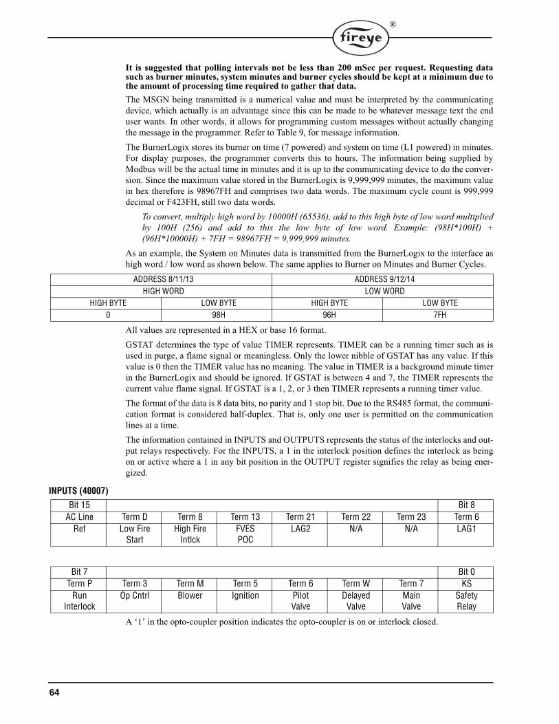
64
®
It is suggested that polling intervals not be less than 200 mSec per request. Requesting datasuch as burner minutes, system minutes and burner cycles should be kept at a minimum due tothe amount of processing time required to gather that data.The MSGN being transmitted is a numerical value and must be interpreted by the communicatingdevice, which actually is an advantage since this can be made to be whatever message text the enduser wants. In other words, it allows for programming custom messages without actually changingthe message in the programmer. Refer to Table 9, for message information.The BurnerLogix stores its burner on time (7 powered) and system on time (L1 powered) in minutes.For display purposes, the programmer converts this to hours. The information being supplied byModbus will be the actual time in minutes and it is up to the communicating device to do the conver-sion. Since the maximum value stored in the BurnerLogix is 9,999,999 minutes, the maximum valuein hex therefore is 98967FH and comprises two data words. The maximum cycle count is 999,999decimal or F423FH, still two data words.
To convert, multiply high word by 10000H (65536), add to this high byte of low word multipliedby 100H (256) and add to this the low byte of low word. Example: (98H*100H) +(96H*10000H) + 7FH = 98967FH = 9,999,999 minutes.
As an example, the System on Minutes data is transmitted from the BurnerLogix to the interface ashigh word / low word as shown below. The same applies to Burner on Minutes and Burner Cycles.
All values are represented in a HEX or base 16 format.GSTAT determines the type of value TIMER represents. TIMER can be a running timer such as isused in purge, a flame signal or meaningless. Only the lower nibble of GSTAT has any value. If thisvalue is 0 then the TIMER value has no meaning. The value in TIMER is a background minute timerin the BurnerLogix and should be ignored. If GSTAT is between 4 and 7, the TIMER represents thecurrent value flame signal. If GSTAT is a 1, 2, or 3 then TIMER represents a running timer value.The format of the data is 8 data bits, no parity and 1 stop bit. Due to the RS485 format, the communi-cation format is considered half-duplex. That is, only one user is permitted on the communicationlines at a time.The information contained in INPUTS and OUTPUTS represents the status of the interlocks and out-put relays respectively. For the INPUTS, a 1 in the interlock position defines the interlock as beingon or active where a 1 in any bit position in the OUTPUT register signifies the relay as being ener-gized.
INPUTS (40007)
A ‘1’ in the opto-coupler position indicates the opto-coupler is on or interlock closed.
ADDRESS 8/11/13 ADDRESS 9/12/14HIGH WORD LOW WORD
HIGH BYTE LOW BYTE HIGH BYTE LOW BYTE0 98H 96H 7FH
Bit 15 Bit 8AC Line Term D Term 8 Term 13 Term 21 Term 22 Term 23 Term 6
Ref Low FireStart
High FireIntlck
FVES POC
LAG2 N/A N/A LAG1
Bit 7 Bit 0Term P Term 3 Term M Term 5 Term 6 Term W Term 7 KS
Run Interlock
Op Cntrl Blower Ignition PilotValve
DelayedValve
MainValve
SafetyRelay
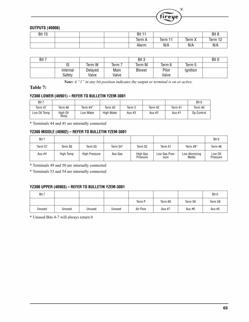
65
®
OUTPUTS (40008)
Note: A “1” in any bit position indicates the output or terminal is on or active.Table 7:
YZ300 LOWER (40901) – REFER TO BULLETIN YZEM-3001
* Terminals 44 and 45 are internally connected
YZ300 MIDDLE (40902) – REFER TO BULLETIN YZEM-3001
* Terminals 49 and 50 are internally connected* Terminals 53 and 54 are internally connected
YZ300 UPPER (40903) – REFER TO BULLETIN YZEM-3001
* Unused Bits 4-7 will always return 0
Bit 15 Bit 11 Bit 8Term A Term 11 Term X Term 12Alarm N/A N/A N/A
Bit 7 Bit 3 Bit 0IS Term W Term 7 Term M Term 6 Term 5
InternalSafety
DelayedValve
MainValve
Blower PilotValve
Ignition
Bit 7 Bit 0
Term 47 Term 46 Term 44* Term 43 Term 3 Term 42 Term 41 Term 40
Low Oil Temp High Oil Temp
Low Water High Water Aux #3 Aux #2 Aux #1 Op Control
Bit 7 Bit 0
Term 57 Term 56 Term 55 Term 54* Term 52 Term 51 Term 49* Term 48
Aux #4 High Temp High Pressure Aux Gas High Gas Pressure
Low Gas Pres-sure
Low Atomizing Media
Low Oil Pressure
Bit 7 Bit 0
Term P Term 60 Term 59 Term 58
Unused Unused Unused Unused Air Flow Aux #7 Aux #6 Aux #5
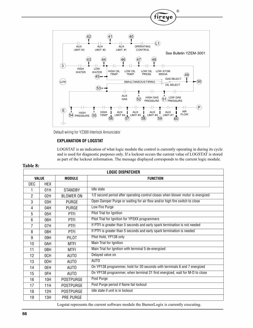
66
®
EXPLANATION OF LOGSTAT
LOGSTAT is an indication of what logic module the control is currently operating in during its cycle and is used for diagnostic purposes only. If a lockout occurs the current value of LOGSTAT is stored as part of the lockout information. The message displayed corresponds to the current logic module.
Table 8:
Logstat represents the current software module the BurnerLogix is currently executing.
LOGIC DISPATCHER
VALUE MODULE FUNCTION
DEC HEX1 01H STANDBY Idle state
2 02H BLOWER ON 1/2 second period after operating control closes when blower motor is energized
3 03H PURGE Open Damper Purge or waiting for air flow and/or high fire switch to close
4 04H PURGE Low Fire Purge
5 05H PTFI Pilot Trial for Ignition
6 06H PTFI Pilot Trial for Ignition for YP3XX programmers
7 07H PTFI If PTFI is greater than 5 seconds and early spark termination is not needed
8 08H PTFI If PTFI is greater than 5 seconds and early spark termination is needed
9 09H PILOT Pilot Hold, YP138 only
10 0AH MTFI Main Trial for Ignition
11 0BH MTFI Main Trial for Ignition with terminal 5 de-energized
12 0CH AUTO Delayed valve on
13 0DH AUTO AUTO
14 0EH AUTO On YP138 programmer, hold for 20 seconds with terminals 6 and 7 energized
15 0FH AUTO On YP138 programmer, when terminal 21 first energized, wait for M-D to close
16 10H POSTPURGE Post Purge
17 11H POSTPURGE Post Purge period if flame fail lockout
18 12H POSTPURGE Idle state if unit is in lockout
19 13H PRE PURGE
AUXLIMIT #3
AUXLIMIT #2
AUXLIMIT #1
OPERATINGCONTROL
HIGHWATER
LOWWATER
42 41 40
L2/N
HIGH OILTEMP.
LOW OILTEMP
LOW OILPRESS
46 47
AIRFLOW
AUXLIMIT #7
60
AUX LIMIT #6
AUXLIMIT #5
AUXLIMIT #4
HIGHPRESSURE
59585756
43 44
AUXGAS HIGH GAS
PRESSURE52
50
LOW GAS PRESSURE51
LOW ATOMMEDIA
48
53
45
OIL SELECT
GAS SELECT49
SIMULTANEOUS FIRING
54HIGHTEMP55
L1
3
EP
See Bulletin YZEM-3001
Default wiring for YZ300 Interlock Annunciator

67
®
The BurnerLogix outputs the current displayed message as well as the historical lockout messages asnumbers. The table below correlates the message number with the actual displayed text message.
Table 9: DEC HEX STATE BURNERLOGIX MESSAGES
1 1 L M-D LOW LIMIT OPEN - AUTO
2 2 H HOLD FALSE FLAME- STANDBY
3 3 R LOW FIRE PURGE
4 4 H HOLD M-8 LIMIT OPEN - PURGE
5 5 H See Interlock Annunciation Message Table
6 6 H M-D LOW LIMIT - AUTO
7 7 L LOCKOUT FLAME FAIL - PTFI
8 8 R T16 INPUT CLOSED
9 9 H HOLD M-D LIMIT OPEN
10 A R IGNITION TIMING - PTFI
11 B C CHECK FLAME SIGNAL - MTFI
12 C R FLAME SIGNAL - AUTO
13 D R CYCLE COMPLETE - POST PURGE
14 E R L1-3 OPEN
91 E R L1-3 CLOSED (Z MODEL ONLY)
15 F R T21 INPUT CLOSED
16 10 L LOCKOUT M-D LIMIT OPEN - PTFI
17 11 L LOCKOUT M-8 LIMIT OPEN
18 12 L LOCKOUT M-D LIMIT OPEN
19 13 L LOCKOUT FLAME FAIL - MTFI
20 14 L LOCKOUT FALSE FLAME
21 15 L LOCKOUT 3-P INTLK OPEN (PURGE)
22 16 L LOCKOUT 3-P INTLK CLOSED
23 17 H HOLD 3-P INTLK CLOSED - STANDBY
24 18 H HIGH FIRE PURGE
25 19 L LOCKOUT M-D LIMIT OPEN - MTFI
26 1A L LOCKOUT 3-P INTLK OPEN -AUTO
27 1B L LOCKOUT 3-P INTLK OPEN - MTFI
28 1C L LOCKOUT 3-P INTLK OPEN - PTFI
29 1D L LOCKOUT T13 FVES OPEN - STANDBY
30 1E L LOCKOUT 3-P INTLK OPEN - PREPURGE
31 1F C CHECK FLAME SIGNAL - PTFI
32 20 C CHECK M-8 HI LIMIT (HI FIRE PURGE)
33 21 C CHECK M-D LOW LIMIT (LO FIRE START)
34 22 R FLAME SIGNAL- PTFI
35 23 C CHECK LOW FIRE SIGNAL - AUTO
36 24 R FLAME SIGNAL - MTFI
37 25 L LOCKOUT FLAME FAIL (AUTO)
38 26 H HOLD 3-P INTLK OPEN - PREPURGE
39 27 L LOCKOUT FUEL VALVE STATE CHANGE
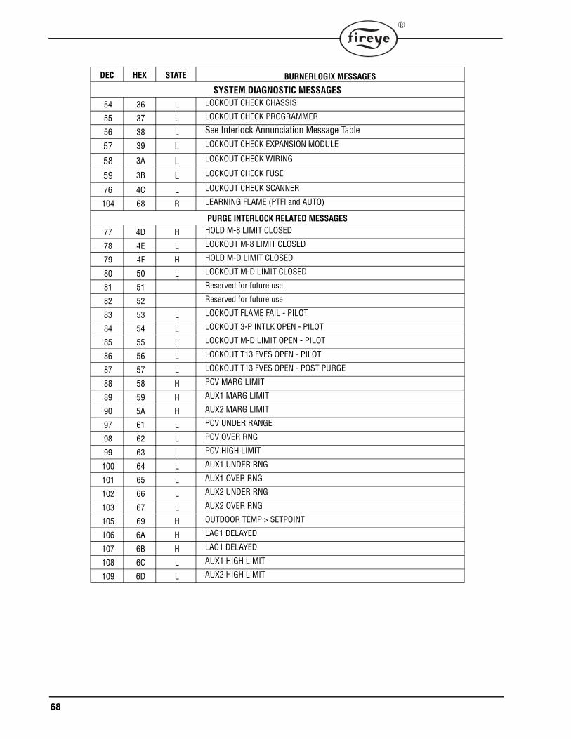
68
®
SYSTEM DIAGNOSTIC MESSAGES
54 36 L LOCKOUT CHECK CHASSIS
55 37 L LOCKOUT CHECK PROGRAMMER
56 38 L See Interlock Annunciation Message Table
57 39 L LOCKOUT CHECK EXPANSION MODULE
58 3A L LOCKOUT CHECK WIRING
59 3B L LOCKOUT CHECK FUSE
76 4C L LOCKOUT CHECK SCANNER
104 68 R LEARNING FLAME (PTFI and AUTO)
PURGE INTERLOCK RELATED MESSAGES
77 4D H HOLD M-8 LIMIT CLOSED
78 4E L LOCKOUT M-8 LIMIT CLOSED
79 4F H HOLD M-D LIMIT CLOSED
80 50 L LOCKOUT M-D LIMIT CLOSED
81 51 Reserved for future use
82 52 Reserved for future use
83 53 L LOCKOUT FLAME FAIL - PILOT
84 54 L LOCKOUT 3-P INTLK OPEN - PILOT
85 55 L LOCKOUT M-D LIMIT OPEN - PILOT
86 56 L LOCKOUT T13 FVES OPEN - PILOT
87 57 L LOCKOUT T13 FVES OPEN - POST PURGE
88 58 H PCV MARG LIMIT
89 59 H AUX1 MARG LIMIT
90 5A H AUX2 MARG LIMIT
97 61 L PCV UNDER RANGE
98 62 L PCV OVER RNG
99 63 L PCV HIGH LIMIT
100 64 L AUX1 UNDER RNG
101 65 L AUX1 OVER RNG
102 66 L AUX2 UNDER RNG
103 67 L AUX2 OVER RNG
105 69 H OUTDOOR TEMP > SETPOINT
106 6A H LAG1 DELAYED
107 6B H LAG1 DELAYED
108 6C L AUX1 HIGH LIMIT
109 6D L AUX2 HIGH LIMIT
DEC HEX STATE BURNERLOGIX MESSAGES

69
®
R = RUN H = HOLD L = LOCKOUT C = CHECK
DEC HEX STATE TERMINAL YZ300 INTERLOCK ANNUNCIATOR LOCKOUT MESSAGES
41 29 L 3-43 HIGH WATER
42 2A L 43-44 LOW WATER
43 2B L 51-52 HIGH GAS PRESSURE
44 2C L 50-51 LOW GAS PRESSURE
92 5C L 52-54 AUX GAS
45 2D L 47-48 LOW OIL PRESSURE
56 38 L 44-46 HIGH OIL TEMPERATURE
46 2E L 46-47 LOW OIL TEMPERATURE
47 2F L 48-50 LOW ATOMIZING MEDIA
48 30 L 54-55 HIGH PRESSURE
49 31 L 55-56 HIGH TEMPERATURE
50 32 L 56-57 AUX #4 OPEN
51 33 L 57-58 AUX #5 OPEN
52 34 L 58-59 AUX #6 OPEN
53 35 L 59-60 AUX #7 OPEN
40 28 L 60-P AIR FLOW OPEN
DEC HEX STATE TERMINAL YZ300 INTERLOCK ANNUNCIATOR HOLD MESSAGES
94 5E H L1-40 OP CONTROL OPEN
60 3C H 40-41 L1-3 AUX #1 OPEN
61 3D H 41-42 L1-3 AUX #2 OPEN
62 3E H 42-3 L1-3 AUX #3 OPEN
63 3F H-C 3-43 HIGH WATER
64 40 H-C 43-44 LOW WATER
65 41 H-C 51-52 HIGH GAS PRESSURE
66 42 H-C 50-51 LOW GAS PRESSURE
95 5F H-C 52-54 AUX GAS
67 43 H-C 47-48 LOW OIL PRESSURE
96 60 H-C 44-46 HIGH OIL TEMPERATURE
68 44 H-C 46-47 LOW OIL TEMPERATURE
69 45 H-C 48-50 LOW ATOMIZING MEDIA
70 46 H-C 54-55 HIGH PRESSURE
71 47 H-C 55-56 HIGH TEMPERATURE
72 48 H-C 56-57 AUX #4 OPEN
73 49 H-C 57-58 AUX #5 OPEN
74 4A H-C 58-58 AUX #6 OPEN
75 4B H-C 59-60 AUX #7 OPEN
5 5 H-C 60-P AIR FLOW OPEN

70
®
OPERATIONAL FEATURES
4-20 mA TEST JACKS
For all amplifier types, the BurnerLogix provides 4-20 mA testjacks to represent the flame signal strength. The test jacks arelocated on the underside of the ZB module (pictured at right).The ‘+’ jack is located next to COMMS port jack and the ‘–‘ jackis located next to the EXP port. Use caution so as NOT to plugthe ‘–‘ jack into the EXP port. The test jacks accept standardplugs having a diameter of 0.078” (2mm). The maximum inputimpedance allowed is 100 ohms. The chart below correlates thetest jack current to the numerical value shown on the display.
FIGURE 24.
COMMSCOMMS EXPEXP
RUN/CHKRUN/CHK
4
6
8
10
12
14
16
18
20
0 10 13 16 20 24 28 33 54 80
DISPLAY READING
4-2
0 m
A T
ES
T J
AC
K
38 40

71
®
CHECK-RUN SWITCH
The Check-Run switch is located on the underside of the ZBChassis Module (note drawing on right) and can be used to stopthe control in its firing sequence at any time in the burnersequence. It is designed to aid in set-up, start-up and check-out ofthe burner and its associated interlocks.Following are the modes of operation:1. When power is applied to the control (Ll-L2) and the operat-
ing control circuit is closed (L1-3), the purge period beginsand the firing rate motor is sent to the Hi Purge position. If the Check-Run Switch is moved tothe Check position before the open damper 30 second purge period ends, the control will dis-play:
The control will hold in this position indefinitely to allow the operator to make interlock switch andlinkage adjustments. To continue in the cycle, move the Check-Run switch to Run to allow the con-trol to advance.2. If the Check-Run switch is moved to the Check position after the open damper purge period, but
before low fire start period ends, the control will display:
The control will hold in this position indefinitely to allow the operator to make interlock switch andlinkage adjustments. To continue the cycle, moving the Check-Run Switch to Run will allow thecontrol to advance.3. During the PTFI period, switching to the Check position will stop the program in the PTFI
period, allowing for pilot and/or scanner alignment adjustments to be made. The control willdisplay:
It will hold in this position indefinitely as long as the flame signal strength is above the threshold of10. If it drops below 10 for thirty (30) consecutive seconds, lockout will occur and the message onthe display will read Flame Fail PTFI.4. During the MTFI period, switching to the Check position will stop the program in the MTFI
period. At this point it may be useful to inspect the position of the main flame at the burner head.Depending on where the switch is placed in check and depending on the selection ofPTFI*MTFI TIMING, terminals 5, 6 and 7 could be energized simultaneously. The control willdisplay:
If the unit is left in Check for longer than 2 minutes, the control will automatically advance toAUTO.
5. Switching from run to check during the burner on period will drive the modulator circuit to lowfire. This allows for low fire fuel-air adjustments and holding the burner at low fire. Consultyour boiler/burner instructions for low fire hold firing recommendations. The control will dis-play:
COMMSCOMMS EXPEXP
RUN/CHKRUN/CHK
CHECK 00:24HIGH FIRE PURGE
CHECK 00:24LOW FIRE PURGE
CHECK 35FLAME SIGNAL
CHECK 35FLAME SIGNAL
CHECK 35LOW FIRE SIGNAL

72
®
OPERATIONAL TEST
Close the manual main shut-off fuel valve.1. Recheck all limit circuit wiring for proper operation and correct connection. 2. Confirm that the automatic main fuel valves are wired to terminal “7.” 3. Power the control and electronically check the proper sequence of operation according to the
YP100 Operating Sequence shown on page 51 of this bulletin.4. After assuring yourself that all interlocks and valves are properly wired and that the sequence of
operation is correct, open the manual main shut-off fuel valve and proceed cautiously throughthe boiler light off process. Check all safety interlocks for proper shut down of the boiler.
When the installation and all burner adjustments are completed, the entire burner control systemshould be tested in accordance with the burner manufacturer’s instructions. The procedure shouldverify the correct operation of:1. Each operating control (temperature, pressure, etc.).2. Each limit switch (temperature, pressure, low water cutoff, etc.).3. Each interlock switch (airflow switch, high and low fuel pressure or temperature switches, purge
and low fire start switches, fuel valve proof of closure interlock, etc.).4. Pilot flame failure response and lockout. 5. Main flame failure response and lockout. 6. Tight shut off of all fuel valves.
Voltage TestA Voltage Check is necessary to identify a potential problem with the supply to the control. Thiscould be caused by an improperly sized or faulty transformer, faulty load coils or low entry voltage.Follow this procedure:1. Monitor the L1-L2 supply throughout a complete burner cycle. The acceptable voltage range is
102V-132V. At no time during the cycle should the voltage dip below the minimum level.2. Check other load terminal (M/L2, 5/L2, 6/L2, 7/L2) for voltage at improper times or improper
values.
TEST CHECKOUT PROCEDURES
Normal Pilot Flame Test
1. At the start of PTFI, place the RUN/CHK switch in the CHK position.2. Observe the pilot flame signal on the display. If the average signal is below the minimum of 10,
readjust the pilot flame or realign the flame detector.3. During the pilot flame test, if flame is not detected for a continuous 30 seconds, the control will
lockout. To re-establish the pilot flame trial for ignition (PTFI), manual reset of the lockoutswitch is required, and a complete prepurge accomplished.
4. When UV flame detection is used, a test is required to verify that UV radiation from the ignitionspark is not being detected. To accomplish this, manually shut off both pilot and main fuels. Ini-tiate a normal start-up, and when the PTFI display comes on, observe the display which should
WARNING: Before testing the control operation on the boiler, close the manual main shut-off fuel valve. Failure to do this may cause injury or property damage.
CAUTION: LIVE VOLTAGE IS NECESSARY TO PERFORM THIS TEST.
CAUTION: Before making a pilot flame test, manually shut off the fuel supply to the mainburner.
73
®
read no signal more than 4. If more than 4 is observed, realign the UV scanner, and/or shield thespark from the scanner’s view.
5. With all methods of flame detection, check pilot flame failure response by manually shutting offthe pilot fuel and then initiate a normal start-up. With no pilot flame present, the control will de-energize the pilot assembly at the end of the trial for ignition interval, and the control will lock-out. Also check to verify that the ignition spark does not cause an electrical interference oninfrared or flame rod applications.
Main Flame TestNote: This test requires an interrupted pilot (a pilot that shuts off after main flame has been estab-lished).1. Proceed through a normal startup. After the pilot flame is shut off, observe the reading on the
display. If the signal reading is low, readjust main flame or realign detector.2. Check main flame failure protection by manually shutting off the main fuel supply. Within 4
seconds after main flame goes out, the fuel valve will be de-energized. The alarm circuit will beenergized following safety lockout.
Minimum Pilot Test
This test assures that the flame detector will not detect a pilot flame too small to reliably light off themain flame. The test should be made on every new installation and following any repositioning orreplacement of the flame detector. This procedure should not be used on a direct spark ignitedburner.1. Turn off the main fuel supply manually.2. At the start of PTFI, place the Check-run switch in the check position.3. Reduce the fuel supply to the pilot until the display reads below 10.4. Slowly increase the fuel to the pilot until the display reads 10. This is minimum pilot flame that
the flame detector will reliably detect.5. Place the Check-run switch in the Run position. When the main fuel safety shut-off valve is
energized, slowly open the manual main fuel valve. 6. Observe the light-off of the main flame. It must be smooth and normal.
7. Repeat the test until a reliable and smooth light-off occurs with the minimum pilot.8. After this test is completed, increase the fuel to the pilot to its normal setting.
CAUTION: The minimum pilot test must be accomplished by a trained and qualifiedburner technician
CAUTION: If the main flame does not ignite immediately, shut off the main fuel. Realignthe detector to require larger minimum pilot flame

74
®
FIGURE 25.
Scanner WiringCare should be taken to see that ignitor cables and scanner cables are routed away from one anotheron all installations. These cables, when crossed or run together, may interfere with the proper opera-tion of the flame safeguard control.If you are experiencing erratic operation or inappropriate characters on the display during the trial forignition period, the cause is likely to be ignitor noise. Check for worn ignitor cable insulation, brokenor cut insulation or loose connectors at the electrode and transformers
SUGGESTED GROUNDING RULES
The BurnerLogix system, being microprocessor based, requires a ground system that provides azero-voltage reference. The voltage measured from L2 to all other terminals except L1 should be 0volts.1. The most effective ground is to run the ground wire in the same raceway as the hot and neutral
from the main distribution service panel (not intermediate sub-panels) to the burner controlpanel and insure that this ground wire is well bonded to the control panel.
2. The wiring base of the BurnerLogix must have earth ground providing a connection between thesub-base and the control panel or the burner.
3. The earth ground wire must be capable of conducting the current to blow the 20A fuse in eventof an internal short circuit. A number 14 AWG copper conductor is adequate, wide straps orbrackets are preferred rather than lead wires.
4. The ground path needs to be low impedance (less than 1 ohm) to the equipment frame which inturn needs a low impedance to earth ground. For a ground path to be low impedance at RF fre-quencies, the connection must be made with minimum length conductors having maximum sur-face areas.
5. All connections should be free of nonconductive coatings and protected against rust. 6. Utilizing conduit as a means of providing a ground must be avoided. 7. Installing ground rods at the burner control panel defeats the purpose of a single point ground as
described above and could also present a safety hazard.
InstallationDo not run high voltage ignition transformer wires in the same conduit with flame detection wiring.Do not run scanner wires in a conduit with line voltage circuits. Ensure the frame of the ignitiontransformer is securely connected to control panel frame or preferably the burner frame.The BurnerLogix chassis (ZB110) contains a transient suppressing device connected internallyacross hot and neutral and to earth ground, terminal E. For this to be effective terminal E or the greenwire in the pig-tail wiring base must be well grounded.
MAINFLAME
REFRACTORY
MAINBURNER
PILOTFLAME
SCANNER
PILOTBURNER
INSUFFICIENT PILOT
MAINFLAME
MAINBURNER
PILOTFLAME
SCANNER
PILOTBURNER
MINIMUM PILOT
MAINFLAME
MAINBURNER
PILOTFLAME
SCANNER
PILOTBURNER
NORMAL PILOT
REFRACTORYREFRACTORY

75
®
Remote DisplayTo locate the display remotely from the BurnerLogix control, mounting kits are available. These areFireye part numbers 129-178-4 or 129-178-8. Each kit contains a gasket, hardware to mount the dis-play and a 4 or 8 foot cable. Care must be taken not to route the ED580 cable in close proximity to any starter motor contactorslocated in the control panel or across any high voltage ignition wires. Refer to Fireye bulletin E-8002for proper installation.
CommunicationsWhen interfacing Fireye controls to a communication system, be it a PLC or other microprocessorbased device, ferrite cores should also be utilized. Proper twisted shielded pair cable must be uti-lized. In a multi-drop system, the shields should be tied together within a cabinet and not to anyground point. The shield at the source end of the cable of the multi-drop connection can then be ter-minated to ground. Source end is defined as the originating end of the communication systemCare must be taken not to route communication cables in close proximity to any starter motor contac-tors located in the control panel or across any high voltage ignition wires. Refer to Fireye bulletin E-8002 for proper installation.
ScannersThe armored cable supplied with the Ultra-Violet and Infrared scanners should be connected toequipment by means of a good mechanical connection such as a conduit fitting. It may be necessaryto utilize heat insulator (P/N 35-69) to isolate the sensing end of the scanner from boiler ground.Care must be taken not to route the scanner cable across the high voltage ignition cable. The highenergy ignition cable should be checked periodically for cracking, connections and aging. In applications using flame rod units, it may be beneficial to route a separate return wire from the S2terminal to the flame rod assembly. This will minimize the effects of transient currents flowing intothe BurnerLogix.In all cases, scanner wires should be routed in separate conduit and not joined with any high voltageAC or ignition cables.
MaintenancePeriodically, the spark electrode should be inspected for proper gapping and cracked ceramics. Atignition time, the high energy from the ignition transformer will attempt to conduct to the point ofleast resistance and with an improper spark gap, where the conduction takes place will no longer becontrolled.The VA rating of the control transformer must be sized to handle the inrush currents of the pilot sole-noid and ignition transformer at PTFI and then the inrush currents of the main fuel valve assembly atMTFI time.Inspect neatness of wiring in junction boxes and cabinets. It is best to have connections short anddirect and also not having wires bunched up and tied off. Also, connections should be periodicallyinspected for tightness and corrosionType 48PT2 Infrared and Type UV1A, UV2, 45UV5 Ultraviolet ScannersThe viewing area of the scanner must be kept clean. Even a small amount of contamination willreduce the flame signal reaching the detector by a measurable amount. Wipe the viewing area rou-tinely using a soft cloth dampened with concentrated detergent.— Type 48PT2 Scanners include a replaceable #4-263-1 Firetron cell.— Type 45UV5 Scanners include a replaceable #4-314-1 UV tube.Type 69ND1 Flame RodThe flame rod and its insulator should be kept clean by washing routinely with soap and water. Rodsshould be routinely replaced as they oxidize.

76
®
Flame Signal StrengthRoutine observation of the flame signal strength will forewarn any deterioration in the capability ofthe flame detector or its application.ContactsThere are no accessible contacts in the BurnerLogix. Where contacts are used, their design assureslong trouble-free life when the load circuits are maintained within the published load ratings.HumidityIn areas of high humidity, the control chassis should be removed and placed in a dry atmospherewhen the system is expected to be out of service for an extended period.Periodic Safety CheckIt is recommended that a procedure be established to test the complete flame safeguard system atleast once a month,. This test should verify the proper operation of all limit switches and safety inter-locks as well as flame failure protection and fuel safety shutoff valve tightness.RotationIt is recommended that control and scanner units purchased as spares be installed periodically toensure proper operation.

77
®
BURNERLOGIX Z PROGRAMMING / SETUP GUIDE
JOB: DATE:SETPOINT UNUSED SETTING NOTES
MOD USE AUTO MAN
MOD POS 0-100%MOD MAX 0-100%PCV INPUT STEAM WATER
PCV PRES 0-15P 0-30P 0-200P 0-300P
STM STPTCUT INCUT OUTMOD RNGMRGNL ALMLIMIT ALM
PCV TEMP 32-350F 32-752F
WTR STPTCUT INCUT OUTMOD RNGMRGNL ALMLIMIT ALMINTEGRAL TRM 0-100
DERIVATV TRM 0-100
AUX1 USE STACKTEMP
MNITR TEMP
STNDBY WTR
PRES
AUX1 TEMP 32-350F 32-752F
AUX1 PRES 0-15P 0-30P 0-200P 0-300P
STNDBY STPTCUT INCUT OUTMOD RNGMRGNL STACKLIMIT STACK
AUX2 USE STACK TEMP
OUTDR TEMP
MNITR TEMP
PRES
AUX2 TEMP 32-350F 32-752F
AUX2 PRES 0-15P 0-30P 0-200P 0-300P
MRGNL STACKLIMIT STACKOUTDR STPT

78
®
SETPOINT UNUSED SETTING NOTES
LAG1 MODE LAG
LAG1 STPTCUT INCUT OUTMOD RNGSTRT DLY 0 to 15 min
LAG DLY 0 to 15 min
MOD MAX
LAG2 MODE LAG RESET P-HOLD I-HOLD PROCESS FRCD ON
LAG2 STPTCUT INCUT OUTMOD RNGSTRT DLY 0 to 15 min
LAG DLY 0 to 15 min
MOD MAX
THML SHK LOW FIRE SEGMENT
THML STARTTHML EXITTHML LF Low fire modulating position during thermal shockTHML OVRD 0 to 60 min
PROGRAM SETUP VALUES
PURGE 30 sec to 60 minCNT METHOD DOWN UP
PROVE 3-P OPEN NO YES
PTFI*MTFI TIMING 10/10*10/15 10/10*10/10 10/10*0/5 10/10*0/10 5/10*0/10 5/10*0/15
5/5*0/10 5/5*0/5 5/5*10/15 5/5*10/10
TERMINAL 6 INTRP INTMT
PROVE M-8 OPEN NO YES
PROVE M-D OPEN NO YES
POST PURGE 15 to 60 sec
M-D WAIT 10m NO YES
PROVE M-D TFI NO YES
BAUD RATE 4800 9600 19200
UNIT ADDRESS 0-31

79
®
NOTES

80
®
NOTICE
When Fireye products are combined with equipment manufactured by others and/or integrated intosystems designed or manufactured by others, the Fireye warranty, as stated in its General Terms andConditions of Sale, pertains only to the Fireye products and not to any other equipment or to thecombined system or its overall performance.
WARRANTIES
FIREYE guarantees for one year from the date of installation or 18 months from date of manufactureof its products to replace, or, at its option, to repair any product or part thereof (except lamps andphotocells) which is found defective in material or workmanship or which otherwise fails to conformto the description of the product on the face of its sales order. THE FOREGOING IS IN LIEU OFALL OTHER WARRANTIES AND FIREYE MAKES NO WARRANTY OF MERCHANT-ABILITY OR ANY OTHER WARRANTY, EXPRESS OR IMPLIED. Except as specificallystated in these general terms and conditions of sale, remedies with respect to any product or partnumber manufactured or sold by Fireye shall be limited exclusively to the right to replacement orrepair as above provided. In no event shall Fireye be liable for consequential or special damages ofany nature that may arise in connection with such product or part.
FIREYE� BLZ-10013 Manchester Road December 17, 2008Derry, New Hampshire 03038 USA Supersedes September 2, 2008www.fireye.com
�


