
CC1N7550en 10.12.2008
Building TechnologiesHVAC Products
7550
Burner Management
System LMV5...
Burner control with integrated fuel / air ratio control and load control for use with forced draft burners. Burner control with integrated fuel / air ratio control and load control for use with forced draft burners including oxygen trim control. The LMV5... and this Data Sheet are intended for use by OEMs which integrate the burner management systems in their products!
Use LMV5... is a microprocessor-based burner management system with matching system components for the control and supervision of forced draft burners of medium to high capacity.
LMV51...
LMV52...

2/38
Building Technologies CC1N7550en HVAC Products 10.12.2008
Warning notes For additional safety notes, refer to the Basic Documentation of the LMV5... sys-tem (P7550)! To avoid injury to persons, damage to property or the environment, the following warning notes must be observed! The LMV5... is a safety device! Do not open, interfere with or modify the unit. Siemens will not assume responsibility for any damage resulting from unauthor-ized interference! • All activities (mounting, installation and service work, etc.) must be performed by
qualified staff • Before making any wiring changes in the connection area of the LMV5..., com-
pletely isolate the plant from mains supply (all-polar disconnection). Ensure that the plant cannot be inadvertently switched on again and that it is indeed dead. If not observed, there is a risk of electric shock hazard
• Ensure protection against electric shock hazard by providing adequate protection for the connection terminals and by securing the housing cover
• Each time work has been carried out (mounting, installation, service work, etc.), check to ensure that wiring and parameterization is in an orderly state and make the safety checks as described in «Commissioning notes»
• Fall or shock can adversely affect the safety functions. Such units must not be put into operation, even if they do not exhibit any damage

3/38
Building Technologies CC1N7550en HVAC Products 10.12.2008
Mounting notes • Ensure that the relevant national safety regulations are complied with
200
182
232250
Mounting plateSize >2 mm
39
132
96
Mounting plateSize 1.5...4 mm
7550m02e/1208
Notes for mounting LMV5...
Notes for mounting AZL5...

4/38
Building Technologies CC1N7550en HVAC Products 10.12.2008
Installation notes • Always run high-voltage ignition cables separately while observing the greatest
possible distance to the unit and to other cables • Do not mix up live and neutral conductors
Electrical connection of the flame detectors It is important to achieve practically disturbance- and loss-free signal transmission: • Never run the detector cable together with other cables
– Line capacitance reduces the magnitude of the flame signal – Use a separate cable
• Observe the maximum permissible detector cable lengths • The ionization probe is not protected against electric shock hazard. It is mains-
powered and must be protected against accidental contact • Locate the ignition electrode and the ionization probe such that the ignition spark
cannot arc over to the ionization probe (risk of electrical overloads)
Standards and certificates
Conformity to EEC directives - Electromagnetic compatibility EMC (immunity) - Directive for gas-fired appliances - Low-voltage directive - Directive for pressure devices - Safety limit thermostats
2004/108/EC 90/396/EEC 2006/95/EC 97/23/EEC to EN 14597
ISO 9001: 2000 Cert. 00739
ISO 14001: 2004 Cert. 38233
Type
CSA
LMV51.000C1 x x --- x x x x x x x LMV51.000C2 x x x x --- --- --- x x x LMV51.040C1 --- x --- --- x x x x x x LMV51.040C2 --- x x --- --- --- --- x x x LMV51.100C1 x x --- x x x x x x x LMV51.100C2 x x x x --- --- --- x x x LMV51.140C1 --- x --- --- x x x x x x LMV51.140C2 --- x x --- --- --- --- x x x LMV51.200A1 x x --- x x x x x x x LMV51.200A2 x x --- x --- --- --- x x x LMV51.300B1 x x --- x x x x --- x x LMV51.300B2 x x --- x --- --- --- --- x x LMV51.340B1 --- x --- --- x x x --- x x LMV52.200B1 x x --- x x x x --- x x LMV52.200B2 x x --- x --- --- --- --- x x LMV52.240B1 --- x --- --- x x x --- x x LMV52.240B2 --- x --- --- --- --- --- --- x x
5/38
Building Technologies CC1N7550en HVAC Products 10.12.2008
Supplementary documentation
User documentation AZL5… Modbus .....................................................................A7550 User Documentation, basic diagram for LMV5... with 2 types of gas................................................................................................A7550.1 User Documentation, basic diagram for LMV5... with 2 types of liquefied fuel .................................................................................A7550.3 Operating Instructions ACS450 PC Software for LMV5... ....................................... J7550 Setting Lists .............................................................................................................. I7550 Fundamentals on Installation LMV5….................................................................. J7550.1 Basic Documentation LMV5….................................................................................P7550 Range Overview LMV5… ....................................................................................... Q7550 Operating Instructions AZL5… (U7550.2) for heating engineer level .........74 319 0306 0 Operating Instructions AZL5… (U7550.3) for user level.............................74 319 0307 0
Service notes • If fuses are blown, the unit must be returned to Siemens
Life cycle Burner controls has a designed lifetime* of 250,000 burner startup cycles which, under normal operating conditions in heating mode, correspond to approx. 10 years of usage (starting from the production date given on the type field). This lifetime is based on the endurance tests specified in standard EN298 and the table containing the relevant test documentation as published by the European Association of Component Manufacturers (Afecor) (www.afecor.org). The designed lifetime is based on use of the burner controls according to the manufac-turer’s Data Sheet and Basic Documentation. After reaching the designed lifetime in terms of the number of burner startup cycles, or the respective time of usage, the burner control is to be replaced by authorized person-nel. * The designed lifetime is not the warranty time specified in the Terms of Delivery
Disposal notes The unit contains electrical and electronic components and must not be disposed of to-gether with domestic waste. Local and currently valid legislation must be observed.

6/38
Building Technologies CC1N7550en HVAC Products 10.12.2008
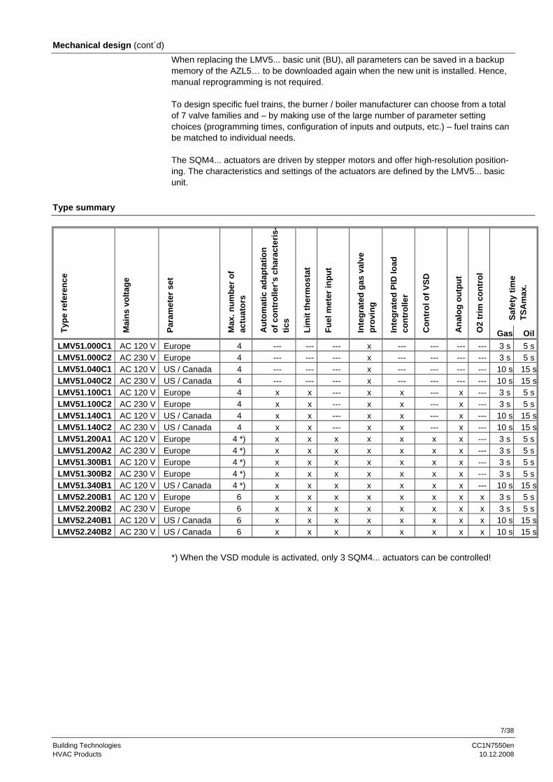
Mechanical design The following system components are integrated in the basic unit of the LMV5…: • Burner control with gas valve proving system • Electronic fuel / air ratio control for use with a maximum of 4 (LMV51…) or 6
(LMV52…) actuators • Optional PID temperature / pressure controller (load controller) • Optional variable speed drive module (VSD module)
Example: Dual-fuel burner - Gas: Modulating - Oil: 2-stage The system components (display and operating unit, actuators and O2 module) are in-terconnected via a CAN bus system. Communication between the bus users is ensured via a reliable, system-based data bus. For safety reasons, integration of the bus into external CAN bus systems is not allowed. All safety-related digital inputs and outputs of the system are constantly monitored by a contact feedback network (CFN). For flame supervision in connection with the LMV5... and continuous operation, the QRI... infrared flame detector, the QRA7... UV flame detector or an ionization probe can be used and, for intermittent operation, the optical flame detectors type QRB... or QRA2…, QRA4.U, QRA10… with AGQ1… (AC 230 V). The burner management system is operated and programmed with the help of the dis-play and operating unit (AZL5...) or a PC tool. The AZL5... features clear-text display and menu-driven operation, thus offering straightforward operation and targeted diag-nostics. To simplify diagnostics, the display shows the operating states, the type of fault and the point in time the fault occurred. The different parameter setting levels for the burner / boiler manufacturer and the heating engineer are protected by passwords. Ba-sic settings that the plant operator can make on site do not demand a password. Fur-ther, the display and operating unit serves as an interface to higher level systems such as building automation and control systems (BACS) or a PC which has the ACS450 software installed. Among other features, the unit affords convenient readout of settings and operating states, parameterization of the LMV5..., and trend logging.
7/38
Building Technologies CC1N7550en HVAC Products 10.12.2008
Mechanical design (cont´d) When replacing the LMV5... basic unit (BU), all parameters can be saved in a backup memory of the AZL5… to be downloaded again when the new unit is installed. Hence, manual reprogramming is not required. To design specific fuel trains, the burner / boiler manufacturer can choose from a total of 7 valve families and – by making use of the large number of parameter setting choices (programming times, configuration of inputs and outputs, etc.) – fuel trains can be matched to individual needs. The SQM4... actuators are driven by stepper motors and offer high-resolution position-ing. The characteristics and settings of the actuators are defined by the LMV5... basic unit.
Type summary
Safe
ty ti
me
TS
Am
ax.
Type
refe
renc
e
Mai
ns v
olta
ge
Para
met
er s
et
Max
. num
ber o
f ac
tuat
ors
Aut
omat
ic a
dapt
atio
n
of c
ontr
olle
r’s c
hara
cter
is-
tics
Lim
it th
erm
osta
t
Fuel
met
er in
put
Inte
grat
ed g
as v
alve
pr
ovin
g
Inte
grat
ed P
ID lo
ad
cont
rolle
r
Con
trol
of V
SD
Ana
log
outp
ut
O2
trim
con
trol
Gas OilLMV51.000C1 AC 120 V Europe 4 --- --- --- x --- --- --- --- 3 s 5 sLMV51.000C2 AC 230 V Europe 4 --- --- --- x --- --- --- --- 3 s 5 sLMV51.040C1 AC 120 V US / Canada 4 --- --- --- x --- --- --- --- 10 s 15 sLMV51.040C2 AC 230 V US / Canada 4 --- --- --- x --- --- --- --- 10 s 15 sLMV51.100C1 AC 120 V Europe 4 x x --- x x --- x --- 3 s 5 sLMV51.100C2 AC 230 V Europe 4 x x --- x x --- x --- 3 s 5 sLMV51.140C1 AC 120 V US / Canada 4 x x --- x x --- x --- 10 s 15 sLMV51.140C2 AC 230 V US / Canada 4 x x --- x x --- x --- 10 s 15 sLMV51.200A1 AC 120 V Europe 4 *) x x x x x x x --- 3 s 5 sLMV51.200A2 AC 230 V Europe 4 *) x x x x x x x --- 3 s 5 sLMV51.300B1 AC 120 V Europe 4 *) x x x x x x x --- 3 s 5 sLMV51.300B2 AC 230 V Europe 4 *) x x x x x x x --- 3 s 5 sLMV51.340B1 AC 120 V US / Canada 4 *) x x x x x x x --- 10 s 15 sLMV52.200B1 AC 120 V Europe 6 x x x x x x x x 3 s 5 sLMV52.200B2 AC 230 V Europe 6 x x x x x x x x 3 s 5 sLMV52.240B1 AC 120 V US / Canada 6 x x x x x x x x 10 s 15 sLMV52.240B2 AC 230 V US / Canada 6 x x x x x x x x 10 s 15 s
*) When the VSD module is activated, only 3 SQM4... actuators can be controlled!
8/38
Building Technologies CC1N7550en HVAC Products 10.12.2008
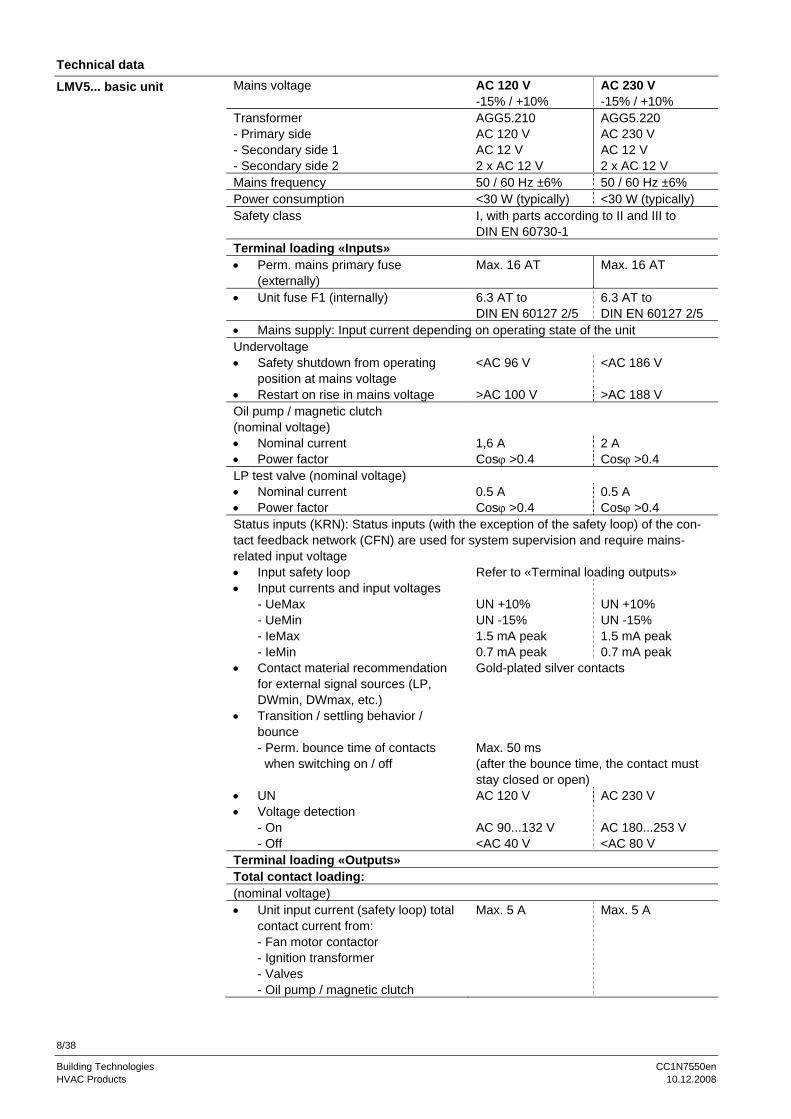
Technical data Mains voltage AC 120 V
-15% / +10% AC 230 V -15% / +10%
Transformer - Primary side - Secondary side 1 - Secondary side 2
AGG5.210 AC 120 V AC 12 V 2 x AC 12 V
AGG5.220 AC 230 V AC 12 V 2 x AC 12 V
Mains frequency 50 / 60 Hz ±6% 50 / 60 Hz ±6% Power consumption <30 W (typically) <30 W (typically) Safety class I, with parts according to II and III to
DIN EN 60730-1 Terminal loading «Inputs» • Perm. mains primary fuse
(externally) Max. 16 AT Max. 16 AT
• Unit fuse F1 (internally) 6.3 AT to DIN EN 60127 2/5
6.3 AT to DIN EN 60127 2/5
• Mains supply: Input current depending on operating state of the unit Undervoltage • Safety shutdown from operating
position at mains voltage <AC 96 V <AC 186 V
• Restart on rise in mains voltage >AC 100 V >AC 188 V Oil pump / magnetic clutch (nominal voltage) • Nominal current 1,6 A 2 A • Power factor Cosϕ >0.4 Cosϕ >0.4 LP test valve (nominal voltage) • Nominal current 0.5 A 0.5 A • Power factor Cosϕ >0.4 Cosϕ >0.4 Status inputs (KRN): Status inputs (with the exception of the safety loop) of the con-tact feedback network (CFN) are used for system supervision and require mains-related input voltage • Input safety loop Refer to «Terminal loading outputs» • Input currents and input voltages
- UeMax - UeMin - IeMax - IeMin
UN +10% UN -15% 1.5 mA peak 0.7 mA peak
UN +10% UN -15% 1.5 mA peak 0.7 mA peak
• Contact material recommendation for external signal sources (LP, DWmin, DWmax, etc.)
Gold-plated silver contacts
• Transition / settling behavior / bounce - Perm. bounce time of contacts when switching on / off
Max. 50 ms (after the bounce time, the contact must stay closed or open)
• UN AC 120 V AC 230 V • Voltage detection
- On - Off
AC 90...132 V <AC 40 V
AC 180...253 V <AC 80 V
Terminal loading «Outputs» Total contact loading: (nominal voltage) • Unit input current (safety loop) total
contact current from: - Fan motor contactor - Ignition transformer - Valves - Oil pump / magnetic clutch
Max. 5 A Max. 5 A
LMV5... basic unit
9/38
Building Technologies CC1N7550en HVAC Products 10.12.2008
Technical data (cont’d)
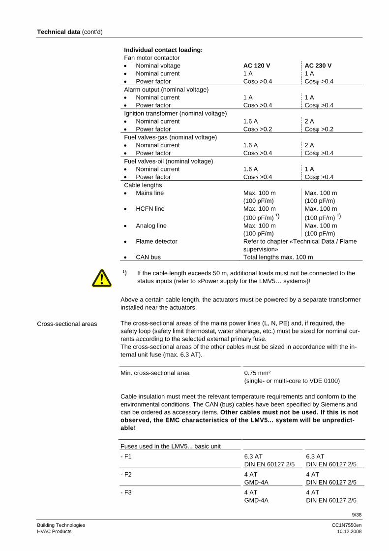
Individual contact loading: Fan motor contactor • Nominal voltage AC 120 V AC 230 V • Nominal current 1 A 1 A • Power factor Cosϕ >0.4 Cosϕ >0.4 Alarm output (nominal voltage) • Nominal current 1 A 1 A • Power factor Cosϕ >0.4 Cosϕ >0.4 Ignition transformer (nominal voltage) • Nominal current 1.6 A 2 A • Power factor Cosϕ >0.2 Cosϕ >0.2 Fuel valves-gas (nominal voltage) • Nominal current 1.6 A 2 A • Power factor Cosϕ >0.4 Cosϕ >0.4 Fuel valves-oil (nominal voltage) • Nominal current 1.6 A 1 A • Power factor Cosϕ >0.4 Cosϕ >0.4 Cable lengths • Mains line Max. 100 m
(100 pF/m) Max. 100 m (100 pF/m)
• HCFN line Max. 100 m (100 pF/m) ¹)
Max. 100 m (100 pF/m) ¹)
• Analog line Max. 100 m (100 pF/m)
Max. 100 m (100 pF/m)
• Flame detector Refer to chapter «Technical Data / Flame supervision»
• CAN bus Total lengths max. 100 m
¹) If the cable length exceeds 50 m, additional loads must not be connected to the status inputs (refer to «Power supply for the LMV5… system»)!
Above a certain cable length, the actuators must be powered by a separate transformer installed near the actuators. The cross-sectional areas of the mains power lines (L, N, PE) and, if required, the safety loop (safety limit thermostat, water shortage, etc.) must be sized for nominal cur-rents according to the selected external primary fuse. The cross-sectional areas of the other cables must be sized in accordance with the in-ternal unit fuse (max. 6.3 AT).
Min. cross-sectional area 0.75 mm² (single- or multi-core to VDE 0100)
Cable insulation must meet the relevant temperature requirements and conform to the environmental conditions. The CAN (bus) cables have been specified by Siemens and can be ordered as accessory items. Other cables must not be used. If this is not observed, the EMC characteristics of the LMV5... system will be unpredict-able! Fuses used in the LMV5... basic unit - F1 6.3 AT
DIN EN 60127 2/5 6.3 AT DIN EN 60127 2/5
- F2 4 AT GMD-4A
4 AT DIN EN 60127 2/5
- F3 4 AT GMD-4A
4 AT DIN EN 60127 2/5
Cross-sectional areas
10/38
Building Technologies CC1N7550en HVAC Products 10.12.2008
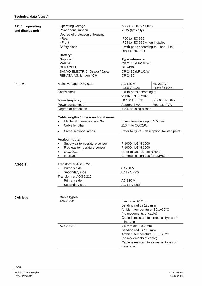
Technical data (cont’d)
Operating voltage AC 24 V -15% / +10% Power consumption <5 W (typically) Degree of protection of housing - Rear - Front
IP00 to IEC 529 IP54 to IEC 529 when installed
Safety class I, with parts according to II and III to DIN EN 60730-1
Battery: Supplier Type reference VARTA CR 2430 (LF-1/2 W) DURACELL DL 2430 SANYO ELECTRIC, Osaka / Japan CR 2430 (LF-1/2 W) RENATA AG, Itingen / CH CR 2430
Mains voltage «X89-01» AC 120 V
–15% / +10% AC 230 V –15% / +10%
Safety class I, with parts according to II to DIN EN 60730-1
Mains frequency 50 / 60 Hz ±6% 50 / 60 Hz ±6% Power consumption Approx. 4 VA Approx. 4 VA Degree of protection IP54, housing closed Cable lengths / cross-sectional areas: • Electrical connection «X89» Screw terminals up to 2.5 mm² • Cable lengths ≤10 m to QGO20...
• Cross-sectional areas Refer to QGO... description, twisted pairs Analog inputs: • Supply air temperature sensor Pt1000 / LG-Ni1000 • Flue gas temperature sensor Pt1000 / LG-Ni1000 • QGO20... Refer to Data Sheet N7842 • Interface Communication bus for LMV52... Transformer AGG5.220 - Primary side - Secondary side
AC 230 V AC 12 V (3x)
Transformer AGG5.210 - Primary side - Secondary side
AC 120 V AC 12 V (3x)
Cable types: AGG5.641 8 mm dia. ±0.2 mm
Bending radius 120 mm Ambient temperature -30...+70°C (no movements of cable) Cable is resistant to almost all types of mineral oil
AGG5.631 7.5 mm dia. ±0.2 mm Bending radius 113 mm Ambient temperature -30...+70°C (no movements of cable) Cable is resistant to almost all types of mineral oil
AZL5... operating and display unit
PLL52...
AGG5.2…
CAN bus

11/38
Building Technologies CC1N7550en HVAC Products 10.12.2008
Technical data (cont’d) Note: All measured voltages refer to connection terminal N (X10–02, terminal 4).
Supply voltage operation / test at termi-nal POWER QRI... (X10–02, terminal 2)
Approx. DC 14 / 21 V
Minimum signal voltage required at ter-minal FSV / QRI... (X10–02, terminal 6)
Min. DC 3,5 V Display flame approx. 50 %
7719a01E/0502
SIEMENS
QRIMade in Germany
Landis & Staefa blue
brown
0...10 VRi > 10 MΩ
X10-02 / 6
X10-02 / 4
X10-02 / 2
LMV...
+
black
For detailed information, refer to Data Sheet N7719.
No-load voltage at terminal ION (X10–03, terminal 1)
Approx. UMains
Note: The ionization probe must be installed such that protection against electrical shock hazard is ensured!
Short-circuit current Max. AC 0,5 mA Required detector current Min. DC 6 µA
Display flame approx. 50 % Possible detector current Max. DC 85 µA
Display flame approx. 100 % Permissible length of detector cable (lay separately)
100 m (wire-earth 100 pF/m)
The greater the detector cable capacitance (cable length), the lower the voltage at the ionizations probe and, therefore, the lower the detector current. In the case of extensive cable lengths and high-resistance flames, it may be necessary to use low-capacitance cables (e.g. ignition cable). The electronic circuit is designed such that impacts of the ignition spark on the ionization current will be largely eliminated. Nevertheless, it must be ensured that the minimum detector current required will already be reached during the ignition phase. If that is not the case, the connections of the ignition transformer on the primary side must be changed and / or the location of the electrodes also.
Flame supervision
QRI (suited for continuous operation)
Connection diagram
IONIZATION (suited for continuous operation)
Note
12/38
Building Technologies CC1N7550en HVAC Products 10.12.2008
Technical data (cont’d) For intermittent operation only. AGQ1… is only available for AC 230 V mains voltage. Power supply in operation DC 280…325 V Power supply in test mode DC 390…750 V For more detailed information about QRA2… / QRA10…, refer to Data Sheet N7712. For more detailed information about QRA4.U, refer to Data Sheet N7711.
QRA2… (QRA4.U / QRA10... must not be used when extraneous light suppression is activated since detector tests will not be made in that case!
Possible ionization current Max. 10 µA Ionization current required Min. 6 µA In connection with the LMV5…, ancillary unit AGQ1…A27 must be used. Power supply AC 230 V Possible current Max. 500 µA Current required Min. 200 µA
7550
a20/
0308
br bl rt sw AGQ1...A27sw bl
QR
A
X10
-02
/ 3
X10
-02
/ 4
X3-
01 /
1
X10
-03
/ 1
LMV5...
Assignment of LMV5…terminals: X10-02 / 3 L X10-02 / 4 N X10-03 / 1 Ionization X3-01 / 1 Fan
When laid together with other cables (e.g. in a cable duct), the length of the 2-core ca-ble between QRA… and AGQ… must not exceed 20 m. A maximum cable length of 100 m is permitted if the 2-core cable is run at a distance of at least 5 cm from other live cables. The length of the 4-core cable between AGQ… and LMV5… is limited to 20 m. A maximum cable length of 100 m is permitted if the signal line (ionization / black) is not run in the same cable but separately at a distance of at least 5 cm from other live cables.
Flame supervision
QRA2… / QRA4.U / QRA10… with AGQ1…A27
Note
QRA…
LMV5…
AGQ1…A27
Connection diagram

13/38
Building Technologies CC1N7550en HVAC Products 10.12.2008
Technical data (cont’d) Power supply for operation - QRA73A17 / QRA75A17 - QRA73A27 / QRA75A27
AC 120 V AC 230 V
Power supply for test via increasing the power supply for QRI... (X10-02 terminal 2)
From DC 14 V up to DC 21 V
Required signal voltage (X10-02 terminal 6)
Min. DC 3.5 V
Perm. length of detector cable - 6 wire cable - Signal cable no. 3, 4 and 5
Max. 10 Max. 100 m (lay separately from L, N and PE in shielded cable)
QRA7... For more detailed information about QRA7…, refer to Data Sheet N7712.
7550a22/0108
LMV5...
X10-02.6
X10-02.2
X10-02.5
X10-02.4
X10-02.3
QRA7...
0...10 V
+
Ri > 10 MΩ
4
3
PE
21
5
Assignment of LMV5… terminals: X10-02 / 2 QRI... supply X10-02 / 3 L X10-02 / 4 N X10-02 / 5 PE X10-02 / 6 QRI... signal
Flame supervision
QRA7… (suited for continuous operation)
Connection diagram

14/38
Building Technologies CC1N7550en HVAC Products 10.12.2008
Technical data (cont’d) No-load voltage at the QRB... terminal (X10–02, terminal 1)
Approx. DC 8 V
Detector current required (with flame) Min. DC 30 µA Display flame 35 %
Permissible detector current (dark current with no flame)
Max. DC 5 µA
Permissible detector current Max. DC 70 µA Display flame approx. 100 %
Permissible length of QRB... detector ca-ble (lay separately)
100 m (wire-wire 100 pF/m)
A detector resistance value of RF <5 kΩ is identified as a short-circuit and, in operation, will lead to safety shutdown as if loss of flame had occurred. Measurement of the volt-age at terminal QRB... during burner operation gives a clear indication: If voltage drops below 1 V, safety shutdown will probably occur. For that reason, before using a highly sensitive photoresistive flame detector (QRB1B, QRB3S), it should be checked whether such a detector is really required! Increasing line capacitance between the QRB... ter-minal and mains live «L» adversely affects the sensitivity and increases the risk of damaged flame detectors due to mains overvoltages. Separate routing of detector ca-bles as specified in Data Sheet 7714 must be observed. Configuration extraneous light In the case of incinerator plant or other types of plant operating at combustion chamber temperatures of >650 °C, an extraneous light test must not be made .
Observe the relevant standards and regulations (e.g. extra supervision of the combustion chamber temperature)!
For indication of flame (on the AZL5...), observe the following general rules: The above percentage values are obtained when, for parameter «Standardize» (stan-dardization of flame signal), the default setting is used. The accuracy of the display is a maximum of ±10 %, depending on the tolerances of the components. It should also be noted that, for physical reasons, there is no linear relationship between the display and the detector signal values. This is especially obvious with ionization current supervision. For more detailed information, refer to Data Sheet N7714.
QRB… must not be used when extraneous light suppression is acti-vated since detector tests will not be made in that case!
Flame supervision
QRB... (for intermittent operation only)
Notes
Indication of flame AZL5…
15/38
Building Technologies CC1N7550en HVAC Products 10.12.2008
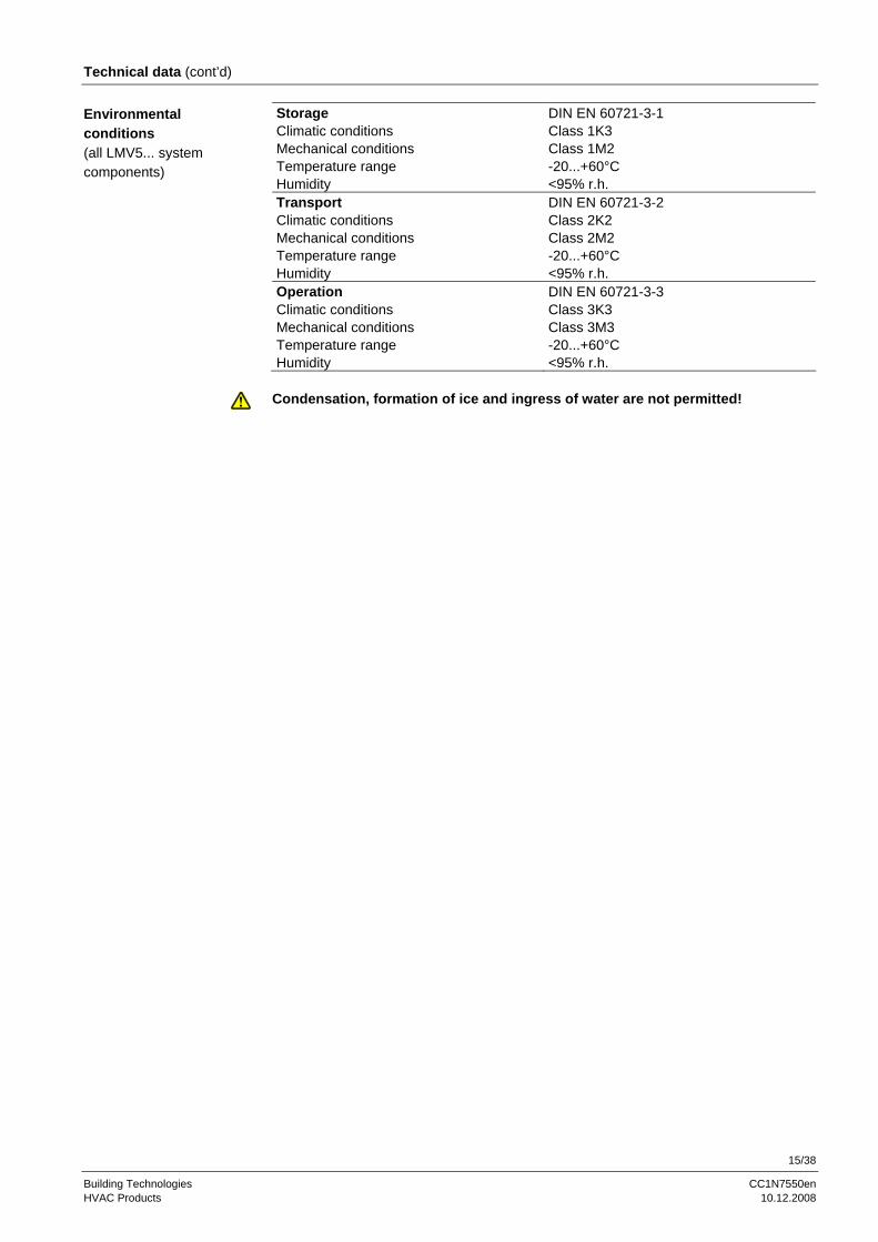
Technical data (cont’d) Storage DIN EN 60721-3-1 Climatic conditions Class 1K3 Mechanical conditions Class 1M2 Temperature range -20...+60°C Humidity <95% r.h. Transport DIN EN 60721-3-2 Climatic conditions Class 2K2 Mechanical conditions Class 2M2 Temperature range -20...+60°C Humidity <95% r.h. Operation DIN EN 60721-3-3 Climatic conditions Class 3K3 Mechanical conditions Class 3M3 Temperature range -20...+60°C Humidity <95% r.h.
Condensation, formation of ice and ingress of water are not permitted!
Environmental conditions (all LMV5... system components)
16/38
Building Technologies CC1N7550en HVAC Products 10.12.2008
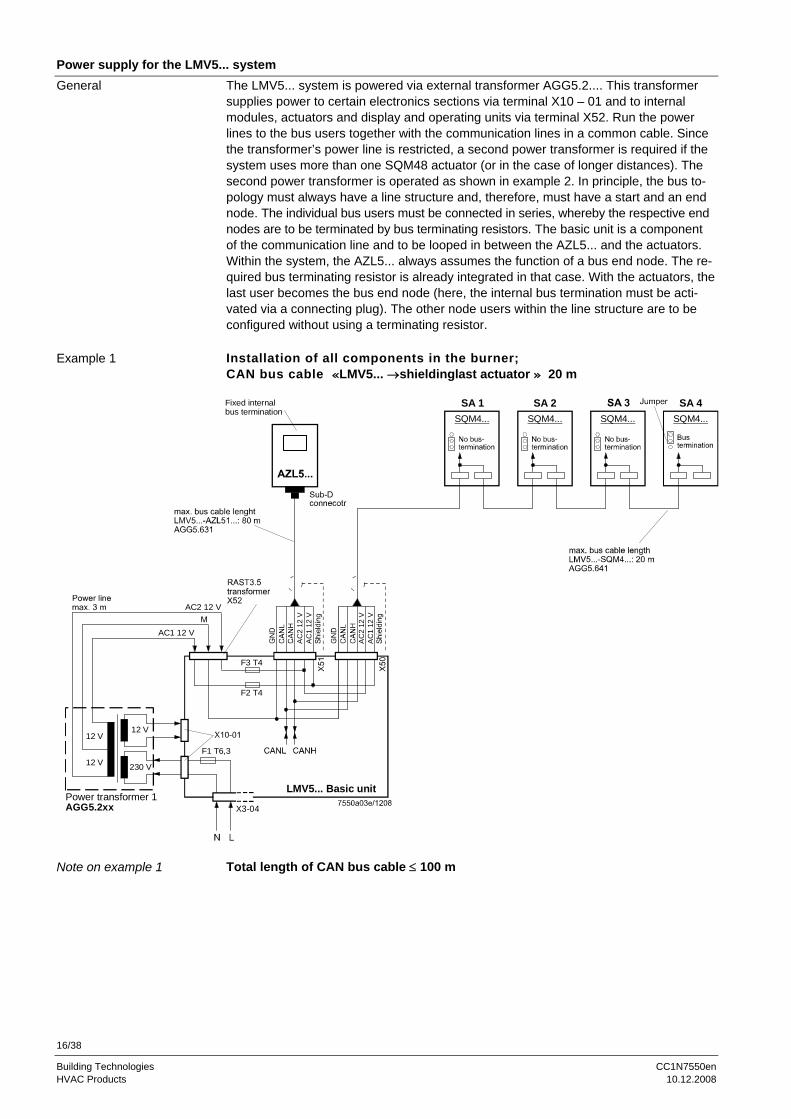
Power supply for the LMV5... system The LMV5... system is powered via external transformer AGG5.2.... This transformer supplies power to certain electronics sections via terminal X10 – 01 and to internal modules, actuators and display and operating units via terminal X52. Run the power lines to the bus users together with the communication lines in a common cable. Since the transformer’s power line is restricted, a second power transformer is required if the system uses more than one SQM48 actuator (or in the case of longer distances). The second power transformer is operated as shown in example 2. In principle, the bus to-pology must always have a line structure and, therefore, must have a start and an end node. The individual bus users must be connected in series, whereby the respective end nodes are to be terminated by bus terminating resistors. The basic unit is a component of the communication line and to be looped in between the AZL5... and the actuators. Within the system, the AZL5... always assumes the function of a bus end node. The re-quired bus terminating resistor is already integrated in that case. With the actuators, the last user becomes the bus end node (here, the internal bus termination must be acti-vated via a connecting plug). The other node users within the line structure are to be configured without using a terminating resistor. Installation of all components in the burner; CAN bus cable «LMV5... →shieldinglast actuator » 20 m
Power transformer 1AGG5.2xx
12 V
AC1 12 V
F1 T6,3
F3 T4
AC
1 12
VA
C2
12 V
12 V 230 V
12 V
AC2 12 V
X3-04
Fixed internalbus termination
SA 4SQM4...SQM4...
SA 2SQM4...
SA 1SQM4...
AC
1 12
VA
C2
12 V
F2 T4
LMV5... Basic unit
Total length of CAN bus cable ≤ 100 m
General
Example 1
Note on example 1

17/38
Building Technologies CC1N7550en HVAC Products 10.12.2008
Power supply for LMV5... system (cont´d) Basic unit LMV5... in the control panel, actuator on the burner; CAN bus cable «LMV5... ↔ last actuator» >20 m
max. bus cable lengthSA4 - SA1: 20 mAGG5.641
max. bus cable lengthLMV5...- SA1: 75 mAGG5.641 orAGG5.631
max. cable lengthfrom power supplyof actuators 3 m
F T4
AC1
12 V
X50
Power transformer 1AGG5.2xx
12 V
AC1 12 V
LMV5... basic unit
F1 T6.3
X10-01
F3 T4
X51
max. bus cable lengthLMV5...-AZL51...: 5 mAGG5.631
Control cabinet
GN
D
12 V 230 V
12 V
SA 4SQM4...SQM4...SQM4...SQM4...
230 V 12 V
F T2
N
F T4
AC2
12 V
AC2 12 V
M
AC1
12 V
AC2
12 V
GN
D
Sub-Dconnector
F2 T4
Powertransformer 2AGG5.2xx
Burner
Total CAN bus cable length ≤ 100 m If the distance between the LMV5... and the last actuator exceeds 20 m, or if more than one SQM48… are fitted to the burner (refer to «Determination of the maximum cable length»), a second transformer is required for powering the actuators. In that case, transformer 1 powers the LMV5... basic unit and the AZL5... display and operating unit (control panel). Transformer 2 powers the actuators (burner).
With the CAN bus cable connections from the LMV5... (control panel) to the first actuator (burner), the 2 voltages AC1 and AC2 on the LMV5... side must not be connected and only cables CANH, CANL and M (+shielding) are to be connected to the first actuator (burner).
In that case, the actuators must be powered by a second transformer which to be lo-cated near the actuators. The power from that transformer (lines AC1, AC2, M) must be fed to the actuator (ACT4 in the example above) and then connected through via bus cable AGG5.641 (cable type 1) to all the other actuators. The fuses required for trans-former 1 are accommodated in the LMV5... basic unit.
For transformer 2, the 3 fuses must be located close to the transformer (for type, refer to Basic Documentation P7550).
For additional examples, refer to Basic Documentation P7550!
Example 2
Notes on example 2
18/38
Building Technologies CC1N7550en HVAC Products 10.12.2008
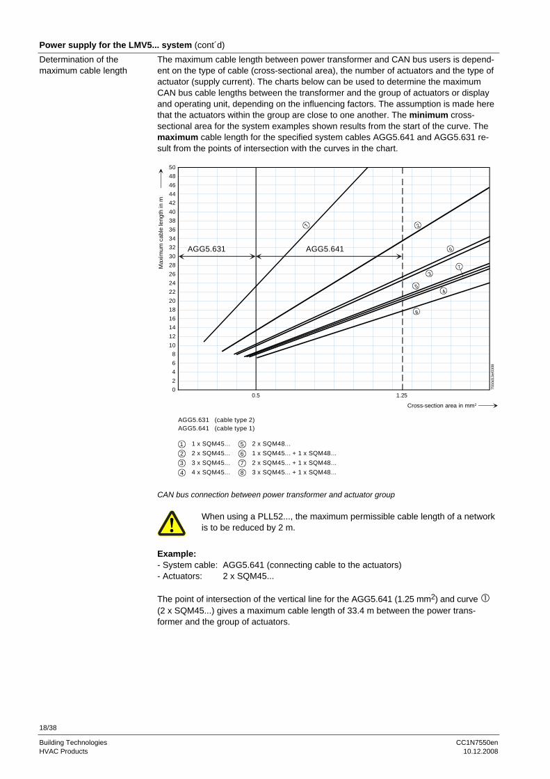
Power supply for the LMV5... system (cont´d) The maximum cable length between power transformer and CAN bus users is depend-ent on the type of cable (cross-sectional area), the number of actuators and the type of actuator (supply current). The charts below can be used to determine the maximum CAN bus cable lengths between the transformer and the group of actuators or display and operating unit, depending on the influencing factors. The assumption is made here that the actuators within the group are close to one another. The minimum cross-sectional area for the system examples shown results from the start of the curve. The maximum cable length for the specified system cables AGG5.641 and AGG5.631 re-sult from the points of intersection with the curves in the chart.
504846444240383634323028262422201816141210
86420
0.5 1.25
2
3
5
7
8
AGG5.631 AGG5.641
4
6
AGG5.631 (cable type 2)AGG5.641 (cable type 1)
1 1 x SQM45...2 2 x SQM45...3 3 x SQM45...4 4 x SQM45...
5 2 x SQM48...
7 2 x SQM45... + 1 x SQM48...8 3 x SQM45... + 1 x SQM48...
6 1 x SQM45... + 1 x SQM48...
Cross-section area in mm2
Max
imum
cab
le le
ngth
in m
7550
d13e
/030
8
CAN bus connection between power transformer and actuator group
When using a PLL52..., the maximum permissible cable length of a network is to be reduced by 2 m.
Example: - System cable: AGG5.641 (connecting cable to the actuators) - Actuators: 2 x SQM45... The point of intersection of the vertical line for the AGG5.641 (1.25 mm2) and curve (2 x SQM45...) gives a maximum cable length of 33.4 m between the power trans-former and the group of actuators.
Determination of the maximum cable length
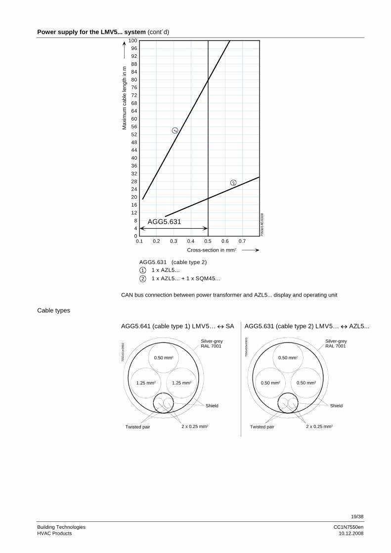
19/38
Building Technologies CC1N7550en HVAC Products 10.12.2008
Power supply for the LMV5... system (cont´d) 100
96928884807672686460565248444036322824201612
8400.1 0.2 0.3 0.4 0.5 0.6 0.7
Cross-section in mm2
Max
imum
cab
le le
ngth
in m
7550
d14E
/030
8
AGG5.631
1
AGG5.631 (cable type 2)1 1 x AZL5...
2
2 1 x AZL5... + 1 x SQM45... CAN bus connection between power transformer and AZL5... display and operating unit AGG5.641 (cable type 1) LMV5... ↔ SA
1.25 mm2
2 x 0.25 mm2
1.25 mm2
Twisted pair
0.50 mm2
Shield
Silver-greyRAL 7001
7550
z01e
/090
3
AGG5.631 (cable type 2) LMV5... ↔ AZL5...
0.50 mm2
2 x 0.25 mm2
0.50 mm2
Twisted pair
0.50 mm2
Shield
Silver-greyRAL 7001
7550
z02e
/090
3
Cable types
20/38
Building Technologies CC1N7550en HVAC Products 10.12.2008
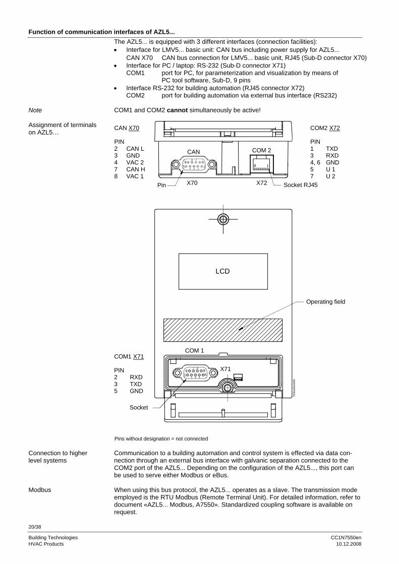
Function of communication interfaces of AZL5... The AZL5... is equipped with 3 different interfaces (connection facilities): • Interface for LMV5... basic unit: CAN bus including power supply for AZL5...
CAN X70 CAN bus connection for LMV5... basic unit, RJ45 (Sub-D connector X70) • Interface for PC / laptop: RS-232 (Sub-D connector X71)
COM1 port for PC, for parameterization and visualization by means of PC tool software, Sub-D, 9 pins
• Interface RS-232 for building automation (RJ45 connector X72) COM2 port for building automation via external bus interface (RS232)
COM1 and COM2 cannot simultaneously be active! CAN X70
PIN 2 CAN L3 GND4 VAC 27 CAN H8 VAC 1
Pins without designation = not connected
CAN
Pin
COM 2
LCD
X70 X72
COM2 X72
PIN 1 TXD3 RXD4, 6 GND5 U 17 U 2
8 19 6
5 1
8 7
4 3 2
Socket RJ45
Operating field
Socket
COM1 X71
PIN 2 RXD3 TXD5 GND
COM 1
X71961 5
7 8
2 3 4
7550
a08e
/090
6
Communication to a building automation and control system is effected via data con-nection through an external bus interface with galvanic separation connected to the COM2 port of the AZL5... Depending on the configuration of the AZL5..., this port can be used to serve either Modbus or eBus. When using this bus protocol, the AZL5... operates as a slave. The transmission mode employed is the RTU Modbus (Remote Terminal Unit). For detailed information, refer to document «AZL5... Modbus, A7550». Standardized coupling software is available on request.
Note
Assignment of terminals on AZL5…
Connection to higher level systems
Modbus

21/38
Building Technologies CC1N7550en HVAC Products 10.12.2008
Function of VSD (only for use with LMV52.2... and AZL52.XXB) The VSD module is an extension to the LMV52.2... and is used for the control of a VSD that ensures safety-related supervision of the fan speed. 2 fuel meters (oil and gas) can be connected as an option. A VSD can be connected to the VSD module integrated in the LMV52.2… The VSD is controlled via an analog current output and a potential-free release contact. Evaluation of the alarm feedback signal from the VSD is accomplished with a 0…24 V input. When activated, the LMV52.2... will enter the safety phase. Both motor speed and direction of rotation are acquired by an inductive sensor. In addition, the asymmetric speed signal is checked for direction of rotation and plausibility. The VSD module generates the acceleration / deceleration ramps in accordance with the parameter settings made on the LMV52.2... The motor speed is adjusted the same way the speed of the actuators is adjusted. For this reason, the characteristic of the VSD must be linear. Remove filters, delay and damping elements. The VSD module of the LMV52.2... ensures that the motor’s speed is controlled to the setpoint. The control range is limited to +15% / -10%. If control range limitation becomes active, the AZL5... will display it. If this is the case for a longer period of time (→ «Safety time ratio con-trol»), the LMV52.2... will shut down, delivering the message «Special position not reached» or «Speed not reached». Speed control is only active with speeds ≥8%.
M
ACT gas ACT air
MACT oil
SensorL
Sensor diskLMV5x.2...
Gas
Oil
7550b12e/0704
Meter
Meter
M M
Actual speed
X73X71
X72
X70
Release
Required speed 0/4...20 mA
Alarm 0...24 VVSD
The auxiliary actuator can be parameterized on the basic unit, depending on the type of fuel. The motor’s speed can be acquired with different types of sensors. To detect the mo-tor‘s direction of rotation with a sensor, a sensor disk with angular steps of 60°, 120° and 180° is used. The sensor disk generates pulse intervals of 3 different lengths.
Speed acquisition is safety-related!
We recommend using the AGG5.310 accessory kit. To enable the acquired speed to be standardized to the range of 0...100%, the speed corresponding to 100% must be parameterized (→ «Standardization of speed»).
For more detailed information about the AGG5.310, refer to Basic Documentation P7550
or Mounting Instructions M7550!
General
Basic diagram
Speed feedback signal

22/38
Building Technologies CC1N7550en HVAC Products 10.12.2008
Function of VSD (cont´d) To acquire the amount of fuel consumed, up to 2 fuel meters can be connected. As-signment to the type of fuel is fixed. To adapt the system to different types of fuel me-ters, assignment of the number of pulses and the resulting fuel throughput must be pa-rameterized. Type of sensor: Inductive sensor to DIN 19234 (Namur) or open collector (pnp) with UCE-sat <4 V, UCEmin >DC 15 V or Reed contact Frequency: ≤ 300 Hz Pulses / l or gal, m3: ≤ 9999.9999 (to be parameterized) Pulses / ft3: ≤ 999.99999 (to be parameterized) Power supply: DC 10 V, max. 15 mA Switching current: >10 mA The VSD is controlled via a current interface, which can be switched between 0...20 mA and 4...20 mA. If the VSD requires a DC 0...10 V input signal, a resistor of 500 Ω ±1% must be con-nected to its input in parallel. LMV5... system → VSD Both functional tests with the LMV5... system were conducted and successfully com-pleted with the following types of VSDs: Siemens: - Micromaster 440 Danfoss: - VT2807 In operation, VSDs produce electromagnetic interference. For this reason – to ensure EMC of the entire system – the instructions given by the manufacturers must be observed: Siemens: - Operating Instructions
→ EMC-compatible installation Danfoss: - Technical Brochure → Radio Interference Suppression Filters
- Data Sheet of Danfoss EMC filter for long motor cables
When using other types of VSDs, compliance with EMC regulations and correct functioning will not be ensured!
Fuel meter
Fuel meter input X71 / X72
Configuration of interface
Note
Functional tests
EMC

23/38
Building Technologies CC1N7550en HVAC Products 10.12.2008
Function of LMV52... with O2 trim control The LMV52... system is an extended LMV51... system. A special feature of the LMV52… is control of the residual oxygen content, aimed at increasing boiler efficiency. In addition to the features of the LMV51..., the LMV52... provides O2 trim control, con-trol of a maximum of 6 actuators, control of a VSD, and acquisition of cumulated fuel consumption and current fuel throughput. The LMV52... system uses an O2 sensor (QGO20...), an external O2 module, and the standard components of the LMV51... sys-tem. The PLL... O2 module is a detached measuring module for use with the QGO20... sen-sor with a connection facility for 2 temperature sensors (Pt1000 / LG-Ni 1000). With the help of the temperature sensors (flue gas and combustion air temperature), the com-bustion performance can be determined, depending on the type of fuel. The module communicates via CAN bus with the LMV52... basic unit. The O2 module is to be lo-cated near the QGO... (<10 m) to keep the impact on sensitive sensor lines as low as possible. To power the sensor’s heating element, the O2 module needs its own mains connection. The fuel meters must be connected directly to the fuel-related inputs of the basic unit. On the AZL5... display and operating unit, the individual consumption values can be read out and the meter readings reset.
General

24/38
Building Technologies CC1N7550en HVAC Products 10.12.2008
Function of LMV52... with O2 trim control (cont’d) The O2 trim controller or O2 monitor can be deactivated or activated in various operat-ing modes by setting a parameter.
The ratio curves must always be adjusted such that there are sufficient amounts of excess O2 available, irrespective of environmental condi-tions!
Parameter: O2 Ctrl/Guard (man deact / O2-guard/ O2-control /
conAutoDeac / auto deact) man deact Both O2 trim controller and O2 monitor are deactivated. The system
operates along the parameterized ratio curves. O2-guard Only the O2 monitor is active. Prior to startup, the O2 sensor must
have reached its operating temperature. If not, startup will be pre-vented. If the O2 monitor responds, or if an error occurs in connection with O2 measurement, the O2 module or O2 sensor, safety shutdown will take place, followed by a repetition if possible, otherwise lockout.
O2-control Both the O2 trim controller and the O2 monitor are active. Prior to
startup, the O2 sensor must have reached its operating temperature. If not, startup will be prevented. If the O2 monitor responds, or if an error occurs in connection with O2 measurement, the O2 module or O2 sensor, safety shutdown will take place, followed by a repetition if possible, otherwise lockout.
conAutoDeac
Both the O2 trim controller and the O2 monitor are active (option «automatic deactivation»). Startup takes place before the O2 sensor has reached its operating temperature. O2 trim control in operation is activated only when the operating temperature is reached and the sensor test has been successfully completed. If the O2 monitor re-sponds, or if an error occurs in connection with O2 measurement, the O2 module, the O2 sensor or the sensor test, both the O2 trim con-troller and the O2 monitor will automatically be deactivated. The system operates along the parameterized ratio curves and this parameter will be set to auto deact. The AZL5... indicates automatic deactivation. The error code is maintained until O2 trim control is manually deactivated or activated.
auto deact O2 trim control has automatically been deactivated and the system
operates along the parameterized ratio curves (do not select this sys-tem parameter). To deactivate the O2 trim controller / O2 monitor, use parameter setting «man deact».
Warning when flue gas temperature exceeds a certain level. If a flue gas temperature sensor is connected and activated, a warning signal will be delivered when a preset flue gas temperature is exceeded. High flue gas temperatures are an indication of higher boiler losses ⇒ Boiler should be cleaned. The warning threshold can be set separately for firing on gas and oil.
O2 trim control O2 trim controller / O2 monitor
Auxiliary function

25/38
Building Technologies CC1N7550en HVAC Products 10.12.2008
Block diagram inputs / outputs
X3-04.3
X3-04.5 Power supply live conductor (L)
X3-04.4 Power supply neutral conductor (N)
Protective earth (PE)
X3-04.2 Power signal for safety loop
X3-04.1 Safety loop
X3-03.2 Power signal for end switch burner flange
X3-03.1 End switch burner flange(part of safety loop)
X3-01.2 Alarm
X3-01.1 Fan motor contactor
IgnitionX4-02.3
Start signal or PS relief (APS test valve)X4-03.3
Oil pump / magnetic clutchX6-02.3
Fuel valve SV (OIL)X6-03.3
Fuel valve V2 (OIL)X7-01.3
Fuel valve V3 (OIL)X7-02.3
Fuel valve V1 (OIL)X8-02.1
Auxiliary terminal for valves connected in seriesX8-02.2
Fuel valve V1 (OIL)X8-03.1
Auxiliary terminal for valves connected in seriesX8-03.2
Signal lamp oilX8-01.2
Signal lamp gasX8-01.1
X4-02.2
X4-03.2
X6-02.2
X6-03.2
X7-01.2
X7-02.2
X8-02.3
X8-03.3
M
P
SLT AUX WATER-SHORTAGE
L1-L3
FAN
PE
N
L1F 6.3 AT
L1'
OIL
OIL + GAS
OIL + GAS
LMV5...LMV5...
3
7550
a10e
/090
3

26/38
Building Technologies CC1N7550en HVAC Products 10.12.2008
Block diagram inputs / outputs (cont´d)
1
T1AGG5.2xx
ON/OFF
L1'
QRB...
Black
FLAME alternative 2
FLAME alternative 3
FLAME alternative 1
PE
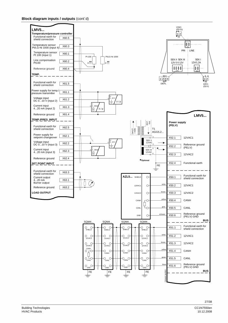
27/38
Building Technologies CC1N7550en HVAC Products 10.12.2008
Block diagram inputs / outputs (cont´d)
X60.5Functional earth forshield connection
X60.2
X60.4
Line compensation Pt100
Reference ground
X60.3
X60.1
Temperature sensorPt/LG-Ni 1000 (input 4)
Temperature sensorPt 100 (input 1)
Pt 100 Pt/LG-Ni 1000
TEMP.
X61.5Functional earth forshield connection
X61.3
X61.4
Current input4...20 mA (input 2)
Reference ground
X61.1
X61.2
Power supply for temp./pressure transmitter
Voltage inputDC 0...10 V (input 2)
TEMP./PRES. INPUT
ϑ
4...20mA
0...10 VU
I
X62.5Functional earth forshield connection
X62.3
X62.4
Current input4...20 mA (input 3)
Reference ground
X62.1
X62.2
Power supply forsetpoint changeover
Voltage inputDC 0...10 V (input 3)
SET POINT INPUT
4...20mA
0...10 VU
I
+
+
+
+
X63.1
X63.2
Current output4...20 mABurner output
Reference ground
X63.3Functional earth forshield connection
LOAD OUTPUT
X50.1 Functional earth forshield connection
X50.4
X50.5
Reference ground(PELV) GND
X50.2
X50.3
X50.6
12VAC1
12VAC2
CANH
CANL
BUS
X52.2
X52.3
X52.4
X52.1 12VAC1
Reference ground(PELV)
12VAC2
Functional earth
X51.1 Functional earth forshield connection
X51.4
X51.5
Reference ground(PELV) GND
X51.2
X51.3
X51.6
12VAC1
12VAC2
CANH
CANL
BUS
12VAC1
12VAC2
CANH
CANL
GND
SHIELD
12VAC1
12VAC2
CANH
CANL
GND
SHIELD
12VAC1
12VAC2
CANH
CANL
GND
SHIELD
12VAC1
12VAC2
CANH
CANL
GND
SHIELD
12VAC1
12VAC2
CANH
CANL
GND
SHIELDAZL5...
FEFEFEFE
SQM4...SQM4...SQM4...SQM4...
brown
white
yellow
green
black
brown
white
yellow
grün
schwarz
Temperature/pressure controller
Power supply(PELV)
LMV5...
LMV5...
ϑ
ϑ / p
ϑ / p
PR
ILIN
E
SEK
I12VA
C
SEK II12VAC
SEK III12VAC
FE
1
2
3
4
T1AGG5.2...
7550
a10.
3e/0
903
*
*Optional
12V 0 0 12V
DEFL
1 2 43
21
CDO(02-D)
DFO(02-I)
LINE
12V/1,2A
1 2
SEK II SEK III SEK I
PRI
28/38
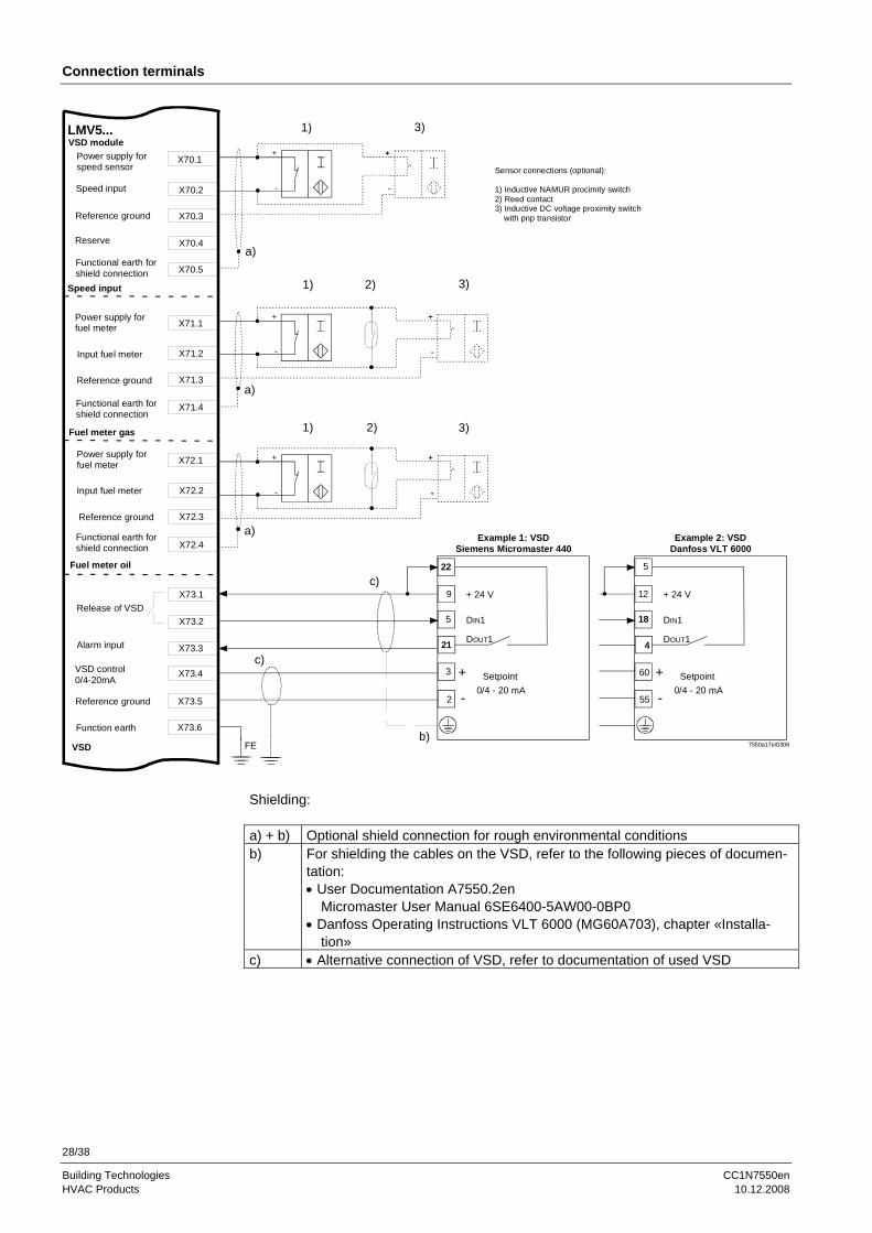
Building Technologies CC1N7550en HVAC Products 10.12.2008
Connection terminals
Functional earth for shield connection
X70.4
X70.5
Reserve
Reference ground
X70.2
X70.3
Speed input
Speed input
X71.1
Functional earth for shield connection
X71.4
Reference ground
X71.2
X71.3
Power supply for fuel meter
Input fuel meter
Fuel meter gas
X72.1
Functional earth for shield connection X72.4
X72.2
X72.3
X73.2
X73.3
VSD control0/4-20mA
Reference ground
X73.1
Function earth
VSD
VSD moduleLMV5...
X70.1Power supply forspeed sensor
Reference ground
Power supply for fuel meter
Input fuel meter
Fuel meter oil
X73.5
X73.6
X73.4
Alarm input
Release of VSD
FE
+
-
+
-
+
-
1)
2) 3)1)
1) 3)
3)
2)
Sensor connections (optional):
1) Inductive NAMUR procimity switch2) Reed contact3) Inductive DC voltage proximity switch with pnp transistor
2
3
21
5
9
Example 1: VSDSiemens Micromaster 440
+ 24 V
DIN1
Setpoint
DOUT1
+
- 0/4 - 20 mA
22
a)
a)
a)
b)
55
60
4
5
12
Example 2: VSDDanfoss VLT 6000
+ 24 V
DIN1
Setpoint
DOUT1
+
-
7550a17e/0308
0/4 - 20 mA
18
c)
c)
Shielding: a) + b) Optional shield connection for rough environmental conditions b) For shielding the cables on the VSD, refer to the following pieces of documen-
tation: • User Documentation A7550.2en
Micromaster User Manual 6SE6400-5AW00-0BP0 • Danfoss Operating Instructions VLT 6000 (MG60A703), chapter «Installa-
tion» c) • Alternative connection of VSD, refer to documentation of used VSD
29/38
Building Technologies CC1N7550en HVAC Products 10.12.2008
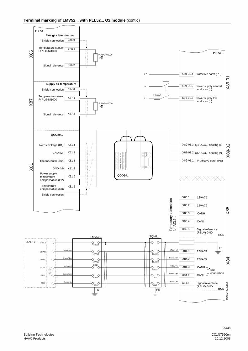
Terminal marking of LMV52... with PLL52... O2 module (cont’d)
X86.3Shield connection
X86.2Signal reference
X86.1Temperature sensorPt / LG-Ni1000
Pt / LG-Ni1000q
Shield connection
X81.3
X81.4
X81.1
X81.2
Nernst voltage (B1)
GND (M)
X81.6
X81.5
QGO20...
X85.3
X85.4
Signal reference(PELV) GND
X85.1
X85.2
X85.5
12VAC1
12VAC2
CANH
CANL
BUS
X84.3
X84.4
Signal reverenze(PELV) GND
X84.1
X84.2
X84.5
12VAC1
12VAC2
CANH
CANL
BUS
12VAC1
12VAC2
CANH
CANL
GND
12VAC1
12VAC2
CANH
CANL
GND
SHIELD
12VAC1
12VAC2
CANH
CANL
GND
SHIELDAZL5.x
FEFE
SQM4...LMV52...
Brown / brn
White / wh
Yellow / yl
Green / grn
Black / blk
Brown / brn
White / wh
Yellow / yl
Green / grn
Black / blk
Flue gas temperaturePLL52...
PLL52...
X87.3Shield connection
X87.2Signal reference
X87.1Temperature sensorPt / LG-Ni1000
Supply air temperature
FE
*Busconnection
GND (M)
Thermocouple (B2)
Power supplytemperaturecompensation (G2)
Temperaturecompensation (U3)
QGO20...
U3
G2
MB2
MB1 Q
5Q
4PEX89-01.3
X89-01.2 Q5 QGO... heating (N')
X89-01.1 Protective earth (PE)
Q4 QGO... heating (L)
X89-01.4
X89-01.6 Power supply liveconductor (L)
X89-01.5 Power supply neutralconductor (L)
Protective earth (PE)PE
N
L1F 6.3AT
Pt / LG-Ni1000q
7550
a15e
/090
6
Tem
pora
ry c
onne
ctio
nfo
r AZL
5...
X86
X87
X81
X89
-01
X89
-02
X85
X84
30/38
Building Technologies CC1N7550en HVAC Products 10.12.2008
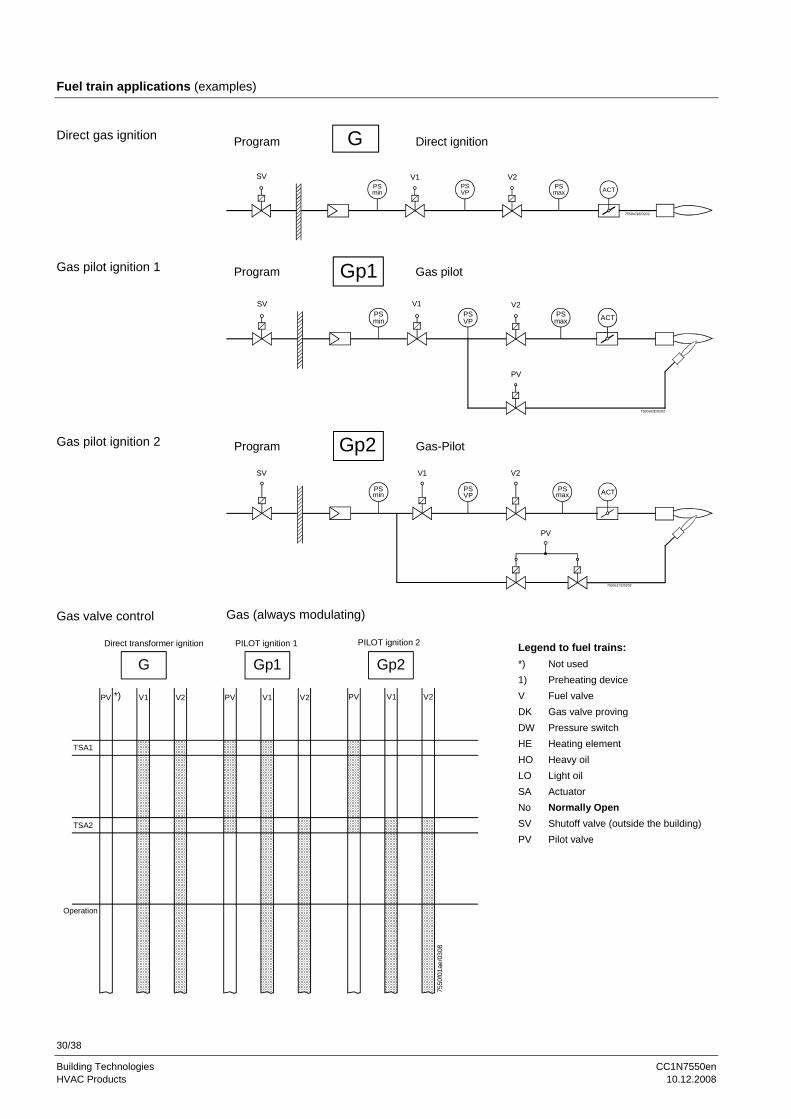
Fuel train applications (examples)
SV V1 V2
Direct ignitionGProgram
7550s01E/0202
ACTPSmax
PSmin
PSVP
SV V1
ACT
V2
Program Gp1 Gas pilot
7550s02E/0202
PV
PSmin
PSVP
PSmax
SV
PSmax ACT
V2
Program Gp2 Gas-Pilot
7550s17E/0202
PSmin
PV
V1
PSVP
Gas (always modulating)
Direct transformer ignition
G
PV V1 V2
TSA1
TSA2
Operation
*)
PILOT ignition 1
Gp1
PV V1 V2
PILOT ignition 2
Gp2
PV V1 V2
7550
f01a
e/03
08
Legend to fuel trains: *) Not used 1) Preheating device V Fuel valve DK Gas valve proving DW Pressure switch HE Heating element HO Heavy oil LO Light oil SA Actuator No Normally Open SV Shutoff valve (outside the building) PV Pilot valve
Direct gas ignition
Gas pilot ignition 1
Gas pilot ignition 2
Gas valve control

31/38
Building Technologies CC1N7550en HVAC Products 10.12.2008
Fuel train applications (examples) [cont´d]
PSmin
V1
7550s03E/0499
LOProgram
1-stage burner
V1
V2
7550s04E/0800
PSmin
LOProgram
2-stage burner
V1
V2
7550s05E/0800
PSmin
V3
LOProgram
3-stage burner
Direct ignition with light oil, multistage
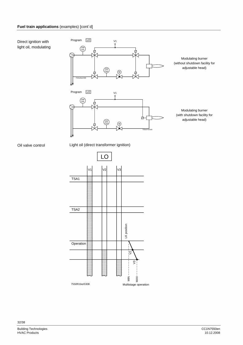
32/38
Building Technologies CC1N7550en HVAC Products 10.12.2008
Fuel train applications (examples) [cont´d]
V1
M
7550s06e/0308
DWmin
DWmax
LOProgram
Modulating burner (without shutdown facility for
adjustable head)
V1
M
7550s07e/0308
DWmin
DWmax
LOProgram
Modulating burner (with shutdown facility for
adjustable head)
Light oil (direct transformer ignition)
LO
V1 V2 V3
TSA1
TSA2
Operation
V3V2
MIN
LK p
ositi
on
Multistage operation7550f01be/0308
MAX
Direct ignition with light oil, modulating
Oil valve control

33/38
Building Technologies CC1N7550en HVAC Products 10.12.2008
Fuel train applications (examples) [cont´d]
V2
V3
No
PhV1
1)
2-stage burner
LMV5...- heavy oil direct start - input
V2
1)
V1
LMV5... - heavy oil direct start - input
Modulating burner Circulation from phase 38, max. 45 s as soon as direct heavy oil start = ON in phase 38 → Phase change in phase 40 Direct heavy oil start= OFF at the end of phase 38 → Repetition (max. 3 times in total)
Heavy oil (direct transformer ignition)
HO
Z V1 V2 V3
TSA1
TSA2
Operation
LK p
ositi
on
V3
(= s
tage
2)
Multistage operation7550f01ce/0308
Pha
se 3
8m
ax. 4
5 s
MIN
MA
X
Direct ignition with heavy oil, multistage
Direct ignition with heavy oil, modulating
Oil valve control
34/38
Building Technologies CC1N7550en HVAC Products 10.12.2008
Fuel train applications (examples) [cont´d]
Gas trains G, Gp1 and Gp2 1) can be randomly combined with oil trains LO and HO for operation with dual-fuel burners since these fuel trains operate independently.
Oil trains LOgp and HOgp are designed for ignition with a gas pilot. They must only be combined with a special gas train Gp2 for operation with a dual-fuel burner.
1) With Gp2 permitted with HW 01.C0, SW V01.40 or higher.
V1 gas V2 gasSV gas
GasPSmax
PSmin
PSVP
Light oil
ACT
PV gas
Gp2
7550s15E/0202
SV oil
LOgp V1 oilV3 oil
V2 oil
Light oil (with gas pilot ignition)
Operation
7550
f11e
/030
8
V2
multistage operation
MIN
MA
X
LOgp
G O O OPV V1 V2 V3
V3
TSA2
TSA1
Note on dual-fuel burners
Dual-fuel burner gas / light oil with gas pilot ignition
Fuel valve control
35/38
Building Technologies CC1N7550en HVAC Products 10.12.2008
Fuel train applications (examples) [cont´d]
SA
SV-gas
Gas
V2-oil
V1-oilV3-oil
SV-oil
Gp2
PV-gas
HOgp
Heavy oil (with gas pilot ignition)
Circulation from phase 44, max. 45 s as soon as direct heavy oil start = ON in phase 44: → Phase change in phase 40 Direct heavy oil start = OFF at the end of phase 44 → Repetition (max. 3 times in total)
Operation
7550
f12e
/030
8
2-stage operation
MIN
MA
X
G O O OPV V1 V2 V3
TSA2
TSA1
HOgp
Phase 44max. 45 s
Dual-fuel burner gas / heavy oil with gas pilot ignition
Fuel valve control

36/38
Building Technologies CC1N7550en HVAC Products 10.12.2008
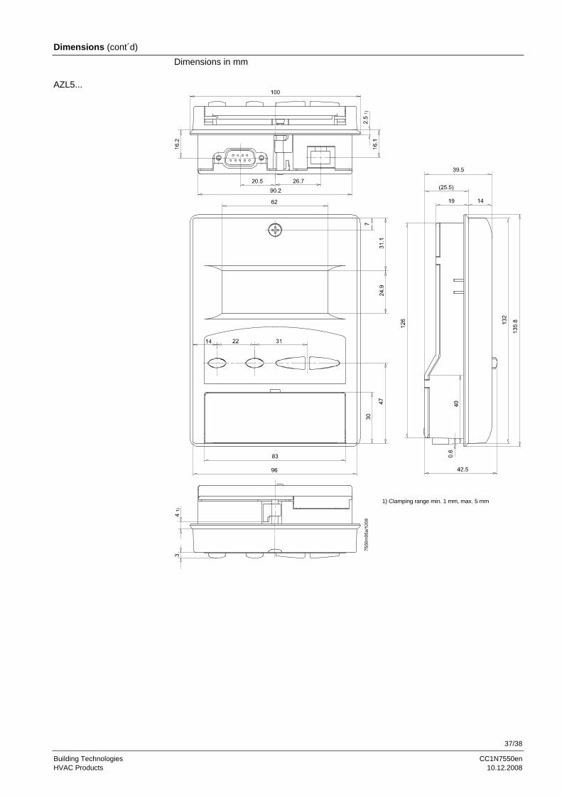
Dimensions Dimensions in mm
77
68
82,3
8 +0
,05
17
30,3 17,4 15,7 44,4
46,6 7619
78,554
162
59,5
71,6
19
232250252260
182
200
26,8 34,9 44,4 34,55
17
49,25 23,2
7550
m06
/090
8
LMV5...
37/38
Building Technologies CC1N7550en HVAC Products 10.12.2008
Dimensions (cont´d) Dimensions in mm
1) Clamping range min. 1 mm, max. 5 mm
AZL5...

38/38
Building Technologies CC1N7550en HVAC Products 10.12.2008
Dimensions (cont’d) Dimensions in mm
6633
19 369
41,5 41,5222240
83
914
216
0
7550
m03
/070
3
93.6
6.3
53 79.3
12 V coil
66.377.8
5.3
15
45
102.5
7550m04e/090610 20
12 V coil
AGG5.210: 120 V coilAGG5.220: 230 V coil
77.3
22
120 + 0.5
PLL52...
AGG5.210… / AGG5.220…
©2008 Siemens Building Technologies HVAC Products GmbH Subject to change!


