
OPERATING & SERVICE MANUAL
BUNN-O-MATIC CORPORATIONPOST OFFICE BOX 3227
SPRINGFIELD, ILLINOIS 62708-3227PHONE: (217) 529-6601 FAX: (217) 529-6644
www.bunnomatic.com
CDS-2CDS-3
BUNN®
27646.0000L 06/01 ©1997 Bunn-O-Matic Corporation

2
INTRODUCTIONThis equipment dispenses granita-type and cold liquid drinks on demand from separate hoppers. Operating
controls are accessible only to key operators.
CONTENTSIntroduction & Warranty .................................................................................... 2User Notices ...................................................................................................... 3Site Preparation, Electrical Requirements & Initial Setup ................................. 5Operating Controls............................................................................................. 8Using the Dispenser & Recommendations ...................................................... 10Recommended Cleaning .................................................................................. 12Lubrication ...................................................................................................... 13Faucet Handles ................................................................................................ 14Auger Assembly............................................................................................... 15Troubleshooting ............................................................................................... 16Service............................................................................................................. 21Refrigerant Flow Diagrams .............................................................................. 51Schematic Wiring Diagrams ............................................................................ 54
WARRANTYBunn-O-Matic Corp. (“Bunn”) warrants the equipment manufactured by it to be commercially free from defects
in material and workmanship existing at the time of manufacture and appearing within one year from the date ofinstallation. In addition:
1.) Bunn warrants electronic circuit and/or control boards to be commercially free from defects in material andworkmanship for three years from the date of installation.
2.) Bunn warrants the compressor on refrigeration equipment to be commercially free from defects in materialand workmanship for two years from the date of installation.
3.) Bunn warrants that the grinding burrs on coffee grinding equipment will grind coffee to meet original factoryscreen sieve analysis for three years from date of installation or for 30,000 pounds of coffee, whichever comes first.
This warranty does not apply to any equipment, component or part that was not manufactured by Bunn or that,in Bunn’s judgement, has been affected by misuse, neglect, alteration, improper installation or operation, impropermaintenance or repair, damage or casualty.
THE FOREGOING WARRANTY IS EXCLUSIVE AND IS IN LIEU OF ANY OTHER WARRANTY, WRITTEN ORORAL, EXPRESS OR IMPLIED, INCLUDING, BUT NOT LIMITED TO, ANY IMPLIED WARRANTY OF EITHERMERCHANTABILITY OR FITNESS FOR A PARTICULAR PURPOSE. The agents, dealers or employees of Bunn arenot authorized to make modifications to this warranty or to make additional warranties that are binding on Bunn.Accordingly, statements by such individuals, whether oral or written, do not constitute warranties and should notbe relied upon.
The Buyer shall give Bunn prompt notice of any claim to be made under this warranty by telephone at (217)529-6601 or by writing to Post Office Box 3227, Springfield, Illinois, 62708-3227. If requested by Bunn, the Buyershall ship the defective equipment prepaid to an authorized Bunn service location. If Bunn determines, in its solediscretion, that the equipment does not conform to the warranty, Bunn shall repair the equipment with no chargefor parts during the warranty period and no charge for labor by a Bunn Authorized Service Representative duringthe warranty period. If Bunn determines that repair is not feasible, Bunn shall, at its sole option, replace theequipment or refund the purchase price for the equipment.
THE BUYER’S REMEDY AGAINST BUNN FOR THE BREACH OF ANY OBLIGATION ARISING OUT OF THE SALEOF THIS EQUIPMENT, WHETHER DERIVED FROM WARRANTY OR OTHERWISE, SHALL BE LIMITED, ASSPECIFIED HEREIN, TO REPAIR OR, AT BUNN’S SOLE OPTION, REPLACEMENT OR REFUND.
In no event shall Bunn be liable for any other damage or loss, including, but not limited to, lost profits, lost sales,loss of use of equipment, claims of Buyer’s customers, cost of capital, cost of down time, cost of substituteequipment, facilities or services, or any other special, incidental or consequential damages.
27646 060401

3
USER NOTICESCarefully read and follow all notices on the equipment and in this manual. They were written for your protec-
tion. All notices are to be kept in good condition. Replace any unreadable or damaged labels.
12559.0003
CHARGEType R22, Amount 8.4 oz
Design Pressures: High 210 Low 32
27443.0000
28720.0000
27442.0000
00986.0002
27646 022500

4
USER NOTICES (CONT.)
CHARGEType R22, Amount 8.4 oz
Design Pressures: High 210 Low 32
AFTER CLEANING &BEFORE REASSEMBLY
LUBRICATION
12
3
27664.0000D 5/97 © 1996 BUNN-O-MATIC CORPORATION
1. Apply lubricant* on lip of auger seal wherecontact is made with cooling drum.
2. Apply lubricant* on outside surface ofcooling drum seal or inside bore of hopper.
3. Apply lubricant* over o-rings on faucet spoolbefore inserting into faucet housing.* Refer to product literature for Bunn
approved lubricant.
27664.0000
27444.0000 (CDS-2 Only)
28519.0000 (CDS-3 Prior to S/N CDS0019500)
CHARGEType R404A, Amount 25 oz
Design Pressures: High 320 Low 44
CHARGEType R404A, Amount 9.5 oz(269g)Design Pressures: High 215 Low 40
29373.00000 (CDSA-2 Only)
CHARGEType R404A, Amount 22 oz
Design Pressures: High 380 Low 52
29424.0000 (CDS-3 S/N CDS0019500 - UP)
27646 022500

5
SITE PREPARATIONThese dispensers are very heavy. Place them on a sturdy counter or shelf capable of supporting at least 180
lbs for the CDS2 and 250 lbs for the CDS3. They are for indoor use only.The dispenser must have at least four inches of space behind it. This space is needed for airflow, air filter
removal, and cleaning. Minimal clearance is required between the dispenser sides and the wall or anotherappliance. The dispenser performs better if not placed near any heating appliance. Leave some space so thedispenser can be moved for cleaning.
ELECTRICAL REQUIREMENTSCAUTION – Improper electrical installation will damage components. An electrician must provide electricalservice as specified below.
Model CDS-2, This dispenser has an attached cordset and requires a 2-wire, grounded, individual branchcircuit rated 120 volts ac, 15 amp, single phase, 60 Hz. The mating connector must be a NEMA 5-15R. (Referto the dataplate for exact electrical requirements.)
Model CDSA-2, This dispenser has an attached cordset and requires a 2-wire, grounded, individual branchcircuit rated 230 volts ac, 10 amp, single phase, 50 Hz. The mating connector must be a NEMA 5-15R. (Referto the dataplate for exact electrical requirements.)
Model CDS-3, This dispenser has an attached cordset and requires a 2-wire, grounded, individual branchcircuit rated 120 volts ac, 20 amp, single phase, 60 Hz. The mating connector must be a NEMA 5-20R. (Referto the dataplate for exact electrical requirements.)
Model CDSA-3, This dispenser has an attached cordset and requires a 2-wire, grounded, individual branchcircuit rated 230 volts ac, 15 amp, single phase, 50 Hz. The mating connector must be a NEMA 5-20R. (Referto the dataplate for exact electrical requirements.)NOTE – Bunn-O-Matic does not recommend the use of any extension cord with these dispensers.
27646 122200

6
INITIAL SETUPCAUTION – The dispenser is very heavy! Use care when lifting or moving it. Use at least two people to lift ormove the dispenser.1. Set the dispenser on the counter where it will be used. The CDS-3 dispenser requires a minimum of 6.0" air
clearance on both sides and at the rear of the dispenser. For optimum performance, do not let warm air fromsurrounding machines blow on the CDS-3 and DO NOT REMOVE VINYL DEFLECTOR.
NOTE – The dispenser should be level or slightly lower in front for proper operation.
6.0"MIN.
6.0"MIN.
6.0"MIN.
DO NOT REMOVE
Vinyl Deflector
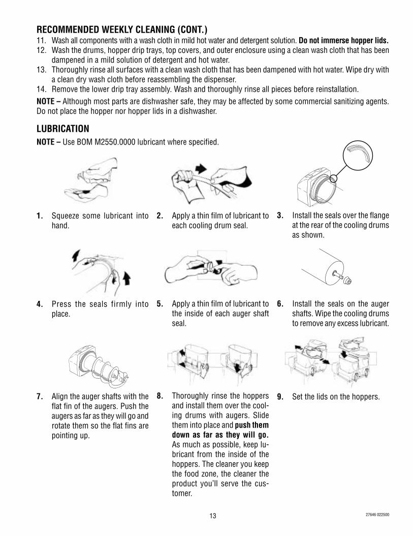
6. Press the seals firmly intoplace.
7. Apply a thin film of lubricant tothe inside of each auger shaftseal.
8. Install the seals on the augershafts. Wipe the cooling drumsto remove any lubricant.
3. Squeeze some lubricant intohand.
4. Apply a thin film of lubricant toeach cooling drum seal.
5. Install the seal over the flangeat the rear of each cooling drumas shown.
2. Remove all shipping material, including the compressor support eye-bolts, the cooling drum supports, the“Do Not Lift Here” signs from the cooling drums, and the “Rinse Before Using” signs from each hopper.
NOTE – Use BOM M2550.0000 lubricant where specified.
27646 022500

7
9. Align the auger shaft with theflat fin of the auger. Push theaugers as far as they will go androtate them so the flat fins arepointing up.
10. Thoroughly rinse the hoppersand install them over the cool-ing drums with augers. Slidethem into place and push themdown as far as they will go.As much as possible, keep lu-bricant from the inside of thehoppers. The cleaner you keepthe food zone, the cleaner theproduct you’ll serve the cus-tomer.
11. Set the lids on the hoppers.Slide front-to-back or lift off forfilling.
12. Plug in the hopper lid lampcables.
13. (CDS-2 only) Assemble the driptray.
14. (CDS-3 only) Loosen the twofront legs by turning counter-clockwise to gain approxi-mately .25" clearance. Installthe slots of the support bracketover threaded studs of the legsas shown in illustration. Tightenthe legs by turning clockwise tosecure the bracket in place.
APPROXIMATELY .25"
15. (CDS-3 only) Install the driptray.
INITIAL SETUP (CONT.)
27646 022500
8
6
5
43
2
1
COLDER
LEFTICE
RIGHTICE
6
5
43
2
1
COLDER
RIGHT
LEFT
AUGER OFFICE ICE
CENTER
AUGER OFFICE ICE
AUGER OFFICE ICE
POWEROFF ON DAY NIGHT
CENTER ICE6
5
43
2
1
COLDER
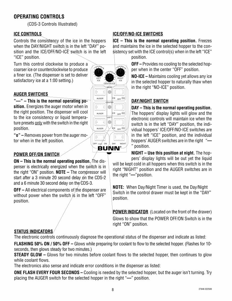
ICE CONTROLSControls the consistency of the ice in the hopperswhen the DAY/NIGHT switch is in the left “DAY” po-sition and the ICE/OFF/NO-ICE switch is in the left“ICE” position.Turn this control clockwise to produce acoarser ice or counterclockwise to producea finer ice. (The dispenser is set to deliversatisfactory ice at a 1:00 setting.)
AUGER SWITCHES”—” – This is the normal operating po-sition. Energizes the auger motor when inthe right position. The dispenser will coolto the ice consistency or liquid tempera-ture presets only with the switch in the rightposition.“o” – Removes power from the auger mo-tor when in the left position.
POWER OFF/ON SWITCHON – This is the normal operating position. The dis-penser is electrically energized when the switch is inthe right “ON” position. NOTE – The compressor willstart after a 3 minute 20 second delay on the CDS-2and a 6 minute 30 second delay on the CDS-3.OFF – All electrical components of the dispenser arewithout power when the switch is in the left “OFF”position.
ICE/OFF/NO-ICE SWITCHESICE – This is the normal operating position. Freezesand maintains the ice in the selected hopper to the con-sistency set with the ICE control(s) when in the left “ICE”
position.OFF – Provides no cooling to the selected hop-per when in the center “OFF” position.NO-ICE – Maintains cooling yet allows any icein the selected hopper to naturally thaw whenin the right “NO-ICE” position.
DAY/NIGHT SWITCHDAY – This is the normal operating position.The hoppers’ display lights will glow and theelectronic controls will maintain ice when theswitch is in the left “DAY” position, the indi-vidual hoppers’ ICE/OFF/NO-ICE switches arein the left “ICE” position, and the individualhoppers’ AUGER switches are in the right “—” position.NIGHT – Use this position at night. The hop-pers’ display lights will be out yet the liquid
will be kept cold in all hoppers when this switch is in theright “NIGHT” position and the AUGER switches are inthe right “—”position.
NOTE: When Day/Night Timer is used, the Day/NightSwitch in the control drawer must be kept in the “DAY”position.
POWER INDICATOR (Located on the front of the drawer)Glows to show that the POWER OFF/ON Switch is in theright “ON” position.
STATUS INDICATORSThe electronic controls continuously diagnose the operational status of the dispenser and indicate as listed:FLASHING 50% ON / 50% OFF – Glows while preparing for coolant to flow to the selected hopper. (Flashes for 10-seconds, then glows steady for two minutes.)STEADY GLOW – Glows for two minutes before coolant flows to the selected hopper, then continues to glowwhile coolant flows.The electronics also sense and indicate error conditions in the dispenser as listed:ONE FLASH EVERY FOUR SECONDS – Cooling is needed by the selected hopper, but the auger isn’t turning. Tryplacing the AUGER switch for the selected hopper in the right “—” position.
OPERATING CONTROLS(CDS-3 Controls Illustrated)
27646 022500

9
DAY/NIGHT TIMERThe quartz driven timer offers 24-hour programming with 96 actuators that operate in 15-minute
increments. All actuators can be individually set to the inside or outside position. The timer is located behindthe right side panel.
SETTING TIME1. Locate marker on the inner (stationary) dial that points to
outer dial. The marker is at approximately the two O’clockposition.
2. Turn outer dial clockwise until the marker is pointing to thecorrect time. The clock hands will turn with the outer dialindicating the same time as the marker. NOTE - the outer dialhas AM and PM settings.
SETTING NIGHT TIME MODE1. Locate the actuators positioned around the outer dial. Inward
position indicates day time mode and outer position indicatesnight time mode.
2. Determine the desired times that night time mode is to beginand end.
3. Position all actuators between begin and end times in theouter position.
EXAMPLE: Night Time Mode is 11:00 PM - 7:00 AM
Place the actuator at 11:00 PM to the outside position.Continue placing actuators to the outside positioncounterclock wise around the dial to 7:00 AM. All actuatorsfrom 7:00 AM to 11:00 PM must be in the inside position.
NOTE: For Day/Night Timer to operate, the Day/Night Switchin the control drawer must be kept in the “DAY” position.
Shown in“Night Time”Mode
Shown in “DayTime” Mode
OPERATING CONTROLS (Cont.)
TWO FLASHES EVERY FOUR SECONDS – A temperature error is being sensed. Call Bunn-O-Matic for Support.THREE QUICK FLASHES – Low auger torque is being sensed. Call Bunn-O-Matic for Support.
FOUR QUICK FLASHES – High auger torque is being sensed. Call Bunn-O-Matic for Support.
P1947
P1948
27646 022500

10
USING THE DISPENSER FOR GRANITA-TYPE PRODUCTS1. Slide the lid for the selected hopper to the front or back to gain access to the hopper.2. Place the premixed liquid product in the selected hopper.3. Simply press all switches to the center of the control drawer for granita products.
a. Place the POWER OFF/ON switch in the right “ON” position.b. Place the auger switch for the selected hopper in the right “—” position.c. Place the DAY/NIGHT switch in the left “DAY” position.d. Place the ICE/OFF/NO-ICE switch in the left “ICE” position.
4. Wait for the liquid to freeze to the desired consistency.
HINTS – Bunn-O-Matic recommends that the product in the dispenser be thawed each day, usually overnight.The ice granules get too large and a consistent product is difficult to maintain if left frozen for an extendedperiod of time. Place the DAY/NIGHT switch in the right “NIGHT” position for a few hours each night. Thenreturn it to the left “DAY” position when the product has thawed sufficiently. You’ll know it is in the nightposition because the hopper lid lights are out.
USING THE DISPENSER FOR COLD LIQUID PRODUCTS1. Slide the lid for the selected hopper to the front or back to gain access to the hopper.2. Place the premixed liquid product in the selected hopper.3. Simply place all switches to the center of the control drawer except the ICE/OFF/NO-ICE switch.
a. Place the POWER OFF/ON switch in the right “ON” position.b. Place the auger switch for the selected hopper in the right “—” position.c. Place the DAY/NIGHT switch in the left “DAY” position.d. Place the ICE/OFF/NO-ICE switch in the right “NO-ICE” position.
4. Wait for the liquid to cool.
27646 022500

11
OTHER RECOMMENDATIONS FOR YOUR DISPENSER• Whether liquid concentrate or granulated powder, all product must be thoroughly mixed BEFORE adding it
to the hoppers.
• For best results with granita-type products, use only products with an apparent brix of 12 or higher. Someproducts may work with an apparent brix as low as 9. Your experimentation with other products will be thebest guide in this area.
• Keep the premixed liquid product refrigerated. This reduces cooling/freezing time in the dispenser.• Keep the hoppers topped-off during peak serving periods. Add premixed liquid product as it is dispensed.
This reduces the cooling/freezing time and assures you of always having product ready to dispense.• Keep the product level in the hoppers higher than the auger. Air will become entrapped in the mixture
resulting in a clouded foamy consistency.• You may find it beneficial to turn down the ice controls to keep the ice granules from growing too large.
Refer to the operating controls on page 1-6.• Some products freeze at a lower temperature than others. You may notice frost or ice on the hoppers. This
is normal and should not be a concern.• Humidity in the air may cause sweating on the outside surfaces of the hoppers. This is to be expected and
should not be a concern. The drip trays beneath the hoppers will capture this and cause it to flow to thelower drip tray for disposal.
• Some noises are to be expected during normal operation of the dispenser. By becoming familiar with thenoises made during normal operation, you will be better able to listen for problems.
27646 022500

12
RECOMMENDED DAILY CLEANING (SUGAR & ALCOHOL PRODUCTS!)NOTE – Close the control drawer before proceeding.1. Empty all product from the hoppers.2. The driptray should be cleaned as needed for proper presentation of the product.3. Mix a packet of Kay-5 Sanitizer diluted with two-gallons of warm (120° F) water for each hopper.4. Open the lids and add the solution.5. Allow the solution to work for about five minutes with the dispenser on the ”NIGHT” position.6. Drain the sanitizing solution from the hoppers and completely rinse each with clean water.7. Wash the underside of hopper covers or powder autofill dispensers with hot water and a mild detergent
solution. Rinse all surfaces and apply some commercial sanitizing agent. Do not immerse hopper lids.NOTE – The hoppers and augers should be removed and disassembled for cleaning at least once a week using
the procedure below.
RECOMMENDED WEEKLY CLEANING (SUGAR & ALCOHOL BASED PRODUCTS!)RECOMMENDED DAILY CLEANING (DAIRY PRODUCTS!)NOTE – Close the control drawer before proceeding.1. Empty all product from the hoppers. Disconnect the hopper lid cords and remove the lids.
2. Lift the hopper up slightly, thenuse a hard plastic utensil to pryit up. Pull forward to remove.
4. Disassemble the auger forcleaning by spreading apart thelatches and removing eachpiece.
3. Pull the auger from the coolingdrum. Remove the auger shaftseal from the front of the coolingdrum and the cooling drum sealfrom the rear of the drum.
9. Remove the black plug from thefaucet spool for cleaning. Do notuse tools to remove this.
8. Roll the O-rings off of the faucetspool.
7. Squeeze the O-rings to freethem from the grooves in thefaucet spool.
6. Push the metal pin out throughthe faucet. Unscrew the plasticcap, and push the faucet spooland spring out the bottom.
5. Spread the sides of the dispensehandle and pull it off to removethe faucet pieces.
10. Pull down, then out on the airfilter at the rear of the dispenser.
27646 022500
13
1. Squeeze some lubricant intohand.
2. Apply a thin film of lubricant toeach cooling drum seal.
3. Install the seals over the flangeat the rear of the cooling drumsas shown.
4. Press the seals firmly intoplace.
5. Apply a thin film of lubricant tothe inside of each auger shaftseal.
6. Install the seals on the augershafts. Wipe the cooling drumsto remove any excess lubricant.
7. Align the auger shafts with theflat fin of the augers. Push theaugers as far as they will go androtate them so the flat fins arepointing up.
8. Thoroughly rinse the hoppersand install them over the cool-ing drums with augers. Slidethem into place and push themdown as far as they will go.As much as possible, keep lu-bricant from the inside of thehoppers. The cleaner you keepthe food zone, the cleaner theproduct you’ll serve the cus-tomer.
9. Set the lids on the hoppers.
RECOMMENDED WEEKLY CLEANING (CONT.)11. Wash all components with a wash cloth in mild hot water and detergent solution. Do not immerse hopper lids.12. Wash the drums, hopper drip trays, top covers, and outer enclosure using a clean wash cloth that has been
dampened in a mild solution of detergent and hot water.13. Thoroughly rinse all surfaces with a clean wash cloth that has been dampened with hot water. Wipe dry with
a clean dry wash cloth before reassembling the dispenser.14. Remove the lower drip tray assembly. Wash and thoroughly rinse all pieces before reinstallation.NOTE – Although most parts are dishwasher safe, they may be affected by some commercial sanitizing agents.Do not place the hopper nor hopper lids in a dishwasher.
LUBRICATIONNOTE – Use BOM M2550.0000 lubricant where specified.
27646 022500

14
14. Plug in the hopper lid lampcables.
15. Assemble the drip tray.
LUBRICATION (cont.)
12. Slide the O-rings onto thespools.
10. Reinstall the black plug into thefaucet spool. Do not lubricatethe plug.
13. Reinstall the plastic caps,springs, spools, and metal pins.Spread the dispense handlesand reinstall them.
NOTE – When reinstalling the fau-cet caps, they MUST be twistedas far as they will go. (Past thepoint where it clicks.)
FAUCET HANDLESDispensing from the hoppers will occur when the faucet handles are
installed with the handles in the upright position. (shown, left hopper)Dispensing from the hoppers will not occur when the handles are in-
stalled upside-down. (shown, right hopper) You may consider this handleposition when the product in the hoppers is not yet ready to serve. Justspread the handles or disassemble them as shown, and install them up-side down.DISASSEMBLY1. Unscrew the balls from the handle assemblies. Turn them in a coun-
terclockwise direction until they are no longer attached to the handles.2. Remove the metal sleeves from the assemblies.3. Separate the two halves of the handles and remove them from the faucet bodies.
ASSEMBLY1. Place the two halves of the handles on the faucet bodies. Check that the faucet dowel pins are
in place all the way through the faucet bodies. The dowel pins must be captured by the key-holes in the handle halves.
2. Place the metal sleeves over the threads and install the balls by turning them in a clockwise direction.
NOTE – The faucet spool plugs, faucet O-rings, cooling drum hopper seals,and auger shaft seals are to be replaced whenever they appear wornor damaged. Bunn-O-Matic recommends their replacement at leastevery six-months. Refer to page 24 for replacement instructions.
11. Apply a thin film of lubricant toeach faucet spool O-ring.
27646 122200

15
AUGER ASSEMBLY & DISASSEMBLY (EARLY AUGERS ONLY)The augers may look intimidating at first glance. But there are really just a
few pieces snapped together. Please familiarize yourself with this procedure. It’llmake cleaning and routine maintenance easier. The augers should be taken apartfor cleaning and then reassembled for use.
Auger Sections (3 req’d.)
Auger Nose
Short Auger Latch
Long Auger Latch
ASSEMBLY1. Snap one of the auger sections
to the long auger latch.
2. Snap another auger sectionin place.
3. Snap the third augersection in place.
4. Snap the auger nose ontothe last section installed.
5. With the long auger latch ontop, place the short augerlatch inside the augers andsnap it onto the assembly.
DISASSEMBLY1. Firmly pull the auger section connections apart at each slot in the long auger
latch.2. Firmly pull the connection between the auger section and auger nose apart.3. Separate the slots in the short auger latch as you remove the auger sections.
27646 022500

16
TROUBLESHOOTINGA troubleshooting guide is provided to suggest probable causes and remedies for the most likely problems
encountered. If the problem remains after exhausting the troubleshooting steps, contact the Bunn-O-MaticTechnical Service Department.
• Inspection, testing, and repair of electrical equipment should be performed only by qualified service personnel.• All electronic components have 120 volt ac and/or low voltage dc potential on their terminals. Shorting of
terminals or the application of external voltages may result in board failure.• Intermittent operation of electronic circuit boards is unlikely. Board failure will normally be permanent. If an
intermittent condition is encountered, the cause will likely be a switch contact or a loose connection at aterminal or crimp.
• Keep away from combustibles.
WARNING – • Exercise extreme caution when servicing electrical equipment.• Unplug the dispenser when servicing, except when electrical tests are specified.• Follow recommended service procedures• Replace all protective shields or safety notices
PROBLEM
Doesn't work(Switches do nothing, auger notturning, no hopper lid lights, no fan,no compressor sound.)
Hopper Lid Lights not on
PROBABLE CAUSE
1. No power or incorrect voltage tothe dispenser
2. ON/OFF Switch
1. DAY/NIGHT Switch
2. Lamp Cord Assembly
REMEDY
(A) Check for proper voltage at thewall outlet.
(B) Check circuit breakers or fuses.
(A) The ON/OFF Switch must be inthe "ON" position.
(B) Refer to Service - Dispenser ON/OFF Switch for testing procedures.See page 37.
(A) The DAY/NIGHT Switch must bein the "DAY" position.
(B) Refer to Service - DAY/NIGHTSwitch for testing procedures. Seepage 36.
(A) The lamp cord must be pluggedinto the lamp cord connector.
(B) Refer to Service - Lamp CordAssembly for testing procedures. Seepage 42.
27646 122200

17
TROUBLESHOOTING (cont.)REMEDY
(A) The circuit breaker must not betripped.
(B) Refer to Service - Circuit Breakerfor testing procedures. See page 27.
Remove the lamps and check forcontinuity across the base and tip.Replace if necessary.
Refer to Service - Transformer fortesting procedures. See page 49.
Refer to Service - Lamp Holder/Socket Assembly for testing proce-dures. See page 44.
(A) The auger switch must be in the"ON" position.
(B) Refer to Service - Auger ON/OFFSwitch(es) for testing procedures.See page 26.
Refer to Service - Auger MotorCapacitor(s) for testing procedures.See page 23.
Refer to Service - Auger Motor(s) fortesting procedures. See page 22.
Refer to Service - Fan Motor fortesting procedures. See page 39.
The fan motor will run for approxi-mately two minutes after compres-sor shuts off.
PROBABLE CAUSE
3. Circuit Breaker
4. Lamps
5.Transformer
6. Lamp Holder/Socket Assy
1. Auger ON/OFF Switch(es)
2. Auger Motor Capacitor(s)
3. Auger Motor(s)
1. Fan Motor
1. Time Delay
PROBLEM
Hopper Display Lights not on (cont.)
Auger Motor won't turn
Fan not spinning (With adjustmentBoard L.E.D.s ON steadily for twominutes)
Fan spins after compressor shutsoff
27646 122200

18
TROUBLESHOOTING (cont.)PROBLEM
Compressor not running(With Adjustment Board L.E.D.s ONsteadily for two minutes)
Compressor runs but will not cool(With adjustment Board L.E.D.sflashing once every 4 seconds)
Compressor runs but will not cool(With adjustment Board L.E.D.sflashing twice every 4 seconds)
Compressor runs but will not cool(With adjustment Board L.E.D.sflashing 3, or 4 times every 4seconds)
PROBABLE CAUSE
1. Power cord
2. Fuse
3. Contactor
4. Electronic Control
5. Compressor Start Relay
6. Thermal Overload Protector
7. Compressor Start Capacitor
8. Compressor
1. Auger not turning
1. Temperature Sensor Assembly
1. Torque Sensor Circuit Board
REMEDY
The dispenser must not be connectedwith an extension cord. Refer to Elec-trical Requirements.
Refer to Service - Fuse and FuseHolder for testing procedures. Seepage 40.
Refer to Service - Contactor for test-ing procedures. See page 34.
Refer to Service - Electronic Controlfor testing procedures. See page 38.
Refer to Service - Compressor StartRelay for testing procedures. Seepage 28 (CDS-2) or 31 (CDS-3).
Refer to Service - Compressor Ther-mal Overload Protector for testingprocedures. See page 28 (CDS-2) or31 (CDS-3).
Refer to Service - Compressor StartCapacitor for testing procedures. Seepage 28 (CDS-2) or 31 (CDS-3).
Refer to Service - Compressor fortesting procedures. See page 28(CDS-2) or 31 (CDS-3).
Refer to Troubleshooting - AugerMotor Won't Turn on previous page.
Refer to Service - Temperature Sen-sor Assembly for testing procedures.See page 47.
Refer to Service - Torque SensorCircuit Board for testing procedures.See page 48.
27646 122200

19
TROUBLESHOOTING (cont.)PROBLEM
Compressor runs but will not cool(With adjustment Board L.E.D.sflashing 3, or 4 times every 4seconds) (cont.)
Product Won't Freeze
Product freezes but ice granules aretoo fine or too large
Dispenser is making unusual noises.(Some noises are a normal occurancewith this type of device. You need tobecome familiar with those that arenormal, to determine when they havebecome unusual.)
PROBABLE CAUSE
2. Air Filter or Condenser
3. Refrigerant
1. DAY/NIGHT Switch
2. Sugar content of product
3. Voltage Divider
1. Ice adjustment
2. Sugar content of product
1. Lubrication
2. Cooling Drum(s)
REMEDY
The air filter and condenser MUSTbe cleaned regularly. Any dustbuildup will affect cooling ability.
Have a qualified service person checkthe refrigerant charge.
(A) The DAY/NIGHT Switch must bein the "DAY" position.
(B) Refer to Service - DAY/NIGHTSwitch for testing procedures. Seepage 36.
Bunn recommends the use of prod-ucts with an apparent brix of 12 orhigher.
Refer to Service - Voltage Divider fortesting procedures. See page 50.
Turn the Ice control for the desiredhopper a small amount clockwise toincrease the ice granule size or coun-terclockwise to decrease the ice gran-ule size.
Adjust the sugar content of the prod-uct. Increasing the apparent brix re-sults in finer ice granules. Decreas-ing the apparent brix results in largerice granules.
Always lubricate the dispenser asdirected in this manual before reas-sembling and using the dispenser.
Use the cooling drum support todetermine that the auger shaft is stillthe proper distance from the hopperdrip tray. The cooling drum may begently lifted to return it to the neces-sary horizontal position. Refer toService - Cooling Drum Alignment.See page 35.
27646 122200

20
TROUBLESHOOTING (cont.)PROBLEM
Dispenser is making unusual noises.(Some noises are a normaloccurance with this type of device.You need to become familiar withthose that are normal, to determinewhen they have become unusual.)(cont.)
Product is leaking into the inside ofthe drum.
PROBABLE CAUSE
3. Fan Motor
4. Auger Motor(s)
1. Worn Shaft
2. Worn Seals
REMEDY
Remove the air filter at the rear of thedispenser and listen for fan motornoise. Replace the motor if exces-sively noisy.
Place the Auger switches in the "ON"position and the ICE/OFF/NO-ICEswitches in the “OFF” position. Lis-ten for auger motor noise. Replacethe motor if excessively noisy.
Replace Shaft. Refer to Service -Auger Shaft Assembly. See page 24.
Replace Cooling Drum Seal. Refer toService - Auger Shaft Assembly. Seepage 24.
27646 122200
21
Auger Motors .................................................................................................. 22Auger Motor Capacitors ................................................................................... 23Auger Shaft Assembly ..................................................................................... 24Auger ON/OFF Switches ................................................................................... 26Circuit Breaker ................................................................................................. 27Compressor (CDS-2) ....................................................................................... 28 (Compressor, Compressor Start Capacitor, Compressor Start Relay, Thermal Overload Protector)
Compressor (CDS-3) ....................................................................................... 31 (Compressor, Compressor Start Capacitor, Compressor Start Relay, Thermal Overload Protector)
Contactor ......................................................................................................... 34Cooling Drum Alignment ................................................................................. 35Day/Night Switch ............................................................................................. 36Dispenser ON/OFF Switch ................................................................................ 37Electronic Control ............................................................................................ 38Fan ................................................................................................................... 39Fuse and Fuse Holder ...................................................................................... 40ICE/OFF/NO ICE Switch .................................................................................... 41Lamp Cord Assembly ...................................................................................... 42Lamp Cord Connector...................................................................................... 43Lamp Holder/Socket Assembly ........................................................................ 44L.E.D./Adjustment Board ................................................................................. 45Solenoids ......................................................................................................... 46Temperature Sensor Assembly ........................................................................ 47Torque Sensor Circuit Board ............................................................................ 48Transformer ..................................................................................................... 49Voltage Divider ................................................................................................ 50Coolant Schematics ......................................................................................... 51Electrical Schematics ....................................................................................... 54
SERVICEThis section provides procedures for testing and replacing various major components used in this dispenser
should service become necessary. Refer to Troubleshooting for assistance in determining the cause of anyproblem.WARNING - Inspection, testing, and repair of electrical equipment should be performed only by qualified servicepersonnel. The dispenser should be disconnected from the power source when servicing, except when electricaltests are required and the test procedure specifically states to connect the dispenser to the power source.
COMPONENT ACCESSWARNING - Disconnect the dispenser from the power source before the removal of any panel or the replacementof any component.
All components are accessible by removal of the auger motor cover, lower drip tray, front cover and the left andright side covers.
Refer to the contents listing for component location.
Contents
27646 122200

22
aside with wires attached.4. Disconnect the auger motor terminal from the
terminal on the main wiring harness.5. Remove the three remaining #8 locking screws
securing the auger motor mounting bracket tocooling drum mounting bracket.
6. Remove motor with mounting bracket, drip tray,split pin and torsion spring bearing as an assem-bly.
NOTE: When removing or installing the motor be surethe split pin in the motor shaft is turned to a positionthat will clear the torque sensor circuit board.7. Install new motor with mounting bracket, drip
tray, split pin and torsion spring bearing usingthree #8 locking screws onto the cooling drumbracket.
8. Install the auger motor capacitor on the lower rightside of the auger mounting bracket, using theremaining #8 locking screw.
9. Connect the auger motor terminal to the terminalon the main wiring harness.
10. Refer to Fig. 2 when reconnecting the wires.
FIG. 2 AUGER MOTOR TERMINALS P1321
LocationThe auger motors are located at the upper rear of
the dispenser chassis inside the auger motor covers.
Test Procedures1. Disconnect the dispenser from the power source.2. Disconnect the wires from the motor to be tested.3. With a voltmeter, check the voltage across the
white/brown wire for the left motor, the white/bluewire for the right motor, or the grey wire for thecenter motor and the white/black wire. Place theappropriate auger switch in the “-” (“ON”) posi-tion. Connect the dispenser to the power supply.The indication must be:a) 120 volts ac for 120 volt models.b) 230 volts ac for 230 volt models.
4. Disconnect the dispenser from the power supply.If voltage is present as described, replace the motor.If voltage is not present as described, refer to theWiring Diagram and check the dispenser wiring har-ness.
Removal and Replacement1. Remove the two #8 locking screws securing the
auger motor cover to the cooling drum mountassembly.
2. Remove the cover and set aside for reassembly.3. Remove the #8 locking screw on the lower right
side of the auger motor mounting bracket secur-ing the auger motor run capacitor. Set capacitor
SERVICE(CONT.)
AUGER MOTORS
FIG. 1 AUGER MOTORS P1341
27646 022500

23
FIG. 4 AUGER MOTOR CAPACITOR TERMINALS
SERVICE (CONT.)
AUGER MOTOR CAPACITOR
FIG. 3 AUGER MOTOR CAPACITORS P1341
Location:The auger motor capacitors are located on the
lower right side of the auger motor mounting bracketinside the auger motor covers.
Test Procedures:1. Disconnect the dispenser from the power source.2. Disconnect the wires from the capacitor to be
tested.3 With a voltmeter, check for voltage across the
white/blue wire on the right capacitor, the white /brown wire on the left capacitor, or the grey wireon the center capacitor and the white/black wire onthe auger motor terminal. Place the appropriateauger switch in the “-” (“ON”) position. Connectthe dispenser to the power source.The indicationmust be:a) 120 volts ac for 120 volt models.b) 230 volts ac for 230 volt models.
4. Disconnect the dispenser from the power source.If voltage is present as described, proceed to #5.If voltage is not present as described, refer to theWiring Diagram and the dispenser wiring harness.5. Check for continuity across the auger motor ca-
pacitor terminals.If continuity is present as described, reconnect thewires to the auger motor capacitor.If continuity is not present as described, replace theauger motor capacitor.
P1324
Removal and Replacement1. Remove the two #8 locking screws securing the
auger motor cover to the cooling drum mount assy.2. Remove the cover and set aside for reassembly.3. Disconnect the wires from the auger motor ca-
pacitor terminals.4. Remove the #8 locking screw on the lower right
side of the auger motor mounting bracket secur-ing the auger motor capacitor.
5. Install a new capacitor on the lower right side ofthe auger mounting bracket and secure with a #8locking screw.
6. Reconnect the wires to the capacitor terminals.7. Refer to Fig. 4 when reconnecting the wires.
27646 022500

24
SERVICE (cont.)
AUGER SHAFT ASSEMBLY
Auger Shaft Assy
Auger Shaft BushingCooling Drum SealAuger Shaft Seal
Hopper Drum Seal
FIG. 5 AUGER SHAFT ASSEMBLY
Location:The Auger Shaft Assembly is located in each of
the cooling drums.
Removal and Replacement:1. Drain, remove and clean hopper; refer to the Rec-
ommended Daily Weekly Cleaning Section of thismanual, page 12, for proper cleaning procedures.Discard the auger shaft seal, hopper/drum sealand faucet spool o-rings.
2. Remove the #8 locking screws securing augermotor cover to the cooling drum mount assem-bly; remove cover and set aside for reassembly.
3. Remove the #8 locking screw on the lower rightside (viewed from front) of the auger motormounting bracket securing the auger motor runcapacitor. Set capacitor aside with wires attached.
4. Disconnect the auger motor terminal from the ter-minal on the main wiring harness.
5. Remove the remaining #8 locking screws secur-ing the auger motor mounting bracket to coolingdrum mounting bracket.
6. Remove motor with mounting bracket, drip tray(if present) split pin and torsion spring bearing asan assembly.
NOTE - When removing or installing motor and shaftassemblies, be sure the split pins are turned to a po-sition that will clear the torque sensor circuit board.
7. Pull the auger shaft assembly straight out of cool-ing drum. Inspect the shaft for abnormal wear orscoring.
8. From the front of dispenser, remove the seal andblue bushing from cooling drum and discard them.
9. Clean seal and busing surfaces of the cooling drumvery thoroughly. All old lubricant must be re-moved.
10. Refer to Fig 6A and slip new blue bushing intocooling drum. Lightly lube I.D. of bushing with#M2550.0000 “Lubri-film” provided in Kit#28106.0000 (CDS-2) or #28106.0001 (CDS-3).Do not use anything such as a cotton swab thatmight leave lint or unravel. DON NOT GET ANYLUBE ON THE SEAL COUNTERBORE SURFACE.
11. Lightly lube I.D. of new cooling drum seal with#M2550.0000, provided in kit. Use care not to getany lube on O.D. of seal. Place seal on insertiontool #28395.0000, as shown in Fig. 6B. Make sureopen face of seal is toward cooling drum.
12. Push seal into bore until it is firmly seated; re-move tool.
13. Clean the auger shaft assembly, then wipe a smallamount of #M2550.0000 “Lubri-film” (providedin kit) over the first two inches of the front end ofthe shaft.
14. Place a small amount of #29563.0000 “Krytox”lubricant (provided in kit in a plastic cap) on theend of the motor shaft (about 1 1/2") and a thinfilm in the groove. Install auger shaft assemblyonto the motor shaft. See Fig. 6C. Do not use toomuch “Krytox” lubricant.
NOTE - This is the only place “Krytox” lubricant isused.
15. Assemble motor/shaft assembly as shown in Fig.6C, then install assembly into cooling drum. Makesure the pins do not hit the sensor board and cool-ing drum seal is not dislodged as the shaft passesthrough.
16. Secure motor and capacitor to the cooling drummounting bracket. Install rear motor cover.
17. Refer to Initial Setup for hopper assembly and in-stallation procedures. Be sure to use new hopper/drum seal, auger shaft seal and faucet spool o-rings when reassembling.
P1758
27646 122200

25
SERVICE (cont.)
AUGER SHAFT ASSEMBLY(cont.)
��������������@@��ÀÀ��@@��ÀÀ��@@��ÀÀ��yy
����@@@@����ÀÀÀÀ����@@@@����ÀÀÀÀ����@@@@����ÀÀÀÀ����yyyy
����
@@@@
����
ÀÀÀÀ
����
@@@@
����
ÀÀÀÀ
����
@@@@
����
ÀÀÀÀ
����
yyyy
����
@@@@
����
ÀÀÀÀ
����
@@@@
����
ÀÀÀÀ
����
@@@@
����
ÀÀÀÀ
����
yyyy
FIG. 6A AUGER SHAFT BUSHING
Lightly lube the bushing I.D.with M2550.0000 “Lubri-Film”
Do NOT get any Lube on thissurface
P1759
FIG. 6B COOLING DRUM SEALP1760
Open face of seal awayfrom tool
Cooling Drum SealSeal Insertion Tool
FIG. 6C MOTOR/SHAFT ASSEMBLYP1761
Lube about 1 1/2" ofshaft and in the groovewith #29563.0000“Krytox” Lubricant
Auger Shaft Assy
Lube about 2.0" of shaftwith #M2550.0000 “Lubri-film”
27646 122200

26
If continuity is present as described, the auger switchis operating properly.If continuity is not present as described, replace theauger switch.
Removal and Replacement:1. Pull the dispenser drawer out until the drawer hits
the drawer stop. Using a screwdriver gently pry upon the drawer stop and remove the drawer fromthe dispenser.
2. Remove the four #8-32 locking screws securingthe switch panel to the drawer.
3. Lift the switch panel with wires and L.E.D./adjust-ment board out as an assembly.
4. Turn switch panel over and remove the wires fromthe auger switch that is to be replaced.
5. Compress the clips on the back of the control paneland gently push switch through the opening.
6. Push the new switch into the opening, with the “o”on the switch to the outside, until the clips snapinto position.
7. Reconnect the wires to the switch. Refer to Fig. 8when reconnecting wires.
8. Position the switch panel inside the drawer andsecure with four #8-32 locking screws.
9. Reinstall drawer.
FIG. 8 AUGER SWITCH TERMINALS P1336
FIG. 7 AUGER ON/OFF SWITCHESP1343
Location:The auger switches are located inside the dispenser
drawer.
Test Procedures:1. Disconnect the dispenser from the power source.2. Disconnect the white/green wire from the switch
to be tested and white/black wire from contactorlocated on the outside bottom of the componentbracket .
3. With a voltmeter, check the voltage across thewhite/green and the white/black wires and the“ON/OFF” switch in the “ON” position. Connect thedispenser to the power source. The indicationmust be:a) 120 volts ac for 120 volt models.b) 230 volts ac for 230 volt models.
4. Disconnect the dispenser from the power source.
If voltage is present as described, reconnect the white/black wire to the contactor and proceed to #5.If voltage is not present as described, refer to theWiring Diagram and check the dispenser wiring har-ness.
5. Remove the white/blue wire from the right augerswitch, the white/brown wire from the left augerswitch, or the grey wire from the center auger switch.
6. With the auger switch to be tested in the “ON”position check for continuity across the terminals.Continuity must not be present when the switch isin the “OFF” position.
SERVICE (cont.)
AUGER ON/OFF SWITCHES
27646 122200

27
R22
FIG. 9 CIRCUIT BREAKER P1342
SERVICE (cont.)
CIRCUIT BREAKER
Location:The circuit breaker is located inside the dispenser
on the upper left side of the component bracket.
Test Procedures:1. Disconnect the dispenser from the power source.2. Remove the wires from the circuit breaker.3. Check for continuity between the terminals. Con-
tinuity must be present between the terminals.If continuity is present as described the circuit breakeris functioning properly.If continuity is not present as described, press thereset button and repeat step #3, if continuity is notpresent as described, replace the circuit breaker.
Removal and Replacement:1. Remove the four #8-32 locking screws securing
the component bracket to the chassis.2. Tip the top of the component bracket forward far
enough to allow access to the rear of the circuitbreaker.
3. Remove the wires from the circuit breaker.4. Compress the clips on the back side of the compo-
nent bracket and gently push the circuit breakerthrough the opening in the component bracket.
FIG. 10 CIRCUIT BREAKER TERMINALSP1330
5. Push the new circuit breaker into the opening inthe component bracket until the clips snap intoposition.
6. Reconnect the wires to the circuit breaker.7. Position the component bracket in chassis and
secure with four #8-32 locking screws.8. Refer to Fig. 10 when reconnecting the wires.
27646 122200
RED from Transformer
RED from Main Harness

28
120V COMPRESSORS
SERVICE (cont.)
COMPRESSOR & COMPONENTS (CDS-2)
R22
FIG. 11 COMPRESSOR ASSY
R22
R22
3 2 5 6
FIG. 12 COMPRESSOR ELECTRICAL COMPONENTSP1344
Test Procedures:WARNING: The compressor start capacitor must beproperly discharged before proceeding.
Compressor Start Relay: Refer to FIG. 121. Disconnect the dispenser from the power source.2. Remove compressor terminal cover retainer (6)
and compressor terminal cover (5).3. Disconnect the black wire from the thermal over-
load protector (3) and white/black wire from thecompressor start relay (1).
4. With a voltmeter, check voltage across the blackwire and the white/black wire and the ON/OFFswitch in the “ON” position, DAY/NIGHT switch inthe “DAY” position and the ICE/OFF/NO ICE switchin the “ICE” position. Connect the dispenser to thepower source. The indication must be 120 volts acfor two wire 120 volt models or 230 volts ac for twowire 230 volt models.
5. Disconnect the dispenser from the power source.If voltage is present as described, proceed to #6.If voltage is not present as described, refer to theWiring Diagram and check the dispenser wiring har-ness.6. Disconnect the two black wires from the compres-
sor start capacitor.7. Remove relay from the compressor.8. Check for continuity across the upper left terminal
and the right pin socket on the rear of the relay.If continuity is present as described, the compressorstart relay is operating properly.If continuity is not present as described, replace relay.
Compressor:1. With the compressor start relay (1) removed,
disconnect the black wire from the compressor.2. Check for continuity across the terminal on the
compressor and the left pin on the compressor.If continuity is present as described, the electrical partof the compressor is operating properly.If continuity is not present as described, replace thecompressor.
Thermal Overload Protector:1. Check for continuity across the terminals on the
thermal overload protector (3).If continuity is present as described, the thermal over-load protector is operating properly.If continuity is not present as described, replace thethermal overload protector.
Location:The compressor assy is located inside the front of
the dispenser chassis.
1. Compressor Start Relay2. Overload Protector Retainer3. Thermal Overload Protector4. Compressor Start Capacitor5. Compressor Terminal Cover6. Compressor Terminal Cover Retainer7. Compressor Run Capacitor
P1342
1 4
431
5 6 7
230V COMPRESSORS
27646 122200

29
SERVICE (cont.)
COMPRESSOR & COMPONENTS (CDS-2) (cont.)Compressor Start Capacitor:1. Check for continuity across the terminals on the
compressor start capacitor.If continuity is present as described, the start capaci-tor is operating properly.If continuity is not present as described, replace thecapacitor.NOTE: If all the electrical components are operating prop-erly and the compressor does not operate, there is aninternal mechanical problem. Replace the compressor.
Removal and Replacement:
Compressor Assy:NOTE: Before removal of any refrigeration componentthe refrigerant in the system must be reclaimed by alicensed refrigeration repair person.1. Disconnect the tubes from the condenser and the
accumulator.2. Disconnect the compressor wiring harness from
the dispenser main wiring harness.3. Remove the four .25-20 keps nuts and washers
securing the compressor to the chassis. Set nutsand washers aside for reassembly.
4. Remove the four #8-32 locking screws securingthe component bracket to the dispenser chassis.
5. Disconnect the wires from the circuit breaker, fuseholder, transformer, electronic control and thecontactor.
6. Remove component bracket with circuit breaker,fuse holder, transformer, electronic control andcontactor as an assembly. Set component bracketand screws aside for reassembly.
7. From the right side of the dispenser lift the com-pressor assembly over the four studs in the chas-sis and remove compressor.
8. Install new compressor over the four studs in thedispenser chassis with the fill valve to the left sideof the dispenser.
9. Secure compressor to the dispenser chassis usingfour .25-20 keps nuts and washers.
10. Reconnect the wires to the components on thecomponent bracket and plug the main wiring har-ness into the electronic control.
NOTE: When reconnecting wires refer to Fig. 10 forcircuit breaker, Fig. 34 for fuse holder, Fig. 51 for trans-
former and Fig. 22 for contactor.11. Position the component bracket in the chassis and
secure with four #8-32 locking screws.12. Reconnect tubes from the condenser and the
accumulator to the compressor.13. Evacuate the system.NOTE: When replacing the compressor it is recom-mended that the dryer also be replaced.14. Recharge 120V system with 8.4 oz. of Type R22
refrigerant. Design Pressures: High 210 - Low 32Recharge 230V system with 9.5 oz. of Type 404Arefrigerant. Design Pressures: High 215 - Low 40
NOTE: The charging of the system must be done by alicensed refrigeration repair person.
Compressor Start Capacitor: Refer to FIG. 12WARNING: The compressor start capacitor must beproperly discharged before proceeding.1. Remove terminal cover retainer (6) and terminal
cover (5). Set aside for reassembly.2. Disconnect the two leads from the capacitor.3. Pry the end of the capacitor mounting bracket off of
the boss on the capacitor and remove the capacitor.4. Install new capacitor on the capacitor mounting
bracket.5. Refer to Fig. 13 and reconnect the wires to the
capacitor.6. Reinstall terminal cover (5) and cover retainer (6).
FIG. 13 COMPRESSOR START CAPACITORTERMINALS
P1340
120V DISPENSERS
230V DISPENSERS
27646 122200

30
Compressor Thermal Overload Protector (230V):Refer to FIG. 121. Remove terminal cover retainer (6) and terminal
cover (5).2. Disconnect the black wire from the thermal over-
load protector.3. Pull thermal overload protector off of the com-
pressor pin and discard.4. Push new thermal overload protector onto the
compressor pin.5. Refer to Fig. 15 and reconnect the wire.6. Reinstall terminal cover (5) and cover retainer (6).
SERVICE (cont.)
COMPRESSOR & COMPONENTS (CDS-2) (cont.)
Compressor Thermal Overload Protector (120V): Re-fer to FIG. 121. Remove terminal cover retainer (6) and terminal
cover (5).2. Disconnect the wire from thermal overload protector
to the compressor and the wire from the compressorwiring harness to the thermal overload protector.
3. Remove overload protector retainer (2) and ther-mal overload protector (3) as an assembly.
4. Remove retainer (2) from overload protector (3)and discard overload protector.
5. Install retainer (2) on new overload protector (3).6. Install retainer (2) and overload protector (3) on
the compressor terminal bracket.7. Refer to Fig. 15 and reconnect the thermal over-
load protector wires.8. Reinstall terminal cover (5) and cover retainer (6).
FIG. 15 THERMAL OVERLOAD PROTECTORTERMINALS
P1339
FIG. 14 COMPRESSOR START RELAYTERMINALS
P1338
120V DISPENSERS
230V DISPENSERS
120V DISPENSERS
230V DISPENSERS
Compressor Start Relay: Refer to FIG. 121. Remove the terminal cover retainer (6) and the
terminal cover (5)WARNING: The compressor start capacitor must beproperly discharged before proceeding.2. Disconnect the wires from the compressor start
relay.3. Pull relay (1) off of the compressor pins and
discard.4. Push new relay onto the compressor pins.5. Refer to Fig. 14 and reconnect the wires.6. Reinstall terminal cover (5) and cover retainer (6).
Compressor Run Capacitor (230V Dispensers Only):Refer to FIG. 121. Remove terminal cover retainer (6) and terminal
cover (5).2. Disconnect the run capacitor leads.3. Remove the #6 crimptite screw securing the run
capacitor to the rear of the component bracket.4. Remove run capacitor and discard.5. Place new run capacitor on the rear of component
bracket and secure with #6 crimptite screw.6. Refer to Fig. 15A and reconnect the wires.
FIG. 15A COMPRESSOR RUN CAPACITORTERMINALS
P1816
27646 122200

31
SERVICE (cont.)
COMPRESSOR & COMPONENTS (CDS-3)
FIG. 16 COMPRESSOR &COMPONENT LOCATIONS
FIG. 17 COMPRESSOR THERMALOVERLOAD PROTECTOR LOCATION
3. Disconnect the black wire to the thermal overloadprotector (4), the white and black or red wires tothe compressor.
4. With a voltmeter, check voltage across the blackwire removed from the thermal overload protectorand the white wire with the ON/OFF switch in the“ON” position, DAY/NIGHT switch in the “DAY”position and the ICE/OFF/NO ICE switch in the“ICE” position. Connect the dispenser to the powersource. The indication must be:a) 120 volts ac for 120 volt models.b) 230 volts ac for 230 volt models.
5. Disconnect the dispenser from the power source.If voltage is present as described, proceed to #6.If voltage is not present as described, refer to theWiring Diagram and check the dispenser wiring har-ness.6. Disconnect the two black wires from the compres-
sor start capacitor.7. Check for continuity across contacts 1 & 2 of the
relay.If continuity is present as described, the compressorstart relay is operating properly.If continuity is not present as described, replace relay.
Compressor:1. With the compressor start relay (1) removed,
disconnect the black or red wire from the com-pressor.
2. Check for continuity across the terminal on thecompressor and the left pin on the compressor.
If continuity is present as described, the electrical partof the compressor is operating properly.If continuity is not present as described, replace thecompressor.
Thermal Overload Protector:1. Check for continuity across the terminals on the
thermal overload protector.If continuity is present as described, the thermal over-load protector is operating properly.If continuity is not present as described, replace thethermal overload protector.
Compressor Start Capacitor:1. Check for continuity across the terminals on the
compressor start capacitor.If continuity is present as described, the start capaci-tor is operating properly.If continuity is not present as described, replace thecapacitor.
Location:The compressor assy is located inside the front of
the dispenser chassis.
1. Compressor Start Relay2. Compressor Start Capacitor3. Compressor Run Capacitor4. Thermal Overload Protector5. Overload Protector Retainer6. Compressor Terminal Cover7. Compressor Terminal Cover Retainer
Test Procedures:Compressor Start Relay: Refer to FIG. 17WARNING: The compressor capacitors must be prop-erly discharged before proceeding.1. Disconnect the dispenser from the power source.2. Remove the compressor terminal cover retainer
(7) and compressor terminal cover (6).
P1558.30
P1819
1
45
67
2 3
27646 122200

32
SERVICE (cont.)
COMPRESSOR & COMPONENTS (CDS-3) (cont.)Compressor Run Capacitor:1. Check for continuity across the terminals on the
compressor run capacitor.If continuity is present as described, the run capacitoris operating properly.If continuity is not present as described, replace thecapacitor.NOTE: If all the electrical components are operating prop-erly and the compressor does not operate, there is aninternal mechanical problem. Replace the compressor.Removal and Replacement:Compressor Assy:NOTE: Before removal of any refrigeration componentthe refrigerant in the system must be reclaimed by alicensed refrigeration repair person.1. Disconnect the tubes from the condenser, accu-
mulator also remove access valve and tube..2. Disconnect the compressor wiring harness from
the dispenser main wiring harness.3. Remove the four .312"-18 screws, keps nuts and
washers securing the compressor to the chassis.Set screws, nuts and washers aside for reassem-bly.
4. Remove the four #8-32 locking screws securingthe component bracket to the dispenser chassis.
5. Pull the component bracket, with wires attached,out of the chassis far enough to gain access to thecompressor.
6. Disconnect the compressor wiring harness fromthe compressor.
7. Remove the two #8-32 screws securing thecontactor mounting bracket to the dispenser base.
8. Remove the contactor mounting bracket, contactor,contactor cover and the compressor wiring har-ness as an assembly. Set aside for reassembly.
9. Disconnect the fan leads from the main wiringharness.
10. Remove the three #6 thread cutting screws secur-ing the fan to the condenser shroud. Remove thefan and set aside for reassembly.
11. Slide the compressor out the right side of thedispenser.
12. Remove the four grommets and sleeves from theold compressor and install them on the new com-pressor.
13. Slide new compressor into position on the dis-penser chassis, with the tube connections to thefront.
14. Secure compressor to the dispenser chassis usingfour .312"-18 screws, washers and nuts.
15. Install the fan on the condenser shroud and securewith three #6 thread cutting screws.
16. Reconnect the leads on the fan to the main har-ness.
17. On dispensers serial number CDS0019500 - upinstall the contactor bracket, contactor, contactorcover and compressor wiring harness as an as-sembly. Secure contactor bracket to the chassisusing two #8-32 screws.
18. Refer to Fig.17A and reconnect the wires to thecompressor.
19. Position the component bracket in the chassis andsecure with four #8-32 locking screws.
20. Reconnect tubes from the condenser and the ac-cumulator to the compressor, also reconnect ac-cess valve and tube.
21. Evacuate the system.NOTE: When replacing the compressor it is recom-mended that the dryer also be replaced.22. Dispensers prior to serial number CDS0019500
recharge system with 25 oz. of Type R404A refrig-erant. Design Pressures: High 320 - Low 44Dispensers serial number CDS0019500 - up re-charge system with 22 oz of type R404A refriger-ant. Design Pressures: High 380 - Low 52
NOTE: The charging of the system must be done by alicensed refrigeration repair person.
RED fromRelay T2WHI fromRelay T4BLK fromRelay T-5
FIG. 17A COMPRESSOR TERMINALSP1819
27646 122200

33
SERVICE (cont.)
COMPRESSOR & COMPONENTS (CDS-3) (cont.)
Compressor Thermal Overload Protector: Refer to FIG.171. Remove terminal cover retainer (7) and terminal
cover (6).2. Remove the wire from thermal overload protector
from the compressor wiring harness to the thermaloverload protector.
3. Remove overload protector retainer (5) and ther-mal overload protector (4) as an assembly
4. Remove retainer (5) from overload protector (4)and discard overload protector.
5. Install retainer (5) on new overload protector (2).6. Install retainer (5) and overload protector (4) on
the compressor terminal bracket.7. Refer to Fig. 20 and reconnect the thermal over-
load protector wires.8. Reinstall terminal cover (6) and cover retainer (7).
FIG. 20 THERMAL OVERLOAD PROTECTORTERMINALS
Compressor Start RelayWARNING: The compressor start capacitor must beproperly discharged before proceeding.1. Disconnect the wires from the compressor relay.2. Remove the #6-32 screw securing the relay to the
rear of the component bracket.3. Remove and discard relay.4. Install new relay on the rear of the component
bracket and secure with a #6-32 screw.5. Refer to Fig. 19 and reconnect the wires.
FIG. 19 COMPRESSOR RELAY TERMINALS
T4 WHI from Compressorand Main HarnessT4 BLK from Run Capacitor
T5 BLK from CompressorThermal Overload Protectorand Main HarnessT1 BLK from Start CapacitorT2 BLK from Run CapacitorT2 Red from Compressor
P1820
BLK to Compressor Relay T5
P1821
START RUN
BLK to CompressorRelay T1
BLK to CompressorRelay T6
BLK
BLK to CompressorRelay T2
P1817
FIG. 18 COMPRESSOR CAPACITOR TERMINALS
Compressor Start Capacitor:WARNING: The compressor start capacitor must beproperly discharged before proceeding.1. Disconnect the two leads on the compressor start
capacitor.2. Loosen the capacitor retaining strap and remove
the capacitor.3. Securely install new start capacitor under the
retaining strap.4. Refer to Fig. 18 and reconnect the wires to the start
capacitor.Compressor Run Capacitor:WARNING: The compressor run capacitor must beproperly discharged before proceeding.1. Disconnect the three leads from the compressor
run capacitor.2. Loosen the capacitor retaining strap and remove
the capacitor.4. Securely install new run capacitor under the re-
taining strap.5. Refer to Fig. 18 and reconnect the wires to the relay.
27646 122200

34
SERVICE (cont.)
CONTACTOR - ELECTRONIC CONTROL6. Disconnect the black wires from contactor termi-
nals #6 & #8 (#5 & #6, CDS-3 first type contactor).7. With ON/OFF switch in the “ON” position, connect
the dispenser to the power source and check forcontinuity across terminals on contactor.
If continuity is not present as described, on CDS-3first type contactors, replace contactor. If continuityis not present between terminals #6 & #8 as describedon all CDS-2 contactors and CDS-3 second typecontactors, check for continuity across terminals #2and #4.If continuity is present as described, disconnect thedispenser from power source and reconnect blackwires to terminals #2 and #4, the contactor will oper-ate properly.If continuity is not present as described, replace thecontactor.
Removal and Replacement:1. Disconnect the wires from the contactor.2. Remove the two #8-32 locking screws securing
the contactor to the component bracket. Removeand discard contactor.
3. Install the new contactor on the component bracketusing two #8-32 locking screws.
4. Refer to Fig. 22 and reconnect the wires.
FIG. 22 CONTACTOR TERMINALSP1333
R22
FIG. 21 CONTACTOR - ELECTRONIC CONTROL
Location:The contactor is located inside the dispenser chas-
sis on the lower outside of the component bracket.
Test Procedures:1. Disconnect the dispenser from the power source.2. Disconnect white/black wire from contactor termi-
nal #0 (terminal #2, on CDS-3 first type contactor)and brown/black from terminal #1.
3. With a voltmeter, check the voltage across thewhite/black wire and the brown/black wire and theON/OFF switch in the “ON” position. Connect thedispenser to the power source. The indicationmust be:a) 120 volts ac for 120 volt models.b) 230 volts ac for 230 volt models.
4. Disconnect the dispenser from the power source.If voltage is present as described, proceed to #5.If voltage is not present as described, refer to theWiring Diagram and check the dispenser wiring har-ness.5. Check for continuity across contactor terminals
#0 & #1 (#1 & #2, CDS-3 first type contactor).If continuity is present as described reconnect thewhite/black wire and the brown/black wire to thecontactor and proceed to #6.If continuity is not present as described, replace thecontactor.
P1342
ALL CDS-2 CONTACTORSCDS-3 SECOND TYPE CONTACTORS
CDS-3 FIRST TYPE CONTACTORS
27646 122200
Terminal #0WHI/BLK from Main Harness/Power Cord/Compressor
Terminal #1BRN/BLK from MainHarness/Control Board
Terminal #6BLK from MainHarness/Power Cord
Terminal #8BLK from CompressorHarness
Terminal #2
Terminal #4
Terminal #1BRN/BLK from MainHarness/Control Board Terminal #6
BLK from MainHarness/Power Cord
Terminal #2WHI/BLK from Main Harness/Power Cord/Compressor
Terminal #5BLK from CompressorHarness

35
SERVICE (cont.)
COOLING DRUM ALIGNMENT
The “A” shaped Cooling Drum Shipping Supports,removed during Initial Set-Up should be kept and usedas a tool to reset the alignment of the cooling drumsshould it ever be required.
Symptoms:Squeaky Operation, hopper lifts or won’t seat prop-erly, hopper is pushed to one side or the other.
To check alignment1. Place the “A” shaped support on the auger shaft
with the ledge under the cooling drum.2. Lift the cooling drum while rotating the support
into a vertical position. The boss on the verybottom will drop into the hopper drip tray’s drainhole.
Ledge
Boss
Legs
When in its proper position, the cooling drum willcause a slight pressure on the hopper drip tray drainhole and the two legs will be equidistant from the hop-per drip tray.If adjustment is needed, remove the support and gen-tly force the free end of the evaporator in the directionthe adjustment is needed.Reinstall the support, check the alignment, and read-just the cooling drums as required.
P1510
FIG. 23 COOLING DRUM SHIPPING SUPPORTFIG. 24 CHECKING ALIGNMENT
27646 122200

36
SERVICE (cont.)
DAY/NIGHT SWITCH If continuity is present as described, the day/nightswitch is operating properly.If continuity is not present as described, replace theday/night switch.
Removal and Replacement:1. Pull the dispenser drawer out until the drawer hits
the drawer stop. Using a screwdriver gently pry upon the drawer stop and remove the drawer fromthe dispenser.
2. Remove the four #8-32 locking screws securingthe switch panel to the drawer.
3. Lift switch panel with wires and L.E.D. board as anassembly.
4. Turn switch panel over and remove the wires fromthe DAY/NIGHT switch.
5. Compress the clips on the back of the control paneland gently push switch through the opening.
6. Push the new switch into the opening, with the “o”on the switch to the outside, until the clips snapinto position.
7. Reconnect the wires to the switch. Refer to Fig. 26when reconnecting wires.
8. Position the switch panel inside the drawer andsecure with four #8-32 locking screws.
9. Reinstall drawer.
FIG. 26 DAY/NIGHT SWITCH TERMINALSP1335
FIG. 25 DAY/NIGHT SWITCH P1343
Location:The DAY/NIGHT switch is located inside the dis-
penser drawer on the right front of the control panel.
Test Procedures:1. Disconnect the dispenser from the power source.2. Disconnect the white/green wire from the switch
and the white/black wire from contactor located onthe outside bottom of the component bracket .
3. With a voltmeter, check the voltage across thewhite/green and the white/black and the ”ON/OFF“switch in the “ON” position. Connect the dispenserto the power source. The indication must be:a) 120 volts ac for 120 volt models.b) 230 volts ac for 230 volt models.
4. Disconnect the dispenser from the power source.If voltage is present as described, reconnect the white/black wire to the contactor and proceed to #5.If voltage is not present as described, refer to theWiring Diagram and check the dispenser wiring har-ness.5. Remove the white/red wire from the transformer.6. With the DAY/NIGHT switch in the “DAY” position
check for continuity across the terminals. Conti-nuity must not be present when the switch is in the“NIGHT” position.
27646 122200

37
FIG. 28 DISPENSER ON/OFF SWITCHTERMINALS
P1337
SERVICE (cont.)
DISPENSER ON/OFF SWITCH
FIG. 27 ON/OFF SWITCH - DISPENSER P1343
Location:The dispenser ON/OFF switch is located inside the
dispenser drawer on the left front of the control panel.
Test Procedures:1. Disconnect the dispenser from the power source.2. Disconnect the black wire from the switch and
white/black from contactor located on the outsidebottom of the component bracket .
3. With a voltmeter, check the voltage across theblack and the white/black. Connect the dispenserto the power source. The indication must be:a) 120 volts ac for 120 volt models.b) 230 volts ac for 230 volt models.
If voltage is present as described, reconnect the white/black wire to the contactor and proceed to #5.If voltage is not present as described, refer to the Wir-ing Diagram and check the dispenser wiring harness.5. Disconnect the white/green wire from the ON/OFF
switch.6. With the ON/OFF switch in the “-” (“ON”) down
position check for continuity across the switchterminals. Continuity must not be present whenthe switch is “o” (“OFF”) down position.
If continuity is present as described, the ON/OFF switchis operating properly.If continuity is not present as described, replace theON/OFF switch.
Removal and Replacement:1. Pull the dispenser drawer out far enough to expose
the four #8 -32 locking screws securing the switchpanel to the drawer.
2. Remove the four #8-32 locking screws.3. Lift switch panel with wires and L.E.D./adjustment
board as an assembly.4. Turn switch panel over and remove the wires from
the dispenser ON/OFF switch.5. Compress the clips on the back of the control panel
and gently push switch through the opening.6. Push the new switch into the opening, with the “o”
on the switch to the outside, until the clips snapinto position.
7. Reconnect the wires to the switch. Refer to Fig. 28when reconnecting wires.
8. Position the switch panel inside the drawer andsecure with four #8-32 locking screws.
27646 122200

38
R22
FIG. 29 ELECTRONIC CONTROLLocation:
The electronic control is located on the outside ofthe component bracket inside the chassis on the rightside.
Test Procedure:1. Disconnect the dispenser from the power source.2. Disconnect the plug from the main harness from
the connector on the electronic control.3. With a voltmeter, check the voltage across the
socket #23 and socket #24 in the plug from themain harness and “ON/OFF” switch in the “ON”position. Connect the dispenser to the powersource. The indication must be:a) 120 volts ac for 120 volt models.b) 230 volts ac for 230 volt models.
4. Disconnect the dispenser from the power source.If voltage is present as described, replace the elec-tronic control.If voltage is not present as described, refer to theWiring Diagram and check the dispenser wiring har-ness.
P1342
SERVICE (cont.)
ELECTRONIC CONTROLRemoval and Replacement:1. Disconnect the plug from the main harness from
the connector on the electronic control.2. Remove the two #8-32 locking screws securing
electronic control to the component bracket. Re-move and discard the electronic control.
3. Install new electronic control using two #8-32locking screws.
4. Reconnect the plug from main harness to theconnector on the electronic control.
27646 122200

39
SERVICE (cont.)
FAN
FIG. 30 FANP1342
Location:The fan is located inside the dispenser chassis just
in front of the condenser.
Test Procedures:1. Disconnect the dispenser from the power source.2. Disconnect the yellow and white/black wires from
the main harness to the fan leads.3. With a voltmeter, check the voltage across the yellow
and the white/black wires and the “ON/OFF” switch inthe “ON” position. Connect the dispenser to thepower source. The indication must be:a) 120 volts ac for 120 volt models.b) 230 volts ac for 230 volt models.
4. Disconnect the dispenser from the power source.If voltage is present as described, replace the fan.If voltage is not present as described, refer to WiringDiagram and check the dispenser wiring harness.
Removal and Replacement (Refer to Fig. 31)NOTE: Leave the hopper in place. This keeps it in align-ment while the condenser shroud is removed.1. Disconnect the fan leads from the wiring harness.2. Remove the four #6 crimptite screws securing the
condenser shroud and fan assy (1) to the con-denser and the two #8-32 locking screws securingthe condenser shroud and fan assy (1) to thechassis base.
3. Remove the condenser shroud and fan assy fromthe right side of the dispenser.
4. Remove the three #6 thread cutting screws securingthe fan assy to condenser shroud (7). Set condensershroud and screws aside for reassembly.
5. Remove the three #8-32 thread forming screwssecuring motor (5) to condenser fan shroud/mount(6). Set shroud and screws aside for reassembly.
FIG. 31 FAN COMPONENTSP1345
1
2 3 4
5 6
7
6. Remove speed nut (2) from the motor shaft.7. Remove fan (3).8. Remove silencer (4).
1. Condenser Shroud and Fan Assy2. Speed Nut 3. Fan Blade4. Silencer 5. Motor6. Shroud/Mount 7. Condenser Shroud
9. Install silencer (4) on new motor assy.10. Install fan (3) on new motor assy.11. Install speed nut (2) on new motor assy.12. Using three #8-32 thread forming screws secure
new motor assy to shroud/mount (6).13. Using three #6-32 thread cutting screw new motor
and shroud/mount to the condenser shroud (7).14. Using two #8-32 locking screws secure condenser
shroud and fan assy (1) to the chassis base.15. Using four #8-32 crimptite screws secure the con-
denser shroud and fan assy (1) to the condenser.16. Refer to Fig. 32 and reconnect the leads on the new
motor to the dispenser wiring harness.17. Use cable ties to secure wires away from fan blades.
FIG. 32 FAN MOTOR TERMINALSP1326
27646 122200
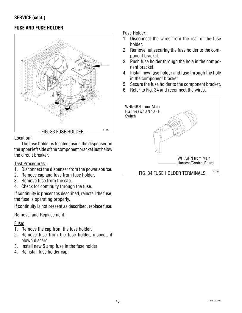
40
SERVICE (cont.)
FUSE AND FUSE HOLDER
R22
FIG. 33 FUSE HOLDER P1342
Location:The fuse holder is located inside the dispenser on
the upper left side of the component bracket just belowthe circuit breaker.
Test Procedures:1. Disconnect the dispenser from the power source.2. Remove cap and fuse from fuse holder.3. Remove fuse from the cap.4. Check for continuity through the fuse.If continuity is present as described, reinstall the fuse,the fuse is operating properly.If continuity is not present as described, replace fuse.
Removal and Replacement:
Fuse:1. Remove the cap from the fuse holder.2. Remove fuse from the fuse holder, inspect, if
blown discard.3. Install new 5 amp fuse in the fuse holder4. Reinstall fuse holder cap.
FIG. 34 FUSE HOLDER TERMINALS P1331
Fuse Holder:1. Disconnect the wires from the rear of the fuse
holder.2. Remove nut securing the fuse holder to the com-
ponent bracket.3. Push fuse holder through the hole in the compo-
nent bracket.4. Install new fuse holder and fuse through the hole
in the component bracket.5. Secure the fuse holder to the component bracket.6. Refer to Fig. 34 and reconnect the wires.
27646 022500
WHI/GRN from MainH a r n e s s / O N / O F FSwitch
WHI/GRN from MainHarness/Control Board

41
SERVICE (cont.)
ICE/OFF/NO ICE SWITCHES
FIG. 36 ICE/OFF/NO ICE SWITCH TERMINALSP1334
FIG. 35 ICE/OFF/NO ICE SWITCHES P1343
Location:The ICE/OFF/NO-ICE switches are located inside
the dispenser drawer.
Test Procedures:1. Disconnect the dispenser from the power source.2. Disconnect the black wire from the switch to be
tested and white/black from contactor located onthe outside bottom of the component bracket .
3. With a voltmeter, check the voltage across theblack wire and the white/black wire and all otherswitches in the down position (“ON”) to the centerof the control panel. Connect the dispenser to thepower source. The indication must be 5 volts dc.
4. Disconnect the dispenser from the power source.If voltage is present as described, reconnect the white/black wire to the contactor and proceed to #5.If voltage is not present as described, refer to the Wir-ing Diagram and check the dispenser wiring harness.5. Remove the white/yellow wire and the white/violet
wire from the right ICE/OFF/NO-ICE switch, thewhite/orange wire and the red/black from the leftICE/OFF/NO-ICE switch, or the brown/black wireand blue wire from the center ICE/OFF/NO-ICEswitch.
6. With the switch to be tested pressed down on theright side, check for continuity between the centerterminal and the left terminal. With the switchpressed down to the left, check for continuitybetween the center terminal and the right terminal.Continuity must not be present when neither sideof the switch is pressed down.
If continuity is present as described, the ICE/OFF/NO-ICE switch is operating properly.If continuity is not present as described, replace theICE/OFF/NO-ICE switch.
Removal and Replacement:1. Pull the dispenser drawer out until the drawer hits
the drawer stop. Using a screwdriver gently pry upon the drawer stop and remove the drawer fromthe dispenser.
2. Remove the four #8-32 locking screws securingthe switch panel to the drawer.
3. Lift switch panel with wires and L.E.D./adjustmentboard as an assembly.
4. Turn switch panel over and remove the wires fromthe ICE/OFF/NO-ICE switch that is to be replaced.
5. Compress the clips on the back of the control paneland gently push switch through the opening.
6. Push the new switch into the opening until theclips snap into position.
7. Reconnect the wires to the switch. Refer to Fig. 36when reconnecting wires.
8. Position the switch panel inside the drawer andsecure with four #8-32 locking screws.
27646 122200

42
SERVICE (cont.)
LAMP CORD ASSY
FIG. 37 LAMP CORD ASSY P1343
Location:The lamp cord assembly is located in the left top of
the auger motor cover.
Test Procedures:1. Disconnect the dispenser from the power source.2. Unplug the lamp cord assembly from lamp cord
connector assembly.3. Check for continuity across the tip of the cord
assembly and the housing. Continuity must not bepresent when both lamps are removed.
If continuity is present as described, the cord assem-bly is operating properly.If continuity is not present as described, replace thecord assembly.
Removal and Replacement:1. Disconnect the lamp cord assembly from the lamp
cord connector assembly in the top of the augermotor cover.
2. Remove the hopper cover with the lamp cordassembly from the hopper.
3. Remove hopper cover liner from the hopper cover.4. Cut the closed splice terminals connecting lamp
cord assembly to the lamp holder/socket assem-bly off.
5. Remove lamp cord assembly from hopper coverand discard.
6. Push new lamp cord wires through the holes onthe left outside top of the hopper cover.
7. Strip the wires from the lamp holder/socket as-sembly approximately .375”.
8. Using the two wire nuts, supplied, connect the newlamp cord assembly to the lamp holder/socketassembly wires.
9. Reinstall the hopper liner to the bottom of thehopper cover.
10. Reinstall the hopper cover to the hopper.11. Plug in the new lamp cord assembly to the lamp
cord connector assembly on left top of the augermotor cover.
12. Refer to Fig. 38 when reconnecting the wires.
FIG. 38 LAMP CORD WIRESP1332
27646 122200

43
SERVICE (cont.)
LAMP CORD CONNECTORIf continuity is not present when lamp cord assemblyis connected or continuity is present when lamp cordassembly is not connected, replace the lamp cordconnector.
Removal and Replacement:1. Disconnect the lamp cord assembly from the lamp
cord connector.2. Remove the two #8-32 locking screws securing
the auger motor cover the auger motor bracket/cooling drum bracket. Move cover back far enoughto gain access to the lamp cord connector.
3. Disconnect the lamp cord connector wires fromthe dispenser main wiring harness.
4. Remove nut and washer securing the lamp cordconnector to the auger motor cover and discardnut, washer and lamp cord connector.
5. Remove new nut and washer from new lamp cordconnector.
6. Push new lamp cord connector through the hole inthe auger motor cover and secure with the new nutand washer.
7. Reconnect the wires on the cord connector to thedispenser main wiring harness.
8. Position auger motor cover on auger motor bracket/cooling drum bracket and secure with two #8-32locking screws.
9. Refer to Fig. 40 when reconnecting wires.
FIG.40 LAMP CORD CONNECTOR P1323
FIG. 39 LAMP CORD CONNECTORP1343
Location:The lamp cord connectors are located inside the
upper left side of the auger covers.
Test Procedures:1. Disconnect the dispenser from the power source.2. Disconnect the plug on the dispenser main har-
ness from the connector from the lamp cordconnector.
3. With a voltmeter, check the voltage across the twopin holes on the main harness plug and DAY/NIGHT switch “-” in the down position and the ON/OFF switch in the “ON” position. Connect thedispenser to the power source. The indicationmust be approximately 12.6 volts dc.
4. Disconnect the dispenser from the power source.If voltage is present as described, proceed to #5.If voltage is not present as described, refer to theWiring Diagram and check the dispenser main wiringharness.NOTE: Lamp cord assembly (Fig. 37) and lamps, mustbe tested and determined to be functioning properlybefore proceeding to step 5.5. Check for continuity across the black wire pin and
red wire pin of the lamp cord connector (Fig. 40).Continuity must be present when the lamp cordassembly is connected and must not be presentwhen lamp cord assembly is disconnected fromlamp cord connector.
27646 122200
BLK to Main Wiring HarnessRED to Main Wiring Harness

44
Removal and Replacement:1. Disconnect the lamp cord assembly from the lamp
cord connector assembly in the top of the augermotor cover.
2. Remove the hopper cover with the lamp cordassembly from the hopper.
3. Remove hopper cover liner from the hopper cover.4. Cut off the closed-end splices connecting lamp cord
assembly to the lamp holder/socket assembly.5. Remove the two lamps.6. Remove the two #2-56 screws and elastic lock
nuts securing the lamp holder/socket assembly tothe mounting bracket. Remove lamp holder/socketassembly and discard.
7. Install new lamp holder/socket assembly on mount-ing bracket using two #2-56 screws and elasticlock nuts.
8. Reinstall lamps.9. Strip the wires from the lamp cord assembly
approximately .375”.10. Using the two wire nuts, supplied, connect the
lamp cord assembly to the new lamp holder/socket assembly wires.
11. Reinstall the hopper liner to the bottom of thehopper cover.
12. Reinstall the hopper cover to the hopper.13. Plug in the lamp cord assembly to the lamp cord
connector assembly on left top of the auger motorcover.
14. Refer to Fig. 42 when reconnecting the wires.
FIG. 42 LAMP HOLDER/SOCKET ASSEMBLYWIRES
P1322
SERVICE (cont.)
LAMP HOLDER/SOCKET ASSEMBLY
FIG. 41 LAMP HOLDER/SOCKET ASSEMBLYP1343
Location:The lamp holder/socket assemblies are located
inside the hopper covers.
Test Procedures:1. Disconnect the lamp cord assembly from the lamp
cord connector.2. Remove the lamps from the lamp holder/socket
assembly.3. With a voltmeter, check the voltage across the pin
sockets in the plugs with the DAY/NIGHT switch inthe “-” down position and ON/OFF switch in the“ON” position. Reconnect the lamp cord to thelamp cord connector. The indication must beapproximately 12.6 volts dc.
4. Disconnect the lamp cord from the lamp cordconnector.
If voltage is present as described, the lamp holder/socket assembly is operating properly.If voltage is not present as described, replace the lampholder/socket assembly.5. Check for continuity across the terminals on the
lamps.If continuity is present as described, the lamps areoperating properly.If continuity is not present as described, replace thelamp.
27646 122200

45
SERVICE (cont.)
L.E.D./ADJUSTMENT BOARD3. Lift switch panel with wires and L.E.D. /adjustment
board as an assembly and turn over.4. Disconnect the connector on the dispenser wiring
harness from the pin connector on the rear of theL.E.D./adjustment board.
5. Remove the #4 keps nut from the right rear stud onthe control panel and remove the green groundwire.
6. Remove the remaining five #4 keps nuts from thestuds on the control panel.
7. Remove the #6 stainless steel washer and the #6nylon washer from the front stud on the controlpanel.
8. Remove board and discard.9. Position a new board on the studs and spacers.10. Install the #6 nylon washer and the #6 stainless
steel washer on the front stud of the control panel.Be sure the nylon washer is installed first.
11. Secure the new board to the control panel usingfive #4 keps nuts.
12. Connect the green lead from the dispenser mainharness to the right rear stud of the control paneland secure with a #4 keps nut.
13. Reconnect the connector from the dispenser mainwiring harness to the pin connector at the rear ofnew L.E.D./adjustment board.
14. Turn board and panel over and position in thedispenser drawer and secure with four #8-32locking screws.
FIG. 43 L.E.D./ ADJUSTMENT BOARD P1343
Location:The L.E.D./adjustment board is located in the
dispenser drawer attached to the bottom of the controlpanel.
Test Procedures:1. Disconnect the dispenser from the power source.2. Disconnect the connector at the rear of the L.E.D./
adjustment board from the dispenser main wiringharness.
3. With a voltmeter, check the voltage between pinhole #1 (black wire) and pin hole #8 (pink wire)with the ON/OFF switch in the “ON” position.Connect the dispenser to the power source. Theindication must be 5 volts dc.
4. Disconnect the dispenser from the power source.If voltage is present as described, replace the L.E.D./adjustment board.If voltage is not present as described, refer to theWiring Diagram and check the dispenser wiring har-ness.
Removal and Replacement:1. Pull the dispenser drawer out far enough to expose
the four #8 -32 locking screws securing the switchpanel to the drawer.
2. Remove the four #8-32 locking screws.
27646 122200

46
FIG.45 SOLENOID TERMINALS P1327
SERVICE (cont.)
SOLENOIDS
R22
FIG. 44 SOLENOIDS P1342
Location:The solenoids are mounted on a bracket that is
attached on top of the chassis on the left side.
Test Procedures:1. Disconnect the dispenser from the power source.2. Disconnect the white/black wire from the solenoid
to be tested and the orange wire from the leftsolenoid, the violet wire from the right solenoid orthe white/violet wire from the center solenoid.
3. With a voltmeter, check the voltage across thewhite/black wire and the other wire with the ON/OFF switch in the “ON” position and the appropri-ate ICE/OFF/NO-ICE switch in the “ICE” or “NO-ICE” position. Connect the dispenser to the powersource. The indication must be:a) 120 volts ac for 120 volt models.b) 230 volts ac for 230 volt models.
4. Disconnect the dispenser from the power source.If voltage is present as described, proceed to #5If voltage is not present as described, refer to the WiringDiagram and check the dispenser main wiring harness.5. Check for continuity across the solenoid valve coil
terminals.If continuity is present as described, reconnect thewires to the solenoid.If continuity is not present as described, replace thesolenoids.6. Check the solenoid valve for coil action. Connect
the dispenser to the power source. With the augermotor switch in the “ON” position and the ON/OFF/ICE switch in the “ICE” or “NO-ICE” position pressthe ON/OFF switch to the “ON” position. Afterapproximately two minutes listen carefully in thevicinity of the solenoid valve for a “clicking” soundas the coil magnet attracts.
7. Disconnect the dispenser from the power source.If the sound is heard as described and the refrigerantwill not pass through the solenoid valve, there maybe a blockage in the refrigerant line before the sole-noid valve, or the solenoid valve may require inspec-tion for wear, and removal of particles.If the sound is not heard as described, replace thesolenoids.
Removal and Replacement:NOTE: Before removal of any refrigeration componentthe refrigerant in the system must be reclaimed by alicensed refrigeration repair person.1. Disconnect the wires from both solenoids.2. Disconnect the refrigerant lines from the sole-
noids to the cooling drums and the refrigerant linefrom the accumulator.
3. Remove the #6 hex crimptite securing solenoidbracket to the dispenser chassis.
4. Remove bracket and solenoids from the chassisassembly.
5. Remove the four #8-32 locking screws securingthe solenoids to the bracket.
6. Remove solenoid and repair or discard.7. Install new solenoid on mounting bracket using
four #8-32 locking screws.8. Reinstall mounting bracket and solenoids inside
the dispenser chassis, securing with a #6 hexcrimptite screw.
9. Reconnect the tubes from the accumulator and thecooling drums.
10. Refer to Fig. 45 and reconnect the wires.11. Evacuate the system.12. Recharge the system with the appropriate coolant
and to the pressures directed on the decalsNOTE: The charging of the system must be done by alicensed refrigeration repair person.
27646 122200

47
FIG. 47 TEMPERATURE SENSORP1325
SERVICE (cont.)
TEMPERATURE SENSOR
FIG. 46 TEMPERATURE SENSORP1341
Location:The temperature sensors are located inside the top
rear of the cooling drum under the auger motorcovers.
Test Procedures:1. Position the DAY/NIGHT switch in the “NIGHT”
position, check the L.E.D. on the control panel forflashes.
2. The L.E.D. for the temperature sensor is locatedbetween the appropriate auger switch and the iceswitch.
3. If the temperature in the cooling drum is less than20° F (-6˚C) or more than 120°F (73˚C) for 10seconds the L.E.D. will flash twice every fourseconds.
4. If flashing is present as described, replace thetemperature sensor.
NOTE: Auger motor cover must be in place to give acorrect reading.
Removal and Replacement:1. Remove the two #8-32 securing the auger motor
cover to cooling drum mount and remove thecover. Set aside for reassembly.
2. Disconnect the plug on the temperature sensorleads from the connector on the dispenser mainwiring harness.
3. Pull the temperature sensor from the tube at thetop rear of the cooling drum and discard.
4. Push new temperature sensor into the tube at thetop rear of the cooling drum as far as it will go.
5. Refer to Fig. 47 and reconnect the wires.6. Position auger motor cover on cooling drum mount
and secure with two #8-32 locking screws.
27646 122200

48
FIG. 49 TORQUE SENSOR CIRCUITBOARD TERMINALS
P1328
SERVICE (cont.)
TORQUE SENSOR CIRCUIT BOARD
FIG. 48 TORQUE SENSOR CIRCUIT BOARDP1341
Location:The torque sensor circuit board is located on the
rear of the cooling drum mount just left of center.
Test Procedures:1. With the ON/OFF switch and Auger switch in the
“ON” position and the ICE/OFF/NO-ICE switch inthe “ICE” position check the L.E.D. on the controlpanel.
2. The L.E.D. for the torque sensor is located be-tween the appropriate auger switch and the iceswitch.
3. If the L.E.D. flashes one time every four secondsthe auger is not turning. If the L.E.D. flashes threetimes every four seconds the torque is less thanpossible. If the L.E.D. flashes four times every fourseconds the torque is greater than possible.
4. If the L.E.D. flashes three times every four sec-onds, four times every four seconds or one timeevery four seconds with the auger turning, replacethe torque sensor circuit board.
Removal and Replacement:1. Remove the two #8-32 locking screws securing
the auger motor cover to the cooling drum mount.2. Remove the cover and set aside for reassembly.3. Remove the #8 locking screw on the lower right
side of the auger motor mounting bracket secur-ing the auger motor run capacitor. Set capacitoraside with wires attached.
4. Disconnect the auger motor plug from the connec-tor on the main wiring harness.
5. Remove the three remaining #8 locking screwssecuring the auger motor mounting bracket tocooling drum mounting bracket.
6. Remove motor with mounting bracket, drip tray,split pin and torsion spring bearings as an assem-bly and set aside for reassembly.
NOTE: When removing or installing the motor be surethe split pin in the motor shaft is turned to a positionthat will clear the torque sensor circuit board.7. Disconnect the plug from the dispenser main
wiring harness to the torque sensor circuit board.8. Remove the #8-32 locking screw and washer
securing torque sensor circuit board to the coolingdrum mount.
9. Remove torque sensor circuit board and discard.10. Install new torque sensor circuit board in the slot
in the rear of the cooling drum mount and securewith a #8-32 locking screw and washer.
11. Refer to Fig. 49 and reconnect the wires.12. Reinstall motor with mounting bracket, drip tray,
split pin and torsion spring bearings using three#8 locking screws onto the cooling drum bracket.
13. Install the auger motor capacitor on the lower rightside of the auger mounting bracket using theremaining #8 locking screw.
14. Connect the auger motor terminal to the terminalon the main wiring harness.
15. Refer to Fig. 49 when reconnecting the wires.16. Position the auger motor cover on the cooling drum
mount and secure with two #8-32 locking screws.
27646 122200

49
SERVICE (cont.)
TRANSFORMER
FIG. 51 TRANSFORMER TERMINALS P1329
R22
FIG. 50 TRANSFORMER P1342
Location:The transformer is located inside the chassis on
the upper rear side of the component bracket.
Test Procedures:1. Disconnect the dispenser from the power source.2. Disconnect the plug from the transformer to the
connector from the dispenser main wiring har-ness.
3. With a voltmeter, check the voltage across thewhite/red wire and the white/black wire in thedispenser main wiring harness connector. Con-nect the dispenser to the power source. The indi-cation must be:a) 120 volts ac for 120 volt models.b) 230 volts ac for 230 volt models.
4. Disconnect the dispenser from the power source.If voltage is present as described, proceed to #5.If voltage is not present as described, refer to theWiring Diagram and check the dispenser main wiringharness.5. Reconnect the plug from the transformer to the
connector from the dispenser main wiring har-ness.
6. Connect the dispenser to the power source.7. Disconnect the lamp cord from the lamp cord
connector.
8. With a voltmeter, check the voltage across theinside of lamp cord socket and the outside with theDAY/NIGHT switch in the “-” down position. Theindication must be approximately 12.6 volts dc.
9. Disconnect the dispenser from the power source.If voltage is present as described, the transformer isoperating properly.If voltage is not present as described, replace the trans-former.
Removal and Replacement:1. Remove the four #8-32 locking screws securing
the component bracket to the chassis.2. Pull component bracket from the chassis far
enough to gain access to the transformer.3. Disconnect the connector from the dispenser main
wiring harness from the plug on the transformer.4. Remove the four #8-32 locking screws securing
the transformer to the component bracket.5. Remove transformer and discard,6. Position new transformer on the component
bracket and secure with four #8-32 locking screws.7. Reconnect the plug on the transformer to the
connector on the dispenser wiring harness.8. Refer to Fig. 51 and reconnect the wires.9. Position component bracket in the chassis and
secure with four #8-32 locking screws.
27646 122200

50
SERVICE (CONT.)
VOLTAGE DIVIDER (PAF Models only)
Location:The voltage divider is located in the wiring har-
ness, inside the chassis near the upper rear side of thecomponent bracket.
Test proceedures:1. Disconnect the dispenser from the power source.2. Disconnect the four-pin plug of the main harness
from the four-pin plug on the voltage divider.3. With a voltmeter, check voltage across the white/
red wire (pin 1) and the white/black wire (pin 2) atthe plug on the main wiring harness. Connect thedispenser to the power source; set the mainpower switch to “ON” position; set the DAY/NIGHT switch to “DAY” position. The indicationmust be:a) 120 volts ac for 120 volt 2 wire models.b) 230 volts ac for 230 volt 2 wire models.
4. Disconnect the dispenser from the power source.
If voltage is present as described, reconnect the plugand connector and proceed to step 5.If voltage is not present as described, refer to theWiring Diagrams and check the main wiring harness.
27646 122200
FIG. 52 VOLTAGE DIVIDERP2268
5. With a voltmeter, check voltage between J4 pin 3and J4 pin 23 of the control board. Connect thedispenser to the power source; set the main powerswitch to “ON” position; set the DAY/NIGHT switchto “DAY” position. The indication must be 12 voltsac.
If voltage is present as described, the voltage divideris operating properly.If voltage is not present as described, replace thevoltage divider.

51
COOLANT SCHEMATIC DIAGRAM CDS-2
27646 022500

52
COOLANT SCHEMATIC DIAGRAM CDS-3(Prior to S/N CDS 0019500)
LEF
T E
VA
PO
RAT
OR
CE
NT
ER
EV
AP
OR
ATO
R
CO
ND
EN
SE
R
SU
CT
ION
AC
CU
MU
LATO
R
CO
MP
RE
SS
OR
RIG
HT
EV
AP
OR
ATO
R
SP
LIT
TE
RF
ILT
ER
DR
YE
R
ss
sAE
V
AE
VA
EV
HO
T G
AS
BY-
PAS
S V
ALV
E
SO
LEN
OID
27646 022500

53
LEF
T E
VA
PO
RAT
OR
CE
NT
ER
EV
AP
OR
ATO
R
CO
ND
EN
SE
R
SU
CT
ION
AC
CU
MU
LATO
R
CO
MP
RE
SS
OR
RIG
HT
EV
AP
OR
ATO
R
SP
LIT
TE
RF
ILT
ER
DR
YE
R
s
TE
V
TE
VT
EV
ss
SIG
HT
GLA
SS
COOLANT SCHEMATIC DIAGRAM CDS-3(S/N CDS 0019500 - Up)
27646 022500

54 27646 022500

55 27646 022500

56 27646 022500

57 27646 022801
WHI/BRNor VIO
WHI/REDWHI/RED
WHI/BLU
WHI/BLU
LT. AUGER SW.
RT. AUGER SW.
WHI/BRN
RIGHTAUGER
BLKREDWHI
BLK
BLK
WHI/BLKLEFT
AUGER
BLKREDWHI
WHI/BLK
1
4
WHI/BLKBLK
WHI/BLKREDWHI/BLK
RED-22BLK-22
1
4
SOL
LEFT
ORA-22
WHI/GRN
SCHEMATIC WIRING DIAGRAM FOR CDSA-2 PAF
WHI/GRN WHI/GRNON/OFF SW.
27556.0003B 02/01 © 1996 BUNN-O-MATIC CORPORATION
230 VOLTS AC2 WIRE
SINGLE PHASE50 HZ
J4-1
J4-24
CONTROL
BOARD
J4-5
J4-10
J4-15
J4-20
YEL-22VIO-22RED-22BLK-22
GRY-22BLU-22RED-22GRN-22ORA-22BLK-22PNK-22RED/BLKWHI/ORA
WHI/GRN-22WHI/VIOWHI/YEL
WHI/VIO-22YEL
BRN/BLKVIOORA
WHI/BLKWHI/GRN
RED
WHI/GRN
DAY/NIGHT SW.
WHI/GRN
5 AMP
WHI/BLK WHI/BLK
BLK-22RED-22VIO-22
YEL-22
GRN-22PNK-22
1
5
9
ADJUSTMENT
BOARD
WHI/GRN
SOL
RIGHT
BLKt°
1BLK
LEFT
RIGHTBLKt°
1BLK
WHI/BLK
WHI/GRN-22
WHI/VIO-22
BLK-22
WHI/BLK
WHI/BLKICE/OFF/NO-ICESWITCHES
WHI/BLK
WHI/BLK
FAN
PNK-221 LEFT
TORQUESENSOR
BLU-22
BLK-22PNK-22
1 RIGHTTORQUESENSOR
GRY-22
BLK-22
BLK-22
BLK-22 BLK-22
RIGHTLEFT
PNK-22
1
4
BLKBLKK1-6K1-8
K1 10
LIMITTHERMOSTAT
WHI/REDBLK
WHI/BLKWHI/BLK
5 4 3 2 1
DAY/NIGHTTIMER
M
M
VoltageDivider
COMPRESSOR ASSEMBLY
WHI/RED
WHI/BLKWHI/RED
RIGHT SPRINGCONTACT
LEFT SPRINGCONTACT
GRNGRN GRNGRN
WHI/RED
GRNGRN
WHI/REDWHI/BLK
WHI/RED
BLU
WHI
GRN/YEL L2L1
BRN
BLKEMI
FILTER
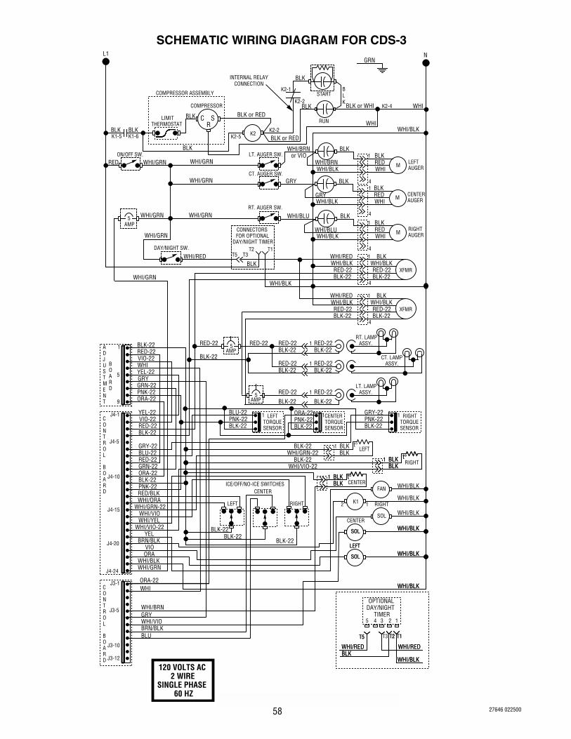
58 27646 022500
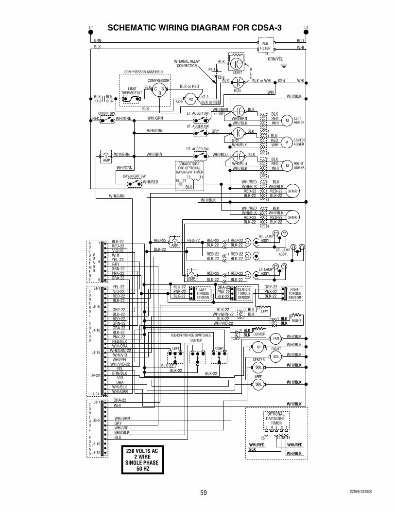
59 27646 022500

60 27646 022500


