
119 Series Fuel Gas Valve
IntroductionThe 119 Series fuel gas valve (Figure 1) is used for on-off or throttling control of non-corrosive or mildly corrosive flow media. It is designed to meet low-pressure application requirements in many varied industries.
Features • Easy Installation—Compact, lightweight
construction permits easy handling and installation. • Easy Leak Detection—Vent hole between body
and actuator stem seals allows detection of body or actuator seal leakage.
• Easily Adjusted Spring—The 119 Series spring is adjusted by rotating the adjusting screw on the top of the spring case.
• Easy Maintenance—The fuel gas valve can be completely disassembled without removing the valve body from the line.
• Low Leakage—The composition disk assembly provides positive shutoff, minimizing seat leakage when downstream demand is zero.
• Sour Gas Service Capability—Optional materials are available for applications handling sour gases. These constructions comply with the recommendations of NACE International MR0175-2002 and NACE MR0175/ISO 15156.
• Variable Opening Speed—The Types 119EZ and 119EZS come with a variable restrictor that allows for tuning of valve opening speed.
Figure 1. 119 Series Fuel Gas Valve
TypE 119 TypE 119EZ
Bulletin 71.1D100006X012
November 2017
119 Series

1. The pressure/temperature limits in this Bulletin, ASCO™ solenoid documentation and any applicable standard or code limitation should not be exceeded.2. Pressure and/or the body end connection may decrease these maximum temperatures.3. Not for use with hot water or Ammonia (NH3).4. Minimum temperature for Cast Iron body is -20°F / -29°C.
SpecificationsThe Specifications table lists the specifications for the 119 Series fuel gas valve. Some of the specifications of the given valve that originally comes from the factory, are stamped on the nameplate located on the spring case flange.
Available Configuration Type 119: Direct-operated valve used for on-
off or throttling control of noncorrosive or mildly corrosive liquids and gases
Type 119EZ: Direct-operated valve with adjustable opening speed for reliable startup operation on gas burner systems
Type 119EZS: Type 119EZ equipped with solenoid for valve to be operated by local control system
Body Sizes and End Connection Styles Type 119:
BODy SIZE,NPT BODy MATErIAL
3/4
Cast Iron, WCC steel1
1-1/4
Types 119EZ and 119EZS:BODy SIZE,
NPT BODy MATErIAL
1 CF8M Stainless steel, Cast Iron
Spring ranges See Table 1Orifice Size and Flow Coefficients See Table 2Maximum Inlet pressure(1)
150 psig / 10.3 barMaximum Control pressure to Diaphragm 150 psig / 10.3 barMaximum pressure Drop(1)
150 psig / 10.3 bar for all port diameters 115 psig / 7.9 bar for Type 119EZS with
ASCO™ 8320 Series solenoidpressure Setting Adjustment May be adjusted throughout each spring range
by rotating the adjusting screwType 119EZS Solenoid Specifications Electric Train: Refer to ASCO™ 8320 Series
General Service Solenoid Valve Catalog (Document Number: 8320R2)
Low Power/Solar: Refer to ASCO™ Low Power Solutions Catalog (Document Number: V7704)
Valve plug Travel 3/16 in. / 4.8 mmActuator Control Line Connection 1/4 FNPT
Spring Case and Bonnet Vents 1/4 FNPTFlow Direction Up through the orificeMaterial Temperature Capabilities(1)(2)
Type 119:MATErIAL TEMpErATurE rAnGE
Nitrile (NBR) -20 to 180°F / -29 to 82°C
Fluorocarbon (FKM)(3) 0 to 250°F / -18 to 121°C
Types 119EZ and 119EZS:MATErIAL TEMpErATurE rAnGE
Nitrile (NBR)(4) -40 to 180°F / -40 to 82°C
Fluorocarbon (FKM)(3) 0 to 250°F / -18 to 121°C
Type 119EZS Solenoid Temperature Capabilities(1)
ASCO™ 8320 Series Solenoid: 32 to 125°F / 0 to 52°C ASCO™ 8314 Series Solenoid: -13 to 131°F / -25 to 55°CConstruction Materials Standard Construction Valve Body: Cast iron, WCC steel or
Stainless steel Spring Case: Aluminum Bonnet: Aluminum Disk Holder Assembly: Aluminum and Nitrile (NBR) (standard), Stainless steel and Nitrile (NBR) or Stainless steel and Fluorocarbon (FKM) Orifice: Aluminum (standard) or Stainless steel Diaphragm: Nitrile (NBR) or Fluorocarbon (FKM) O-rings: Nitrile (NBR) (standard) or
Fluorocarbon (FKM) Stem Wiper: Polytetrafluoroethylene (PTFE) Adjusting Screw: Steel Spring: Steel nACE Construction Body: Steel or Stainless steel Disk Holder Assembly: Aluminum or
Fluorocarbon (FKM) Diaphragm and Stem Assembly: Aluminum or Fluorocarbon (FKM) O-rings and Internal Retaining Rings: Fluorocarbon (FKM)Approximate Weight 6 lbs / 3 kg
2
119 Series

Figure 2. 119 Series Operational Schematics
TypE 119
Figure 3. Burner Management Operational Schematics
LPSD#1
START STOP ACK.
CONFIGPAGE
SCROLLEXIT
SELECTITEMCALIB.
PASSWORDREQUIRED
OPERATORACCESSIBLE
HPSD#1
*
* Optional
S
S
S
S
INLET PRESSUREMEDIUM / LOW PRESSURELOADING PRESSURE
FuEL GAS
627 SErIES
67C SErIES
BurnEr MAnAGEMEnT
67CSErIES
YS
SOLEnOID VALVE
EMErGEnCy SHuTDOWn
VALVE
MAIn BurnEr
pILOT BurnEr
MAIn BurnEr VALVE
pILOT BurnEr rEGuLATOr
pILOT SOLEnOID VALVE
SOLEnOID VALVE
MAIn BurnEr
rEGuLATOr
Type 119
M10
33
July 2007 Type 119
119EZ SErIES
TypE 119
LOADInG prESSurE rEGuLATOr
M1033
INLET PRESSUREOUTLET PRESSURE
ATMOSPHERIC PRESSURE
LOADING PRESSURE
TypE 119EZ(1)
M1266
1. Solenoid valve connects to loading pressure port.
INLET PRESSUREOUTLET PRESSURE
ATMOSPHERIC PRESSURE
LOADING PRESSURE
LPSD#1
START STOP ACK.
CONFIGPAGE
SCROLLEXIT
SELECTITEMCALIB.
PASSWORDREQUIRED
OPERATORACCESSIBLE
HPSD#1
*
* Optional
S
S
S
S
INLET PRESSURE
MEDIUM / LOW PRESSURE
LOADING PRESSURE
p2101_1
*Optional
3
119 Series
principle Of Operation
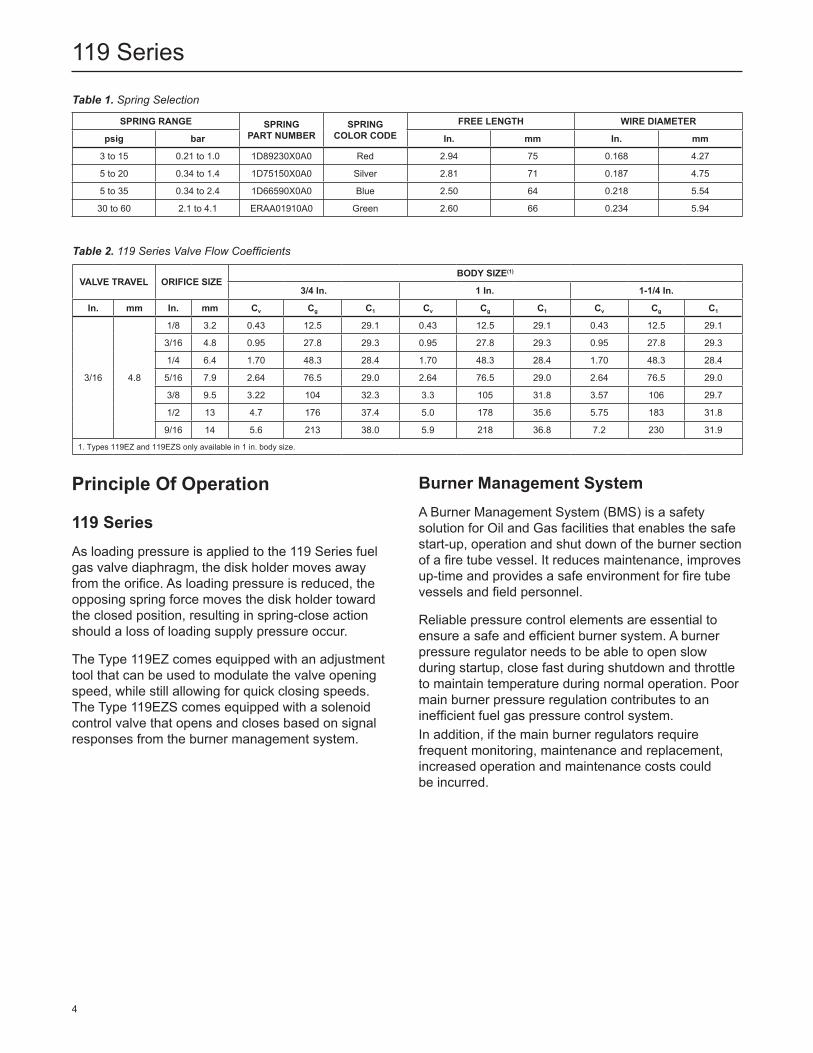
119 SeriesAs loading pressure is applied to the 119 Series fuel gas valve diaphragm, the disk holder moves away from the orifice. As loading pressure is reduced, the opposing spring force moves the disk holder toward the closed position, resulting in spring-close action should a loss of loading supply pressure occur.
The Type 119EZ comes equipped with an adjustment tool that can be used to modulate the valve opening speed, while still allowing for quick closing speeds. The Type 119EZS comes equipped with a solenoid control valve that opens and closes based on signal responses from the burner management system.
SprInG rAnGE SprInG pArT nuMBEr
SprInG COLOr CODE
FrEE LEnGTH WIrE DIAMETEr
psig bar In. mm In. mm
3 to 15 0.21 to 1.0 1D89230X0A0 Red 2.94 75 0.168 4.27
5 to 20 0.34 to 1.4 1D75150X0A0 Silver 2.81 71 0.187 4.75
5 to 35 0.34 to 2.4 1D66590X0A0 Blue 2.50 64 0.218 5.54
30 to 60 2.1 to 4.1 ERAA01910A0 Green 2.60 66 0.234 5.94
Table 1. Spring Selection
VALVE TrAVEL OrIFICE SIZEBODy SIZE(1)
3/4 In. 1 In. 1-1/4 In.
In. mm In. mm Cv Cg C1 Cv Cg C1 Cv Cg C1
3/16 4.8
1/8 3.2 0.43 12.5 29.1 0.43 12.5 29.1 0.43 12.5 29.1
3/16 4.8 0.95 27.8 29.3 0.95 27.8 29.3 0.95 27.8 29.3
1/4 6.4 1.70 48.3 28.4 1.70 48.3 28.4 1.70 48.3 28.4
5/16 7.9 2.64 76.5 29.0 2.64 76.5 29.0 2.64 76.5 29.0
3/8 9.5 3.22 104 32.3 3.3 105 31.8 3.57 106 29.7
1/2 13 4.7 176 37.4 5.0 178 35.6 5.75 183 31.8
9/16 14 5.6 213 38.0 5.9 218 36.8 7.2 230 31.9
1. Types 119EZ and 119EZS only available in 1 in. body size.
Table 2. 119 Series Valve Flow Coefficients
Burner Management SystemA Burner Management System (BMS) is a safety solution for Oil and Gas facilities that enables the safe start-up, operation and shut down of the burner section of a fire tube vessel. It reduces maintenance, improves up-time and provides a safe environment for fire tube vessels and field personnel.
Reliable pressure control elements are essential to ensure a safe and efficient burner system. A burner pressure regulator needs to be able to open slow during startup, close fast during shutdown and throttle to maintain temperature during normal operation. Poor main burner pressure regulation contributes to an inefficient fuel gas pressure control system. In addition, if the main burner regulators require frequent monitoring, maintenance and replacement, increased operation and maintenance costs could be incurred.
4
119 Series

Emerson simplifies the complexity of fuel gas pressure control system by providing a one-stop solution, eliminating procurement challenges. Emerson’s solution works with a BMS to ensure efficient burner ignition/re-ignition, shutdown and steadily throttles to maintain temperature during normal operation. The solution is proven and robust, thereby significantly lowering maintenance expenses.
InstallationThe 119 Series may be installed in any position, but normally the actuator is vertical above the valve body. Install the valve body such that the direction of the process flow matches the flow direction arrow on the side of the body.
Each fuel gas valve has a screened vent in the spring case and in the valve bonnet. On indoor installations, these vents should be piped outdoors with the shortest, straightest pipe of the largest practical diameter. For both indoor and outdoor installation the vents or vent pipe must be protected from debris, weather, condensation, or anything else that might clog it.
Overall dimensions are shown in Figure 4.
nACE ComplianceOptional materials are available for applications handling sour gases. These constructions comply with the recommendations of NACE International sour service standards.
The manufacturing processes and materials used by Emerson assure that all products specified for sour gas service comply with the chemical, physical, and metallurgical requirements of NACE MR0175-2002 and/or NACE MR0175/ISO 15156. Customers have the responsibility to specify correct materials. Environmental limitations may apply and shall be determined by the user.
Capacity Information
Air CapacitiesTo determine wide-open flow capacity for fuel gas valve sizing, use one of the following equations:
For Critical Pressure Drops
Use this equation for critical pressure drops (absolute outlet pressure equal to one-half or less than one-half the absolute inlet pressure).
Q = P1(abs)Cg
where, Q = gas flow rate, SCFH Cg = gas sizing coefficient P1 = absolute inlet pressure, psia
For Non-Critical Pressure Drops
Use this equation for pressure drops lower than critical (absolute outlet pressure greater than one-half of absolute inlet pressure).
Q = CgP1SIN DEG520GT
3417C1
ΔPP1
where,
Q = gas flow rate, SCFH G = specific gravity of the gas T = absolute temperature of gas
at inlet, °Rankine Cg = gas sizing coefficient P1 = absolute inlet pressure, psia C1 = flow coefficient ΔP = pressure drop across the regulator, psi
Then, if capacity is desired in normal cubic meters per hour at 0°C and 1.01325 bar, multiply SCFH by 0.0268.
5
119 Series

Liquid Capacities (for Type 119 only)
To determine regulating capacities or to determine wide-open capacities for relief sizing at any inlet pressure, use the following equation.
Q = CvΔPG
where, Q = liquid flow rate, GPM ΔP = pressure drop across the regulator, psi CV = regulating or wide-open flow coefficient G = specific gravity of the liquid
Ordering InformationUse the Specifications section on page 2 and carefully review the description to the right of each specification. Use this information to complete the Ordering Guide on this page. Specify the desired selection wherever there is a choice to be made. Then send the Ordering Guide to your local Sales Office.
Ordering GuideType (Select One) 119 119EZ 119EZSBody Size and Material (Select One) 3/4 npT (Available for Type 119 only) Cast iron WCC Steel 1 NPT Cast iron WCC Steel Stainless Steel (available for Type 119EZ only) 1-1/4 npT (Available for Type 119 only) Cast iron
Spring ranges 3 to 15 psig / 0.21 to 1.0 bar, Red 5 to 20 psig / 0.34 to 1.4 bar, Silver 5 to 35 psig / 0.34 to 2.4 bar, Blue 30 to 60 psig / 2.1 to 4.1 bar, GreenOrifice Size 1/8 in. / 3.2 mm 3/16 in. / 4.8 mm 1/4 in. / 6.4 mm 5/16 in. / 7.9 mm 3/8 in. / 9.5 mm 1/2 in. / 13 mm 9/16 in. / 14 mmnACE Standard Mr0175-2002 Construction YesnACE Mr0175/ISO 15156 Construction (for Type 119EZ only) Yesreplacement parts Kit (Optional) Yes, send one replacement parts kit to match
this order.
6
119 Series

Figure 4. Dimensions
A2952-1
In. /mm
4.12 /105
8.00 / 203
MAXIMuM
1.53 /39
2.12 /54
4.00 /102
3/4, 1, Or 1-1/4 npT
TypE 119
TypE 119EZS
1.59 / 40.4
3.7 / 95
Ø1.4 / 37
8.00 / 203MAXIMUM
2 / 50
2.25 / 57.2
4.12 / 104.6
7 / 178
5.7 / 145
NPT
ErAA20310_AA
7
119 Series
119 Series
Facebook.com/EmersonAutomationSolutions
LinkedIn.com/company/emerson-automation-solutions
Twitter.com/emr_automation
Fisher.com
D100006X012 © 1990, 2017 Emerson Process Management Regulator Technologies, Inc. All rights reserved. 11/17. The Emerson logo is a trademark and service mark of Emerson Electric Co. All other marks are the property of their prospective owners. Fisher™ is a mark owned by Fisher Controls International LLC, a business of Emerson Automation Solutions.
The contents of this publication are presented for information purposes only, and while effort has been made to ensure their accuracy, they are not to be construed as warranties or guarantees, express or implied, regarding the products or services described herein or their use or applicability. All sales are governed by our terms and conditions, which are available on request. We reserve the right to modify or improve the designs or specifications of our products at any time without notice.
Emerson Process Management Regulator Technologies, Inc. does not assume responsibility for the selection, use or maintenance of any product. Responsibility for proper selection, use and maintenance of any Emerson Process Management Regulator Technologies, Inc. product remains solely with the purchaser.
Emerson Automation Solutions
Americas McKinney, Texas 75070 USA T +1 800 558 5853
+1 972 548 3574
Europe Bologna 40013, Italy T +39 051 419 0611
Asia Pacific Singapore 128461, Singapore T +65 6770 8337
Middle East and Africa Dubai, United Arab Emirates T +971 4 811 8100


