
Building a project ontology with extreme collaboration and virtual
design and construction
Ana Cristina Bicharra Garcia*, John Kunz, Martin Ekstrom, Arto Kiviniemi
CIFE-Stanford University, Rua Nascimento Silva, Ana Cristina Bicharra Garcia, Rio de Janeiro 22421-020, Brazil
Abstract
This paper defines the concept of the ‘tripod’ method of design that uses VDC modeling (multi-disciplinary performance-based virtual
design and construction modeling), an integrated POP model (a formal and integrated model of Product, Organization and Process of the
project) and Extreme Collaboration (a very rapid concurrent and technologically enabled social process of design). The paper focuses in
particular on the generic ontology of the POP model, which specifies the related functional requirements, designed forms and predicted,
observed and desired behaviors of the defined POP elements. With collateral drawings, models, analyses and explanations, the project
specific POP model becomes the schematic and initial detailed design for the project. We describe use of the tripod method for the
preliminary design of a large commercial building project. While large generic building project ontologies exist, e.g. the Industry Foundation
Classes, we find that our ontology is so simple that teams using any design tools and methods can use it today, and it is helpful. We interpret
our results as early evidence that the Tripod engineering process of VDC, Extreme Collaboration and use of a generic POP ontology together
enable a design team to build a new integrated multidisciplinary project design model very rapidly. It can then be used to support downstream
detailed design and construction planning and also reuse in other engineering projects.
q 2004 Elsevier Ltd. All rights reserved.
Keywords: Tripod engineering process model; POP ontology; VDC; Virtual design and construction; XC; Extreme collaboration
147
doi
*
stan
arto
Alle guten Dinge sind drei
(All good things come in threes)
German proverb
1. Introduction
A 19th century engineer could grasp his discipline in its
totality. Today, engineering has many subdisciplines, each
with a set of experts looking at the same problem with a
different approach, and no individual can master all the
details of a project. Specialization has both allowed us to
push the frontier in many directions and has led us to the
subdivision of design project into separate activities, each
managed by one or more experts. The performance of
4-0346/$ - see front matter q 2004 Elsevier Ltd. All rights reserved.
:10.1016/j.aei.2004.09.001
Corresponding author. Tel.: C55 21 26295675.
E-mail addresses: [email protected] (A.C.B. Garcia), kunz@
ford.edu (J. Kunz), [email protected] (M. Ekstrom),
[email protected] (A. Kiviniemi).
a design project is, therefore, not only a function of the
expertise of the individual experts, but also how well they
work together. If each task is independent, or if the
information flows only in one direction, the individual
activities can be sequentially executed at the experts’ own
place of work. However, as the project’s tasks get more
interdependent, more interaction in terms of communication
and coordination is required among the project team
participants.
Depending on the type of task interdependence, syn-
chronous or asynchronous communication will be more
efficient [15] for project development. In particular,
reciprocally dependent tasks require synchronous com-
munication, i.e. face-to face meetings. As the number of
these tasks increases, more meetings are required to avoid
misunderstandings and misconceptions that lead to rework.
The NASA Jet Propulsion Laboratory (JPL) pioneered
Extreme Collaboration (XC) as a project development
method to design projects very rapidly, in spite of the
problem that many tasks are complex and have high
reciprocal interdependence [14]. XC features include
Advanced Engineering Informatics 18 (2004) 71–83
www.elsevier.com/locate/aei

A.C.B. Garcia et al. / Advanced Engineering Informatics 18 (2004) 71–8372
collocation of design team participants, use of multiple high
performance descriptive and predictive engineering models
and excellent shared visualization on multiple projected
computer screens. XC gives a structured, fast and effective
way to discuss, analyze, and explain highly interdependent
tasks. The XC goal is to create and document a technical
project solution for a particular problem specification
quickly, normally in about a week rather than in the usual
6–12 months that is typical of engineering projects.
According to Mark, XC diminishes rework by reducing
misconceptions and misunderstanding caused by asynchro-
nous communication difficulties. Everybody is available for
providing data, analysis, decisions, explanation and sugges-
tions. XC requires that work organized as synchronous
meetings vs. distributed and asynchronous tasks.
The method of Virtual Design and Construction (VDC) is
the use of multi-disciplinary performance models of design-
construction projects, including the Product (i.e. facilities),
Work Processes, Organization of the design—construc-
tion—operation team, and Economic Impact (i.e. model of
both cost and value of capital investments) in order to
support business objectives [9]. The Virtual Design and
Construction (VDC) approach defines Project models as the
composition of related models of Product, Organization and
Process (POP). We suggest that developing and modeling
the Product, Organization and Process consistently and in
parallel is valuable for successful project development [6].
The VDC development process incrementally creates and
integrates POP project models at increasing levels of detail:
after creating an initial model at a coarse level of detail,
designers analyze the model for cost, schedule and
functional risks; and then elaborate selected segments of
the model to elucidate and eventually mitigate potential
risks to project success. One of us (Kunz) started teaching
use of the tripod model in 2001 for the Stanford department
of Civil and Environmental Engineering, and the VDC
students now have applied it for both a number of class
projects and industrial internships.
We did a design charrette as an experiment that linked
VDC and XC to create a project POP model. Specifically, in
a one-day experiment, we created a Level-1 POP model of
about 10 objects of each type, for a total of about 25 objects
in the project ontology. In our short one-day exercise, we
did some analysis and discussion of the Level-1 model and
then elaborated each of the POP models until we had a total
of about 40 objects.
One of the charrette engineers had responsibility to
create, describe and explain the POP ontology. The design
team visually presented its different models in a multidis-
play interactive room. Participants had high-level engineer-
ing experience but low experience working together as a
team. In addition to the six modelers and a facilitator in the
charrette, a group of project managers from different
companies and countries acted as guest-participants, ques-
tioning the project and the process as the exercise
proceeded.
XC meetings require the presence of a number (six in our
case) of co-located cross-functional engineers, each
equipped with computer-based modeling and analysis
tools. XC participants define their designs, discuss and
negotiate design implications, and identify dependencies
among design parameters by explicitly describing the
shared model, which in our method is a POP model.
Our experiment, like the JPL XC process, includes group
project development and uses multidisciplinary compu-
tational support a multi-display and environment to allow
participants to model, visualize and predict as well as easily
share data and knowledge to brainstorm and make design
choices.
The JPL XC team uses a generic project ontology for
space mission design. It has about 2200 attributes and
describes the design attributes of a number of different
engineering subsystems such as structures, propulsion, etc.
The design task is to instantiate that generic ontology to
support the functional requirements of each particular
mission. Analogously, we propose a project ontology for
building design and construction. It explicitly represents the
Product, Organization and Process of the project. Instead of
providing a detailed ontology that attempts covers the entire
engineering domain, we propose a method for extending the
ontology in the course of using it. Table 1 summarizes the
use of XC by NASA and our use of it in this experiment.
2. The Tripod engineering approach: combining VDC,
XC and POP for successful project development
Our approach to project engineering uses a VDC
development ‘tripod’ that includes use of:
†
Generic Product, Organization and Process ontology torepresent in the computer the major aspects of the design
that can be controlled and delivered by a project design
and construction team;
†
Virtual Design and Construction (VDC) design devel-opment method by which the design team creates the
design incrementally and manages the construction by
constantly considering the POP project model;
†
Extreme Collaboration (XC) to develop or at least to startthe project design very rapidly using a co-located cross-
functional design team that has excellent engineering
modeling skills, tools and methods and that populates
and elaborates the initial generic project model.
Generally, three different types of groups participate in
the project development process:
†
Product designers: responsible for developing the artifactdescription, for example architects, structural engineers,
as well as client representatives;
†
Organization designers: responsible for developing theorganization structure to perform the process plan,

Table 1
. This table shows a comparison between some of the details of the mature NASA/JPL extreme collaboration process for space missions and those of the new
CIFE (Center for Integrated Facility Engineering at Stanford University) process for building project design development
NASA/JPL CIFE
Domain Space exploration missions Building design and construction
Number of positions in the XC design
session
w20, each an engineering specialty, e.g. structures, propulsion 6 [architecture, organization model,
process model, 4D construction anima-
tion, systems]
Computer models for each engineering
position
Yes, to do calculations and visualization (specialty-built) Same, except commercial (MS Word,
MS Excel, MS Project, Autodesk ADT,
CommonPoint 4D, ePM SimVision)
Project ontology to represent evolving
design and final deliverable
Extensive project ontology that describes Product, Organization
and, in limited way, manufacturing Process. The JPL ontology
commits to about two thousand attributes of named objects
Generic POP ontology that commits to
function, form and behavior of product,
organization and process, but does not
commit to any object or attribute names
Generic ontology components Cumulative generic design after many design sessions, generally
including intended functions, designed forms and predicted
behaviors of each product aspect, organization and process
Formally defined intended functions,
designed forms and predicted plus
observed behaviors of the product,
organization and process
Owner of project ontology Systems engineer, who populated and explained the excel model Same
Size of final design ontology About 2000 object— attribute—value assignments About 200 object—attribute&mdashva-
mdashvalue assignments
Environment for storing and manipu-
lating the project ontology
Excel Same
Method for positions to communicate
with systems engineer who owns shared
ontology
Verbal discussion
Length of XC session Three working days over one calendar week One day
Deliverable of the XC session Project model, PowerPoint summary for each position and overall
project with notes, showing design objectives, choices, predicted
outcomes, multiple visualizations
Same, although significantly less
extensive
Next step after completion of XC design Detailed design Same
Use of ‘sidebar’ small conversations
among some
design session participants Frequent, both requested by facilitator and spontaneous Same
Many details are different, but the kind of deliverables, methods, organization design and speed of operation are very similar. NASA/JPL has developed
hundreds of successful projects using the XC method over the past decade.
A.C.B. Garcia et al. / Advanced Engineering Informatics 18 (2004) 71–83 73
typically an executive and managing project manager as
well as managers of major product and process teams;
†
Process designers: responsible for developing themethods and plan to design and build the artifact,
including design and construction managers, contractors.
In Extreme Collaboration, project design groups share
information and interact using meetings or through other
informal means according to the process plan designed by
the organization designers. They work in parallel and
generally make assumptions about the work of others, which
they try to confirm. In contract, in normal practice, each
design team may have a different representation for the
artifact product, organization and process. They manually
exchange document centered project information, which
often includes CAD models, schedules and various
document files. Careful engineering and coordination is
required to link the different design views consistently.
Our design process model includes a common generic
POP representation shared and understood by the design
team. POP designers analyze the POP context, generate
POP alternative design changes, predict possible POP
consequences, and share (publish) changed information to
the group. A POP ontology provides a unified model that
designers elaborate and refine as they build a project
representation.
Designers must work together to resolve issues and to
build the mapping among P, O and P representations. As a
group, POP designers request and provide DEEPAND [4]
information, i.e.
†
Description of the contents of the POP model;†
Evaluation of whether designs support functionalrequirements and evaluation of the relative goodness of
alternative designs;
†
Explanation of why design choices and how behaviorpredictions were made
†
Prediction of the behaviors of conceptual POP entities†
Alternative formulation of new design choices†
Negotiation of who is to do what and when in the project†
Decision to select design preferencesIn the VDC approach, designers develop the P, O and P
models concurrently; i.e. they consider a component
product, the related design and construction activities and
the parties responsible for doing the work. The Extreme

A.C.B. Garcia et al. / Advanced Engineering Informatics 18 (2004) 71–8374
Collaboration environment is the social method to build the
POP representation quickly, allowing the VDC approach to
be actually carried out.
2.1. Virtual design and construction approach to
project development
Engineering projects generally start with a set of needs
specified by an owner From this functional specification,
project designers create a conceptual solution that they
further detail into a product specification (Product Model).
A product model only becomes reality through construction.
Consequently, a construction plan (Process Model) is a
requirement of a successful project. Companies must be
hired and organized (Organization Model) to develop both
product and process plans as well as to actually carry out the
plans to reach the product.
Implicitly or explicitly, every engineering project devel-
ops product, organization and process models. Since they
are highly dependent on each other, developing them in
parallel without adequate coordination can promote mis-
conceptions and, therefore, a great deal of rework. The
building development process today has large amounts of
parallel design phase activity to create these models, and the
coordination and inevitable rework contribute to making
them slow in the eyes of owners.
To improve quality and reduce rework, the Virtual
Design and Construction (VDC) project methodology [2]
claims that designers should aggregate these three views of
the project, not dissociate them as is common in practice.
The VDC method tightly links the representation and
development Project, Organization and Process models. For
example when a designer proposes a component (product),
the VDC process triggers the designer to think of the
associated activities (process) and the potential work force
Fig. 1. Multi-display CIFE iRoom environment: in Extreme Collaboration, par
application integration ‘glue’ allows applications to share data and control.
to carry on these tasks (organization). In addition to
developing the project the POP ontology concurrently,
VDC approach emphasizes the importance of using models
from the very beginning and throughout the project
development: ‘Model early and model often.’
At the Center for Integrated Facility Engineering (CIFE)
at Stanford University, there is an integrated computational
and visualization environment called the CIFE iRoom [3,5].
This integrated environment passes messages from one
application to others. Exactly as at the JPL XC facility, the
CIFE iRoom has three large display screens to show project
models, as illustrated in Fig. 1.
The CIFE iRoom design tools include the Autodesk
Architectural Desktop (ADT), CommonPoint 4D as the
product and construction process 4D simulator, Primavera
or MSProject as a process model tool, and SimVision [6] to
model and simulate processes and organizations. The shared
visualizations of the P, O and P models allow all designers
to see the impact of their design choices on their own and on
related disciplines, as well as give the opportunity for all
designers to review the design choices of other disciplines.
The POP model serves as a neutral information
repository for XC participants, and we can display it on a
screen in the iRoom. Designers use their specialized
applications to create their own models, and they store
those models in application-specific databases. They report
the objects and attributes that they want to share in the
shared project ontology. Thus, the shared object ontology
identifies some assumptions about the objects, normally
including their functional purposes, and some shared design
form and important behavior attributes, and the object name
and a cross-reference to the internal names of objects in the
individual applications.
Furthermore, capturing, representing and sharing the
desired, predicted and observed project information allows
ticipants can project their models for all participants to see. Underlying

A.C.B. Garcia et al. / Advanced Engineering Informatics 18 (2004) 71–83 75
the project team to check how the evolving design satisfies
specifications, predict potential conflicts as well as learn
from successful and not successful cases.
2.2. Extreme collaboration environment
Extreme Collaboration (XC) is a working environment in
which collocated experts work simultaneously in design
‘sessions’ while using excellent modeling, simulation,
visualization and analysis tools to document and facilitate
collaboration [14]. Since the design emerges during the XC
session, the XC team can elaborate the structure of the
project ontology as well as instantiate its values.
Mark [14] refers to extreme collaboration as design
activity that takes place within a ‘war-room’ setting, in
which the participants are working within a social
environment that maximizes communication and infor-
mation flow. Two of the most important characteristics are
the collocation of team members and the deployment of
information technologies.
In a traditional design process designers attend regular
meetings to review each part of the project, which they
develop and analyze in a stand-alone mode. In extreme
collaboration, designers work physically together, i.e. at the
same place, as long as they have to finish the task. The
collocation facilitates communication in several ways. First,
team members can break out and start a side meeting as issues
arise. Team organization, therefore, emerges and changes
dynamically as the project proceeds. Second, team members
can eavesdrop on the surrounding communication. They
become involved to prevent other team members from making
uninformed decisions or immediately adapt their work to
incorporate unexpected decisions and predicted results.
Another characteristic of extreme collaboration is the use
of various types of information technologies to support the
communication among the team members. The applications
include graphical modeling systems, numerical simulations
and analyses, linked spreadsheets, networked support,
electronic whiteboards and a generic common product
model. In addition, the team members also rely on
traditional low-tech tools such as face-to-face conversation,
whiteboards and flip charts. The instantaneous information
sharing and excellent modeling, visualization and simu-
lation tools also allow the team members to perform on the
spot analyses and simulations to investigate how a change
affects all the interlinked activities.
2.3. POP project ontology
There are many definitions for the term ontology varying
from Aristotle: ‘the science that studies the being while
being’ to the practical: ‘definition of concepts with agreed
and accepted semantic meaning in a domain and the relation
between concepts’ [7] and ‘specification of a conceptual-
ization’ [8]. We assume that the project ontology is a formal
computer-based vocabulary that describes the conceptual
framework of the design, attributes of the concepts and
values of attributes that are assumed, assigned, predicted or
observed.
An ontology represents an agreement by the user
community on the selection and definition of the concepts
that represent a domain, and the relationships between them.
Large ontology efforts include CYC [10] for defining
commonsense knowledge in the world and the IFC [11] for
defining the building domain. They bring the potential
benefits of saving time and sharing common sense knowl-
edge in a community. However, large shared ontologies are
not now used commonly in practice.
We propose an engineering project ontology that initially
contains only basic constructs and that uses the structured
incremental elaboration method of Virtual Design and
Construction to expand its structure and to populate it with
details as a design emerges. It explicitly represents the
intended functions, designed forms and predicted and
observed behaviors of the Product, Organization and
Process of the project. We define function from the
perspective of the project owner or client. That is, the
functional requirements include the classic architectural
requirements such as capacity for people and equipment, as
well as a project budget, a schedule, building code
compliance, and methodological requirements such as
appropriate safety practices, inspections and use of
industry-standard computer-based structural analyses.
The constructs related to Product refer to the physical and
abstract concepts that describe the artifact itself, such as the
columns and electrical system of a building. The constructs
related to Organization refer to the agency and agents
responsible for design and construction of the artifact. The
constructs related to Process refer to the design and
construction activities that will be carried by the organiz-
ation to build the artifact.
Fig. 2 illustrates the high-level description of the POP
ontology. In the POP ontology, a project is an official
(currently accepted) alternative project design selected by
an authority (individual or group organization) among a set
of possible alternatives according to a set of constraints and
criteria.
A project alternative is the specification of an alternative
Product model that will be executed by an alternative
Organization, using an alternative Process.
3. Representing product
POP constructs have three views: function, form, and
behavior [1,12,13]. Product form concepts describe the
physical artifact, such as columns and beams, as well as
the higher level abstract components related to it, such as the
electrical or structural systems. Product function concepts
represent the purposes of the artifacts or components, such
as to support loads. Product behavior concepts represent the
way form achieves its function. For example, predicted cost
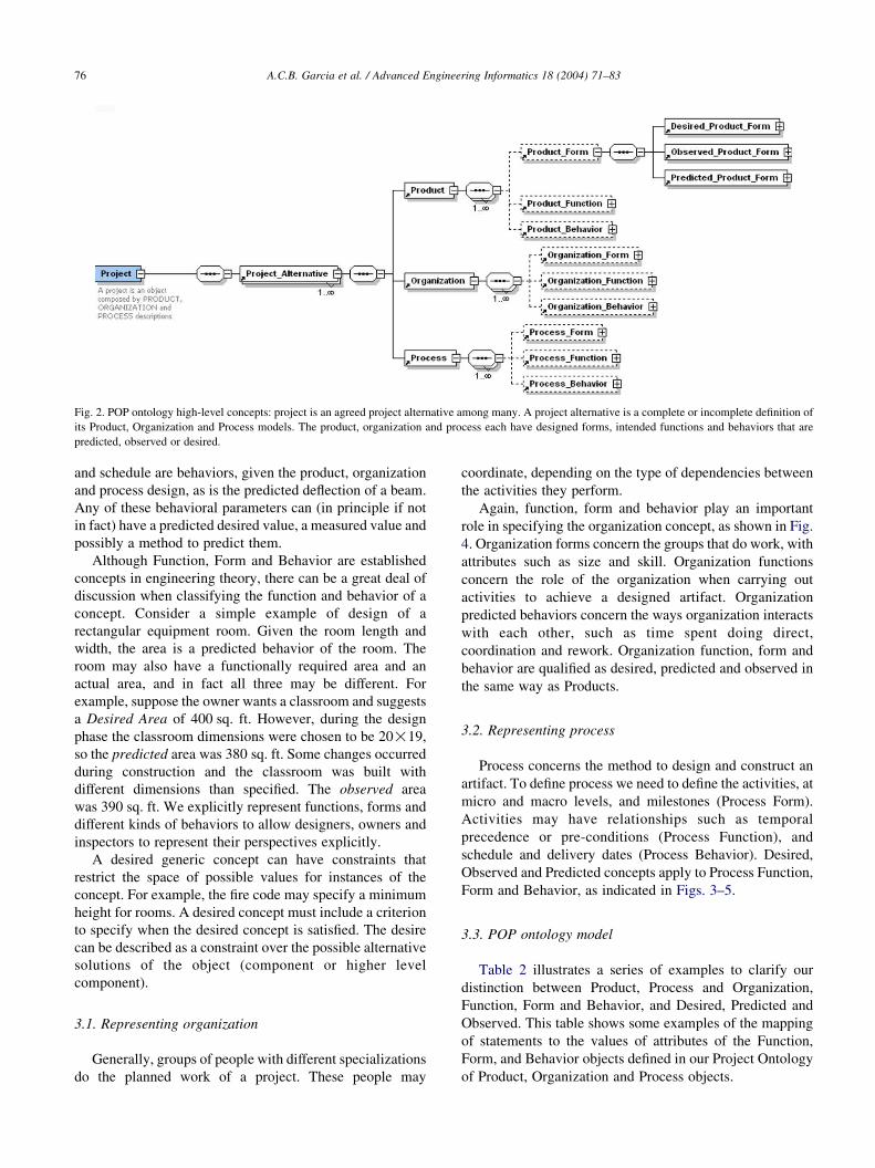
Fig. 2. POP ontology high-level concepts: project is an agreed project alternative among many. A project alternative is a complete or incomplete definition of
its Product, Organization and Process models. The product, organization and process each have designed forms, intended functions and behaviors that are
predicted, observed or desired.
A.C.B. Garcia et al. / Advanced Engineering Informatics 18 (2004) 71–8376
and schedule are behaviors, given the product, organization
and process design, as is the predicted deflection of a beam.
Any of these behavioral parameters can (in principle if not
in fact) have a predicted desired value, a measured value and
possibly a method to predict them.
Although Function, Form and Behavior are established
concepts in engineering theory, there can be a great deal of
discussion when classifying the function and behavior of a
concept. Consider a simple example of design of a
rectangular equipment room. Given the room length and
width, the area is a predicted behavior of the room. The
room may also have a functionally required area and an
actual area, and in fact all three may be different. For
example, suppose the owner wants a classroom and suggests
a Desired Area of 400 sq. ft. However, during the design
phase the classroom dimensions were chosen to be 20!19,
so the predicted area was 380 sq. ft. Some changes occurred
during construction and the classroom was built with
different dimensions than specified. The observed area
was 390 sq. ft. We explicitly represent functions, forms and
different kinds of behaviors to allow designers, owners and
inspectors to represent their perspectives explicitly.
A desired generic concept can have constraints that
restrict the space of possible values for instances of the
concept. For example, the fire code may specify a minimum
height for rooms. A desired concept must include a criterion
to specify when the desired concept is satisfied. The desire
can be described as a constraint over the possible alternative
solutions of the object (component or higher level
component).
3.1. Representing organization
Generally, groups of people with different specializations
do the planned work of a project. These people may
coordinate, depending on the type of dependencies between
the activities they perform.
Again, function, form and behavior play an important
role in specifying the organization concept, as shown in Fig.
4. Organization forms concern the groups that do work, with
attributes such as size and skill. Organization functions
concern the role of the organization when carrying out
activities to achieve a designed artifact. Organization
predicted behaviors concern the ways organization interacts
with each other, such as time spent doing direct,
coordination and rework. Organization function, form and
behavior are qualified as desired, predicted and observed in
the same way as Products.
3.2. Representing process
Process concerns the method to design and construct an
artifact. To define process we need to define the activities, at
micro and macro levels, and milestones (Process Form).
Activities may have relationships such as temporal
precedence or pre-conditions (Process Function), and
schedule and delivery dates (Process Behavior). Desired,
Observed and Predicted concepts apply to Process Function,
Form and Behavior, as indicated in Figs. 3–5.
3.3. POP ontology model
Table 2 illustrates a series of examples to clarify our
distinction between Product, Process and Organization,
Function, Form and Behavior, and Desired, Predicted and
Observed. This table shows some examples of the mapping
of statements to the values of attributes of the Function,
Form, and Behavior objects defined in our Project Ontology
of Product, Organization and Process objects.

Fig. 3. Product Form generic specification. Product forms, which are designed, include examples such as spaces and walls, can have desired, observed and
predicted attribute values. Higher_level_components components inferred though a transformation function, such as abstraction or composition, applied to a
set of primitive or other higher-level components. For example, an electrical system would be classified a higher-level component.
A.C.B. Garcia et al. / Advanced Engineering Informatics 18 (2004) 71–83 77
4. The Template-Hospital Charrette project
The Template-Hospital Charrette project was a group
exercise presented at the end of the one-week 2003 CIFE
summer workshop. Our client is a large Health Maintenance
Organization that is constructing a series of around 20
hospitals in a 13-year period. It plans to develop and reuse
share the same core design, with nuances to comply with
topographic and other site differences. The high-level
architectural program for the template hospital served as
the initial project specification. The objective of the
charrette experiment was to show to an audience of about
20 project managers from different companies around the
world the nature, feasibility and potential benefits and costs
of using the Tripod engineering process.
4.1. Participants: the project team
Table 3 shows the CIFE design team for this experiment.
Fig. 4. Project organization generic specification. Designed organizational elemen
predicted attribute values. ‘Higher_Level_Human_Resources’ are groups, such a
4.2. Method: the tripod experiment
The experiment was built in an XC environment since the
team would remain collocated during the entire exercise. In
that sense, the audience could estimate the degree of help (or
harm) from XC.
The exercise facilitator introduced the participants and
the project problem to the audience. In addition to
presenting the problem and the team to the audience, he
presented the objectives of the exercise, i.e. it was a live
demonstration to show the feasibility of the engineering
tripod approach as well as to stimulate people to consider
potential benefits of using VDC, XC and a shared project
ontology.
From the beginning the facilitator emphasized the VDC
approach; i.e. to build the POP project model incrementally
and to consider the product, organization and process
concurrently. Team members contributed to the discussion
either voluntarily, triggered by some displayed information,
or as a response to an explicit request from the facilitator or
ts, such as design and construction teams, can have desired, observed and
s a design team, and ‘Human_Resources’ are individuals.

Fig. 5. Project process generic specification. Designed process elements, such as design and construction tasks, can have desired, observed and
predicted attribute values. ‘Higher_Level_Activities’ are networks of activities, i.e. detailed work methods, while ‘Activity’ is an individual activity
or task.
A.C.B. Garcia et al. / Advanced Engineering Informatics 18 (2004) 71–8378
another team member. As illustrated in Fig. 2 and Table 2,
the VDC ontology has a very simple representation. We
showed it on an iRoom display and manually created and
integrated it.
The discussions generated in the XC charrette reflected
two rounds of the design activity: an initial conceptual design
(VDC modeling Level 1), in which the team was concerned
to find a sound solution, and some preliminary detailed

Table 2
The VDC POP ontology represents statements about architectural and
engineering in an object-oriented way as the values of parameters of defined
conceptual objects
World Representation
Beam length must beZ100 ft
(functional requirement for an
attribute of a product com-
ponent)
Beam1.desired_lengthZ100 ft
Calculated room areaZ100 sq
ft (Calculated behavior of a an
attribute of a product com-
ponent)
Beam1.predicted_lengthZ100 ft
Construction must finish by
October, 1, 2004 (Functional
requirement for an attribute of
a process concept)
Activity271.desired_deadlineZ10/01/
2004
DPR was hired to build the
electrical systems (Observed
value of an attribute of an
organizational concept)
Organization1.observed_responsibleZDPR
In the first example, the statement is mapped to the specific object Beam1,
which is a subclass of the general object ‘Product’. The statement refers to
the object attribute Desired_Form_Parameter_Length. The attribute value
is 100 ft.
Table 4
Specific project POP ontology after the first discussions
Product Organization Process
Functional
require-
ments
Generic physical
components
Organization
Budget Completion
date
Completion date
Number of beds Budget Safety
Designed
forms,
Level 1
Generic physical
components
Organization
actors
Process activities
1 Site preparations Owner Start the construc-
tion
2 Ambulatory sur-
gical center
Community Construct Site
preparations
3 Nursing unit
floor
GC/CM Construct ambulat-
ory surgical center
4 Parking structure Architect Construct nursing
unit floor
5 Utility room Sub contractors Construct parking
structure
6 Ancillary block Sub consultants Construct utility
room
7 Medical office
building
Construct ancillary
block
8 Central utility
plant
Construct medical
office building
9 Loading Dock Construct central
utility plant
10 Landscaping and
paving
Construct loading
dock
Construct Land-
scaping and paving
Turnover
Predicted behaviors
Greatest predicted actor backlog
Each POP object explicitly represents the relationships with other POP
objects, e.g. process activities have a responsible organizational actor and
act on one or more physical product objects. The POP model contains some
details about each object. The application-specific P, O and P models
A.C.B. Garcia et al. / Advanced Engineering Informatics 18 (2004) 71–83 79
design, in which the team discussed problems in specific
components and activities (Level 2). These two discussions
were documented, as illustrated in Table 4, and represent the
objects in the evolving specific project ontology.
Each of the participants described POP data, proposed
POP design changes, evaluated suggestions, explained
decisions and propositions, predicted impacts on individual
tasks due to other’s design changes, negotiated changes and
finally committed to an integrated solution.
Although the exercise accomplished the expected goals,
product, organization and process models stayed on a high
level of abstraction. We ended up with 10-15 highlevel objects
that represented the Product, Organization and Process.
contain a great deal more information4.3. Experiment results
4.3.1. Models
In a six-hour period, a group of six graduate students
generated a conceptual design for an actual engineering
Table 3
CIFE extreme collaboration design team member task assignments
Task Tool Role
Create POP ontol-
ogy for the specific
project
MS excel VDC project coordinator
(coordinator)
Make explicit
business objectives
MSWord Owner’s representative
(representative)
Product model (3D) ADT (autodesk) Architect
Product model 4D CAD (common
point technologies)
Architect
Organization model SimVision (ePM) Project manager (PM)
Process model MSProject Project manager (PM)
project. They developed a product (3D drawings), an
organization and process models, as illustrated in Figs. 6–
8 respectively, an integrated project ontology, and a set of
PowerPoint slides that documented the architectural pro-
gram, the POP design response, and some of the important
predictions.
4.3.2. Process results
During the experiment, participants proposed incremen-
tal additions to the POP ontology, allowing design team
members to discuss and agree to proposed changes. Since
the initial representation was not completely instantiated,
the group had the chance to negotiate and adopt not only
project engineering terminology, but also the representation
technology.
The XC drastically changed the task event allocation
from a usual project review meeting. Normally, the decision

Fig. 6. Template hospital product model (left) as it existed at the initial (Level-1 VDC model) abstract level of detail, and (right) in a more detailed version
(Level-2). The left image is a snapshot from a 4D animation, which shows the construction of building components over time. The 4D snapshot shows major
building components at a moment during the construction, and the animation shows the constructed sequence occurring over time.
A.C.B. Garcia et al. / Advanced Engineering Informatics 18 (2004) 71–8380
events (Decide-type) are rare (less than 5%) either because
people spend most of meeting-time understanding the
context, and/or because participants delegate decision-
making to others. As illustrated in Fig. 9, decisionmaking
events were about 21% in the XC session, probably because
Fig. 7. Template hospital solution: organization model. The process activities (rect
product model.
the group’s goal was to come up with solution during the
meeting, the XC environment facilitated rapid decision-
making; the ontology allowed everyone to view proposed
decisions; and the iRoom made the designs public for all
to see.
angles) describe the design and construction of the component objects of the

Fig. 8. Hospital template project process schedule, predicted by simulation of the organization and process model shown in Fig. 7.
A.C.B. Garcia et al. / Advanced Engineering Informatics 18 (2004) 71–83 81
The design meetings were fully annotated and each
participant utterance during the meeting was codified
according to the DEEPAND (Describe, Explain, Evaluate,
Predict, Analyze, Negotiate and Decide events) coding
method.
Another expected result was the decrease on the amount
of Negotiate-type of events, from the usual 15% to less than
5%. As expected, the XC environment let people perceive
needs and volunteer information and predictions before
being requested, almost if everybody knew what to do
without need for explicit task division.
Another interesting finding, although unexpected, was
that the Predict-type events were the same 2–3% in normal
practice and in the XC experiment. We expected an increase
of Predict-events since they occurred during the XC
meeting. As we analyzed the transcripts, we noticed that
although working as a group during the meeting, partici-
pants foresaw information needs before being requested, ran
their analysis/modeling tools and brought results either as a
Describe-event or as a formulate Alternative-event. They
did prediction on their own initiative, without an initiating
social event to request it.
In our experiment, there was only minor rework due to
misunderstandings. The misunderstandings occurred just
before lunchtime.
More explanation and evaluation events occurred (about
40%) during the design exercise than the usual 20%. When
Fig. 9. A usual project design meeting (Left, from [4]) compared to the Hospital ch
inquires during the design session that were of each DEEPAND type. The lighter co
was both timely and of satisfactory quality to serve the intent of the questioner.
further analyzed, we judged that a great deal of the
explanative events were an expected side effect of the
VDC approach, i.e. each participant sought at least a
minimum understanding of the others’ design issues and
choices.
The presence of the audience strongly influenced the
process. One significant impact was the constant need to
show information to the audience. Despite this extra need,
Describetype events were drastically diminished from the
usual 40-50% to a modest value of 22%.
After the experiment we asked both the audience and the
design team to answer a survey. Our goal was to measure:
Usefulness of the experiment; i.e. in what degree the
experiment was useful to understand the Tripod approach
from both perspectives: designers and audience;
Soundness of the experiment; i.e. in what degree both
participants and audience believe the experiment was valid
to show the feasibility of POP ontology, VDC approach and
XC work environment
Maturity of the Tripod approach; i.e. in what degree they
believe they can input this new engineering process and
technology into their companies
The feedback of the audience was highly polarized,
either very positive or very negative.
We infer that this bimodal response reflects the
individual interests to modeling tools and methods. People
uninterested in details, get bored looking at people using
arrette design meeting exercise (right). The dark areas show the fraction of
lored area shows the fraction of those inquiries that received a response that

A.C.B. Garcia et al. / Advanced Engineering Informatics 18 (2004) 71–8382
tools. On the other hand, many observers found the process
interesting, suggestive of important potential for their own
work.
5. Discussion
This paper shows how a POP ontology complements
VDC modeling and extreme collaboration to produce very
fast schematic level design. We claim, based on the results
of this experiment and our related experiences, that using
VDC, XC and a POP ontology together facilitate vastly
faster and more effective early design, which in turn
potentially may lead to faster, better and potentially safer
and less expensive project development.
This paper presents the Tripod model and its three
components: the generic POP ontology, VDC engineering
process and XC working style respectively. In the case study
section, a team of six graduate students developed a set of
product, organization and process models and an instan-
tiated POP ontology at the schematic level plus some detail
for a specific project in a six-hour project design session.
Professional observers reported that this session was far
more productive than what they see in the same period of
time in their own practices.
VDC is a paradigm for engineering design. In the VDC
method, designers concurrently design the major control-
lable factors of a project, i.e. the Product, Organization and
Process. XC involves collaborative group working. The
objective is to speed up a negotiated understanding of the
problem and the solution. It emphasizes the gains of having
the design team addressing the design problem at the same
time at the same place.
While most in the observing audience reported that the
tripod approach did not yet seem mature enough to justify a
drastic change in their company’s way of doing business
today, some reported that they would try parts of it, as
indeed several now have. Some of the parts of the tripod
approach are in use in some segments of industry today, i.e.
cross-functional co-located teams, multi-display working
environments like the iRoom, extreme collaboration and
modeling tools. We focused this paper on the ontology
because we found that it s formal definition facilitated rapid
work, but that its small size and simple (Excel) implemen-
tation are usable and useful today.
The use of an ontology, natural for an engineering team
and audience, helped fast understanding by design session
participants and observers. We believe that the iRoom
technology speeded up understanding by allowing infor-
mation to be presented and discussed in an integrated view.
For example, when discussing a set of activities (process
model) presented in a screen, the related components
(product model) could be presented in a second screen, and
the responsible players (organization model) in a third
screen. This holistic view of the project suggested by the
VDC approach supported by the POP ontology allows
information always to be presented in its proper context,
speeding up understanding. The holistic perspective also
appeared to diminish rework below that seen in normal
design processes.
As shown in Figs. 2–5, the original generic ontology is
very simple, especially in contrast with industry standard
ontologies such as the IFC or STEP. During our extreme
collaboration sessions, the only extension to the generic
ontology we routinely make is to add clarifying or
explanatory assumptions. Since the format and meaning of
these assumptions tends to be project specific, we have not
yet chosen to add assumptions to the generic ontology.
During the experiment discussed in this paper, we did not
extend the original generic ontology. It is important to note
that, unlike the IFC, STEP or the JPL ontologies, our
generic ontology does not commit to names of function or
objects, e.g. ‘support’, ‘beams’ or ‘girders.’ The project
team makes those commitments for the project, although
companies or communities could make such ontological
commitments as part of a defined generic ontology. Thus,
during the extreme collaboration design session, we create,
add and may modify each instance functional and form
object in the POP model and the names of each behavioral
attribute. In our observation of the JPL extreme collabor-
ation process, the team starts with a generic ontology that
commits to somewhat more than 2000 attributes of a large
set of defined function and form objects. The JPL team
reports that it routinely chooses to instantiate 80–90% of
those predefined attributes during a (three day) design
session, and it may add a few instance attributes for a
particular project. Thus, although our starting ontology is
dramatically less committed than that of JPL, IFC or STEP,
each of which evolved over many years, our practice of
instantiating a very simple generic ontology works effec-
tively for projects that lack years of focused ontological
development history. This bottom up approach for building
the project ontology builds acceptance by participants
because the team builds it up through small group
negotiation, which the process and technology of extreme
collaboration encourage.
We speculate that the power of the Tripod method comes
from the synergy of its three parts: the VDC modeling, POP
model and extreme collaboration. Our experience in AEC
with newly formed teams is consistent with the decade-long
JPL experience in designing space exploration missions.
Other practitioners and researchers emphasize each of the
tripod elements individually. For example, different kinds of
virtual modeling are common in engineering practice; some
practitioners, particularly in Mechanical Engineering, sub-
stantively use generic ontologies such as STEP; and some
engineers routinely use collocated cross-disciplinary design
teams. We find that, even for newly constituted teams, the
use of the Tripod ensemble provides good schematic-level
designs surprisingly quickly (a few hours in class exercises
to a day in the experiment we discuss in this paper). Using
the tripod method, the team creates, understands and

A.C.B. Garcia et al. / Advanced Engineering Informatics 18 (2004) 71–83 83
analyzes product, organization and process models that are
clear to all the participants and have a high level of mutual
consistency. The tripod foundation on the theoretically
founded ontology appears to allow practitioners to come
together and start effective work within minutes rather than
days or weeks, and it allows participants to discuss their
respective perspectives with precision and clarity almost
from the first few minutes of the start of the design process.
In our individual and collective experiences, this rapid
convergence on a usable shared vocabulary is dramatically
shorter and more effective using the tripod method than
standard methods.
References
[1] Clayton MJ, Kunz JC, Fischer MA. Rapid conceptual design
evaluation using a virtual product model. Engineering Applications
of Artificial Intelligence 1996;9(4):439–51.
[2] Kunz J. Smoothing out the construction process: team coordination
starts with ‘virtual design and construction’; 2003 http://www.djc.
com/news/co/11143361.html.
[3] Kunz J, Fischer M, Liston K, Singhal V, Stone M. Virtual design and
construction in the CIFE iRoom, in the Proceedings of the Third
International Conference on Decision-Making in Urban and Civil
Engineering, London, England; 2002
[4] Garcia ACB, Kunz J, Fischer M. Meeting details: methods to
instrument meetings and use agenda voting to make them more
effective CIFE technical report #147; 2003 http://cife.stanford.edu/
online.publications/TR147.pdf.
[5] Johanson B, Fox A, Winograd T. The interactive workspaces project:
experiences with ubiquitous computing rooms. IEEE Pervasive
Computing Magazine 2002;1(2).
[6] Levitt R, Kunz J. Design your project organization as engineers design
bridges, CIFE Technical Report (CIFE WP 73); 2002
[7] Costello R, Jacobs D. The Mitre Corporation; 2003 http://www.
xfront.com/owl/.
[8] Gruber T. A translation approach to portable ontologies. Knowledge
Acquisition 1993;5(2):199–220.
[9] Kunz J, Levitt R, Fischer M. Management and leadership education
for civil engineers: teaching virtual design and construction for
sustainability (CIFE WP079);2003 http://cife.stanford.edu/online.
publications/WP079.pdf.
[10] Lenat DB, Guha RV, Ideas for applying Cyc, Tech Report. ACT-
CYC-407-91, MCC: Austin TX; 1991
[11] International alliance of interoperability (IAI). IFC 2x extension
modeling guide; 2001 http://www.iai.org.uk Available from.
[12] Gero JS. Design prototypes: a knowledge representation schema for
design. AI Mag 1990;11(4):26–36.
[13] Sasajima M, Kitamura Y, Ikeda M, Mizoguchi R. FBRL: a function
and behavior representation language, In proceedings of IJCAI-95;
1995
[14] Mark G. Extreme collaboration. Commun ACM 2000;45(6):89–93.
[15] Thompson JD. Organizations in action, McGraw-Hill, New York,
1967.


