
LB 1371
17.06.2004
Multicalor 45Multicalor 70Multicalor 100Multicalor 120Multicalor 140PR/MD Gas / AB GasolioPR/MD Gas / AB Light oil
A BRUCIATORI MISTI GAS + GASOLIOB GAS/LIGHT-OIL DUAL BURNERS

pag.2
A LB 1371 Multicalor 45 ÷ 140
Multicalor 45 70 100 120 140Potenza termica max. kW 500 700 1000 1200 1300
kcal/h 430.000 602.000 860.000 1.032.000 1.118.00Potenza termica min. kW 120 190 200 180 250
kcal/h 103.200 163.400 172.000 154.800 215.000Tensione di alim.trifase + neutro 50 HzV 230 / 400 230 / 400 230 / 400 230 / 400 230 / 400Motore kW 0,55 0,74 1,1 2,2 2,2Giri/minuto del motore N° 2800 2800 2800 2800 2800
CARATTERISTICHE OPERATIVE Modello : Multicalor 45-70-100-120-140 Categoria gas - II 2H 3+
G20 G25 G31 G30Pressione massima mbar 25 - 45 -Pressione minima mbar 17 - 25 -Combustibile gas P.C.I. kcal/Nm3 8.570 - 22.260 -Combustibile gasolio P.C.I. = 10.200 kcal/kg max 1,5° E a 20° C
CARATTERISTICHE TECNICHE
CAMPO DI LAVORO DEI BRUCIATORI
Con
trop
ress
ione
in c
amer
a di
com
bust
ione
Potenza
DIMENSIONI DI INGOMBRO
MODELLI A B C D D1 E F G H I L M N OMulticalor 45 780 330 450 170 330 555 160 385 225• 190 190 M10 115 165Multicalor 70 780 330 450 170 390 555 190 385 225• 190 190 M10 115 165Multicalor 100 780 330 450 175 395 555 190 385 225• 190 190 M10 115 165Multicalor 120 800 350 450 310 470 555 215 385 225• 190 190 M10 115 165Multicalor 140 800 350 450 310 470 555 215 385 225• 190 190 M10 115 165
G
M
L
I
F
D - D1ECB
A
H
N
O
D = testa corta D1 = testa lunga • = (OPZIONE) Dimensioni (mm)
150100 200
200100 300 400 500 600 700 800 900 1000 1100
250 300 350 400 450 500 550 600 650 700 750 800 850 900 950 1000 1050 1100 1150 1200 1250 13000
1
2
3
4
5
6
7
8
9mbar
kW
kcal/h x 1000
Multicalor 70 PR Multicalor 100 PR Multicalor 120 PR
Multicalor 140 PR
Multicalor 45 PR
NB. : Campi di lavoro riferiti al funzionamento a gas PR/MD.
pag.3
A LB 1371 Multicalor 45 ÷ 140
FUNZIONAMENTO DEL BRUCIATORE A GASPrima di accendere il bruciatore, assicurarsi che sia montato correttamente. Controllare i collegamenti elettrici secondo idiagrammi e le tubazioni dell’impianto. Prima del collegamento elettrico assicurarsi che il voltaggio corrisponda ai datiindicati nella targhetta caratteristiche.Il diagramma del collegamento elettrico e il ciclo di avviamento sono illustratiseparatamente. Per collegare l’apparecchiatura al bruciatore, vedere lo schema. Prestare particolarmente attenzione alcollegamento del neutro e della fase: non scambiarli mai. Controllare il collegamento terra dell’impianto. Nei motoritrifase controllare il senso di rotazione del motore (vedere freccia). Sfiatare l’aria e le impurità della tubazione del gas.Controllare che la pressione del gas sia nei limiti indicati nella targhetta. Questo controllo deveessere effettuato con un manometro gas nell’apposita presa di pressione prevista sul bruciatore.Si avvia il motore ed inizia la preventilazione. Il motoriduttore porta la serranda dell’aria allamassima apertura in circa 30 secondi. Quando il motoriduttore é completamente aperto, unsegnale all’apparecchiatura elettronica di controllo avvia un ciclo di preventilazione di circa 66secondi. Alla fine di questa preventilazione, il motoriduttore porta la serranda in bassa fiammapermettendo l’accensione del bruciatore alla minima portata. Contemporaneamente il trasformatore di accensione vienealimentato e dopo tre secondi (pre-accensione) vengono alimentate le valvole del gas. A questo punto la valvola a farfallaregola la portata del gas nella testa di combustione. Due secondi dopo l’apertura delle valvole, il trasformatore é esclusodal circuito. In caso di mancanza di accensione il bruciatore va in blocco entro due secondi. Il bruciatore si trova accesoalla minima potenza (circa 30% della massima potenza). Lo strumento modulatore farà aprire il servomotore alla massi-ma potenza o lo fermerà alla potenza intermedia richiesta dall’impianto. L’apertura del servomotore farà aprire gas edaria in modo proporzionale per avere sempre a tutte le portate (30%-100%) una combustione ottimale. Al termine delfunzionamento il servomotore si porta in posizione di chiusura.
CONSIGLI IMPORTANTITutti gli organi regolabili devono essere fissati dall’installatore dopo le regolazioni. Ad ogni regolazione controllate lacombustione al camino. I valori di CO2 devono essere circa 9,7 (G20) 9,6 (G25) 11,7 (I3B) 11,7 (I3P) ed il CO infe-riore a 75 ppm.
0
12
0 - STOP1 - GASOLIO2 - GAS
ALLACCIAMENTO ELETTRICOTutti i bruciatori sono collaudati a 400 V 50 Hz trifase per i motori e 230V 50 Hz monofase con neutro per gli ausilia-ri. Se fosse necessario alimentare il bruciatore a 230 V 50 Hz trifase senza neutro, eseguire le modifiche necessarie rife-rendosi allo specifico schema elettrico del bruciatore e controllare che il relé termico sia entro il campo di assorbimentodel motore. Accertare inoltre il corretto senso di rotazione del motore del ventilatore.
ALLACCIAMENTO ALLA LINEA GASAllacciato il bruciatore alla tubazione del gas è necessario assicurarsi che quest’ultima sia a tenuta perfetta. Assicurarsipure che il camino non sia ostruito. Aperto il rubinetto del gas sfiatare con prudenza la tubazione attraverso l’appositapresa di pressione e quindi controllare il valore della pressione con un manometro idoneo. Dare tensione all’impianto eregolare i termostati alla temperatura desiderata. Alla chiusura dei termostati, il dispositivo di controllo fughe gas effet-tua una prova di tenuta delle valvole; Al termine della prova il bruciatore riceve il consenso per effettuare il ciclo diavviamento.
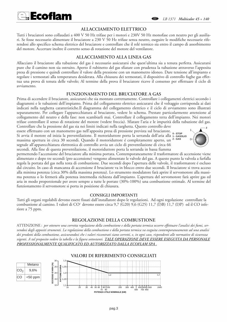
REGOLAZIONE DELLA COMBUSTIONE ATTENZIONE : per ottenere una corretta regolazione della combustione e della portata termica occorre effettuare l'analisi dei fumi, ser-vendosi degli appositi strumenti. La regolazione della combustione e della portata termica va eseguita contemporaneamente ad una analisidei prodotti della combustione, assicurandosi che i valori riscontrati siano corretti, e, in ogni caso, rispondenti alle normative di sicurezzavigenti. A tal proposito vedere la tabella e la figura sottostanti. TALE OPERAZIONE DEVE ESSERE ESEGUITA DA PERSONALEPROFESSIONALMENTE QUALIFICATO ED AUTORIZZATO DALLA ECOFLAM SPA .
EC
CE
SS
O D
'AR
IA (
%)
FA
TT
OR
E D
'AR
IA
1010 20 30 40 50 60
7080
90100 200 300 400
500600
700800
9001000 2000
1,1
1,15
1,21,2 1,2
1,25
1,3
15
20
25
30
POTENZA UTILE NOMINALE (kW)
Metano
CO2 9,6%
CO <50 ppm
VALORI DI RIFERIMENTO CONSIGLIATI

pag.4
A LB 1371 Multicalor 45 ÷ 140
APPARECCHIATURA LANDIS & STAEFA LGB 21/LGB 22 - LMG 21/LMG 22L’apparecchiatura Landis avvia il ventilatore e inizia la fase di prelavaggio della camera di combustione. Il corretto funzionamento écontrollato tramite il pressostato aria. Al termine della preventilazione, viene inserito il trasformatore di accensione e successivamen-te le valvole gas. In caso di mancata accensione o spegnimento accidentale la sonda di ionizzazione interviene mandando in bloccol’apparecchiatura entro il tempo di sicurezza.
SOLO PER APPARECCHIATURE LMG 21/LMG 22: In caso di blocco é disponibile l’indicazione della causa che ha provocatoil blocco. Operare come segue: con l’apparecchiatura in blocco (led rosso acceso) tenere premuto il pulsante di sblocco per più 3secondi, quindi rilasciarlo. Il led rosso inizierà a lampeggiare indicando la causa secondo la seguente tabella:
Codice errore Possibile causa2 lampeggi Mancanza di innesco di fiamma alla fine del tempo di sicurezza apparecchiatura3 lampeggi Il controllo della pressione aria non chiude4 lampeggi Il controllo della pressione aria non apre o presenza di luci estranee all'avviamento del bruciatore7 lampeggi Mancanza di fiamma duraante il funzionamento8÷17 lamp. Non utilizzati18 lampeggi Il controllo pressione aria apre durante la pre-ventilazione od il funzionamento19 lampeggi Contatti in uscita difettosi20 lampeggi Guasto del dispositivo interno
Durante la fase di diagnostica del guasto, i controlli in uscita sono disattivati. - Il bruciatore rimane in blocco - Eccezione: il segnale di guasto "AL" sul terminale 10: Il bruciatore sarà alimentato solo dopo aver effettuato il Reset- Per sbloccare l’apparecchiatura: premere il pulsante di riarmo del blocco da 0.5 a 3 secondi
��
�� ��
��
��
��
�� � ����
� ���� �� � � ����
������� ���
������� ����� ���� �
������������ � ��� ��
���������� �� �
����� ��� �����
���������� ��� Descrizione�� ��!� � �������� �� !��������� �� � 45
�� ��!� � ����� ���� ������ ����
!��� �� ���6�� � �5
�� ��!� � !���� ��� �� �75
�� ��!� � � ����� �5
�� ��!� � !���� �� �5
�� ��!� !� � ������ ���� �����
������� �� ������ � � 85
Messaggio Codice Lampeggioper interr.contr. ❘ ❘.ariapreventilazione (tv1) ❘ ❘ ❘ .pre-accensione (tvz) ❘ ❘ ❘ ❘.tempo di sicurezza (ts) ❙ ❘.ritardo 2° stadio (tv2) ❙ ❘ ❘ .in funzione ❘ _bassa tensione di rete ❘ ❙ ❙ _fusibile interno guasto ❘ ❙ _unità guasta
Descrizioneimpulso breve ❘impulso lungo ❙pausa breve .pausa lunga _
SATRONIC DMG 972 L'apparecchiatura di controllo SATRONIC DMG 972 ha un microprocessore che fornisce informazioni costanti sullasequenza di programmazione del bruciatore e sulle cause di eventuali disfunzioni (difetti). L'informazione è disponibileleggendo il codicelampeggiante nel LED all’interno dell tasto di reset. Usando il terminale aggiuntivo (opzionale) èpossibile avere un piccolo storico registrato dei precedenti malfunzionamenti e vizualizzarli in qualunque forma leggibi-le. Ci sono 2 tipi di dispositivi di controllo supplementari disponibili dalla Satronic. La "satropen" (= cioè la pennaSatronic) che è un piccolo lettore tascabile disegnato per dare una lettura visuale dello status, della fiamma e del voltag-gio disponibile. Il software computer è disponibile per permettere l'accesso alle informazioni correnti e ai dati preceden-temente registrati.
DIAGNOSI DEI BLOCCHIIn caso di guasto, il LED si illumina stabilmente. Ogni 10 secondi l’illuminazione viene interrotta da un codice di lampeggio cheindica la causa dell’errore. Viene quindi osservata la sequenza sotto riportata, che viene ripetuta finchè l’unità non viene risettata.

pag.5
A LB 1371 Multicalor 45 ÷ 140
Diagnosi erroreMessaggio errore Codice lampeggio Possibile guastoblocco ❘ ❙ ❙ ❙ ❙ entro tempo di sicurezzatempo di sicurezza blocco fiamma non prodottainterruttore controllo ❘ ❙ ❘ ❘ ❘ interuttore controlloaria in posizione chiusa aria contatto saldatointerruttore controllo ❘ ❘ ❘ ❙ ❙ interuttore controllo aria nonaria time-out si chiude nel tempo specificatointerruttore controllo ❘ ❘ ❘ ❘ ❙ interuttore controllo aria siaperto apre all’avviamento o durante il
funzionamentoperdita di fiamma ❙ ❙ ❙ ❙ ❘ perdita di fiamma durante il
funzionamentoCodice lampeggio per blocco manualemanuale/esterno ❘ ❘ ❙ ❙ ❙ ❙ ❙ ❙ ❙ ❙blocco (vedere anche terzo blocco e risettaggio)
ASPIRAZIONE
RITORNO
VgS
Vg2
Vg1
VGVGS
1 2 3
4
5
6987
CIRCUITO IDRAULICO GAS
1 - POMPA2 - VALVOLA GASOLIO DI SICUREZZA3 - VALVOLA GASOLIO 1° STADIO4 - VALVOLA GASOLIO 2° STADIO5 - UGELLO 1° STADIO6 - UGELLO 2° STADIO7 - PRESSOSTATO GAS8 - VALVOLA GAS DI SICUREZZA9 - VALVOLA GAS
Per calcolare la portata di funzionamento, in kW, del bruciatore, procedere nel modo seguente:
Controllare al contatore la quantità di litri erogati e la durata, in secondi, della lettura, quindi procedereal calcolo della portata secondo la seguente formula:
CALCOLO DELLA PORTATA DI FUNZIONAMENTO DEL BRUCIATORE
e x f = kWs
e = Litri di gass = Tempo in secondi
G20 = 34,02G25 = 29,25G30 = 116G31 = 88
f

pag.6
A LB 1371 Multicalor 45 ÷ 140
TARATURA DEL PRESSOSTATO GAS DI MINIMA PRESSIONE- svitare le viti I e L e togliere il coperchio M- posizionare il regolatore N ad un valore pari al 60% della pressione nominale di ali-
mentazione gas (es.: per gas metano press. nominale =20 mbar; regolatore posiziona-to al valore 12 mbar.
- rimontare il coperchio M e riavvitare le viti I e L
TARATURA DEL PRESSOSTATO ARIA- svitare le viti A e B e togliere il coperchio C - tarare il pressostato aria al minimo,
ruotando il regolatore D in posizione 1. - avviare il bruciatore e impostare il funzio-namento in 1° stadio (1 fiamma). - verificare la corretta combustione. - con l’ausi-lio di un cartoncino ostruire progressivamente il condotto di aspirazione dell’aria finoad ottenere un aumento del valore di CO2 di circa 0,5÷0,8 %, oppure, se si disponedi un manometro collegato alla presa di pressione E, fino ad ottenere una diminuzio-ne di 0,1 mbar (~10 mm C.A.).
- aumentare lentamente il valore di taratura del pressostato, fino a causare lo spegni-mento in blocco del bruciatore. - togliere l’ostruzione al condotto di aspirazione ariae rimontare il coperchio C. - ripristinare il funzionamento del bruciatore agendo sulpulsante di sblocco dell’apparecchiatura.
N.B.) - La pressione misurata alla presa E deve rientrare nel campo di lavoro del pressostato. Se ciònon fosse. allen-tare il dado di bloccaggio alla base della vite F ed agire gradualmente sulla stessa; in senso orario per diminuire lapressione, antiorario per aumentarla. Al termine della regolazione, ribloccare il dado di bloccaggio.
2,55
10 15
50
25
35
30
4045
20
0,4
0,6 0,9
3,0
1,5
2,1
1,8
2,42,7
1,2
I
L
MN
A
B
CD
E
F
GH
Togliere il coperchio per accedere alle camme di regolazione. Lo spostamentodelle camme va effettuato con l’ausilio dell’apposita chiavetta in dotazione.Descrizione :
I - Camma di regolazione posizione di apertura in fiamma potenza max.II - Camma di regolazione della posizione serranda allo spegnimento
(chiusura)III - Camma di regolazione posizione di apertura in fiamma potenza min.V - Non utilizzata
SERVOCOMANDO ARIA LANDIS & STAEFA SQN 31 251A2700
LEVA DI SBLOCCO
2
COMMUTATORE
0
AUTO
0 = bloccaggio degli apparati per il funzionamento in una posizione intermadia = funzionamento alla massima potenza = funzionamento alla minima potenza
AUTO = funzionamento automatico
REGOLAZIONE DELLA PORTATA ARIA E GAS
13

pag.7
A LB 1371 Multicalor 45 ÷ 140
FUNZIONAMENTO DEL BRUCIATORE A GASOLIOI bruciatori misti gas gasolio devono essere regolati sempre come prima accensione a gasolio.Dopo aver eseguito l’installazione del bruciatore, verificare i seguenti punti: * Tensione d’alimentazione del bruciatore ed i fusibili di protezione di rete.* I collegamenti del motore.* La corretta lunghezza delle tubazioni e la loro tenuta.* Il tipo di combustibile, che deve essere adatto al bruciatore.* Il collegamento dei termostati caldaia e le varie sicurezze.* Il senso di rotazione del motore.* La corretta taratura della protezione del motore. Quando tutte queste condizioni sono verificate e soddisfatte, si può procedere con il collaudodel bruciatore.Girare l’interruttore sulla posizione "1" gasolio; dare tensione al bruciatore. L’apparecchiaturadi controllo alimenterà, allo stesso tempo, sia il trasformatore di accensione sia il motore delbruciatore, che provvederà ad effettuare un prelavaggio della camera di combustione alla massi-ma portata d’aria. Al termine del prelavaggio il servocomando si predispone nella posizione di1° stadio gasolio, l’apparecchiatura di controllo apre le elettrovalvole “valvola di sicurezza” e “valvola 1° stadio”. Essendo già presente la scarica prodotta dal trasformatore il bruciatore si accende. Dopo l’intervallo di sicurezza di 5secondi, ad accensione avvenuta, l’apparecchiatura di controllo disinserisce il trasformatore, dopo 10 secondi passa in2° stadio (ALTA).In caso di accensione difettosa, l’apparecchiatura di controllo causa il blocco del bruciatore entro 5secondi.In questo caso, il riar
0
12
0 - STOP1 - GASOLIO2 - GAS
REGOLAZIONE DELLA POTENZA MASSIMA DEL BRUCIATOREPosizionare il commutatore, situato nel quadro comandi, nella posizione massima potenza e agire come segue:Regolazione della portata massima del gas: agire come indicato nella regolazione elettrovalvole gas, sino al raggiungi-mento della portata corretta del gas determinata dall'analisi della combustione. Correggere eventualmente la portatamodificando la posizione della lamina di guida della camme(3) con una chiave a brugola adeguata; avvitando, la portataaumenta, svitando diminuisce.Regolazione della portata massima dell'aria : correggere eventualmente questa posizione agendo sulla vite “1” dopoaver allentato il dado “2”. Fissare nuovamente il dado “2”.
REGOLAZIONE DELLA POTENZA MINIMA DEL BRUCIATOREPosizionare il commutatore, situato nel quadro comandi, nella posizione minima potenza e agire come segue:Regolazione della portata minima del gas : Agendo con una chiave a brugola adeguata, modificare la posizione dellalamina di guida della camme(3); avvitando, la portata aumenta, svitando diminuisce.Regolazione della portata minima dell'aria : agire sulla camma di regolazione posizione di apertura in fiamma poten-za min.
REGOLAZIONE DELLE POTENZE INTERMEDIE DEL BRUCIATORECon il commutatore azionare il servomotore (chiusura o apertura) e posizionare nello 0 per fermare la corsa; per laregolazione agire come sottoindicato. Ripetere l’operazione per altri punti delle camme.Regolazione delle portate intermedie del gas : agendo con una chiave a brugola adeguata, modificare la posizione dellalamina di guida della camme(3); avvitando, la portata aumenta, svitando diminuisce.
pag.8
A LB 1371 Multicalor 45 ÷ 140
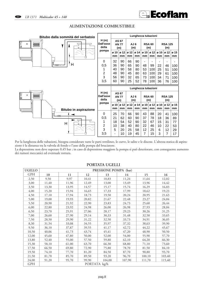
UGELLO PRESSIONE POMPA (bar)GPH 10 11 12 13 14 15 162,50 9,50 9,97 10,41 10,83 11,24 11,64 12,023,00 11,40 11,96 12,49 13,00 13,49 13,96 14,423,50 13,30 13,95 14,57 15,17 15,74 16,29 16,834,00 15,20 15,94 16,65 17,33 17,99 18,62 19,234,50 17,10 17,94 18,73 19,50 20,24 20,95 21,635,00 19,00 19,93 20,82 21,67 22,48 23,27 24,045,50 20,90 21,92 22,90 23,83 24,73 25,60 26,446,00 22,80 23,92 24,98 26,00 26,98 27,93 28,846,50 23,70 25,91 27,06 28,17 29,23 30,26 31,257,00 26,60 27,90 29,14 30,33 31,48 32,58 33,657,50 28,50 29,90 31,22 32,50 33,73 34,91 36,058,30 31,54 33,08 34,55 35,97 37,32 38,63 39,909,50 36,10 37,87 39,55 41,17 42,72 44,22 45,6710,50 40,06 41,73 43,74 45,41 47,20 48,90 50,5012,00 45,60 47,80 50,00 52,00 54,00 55,90 57,7013,80 52,40 55,00 57,50 59,80 62,10 64,20 66,3015,30 58,10 61,00 63,70 66,30 68,80 71,10 73,6017,50 66,50 69,80 72,90 75,80 78,70 81,50 84,1019,50 74,10 77,70 81,20 84,50 87,70 90,80 93,7021,50 81,70 85,70 89,50 93,20 96,70 100,10 103,4024,00 91,20 95,70 99,90 104,00 107,90 111,70 115,40GPH PORTATA kg/h
PORTATA UGELLI
H
H
Bitubo dalla sommità del serbatoio
Bitubo in aspirazione
H (m)Dall'asse
della pompa
Lunghezza tubazioni
ø 10mm
ø 12mm
00,5123
3,5
323640485660
909090909090
ø 12mm
ø 14mm
666558453225
909080806552
AS 67AN 77
(m)AJ 6(m)
252118105-
706254382010
666052402519
909090805845
RSA 60(m)
RSA 125(m)
ø 10mm
ø 12mm
ø 10mm
ø 12mm
ø 15mm
-4853637378
-99
100100100100
-2225293436
-4651617176
-100100100100100
H (m)Dall'asse
della pompa
Lunghezza tubazioni
ø 10mm
ø 12mm
00,5123
3,5
ø 12mm
ø 14mm
AS 67AN 77
(m)AJ 6(m)
RSA 60(m)
RSA 125(m)
ø 10mm
ø 12mm
ø 10mm
ø 12mm
ø 15mm
43373222127
887867462515
2018151063
41363122127
1008977532917
Per la lunghezza delle tubazioni, bisogna considerare tutte le parti rettilinee, le curve, le salite e le discese. L'altezza statica di aspira-zione è la distanza tra la valvola di fondo e l'asse della pompa del bruciatore.La depressione non deve superare 0,45 bar ; in caso di depressione maggiore la pompa si può deteriorare, con conseguente aumentodei rumori meccanici ed eventuale rottura.
ALIMENTAZIONE COMBUSTIBILE

La pompa é regolata al collaudo a 12 bar. - Controllare la perfetta tenuta delle tubazioni. - Usare tubo rigido dove èpossibile. - Dimensionare correttamente la valvola di fondo. - Non eccederenella depressione (max 0,45 bar). Spurgare l' aria contenuta nella pompaattraverso la presa di pressione e controllare la pressione. Riempire di gaso-lio le tubazioni per facilitare l' innesco. Non far funzionare la pompa senza
gasolio per più di tre minuti. Se l' innesco della pompa non avviene nel primo prelavaggio del bruciatore, riar-mare il blocco.NB.: Prima di mettere avviare il bruciatore, assicurarsi che il ritorno sia aperto. Una occlusione provocherebbela rottura dell' organo di tenuta della pompa.
pag.9
A LB 1371 Multicalor 45 ÷ 140
1° STADIO GASOLIO
ASPIRAZIONE
RITORNO
VgS
Vg2
Vg11 2 3
4
5
6VGVGS987
2° STADIO GASOLIO
ASPIRAZIONE
RITORNO
VgS
Vg2
Vg11 2 3
4
5
6VGVGS987
CIRCUITO IDRAULICO GASOLIO
A - FLESSIBILEB - FILTRO C - RUBINETTO 1 - POMPA2 - VALVOLA GASOLIO DI SICUREZZA3 - VALVOLA GASOLIO 1° STADIO4 - VALVOLA GASOLIO 2° STADIO5 - UGELLO 1° STADIO6 - UGELLO 2° STADIO7 - PRESSOSTATO GAS DI MINIMA8 - VALVOLA GAS DI SICUREZZA9 - VALVOLA GAS
Regolare la pressione del gasolio ed il flusso d’aria alprimo stadio. Il bruciatore resterà ora al primo stadiofino a quando l’interruttore non venga nuovamenteposizionato in secondo stadio. L’apparecchiatura iniziaallora il secondo stadio aprendo completamente la ser-randa aria e la pressione, al secondo stadio ed in condi-zioni normali di funzionamento,va selezionata a 12-15bar (controllare la lettura sul manometro al punto dipressione). Regolare l’aria di combustione mediante laleva di regolazione testa.
5
12
6
4
3
POMPA GASOLIO
6 5
4
3 3
3
SUNTECSUNTEC
P V
21
SUNTEC AN 67 C DANFOSS RSA 60-RSA 125
1 - ASPIRAZIONE2 - RITORNO3 - SFIATO E PRESA MANOMETRO4 - PRESA VUOTOMETRO5 - REGOLAZIONE PRESSIONE6 - ALL' UGELLO
1
1
2 3
SUNTEC AN 77
6 5
4
3 3
3
SUNTECSUNTEC
P V
21
pag.10
A LB 1371 Multicalor 45 ÷ 140
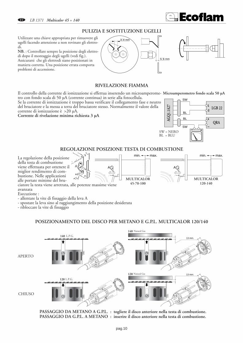
13 mm.120 Metano
13 mm.
140 Metano
120 G.P.L.
140 G.P.L.
APERTO
CHIUSO
POSIZIONAMENTO DEL DISCO PER METANO E G.P.L. MULTICALOR 120/140
L.P.G.
L.P.G.
Natural Gas
Natural Gas
PULIZIA E SOSTITUZIONE UGELLIUtilizzare una chiave appropriata per rimuovere gliugelli facendo attenzione a non rovinare gli elettro-di.NB. : Controllare sempre la posizione degli elettro-di dopo il montaggio degli ugelli (vedi fig.).Assicurarsi che gli elettrodi siano posizionati inmaniera corretta. Una posizione errata comportaproblemi di accensione.
5÷6 mm
3÷4 mm
2 fiamme
REGOLAZIONE POSIZIONE TESTA DI COMBUSTIONE
La regolazione della posizionedella testa di combustioneviene effettuata per ottenere ilmiglior rendimento di com-bustione. Nelle applicazionialle portate minime del bru-ciatore la testa viene arretrata, alle potenze massime vieneavanzataEsecuzione : - allentare la vite di fissaggio della leva A- spostare la leva sino al raggiungimento della posizione desiderata- ribloccare la vite di fissaggio
A
min. max.
A
min. max.
MULTICALOR45-70-100
MULTICALOR120-140
Il controllo della corrente di ionizzazione si effettua inserendo un microamperome-tro con fondo scala di 50 µA (corrente continua) in serie alla fotocellula.Se la corrente di ionizzazione è troppo bassa verificare il collegamento fase e neutrodel bruciatore e la messa a terra del bruciatore stesso. Normalmente il valore dellacorrente di ionizzazione è >20 µA.Corrente di rivelazione minima richiesta 3 µA
LGB 22
QRA
AGQ
1.1A
27 1
2
SW
SW
BL
BL
RIVELAZIONE FIAMMA
Microamperometro fondo scala 50 µA
SW = NEROBL = BLU
PASSAGGIO DA METANO A G.P.L. : togliere il disco anteriore nella testa di combustione.PASSAGGIO DA G.P.L. A METANO : inserire il disco anteriore nella testa di combustione.
pag.11
A LB 1371 Multicalor 45 ÷ 140
I
0
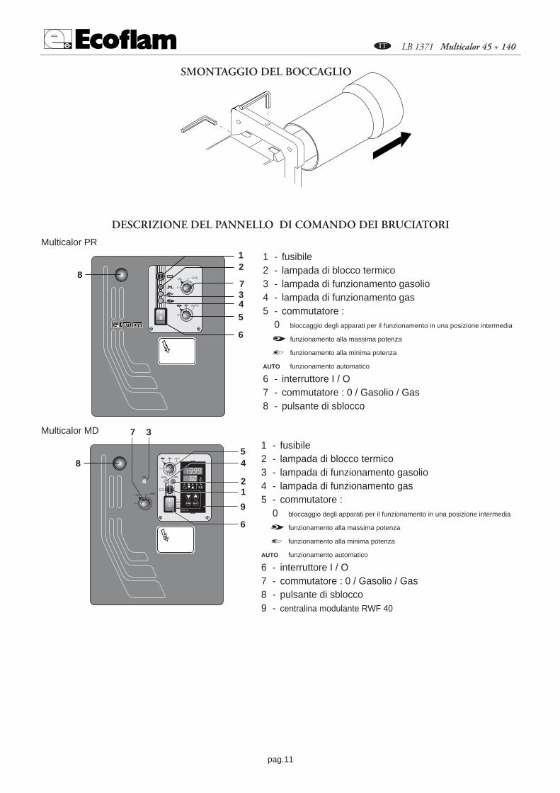
SMONTAGGIO DEL BOCCAGLIO
DESCRIZIONE DEL PANNELLO DI COMANDO DEI BRUCIATORI
1 - fusibile2 - lampada di blocco termico3 - lampada di funzionamento gasolio4 - lampada di funzionamento gas5 - commutatore : 0 bloccaggio degli apparati per il funzionamento in una posizione intermedia
funzionamento alla massima potenza
funzionamento alla minima potenza
AUTO funzionamento automatico
6 - interruttore I / O7 - commutatore : 0 / Gasolio / Gas8 - pulsante di sblocco
0I
12
6
3
54
87
0 12
0
OIL GAS
0
AUTO
PGM EXIT
PGM EXIT
PGM EXIT
0 12
1 - fusibile2 - lampada di blocco termico3 - lampada di funzionamento gasolio4 - lampada di funzionamento gas5 - commutatore : 0 bloccaggio degli apparati per il funzionamento in una posizione intermedia
funzionamento alla massima potenza
funzionamento alla minima potenza
AUTO funzionamento automatico
6 - interruttore I / O7 - commutatore : 0 / Gasolio / Gas8 - pulsante di sblocco9 - centralina modulante RWF 40
8
PGM EXIT
54
6
2
9
1
0
AUTO
0I
K6
RWF 40
PGMPGM EXITEXIT
7 3
0
OIL GAS
GASOIL
PGM EXIT
Multicalor PR
Multicalor MD

pag.12
A LB 1371 Multicalor 45 ÷ 140
REGOLATORE A MICROPROCESSORE RWF 40
Display:ingresso analogico
1 (valore reale)
Display: setpoint SP1
Diminuisce valore
Tasto programmazione
Funzionamento manuale
Contatto ausiliario
Aumenta valore
Tasto USCITA
FunzionamentoBruciatore
Diminuzione potenzaCHIUDI / 1 Stadio
Aumento potenzaAPRI / 2 Stadio
Funzionamento bistadio
Significato del display e dei tasti del regolatore a microprocessore RWF 40Nella figura viene visualizzato il display di base,
che indica il valore reale ed il setpointimpostato, é importante inoltre
il significato di ogni tasto e diogni led di segnalazione
Livello configurazione
Livello utente
Display normale
Livello parametri
PGM
PGM
PGM
PGM PGMPGM
PGM PGM
PGM PGM
min 2s
min 2s
min 2s
Exit
LIVELLI DI PROGRAMMAZIONE
pag.13
A LB 1371 Multicalor 45 ÷ 140
IMPOSTAZIONI PARAMETRIAll’accensione del bruciatore tutti i dislay del regolatore sono accesi, il display del setpoint lampeggerà per circa 10 sec. Il valorevisualizzato nel dislay superiore (rosso) indica il valore reale. Il valore visualizzato nel dislay inferiore (verde) indica il valore del set-point impostato.REGOLAZIONE DEL SETPOINT Per la regolazione del setpoint bisogna agire come segue.: ---- Con il pulsante PGMPGM si accede al livello utente, apparirà nel display dibase SP1*. - Modificare il valore del setpoint SP1 agendo sui tasti �e �. ---- Dopo 2 sec. il valore impostato viene automaticamentememorizzato. ---- Per ritornare nel display di base premere il pulsante EXITEXIT.** Il valore di SP1 dipende dal valore pre impostato nel livello di configurazione C111IMPOSTAZIONE PARAMETRI PIDI parametri PID sono già pre impostati in fabbrica su valori medi standard. E’ possibile adattare il funzionamento del regolatore infunzione dell’impianto, attivando la funzione Autoadattamento “tunE”. Il regolatore provvederà a impostare i parametri PID inautomatico. Per attivare la funzione “tunE” bisogna agire come segue: ---- Con il bruciatore in funzione avviare l’autoadattamentocon il pulsante PGM PGM + �. ---- Nel dislay apparirà la scritta “tunE*” lampeggiante. ---- Quando la scritta “tunE” termina il lampeggiol’autoadattamento è terminato. ---- Confermare i parametri calcolati tenendo premendo per 2 sec il tasto �. ** La funzione “tunE” non è attuabile in funzionamento manuale, o/a bruciatore spento.I parametri PID possono essere coretti manualmente dal livello parametri agendo sulla banda proporzionale Pb1, tempodell’azione derivata dt e il tempo dell’azione integrale rt. Per modificare i parametri Pb1, dt, rt, bisogna agire come segue: ---- Con il pulsante PGMPGM si accede al livello parametri. ---- Si passada un parametro al successivo premendo sempre PGMPGM. ---- Quando nel dislay apparirà la scritta Pb1. ---- Si aumenta o diminuisce ilvalore premendo i pulsanti �e �. ---- Confermare i parametri modificati premendo PGMPGM, se ciò non avviene il valore viene memo-rizzato automaticamente dopo 2 sec. ---- Con il pulsante PGMPGM si accede al successivo parametro. ---- Quando nel display apparirà lascritta dt si ripetono le istruzioni precedenti. ---- Con il pulsante PGMPGM si accede al successivo parametro. ---- Quando nel displayapparirà la scritta rt si ripetono le istruzioni precedenti. ---- Per ritornare nel display di base premere il pulsante EXITEXIT.REGOLAZIONE DIFFERENZIALE DI ACCENSIONE E SPEGNIMENTO.Il regolatore permette di impostare un differenziale di commutazione regolabile che stabilisce i valori di accensione e spegni-mento del bruciatore. Con HYS1 si intende il limite inferiore di accensione sotto tale soglia il regolatore commuta il bruciatorealla massima potenza, con HYS3 si intende il limite superiore di spegnimento superata tale soglia il regolatore spegne il brucia-tore. Per impostare HYS1 e HYS3 bisogna agire come segue: ---- Con il pulsante PGMPGM si accede al livello parametri. ---- Si passa daun parametro al successivo premendo sempre PGMPGM. ---- Quando nel dislay apparirà la scritta HYS1 (differenziale di accensione bru-ciatore II stadio). ---- Si aumenta o diminuisce il valore premendo i pulsanti �e �. ---- Confermare i parametri modificati premendoPGMPGM, se ciò non avviene il valore viene memorizzato automaticamente dopo 2 sec. ---- Con il pulsante PGMPGM si accede al successivoparametro. ---- Quando nel display apparirà la scritta HYS2 (differenziale di spegnimento bruciatore II stadio) si ripetono le istruzio-ni precedenti. ---- Con il pulsante PGMPGM si accede al successivo parametro. ---- Quando nel display apparirà la scritta HYS3 (differen-ziale superiore di spegnimento) si ripetono le istruzioni precedenti.---- Per ritornare nel display di base premere il pulsante EXITEXIT.FUNZIONAMENTO MANUALE / AUTOMATICOPer accedere alla funzionalità di funzionamento”MANUALE” premere il tasto EXIT EXIT per almeno 5 secondi.. Il funzionamentomanuale può essere inserito solamente quando il bruciatore è in funzione, si disattiva automaticamente quando il bruciatore si spe-gne. Quando è acceso il LED sopra il simbolo della mano il regolatore sta lavorando in manuale, si può cosi modificare la posizionedel servocomando con i tasti �e �. I LED accesi sul fronte del regolatore indicano se è attivo il comando APRI o CHIUDI delservocomando. Premendo il tasto � il servocomando si APRE. Premendo il tasto � il servocomando si CHIUDE. Per passare infunzionamento automatico bisogna premere il pulsante EXITEXIT per 5 sec. il LED sopra il simbolo della mano si spegne ed il regola-tore si trova ora in automatico.
COMPENSAZIONE CLIMATICA. Il regolatore RWF40 può essere configurato con il setpoint dipendente alla sonda esterna. Perché ciò avvenga bisogna impostare ilregolatore come segue: ---- Collegare la sonda desiderata come da schema elettrico. ---- Modificare impostazioni regolatore. Consonda esterna bisogna impostare il regolatore come segue: ---- Con il pulsante PGMPGM si accede al livello configurazione, quando neldislay apparirà la scritta C111 (XXXX), si utilizza il pulsante � finche si accede alla seconda cifra (XXXX), con il tasto � si impo-sta il tipo di sonda(XX3X). ---- Confermare i parametri modificati premendo PGMPGM , se ciò non avviene automaticamente dopo 2sec. il valore viene memorizzato. ---- Con il pulsante PGMPGM si accede al livello configurazione, quando nel dislay apparirà la scrittaC112 (XXXX), si utilizza il pulsante �finche si accede alla seconda cifra (XXXX),con il tasto � si imposta il tipo di sonda(XX1X). ---- Confermare i parametri modificati premendo PGMPGM, se ciò non avviene automaticamente dopo 2 sec. il valore viene memorizza-to. ---- Per ritornare nel display di base premere il pulsante EXITEXIT.Per l’impostazione della curva di riscaldamento il regolatore va impostato come segue:---- Con il pulsante PGMPGM si accede al livello parametri. ---- Si passa da un parametro al successivo premendo sempre PGMPGM.---- Quando nel dislay apparirà la scritta H (pendenza della curva di riscaldamento). ---- Si aumenta o diminuisce il valore premendo ipulsanti � e �. ---- Confermare i parametri modificati premendo PGMPGM, se ciò non avviene automaticamente dopo 2 sec. il valoreviene memorizzato. ---- Per ritornare nel display di base premere il pulsante EXITEXIT.

pag.14
A LB 1371 Multicalor 45 ÷ 140
SPH
60
80
100
0
20
40
SPL
120
140
160
20 15 10 5 0 -20-15-10-517.5 12.5 7.5 2.5 -2.5 -17.5-12.5-7.5
0.20.40.60.811.21.41.61.822.22.42.62.833.23.43.63.84
Temperatura esterna (¡C)
Set
po
int
tem
per
atu
ra c
ald
aia
(¡C
)
Pen
den
za c
urv
a ri
scal
dam
ento
( H
)
PARAMETRIZZAZIONE
Cod.S704
Cod. S721Cod.S731
S731/1S731/2S731/3S731/4
Cod.S720/1
Collegamento sondaQAE2..(sonda passiva)Sonda acquaCodice configurazioneC111 = 9XXX
Collegamento sondaFT-TP/..(sonda passiva)(sonda Degusa)Codice configurazioneC111 = 5XXX
Collegamento sonda QBE620-P..(sonde attive)Codice configurazione C111 = GXXXS731 - 0…4 bar / 0…400 kPa QBE620-P4 S731/1 - 0…10 bar / 0…1 MPa QBE620-P10 S731/2 - 0…16 bar / 0…1.6 Mpa QBE620-P16 S731/3 - 0…25 bar / 0…2.5 MPa QBE620-P25 S731/4 - 0…40 bar / 0…4 MPa QBE620-P40
Collegamento sondaQAC22 (sonda passiva)Codice configurazione C111 = XX3XC112 = XX1X
1 2 3 4
RWF 40
B M
G1+ M1
QAE22A
1 2 3 4
RWF 40
B M
B9 M9
QAC2..
1 2 3 4
RWF 40
GL M
G+ M1
OBE620-P..U1
G- U1
SCHEMI COLLEGAMENTO SONDE

pag.15
A LB 1371 Multicalor 45 ÷ 140
- Comportamento - Nel caso si abbia: nel dislay del valore reale il numero 1999 lampeggiante, e nel dislay del setpoint il valore del setpoint.
- Causa - Il valore reale non viene misurato. Significa che è stato superato verso l’alto o verso il basso il campo di misura dell’ingresso analogico1 (valore reale).
- Rimedio - Verificare i collegamenti elettrici e lo stato della sonda. Nel caso di guastodella sonda, il regolatore non rivela il valore reale della grandezza controllata, ne consegue uno spegnimento automatico di sicurezza, una disattivazione dell’autoadattamento e la disattivazione del funzionamento manuale.Il contatto ausiliario risponde a seconda della configurazione del parametro C113.
- Comportamento - Nel caso si abbia: nel dislay del valore reale il numero 1999 lampeggiante, e nel dislay del setpoint venga indicato tA.
- Causa - La temperatura esterna non viene misurata. Significa che è stato superatoverso l’alto o verso il basso il campo di misura dell’ingresso analogico3 (valore reale).
- Rimedio - Verificare i collegamenti elettrici e lo stato della sonda. Nel caso di guasto della sonda, il regolatore non rivela il valore reale.
- Comportamento - Nel caso si abbia: nel dislay del valore reale il numero1999 lampeggiante, e nel dislay del setpoint venga indicato SP .E
- Causa - Il valore del setpoint esterno non viene misurato. Significa che è stato superato verso l’alto o verso il basso il campo di misura dell’ingresso analogico2 (valore reale).
- Rimedio - Verificare i collegamenti elettrici e il segnale del setpoint esterno.Nel caso di guasto della sonda, il regolatore non rivela il valore reale della grandezzacontrollata, ne consegue uno spegnimento automatico di sicurezza, una disattivazione dell’autoadattamento e la disattivazione del funzionamento manuale.
SEGNALAZIONE GUASTI / ANOMALIELAMPEGGIO DEI NUMERI SUL DISPLAY
Ingresso analogico 1 (valore reale)Pt1000, 2 fili, Landis & Staefa IEC 751
5FT-TP/...(sonda passiva)Ni1000, 2 fili, Landis & Staefa
9QAE2... (sonda passiva - sonda aqua)Segnale standard DC 0...10 V QBE620-P...(sonda attiva-sonda di pressione) G
INDICAZIONI CONFIGURAZIONE INGRESSI C111 - C112
Ingresso analogico 3 (temperatura esterna)Nessuna funzione (sonda non attiva) 0Sonda esterna Pt 1000, 2 fili,
1QAC22 (sonda passiva)
CONTATTO AUSILIARIO, TIPO DI REGOLATORE, SETPOINT “SP1”, BLOCCO C112. Configurazione parametri
Setpoint “SP1”Setpoint SP1 impostazione dati con tasti 0Setpoint SP1 dipendente dalla sonda esterna (configurare 1

pag.16
A LB 1371 Multicalor 45 ÷ 140
MANUTENZIONECONTROLLO ANNUALEIl controllo periodico del bruciatore (testa di combustione, elettrodi,ecc.) deve essere effettuato da personale autorizzato una o duevolte all’anno a secondo dell’utilizzo. Prima di procedere al controllo per la manutenzione del bruciatore è consigliabile verificare lostato generale del bruciatore e seguire le seguenti operazioni : - Togliere tensione al bruciatore (togliere la spina). - Chiudere il rubi-netto di intercettazione gas. - Togliere il coperchio del bruciatore, pulire la ventola e l’aspirazione dell’aria. - Pulire la testa di combu-stione e controllare la posizione degli elettrodi.- Rimontare i pezzi. - Verificare la tenuta dei raccordi gas. - Verificare il camino. -Far ripartire il bruciatore.- Controllare i parametri della combustione (CO2 = 9,5 ÷ 9,8),(O = inferiore a 75 ppm).
PRIMA DI OGNI INTERVENTO CONTROLLARE :- Che ci sia corrente elettrica nell’impianto e il bruciatore collegato. - Che la pressione del gas sia corretta e il rubinetto di intercetta-
zione del combustibile aperto. - Che i sistemi di controllo siano regolarmente collegati.Se tutte queste condizioni sono soddisfatte, far partire il bruciatore premendo il pulsante di sblocco. Controllare il ciclo del bruciatore.
IL BRUCIATORE NON SI AVVIA : - Controllare l’interruttore, i termostati, il motore, pressione gas. - Interruttore generale in posizione “0”.- Fusibili saltati.- Apparecchiatura di controllo difettosa.
IL BRUCIATORE EFFETTUA LA PREVENTILAZIONE E AL TERMINE DEL CICLO VA IN BLOCCO :- Controllare la pressione dell’aria e la ventola. - Controllare il pressostato aria. - Apparecchiatura di controllo difettosa. -Trasformatore difettoso. - Verificare il cavo di accensione. - Elettrodi sporchi, difettosi o in posizione errata. - Ugelli otturati o usura-ti. - Filtri intasati e pressione gasolio troppo bassa. - Portata d’aria di combustione eccessivamente elevata in rapporto alla portatadell’ugello.
IL BRUCIATORE EFFETTUA LA PREVENTILAZIONE E NON ACCENDE :- Verificare il montaggio e la posizione degli elettrodi. - Verificare il cavo di accensione. - Verificare il trasformatore di accensione. -Verificare l’apparecchiatura di sicurezza.
IL BRUCIATORE SI ACCENDE E DOPO IL TEMPO DI SICUREZZA VA IN BLOCCO : - Controllare fase e neutro che siano collegati correttamente. - Controllare l’elettrovalvole del combustibile selezionato. - Controllarela posizione dell’elettrodo di rivelazione e la sua connessione. - Controllare l’apparecchiatura di sicurezza. - Ugelli otturati o usurati. -La fotocellula non vede la fiamma - Filtri intasati - Pressione gasolio troppo bassa - Portata d’aria di combustione eccessivamente ele-vata in rapporto alla portata dell’ugello
IL BRUCIATORE SI ACCENDE E DOPO QUALCHE MINUTO DI FUNZIONAMENTO VA IN BLOCCO :- Controllare il regolatore di pressione e il filtro gas. - Controllare la pressione del gas e del gasolio con un manometro. - Controllare ilvalore di rivelazione (min 3 µA).
A
Inserire il regolatore RWF 40 nell’apposita apertura del cassetto elettrico(A).Inserire nelle fessure i tasselli ad incastro con le viti, quindi bloccarla alpannello della cassetta per una corretta tenuta (B). Per aprire il regolatorefare pressione sul coperchio come indicato (C) e sollevare.
NEL CASO DI NECESSITÀ DI SOSTITUZIONE PROCEDERE COME INDICATO NELLE SOTTOSTANTI FIGURE A-B-C
B C

pag.17
A LB 1371 Multicalor 45 ÷ 140
Parametro Display Valore impostato Valore impostato Valore impostato(sonda passiva) (sonda passiva) (sonda attiva)
QAE22 FT-TP/1000 QBE620-P...Valore limite del contatto ausiliario AL 0 0 0Differenziale di commutazione del contatto ausiliario HYSt 0 0 0Banda proporzionale Pb.1 8 8 1Tempo dell’azione derivata dt 20 20 3Tempo dell’azione integrale rt 80 80 15Banda morta db 0.5 0.5 0.5Tempo di corsa del servocomando (sec.) tt 25 25 25Differenziale di accensione bruciatore/II stadio HYS1 -2 -2 -0.2Differenziale di spegnimento del II stadio HYS2 0 0 0Differenziale superiore di spegnimento HYS3 5 5 0.5Soglia di reazione q 0 0 0Pendenza della curva di riscaldamento H 2 2 2Spostamento parallelo P 0 0 0
IMPOSTAZIONI PARAMETRI LANDIS RWF 40
Parametro Display Valore impostato(sonda passiva) (sonda attiva) QBE620-P...
QAE22 FT-TP/1000 -P4 -P10 -P16 -P25 -P40Ingresso analogico1,2 e 3; commutazione/modifica del setpoint C111 9030 5030 G000 G000 G000 G000 G000Contatto ausiliario; tipo di regolatore;setpoint 1;blocco C112 0010 0010 0010 0010 0010 0010 0010Indirizzo; cifra decimale/unità di misura;segnale per fuori scala C113 0110 0110 0110 0110 0110 0110 0110Indirizzo scala ingresso analogico 1(valore min. sonda) SCL 0 0 0 0 0 0 0Fine scala ingresso analogico1(valore max. sonda) SCH 100 100 4 10 16 25 40Indirizzo scala ingresso analogico 2(valore min. sonda) SCL2 0 0 0 0 0 0 0Fine scala ingresso analogico2(valore max. sonda) SCH2 0 0 0 0 0 0 0Limite inferiore setpoint SPL 60 60 0 0 0 0 0Limite superiore setpoint SPH 88 88 4 10 16 25 40Correzione del valore reale ingresso analogico 1 OFF1 0 0 0 0 0 0 0Correzione del valore reale ingresso analogico 2 OFF2 0 0 0 0 0 0 0Correzione del valore reale ingresso analogico 3 OFF3 0 0 0 0 0 0 0Costante di tempo del filtro digitale, dF1 1 1 0 0 0 0 0ingresso analogico 1
CONFIGURAZIONE LANDIS RWF 40

pag.18
B LB 1371 Multicalor 45 ÷ 140
Multicalor 45 70 100 120 140Max. Thermal Output kW 500 700 1000 1200 1300
kcal/h 430.000 602.000 860.000 1.032.000 1.118.00Min. Thermal Output kW 120 190 200 180 250
kcal/h 103.200 163.400 172.000 154.800 215.000Power.3phase + neutral 50 HzV 230 / 400 230 / 400 230 / 400 230 / 400 230 / 400Motor kW 0,55 0,74 1,1 2,2 2,2Motor RPM N° 2800 2800 2800 2800 2800
FUEL CHARACTERISTICSModel : Multicalor 45-70-100-120-140 Gas family - II 2H 3P
G20 G25 G31 G30Max. pressure mbar 25 - 45 -Min. pressure mbar 17 - 25 -Gas Low Heat Value: kcal/Nm3 8.570 - 22.260 -Light-oil Low Heat Value = 10.200 kcal/Kg max 1,5° E a 20° C
TECHNICAL FEATURES
WORKING FIELDS
BA
CK
PR
ES
SU
RE
IN C
OM
BU
ST
ION
CH
AM
BE
R
OUTPUT
OVERALL DIMENSIONS
MODELS A B C D D1 E F G H I L M N OMulticalor 45 780 330 450 170 330 555 160 385 225• 190 190 M10 115 165Multicalor 70 780 330 450 170 390 555 190 385 225• 190 190 M10 115 165Multicalor 100 780 330 450 175 395 555 190 385 225• 190 190 M10 115 165Multicalor 120 800 350 450 310 470 555 215 385 225• 190 190 M10 115 165Multicalor 140 800 350 450 310 470 555 215 385 225• 190 190 M10 115 165
G
M
L
I
F
D - D1ECB
A
H
N
O
D = short head D1 = long head • = ( Optional) Dimensions (mm)
150100 200
200100 300 400 500 600 700 800 900 1000 1100
250 300 350 400 450 500 550 600 650 700 750 800 850 900 950 1000 1050 1100 1150 1200 1250 13000
1
2
3
4
5
6
7
8
9mbar
kW
kcal/h x 1000
Multicalor 70 PR Multicalor 100 PR Multicalor 120 PR
Multicalor 140 PR
Multicalor 45 PR
NB. : Working fields referred to gas operation (PR/MD).

pag.19
B LB 1371 Multicalor 45 ÷ 140
ELECTRICAL CONNECTIONSAll burners are factory tested and set at 400 V 50 Hz three-phase for motors and 230 V 50 Hz monophase with neutralfor auxiliaries. If it is necessary to supply the burner at 230 V 50 Hz without neutral,make the necessary alterationsreferring to the wiring diagram of the burner and check that the termal relay is within the absorption range of themotor. Also check that the fan motor rotates in the correct direction.
CONNECTION TO THE GAS PIPELINE Once connected the burner to the gas pipeline, it is necessary to control that this last is perfectly sealed. Also verify thatthe chimney is not obstructed. Open the gas cock and carefully bleed the piping through the pressure gauge connector,then check the pressure value trough a suitable gauge. Power on the system and adjust the thermostats to the desiredtemperature. When thermostats close, the sealing control device runs a seal test of valves; at the end of the test the bur-ner will be enabled to run the start-up sequence.
OPERATION OF BURNER WITH GASBefore starting the burner, make sure it is mounted correctly. Then check connections are correct according to the dia-
gram and piping is appropriate to the system. Before connecting the burner to the electricity supply, make sure voltagecorresponds to burner plate data. The connection diagram and start-up cycle are shown separately. For wiring fromcontrol box to burner, see the enclosed connection diagram. Pay particular attention to neutral and phase connections :never exchange them!. Vent air and impurities of gas pipe. Check gas pressure conforms to the limits stated on the bur-ner plate when connecting a master gauge to the test port provided on the burner. Blowermotor starts and pre-purging begins. Since pre-purging has to be carried out with the max. airdelivery, the burner control circuit turns the air damper to the max. delivery position by the airservocontrol in approximately 30 seconds time. When the servocontrol is fully open, a signalto the electronic control unit starts the 66 seconds pre-purge cycle. At the end of the prepur-ging time, the air servocontrol gets to the Low Flame position so that burner ignition is ensu-red at min. output. Simultaneously the ignition transformer receives voltage and after 3seconds (pre-ignition) opens the gas valve. Fuel flows to the combustion head and ignites, being governedby the gas firing butterfly valve. Two seconds after gas valves have opened, the ignition transformer isexcluded from the circuit. In case of no ignition the burner goes to lock-out within two seconds. Now theburner is operating at the min. firing rate (about 30% of the max. firing rate). The air servocontrol runs atthe Low Flame position and in case the temperature control has to be set at the max. output it goes to afully open position of air damper and butterfly valve. During the burner-off periods the air dumper closesup fully.
II
I II
I
II
I II
I
0
12
0 - STOP1 - GASOLIO2 - GAS
LIGHT-OIL
ADJUSTING THE COMBUSTION PROCESSIMPORTANT: to obtain the right adjustment of the combustion and thermal capacity it is important to analyze thereducts of combustion with the aid of suitable instruments. The combustion and thermal capacity adjustment is donesimultaneously, together with the analysis of the products of combustion, making sure that the measured values are sui-table and that they comply with current safety standards. On this matter, please refer to the table and figure below.THESE OPERATIONS MUST BE DONE BY PROFESSIONALLY-QUALIFIED TECHNICIANS.
NOTE: ALL SAFETY DEVICES (AIR PRESSURE SWITCH, MINIMUM GAS PRESSURE SWITCH, GAS SOLENOIDVALVES AND GAS GOVERNOR) SHALL BE DULY SEALED AFTER CALIBRATION AND BURNER STARTUP BY ECOFLAM’S TECHNICIANS.
EC
CE
SS
O D
'AR
IA (
%)
FA
TT
OR
E D
'AR
IA
1010 20 30 40 50 60
7080
90100 200 300 400
500600
700800
9001000 2000
1,1
1,15
1,21,2 1,2
1,25
1,3
15
20
25
30
O O ( )
SUGGESTED REFERENCE VALUES
Natural Gas
CO2 9,6%
CO <100 ppm
EX
CE
SS
AIR
(%
)
AIR
FA
CT
OR
RATED USEFUL CAPACITY (KW)

pag.20
B LB 1371 Multicalor 45 ÷ 140
CONTROL BOXES LANDIS & STAEFA LGB21/LGB22 – LMG21/LMG22The Landis control box starts the fan and begins the pre-purging of the combustion chamber. The air pressure switch controls thecorrect operation. At the end of the pre-purging phase, the ignition transformer cuts-in followed by the opening of the gas valves.In case of missed ignition or accidental shutdown, the ionisation probe cuts-in and set the burner in lockout mode within the safetytime.
ONLY FOR LMG21 / LMG22 CONTROL BOXESIn case of burner lockout, it is possible to read which cause originated it. Proceed as follows: with the burner in lockout mode (redLED switched on) keep pressed the lockout button for more than 3 sec. then release it. The red LED will blink according to thefollowing error code list:
Error Code Possible cause2 blinks Missed ignition at the expiring of the control box's safety time3 blinks The air pressure switch does not close4 blinks The air pressure switch does not open or presence of extraneous lights at the burner start-up7 blinks Loss of flame during operation8÷17 blinks Not used18 blinks The air pressure switch opens during pre-purging or operation19 blinks Faulty output contacts20 blinks Faulty of internal device
During the error diagnostic phase, the output controls are disabled and the burner keeps on staying in lockout mode.- Exception: the fault alarm on "AL" terminal: the burner will be switched on only after a Reset is made. To reset the controlbox press the lockout-reset button for 0.5 to 3 seconds.
�� ��� ���!
"��� ��� ��
#�� ����
$ �% ���� &'(&""
����������
) � !����� �* �%
�����
#�� !����� �* �%
��
�� ��
��
��
��
Description�� !����� �* �% ������ � �:��� 45
�� � �:��� ��� � � !����� ��� ���� �� �5
�� !�*��% �� � � �75
�� ����; � � �5
�� !� �� � �� � � �5
�� � �:��� �� ���� ��� ��� ���� 85
SATRONIC DMG 972 CONTROL INFORMATION SYSTEM
The SATRONIC DMG 972 control is a micro-processor control which provides information about the current opera-tion of the burner and the cause of any faults. The information is available by reading the “flash code” at the red LEDwithin the lockout reset button as detailed below. By the use of additional monitoring equipment a short history ofrecorded faults is also available. There are two types of additional monitoring devices available from Satronic Ltd. The“satropen” is a small pocket reader designed to give a visual read out of status, flame current and supply voltage.Computer software is available to allow access to the current information and stored data.
FAULT DISPLAY MESSAGESOn burner failure the red LED is permanently illuminated for a period of approximately 10 seconds, followed by abrief “dark phase”, then one of the following flash codes will indicate the cause of the fault. This indication will repeateas long as the lockout reset button is not reset.
Message Flash-Codewaiting for air proving ❘ ❘.switchpre-purge (tv1) ❘ ❘ ❘ .pre-ignition (tvz) ❘ ❘ ❘ ❘.safety time (ts) ❙ ❘.delay 2nd stage (tv2) ❙ ❘ ❘ .running ❘ _low mains voltage ❘ ❙ ❙ _
Flash-Code Keyshort pulse ❘long pulse ❙short pause .long pause _
pag.21
B LB 1371 Multicalor 45 ÷ 140
ASPIRAZIONE
RITORNO
VgS
Vg2
Vg1
VGVGS
1 2 3
4
5
6987
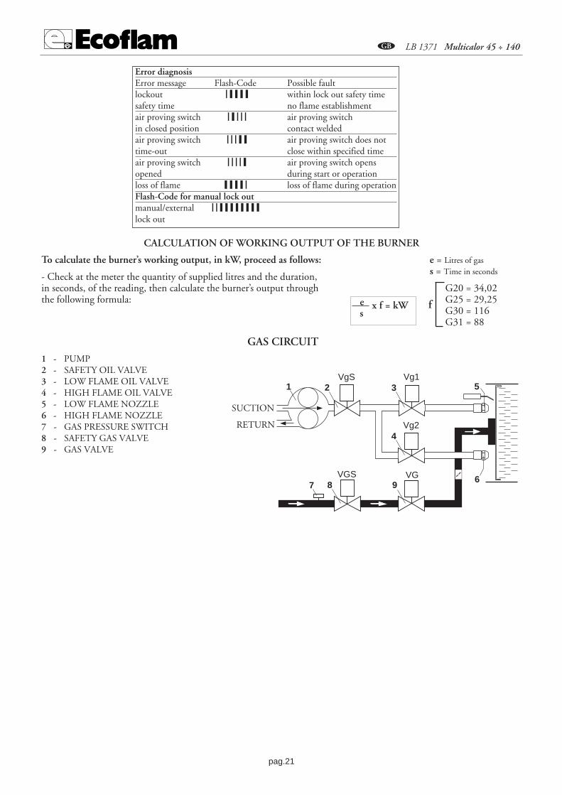
GAS CIRCUIT
SUCTION
RETURN
1 - PUMP2 - SAFETY OIL VALVE3 - LOW FLAME OIL VALVE4 - HIGH FLAME OIL VALVE5 - LOW FLAME NOZZLE6 - HIGH FLAME NOZZLE7 - GAS PRESSURE SWITCH8 - SAFETY GAS VALVE9 - GAS VALVE
Error diagnosisError message Flash-Code Possible faultlockout ❘ ❙ ❙ ❙ ❙ within lock out safety timesafety time no flame establishmentair proving switch ❘ ❙ ❘ ❘ ❘ air proving switchin closed position contact weldedair proving switch ❘ ❘ ❘ ❙ ❙ air proving switch does nottime-out close within specified timeair proving switch ❘ ❘ ❘ ❘ ❙ air proving switch opensopened during start or operationloss of flame ❙ ❙ ❙ ❙ ❘ loss of flame during operationFlash-Code for manual lock outmanual/external ❘ ❘ ❙ ❙ ❙ ❙ ❙ ❙ ❙ ❙lock out
To calculate the burner’s working output, in kW, proceed as follows:
- Check at the meter the quantity of supplied litres and the duration, in seconds, of the reading, then calculate the burner’s output through the following formula:
CALCULATION OF WORKING OUTPUT OF THE BURNER
e x f = kWs
e = Litres of gass = Time in seconds
G20 = 34,02G25 = 29,25G30 = 116G31 = 88
f

pag.22
B LB 1371 Multicalor 45 ÷ 140
ADJUSTMENT OF GAS MINIMUM PRESSURE SWITCHUnscrew off and remove cover M. - Set regulator N to a value equal to 60% of gasnominal feed pressure (i.e. for nat. gas nom. pressure = 20 mbar, set regulator to a valueof 12 mbar; for L.P.G. nom. pressure of G30/G31- 30/37 mbar, set regulator to a valueof 18 mbar).Screw up cover M
ADJUSTMENT OF THE AIR PRESSURE SWITCHUnscrew screws A and B and remove cover C.- Set the pressure switch to the minimumby turning regulator D to position 1. - Start the burner and keep in low flame running, while checking that combustion iscorrect. Through a small cardboard, progressively obstruct the air intake until to obtaina CO2 increase of 0,5÷0,8% or else, if a pressure gauge is available, connected to pres-sure port E, until reaching a pressure drop of 1mbar (10 mm of W.G.). - Slowly increa-se the adjustment value of the air pressure switch until to have the burner lockout.Remove the obstruction from the air intake, screw on the cover C and start the burnerby pressing the control box rearm button.Note: The pressure measured at pressure port E must be within the limits of thepressure switch working range. If not, loose the locking nut of screw F and graduallyturn the same: clockwise to reduce the pressure; counterclockwise to increase. At the end tighten the locking nut.
2,55
10 15
50
25
35
30
4045
20
0,4
0,6 0,9
3,0
1,5
2,1
1,8
2,42,7
1,2
I
L
MN
A
B
CD
E
F
GH
ADJUSTEMENT OF THE COMBUSTION AIR
Remove cover to gain access to the adjusting cams.The cams are to be adjustedthrough the suitable key provided for. Description:
I - Limit switch for air damper “High Flame” position adjustment (Max. power)
II - Limit switch for the air damper position at burner’s shut downIII - Limit switch for air damper “Low Flame” position adjustment
(Min. power)V - Limit switch "NOT USED".
LANDIS & STAEFA SQN 31 251A2700 AIR DAMPER MOTOR
MANUAL RELEASESWITCH
2
SELECTOR
0
AUTO
0 = operating elements locked in an intermediate position
= operation on maximum capacity
= operation on minimum capacity
AUTO = automatic operation
13
AIR ADJUSTMENT

pag.23
B LB 1371 Multicalor 45 ÷ 140
OPERATION OF BURNER WITH LIGHT-OIL FUEL Gas/Light-oil dual burners must always be adjusted for a first light-oil ignition. After having installed the burner, checkthe following points: Feeding voltage and protection fuses - Motor connections – The correctness of pipe system lengthand its sealing – The type of fuel, which must be suitable for the burner - The connections of boiler’s thermostats andthe safety devices – The direction of motors rotation – The correct calibration of motors protections – The nozzles flowrate must be suitable for the boiler’s output – At the end, fit a manometer on the pump itself. When all the above con-ditions are met, it will, then, be possible to proceed with the burner start-up. Switch the burner ON. The control boxwill power up the fuel pump and the fan’s motor, thus allowing a prepurging of the combustion chamber at the maxi-mum air flow rate. At the end of prepurging, the servomotor will set up to the light-oil Low flame position, whilst thecontrol box powers up the ignition transformer and the “Safety” and “Low flame” solenoid val-ves.If the burner ignites normally, after a safety time of 3 sec. the control box will power off theignition transformer and after 10 secs. operates the air damper’s servomotor, bringing the bur-ners to High flame operation. In case of faulty ignition, the control box will shut down theburner to lockout position within 3 sec. In this case, the burner must be reset manually, bypressing the lockout enable pushbutton on the control box itself. In order to obtain a correctcombustion, it will be necessary to adjust the Low and High flame by following the instructions showed at pages 8÷9(Air servomotor and firing head adjustment). During the adjusting phase, it will be possible to manually switch, backand forth, from Low flame to High flame through the High-Low flame manual switch. When all the adjusting opera-tions are achieved, leave the switch in High flame position. For a correct reading and calibration, carry out the combu-stion analysis in the chimney.
0
12
0 - STOP1 - GASOLIO2 - GAS
LIGHT-OIL
ADJUSTING THE MAXIMUM CAPACITY OF THE BURNERPosition the selector, situated on the control panel, on position maximum power and proceed as follows:Adjusting the maximum gas flow rate: - proceed as stated in the regulating the solenoid valves until you achieve thecorrect gas flow, as established by analyzing the combustion process. Eventually adjust the gas flow rate using a suitableallen wrench, alter the position of the cam(3) guide blade; if you screw it down, the flow rate is reduced; if you unscrewit, the flow rate increases.Adjusting the maximum air flow rate: Eventually adjust this position acting on the screw “1 “, after loosening nut “ 2“. Tighten the nut “2” in place once again.
ADJUSTING THE MINIMUM CAPACITY OF THE BURNERPosition the selector, situated on the control panel, on position minimum power and proceed as follows: Adjusting the minimum gas flow rate: using a suitable Allen wrench, alter the position of the cam(3) guide blade; ifyou screw it down, the flow rate is reduced; if you unscrew it, the flow rate increases.Adjusting the minimum air flow rate: adjust on limit switch for air damper “Low Flame” position adjustment.
ADJUSTING THE INTERMEDIATE BURNER CAPACITIES Using the selector, start the servomotor (closing or opening) and position on 0 to stop the stroke; the adjustment ismade as outlined below. Repeat the operation for the other cam points.Adjusting the intermediate gas flow rates: using a suitable Allen wrench, alter the position of the cam(3) guide blade; ifyou screw it down, the flow rate is reduced; if you unscrew it, the flow rate increases.

pag.24
B LB 1371 Multicalor 45 ÷ 140
H
H
Bitubo dalla sommità del serbatoio
Bitubo in aspirazione
H (m)Dall'asse
della pompa
Lunghezza tubazioni
ø 10mm
ø 12mm
00,5123
3,5
323640485660
909090909090
ø 12mm
ø 14mm
666558453225
909080806552
AS 67AN 77
(m)AJ 6(m)
252118105-
706254382010
666052402519
909090805845
RSA 60(m)
RSA 125(m)
ø 10mm
ø 12mm
ø 10mm
ø 12mm
ø 15mm
-4853637378
-99
100100100100
-2225293436
-4651617176
-100100100100100
H (m)Dall'asse
della pompa
Lunghezza tubazioni
ø 10mm
ø 12mm
00,5123
3,5
ø 12mm
ø 14mm
AS 67AN 77
(m)AJ 6(m)
RSA 60(m)
RSA 125(m)
ø 10mm
ø 12mm
ø 10mm
ø 12mm
ø 15mm
43373222127
887867462515
2018151063
41363122127
1008977532917
The correct length of pipes is calculated by summing up the length of all vertical and horizontal right sections and bends. The staticsuction head will be the distance between the non-return valve and the burner’s pump axle. The depression must not be greater than 0.45 bar; should it be higher, some damage could occur to the pump, with consequentincrease in mechanical noises and ,eventually, a failure.
MAXIMUM LENGTH OF SUCTION LINES FOR TWO-PIPE SYSTEM
Two-pipe lift system
Two-pipe siphon feed system PIPE LENGTH
PIPE LENGTH
NOZZLE PUMP PRESSURE (bar)GPH 10 11 12 13 14 15 162,50 9,50 9,97 10,41 10,83 11,24 11,64 12,023,00 11,40 11,96 12,49 13,00 13,49 13,96 14,423,50 13,30 13,95 14,57 15,17 15,74 16,29 16,834,00 15,20 15,94 16,65 17,33 17,99 18,62 19,234,50 17,10 17,94 18,73 19,50 20,24 20,95 21,635,00 19,00 19,93 20,82 21,67 22,48 23,27 24,045,50 20,90 21,92 22,90 23,83 24,73 25,60 26,446,00 22,80 23,92 24,98 26,00 26,98 27,93 28,846,50 23,70 25,91 27,06 28,17 29,23 30,26 31,257,00 26,60 27,90 29,14 30,33 31,48 32,58 33,657,50 28,50 29,90 31,22 32,50 33,73 34,91 36,058,30 31,54 33,08 34,55 35,97 37,32 38,63 39,909,50 36,10 37,87 39,55 41,17 42,72 44,22 45,6710,50 40,06 41,73 43,74 45,41 47,20 48,90 50,5012,00 45,60 47,80 50,00 52,00 54,00 55,90 57,7013,80 52,40 55,00 57,50 59,80 62,10 64,20 66,3015,30 58,10 61,00 63,70 66,30 68,80 71,10 73,6017,50 66,50 69,80 72,90 75,80 78,70 81,50 84,1019,50 74,10 77,70 81,20 84,50 87,70 90,80 93,7021,50 81,70 85,70 89,50 93,20 96,70 100,10 103,4024,00 91,20 95,70 99,90 104,00 107,90 111,70 115,40GPH OUTPUT kg/h
NOZZLE FLOW RATE (DELAVAN B - MONARCH PLP)

pag.25
B LB 1371 Multicalor 45 ÷ 140
1° STADIO GASOLIO
ASPIRAZIONE
RITORNO
VgS
Vg2
Vg11 2 3
4
5
6VGVGS987
2° STADIO GASOLIO
ASPIRAZIONE
RITORNO
VgS
Vg2
Vg11 2 3
4
5
6VGVGS987
4 - VACUUM GAUGE PORT 5 - PRESSURE ADJUSTMENT6 - TO NOZZLE
The pump is adjusted during testing and inspection to 12 bar. VERIFY: - That piping system is perfectly sealed; - That the useof hoses is avoided whenever is possible (use copper pipes preferably); - That depression is not greater than 0,45 bar, to avoidpump’s cavitation; - That check valve is suitably designed for the duty; The pump pressure is set at a value of 12 bar during thetesting of burners. Before starting the burner, bleed the air in the pump through the gauge port. Fill the piping with light-oil tofacilitate the pump priming. Start the burner and check the pump feeding pressure. In case the pump priming does not take placeduring the first prepurging, with a consequent, subsequent lock-out of the burner, rearm the burner’s lock-out to restart, bypushing the button on the control box. If, after a successful pump priming, the burner locks-out after the prepurging, due to a fuelpressure drop in the pump, rearm the burner’s lock-out to restart the burner. Do not allow the pump to work without oil for morethan three minutes. NOTE: Before starting the burner, check that the return pipe is open. An eventual obstruction coulddamage the pump sealing device.
5
12
6
4
3
PRIMING AND ADJUSTMENT OF OIL PUMP
6 5
4
3 3
3
SUNTECSUNTEC
P V
21
SUNTEC AN 67 C DANFOSS RSA 60-RSA 125 SUNTEC AN 77
6 5
4
3 3
3
SUNTECSUNTEC
P V
21
LIGHT-OIL CIRCUIT
A - HOSEB - OIL FILTER C - OIL COCK 1 - PUMP2 - SAFETY OIL VALVE3 - LOW FLAME OIL VALVE4 - HIGH FLAME OIL VALVE5 - LOW FLAME NOZZLE6 - HIGH FLAME NOZZLE7 - GAS PRESSURE SWITCH8 - SAFETY GAS VALVE9 - GAS VALVE
SUCTION
RETURN
SUCTION
RETURN
Adjust light-oil pressure and airflow for the low flame.The burner will operate in Low flame until the switch set againto High flame. The control box will then enable the Highflame, through the full opening of the air damper. The High flame pressure, in normal operation, must be set to12-15 bar (check on the manometer connected to the pressureport). Adjust the combustion air through the head adjustinglever.
A
A
B C
1 - INLET 2 - RETURN 3 - BLEED AND PRESSURE GAUGE PORT

pag.26
B LB 1371 Multicalor 45 ÷ 140
ADJUSTING THE FIRING HEAD
The adjustment of the combu-stion head position is carried outin order toobtain the best combustion effi-ciency. When installed for smalloutput operations,the head shall be adjusted back.For maximum operation the position is fully forward. Steps: loosen the locking screw of A lever. Move the lever to the needed position. Tighten back the locking screw.
A
min. max.
A
min. max.
MULTICALOR45-70-100
MULTICALOR120-140
NOZZLE CLEANING AND REPLACEMENT
Use only the suitable box wrench provided for thisoperation to remove the nozzle, taking care to notdamage the electrodes. Fit the new nozzle with thesame care.Note: Always check the position of electrodes afterhaving replaced the nozzle (see illustration). Awrong position could cause ignition troubles.
5÷6 mm
3÷4 mm
2 fiamme
The control of the ionisation current shall be carried out by plugging a microamperometerwith full scale at 50 µA (D.C.) in series with the UV-cell. If the ioinisation current is toolow verify the connection between phase and neutral of the burner and the grounding ofthe burner itself. Usually, the value of the ionisation current is > 20 µA. Minimum required ionisation current: 3 µA
LGB 22
QRA
AGQ
1.1A
27 1
2
SW
SW
BL
BL
FLAME DETECTION SYSTEM CHECK
Microamperometer full scale 50 µA
SW = BLACKBL = BLU
13 mm.120 Metano
13 mm.
140 Metano
120 G.P.L.
140 G.P.L.
POSITION OPEN
POSITION CLOSSED
POSITIONING THE DISC FOR NATURAL GAS AND L.P.G. MULTICALOR 120/140
L.P.G.
L.P.G.
Natural Gas
Natural Gas

pag.27
B LB 1371 Multicalor 45 ÷ 140
0 12
0I
12
6
3
54
87
0
OIL GAS
0
AUTO
1 - Fuse2 - Termal lock-out lamp3 - Light-oil working lamp4 - Gas working lamp5 - Selector : 0 Loking of devoices for operating at intermediate outputs
Operation at max. output
Operation at min. output
AUTO Automatic operation
6 - Main switch I / O7 - Selector : 0 / Light-oil / Gas8 - Lockout disable push button
PGM EXIT
PGM EXIT
PGM EXIT
I
0
REMOVING THE BLAST TUBE
DESCRIPTION OF CONTROL PANEL
0 12
1 - Fuse2 - Termal lock-out lamp3 - Light-oil working lamp4 - Gas working lamp5 - Selector : 0 Loking of devoices for operating at intermediate outputs
Operation at max. output
Operation at min. output
AUTO Automatic operation
6 - Main switch I / O7 - Selector : 0 / Light-oil / Gas8 - Lockout disable push button9 - Modulating unit RWF 40
PGM EXIT
PGM EXIT
854
6
2
9
1
0
AUTO
0I
K6
RWF 40
PGMPGM EXITEXIT
7 3
0
OIL GAS
GASOIL
Multicalor PR
Multicalor MD

pag.28
B LB 1371 Multicalor 45 ÷ 140
RWF 40 MICROPROCESSOR REGULATOR
Display:analog input 1(actual value)
Display: Set point SP1
Decrease value
Programming key
Manual operation
Auxiliary contact
Increase value
EXIT key.
Burner operation
Reduce powerCLOSE/1st Stage
Increase powerOPEN/2nd Stage
Two-stage operation
Description of display and keys on the RWF 40 microprocessor regulatorThe figure shows the normal display indicating
the actual value and the programmed setpoint, and equally important,
gives the meaning of thesingle keys and indicator Leds.
Configuration level
User Level
Normal display
Parameters level
PGM
PGM
PGM
PGM PGMPGM
PGM PGM
PGM PGM
min 2s
min 2s
min 2s
Exit
PROGRAMMING LEVELS

pag.29
B LB 1371 Multicalor 45 ÷ 140
SETTING PARAMETERSWhen the burner is ignited all displays of the regulator light up. The set point display will blink for about 10 seconds. The valuein the upper field of the display (red) indicates the actual value. The value in the lower field of the display (green) indicates the setpoint currently programmed.
CHANGING THE SET POINT
To change the set point, proceed as follows: ---- Press the PGMPGM button to access the user level. SP1* will appear in the lower display---- Change the value of set point SP1 using the t and s keys.�e �. ---- After a 2 second delay the value set is stored automatically –To return to normal display press EXITEXIT. ** The value of SP1 depends on the value set previously in configuration level C111.
SETTING PID PARAMETERSPID parameters are factory set to standard mean values. The operation of the regulator can be self-adapted to suit the system byactivating the “tunE” function. The regulator will set the PID parameters automatically. To activate the “tunE” function proceedas follows: ---- With the burner in operation, press PGM PGM + �. ---- the caption “tunE*” will blink in the display. – When “tunE”stops blinking, the self-adaptation routine has been completed. ---- Confirm the computed parameters by pressing the � key for 2seconds. ** The “tunE” function cannot be activated in Manual mode, or when the burner is off. The PID parameters can be corrected manually from the parameters level, working on the proportional band Pb1, the derivati-ve action time dt and the integral action time rt. To change parameters Pb1, dt and rt, proceeds as follows: ---- Press the PGMPGM button to access the parameters level. ---- To move fromone parameter to the next, press PGMPGM . ---- When Pb1 is displayed, the value can be increased or decreased using the s and t keys. ----Confirm the changed parameters by pressing PGMPGM. ---- If confirmation is not given within 2 seconds the value will be stored auto-matically. ---- Press PGMPGM to access the next parameter. ---- When dt is displayed, repeat the procedure described above. ---- Press PGMto access the next parameter. ---- When rt is displayed, repeat the procedure above. ---- To return to normal display press EXITEXIT.
DIFFERENTIAL SETTING FOR IGNITION AND SHUTOFFThe regulator allows the selection of an adjustable switching differential that establishes burner ignition and shutoff values.HYS1 indicates the lower ignition limit, below which the regulator switches the burner to maximum power. HYS3 indicatesthe upper shutoff limit, above which the regulator switches the burner off. To set HYS1 and HYS3 proceed as follows: ---- Pressthe PGMPGM key to access the parameters level. ---- To move from one parameter to the next, press PGMPGM . ---- When HYS1 is displayed(burner ignition differential-stage II), increase or decrease the value using the � and � keys. ---- Confirm the changed parameters bypressing PGMPGM. ---- If confirmation is not given within 2 seconds the value will be stored automatically. ---- Press PGMPGM to access thenext parameter. ---- When HYS2 is displayed (burner shutoff differential-stage II), repeat the procedure described above. ---- PressPGMPGM to access the next parameter. ---- When HYS3 is displayed (upper shutoff differential) repeat the procedure described above. ---- To return to normal display press EXITEXIT.
MANUAL/AUTOMATIC MODETo access “MANUAL” mode, press and hold EXITEXIT for at least 5 seconds. Manual mode can only be selected when the burner isin operation. It is deactivated automatically when the burner shuts off. When the LED above the hand symbol is alight, the regu-lator is in manual mode and the position of the servocontrol can be changed using the � and � keys. The LEDS on the front ofthe regulator indicate whether the servocontrol OPEN or CLOSE command is currently active. Pressing the � key the servocon-trol OPENS. Pressing the � key the servocontrol CLOSES. To select automatic mode press and hold EXITEXIT for at least 5 seconds.The LED above the hand symbol goes out and the regulator reverts to automatic.
CLIMATIC COMPENSATION
The RWF 40 regulator can be set with the set point interlocked to the external probe. To select this operating mode, proceed asfollows: ---- Connect the required probe as in the wiring diagram. ---- Change the regulator settings. When using an external probethe regulator must be set as follows: ---- Press the PGMPGM key to access the configuration level. When the caption C111 (XXXX) isdisplayed, use the � key to access the second figure (XXXX). Use the � key to select the type of probe (XX3X). ---- Confirm thechange of parameters by pressing PGMPGM. If this is not done within 2 seconds, the value is stored automatically ---- Press PGMPGM toaccess the configuration level. When the display reads C112 (XXXX), use the � key to access the second figure (XXXX). Pressthe � key to set the type of probe (XX3X). ---- Confirm the changed parameters by pressing PGMPGM. ---- If confirmation is not givenwithin 2 seconds the value will be stored automatically. ---- To return to normal display press EXITEXIT. To establish the heating curve, proceed as follows: ---- Press PGMPGM to access the parameters level. ---- Press PGMPGM to move from one parameter to the next. ---- When the letter H isdisplayed (heating curve gradient), increase or decrease the value using the � and � keys. ---- Confirm the changed parameters bypressing PGMPGM. ---- If confirmation is not given within 2 seconds the value will be stored automatically. ---- To return to normal display press EXITEXIT.

pag.30
B LB 1371 Multicalor 45 ÷ 140
PROBE CONNECTION DIAGRAMS
SPH
60
80
100
0
20
40
SPL
120
140
160
20 15 10 5 0 -20-15-10-517.5 12.5 7.5 2.5 -2.5 -17.5-12.5-7.5
0.20.40.60.811.21.41.61.822.22.42.62.833.23.43.63.84
External temperature (iC)
Hea
tin
g c
urv
e g
rad
ien
t (H
)
PARAMETERIZATIONB
oile
r te
mp
erat
ure
set
po
int
(iC
)
Cod.S704
Cod. S721Cod.S731
S731/1S731/2S731/3S731/4
Cod.S720/1
Connection for probeQAE2..(passive probe)Water probeConfiguration codeC111 = 9XXX
Connection for probeFT-TP/..(passive probe)(Degusa probe)Configuration codeC111 = 5XXX
Connection for probe QBE620-P..(active probes)Configuration code C111 = GXXXS731 - 0…4 bar / 0…400 kPa QBE620-P4 S731/1 - 0…10 bar / 0…1 MPa QBE620-P10 S731/2 - 0…16 bar / 0…1.6 Mpa QBE620-P16 S731/3 - 0…25 bar / 0…2.5 MPa QBE620-P25 S731/4 - 0…40 bar / 0…4 MPa QBE620-P40
Connection for probeQAC22 (passive probe)Configuration code C111 = XX3XC112 = XX1X
1 2 3 4
RWF 40
B M
G1+ M1
QAE22A
1 2 3 4
RWF 40
B M
B9 M9
QAC2..
1 2 3 4
RWF 40
GL M
G+ M1
OBE620-P..U1
G- U1

pag.31
B LB 1371 Multicalor 45 ÷ 140
- Situation - The number 1999 blinks in the display as the actual value, with the set point value displayed normally.
- Cause - The real value is not being measured. This means that the upper or lowerlimit of the measurement range on analog input 1 (real value) has been exceeded.
- Remedy - Check the electrical connections and the state of the probe. If the probeis faulty, the regulator will not indicate the real value of the physical quantity monitored. This will result in automatic shutdown (failsafe), deactivation of theself-adapt function and inhibition of manual operation. The response of the auxiliary contact will depend on the configuration of parameter C113.
- Situation - The number 1999 blinks in the display as the actual value, with tAshowing in the set point field.
- Cause - The external temperature is not being measured. This means that theupper or lower limit of the measurement range on analog input 3 (real value) hasbeen exceeded.
- Remedy - Check the electrical connections and the state of the probe. If the probeis faulty, the regulator will not indicate the real value.
- Situation - The number 1999 blinks in the display as the actual value, with SP .Eshowing in the set point field.
- Cause - The external set point value is not being measured. This means that theupper or lower limit of the measurement range on analog input 2 (real value) hasbeen exceeded.
- Remedy - Check the electrical connections and the external set point signal. If theprobe is faulty, the regulator will not indicate the real value of the physical quantitymonitored. This will result in automatic shutdown (failsafe), deactivation of the self-adapt function and inhibition of manual operation.
ERROR/FAULT INDICATIONNUMBERS BLINKING IN DISPLAY
Analog input 1 (actual value)Pt1000, 2-wire, Landis & Staefa IEC 751
5FT-TP/… (passive probe)
Ni1000, 2-wire, Landis & Staefa9QAE2 … (passive probe - water probe)
Standard Signal DC 0…10 V QBE620P…(active probe - pressure probe) G
C111 – C112 INPUT CONFIGURATION INDICATIONS
Analog Input 3 (external temperature)No function (probe not active) 0External probe Pt 1000, 2-wire,
1QAC22 (passive probe)
AUXILIARY CONTACT, TYPE OF REGULATOR, SET POINT “SP1”BLOCK C112. Parameter configuration
Set point “SP1”Set point SP1 - data input from keys 0Set point SP1 - interlocked to external probe (configure) 1
pag.32
B LB 1371 Multicalor 45 ÷ 140
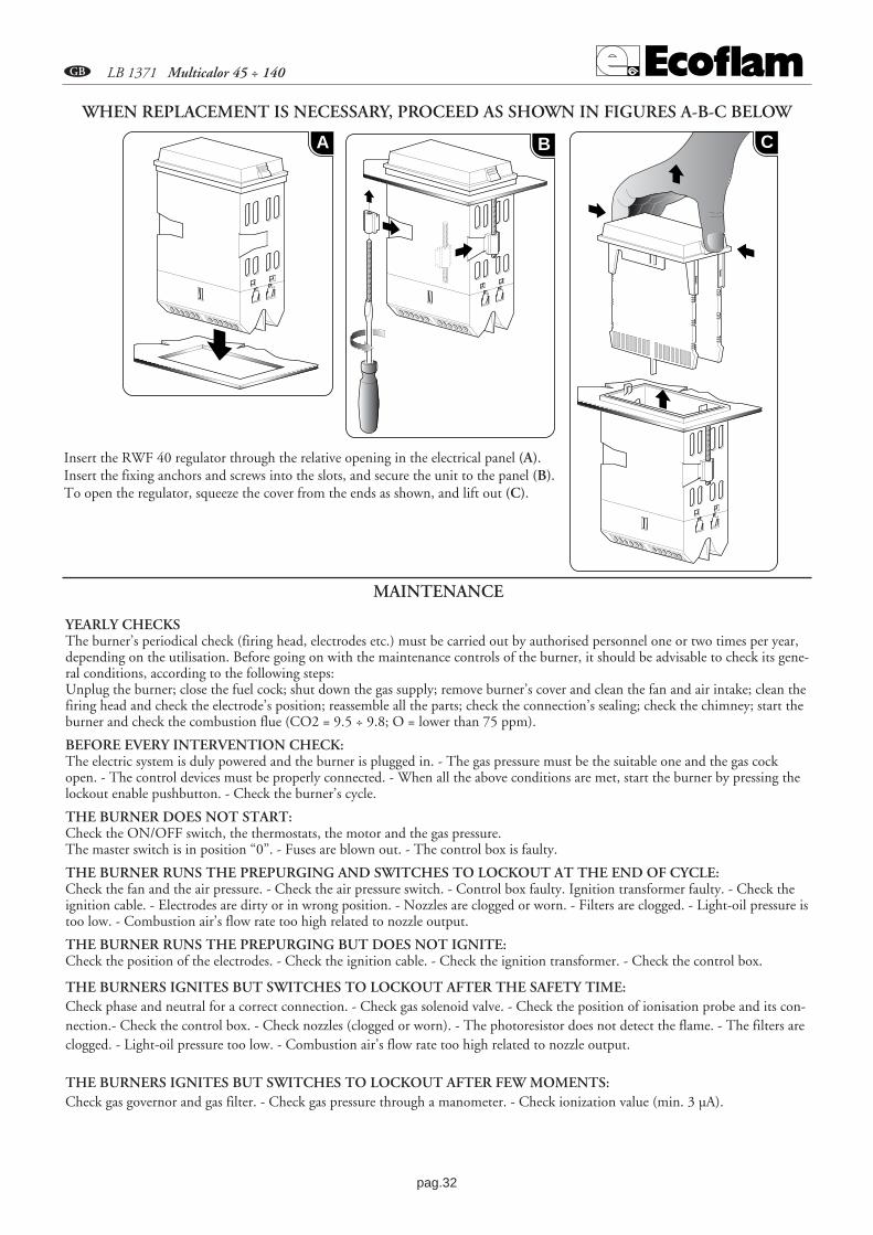
Insert the RWF 40 regulator through the relative opening in the electrical panel (A). Insert the fixing anchors and screws into the slots, and secure the unit to the panel (B). To open the regulator, squeeze the cover from the ends as shown, and lift out (C).
WHEN REPLACEMENT IS NECESSARY, PROCEED AS SHOWN IN FIGURES A-B-C BELOW
MAINTENANCE
YEARLY CHECKSThe burner’s periodical check (firing head, electrodes etc.) must be carried out by authorised personnel one or two times per year,depending on the utilisation. Before going on with the maintenance controls of the burner, it should be advisable to check its gene-ral conditions, according to the following steps:Unplug the burner; close the fuel cock; shut down the gas supply; remove burner’s cover and clean the fan and air intake; clean thefiring head and check the electrode’s position; reassemble all the parts; check the connection’s sealing; check the chimney; start theburner and check the combustion flue (CO2 = 9.5 ÷ 9.8; O = lower than 75 ppm).
BEFORE EVERY INTERVENTION CHECK:The electric system is duly powered and the burner is plugged in. - The gas pressure must be the suitable one and the gas cockopen. - The control devices must be properly connected. - When all the above conditions are met, start the burner by pressing thelockout enable pushbutton. - Check the burner’s cycle.
THE BURNER DOES NOT START:Check the ON/OFF switch, the thermostats, the motor and the gas pressure. The master switch is in position “0”. - Fuses are blown out. - The control box is faulty.
THE BURNER RUNS THE PREPURGING AND SWITCHES TO LOCKOUT AT THE END OF CYCLE:Check the fan and the air pressure. - Check the air pressure switch. - Control box faulty. Ignition transformer faulty. - Check theignition cable. - Electrodes are dirty or in wrong position. - Nozzles are clogged or worn. - Filters are clogged. - Light-oil pressure istoo low. - Combustion air’s flow rate too high related to nozzle output.
THE BURNER RUNS THE PREPURGING BUT DOES NOT IGNITE:Check the position of the electrodes. - Check the ignition cable. - Check the ignition transformer. - Check the control box.
THE BURNERS IGNITES BUT SWITCHES TO LOCKOUT AFTER THE SAFETY TIME:Check phase and neutral for a correct connection. - Check gas solenoid valve. - Check the position of ionisation probe and its con-nection.- Check the control box. - Check nozzles (clogged or worn). - The photoresistor does not detect the flame. - The filters areclogged. - Light-oil pressure too low. - Combustion air’s flow rate too high related to nozzle output.
THE BURNERS IGNITES BUT SWITCHES TO LOCKOUT AFTER FEW MOMENTS:Check gas governor and gas filter. - Check gas pressure through a manometer. - Check ionization value (min. 3 µA).
A B C

pag.33
B LB 1371 Multicalor 45 ÷ 140
Parameter Display Ecoflam setting Ecoflam setting Ecoflam setting (passive probe) (passive probe) (active probe)
QAE22 FT-TP/1000 QBE620-P...Limit value of limit comparator AL 0 0 0Switching differential for limit comparator HYSt 0 0 0Proportional band Pb.1 8 8 1Derivative time dt 20 20 3Integral action time rt 80 80 15Dead band (neutral zone) db 0.5 0.5 0.5Actuator running time (sec.) tt 12 12 12Switch-on threshold burner / stage II HYS1 -2 -2 -0.2Switch-off level stage II HYS2 0 0 0Upper switch-off threshold HYS3 5 5 0.5Response threshold q 0 0 0Heating curve slope H 2 2 2Parallel displacement P 0 0 0
PARAMETERS LANDIS RWF 40
Parameter Display Ecoflam setting(passive probe) (active probe) QBE620-P...
QAE22 FT-TP/1000 -P4 -P10 -P16 -P25 -P40Analog input 1, 2 and 3; setpoint changeover / shift C111 9030 5030 G000 G000 G000 G000 G000Limit comparator; controller type; setpoint 1; locking C112 0010 0010 0010 0010 0010 0010 0010Unit address; decimal place / unit, signal for out-of-range C113 0110 0110 0110 0110 0110 0110 0110Measured value range start analog input 1 SCL 0 0 0 0 0 0 0Measured value range analog input 1 SCH 100 100 4 10 16 25 40Measured value range analog input 2 SCL2 0 0 0 0 0 0 0Measured value range analog input 2 SCH2 0 0 0 0 0 0 0Lower setpoint limit SPL 60 60 0 0 0 0 0Upper setpoint limit SPH 88 88 4 10 16 25 40Actual value correction,analog input 1 OFF1 0 0 0 0 0 0 0Actual value correction,analog input 2 OFF2 0 0 0 0 0 0 0Actual value correction,analog input 3 OFF3 0 0 0 0 0 0 0Filter time constant for digital filter, dF1 1 1 0 0 0 0 0analog input 1
CONFIGURATION LANDIS RWF 40

pag.34
AB LB 1371 Multicalor 45 ÷ 140
+-
BLAC
K
BLUE
AGQ1
.1A27
RED
BROW
N
BLUE
BLAC
K
3M
PT
PAGI
NA D
I
1M
LINE
LOAD
BLUE
YELLOW-GREEN
BLACK
BROWN
CONT
ROLE
D'ET
ANCH
EITI
CONT
ROL D
E EST
ANQU
IDAD
PRED
ISPO
SICI
ON
PREV
U PO
UR LE
PRED
ISPO
SED
LEKA
GE C
ONTR
OL
PRED
ISPO
SIZI
ONE
CONT
ROLL
O DI
TENU
TA
TP
N
N
S3 B4T2T1
S3 B4T2T1
L1
L1
PT
STC
PT
STS
0001
0203
0405
0607
0809
A
0001
0203
0405
0607
0809
B C D E
A B C D E
S.p.A.
IND.
MO
DIFI
CA
SOST
.DA
SOST
.IL
IND.
MO
D.
PROPRIETA' RISERVATA DELLA DITTA ECOFLAM S.p.A.
DATA
-FIR
MA
DATA
FIRMA
CONT
ROLL
ATO
DESC
RIZI
ONE
MO
DIFI
CA
DISE
GNAT
O
DATA
FIRMA
COMUNICARE A TERZI IL CONTENUTO DEL PRESENTE. A TERMINE DI LEGGE E' VIETATO RIPRODURRE O
CONT
ROLL
O D
I TEN
UTA
APPA
RECC
HIAT
URA
UFF.T
ECNI
CO-S
ETTO
RE EL
ETTR
ICO
DENO
MIN
AZIO
NE
SIST
. RIV
ELAZ
.CO
DICE
MO
TORI
DUTT
ORE BE
M43
149
MUL
TICA
LOR
45 -
70 (
gas P
R-ga
solio
AB)
LA
NDIS
SQ
N 31
.251
A270
0
LAND
IS L
GB 2
2.33
0A27
PRED
ISPO
STO
UV10
-06-
2004
UV
MV
UV
W
KMV
RS
TN
O
FMV
SALFU
LAND
IS LG
B 22.3
30A2
73
12
75
46
119
810
1231
32LA
NDIS
SQN3
1.251
A270
0N
13
25
46
78
SPA
TV
NR
ST
107
65
98
11
GAS (
2)GA
SOLIO
(1)
1/2
380V
220V
YVg2
YVg1
YVgS
HLg
HLG
FMV
95 96
MP
Z
HLB
T
FMV
97 98
KA
SAgG
12
30
YVG
YVG
S
T2N
T1L1
S3
SPG
min
L1T1
NT2
S3
SAM
A
12
30
1412
13
KAx
GRAY
RED
WHI
TE
BLAC
K
BLUE
YELL
OW
/GRE
EN
BRO
WN
50 H
z 400
V
N
PE
R TS
Q
HL1
HLB
B5O
RANG
E
BRO
WN
WHI
TE
RED
GRAY
VIO
LET
T6T7T8T2 T1S3B44
PIN
WIE
LAND
FO
R CO
NNEC
TIO
N
4 PI
N W
IELA
ND F
OR
CONN
ECTI
ON
CONT
ROL
PANE
L (G
AS O
PERA
TIO
N )
CONT
ROL
PANE
L (O
IL O
PERA
TIO
N )
1516
pos 0
: ARR
ESTO
/ ST
OP
pos 3
: AUT
OM
ATIC
O/A
UTO
MAT
IC/A
UTO
MAT
IQUE
pos 2
: BAS
SA F
IAM
MA/
LOW
FLA
ME/
1e A
LLUR
E/BA
JA L
LAM
A
pos 1
: ALT
A FI
AMM
A/HI
GH F
LAM
E/2e
ALL
URE/
ALTA
LLA
MA
SAM
A
12
30
SWIT
CH M
ANUA
L-AU
TOM
ATIC
CONM
UTAD
OR
MAN
UAL-
AUTO
MAT
ICO
COM
MUT
ATO
RE M
ANUA
LE-A
UTO
MAT
ICO
INTE
RRRU
PTEU
R M
ANUE
L-AU
TOM
ATIQ
UE
17-0
6-20
04

pag.35
AB LB 1371 Multicalor 45 ÷ 140
IND.
MO
DIFI
CA
SOST
.DA
SOST
.IL
IND.
MO
D.
PROPRIETA' RISERVATA DELLA DITTA ECOFLAM S.p.A.
DATA
-FIR
MA
DATA
FIRMA
CONT
ROLL
ATO
DESC
RIZI
ONE
MO
DIFI
CA
DISE
GNAT
O
DATA
FIRMA
COMUNICARE A TERZI IL CONTENUTO DEL PRESENTE. A TERMINE DI LEGGE E' VIETATO RIPRODURRE O
CONT
ROLL
O D
I TEN
UTA
APPA
RECC
HIAT
URA
UFF.T
ECNI
CO-S
ETTO
RE EL
ETTR
ICO
DENO
MIN
AZIO
NE
SIST
. RIV
ELAZ
.CO
DICE
MO
TORI
DUTT
ORE
PAGI
NA D
I
QIN
TERR
UTTO
RE G
ENER
ALE C
ON FU
SIBI
LE
ZFI
LTRO
ANT
IDIS
TURB
O
FUFU
SIBI
LE
MP
MOT
ORE P
OMPA
MV
MOT
ORE V
ENTI
LATO
RE
TVTR
ASFO
RMAT
ORE
UVFO
TOCE
LLUL
A
FMV
RELE
' TER
MIC
O M
OTOR
E VEN
TILA
TORE
HLB
LAM
PADA
DI B
LOCC
O
HLG
LAM
PADA
GAS
HLg
LAM
PADA
GAS
OLIO
KMV
CONT
ATTO
RE M
OTOR
E VEN
TILA
TORE
SAB
DEVI
ATOR
E ALT
A-BA
SSA
FIAM
MA
SAL
INTE
RRUT
TORE
DI L
INEA
SPA
PRES
SOST
ATO
ARIA
AIR
PRES
SURE
SWIT
CHPR
ESSO
STAT
AIR
PRES
OSTA
TO A
IRE
OIL O
R LA
MP
TEM
OIN
MAZ
OUT
ESPI
A GA
SOLE
O
WOR
KING
SWIT
CHIN
TERR
UPTE
UR D
E LIG
NEIN
TERR
UPTO
R DE
LINE
A
REM
OTE C
ONTR
OL SW
ITCH
(FAN
MOT
OR)
CONT
ACTE
UR M
OTEU
R VE
NTILA
TEUR
TELE
RRUP
TOR
MOT
OR V
ENTI
LATO
R
LOCK
-OUT
LAM
PLA
MPE
DE S
ECUR
ITE
ESPI
A DE
BLO
QUEO
MOT
OR TH
ERM
AL R
ELAY
(FAN
MOT
OR)
RELA
IS TH
ERM
IQUE
MOT
EUR
VENT
ILATE
UR
RELE
' TER
MIC
O M
OTOR
VEN
TILA
DOR
GAS L
AMPE
LAM
PE D
E GAZ
ESPI
A GA
S
MOT
OR FA
NM
UTEU
R VE
NTILA
TEUR
MOT
OR V
ENTI
LADO
R
UV C
ELL
CELL
ULE
UVFO
TOCE
LULA
IGNI
TION
TRAN
SFOR
MER
TRAN
SFOR
MAT
EUR
D'AL
LUM
AGE
TRAN
SFOR
MAD
OR
ANTJ
AMM
ING
FILT
ERFI
LTRE
ANT
IPAR
ASIT
ESFI
LTRO
DE P
ROTE
CION
ANT
IDIS
TURB
IO
MAI
N SW
ITCH
WIT
H FU
SEIN
TERR
UPTE
UR G
ENER
AL A
VEC
FUSI
BLE
INTE
RRUP
TOR
GENE
RAL C
ON FU
SIBL
E
OIL P
UMP
MOT
ORM
OTEU
R PO
MPE
MOT
OR B
OMBA
FUSE
FUSI
BLE
FUSI
BLE
HIGH
-LOW
FLAM
E SW
ITCH
INTE
RRUP
TEUR
GRA
NDE/
PETI
RE A
LLUR
ECO
NMUT
ADOR
DE A
LTA/
BAJA
LLAM
A
ELEC
TROV
ANNE
GAZ
DE S
ECUR
ITE
PRES
SOST
ATO
GAS D
I MIN
IMA
GAS P
RESS
URE S
WIT
CH M
INPR
ESSO
STAT
GAZ
PRE
SSIO
N M
INPR
ESOS
TATO
GAS
DE M
INIM
A PO
T.
SPGm
in
ELET
TROV
ALVO
LA G
ASOL
IO D
I SEC
ONDA
FIAM
MA
SECO
ND ST
AGE O
IL SO
LENO
ID V
ALVE
ELET
TROV
ALVO
LA G
ASOL
IO D
I PRI
MA
FIAM
MA
FIRS
T STA
GE O
IL SO
LENO
ID V
ALVE
ELEC
TROV
ANNE
MAZ
OUT P
ETIT
E ALL
URE
ELEC
TROV
ALVU
LA D
E GAS
OLEO
1^
LLAM
A
ELEC
TROV
ALVU
LA G
AS D
E SEG
URID
AD
ELET
TROV
ALVO
LA G
ASOL
IO D
I SIC
UREZ
ZAEX
TRA
SAFE
TY O
IL SO
LENO
ID V
ALVE
ELEC
TROV
ANNE
MAZ
OUT D
E SEC
URIT
E
ELEC
TROV
ALVU
LA D
E GAS
OLEO
DE S
EGUR
IDAD
ELEC
TROV
ANNE
MAZ
OUT G
RAND
E ALL
URE
ELEC
TROV
ALVU
LA D
E GAS
OLEO
2^
LLAM
A
YVgS
YVg2
YVg1
ELET
TROV
ALVO
LA G
AS D
I PRI
MA
FIAM
MA
FIRS
T STA
GE G
AS SO
LENO
ID V
ALVE
ELEC
TROV
ANNE
GAZ
PET
ITE A
LLUR
EEL
ECTR
OVAL
VULA
GAS
DE 1
^ LL
AMA
HIGH
-LOW
FLAM
E THE
RMOS
TAT
THER
MOS
TAT G
RAND
E-PE
TIRE
ALL
URE
TERM
OSTA
TO D
E ALT
A-BA
JA LL
AMA
ELET
TROV
ALVO
LA G
AS D
I SIC
UREZ
ZAEX
TRA
SAFE
TY G
AS SO
LENO
ID V
ALVE
YVGS
YVG1
TERM
OSTA
TO D
I SIC
UREZ
ZASA
FETY
THER
MOS
TAT
THER
MOS
TAT D
E SEC
URIT
E
TERM
OSTA
TO C
ALDA
IABO
ILER
THER
MOS
TAT
THER
MOS
TAT C
HAUD
IERE
TERM
OSTA
TO C
ALDE
RA
TERM
OSTA
TO D
I ALT
A-BA
SSA
FIAM
MA
INTE
RRUT
ORE O
LIO-G
ASSW
ITCH
HEA
VY O
IL - G
ASIN
TERR
UPTE
UR FU
EL LO
URD
- GAZ
INTE
RRUP
TOR
ACEI
TE P
ESAD
O - G
AZ
TERM
OSTA
TO D
E SEG
URID
AD
STAB
SAgG
STS
STC
SWIT
CH H
EAVY
OIL
- GAS
INTE
RRUP
TEUR
FUEL
LOUR
D - G
AZIN
TERR
UPTO
R AC
EITE
PES
ADO
- GAZ
HIGH
-LOW
FLAM
E THE
RMOS
TAT
THER
MOS
TAT G
RAND
E-PE
TIRE
ALL
URE
TERM
OSTA
TO D
E ALT
A-BA
JA LL
AMA
BOILE
R TH
ERM
OSTA
TTH
ERM
OSTA
T CHA
UDIE
RETE
RMOS
TATO
CAL
DERA
SAFE
TY TH
ERM
OSTA
TTH
ERM
OSTA
T DE S
ECUR
ITE
TERM
OSTA
TO D
E SEG
URID
AD
EXTR
A SA
FETY
GAS
SOLE
NOID
VAL
VEEL
ECTR
OVAN
NE G
AZ D
E SEC
URIT
EEL
ECTR
OVAL
VULA
GAS
DE S
EGUR
IDAD
FIRS
T STA
GE G
AS SO
LENO
ID V
ALVE
ELEC
TROV
ANNE
GAZ
PET
ITE A
LLUR
EEL
ECTR
OVAL
VULA
GAS
DE 1
^ LL
AMA
EXTR
A SA
FETY
OIL
SOLE
NOID
VAL
VEEL
ECTR
OVAN
NE M
AZOU
T DE S
ECUR
ITE
ELEC
TROV
ALVU
LA D
E GAS
OLEO
DE S
EGUR
IDAD
FIRS
T STA
GE O
IL SO
LENO
ID V
ALVE
ELEC
TROV
ANNE
MAZ
OUT P
ETIT
E ALL
URE
ELEC
TROV
ALVU
LA D
E GAS
OLEO
1^
LLAM
A
SECO
ND ST
AGE O
IL SO
LENO
ID V
ALVE
ELEC
TROV
ANNE
MAZ
OUT G
RAND
E ALL
URE
ELEC
TROV
ALVU
LA D
E GAS
OLEO
2^
LLAM
A
GAS P
RESS
URE S
WIT
CH M
INPR
ESSO
STAT
GAZ
PRE
SSIO
N M
INPR
ESOS
TATO
GAS
DE M
INIM
A PO
T.
AIR
PRES
SURE
SWIT
CHPR
ESSO
STAT
AIR
PRES
OSTA
TO A
IRE
WOR
KING
SWIT
CHIN
TERR
UPTE
UR D
E LIG
NEIN
TERR
UPTO
R DE
LINE
A
HIGH
-LOW
FLAM
E SW
ITCH
INTE
RRUP
TEUR
GRA
NDE/
PETI
RE A
LLUR
ECO
NMUT
ADOR
DE A
LTA/
BAJA
LLAM
A
REM
OTE C
ONTR
OL SW
ITCH
(FAN
MOT
OR)
CONT
ACTE
UR M
OTEU
R VE
NTILA
TEUR
TELE
RRUP
TOR
MOT
OR V
ENTI
LATO
R
OIL L
AMP
TEM
OIN
MAZ
OUT
ESPI
A GA
SOLE
O
GAS L
AMP
LAM
PE D
E GAZ
ESPI
A GA
S
LOCK
-OUT
LAM
PLA
MPE
DE S
ECUR
ITE
ESPI
A DE
BLO
QUEO
MOT
OR TH
ERM
AL R
ELAY
(FAN
MOT
OR)
RELA
IS TH
ERM
IQUE
MOT
EUR
VENT
ILATE
URRE
LE' T
ERM
ICO
MOT
OR V
ENTI
LADO
R
UV C
ELL
CELL
ULE
UVFO
TOCE
LULA
IGNI
TION
TRAN
SFOR
MER
TRAN
SFOR
MAT
EUR
D'AL
LUM
AGE
TRAN
SFOR
MAD
OR
MOT
OR FA
NM
UTEU
R VE
NTILA
TEUR
MOT
OR V
ENTI
LADO
R
OIL P
UMP
MOT
ORM
OTEU
R PO
MPE
MOT
OR B
OMBA
FUSE
FUSI
BLE
FUSI
BLE
ANTJ
AMM
ING
FILT
ERFI
LTRE
ANT
IPAR
ASIT
ESFI
LTRO
DE P
ROTE
CION
ANT
IDIS
TURB
IO
MAI
N SW
ITCH
WIT
H FU
SEIN
TERR
UPTE
UR G
ENER
AL A
VEC
FUSI
BLE
INTE
RRUP
TOR
GENE
RAL C
ON FU
SIBL
E
HLBT
LAM
PADA
DI B
LOCC
O TE
RMIC
OTH
ERM
AL LO
CK-O
UT LA
MP
LAM
PE D
E THE
RMAL
DE S
ECUR
ITE
ESPI
A DE
BLO
QUEO
REL
E TER
MIC
O
RELE
'KA
RELA
YRE
LAIS
RELE
'
TP
TP
KAx
RELE
'RE
LAY
RELA
ISRE
LE'
0001
0203
0405
0607
0809
A
0001
0203
0405
0607
0809
B C D E
A B C D E
S.p.A.
BEM
4314
9M
ULTI
CALO
R 45
- 70
(GAS
PR
- GAS
OLI
O A
B)LA
NDIS
SQ
N 31
.251
A270
0
LAND
IS L
GB 2
2.33
0A27
UV10
-06-
2004
2/2
SPG
min
YELLOW-GREEN
YVG
YVG
S
T6T8
L1N
B5T7 DU
NGS
VPS 5
04
BROWN
BLACK
BLUE
T1N
L1S3
T2
YVG
SYV
G
L1
YELLOW-GREEN
BLACK
DUNG
S VD
K 200
-A114
13BROWN
BLUE
3
SPG
min
S3N
T1T2

pag.36
AB LB 1371 Multicalor 45 ÷ 140
8
9
Mu
ltic
alo
r 45
P
R G
as /
P A
B L
ight
oil
51
10
113
1
4 5 6
715
38
40
41
4546
47
48
444342
28
DIS
CO
AN
TE
RIO
RE
SO
LO P
ER
ME
TA
NO
FR
ON
T D
ISK
FO
R
NA
TU
RA
L G
AS
ON
LY
DIS
QU
E A
NT
ER
IEU
R P
OU
R
GA
Z N
AT
. SE
ULE
ME
NT
DIS
CO
AN
TE
RIO
R S
OLO
PA
RA
GA
S N
AT
.
A B C D
27
36
37
29
30
3231
33
34
35
39
2
FIND
ER
49 50
PG
ME
XIT
1312
14
18
19 2023
2621
22
0I
GA
SO
IL
160
AU
TO
0
17
2425
0
AU
TO
0I
K6
RW
F 4
0PG
MP
GM
EX
ITE
XIT
0OIL
GA
S
GA
SO
IL
20 2122 23 19X

pag.37
AB LB 1371 Multicalor 45 ÷ 140
8
9
Mu
ltic
alo
r 70
- 1
00P
R-M
D G
as /
P A
B L
ight
oil
51
10
113
1
4 5 6
715
38
40
41
4546
47
48
444342
28
1312
14
18
19 2023
2621
22
0I
GA
SO
IL
16
39
2
FIND
ER
PG
ME
XIT
0
AU
TO
0
49 50
DIS
CO
AN
TE
RIO
RE
SO
LO P
ER
ME
TA
NO
FR
ON
T D
ISK
FO
R
NA
TU
RA
L G
AS
ON
LY
DIS
QU
E A
NT
ER
IEU
R P
OU
R
GA
Z N
AT
. SE
ULE
ME
NT
DIS
CO
AN
TE
RIO
R S
OLO
PA
RA
GA
S N
AT
.
A B C D
27
36
37
29
30
3231
33
34
35
17
2425
0
AU
TO
0I
K6
RW
F 4
0PG
MP
GM
EX
ITE
XIT
0OIL
GA
S
GA
SO
IL
20 2122 23 19X
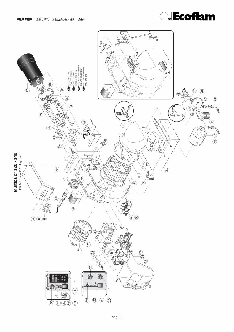
pag.38
AB LB 1371 Multicalor 45 ÷ 140
8
9
Mu
ltic
alo
r 12
0 -
140
PR
-MD
Gas
/ P
AB
Lig
ht o
il
51
10
113
1
4 5 6
715
38
40
41
4546
47
48
444342
28
1312
14
18
19 2023
2621
22
0I
GA
SO
IL
16
39
2
FIND
ER
PG
ME
XIT
0
AU
TO
0
49 50
17
2425
0
AU
TO
0I
K6
RW
F 4
0PG
MP
GM
EX
ITE
XIT
0OIL
GA
S
GA
SO
IL
20 2122 23 19X
DIS
CO
AN
TE
RIO
RE
SO
LO P
ER
ME
TA
NO
FR
ON
T D
ISK
FO
R
NA
TU
RA
L G
AS
ON
LY
DIS
QU
E A
NT
ER
IEU
R P
OU
R
GA
Z N
AT
. SE
ULE
ME
NT
DIS
CO
AN
TE
RIO
R S
OLO
PA
RA
GA
S N
AT
.
A B C D
35
37
29
30
3231
33
34
35
27

pag.39
A LB 1371 Multicalor 45 ÷ 140
Multicalor 45N° DESCRIZIONE codice
1 - PRESSOSTATO ARIA DUNGS LGW10 A2P Q1202 - GRUPPO PRESE ARIA GRPA1003 - SPINA WIELAND 6 poli E2264 - COPERCHIO BRUCIATORE BFC09151/0115 - VETRINO BFC020046 - CORNICE OBLO BFC020067 - MOTORE 550 W M1698 - VENTOLA 220 x 98 BFV10155/0019 - CONVOGLIATORE BFC08202/01710 - SURPRESSORE BFC08055/00111 - CASSETTO BFC04160/01112 - ADATTATORE LANDIS AGQ1.1A27 E1202/1113 - ZOCCOLO LANDIS A402
SATRONIC A41714 - APPARECCHIATURA LANDIS LGB22 A130/1
LANDIS LMG 22 A153/2SATRONIC DMG 972 A162/01
15 - TRASFORMATORE COFI 1020 CM T105/116 - CONTATTORE MC9.10 R603/117 - CONTATTORE MOTORE POMPA MC9.10 R603/118 - RELE’ TERMICO Lovato RF9 1,4-2 R51019 - INTERRUTTORE DI LAVORO cod.40100I1509 R102020 - COMMUTATORE ALTA/BASSA FIAMMA R1020/521 - COMMUTATORE GAS/GASOLIO R1020/522 - LAMPADA EL/N-SC4 Elettrospring E151023 - PORTA FUSIBILE FUSIT FH-B528 E802/224 - ZOCCOLO RELE FINDER 5534 R90625 - RELE FINDER 5534 R71226 - FILTRO ANTIDISTURBO S132/427 - CAVI ACCENSIONE TC BFE01402/1
TL BFE01402/228 - FOTOCELLULA LANDIS QRA2 A20529 - GRUPPO ELETTRODI ACCENSIONE GREL10630 - TUBO SUPPORTO TESTA BFT13102/00131 - ASTA REGOLAZIONE TESTA BFA08001/00132 - TESTA DI COMBUSTIONE TC BFT13101/101
TL BFT13101/20133 - DISCO POSTERIORE BFD02010/40134 - DISCO ANTERIORE BFD0701435 - PORTA UGELLI BFC1105236 - GRUPPO TESTA TC GRTT0100/725
TL GRTT0100/72637 - BOCCAGLIO TC BFB04005/103
TL BFB04005/20338 - FLANGIA ISOMART BFG03002/139 - MOTORIDUTTORE LANDIS SQN 30.251A2700 M21240 - POMPA GASOLIO SUNTEC AN 67 C P11341 - GIUNTO MP501/342 - RACCORDO PER FLESSIBILE TN 6x1500 S923/243 - TUBI FLESSIBILI TN 10X1200 S90544 - FILTRO GASOLIO art. 70301-01P S117/145 - MOTORE POMPA 200 W M111/146 - CONDENSATORE 6.3 µF C107/347 - VALVOLA GASOLIO DELTA 1/8 F.84 V42048 - BOBINA DELTA V502/249 - VALVOLA GASOLIO PARKER SCEM VE131 V175/250 - BOBINA PARKER V51651 - SILENZIATORE (Opzionale) GRSIL0252 - CENTRALINA MODULANTE LANDIS RWF 40 E1215
TC = TESTA CORTA TL = TESTA LUNGA

pag.40
B LB 1371 Multicalor 45 ÷ 140
TC = SHORT HEAD TL = LONG HEAD
Multicalor 45N° DESCRIPTION code
1 - AIR PRESSURE SWITCH DUNGS LGW10 A2P Q1202 - AIR INTAKE SET GRPA1003 - PLUG WIELAND 6 pin E2264 - COVER BFC09151/0115 - GLASS BFC020046 - VIEWING WINDOW BFC020067 - MOTOR 550 W M1698 - FAN 220 x 98 BFV10155/0019 - AIR CONVEYOR BFC08202/01710 - FAN SCOOP BFC08055/00111 - AIR INTAKE BFC04160/01112 - ADAPTER LANDIS AGQ1.1A27 E1202/1113 - CONTROL BOX BASE LANDIS A402
SATRONIC A41714 - CONTROL BOX LANDIS LGB22 A130/1
LANDIS LMG 22 A153/2SATRONIC DMG 972 A162/01
15 - IGNITION TRANSFORMER COFI 1020 CM T105/116 - REMOTE CONTROL SWITCH MC9.10 R603/117 - REMOTE CONTROL SWITCH (PUMP) MC9.10 R603/118 - MOTOR THERMAL RELAY Lovato RF9 1,4-2 R51019 - MAIN SWITCH cod.40100I1509 R102020 - HIGH/LOW/AUTO FLAME SELECTOR R1020/521 - GAS/LIGHT-OIL SELECTOR R1020/522 - LAMP EL/N-SC4 Elettrospring E151023 - FUSE SUPPORT FUSIT FH-B528 E802/224 - RELAY BASE FINDER 5534 R90625 - RELAY FINDER 5534 R71226 - ANTIJAMMING FILTER S132/427 - IGNITION CABLE TC BFE01402/1
TL BFE01402/228 - UV CELL LANDIS QRA2 A20529 - IGNITION ELECTRODES SET GREL10630 - PIPE BFT13102/00131 - ROD BFA08001/00132 - FIRING HEAD TC BFT13101/101
TL BFT13101/20133 - REAR DISC BFD02010/40134 - FRONT DISC BFD0701435 - NOZZLE HOLDER BFC1105236 - INNER ASSEMBLY TC GRTT0100/725
TL GRTT0100/72637 - BLAST TUBE TC BFB04005/103
TL BFB04005/20338 - GASKET BFG03002/139 - AIR DAMPER MOTOR LANDIS SQN 30.251A2700 M21240 - OIL PUMP SUNTEC AN 67 C P11341 - COUPLING MP501/342 - NIPPLE TN 6x1500 S923/243 - HOSES TN 10X1200 S90544 - OIL FILTER art. 70301-01P S117/145 - PUMP MOTOR 200 W M111/146 - CONDENSATOR 6.3 µF C107/347 - OIL VALVE DELTA 1/8 F.84 V42048 - COIL DELTA V502/249 - OIL VALVE PARKER SCEM VE131 V175/250 - COIL PARKER V51651 - SILENCER (Opzionale) GRSIL0252 - MODULATING UNIT LANDIS RWF 40 E1215
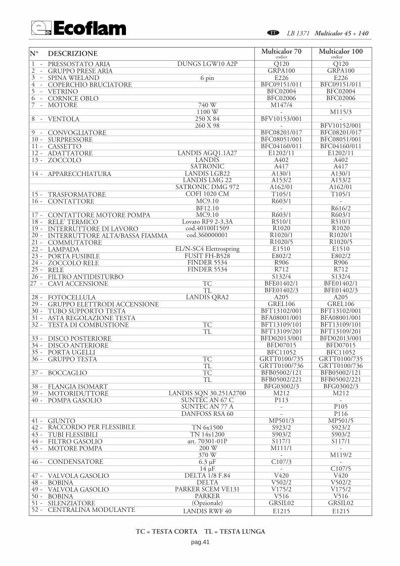
pag.41
A LB 1371 Multicalor 45 ÷ 140
Multicalor 70 Multicalor 100N° DESCRIZIONE codice codice
1 - PRESSOSTATO ARIA DUNGS LGW10 A2P Q120 Q1202 - GRUPPO PRESE ARIA GRPA100 GRPA1003 - SPINA WIELAND 6 pin E226 E2264 - COPERCHIO BRUCIATORE BFC09151/011 BFC09151/0115 - VETRINO BFC02004 BFC020046 - CORNICE OBLO BFC02006 BFC020067 - MOTORE 740 W M147/4 -
1100 W - M115/38 - VENTOLA 250 X 84 BFV10153/001 -
260 X 98 - BFV10152/0019 - CONVOGLIATORE BFC08201/017 BFC08201/01710 - SURPRESSORE BFC08051/001 BFC08051/00111 - CASSETTO BFC04160/011 BFC04160/01112 - ADATTATORE LANDIS AGQ1.1A27 E1202/11 E1202/1113 - ZOCCOLO LANDIS A402 A402
SATRONIC A417 A41714 - APPARECCHIATURA LANDIS LGB22 A130/1 A130/1
LANDIS LMG 22 A153/2 A153/2SATRONIC DMG 972 A162/01 A162/01
15 - TRASFORMATORE COFI 1020 CM T105/1 T105/116 - CONTATTORE MC9.10 R603/1 -
BF12.10 - R616/217 - CONTATTORE MOTORE POMPA MC9.10 R603/1 R603/118 - RELE’ TERMICO Lovato RF9 2-3,3A R510/1 R510/119 - INTERRUTTORE DI LAVORO cod.40100I1509 R1020 R102020 - INTERRUTTORE ALTA/BASSA FIAMMA cod.360000001 R1020/1 R1020/121 - COMMUTATORE R1020/5 R1020/522 - LAMPADA EL/N-SC4 Elettrospring E1510 E151023 - PORTA FUSIBILE FUSIT FH-B528 E802/2 E802/224 - ZOCCOLO RELE FINDER 5534 R906 R90625 - RELE FINDER 5534 R712 R71226 - FILTRO ANTIDISTURBO S132/4 S132/427 - CAVI ACCENSIONE TC BFE01402/1 BFE01402/1
TL BFE01402/3 BFE01402/328 - FOTOCELLULA LANDIS QRA2 A205 A20529 - GRUPPO ELETTRODI ACCENSIONE GREL106 GREL10630 - TUBO SUPPORTO TESTA BFT13102/001 BFT13102/00131 - ASTA REGOLAZIONE TESTA BFA08001/001 BFA08001/00132 - TESTA DI COMBUSTIONE TC BFT13109/101 BFT13109/101
TL BFT13109/201 BFT13109/20133 - DISCO POSTERIORE BFD02013/001 BFD02013/00134 - DISCO ANTERIORE BFD07015 BFD0701535 - PORTA UGELLI BFC11052 BFC1105236 - GRUPPO TESTA TC GRTT0100/735 GRTT0100/735
TL GRTT0100/736 GRTT0100/73637 - BOCCAGLIO TC BFB05002/121 BFB05002/121
TL BFB05002/221 BFB05002/22138 - FLANGIA ISOMART BFG03002/3 BFG03002/339 - MOTORIDUTTORE LANDIS SQN 30.251A2700 M212 M21240 - POMPA GASOLIO SUNTEC AN 67 C P113 -
SUNTEC AN 77 A - P105DANFOSS RSA 60 - P116
41 - GIUNTO MP501/3 MP501/542 - RACCORDO PER FLESSIBILE TN 6x1500 S923/2 S923/243 - TUBI FLESSIBILI TN 14x1200 S903/2 S903/244 - FILTRO GASOLIO art. 70301-01P S117/1 S117/145 - MOTORE POMPA 200 W M111/1 -
370 W - M119/246 - CONDENSATORE 6.3 µF C107/3 -
14 µF - C107/547 - VALVOLA GASOLIO DELTA 1/8 F.84 V420 V42048 - BOBINA DELTA V502/2 V502/249 - VALVOLA GASOLIO PARKER SCEM VE131 V175/2 V175/250 - BOBINA PARKER V516 V51651 - SILENZIATORE (Opzionale) GRSIL02 GRSIL0252 - CENTRALINA MODULANTE LANDIS RWF 40 E1215 E1215
TC = TESTA CORTA TL = TESTA LUNGA
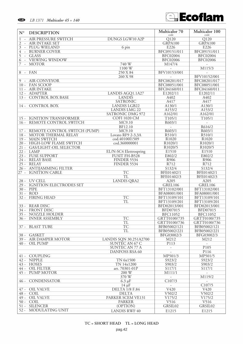
pag.42
B LB 1371 Multicalor 45 ÷ 140
Multicalor 70 Multicalor 100N° DESCRIPTION code code
1 - AIR PRESSURE SWITCH DUNGS LGW10 A2P Q120 Q1202 - AIR INTAKE SET GRPA100 GRPA1003 - PLUG WIELAND 6 pin E226 E2264 - BURNER COVER BFC09151/011 BFC09151/0115 - GLASS BFC02004 BFC020046 - VIEWING WINDOW BFC02006 BFC020067 - MOTOR 740 W M147/4 -
1100 W - M115/38 - FAN 250 X 84 BFV10153/001 -
260 X 98 - BFV10152/0019 - AIR CONVEYOR BFC08201/017 BFC08201/01710 - FAN SCOOP BFC08051/001 BFC08051/00111 - AIR INTAKE BFC04160/011 BFC04160/01112 - ADAPTER LANDIS AGQ1.1A27 E1202/11 E1202/1113 - CONTROL BOX BASE LANDIS A402 A402
SATRONIC A417 A41714 - CONTROL BOX LANDIS LGB22 A130/1 A130/1
LANDIS LMG 22 A153/2 A153/2SATRONIC DMG 972 A162/01 A162/01
15 - IGNITION TRANSFORMER COFI 1020 CM T105/1 T105/116 - REMOTE CONTROL SWITCH MC9.10 R603/1 -
BF12.10 - R616/217 - REMOTE CONTROL SWITCH (PUMP) MC9.10 R603/1 R603/118 - MOTOR THERMAL RELAY Lovato RF9 2-3,3A R510/1 R510/119 - MAIN SWITCH cod.40100I1509 R1020 R102020 - HIGH-LOW FLAME SWITCH cod.360000001 R1020/1 R1020/121 - GAS/LIGHT-OIL SELECTOR R1020/5 R1020/522 - LAMP EL/N-SC4 Elettrospring E1510 E151023 - FUSE SUPPORT FUSIT FH-B528 E802/2 E802/224 - RELAY BASE FINDER 5534 R906 R90625 - RELAY FINDER 5534 R712 R71226 - ANTIJAMMING FILTER S132/4 S132/427 - IGNITION CABLE TC BFE01402/1 BFE01402/1
TL BFE01402/3 BFE01402/328 - UV CELL LANDIS QRA2 A205 A20529 - IGNITION ELECTRODES SET GREL106 GREL10630 - PIPE BFT13102/001 BFT13102/00131 - ROD BFA08001/001 BFA08001/00132 - FIRING HEAD TC BFT13109/101 BFT13109/101
TL BFT13109/201 BFT13109/20133 - REAR DISC BFD02013/001 BFD02013/00134 - FRONT DISC BFD07015 BFD0701535 - NOZZLE HOLDER BFC11052 BFC1105236 - INNER ASSEMBLY TC GRTT0100/735 GRTT0100/735
TL GRTT0100/736 GRTT0100/73637 - BLAST TUBE TC BFB05002/121 BFB05002/121
TL BFB05002/221 BFB05002/22138 - GASKET BFG03002/3 BFG03002/339 - AIR DAMPER MOTOR LANDIS SQN 30.251A2700 M212 M21240 - OIL PUMP SUNTEC AN 67 C P113 -
SUNTEC AN 77 A - P105DANFOSS RSA 60 - P116
41 - COUPLING MP501/3 MP501/542 - NIPPLE TN 6x1500 S923/2 S923/243 - HOSES TN 14x1200 S903/2 S903/244 - OIL FILTER art. 70301-01P S117/1 S117/145 - PUMP MOTOR 200 W M111/1 -
370 W - M119/246 - CONDENSATOR 6.3 µF C107/3 -
14 µF - C107/547 - OIL VALVE DELTA 1/8 F.84 V420 V42048 - COIL DELTA V502/2 V502/249 - OIL VALVE PARKER SCEM VE131 V175/2 V175/250 - COIL PARKER V516 V51651 - SILENCER (OPTION) GRSIL02 GRSIL0252 - MODULATING UNIT LANDIS RWF 40 E1215 E1215
TC = SHORT HEAD TL = LONG HEAD
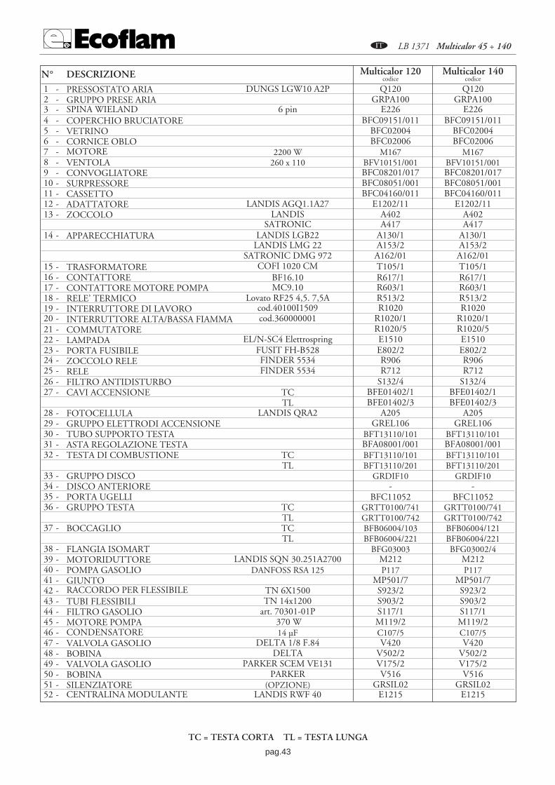
pag.43
A LB 1371 Multicalor 45 ÷ 140
Multicalor 120 Multicalor 140N° DESCRIZIONE codice codice
1 - PRESSOSTATO ARIA DUNGS LGW10 A2P Q120 Q1202 - GRUPPO PRESE ARIA GRPA100 GRPA1003 - SPINA WIELAND 6 pin E226 E2264 - COPERCHIO BRUCIATORE BFC09151/011 BFC09151/0115 - VETRINO BFC02004 BFC020046 - CORNICE OBLO BFC02006 BFC020067 - MOTORE 2200 W M167 M1678 - VENTOLA 260 x 110 BFV10151/001 BFV10151/0019 - CONVOGLIATORE BFC08201/017 BFC08201/01710 - SURPRESSORE BFC08051/001 BFC08051/00111 - CASSETTO BFC04160/011 BFC04160/01112 - ADATTATORE LANDIS AGQ1.1A27 E1202/11 E1202/1113 - ZOCCOLO LANDIS A402 A402
SATRONIC A417 A41714 - APPARECCHIATURA LANDIS LGB22 A130/1 A130/1
LANDIS LMG 22 A153/2 A153/2SATRONIC DMG 972 A162/01 A162/01
15 - TRASFORMATORE COFI 1020 CM T105/1 T105/116 - CONTATTORE BF16.10 R617/1 R617/117 - CONTATTORE MOTORE POMPA MC9.10 R603/1 R603/118 - RELE’ TERMICO Lovato RF25 4,5. 7,5A R513/2 R513/219 - INTERRUTTORE DI LAVORO cod.40100I1509 R1020 R102020 - INTERRUTTORE ALTA/BASSA FIAMMA cod.360000001 R1020/1 R1020/121 - COMMUTATORE R1020/5 R1020/522 - LAMPADA EL/N-SC4 Elettrospring E1510 E151023 - PORTA FUSIBILE FUSIT FH-B528 E802/2 E802/224 - ZOCCOLO RELE FINDER 5534 R906 R90625 - RELE FINDER 5534 R712 R71226 - FILTRO ANTIDISTURBO S132/4 S132/427 - CAVI ACCENSIONE TC BFE01402/1 BFE01402/1
TL BFE01402/3 BFE01402/328 - FOTOCELLULA LANDIS QRA2 A205 A20529 - GRUPPO ELETTRODI ACCENSIONE GREL106 GREL10630 - TUBO SUPPORTO TESTA BFT13110/101 BFT13110/10131 - ASTA REGOLAZIONE TESTA BFA08001/001 BFA08001/00132 - TESTA DI COMBUSTIONE TC BFT13110/101 BFT13110/101
TL BFT13110/201 BFT13110/20133 - GRUPPO DISCO GRDIF10 GRDIF1034 - DISCO ANTERIORE - -35 - PORTA UGELLI BFC11052 BFC1105236 - GRUPPO TESTA TC GRTT0100/741 GRTT0100/741
TL GRTT0100/742 GRTT0100/74237 - BOCCAGLIO TC BFB06004/103 BFB06004/121
TL BFB06004/221 BFB06004/22138 - FLANGIA ISOMART BFG03003 BFG03002/439 - MOTORIDUTTORE LANDIS SQN 30.251A2700 M212 M21240 - POMPA GASOLIO DANFOSS RSA 125 P117 P11741 - GIUNTO MP501/7 MP501/742 - RACCORDO PER FLESSIBILE TN 6X1500 S923/2 S923/243 - TUBI FLESSIBILI TN 14x1200 S903/2 S903/244 - FILTRO GASOLIO art. 70301-01P S117/1 S117/145 - MOTORE POMPA 370 W M119/2 M119/246 - CONDENSATORE 14 µF C107/5 C107/547 - VALVOLA GASOLIO DELTA 1/8 F.84 V420 V42048 - BOBINA DELTA V502/2 V502/249 - VALVOLA GASOLIO PARKER SCEM VE131 V175/2 V175/250 - BOBINA PARKER V516 V51651 - SILENZIATORE (OPZIONE) GRSIL02 GRSIL0252 - CENTRALINA MODULANTE LANDIS RWF 40 E1215 E1215
TC = TESTA CORTA TL = TESTA LUNGA

pag.44
B LB 1371 Multicalor 45 ÷ 140
Multicalor 120 Multicalor 140N° DESCRIPTION code code
1 - AIR PRESSURE SWITCH DUNGS LGW10 A2P Q120 Q1202 - AIR INTAKE SET GRPA100 GRPA1003 - PLUG WIELAND 6 pin E226 E2264 - BURNER COVER BFC09151/011 BFC09151/0115 - GLASS BFC02004 BFC020046 - VIEWING WINDOW BFC02006 BFC020067 - MOTOR 2200 W M167 M1678 - FAN 260 x 110 BFV10151/001 BFV10151/0019 - AIR CONVEYOR BFC08201/017 BFC08201/01710 - FAN SCOOP BFC08051/001 BFC08051/00111 - AIR INTAKE BFC04160/011 BFC04160/01112 - ADAPTER LANDIS AGQ1.1A27 E1202/11 E1202/1113 - CONTROL BOX BASE LANDIS A402 A402
SATRONIC A417 A41714 - CONTROL BOX LANDIS LGB22 A130/1 A130/1
LANDIS LMG 22 A153/2 A153/2SATRONIC DMG 972 A162/01 A162/01
15 - IGNITION TRANSFORMER COFI 1020 CM T105/1 T105/116 - REMOTE CONTROL SWITCH BF16.10 R617/1 R617/117 - REMOTE CONTROL SWITCH (PUMP) MC9.10 R603/1 R603/118 - MOTOR THERMAL RELAY Lovato RF25 4,5. 7,5A R513/2 R513/219 - MAIN SWITCH cod.40100I1509 R1020 R102020 - HIGH-LOW FLAME SWITCH cod.360000001 R1020/1 R1020/121 - GAS/LIGHT-OIL SELECTOR R1020/5 R1020/522 - LAMP EL/N-SC4 Elettrospring E1510 E151023 - FUSE SUPPORT FUSIT FH-B528 E802/2 E802/224 - RELAY BASE FINDER 5534 R906 R90625 - RELAY FINDER 5534 R712 R71226 - ANTIJAMMING FILTER S132/4 S132/427 - IGNITION CABLE TC BFE01402/1 BFE01402/1
TL BFE01402/3 BFE01402/328 - UV CELL LANDIS QRA2 A205 A20529 - IGNITION ELECTRODES SET GREL106 GREL10630 - PIPE BFT13110/101 BFT13110/10131 - ROD BFA08001/001 BFA08001/00132 - FIRING HEAD TC BFT13110/101 BFT13110/101
TL BFT13110/201 BFT13110/20133 - DISC ASSEMBLY GRDIF10 GRDIF1034 - FRONT DISC - -35 - NOZZLE HOLDER BFC11052 BFC1105236 - INNER ASSEMBLY TC GRTT0100/741 GRTT0100/741
TL GRTT0100/742 GRTT0100/74237 - BLAST TUBE TC BFB06004/103 BFB06004/121
TL BFB06004/221 BFB06004/22138 - GASKET BFG03002/4 BFG03002/439 - AIR DAMPER MOTOR LANDIS SQN 30.251A2700 M212 M21240 - OIL PUMP DANFOSS RSA 125 P117 P11741 - COUPLING MP501/7 MP501/742 - NIPPLE TN 6x1500 S923/2 S923/243 - HOSES TN 14x1200 S903/2 S903/244 - OIL FILTER art. 70301-01P S117/1 S117/145 - PUMP MOTOR 370 W M119/2 M119/246 - CONDENSATOR 14 µF C107/5 C107/547 - OIL VALVE DELTA 1/8 F.84 V420 V42048 - COIL DELTA V502/2 V502/249 - OIL VALVE PARKER SCEM VE131 V175/2 V175/250 - COIL PARKER V516 V51651 - SILENCER (OPTION) GRSIL02 GRSIL0252 - MODULATING UNIT LANDIS RWF 40 E1215 E1215
TC = SHORT HEAD TL = LONG HEAD

pag.45
AB LB 1371 Multicalor 45 ÷ 140

Ecoflam S.p.A.via Roma, 64 - 31023 RESANA (TV) - Italy - tel. 0423/715345 r.a.telefax 0423-715444 (Italy 480009 - Export 480873, 715538).http://www.ecoflam.it - e-mail: [email protected]
AEcoflam S.p.A. si riserva il diritto di apportare ai propri prodotti, senza alcun preavviso, tutte quelle modifiche che riterra utili e/o necessarie, al fine di migliorarne la qualit , senza pregiudicarne le caratteristiche principali.
BEcoflam S.p.A. reserves the right to make, without any prior notice, all those modifications which it deems usefull and/or necessary, in order to improve the quality of its products, without affecting their main features.
CEcoflam S.p.A. se r serve le droit d apporter ses produits, sans aucun avis pr alable, tous ces modifications qu elle jug ra outiles et/ou n cessaires pour en am liorer la qualit , sans en pr juger leurs caract ristiques principales
DEcoflam S.p.A. se reserva el derecho de aportar a sus productos, sin previo aviso, todas aquellas modificaciones que considere oportunas para mejorar su calidad, sin perjudicar sus caracteristicas principales.


