Supporting Brocade 5600 vRouter 4.2R1
CONFIGURATION GUIDE
Brocade 5600 vRouter LAN Interfaces Configuration Guide
53-1004259-0116 May 2016

© 2016, Brocade Communications Systems, Inc. All Rights Reserved.
Brocade, Brocade Assurance, the B-wing symbol, ClearLink, DCX, Fabric OS, HyperEdge, ICX, MLX, MyBrocade, OpenScript, VCS, VDX, Vplane, andVyatta are registered trademarks, and Fabric Vision is a trademark of Brocade Communications Systems, Inc., in the United States and/or in othercountries. Other brands, products, or service names mentioned may be trademarks of others.
Notice: This document is for informational purposes only and does not set forth any warranty, expressed or implied, concerning any equipment,equipment feature, or service offered or to be offered by Brocade. Brocade reserves the right to make changes to this document at any time, withoutnotice, and assumes no responsibility for its use. This informational document describes features that may not be currently available. Contact a Brocadesales office for information on feature and product availability. Export of technical data contained in this document may require an export license from theUnited States government.
The authors and Brocade Communications Systems, Inc. assume no liability or responsibility to any person or entity with respect to the accuracy of thisdocument or any loss, cost, liability, or damages arising from the information contained herein or the computer programs that accompany it.
The product described by this document may contain open source software covered by the GNU General Public License or other open source licenseagreements. To find out which open source software is included in Brocade products, view the licensing terms applicable to the open source software, andobtain a copy of the programming source code, please visit http://www.brocade.com/support/oscd.
Brocade 5600 vRouter LAN Interfaces Configuration Guide2 53-1004259-01
ContentsPreface...........................................................................................................................................................................................................................................................................................7
Document conventions..............................................................................................................................................................................................................................................7Text formatting conventions..........................................................................................................................................................................................................................7Command syntax conventions....................................................................................................................................................................................................................7Notes, cautions, and warnings.....................................................................................................................................................................................................................8
Brocade resources.......................................................................................................................................................................................................................................................8Contacting Brocade Technical Support........................................................................................................................................................................................................... 8
Brocade customers...........................................................................................................................................................................................................................................8Brocade OEM customers..............................................................................................................................................................................................................................9
Document feedback....................................................................................................................................................................................................................................................9
About This Guide.....................................................................................................................................................................................................................................................................11
Loopback Interface...............................................................................................................................................................................................................................................................13Loopback interface overview................................................................................................................................................................................................................................13Examples of loopback interface configuration........................................................................................................................................................................................... 14
Configuring network addresses................................................................................................................................................................................................................ 14IPv6 on the loopback interface..................................................................................................................................................................................................................14
Related commands in other guides.................................................................................................................................................................................................................. 15
Loopback Interface Commands....................................................................................................................................................................................................................................17clear interfaces loopback counters.................................................................................................................................................................................................................... 18interfaces loopback <interface-name>............................................................................................................................................................................................................ 19interfaces loopback <interface-name> address....................................................................................................................................................................................... 20interfaces loopback <interface-name> description <description>....................................................................................................................................................21interfaces loopback <interface-name> ipv6 address............................................................................................................................................................................ 22interfaces loopback <interface-name> ipv6 disable-forwarding.................................................................................................................................................... 24interfaces loopback <interface-name> ipv6 dup-addr-detect-transmits..................................................................................................................................25interfaces loopback <interface-name> ipv6 router-advert.................................................................................................................................................................26show interfaces loopback..................................................................................................................................................................................................................................... 30
Data Plane Interfaces.........................................................................................................................................................................................................................................................33Data plane interfaces overview..........................................................................................................................................................................................................................33Examples of data plane interface configuration.......................................................................................................................................................................................33
Viewing system interfaces..........................................................................................................................................................................................................................33Basic configuration of a data plane interface...................................................................................................................................................................................34Ethernet multinetting..................................................................................................................................................................................................................................... 35IPv6 on data plane interfaces...................................................................................................................................................................................................................36Hardware binding for data plane interfaces......................................................................................................................................................................................36
Data Plane Interfaces Commands.............................................................................................................................................................................................................................39clear interfaces dataplane counters.................................................................................................................................................................................................................40interfaces dataplane <interface-name>........................................................................................................................................................................................................... 41interfaces dataplane <interface-name> address...................................................................................................................................................................................... 42interfaces dataplane <interface-name> bond-group <bondx>.........................................................................................................................................................43interfaces dataplane <interface-name> description <description>.................................................................................................................................................44interfaces dataplane <interface-name> dhcp-options no-rfc3442..............................................................................................................................................45interfaces dataplane <interface-name> dhcpv6-options.....................................................................................................................................................................47interfaces dataplane <interface-name> disable........................................................................................................................................................................................ 48
Brocade 5600 vRouter LAN Interfaces Configuration Guide53-1004259-01 3
interfaces dataplane <interface-name> disable-link-detect.............................................................................................................................................................. 49interfaces dataplane <interface-name> hardware dev-port <port-number>............................................................................................................................50interfaces dataplane <interface-name> hardware firmware-index <firmware-index>...........................................................................................................51interfaces dataplane <interface-name> hardware mac <mac-address>.....................................................................................................................................52interfaces dataplane <interface-name> hardware pci-address <pci-address>.......................................................................................................................53interfaces dataplane <interface-name> hardware pci-function <function-number>........................................................................................................... 55interfaces dataplane <interface-name> hardware pci-slot <slot-number>................................................................................................................................56interfaces dataplane <interface-name> hardware port <port-number>.......................................................................................................................................57interfaces dataplane <interface-name> ip disable-forwarding.........................................................................................................................................................58interfaces dataplane <interface-name> ip enable-proxy-arp............................................................................................................................................................59interfaces dataplane <interface-name> ip pim mode <mode>........................................................................................................................................................ 60interfaces dataplane <interface-name> ip rpf-check...............................................................................................................................................................................61interfaces dataplane <interface-name> ipv6 address........................................................................................................................................................................... 62interfaces dataplane <interface-name> ipv6 disable-forwarding................................................................................................................................................... 64interfaces dataplane <interface-name> ipv6 dup-addr-detect-transmits <num>.................................................................................................................65interfaces dataplane <interface-name> ipv6 router-advert............................................................................................................................................................... 66interfaces dataplane <interface-name> mac <mac-addr>.................................................................................................................................................................. 70interfaces dataplane <interface-name> mtu <mtu>...................................................................................................................................................................................71interfaces dataplane <interface-name> vif <vif-id> dhcp-options no-rfc3442...................................................................................................................... 72interfaces dataplane <interface-name> vif <vif-id> policy qos <name>.......................................................................................................................................74interfaces dataplane <interface-name> vrrp vrrp-group <vrrp-group-id> notify bgp......................................................................................................... 75monitor interfaces dataplane <interface-name> traffic..........................................................................................................................................................................77show interfaces dataplane.....................................................................................................................................................................................................................................78show interfaces dataplane detail........................................................................................................................................................................................................................79show interfaces dataplane <interface-name> brief...................................................................................................................................................................................81show interfaces dataplane <interface-name> physical.........................................................................................................................................................................82Related commands documented elsewhere.............................................................................................................................................................................................83
Ethernet Link Bonding Interface.................................................................................................................................................................................................................................85Ethernet link bonding overview......................................................................................................................................................................................................................... 85Ethernet bonding configuration examples..................................................................................................................................................................................................86
Basic Ethernet bonding................................................................................................................................................................................................................................86Ethernet bonding with VLAN....................................................................................................................................................................................................................87
Ethernet Link Bonding Interface Commands..................................................................................................................................................................................................... 89interfaces bonding <dpFbondx>....................................................................................................................................................................................................................... 90interfaces bonding <dpFbondx> address...................................................................................................................................................................................................... 91interfaces bonding <dpFbondx> description <desc>............................................................................................................................................................................. 93interfaces bonding <dpFbondx> dhcp-options no-rfc3442............................................................................................................................................................ 94interfaces bonding <dpFbondx> dhcpv6-options.................................................................................................................................................................................. 96interfaces bonding <dpFbondx> disable....................................................................................................................................................................................................... 97interfaces bonding <dpFbondx> flow-monitoring.................................................................................................................................................................................. 98interfaces bonding <dpFbondx> ip enable-proxy-arp..........................................................................................................................................................................99interfaces bonding <dpFbondx> ip rip receive <version>..................................................................................................................................................................100interfaces bonding <dpFbondx> ip rip send <version>......................................................................................................................................................................... 101interfaces bonding <interface-name> ipv6 address.............................................................................................................................................................................102interfaces bonding dpFbondx ipv6 ospfv3 area....................................................................................................................................................................................104interfaces bonding dpFbondx ipv6 ospfv3 process process-id instance-id instance-id.............................................................................................. 105interfaces bonding <dpFbondx> lacp-options activity........................................................................................................................................................................ 106interfaces bonding <dpFbondx> lacp-options key................................................................................................................................................................................ 107interfaces bonding <dpFbondx> mac <mac-addr>...............................................................................................................................................................................108
Brocade 5600 vRouter LAN Interfaces Configuration Guide4 53-1004259-01
interfaces bonding <dpFbondx> mode....................................................................................................................................................................................................... 109interfaces bonding <dpFbondx> primary <ifx>.......................................................................................................................................................................................... 110show interfaces bonding..........................................................................................................................................................................................................................................111Related commands documented elsewhere............................................................................................................................................................................................. 112
VLAN Interfaces................................................................................................................................................................................................................................................................... 115VLAN interface overview.......................................................................................................................................................................................................................................115
VLAN operation using virtual interfaces............................................................................................................................................................................................. 115Interface types that support VLAN operation..................................................................................................................................................................................115VLAN operation as opposed to multinetting................................................................................................................................................................................... 115Simultaneous Ethernet and 802.1q operation.................................................................................................................................................................................115Referring to VLAN interfaces in commands....................................................................................................................................................................................116IPv6 support....................................................................................................................................................................................................................................................... 116
Examples of VLAN interface configuration................................................................................................................................................................................................ 116VLAN configuration........................................................................................................................................................................................................................................116IPv6 on VLAN interfaces............................................................................................................................................................................................................................. 117
VLAN Interfaces Commands........................................................................................................................................................................................................................................119interfaces dataplane <interface-name> vif <vif-id>............................................................................................................................................................................... 120interfaces dataplane <interface-name> vif <vif-id> address.............................................................................................................................................................. 121interfaces dataplane <interface-name> vif <vif-id> bridge-group.................................................................................................................................................123interfaces dataplane <interface-name> vif <vif-id> description <description>....................................................................................................................... 125interfaces dataplane <interface-name> vif <vif-id> dhcpv6-options.......................................................................................................................................... 126interfaces dataplane <interface-name> vif <vif-id> disable...............................................................................................................................................................128interfaces dataplane <interface-name> vif <vif-id> disable-link-detect.....................................................................................................................................129interfaces dataplane <interface-name> vif <vif-id> ip disable-forwarding............................................................................................................................... 130interfaces dataplane <interface-name> vif <vif-id> ip enable-proxy-arp....................................................................................................................................131interfaces dataplane <interface-name> vif <vif-id> ip rip receive.................................................................................................................................................. 132interfaces dataplane <interface-name> vif <vif-id> ip rip send....................................................................................................................................................... 133interfaces dataplane <interface-name> vif <vif-id> ip rpf-check................................................................................................................................................... 134interfaces dataplane <interface-name> vif <vif-id> ipv6 address..................................................................................................................................................135interfaces dataplane <interface-name> vif <vif-id> ipv6 disable-forwarding.......................................................................................................................... 137interfaces dataplane <interface-name> vif <vif-id> ipv6 dup-addr-detect-transmits <num>.......................................................................................138interfaces dataplane <interface-name> vif <vif-id> ipv6 mld.......................................................................................................................................................... 140interfaces dataplane <interface-name> vif <vif-id> ipv6 ospfv3....................................................................................................................................................142interfaces dataplane <interface-name> vif <vif-id> ipv6 pim...........................................................................................................................................................143interfaces dataplane <interface-name> vif <vif-id> ipv6 router-advert......................................................................................................................................144interfaces dataplane <interface-name> vif <vif-id> ipv6 unnumbered donor-interface <interface> preferred-address <ipv6-address>
........................................................................................................................................................................................................................................................................ 148interfaces dataplane <interface-name> vif <vif-id> mtu <mtu>.......................................................................................................................................................149interfaces dataplane <interface-name> vif <vif-id> vlan <vlan-id>..................................................................................................................................................151show interfaces dataplane <interface-name> vif <vif-id>...................................................................................................................................................................152Related commands documented elsewhere............................................................................................................................................................................................152
Q-in-Q Interface................................................................................................................................................................................................................................................................. 155Q-in-Q interface overview.................................................................................................................................................................................................................................. 155
Q-in-Q interface features..........................................................................................................................................................................................................................155Packet processing using QoS schedulers....................................................................................................................................................................................... 155
Configuring the Q-in-Q interface................................................................................................................................................................................................................... 156Disabling the interface..................................................................................................................................................................................................................................157Ignoring link state changes........................................................................................................................................................................................................................157Viewing interface queuing..........................................................................................................................................................................................................................157
Brocade 5600 vRouter LAN Interfaces Configuration Guide53-1004259-01 5
Q-in-Q Interface Commands..................................................................................................................................................................................................................................... 159interfaces dataplane <interface-name> vif <vif-id> inner-vlan <inner-vid>..............................................................................................................................160interfaces dataplane <interface-name> vif <vif-id> vlan <outer-vid>.............................................................................................................................................161interfaces dataplane <interface-name> vlan-protocol <ethertype>..............................................................................................................................................162policy qos name <policy-name> shaper vlan <outer-vid>................................................................................................................................................................ 163
IP Unnumbered Interfaces............................................................................................................................................................................................................................................ 165Overview....................................................................................................................................................................................................................................................................... 165
Limitations of the feature........................................................................................................................................................................................................................... 165How unnumbered interfaces work....................................................................................................................................................................................................... 165
Unnumbered interface configuration example........................................................................................................................................................................................165Basic IP unnumbered interface configuration............................................................................................................................................................................... 165
IP Unnumbered Interfaces Commands................................................................................................................................................................................................................ 169interfaces dataplane <interface-name> vif <vif-id> ip unnumbered donor-interface <donor-interface-name> preferred-address <ip-address>
.........................................................................................................................................................................................................................................................................170
L2TPv3 Data Plane Interfaces....................................................................................................................................................................................................................................173Overview........................................................................................................................................................................................................................................................................ 173
LAC-to-LAC tunneling reference model.......................................................................................................................................................................................... 173LAC-to-LNS tunneling reference model.......................................................................................................................................................................................... 174LNS-to-LNS tunneling reference model..........................................................................................................................................................................................174Configuration commands.......................................................................................................................................................................................................................... 174
L2TPv3 configuration examples..................................................................................................................................................................................................................... 175Before you begin............................................................................................................................................................................................................................................ 175Configuring a LAC-to-LAC IPv4 tunnel............................................................................................................................................................................................175Configuring a LAC-to-LAC IPv6 tunnel...........................................................................................................................................................................................180Configuring an LNS-to-LNS IPv4 tunnel........................................................................................................................................................................................183Configuring an LNS-to-LNS tunnel with BGP routes..............................................................................................................................................................186Configuring an LNS-to-LNS tunnel with OSPF routes............................................................................................................................................................ 191Configuring an LNS-to-LNS tunnel with RIP routes................................................................................................................................................................ 195
L2TPv3 Data Plane Interfaces Commands....................................................................................................................................................................................................... 199interfaces l2tpeth <lttpN> l2tp-session encapsulation <encapsulation-method>.............................................................................................................200interfaces l2tpeth <lttpN> l2tp-session local-cookie <cookie-string>........................................................................................................................................201interfaces l2tpeth <lttpN> l2tp-session local-ip <local-ip-address>......................................................................................................................................... 202interfaces l2tpeth <lttpN> l2tp-session local-session-id <id>.......................................................................................................................................................203interfaces l2tpeth <lttpN> l2tp-session local-udp-port <udp-port>..........................................................................................................................................204interfaces l2tpeth <lttpN> l2tp-session remote-cookie <cookie-string>................................................................................................................................205interfaces l2tpeth <lttpN> l2tp-session remote-ip <remote-ip-address>..............................................................................................................................206interfaces l2tpeth <lttpN> l2tp-session remote-session-id <id>................................................................................................................................................. 207interfaces l2tpeth <lttpN> l2tp-session remote-udp-port <udp-port>....................................................................................................................................208interfaces dataplane <interface-name> xconnect l2tpeth <tunnel-interface-name>....................................................................................................... 209interfaces dataplane <interface-name> vif <id> xconnect l2tpeth <tunnel-interface-name>........................................................................................ 210show interfaces <lttpN>...........................................................................................................................................................................................................................................211show l2tpeth................................................................................................................................................................................................................................................................212show l2tpeth <lttpN>...............................................................................................................................................................................................................................................213
Data Plane Interface..........................................................................................................................................................................................................................................................215
List of Acronyms.................................................................................................................................................................................................................................................................217
Brocade 5600 vRouter LAN Interfaces Configuration Guide6 53-1004259-01
Preface∙ Document conventions..................................................................................................................................................................................................... 7∙ Brocade resources...............................................................................................................................................................................................................8∙ Contacting Brocade Technical Support...................................................................................................................................................................8∙ Document feedback........................................................................................................................................................................................................... 9
Document conventionsThe document conventions describe text formatting conventions, command syntax conventions, and important notice formats used inBrocade technical documentation.
Text formatting conventionsText formatting conventions such as boldface, italic, or Courier font may be used in the flow of the text to highlight specific words orphrases.
Format Description
bold text Identifies command names
Identifies keywords and operands
Identifies the names of user-manipulated GUI elements
Identifies text to enter at the GUI
italic text Identifies emphasis
Identifies variables
Identifies document titles
Courier font Identifies CLI output
Identifies command syntax examples
Command syntax conventionsBold and italic text identify command syntax components. Delimiters and operators define groupings of parameters and their logicalrelationships.
Convention Description
bold text Identifies command names, keywords, and command options.
italic text Identifies a variable.
value In Fibre Channel products, a fixed value provided as input to a command option is printed in plain text, forexample, --show WWN.
[ ] Syntax components displayed within square brackets are optional.
Default responses to system prompts are enclosed in square brackets.
{ x | y | z } A choice of required parameters is enclosed in curly brackets separated by vertical bars. You must selectone of the options.
In Fibre Channel products, square brackets may be used instead for this purpose.
x | y A vertical bar separates mutually exclusive elements.
< > Nonprinting characters, for example, passwords, are enclosed in angle brackets.
Brocade 5600 vRouter LAN Interfaces Configuration Guide53-1004259-01 7
Convention Description
... Repeat the previous element, for example, member[member...].
\ Indicates a “soft” line break in command examples. If a backslash separates two lines of a commandinput, enter the entire command at the prompt without the backslash.
Notes, cautions, and warningsNotes, cautions, and warning statements may be used in this document. They are listed in the order of increasing severity of potentialhazards.
NOTEA Note provides a tip, guidance, or advice, emphasizes important information, or provides a reference to related information.
ATTENTIONAn Attention statement indicates a stronger note, for example, to alert you when traffic might be interrupted or the device mightreboot.
CAUTIONA Caution statement alerts you to situations that can be potentially hazardous to you or cause damage to hardware, firmware,software, or data.
DANGERA Danger statement indicates conditions or situations that can be potentially lethal or extremely hazardous to you. Safety labelsare also attached directly to products to warn of these conditions or situations.
Brocade resourcesVisit the Brocade website to locate related documentation for your product and additional Brocade resources.
You can download additional publications supporting your product at www.brocade.com. Select the Brocade Products tab to locate yourproduct, then click the Brocade product name or image to open the individual product page. The user manuals are available in theresources module at the bottom of the page under the Documentation category.
To get up-to-the-minute information on Brocade products and resources, go to MyBrocade. You can register at no cost to obtain a userID and password.
Release notes are available on MyBrocade under Product Downloads.
White papers, online demonstrations, and data sheets are available through the Brocade website.
Contacting Brocade Technical SupportAs a Brocade customer, you can contact Brocade Technical Support 24x7 online, by telephone, or by e-mail. Brocade OEM customerscontact their OEM/Solutions provider.
Brocade customersFor product support information and the latest information on contacting the Technical Assistance Center, go to http://www.brocade.com/services-support/index.html.
If you have purchased Brocade product support directly from Brocade, use one of the following methods to contact the BrocadeTechnical Assistance Center 24x7.
Preface
Brocade 5600 vRouter LAN Interfaces Configuration Guide8 53-1004259-01
Online Telephone E-mail
Preferred method of contact for non-urgentissues:
∙ My Cases through MyBrocade
∙ Software downloads and licensingtools
∙ Knowledge Base
Required for Sev 1-Critical and Sev 2-Highissues:
∙ Continental US: 1-800-752-8061
∙ Europe, Middle East, Africa, and AsiaPacific: +800-AT FIBREE (+800 2834 27 33)
∙ For areas unable to access toll freenumber: +1-408-333-6061
∙ Toll-free numbers are available inmany countries.
Please include:
∙ Problem summary
∙ Serial number
∙ Installation details
∙ Environment description
Brocade OEM customersIf you have purchased Brocade product support from a Brocade OEM/Solution Provider, contact your OEM/Solution Provider for all ofyour product support needs.
∙ OEM/Solution Providers are trained and certified by Brocade to support Brocade® products.
∙ Brocade provides backline support for issues that cannot be resolved by the OEM/Solution Provider.
∙ Brocade Supplemental Support augments your existing OEM support contract, providing direct access to Brocade expertise.For more information, contact Brocade or your OEM.
∙ For questions regarding service levels and response times, contact your OEM/Solution Provider.
Document feedbackTo send feedback and report errors in the documentation you can use the feedback form posted with the document or you can e-mailthe documentation team.
Quality is our first concern at Brocade and we have made every effort to ensure the accuracy and completeness of this document.However, if you find an error or an omission, or you think that a topic needs further development, we want to hear from you. You canprovide feedback in two ways:
∙ Through the online feedback form in the HTML documents posted on www.brocade.com.
∙ By sending your feedback to [email protected].
Provide the publication title, part number, and as much detail as possible, including the topic heading and page number if applicable, aswell as your suggestions for improvement.
Preface
Brocade 5600 vRouter LAN Interfaces Configuration Guide53-1004259-01 9

Preface
Brocade 5600 vRouter LAN Interfaces Configuration Guide10 53-1004259-01

About This GuideThis guide describes how to configure LAN interfaces on the Brocade vRouter (referred to as a virtual router, vRouter, or router in theguide).
Brocade 5600 vRouter LAN Interfaces Configuration Guide53-1004259-01 11

About This Guide
Brocade 5600 vRouter LAN Interfaces Configuration Guide12 53-1004259-01
Loopback Interface∙ Loopback interface overview....................................................................................................................................................................................... 13∙ Examples of loopback interface configuration................................................................................................................................................... 14∙ Related commands in other guides......................................................................................................................................................................... 15
Loopback interface overviewA loopback interface is a special software-only interface that emulates a physical interface and allows the router to “connect” to itself.Packets routed to the loopback interface are rerouted back to the router and processed locally. Packets routed out the loopback interfacebut not destined for the loopback interface are dropped.
The Brocade vRouter supports multiple loopback interfaces. These interfaces, with unique IP addressing, can be used as preferredsource addresses for routing protocols such as BGP. These interfaces can also be configured as null or blackhole interfaces.
The Brocade vRouter supports multiple IPv4 and IPv6 addresses on each loopback interface. These interfaces (lo and lo1 through loN )have unique IP addressing, can be used as preferred source addresses for routing protocols such as BGP, and can be configured as nullor blackhole interfaces.
The loopback interface provides a number of advantages.
∙ As long as the router is functioning, the loopback interface is always up, and so is very reliable. When even only one link to therouter is functioning, the loopback interface can be accessed. The loopback interface thus eliminates the need to try each IPaddress of the router until it finds one that is still up.
∙ Because the loopback interface is always up, a routing session (such as a BGP session) can continue even if the outboundinterface fails.
∙ You can simplify collection of management information by specifying the loopback interface as the interface for sending andreceiving management information such as logs and SNMP traps.
∙ The loopback interface can be used to increase security by filtering incoming traffic with access control rules that specify thelocal interface as the only acceptable destination.
∙ In OSPF, you can advertise a loopback interface as an interface route into the network, regardless of whether physical links areup or down. This increases reliability by allowing traffic to take alternate paths if one or more physical links go down.
∙ In BGP, parallel paths can be configured to the loopback interface on a peer device. These parallel paths provide improved loadsharing and redundancy.
The router automatically creates the loopback interface on startup with an interface name of lo. It also automatically configures theloopback address with standard IP addressing.
∙ According to RFC 5735, the 127.0.0.1/8 IPv4 address is assigned to the loopback address. This address is hidden from theshow command output. Typically, the IPv4 address that is assigned to the loopback device is 127.0.0.1 for IPv4, although anyaddress in the range from 127.0.0.0 through 127.255.255.255 is mapped to it.
∙ According to RFC 3513, the ::1/128 IPv6 address is assigned to the loopback interface.
∙ According to RFC 2606, the localhost domain name is mapped to the loopback addresses.
When configuring the router, it is good practice to take advantage of the reliability of the loopback interface with these practices:
∙ The host name of the router should be mapped to the loopback interface address, rather than to a physical interface.
∙ In OSPF and BGP, the router ID should be set to the loopback address. This prevents a possible dynamic recalculation andreassignment of the loopback address when physical interfaces are added or removed from the system. This action isdisruptive to active BGP and OSPF sessions.
Brocade 5600 vRouter LAN Interfaces Configuration Guide53-1004259-01 13
The Brocade vRouter has extensive support for IPv6, including IPv6 interface addressing. The commands for configuring IPv6 on theloopback interface are given in this chapter. A full description of IPv6 support is provided in the Brocade 5600 vRouter IPv6 SupportReference Guide.
Examples of loopback interface configurationThis section presents the following topics:
∙ Configuring network addresses on page 14
∙ IPv6 on the loopback interface on page 14
Configuring network addressesThe system automatically creates and addresses the loopback interface, so you do not need to configure any additional addressing. Ifyou delete the loopback node, the system re-creates and readdresses the loopback address again the next time the system starts.
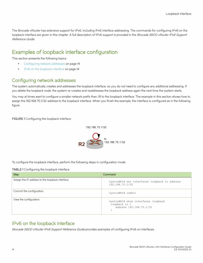
You may at times want to configure a smaller network prefix than /8 to the loopback interface. The example in this section shows how toassign the 192.168.75.1/32 address to the loopback interface. When you finish the example, the interface is configured as in the followingfigure.
FIGURE 1 Configuring the loopback interface
To configure the loopback interface, perform the following steps in configuration mode.
TABLE 1 Configuring the loopback interface
Step Command
Assign the IP address to the loopback interface. vyatta@R1# set interfaces loopback lo address 192.168.75.1/32
Commit the configuration. vyatta@R1# commit
View the configuration. vyatta@R1# show interfaces loopback loopback lo { address 192.168.75.1/32 }
IPv6 on the loopback interfaceBrocade 5600 vRouter IPv6 Support Reference Guide provides examples of configuring IPv6 on interfaces.
Loopback Interface
Brocade 5600 vRouter LAN Interfaces Configuration Guide14 53-1004259-01
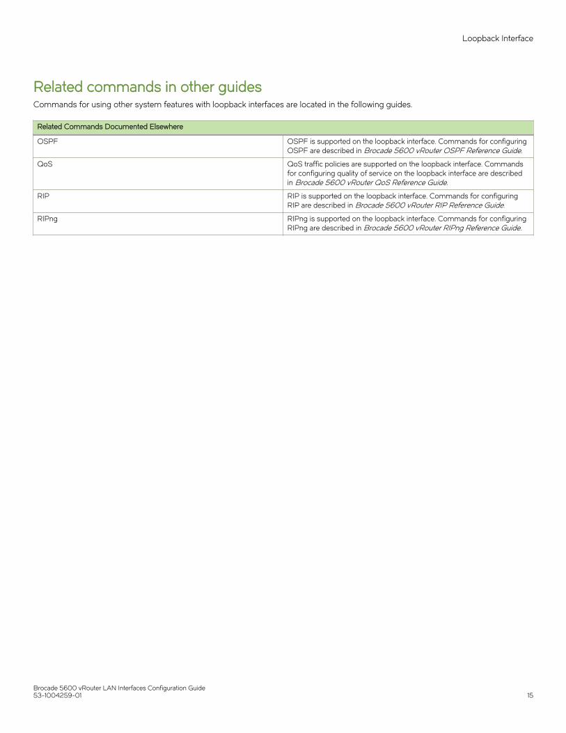
Related commands in other guidesCommands for using other system features with loopback interfaces are located in the following guides.
Related Commands Documented Elsewhere
OSPF OSPF is supported on the loopback interface. Commands for configuringOSPF are described in Brocade 5600 vRouter OSPF Reference Guide.
QoS QoS traffic policies are supported on the loopback interface. Commandsfor configuring quality of service on the loopback interface are describedin Brocade 5600 vRouter QoS Reference Guide.
RIP RIP is supported on the loopback interface. Commands for configuringRIP are described in Brocade 5600 vRouter RIP Reference Guide.
RIPng RIPng is supported on the loopback interface. Commands for configuringRIPng are described in Brocade 5600 vRouter RIPng Reference Guide.
Loopback Interface
Brocade 5600 vRouter LAN Interfaces Configuration Guide53-1004259-01 15

Loopback Interface
Brocade 5600 vRouter LAN Interfaces Configuration Guide16 53-1004259-01
Loopback Interface Commands∙ clear interfaces loopback counters........................................................................................................................................................................... 18∙ interfaces loopback <interface-name>.................................................................................................................................................................... 19∙ interfaces loopback <interface-name> address...............................................................................................................................................20∙ interfaces loopback <interface-name> description <description>............................................................................................................21∙ interfaces loopback <interface-name> ipv6 address....................................................................................................................................22∙ interfaces loopback <interface-name> ipv6 disable-forwarding............................................................................................................24∙ interfaces loopback <interface-name> ipv6 dup-addr-detect-transmits..........................................................................................25∙ interfaces loopback <interface-name> ipv6 router-advert........................................................................................................................ 26∙ show interfaces loopback.............................................................................................................................................................................................30
Brocade 5600 vRouter LAN Interfaces Configuration Guide53-1004259-01 17
clear interfaces loopback countersClears statistics counters for loopback interfaces.
Syntaxclear interfaces loopback [ interface-name ] counters
Command DefaultThe statistics counters for all loopback interfaces are cleared.
Parametersinterface-name
Clears statistics counters for a loopback interface, lo or lon, where n ranges from 1 through 99999. If an interface is notspecified, this command clears the counters of all loopback interfaces.
ModesOperational mode
Usage GuidelinesUse this command to clear statistics counters for loopback interfaces.
Loopback Interface Commands
Brocade 5600 vRouter LAN Interfaces Configuration Guide18 53-1004259-01
interfaces loopback <interface-name>Defines a loopback interface.
Syntaxset interfaces loopback interface-name
delete interfaces loopback [ interface-name ]
show interfaces loopback
Command DefaultA configuration node is automatically created for the lo loopback interface on startup.
Parametersinterface-name
The name of a loopback interface, lo or lon, where n ranges from 1 through 99999.
ModesConfiguration mode
Configuration Statementinterfaces { loopback interface-name}
Usage GuidelinesUse this command to configure a loopback interface.
Use the set form of this command to create a loopback interface. However, the system automatically creates a configurationnode for the lo loopback interface on startup, so you should not need to use the set form of this command to create the loloopback interface unless you have deleted it.
Use the delete form of this command to remove all loopback interfaces or just one. The system creates an empty configurationnode for the lo interface the next time the system starts.
Use the show form of this command to display the configured loopback interfaces.
Loopback Interface Commands
Brocade 5600 vRouter LAN Interfaces Configuration Guide53-1004259-01 19
interfaces loopback <interface-name> addressSpecifies the IP address and network prefix for a loopback interface.
Syntaxset interfaces loopback interface-name address { ipv4 | ipv6 }
delete interfaces loopback interface-name address { ipv4 | ipv6 }
show interfaces loopback interface-name address
Parametersinterface-name
The name of a loopback interface, lo or lon, where n ranges from 1 through 99999.
ipv4The IPv4 address and network prefix of the loopback interface. The format is ip-address / prefix (for example,127.0.0.1/8).You can define multiple IP addresses for the loopback interface by creating multiple address configuration nodes.
ipv6The IPv6 address and network prefix of the loopback interface. The format is ipv6-address / prefix (for example, ::1/128).You can define multiple IPv6 addresses for the loopback interface, by creating multiple address configuration nodes.
ModesConfiguration mode
Configuration Statementinterfaces { loopback interface-name { address ipv4 address ipv6 }}
Usage GuidelinesUse the set form of this command to specify the IP address and network prefix for a loopback interface. You can specify morethan one IP address and network prefix for a loopback interface by creating multiple address configuration nodes.
Use the delete form of this command to delete an address and network prefix for a loopback interface.
Use the show form of this command to display the address configuration of a loopback interface.
Loopback Interface Commands
Brocade 5600 vRouter LAN Interfaces Configuration Guide20 53-1004259-01
interfaces loopback <interface-name> description <description>Describes a loopback interface.
Syntaxset interfaces loopback interface-name description description
delete interfaces loopback interface-name description
show interfaces loopback interface-name description
Parametersinterface-name
The name of a loopback interface, lo or lon, where n ranges from 1 through 99999.
descriptionA description for the loopback interface.
ModesConfiguration mode
Configuration Statementinterfaces { loopback interface-name { description description }}
Usage GuidelinesUse this command to describe a loopback interface.
Use the set form of this command to describe a loopback interface.
Use the delete form of this command to delete the description of a loopback interface.
Use the show form of this command to display the description of a loopback interface.
Loopback Interface Commands
Brocade 5600 vRouter LAN Interfaces Configuration Guide53-1004259-01 21
interfaces loopback <interface-name> ipv6 addressSpecifies a method for assigning an IPv6 address to a loopback interface.
Syntaxset interfaces loopback interface-name ipv6 address { autoconf | eui64 ipv6prefix }
delete interfaces loopback interface-name ipv6 address { autoconf | eui64 ipv6prefix }
show interfaces loopback interface-name ipv6 address { autoconf | eui64 }
Parametersinterface-name
The name of a loopback interface, lo or lon, where n ranges from 1 through 99999.
autoconfGenerates an IPv6 address by using the SLAAC protocol. Use this keyword if the interface is performing a “host”function rather than a “router” function. You can specify this keyword in addition to static IPv6, static IPv4, and IPv4DHCP addresses on the interface.
eui64 ipv6prefixSpecifies the 64-bit IPv6 address prefix that is used to configure an IPv6 address in EUI-64 format. The systemconcatenates this prefix with a 64-bit EUI-64 value that is derived from the 48-bit MAC address of the interface.
ModesConfiguration mode
Configuration Statementinterfaces { loopback interface-name { ipv6 { address { autoconf eui64 ipv6prefix } } }}
Usage GuidelinesUse this command to specify a method for assigning an IPv6 address to a loopback interface.
Use the autoconf keyword to direct the system to automatically configure (autoconfigure) the address by using the StatelessAddress Autoconfiguration (SLAAC) protocol that is defined in RFC 4862. Alternatively, you can provide an EUI-64 IPv6address prefix so that the system constructs the IPv6 address.
If you want the system to use SLAAC to acquire an address on the interface, then in addition to setting this parameter, youmust also disable IPv6 forwarding, either globally (by using the system ipv6 disable-forwarding command) or specifically on theinterface (by using the interfaces ethernet ethx ipv6 disable-forwarding command).
Use the set form of this command to specify a method for assigning an IPv6 address to a loopback interface.
Loopback Interface Commands
Brocade 5600 vRouter LAN Interfaces Configuration Guide22 53-1004259-01

Use the delete form of this command to delete an IPv6 address from a loopback interface.
Use the show form of this command to display IPv6 address configuration settings for a loopback interface.
Loopback Interface Commands
Brocade 5600 vRouter LAN Interfaces Configuration Guide53-1004259-01 23
interfaces loopback <interface-name> ipv6 disable-forwardingDisables IPv6 packet forwarding on the loopback interface.
Syntaxset interfaces loopback interface-name ipv6 disable-forwarding
delete interfaces loopback interface-name ipv6 disable-forwarding
show interfaces loopback interface-name ipv6 disable-forwarding
Command DefaultIPv6 packets are forwarded.
Parametersinterface-name
The name of a loopback interface, lo or lon, where n ranges from 1 through 99999.
ModesConfiguration mode
Configuration Statementinterfaces { loopback interface-name { ipv6 { disable-forwarding } }}
Usage GuidelinesUse this command to disable IPv6 packet forwarding on a loopback interface.
You can also disable IPv6 forwarding globally (that is, for all interfaces) by using the system ipv6 disable-forwarding command.
Use the set form of this command to disable IPv6 packet forwarding on a loopback interface.
Use the delete form of this command to enable IPv6 packet forwarding on a loopback interface.
Use the show form of this command to display the configuration of IPv6 packet forwarding on a loopback interface.
Loopback Interface Commands
Brocade 5600 vRouter LAN Interfaces Configuration Guide24 53-1004259-01
interfaces loopback <interface-name> ipv6 dup-addr-detect-transmitsSpecifies the number of NS packets to transmit as part of the DAD process.
Syntaxset interfaces loopback interface-name ipv6 dup-addr-detect-transmits [ 0 | number ]
delete interfaces loopback interface-name ipv6 dup-addr-detect-transmits
show interfaces loopback interface-name ipv6 dup-addr-detect-transmits
Command DefaultOne NS packet is transmitted as part of the DAD process.
Parametersinterface-name
The name of a loopback interface, lo or lon, where n ranges from 1 through 99999.
0Disables DAD on the loopback interface.
numberThe number of NS packets to transmit as part of the DAD process. The number ranges from 1 through n. The defaultnumber is 1.
ModesConfiguration mode
Configuration Statementinterfaces { loopback interface-name { ipv6 { dup-addr-detect-transmits 0 dup-addr-detect-transmits number } }}
Usage GuidelinesUse this command to specify the number of Neighbor Solicitation (NS) packets to transmit as part of the Duplicate AddressDetection (DAD) process.
Use the set form of this command to specify the number of NS packets to transmit.
Use the delete form of this command to delete the transmission number from a loopback interface and transmit the defaultnumber of one NS packet.
Use the show form of this command to display the number of NS packets that are transmitted.
Loopback Interface Commands
Brocade 5600 vRouter LAN Interfaces Configuration Guide53-1004259-01 25
interfaces loopback <interface-name> ipv6 router-advertSpecifies the router advertisements to be sent from a loopback interface.
Syntaxset interfaces loopback interface-name ipv6 router-advert [ cur-hop-limit limit ] [ default-lifetime lifetime ] [ default-preference
preference ] [ link-mtu mtu ] [ managed-flag state ] [ max-interval interval ] [ min-interval interval ] [ other-config-flag state ][ prefix ipv6net [ autonomous-flag state | on-link-flag state | preferred-lifetime lifetime | valid-lifetime lifetime ] ][ reachable-time time ] [ retrans-timer time ] [ send-advert state ]
delete interfaces loopback interface-name ipv6 router-advert [ cur-hop-limit ] [ default-lifetime ] [ default-preference ] [ link-mtu ] [ managed-flag ] [ max-interval ] [ min-interval ] [ other-config-flag ] [ prefix ipv6net [ autonomous-flag | on-link-flag |preferred-lifetime | valid-lifetime ] ] [ reachable-time ] [ retrans-timer] [ send-advert ]
show interfaces loopback interface-name ipv6 router-advert
Command DefaultRouter advertisements are not sent on an interface.
Parametersinterface-name
The name of a loopback interface, lo or lon, where n ranges from 1 through 99999.
cur-hop-limit limitSpecifies the hop-count limit of the IP header for outgoing (unicast) IP packets. This limit is placed in the Hop Countfield of the IP header for outgoing (unicast) IP packets. The limit ranges from 0 through 255. The default limit is 64. Alimit of 0 means unspecified by the router.
default-lifetime lifetimeSpecifies the lifetime, in seconds, that is associated with the default router. A lifetime of 0 indicates that the router isnot a default router. The lifetime ranges from the value that is configured for the max-interval option to 9000 (18.2hours). If the lifetime is not configured, the value for this timer is three times max-interval.
default-preference preferenceSpecifies the preference that is associated with the default router. The preference is low, medium, or high.The default preference is medium.
link-mtu mtuSpecifies the MTU to be advertised for the link. The MTU is 0 or ranges from 1280 through the maximum MTU forthe type of link, as defined in RFC 2464. The default MTU is 0, which means the MTU is not specified in the routeradvertisement message. That is because it is expected that the MTU is configured directly on the interface itself andnot for routing advertisements. You can configure this option when the link MTU is not well known.If the MTU that is set here does not match the MTU that is configured on the interface, the system issues a warningbut does not fail.
managed-flag stateSpecifies whether to use the administered protocol for address autoconfiguration. The state is either of the following:true: Hosts use the administered (stateful) protocol for address autoconfiguration in addition to any addressesautoconfigured by using stateless address autoconfiguration.false: Hosts use only stateless address autoconfiguration.
Loopback Interface Commands
Brocade 5600 vRouter LAN Interfaces Configuration Guide26 53-1004259-01
The default state is false.
max-interval intervalSpecifies the maximum time, in seconds, that is allowed between sending unsolicited multicast router advertisementsfrom the interface. The interval ranges from 4 through 1800. The default is 600 (10 minutes).
min-interval intervalSpecifies the minimum time, in seconds, that is allowed between sending unsolicited multicast router advertisementsfrom the interface. The interval ranges from 3 through 0.75 times the max-interval option. The default interval is 0.33times max-interval.
other-config-flag stateSpecifies that the interface use the administered (stateful) protocol for autoconfiguration of nonaddress information, asdefined in RFC 4862. The state is either of the following:true: Hosts use the administered protocol for autoconfiguration of nonaddress information.false: Hosts use stateless autoconfiguration of nonaddress information.The default state is false.
prefix ipv6netMultinode. Specifies the IPv6 prefix to be advertised on the IPv6 interface, in the format ipv6-address / prefix.You can define more than one IPv6 prefix by configuring multiple prefix configuration nodes.
autonomous-flag stateSpecifies whether the prefix can be used for autonomous address configuration, as defined in RFC 4862. The state iseither of the following:true: The prefix can be used for autonomous address configuration.false: The prefix cannot be used for autonomous address configuration.The default state is true.
on-link-flag stateSpecifies whether the prefix can be used for onlink determination, as defined in RFC 4862. The state is either of thefollowing:true: The prefix can be used for onlink determination.false: The advertisement makes no statement about onlink or off-link properties of the prefix. For instance, the prefixmight be used for address configuration with some addresses belonging to the prefix being onlink and others beingoff-link.The default state is true.
preferred-lifetime lifetimeSpecifies the length of time, in seconds, that the addresses generated from the prefix by Stateless AddressAutoconfiguration (SLAAC) is to remain preferred, as defined in RFC 4862. The interval is with respect to the time thepacket is sent. The lifetime ranges from 1 through 4294967296 plus the infinity keyword, which represents forever.(The actual value of infinity is a byte in which all bits are set to 1s: 0XFFFFFFFF.) The default lifetime is 604800 (7days).
valid-lifetime lifetimeSpecifies the length of time, in seconds, that the prefix is valid for onlink determination, as defined in RFC 4862. Theinterval is with respect to the time the packet is sent. The lifetime ranges from 1 through 4294967296 plus the infinitykeyword, which represents forever. (The actual value of infinity is a byte in which all bits are set to 1s: 0XFFFFFFFF.)The default lifetime is 2592000 (30 days).
reachable-time timeSpecifies the length of time, in milliseconds, for which the system assumes a neighbor is reachable after havingreceived a reachability confirmation. This time is used by address resolution and the Neighbor Unreachability
Loopback Interface Commands
Brocade 5600 vRouter LAN Interfaces Configuration Guide53-1004259-01 27
Detection algorithm (see Section 7.3 of RFC 2461). The time ranges from 0 through 3600000, where a value of 0means the reachable time is not specified in the router advertisement message. The default time is 0.
retrans-timer timeSpecifies the length of time, in milliseconds, between retransmitted NS messages. This time is used by addressresolution and the Neighbor Unreachability Detection algorithm (see Sections 7.2 and 7.3 of RFC 2461). The timeranges from 0 through 4294967295, where a value of 0 means the retransmit time is not specified in the routeradvertisement message. The default time is 0.
send-advert stateSpecifies whether router advertisements are to be sent from this interface. The state is either of the following:true: Sends router advertisements from this interface.false: Does not send router advertisements from this interface. If a state is in effect, parameters in this configurationsubtree are still used to configure the local implementation parameters.The default state is true.
ModesConfiguration mode
Configuration Statementinterfaces { loopback interface-name { ipv6 { router-advert { cur-hop-limit limit default-lifetime lifetime default-preference preference link-mtu mtu managed-flag state max-interval interval min-interval interval other-config-flag state prefix ipv6net { autonomous-flag state on-link-flag state preferred-lifetime lifetime valid-lifetime lifetime reachable-time time retrans-timer time send-advert state } } } }}
Usage GuidelinesUse this command to configure router advertisements (RAs) to be sent from the loopback interface being configured.
Router advertisements are sent by IPv6 routers to advertise their existence to hosts on the network. IPv6 hosts do not sendrouter advertisements.
If the router-advert node of the configuration tree is missing, router advertisements are not sent. In addition, if IPv6 forwardingis disabled either globally (by using the system ipv6 disable-forwarding command) or on the interface, router advertisementsare not sent.
Loopback Interface Commands
Brocade 5600 vRouter LAN Interfaces Configuration Guide28 53-1004259-01

Most parameters for router advertisements are required by either the Neighbor Discovery (ND) protocol or the StatelessAddress Autoconfiguration (SLAAC) protocol. These parameters are used both locally for the IPv6 implementation andbecome part of the RA messages sent to hosts on the network so that they can be configured appropriately.
Use the set form of this command to create the router-advert configuration node and begin to send router advertisements.
Use the delete form of this command to delete the router-advert configuration node and stop sending router advertisements.
Use the show form of this command to display the configuration of router advertisements.
Loopback Interface Commands
Brocade 5600 vRouter LAN Interfaces Configuration Guide53-1004259-01 29
show interfaces loopbackDisplays statistics and configuration information about configured loopback interfaces.
Syntaxshow interfaces loopback [ interface-name [ brief ] | detail ]
Command DefaultWhen used with no option, this command displays a brief status of the loopback interface.
Parametersinterface-name
The name of a loopback interface, lo or lon, where n ranges from 1 through 99999.
briefDisplays a brief status of a loopback interface.
detailDisplays detailed information and statistics about all loopback interfaces.
ModesOperational mode
Usage GuidelinesUse this command to display information about loopback interfaces.
Loopback Interface Commands
Brocade 5600 vRouter LAN Interfaces Configuration Guide30 53-1004259-01
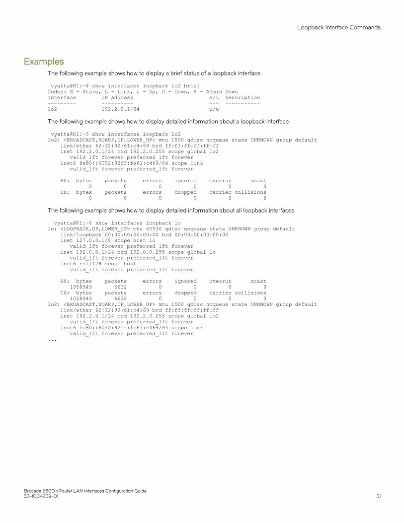
ExamplesThe following example shows how to display a brief status of a loopback interface.
vyatta@R1:~$ show interfaces loopback lo2 briefCodes: S - State, L - Link, u - Up, D - Down, A - Admin DownInterface IP Address S/L Description--------- ---------- --- -----------lo2 192.2.0.1/24 u/u
The following example shows how to display detailed information about a loopback interface.
vyatta@R1:~$ show interfaces loopback lo2lo2: <BROADCAST,NOARP,UP,LOWER_UP> mtu 1500 qdisc noqueue state UNKNOWN group default link/ether 62:32:92:61:c4:69 brd ff:ff:ff:ff:ff:ff inet 192.2.0.1/24 brd 192.2.0.255 scope global lo2 valid_lft forever preferred_lft forever inet6 fe80::6032:92ff:fe61:c469/64 scope link valid_lft forever preferred_lft forever
RX: bytes packets errors ignored overrun mcast 0 0 0 0 0 0 TX: bytes packets errors dropped carrier collisions 0 0 0 0 0 0
The following example shows how to display detailed information about all loopback interfaces.
vyatta@R1:~$ show interfaces loopback lolo: <LOOPBACK,UP,LOWER_UP> mtu 65536 qdisc noqueue state UNKNOWN group default link/loopback 00:00:00:00:00:00 brd 00:00:00:00:00:00 inet 127.0.0.1/8 scope host lo valid_lft forever preferred_lft forever inet 192.0.0.1/24 brd 192.0.0.255 scope global lo valid_lft forever preferred_lft forever inet6 ::1/128 scope host valid_lft forever preferred_lft forever
RX: bytes packets errors ignored overrun mcast 1058949 6632 0 0 0 0 TX: bytes packets errors dropped carrier collisions 1058949 6632 0 0 0 0lo2: <BROADCAST,NOARP,UP,LOWER_UP> mtu 1500 qdisc noqueue state UNKNOWN group default link/ether 62:32:92:61:c4:69 brd ff:ff:ff:ff:ff:ff inet 192.2.0.1/24 brd 192.2.0.255 scope global lo2 valid_lft forever preferred_lft forever inet6 fe80::6032:92ff:fe61:c469/64 scope link valid_lft forever preferred_lft forever...
Loopback Interface Commands
Brocade 5600 vRouter LAN Interfaces Configuration Guide53-1004259-01 31

Loopback Interface Commands
Brocade 5600 vRouter LAN Interfaces Configuration Guide32 53-1004259-01
Data Plane Interfaces∙ Data plane interfaces overview..................................................................................................................................................................................33∙ Examples of data plane interface configuration...............................................................................................................................................33
Data plane interfaces overviewA system receives packets from neighboring systems through its network interfaces. On the LAN, an interface is typically an Ethernetinterface. In the Brocade vRouter, a data plane interface is an abstraction that represents the underlying physical or virtual Ethernetinterface of the system.
NOTEThe terms Ethernet interface and data plane interface are synonymous in this guide.
Ethernet interfaces are viewed and configured in the interfaces ethernet node of the configuration tree. The system automaticallydiscovers the physical interfaces on the system and creates entries for them in the configuration tree on startup. For example, on asystem with two Ethernet interfaces, the router automatically creates configuration nodes for dp0p1p1 and dp0p1p2.
After the interface is enabled and provided with an address, you can configure it with various system features, such as firewall, routingprotocols, quality of service, and so on.
The Brocade vRouter has extensive support for IPv6, including IPv6 interface addressing. The commands for configuring IPv6 onEthernet interfaces are given in this chapter. Brocade 5600 vRouter IPv6 Support Reference Guide fully describes Brocade vRouterIPv6 support.
Examples of data plane interface configurationThis section presents the following topics:
∙ Viewing system interfaces on page 33
∙ Basic configuration of a data plane interface on page 34
∙ Ethernet multinetting on page 35
∙ Examples of data plane interface configuration
Viewing system interfacesYou can configure only interfaces that are physically available to the operating system on the hardware you are using. To view all theinterfaces known to the operating system, use the show interfaces system command in operational mode, as shown in the followingexample. In this example, the system has two physical Ethernet interfaces, dp0p1p1 and dp0p1p2, plus a VLAN interface (vif) configuredfor VLAN 40 that is under dp0p1p2.
Viewing available system interfacesvyatta@vyatta:~$ show interfaces system
1: lo: <LOOPBACK,UP,LOWER_UP> mtu 65536 qdisc noqueue state UNKNOWN mode DEFAULT group default link/loopback 00:00:00:00:00:00 brd 00:00:00:00:00:00 promiscuity 0 RX: bytes packets errors dropped overrun mcast 20843877 133515 0 0 0 0 TX: bytes packets errors dropped carrier collsns 20843877 133515 0 0 0 0
Brocade 5600 vRouter LAN Interfaces Configuration Guide53-1004259-01 33
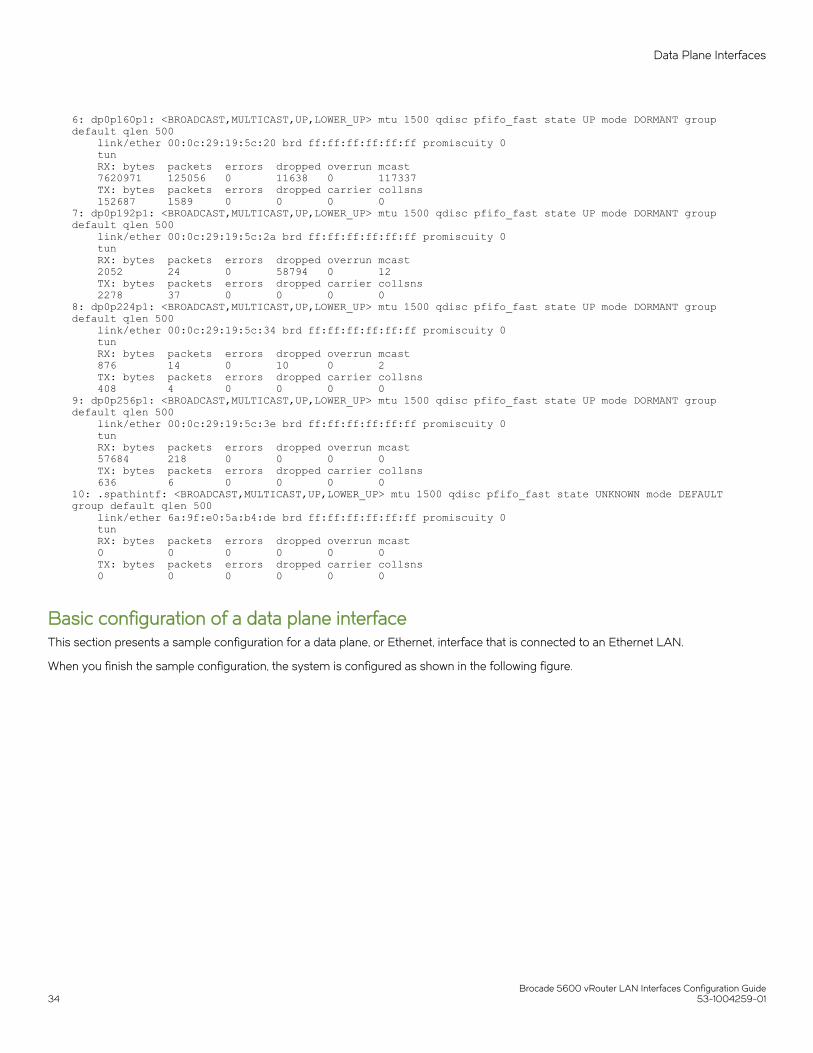
6: dp0p160p1: <BROADCAST,MULTICAST,UP,LOWER_UP> mtu 1500 qdisc pfifo_fast state UP mode DORMANT group default qlen 500 link/ether 00:0c:29:19:5c:20 brd ff:ff:ff:ff:ff:ff promiscuity 0 tun RX: bytes packets errors dropped overrun mcast 7620971 125056 0 11638 0 117337 TX: bytes packets errors dropped carrier collsns 152687 1589 0 0 0 07: dp0p192p1: <BROADCAST,MULTICAST,UP,LOWER_UP> mtu 1500 qdisc pfifo_fast state UP mode DORMANT group default qlen 500 link/ether 00:0c:29:19:5c:2a brd ff:ff:ff:ff:ff:ff promiscuity 0 tun RX: bytes packets errors dropped overrun mcast 2052 24 0 58794 0 12 TX: bytes packets errors dropped carrier collsns 2278 37 0 0 0 08: dp0p224p1: <BROADCAST,MULTICAST,UP,LOWER_UP> mtu 1500 qdisc pfifo_fast state UP mode DORMANT group default qlen 500 link/ether 00:0c:29:19:5c:34 brd ff:ff:ff:ff:ff:ff promiscuity 0 tun RX: bytes packets errors dropped overrun mcast 876 14 0 10 0 2 TX: bytes packets errors dropped carrier collsns 408 4 0 0 0 09: dp0p256p1: <BROADCAST,MULTICAST,UP,LOWER_UP> mtu 1500 qdisc pfifo_fast state UP mode DORMANT group default qlen 500 link/ether 00:0c:29:19:5c:3e brd ff:ff:ff:ff:ff:ff promiscuity 0 tun RX: bytes packets errors dropped overrun mcast 57684 218 0 0 0 0 TX: bytes packets errors dropped carrier collsns 636 6 0 0 0 010: .spathintf: <BROADCAST,MULTICAST,UP,LOWER_UP> mtu 1500 qdisc pfifo_fast state UNKNOWN mode DEFAULT group default qlen 500 link/ether 6a:9f:e0:5a:b4:de brd ff:ff:ff:ff:ff:ff promiscuity 0 tun RX: bytes packets errors dropped overrun mcast 0 0 0 0 0 0 TX: bytes packets errors dropped carrier collsns 0 0 0 0 0 0
Basic configuration of a data plane interfaceThis section presents a sample configuration for a data plane, or Ethernet, interface that is connected to an Ethernet LAN.
When you finish the sample configuration, the system is configured as shown in the following figure.
Data Plane Interfaces
Brocade 5600 vRouter LAN Interfaces Configuration Guide34 53-1004259-01
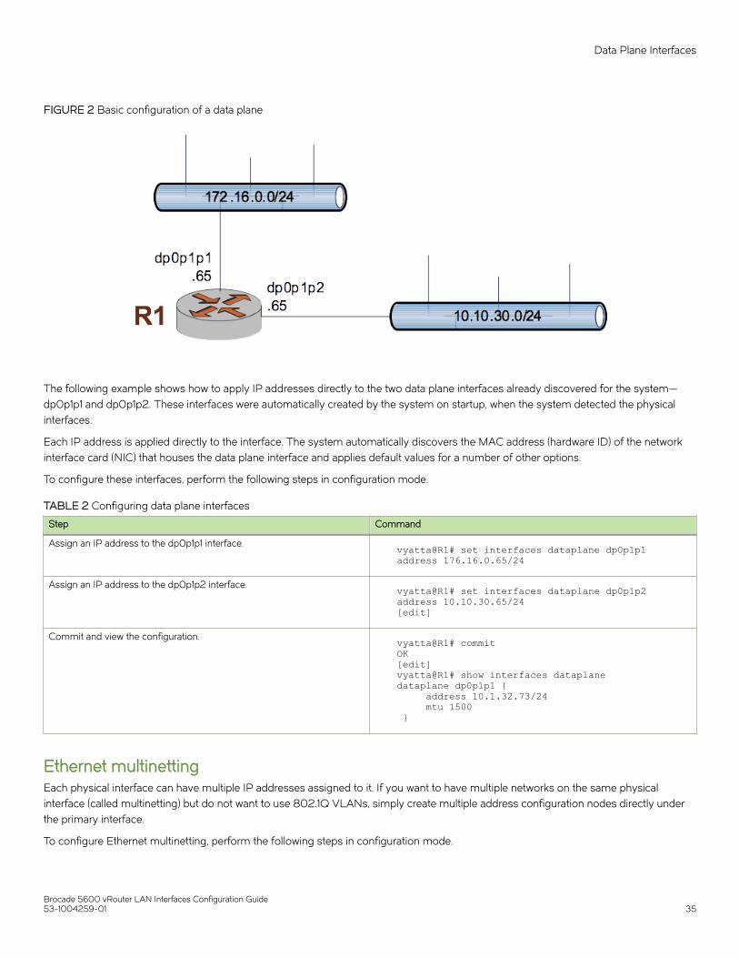
FIGURE 2 Basic configuration of a data plane
The following example shows how to apply IP addresses directly to the two data plane interfaces already discovered for the system—dp0p1p1 and dp0p1p2. These interfaces were automatically created by the system on startup, when the system detected the physicalinterfaces.
Each IP address is applied directly to the interface. The system automatically discovers the MAC address (hardware ID) of the networkinterface card (NIC) that houses the data plane interface and applies default values for a number of other options.
To configure these interfaces, perform the following steps in configuration mode.
TABLE 2 Configuring data plane interfaces
Step Command
Assign an IP address to the dp0p1p1 interface. vyatta@R1# set interfaces dataplane dp0p1p1 address 176.16.0.65/24
Assign an IP address to the dp0p1p2 interface. vyatta@R1# set interfaces dataplane dp0p1p2 address 10.10.30.65/24 [edit]
Commit and view the configuration. vyatta@R1# commitOK[edit]vyatta@R1# show interfaces dataplanedataplane dp0p1p1 { address 10.1.32.73/24 mtu 1500 }
Ethernet multinettingEach physical interface can have multiple IP addresses assigned to it. If you want to have multiple networks on the same physicalinterface (called multinetting) but do not want to use 802.1Q VLANs, simply create multiple address configuration nodes directly underthe primary interface.
To configure Ethernet multinetting, perform the following steps in configuration mode.
Data Plane Interfaces
Brocade 5600 vRouter LAN Interfaces Configuration Guide53-1004259-01 35
TABLE 3 Configuring Ethernet multinetting
Step Command
Assign the first IP address to the dp0p1p1interface.
vyatta@R2# set interfaces dataplane dp0p1p1 address 172.16.0.65/24
Assign the second IP address to the dp0p1p1interface.
vyatta@R1# set interfaces dataplane dp0p1p1 address 192.168.1.17/24
Commit and view the configuration. vyatta@R1# commitOK[edit]
vyatta@R1# show interfaces dataplane dp0p1p1 address 192.168.1.81/24 address 192.168.1.17/24
IPv6 on data plane interfacesBrocade 5600 vRouter IPv6 Support Reference Guide provides examples of configuring IPv6 on interfaces.
Hardware binding for data plane interfacesThe vRouter provides you with the option to override the names of vRouter data plane interfaces to ensure that these names remainbound to network interface cards (NICs), which is useful in the following scenarios.
∙ Moving a NIC from a damaged slot to a different slot (slot-number- or PCI-address-based binding)
∙ Moving a NIC from one slot to another (MAC-address based binding)
∙ Naming data plane interfaces the same across different chassis, hypervisors, and cloud environments
The hardware-binding commands have the following syntax:
interfaces dataplane interface-name hardware binding-keyword-and-value
For information about hardware-binding commands, refer to Data Plane Interfaces Commands on page 39.
Command dependenciesSome of the hardware-binding commands must be run with other hardware-binding commands; otherwise, commit fails.
The following examples show the commands that you can run individually and those that you must run with other commands.
∙ The following command binds dp0s5 to the NIC at the 0:00:05.0 PCI address.
set interfaces dataplane dp0s5 hardware pci-address 0:00:05.0
∙ The following command binds dp0s7 to port 0 on a system that has a single NIC.
set interfaces dataplane dp0s7 hardware port 0
∙ The following command binds dp0s9 to the NIC whose MAC address is b0:03:f4:02:02:05.
set interfaces dataplane dp0s9 hardware mac b0:03:f4:02:02:05
∙ The following command binds dp0s10 to the onboard NIC whose firmware index is 39.
set interfaces dataplane dp0s10 hardware firmware-index 39
∙ The following commands bind dp0s6 to function 0 of the NIC in PCI slot 6.
set interfaces dataplane dp0s6 hardware pci-slot 6
Data Plane Interfaces
Brocade 5600 vRouter LAN Interfaces Configuration Guide36 53-1004259-01
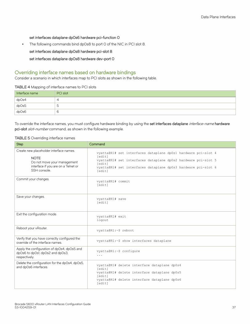
set interfaces dataplane dp0s6 hardware pci-function 0
∙ The following commands bind dp0s8 to port 0 of the NIC in PCI slot 8.
set interfaces dataplane dp0s8 hardware pci-slot 8
set interfaces dataplane dp0s8 hardware dev-port 0
Overriding interface names based on hardware bindingsConsider a scenario in which interfaces map to PCI slots as shown in the following table.
TABLE 4 Mapping of interface names to PCI slots
Interface name PCI slot
dp0s4 4
dp0s5 5
dp0s6 6
To override the interface names, you must configure hardware binding by using the set interfaces dataplane interface-name hardwarepci-slot slot-number command, as shown in the following example.
TABLE 5 Overriding interface names
Step Command
Create new placeholder interface names.
NOTEDo not move your managementinterface if you are on a Telnet orSSH console.
vyatta@R1# set interfaces dataplane dp0s1 hardware pci-slot 4[edit]vyatta@R1# set interfaces dataplane dp0s2 hardware pci-slot 5[edit]vyatta@R1# set interfaces dataplane dp0s3 hardware pci-slot 6[edit]
Commit your changes. vyatta@R1# commit[edit]
Save your changes. vyatta@R1# save[edit]
Exit the configuration mode. vyatta@R1# exitlogout
Reboot your vRouter. vyatta@R1:~$ reboot
Verify that you have correctly configured theoverride of the interface names.
vyatta@R1:~$ show interfaces dataplane
Apply the configuration of dp0s4, dp0s5 anddp0s6 to dp0s1, dp0s2 and dp0s3,respectively.
vyatta@R1:~$ configure...
Delete the configuration for the dp0s4, dp0s5,and dp0s6 interfaces.
vyatta@R1# delete interface dataplane dp0s4[edit]vyatta@R1# delete interface dataplane dp0s5[edit]vyatta@R1# delete interface dataplane dp0s6[edit]
Data Plane Interfaces
Brocade 5600 vRouter LAN Interfaces Configuration Guide53-1004259-01 37
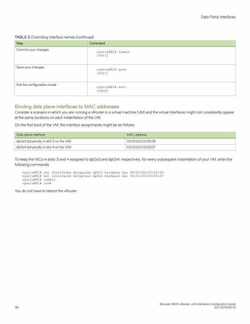
TABLE 5 Overriding interface names (continued)
Step Command
Commit your changes. vyatta@R1# commit[edit]
Save your changes. vyatta@R1# save[edit]
Exit the configuration mode. vyatta@R1# exitlogout
Binding data plane interfaces to MAC addressesConsider a scenario in which you are running a vRouter in a virtual machine (VM) and the virtual interfaces might not consistently appearat the same locations on each instantiation of the VM.
On the first boot of the VM, the interface assignments might be as follows:
Data plane interface MAC address
dp0s3 (physically in slot 3 on the VM) 00:01:02:03:05:06
dp0s4 (physically in slot 4 on the VM) 00:01:02:03:05:07
To keep the NICs in slots 3 and 4 assigned to dp0s3 and dp0s4, respectively, for every subsequent instantiation of your VM, enter thefollowing commands:
vyatta@R1# set interfaces dataplane dp0s3 hardware mac 00:01:02:03:05:06 vyatta@R1# set interfaces dataplane dp0s4 hardware mac 00:01:02:03:05:07 vyatta@R1# commitvyatta@R1# save
You do not have to reboot the vRouter.
Data Plane Interfaces
Brocade 5600 vRouter LAN Interfaces Configuration Guide38 53-1004259-01
Data Plane Interfaces Commands∙ clear interfaces dataplane counters........................................................................................................................................................................ 40∙ interfaces dataplane <interface-name>...................................................................................................................................................................41∙ interfaces dataplane <interface-name> address..............................................................................................................................................42∙ interfaces dataplane <interface-name> bond-group <bondx>.................................................................................................................43∙ interfaces dataplane <interface-name> description <description>.........................................................................................................44∙ interfaces dataplane <interface-name> dhcp-options no-rfc3442......................................................................................................45∙ interfaces dataplane <interface-name> dhcpv6-options............................................................................................................................ 47∙ interfaces dataplane <interface-name> disable................................................................................................................................................48∙ interfaces dataplane <interface-name> disable-link-detect......................................................................................................................49∙ interfaces dataplane <interface-name> hardware dev-port <port-number>................................................................................... 50∙ interfaces dataplane <interface-name> hardware firmware-index <firmware-index>.................................................................. 51∙ interfaces dataplane <interface-name> hardware mac <mac-address>............................................................................................ 52∙ interfaces dataplane <interface-name> hardware pci-address <pci-address>...............................................................................53∙ interfaces dataplane <interface-name> hardware pci-function <function-number>...................................................................55∙ interfaces dataplane <interface-name> hardware pci-slot <slot-number>....................................................................................... 56∙ interfaces dataplane <interface-name> hardware port <port-number>...............................................................................................57∙ interfaces dataplane <interface-name> ip disable-forwarding................................................................................................................ 58∙ interfaces dataplane <interface-name> ip enable-proxy-arp................................................................................................................... 59∙ interfaces dataplane <interface-name> ip pim mode <mode>................................................................................................................60∙ interfaces dataplane <interface-name> ip rpf-check.......................................................................................................................................61∙ interfaces dataplane <interface-name> ipv6 address...................................................................................................................................62∙ interfaces dataplane <interface-name> ipv6 disable-forwarding...........................................................................................................64∙ interfaces dataplane <interface-name> ipv6 dup-addr-detect-transmits <num>........................................................................ 65∙ interfaces dataplane <interface-name> ipv6 router-advert.......................................................................................................................66∙ interfaces dataplane <interface-name> mac <mac-addr>..........................................................................................................................70∙ interfaces dataplane <interface-name> mtu <mtu>.......................................................................................................................................... 71∙ interfaces dataplane <interface-name> vif <vif-id> dhcp-options no-rfc3442..............................................................................72∙ interfaces dataplane <interface-name> vif <vif-id> policy qos <name>...............................................................................................74∙ interfaces dataplane <interface-name> vrrp vrrp-group <vrrp-group-id> notify bgp.................................................................75∙ monitor interfaces dataplane <interface-name> traffic................................................................................................................................. 77∙ show interfaces dataplane............................................................................................................................................................................................ 78∙ show interfaces dataplane detail............................................................................................................................................................................... 79∙ show interfaces dataplane <interface-name> brief.......................................................................................................................................... 81∙ show interfaces dataplane <interface-name> physical................................................................................................................................ 82∙ Related commands documented elsewhere.....................................................................................................................................................83
Brocade 5600 vRouter LAN Interfaces Configuration Guide53-1004259-01 39
clear interfaces dataplane countersClears statistics counters for a single data plane interface or all data plane interfaces.
Syntaxclear interfaces dataplane [ interface-name ] counters
Command DefaultStatistics counters for all data plane interfaces are cleared.
Parametersinterface-name
The identifier of a data plane interface. For more information about the supported interface name formats, refer to Data Plane Interface on page 215.
ModesOperational mode
Usage GuidelinesUse this command to clear statistics counters for a single data plane interface or all data plane interfaces.
Data Plane Interfaces Commands
Brocade 5600 vRouter LAN Interfaces Configuration Guide40 53-1004259-01
interfaces dataplane <interface-name>Defines a data plane interface.
Syntaxset interfaces dataplane interface-name
delete interfaces dataplane interface-name
show interfaces dataplane interface-name
Parametersinterface-name
The name of a data plane interface. For more information about the supported interface name formats, refer to DataPlane Interface on page 215.
ModesConfiguration mode
Configuration Statementinterfaces { dataplane interface-name}
Usage GuidelinesUse this command to create a data plane interface.
Use the set form of this command to create a data plane interface.
Use the delete form of this command to delete a data plane interface. The system creates an empty configuration node for theinterface the next time the system starts.
Use the show form of this command to display data plane interface configuration.
Data Plane Interfaces Commands
Brocade 5600 vRouter LAN Interfaces Configuration Guide53-1004259-01 41
interfaces dataplane <interface-name> addressSpecifies the IP address and network prefix for a data plane interface.
Syntaxset interfaces dataplane interface-name address { ipv4 | ipv6 | dhcp | dhcpv6 }
delete interfaces dataplane interface-name address [ ipv4 | ipv6 | dhcp | dhcpv6 ]
Parametersinterface-name
The name of a data plane interface. For more information about the supported interface name formats, refer to DataPlane Interface on page 215.
ipv4The IPv4 address of a data plane interface. The format is ip-address/prefix (for example, 192.168.1.77/24).
ipv6The IPv6 address of a data plane interface. The format is ipv6-address/prefix (for example, 2001:db8:1234::/48).
dhcpDefines the interface as a DHCP client, which obtains its address and prefix from a DHCP server.
dhcpv6Defines the interface as a DHCPv6 client, which obtains its address and prefix from a DHCPv6 server.
ModesConfiguration mode
Configuration Statementinterfaces { dataplane interface-name { address { ipv4 ipv6 dhcp dhcpv6 } }}
Usage GuidelinesUse this command to specify the IP address and network prefix for a data plane interface.
Use the set form of this command to set an IP address and a network prefix. You can set only one IP address for the interface.
Use the delete form of this command to delete an IP address and a network prefix.
Data Plane Interfaces Commands
Brocade 5600 vRouter LAN Interfaces Configuration Guide42 53-1004259-01
interfaces dataplane <interface-name> bond-group <bondx>Adds a data plane interface to a bonding group.
Syntaxset interfaces dataplane interface-name bond-group bondx
delete interfaces dataplane interface-name bond-group bondx
show interfaces dataplane interface-name bond-group bondx
Parametersinterface-name
The name of a data plane interface. For more information about the supported interface name formats, refer to DataPlane Interface on page 215.
bondxThe identifier for the bond group. Supported values are bond0 through bond99.
ModesConfiguration mode
Configuration Statementinterfaces { dataplane interface-name { bond-group bondx }}
Usage GuidelinesUse this command to add a data plane interface to a data plane link bond group.
A data plane interface can only be a member of one data plane link bond group and the bond group must first be defined using interfaces dataplane <interface-name> bond-group <bondx>. The maximum number of data plane interfaces that can be addedto a bonding group depends on available system resources. For most implementations this is essentially unlimited.
NOTEThe data plane interface will not be added to the bond group if it is disabled.
You must not configure any IP address for the data plane interface if it is to become part of a bonding group. Instead, the IPaddress for the group is configured on the bonding interface using interfaces dataplane <interface-name> address on page 42.
Use the set form of this command to add a data plane interface to a data plane link bond group.
Use the delete form of this command to remove a data plane interface from a data plane link bond group.
Use the show form of this command to view bond group configuration.
Data Plane Interfaces Commands
Brocade 5600 vRouter LAN Interfaces Configuration Guide53-1004259-01 43
interfaces dataplane <interface-name> description <description>Describes a data plane interface.
Syntaxset interfaces dataplane interface-name description description
delete interfaces dataplane interface-name description
show interfaces dataplane interface-name description
Parametersinterface-name
The name of a data plane interface. For more information about the supported interface name formats, refer to DataPlane Interface on page 215.
descriptionA mnemonic name or description for the data plane interface.
ModesConfiguration mode
Configuration Statementinterfaces { dataplane interface-name { description description }}
Usage GuidelinesUse this command to describe a data plane interface.
Use the set form of this command to describe a data plane interface.
Use the delete form of this command to delete the description of a data plane interface.
Use the show form of this command to display the description of a data plane interface.
Data Plane Interfaces Commands
Brocade 5600 vRouter LAN Interfaces Configuration Guide44 53-1004259-01
interfaces dataplane <interface-name> dhcp-options no-rfc3442Disables support for the classless static route option for DHCP on a data plane interface.
Syntaxset interfaces dataplane interface-name dhcp-options no-rfc3442
delete interfaces dataplane interface-name dhcp-options no-rfc3442
show interfaces dataplane interface-name dhcp-options
Command DefaultThe classless static route option for DHCP is enabled.
Parametersinterface-name
The Brocade vRouter can only use interfaces that are available to the operating system kernel (that is, interfaces thatphysically exist on the system) and have been created in the configuration tree and configured with an IP address.The Brocade vRouter automatically creates configuration nodes for all available physical interfaces on startup.If you want to use an interface with a specific function (say, BGP) the interface must be enabled within theconfiguration node for that function (for example, within the BGP configuration node).
no-rfc3442Removes the classless static route option (121) from the parameter request list that a DHCP client sends to the DHCPserver. For further information, refer to RFC 3442 at https://tools/ietf.org/html/refc3442.
ModesConfiguration mode
Configuration Statementinterfaces { dataplane interface-name { dhcp-options { no-rfc3442 } }}
Usage Guidelines
NOTEThis command is relevant only if the dhcp option has been set by using interfaces dataplane <interface-name>address on page 42.
NOTENormally, this command is not required. It would be used only if the remote DHCP server is configured to provideclassless static routes, but these routes are not required on the router that is configured to use the DHCP address.
Data Plane Interfaces Commands
Brocade 5600 vRouter LAN Interfaces Configuration Guide53-1004259-01 45

Use the set form of this command to disable support for the DHCP classless static route option on a data plane interface.
Use the delete form of this command to re-enable support for the DHCP classless static route option on a data plane interface.
Use the show form of this command to display the status of the DHCP classless static route option on a data plane interface.
Data Plane Interfaces Commands
Brocade 5600 vRouter LAN Interfaces Configuration Guide46 53-1004259-01
interfaces dataplane <interface-name> dhcpv6-optionsSpecifies the way in which a DHCPv6 client is to acquire an address, parameters, or both from the DHCPv6 server.
Syntaxset interfaces dataplane interface-name dhcpv6-options [ parameters-only | temporary ]
delete interfaces dataplane interface-name dhcpv6-options [ parameters-only | temporary ]
show interfaces dataplane interface-name dhcpv6-options
Parametersinterface-name
The name of a data plane interface. For more information about the supported interface name formats, refer to DataPlane Interface on page 215.
parameters-onlyAcquires only configuration parameters (and not an IPv6 address) from the DHCPv6 server.
temporaryAcquires a temporary IPv6 address from the DHCPv6 server.
ModesConfiguration mode
Configuration Statementinterfaces { dataplane interface-name { dhcpv6-options { parameters-only temporary } }}
Usage GuidelinesUse this command to specify in what way the DHCPv6 client is to acquire an IPv6 address, parameters, or both from theDHCPv6 server.
Note that the parameters are relevant only if the dhcpv6 option has been set for interfaces dataplane <interface-name> addresson page 42.
The parameters-only parameter is typically used with Stateless Address Autoconfiguration (SLAAC) or static addressconfiguration. The parameters-only and temporary parameters are mutually exclusive.
Use the set form of this command to specify the DHCPv6 options.
Use the delete form of this command to delete the DHCPv6 options.
Use the show form of this command to display DHCPv6 option configuration.
Data Plane Interfaces Commands
Brocade 5600 vRouter LAN Interfaces Configuration Guide53-1004259-01 47
interfaces dataplane <interface-name> disableDisables a data plane interface without discarding its configuration.
Syntaxset interfaces dataplane interface-name disable
delete interfaces dataplane interface-name disable
Parametersinterface-name
The name of a data plane interface. For more information about the supported interface name formats, refer to DataPlane Interface on page 215.
ModesConfiguration mode
Configuration Statementinterfaces { dataplane interface-name { disable }}
Usage GuidelinesUse this command to disable a data plane interface without discarding its configuration.
Use the set form of this command to disable an interface.
Use the delete form of this command to enable an interface.
Data Plane Interfaces Commands
Brocade 5600 vRouter LAN Interfaces Configuration Guide48 53-1004259-01
interfaces dataplane <interface-name> disable-link-detectDirects a data plane interface not to detect physical link-state changes.
Syntaxset interfaces dataplane interface-name disable-link-detect
delete interfaces dataplane interface-name disable-link-detect
Command DefaultAn interface detects physical link-state changes.
Parametersinterface-name
The name of a data plane interface. For more information about the supported interface name formats, refer to DataPlane Interface on page 215.
ModesConfiguration mode
Configuration Statementinterfaces { dataplane interface-name { disable-link-detect }}
Usage GuidelinesUse this command to direct a data plane interface not to detect physical state changes to the Ethernet link (for example, when acable is unplugged).
Use the set form of this command to disable detection of physical link-state changes.
Use the delete form of this command to enable detection of physical link-state changes.
Data Plane Interfaces Commands
Brocade 5600 vRouter LAN Interfaces Configuration Guide53-1004259-01 49
interfaces dataplane <interface-name> hardware dev-port <port-number>Binds a data plane interface to a port on a PCI NIC that has multiple ports.
Syntaxset interfaces dataplane interface-name hardware dev-port port-number
delete interfaces dataplane interface-name hardware dev-port port-number
show interfaces dataplane interface-name hardware dev-port
Parametersinterface-name
The name of a data plane interface. For more information about formats for the names of supported data planeinterfaces, refer to Data Plane Interface on page 215.
port-numberThe number of a port. The number ranges from 0 through 4294967295.
ModesConfiguration mode
Configuration Statementdataplane interface-name { hardware { dev-port port-number }}
Usage GuidelinesThis command is useful when a NIC has multiple ports but occupies a single PCI slot. To uniquely identify a port on the NIC,you must also use the interfaces dataplane interface-name hardware pci-address pci-address or interfaces dataplane interface-name hardware pci-slot pci-slot command. For example, you can instruct the vRouter to bind dp0s5 to port 1 of the NIC whoseaddress is 00:19.0 or bind dp0s3 to port 2 of the NIC in slot 3.
Use the set form of this command to bind a data plane interface to a port on a PCI NIC.
Use the delete form of this command to unbind a data plane interface from a port on a PCI NIC.
Use the show form of this command to display the port hardware-binding information for a data plane interface.
Data Plane Interfaces Commands
Brocade 5600 vRouter LAN Interfaces Configuration Guide50 53-1004259-01
interfaces dataplane <interface-name> hardware firmware-index <firmware-index>
Binds a data plane interface to the firmware index of an onboard NIC.
Syntaxset interfaces dataplane interface-name hardware firmware-index firmware-index
delete interfaces dataplane interface-name hardware firmware-index firmware-index
show interfaces dataplane interface-name hardware firmware-index
Parametersinterface-name
The name of a data plane interface. For more information about formats for the names of supported data planeinterfaces, refer to Data Plane Interface on page 215.
firmware-indexThe ACPI firmware index of an onboard NIC. The index is a number that ranges from 0 through 4294967295. TheBIOS assigns the index to the onboard NIC, which is built into the motherboard of a system. Only an OEM canchange firmware index assignments.
ModesConfiguration mode
Configuration Statementdataplane interface-name { hardware { firmware-index firmware-index }}
Usage GuidelinesUse the set form of this command to bind a data plane interface to the firmware index of an onboard NIC.
Use the delete form of this command to unbind a data plane interface from the firmware index of an onboard NIC.
Use the show form of this command to display the firmware index of an onboard NIC that is bound to a data plane interface.
Data Plane Interfaces Commands
Brocade 5600 vRouter LAN Interfaces Configuration Guide53-1004259-01 51

interfaces dataplane <interface-name> hardware mac <mac-address>Binds a data plane interface to the vendor-assigned MAC address of a NIC.
Syntaxset interfaces dataplane interface-name hardware mac mac-address
delete interfaces dataplane interface-name hardware mac mac-address
show interfaces dataplane interface-name hardware mac
Parametersinterface-name
The name of a data plane interface. For more information about formats for the names of supported data planeinterfaces, refer to Data Plane Interface on page 215.
mac-addressThe MAC address of a NIC. The MAC address has the following format: h:h:h:h:h:h, where h is one or two hexadecimaldigits.
ModesConfiguration mode
Configuration Statementdataplane interface-name { hardware { mac mac-address }}
Usage GuidelinesUse the set form of this command to bind a data plane interface to the MAC address of a NIC.
Use the delete form of this command to unbind the data plane interface from the MAC address of a NIC.
Use the show form of this command to display the MAC address hardware-binding information for a data plane interface.
Data Plane Interfaces Commands
Brocade 5600 vRouter LAN Interfaces Configuration Guide52 53-1004259-01
interfaces dataplane <interface-name> hardware pci-address <pci-address>Binds a data plane interface to the PCI address of a NIC.
Syntaxset interfaces dataplane interface-name hardware pci-address pci-address
delete interfaces dataplane interface-name hardware pci-address pci-address
show interfaces dataplane interface-name hardware pci-address
Parametersinterface-name
The name of a data plane interface. For more information about formats for the names of supported data planeinterfaces, refer to Data Plane Interface on page 215.
pci-addressThe PCI address of a NIC. The format of the address is as follows:[domain:]bus:slot.function
∙ domain: The domain is a hexadecimal value that ranges from 0 through ffff.
∙ bus: The bus address is a hexadecimal value that ranges from 0 through ff.
∙ slot: The slot number is a hexadecimal value that ranges from 0 through 1f.
∙ function: The function number ranges from 0 through 7.
ModesConfiguration mode
Configuration Statementdataplane interface-name { hardware { pci-address pci-address }}
Usage GuidelinesYou can obtain the PCI address of a NIC by running the lpsci Linux command. In the following example, the bus address of thefirst card is 0, slot number is 19, and function number is 0. The bus address of the second card is 2, slot number is 0, andfunction number is 0. If you have a single PCI domain, as most systems do, then the domain value is 0.
$ lspci...00:19.0 Ethernet controller: Intel Corporation Ethernet Connection I218-LM (rev 04) ...02:00.0 Network controller: Intel Corporation Wireless 7260 (rev 73)...
Use the set form of this command to bind a data plane interface to the PCI address of a NIC.
Use the delete form of this command to unbind a data plane interface from a PCI address.
Data Plane Interfaces Commands
Brocade 5600 vRouter LAN Interfaces Configuration Guide53-1004259-01 53

Use the show form of this command to display the PCI address that is bound to a data plane interface.
Data Plane Interfaces Commands
Brocade 5600 vRouter LAN Interfaces Configuration Guide54 53-1004259-01
interfaces dataplane <interface-name> hardware pci-function <function-number>
Binds a data plane interface to a function number for a PCI NIC.
Syntaxset interfaces dataplane interface-name hardware pci-function function-number
delete interfaces dataplane interface-name hardware pci-function function-number
show interfaces dataplane interface-name hardware pci-function
Parametersinterface-name
The name of a data plane interface. For more information about formats for the names of supported data planeinterfaces, refer to Data Plane Interface on page 215.
function-numberThe number of a PCI function (a logical PCI card). The number ranges from 0 through 7.
ModesConfiguration mode
Configuration Statementdataplane interface-name { hardware { pci-function function-number }}
Usage GuidelinesIf a PCI card hosts several functions, use this command to associate a data plane interface with one of those functions. Youmust use this command with the interfaces dataplane interface-name hardware pci-slot slot-number command.
Use the set form of this command to bind a data plane interface to a function number for a PCI NIC.
Use the delete form of this command to unbind a data plane interface from a PCI function number.
Use the show form of this command to display the hardware PCI function that is bound to a data plane interface.
Data Plane Interfaces Commands
Brocade 5600 vRouter LAN Interfaces Configuration Guide53-1004259-01 55
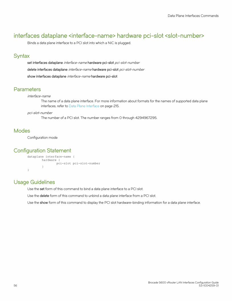
interfaces dataplane <interface-name> hardware pci-slot <slot-number>Binds a data plane interface to a PCI slot into which a NIC is plugged.
Syntaxset interfaces dataplane interface-name hardware pci-slot pci-slot-number
delete interfaces dataplane interface-name hardware pci-slot pci-slot-number
show interfaces dataplane interface-name hardware pci-slot
Parametersinterface-name
The name of a data plane interface. For more information about formats for the names of supported data planeinterfaces, refer to Data Plane Interface on page 215.
pci-slot-numberThe number of a PCI slot. The number ranges from 0 through 4294967295.
ModesConfiguration mode
Configuration Statementdataplane interface-name { hardware { pci-slot pci-slot-number }}
Usage GuidelinesUse the set form of this command to bind a data plane interface to a PCI slot.
Use the delete form of this command to unbind a data plane interface from a PCI slot.
Use the show form of this command to display the PCI slot hardware-binding information for a data plane interface.
Data Plane Interfaces Commands
Brocade 5600 vRouter LAN Interfaces Configuration Guide56 53-1004259-01
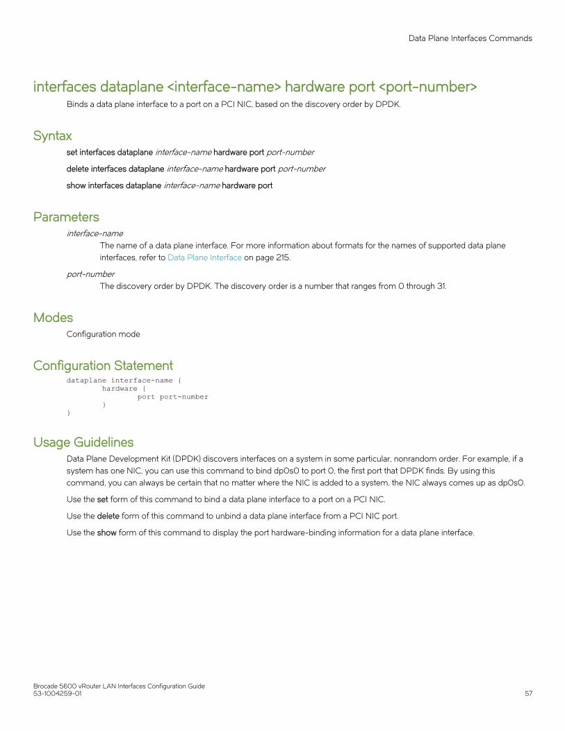
interfaces dataplane <interface-name> hardware port <port-number>Binds a data plane interface to a port on a PCI NIC, based on the discovery order by DPDK.
Syntaxset interfaces dataplane interface-name hardware port port-number
delete interfaces dataplane interface-name hardware port port-number
show interfaces dataplane interface-name hardware port
Parametersinterface-name
The name of a data plane interface. For more information about formats for the names of supported data planeinterfaces, refer to Data Plane Interface on page 215.
port-numberThe discovery order by DPDK. The discovery order is a number that ranges from 0 through 31.
ModesConfiguration mode
Configuration Statementdataplane interface-name { hardware { port port-number }}
Usage GuidelinesData Plane Development Kit (DPDK) discovers interfaces on a system in some particular, nonrandom order. For example, if asystem has one NIC, you can use this command to bind dp0s0 to port 0, the first port that DPDK finds. By using thiscommand, you can always be certain that no matter where the NIC is added to a system, the NIC always comes up as dp0s0.
Use the set form of this command to bind a data plane interface to a port on a PCI NIC.
Use the delete form of this command to unbind a data plane interface from a PCI NIC port.
Use the show form of this command to display the port hardware-binding information for a data plane interface.
Data Plane Interfaces Commands
Brocade 5600 vRouter LAN Interfaces Configuration Guide53-1004259-01 57
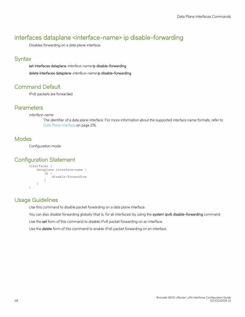
interfaces dataplane <interface-name> ip disable-forwardingDisables forwarding on a data plane interface.
Syntaxset interfaces dataplane interface-name ip disable-forwarding
delete interfaces dataplane interface-name ip disable-forwarding
Command DefaultIPv6 packets are forwarded.
Parametersinterface-name
The identifier of a data plane interface. For more information about the supported interface name formats, refer to Data Plane Interface on page 215.
ModesConfiguration mode
Configuration Statementinterfaces { dataplane interface-name { ip { disable-forwarding } }}
Usage GuidelinesUse this command to disable packet forwarding on a data plane interface.
You can also disable forwarding globally (that is, for all interfaces) by using the system ipv6 disable-forwarding command.
Use the set form of this command to disable IPv6 packet forwarding on an interface.
Use the delete form of this command to enable IPv6 packet forwarding on an interface.
Data Plane Interfaces Commands
Brocade 5600 vRouter LAN Interfaces Configuration Guide58 53-1004259-01
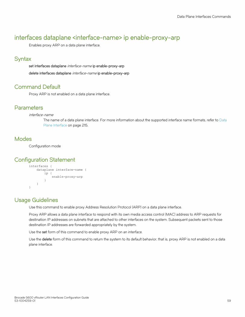
interfaces dataplane <interface-name> ip enable-proxy-arpEnables proxy ARP on a data plane interface.
Syntaxset interfaces dataplane interface-name ip enable-proxy-arp
delete interfaces dataplane interface-name ip enable-proxy-arp
Command DefaultProxy ARP is not enabled on a data plane interface.
Parametersinterface-name
The name of a data plane interface. For more information about the supported interface name formats, refer to DataPlane Interface on page 215.
ModesConfiguration mode
Configuration Statementinterfaces { dataplane interface-name { ip { enable-proxy-arp } }}
Usage GuidelinesUse this command to enable proxy Address Resolution Protocol (ARP) on a data plane interface.
Proxy ARP allows a data plane interface to respond with its own media access control (MAC) address to ARP requests fordestination IP addresses on subnets that are attached to other interfaces on the system. Subsequent packets sent to thosedestination IP addresses are forwarded appropriately by the system.
Use the set form of this command to enable proxy ARP on an interface.
Use the delete form of this command to return the system to its default behavior, that is, proxy ARP is not enabled on a dataplane interface.
Data Plane Interfaces Commands
Brocade 5600 vRouter LAN Interfaces Configuration Guide53-1004259-01 59
interfaces dataplane <interface-name> ip pim mode <mode>Specifies the PIM on a data plane interface.
Syntaxset interfaces dataplane interface-name ip pim mode mode
Parametersinterface-name
The name of a data plane interface. For more information about the supported interface name formats, refer to DataPlane Interface on page 215.
modeThe PIM mode for an interface. The mode is as follows:dense: Enable PIM dense mode.dense-passive: Enable passive operation for PIM dense mode.sparse: Enable PIM sparse mode.sparse-passive: Enable passive operation for PIM sparse mode.
ModesConfiguration mode
Configuration Statementinterfaces { dataplane interface-name { ip { pim { mode sparse } } }}
Usage GuidelinesUse the set form of this command to specify the PIM mode on a data plane interface.
Data Plane Interfaces Commands
Brocade 5600 vRouter LAN Interfaces Configuration Guide60 53-1004259-01
interfaces dataplane <interface-name> ip rpf-checkEnables the policy for reverse-path filter.
Syntaxset interfaces dataplane interface-name ip rpf-check { strict | loose | disable }
delete interfaces dataplane interface_name ip rpf-check [ strict | loose | disable ]
show interfaces dataplane interface_name ip rpf-check
Parametersinterface-name
The name of a data plane interface. For more information about the supported interface name formats, refer to DataPlane Interface on page 215.
strictAn ingress filter using a dynamic access list. According to RFC 3704.
looseAn ingress filter that checks for the presence of a source route. According to RFC 3704.
disableNo source validation.
ModesConfiguration mode
Configuration Statementinterfaces { dataplane interface-name { ip { rpf-check strict loose disable } }}
Usage GuidelinesUse this command to enable the policy for reverse-path filter.
Use the set form of this command to enable the policy for reverse-path filter.
Use the delete form of this command to delete the policy for reverse-path filter.
Use the show form of this command to display the policy for reverse-path filter.
Data Plane Interfaces Commands
Brocade 5600 vRouter LAN Interfaces Configuration Guide53-1004259-01 61
interfaces dataplane <interface-name> ipv6 addressAssigns an IPv6 address to a data plane interface.
Syntaxset interfaces dataplane interface-name ipv6 address [ autoconf | eui64 ipv6prefix | link-local ipv6address]
delete interfaces dataplane interface-name ipv6 address [ autoconf | eui64 ipv6prefix | link-local ipv6address ]
show interfaces dataplane interface-name ipv6 address [ autoconf | eui64 ]
Parametersinterface-name
The name of a data plane interface. For more information about the supported interface name formats, refer to DataPlane Interface on page 215.
autoconfGenerates an IPv6 address using the SLAAC protocol. Use this keyword if the interface is performing a “host” functionrather than a “router” function. You can specify this keyword in addition to static IPv6, static IPv4, or IPv4 DHCPaddresses on the interface.
eui64 ipv6prefixSpecifies the 64-bit IPv6 address prefix that is used to configure an IPv6 address in EUI-64 format. The systemconcatenates this prefix with a 64-bit EUI-64 value that is derived from the 48-bit MAC address of the interface.
link-local ipv6addressSpecifies the IPv6 address that is valid only for communication within the local broadcast domain.
ModesConfiguration mode
Configuration Statementinterfaces { dataplane interface-name { ipv6 { address { autoconf eui64 ipv6prefix link-local ipv6address } } } }
Usage GuidelinesUse this command to assign an IPv6 address to a data plane interface.
Use the autoconf keyword to direct the system to automatically configure (autoconfigure) the address, using the StatelessAddress Autoconfiguration (SLAAC) protocol defined in RFC 4862. Alternatively, you can use the eui64 keyword with an IPv6address prefix so that the system constructs the IPv6 address.
Data Plane Interfaces Commands
Brocade 5600 vRouter LAN Interfaces Configuration Guide62 53-1004259-01
If you want the system to use SLAAC to acquire an address on the interface, then in addition to setting this parameter, youmust also disable IPv6 forwarding, either globally (by using the system ipv6 disable-forwarding command) or specifically on theinterface (by using interfaces dataplane <interface-name> ipv6 disable-forwarding on page 64).
Use the link-local keyword to explicitly configure a specific link-local address, which then replaces any system generated link-local address.
Use the set form of this command to assign an IPv6 address to a data plane interface.
Use the delete form of this command to delete an IPv6 address from a data plane interface.
Use the show form of this command to display IPv6 address configuration settings.
Data Plane Interfaces Commands
Brocade 5600 vRouter LAN Interfaces Configuration Guide53-1004259-01 63
interfaces dataplane <interface-name> ipv6 disable-forwardingDisables IPv6 forwarding on a data plane interface.
Syntaxset interfaces dataplane interface-name ipv6 disable-forwarding
delete interfaces dataplane interface-name ipv6 disable-forwarding
Command DefaultIPv6 packets are forwarded.
Parametersinterface-name
The name of a data plane interface. For more information about the supported interface name formats, refer to DataPlane Interface on page 215.
ModesConfiguration mode
Configuration Statementinterfaces { dataplane interface-name { ipv6 { disable-forwarding } }}
Usage GuidelinesUse this command to disable IPv6 packet forwarding on a data plane interface.
You can also disable IPv6 forwarding globally (that is, for all interfaces) by using the system ipv6 disable-forwarding command.
Use the set form of this command to disable IPv6 packet forwarding on an interface.
Use the delete form of this command to enable IPv6 packet forwarding on an interface.
Data Plane Interfaces Commands
Brocade 5600 vRouter LAN Interfaces Configuration Guide64 53-1004259-01
interfaces dataplane <interface-name> ipv6 dup-addr-detect-transmits<num>
Specifies the number of NS packets to transmit as part of the DAD process.
Syntaxset interfaces dataplane interface-name ipv6 dup-addr-detect-transmits num
delete interfaces dataplane interface-name ipv6 dup-addr-detect-transmits
Command DefaultOne NS packet is transmitted as part of the DAD process.
Parametersinterface-name
The name of a data plane interface. For more information about the supported interface name formats, refer to DataPlane Interface on page 215.
numThe number of NS packets to transmit as part of the DAD process. The number ranges from 1 through n. The defaultnumber is 1.
ModesConfiguration mode
Configuration Statementinterfaces { dataplane interface-name { ipv6 { dup-addr-detect-transmits num } } }
Usage GuidelinesUse this command to specify the number of Neighbor Solicitation (NS) packets to transmit as part of the Duplicate AddressDetection (DAD) process.
Use the set form of this command to specify the number of NS packets to transmit on an interface.
Use the delete form of this command to delete the transmission number from an interface and transmit the default number ofone NS packet.
Data Plane Interfaces Commands
Brocade 5600 vRouter LAN Interfaces Configuration Guide53-1004259-01 65
interfaces dataplane <interface-name> ipv6 router-advertSpecifies the router advertisements to be sent from a data plane interface.
Syntaxset interfaces dataplane interface-name ipv6 router-advert [ cur-hop-limit limit ] [ default-lifetime lifetime ] [ default-preference
preference ] [ link-mtu mtu ] [ managed-flag state ] [ max-interval interval ] [ min-interval interval ] [ other-config-flag state ][ prefix ipv6net [ autonomous-flag state | on-link-flag state | preferred-lifetime lifetime | valid-lifetime lifetime ] ][ reachable-time time ] [ retrans-timer time ] [ send-advert state ]
delete interfaces dataplane interface-name ipv6 router-advert [ cur-hop-limit ] [ default-lifetime ] [ default-preference ] [ link-mtu ] [ managed-flag ] [ max-interval ] [ min-interval ] [ other-config-flag ] [ prefix ipv6net [ autonomous-flag | on-link-flag |preferred-lifetime | valid-lifetime ] ] [ reachable-time ] [ retrans-timer ] [ send-advert ]
Command DefaultRouter advertisements are not sent on an interface.
Parametersinterface-name
The name of a data plane interface. For more information about the supported interface name formats, refer to DataPlane Interface on page 215.
cur-hop-limit limitSpecifies the hop-count field of the IP header for outgoing (unicast) IP packets. This value is placed in the Hop Countfield of the IP header for outgoing (unicast) IP packets. The range is 0 to 255. The default is 64. A limit of 0 meansunspecified by the router.
default-lifetime lifetimeSpecifies the lifetime, in seconds, that is associated with the default router. A lifetime of 0 indicates that the router isnot a default router. The lifetime ranges from the value that is configured for the max-interval option to 9000 (18.2hours). If the lifetime is not configured, the value for this timer is three times max-interval.
default-preference preferenceSpecifies the preference that is associated with the default router. The preference is low, medium, or high. The defaultpreference is medium.
link-mtu mtuSpecifies the MTU to be advertised for the link. The MTU is 0 or ranges from 1280 through the maximum MTU forthe type of link, as defined in RFC 2464. The default MTU is 0, which means the MTU is not specified in the routeradvertisement message. That is because it is expected that the MTU is configured directly on the interface itself andnot for routing advertisements. You can configure this option when the link MTU is not well known.If the MTU that is set here does not match the MTU that is configured on the interface, the system issues a warningbut does not fail.
managed-flag stateWhether to use the administered protocol for address autoconfiguration. The state is either of the following:true: Hosts use the administered (stateful) protocol for address autoconfiguration in addition to any addressesautoconfigured using stateless address autoconfiguration.false: Hosts use only stateless address autoconfiguration.
Data Plane Interfaces Commands
Brocade 5600 vRouter LAN Interfaces Configuration Guide66 53-1004259-01

The default state is false.
max-interval intervalSpecifies the maximum time, in seconds, that is allowed between sending unsolicited multicast router advertisementsfrom the interface. The interval ranges from 4 through 1800. The default is 600 (10 minutes).
min-interval intervalSpecifies the minimum time, in seconds, that is allowed between sending unsolicited multicast router advertisementsfrom the interface. The interval ranges from 3 through 0.75 times the max-interval option. The default interval is 0.33times max-interval.
other-config-flag stateSpecifies that the interface use the administered (stateful) protocol for autoconfiguration of nonaddress information, asdefined in RFC 4862. The state is either of the following:true: Hosts use the administered protocol for autoconfiguration of nonaddress information.false: Hosts use stateless autoconfiguration of nonaddress information.The default state is false.
prefix ipv6netMultinode. Specifies the IPv6 prefix to be advertised on the IPv6 interface, in the format ipv6-address/prefix.You can define more than one IPv6 prefix by configuring multiple prefix configuration nodes.
autonomous-flag stateSpecifies whether the prefix can be used for autonomous address configuration as defined in RFC 4862. The state iseither of the following:true: The prefix can be used for autonomous address configuration.false: The prefix cannot be used for autonomous address configuration.The default state is true.
on-link-flag stateSpecifies whether the prefix can be used for onlink determination, as defined in RFC 4862. The state is either of thefollowing:true: The prefix can be used for onlink determination.false: The advertisement makes no statement about onlink or off-link properties of the prefix. For instance, the prefixmight be used for address configuration with some addresses belonging to the prefix being onlink and others beingoff-link.The default state is true.
preferred-lifetime lifetimeSpecifies the length of time, in seconds, that the addresses generated from the prefix by Stateless AddressAutoconfiguration (SLAAC) is to remain preferred, as defined in RFC 4862. The interval is with respect to the time thepacket is sent. The lifetime ranges from 1 through 4294967296 plus the infinity keyword, which represents forever.(The actual value of infinity is a byte in which all bits are set to 1s: 0XFFFFFFFF.) The default lifetime is 604800 (7days).
valid-lifetime lifetimeSpecifies the length of time, in seconds, that the prefix is valid for onlink determination, as defined in RFC 4862. Theinterval is with respect to the time the packet is sent. The lifetime ranges from 1 through 4294967296 plus the infinitykeyword, which represents forever. (The actual value of infinity is a byte in which all bits are set to 1s: 0XFFFFFFFF.)The default lifetime is 2592000 (30 days).
reachable-time timeSpecifies the length of time, in milliseconds, for which the system assumes a neighbor is reachable after havingreceived a reachability confirmation. This time is used by address resolution and the Neighbor Unreachability
Data Plane Interfaces Commands
Brocade 5600 vRouter LAN Interfaces Configuration Guide53-1004259-01 67
Detection algorithm (see Section 7.3 of RFC 2461). The time ranges from 0 through 3600000, where a value of 0means the reachable time is not specified in the router advertisement message. The default time is 0.
retrans-timer timeSpecifies the length of time, in milliseconds, between retransmitted NS messages. This time is used by addressresolution and the Neighbor Unreachability Detection algorithm (see Sections 7.2 and 7.3 of RFC 2461). The timeranges from 0 through 4294967295, where a value of 0 means the retransmit time is not specified in the routeradvertisement message. The default time is 0.
send-advert stateSpecifies whether router advertisements are to be sent from this interface. The state is either of the following:true: Sends router advertisements from this interface.false: Does not send router advertisements from this interface. If a state is in effect, parameters in this configurationsubtree are still used to configure the local implementation parameters.The default state is true.
ModesConfiguration mode
Configuration Statementinterfaces { dataplane interface-name { ipv6 { router-advert { cur-hop-limit limit default-lifetime lifetime default-preference preference link-mtu mtu managed-flag state max-interval interval min-interval interval other-config-flag state prefix ipv6net { autonomous-flag state on-link-flag state preferred-lifetime lifetime valid-lifetime lifetime } reachable-time time retrans-timer time send-advert state } } }}
Usage GuidelinesUse this command to specify the router advertisements to be sent from a data plane interface.
Router advertisements are sent by IPv6 routers to advertise their existence to hosts on the network. IPv6 hosts do not sendrouter advertisements.
If the router-advert node of the configuration tree is missing, router advertisements are not sent. In addition, if IPv6 forwardingis disabled either globally (by using the system ipv6 disable-forwarding command) or on the interface (by using interfacesdataplane <interface-name> ipv6 disable-forwarding on page 64), router advertisements are not sent.
Data Plane Interfaces Commands
Brocade 5600 vRouter LAN Interfaces Configuration Guide68 53-1004259-01

Most router advertisement parameters are required by either the Neighbor Discovery (ND) protocol or the Stateless AddressAutoconfiguration (SLAAC) protocol. These parameters are used both locally for the IPv6 implementation and become part ofthe RA messages sent to hosts on the network so that they can be configured appropriately.
Use the set form of this command to create the router-advert configuration node and begin to send router advertisements.
Use the delete form of this command to delete the router-advert configuration node and stop sending router advertisements.
Use the show form of this command to display router advertisement configuration.
Data Plane Interfaces Commands
Brocade 5600 vRouter LAN Interfaces Configuration Guide53-1004259-01 69
interfaces dataplane <interface-name> mac <mac-addr>Sets the MAC address of a data plane interface.
Syntaxset interfaces dataplane interface-name mac mac-addr
delete interfaces dataplane interface-name mac
Command DefaultThe default MAC address for an interface is the factory-set MAC address.
Parametersinterface-name
The name of a data plane interface. For more information about the supported interface name formats, refer to DataPlane Interface on page 215.
mac-addrA MAC address. The format of the address is six 8-bit numbers, separated by colons, in hexadecimal; for example,00:0a:59:9a:f2:ba.
ModesConfiguration mode
Configuration Statementinterfaces { dataplane interface-name { mac mac-addr }}
Usage GuidelinesUse this command to set the media access control (MAC) address of a data plane interface.
Some data plane interfaces provide the ability to change their MAC addresses. This command allows you to change the MACaddresses of these interfaces.
Use the set form of this command to set the MAC address of an interface.
Use the delete form of this command to delete the MAC address of an interface, restoring the factory-assigned MAC address.
Data Plane Interfaces Commands
Brocade 5600 vRouter LAN Interfaces Configuration Guide70 53-1004259-01
interfaces dataplane <interface-name> mtu <mtu>Sets the size of the MTU for a data plane interface.
Syntaxset interfaces dataplane interface-name mtu mtu
delete interfaces dataplane interface-name mtu
show interfaces dataplane interface-name mtu
Command DefaultThe default size of the MTU is 1500.
Parametersinterface-name
The name of a data plane interface. For more information about the supported interface name formats, refer to DataPlane Interface on page 215.
mtuThe size of the MTU, in octets, for the interface as a whole, including any logical interfaces configured for it. The size ofthe MTU ranges from 68 through 9000.
ModesConfiguration mode
Configuration Statementinterfaces { dataplane interface-name { mtu mtu }}
Usage GuidelinesUse this command to set the size of the maximum transmission unit (MTU) for a data plane interface.
During forwarding, IPv4 packets larger than the MTU are fragmented unless the “Don't Fragment” (DF) bit is set in the IPheader. In that case, the packets are dropped and an ICMP “fragmentation needed” message is returned to the sender.
Note that MTU sizes larger than 1500 cause the system to generate “jumbo frames,” which are not compatible with some dataplane interface cards and devices.
If the data plane interface is part of an Ethernet link bond, MTU settings for the bonded link override MTU settings for thephysical interface.
Use the set form of this command to specify the size of the MTU.
Use the delete form of this command to delete the size of the MTU and restore the default size of 1500.
Use the show form of this command to display the current size of the MTU.
Data Plane Interfaces Commands
Brocade 5600 vRouter LAN Interfaces Configuration Guide53-1004259-01 71
interfaces dataplane <interface-name> vif <vif-id> dhcp-options no-rfc3442Disables support for the classless static route option for DHCP on a virtual interface.
Syntaxset interfaces dataplane interface-name vif vif-id dhcp-options no-rfc3442
delete interfaces dataplane interface-name vif vif-id dhcp-options no-rfc3442
show interfaces dataplane interface-name vif vif-id dhcp-options
Command DefaultThe classless static route option for DHCP is enabled.
Parametersinterface-name
The Brocade vRouter can only use interfaces that are available to the operating system kernel (that is, interfaces thatphysically exist on the system) and have been created in the configuration tree and configured with an IP address.The Brocade vRouter automatically creates configuration nodes for all available physical interfaces on startup.If you want to use an interface with a specific function (say, BGP) the interface must be enabled within theconfiguration node for that function (for example, within the BGP configuration node).
vif-idMultinode. The ID of a virtual interface. The ID ranges from 1 through 4094.
no-rfc3442Removes the classless static route option (121) from the parameter request list that a DHCP client sends to the DHCPserver. For further information, refer to RFC 3442 at https://tools/ietf.org/html/refc3442.
ModesConfiguration mode
Configuration Statementinterfaces { dataplane interface-name { vif vif-id { dhcp-options { no-rfc3442 } } }}
Usage Guidelines
NOTEThis command is relevant only if the dhcp option has been set by using interfaces dataplane <interface-name> vif <vif-id> address on page 121.
Data Plane Interfaces Commands
Brocade 5600 vRouter LAN Interfaces Configuration Guide72 53-1004259-01

NOTENormally, this command is not required. It would be used only if the remote DHCP server is configured to provideclassless static routes, but these routes are not required on the router that is configured to use the DHCP address.
Use the set form of this command to disable support for the DHCP classless static route option on a virtual interface.
Use the delete form of this command to re-enable support for the DHCP classless static route option on a virtual interface.
Use the show form of this command to display the status of the DHCP classless static route option on a virtual interface.
Data Plane Interfaces Commands
Brocade 5600 vRouter LAN Interfaces Configuration Guide53-1004259-01 73
interfaces dataplane <interface-name> vif <vif-id> policy qos <name>Configures a QoS policy for a VLAN on a virtual interface.
Syntaxset interfaces dataplane interface-name vif vif-id policy qos name
delete interfaces dataplane interface-name vif vif-id policy qos
Parametersinterface-name
The Brocade vRouter can only use interfaces that are available to the operating system kernel (that is, interfaces thatphysically exist on the system) and have been created in the configuration tree.The Brocade vRouter automatically creates configuration nodes for all available physical interfaces on startup.
vif-idMultinode. The ID of a virtual interface. The ID ranges from 1 through 4094.
nameSpecifies a QoS policy name.
ModesConfiguration mode
Configuration Statementinterfaces { dataplane interface-name { vif vif-id { policy { qos name } } }}
Usage GuidelinesUse the set form of this command to configure a QoS policy for a VLAN on a virtual interface. Before using this command, usethe set interfaces dataplane interface-name policy qos policy-name command to set a port level QoS policy. The command isdescribed in Brocade 5600 vRouter QoS Reference Guide
Use the delete form of this command to remove the QoS policy on the virtual interface.
Data Plane Interfaces Commands
Brocade 5600 vRouter LAN Interfaces Configuration Guide74 53-1004259-01

interfaces dataplane <interface-name> vrrp vrrp-group <vrrp-group-id>notify bgp
Sets the BGP update notification when the path taken by the outgoing traffic changes.
Syntaxset interfaces dataplane interface-name vrrp vrrp-group vrrp-group-id notify bgp
delete interfaces dataplane interface-name vrrp
show interfaces dataplane interface-name vrrp
Parametersinterface-name
The name of a data plane interface. For more information about the supported interface name formats, refer to DataPlane Interface on page 215.
vrrp-group-idThe ID of a vrrp downlink group instance.
ModesConfiguration mode
Configuration Statementinterfaces { dataplane interface-name { vrrp { vrrp-group vrrp-group-id { notify { bgp } } } }}
Usage GuidelinesIn certain topologies that involve VRRP in downlink LANs and eBGP to ISP in uplink LANs, symmetric routing can be achievedby influencing or changing the path taken by incoming traffic according to the path taken by outgoing traffic.
The edge topology described here can have two 5600 vRouters that act as VRRP Master and Backup pair for the downlinkLAN of the end hosts. Both VRRP Master and Backup pair routers are connected to an ISP gateway router, each througheBGP. This configuration provides two possible outgoing and incoming paths for the traffic.
When VRRP state changes in downlink, that is, when the path taken by the outgoing traffic changes, vRouters send BGPupdates to respective eBGP ISP gateway peers. The update notification contains Multi-Exit Discriminator (MED) or prepend-as-path changes according to the configuration to influence the change in BGP best paths for incoming traffic.
The as-path-string that is used on the active path or the path that includes the VRRP elected master is NONE, that is, no AS-path prepended.
Data Plane Interfaces Commands
Brocade 5600 vRouter LAN Interfaces Configuration Guide53-1004259-01 75

This configuration is required to enable the symmetric routing on vRouters in association with either of the followingcommands:
∙ set protocols bgp asn neighbor id vrrp-failover vrrp-group vrrp-group-id med med-value
∙ set protocols bgp asn neighbor id vrrp-failover vrrp-group vrrp-group-id prepend-as as-path-string
Data Plane Interfaces Commands
Brocade 5600 vRouter LAN Interfaces Configuration Guide76 53-1004259-01
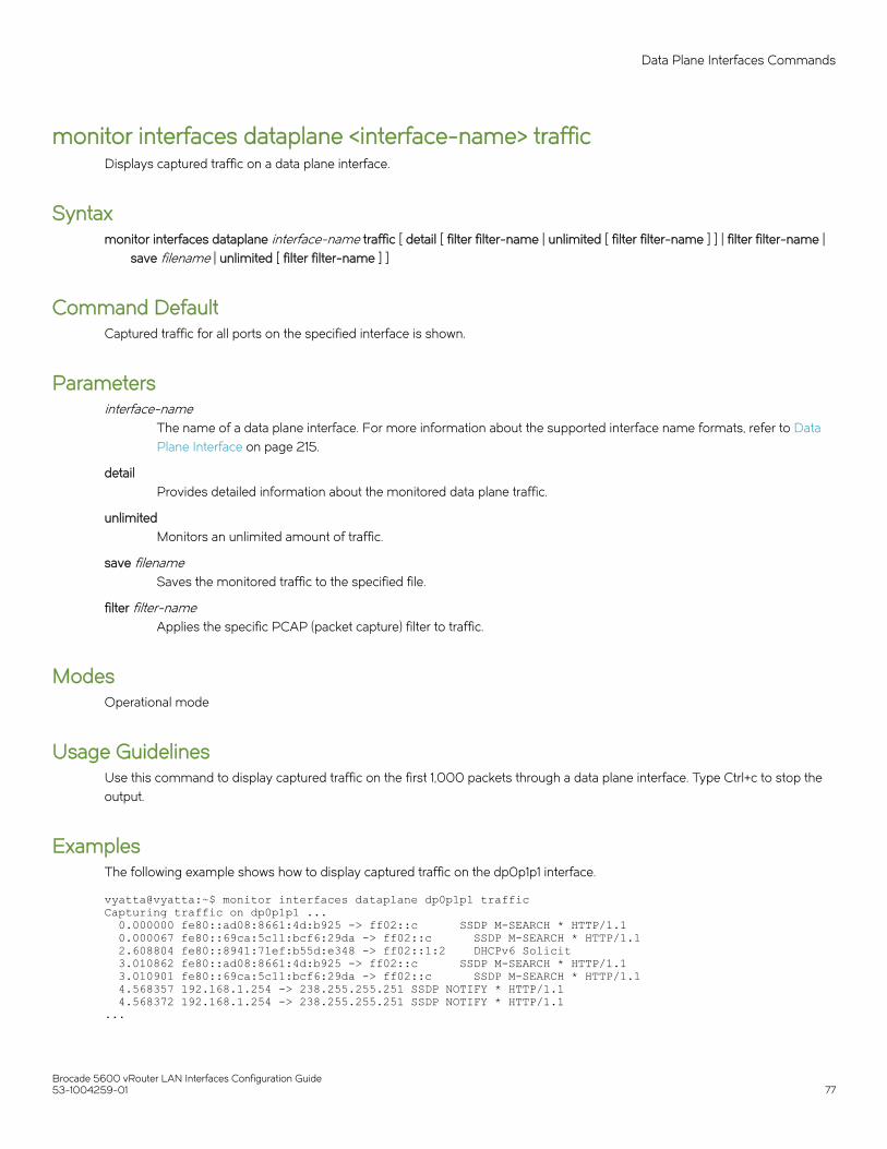
monitor interfaces dataplane <interface-name> trafficDisplays captured traffic on a data plane interface.
Syntaxmonitor interfaces dataplane interface-name traffic [ detail [ filter filter-name | unlimited [ filter filter-name ] ] | filter filter-name |
save filename | unlimited [ filter filter-name ] ]
Command DefaultCaptured traffic for all ports on the specified interface is shown.
Parametersinterface-name
The name of a data plane interface. For more information about the supported interface name formats, refer to DataPlane Interface on page 215.
detailProvides detailed information about the monitored data plane traffic.
unlimitedMonitors an unlimited amount of traffic.
save filenameSaves the monitored traffic to the specified file.
filter filter-nameApplies the specific PCAP (packet capture) filter to traffic.
ModesOperational mode
Usage GuidelinesUse this command to display captured traffic on the first 1,000 packets through a data plane interface. Type Ctrl+c to stop theoutput.
ExamplesThe following example shows how to display captured traffic on the dp0p1p1 interface.
vyatta@vyatta:~$ monitor interfaces dataplane dp0p1p1 trafficCapturing traffic on dp0p1p1 ... 0.000000 fe80::ad08:8661:4d:b925 -> ff02::c SSDP M-SEARCH * HTTP/1.1 0.000067 fe80::69ca:5c11:bcf6:29da -> ff02::c SSDP M-SEARCH * HTTP/1.1 2.608804 fe80::8941:71ef:b55d:e348 -> ff02::1:2 DHCPv6 Solicit 3.010862 fe80::ad08:8661:4d:b925 -> ff02::c SSDP M-SEARCH * HTTP/1.1 3.010901 fe80::69ca:5c11:bcf6:29da -> ff02::c SSDP M-SEARCH * HTTP/1.1 4.568357 192.168.1.254 -> 238.255.255.251 SSDP NOTIFY * HTTP/1.1 4.568372 192.168.1.254 -> 238.255.255.251 SSDP NOTIFY * HTTP/1.1...
Data Plane Interfaces Commands
Brocade 5600 vRouter LAN Interfaces Configuration Guide53-1004259-01 77
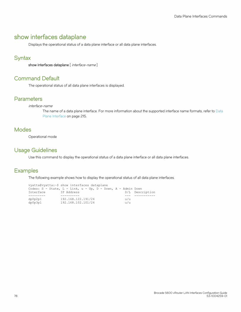
show interfaces dataplaneDisplays the operational status of a data plane interface or all data plane interfaces.
Syntaxshow interfaces dataplane [ interface-name ]
Command DefaultThe operational status of all data plane interfaces is displayed.
Parametersinterface-name
The name of a data plane interface. For more information about the supported interface name formats, refer to DataPlane Interface on page 215.
ModesOperational mode
Usage GuidelinesUse this command to display the operational status of a data plane interface or all data plane interfaces.
ExamplesThe following example shows how to display the operational status of all data plane interfaces.
vyatta@vyatta:~$ show interfaces dataplaneCodes: S - State, L - Link, u - Up, D - Down, A - Admin DownInterface IP Address S/L Description--------- ---------- --- -----------dp0p2p1 192.168.122.191/24 u/u dp0p3p1 192.168.102.101/24 u/u
Data Plane Interfaces Commands
Brocade 5600 vRouter LAN Interfaces Configuration Guide78 53-1004259-01
show interfaces dataplane detailDisplays detailed statistics and configuration information about all data plane interfaces.
Syntaxshow interfaces dataplane detail
ModesOperational mode
Usage GuidelinesUse this command to display detailed statistics and configuration information about all data plane interfaces.
Data Plane Interfaces Commands
Brocade 5600 vRouter LAN Interfaces Configuration Guide53-1004259-01 79
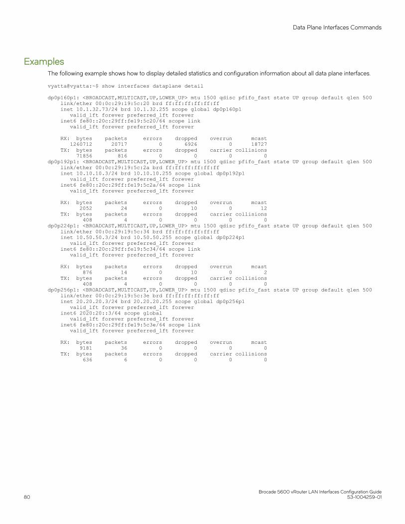
ExamplesThe following example shows how to display detailed statistics and configuration information about all data plane interfaces.
vyatta@vyatta:~$ show interfaces dataplane detail
dp0p160p1: <BROADCAST,MULTICAST,UP,LOWER_UP> mtu 1500 qdisc pfifo_fast state UP group default qlen 500 link/ether 00:0c:29:19:5c:20 brd ff:ff:ff:ff:ff:ff inet 10.1.32.73/24 brd 10.1.32.255 scope global dp0p160p1 valid_lft forever preferred_lft forever inet6 fe80::20c:29ff:fe19:5c20/64 scope link valid_lft forever preferred_lft forever
RX: bytes packets errors dropped overrun mcast 1260712 20717 0 6926 0 18727 TX: bytes packets errors dropped carrier collisions 71856 816 0 0 0 0dp0p192p1: <BROADCAST,MULTICAST,UP,LOWER_UP> mtu 1500 qdisc pfifo_fast state UP group default qlen 500 link/ether 00:0c:29:19:5c:2a brd ff:ff:ff:ff:ff:ff inet 10.10.10.3/24 brd 10.10.10.255 scope global dp0p192p1 valid_lft forever preferred_lft forever inet6 fe80::20c:29ff:fe19:5c2a/64 scope link valid_lft forever preferred_lft forever
RX: bytes packets errors dropped overrun mcast 2052 24 0 10 0 12 TX: bytes packets errors dropped carrier collisions 408 4 0 0 0 0dp0p224p1: <BROADCAST,MULTICAST,UP,LOWER_UP> mtu 1500 qdisc pfifo_fast state UP group default qlen 500 link/ether 00:0c:29:19:5c:34 brd ff:ff:ff:ff:ff:ff inet 10.50.50.3/24 brd 10.50.50.255 scope global dp0p224p1 valid_lft forever preferred_lft forever inet6 fe80::20c:29ff:fe19:5c34/64 scope link valid_lft forever preferred_lft forever
RX: bytes packets errors dropped overrun mcast 876 14 0 10 0 2 TX: bytes packets errors dropped carrier collisions 408 4 0 0 0 0dp0p256p1: <BROADCAST,MULTICAST,UP,LOWER_UP> mtu 1500 qdisc pfifo_fast state UP group default qlen 500 link/ether 00:0c:29:19:5c:3e brd ff:ff:ff:ff:ff:ff inet 20.20.20.3/24 brd 20.20.20.255 scope global dp0p256p1 valid_lft forever preferred_lft forever inet6 2020:20::3/64 scope global valid_lft forever preferred_lft forever inet6 fe80::20c:29ff:fe19:5c3e/64 scope link valid_lft forever preferred_lft forever
RX: bytes packets errors dropped overrun mcast 9181 36 0 0 0 0 TX: bytes packets errors dropped carrier collisions 636 6 0 0 0 0
Data Plane Interfaces Commands
Brocade 5600 vRouter LAN Interfaces Configuration Guide80 53-1004259-01
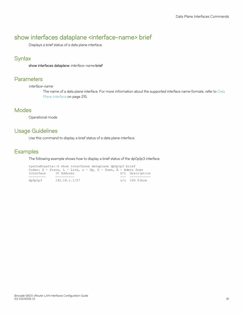
show interfaces dataplane <interface-name> briefDisplays a brief status of a data plane interface.
Syntaxshow interfaces dataplane interface-name brief
Parametersinterface-name
The name of a data plane interface. For more information about the supported interface name formats, refer to DataPlane Interface on page 215.
ModesOperational mode
Usage GuidelinesUse this command to display a brief status of a data plane interface.
ExamplesThe following example shows how to display a brief status of the dp0p1p3 interface.
vyatta@vyatta:~$ show interfaces dataplane dp0p1p3 briefCodes: S - State, L - Link, u - Up, D - Down, A - Admin DownInterface IP Address S/L Description--------- ---------- --- -----------dp0p1p3 192.18.1.1/27 u/u 10G Fibre
Data Plane Interfaces Commands
Brocade 5600 vRouter LAN Interfaces Configuration Guide53-1004259-01 81
show interfaces dataplane <interface-name> physicalDisplays information about the physical layer of a data plane interface.
Syntaxshow interfaces dataplane interface-name physical
Parametersinterface-name
The name of a data plane interface. For more information about the supported interface name formats, refer to DataPlane Interface on page 215.
ModesOperational mode
Usage GuidelinesUse this command to display information about the physical layer of a data plane interface.
Data Plane Interfaces Commands
Brocade 5600 vRouter LAN Interfaces Configuration Guide82 53-1004259-01
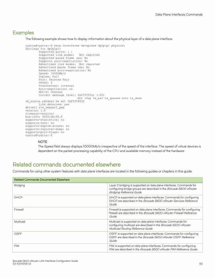
ExamplesThe following example shows how to display information about the physical layer of a data plane interface.
vyatta@vyatta:~$ show interfaces dataplane dp0p1p1 physicalSettings for dp0p1p1: Supported ports: [ ] Supported link modes: Not reported Supported pause frame use: No Supports auto-negotiation: No Advertised link modes: Not reported Advertised pause frame use: No Advertised auto-negotiation: No Speed: 10000Mb/s Duplex: Full Port: Twisted Pair PHYAD: 0 Transceiver: internal Auto-negotiation: on MDI-X: Unknown Current message level: 0xffffffa1 (-95) drv ifup tx_err tx_queued intr tx_donerx_status pktdata hw wol 0xffff8000 Link detected: yesdriver: rte_vmxnet3_pmdversion: 1.6firmware-version:bus-info: 0000:0b:00.0supports-statistics: nosupports-test: nosupports-eeprom-access: nosupports-register-dump: nosupports-priv-flags: novyatta@vyatta:~$
NOTEThe Speed field always displays 10000Mb/s irrespective of the speed of the interface. The speed of virtual devices isdependent on the packet processing capability of the CPU and available memory instead of the hardware.
Related commands documented elsewhereCommands for using other system features with data plane interfaces are located in the following guides or chapters in this guide.
Related Commands Documented Elsewhere
Bridging Layer 2 bridging is supported on data plane interfaces. Commands forconfiguring bridge groups are described in the Brocade 5600 vRouterBridging Reference Guide.
DHCP DHCP is supported on data plane interfaces. Commands for configuringDHCP are described in the Brocade 5600 vRouter Services ReferenceGuide.
Firewall Firewall is supported on data plane interfaces. Commands for configuringfirewall are described in the Brocade 5600 vRouter Firewall ReferenceGuide.
Multicast Multicast is supported on data plane interfaces. Commands forconfiguring multicast are described in the Brocade 5600 vRouterMulticast Routing Reference Guide
OSPF OSPF is supported on data plane interfaces. Commands for configuringOSPF are described in the Brocade 5600 vRouter OSPF ReferenceGuide.
PIM PIM is supported on data plane interfaces. Commands for configuringPIM are described in the Brocade 5600 vRouter PIM Reference Guide
Data Plane Interfaces Commands
Brocade 5600 vRouter LAN Interfaces Configuration Guide53-1004259-01 83

Related Commands Documented Elsewhere
Policy Based Routing Policy Based Routing is supported on data plane interfaces. Commandsfor configuring Policy Based Routing are described in the Brocade 5600vRouter Policy-based Routing Reference Guide.
QoS Quality of service traffic policies are supported on data plane interfaces.Commands for configuring QoS are described in the Brocade 5600vRouter QoS Reference Guide.
RIP RIP is supported on data plane interfaces. Commands for configuring RIPare described in the Brocade 5600 vRouter RIP Reference Guide.
RIPng RIPng is supported on data plane interfaces. Commands for configuringRIPng are described in the Brocade 5600 vRouter RIPng ReferenceGuide.
System interfaces Commands for showing the physical interfaces available on your systemare described in the Brocade 5600 vRouter Basic System ReferenceGuide.
VLAN interfaces 802.1Q VLAN operation is supported on data plane interfaces.Commands for configuring VLAN interfaces (vifs) are described in “DataPlane Interfaces on page 33.”
VRRP VRRP is supported on data plane interfaces and on VLAN interfacesconfigured under data plane interfaces. Commands for configuring VRRPare described in the Brocade 5600 vRouter High Availability ReferenceGuide.
Data Plane Interfaces Commands
Brocade 5600 vRouter LAN Interfaces Configuration Guide84 53-1004259-01
Ethernet Link Bonding Interface∙ Ethernet link bonding overview.................................................................................................................................................................................85∙ Ethernet bonding configuration examples..........................................................................................................................................................86
Ethernet link bonding overviewIn some operational scenarios, it makes sense to group multiple physical links together to create a larger virtual link. Grouping offers away to increase performance between two devices without having to pay for a higher-speed physical link, and to provide redundancy sothat connectivity still exists if a link fails. In a WAN, multilink Point-to-Point Protocol (MLPPP) is used to bundle multiple PPP links; in aLAN, Ethernet link bonding is used to bundle multiple Ethernet links.
Many implementations of Ethernet link bonding are nonstandard. The IEEE 802.3ad specification (now called IEEE 802.1ax) attempts toincrease standardization. The IEEE 802.3ad standard has been adopted to varying degrees by all manufacturers. This standard specifiesthe general properties of the link, and defines the Link Aggregation Control Protocol (LACP).
802.3ad LACP is an active protocol that runs on Ethernet links that are configured for bonding. LACP allows peers to negotiate theautomatic bonding of multiple links and helps detect situations in which one side is not configured correctly for link bonding. LACP alsoactively tests all physical connections between configured devices. Link failures can be detected even if other physical devices areattached to either end (for example, physical media converters) and would otherwise not show a link as down if a fault occurs in themiddle of the physical link. If a link fails, traffic is redistributed dynamically to the remaining links.
The 802.3ad standard specifies that all physical links composing the bonded virtual link are full-duplex and point-to-point. Violation ofeither assumption can cause unexpected behavior in the bonded link.
The 802.3ad standard specifies that all packets belonging to a “conversation” must travel across the same physical link and that nopackets may be duplicated. However, the abstraction of a conversation and the algorithm for assigning conversations to each link areincompletely specified. As a result, specific implementations vary, even between the ends of the bonded virtual link. This variance canlead to asymmetric traffic flow.
The number of links that can be bonded is limited by system capacity, especially memory. The Ethernet links in a bonded link need notbe all the same speed.
Physical links that are added to a bonded link do not have to be operational when they are added. In the configuration for the bondedlink, only the maximum transmission unit (MTU) is inherited from the bundle. That is, if you change the MTU of the bonded link, theMTU of the underlying Ethernet links is overridden. The remaining configuration is always taken from the configuration that is specifiedfor the individual Ethernet link. The exception is that a physical link cannot be assigned an IP address if it is to be added to a bond group.
You can include VLANs within a bonded link; however, bundling multiple VLANs together as a bonded trunk is not supported. Becausethe purpose of bonding is to improve availability and performance, the bonded link requires actual physical links as a base.
NOTEThe performance of a bonding interface is limited by the performance of a single CPU, not the line rate of the aggregatedinterfaces.
The following actions can cause unexpected behavior and are not supported:
∙ Deleting a member link from a bonding interface and adding it to a different bonding interface.
∙ Deleting a member link from a bonding interface and adding it to the same bonding interface.
∙ Deleting a member link from a bonding interface and using it as an unbonded dataplane interface.
∙ Deleting all member links from a bonding interface and deleting the bonding interface itself.
Brocade 5600 vRouter LAN Interfaces Configuration Guide53-1004259-01 85
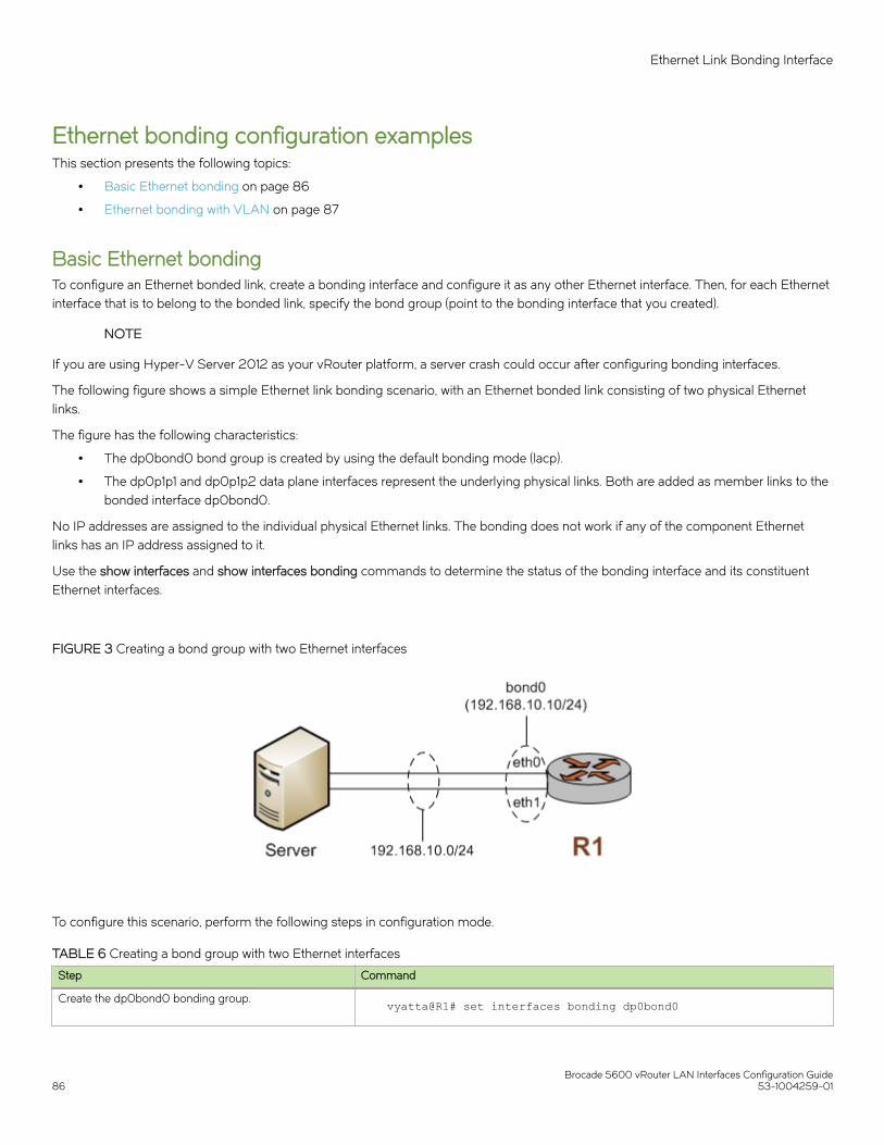
Ethernet bonding configuration examplesThis section presents the following topics:
∙ Basic Ethernet bonding on page 86
∙ Ethernet bonding with VLAN on page 87
Basic Ethernet bondingTo configure an Ethernet bonded link, create a bonding interface and configure it as any other Ethernet interface. Then, for each Ethernetinterface that is to belong to the bonded link, specify the bond group (point to the bonding interface that you created).
NOTE
If you are using Hyper-V Server 2012 as your vRouter platform, a server crash could occur after configuring bonding interfaces.
The following figure shows a simple Ethernet link bonding scenario, with an Ethernet bonded link consisting of two physical Ethernetlinks.
The figure has the following characteristics:
∙ The dp0bond0 bond group is created by using the default bonding mode (lacp).
∙ The dp0p1p1 and dp0p1p2 data plane interfaces represent the underlying physical links. Both are added as member links to thebonded interface dp0bond0.
No IP addresses are assigned to the individual physical Ethernet links. The bonding does not work if any of the component Ethernetlinks has an IP address assigned to it.
Use the show interfaces and show interfaces bonding commands to determine the status of the bonding interface and its constituentEthernet interfaces.
FIGURE 3 Creating a bond group with two Ethernet interfaces
To configure this scenario, perform the following steps in configuration mode.
TABLE 6 Creating a bond group with two Ethernet interfaces
Step Command
Create the dp0bond0 bonding group. vyatta@R1# set interfaces bonding dp0bond0
Ethernet Link Bonding Interface
Brocade 5600 vRouter LAN Interfaces Configuration Guide86 53-1004259-01
TABLE 6 Creating a bond group with two Ethernet interfaces (continued)
Step Command
Set the IP address for the bonding group to192.168.10.10/24.
vyatta@R1# set interfaces bonding dp0bond0 address 192.168.10.10/24
Add dp0p1p1 to the dp0bond0 bonding group. vyatta@R1# set interfaces dataplane dp0p1p1 bond-group dp0bond0
Add dp0p1p2 to the dp0bond0 bonding group. vyatta@R1# set interfaces dataplane dp0p1p2 bond-group dp0bond0
Commit the change. vyatta@R1# commit
Show the bonding group configuration. vyatta@R1# show interfaces bonding dp0bond0address 192.168.10.10/24
Show the dp0p1p1 configuration. vyatta@R1# show interfaces bonding dp0p1p1bond-group dp0bond0
Show the dp0p1p2 configuration. vyatta@R1# show interfaces bonding dp0p1p2bond-group dp0bond0
Ethernet bonding with VLANAfter a bonding interface is created, it is possible to create a VLAN within it. The following example is an extension of the previousexample with the addition of a VLAN. The resulting bonding interface contains both VLAN and nonVLAN traffic.
To configure this scenario, perform the following steps in configuration mode.
TABLE 7 Adding a VLAN to an existing bonding interface.
Step Command
Add the vif configuration to the bonding group. vyatta@R1# set interfaces bonding dp0bond0 vif 192 address 10.192.248.225/24
Commit the change. vyatta@R1# commit
Show the new bonding group configuration. vyatta@R1# show interfaces bonding dp0bond0 address 192.168.10.10/24 mode lacp vif 192 { address 10.192.248.225/24 }
Ethernet Link Bonding Interface
Brocade 5600 vRouter LAN Interfaces Configuration Guide53-1004259-01 87

Ethernet Link Bonding Interface
Brocade 5600 vRouter LAN Interfaces Configuration Guide88 53-1004259-01
Ethernet Link Bonding InterfaceCommands
∙ interfaces bonding <dpFbondx>...............................................................................................................................................................................90∙ interfaces bonding <dpFbondx> address..............................................................................................................................................................91∙ interfaces bonding <dpFbondx> description <desc>.....................................................................................................................................93∙ interfaces bonding <dpFbondx> dhcp-options no-rfc3442....................................................................................................................94∙ interfaces bonding <dpFbondx> dhcpv6-options..........................................................................................................................................96∙ interfaces bonding <dpFbondx> disable...............................................................................................................................................................97∙ interfaces bonding <dpFbondx> flow-monitoring..........................................................................................................................................98∙ interfaces bonding <dpFbondx> ip enable-proxy-arp..................................................................................................................................99∙ interfaces bonding <dpFbondx> ip rip receive <version>......................................................................................................................... 100∙ interfaces bonding <dpFbondx> ip rip send <version>.................................................................................................................................101∙ interfaces bonding <interface-name> ipv6 address.................................................................................................................................... 102∙ interfaces bonding dpFbondx ipv6 ospfv3 area........................................................................................................................................... 104∙ interfaces bonding dpFbondx ipv6 ospfv3 process process-id instance-id instance-id......................................................105∙ interfaces bonding <dpFbondx> lacp-options activity............................................................................................................................... 106∙ interfaces bonding <dpFbondx> lacp-options key........................................................................................................................................107∙ interfaces bonding <dpFbondx> mac <mac-addr>...................................................................................................................................... 108∙ interfaces bonding <dpFbondx> mode............................................................................................................................................................... 109∙ interfaces bonding <dpFbondx> primary <ifx>..................................................................................................................................................110∙ show interfaces bonding................................................................................................................................................................................................. 111∙ Related commands documented elsewhere..................................................................................................................................................... 112
Brocade 5600 vRouter LAN Interfaces Configuration Guide53-1004259-01 89
interfaces bonding <dpFbondx>Defines an Ethernet link bonding interface, also known as a bond group.
Syntaxset interfaces bonding dpFbondx
delete interfaces bonding dpFbondx
show interfaces bonding [ dpFbondx ]
ParametersdpFbondx
The identifier for the bond group. Supported values are dp0bond0 through dp0bond99.You can define more than one bond group by specifying multiple bonding configuration nodes.
ModesConfiguration mode
Configuration Statementinterfaces { bonding dpFbondx { }}
Usage GuidelinesUse this command to define an Ethernet link bonding interface, also known as a bond group. An Ethernet link bond groupallows the bandwidth of individual links to be combined into a single virtual link.
You must create the bond group (using this command or one of its variants) before you can assign Ethernet interfaces to it.
Use the set form of this command to create a bond group.
Use the delete form of this command to remove an Ethernet link bond group.
Use the show form of this command to view the Ethernet link bond group configuration.
Ethernet Link Bonding Interface Commands
Brocade 5600 vRouter LAN Interfaces Configuration Guide90 53-1004259-01
interfaces bonding <dpFbondx> addressAssigns a network address to an Ethernet link bond group.
Syntaxset interfaces bonding dpFbondx address { address | dhcp | dhcpv6 }
delete interfaces bonding dpFbondx address
show interfaces bonding dpFbondx address
ParametersdpFbondx
The identifier for the bond group. Supported values are dp0bond0 through dp0bond99.
addressAn IPv4 network address on this interface. The format of the address is ip-address / prefix (for example,192.168.1.77/24).You can define multiple IPv4 network addresses for a single interface, by creating multiple address configurationnodes.
dhcpSpecifies that the address and prefix are obtained from a DHCP server.
dhcpv6Specifies that the address and prefix are obtained from a DHCPv6 server.
ModesConfiguration mode
Configuration Statementinterfaces { bonding dpFbondx { address { address dhcp dhcpv6 ] } }
Usage GuidelinesUse this command to assign a network address to an Ethernet link bond group.
You can direct the interface to obtain its address and prefix from a Dynamic Host Configuration Protocol (DHCP) or DHCPv6server by using the dhcp or dhcpv6 option.
Use the set form of this command to set the IP address and network prefix. You can set more than one IP address for theinterface by creating multiple address configuration nodes.
Use the delete form of this command to remove the address from an Ethernet link bond group.
Ethernet Link Bonding Interface Commands
Brocade 5600 vRouter LAN Interfaces Configuration Guide53-1004259-01 91

Use the show form of this command to view the address of an Ethernet link bond group.
Ethernet Link Bonding Interface Commands
Brocade 5600 vRouter LAN Interfaces Configuration Guide92 53-1004259-01
interfaces bonding <dpFbondx> description <desc>Provides a description of an Ethernet link bond group.
Syntaxset interfaces bonding dpFbondx description desc
delete interfaces bonding dpFbondx description
show interfaces bonding dpFbondx description
ParametersdpFbondx
The identifier for the bond group. Supported values are dp0bond0 through dp0bond99.
descA brief description of the bond group.
ModesConfiguration mode
Configuration Statementinterfaces { bonding dpFbondx { description desc }}
Usage GuidelinesUse this command to provide a description of a bond group.
Use the set form of this command to provide a description of the bond group.
Use the delete form of this command to remove the description of a bond group.
Use the show form of this command to view the description of a bond group.
Ethernet Link Bonding Interface Commands
Brocade 5600 vRouter LAN Interfaces Configuration Guide53-1004259-01 93
interfaces bonding <dpFbondx> dhcp-options no-rfc3442Disables support for the classless static route option for DHCP on an Ethernet bonding interface.
Syntaxset interfaces bonding dpFbondx dhcp-options no-rfc3442
delete interfaces bonding dpFbondx dhcp-options no-rfc3442
show interfaces bonding dpFbondx dhcp-options
Command DefaultThe classless static route option for DHCP is enabled.
ParametersdpFbondx
The identifier for the bond group. Supported values are dp0bond0 through dp0bond99.
no-rfc3442Removes the classless static route option (121) from the parameter request list that a DHCP client sends to the DHCPserver. For further information, refer to RFC 3442 at https://tools/ietf.org/html/refc3442.
ModesConfiguration mode
Configuration Statementinterfaces { bonding dpFbondx { dhcp-options { no-rfc3442 } }}
Usage Guidelines
NOTEThis command is relevant only if the dhcp option has been set by using interfaces dataplane <interface-name>address on page 42.
NOTENormally, this command is not required. It would be used only if the remote DHCP server is configured to provideclassless static routes, but these routes are not required on the router that is configured to use the DHCP address.
Use the set form of this command to disable support for the DHCP classless static route option on an Ethernet bondinginterface.
Use the delete form of this command to re-enable support for the DHCP classless static route option on an Ethernet bondinginterface.
Ethernet Link Bonding Interface Commands
Brocade 5600 vRouter LAN Interfaces Configuration Guide94 53-1004259-01

Use the show form of this command to display the status of the DHCP classless static route option on an Ethernet bondinginterface.
Ethernet Link Bonding Interface Commands
Brocade 5600 vRouter LAN Interfaces Configuration Guide53-1004259-01 95
interfaces bonding <dpFbondx> dhcpv6-optionsSpecifies the way in which a DHCPv6 client is to acquire an address, parameters, or all of them from a DHCPv6 server.
Syntaxset interfaces bonding dpFbondx dhcpv6-options { parameters-only | temporary }
delete interfaces bonding dpFbondx dhcpv6-options { parameters-only | temporary }
show interfaces bonding dpFbondx dhcpv6-options
ParametersdpFbondx
The identifier for the bond group. Supported values are dp0bond0 through dp0bond99.
parameters-onlyAcquires only configuration parameters (and not an IPv6 address) from the DHCPv6 server.Only one of the parameters-only and temporary parameters can be specified.
temporaryAcquires a temporary IPv6 address as described for IPv6 privacy addressing in RFC 4941.Only one of the parameters-only and temporary parameters can be specified.
ModesConfiguration mode
Configuration Statementinterfaces { bonding dpFbondx { dhcpv6-options parameters-only temporary }}
Usage GuidelinesUse this command to specify in what way the DHCPv6 client is to acquire an IPv6 address, parameters, or all of them from aDHCPv6 server.
These parameters are relevant only if the dhcpv6 option has been set for the interfaces bonding dpFbondx address command.
The parameters-only option is typically used with Stateless Address Autoconfiguration (SLAAC) or static address configuration.It and the temporary parameter are mutually exclusive.
Use the set form of this command to specify the DHCPv6 options.
Use the delete form of this command to remove the DHCPv6 options.
Use the show form of this command to view the DHCPv6 configuration.
Ethernet Link Bonding Interface Commands
Brocade 5600 vRouter LAN Interfaces Configuration Guide96 53-1004259-01
interfaces bonding <dpFbondx> disableDisables an Ethernet link bond group without discarding configuration.
Syntaxset interfaces bonding dpFbondx disable
delete interfaces bonding dpFbondx disable
show interfaces bonding dpFbondx
ParametersdpFbondx
The identifier for the bond group. Supported values are dp0bond0 through dp0bond99.
ModesConfiguration mode
Configuration Statementinterfaces { bonding dpFbondx { disable }}
Usage GuidelinesUse this command to disable an Ethernet link bond group without discarding configuration.
Use the set form of this command to disable the bond group.
Use the delete form of this command to enable the interface.
Use the show form of this command to view the configuration.
Ethernet Link Bonding Interface Commands
Brocade 5600 vRouter LAN Interfaces Configuration Guide53-1004259-01 97
interfaces bonding <dpFbondx> flow-monitoringConfigures flow monitoring for a bonding interface.
Syntaxset interfaces bonding dpFbondx flow-monitoring { aggregator agg-name | exporter exp-name | selector sel-name }
delete interfaces bonding dpFbondx
show interfaces bonding dpFbondx
ParametersdpFbondx
The identifier for the bond group. Supported values are dp0bond0 through dp0bond99.
agg-nameName of a flow monitoring aggregator.
exp-nameName of a flow monitoring exporter.
sel-nameName of a flow monitoring selector.
ModesConfiguration mode
Configuration Statementinterfaces { bonding dpFbondx flow-monitoring { aggregator agg-name exporter exp-name selector sel-name }}
Usage GuidelinesUse this command to configure flow monitoring for a bonding interface.
Use the set form of this command to provide a description of the bond group.
Use the delete form of this command to remove the description of a bond group.
Use the show form of this command to view the description of a bond group.
Ethernet Link Bonding Interface Commands
Brocade 5600 vRouter LAN Interfaces Configuration Guide98 53-1004259-01
interfaces bonding <dpFbondx> ip enable-proxy-arpEnables proxy ARP on an Ethernet link bonding interface.
Syntaxset interfaces bonding dpFbondx ip enable-proxy-arp
delete interfaces bonding dpFbondx ip
show interfaces bonding dpFbondx
Command DefaultProxy ARP is not enabled on the Ethernet link bonding interface.
ParametersdpFbondx
The identifier for the bond group. Supported values are dp0bond0 through dp0bond99.
ModesConfiguration mode
Configuration Statementinterfaces { bonding dpFbondx { ip enable-proxy-arp }}
Usage GuidelinesUse this command to enable proxy Address Resolution Protocol (ARP) on an Ethernet link bonding interface.
Proxy ARP allows an Ethernet link bonding interface to respond with its own media access control (MAC) address to ARPrequests for destination IP addresses on subnets attached to other interfaces on the system. Subsequent packets that are sentto those destination IP addresses are forwarded appropriately by the system.
Use the set form of this command to enable proxy ARP on an interface.
Use the delete form of this command to disable proxy ARP on an interface.
Use the show form of this command to view the proxy ARP configuration.
Ethernet Link Bonding Interface Commands
Brocade 5600 vRouter LAN Interfaces Configuration Guide53-1004259-01 99
interfaces bonding <dpFbondx> ip rip receive <version>Limits RIP packets that are received on an Ethernet link bonding interface to the specific version.
Syntaxset interfaces bonding dpFbondx ip rip receive [ version ]
delete interfaces bonding dpFbondx ip rip receive
show interfaces bonding
Command DefaultBoth versions of RIP packets are received.
ParametersdpFbondx
The identifier for the bond group. Supported values are dp0bond0 through dp0bond99.
versionThe version of RIP packets that are received (either 1 or 2 but not both)
ModesConfiguration mode
Configuration Statementinterfaces { bonding dpFbondx { ip { rip { receive version } } } }
Usage GuidelinesUse this command to limit the RIP packets that are received to a specific version (1 or 2).
Use the set form of this command to limit the receipt of RIP packets to a specific version.
Use the delete form of this command to receive both versions of RIP packets on an interface.
Use the show form of this command to view the configuration of RIP packets that are received on an interface.
Ethernet Link Bonding Interface Commands
Brocade 5600 vRouter LAN Interfaces Configuration Guide100 53-1004259-01
interfaces bonding <dpFbondx> ip rip send <version>Limits RIP packets that are sent on an Ethernet link bonding interface to the specific version.
Syntaxset interfaces bonding dpFbondx ip rip send [ version ]
delete interfaces bonding dpFbondx ip rip send
show interfaces bonding dpFbondx
Command DefaultBoth versions of RIP packets are sent.
ParametersdpFbondx
The identifier for the bond group. Supported values are dp0bond0 through dp0bond99.
versionThe version of RIP packets that are sent (either 1 or 2 but not both)
ModesConfiguration mode
Configuration Statementinterfaces { bonding dpFbondx { ip { rip { send version } } } }
Usage GuidelinesUse this command to limit the RIP packets that are sent to a specific version (1 or 2).
Use the set form of this command to limit the sending of RIP packets to a specific version.
Use the delete form of this command to send both versions of RIP packets on an interface.
Use the show form of this command to view the configuration of RIP packets that are sent on an interface.
Ethernet Link Bonding Interface Commands
Brocade 5600 vRouter LAN Interfaces Configuration Guide53-1004259-01 101
interfaces bonding <interface-name> ipv6 addressAssigns an IPv6 address to an Ethernet link bonding interface.
Syntaxset interfaces bonding interface-name ipv6 address [ autoconf | eui64 ipv6prefix ]
delete interfaces bonding interface-name ipv6 address [ autoconf | eui64 ipv6prefix ]
show interfaces bonding interface-name ipv6 address [ autoconf | eui64 ]
Parametersinterface-name
The name of a bonding interface. For more information about the supported interface name formats, refer to DataPlane Interface on page 215.
autoconfGenerates an IPv6 address using the SLAAC protocol. Use this keyword if the interface is performing a “host” functionrather than a “router” function. You can specify this keyword in addition to static IPv6, static IPv4, or IPv4 DHCPaddresses on the interface.
eui64 ipv6prefixSpecifies the 64-bit IPv6 address prefix that is used to configure an IPv6 address in EUI-64 format. The systemconcatenates this prefix with a 64-bit EUI-64 value that is derived from the 48-bit MAC address of the interface.
ModesConfiguration mode
Configuration Statementinterfaces { bonding interface-name { ipv6 { address { autoconf eui64 ipv6prefix } } } }
Usage GuidelinesUse this command to assign an IPv6 address to a bonding interface.
Use the autoconf keyword to direct the system to automatically configure (autoconfigure) the address, using the StatelessAddress Autoconfiguration (SLAAC) protocol defined in RFC 4862. Alternatively, you can provide an EUI-64 IPv6 addressprefix so that the system constructs the IPv6 address.
If you want the system to use SLAAC to acquire an address on the interface, then in addition to setting this parameter, youmust also disable IPv6 forwarding, either globally (by using the system ipv6 disable-forwarding command) or specifically on theinterface.
Ethernet Link Bonding Interface Commands
Brocade 5600 vRouter LAN Interfaces Configuration Guide102 53-1004259-01

Use the set form of this command to assign an IPv6 address to a bonding interface.
Use the delete form of this command to delete an IPv6 address from a bonding interface.
Use the show form of this command to display IPv6 address configuration settings.
Ethernet Link Bonding Interface Commands
Brocade 5600 vRouter LAN Interfaces Configuration Guide53-1004259-01 103
interfaces bonding dpFbondx ipv6 ospfv3 areaAssigns an OSPFv3 area to a IPv6 Ethernet link bonding interface.
Syntaxset interfaces bonding dpFbondx ipv6 ospfv3 area area-id
delete interfaces bonding dpFbondx ipv6 ospfv3 area
show interfaces bonding dpFbondx ipv6 ospfv3 area
ParametersdpFbondx
The identifier for the bond group. Supported values are dp0bond0 through dp0bond99.
area-idSpecifies an OSPFv3 area as an IP address or decimal value.
ModesConfiguration mode
Configuration Statementinterfaces { bonding dp0bondx { ipv6 { ospfv3 { area area-id } } }}
Usage GuidelinesUse this command to assign an OSPFv3 area to a bonding interface.
Use the set form of this command to assign an OSPFv3 area to a bonding interface.
Use the delete form of this command to delete an OSPFv3 area from a bonding interface.
Use the show form of this command to display OSPFv3 configuration settings.
Ethernet Link Bonding Interface Commands
Brocade 5600 vRouter LAN Interfaces Configuration Guide104 53-1004259-01
interfaces bonding dpFbondx ipv6 ospfv3 process process-id instance-idinstance-id
Defines an OSPFv3 area for an Ethernet bonding interface.
Syntaxset interfaces bonding dpFbondx ipv6 ospfv3 process process-id instance-id instance-id
delete interfaces bonding dpFbondx ipv6 ospfv3
show interfaces bonding dpFbondx ipv6 ospfv3
Parametersarea-id
The ID of an OSPFv3 area being configured, expressed as an IP address or a decimal value. The decimal valueranges from 0 to 4294967.
process-idThe OSPFv3 process ID. Enter alphanumeric characters.
ModesConfiguration mode
Configuration Statementinterfaces { bonding dp0bondx { ipv6 { ospfv3 { process process-id { area area-id } } } }}
Usage GuidelinesUse this command to define an area within an OSPFv3 AS.
Use the set form of this command to create an OSPFv3 area or define the parameters for a specified OSPFv3 area.
Use the delete form of this command to remove an OSPFv3 area.
Use the show form of this command to display the OSPFv3 area configuration.
Ethernet Link Bonding Interface Commands
Brocade 5600 vRouter LAN Interfaces Configuration Guide53-1004259-01 105
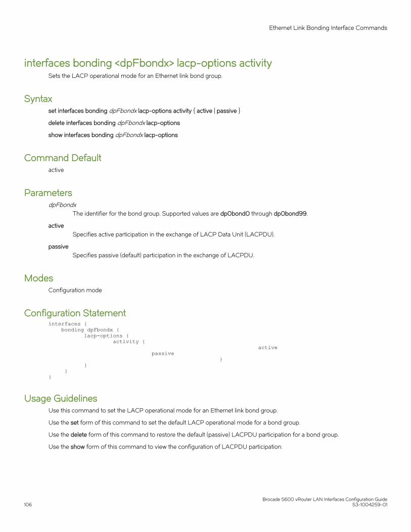
interfaces bonding <dpFbondx> lacp-options activitySets the LACP operational mode for an Ethernet link bond group.
Syntaxset interfaces bonding dpFbondx lacp-options activity { active | passive }
delete interfaces bonding dpFbondx lacp-options
show interfaces bonding dpFbondx lacp-options
Command Defaultactive
ParametersdpFbondx
The identifier for the bond group. Supported values are dp0bond0 through dp0bond99.
activeSpecifies active participation in the exchange of LACP Data Unit (LACPDU).
passiveSpecifies passive (default) participation in the exchange of LACPDU.
ModesConfiguration mode
Configuration Statementinterfaces { bonding dpFbondx { lacp-options { activity { active passive } } }}
Usage GuidelinesUse this command to set the LACP operational mode for an Ethernet link bond group.
Use the set form of this command to set the default LACP operational mode for a bond group.
Use the delete form of this command to restore the default (passive) LACPDU participation for a bond group.
Use the show form of this command to view the configuration of LACPDU participation.
Ethernet Link Bonding Interface Commands
Brocade 5600 vRouter LAN Interfaces Configuration Guide106 53-1004259-01

interfaces bonding <dpFbondx> lacp-options keySets the LACP aggregation (operational) key for an Ethernet link bond group.
Syntaxset interfaces bonding dpFbondx lacp-options key value
delete interfaces bonding dpFbondx lacp-options key
show interfaces bonding dpFbondx lacp-options key
Command Defaultactive
ParametersdpFbondx
The identifier for the bond group. Supported values are dp0bond0 through dp0bond99.
valueSpecifies an LACP aggregation (operational) key.
ModesConfiguration mode
Configuration Statementinterfaces { bonding dpFbondx { lacp-options { key value } } }
Usage GuidelinesUse this command to set the LACP aggregation (operational) key for an Ethernet link bond group.
Use the set form of this command to set is used to set the LACP aggregation (operational) key.
Use the delete form of this command is used to restore the LACP aggregation (operational) key.
Use the show form of this command to view the LACP aggregation (operational) key setting.
Ethernet Link Bonding Interface Commands
Brocade 5600 vRouter LAN Interfaces Configuration Guide53-1004259-01 107
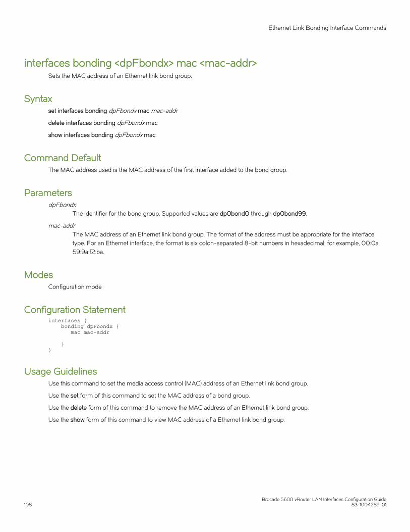
interfaces bonding <dpFbondx> mac <mac-addr>Sets the MAC address of an Ethernet link bond group.
Syntaxset interfaces bonding dpFbondx mac mac-addr
delete interfaces bonding dpFbondx mac
show interfaces bonding dpFbondx mac
Command DefaultThe MAC address used is the MAC address of the first interface added to the bond group.
ParametersdpFbondx
The identifier for the bond group. Supported values are dp0bond0 through dp0bond99.
mac-addrThe MAC address of an Ethernet link bond group. The format of the address must be appropriate for the interfacetype. For an Ethernet interface, the format is six colon-separated 8-bit numbers in hexadecimal; for example, 00:0a:59:9a:f2:ba.
ModesConfiguration mode
Configuration Statementinterfaces { bonding dpFbondx { mac mac-addr }}
Usage GuidelinesUse this command to set the media access control (MAC) address of an Ethernet link bond group.
Use the set form of this command to set the MAC address of a bond group.
Use the delete form of this command to remove the MAC address of an Ethernet link bond group.
Use the show form of this command to view MAC address of a Ethernet link bond group.
Ethernet Link Bonding Interface Commands
Brocade 5600 vRouter LAN Interfaces Configuration Guide108 53-1004259-01
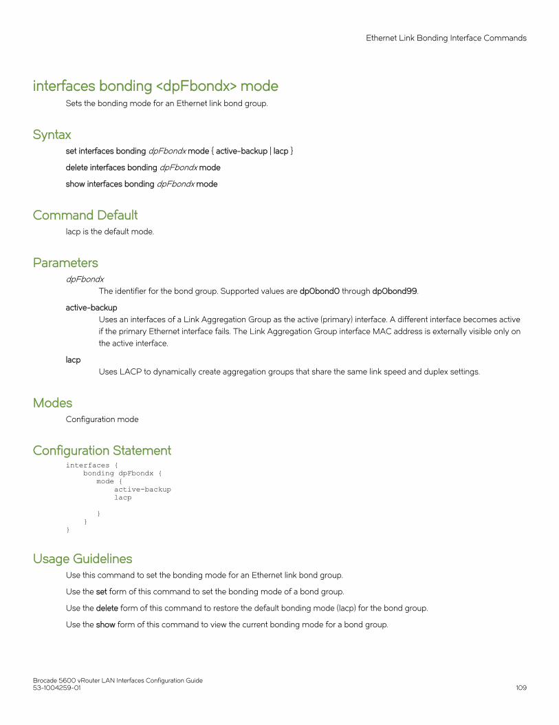
interfaces bonding <dpFbondx> modeSets the bonding mode for an Ethernet link bond group.
Syntaxset interfaces bonding dpFbondx mode { active-backup | lacp }
delete interfaces bonding dpFbondx mode
show interfaces bonding dpFbondx mode
Command Defaultlacp is the default mode.
ParametersdpFbondx
The identifier for the bond group. Supported values are dp0bond0 through dp0bond99.
active-backupUses an interfaces of a Link Aggregation Group as the active (primary) interface. A different interface becomes activeif the primary Ethernet interface fails. The Link Aggregation Group interface MAC address is externally visible only onthe active interface.
lacpUses LACP to dynamically create aggregation groups that share the same link speed and duplex settings.
ModesConfiguration mode
Configuration Statementinterfaces { bonding dpFbondx { mode { active-backup lacp } }}
Usage GuidelinesUse this command to set the bonding mode for an Ethernet link bond group.
Use the set form of this command to set the bonding mode of a bond group.
Use the delete form of this command to restore the default bonding mode (lacp) for the bond group.
Use the show form of this command to view the current bonding mode for a bond group.
Ethernet Link Bonding Interface Commands
Brocade 5600 vRouter LAN Interfaces Configuration Guide53-1004259-01 109
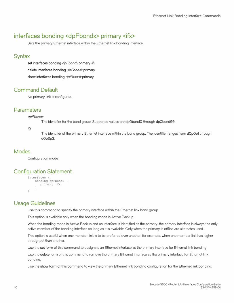
interfaces bonding <dpFbondx> primary <ifx>Sets the primary Ethernet interface within the Ethernet link bonding interface.
Syntaxset interfaces bonding dpFbondx primary ifx
delete interfaces bonding dpFbondx primary
show interfaces bonding dpFbondx primary
Command DefaultNo primary link is configured.
ParametersdpFbondx
The identifier for the bond group. Supported values are dp0bond0 through dp0bond99.
ifxThe identifier of the primary Ethernet interface within the bond group. The identifier ranges from d0p0p1 throughd0p2p3.
ModesConfiguration mode
Configuration Statementinterfaces { bonding dpFbondx { primary ifx }}
Usage GuidelinesUse this command to specify the primary interface within the Ethernet link bond group
This option is available only when the bonding mode is Active Backup.
When the bonding mode is Active Backup and an interface is identified as the primary, the primary interface is always the onlyactive member of the bonding interface so long as it is available. Only when the primary is offline are alternates used.
This option is useful when one member link is to be preferred over another; for example, when one member link has higherthroughput than another.
Use the set form of this command to designate an Ethernet interface as the primary interface for Ethernet link bonding.
Use the delete form of this command to remove the primary Ethernet interface as the primary interface for Ethernet linkbonding.
Use the show form of this command to view the primary Ethernet link bonding configuration for the Ethernet link bonding.
Ethernet Link Bonding Interface Commands
Brocade 5600 vRouter LAN Interfaces Configuration Guide110 53-1004259-01
show interfaces bondingShows information about Ethernet link bond groups
Syntaxshow interfaces bonding dpFbondx brief
show interfaces bonding dpFbondx slaves
show interfaces bonding dpFbondx [ vif value ]
Command DefaultInformation is displayed for all Ethernet link bond groups.
ParametersdpFbondx
The identifier for the bond group. Supported values are dp0bond0 through dp0bond99.
briefDisplays information about the bonding slaves.
slavesDisplays information about the bonding slaves in brief format.
ModesOperational mode
Usage GuidelinesUse this command to show bond group information.
Ethernet Link Bonding Interface Commands
Brocade 5600 vRouter LAN Interfaces Configuration Guide53-1004259-01 111
ExamplesThe following example shows the output for show interfaces bonding for all bonding interfaces.
vyatta@vyatta:~$ show interfaces bonding Codes: S - State, L - Link, u - Up, D - Down, A - Admin Down Interface IP Address S/L Description --------- ---------- --- ----------- dp0bond0 10.2.0.1/30 u/u dp0bond0.200 10.200.0.1/24 u/u
The following example shows the output for a specific bond group.
vyatta@vyatta:~$ show interfaces bonding dp0bond0 <BROADCAST,MULTICAST,UP,LOWER_UP> mtu 1500 qdisc pfifo_fast state UP group default qlen 500 link/ether 52:54:00:5a:b2:86 brd ff:ff:ff:ff:ff:ff inet 10.2.0.1/30 brd 10.2.0.3 scope global dp0bond0 valid_lft forever preferred_lft forever inet6 fe80::dc63:72ff:fe07:2c6/64 scope link valid_lft forever preferred_lft forever uptime: 45 seconds transitions: 1 last-change: 2015-04-09T18:31:45+0000 RX: bytes packets errors ignored overrun mcast 3126 27 0 0 0 0 TX: bytes packets errors dropped carrier collisions 3242 28 0 0 0 0
The following example shows the output for show interfaces bonding slaves.
vyatta@vyatta:~$ show interfaces bonding slaves Interface Mode State Link Slaves dp0bond0 802.3ad up up 2
The following example shows the output for show interfaces bonding dpFbondx slaves.
vyatta@vyatta:~$ show interfaces bonding dp0bond0 slavesInterface RX: bytes packets TX: bytes packets slctd LACP flags dp0bond0 15348 148 12184 129 dp0s5 3784 35 8976 98 yes DISTRIBUTINGdp0s6 11564 113 3208 31 yes DISTRIBUTING
The following example shows the output for show interfaces bonding dpFbondx vif value.
vyatta@vyatta:~$ show interfaces bonding dp0bond0 vif 200dp0bond0.200@dp0bond0: <BROADCAST,MULTICAST,UP,LOWER_UP> mtu 1500 qdisc noqueue state UP group default link/ether 52:54:00:5a:b2:86 brd ff:ff:ff:ff:ff:ffinet 10.200.0.1/24 brd 10.200.0.255 scope global dp0bond0.200 valid_lft forever preferred_lft foreverinet6 fe80::5054:ff:fe5a:b286/64 scope link valid_lft forever preferred_lft foreveruptime: 16 seconds transitions: 1 last-change: 2015-04-09T18:50:39+0000
RX: bytes packets errors ignored overrun mcast 1018 11 0 0 0 8TX: bytes packets errors dropped carrier collisions 1018 11 0 0 0 0
Related commands documented elsewhereThe following documents describe other system features that can be used with bonded Ethernet link interfaces.
Related Commands Documented Elsewhere
Bridging Layer 2 bridging is supported on bonding interfaces. Commands forconfiguring bridge groups are described in Brocade 5600 vRouterBridging Reference Guide.
Firewall Firewall is supported on bonding interfaces. Commands for configuringfirewall are described in Brocade 5600 vRouter Firewall Reference Guide.
Ethernet Link Bonding Interface Commands
Brocade 5600 vRouter LAN Interfaces Configuration Guide112 53-1004259-01
Related Commands Documented Elsewhere
OSPF OSPF is supported on bonding interfaces. Commands for configuringOSPF are described in Brocade 5600 vRouter OSPF Reference Guide.
OSPF OSPFv3 is supported on bonding interfaces. Commands for configuringOSPFv3 are described in Brocade 5600 vRouter OSPFv3 ReferenceGuide.
Policy Based Routing Policy-based routing is supported on bonding interfaces. Commands forconfiguring Policy-based routing are described in Brocade 5600 vRouterPolicy-based Routing Reference Guide.
RIP RIP is supported on bonding interfaces. Commands for configuring RIPare described in Brocade 5600 vRouter RIP Reference Guide.
RIPng RIPng is supported on bonding interfaces. Commands for configuringRIPng are described in Brocade 5600 vRouter RIPng Reference Guide.
Virtual interfaces 802.1Q VLAN operation is supported on bonding interfaces. Commandsfor configuring virtual interfaces (vifs) are described in Ethernet LinkBonding Interface on page 85.
VRRP VRRP is supported on bonding interfaces. Commands for configuringVRRP are described in Brocade 5600 vRouter High AvailabilityReference Guide.
Ethernet Link Bonding Interface Commands
Brocade 5600 vRouter LAN Interfaces Configuration Guide53-1004259-01 113

Ethernet Link Bonding Interface Commands
Brocade 5600 vRouter LAN Interfaces Configuration Guide114 53-1004259-01
VLAN Interfaces∙ VLAN interface overview.............................................................................................................................................................................................. 115∙ Examples of VLAN interface configuration........................................................................................................................................................ 116
VLAN interface overviewThis section presents the following topics:
∙ VLAN operation using virtual interfaces on page 115
∙ Interface types that support VLAN operation on page 115
∙ VLAN operation as opposed to multinetting on page 115
∙ Simultaneous Ethernet and 802.1q operation on page 115
∙ Referring to VLAN interfaces in commands on page 116
∙ IPv6 support on page 116
VLAN operation using virtual interfacesSome interface types can be configured for IEEE 802.1Q VLAN operation by using a virtual interface. On the Brocade vRouter, virtualinterfaces for VLANs are called vifs. As the identifier of a vif, you specify the VLAN to which the vif is connected.
Each physical interface can be configured with multiple vifs. Then, like a physical Ethernet interface, each vif can have multiple addressesassigned to it.
Interface types that support VLAN operationVLAN interfaces can be configured on physical Ethernet interfaces.
VLAN operation as opposed to multinettingVLANs are identified by a four-byte tag that is inserted at the front of the Layer 2 Ethernet header. Having this additional tag means thatinterfaces configured for 802.1Q are not compatible with standard Ethernet packets. When considering whether or not to use a VLANinterface, keep the following in mind.
∙ If you are using 802.1Q VLANs, create vif configuration nodes beneath the physical interface and assign the IP address to thevif.
∙ If you are not using 802.1Q but want to have multiple networks on the same physical interface (that is, you want to usemultinetting but not VLANs), simply create multiple address configuration nodes directly under the physical interface withoutusing vifs.
Simultaneous Ethernet and 802.1q operationIf your other network devices support it, an Ethernet interface may be used simultaneously as a standard port and an 802.1Q VLAN port.To do this, configure an IP address directly on the physical interface and then define a vif for the interface. Assign the VLAN ID as the vifidentifier and configure an IP address for the vif. (This feature may not be compatible with all Ethernet switches; some switches require aphysical Ethernet interface to be exclusively either an 802.1Q interface or a standard Ethernet interface.)
Brocade 5600 vRouter LAN Interfaces Configuration Guide53-1004259-01 115
Referring to VLAN interfaces in commandsTo refer to a vif within an interfaces command, such as show interfaces or set interfaces, specify the whole path to the vif configurationnode, as in the following example.
show interfaces dataplane dp0p1p2 vif 40
When referring to the same vif within other commands—for example, enabling RIP on the interface—use the format of if-x.vlan-id, whereif-x is the interface type plus the interface identifier (for example, dp0p1p2) and vlan-id is the VLAN ID (and also the identifier of the vif).The following example refers to the vif on VLAN 40 configured under the dp0p1p2 interface.
set protocols rip interface dp0p1p2.40
IPv6 supportThe Brocade vRouter has extensive support for IPv6, including IPv6 interface addressing. This chapter describes the commands forconfiguring IPv6 on VLAN interfaces. Brocade 5600 vRouter IPv6 Support Reference Guide fully describes Brocade vRouter IPv6support.
Examples of VLAN interface configurationThis section presents the following topics:
∙ VLAN configuration on page 116
∙ IPv6 on VLAN interfaces on page 117
VLAN configurationThis example shows how to configure the R1 router to have a vif for VLAN 40 on the dp0p1p2 Ethernet interface. After configuring thisVLAN, the R1 router has the following interfaces:
∙ One interface (dp0p1p1) that is configured as only a standard Ethernet interface. The IP address for this interface is 172.16.0.65.
∙ One interface (dp0p1p2) that is configured as both a physical Ethernet interface and a VLAN interface. The IP address for thephysical Ethernet interface is 10.10.30.65. The VLAN interface connects to VLAN 40 (the identifier of the vif) and has an IPaddress of 10.10.40.65.
NOTEBy default, the VLAN tag is the same as the vif. Only if vlan-id is defined does it override the tag value.
When you finish the example, the interfaces are configured as shown in the following figure.
VLAN Interfaces
Brocade 5600 vRouter LAN Interfaces Configuration Guide116 53-1004259-01
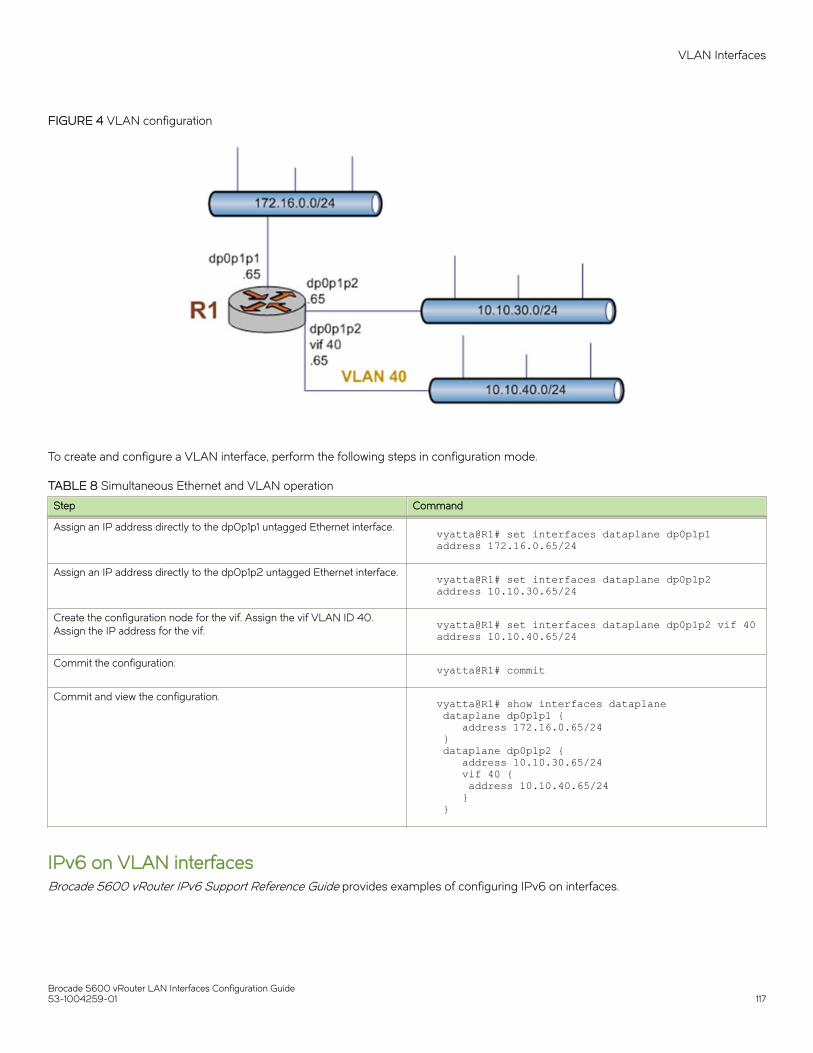
FIGURE 4 VLAN configuration
To create and configure a VLAN interface, perform the following steps in configuration mode.
TABLE 8 Simultaneous Ethernet and VLAN operation
Step Command
Assign an IP address directly to the dp0p1p1 untagged Ethernet interface. vyatta@R1# set interfaces dataplane dp0p1p1 address 172.16.0.65/24
Assign an IP address directly to the dp0p1p2 untagged Ethernet interface. vyatta@R1# set interfaces dataplane dp0p1p2 address 10.10.30.65/24
Create the configuration node for the vif. Assign the vif VLAN ID 40.Assign the IP address for the vif.
vyatta@R1# set interfaces dataplane dp0p1p2 vif 40 address 10.10.40.65/24
Commit the configuration. vyatta@R1# commit
Commit and view the configuration. vyatta@R1# show interfaces dataplane dataplane dp0p1p1 { address 172.16.0.65/24 } dataplane dp0p1p2 { address 10.10.30.65/24 vif 40 { address 10.10.40.65/24 } }
IPv6 on VLAN interfacesBrocade 5600 vRouter IPv6 Support Reference Guide provides examples of configuring IPv6 on interfaces.
VLAN Interfaces
Brocade 5600 vRouter LAN Interfaces Configuration Guide53-1004259-01 117

VLAN Interfaces
Brocade 5600 vRouter LAN Interfaces Configuration Guide118 53-1004259-01
VLAN Interfaces Commands∙ interfaces dataplane <interface-name> vif <vif-id>....................................................................................................................................... 120∙ interfaces dataplane <interface-name> vif <vif-id> address...................................................................................................................... 121∙ interfaces dataplane <interface-name> vif <vif-id> bridge-group........................................................................................................ 123∙ interfaces dataplane <interface-name> vif <vif-id> description <description>............................................................................... 125∙ interfaces dataplane <interface-name> vif <vif-id> dhcpv6-options.................................................................................................. 126∙ interfaces dataplane <interface-name> vif <vif-id> disable...................................................................................................................... 128∙ interfaces dataplane <interface-name> vif <vif-id> disable-link-detect............................................................................................ 129∙ interfaces dataplane <interface-name> vif <vif-id> ip disable-forwarding...................................................................................... 130∙ interfaces dataplane <interface-name> vif <vif-id> ip enable-proxy-arp........................................................................................... 131∙ interfaces dataplane <interface-name> vif <vif-id> ip rip receive..........................................................................................................132∙ interfaces dataplane <interface-name> vif <vif-id> ip rip send...............................................................................................................133∙ interfaces dataplane <interface-name> vif <vif-id> ip rpf-check........................................................................................................... 134∙ interfaces dataplane <interface-name> vif <vif-id> ipv6 address......................................................................................................... 135∙ interfaces dataplane <interface-name> vif <vif-id> ipv6 disable-forwarding..................................................................................137∙ interfaces dataplane <interface-name> vif <vif-id> ipv6 dup-addr-detect-transmits <num>.............................................. 138∙ interfaces dataplane <interface-name> vif <vif-id> ipv6 mld.................................................................................................................. 140∙ interfaces dataplane <interface-name> vif <vif-id> ipv6 ospfv3........................................................................................................... 142∙ interfaces dataplane <interface-name> vif <vif-id> ipv6 pim.................................................................................................................. 143∙ interfaces dataplane <interface-name> vif <vif-id> ipv6 router-advert............................................................................................. 144∙ interfaces dataplane <interface-name> vif <vif-id> ipv6 unnumbered donor-interface <interface>
preferred-address <ipv6-address>........................................................................................................................................................................148∙ interfaces dataplane <interface-name> vif <vif-id> mtu <mtu>.............................................................................................................. 149∙ interfaces dataplane <interface-name> vif <vif-id> vlan <vlan-id>......................................................................................................... 151∙ show interfaces dataplane <interface-name> vif <vif-id>.......................................................................................................................... 152∙ Related commands documented elsewhere................................................................................................................................................... 152
Brocade 5600 vRouter LAN Interfaces Configuration Guide53-1004259-01 119
interfaces dataplane <interface-name> vif <vif-id>Assigns a vif ID.
Syntaxset interfaces dataplane interface-name vif vif-id
delete interfaces dataplane interface-name vif vif-id
show interfaces dataplane interface-name vif vif-id
Parametersinterface-name
The name of a data plane interface. For more information about the supported interface name formats, refer to DataPlane Interface on page 215.
vif-idMultinode. The ID of a vif. The ID ranges from 1 through 4094.
ModesConfiguration mode
Configuration Statementinterfaces { dataplane interface-name { vif vif-id }}
Usage GuidelinesUse the set form of this command to assign an IP address and a network prefix to a vif.
Use the delete form of this command to delete a vif ID.
Use the show form of this command to display vif information.
VLAN Interfaces Commands
Brocade 5600 vRouter LAN Interfaces Configuration Guide120 53-1004259-01
interfaces dataplane <interface-name> vif <vif-id> addressAssigns an IP address and a network prefix to a vif.
Syntaxset interfaces dataplane interface-name vif vif-id address { ipv4 | ipv6 | dhcp | dhcpv6 }
delete interfaces dataplane interface-name vif vif-id address { ipv4 | ipv6 | dhcp | dhcpv6 }
show interfaces dataplane interface-name vif vif-id address
Parametersinterface-name
The name of a data plane interface. For more information about the supported interface name formats, refer to DataPlane Interface on page 215.
vif-idMultinode. The ID of a vif. The ID ranges from 1 through 4094.
ipv4An IPv4 address and a network prefix for this vif. The format is ip-address/prefix (for example, 192.168.1.77/24).You can define multiple IP addresses for a vif by creating multiple address configuration nodes.
ipv6An IPv6 address and a network prefix for this vif. The format is ipv6-address/prefix (for example, 2001:db8:1234::/48).You can define multiple IPv6 addresses for a vif by creating multiple address configuration nodes.
dhcpDefines the interface as a DHCP client, which obtains its address and prefix from a DHCP server.
dhcpv6Defines the interface as a DHCP for IPv6 client, which obtains its address and prefix from a DHCPv6 server.
ModesConfiguration mode
Configuration Statementinterfaces { dataplane interface-name { vif vif-id { address [ipv4 | ipv6 | dhcp | dhcpv6] } }}
Usage GuidelinesUse this command to assign an IP address and a network prefix to a vif.
Use the set form of this command to assign an IP address and a network prefix to a vif.
Use the delete form of this command to delete an IP address and a network prefix on a vif.
VLAN Interfaces Commands
Brocade 5600 vRouter LAN Interfaces Configuration Guide53-1004259-01 121

Use the show form of this command to display an IP address and a network prefix for a vif.
VLAN Interfaces Commands
Brocade 5600 vRouter LAN Interfaces Configuration Guide122 53-1004259-01
interfaces dataplane <interface-name> vif <vif-id> bridge-groupAdds a vif to a bridge group.
Syntaxset interfaces dataplane interface-name vif vif-id bridge-group { bridge bridge-group-name | cost port-cost | priority port-
priority | bpdu-guard | root-block }
delete interfaces dataplane interface-name vif vif-id bridge-group [ bridge | cost | priority ]
show interfaces dataplane interface-name vif vif-id bridge-group [ bridge | cost | priority ]
Parametersinterface-name
The name of a data plane interface. For more information about the supported interface name formats, refer to DataPlane Interface on page 215.
vif-idMultinode. The ID of a vif. The ID ranges from 1 through 4094.
bpdu-guardEnables Spanning Tree Protocol PortFast Bridge Protocol Data Unit (BPDU) guard.
bridge bridge-group-nameSpecifies the name of the bridge group.
cost port-costSpecifies the numeric port cost. The range is 0 to 65535.
priority port-prioritySpecifies the bridge port cost. The range is 0 to 63.
root-blockEnables Spanning Tree Protocol root guard.
ModesConfiguration mode
Configuration Statementinterfaces { dataplane interface-name { vif vif-id { bridge-group bpdu-guard bridge bridge-group-name cost port-cost priority port-priority root-block } }}
VLAN Interfaces Commands
Brocade 5600 vRouter LAN Interfaces Configuration Guide53-1004259-01 123

Usage GuidelinesUse this command to add a vif to a bridge group.
Use the set form of this command to add a vif to a bridge group.
Use the delete form of this command to delete a vif from a bridge group.
Use the show form of this command to display a vif of a bridge group.
VLAN Interfaces Commands
Brocade 5600 vRouter LAN Interfaces Configuration Guide124 53-1004259-01
interfaces dataplane <interface-name> vif <vif-id> description <description>Describes a description for a vif.
Syntaxset interfaces dataplane interface-name vif vif-id description description
delete interfaces dataplane interface-name vif vif-id description
show interfaces dataplane interface-name vif vif-id description
Parametersinterface-name
The name of a data plane interface. For more information about the supported interface name formats, refer to DataPlane Interface on page 215.
vif-idThe ID of a vif. The ID ranges from 1 through 4094.
descriptionA description of the vif.
ModesConfiguration mode
Configuration Statementinterfaces { dataplane interface-name { vif vif-id { description description } }}
Usage GuidelinesUse this command to describe a vif.
Use the set form of this command to describe a vif.
Use the delete form of this command to delete the description of a vif.
Use the show form of this command to display the description of a vif.
VLAN Interfaces Commands
Brocade 5600 vRouter LAN Interfaces Configuration Guide53-1004259-01 125
interfaces dataplane <interface-name> vif <vif-id> dhcpv6-optionsSpecifies the way in which a DHCPv6 client is to acquire an address, parameters, or both from the DHCPv6 server.
Syntaxset interfaces dataplane interface-name vif vif-id dhcpv6-options [ parameters-only | temporary ]
delete interfaces dataplane interface-name vif vif-id dhcpv6-options [ parameters-only | temporary ]
show interfaces dataplane interface-name vif vif-id dhcpv6-options
Parametersinterface-name
The name of a data plane interface. For more information about the supported interface name formats, refer to DataPlane Interface on page 215.
vif-idThe ID of a vif. The ID ranges from 1 through 4094.
parameters-onlyAcquires only configuration parameters (and not an IPv6 address) from the DHCPv6 server.Only one of the parameters-only and the temporary parameters can be specified.
temporaryAcquires a temporary IPv6 address as described for IPv6 privacy addressing in RFC 4941.Only one of the parameters-only and the temporary parameters can be specified.
ModesConfiguration mode
Configuration Statementinterfaces { dataplane interface-name { vif vif-id { dhcpv6-options [parameters-only | temporary] } }}
Usage GuidelinesUse this command to specify in what way the DHCPv6 client is to acquire an IPv6 address, parameters, or both from aDHCPv6 server.
Note that the parameters are relevant only if the dhcpv6 option has been set for interfaces dataplane <interface-name> vif <vif-id> on page 120.
The parameters-only parameter is typically used with Stateless Address Autoconfiguration (SLAAC) or static addressconfiguration. The parameters-only and temporary parameters are mutually exclusive.
Use the set form of this command to specify the DHCPv6 options for a vif.
VLAN Interfaces Commands
Brocade 5600 vRouter LAN Interfaces Configuration Guide126 53-1004259-01

Use the delete form of this command to remove the DHCPv6 options from a vif.
Use the show form of this command to view DHCPv6 option configuration of a vif.
VLAN Interfaces Commands
Brocade 5600 vRouter LAN Interfaces Configuration Guide53-1004259-01 127
interfaces dataplane <interface-name> vif <vif-id> disableDisables a vif without discarding configuration.
Syntaxset interfaces dataplane interface-name vif vif-id disable
delete interfaces dataplane interface-name vif vif-id disable
show interfaces dataplane interface-name vif vif-id
Command DefaultThe vif is enabled.
Parametersinterface-name
The name of a data plane interface. For more information about the supported interface name formats, refer to DataPlane Interface on page 215.
vif-idThe ID of a vif. The ID ranges from 1 through 4094.
ModesConfiguration mode
Configuration Statementinterfaces { dataplane interface-name { vif vif-id { disable } }}
Usage GuidelinesUse this command to disable a vif without discarding configuration for a vif.
Use the set form of this command to disable a vif.
Use the delete form of this command to enable a vif.
Use the show form of this command to display whether a vif is disabled or enabled.
VLAN Interfaces Commands
Brocade 5600 vRouter LAN Interfaces Configuration Guide128 53-1004259-01
interfaces dataplane <interface-name> vif <vif-id> disable-link-detectDirects a vif not to detect physical link-state changes.
Syntaxset interfaces dataplane interface-name vif vif-id disable-link-detect
delete interfaces dataplane interface-name vif vif-id disable-link-detect
show interfaces dataplane interface-name vif vif-id
Command DefaultA vif detects physical link-state changes.
Parametersinterface-name
The name of a data plane interface. For more information about the supported interface name formats, refer to DataPlane Interface on page 215.
vif-idThe ID of a vif. The ID ranges from 1 through 4094.
ModesConfiguration mode
Configuration Statementinterfaces { dataplane interface-name { vif vif-id { disable-link-detect } }}
Usage GuidelinesUse this command to direct a vif not to detect physical state change to the underlying Data plane link (for example, when acable is unplugged).
Use the set form of this command to disable detection of physical link-state changes for a vif.
Use the delete form of this command to enable detection of physical link-state changes for a vif.
Use the show form of this command to display whether detection of physical link-state changes is disabled or enabled on a vif.
VLAN Interfaces Commands
Brocade 5600 vRouter LAN Interfaces Configuration Guide53-1004259-01 129
interfaces dataplane <interface-name> vif <vif-id> ip disable-forwardingDisables IPv4 forwarding on a vif.
Syntaxset interfaces dataplane interface-name vif vif-id ip disable-forwarding
delete interfaces dataplane interface-name vif vif-id ip disable-forwarding
show interfaces dataplane interface-name vif vif-id ip disable-forwarding
Command DefaultIPv4 packets are forwarded.
Parametersinterface-name
The name of a data plane interface. For more information about the supported interface name formats, refer to DataPlane Interface on page 215.
vif-idThe ID of a vif. The ID ranges from 1 through 4094.
ModesConfiguration mode
Configuration Statementinterfaces { dataplane interface-name { vif vif-id { ip { disable-forwarding } } }}
Usage GuidelinesUse this command to disable IPv4 packet forwarding on a vif.
You can also disable IPv4 forwarding globally (that is, for all interfaces) by using the system ipv4 disable-forwarding command.
Use the set form of this command to disable IPv4 packet forwarding on a vif.
Use the delete form of this command to enable IPv4 packet forwarding on a vif.
Use the show form of this command to display whether IPv4 packet forwarding is disabled or enabled on a vif.
VLAN Interfaces Commands
Brocade 5600 vRouter LAN Interfaces Configuration Guide130 53-1004259-01
interfaces dataplane <interface-name> vif <vif-id> ip enable-proxy-arpEnables proxy ARP on a vif.
Syntaxset interfaces dataplane interface-name vif vif-id ip enable-proxy-arp
delete interfaces dataplane interface-name vif vif-id ip enable-proxy-arp
show interfaces dataplane interface-name vif vif-id ip enable-proxy-arp
Command DefaultProxy ARP is not enabled on the vif.
Parametersinterface-name
The name of a data plane interface. For more information about the supported interface name formats, refer to DataPlane Interface on page 215.
vif-idThe ID of a vif. The ID ranges from 1 through 4094.
ModesConfiguration mode
Configuration Statementinterfaces { dataplane interface-name { vif vif-id { ip { enable-proxy-arp } } }}
Usage GuidelinesUse this command to enable proxy Address Resolution Protocol (ARP) on a vif.
Proxy ARP allows a data plane interface to respond with its own media access control (MAC) address to ARP requests fordestination IP addresses on subnets that are attached to other interfaces on the system. Subsequent packets sent to thosedestination IP addresses are forwarded appropriately by the system.
Use the set form of this command to enable proxy ARP on a vif.
Use the delete form of this command to return the system to its default behavior, that is, proxy ARP is not enabled on a dataplane interface.
Use the show form of this command to display whether IPv4 packet forwarding is disabled or enabled on a vif.
VLAN Interfaces Commands
Brocade 5600 vRouter LAN Interfaces Configuration Guide53-1004259-01 131
interfaces dataplane <interface-name> vif <vif-id> ip rip receiveConfigures receive options for RIP packets on a vif.
Syntaxset interfaces dataplane interface-name vif vif-id ip rip receive [ version version ]
delete interfaces dataplane interface-name vif vif-id ip rip receive
show interfaces dataplane interface-name vif vif-id ip rip receive
Parametersinterface-name
The name of a data plane interface. For more information about the supported interface name formats, refer to DataPlane Interface on page 215.
vif-idThe ID of a vif. The ID ranges from 1 through 4094.
versionSpecifies a version of RIP packets. Legal values are 1, 2, or both.
ModesConfiguration mode
Configuration Statementinterfaces { dataplane interface-name { vif vif-id { ip { rip { receive [version version] } } } }}
Usage GuidelinesUse this command to configure receive options for RIP packets on a vif.
Use the set form of this command to configure the receive options for a vif, including an optional version.
Use the delete form of this command to restore the default configuration for a vif.
Use the show form of this command to display the configuration for a vif.
VLAN Interfaces Commands
Brocade 5600 vRouter LAN Interfaces Configuration Guide132 53-1004259-01
interfaces dataplane <interface-name> vif <vif-id> ip rip sendConfigures send options for RIP packets on a vif.
Syntaxset interfaces dataplane interface-name vif vif-id ip rip send [ version version ]
delete interfaces dataplane interface-name vif vif-id ip rip send
show interfaces dataplane interface-name vif vif-id ip rip send
Parametersinterface-name
The name of a data plane interface. For more information about the supported interface name formats, refer to DataPlane Interface on page 215.
vif-idThe ID of a vif. The ID ranges from 1 through 4094.
versionSpecifies a version of RIP packets. Legal values are 1, 2, or both.
ModesConfiguration mode
Configuration Statementinterfaces { dataplane interface-name { vif vif-id { ip { rip { send [version version] } } } }}
Usage GuidelinesUse this command to configure send options for RIP packets on a vif.
Use the set form of this command to configure the send options for a vif, including an optional version.
Use the delete form of this command to restore the default configuration for a vif.
Use the show form of this command to display the configuration for a vif.
VLAN Interfaces Commands
Brocade 5600 vRouter LAN Interfaces Configuration Guide53-1004259-01 133
interfaces dataplane <interface-name> vif <vif-id> ip rpf-checkSpecifies reverse path filter (RPF) policy (see RFC3704).
Syntaxset interfaces dataplane interface-name vif vif-id ip rip rpf-check { disable | loose | strict }
delete interfaces dataplane interface-name vif vif-id ip rip rpf-check
show interfaces dataplane interface-name vif vif-id ip rip rpf-check
Parametersinterface-name
The name of a data plane interface. For more information about the supported interface name formats, refer to DataPlane Interface on page 215.
vif-idThe ID of a vif. The ID ranges from 1 through 4094.
disableDoes not validate the source.
looseEnables Loose Reverse Path Forwarding as defined in RFC3704
strictEnable Strict Reverse Path Forwarding as defined in RFC3704.
ModesConfiguration mode
Configuration Statementinterfaces { dataplane interface-name { vif vif-id { ip { rpf-check {disable | loose | strict} } } }}
Usage GuidelinesUse this command to specify reverse path filter (RPF) policy for a vif (see RFC3704).
Use the set form of this command to configure the policy for a vif.
Use the delete form of this command to restore the default configuration of a vif.
Use the show form of this command to display the configuration of a vif.
VLAN Interfaces Commands
Brocade 5600 vRouter LAN Interfaces Configuration Guide134 53-1004259-01
interfaces dataplane <interface-name> vif <vif-id> ipv6 addressAssigns an IPv6 address to a vif.
Syntaxset interfaces dataplane interface-name vif vif-id ipv6 address [ autoconf | eui64 ipv6prefix | link-local ipv6-address ]
delete interfaces dataplane interface-name vif vif-id ipv6 address [ autoconf | eui64 ipv6prefix | link-local ]
show interfaces dataplane interface-name vif vif-id ipv6 address
Parametersinterface-name
The name of a data plane interface. For more information about the supported interface name formats, refer to DataPlane Interface on page 215.
vif-idThe ID of a vif. The ID ranges from 1 through 4094.
autoconfGenerates an IPv6 address using the SLAAC protocol. Use this keyword if the interface is performing a “host” functionrather than a “router” function. You can specify this keyword in addition to static IPv6, static IPv4, or IPv4 DHCPaddresses on the vif.
eui64 ipv6prefixSpecifies the 64-bit IPv6 address prefix that is used to configure an IPv6 address, in EUI-64 format. The systemconcatenates this prefix with a 64-bit EUI-64 value that is derived from the 48-bit MAC address of the vif.
link-local ipv6-addressSpecifies the 128-bit IPv6 address.
ModesConfiguration mode
Configuration Statementinterfaces { dataplane interface-name { vif vif-id { ipv6 { address [autoconf | eui64 ipv6prefix | link-local ipv6-address] } } }}
Usage GuidelinesUse this command to assign an IPv6 address to a vif.
Use the autoconf keyword to direct the system to automatically configure (autoconfigure) the address, using the StatelessAddress Autoconfiguration (SLAAC) protocol defined in RFC 4862. Alternatively, you can provide an EUI-64 IPv6 addressprefix so that the system constructs the IPv6 address.
VLAN Interfaces Commands
Brocade 5600 vRouter LAN Interfaces Configuration Guide53-1004259-01 135

If you want the system to use SLAAC to acquire addresses on the interface, then in addition to setting this parameter, you mustalso disable IPv6 forwarding, either globally (by using the system ipv6 disable-forwarding command) or specifically on theinterface (by using interfaces dataplane <interface-name> vif <vif-id> ipv6 disable-forwarding on page 137).
Use the set form of this command to assign an IPv6 address to a vif.
Use the delete form of this command to delete an IPv6 address from a vif.
Use the show form of this command to view IPv6 address configuration settings for a vif.
VLAN Interfaces Commands
Brocade 5600 vRouter LAN Interfaces Configuration Guide136 53-1004259-01
interfaces dataplane <interface-name> vif <vif-id> ipv6 disable-forwardingDisables IPv6 forwarding on a vif.
Syntaxset interfaces dataplane interface-name vif vif-id ipv6 disable-forwarding
delete interfaces dataplane interface-name vif vif-id ipv6 disable-forwarding
show interfaces dataplane interface-name vif vif-id ipv6 disable-forwarding
Command DefaultIPv6 packets are forwarded.
Parametersinterface-name
The name of a data plane interface. For more information about the supported interface name formats, refer to DataPlane Interface on page 215.
vif-idThe ID of a vif. The ID ranges from 1 through 4094.
ModesConfiguration mode
Configuration Statementinterfaces { dataplane interface-name { vif vif-id { ipv6 { disable-forwarding } } }}
Usage GuidelinesUse this command to disable IPv6 packet forwarding on a vif.
You can also disable IPv6 forwarding globally (that is, for all interfaces) by using the system ipv6 disable-forwarding command.
Use the set form of this command to disable IPv6 packet forwarding on a vif.
Use the delete form of this command to enable IPv6 packet forwarding on a vif.
Use the show form of this command to display whether IPv6 packet forwarding is disabled or enabled on a vif.
VLAN Interfaces Commands
Brocade 5600 vRouter LAN Interfaces Configuration Guide53-1004259-01 137
interfaces dataplane <interface-name> vif <vif-id> ipv6 dup-addr-detect-transmits <num>
Specifies the number of NS packets to transmit as part of the DAD process.
Syntaxset interfaces dataplane interface-name vif vif-id ipv6 dup-addr-detect-transmits num
delete interfaces dataplane interface-name vif vif-id ipv6 dup-addr-detect-transmits
show interfaces dataplane interface-name vif vif-id ipv6 dup-addr-detect-transmits
Command DefaultOne NS packet is transmitted as part of the DAD process.
Parametersinterface-name
The name of a data plane interface. For more information about the supported interface name formats, refer to DataPlane Interface on page 215.
vif-idThe ID of a vif. The ID ranges from 1 through 4094.
numThe number of NS messages to transmit as part of the DAD process. The number ranges from 1 through4294967295. The default number is 1.
ModesConfiguration mode
Configuration Statementinterfaces { dataplane interface-name { vif vif-id { ipv6 { dup-addr-detect-transmits num } } }}
Usage GuidelinesUse this command to specify the number of Neighbor Solicitation (NS) packets to transmit as part of the Duplicate AddressDetection (DAD) process on a vif.
Use the set form of this command to specify the number of NS packets to transmit on a vif.
Use the delete form of this command to delete the transmission number from a vif and transmit the default number of one NSpacket.
VLAN Interfaces Commands
Brocade 5600 vRouter LAN Interfaces Configuration Guide138 53-1004259-01

Use the show form of this command to display the number of NS packets to transmit on a vif.
VLAN Interfaces Commands
Brocade 5600 vRouter LAN Interfaces Configuration Guide53-1004259-01 139
interfaces dataplane <interface-name> vif <vif-id> ipv6 mldEnables MLD on an interface.
Syntaxset interfaces dataplane interface-name vif vif-id ipv6 mld
delete interfaces dataplane interface-name vif vif-id ipv6 mld
show interfaces dataplane interface-name vif vif-id ipv6 mld
Parametersinterface-name
The name of a data plane interface. For more information about the supported interface name formats, refer to DataPlane Interface on page 215.
vif-idThe ID of a vif. The ID ranges from 1 through 4094.
ModesConfiguration mode
Configuration Statementinterfaces { dataplane interface-name { vif vif-id { ipv6 { mld } } }}
Usage GuidelinesUse this command to enable Multicast Listener Discovery (MLD) on a vif.
This command enables MLD operation in stand-alone mode, and can be used to learn local membership information prior toenabling a multicast routing protocol on the vif.
This command can only be issued on VLAN interfaces.
NOTEEnabling IP on a vif enables the host-side functionality of MLD by default. The set interfaces dataplane interface-name vif vif-id ipv6 mld command enables the router-side functionality of the MLD on the given vif.
NOTETo use MLD for multicast routing, multicast routing must be enabled on the router. For information about multicastrouting in general, see the Brocade 5600 vRouter Multicast Routing Reference Guide.
Use the set form of this command to enable MLD on a vif.
VLAN Interfaces Commands
Brocade 5600 vRouter LAN Interfaces Configuration Guide140 53-1004259-01

Use the delete form of this command to remove all MLD configuration and disable MLD on a vif.
Use the show form of this command to display MLD configuration for a vif.
VLAN Interfaces Commands
Brocade 5600 vRouter LAN Interfaces Configuration Guide53-1004259-01 141
interfaces dataplane <interface-name> vif <vif-id> ipv6 ospfv3Enables OSPFv3 on a specified interface.
Syntaxset interfaces dataplane interface-name vif vif-id ipv6 ospfv3 [ process process-id [ instance-id instance-id ] ]
delete interfaces dataplane interface-name vif vif-id ipv6 ospfv3 [ [ process process-id instance-id instance-id ] ]
show interfaces dataplane interface-name vif vif-id ipv6 ospfv3 [ process process-id [ instance-id instance-id ] ]
Parametersinterface-name
The name of a data plane interface. For more information about the supported interface name formats, refer to DataPlane Interface on page 215.
vif-idThe ID of a vif. The ID ranges from 1 through 4094.
process-idThe OSPFv3 process ID. Enter alphanumeric characters.
instance-idThe OSPFv3 instance ID. The range is from 0 to 255.
ModesConfiguration mode
Configuration Statementinterfaces { dataplane interface-name { vif vif-id { ipv6 { ospfv3 [process process-id [instance-id instance-id]] } } }}
Usage GuidelinesUse this command to enable the OSPFv3 routing protocol on a vif.
Use the set form of this command to enable OSPFv3 on a vif.
Use the delete form of this command to remove all OSPFv3 configuration and disable OSPFv3 on a vif.
Use the show form of this command to display OSPFv3 configuration for a vif.
VLAN Interfaces Commands
Brocade 5600 vRouter LAN Interfaces Configuration Guide142 53-1004259-01
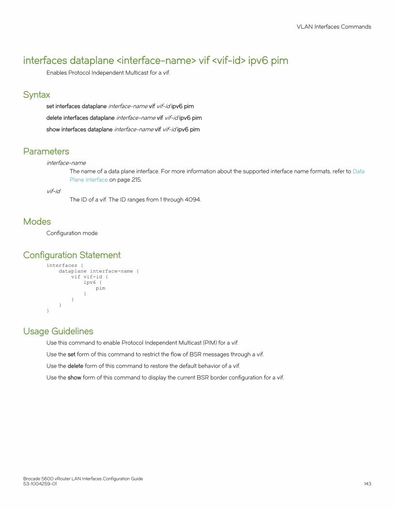
interfaces dataplane <interface-name> vif <vif-id> ipv6 pimEnables Protocol Independent Multicast for a vif.
Syntaxset interfaces dataplane interface-name vif vif-id ipv6 pim
delete interfaces dataplane interface-name vif vif-id ipv6 pim
show interfaces dataplane interface-name vif vif-id ipv6 pim
Parametersinterface-name
The name of a data plane interface. For more information about the supported interface name formats, refer to DataPlane Interface on page 215.
vif-idThe ID of a vif. The ID ranges from 1 through 4094.
ModesConfiguration mode
Configuration Statementinterfaces { dataplane interface-name { vif vif-id { ipv6 { pim } } }}
Usage GuidelinesUse this command to enable Protocol Independent Multicast (PIM) for a vif.
Use the set form of this command to restrict the flow of BSR messages through a vif.
Use the delete form of this command to restore the default behavior of a vif.
Use the show form of this command to display the current BSR border configuration for a vif.
VLAN Interfaces Commands
Brocade 5600 vRouter LAN Interfaces Configuration Guide53-1004259-01 143
interfaces dataplane <interface-name> vif <vif-id> ipv6 router-advertSpecifies the router advertisements to be sent from a vif.
Syntaxset interfaces dataplane interface-name vif vif-id ipv6 router-advert [ cur-hop-limit limit ] [ default-lifetime lifetime ] [ default-
preference preference ] [ link-mtu mtu ] [ managed-flag state ] [ max-interval interval ] [ min-interval interval ] [ other-config-flag state ] [ prefix ipv6net [ autonomous-flag state | on-link-flag state | preferred-lifetime lifetime | valid-lifetimelifetime ] ] [ reachable-time time ] [ retrans-timer time ] [ send-advert state ]
delete interfaces dataplane interface-name vif vif-id ipv6 router-advert [ cur-hop-limit ] [ default-lifetime ] [ default-preference ][ link-mtu ] [ managed-flag ] [ max-interval ] [ min-interval ] [ other-config-flag ] [ prefix ipv6net [ autonomous-flag | on-link-flag | preferred-lifetime | valid-lifetime ] ] [ reachable-time ] [ retrans-timer [ send-advert ]
show interfaces dataplane interface-name vif vif-id ipv6 router-advert
Command DefaultRouter advertisements are not sent on a vif.
Parametersinterface-name
The name of a data plane interface. For more information about the supported interface name formats, refer to DataPlane Interface on page 215.
vif-idThe ID of a vif. The ID ranges from 1 through 4094.
cur-hop-limit limitSpecifies the Hop Count field of the IP header for outgoing (unicast) IP packets. This value is placed in the Hop Countfield of the IP header for outgoing (unicast) IP packets. The range is 0 to 255. The default is 64. A limit of 0 meansunspecified by the router.
default-lifetime lifetimeSpecifies the lifetime, in seconds, that is associated with the default router. A lifetime of 0 indicates that the router isnot a default router. The lifetime ranges from the value configured for the max-interval option to 9000 (18.2 hours). Ifthe lifetime is not configured, the value for this timer is three times max-interval.
default-preference preferenceThe preference associated with the default router. Supported values are as follows:low: The default router is low preference.medium: The default router is medium preference.high: The default router is high preference.The default is medium.
link-mtu mtuSpecifies the MTU to be advertised for the link. The MTU is 0 or ranges from 1280 through the maximum MTU forthe type of link, as defined in RFC 2464. The default MTU is 0, which means the MTU is not specified in the routeradvertisement message. That is because it is expected that the MTU is configured directly on the interface itself andnot for routing advertisements. You can configure this option when the link MTU is not well known.
VLAN Interfaces Commands
Brocade 5600 vRouter LAN Interfaces Configuration Guide144 53-1004259-01
If the MTU that is set here does not match the MTU that is configured on the interface, the system issues a warningbut does not fail.
managed-flag stateWhether to use the administered protocol for address autoconfiguration. The state is either of the following:true: Hosts use the administered (stateful) protocol for address autoconfiguration in addition to any addressesautoconfigured using stateless address autoconfiguration.false: Hosts use only stateless address autoconfiguration.The default state is false.
max-interval intervalSpecifies the maximum time, in seconds, that is allowed between sending unsolicited multicast router advertisementsfrom the interface. The interval ranges from 4 through 1800. The default is 600 (10 minutes).
min-interval intervalSpecifies the minimum time, in seconds, that is allowed between sending unsolicited multicast router advertisementsfrom the interface. The interval ranges from 3 through 0.75 times the max-interval option. The default interval is 0.33times max-interval.
other-config-flag stateSpecifies that the interface use the administered (stateful) protocol for autoconfiguration of nonaddress information, asdefined in RFC 4862. The state is either of the following:true: Hosts use the administered protocol for autoconfiguration of nonaddress information.false: Hosts use stateless autoconfiguration of nonaddress information.The default state is false.
prefix ipv6netMultinode. Specifies the IPv6 prefix to be advertised on the IPv6 interface, in the format ipv6-address/prefix.You can define more than one IPv6 prefix by configuring multiple prefix configuration nodes.
autonomous-flag stateSpecifies whether the prefix can be used for autonomous address configuration as defined in RFC 4862. The state iseither of the following:true: The prefix can be used for autonomous address configuration.false: The prefix cannot be used for autonomous address configuration.The default state is true.
on-link-flag stateSpecifies whether the prefix can be used for onlink determination, as defined in RFC 4862. The state is either of thefollowing:true: The prefix can be used for onlink determination.false: The advertisement makes no statement about onlink or off-link properties of the prefix. For instance, the prefixmight be used for address configuration with some addresses belonging to the prefix being onlink and others beingoff-link.The default state is true.
preferred-lifetime lifetimeSpecifies the length of time, in seconds, that the addresses generated from the prefix by Stateless AddressAutoconfiguration (SLAAC) is to remain preferred, as defined in RFC 4862. The interval is with respect to the time thepacket is sent. The lifetime ranges from 1 through 4294967296 plus the infinity keyword, which represents forever.(The actual value of infinity is a byte in which all bits are set to 1s: 0XFFFFFFFF.) The default lifetime is 604800 (7days).
valid-lifetime lifetime
VLAN Interfaces Commands
Brocade 5600 vRouter LAN Interfaces Configuration Guide53-1004259-01 145

Specifies the length of time, in seconds, that the prefix is valid for onlink determination, as defined in RFC 4862. Theinterval is with respect to the time the packet is sent. The time ranges from 1 through 4294967296 plus the infinitykeyword, which represents forever. (The actual value of infinity is a byte in which all bits are set to 1s: 0XFFFFFFFF.)The default lifetime is 2592000 (30 days).
reachable-time timeSpecifies the length of time, in milliseconds, for which the system assumes a neighbor is reachable after havingreceived a reachability confirmation. This time is used by address resolution and the Neighbor UnreachabilityDetection algorithm (see Section 7.3 of RFC 2461). The time ranges from 0 through 3600000, where a value of 0means the reachable time is not specified in the router advertisement message. The default time is 0.
retrans-timer timeSpecifies the length of time, in milliseconds, between retransmitted NS messages. This time is used by addressresolution and the Neighbor Unreachability Detection algorithm (see Sections 7.2 and 7.3 of RFC 2461). The timeranges from 0 through 4294967295, where a value of 0 means the retransmit time is not specified in the routeradvertisement message. The default time is 0.
send-advert stateSpecifies whether router advertisements are to be sent from this interface. The state is either of the following:true: Sends router advertisements from this interface.false: Does not send router advertisements from this interface. If a state is in effect, parameters in this configurationsubtree are still used to configure the local implementation parameters.The default state is true.
ModesConfiguration mode
Configuration Statementinterfaces { dataplane interface-name { vif vif-id { ipv6 { router-advert { cur-hop-limit limit default-lifetime lifetime default-preference preference link-mtu mtu managed-flag state max-interval interval min-interval interval other-config-flag state prefix ipv6net { autonomous-flag state on-link-flag state preferred-lifetime lifetime valid-lifetime lifetime } reachable-time time retrans-timer time send-advert state } } } }}
VLAN Interfaces Commands
Brocade 5600 vRouter LAN Interfaces Configuration Guide146 53-1004259-01
Usage GuidelinesUse this command to specify the router advertisements to be sent from a vif.
Router advertisements are sent by IPv6 routers to advertise their existence to hosts on the network. IPv6 hosts do not sendrouter advertisements.
If the router-advert node of the configuration tree is missing, router advertisements are not sent. In addition, if IPv6 forwardingis disabled either globally (by using the system ipv6 disable-forwarding command) or on the interface (by using interfacesdataplane <interface-name> vif <vif-id> ipv6 disable-forwarding on page 137), router advertisements are not sent.
Most router advertisement parameters are required by either the Neighbor Discovery (ND) protocol or the Stateless AddressAutoconfiguration (SLAAC) protocol. These parameters are used both locally for the IPv6 implementation and become part ofthe RA messages sent to hosts on the network so that they can be configured appropriately.
Use the set form of this command to create the router-advert configuration node and begin to send router advertisements on avif.
Use the delete form of this command to delete router-advert configuration node and stop sending router advertisements on avif.
Use the show form of this command to view router advertisement configuration for a vif.
VLAN Interfaces Commands
Brocade 5600 vRouter LAN Interfaces Configuration Guide53-1004259-01 147
interfaces dataplane <interface-name> vif <vif-id> ipv6 unnumbered donor-interface <interface> preferred-address <ipv6-address>
Configures the vif of the specified data plane interfaces as an IP unnumbered interface with the donor interface and preferredaddress.
Syntaxset interfaces dataplane interface-name vif vif-id ipv6 unnumbered donor-interface interface preferred-address ipv6-address
delete interfaces dataplane interface-name vif vif-id ipv6 unnumbered
show interfaces dataplane interface-name vif vif-id ipv6 unnumbered
Parametersinterface-name
The name of a data plane interface. For more information about the supported interface name formats, refer to DataPlane Interface on page 215.
vif-idThe ID of a vif. The ID ranges from 1 through 4094.
interfaceSpecifies the interface.
ipv6-addressSpecifies the 128-bit IPv6 address of another interface.
ModesConfiguration mode
Configuration Statementinterfaces { dataplane interface-name { vif vif-id { ipv6 { unnumbered donor‐interface interface preferred-address ipv6-address } } }}
Usage GuidelinesConfigures IP processing on a vif with the requirement of an assigned IP address.
Use the set form of this command to configure the processing.
Use the delete form of this command to restore the default configuration.
Use the show form of this command to display the configuration.
VLAN Interfaces Commands
Brocade 5600 vRouter LAN Interfaces Configuration Guide148 53-1004259-01
interfaces dataplane <interface-name> vif <vif-id> mtu <mtu>Set the maximum transmission unit (MTU) for a vif.
Syntaxset interfaces dataplane interface-name vif vif-id mtu mtu
delete interfaces dataplane interface-name vif vif-id mtu
show interfaces dataplane interface-name vif vif-id mtu
Command DefaultThe default size of the MTU is 1500.
Parametersinterface-name
The name of a data plane interface. For more information about the supported interface name formats, refer to DataPlane Interface on page 215.
vif-idThe ID of a vif. The ID ranges from 1 through 4094.
mtuThe size of the MTU, in octets, for the vif as a whole. The size of the MTU ranges from 68 through 9000.
ModesConfiguration mode
Configuration Statementinterfaces { dataplane interface-name { vif vif-id { mtu mtu } }}
Usage GuidelinesUse this command to set the size of the maximum transmission unit (MTU) for a vif.
During forwarding, IPv4 packets larger than the MTU are fragmented unless the “Don't Fragment” (DF) bit is set in the IPheader. In that case, the packets are dropped and an ICMP “fragmentation needed” message is returned to the sender.
Note that MTU sizes larger than 1500 cause the system to generate “jumbo frames,” which are not compatible with some dataplane interface cards and devices.
If the data plane interface is part of an Ethernet link bond, MTU settings for the bonded link override MTU settings for thephysical interface.
Use the set form of this command to specify the size of the MTU.
VLAN Interfaces Commands
Brocade 5600 vRouter LAN Interfaces Configuration Guide53-1004259-01 149

Use the delete form of this command to delete the size of the MTU and restore the default size of 1500.
Use the show form of this command to display the current size of the MTU.
VLAN Interfaces Commands
Brocade 5600 vRouter LAN Interfaces Configuration Guide150 53-1004259-01
interfaces dataplane <interface-name> vif <vif-id> vlan <vlan-id>Creates a vif.
Syntaxset interfaces dataplane interface-name vif vif-id [ vlan vlan-id ]
delete interfaces dataplane interface-name vif vif-id [ vlan vlan-id ]
show interfaces dataplane interface-name vif vif-id [ vlan vlan-id ]
Parametersdataplane interface-name
The name of a data plane interface. For more information about the supported interface name formats, refer to DataPlane Interface on page 215.
vif vif-idMultinode. The ID of a vif. The ID ranges from 1 through 4094.
vlan vlan-idMultinode. The VLAN ID of a vif, for use with 802.1Q VLAN tagging. The ID ranges from 1 through 4094. Note thatonly 802.1Q-tagged packets are accepted on Ethernet vifs.You can define more than one vif for an interface by creating multiple vif configuration nodes.
ModesConfiguration mode
Configuration Statementinterfaces { dataplane interface-name { vif vif-id { vlan vlan-id } }}
Usage GuidelinesUse this command to create a vif. The vifs function as VLAN interfaces, and only 802.1Q tagged packets are accepted.
NOTEThe interface must be defined before a vif can be added.
Use the set form of this command to create a vif.
Use the delete form of this command to delete a vif.
Use the show form of this command to display a vif.
VLAN Interfaces Commands
Brocade 5600 vRouter LAN Interfaces Configuration Guide53-1004259-01 151
show interfaces dataplane <interface-name> vif <vif-id>Displays the operational status of a vif.
Syntaxshow interfaces dataplane interface-name vif vif-id [ brief ]
Parametersinterface-name
The name of a data plane interface. For more information about the supported interface name formats, refer to DataPlane Interface on page 215.
vif-idThe ID of a vif. The ID ranges from 1 through 4094.
briefDisplays a brief status of the vif.
ModesOperational mode
Usage GuidelinesUse this command to display the operational status of a vif.
Related commands documented elsewhereCommands for using other system features with VLAN interfaces are located in the following guides.
Related Commands Documented Elsewhere
IGMP and MLD IGMP and MLD are supported on IPv4 VLAN interfaces. Commands forconfiguring IGMP and MLD are described in the Brocade 5600 vRouterIGMP and MLD Reference Guide.
Multicast Multicast is supported on IPv4 VLAN interfaces. Commands forconfiguring multicast are described in the Brocade 5600 vRouterMulticast Routing Reference Guide.
OSPF OSPF is supported on IPv4 VLAN interfaces. Commands for configuringOSPF are described in the Brocade 5600 vRouter OSPF ReferenceGuide.
OSPFv3 OSPFv3 is supported on IPv4 VLAN interfaces. Commands forconfiguring OSPFv3 are described in the Brocade 5600 vRouterOSPFv3 Reference Guide.
PIM PIM is supported on IPv4 and IPv6 VLAN interfaces. Commands forconfiguring PIM are described in the Brocade 5600 vRouter PIMReference Guide.
RIP RIP is supported on IPv4 VLAN interfaces. Commands for configuringRIP are described in the Brocade 5600 vRouter RIP Reference Guide.
VLAN Interfaces Commands
Brocade 5600 vRouter LAN Interfaces Configuration Guide152 53-1004259-01
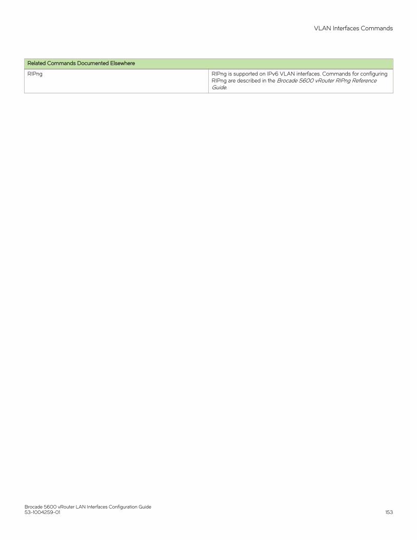
Related Commands Documented Elsewhere
RIPng RIPng is supported on IPv6 VLAN interfaces. Commands for configuringRIPng are described in the Brocade 5600 vRouter RIPng ReferenceGuide.
VLAN Interfaces Commands
Brocade 5600 vRouter LAN Interfaces Configuration Guide53-1004259-01 153

VLAN Interfaces Commands
Brocade 5600 vRouter LAN Interfaces Configuration Guide154 53-1004259-01
Q-in-Q Interface∙ Q-in-Q interface overview..........................................................................................................................................................................................155∙ Configuring the Q-in-Q interface........................................................................................................................................................................... 156
Q-in-Q interface overviewThis section presents the following topics:
∙ Q-in-Q interface features on page 155
∙ Packet processing using QoS schedulers on page 155
With services such as metro Ethernet, the demand for VLAN IDs can increase beyond the original space limit of 4K. Q-in-Q enables theVLAN ID space to be extended from 4K to 16M, while also reducing the number of VLANs that must be managed.
The Brocade 5600 vRouter Q-in-Q implementation is based on IEEE 802.1ad—multiple VLAN tags in an IP packet frame. The Q-in-Qinterface is able to insert two VLAN tags into the Ethernet frame of a packet.
The Q-in-Q interface is supported on the data plane interface and must be configured as a virtual interface (vif). You configure the innerVLAN and the outer VLAN by using the VIF CLI commands, modify the data plane to be able to process packets with two VLAN tags,and then display the VLAN IDs of the VIF interface.
Only the outer VLAN tag is used when scheduling QoS packets. The outer VLAN tag can use EtherTypes 0x8100, 0x9100, 0x9200,0x9300 and 0x88A8. The inner VLAN tag uses only 0x8100.
The outer VLAN is also referred to as “service VLAN” (S-VLAN) while the inner VLAN is called “customer VLAN” (C-VLAN).
When a Q-in-Q VIF is configured, two logical interfaces are created in the Linux kernel and the data plane—one representing the outerVLAN and the other representing the inner VLAN. In the data plane, the Q-in-Q logical interfaces are created after the correspondingnetlink link messages are received.
Most forwarding features are performed based on the specifications of the interface regardless of whether the packet has a VLAN.
Q-in-Q interface features
The Brocade vRouter implementation of the Q-in-Q interface supports the same set of features as that of the single VLAN VIF:
∙ IPv4 and IPv6
∙ Bridging
∙ QoS
∙ Firewall
∙ Routing protocols
∙ PBR policy
Packet processing using QoS schedulersTo manage traffic bandwidth, use the QoS scheduler to shape traffic based on Q-in-Q packets with VLAN IDs by using the followingcommand:
∙ set policy qos name policy-name shaper vlan outer-vid
The VLAN ID is the outer VLAN ID of a Q-in-Q interface.
Brocade 5600 vRouter LAN Interfaces Configuration Guide53-1004259-01 155
For more information on QoS, refer to QoS Reference Guide.
You can configure the aggregated scheduler to handle traffic that traverses the Q-in-Q interface.
∙ All inner VLANs share the same scheduler.
∙ Only the outer VLAN must be specified in the configuration.
∙ Use the following command to configure an aggregated scheduler:
set policy qos name policy-name shaper vlan outer-vid
∙ A subport is created for the outer VLAN and all inner VLANs under this outer VLAN share the same subport.
VLAN mapThe three-bit priority of a VLAN tag in the frame can be used to map an incoming packet to a queue. For Q-in-Q packets, the priorityapplies only to the outer VLAN tag.
Configuring the Q-in-Q interfaceTo configure the VIF attributes and the QoS behavior, perform the following steps in configuration mode:
Step Command
Create the VIF. vyatta@R1# set interfaces dataplane interface-name vif vif-id vlan outer-vid vyatta@R1# set interfaces dataplane interface-name vif vif-id inner-vlan inner-vid
Assign the interface address. vyatta@R1# set interfaces dataplane interface-name vif vif-idaddress address
Set the EtherType for VLANpackets.
vyatta@R1# set interfaces dataplane interface-namevlan-protocol ethertype
Add this interface to a bridgegroup.
vyatta@R1# set interfaces dataplane interface-name vif vif-idbridge-group ...
Define the IP routingparameters.
vyatta@R1# set interfaces dataplane interface-name vif vif-idip ...
Define the IPv6 routingparameters.
vyatta@R1# set interfaces dataplane interface-name vif vif-idipv6 ...
Define the firewall rules for thisinterface.
vyatta@R1# set interfaces dataplane interface-name vif vif-idfirewall ...
Create an interface description. vyatta@R1# set interfaces dataplane interface-name vif vif-iddescription ...
Define the interface MTU. vyatta@R1# set interfaces dataplane interface-name vif vif-idmtu
Q-in-Q Interface
Brocade 5600 vRouter LAN Interfaces Configuration Guide156 53-1004259-01
Step Command
Define the policy-based routingparameters.
vyatta@R1# set interfaces dataplane interface-name vif vif-idpolicy ...
Define the l2tp cross-connectinterface parameters.
vyatta@R1# set interfaces dataplane interface-name vif vif-idxconnect ...
Configure the QoS behavior onthe interface.
vyatta@R1# set policy qos name shaper vlan outer-vid
Disabling the interfaceTo disable the interface, use the following command:
vyatta@R1# set interfaces dataplane interface-name vif vif-id disable ...
Ignoring link state changesTo configure the system to ignore link state changes, use the following command:
vyatta@R1# set interfaces dataplane interface-name vif vif-id disable-link-detect ...
Viewing interface queuingTo view the queuing of the logical interfaces, use the following command:
vyatta@R1# show queuing
Q-in-Q Interface
Brocade 5600 vRouter LAN Interfaces Configuration Guide53-1004259-01 157

Q-in-Q Interface
Brocade 5600 vRouter LAN Interfaces Configuration Guide158 53-1004259-01
Q-in-Q Interface Commands∙ interfaces dataplane <interface-name> vif <vif-id> inner-vlan <inner-vid>..................................................................................... 160∙ interfaces dataplane <interface-name> vif <vif-id> vlan <outer-vid>.................................................................................................... 161∙ interfaces dataplane <interface-name> vlan-protocol <ethertype>..................................................................................................... 162∙ policy qos name <policy-name> shaper vlan <outer-vid>........................................................................................................................ 163
Brocade 5600 vRouter LAN Interfaces Configuration Guide53-1004259-01 159
interfaces dataplane <interface-name> vif <vif-id> inner-vlan <inner-vid>Configures the ID of the inner VLAN for Q-in-Q.
Syntaxset interfaces dataplane interface-name vif vif-id inner-vlan inner-vid
delete interfaces dataplane interface-name vif vif-id
show interfaces dataplane interface-name vif
Parametersdataplane interface-name
The name of a data plane interface. For more information about the supported interface name formats, refer to DataPlane Interface on page 215.
vif-idMultinode. The ID of a vif. The ID ranges from 1 through 4094.
inner-vidInner VLAN ID.
ModesConfiguration mode
Configuration Statementinterfaces { dataplane interface-name { vif vif-id { inner-vlan inner-vid } }}
Usage GuidelinesUse this command to configure the ID of the inner VLAN for Q-in-Q.
Use the set form of this command to configure the ID of the inner VLAN
Use the delete form of this command to delete the configuration.
Use the show form of this command to display the current settings.
Q-in-Q Interface Commands
Brocade 5600 vRouter LAN Interfaces Configuration Guide160 53-1004259-01
interfaces dataplane <interface-name> vif <vif-id> vlan <outer-vid>Configures the ID of the outer VLAN for Q-in-Q.
Syntaxset interfaces dataplane interface-name vif vif-id vlan outer-vid
delete interfaces dataplane interface-name vif vif-id
show interfaces dataplane interface-name vif vif-id
Parametersdataplane interface-name
The name of a data plane interface. For more information about the supported interface name formats, refer to DataPlane Interface on page 215.
vif-idMultinode. The ID of a vif. The ID ranges from 1 through 4094.
outer-vidOuter VLAN ID.
ModesConfiguration mode
Configuration Statementinterfaces { dataplane interface-name { vif vif-id { vlan outer-vid } }}
Usage GuidelinesUse this command to configure the ID of the outer VLAN for Q-in-Q.
Use the set form of this command to configure the ID of the outer VLAN.
Use the delete form of this command to remove the ID settings.
Use the show form of this command to display the current settings.
Q-in-Q Interface Commands
Brocade 5600 vRouter LAN Interfaces Configuration Guide53-1004259-01 161
interfaces dataplane <interface-name> vlan-protocol <ethertype>Specifies the EtherType for VLAN frames.
Syntaxset interfaces dataplane interface-name vlan-protocol ethertype
delete interfaces dataplane interface-name
show interfaces dataplane interface-name
Command DefaultThe default EtherType is 0x8100.
Parametersdataplane interface-name
The name of a data plane interface. For more information about the supported interface name formats, refer to DataPlane Interface on page 215.
ethertypeSpecifes the EtherType for the VLAN frames. The EtherType can be 0x88A8, 0x8100, 0x9100, 0x9200, or 0x9300.
ModesConfiguration mode
Configuration Statementinterfaces { dataplane interface-name { vlan-protocol ethertype }}
Usage GuidelinesUse this command to specify the EtherType for the VLAN frames.
Use the set form of this command to specify the EtherType.
Use the delete form of this command to restore the default EtherType.
Use the show form of this command to display the current EtherType.
Q-in-Q Interface Commands
Brocade 5600 vRouter LAN Interfaces Configuration Guide162 53-1004259-01
policy qos name <policy-name> shaper vlan <outer-vid>Specifies the outer VLAN ID for a QoS policy.
Syntaxset policy qos name policy-name shaper vlan outer-vid
delete policy qos name policy-name shaper vlan
show policy qos name policy-name shaper vlan
Parameterspolicy-name
Specifies the QoS policy.
outer-vidOuter VLAN ID.
ModesConfiguration mode
Configuration Statementpolicy { qos { name policy-name { shaper { vlan outer-vid } } }}
Usage GuidelinesUse this command to specify the outer VLAN ID for a QoS policy.
Use the set form of this command to specify the outer VLAN ID for the QoS policy.
Use the delete form of this command to return to the default VLAN IDs.
Use the show form of this command to display the current values.
Q-in-Q Interface Commands
Brocade 5600 vRouter LAN Interfaces Configuration Guide53-1004259-01 163

Q-in-Q Interface Commands
Brocade 5600 vRouter LAN Interfaces Configuration Guide164 53-1004259-01
IP Unnumbered Interfaces∙ Overview............................................................................................................................................................................................................................... 165∙ Unnumbered interface configuration example............................................................................................................................................... 165
OverviewThe IP unnumbered interfaces feature allows the use of the same IPv4 address on multiple interfaces, thus conserving IP addresses.The configuration of interfaces as unnumbered allows the enabling of IP processing on interfaces without assigning an IP address tothem.
To configure an unnumbered interface, specify a donor interface from which the system can borrow an IP address. Then, configure astatic-interface route to forward packets through the unnumbered interface.
Only data plane interfaces and virtual interfaces (vifs) can be configured as unnumbered interfaces. For IP packets that originate fromrouters, the unnumbered interfaces use IPv4 addresses from donor interfaces as preferred source addresses. The donor interfaces maybe either data plane or loopback interfaces.
NOTENumbered interfaces are interfaces that have their IP addresses configured with the set interfaces command, for example, setinterfaces dataplane dp0s192 address 1.1.1.1/24.
Limitations of the feature∙ The IP unnumbered interfaces feature does not support IPv6 unnumbered interfaces.
∙ Interfaces that are configured as unnumbered can neither take other addresses nor be part of a bridge.
∙ Only data plane interfaces and vifs can be configured as unnumbered interfaces.
∙ The preferred donor interfaces are loopback interfaces.
∙ The feature may affect Protocol Independent Multicast (PIM) and Internet Group Management Protocol (IGMP).
How unnumbered interfaces workBasic IP unnumbered interface configuration on page 165 illustrates how unnumbered interfaces work. A router called VR1 contains aninterface named A that faces an interfaced named B on a router called VR2. A VLAN subinterface of A connects to a VLAN subinterfaceof B.The VLAN subinterface of A is configured as unnumbered.
On VR1, the administrator configures a static route through A toward the subnet in B. The static route makes the router take the manuallyconfigured unnumbered interface as the entry for routing, thereby, bypassing the need for a dynamic protocol to route traffic.
Unnumbered interface configuration exampleThis section includes the following topics:
∙ Basic IP unnumbered interface configuration on page 165
Basic IP unnumbered interface configurationFigure 5 presents a sample configuration of two routers with unnumbered interfaces and a static route.
Brocade 5600 vRouter LAN Interfaces Configuration Guide53-1004259-01 165
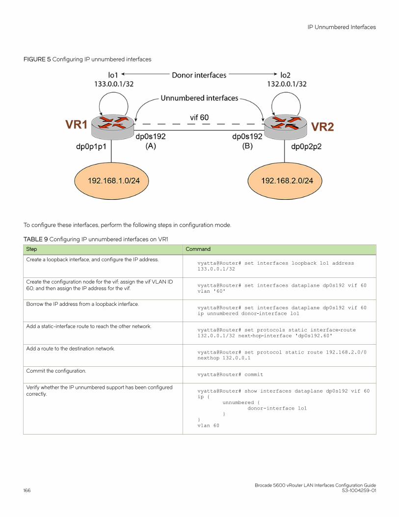
FIGURE 5 Configuring IP unnumbered interfaces
To configure these interfaces, perform the following steps in configuration mode.
TABLE 9 Configuring IP unnumbered interfaces on VR1
Step Command
Create a loopback interface, and configure the IP address. vyatta@Router# set interfaces loopback lo1 address 133.0.0.1/32
Create the configuration node for the vif; assign the vif VLAN ID60; and then assign the IP address for the vif.
vyatta@Router# set interfaces dataplane dp0s192 vif 60 vlan '60'
Borrow the IP address from a loopback interface. vyatta@Router# set interfaces dataplane dp0s192 vif 60 ip unnumbered donor‐interface lo1
Add a static-interface route to reach the other network. vyatta@Router# set protocols static interface‐route 132.0.0.1/32 next‐hop‐interface 'dp0s192.60'
Add a route to the destination network. vyatta@Router# set protocol static route 192.168.2.0/0 nexthop 132.0.0.1
Commit the configuration. vyatta@Router# commit
Verify whether the IP unnumbered support has been configuredcorrectly.
vyatta@Router# show interfaces dataplane dp0s192 vif 60ip { unnumbered { donor-interface lo1 }}vlan 60
IP Unnumbered Interfaces
Brocade 5600 vRouter LAN Interfaces Configuration Guide166 53-1004259-01
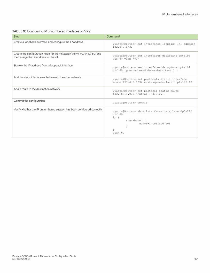
TABLE 10 Configuring IP unnumbered interfaces on VR2
Step Command
Create a loopback interface, and configure the IP address. vyatta@Router# set interfaces loopback lo1 address 132.0.0.1/32
Create the configuration node for the vif; assign the vif VLAN ID 60; andthen assign the IP address for the vif.
vyatta@Router# set interfaces dataplane dp0s192 vif 60 vlan '60'
Borrow the IP address from a loopback interface. vyatta@Router# set interfaces dataplane dp0s192 vif 60 ip unnumbered donor‐interface lo1
Add the static interface route to reach the other network. vyatta@Router# set protocols static interface‐route 133.0.0.1/32 next‐hop‐interface 'dp0s192.60'
Add a route to the destination network. vyatta@Router# set protocol static route 192.168.1.0/0 nexthop 133.0.0.1
Commit the configuration. vyatta@Router# commit
Verify whether the IP unnumbered support has been configured correctly. vyatta@Router# show interfaces dataplane dp0s192 vif 60ip { unnumbered { donor-interface lo1 }}vlan 60
IP Unnumbered Interfaces
Brocade 5600 vRouter LAN Interfaces Configuration Guide53-1004259-01 167

IP Unnumbered Interfaces
Brocade 5600 vRouter LAN Interfaces Configuration Guide168 53-1004259-01

IP Unnumbered Interfaces Commands∙ interfaces dataplane <interface-name> vif <vif-id> ip unnumbered donor-interface <donor-interface-
name> preferred-address <ip-address>..............................................................................................................................................................170
Brocade 5600 vRouter LAN Interfaces Configuration Guide53-1004259-01 169
interfaces dataplane <interface-name> vif <vif-id> ip unnumbered donor-interface <donor-interface-name> preferred-address <ip-address>
Configures the virtual interface of the specified data plane as an IP unnumbered interface with the donor interface and preferredaddress.
Syntaxset interfaces dataplane interface-name vif vif-id ip unnumbered donor-interface donor_interface-name [ preferred-address ip-
address ]
delete interfaces dataplane interface-name vif vif-id ip unnumbered
Parametersinterface-name
The name of a data plane interface. For more information about the supported interface name formats, refer to DataPlane Interface on page 215.
vif-idThe ID of a virtual interface. The ID ranges from 1 through 4094.
donor-interface-nameThe name of the donor data plane or loopback interface.
preferred-address ip-addressSpecifies the borrowed preferred address to use from the donor interface.
ModesConfiguration mode
Configuration Statementinterfaces { dataplane interface-name { vif vif-id { ip { unnumbered { donor-interface donor-interface-name { preferred-address ip-address } } } } }}
Usage GuidelinesUse this command to configure interfaces as unnumbered interfaces.
Use the set form of this command to configure a data plane interface as an unnumbered interface. The preferred address of thedonor interface must be one of the configured addresses on the interface.
IP Unnumbered Interfaces Commands
Brocade 5600 vRouter LAN Interfaces Configuration Guide170 53-1004259-01
Use the delete form of this command to remove an unnumbered interface. To remove the preferred address of the donorinterface, use the following command:
delete interfaces dataplane interface-name vif vif-id ip unnumbered donor-interface donor_interface-name preferred-address
This command has no show form. To display information about unnumbered data plane interfaces and donor interfaces, use show interfaces dataplane on page 78 and show interfaces loopback on page 30.
NOTETo change a donor interface, first set a new donor interface, then delete the one that you want to change.
IP Unnumbered Interfaces Commands
Brocade 5600 vRouter LAN Interfaces Configuration Guide53-1004259-01 171

IP Unnumbered Interfaces Commands
Brocade 5600 vRouter LAN Interfaces Configuration Guide172 53-1004259-01
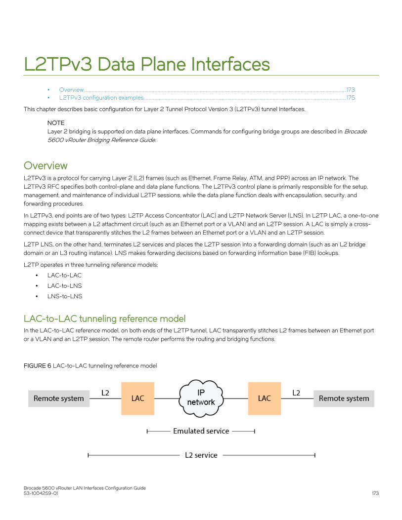
L2TPv3 Data Plane Interfaces∙ Overview................................................................................................................................................................................................................................173∙ L2TPv3 configuration examples.............................................................................................................................................................................175
This chapter describes basic configuration for Layer 2 Tunnel Protocol Version 3 (L2TPv3) tunnel interfaces.
NOTELayer 2 bridging is supported on data plane interfaces. Commands for configuring bridge groups are described in Brocade5600 vRouter Bridging Reference Guide.
OverviewL2TPv3 is a protocol for carrying Layer 2 (L2) frames (such as Ethernet, Frame Relay, ATM, and PPP) across an IP network. TheL2TPv3 RFC specifies both control-plane and data plane functions. The L2TPv3 control plane is primarily responsible for the setup,management, and maintenance of individual L2TP sessions, while the data plane function deals with encapsulation, security, andforwarding procedures.
In L2TPv3, end points are of two types: L2TP Access Concentrator (LAC) and L2TP Network Server (LNS). In L2TP LAC, a one-to-onemapping exists between a L2 attachment circuit (such as an Ethernet port or a VLAN) and an L2TP session. A LAC is simply a cross-connect device that transparently stitches the L2 frames between an Ethernet port or a VLAN and an L2TP session.
L2TP LNS, on the other hand, terminates L2 services and places the L2TP session into a forwarding domain (such as an L2 bridgedomain or an L3 routing instance). LNS makes forwarding decisions based on forwarding information base (FIB) lookups.
L2TP operates in three tunneling reference models:
∙ LAC-to-LAC
∙ LAC-to-LNS
∙ LNS-to-LNS
LAC-to-LAC tunneling reference modelIn the LAC-to-LAC reference model, on both ends of the L2TP tunnel, LAC transparently stitches L2 frames between an Ethernet portor a VLAN and an L2TP session. The remote router performs the routing and bridging functions.
FIGURE 6 LAC-to-LAC tunneling reference model
Brocade 5600 vRouter LAN Interfaces Configuration Guide53-1004259-01 173
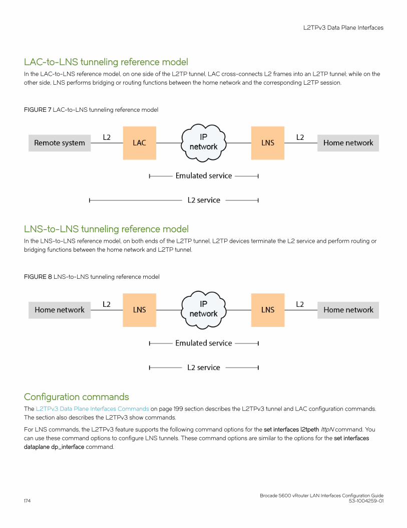
LAC-to-LNS tunneling reference modelIn the LAC-to-LNS reference model, on one side of the L2TP tunnel, LAC cross-connects L2 frames into an L2TP tunnel; while on theother side, LNS performs bridging or routing functions between the home network and the corresponding L2TP session.
FIGURE 7 LAC-to-LNS tunneling reference model
LNS-to-LNS tunneling reference modelIn the LNS-to-LNS reference model, on both ends of the L2TP tunnel, L2TP devices terminate the L2 service and perform routing orbridging functions between the home network and L2TP tunnel.
FIGURE 8 LNS-to-LNS tunneling reference model
Configuration commandsThe L2TPv3 Data Plane Interfaces Commands on page 199 section describes the L2TPv3 tunnel and LAC configuration commands.The section also describes the L2TPv3 show commands.
For LNS commands, the L2TPv3 feature supports the following command options for the set interfaces l2tpeth lttpN command. Youcan use these command options to configure LNS tunnels. These command options are similar to the options for the set interfacesdataplane dp_interface command.
L2TPv3 Data Plane Interfaces
Brocade 5600 vRouter LAN Interfaces Configuration Guide174 53-1004259-01
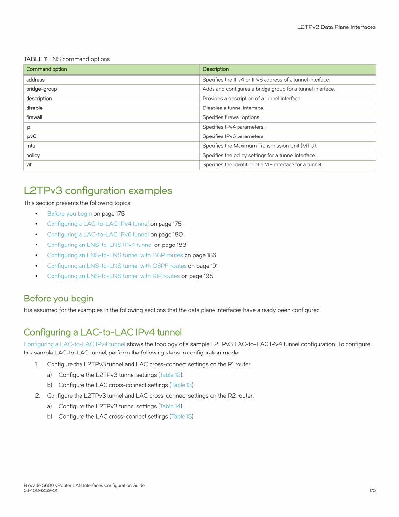
TABLE 11 LNS command options
Command option Description
address Specifies the IPv4 or IPv6 address of a tunnel interface.
bridge-group Adds and configures a bridge group for a tunnel interface.
description Provides a description of a tunnel interface.
disable Disables a tunnel interface.
firewall Specifies firewall options.
ip Specifies IPv4 parameters.
ipv6 Specifies IPv6 parameters.
mtu Specifies the Maximum Transmission Unit (MTU).
policy Specifies the policy settings for a tunnel interface.
vif Specifies the identifier of a VIF interface for a tunnel.
L2TPv3 configuration examplesThis section presents the following topics:
∙ Before you begin on page 175
∙ Configuring a LAC-to-LAC IPv4 tunnel on page 175
∙ Configuring a LAC-to-LAC IPv6 tunnel on page 180
∙ Configuring an LNS-to-LNS IPv4 tunnel on page 183
∙ Configuring an LNS-to-LNS tunnel with BGP routes on page 186
∙ Configuring an LNS-to-LNS tunnel with OSPF routes on page 191
∙ Configuring an LNS-to-LNS tunnel with RIP routes on page 195
Before you beginIt is assumed for the examples in the following sections that the data plane interfaces have already been configured.
Configuring a LAC-to-LAC IPv4 tunnelConfiguring a LAC-to-LAC IPv4 tunnel shows the topology of a sample L2TPv3 LAC-to-LAC IPv4 tunnel configuration. To configurethis sample LAC-to-LAC tunnel, perform the following steps in configuration mode:
1. Configure the L2TPv3 tunnel and LAC cross-connect settings on the R1 router.
a) Configure the L2TPv3 tunnel settings (Table 12).
b) Configure the LAC cross-connect settings (Table 13).
2. Configure the L2TPv3 tunnel and LAC cross-connect settings on the R2 router.
a) Configure the L2TPv3 tunnel settings (Table 14).
b) Configure the LAC cross-connect settings (Table 15).
L2TPv3 Data Plane Interfaces
Brocade 5600 vRouter LAN Interfaces Configuration Guide53-1004259-01 175
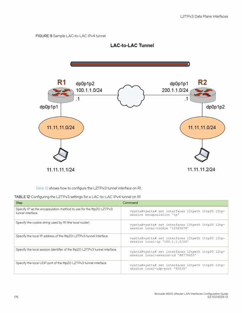
FIGURE 9 Sample LAC-to-LAC IPv4 tunnel
Table 12 shows how to configure the L2TPv3 tunnel interface on R1.
TABLE 12 Configuring the L2TPv3 settings for a LAC-to-LAC IPv4 tunnel on R1
Step Command
Specify IP as the encapsulation method to use for the lttp20 L2TPv3tunnel interface.
vyatta@vyatta# set interfaces l2tpeth lttp20 l2tp-session encapsulation 'ip'
Specify the cookie string used by R1 (the local router). vyatta@vyatta# set interfaces l2tpeth lttp20 l2tp-session local-cookie '12345678'
Specify the local IP address of the lttp20 L2TPv3 tunnel interface. vyatta@vyatta# set interfaces l2tpeth lttp20 l2tp-session local-ip '100.1.1.0/24'
Specify the local session identifier of the lttp20 L2TPv3 tunnel interface. vyatta@vyatta# set interfaces l2tpeth lttp20 l2tp-session local-session-id '88776655'
Specify the local UDP port of the lttp20 L2TPv3 tunnel interface. vyatta@vyatta# set interfaces l2tpeth lttp20 l2tp-session local-udp-port '65535'
L2TPv3 Data Plane Interfaces
Brocade 5600 vRouter LAN Interfaces Configuration Guide176 53-1004259-01
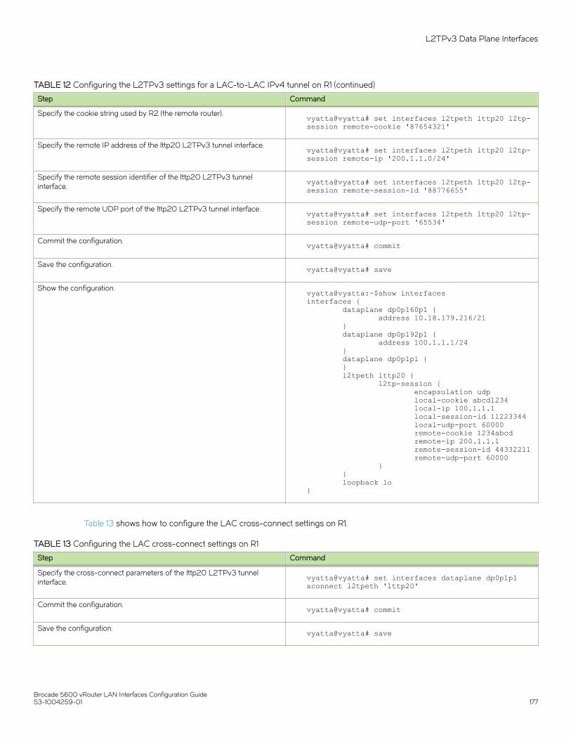
TABLE 12 Configuring the L2TPv3 settings for a LAC-to-LAC IPv4 tunnel on R1 (continued)
Step Command
Specify the cookie string used by R2 (the remote router). vyatta@vyatta# set interfaces l2tpeth lttp20 l2tp-session remote-cookie '87654321'
Specify the remote IP address of the lttp20 L2TPv3 tunnel interface. vyatta@vyatta# set interfaces l2tpeth lttp20 l2tp-session remote-ip '200.1.1.0/24'
Specify the remote session identifier of the lttp20 L2TPv3 tunnelinterface.
vyatta@vyatta# set interfaces l2tpeth lttp20 l2tp-session remote-session-id '88776655'
Specify the remote UDP port of the lttp20 L2TPv3 tunnel interface. vyatta@vyatta# set interfaces l2tpeth lttp20 l2tp-session remote-udp-port '65534'
Commit the configuration. vyatta@vyatta# commit
Save the configuration. vyatta@vyatta# save
Show the configuration. vyatta@vyatta:~$show interfacesinterfaces { dataplane dp0p160p1 { address 10.18.179.216/21 } dataplane dp0p192p1 { address 100.1.1.1/24 } dataplane dp0p1p1 { } l2tpeth lttp20 { l2tp-session { encapsulation udp local-cookie abcd1234 local-ip 100.1.1.1 local-session-id 11223344 local-udp-port 60000 remote-cookie 1234abcd remote-ip 200.1.1.1 remote-session-id 44332211 remote-udp-port 60000 } } loopback lo}
Table 13 shows how to configure the LAC cross-connect settings on R1.
TABLE 13 Configuring the LAC cross-connect settings on R1
Step Command
Specify the cross-connect parameters of the lttp20 L2TPv3 tunnelinterface.
vyatta@vyatta# set interfaces dataplane dp0p1p1 xconnect l2tpeth 'lttp20'
Commit the configuration. vyatta@vyatta# commit
Save the configuration. vyatta@vyatta# save
L2TPv3 Data Plane Interfaces
Brocade 5600 vRouter LAN Interfaces Configuration Guide53-1004259-01 177
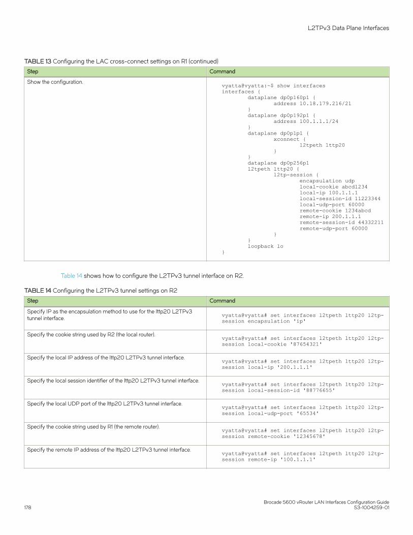
TABLE 13 Configuring the LAC cross-connect settings on R1 (continued)
Step Command
Show the configuration. vyatta@vyatta:~$ show interfacesinterfaces { dataplane dp0p160p1 { address 10.18.179.216/21 } dataplane dp0p192p1 { address 100.1.1.1/24 } dataplane dp0p1p1 { xconnect { l2tpeth lttp20 } } dataplane dp0p256p1 l2tpeth lttp20 { l2tp-session { encapsulation udp local-cookie abcd1234 local-ip 100.1.1.1 local-session-id 11223344 local-udp-port 60000 remote-cookie 1234abcd remote-ip 200.1.1.1 remote-session-id 44332211 remote-udp-port 60000 } } loopback lo}
Table 14 shows how to configure the L2TPv3 tunnel interface on R2.
TABLE 14 Configuring the L2TPv3 tunnel settings on R2
Step Command
Specify IP as the encapsulation method to use for the lttp20 L2TPv3tunnel interface.
vyatta@vyatta# set interfaces l2tpeth lttp20 l2tp-session encapsulation 'ip'
Specify the cookie string used by R2 (the local router). vyatta@vyatta# set interfaces l2tpeth lttp20 l2tp-session local-cookie '87654321'
Specify the local IP address of the lttp20 L2TPv3 tunnel interface. vyatta@vyatta# set interfaces l2tpeth lttp20 l2tp-session local-ip '200.1.1.1'
Specify the local session identifier of the lttp20 L2TPv3 tunnel interface. vyatta@vyatta# set interfaces l2tpeth lttp20 l2tp-session local-session-id '88776655'
Specify the local UDP port of the lttp20 L2TPv3 tunnel interface. vyatta@vyatta# set interfaces l2tpeth lttp20 l2tp-session local-udp-port '65534'
Specify the cookie string used by R1 (the remote router). vyatta@vyatta# set interfaces l2tpeth lttp20 l2tp-session remote-cookie '12345678'
Specify the remote IP address of the lttp20 L2TPv3 tunnel interface. vyatta@vyatta# set interfaces l2tpeth lttp20 l2tp-session remote-ip '100.1.1.1'
L2TPv3 Data Plane Interfaces
Brocade 5600 vRouter LAN Interfaces Configuration Guide178 53-1004259-01
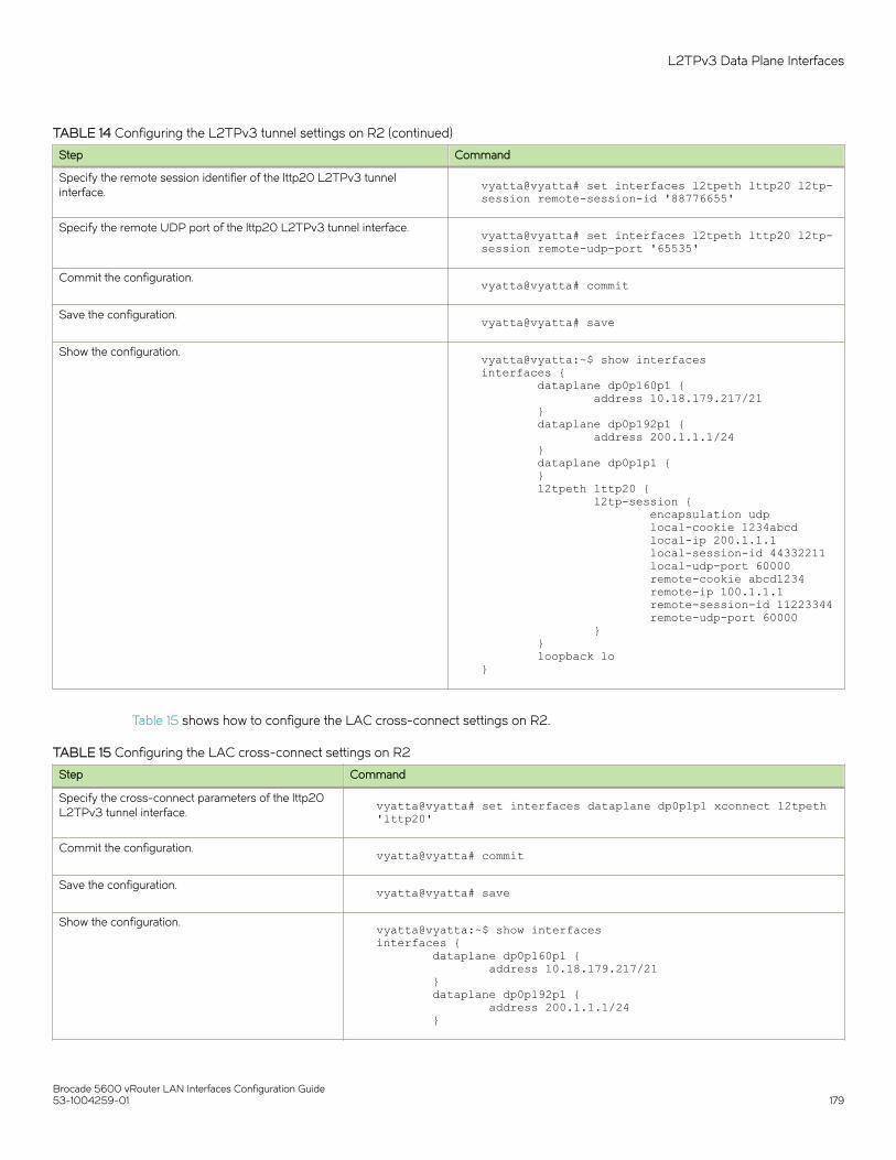
TABLE 14 Configuring the L2TPv3 tunnel settings on R2 (continued)
Step Command
Specify the remote session identifier of the lttp20 L2TPv3 tunnelinterface.
vyatta@vyatta# set interfaces l2tpeth lttp20 l2tp-session remote-session-id '88776655'
Specify the remote UDP port of the lttp20 L2TPv3 tunnel interface. vyatta@vyatta# set interfaces l2tpeth lttp20 l2tp-session remote-udp-port '65535'
Commit the configuration. vyatta@vyatta# commit
Save the configuration. vyatta@vyatta# save
Show the configuration. vyatta@vyatta:~$ show interfacesinterfaces { dataplane dp0p160p1 { address 10.18.179.217/21 } dataplane dp0p192p1 { address 200.1.1.1/24 } dataplane dp0p1p1 { } l2tpeth lttp20 { l2tp-session { encapsulation udp local-cookie 1234abcd local-ip 200.1.1.1 local-session-id 44332211 local-udp-port 60000 remote-cookie abcd1234 remote-ip 100.1.1.1 remote-session-id 11223344 remote-udp-port 60000 } } loopback lo}
Table 15 shows how to configure the LAC cross-connect settings on R2.
TABLE 15 Configuring the LAC cross-connect settings on R2
Step Command
Specify the cross-connect parameters of the lttp20L2TPv3 tunnel interface.
vyatta@vyatta# set interfaces dataplane dp0p1p1 xconnect 12tpeth 'lttp20'
Commit the configuration. vyatta@vyatta# commit
Save the configuration. vyatta@vyatta# save
Show the configuration. vyatta@vyatta:~$ show interfacesinterfaces { dataplane dp0p160p1 { address 10.18.179.217/21 } dataplane dp0p192p1 { address 200.1.1.1/24 }
L2TPv3 Data Plane Interfaces
Brocade 5600 vRouter LAN Interfaces Configuration Guide53-1004259-01 179
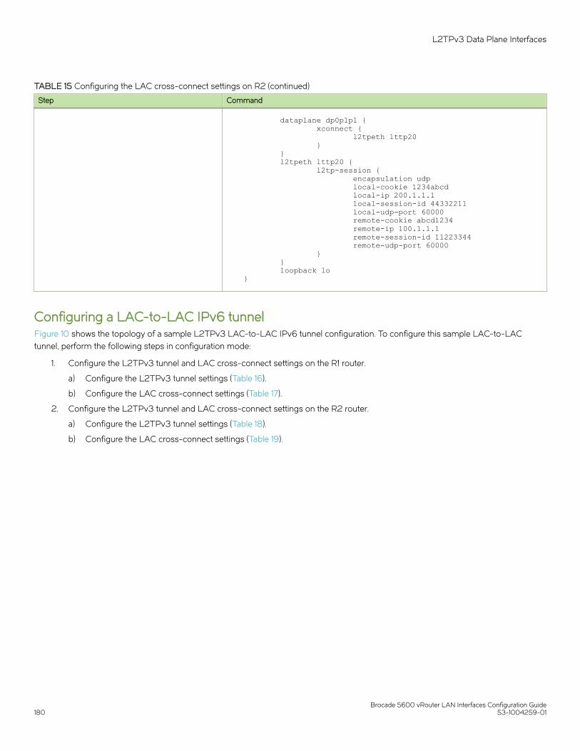
TABLE 15 Configuring the LAC cross-connect settings on R2 (continued)
Step Command
dataplane dp0p1p1 { xconnect { l2tpeth lttp20 } } l2tpeth lttp20 { l2tp-session { encapsulation udp local-cookie 1234abcd local-ip 200.1.1.1 local-session-id 44332211 local-udp-port 60000 remote-cookie abcd1234 remote-ip 100.1.1.1 remote-session-id 11223344 remote-udp-port 60000 } } loopback lo}
Configuring a LAC-to-LAC IPv6 tunnelFigure 10 shows the topology of a sample L2TPv3 LAC-to-LAC IPv6 tunnel configuration. To configure this sample LAC-to-LACtunnel, perform the following steps in configuration mode:
1. Configure the L2TPv3 tunnel and LAC cross-connect settings on the R1 router.
a) Configure the L2TPv3 tunnel settings (Table 16).
b) Configure the LAC cross-connect settings (Table 17).
2. Configure the L2TPv3 tunnel and LAC cross-connect settings on the R2 router.
a) Configure the L2TPv3 tunnel settings (Table 18).
b) Configure the LAC cross-connect settings (Table 19).
L2TPv3 Data Plane Interfaces
Brocade 5600 vRouter LAN Interfaces Configuration Guide180 53-1004259-01
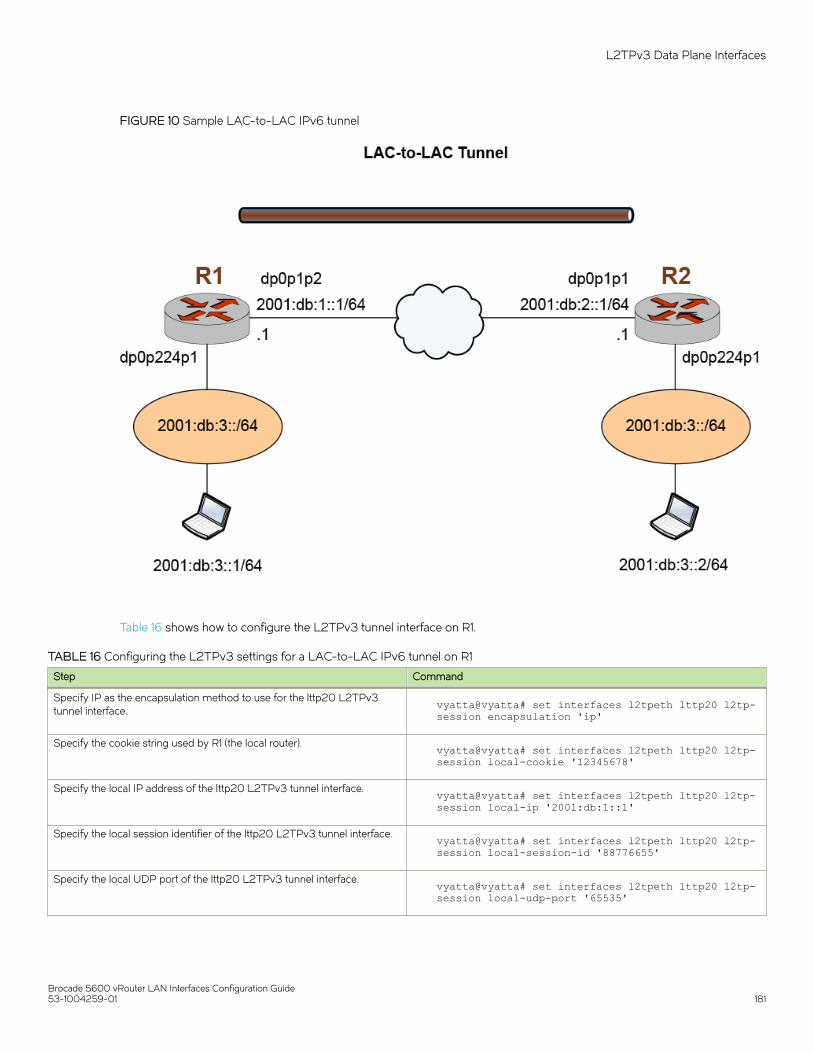
FIGURE 10 Sample LAC-to-LAC IPv6 tunnel
Table 16 shows how to configure the L2TPv3 tunnel interface on R1.
TABLE 16 Configuring the L2TPv3 settings for a LAC-to-LAC IPv6 tunnel on R1
Step Command
Specify IP as the encapsulation method to use for the lttp20 L2TPv3tunnel interface.
vyatta@vyatta# set interfaces l2tpeth lttp20 l2tp-session encapsulation 'ip'
Specify the cookie string used by R1 (the local router). vyatta@vyatta# set interfaces l2tpeth lttp20 l2tp-session local-cookie '12345678'
Specify the local IP address of the lttp20 L2TPv3 tunnel interface. vyatta@vyatta# set interfaces l2tpeth lttp20 l2tp-session local-ip '2001:db:1::1'
Specify the local session identifier of the lttp20 L2TPv3 tunnel interface. vyatta@vyatta# set interfaces l2tpeth lttp20 l2tp-session local-session-id '88776655'
Specify the local UDP port of the lttp20 L2TPv3 tunnel interface. vyatta@vyatta# set interfaces l2tpeth lttp20 l2tp-session local-udp-port '65535'
L2TPv3 Data Plane Interfaces
Brocade 5600 vRouter LAN Interfaces Configuration Guide53-1004259-01 181
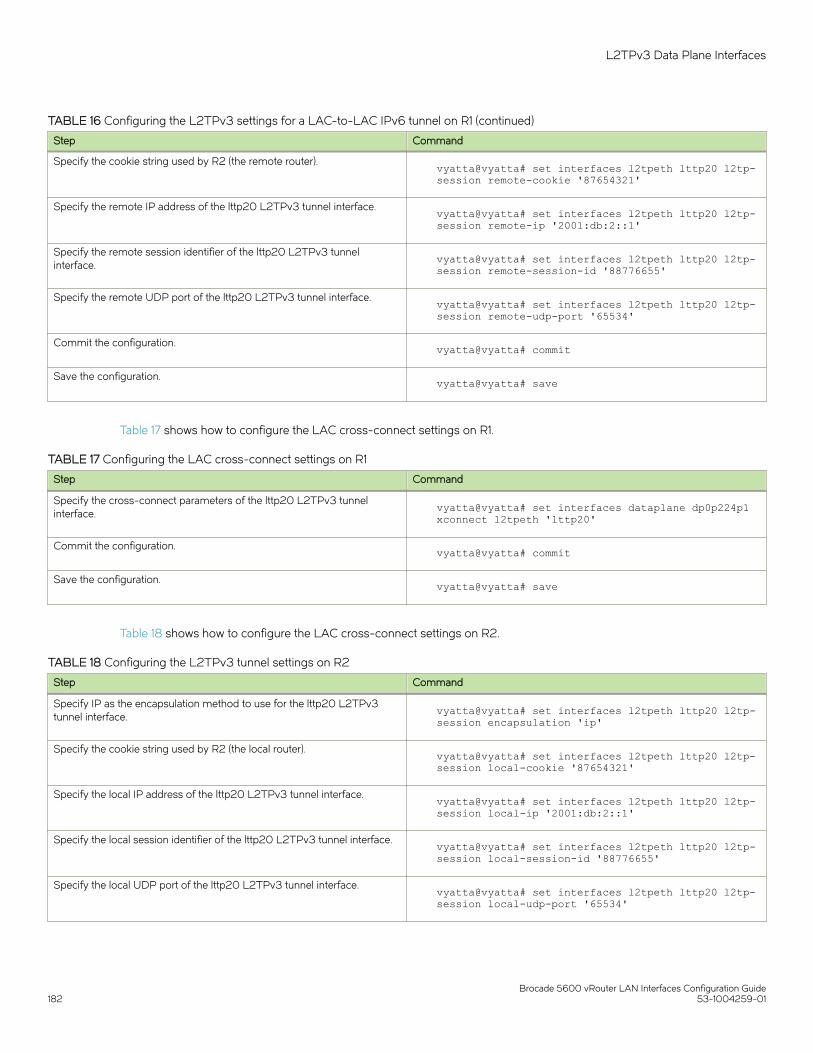
TABLE 16 Configuring the L2TPv3 settings for a LAC-to-LAC IPv6 tunnel on R1 (continued)
Step Command
Specify the cookie string used by R2 (the remote router). vyatta@vyatta# set interfaces l2tpeth lttp20 l2tp-session remote-cookie '87654321'
Specify the remote IP address of the lttp20 L2TPv3 tunnel interface. vyatta@vyatta# set interfaces l2tpeth lttp20 l2tp-session remote-ip '2001:db:2::1'
Specify the remote session identifier of the lttp20 L2TPv3 tunnelinterface.
vyatta@vyatta# set interfaces l2tpeth lttp20 l2tp-session remote-session-id '88776655'
Specify the remote UDP port of the lttp20 L2TPv3 tunnel interface. vyatta@vyatta# set interfaces l2tpeth lttp20 l2tp-session remote-udp-port '65534'
Commit the configuration. vyatta@vyatta# commit
Save the configuration. vyatta@vyatta# save
Table 17 shows how to configure the LAC cross-connect settings on R1.
TABLE 17 Configuring the LAC cross-connect settings on R1
Step Command
Specify the cross-connect parameters of the lttp20 L2TPv3 tunnelinterface.
vyatta@vyatta# set interfaces dataplane dp0p224p1 xconnect l2tpeth 'lttp20'
Commit the configuration. vyatta@vyatta# commit
Save the configuration. vyatta@vyatta# save
Table 18 shows how to configure the LAC cross-connect settings on R2.
TABLE 18 Configuring the L2TPv3 tunnel settings on R2
Step Command
Specify IP as the encapsulation method to use for the lttp20 L2TPv3tunnel interface.
vyatta@vyatta# set interfaces l2tpeth lttp20 l2tp-session encapsulation 'ip'
Specify the cookie string used by R2 (the local router). vyatta@vyatta# set interfaces l2tpeth lttp20 l2tp-session local-cookie '87654321'
Specify the local IP address of the lttp20 L2TPv3 tunnel interface. vyatta@vyatta# set interfaces l2tpeth lttp20 l2tp-session local-ip '2001:db:2::1'
Specify the local session identifier of the lttp20 L2TPv3 tunnel interface. vyatta@vyatta# set interfaces l2tpeth lttp20 l2tp-session local-session-id '88776655'
Specify the local UDP port of the lttp20 L2TPv3 tunnel interface. vyatta@vyatta# set interfaces l2tpeth lttp20 l2tp-session local-udp-port '65534'
L2TPv3 Data Plane Interfaces
Brocade 5600 vRouter LAN Interfaces Configuration Guide182 53-1004259-01
TABLE 18 Configuring the L2TPv3 tunnel settings on R2 (continued)
Step Command
Specify the cookie string used by R1 (the remote router). vyatta@vyatta# set interfaces l2tpeth lttp20 l2tp-session remote-cookie '12345678'
Specify the remote IP address of the lttp20 L2TPv3 tunnel interface. vyatta@vyatta# set interfaces l2tpeth lttp20 l2tp-session remote-ip '2001:db:1::1'
Specify the remote session identifier of the lttp20 L2TPv3 tunnelinterface.
vyatta@vyatta# set interfaces l2tpeth lttp20 l2tp-session remote-session-id '88776655'
Specify the remote UDP port of the lttp20 L2TPv3 tunnel interface. vyatta@vyatta# set interfaces l2tpeth lttp20 l2tp-session remote-udp-port '65535'
Commit the configuration. vyatta@vyatta# commit
Save the configuration. vyatta@vyatta# save
Table 19 shows how to configure the LAC cross-connect settings on R2.
TABLE 19 Configuring the LAC cross-connect settings on R2
Step Command
Specify the cross-connect parameters of the lttp20 L2TPv3tunnel interface.
vyatta@vyatta# set interfaces dataplane dp0p224p1 xconnect l2tpeth 'lttp20'
Commit the configuration. vyatta@vyatta# commit
Save the configuration. vyatta@vyatta# save
Configuring an LNS-to-LNS IPv4 tunnelConfiguring an LNS-to-LNS IPv4 tunnel shows the topology of a sample L2TPv3 LNS-to-LNS IPv4 tunnel configuration. To configurethis sample LNS-to-LNS tunnel, perform the following steps in configuration mode.
1. Configure the L2TPv3 tunnel settings and the LNS settings on the R1 router.
a) Configure the L2TPv3 tunnel settings (Table 20).
b) Configure the LNS settings (Table 21).
2. Configure the L2TPv3 tunnel settings and LNS settings on the R2 router.
a) Configure the L2TPv3 tunnel settings (Table 22).
b) Configure the LNS settings (Table 23).
L2TPv3 Data Plane Interfaces
Brocade 5600 vRouter LAN Interfaces Configuration Guide53-1004259-01 183
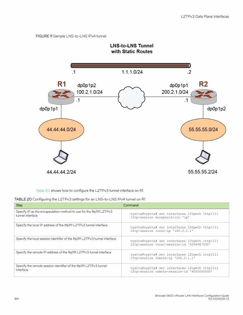
FIGURE 11 Sample LNS-to-LNS IPv4 tunnel
Table 20 shows how to configure the L2TPv3 tunnel interface on R1.
TABLE 20 Configuring the L2TPv3 settings for an LNS-to-LNS IPv4 tunnel on R1
Step Command
Specify IP as the encapsulation method to use for the lttp1111 L2TPv3tunnel interface.
vyatta@vyatta# set interfaces l2tpeth lttp1111 l2tp-session encapsulation 'ip'
Specify the local IP address of the lttp1111 L2TPv3 tunnel interface. vyatta@vyatta# set interfaces l2tpeth lttp1111 l2tp-session local-ip '100.2.1.1'
Specify the local session identifier of the lttp1111 L2TPv3 tunnel interface. vyatta@vyatta# set interfaces l2tpeth lttp1111 l2tp-session local-session-id '4294967295'
Specify the remote IP address of the lttp1111 L2TPv3 tunnel interface. vyatta@vyatta# set interfaces l2tpeth lttp1111 l2tp-session remote-ip '200.2.1.1'
Specify the remote session identifier of the lttp1111 L2TPv3 tunnelinterface.
vyatta@vyatta# set interfaces l2tpeth lttp1111 l2tp-session remote-session-id '4000000000'
L2TPv3 Data Plane Interfaces
Brocade 5600 vRouter LAN Interfaces Configuration Guide184 53-1004259-01
TABLE 20 Configuring the L2TPv3 settings for an LNS-to-LNS IPv4 tunnel on R1 (continued)
Step Command
Specify the IP address of the tunnel interface to which the router isconnected.
vyatta@vyatta# set interfaces l2tpeth lttp1111 address '1.1.1.1/24'
Commit the configuration. vyatta@vyatta# commit
Save the configuration. vyatta@vyatta# save
Table 21 shows how to configure on R1 the next hop for traffic that is destined for the 55.55.55.0/24 network.
TABLE 21 Configuring the next hop for 55.55.55.0/24 traffic on R1
Step Command
Specify the IP address of the interface at the other end of the tunnel (1.1.1.2)as the next hop for traffic that is destined for the 55.55.55.0/24 network.
For more information about this command, refer to Basic RoutingConfiguration Guide.
vyatta@vyatta# set protocols static route 55.55.55.0/24 next-hop '1.1.1.2'
Commit the configuration. vyatta@vyatta# commit
Save the configuration. vyatta@vyatta# save
Show the route. vyatta@vyatta# run show ip route 55.55.55.2
Routing entry for 55.55.55.0/24 Known via "static", distance 1, metric 0, best * 1.1.1.2, via lttp1111
Exit the configuration mode. vyatta@vyatta# exit
Show the configuration. vyatta@vyatta:~$ show interfaces l2tpeth lttp1111
address 1.1.1.1/24l2tp-session { encapsulation ip local-ip 100.2.1.1 local-session-id 4294967295 remote-ip 200.2.1.1 remote-session-id 4000000000}
Table 22 shows how to configure the L2TPv3 tunnel interface on R2.
TABLE 22 Configuring the L2TPv3 settings for an LNS-to-LNS IPv4 tunnel on R2
Step Command
Specify IP as the encapsulation method to use for the lttp1111 L2TPv3tunnel interface.
vyatta@vyatta# set interfaces l2tpeth lttp1111 l2tp-session encapsulation 'ip'
Specify the local IP address of the lttp1111 L2TPv3 tunnel interface. vyatta@vyatta# set interfaces l2tpeth lttp1111 l2tp-session local-ip '200.2.1.1'
L2TPv3 Data Plane Interfaces
Brocade 5600 vRouter LAN Interfaces Configuration Guide53-1004259-01 185
TABLE 22 Configuring the L2TPv3 settings for an LNS-to-LNS IPv4 tunnel on R2 (continued)
Step Command
Specify the local session identifier of the lttp1111 L2TPv3 tunnel interface. vyatta@vyatta# set interfaces l2tpeth lttp1111 l2tp-session local-session-id '4294967295'
Specify the remote IP address of the lttp1111 L2TPv3 tunnel interface. vyatta@vyatta# set interfaces l2tpeth lttp1111 l2tp-session remote-ip '100.2.1.1'
Specify the remote session identifier of the lttp1111 L2TPv3 tunnelinterface.
vyatta@vyatta# set interfaces l2tpeth lttp1111 l2tp-session remote-session-id '4000000000'
Specify the IP address of the tunnel interface to which the router isconnected.
vyatta@vyatta# set interfaces l2tpeth lttp1111 address '1.1.1.2/24'
Commit the configuration. vyatta@vyatta# commit
Save the configuration. vyatta@vyatta# save
Table 23 shows how to configure on R2 the next hop for traffic that is destined for the 44.44.44.0/24 network.
TABLE 23 Configuring the next hop for 44.44.44.0/24 traffic on R2
Step Command
Specify the IP address of the interface at the other end of the tunnel (1.1.1.1)as the next hop for traffic that is destined for the 44.44.44.0/24 network.
For more information about this command, refer to Basic RoutingConfiguration Guide.
vyatta@vyatta# set protocols static route 44.44.44.0/24 next-hop '1.1.1.1'
Commit the configuration. vyatta@vyatta# commit
Save the configuration. vyatta@vyatta# save
Configuring an LNS-to-LNS tunnel with BGP routesConfiguring an LNS-to-LNS tunnel with BGP routes shows the topology of a sample L2TPv3 LNS-to-LNS IPv4 tunnel with BorderGateway Protocol (BGP) configuration. To configure this sample LNS-to-LNS tunnel, perform the following steps in configuration mode.
1. Configure the L2TPv3 tunnel settings and the LNS settings on the R1 router.
a) Configure the L2TPv3 tunnel settings (Table 24).
b) Configure the BGP settings (Table 25).
2. Configure the L2TPv3 tunnel settings and LNS settings on the R2 router.
a) Configure the L2TPv3 tunnel settings (Table 26).
b) Configure the BGP settings (Table 27).
L2TPv3 Data Plane Interfaces
Brocade 5600 vRouter LAN Interfaces Configuration Guide186 53-1004259-01
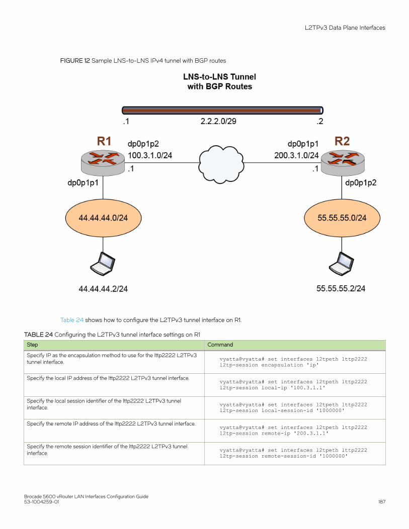
FIGURE 12 Sample LNS-to-LNS IPv4 tunnel with BGP routes
Table 24 shows how to configure the L2TPv3 tunnel interface on R1.
TABLE 24 Configuring the L2TPv3 tunnel interface settings on R1
Step Command
Specify IP as the encapsulation method to use for the lttp2222 L2TPv3tunnel interface.
vyatta@vyatta# set interfaces l2tpeth lttp2222 l2tp-session encapsulation 'ip'
Specify the local IP address of the lttp2222 L2TPv3 tunnel interface. vyatta@vyatta# set interfaces l2tpeth lttp2222 l2tp-session local-ip '100.3.1.1'
Specify the local session identifier of the lttp2222 L2TPv3 tunnelinterface.
vyatta@vyatta# set interfaces l2tpeth lttp2222 l2tp-session local-session-id '1000000'
Specify the remote IP address of the lttp2222 L2TPv3 tunnel interface. vyatta@vyatta# set interfaces l2tpeth lttp2222 l2tp-session remote-ip '200.3.1.1'
Specify the remote session identifier of the lttp2222 L2TPv3 tunnelinterface.
vyatta@vyatta# set interfaces l2tpeth lttp2222 l2tp-session remote-session-id '1000000'
L2TPv3 Data Plane Interfaces
Brocade 5600 vRouter LAN Interfaces Configuration Guide53-1004259-01 187
TABLE 24 Configuring the L2TPv3 tunnel interface settings on R1 (continued)
Step Command
Specify the IP address of the tunnel interface to which the router isconnected.
vyatta@vyatta# set interfaces l2tpeth lttp2222 address '2.2.2.1/29'
Commit the configuration. vyatta@vyatta# commit
Save the configuration. vyatta@vyatta# save
Table 25 shows how to configure the BGP settings for the tunnel on R1. For more information about configuring BGPsettings, refer to BGP Reference Guide.
TABLE 25 Configuring the BGP settings of the LNS-to-LNS tunnel on R1
Step Command
Specify the 44.44.44.0/24 network as the network to be advertised bythe BGP routing process.
vyatta@vyatta# set protocols bgp 100 address-family ipv4-unicast network '44.44.44.0/24'
Direct the router to store received routing updates. vyatta@vyatta# set protocols bgp 100 neighbor 2.2.2.2 address-family ipv4-unicast soft-reconfiguration 'inbound'
Specify 200 as the autonomous system (AS) number of the neighbor. vyatta@vyatta# set protocols bgp 100 neighbor 2.2.2.2 remote-as '200'
Set the fixed BGP router ID for the router to 2.2.2.1. This setting overridesthe automatic ID selection process.
vyatta@vyatta# set protocols bgp 100 parameters router-id '2.2.2.1'
Commit the configuration. vyatta@vyatta# commit
Save the configuration. vyatta@vyatta# save
Show the l2tpeth configuration. vyatta@vyatta# run show l2tpeth
L2tpeth interface: lttp2222 Port: 0, ifIndex: 19 Mac: 96:89:f9:e7:6e:d1 Addresses: inet 2.2.2.1/29, broadcast 2.2.2.7 inet6 fe80::9489:f9ff:fee7:6ed1/64, scope Link L2TPv3: Encap IP Local Address: 100.3.1.1 Peer Address: 200.3.1.1 Local Session: 2000000 Peer Session: 2000000 Local Cookie: 00 Peer Cookie: 00 Statistics: Input bytes : 191229 Output bytes : 144752 Input packets : 2314 Output packets : 1143 Input multicast : 107
L2TPv3 Data Plane Interfaces
Brocade 5600 vRouter LAN Interfaces Configuration Guide188 53-1004259-01
TABLE 25 Configuring the BGP settings of the LNS-to-LNS tunnel on R1 (continued)
Step Command
Show the configuration information for lttp2222. vyatta@vyatta# run show interfaces lttp2222lttp2222: <BROADCAST,MULTICAST,UP,LOWER_UP> mtu 1488 qdisc pfifo_fast state UNKNOWN group default qlen 1000 link/ether 96:89:f9:e7:6e:d1 brd ff:ff:ff:ff:ff:ff inet 2.2.2.1/29 brd 2.2.2.7 scope global lttp2222 valid_lft forever preferred_lft forever inet6 fe80::9489:f9ff:fee7:6ed1/64 scope link valid_lft forever preferred_lft forever
RX: bytes packets errors dropped overrun mcast 86696 1082 0 0 0 0 TX: bytes packets errors dropped carrier collisions 85646 1118 0 0 0 0
Show a summary of the BGP settings. vyatta@vyatta# run show ip bgp summaryBGP router identifier 2.2.2.1, local AS number 100BGP table version is 1922 BGP AS-PATH entries0 BGP community entries
IPv4 Unicast address family:Neighbor V AS MsgRcvd MsgSent TblVer InQ OutQ Up/Down Statd2.2.2.2 4 200 383 383 192 0 0 03:10:16 1Total number of neighbors 1
Show the BGP settings. vyatta@vyatta# run show ip bgpBGP table version is 192, local router ID is 2.2.2.1Status codes: s suppressed, d damped, h history, * valid, > best, i - internal, l - labeled S StaleOrigin codes: i - IGP, e - EGP, ? - incomplete
Network Next Hop Metric LocPrf Weight Path*> 44.44.44.0/24 0.0.0.0 100 32768 i*> 55.55.55.0/24 2.2.2.2 0 0 200 i
Total number of prefixes 2
Show the route information for the 55.55.55.2 system. vyatta@vyatta# run show ip route 55.55.55.2Routing entry for 55.55.55.0/24 Known via "bgp", distance 20, metric 0, best Last update 00:04:06 ago * 2.2.2.2, via lttp2222
Table 26 shows how to configure the L2TPv3 tunnel interface on R2.
L2TPv3 Data Plane Interfaces
Brocade 5600 vRouter LAN Interfaces Configuration Guide53-1004259-01 189
TABLE 26 Configuring the L2TPv3 tunnel interface settings on R2
Step Command
Specify IP as the encapsulation method to use for the lttp2222 L2TPv3tunnel interface.
vyatta@vyatta# set interfaces l2tpeth lttp2222 l2tp-session encapsulation 'ip'
Specify the local IP address of the lttp2222 L2TPv3 tunnel interface. vyatta@vyatta# set interfaces l2tpeth lttp2222 l2tp-session local-ip '200.3.1.1'
Specify the local session identifier of the lttp2222 L2TPv3 tunnelinterface.
vyatta@vyatta# set interfaces l2tpeth lttp2222 l2tp-session local-session-id '2000000'
Specify the remote IP address of the lttp2222 L2TPv3 tunnel interface. vyatta@vyatta# set interfaces l2tpeth lttp2222 l2tp-session remote-ip '100.3.1.1'
Specify the remote session identifier of the lttp2222 L2TPv3 tunnelinterface.
vyatta@vyatta# set interfaces l2tpeth lttp2222 l2tp-session remote-session-id '2000000'
Specify the IP address of the tunnel interface to which the router isconnected.
vyatta@vyatta# set interfaces l2tpeth lttp2222 address '2.2.2.2/29'
Commit the configuration. vyatta@vyatta# commit
Save the configuration. vyatta@vyatta# save
Table 27 shows how to configure the BGP settings for the tunnel on R2. For more information about configuring BGPsettings, refer to BGP Reference Guide.
TABLE 27 Configuring the BGP settings of the LNS-to-LNS tunnel on R2
Step Command
Specify the 55.55.55.0/24 network as the network to be advertised bythe BGP routing process.
vyatta@vyatta# set protocols bgp 100 address-family ipv4-unicast network '55.55.55.0/24'
Direct the router to store received routing updates. vyatta@vyatta# set protocols bgp 100 neighbor 2.2.2.1 address-family ipv4-unicast soft-reconfiguration 'inbound'
Specify 100 as the AS number of the neighbor. vyatta@vyatta# set protocols bgp 100 neighbor 2.2.2.1 remote-as '200'
Set the fixed BGP router ID for the router to 2.2.2.2. This setting overridesthe automatic ID selection process.
vyatta@vyatta# set protocols bgp 100 parameters router-id '2.2.2.2'
Commit the configuration. vyatta@vyatta# commit
Save the configuration. vyatta@vyatta# save
L2TPv3 Data Plane Interfaces
Brocade 5600 vRouter LAN Interfaces Configuration Guide190 53-1004259-01
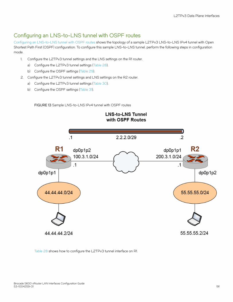
Configuring an LNS-to-LNS tunnel with OSPF routesConfiguring an LNS-to-LNS tunnel with OSPF routes shows the topology of a sample L2TPv3 LNS-to-LNS IPv4 tunnel with OpenShortest Path First (OSPF) configuration. To configure this sample LNS-to-LNS tunnel, perform the following steps in configurationmode.
1. Configure the L2TPv3 tunnel settings and the LNS settings on the R1 router.
a) Configure the L2TPv3 tunnel settings (Table 28).
b) Configure the OSPF settings (Table 29).
2. Configure the L2TPv3 tunnel settings and LNS settings on the R2 router.
a) Configure the L2TPv3 tunnel settings (Table 30).
b) Configure the OSPF settings (Table 31).
FIGURE 13 Sample LNS-to-LNS IPv4 tunnel with OSPF routes
Table 28 shows how to configure the L2TPv3 tunnel interface on R1.
L2TPv3 Data Plane Interfaces
Brocade 5600 vRouter LAN Interfaces Configuration Guide53-1004259-01 191
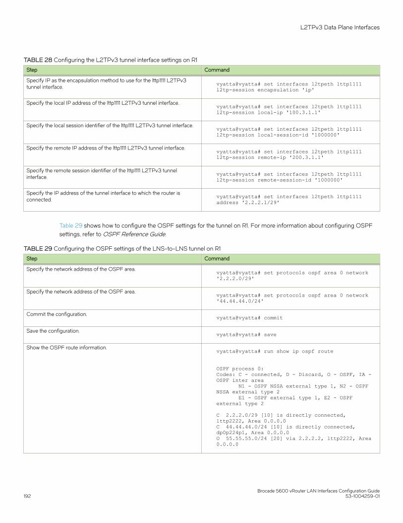
TABLE 28 Configuring the L2TPv3 tunnel interface settings on R1
Step Command
Specify IP as the encapsulation method to use for the lttp1111 L2TPv3tunnel interface.
vyatta@vyatta# set interfaces l2tpeth lttp1111 l2tp-session encapsulation 'ip'
Specify the local IP address of the lttp1111 L2TPv3 tunnel interface. vyatta@vyatta# set interfaces l2tpeth lttp1111 l2tp-session local-ip '100.3.1.1'
Specify the local session identifier of the lttp1111 L2TPv3 tunnel interface. vyatta@vyatta# set interfaces l2tpeth lttp1111 l2tp-session local-session-id '1000000'
Specify the remote IP address of the lttp1111 L2TPv3 tunnel interface. vyatta@vyatta# set interfaces l2tpeth lttp1111 l2tp-session remote-ip '200.3.1.1'
Specify the remote session identifier of the lttp1111 L2TPv3 tunnelinterface.
vyatta@vyatta# set interfaces l2tpeth lttp1111 l2tp-session remote-session-id '1000000'
Specify the IP address of the tunnel interface to which the router isconnected.
vyatta@vyatta# set interfaces l2tpeth lttp1111 address '2.2.2.1/29'
Table 29 shows how to configure the OSPF settings for the tunnel on R1. For more information about configuring OSPFsettings, refer to OSPF Reference Guide.
TABLE 29 Configuring the OSPF settings of the LNS-to-LNS tunnel on R1
Step Command
Specify the network address of the OSPF area. vyatta@vyatta# set protocols ospf area 0 network '2.2.2.0/29'
Specify the network address of the OSPF area. vyatta@vyatta# set protocols ospf area 0 network '44.44.44.0/24'
Commit the configuration. vyatta@vyatta# commit
Save the configuration. vyatta@vyatta# save
Show the OSPF route information. vyatta@vyatta# run show ip ospf route
OSPF process 0:Codes: C - connected, D - Discard, O - OSPF, IA - OSPF inter area N1 - OSPF NSSA external type 1, N2 - OSPF NSSA external type 2 E1 - OSPF external type 1, E2 - OSPF external type 2
C 2.2.2.0/29 [10] is directly connected, lttp2222, Area 0.0.0.0C 44.44.44.0/24 [10] is directly connected, dp0p224p1, Area 0.0.0.0O 55.55.55.0/24 [20] via 2.2.2.2, lttp2222, Area 0.0.0.0
L2TPv3 Data Plane Interfaces
Brocade 5600 vRouter LAN Interfaces Configuration Guide192 53-1004259-01
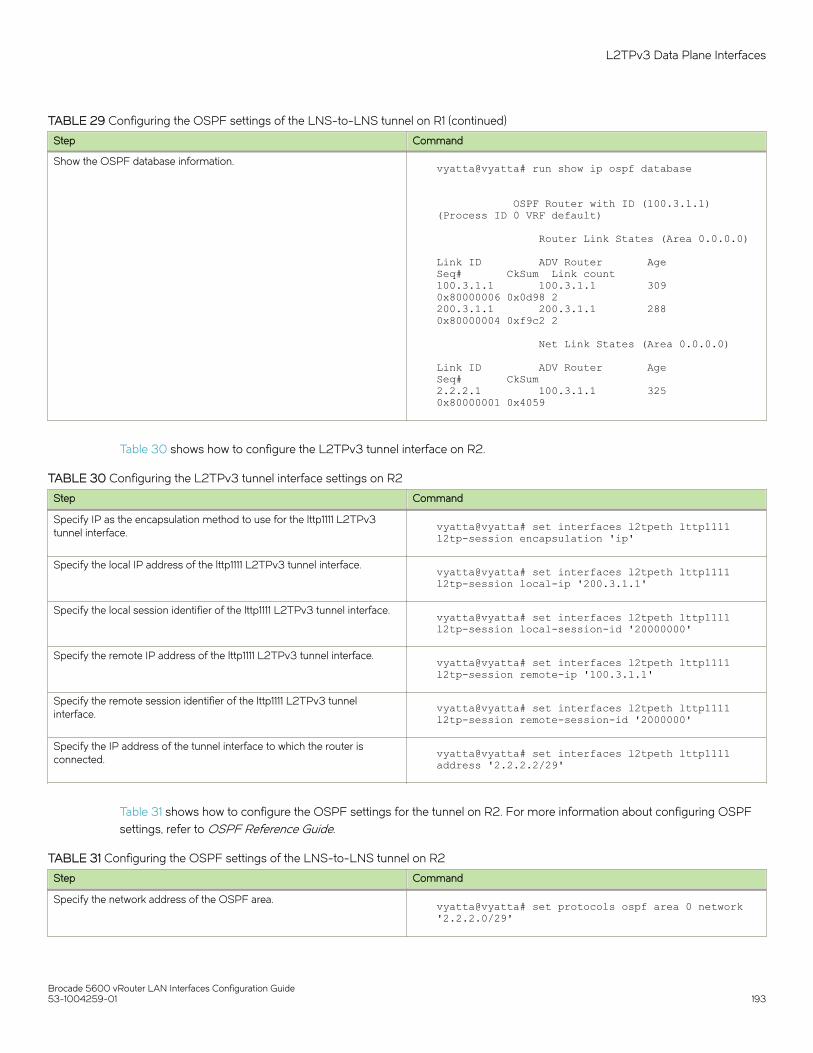
TABLE 29 Configuring the OSPF settings of the LNS-to-LNS tunnel on R1 (continued)
Step Command
Show the OSPF database information. vyatta@vyatta# run show ip ospf database
OSPF Router with ID (100.3.1.1) (Process ID 0 VRF default)
Router Link States (Area 0.0.0.0)
Link ID ADV Router Age Seq# CkSum Link count100.3.1.1 100.3.1.1 309 0x80000006 0x0d98 2200.3.1.1 200.3.1.1 288 0x80000004 0xf9c2 2
Net Link States (Area 0.0.0.0)
Link ID ADV Router Age Seq# CkSum2.2.2.1 100.3.1.1 325 0x80000001 0x4059
Table 30 shows how to configure the L2TPv3 tunnel interface on R2.
TABLE 30 Configuring the L2TPv3 tunnel interface settings on R2
Step Command
Specify IP as the encapsulation method to use for the lttp1111 L2TPv3tunnel interface.
vyatta@vyatta# set interfaces l2tpeth lttp1111 l2tp-session encapsulation 'ip'
Specify the local IP address of the lttp1111 L2TPv3 tunnel interface. vyatta@vyatta# set interfaces l2tpeth lttp1111 l2tp-session local-ip '200.3.1.1'
Specify the local session identifier of the lttp1111 L2TPv3 tunnel interface. vyatta@vyatta# set interfaces l2tpeth lttp1111 l2tp-session local-session-id '20000000'
Specify the remote IP address of the lttp1111 L2TPv3 tunnel interface. vyatta@vyatta# set interfaces l2tpeth lttp1111 l2tp-session remote-ip '100.3.1.1'
Specify the remote session identifier of the lttp1111 L2TPv3 tunnelinterface.
vyatta@vyatta# set interfaces l2tpeth lttp1111 l2tp-session remote-session-id '2000000'
Specify the IP address of the tunnel interface to which the router isconnected.
vyatta@vyatta# set interfaces l2tpeth lttp1111 address '2.2.2.2/29'
Table 31 shows how to configure the OSPF settings for the tunnel on R2. For more information about configuring OSPFsettings, refer to OSPF Reference Guide.
TABLE 31 Configuring the OSPF settings of the LNS-to-LNS tunnel on R2
Step Command
Specify the network address of the OSPF area. vyatta@vyatta# set protocols ospf area 0 network '2.2.2.0/29'
L2TPv3 Data Plane Interfaces
Brocade 5600 vRouter LAN Interfaces Configuration Guide53-1004259-01 193
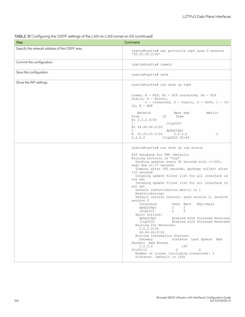
TABLE 31 Configuring the OSPF settings of the LNS-to-LNS tunnel on R2 (continued)
Step Command
Specify the network address of the OSPF area. vyatta@vyatta# set protocols ospf area 0 network '55.55.55.0/24'
Commit the configuration. vyatta@vyatta# commit
Save the configuration. vyatta@vyatta# save
Show the RIP settings. vyatta@vyatta# run show ip ospf
Codes: R - RIP, Rc - RIP connected, Rs - RIP static, K - Kernel, C - Connected, S - Static, O - OSPF, I - IS-IS, B - BGP
Network Next Hop Metric From If TimeRc 2.2.2.0/29 1 lttp2222Rc 44.44.44.0/24 1 dp0p224p1R 55.55.55.0/24 2.2.2.2 2 2.2.2.2 lttp2222 02:40
vyatta@vyatta# run show ip rip status
RIP Database for VRF (default)Routing Protocol is "rip" Sending updates every 30 seconds with +/-50%, next due in 17 seconds Timeout after 180 seconds, garbage collect after 120 seconds Outgoing update filter list for all interface is not set Incoming update filter list for all interface is not set Default redistribution metric is 1 Redistributing: Default version control: send version 2, receive version 2 Interface Send Recv Key-chain dp0p224p1 2 2 lttp2222 2 2 Split horizon: dp0p224p1 Enabled with Poisoned Reversed lttp2222 Enabled with Poisoned Reversed Routing for Networks: 2.2.2.0/29 44.44.44.0/24 Routing Information Sources: Gateway Distance Last Update Bad Packets Bad Routes 2.2.2.2 120 00:00:12 0 0 Number of routes (including connected): 3 Distance: (default is 120)
L2TPv3 Data Plane Interfaces
Brocade 5600 vRouter LAN Interfaces Configuration Guide194 53-1004259-01
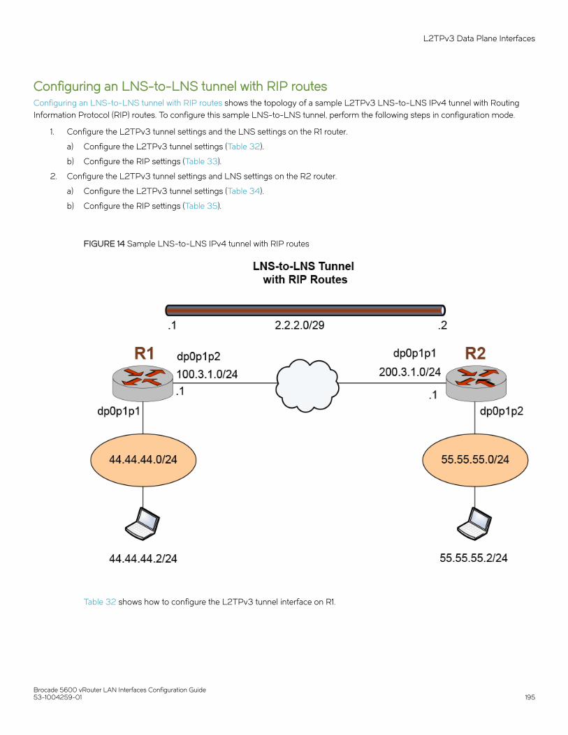
Configuring an LNS-to-LNS tunnel with RIP routesConfiguring an LNS-to-LNS tunnel with RIP routes shows the topology of a sample L2TPv3 LNS-to-LNS IPv4 tunnel with RoutingInformation Protocol (RIP) routes. To configure this sample LNS-to-LNS tunnel, perform the following steps in configuration mode.
1. Configure the L2TPv3 tunnel settings and the LNS settings on the R1 router.
a) Configure the L2TPv3 tunnel settings (Table 32).
b) Configure the RIP settings (Table 33).
2. Configure the L2TPv3 tunnel settings and LNS settings on the R2 router.
a) Configure the L2TPv3 tunnel settings (Table 34).
b) Configure the RIP settings (Table 35).
FIGURE 14 Sample LNS-to-LNS IPv4 tunnel with RIP routes
Table 32 shows how to configure the L2TPv3 tunnel interface on R1.
L2TPv3 Data Plane Interfaces
Brocade 5600 vRouter LAN Interfaces Configuration Guide53-1004259-01 195
TABLE 32 Configuring the L2TPv3 tunnel settings on R1
Step Command
Specify IP as the encapsulation method to use for the lttp1111 L2TPv3tunnel interface.
vyatta@vyatta# set interfaces l2tpeth lttp1111 l2tp-session encapsulation 'ip'
Specify the local IP address of the lttp1111 L2TPv3 tunnel interface. vyatta@vyatta# set interfaces l2tpeth lttp1111 l2tp-session local-ip '100.3.1.1'
Specify the local session identifier of the lttp1111 L2TPv3 tunnel interface. vyatta@vyatta# set interfaces l2tpeth lttp1111 l2tp-session local-session-id '40000000000'
Specify the remote IP address of the lttp1111 L2TPv3 tunnel interface. vyatta@vyatta# set interfaces l2tpeth lttp1111 l2tp-session remote-ip '200.3.1.1'
Specify the remote session identifier of the lttp1111 L2TPv3 tunnelinterface.
vyatta@vyatta# set interfaces l2tpeth lttp1111 l2tp-session remote-session-id '4000000000'
Specify the IP address of the tunnel interface to which the R1 router isconnected.
vyatta@vyatta# set interfaces l2tpeth lttp1111 address '2.2.2.1/29'
Specify IP as the encapsulation method to use for the lttp2222 L2TPv3tunnel interface.
vyatta@vyatta# set interfaces l2tpeth lttp2222 l2tp-session encapsulation 'ip'
Specify the local IP address of the lttp2222 L2TPv3 tunnel interface. vyatta@vyatta# set interfaces l2tpeth lttp2222 l2tp-session local-ip '100.3.1.1'
Specify the local session identifier of the lttp2222 L2TPv3 tunnelinterface.
vyatta@vyatta# set interfaces l2tpeth lttp2222 l2tp-session local-session-id '40000000000'
Specify the remote IP address of the lttp2222 L2TPv3 tunnel interface. vyatta@vyatta# set interfaces l2tpeth lttp2222 l2tp-session remote-ip '200.3.1.1'
Specify the remote session identifier of the lttp2222 L2TPv3 tunnelinterface.
vyatta@vyatta# set interfaces l2tpeth lttp2222 l2tp-session remote-session-id '4000000000'
Specify the IP address of R1 (the local router). vyatta@vyatta# set interfaces l2tpeth lttp2222 address '2.2.2.2/29'
Commit the configuration. vyatta@vyatta# commit
Save the configuration. vyatta@vyatta# save
Table 33 shows how to configure the RIP settings for the tunnel on R1. For more information about configuring thesesettings, refer to RIP Installing and Upgrading.
TABLE 33 Configuring the BGP settings of the LNS-to-LNS tunnel on R1
Step Command
Specify a network for RIP. vyatta@vyatta# set protocols rip network '2.2.2.0/29'
L2TPv3 Data Plane Interfaces
Brocade 5600 vRouter LAN Interfaces Configuration Guide196 53-1004259-01
TABLE 33 Configuring the BGP settings of the LNS-to-LNS tunnel on R1 (continued)
Step Command
Specify a network for RIP. vyatta@vyatta# set protocols rip network '44.44.44.0/24'
Commit the configuration. vyatta@vyatta# commit
Save the configuration. vyatta@vyatta# save
Exit the configuration mode. vyatta@vyatta# exit
Show the configuration information for the lttp2222 interface. vyatta@vyatta:~$ show interfaces l2tpeth lttp2222
address 2.2.2.1/29l2tp-session { encapsulation ip local-ip 100.3.1.1 local-session-id 2000000 remote-ip 200.3.1.1 remote-session-id 2000000}
Show the configured RIP protocols. vyatta@vyatta:~$ show protocols rip
rip { network 2.2.2.0/29 network 44.44.44.0/24 }
Table 34 shows how to configure the L2TPv3 tunnel interface on R2.
TABLE 34 Configuring the L2TPv3 tunnel interface settings on R2
Step Command
Specify IP as the encapsulation method to use for the lttp1111 L2TPv3tunnel interface.
vyatta@vyatta# set interfaces l2tpeth lttp1111 l2tp-session encapsulation 'ip'
Specify the local IP address of the lttp1111 L2TPv3 tunnel interface. vyatta@vyatta# set interfaces l2tpeth lttp1111 l2tp-session local-ip '200.3.1.1'
Specify the local session identifier of the lttp1111 L2TPv3 tunnel interface. vyatta@vyatta# set interfaces l2tpeth lttp1111 l2tp-session local-session-id '40000000000'
Specify the remote IP address of the lttp1111 L2TPv3 tunnel interface. vyatta@vyatta# set interfaces l2tpeth lttp1111 l2tp-session remote-ip '100.3.1.1'
Specify the remote session identifier of the lttp1111 L2TPv3 tunnelinterface.
vyatta@vyatta# set interfaces l2tpeth lttp1111 l2tp-session remote-session-id '4000000000'
Specify the IP address of the tunnel interface to which the router isconnected.
vyatta@vyatta# set interfaces l2tpeth lttp1111 address '1.1.1.2/24'
Specify IP as the encapsulation method to use for the lttp2222 L2TPv3tunnel interface.
vyatta@vyatta# set interfaces l2tpeth lttp2222 l2tp-session encapsulation 'ip'
L2TPv3 Data Plane Interfaces
Brocade 5600 vRouter LAN Interfaces Configuration Guide53-1004259-01 197
TABLE 34 Configuring the L2TPv3 tunnel interface settings on R2 (continued)
Step Command
Specify the local IP address of the lttp2222 L2TPv3 tunnel interface. vyatta@vyatta# set interfaces l2tpeth lttp2222 l2tp-session local-ip '200.3.1.1'
Specify the local session identifier of the lttp2222 L2TPv3 tunnelinterface.
vyatta@vyatta# set interfaces l2tpeth lttp2222 l2tp-session local-session-id '40000000000'
Specify the remote IP address of the lttp2222 L2TPv3 tunnel interface. vyatta@vyatta# set interfaces l2tpeth lttp2222 l2tp-session remote-ip '100.3.1.1'
Specify the IP address of the tunnel interface to which the router isconnected.
vyatta@vyatta# set interfaces l2tpeth lttp2222 address '2.2.2.2/29'
Specify the remote session identifier of the lttp2222 L2TPv3 tunnelinterface.
vyatta@vyatta# set interfaces l2tpeth lttp2222 l2tp-session remote-session-id '4000000000'
Commit the configuration. vyatta@vyatta# commit
Save the configuration. vyatta@vyatta# save
Table 35 shows how to configure the RIP settings for the tunnel on R2. For more information about configuring thesesettings, refer to RIP Installing and Upgrading.
TABLE 35 Configuring the RIP settings of the LNS-to-LNS tunnel on R2
Step Command
Specify a network for RIP. vyatta@vyatta# set protocols rip network '2.2.2.0/29'
Specify a network for RIP. vyatta@vyatta# set protocols rip network '55.55.55.0/24'
Commit the configuration. vyatta@vyatta# commit
Save the configuration. save
L2TPv3 Data Plane Interfaces
Brocade 5600 vRouter LAN Interfaces Configuration Guide198 53-1004259-01
L2TPv3 Data Plane Interfaces Commands∙ interfaces l2tpeth <lttpN> l2tp-session encapsulation <encapsulation-method>.....................................................................200∙ interfaces l2tpeth <lttpN> l2tp-session local-cookie <cookie-string>............................................................................................... 201∙ interfaces l2tpeth <lttpN> l2tp-session local-ip <local-ip-address>.................................................................................................202∙ interfaces l2tpeth <lttpN> l2tp-session local-session-id <id>.............................................................................................................. 203∙ interfaces l2tpeth <lttpN> l2tp-session local-udp-port <udp-port>..................................................................................................204∙ interfaces l2tpeth <lttpN> l2tp-session remote-cookie <cookie-string>........................................................................................205∙ interfaces l2tpeth <lttpN> l2tp-session remote-ip <remote-ip-address>..................................................................................... 206∙ interfaces l2tpeth <lttpN> l2tp-session remote-session-id <id>.........................................................................................................207∙ interfaces l2tpeth <lttpN> l2tp-session remote-udp-port <udp-port>............................................................................................208∙ interfaces dataplane <interface-name> xconnect l2tpeth <tunnel-interface-name>...............................................................209∙ interfaces dataplane <interface-name> vif <id> xconnect l2tpeth <tunnel-interface-name>................................................210∙ show interfaces <lttpN>.................................................................................................................................................................................................. 211∙ show l2tpeth....................................................................................................................................................................................................................... 212∙ show l2tpeth <lttpN>...................................................................................................................................................................................................... 213
Brocade 5600 vRouter LAN Interfaces Configuration Guide53-1004259-01 199
interfaces l2tpeth <lttpN> l2tp-session encapsulation <encapsulation-method>
Specifies either IP or UDP as the encapsulation method to use for an L2TPv3 tunnel interface.
Syntaxset interfaces l2tpeth lttpN l2tp-session encapsulation encapsulation-method
delete interfaces l2tpeth lttpN l2tp-session encapsulation encapsulation-method
ParameterslttpN
L2TPv3 static L2TPv3 tunnel interface. The interface ranges from lttp0 through lttpN, where N is a non-negativeinteger.
encapsulation-methodEncapsulation method (IP or UDP) to use for the interface.
ModesConfiguration mode
Configuration Statementinterfaces { l2tpeth lttpN { l2tp-session { encapsulation encapsulation-method } }}
Usage GuidelinesUse the set form of this command to specify either IP or UDP as the encapsulation method to use for an L2TPv3 interface.
Use the delete form of this command to remove the encapsulation method from an L2TPv3 tunnel interface.
L2TPv3 Data Plane Interfaces Commands
Brocade 5600 vRouter LAN Interfaces Configuration Guide200 53-1004259-01
interfaces l2tpeth <lttpN> l2tp-session local-cookie <cookie-string>Specifies a local cookie string.
Syntaxset interfaces l2tpeth lttpN l2tp-session local-cookie cookie-string
delete interfaces l2tpeth lttpN l2tp-session local-cookie cookie-string
ParameterslttpN
L2TPv3 static L2TPv3 tunnel interface. The interface ranges from lttp0 through lttpN, where N is a non-negativeinteger.
cookie-stringCookie string. An 8- or 16-byte hexadecimal string (for example, abcdef01).
ModesConfiguration mode
Configuration Statementinterfaces { l2tpeth lttpN { l2tp-session { local-cookie cookie-string } }}
Usage GuidelinesUse the set form of this command to specify a local cookie string.
Use the delete form of this command to remove a local cookie string.
L2TPv3 Data Plane Interfaces Commands
Brocade 5600 vRouter LAN Interfaces Configuration Guide53-1004259-01 201
interfaces l2tpeth <lttpN> l2tp-session local-ip <local-ip-address>Specifies a local IP address of an L2TPv3 tunnel interface.
Syntaxset interfaces l2tpeth lttpN l2tp-session local-ip local-ip-address
delete interfaces l2tpeth lttpN l2tp-session local-ip local-ip-address
ParameterslttpN
L2TPv3 static L2TPv3 tunnel interface. The interface ranges from lttp0 through lttpN, where N is a non-negativeinteger.
local-ip-addressIPv4 or IPv6 local IP address of the tunnel interface.
ModesConfiguration mode
Configuration Statementinterfaces { l2tpeth lttpN { l2tp-session { local-ip local-ip-address } }}
Usage GuidelinesUse the set form of this command to specify a local IP address of an L2TPv3 tunnel interface.
Use the delete form of this command to remove a local IP address from an L2TPv3 tunnel interface.
L2TPv3 Data Plane Interfaces Commands
Brocade 5600 vRouter LAN Interfaces Configuration Guide202 53-1004259-01
interfaces l2tpeth <lttpN> l2tp-session local-session-id <id>Specifies a local session identifier of an L2TPv3 tunnel interface.
Syntaxset interfaces l2tpeth lttpN l2tp-session local-session-id id
delete interfaces l2tpeth lttpN l2tp-session local-session-id id
ParameterslttpN
L2TPv3 static L2TPv3 tunnel interface. The interface ranges from lttp0 through lttpN, where N is a non-negativeinteger.
idLocal session identifier of the interface. The identifier ranges from 0 through 4294967295.
ModesConfiguration mode
Configuration Statementinterfaces { l2tpeth lttpN { l2tp-session { local-session-id id } }}
Usage GuidelinesUse the set form of this command to specify a local session identifier of an L2TPv3 tunnel interface.
Use the delete form of this command to remove a local session identifier from an L2TPv3 tunnel interface.
L2TPv3 Data Plane Interfaces Commands
Brocade 5600 vRouter LAN Interfaces Configuration Guide53-1004259-01 203
interfaces l2tpeth <lttpN> l2tp-session local-udp-port <udp-port>Specifies a local UDP port of an L2TPv3 tunnel interface.
Syntaxset interfaces l2tpeth lttpN l2tp-session local-udp-port udp-port
delete interfaces l2tpeth lttpN l2tp-session local-udp-port udp-port
ParameterslttpN
L2TPv3 static L2TPv3 tunnel interface. The interface ranges from lttp0 through lttpN, where N is a non-negativeinteger.
udp-portLocal UDP port for the tunnel interface. The port ranges from 1 through 65535.
ModesConfiguration mode
Configuration Statementinterfaces { l2tpeth lttpN { l2tp-session { local-udp-port udp-port } }}
Usage GuidelinesUse the set form of this command to specify a local UDP port of an L2TPv3 tunnel interface.
Use the delete form of this command to remove a local UDP port from an L2TPv3 tunnel interface.
L2TPv3 Data Plane Interfaces Commands
Brocade 5600 vRouter LAN Interfaces Configuration Guide204 53-1004259-01

interfaces l2tpeth <lttpN> l2tp-session remote-cookie <cookie-string>Specifies a remote cookie string.
Syntaxset interfaces l2tpeth lttpN l2tp-session remote-cookie cookie-string
delete interfaces l2tpeth lttpN l2tp-session remote-cookie cookie-string
ParameterslttpN
L2TPv3 static L2TPv3 tunnel interface. The interface ranges from lttp0 through lttpN, where N is a non-negativeinteger.
cookie-stringCookie string. An 8- or 16-byte hexadecimal string (for example, abcdef01).
ModesConfiguration mode
Configuration Statementinterfaces { l2tpeth lttpN { l2tp-session { remote-cookie cookie-string } }}
Usage GuidelinesUse the set form of this command to specify a remote cookie string.
Use the delete form of this command to remove a remote cookie string.
L2TPv3 Data Plane Interfaces Commands
Brocade 5600 vRouter LAN Interfaces Configuration Guide53-1004259-01 205
interfaces l2tpeth <lttpN> l2tp-session remote-ip <remote-ip-address>Specifies a remote IP address of an L2TPv3 tunnel interface.
Syntaxset interfaces l2tpeth lttpN l2tp-session remote-ip remote-ip-address
delete interfaces l2tpeth lttpN l2tp-session remote-ip remote-ip-address
ParameterslttpN
L2TPv3 static L2TPv3 tunnel interface. The interface ranges from lttp0 through lttpN, where N is a non-negativeinteger.
remote-ip-addressEncapsulation method (IP or UDP) to use for the interface.
ModesConfiguration mode
Configuration Statementinterfaces { l2tpeth lttpN { l2tp-session { remote-ip remote-ip-address } }}
Usage GuidelinesUse the set form of this command to specify a remote IP address of an L2TPv3 tunnel interface.
Use the delete form of this command to remove a remote IP address from an L2TPv3 tunnel interface.
L2TPv3 Data Plane Interfaces Commands
Brocade 5600 vRouter LAN Interfaces Configuration Guide206 53-1004259-01
interfaces l2tpeth <lttpN> l2tp-session remote-session-id <id>Specifies a remote session identifier of an L2TPv3 tunnel interface.
Syntaxset interfaces l2tpeth lttpN l2tp-session remote-session-id id
delete interfaces l2tpeth lttpN l2tp-session remote-session-id id
ParameterslttpN
L2TPv3 static L2TPv3 tunnel interface. The interface ranges from lttp0 through lttpN, where N is a non-negativeinteger.
idRemote session identifier of the interface. The identifier ranges from 0 through 4294967295.
ModesConfiguration mode
Configuration Statementinterfaces { l2tpeth lttpN { l2tp-session { remote-session-id id } }}
Usage GuidelinesUse the set form of this command to specify a remote session identifier of an L2TPv3 tunnel interface.
Use the delete form of this command to remove a remote session identifier from an L2TPv3 tunnel interface.
L2TPv3 Data Plane Interfaces Commands
Brocade 5600 vRouter LAN Interfaces Configuration Guide53-1004259-01 207
interfaces l2tpeth <lttpN> l2tp-session remote-udp-port <udp-port>Specifies a remote UDP port of a tunnel interface.
Syntaxset interfaces l2tpeth lttpN l2tp-session remote-udp-port udp-port
delete interfaces l2tpeth lttpN l2tp-session remote-udp-port udp-port
ParameterslttpN
L2TPv3 static L2TPv3 tunnel interface. The interface ranges from lttp0 through lttpN, where N is a non-negativeinteger.
udp-portRemote UDP port of the interface. The port ranges from 1 through 65535.
ModesConfiguration mode
Configuration Statementinterfaces { l2tpeth lttpN { l2tp-session { remote-udp-port udp-port } }}
Usage GuidelinesUse the set form of this command to specify a remote UDP port of an L2TPv3 tunnel interface.
Use the delete form of this command to remove a remote UDP port from an L2TPv3 tunnel interface.
L2TPv3 Data Plane Interfaces Commands
Brocade 5600 vRouter LAN Interfaces Configuration Guide208 53-1004259-01
interfaces dataplane <interface-name> xconnect l2tpeth <tunnel-interface-name>
Specifies the cross-connect parameters of an L2TPv3 tunnel interface.
Syntaxset interfaces dataplane interface-name xconnect l2tpeth tunnel-interface-name
delete interfaces dataplane interface-name xconnect l2tpeth tunnel-interface-name
Parametersinterface-name
The name of a data plane interface. For more information about the supported interface name formats, refer to DataPlane Interface on page 215.
tunnel-interface-nameL2TPv3 tunnel interface name.
ModesConfiguration mode
Configuration Statementinterfaces { dataplane interface-name { xconnect { l2tpeth tunnel-interface-name } }}
Usage GuidelinesUse the set form of this command to specify the cross-connect parameters of an L2TPv3 tunnel interface.
Use the delete form of this command to remove the cross-connect parameters of an L2TPv3 tunnel interface.
L2TPv3 Data Plane Interfaces Commands
Brocade 5600 vRouter LAN Interfaces Configuration Guide53-1004259-01 209
interfaces dataplane <interface-name> vif <id> xconnect l2tpeth <tunnel-interface-name>
Specifies a virtual interface (VIF) identifier and the cross-connect parameters of an L2TPv3 tunnel interface.
Syntaxset interfaces dataplane interface-name vif id xconnect l2tpeth tunnel-interface-name
delete interfaces dataplane interface-name vif id xconnect l2tpeth tunnel-interface-name
Parametersinterface-name
Data plane interface to which the L2TPv3 tunnel is connected.The name of a data plane interface. For more information about the supported interface name formats, refer to DataPlane Interface on page 215.
idVirtual interface identifier. The identifier ranges from 1 through 4094.
tunnel-interface-nameL2TPv3 tunnel interface name.
ModesConfiguration mode
Configuration Statementinterfaces { dataplane interface-name { vif id { xconnect { l2tpeth tunnel-interface-name } } }}
Usage GuidelinesUse the set form of this command to specify a VIF identifier and the cross-connect parameters of an L2TPv3 tunnel interface.
Use the delete form of this command to remove a VIF identifier and the cross-connect parameters of an L2TPv3 tunnelinterface.
L2TPv3 Data Plane Interfaces Commands
Brocade 5600 vRouter LAN Interfaces Configuration Guide210 53-1004259-01
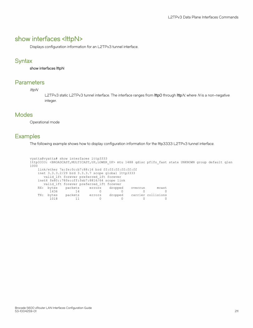
show interfaces <lttpN>Displays configuration information for an L2TPv3 tunnel interface.
Syntaxshow interfaces lttpN
ParameterslttpN
L2TPv3 static L2TPv3 tunnel interface. The interface ranges from lttp0 through lttpN, where N is a non-negativeinteger.
ModesOperational mode
ExamplesThe following example shows how to display configuration information for the lttp3333 L2TPv3 tunnel interface.
vyatta@vyatta# show interfaces lttp3333lttp3333: <BROADCAST,MULTICAST,UP,LOWER_UP> mtu 1488 qdisc pfifo_fast state UNKNOWN group default qlen 1000 link/ether 7a:fe:0c:b7:88:16 brd ff:ff:ff:ff:ff:ff inet 3.3.3.2/29 brd 3.3.3.7 scope global lttp3333 valid_lft forever preferred_lft forever inet6 fe80::78fe:cff:feb7:8816/64 scope link valid_lft forever preferred_lft forever RX: bytes packets errors dropped overrun mcast 1436 14 0 0 0 0 TX: bytes packets errors dropped carrier collisions 1018 11 0 0 0 0
L2TPv3 Data Plane Interfaces Commands
Brocade 5600 vRouter LAN Interfaces Configuration Guide53-1004259-01 211
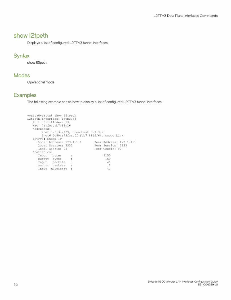
show l2tpethDisplays a list of configured L2TPv3 tunnel interfaces.
Syntaxshow l2tpeth
ModesOperational mode
ExamplesThe following example shows how to display a list of configured L2TPv3 tunnel interfaces.
vyatta@vyatta# show l2tpethL2tpeth interface: lttp3333 Port: 0, ifIndex: 13 Mac: 7a:fe:c:b7:88:16 Addresses: inet 3.3.3.2/29, broadcast 3.3.3.7 inet6 fe80::78fe:cff:feb7:8816/64, scope Link L2TPv3: Encap IP Local Address: 173.1.1.1 Peer Address: 172.1.1.1 Local Session: 3333 Peer Session: 3333 Local Cookie: 00 Peer Cookie: 00 Statistics: Input bytes : 4150 Output bytes : 160 Input packets : 41 Output packets : 2 Input multicast : 41
L2TPv3 Data Plane Interfaces Commands
Brocade 5600 vRouter LAN Interfaces Configuration Guide212 53-1004259-01
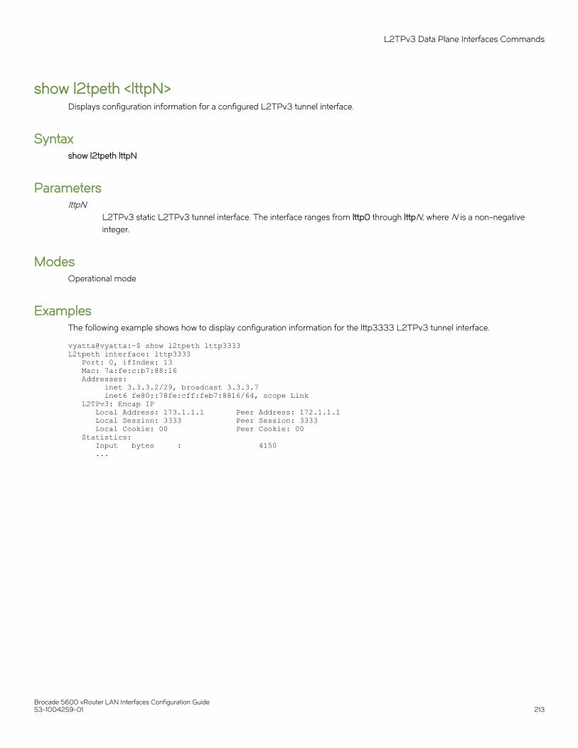
show l2tpeth <lttpN>Displays configuration information for a configured L2TPv3 tunnel interface.
Syntaxshow l2tpeth lttpN
ParameterslttpN
L2TPv3 static L2TPv3 tunnel interface. The interface ranges from lttp0 through lttpN, where N is a non-negativeinteger.
ModesOperational mode
ExamplesThe following example shows how to display configuration information for the lttp3333 L2TPv3 tunnel interface.
vyatta@vyatta:~$ show l2tpeth lttp3333L2tpeth interface: lttp3333 Port: 0, ifIndex: 13 Mac: 7a:fe:c:b7:88:16 Addresses: inet 3.3.3.2/29, broadcast 3.3.3.7 inet6 fe80::78fe:cff:feb7:8816/64, scope Link L2TPv3: Encap IP Local Address: 173.1.1.1 Peer Address: 172.1.1.1 Local Session: 3333 Peer Session: 3333 Local Cookie: 00 Peer Cookie: 00 Statistics: Input bytes : 4150 ...
L2TPv3 Data Plane Interfaces Commands
Brocade 5600 vRouter LAN Interfaces Configuration Guide53-1004259-01 213

L2TPv3 Data Plane Interfaces Commands
Brocade 5600 vRouter LAN Interfaces Configuration Guide214 53-1004259-01
Data Plane InterfaceThe name of a data plane interface. Following are the supported formats of the interface name:
∙ dpxpypz—The name of a data plane interface, where
— dpx specifies the data plane identifier (ID). Currently, only dp0 is supported.
— py specifies a physical or virtual PCI slot index (for example, p129).
— pz specifies a port index (for example, p1). For example, dp0p1p2, dp0p160p1, and dp0p192p1.
∙ dpxemy —The name of a data plane interface on a LAN-on-motherboard (LOM) device that does not have a PCI slot, whereemy specifies an embedded network interface number (typically, a small number). For example, dp0em3.
∙ dpxsy —The name of a data plane interface on a device that is installed on a virtual PCI slot, where xsy specifies an embeddednetwork interface number (typically, a small number). For example, dp0s2.
∙ dpxPnpypz —The name of a data plane interface on a device that is installed on a secondary PCI bus, where Pn specifies thebus number. You can use this format to name data plane interfaces on large physical devices with multiple PCI buses. For thesedevices, it is possible to have network interface cards installed on different buses with these cards having the same slot ID. Thevalue of n must be an integer greater than 0. For example, dp0P1p162p1 and dp0P2p162p1.
Brocade 5600 vRouter LAN Interfaces Configuration Guide53-1004259-01 215

Data Plane Interface
Brocade 5600 vRouter LAN Interfaces Configuration Guide216 53-1004259-01
List of Acronyms
Acronym Description
ACL access control list
ADSL Asymmetric Digital Subscriber Line
AH Authentication Header
AMI Amazon Machine Image
API Application Programming Interface
AS autonomous system
ARP Address Resolution Protocol
AWS Amazon Web Services
BGP Border Gateway Protocol
BIOS Basic Input Output System
BPDU Bridge Protocol Data Unit
CA certificate authority
CCMP AES in counter mode with CBC-MAC
CHAP Challenge Handshake Authentication Protocol
CLI command-line interface
DDNS dynamic DNS
DHCP Dynamic Host Configuration Protocol
DHCPv6 Dynamic Host Configuration Protocol version 6
DLCI data-link connection identifier
DMI desktop management interface
DMVPN dynamic multipoint VPN
DMZ demilitarized zone
DN distinguished name
DNS Domain Name System
DSCP Differentiated Services Code Point
DSL Digital Subscriber Line
eBGP external BGP
EBS Amazon Elastic Block Storage
EC2 Amazon Elastic Compute Cloud
EGP Exterior Gateway Protocol
ECMP equal-cost multipath
ESP Encapsulating Security Payload
FIB Forwarding Information Base
FTP File Transfer Protocol
GRE Generic Routing Encapsulation
HDLC High-Level Data Link Control
I/O Input/Output
ICMP Internet Control Message Protocol
Brocade 5600 vRouter LAN Interfaces Configuration Guide53-1004259-01 217
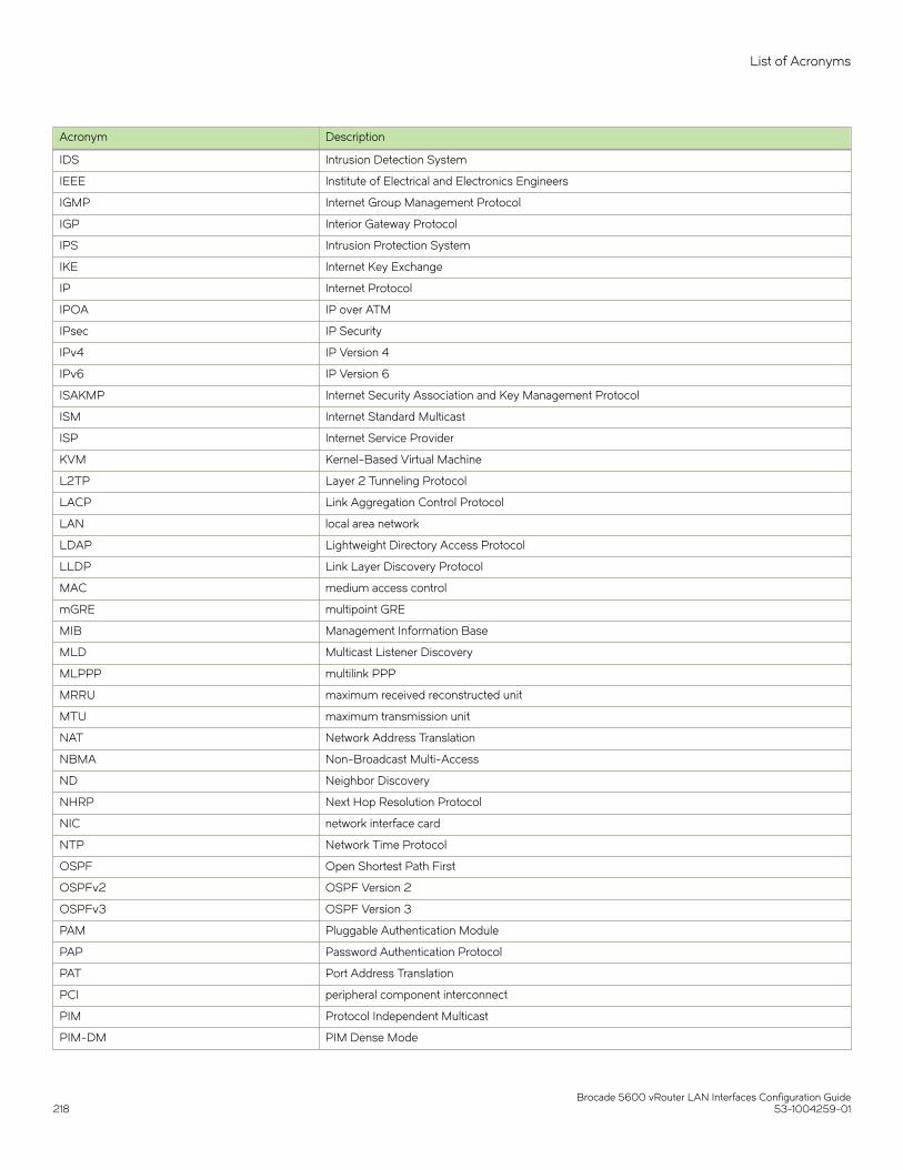
Acronym Description
IDS Intrusion Detection System
IEEE Institute of Electrical and Electronics Engineers
IGMP Internet Group Management Protocol
IGP Interior Gateway Protocol
IPS Intrusion Protection System
IKE Internet Key Exchange
IP Internet Protocol
IPOA IP over ATM
IPsec IP Security
IPv4 IP Version 4
IPv6 IP Version 6
ISAKMP Internet Security Association and Key Management Protocol
ISM Internet Standard Multicast
ISP Internet Service Provider
KVM Kernel-Based Virtual Machine
L2TP Layer 2 Tunneling Protocol
LACP Link Aggregation Control Protocol
LAN local area network
LDAP Lightweight Directory Access Protocol
LLDP Link Layer Discovery Protocol
MAC medium access control
mGRE multipoint GRE
MIB Management Information Base
MLD Multicast Listener Discovery
MLPPP multilink PPP
MRRU maximum received reconstructed unit
MTU maximum transmission unit
NAT Network Address Translation
NBMA Non-Broadcast Multi-Access
ND Neighbor Discovery
NHRP Next Hop Resolution Protocol
NIC network interface card
NTP Network Time Protocol
OSPF Open Shortest Path First
OSPFv2 OSPF Version 2
OSPFv3 OSPF Version 3
PAM Pluggable Authentication Module
PAP Password Authentication Protocol
PAT Port Address Translation
PCI peripheral component interconnect
PIM Protocol Independent Multicast
PIM-DM PIM Dense Mode
List of Acronyms
Brocade 5600 vRouter LAN Interfaces Configuration Guide218 53-1004259-01
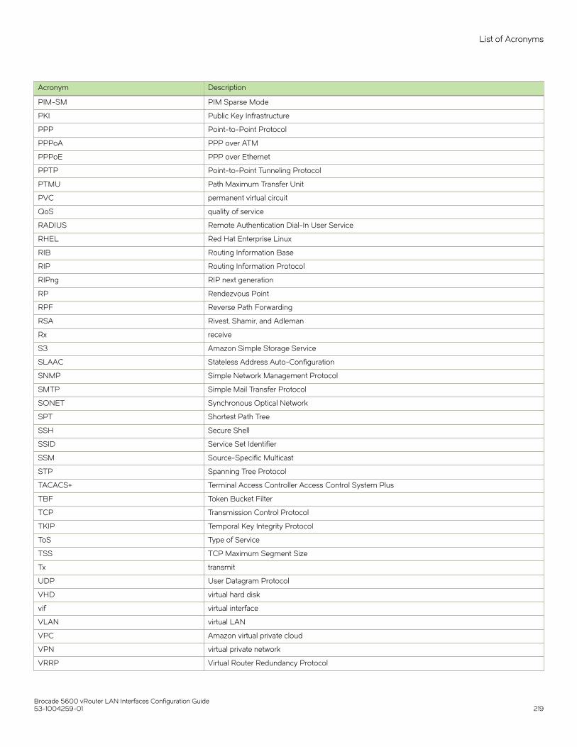
Acronym Description
PIM-SM PIM Sparse Mode
PKI Public Key Infrastructure
PPP Point-to-Point Protocol
PPPoA PPP over ATM
PPPoE PPP over Ethernet
PPTP Point-to-Point Tunneling Protocol
PTMU Path Maximum Transfer Unit
PVC permanent virtual circuit
QoS quality of service
RADIUS Remote Authentication Dial-In User Service
RHEL Red Hat Enterprise Linux
RIB Routing Information Base
RIP Routing Information Protocol
RIPng RIP next generation
RP Rendezvous Point
RPF Reverse Path Forwarding
RSA Rivest, Shamir, and Adleman
Rx receive
S3 Amazon Simple Storage Service
SLAAC Stateless Address Auto-Configuration
SNMP Simple Network Management Protocol
SMTP Simple Mail Transfer Protocol
SONET Synchronous Optical Network
SPT Shortest Path Tree
SSH Secure Shell
SSID Service Set Identifier
SSM Source-Specific Multicast
STP Spanning Tree Protocol
TACACS+ Terminal Access Controller Access Control System Plus
TBF Token Bucket Filter
TCP Transmission Control Protocol
TKIP Temporal Key Integrity Protocol
ToS Type of Service
TSS TCP Maximum Segment Size
Tx transmit
UDP User Datagram Protocol
VHD virtual hard disk
vif virtual interface
VLAN virtual LAN
VPC Amazon virtual private cloud
VPN virtual private network
VRRP Virtual Router Redundancy Protocol
List of Acronyms
Brocade 5600 vRouter LAN Interfaces Configuration Guide53-1004259-01 219

Acronym Description
WAN wide area network
WAP wireless access point
WPA Wired Protected Access
List of Acronyms
Brocade 5600 vRouter LAN Interfaces Configuration Guide220 53-1004259-01


![Brocade 5600 vRouter Firewall Configuration …...Convention Description... Repeat the previous element, for example, member[member...]. \ Indicates a “soft” line break in command](https://cdn.vdocuments.us/doc/165x107/5e783e465cb67338c676e2ac/brocade-5600-vrouter-firewall-configuration-convention-description-repeat.jpg)


