BERKELEY®
care manualw w w.BERKELEYPUMPS.coM
R J19L M ON OFF
H 806H 806
2
Table of conTenTs
This Care Manual was designed as a general guide to Berkeley centrifugal pumps and is not intended to be used as an Engineering Specifications Manual.
All subjects covered, whether written or illustrated, are suggestions by Berkeley Pumps to aid in the proper installation and operation of end suction centrifugal pumps and apply to no particular application.
Questions on specific application and/or installation procedures, maintenance, and repair, should be directed to the nearest Berkeley Professional Dealer.
Component damage can occur when excessive force is applied during assembly, disassembly, repair, or maintenance. Generally, components do not need to be forced on or off during these procedures. Use care at all times to protect the physical integrity of all pump components.
Introduction 2 section 1: Installation 3-14 section 2: start-up 15-19 section 3: maintenance 20-28 section 4: Pump nomenclature 29-35
watch foR thiS SYMBoL
InTroducTIon
BERKELEY® caRE ManUaL
3
suction connection, suction lift – recommended 4 suction connection, suction lift – not recommended 5 suction connection, flooded suction – recommended 6 suction connection, flooded suction – not recommended 7 discharge connection – recommended 8 discharge connection – not recommended 9 Pump foundation 10 Pump Protection, Pump House / shelter 11 shaft alignment belt / coupling drive 12 Protect Your Investment 13,14
conTenTs
SEction 1 - inStaLLation
4
503 0194
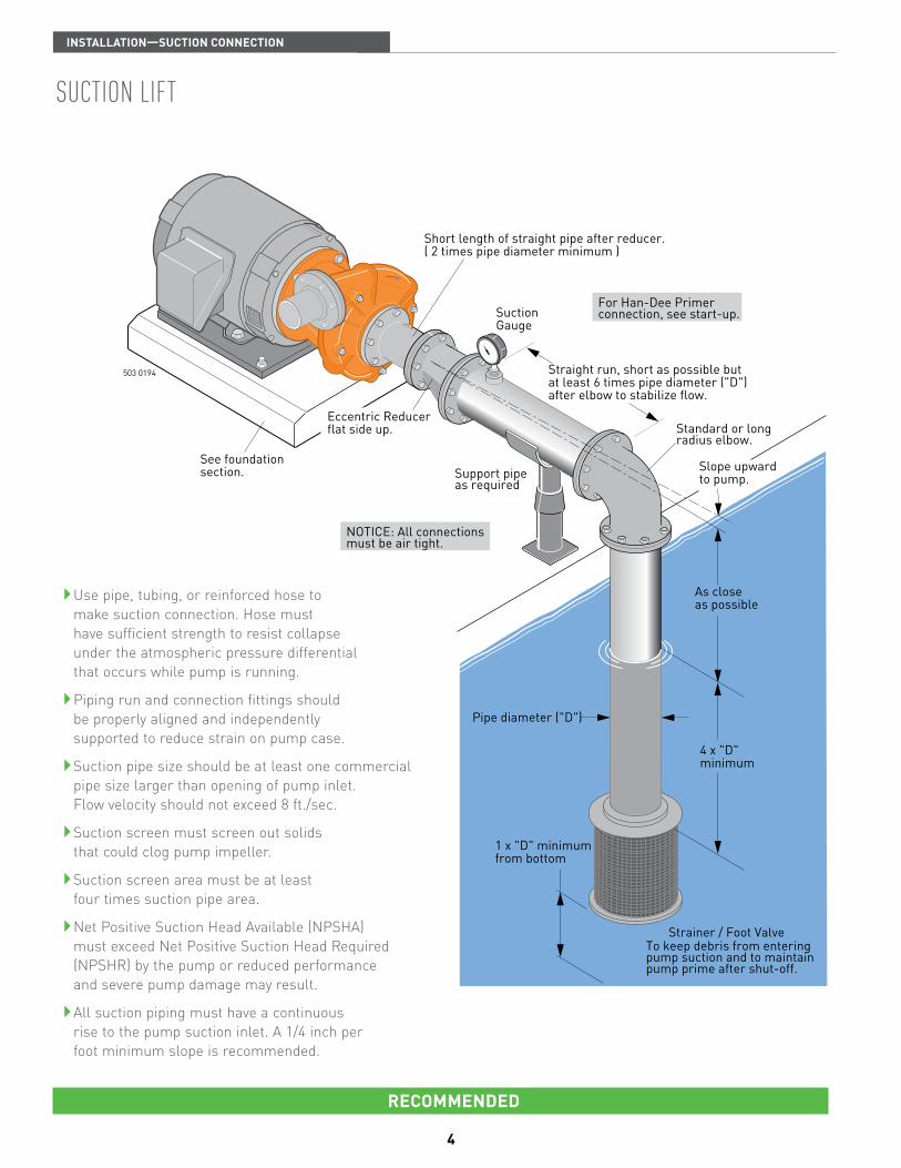
Short length of straight pipe after reducer.( 2 times pipe diameter minimum )
SuctionGauge
Straight run, short as possible but at least 6 times pipe diameter ("D")after elbow to stabilize flow.
As close as possible
Pipe diameter ("D")
4 x "D"minimum
1 x "D" minimumfrom bottom
Strainer / Foot ValveTo keep debris from enteringpump suction and to maintainpump prime after shut-off.
Eccentric Reducerflat side up.
See foundationsection. Support pipe
as required
NOTICE: All connectionsmust be air tight.
For Han-Dee Primerconnection, see start-up.
Standard or longradius elbow.
Slope upwardto pump.
REcoMMEndEd
Use pipe, tubing, or reinforced hose to make suction connection. Hose must have sufficient strength to resist collapse under the atmospheric pressure differential that occurs while pump is running.
Piping run and connection fittings should be properly aligned and independently supported to reduce strain on pump case.
Suction pipe size should be at least one commercial pipe size larger than opening of pump inlet. Flow velocity should not exceed 8 ft./sec.
Suction screen must screen out solids that could clog pump impeller.
Suction screen area must be at least four times suction pipe area.
Net Positive Suction Head Available (NPSHA) must exceed Net Positive Suction Head Required (NPSHR) by the pump or reduced performance and severe pump damage may result.
All suction piping must have a continuous rise to the pump suction inlet. A 1/4 inch per foot minimum slope is recommended.
sucTIon lIfT
inStaLLation—SUction connEction

5
505 0194
Do not useConcentricReducer. Concentric Reducer causes high spots
along the suction line resulting in air pockets.
Do not install valves in suction line.
Long run not recommended
Unsupportedpipe causesexcessive stress on pump and fittings.
Excess use of pipe fittingsmeans potential air leaks.
No support oruneven mountingnot recommended.
High suctionlift shouldbe avoided.
Less than4 x "D"
Vortex caused byinsufficient submergencemay cause pump tolose prime.
No strainermay causepump to clog.
Insufficient bottomclearance
Elbow immediately infront of pump intakenot recommended. Pipe diameter
("D") undersizedreduces performance
not REcoMMEndEd
Suction pipe sloping downward to pump inlet will trap air which will reduce performance and may cause pump to lose prime.
Suction piping that is undersized will create excess friction losses that may cause cavitation and a reduction in pump performance.
Excess fittings and bends in suction line results in trapped air, reduced performance, and high friction losses which may cause cavitation.
sucTIon lIfT
inStaLLation—SUction connEction

6
702 0294
Water underpressure
Support pipeas required
Short run of straight pipe after reducer(2 times pipe diameter).
Eccentric Reducerflat side up.
Maintain minimum liquidlevel to prevent vortexing.
Isolation Valvefull open whenpumping.
Standard orlong radiuselbow.
SuctionGauge
Straight run, short as possible but at least 6 times pipe diameter afterpipe fitting to stabilize flow.Slope upward to pump.
Use pipe, tubing, or reinforced hose to make suction connection. Hose must have sufficient strength to resist collapse under the atmospheric pressure differential that may occur while pump is running.
It is important, even with a flooded suction condition, that proper pipe fittings are used so water is delivered to impeller eye with a smooth flow and constant velocity.
Suction pipe size should be at least one commercial pipe size larger than opening of pump inlet. Flow velocity should not exceed 8 ft./sec.
An isolation valve is used in a pressurized suction pipe to permit servicing pump.
Piping run and connection fittings should be properly aligned and independently supported to reduce strain on pump case.
If solids are present, a strainer should be used to protect the pump.
REcoMMEndEd
wHen flooded sucTIon exIsTs
inStaLLation—SUction connEction
7
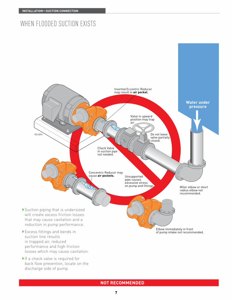
703 0294
Water underpressure
Inverted Eccentric Reducermay result in air pocket.
Do not leave valve partially closed.
Check Valvein suction pipenot needed.
Unsupportedpipe causesexcessive stresson pump and fittings.
Concentric Reducer maycause air pockets.
Elbow immediately in frontof pump intake not recommended.
Valve in upwardposition may trapair.
Miter elbow or shortradius elbow notrecommended.
Suction piping that is undersized will create excess friction losses that may cause cavitation and a reduction in pump performance.
Excess fittings and bends in suction line results in trapped air, reduced performance and high friction losses which may cause cavitation.
If a check valve is required for back flow prevention, locate on the discharge side of pump.
not REcoMMEndEd
wHen flooded sucTIon exIsTs
inStaLLation—SUction connEction

8
REcoMMEndEd
Expansion joint with tierods where needed.
Use Concentric Reducerto mimimize friction losses.
This fitting may be used tocheck shut-off head.
IsolationValve
Support pipingas required
This view shows dischargefittings typical of pumpwith flooded suction.
These two views show dischargefittings typical of pump withsuction lift.
Discharge pipe diameter atleast one nominal pipe sizelarger than discharge openingin pump.
Non-Slam orspring loadedcheck valve.
Isolation valve topermit servicing ofcheck valve or pump.
DischargePrimingValve
Align piping tominimize flangestress.
706 0294
PressureGauge
Use pipe, tubing, or reinforced hose to make discharge connection. Material selected must have sufficient strength for operating pressures.
Discharge pipe should be sized so that flow velocity is below 8 ft./sec.
Use only non-slamming check valves to prevent hydraulic shock (water hammer).
Use gate, ball, or butterfly valve for isolation. Valve should be full open during operation.
Maintain proper pipe size throughout discharge system, using as few elbows and tees as possible to keep friction loss to a minimum.
Install pressure gauge after reducer as shown to check operating pressure.
inStaLLation
dIscHarge connecTIon
9
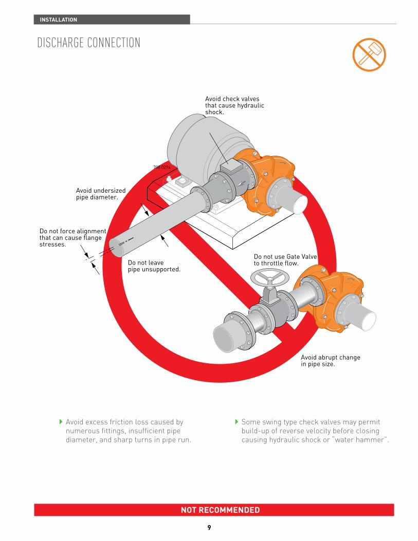
not REcoMMEndEd
Avoid excess friction loss caused by numerous fittings, insufficient pipe diameter, and sharp turns in pipe run.
Some swing type check valves may permit build-up of reverse velocity before closing causing hydraulic shock or “water hammer”.
Do not use Gate Valveto throttle flow.
Avoid abrupt changein pipe size.
708 0294
Avoid undersizedpipe diameter.
Do not force alignmentthat can cause flangestresses.
Do not leavepipe unsupported.
Avoid check valvesthat cause hydraulicshock.
inStaLLation
dIscHarge connecTIon

10
Drainage
Drainage
Pump or Motor Frame
1/2" or thickerSole Plate tapped
for hold down bolts
AnchorBolts
Concrete Foundation
Pump or Motor Frame
Shimsfor alignment
AnchorBoltSteel
Channel
ConcreteFoundation
GroutGroutDam
Drainage
WedgesVarious Heights
ConcreteFoundation
Shims
797 0394
TackWeld
There are several types of permanent pump/ foundation installations in use. Those pictured above are typical.
If grout is used, top of concrete should be left rough to provide a good bonding surface.
Foundation should slope away from pump to prevent liquid from pooling.
TYPIcal InsTallaTIons
inStaLLation—PUMP foUndation

11
To PumpSuction
To PumpDischarge
Provide proper supportfor all pipe runs.
From watersource
To waterservice
Large door(s)for installationand servicing
Forced air ventilationis recommended
Allow for properdrainage
934 0594
Removablefor service
Air Movement
935 0594
Check local codes for all electrical connections.
Check local codes for all plumbing connections.
Allow adequate room around pump for servicing.
Allow for water drainage inside pump house (floor drains).
Allow for heating capabilities if pump is running year round.
Pump shelter with removable roof protects pump from rain, dust, plants, and the sun. Locate shelter to avoid flooding.
Proper ventilation is a must.
Allow for proper drainage away from pump and motor.
Check local codes for all electrical connections.
Check local codes for all plumbing connections.
PumP House
inStaLLation—PUMP PRotEction
PumP sHelTer

12
936 0594
See standard or preferredmethod descibed below.
H 806H 806
Centerline
B.Perry
Caliper
Straight Edge
H 806H 806
Centerline
Centerline
A
A
BB
B
B
Incorrect
Centerline - A of each shaft and pulley mustbe parallel for proper alignment.
Incorrect
Centerline - B represents center of belt andpulley.This centerline must be straight forproper alignment.
937 0594
AA
Belt guard is not shown for pictorial clarity. never operate pump without proper guard or shroud in place.
For proper belt tension, check belt manufacturer’s specifications.
Standard Method: Use a caliper or straight edge to check for proper alignment. Check four places, 90 degrees apart.
Preferred Method: Use a commercially available dial indicator to check for proper alignment. Refer to coupling I.O.M. for detailed instruction.
Coupling guard shown in phantom for pictorial clarity. never operate pump without guard or shroud in place.
couPlIng alIgnmenT
inStaLLation—Shaft aLignMEnt
belT drIve
13
884 0494
1
2
3
AMP TIME
4
5
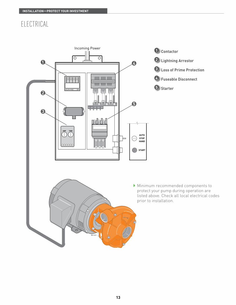
Incoming Power
L1 L2 L3
AUTOSTOPHAND
START
Minimum recommended components to protect your pump during operation are listed above. Check all local electrical codes prior to installation.
1 contactor
2 Lightning arrestor
3 Loss of Prime Protection
4 fuseable disconnect
5 Starter
elecTrIcal
inStaLLation—PRotEct YoUR invEStMEnt
14
BERKELEY
���� ����
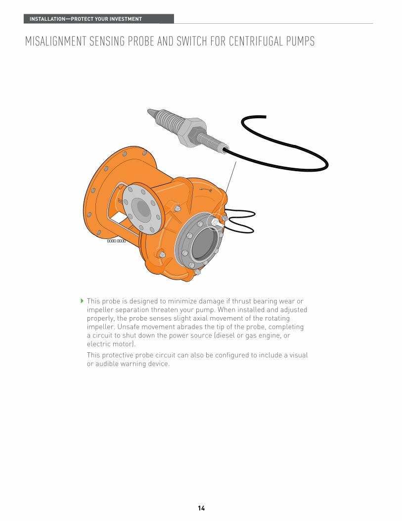
This probe is designed to minimize damage if thrust bearing wear or impeller separation threaten your pump. When installed and adjusted properly, the probe senses slight axial movement of the rotating impeller. Unsafe movement abrades the tip of the probe, completing a circuit to shut down the power source (diesel or gas engine, or electric motor).
This protective probe circuit can also be configured to include a visual or audible warning device.
mIsalIgnmenT sensIng Probe and swITcH for cenTrIfugal PumPs
inStaLLation—PRotEct YoUR invEStMEnt

15
Pump Priming 16,17 determine Pump rotation 18 start-up check list 19
conTenTs
SEction 2—StaRt-UP

16
Primer IsolationValve
Berkeley DischargePriming Valve orButterfly Valve.
787 0394
Han-DeePrimer
Suction toWater Source
For Engine Exhaust Type PrimerLocate connection at leastone pipe diameter from pump case.
sucTIon lIfT wITH PrImIng PumP Close air tight valve on discharge. Han-Dee Primer operation:1. Open Han-Dee Primer isolation valve.2. Work handle of Han-Dee primer up and down
to evacuate air from the suction line. (Refer to primer owner’s manual for proper procedure).
3. When water flows freely from primer, close Han-Dee Primer isolation valve. (Pump case should now be filled with water).
Immediately start pump. Slowly open butterfly valve (if used) until desired flow is achieved. (Discharge Priming Valve will open automatically).
sucTIon lIfT wITH engIne exHausT PrImer
Locate exhaust primer connection as shown above.
For operation, refer to specific instructions included with exhaust primer.
StaRt-UP
PumP PrImIng

17
HYdraulIcallY balanced PumPs Hydraulically balanced pumps operate with a very low positive pressure across the stuffing box, permitting a much looser fit of the packing rings around the shaft sleeve to control the loss of water from the pump through the stuffing box. Because of the looser fit of the packing rings, air can be more easily drawn into the pump through the stuffing box when priming the pump with an air evacuation type primer.
A grease fitting, communicating through the side of the stuffing box to a lantern ring in the packing set, is provided to grease seal the stuffing box to prevent air leakage during priming.
If pump cannot be primed due to air leakage through the stuffing box, do not tighten packing. Instead, pump grease into fitting until back pressure occurs, forcing grease into lantern ring to seal the stuffing box. After priming, when unit is put into operation, the grease will be flushed out through the packing by water flowing outward through the stuffing box. Proceed with normal adjustment of the packing as described in pump owners manual. Note that the grease seal is used only for control of air leakage during priming, and that only the packing gland is used to control the flow of water through the stuffing box during normal operation.
sucTIon lIfT wITH fooT valve Close air tight valve on discharge. Remove pipe plug from highest opening in pump case.
Completely fill pump and suction piping with water.
Rotate shaft slowly to allow any air trapped in impeller to escape.
When all air has been forced out of pump, replace pipe plug. Use pipe joint compound on plug threads and tighten as necessary to prevent leakage.
flooded sucTIon Close air tight valve on discharge. Open air vent (or pipe plug) in the highest tapped opening in pump case.
Open inlet isolation valve, allowing water to fill the pump completely and force all air out through vent.
Rotate shaft slowly to allow any air trapped in impeller to escape.
Close vent opening when water without air emerges.
StaRt-UP
PumP PrImIng
18
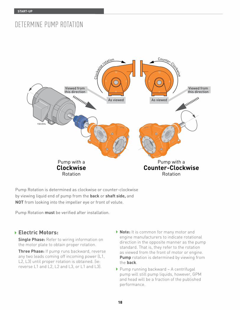
Viewed fromthis direction
Viewed fromthis direction
Pump with aClockwise
Rotation
Pump with aCounter-Clockwise
Rotation
Cloc
kwise
rotation
H 806H 806
H 806H 806
As viewed
938 0594
12
6
39
As viewed
12
6
39
Counter-Clockwise
Electric Motors: Single Phase: Refer to wiring information on
the motor plate to obtain proper rotation. three Phase: If pump runs backward, reverse
any two leads coming off incoming power (L1, L2, L3) until proper rotation is obtained. (ie: reverse L1 and L2, L2 and L3, or L1 and L3).
note: It is common for many motor and engine manufacturers to indicate rotational direction in the opposite manner as the pump standard. That is, they refer to the rotation as viewed from the front of motor or engine. Pump rotation is determined by viewing from the back.
Pump running backward – A centrifugal pump will still pump liquids, however, GPM and head will be a fraction of the published performance.
Pump Rotation is determined as clockwise or counter-clockwise by viewing liquid end of pump from the back or shaft side, and not from looking into the impeller eye or front of volute.
Pump Rotation must be verified after installation.
deTermIne PumP roTaTIon
StaRt-UP
19
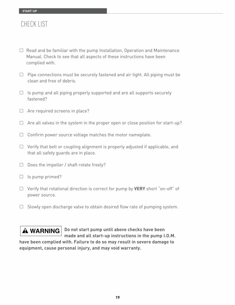
� Read and be familiar with the pump Installation, Operation and Maintenance Manual. Check to see that all aspects of these instructions have been complied with.
� Pipe connections must be securely fastened and air tight. All piping must be clean and free of debris.
� Is pump and all piping properly supported and are all supports securely fastened?
� Are required screens in place?
� Are all valves in the system in the proper open or close position for start-up?
� Confirm power source voltage matches the motor nameplate.
� Verify that belt or coupling alignment is properly adjusted if applicable, and that all safety guards are in place.
� Does the impeller / shaft rotate freely?
� Is pump primed?
� Verify that rotational direction is correct for pump by vERY short “on-off” of power source.
� Slowly open discharge valve to obtain desired flow rate of pumping system.
do not start pump until above checks have been
made and all start-up instructions in the pump i.o.M. have been complied with. failure to do so may result in severe damage to equipment, cause personal injury, and may void warranty.
cHeck lIsT
StaRt-UP
20
maInTenance record
MaintEnancE
21
Impeller replacement 22 Packing replacement 23 mechanical seal replacement – disassembly, motor drive 24 mechanical seal replacement – reassembly, motor drive 25 routine maintenance 26,27 recommended spare Parts 28 winterizing 28
conTenTs
SEction 3—MaintEnancE

22
H 806H 806
1149 0794
Clockwise RotationVolute shown.
Unfasten hardware holding volute to bracket.
Remove volute to expose impeller. Peel off old volute gasket (or O-Ring) and discard.
notE: Certain models such as the B4EY, are constructed with a suction flange which is removed first to access the impeller.
1
1150 0794
REM
OVE
REM
OVE
H 806H 806
H 806H 806
Clockwise rotation as viewedfrom shaft end.
Right Hand Thread
Hold shaftstationarybeing carefulnot to damageshaft.
Hold shaftstationarybeing carefulnot to damageshaft.
Counter-Clockwise rotationas viewed from shaft end.
Left Hand Thread
Hold impeller stationary and remove impeller screw and associated hardware.
Hold shaft stationary and remove impeller by turning in the direction shown for either clockwise or counter-clockwise pump rotation.
notE: Do not use impeller vanes for leverage.
2
1151 0794
Key
If motor drive with keyed shaft, refer to mechanical seal disassembly drawing.
For bearing frame pumps with keyed shaft, consult with factory for approved method of impeller removal.
THreaded sHafT - frame mounT
MaintEnancE—iMPELLER REPLacEMEnt
keYed sHafT

23
1147 0794
Motor / Engine not shownfor clarity.
Typical Packing Arrangement
Metallic Ring
Lantern Ring
Ring Joints
PackingRings
826 0394
Motor / Engine not shownfor clarity. Motor / Engine not shown
for clarity.
PackingGland
PackingHooks1 2
Unfasten hardware holding Packing Gland in place and slide back on shaft to expose packing rings. A split Packing Gland with threaded studs is shown.
Remove packing rings from stuffing box using two commercially available Packing Hooks as shown.
Slide Lantern Ring (if used) back to expose any remaining rings, including metallic. Remove them in the same manner.
Clean shaft sleeve and Packing Gland. Inspect shaft sleeve for wear, replace if needed. Install new packing rings in stuffing box by placing over shaft sleeve and pushing them in as far as they will go.
Rotate ring joint 90 degrees when installing each ring as shown.
Slide packing gland into position, then gently and evenly tighten nuts to force rings into place and seat (do not overtighten). Loosen nuts again to hand tight.
Start primed pump and allow packing to leak liberally.
Evenly tighten gland nuts one complete turn at a time until leakage is reduced to 40 to 60 drops per minute.
Procedure and parts will vary slightly depending on pump style.
removal
MaintEnancE—PacKing Ring REPLacEMEnt
InsTallIng new rIngs
24
Key
ShaftSleeve
1139 0794
Gear PullerFinger
Gear PullerFinger
Gear PullerJackscrew
Note:A hexnut placed between thejackscrew and shaft end willprevent damage to the shaftand impeller screw threads.
1138 0794
1135 0794
1137 0794
1 2
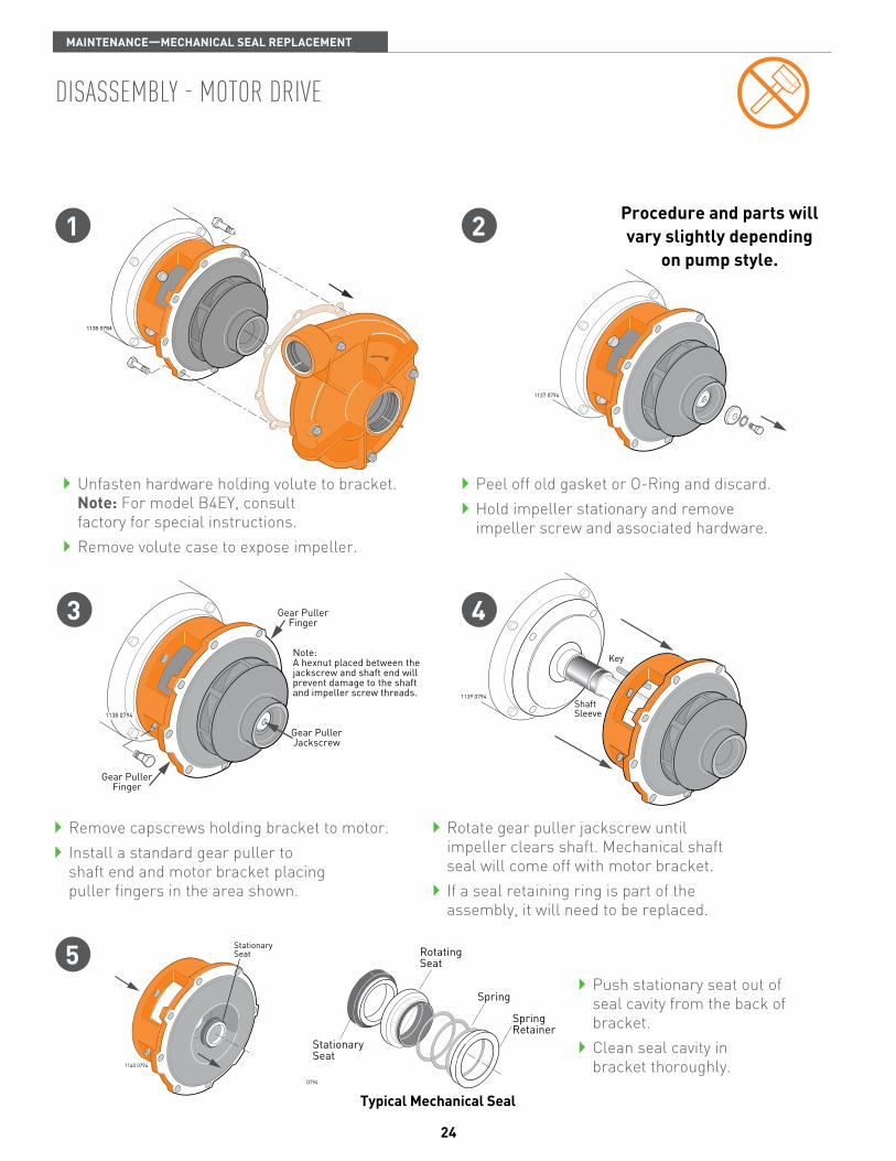
Unfasten hardware holding volute to bracket. note: For model B4EY, consult factory for special instructions.
Remove volute case to expose impeller.
Peel off old gasket or O-Ring and discard. Hold impeller stationary and remove impeller screw and associated hardware.
Procedure and parts will vary slightly depending
on pump style.
Remove capscrews holding bracket to motor. Install a standard gear puller to shaft end and motor bracket placing puller fingers in the area shown.
Rotate gear puller jackscrew until impeller clears shaft. Mechanical shaft seal will come off with motor bracket.
If a seal retaining ring is part of the assembly, it will need to be replaced.
StationarySeat
1140 0794
Push stationary seat out of seal cavity from the back of bracket.
Clean seal cavity in bracket thoroughly.
StationarySeat
RotatingSeat
Spring
SpringRetainer
1189 0794
typical Mechanical Seal
5
43
dIsassemblY - moTor drIve
MaintEnancE—MEchanicaL SEaL REPLacEMEnt
25
If shaft is threaded, cover threadswith tape to protect seal duringinstallation.
1143 0794
1146 0794
Truarc
1144 0794�
�
1145 0794
Key
1 2
5
43
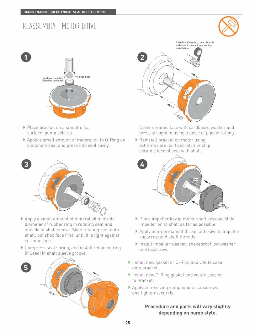
Place bracket on a smooth, flat surface, pump side up.
Apply a small amount of mineral oil to O-Ring on stationary seat and press into seal cavity.
Cover ceramic face with cardboard washer and press straight in using a piece of pipe or tubing.
Reinstall bracket on motor using extreme care not to scratch or chip ceramic face of seal with shaft.
Apply a small amount of mineral oil to inside diameter of rubber ring in rotating seat and outside of shaft sleeve. Slide rotating seat onto shaft, polished face first, until it is tight against ceramic face.
Compress seal spring, and install retaining ring (if used) in shaft sleeve groove.
Place impeller key in motor shaft keyway. Slide impeller on to shaft as far as possible.
Apply non-permanent thread adhesive to impeller capscrew and shaft threads.
Install impeller washer, shakeproof lockwasher, and capscrew.
Procedure and parts will vary slightly depending on pump style.
Polished FaceCardboard washer(Supplied with seal)
1142 0794
Install new gasket or O-Ring and volute case onto bracket.
Install new O-Ring gasket and volute case on to bracket.
Apply anti-seizing compound to capscrews and tighten securely.
reassemblY - moTor drIve
MaintEnancE—MEchanicaL SEaL REPLacEMEnt

26
A well maintained pumping system will extend the life of the unit and require fewer repairs. This means less down-time which can be very critical when a constant delivery of liquid is required.
A routine maintenance and inspection schedule should be set up on a weekly, quarterly, and annual basis with records kept of these actions. (Refer to individual pump owner’s manual for required maintenance and/or lubrication).
wEEKLY
observe the following to verify that pump unit is operating properly.
vibration – All rotating machines can be expected to produce some vibration. However, excessive vibration can reduce the life of the unit. If the vibration seems excessive, discontinue operation, determine cause, and correct.
noise – When the unit is operating under load, listen closely for unusual sounds that might indicate that unit is in distress. Determine the cause and correct.
operating temperature – During operation, heat is dissipated from the pump bearings and the driver. After a short period of time, the surface of the pump bracket will be quite warm (as high as 150°F), which is normal. If the surface temperature of the pump bracket or driver is excessive, discontinue operation, determine cause of the temperature rise, and correct. Bearings will run hotter for a brief run-in period after packing which is normal. However, worn bearings will cause excessive temperatures and need to be replaced. The pump unit is cooled by the water flowing through it, and will normally be at the temperature of the pumping liquid.
Stuffing Box – After a short period of operation, verify that the stuffing box area and gland are not hot. If heating is detected, loosen the gland nuts evenly until water is just running out of stuffing box in a DROPLET form. Water must not be streaming or spraying out. Verify cool operation periodically. Adjust gland nuts EVENLY as necessary for lubrication and cooling of the packing. If packing has been tightened to the limit of the packing gland travel, additional packing is necessary.
Mechanical Seal – Inspect seal for leakage. There should be no leakage at mechanical seal.
Inspect suction line and/or screen for flow obstruction.
rouTIne maInTenance
MaintEnancE
27
qUaRtERLY
Pump and Piping connections – Inspect all system piping connections for leakage or possible misalignment. Misalignment of pipe connections to the pump will put excessive strain on the pump case and can cause damage to internal components of both the pump and motor. If stress on the pump case is suspected, adjust pipe supports to correct. For flange connections, misalignment can be checked by shutting down the pump, and removing the pipe flange bolts on the pump connections. If the mating flanges come apart or shift, there is pressure at the connection(s) and adjustments should be made to the piping supports until flanges mate without force. This procedure can be done throughout piping system.
Check pump foundation for soundness and see that all hold-down bolts are secure.
Complete any lubrication requirements as dictated by pump/driver owners manuals.
Inspect packing or mechanical seal for possible replacement. Examine shaft sleeve, if present, for wear and replace it if necessary.
Inspect pumping plant panel for signs of wear (ie: replace pitted contactors, etc., as needed).
Check pump and/or motor bearings for signs of wear. Repack or replace as required.
annUaLLY
Inspect pump and entire pumping system for signs of wear.
Inspect system valves, screens, etc.
Check electric motor windings for degradation, rewind if necessary.
Check pump impeller eye clearance.
Inspect impeller, volute case, and seal chamber for signs of excessive wear or corrosion.
rouTIne maInTenance
MaintEnancE
28
recommended sPare ParTs
The number and type of spare parts kept on hand at any pump site is dictated by the severity of the service in which the pump is used. That is, a pump servicing a golf course’s sprinkling system should not be down because of a simple case gasket, or a subdivision out of water because of a failed mechanical seal.It is recommended that the following spare parts be kept on-site as a minimum back-up to service pump and reduce down-time. Parts shown do not apply to all models. Check your model/style against parts breakdown drawing(s) when selecting spares.
► mechanical shaft seal
► Packing set and packing hooks
► shaft sleeve(s)
► Impeller wear ring
► all gaskets and o-rings required for one pump
► retaining rings
If having a pump non-operational has severe consequences, a back-up pump should be considered. Otherwise, a back-up impeller, volute case, bearings and shaft, would be prudent.
wInTerIzIngIf pump is to be out of service for an extended period of time, such as the winter months, the following storage procedures should be followed.
► remove exterior dirt and grime or any substance that may trap moisture. exposed metal is subject to oxidation, prime and repaint if necessary.
► flush suction and discharge lines. check for leaks at this time and replace any worn gaskets.
► remove lowest plug in pump and drain pump casing and suction and discharge lines.
► lubricate bearings (refer to owners manual).
► If possible, keep unit clean and dry during storage period to guard against corrosion.
► seal all open ports to keep out foreign objects such as insects, rodents, dust and dirt.
► rotate driver shaft periodically to prevent freeze-up of internal components.
► shelter pump from the elements when possible.
MaintEnancE _ SPaRES/wintERizing
29
nameplate data 30 Part nomenclature – electric motor drive 31 Part nomenclature – bearing frame mount 32 Part nomenclature – s.a.e. engine mount 33 Part nomenclature – air cooled engine drive 34 Part nomenclature – air cooled engine drive, self Prime 35
conTenTs
SEction 4—PUMP noMEncLatURE

30
MODEL S.N. OR DATE
IMPELLER DIA.
BERKELEY®
B.M.
788 0394
B54598
G100894B3TPMS
6-1/8"
model number Example: B3tPMS
► B – Berkeley Type B Centrifugal
► 3 – Pump discharge size - 3 inch
► t – Nominal Impeller diameter - 6 inch
► P – Pump Type - Electric Motor Drive
► M – Impeller capacity - Medium
► S – Mechanical Seal
(refer to berkeley catalog for model nomenclature information)serIal number
Example: g100894 ► Date code. Represents the day, month and year that the pump was built.
ImPeller TrIm Example: 6-1/8”
► Size of outside diameter of Impeller. Required when ordering replacement impeller.
bIll of maTerIal numberExample: B54598
► Also referred to as catalog number. Use this number when ordering repair parts or service requirements. This is the most important number on the tag for pump identification purposes.
PUMP noMEncLatURE - naMEPLatE data

31
Volute Case
BalanceRing
Balance RingGasket
ImpellerCapscrew
ShakeproofLockwasher
ImpellerWasher
Impeller
MotorBracket
ShaftSleeve
LanternRing
MetallicRing
PackingGrease Cup
or fitting
PackingGland
PackingRings Gasket
or O-Ring
786 0394
VoluteCase
ImpellerCapscrew
ShakeproofLockwasher
Wear Ring
ImpellerWasher
Impeller
Seal RetainingRing
ShaftSleeve
MotorBracket
Gasketor O-Ring
MechanicalSeal
771 0294Truarc
► Electric Motor not shown.
► Drawing is representative of a typical motor drive pump. Parts on some models will vary slightly.
► Electric Motor not shown.
► Drawing is representative of a typical motor drive pump. Parts on some models will vary slightly.
mecHanIcal seal
PUMP noMEncLatURE - ELEctRic MotoR dRivE
PackIng
32
H 806H 806
Truarc
BalanceRing
BalanceRing
Gasket
PackingGland
PumpShaft
VoluteCase
VoluteGasket
WearRing
ImpellerCapscrew
Seal Retainer
O-Ringor Gasket
MechanicalSeal
ShakeproofLockwasherBracket
(Bearing Frame)
Impeller
Slinger
InnerBearingCap
OuterBearingCap
ImpellerWasher
PumpShaft
Single rowBearing
Double rowBearing
RetainingRing
ThrustRing
772 0394
ShaftSleeve
LanternRing
MetallicRing
PackingRingsPacking
Grease Cupor Fitting
mecHanIcal seal
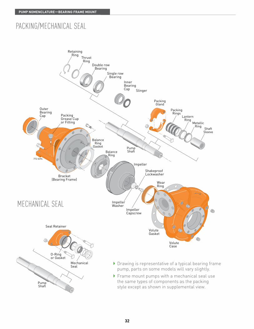
Drawing is representative of a typical bearing frame pump, parts on some models will vary slightly.
Frame mount pumps with a mechanical seal use the same types of components as the packing style except as shown in supplemental view.
PackIng/mecHanIcal seal
PUMP noMEncLatURE—BEaRing fRaME MoUnt

33
ShaftSleeve
BalanceRing
BalanceRing
Gasket
PackingGrease
Cup
LanternRing
MetallicRing
PackingGland
PackingRings
VoluteCase
Volute Gasketor O-Ring
WearRing
ImpellerCapscrew
ShakeproofLockwasherBracket
773 0394
SAE 1: 12 Holes on 20.88" Bolt CircleSAE 2: 12 Holes on 18.38" Bolt CircleSAE 3: 12 Holes on 16.88" Bolt CircleSAE 4: 12 Holes on 15.00" Bolt CircleSAE 5: 8 Holes on 13.12" Bolt Circle
Impeller
SlingerOil Seal
ImpellerWasher
BERKELEY
Double RowThrust Bearing
Single RowBearing
Outer BearingCap Shoulder
Ring
PumpShaft
PumpShaft
Seal Retainer
O-Ringor Gasket
MechanicalSeal
L
L
Drawing is representative of a typical SAE engine mounted pump, parts on some models will vary slightly.
SAE engine mounted pumps with a mechanical seal use the same types of components as the packing style except as shown in supplemental view.
mecHanIcal seal
PackIng/mecHanIcal seal
PUMP noMEncLatURE— S.a.E. EnginE MoUnt
34
SlingerO-Ring
ShaftSleeve
MechanicalSeal
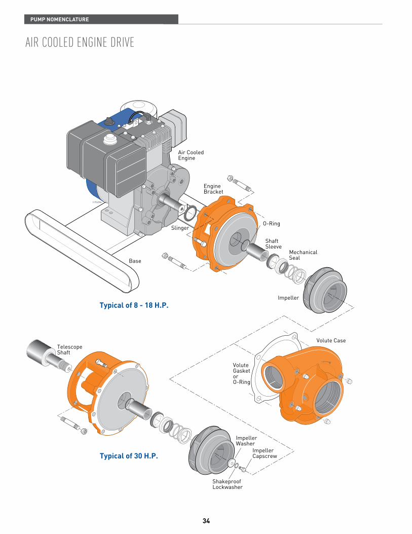
Typical of 30 H.P.
Typical of 8 - 18 H.P.Impeller
Base
ImpellerWasher
ImpellerCapscrew
ShakeproofLockwasher
EngineBracket
Air CooledEngine
Volute Case
VoluteGasketorO-Ring
TelescopeShaft
R J 1 9L M ON OFF
1175 0794
aIr cooled engIne drIve
PUMP noMEncLatURE

35
Pumps with 4" discharge
CompanionFlange
FlangeGasket
Oil Seal
Slinger
EngineBracket
Case Gasket
ShaftSleeve
MechanicalSeal
ImpellerWasher
ShakeproofLockwasher
ImpellerCapscrew
Semi-openImpeller
Telescope Shaft(30 H.P.)
Base
Volute(Pump Case)
ClackWeight
ClackWasher
RubberClack
SuctionCover
774 0294
SleeveO-Ring
777 0294
Handle
Seal Plate
O-Ring
MechanicalSeal
Impeller
NeckRing
WearWasher
Diffuser
ClackAssembly
PumpCase
DischargeCap 1-1/2"
DischargeCap 1"
DischargeCap 2"
Gas Engine not shown.
Base shown is representative of small H.P. models.
Gas Engine not shown.
casT Iron
alumInum
aiR cooLEd EnginE dRivE-SELf PRiME

USA CANADA293 WRIGHT STREET, DELAVAN, WI 53115 WWW.BERKELEYPUMPS.COM 269 TRILLIUM DRIVE, KITCHENER, ONTARIO, CANADA N2G 4W5PH: 888-237-5353 ORDERS FAX: 800-321-8793 PH: 888-363-7867 ORDERS FAX: 519-748-2553
Because we are continuously improving our products and services, Pentair reserves the right to change specifications without prior notice.
© 2012 Pentair Ltd. All Rights Reserved. b1521 (12/3/12)


