
1
Managing the Health and Safety of Li-Ion Batteries using a Battery Electronics Unit (BEU) for Space Missions
George AltemoseAeroflex Plainview, Inc.www.aeroflex.com/BEU
NASA Battery Power Workshop 11/27/07 – 11/29/07

2
Introduction
Lithium-Ion batteries have become prominent in space applications, because of their lighter weight and lower cost than NiH2 batteriesLithium-Ion batteries require electronic cell balancing to reduce the possibility of overcharging or deep dischargingCell balancing is required to achieve the maximum possible mission life for a Lithium-Ion battery

3
BEU Development History
The Aeroflex 8627 Battery Electronics Unit (BEU) was designed, fabricated and tested to meet Boeing specifications for use with Lithium-Ion batteries on the Boeing 702B and other satellitesThe basic approach for the BEU was developed by Boeing, and is described in Patent 6,873,134. This patent describes transformer-coupled DC-DC converters that transfer charge over a bidirectional Share BusAeroflex has completed the electrical and mechanical design of the BEU. Engineering Models (EM) and Engineering Qualification Models (EQM) have been fabricated and testedIn addition to cell balancing, the BEU provides additional functions:– Cell voltage monitoring– Battery voltage monitoring– Telemetry (MIL-STD-1553)– Bypass relay driver circuits– Reconditioning load control
4
Benefits of Cell Balancing
Cell balancing equalizes the charge among the cells in a batteryUnlike other types of cells, Lithium-Ion cells do not exhibit natural cell-to-cell balancing mechanisms Lithium-Ion batteries may become unbalanced, leading to one cell becoming overcharged, causing cell damageIf cells are balanced, no cell will reach overcharge if the battery is charged properlyDuring discharge, balanced cells discharge equallyFor satellites with high power or long mission life, balancing provides:– Minimum battery size: no additional capacity is required to allow
for imbalance– Protection from cell damage due to over-charge or over-discharge

5
Desirable Features of a Cell Balancing System
Autonomous operationBalancing of all cells to within millivolts of each otherBalancing current directly proportional to voltage difference between cellsOperate continuously during charge, discharge and standby modesAccurate cell voltage monitoring and telemetryHigh reliabilityFault tolerant, for both cell faults and circuit faultsNegligible degradation due to temperature, life and radiationProtection from Single Event Upset (SEU) faultsLow powerLight weight
6
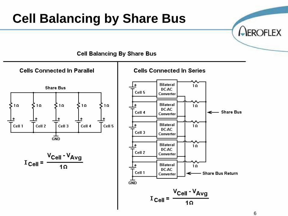
Cell Balancing by Share Bus

7
Cell Balancing Characteristic Curve
8
Functional Description of Balancing Circuit
Active DC-DC Converters interconnect all cells, through a Share BusControlled impedance in each balancing circuit sets the Transfer Ratio to 1 ohmEach balancing circuit contains a 1 amp fuse, which opens if a cell shortsBalancing is continuous and autonomousCurrent flows from the higher voltage cells into the Share BusCurrent flows into the lower voltage cells from the Share BusBalancing does not utilize voltage measurements or computations

9
Cell Balancing Circuits

10
Cell Balancing Circuit Waveforms
11
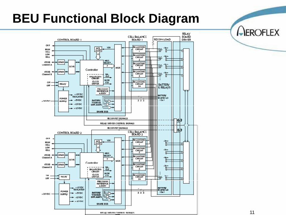
BEU Functional Block Diagram

12
BEU Functional Block Diagram(Primary Side Only)
13
Circuit Description – Balancing Circuit
Forward converter with resonant resetResonant frequency is determined by parallel combination of transformer primary inductances and circuit capacitancesTransformer secondaries are connected to the Share Bus by 1 ohm resistors and 1 amp fusesBalance Clock is generated by Phase Lock Loop (PLL), and provides zero-loss switchingPLL also generates a Monitor Clock synchronous to the Balance Clock1 amp fuses are designed to open in case of a shorted cell and allows proper balancing among the remaining cells

14
Circuit Description –Monitoring and High/Low Limits
Monitor Clock drives Sample-and-Hold (S/H) circuits to derive monitor voltages equal to the cell voltagesMonitor voltages are connected through Multiplexer (MUX) to the 12-bit A/D Converter controlled by the ASIC processor.MUX inputs also include three battery voltage buffers and a precision 4.000 volt referenceASIC processor performs auto-calibration (slope and offset correction) using the precision 4.000 volt referenceASIC processor checks each cell voltage against preset limits, which are stored in the PROM. Typical limits are as follows:– Low Cell: 3.2 volts– High Cell: 4.2 volts– Overvoltage Protection: 4.4 volts

15
Circuit Description: Custom ASIC
Fully synchronous designPLL and PWM (for power supply clock) circuits run at 24 MHzAll other logic runs at 12 MHzState machine architecture with no undefined statesGuaranteed recovery from single event upsetsRHA Designator R: 100 Krad (Si)Process: Aeroflex UT 0.6 µ CRH Commercial RadHard Gate Array

16
Circuit Description –SµMMIT 1553 Bus Controller
Proven technology: has been used on many previous programs
Rad hard to 100 Krad (Si)

17
Circuit Description – Bypass Relay Drivers
Provides 2 amp pulses, compatible with NEA Battery Cell Isolation Switches (referred to as “relays”)Requires three separate and independent 1553 commands to activate a bypass relay.Two-fault tolerant with respect to accidental contact closureOR’ed inputs can operate from two redundant Control Cards
18
Circuit Description –Reconditioning Load Control
Switches 5 amp battery reconditioning load (load resistor is located with battery)Immune to single-point failures (2 series FET switches with transformer-coupled drive circuits)Requires two separate and independent 1553 commands to turn on the reconditioning loadOR’ed inputs can operate from two redundant Control Cards
19
Circuit Description –Internal DC-DC Voltage Converter
Input Voltage Range of 20-36 VDCProvides output voltages of +5 VDC (+ 1%) and + 12 VDCFlyback topology with linear post-regulators on every outputImmune to spurious SEU outputs to protect ASIC and SµMMIT from SEU transientsFully compliant with MIL-STD-461C EMC requirements

20
Redundancy & Other Reliability Enhancements
Redundant balancing circuits (Balancing Card and Control Card) may be used simultaneously or individuallyBypass Relay Driver circuits are two-fault tolerant, with respect to unwanted turn-on of bypass relayReconditioning Load control circuit is one-fault tolerant, with respect to unwanted turn-on of the reconditioning loadTriple battery voltage monitoring circuits are provided on each Control Card – Measured battery voltages may be compared to verify
accuracy of measurement circuits
21
Test Results
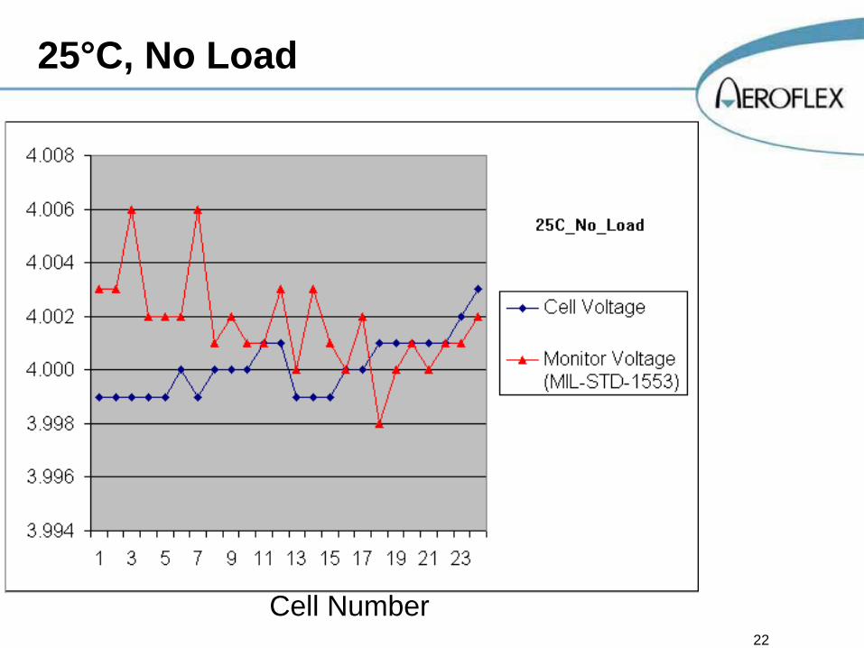
Cell balancing tests were performed using capacitors in place of battery cellsMonitor voltages were sent by telemetry over the 1553 busThe 1 ampere load was provided on one cell by placing a 3 ohm resistor across the cell
22
25°C, No Load
Cell Number

23
+25°C, 1 Amp Load
Cell Number

24
+75°C, No Load
Cell Number

25
+75°C, 1 Amp Load
Cell Number
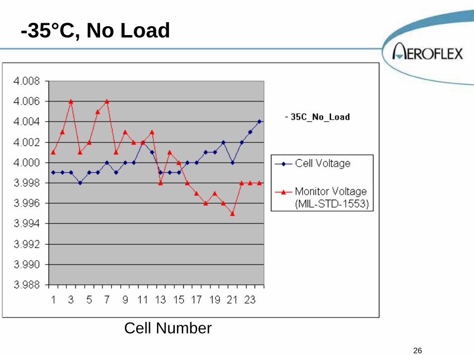
26
-35°C, No Load
Cell Number

27
-35°C, 1 Amp Load
Cell Number
28
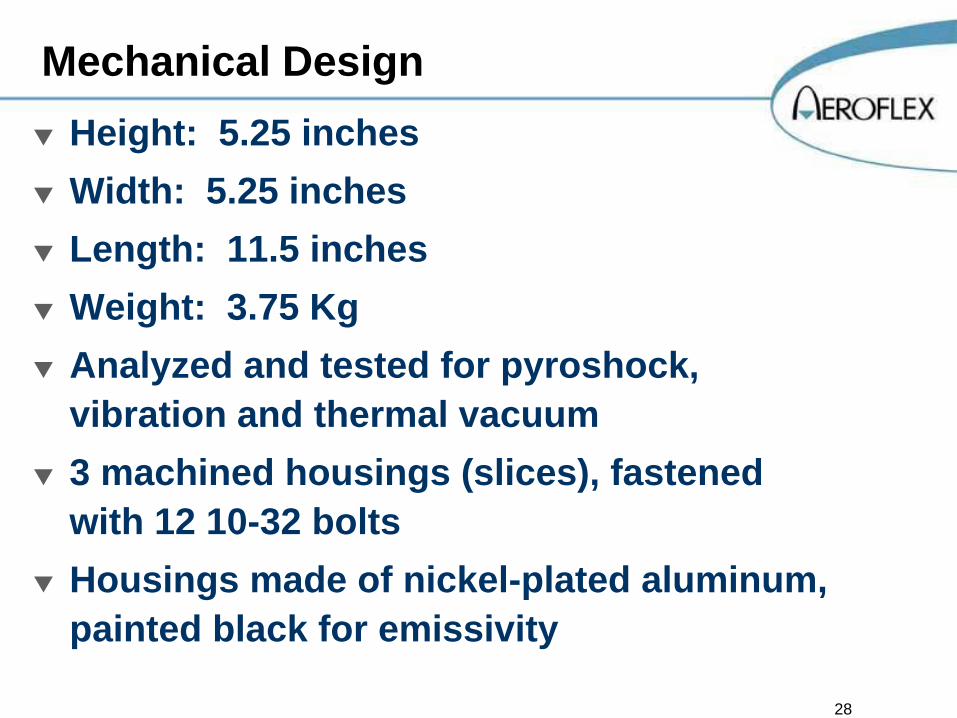
Mechanical DesignHeight: 5.25 inchesWidth: 5.25 inchesLength: 11.5 inchesWeight: 3.75 KgAnalyzed and tested for pyroshock, vibration and thermal vacuum3 machined housings (slices), fastened with 12 10-32 boltsHousings made of nickel-plated aluminum, painted black for emissivity
29
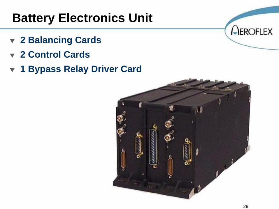
Battery Electronics Unit2 Balancing Cards2 Control Cards1 Bypass Relay Driver Card

30
Balancing Card
24 Cell Balancing Circuits

31
Control CardASIC, with PROM and PORSµMMIT 1553 InterfaceA/D, 4.000V Reference, MUX, 3 Battery Voltage BuffersPower SupplyOn/Off Controls

32
By Pass Relay Driver Card
24 Relay Driver CircuitsReconditioning Load Control Circuit
33
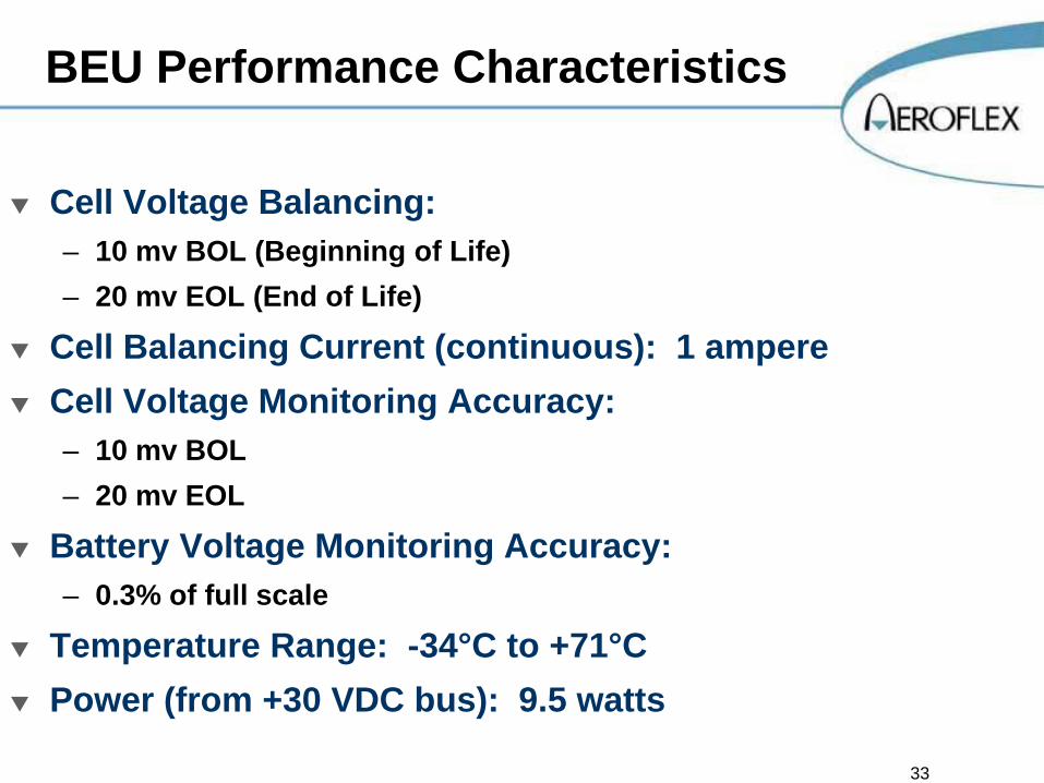
BEU Performance Characteristics
Cell Voltage Balancing:– 10 mv BOL (Beginning of Life)– 20 mv EOL (End of Life)
Cell Balancing Current (continuous): 1 ampereCell Voltage Monitoring Accuracy:– 10 mv BOL– 20 mv EOL
Battery Voltage Monitoring Accuracy:– 0.3% of full scale
Temperature Range: -34°C to +71°CPower (from +30 VDC bus): 9.5 watts

34
Currents Drawn by BEU

35
Summary
Cell balancing has been shown to significantly enhance the mission life of Lithium-Ion batteriesThe Aeroflex BEU meets the specified design goals, including autonomous and continuous cell balancing while operating in a space environment

36
Acknowledgement
The conceptual design of the BEU was performed by Boeing Space Systems, and is described in patent US 6,873,134 B2. The inventors are Stanley Canter, Winnie Choy and Robert MartinelliAeroflex designed and developed the original BEU in accordance with Boeing Space Systems specifications
37
Action Space Guy


