
© DICTATOR Technik GmbH • Gutenbergstr. 9 • 86356 Neusäß • GermanyTel. +49(0)821-24673-0 • Fax +49(0)821-24673-90 • E-mail [email protected] • 20180416 Page 02.071.00
Back Check
Technical Data
Back ChecksWith Hydraulic Damping in the Opening Direction
The DICTATOR back checks with hydraulic damping slow down hinged doors opening too fast and limit the opening angle of the door. Thus they prevent damage to the door and the hinges.
The door can effortlessly be moved by hand. The cushioning of the back check prevents too high opening speed of the door (e.g. by a sudden gust of wind).
The DICTATOR back checks are often used on doors which could bump into a wall or something similar by gusts of wind, draught or just during opening being torn from the user's hand. Beside the damage this could cause to the door, the fittings and possibly the wall, doors opening at uncontrolled speed present a risk of accident not to be underestimated.
The back checks are produced in two basic versions: with or without adjustment of the damping force. Of both versions there are available several series for different sizes of doors. Our technical service would be happy to determine free of charge the back check for your application.
Cylinder diameter TB: 23, 28 mm; TBR: 28, 35 mmPiston rod diameter TB: 10, 14 mm; TBR: 10, 14 mmCylinder steel zinc-plated or coated in RAL colours, AISI 304, AISI 316 Piston rod hard-chrome plated, AISI 304, AISI 316Door size* up to width 1.30 m, height 2.50 m (with 3 hinges)Door weight* up to ca. 200 kg; *for larger doors on demandMaximum opening angle 120° Mechanical stop (ca.) TB: 1023: 250 N, 1428: 350 N, 1435: 500 N

© DICTATOR Technik GmbH • Gutenbergstr. 9 • 86356 Neusäß • GermanyTel. +49(0)821-24673-0 • Fax +49(0)821-24673-90 • E-mail [email protected] • 20180416 Page 02.072.00
Back Check
Operation, Installation and Adjustment
DICTATOR back checks are the ideal solution for exterior doors being exposed to wind or interior doors in surroundings with heavy draught that might slam open. The cushioning by the back check reduces strain both on door (e.g. glass panes) and door hinges. One side of the back check is fixed to the upper door frame, the other side to the door leaf. When the door is opened normally, there is almost no cushioning effect of the back check perceptible. As soon as the door is opened very fast either by hand or e.g. a gust of wind, the back check hydraulically slows down this sudden movement.
When using a non-adjustable back check TB model the cushioning range can be reduced on site by withdrawing some of the oil through the valve screw. If this necessary, please contact our technical customer service.
The damping force of the adjustable back checks TBR can be adjusted continuously and at any time. The piston rod of the models without mechanical stop has to be pulled out as far as possible and then - while still being pulled - be turned. With the types with mechanical stop it works the other way round: push the piston rod as far as possible into the cylinder and then turn it carefully.
When installing the back check, please make sure it is fixed securely to the door and the frame. If door or frame are made from thin steel sheet or something similar, we recommend to use mounting plates. Furthermore, the piston rod should not be fully compressed when the door is closed. There should be left approx. 10 mm of stroke in order to ensure the door can be opened without problems.
Damping Adjustment
Installation
Accessories
Mechanical Stop
The back checks are available with complete installation kits for the different types of doors, all packed in a unit box. This should facilitate the choosing. Infor-mation about the different sets is to be found beginning on page 02.075.00, the exact dimensions of the fixing accessories are shown beginning on page 02.077.00.
Apart from the sets the fixing accessories are also separately availabe. For the 1435 series no sets are available as here the installation situations vary a lot. The necessary installation accessories have to be ordered additionally to the back check.
The back checks can be furnished with an integrated mechanical stop for the door in the open position (stop at about 3° before the piston rod is completely extended).
Choosing the Correct Back Check
The tables with the different standard models show the weight of interior doors up to which the respective back check may be used. When installing a back check without adjustment on a frequently used door, you should always choose the series 1428 with 250 mm stroke (also with the sets)! When you intend to install back checks on exterior doors or on doors with high pressure differences or heavy draught, please contact our advisory service. For this application we need the following data: - Opening angle, weight, dimensions, thickness and material of the door - Width and material of the door frame - Mechanic stop required: yes/no- Installation on the side of the hinges or on the side opposite to the hinges- An overhead door closer is mounted on the door: yes/no- If yes: On which side of the door?- On the door leaf is mounted the guide rail/the overhead door closer.- Drawings or pictures, if possible.

© DICTATOR Technik GmbH • Gutenbergstr. 9 • 86356 Neusäß • GermanyTel. +49(0)821-24673-0 • Fax +49(0)821-24673-90 • E-mail [email protected] • 20180416 Page 02.073.00
Back Check
ø Z
ø K
Total length La
Stroke
Dimensions
Non-Adjustable Back Checks TB
The economic and non-adjustable types TB are mainly intended for industrial applications (e.g. for hall doors opening to the outside). There are produced two series of back checks TB with the diameters 1023 and 1428. The standard types are shown below. Of course, there are available differing lengths. In addition the back checks TB can also be provided with an integrated mechanical stop. By default the steel version is zinc-plated. On demand coating in RAL colours is also possible. The dimensions of the fixing eyelet are to be found on the next page.
Technical Data and Order Information
* The back checks with the part numbers 302008 and 302009 are longer than the standard models. They are specifically inten-ded for the installation together with a guide rail door closer.
The following list shows only a choice of the available models. We gladly will provide detailed advice on the appropriate model and of course will manufacture it, also single units and models which are not listed below. Some of the back checks TB are also available as a set with the appropriate fixing accessories. Information about the different sets you will find on page 02.071.00.
Ø K[mm]
Ø Z[mm]
Stroke[mm]
LengthLa
[mm]
Doorweightup to
Max. door
opening
Me-chanic.
stop
Part no.
Steel zinc-plated AISI 304 AISI 316
10 23 200 500 50 kg 95° no 302000 302002 302004
10 23 200 500 50 kg 95° yes 302001 -
10 23 200 510 50 kg 95° yes - 302003 302005
10 23 250 600 50 kg 120° no 302006 302010 302012
10 23 250 600 50 kg 120° yes 302007 - -
10 23 250 610 50 kg 120° yes - 302011 302013
10 23 250 660 50 kg 120° no 302008* - -
10 23 250 660 50 kg 120° yes 302009*
14 28 200 500 90 kg 95° no 302014 - -
14 28 200 510 90 kg 95° no - 302016 302018
14 28 200 510 90 kg 95° yes 302015 302017 302019
14 28 250 600 200 kg 120° no 302020 302022 302024
14 28 250 610 200 kg 120° yes 302021 302023 302025
14 28 300 750 200 kg 120° no 302026 302028 302030
14 28 300 750 200 kg 120° yes 302027 302029 302031
14 28 400 1000 200 kg 120° no 302033 302035 302037
14 28 400 1000 200 kg 120° ja 302034 302036 302038
© DICTATOR Technik GmbH • Gutenbergstr. 9 • 86356 Neusäß • GermanyTel. +49(0)821-24673-0 • Fax +49(0)821-24673-90 • E-mail [email protected] • 20180416 Page 02.074.00
Back Check
H
BA
C
D
F
E A
G dick
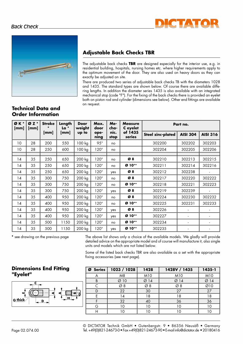
The adjustable back checks TBR are designed especially for the interior use, e.g. in residential building, hospitals, nursing homes etc. where higher requirements apply to the optimum movement of the door. They are also used on heavy doors as they can exactly be adjusted on site. There are produced two series of adjustable back checks TB with the diameters 1028 and 1435. The standard types are shown below. Of course there are available diffe-ring lengths. In addition the diameter series 1435 is also available with an integrated mechanical stop (code "F"). For the fixing of the back checks there is provided an eyelet both on piston rod and cylinder (dimensions see below). Other end fittings are available on request.
Adjustable Back Checks TBR
Technical Data and Order Information
Dimensions End Fitting "Eyelet"
thick
Ø Series 1023 / 1028 1428 1428V / 1435 1435-1
A M8 M10 M10 M10B Ø 10 Ø 14 Ø 14 Ø 14C Ø 8 Ø 8 Ø 8 Ø10D 22 30 27 27E 14 18 18 18F 32 40 36 36G 10 10 10 10H 10 10 10 10
Ø K *[mm]
Ø Z *[mm]
Stroke *
[mm]
Length La *[mm]
Door weight up to
Max. door ope-ning
Me-cha-nic. stop
Measure C eyelet of 1435 series
Part no.
Steel zinc-plated AISI 304 AISI 316
10 28 200 550 100 kg 95° no 302200 302202 302203
10 28 250 600 100 kg 120° no 302204 302205 302206
14 35 250 650 200 kg 120° no Ø 8 302210 302213 302215
14 35 250 650 200 kg 120° no Ø 10** 302211 302214 302216
14 35 250 650 200 kg 120° yes Ø 8 302212 302238 -
14 35 300 750 200 kg 120° no Ø 8 302217 302220 302222
14 35 300 750 200 kg 120° no Ø 10** 302218 302221 302223
14 35 300 750 200 kg 120° yes Ø 8 302219 302239 -
14 35 400 950 200 kg 120° no Ø 8 302224 302230 302232
14 35 400 950 200 kg 120° no Ø 10** 302225 302231 302233
14 35 400 950 200 kg 120° yes Ø 8 302226 - -
14 35 400 950 200 kg 120° yes Ø 10** 302227 - -
14 35 500 1150 200 kg 120° no Ø 10** 302234 - -
14 35 500 1150 200 kg 120° yes Ø 10** 302235 - -
* see drawing on the previous page The above list shows only a choice of the available models. We gladly will provide detailed advice on the appropriate model and of course will manufacture it, also single units and models which are not listed below.
Some of the listed back checks TBR are also available as a set with the appropriate fixing accessories (see next page).

© DICTATOR Technik GmbH • Gutenbergstr. 9 • 86356 Neusäß • GermanyTel. +49(0)821-24673-0 • Fax +49(0)821-24673-90 • E-mail [email protected] • 20180416 Page 02.075.00
Back Check
Order InformationSets
Back Check Sets
The most common TB and TBR back checks are also available as sets complete with the appropriate mounting accessories. The required installation kit depends on the mounting situation, the type of door and frame. On the following page you will find the different kinds of installation and the corresponding accessories kit. Of course the fitting brackets are also available as single parts. Details and the dimensions of all components are shown on page 02.077.00.
Back check sets not adjustable TB (zinc-plated steel)
Part no.
without stop with stopØ K Ø Z Stroke Length La Accessories10 23 250 600 Set 1 300981 30099110 23 250 600 Set 2 300982 30099210 23 250 600 Set 3 300983 30099314 28 250 600 Set 1 30098414 28 250 610 Set 1 30099414 28 250 600 Set 2 30098514 28 250 610 Set 2 300995
14 28 250 600 Set 3 300986 14 28 250 610 Set 3 300996
Back check sets not adjustable TB (AISI 304)
Part no.
without stop with stopØ K Ø Z Stroke Length La Accessories14 28 250 600 Set 1 300987 14 28 250 610 Set 1 30099814 28 250 600 Set 2 30099014 28 250 610 Set 2 30099714 28 250 600 Set 3 30190114 28 250 610 Set 3 301902
Back check sets adjustable TBR (zinc-plated steel)
Part no.
without stop with stopØ K Ø Z Stroke Length La Accessories10 28 250 600 Set 1 300975 10 28 250 600 Set 2 30097610 28 250 600 Set 3 300977
Back check sets adjustable TBR (AISI 304)
Part no.
without stop with stop
Ø K Ø Z Stroke Length La Accessories10 28 250 600 Set 1 300999 10 28 250 600 Set 2 30098010 28 250 600 Set 3 301903

© DICTATOR Technik GmbH • Gutenbergstr. 9 • 86356 Neusäß • GermanyTel. +49(0)821-24673-0 • Fax +49(0)821-24673-90 • E-mail [email protected] • 20180416 Page 02.076.00
Back Check
205262
205197
205261
205197205197
205197
205263
205263
205262
205197205262
205197
205262
205197
205262
205261
205197205197
205197
205263
205263
205262
205197
Installation Kit 1for overlapping and flush doors:Installation kit 1 (part no. 205197 and 205262) for back checks of the 1023, 1028 and 1428 series
Installation Kit 2for backside installation under a large frame:Installation kit 2 (part no. 205197 and 205261) for back checks of the 1023, 1028 and 1428 series
Installation Kits - Mounting Situations
Installation Kit 3for installation under a narrow frame or on the front side of doors overlapping only slightly:Installation kit 3 (part no. 205197 and 205263) for back checks of the 1023, 1028 and 1428 series
Frame
Door type 1a
Door type 1b
Frame
Door type 2
Door type 3a
Door type3b
Frame
Frame
Door type 1c
Door type 1d
Kit 2 is used only on the back side of the door. There has to be enough
space available on the frame for moun-ting flange no. 205261, to achieve a
secure fixing.
Kit 1 can be used for the back (door type 1a with mid-size frame) or front side of an overlapping door
(door type 1b).
Kit 1 also can be used on the back (door type 1c with narrow frame)
or front of a flush door (door type 1d).
Kit 3 with the special bracket no. 205263 allows an installation on the back side of a narrow frame (3a) or on the front of doors with thin
overlapping (3b).

© DICTATOR Technik GmbH • Gutenbergstr. 9 • 86356 Neusäß • GermanyTel. +49(0)821-24673-0 • Fax +49(0)821-24673-90 • E-mail [email protected] • 20180416 Page 02.077.00
Back Check3
2,5
51
1
ø8
ø42
28
3 x ø 5,4 x 120
43
ø8
62
10
27
29
36
17
43
ø8
62
10
27
29
36
17
2 x ø 7
40245
2040
ø 8
4x5,
5
178
4066
10
20
4 20 40
15
16,5
2x ø5,4
ø15
ø8
5025
1
1
2
2
3
3
4
4
A A
B B
C C
D D
E E
F F
Durchschraubplatte incl. Gewindehülse M5, 80x30mm, V2a
B00-000001
Gezeichnet
Kontrolliert
Freig.Fert.
Datum Name
Material:
Gewicht:Oberflächen Kanten
ISO 13715
DICTATOR TECHNIKBerlin
K. u. J. Stech GmbH
Maßstab:
Oberfläche:Bezeichnung:
Artikelnummer:
Zeichnungs-Nr.: B100178.R00
-Alle Kanten entgratet!
Änderungen:
Weitergabe sowie Vervielfälltigung dieser Unterlage, Verwertung umd Mitteilung ihres Inhalts sind nicht gestattet. Zuwiderhandlung verplichtetet zu Schadensersatz. Alle Rechte vorbehalten.
1A4
10.05.2012 ma
1:1InBearbeitung
Gewindehüelse M5 sollte durch M6
Erstproduktion
ersetzt werden
8043
303 14
M5
V2a
7
1
1
2
2
3
3
4
4
A A
B B
C C
D D
E E
F F
1 A4205479
Kontrolliert
Freigabe
Datum Name
26.10.2015 maDICTATOR Technik GmbH
Maßstab: 1:1Bezeichnung:
Artikelnummer:
Zeichnungs-Nr.: 205479_KUNDE.00
Achtung, diese Zeichnnung stellt den Zustand des Artikel zum Zeitpunkt des Drucks dar! Änderungen und Irrtümer sind verbehalten! Sie werden keine Nachricht bei Änderung erhalten!
Gezeichnet
Unterlegplatte mit zwei Gewindebohrung M5 zur Befestigung des Flügelböckchens an Glastüren V2A, inkl. 2x Senkkopfschraube M5x6
9 17,5 25
43
80
5
Unterlegblech mit 2x Schraube
Montageansicht mit verschraubtem Flügelböckchen (nicht Lieferumfang)
All dimensions in mm
For mounting the back checks, different brackets are available. All three standard installation kits (see previous page) include the mounting bracket shown below on the top left (no. 205197). To facilitate mounting if the door is made of thin walls, we offer a counter plate for this bracket. For a space saving mounting on glass doors with aluminium frames we provide the mounting plate TB. The other component of the installation kits is choosen, depending on the mounting situation, from one of the mounting brackets shown at the bottom of this page.
Fixing Accessories: Kits 1 - 3
Mounting flange TB Ø 42 mm, pin 8 mm part no. 205261 (zinc-plated), 205281 (AISI 304)
Mounting bracket TB 50x40x20 mm, pin 8 mmpart no. 205263 (zinc-plated), 205258 (AISI 304)
Mounting bracketpart no. 205197 (zinc-plated), 205249 (AISI 304), 205455 (AISI 316)
Mounting bracket TB 40x40x40 mm, pin 8 mmpart no. 205262 (zinc-plated), 205282 (AISI 304), 205456 (AISI 316)
Counter plate for mounting bracket 205197 part no. 205468 (AISI 304)
For mounting on thin-walled doors:Mounting bracket with counter plate
Frame
Door
Mounting plate TB with 2 threaded holes M5 for mounting bracket 205197part no. 205479 (AISI 304)
When mounted on glass doors with an aluminium frame

© DICTATOR Technik GmbH • Gutenbergstr. 9 • 86356 Neusäß • GermanyTel. +49(0)821-24673-0 • Fax +49(0)821-24673-90 • E-mail [email protected] • 20180416 Page 02.078.00
Back Check
1
1
2
2
3
3
4
4
5
5
6
6
A A
B B
C C
D D
1 A3205462-W
Kontrolliert
Freigabe
Datum Name
15.09.2016 MADICTATOR Technik GmbH
Maßstab: 1:1Bezeichnung:
Artikelnummer:
Zeichnungs-Nr.: 205462-W_FERTIGUNG.
Achtung, diese Zeichnnung stellt den Zustand des Artikel zum Zeitpunkt des Drucks dar! Änderungen und Irrtümer sind verbehalten! Sie werden keine Nachricht bei Änderung erhalten!
Gezeichnet
Befestigungswinkel TB 180x70x53 mm, für Bolzen 8 oder 10 mm, verzinkt
130180
6
25
70
30
R15
6,64x
38
53
12,5
1
1
2
2
3
3
4
4
A A
B B
C C
D D
E E
F F
1 A4205489
Kontrolliert
Freigabe
Datum Name
09.06.2016 maDICTATOR Technik GmbH
Maßstab: 1:1Bezeichnung:
Artikelnummer:
Zeichnungs-Nr.: 205489_KUNDE.00
Achtung, diese Zeichnnung stellt den Zustand des Artikel zum Zeitpunkt des Drucks dar! Änderungen und Irrtümer sind verbehalten! Sie werden keine Nachricht bei Änderung erhalten!
Gezeichnet
Befestigungswinkel TB 70x45x36 mm, für Bolzen 8 oder 10 mm, verzinkt
54
70
819
45
12,5
5
24
36
5,54x
Zeichnung ist auch zulässig für:Art.-Nr.: Art.-Bezeichnung Material205490 Befestigungswinkel TB 70x45x36 mm, für Bolzen 8 oder 10 mm, V2A V2A205491 Befestigungswinkel TB 70x45x36 mm, für Bolzen 8 oder 10 mm, V4A V4A
Beside the standard kits and the special mounting accessories for mounting in combination with overhead door closers (beginning on page 02.076.00), DICTATOR offers a great number of mounting brackets and mounting plates. Some feature a fixed mounting pin, others can be used either with a 8 or 10 mm mounting pin. These have to be ordered according to the application in addition to the fixing accessories. Please let our technicians help you in choosing the optimum accessories. Other accessories and special mounting brackets are available on demand.
Fixing Accessories TB, for Universal Use
Mounting bracket TB 180x70x53 mm, zinc-plated (without mounting pin), part no. 205462-W
Fixing Accessories for Mounting Pin with Ø 8 or Ø 10 mm
Mounting bracket TB 70x45x36 mm (without mounting pin)part no. 205489 (zinc-plated), 205490 (AISI 304), 205491 (AISI 316)
Mounting plate TB 220x46 mm (suitable for mounting bracket TB 70x45x36, 205489 - if high forces apply)part no. 205503 (zinc-plated), 205504 (AISI 304), 205505 (AISI 316)
All dimensions in mm

© DICTATOR Technik GmbH • Gutenbergstr. 9 • 86356 Neusäß • GermanyTel. +49(0)821-24673-0 • Fax +49(0)821-24673-90 • E-mail [email protected] • 20180416 Page 02.079.00
Back Check
n10
206
37
65 25
50
16
1
1
2
2
3
3
4
4
A A
B B
C C
D D
E E
F F
Befestigungsflansch 65x25x6 D10.0, verzinkt
B25-001-6525-0010-A
Gezeichnet
Kontrolliert
Freig.Fert.
Datum Name
Material:
Gewicht:Allgemein- toleranz
ISO 2768-1fISO 2768-2f
Oberflächen Kanten
ISO 13715
DICTATOR TECHNIKBerlin
K. u. J. Stech GmbH
Maßstab:
Oberfläche:Bezeichnung:
Artikelnummer:
Zeichnungs-Nr.: B100318.R00
-Alle Kanten entgratet!
Änderungen:
Weitergabe sowie Vervielfälltigung dieser Unterlage, Verwertung umd Mitteilung ihres Inhalts sind nicht gestattet. Zuwiderhandlung verplichtetet zu Schadensersatz. Alle Rechte vorbehalten.
2A4
17.11.2011 RA
Freigegeben
n 10
20
6
37
65 25
50
2x Bohrung mit Senkung für Senkkopfschraube M5
16
60180
32
5
2546
1811
32 Ø6,6
10
220
1
1
2
2
3
3
4
4
A A
B B
C C
D D
E E
F F
DICTATOR Technik - [email protected] - www.dictator.com
Artikelbezeichnung / Productdescription:
Artikel-Nr. / Part no. :
Rev.:
ma
205511_KUNDE.
drawnapproved
Date Name20.09.2017
Date Name Modification Index
Bolzen TB 25-14 mm, Ø 8 mm, zuBefestigungswinkel TB, verzinkt, mit Zubehör
205511
25D=
/
45
8
SW 19
Zeichnung gilt auch für:Art.-Nr.: Art.-Bezeichnung Distanz205512 Bolzen TB 25-14 mm, Ø 8 mm, zu Befestigungswinkel TB, V2A, mit Zubehör 25205513 Bolzen TB 25-14 mm, Ø 8 mm, zu Befestigungswinkel TB, V4A, mit Zubehör 25205514 Bolzen TB 45-14 mm, Ø 8 mm, zu Befestigungswinkel TB, verzinkt, mit Zubehör 45205515 Bolzen TB 45-14 mm, Ø 8 mm, zu Befestigungswinkel TB, V2A, mit Zubehör 45205516 Bolzen TB 45-14 mm, Ø 8 mm, zu Befestigungswinkel TB, V4A, mit Zubehör 45
14
im Set:2x U-Scheibe Ø8mm1x U-Scheibe Ø12mm1x Si-Scheibe Ø8mm1x Mutter M12
1
1
2
2
3
3
4
4
A A
B B
C C
D D
E E
F F
DICTATOR Technik - [email protected] - www.dictator.com
Artikelbezeichnung / Productdescription:
Artikel-Nr. / Part no. :
Rev.:
ma
205517_KUNDE.00
drawnapproved
00
Date Name20.09.2017
Date Name Modification Index
Bolzen TB 25-16 mm, Ø 10 mm, zuBefestigungswinkel TB, verzinkt, mit Zubehör
205517
SW 19 25D=
/
45
10
Zeichnung gilt auch für:Art.-Nr.: Art.-Bezeichnung Distanz205518 Bolzen TB 25-16 mm, Ø 10 mm, zu Befestigungswinkel TB, V2A, mit Zubehör 25205519 Bolzen TB 25-16 mm, Ø 10 mm, zu Befestigungswinkel TB, V4A, mit Zubehör 25205520 Bolzen TB 45-16 mm, Ø 10 mm, zu Befestigungswinkel TB, verzinkt, mit Zubehör 45205521 Bolzen TB 45-16 mm, Ø 10 mm, zu Befestigungswinkel TB, V2A, mit Zubehör 45205522 Bolzen TB 45-16 mm, Ø 10 mm, zu Befestigungswinkel TB, V4A, mit Zubehör 45
16
im Set:2x U-Scheibe Ø10mm1x U-Scheibe Ø12mm1x Si-Scheibe Ø10mm1x Mutter M12
2 x Ø 6 mm with countersink for countersunk head screw ISO 7721
Mounting platepart no. 205460
Counter plate with threaded inserts
for mounting platepart no. 205461
Mounting flange for narrow door frames part no. 205469
Fixing Accessories with Mounting Pin Ø 10 mm
The mounting pins for the fixing accessories are supplied together with washers, nut and lock washer. They feature a different diameter of the pin and a different length of the distance piece, which is available with a length of 25 mm or 45 mm.
Fixing Accessories TB, for Universal Use - cont.
Mounting Pins for Fixing Accessories
Mounting pin TB Ø 8 mm Distance (D) 25 mm 45 mmzinc-plated part no. 205511 205514 AISI 304 part no. 205512 205515AISI 316 part no. 205513 205516
Mounting pin TB Ø 10 mmDistance (D) 25 mm 45 mmzinc-plated part no. 205517 205520 AISI 304 part no. 205518 205521AISI 316 part no. 205519 205522
All dimensions in mm

© DICTATOR Technik GmbH • Gutenbergstr. 9 • 86356 Neusäß • GermanyTel. +49(0)821-24673-0 • Fax +49(0)821-24673-90 • E-mail [email protected] • 20180416 Page 02.080.00
Back Check
OTS
OTS
OTS6
7
8
1010
8
OTS9
8 / 10 8 / 10
GS/SFR 70
8 / 10 8
10
8 / 10
Auf
Auf
Auf
Auf
Auf
Auf
Auf
Auf
OTS
OTS
OTS6
7
8
1010
8 8
OTS9
8 / 10 8 / 10
GS/SFR 70
8 / 10 8
10
8 / 10
OTS
OTS
OTS6
7
8
1010
8 8
OTS9
8 / 10 8 / 10
GS/SFR 70
8 / 10 8
10
8 / 10
Auf
Auf
Auf
Auf
OTS
OTS
OTS6
7
8
1010
8 8
OTS9
8 / 10 8 / 10
GS/SFR 70
8 / 10 8
10
8 / 10 Auf
Auf
Auf
Auf
Mounting Situations Back Check - Overhead Door Closer OTS
The back check can also easily be used together with an overhead door closer. This applies to door closers with scissor arm as well as with slide channel. This, however, often requires special mounting brackets.On this page you will find an overview of the most common mounting situations and the recommended accessories. But also for other applications, it usually is no problem to find a solution. The dimensions of the accessories for mounting a back check in combination with an overhead door closer are to be found on the next page.
Mounting Situations when Combined with Overhead Door Closers
Overhead door closer (OTS), mounted on the door frame
Overhead door closer (OTS), mounted on the door leaf
Overhead door closer with slide channel (OTS-GS/SFR) with door sequence selection, mounted on the door leaf
205197(optional with counter plate
205468)
205489 + pin
205514
205476 + pin
205511 or 205517
205460(optional with counter plate
205461)
205489 + pin
205520
For back checks with inner diameter of eyelet
C = 8 mm (see page 02.074.00)
For back checks with inner diameter of eyeletC = 10 mm (see page
02.074.00)
The illustration shows the mounting situation with an overhead door closer on
a door DIN right, mounted on the non
swing side.
The illustration shows the mounting situation with
an overhead door closer on a door DIN right, mounted on the non
swing side.
205508 (or 205507)
+ pin 205511or 205517
205476 + pin
205514 or 205520
205508 (or 205507)
+ pin 205511
or 205517
Note: In addition to the zinc-plated models (for part no. see the drawings) some of the mounting accessories are also available in AISI 304 or in AISI 316.
zinc-plated AISI 304 AISI 316205197 205249 205455205489 205490 205491 Mounting pin205511 205512 205513205514 205515 205516205517 205518 205519205520 205521 205522
205462-W + pin
205520
Open
Open
Open
Open

© DICTATOR Technik GmbH • Gutenbergstr. 9 • 86356 Neusäß • GermanyTel. +49(0)821-24673-0 • Fax +49(0)821-24673-90 • E-mail [email protected] • 20180416 Page 02.081.00
Back Check
10
2 x
ø 5
,32
0
20
15
14 3
5
38
205
30
ø8
50
1
1
2
2
3
3
4
4
5
5
6
6
A A
B B
C C
D D
1 A3205476
Kontrolliert
Freigabe
Datum Name
04.12.2014
11.03.2015
ma
ma
DICTATOR Technik GmbH
0821 / 24 67 3 - 0www.dictator.de
Maßstab: 1:1Bezeichnung:
Artikelnummer:
Zeichnungs-Nr.: 205476_KUNDE.R00
11.03.2015 ma
Weitergabe sowie Vervielfälltigung dieser Unterlage, Verwertung und Mitteilung ihres Inhalts sind nicht gestattet. Zuwiderhandlung verplichtetet zu Schadensersatz. Alle Rechte vorbehalten.
Gezeichnet
Befestigungswinkel TB-OTS 180x70x90 mm, fürBolzen 8 oder 10 mm, verzinkt
2530
70
130
180
6,64x
75
90
60
12,535°
6
A ( 1 : 1 )
A
1
1
2
2
3
3
4
4
5
5
6
6
A A
B B
C C
D D
1 A3205482
Kontrolliert
Freigabe
Datum Name
16.04.2015
17.04.2015
ma
MA
DICTATOR Technik GmbH
Maßstab: 1:2Bezeichnung:
Artikelnummer:
Zeichnungs-Nr.: 205482_KUNDE.00
17.04.2015 MA
Achtung, diese Zeichnnung stellt den Zustand des Artikel zum Zeitpunkt des Drucks dar! Änderungen und Irrtümer sind verbehalten! Sie werden keine Nachricht bei Änderung erhalten!
Gezeichnet
Befestigungskonsole TB-OTS 250x95x90x84 mm, für Bolzen 8 oder 10 mm, DIN links,Montage Bandgegenseite, verzinkt
Biegeradien R4
20
50
40 35 30 15
250
11,5
20
4064
84
12,54X
11,5
27,5
55
90
95
90°
12,4
6,6
DICTATOR Technik - [email protected] - www.dictator.com
Artikelbezeichnung / Productdescription:
Artikel-Nr. / Part no. :
Rev.:
SJ
.
drawnapproved
Date Name04.12.2017
Date Name Modification Index
205489 mit 205514
Mounting bracket TB-OTS, 50x20x30 mm, pin 8 mm, zinc-plated, part no. 205276
Mounting bracket TB-OTS 180x70x90 mmfor pin 8 or 10 mm, zinc-plated part no. 205476
Mounting bracket TB-OTS 250x106x90x84 mmfor pin 8 or 10 mm, zinc-plated part no. 205507 (DIN left)(dimensioned drawing), part no. 205508 (DIN right)
Fixing Accessories TB-OTS for Mounting Pin Ø 8 or Ø 10 mm
The mounting brackets 205476 and 205482 or 205485 can be used with a mounting pin of Ø 8 mm or 10 mm (see page 02.079.00 for the dimensions of the mounting pins). When choosing the mounting bracket no. 205482/205485, please keep in mind that the given DIN direction applies when being mounted on the non swing side. In the event of mounting it on the hinge side, you have to choose the other model. Note: The mounting bracket 205276 can also be replaced by the mounting bracket 205197 together with the mounting plate TB 205479.
Fixing Accessories TB-OTS with Mounting Pin Ø 8 mm
DIN left
DIN right
Fixing Accessories when Combined with Overhead Door Closers (TB-OTS)
All dimensions in mm
Mounting bracket TB 70x45x36 mm part no. 205489 with pin Ø 8 mm 205514 - see pages 07.078/079.00

© DICTATOR Technik GmbH • Gutenbergstr. 9 • 86356 Neusäß • GermanyTel. +49(0)821-24673-0 • Fax +49(0)821-24673-90 • E-mail [email protected] • 20180416 Page 02.082.00
Back Check
The following table summarizes the order information of all the fixing accessories shown on the previous pages. Basically you have to distinguish between the accessories with the 8 mm mounting pin and those with the 10 mm pin. Some accessories can be equipped either with a 8 mm or a 10 mm mounting pin. Some fixing accessories are also by default available in AISI 304 and AISI 316. If you need accessories in stainless steel which are listed in this table only as zinc-plated version, please ask us.
Fixing Accessories - Order Information
Model Part no.
zinc-plated
AISI 304
AISI 316
Mounting bracket 205197 205249 205455
Counter plate with threaded inserts for mounting bracket 205197
- 205468 -
Mounting plate TB with 2 threaded holes M5 for mounting bracket 205197
- 205479 -
Mounting flange TB Ø 42, pin Ø 8 mm 205261 205281 -
Mounting bracket TB 40x40x40 mm, pin Ø 8 mm 205262 205282 205456
Mounting bracket TB 50x40x20 mm, pin Ø 8 mm 205263 205258 -
Mounting bracket TB 70x45x36 mm, for mounting pin Ø 8 or 10 mm
205489 205490 205491
Mounting bracket TB 180x70x53 mm, for mounting pin Ø 8 or 10 mm
205462-W
- -
Mounting plate TB 220x46 mm 205503 205504 205505
Mounting pin TB 25-14 mm, Ø 8 mm 205511 205512 205513
Mounting pin TB 45-14 mm, Ø 8 mm 205514 205515 205516
Mounting pin TB 25-16 mm, Ø 10 mm 205517 205518 205519
Mounting pin TB 45-16 mm, Ø 10 mm 205520 205521 205522
Mounting plate TB 45x220 mm, seat with mounting pin Ø 10 mm
205460 - -
Counter plate for mounting plate TB 45x220 mm, with threaded inserts
205461 - -
Mounting flange TB 65x25 mm, mounting pin Ø 10 mm
205469 - -
Mounting bracket TB-OTS 50x20x30 mm, mounting pin Ø 8 mm
205276 - -
Mounting bracket TB-OTS 180x70x90 mm for mounting pin Ø 8 or 10 mm
205476 - -
Mounting bracket TB-OTS 250x106x90x84 mm, for mounting pin Ø 8 or 10 mm, DIN left, mounted on non swing side
205507 - -
Mounting bracket TB-OTS 250x106x90x84 mm, for mounting pin Ø 8 or 10 mm, DIN right, mounted on non swing side
205508 - -
Order InformationMounting Accessories TB


