
AV Control Receiver
Operating Instructions
Model No. SA-HE100
Dear customerThank you for purchasing this product.Before connecting, operating or adjusting this product, please readthese instructions completely.Please keep this manual for future reference.
RQT6208-PP
POWER
SPEAKERSA B
DOWN
DSP SOUND MODE
UP
TAPE(MONITOR)
TV DVD
INPUT
CD TUNER PHONOVCR1/VCR2
VOLUME
INPUT SELECTOR
DVD 6CH INPUTSUBWOOFERTAPE MONITOR
BASS/TREBLE 3 4
BALANCE L R
DIGITAL INPUT
PHONES
VIDEO IN
VCR2
L AUDIO IN R
- HELP– RESET
- BAND– FM MODE
VCR1 lVCR2 k
MEMORY ENHANCED SURROUND
TUNING
PRESET
NEO:6DOLBY
PRO LOGIC 2
8
2 1yy
TV
TUNER/BAND
VCR
TAPE CD
DVD
AUDIO
321
DISC/DECK 1/2 SOUND MODE SFC
TV/VIDEO
VOLUME
MUTING
TEST
+–
//
TOP MENU
ENTER
MENU
DISPLAY SUBWOOFER
EFFECT LEVEL +–
6 ≥10/ENTER54
9 087
DIRECT TUNING/DISC ENTER
CH
Table of contents
IMPORTANT SAFETY INSTRUCTIONS ................................2Supplied accessories................................................................3The remote control ....................................................................3
Troubleshooting guide ...........................................................16Specifications ...........................................................................17Maintenance ..............................................................................17Warranty (U.S.A.) .....................................................................18Product Service ........................................................................18Servicenter List (U.S.A.).........................................................19Listening caution ....................................................Back cover
Equipment connections
6
Speaker connections
4
Settings
8
Step 1
Basic operations
10
Before use
Reference
PC
Step
1St
ep 2
Step
3St
ep 4
Befo
re u
seO
ther
sRe
fere
nce
Step 2
Step 3
Step 4
Control guide ............................................................................12Presetting ...................................................................................14Other settings ...........................................................................14Making a recording..................................................................15Using outdoor antennas ........................................................15
Others

2RQT6208
IMPORTANT SAFETY INSTRUCTIONS
Safety
1. Power source—Connect the unit to a power source of the typedescribed in these instructions or as marked on the unit.
2. Polarization—The unit is equipped with a polarized power plugwhere one blade is wider than the other. This safety featureensures that the plug fits into your household AC outlet only oneway. If the plug doesn’t fit one way, try reversing it. If the plugstill doesn’t fit, contact an electrician to replace the obsoleteoutlet. Do not attempt to defeat the safety purpose of the plug.
3. Power cord protection—Route the AC power supply cord sothat it will not be walked on or pinched by items placed on oragainst it. Never take hold of the plug or cord with wet hands.Always grasp the plug body firmly when connecting anddisconnecting it.
4. Overloading—When connecting the AC power supply cord, becareful not to overload the household AC outlet, extension cord,or outlet from any other device as this can result in fire or electricshock.
5. Nonuse periods—Turn the unit off when it is not in use. Unplugthe unit from the household AC outlet if it is not to be used for along time. Unplug the unit during lightning storms.
6. Attachments and accessories—Use only the attachments andaccessories recommended in these operating instructions.
Read these operating instructions carefully before using the unit. Follow the safety instructions on the unit and the safety precautions listedbelow. Keep these operating instructions handy for future reference.
Installation
4. Outdoor antenna grounding—If you connect an outdoorantenna, ground the antenna system to protect against voltagesurges and built-up static charges. Section 810 of the NationalElectrical Code, ANSI/NFPA No. 70-1990, provides informationabout grounding of the mast and supporting structure, groundingof the lead-in wire to an antenna discharge unit, size ofgrounding conductors, location of antenna-discharge unit,connection to grounding electrodes, and requirements for thegrounding electrode. Refer to this diagram.
Environment
ELECTRICSERVICEEQUIPMENT
GROUNDCLAMP
ANTENNALEAD INWIRE
ANTENNADISCHARGE UNIT(NEC SECTION 810-20)
GROUNDING CONDUCTORS(NEC SECTION 810-21)
GROUND CLAMPS
POWER SERVICE GROUNDINGELECTRODE SYSTEM(NEC ART 250, PART H)
NEC—NATIONAL ELECTRICAL CODE
1. Water and moisture—Do not use the unit near water, such asnear a bathtub or swimming pool. Avoid damp basements.
2. Heat—Situate the unit away from heat sources, such asradiators.Do not situate where temperatures fall below 5°C (41°F) or riseabove 35°C (95°F).
3. Power lines—Take care when setting up an outdoor antennathat it is not near overhead power lines, electric lights, orelectrical circuits, and that there is no danger of the antennafalling on power lines, electric lights, or electrical circuits. Wheninstalling an outdoor antenna, take extreme care not to touchsuch power lines or circuits, as contact with them can be fatal.
Placement
1. Ventilation—Situate the unit so that it receives properventilation. Do not install in a confined space such as abookcase or cabinet. Allow at least 10 cm (4 inches) clearancefrom the rear of the unit. To prevent the risk of electric shock orfire due to overheating ensure curtains and other materials donot obstruct the unit’s ventilation.
2. Foreign material—Ensure objects and liquids do not get intothe unit. Avoid exposing the unit to excessive smoke, dust,mechanical vibration, and shock.
3. Magnetism—Situate the unit away from equipment and devicesthat generate strong magnetic fields.
4. Stacking—Do not place heavy objects on top of this unit.5. Surface—Place the unit on a flat, level surface.6. Carts and stands—Use the unit only with carts
and stands recommended by the manufacturer.Move carts with care. Sudden stops, excessiveforce, and uneven surfaces can cause carts tooverturn.
7. Wall and ceiling mounting—Do not mount the unit on walls orceilings unless specified in the instructions.
Maintenance
(See page 17 for details.)
Unplug the unit from the household AC outlet before cleaning.Clean with a damp cloth.Do not use abrasive pads, scouring powders, or solvents.
Service
1. Damage requiring service—The unit should be serviced byqualified service personnel if:(a) The AC power supply cord or the plug has been damaged; or(b) Objects or liquids have gotten into the unit; or(c) The unit has been exposed to rain; or(d) The unit does not operate normally or exhibits a marked
change in performance; or(e) The unit has been dropped or the cabinet damaged.
2. Servicing—Do not attempt to service the unit beyond thatdescribed in these operating instructions. Refer all otherservicing to authorized servicing personnel.
3. Replacement parts—When parts need replacing ensure theservicer uses parts specified by the manufacturer or parts thathave the same characteristics as the original parts.Unauthorized substitutes may result in fire, electric shock, orother hazards.
4. Safety check—After repairs or service, ask the servicer toperform safety checks to confirm that the unit is in properworking condition.

3RQT6208
Please check and identifythe supplied accessories.
1 AC power supply cord(RJA0065-A)
1 AM loop antenna set(N1DAEYA00006) (AM loop antenna, antenna stand, antenna wall bracket)
Use the numbers indicated in parentheses when asking forreplacement parts.
1 FM indoor antenna(RSA0006-L)
2 Batteries
1 Remote control(EUR7702KE0)
Step
1St
ep 2
Step
3St
ep 4
Befo
re u
seO
ther
s
WARNING:TO REDUCE THE RISK OF FIRE, ELECTRICSHOCK OR PRODUCT DAMAGE, DO NOTEXPOSE THIS APPARATUS TO RAIN,MOISTURE, DRIPPING OR SPLASHING ANDTHAT NO OBJECTS FILLED WITH LIQUIDS,SUCH AS VASES, SHALL BE PLACED ON THEAPPARATUS.
Refe
renc
e
CAUTIONDo not place anything on top of this unit or block the heatradiation vents in any way. In particular, do not place tape decksor CD/DVD players on this unit as heat radiated from it candamage your software.
The lightning flash with arrowhead symbol, withinan equilateral triangle, is intended to alert the userto the presence of uninsulated “dangerous voltage”within the product's enclosure that may be of suffi-cient magnitude to constitute a risk of electric shockto persons.
The exclamation point within an equilateral triangleis intended to alert the user to the presence ofimportant operating and maintenance (servicing)instructions in the literature accompanying the ap-pliance.
CAUTION:TO REDUCE THE RISK OF ELECTRICSHOCK, DO NOT REMOVE SCREWS.NO USER-SERVICEABLE PARTSINSIDE.REFER SERVICING TO QUALIFIEDSERVICE PERSONNEL.
CAUTIONRISK OF ELECTRIC SHOCK
DO NOT OPEN
3
2
14
(R6, AA, UM-3)
Batteries
¡Insert so the poles (+ and –) match those in the remote control.¡Do not use rechargeable type batteries.
¡Keep the transmission window and the unit’s sensor free fromdust.
¡Operation can be affected by strong light sources, such as directsunlight, and the glass doors on cabinets.
POWER
SPEAKERSA B
DOWN
DSP SOUND MODE
UP
TAPE(MONITOR)
TV DVD
INPUT
CD TUNER PHONOVCR1/VCR2
VOLUME
INPUT SELECTOR
DVD 6CH INPUTSUBWOOFERTAPE MONITOR
BASS/TREBLE 3 4
BALANCE L R
DIGITAL INPUT
PHONES
VIDEO IN
VCR2
L AUDIO IN R
- HELP– RESET
- BAND– FM MODE
VCR1 lVCR2 k
MEMORY ENHANCED SURROUND
TUNING
PRESET
NEO:6DOLBY
PRO LOGIC 2
8
2 1
TV
TUNER/BAND
VCR
TAPE CD
DVD
AUDIO
321
TOP MENU MENU
6 ≥10/ENTER54
9 087
DIRECT TUNING/DISC ENTER
Remote control signal sensor
Transmission window
Use
The remote control
7 meters (23 feet)
Supplied accessories
Refer to the separate booklet, “Remote ControlOperation Guide”, for remote control operationdetails.
(Only for U.S.A.)To order accessories contact 1-800-332-5368 or web site(http://www.panasonic.com).

L
R
L
R
FM ANT
AM ANT
GND
LOOP
EXT
75Ω
AC IN ∼ AC OUTLET
OUT IN
IN IN IN INOUTFRONT
OPTICAL1(CD) IN
OPTICAL2(TV) IN
OPTICAL3(DVD) IN
COAXIALIN
OPTICALOUT
SURROUND FRONTCENTER
6-8Ω 6-8ΩEACH SPEAKER
CHAQUE
R L R L
DIGITAL
SUBWOOFER
COMPONENT VIDEO
TVMONITOR
OUTMONITOR
OUTY
R
L
PB
PR
DVD VCR1
PHONO TAPE VCR1CD TVDVD
GND
IN IN
CENTER
SUBWOOFER SURROUND
IN OUT
IN
IN
IN
IN OUT
TV TV TV
VIDEO
S-VIDEO
REC(OUT)
PLAY(IN)
BBACK
FRONT
R LA
DVD/DVD 6CH
SPEAKERSHAUT-PARLEURS
A OR B : 4-8Ω/EACH SPEAKERA AND B : 8Ω/EACH SPEAKERA OU B : 4-8Ω/CHAQUEA ET B : 8Ω/CHAQUE
4RQT6208
Speaker connectionsStep 1 2 3 4
Placement of speakers
Connecting speakers
Front speakers (A left B right)Place on the left and right of the TV at seated ear height so thatthere is good coherency between the picture and sound.
Center speaker (C)Place underneath or above the center of the TV. Aim the speaker atthe seating area.
Surround speakers (D left E right)Place on the side of or slightly behind the seating area, about onemeter (3 feet) higher than ear level.
Surround back speaker (F)Place behind the seating area, about one meter (3 feet) higher thanear level.
Subwoofer (G)The subwoofer can be placed in any position as long as it is at areasonable distance from the TV.Note that some experimentation can yield the smoothest lowfrequency performance. Placement near a corner can increase theapparent output level, but can result in unnatural bass.
Other connections are possible depending on your speaker system.See your speaker system’s operating instructions for details.
The front, center, and surround speakers should be placed atapproximately the same distance from the seating area. Theangles in the diagram are approximate.
30° 30°
A B
C
D E
G
Active subwoofer
Monaural connection cable
SURROUND FRONTCENTER
6-8Ω 6-8ΩEACH SPEAKER
CHAQUE
R L R LBBACK
FRONT
R LA
SPEAKERSHAUT-PARLEURS
A OR B : 4-8Ω/EACH SPEAKERA AND B : 8Ω/EACH SPEAKERA OU B : 4-8Ω/CHAQUEA ET B : 8Ω/CHAQUE
OUTSUBWOOFER
INPUT
G
Subwoofer
Front speakers – Impedance: A or B 4–8 Ω, A and B 8 Ω
AB
Right Left
Speaker cableSpeaker cable
Turn off the receiver before connecting the speakers.
F
“B” terminalsFor connection to a second pair of speakers.
Use the A terminals to enjoy SURROUND, SFC and DVD 6CHINPUT.
NoteIf you connect speakers with animpedance under 6 Ω, switch on“LOW IMP” (\ page 12).
Note

5RQT6208
Peripheral equipment and cables sold separately unless otherwise indicated.
Speaker cable
Step
1St
ep 2
Step
3St
ep 4
Befo
re u
seO
ther
sRe
fere
nce
Do not short circuit.
Speaker cable
SURROUND FRONTCENTER
6-8Ω 6-8ΩEACH SPEAKER
CHAQUE
R L R LBBACK
FRONT
R LA
SPEAKERSHAUT-PARLEURS
A OR B : 4-8Ω/EACH SPEAKERA AND B : 8Ω/EACH SPEAKERA OU B : 4-8Ω/CHAQUEA ET B : 8Ω/CHAQUE
SURROUND FRONTCENTER
6-8Ω 6-8ΩEACH SPEAKER
CHAQUE
R L R LBBACK
FRONT
R LA
SPEAKERSHAUT-PARLEURS
A OR B : 4-8Ω/EACH SPEAKERA AND B : 8Ω/EACH SPEAKERA OU B : 4-8Ω/CHAQUEA ET B : 8Ω/CHAQUE
Center speaker – Impedance: 6–8 Ω
C
Surround speakers – Impedance: 6–8 Ω
Right Left
E D
Speaker cable
Speaker cable
Cable Speaker terminals
Twist the wire FRONT A Other terminals
Note If using 4-mm plugs
( )
( )
Fully tighten the terminal,then insert.
Speakercable
BackF

L
R
L
R
FM ANT
AM ANT
GND
LOOP
EXT
75Ω
AC IN ∼ AC OUTLET
OUT IN
IN IN IN INOUTFRONT
OPTICAL1(CD) IN
OPTICAL2(TV) IN
OPTICAL3(DVD) IN
COAXIALIN
OPTICALOUT
SURROUND FRONTCENTER
6-8Ω 6-8ΩEACH SPEAKER
CHAQUE
R L R L
DIGITAL
SUBWOOFER
COMPONENT VIDEO
TVMONITOR
OUTMONITOR
OUTY
R
L
PB
PR
DVD VCR1
PHONO TAPE VCR1CD TVDVD
GND
IN IN
CENTER
SUBWOOFER SURROUND
IN OUT
IN
IN
IN
IN OUT
TV TV TV
VIDEO
S-VIDEO
REC(OUT)
PLAY(IN)
BBACK
FRONT
R LA
DVD/DVD 6CH
SPEAKERSHAUT-PARLEURS
A OR B : 4-8Ω/EACH SPEAKERA AND B : 8Ω/EACH SPEAKERA OU B : 4-8Ω/CHAQUEA ET B : 8Ω/CHAQUE
6RQT6208
Equipment connections
TV, VCR and DVD player
Stereo connection cable Video connection cable
Optical fiber cable Coaxial cable
Changing the digital input settingsYou can change the input settings for the digitalterminals if necessary. Note the equipment you haveconnected to the terminals, then change the settings(\ pages 8 and 9).
Step 1 2 3 4
FRONT
R
L
DVD
IN
CENTER
SUBWOOFER SURROUND
IN
DVD/DVD 6CH
DVD player
VIDEO OUT
AUDIO OUT(SURROUND L, R)
AUDIO OUT(CENTER, SUBWOOFER)
AUDIO OUT(FRONT L, R)
VCR
INOUT
VCR1
VCR1
OUT
IN
IN
VIDEO
S-VIDEO VIDEO INVIDEO OUT
AUDIO IN
AUDIO OUT
TV or monitor
VIDEO INVIDEO OUT
AUDIO OUTL
RIN
MONITOROUT
TV
IN
IN OUT
TV TV
Connect to FRONT L, R if your DVD playerdoes not have 6 channel output.
Note
OPTICAL1(CD) IN
OPTICAL2(TV) IN
OPTICAL3(DVD) IN
COAXIALIN
OPTICALOUT
DIGITAL
DIGITAL AUDIO OUT
S-VIDEO OUT
S-VIDEO OUT
S-VIDEO INS-VIDEO OUT
White (L)Red (R)
S-video connection cable
¡Do not bend the optical fiber cable.¡Turn off all components before making any connections.¡Use digital connection to enjoy Dolby Digital or DTS and record
digital sources (\ pages 10 and 15).¡Use analog connection to enjoy sources that cannot be decoded
on this unit and record analog sources (\ pages 10 and 15).
Note
or
Satellite receiveretc.
OPTICAL1(CD) IN
OPTICAL2(TV) IN
OPTICAL3(DVD) IN
COAXIALIN
OPTICALOUT
DIGITAL
DIGITAL OUT
or
VideoThere are three types ofconnections:COMPONENT, S-VIDEO,and VIDEO (composite).Video input can only beoutput again through thesame type of terminal.
COMPONENTThis connection provideshigh quality pictures byseparating the color (PB
and PR) and the luminance(Y) signals.
S-VIDEOUse this connection forbetter picture quality thanwith the VIDEO terminals.
VIDEOThis is the most basicvideo connection.

L
R
L
R
FM ANT
AM ANT
GND
LOOP
EXT
75Ω
AC IN ∼ AC OUTLET
OUT IN
IN IN IN INOUTFRONT
OPTICAL1(CD) IN
OPTICAL2(TV) IN
OPTICAL3(DVD) IN
COAXIALIN
OPTICALOUT
SURROUND FRONTCENTER
6-8Ω 6-8ΩEACH SPEAKER
CHAQUE
R L R L
DIGITAL
SUBWOOFER
COMPONENT VIDEO
TVMONITOR
OUTMONITOR
OUTY
R
L
PB
PR
DVD VCR1
PHONO TAPE VCR1CD TVDVD
GND
IN IN
CENTER
SUBWOOFER SURROUND
IN OUT
IN
IN
IN
IN OUT
TV TV TV
VIDEO
S-VIDEO
REC(OUT)
PLAY(IN)
BBACK
FRONT
R LA
DVD/DVD 6CH
SPEAKERSHAUT-PARLEURS
A OR B : 4-8Ω/EACH SPEAKERA AND B : 8Ω/EACH SPEAKERA OU B : 4-8Ω/CHAQUEA ET B : 8Ω/CHAQUE
7RQT6208
L
R
L
R
FM ANT
AM ANT
GND
LOOP
EXT
75Ω
AC IN ∼ AC OUTLET
OUT IN
IN IN IN INOUTFRONT
OPTICAL1(CD) IN
OPTICAL2(TV) IN
OPTICAL3(DVD) IN
COAXIALIN
OPTICALOUT
SURROUND FRONTCENTER
6-8Ω 6-8ΩEACH SPEAKER
CHAQUE
R L R L
DIGITAL
SUBWOOFER
COMPONENT VIDEO
TVMONITOR
OUTMONITOR
OUTY
R
L
PB
PR
DVD VCR1
PHONO TAPE VCR1CD TVDVD
GND
IN IN
CENTER
SUBWOOFER SURROUND
IN OUT
IN
IN
IN
IN OUT
TV TV TV
VIDEO
S-VIDEO
REC(OUT)
PLAY(IN)
BBACK
FRONT
R LA
DVD/DVD 6CH
SPEAKERSHAUT-PARLEURS
A OR B : 4-8Ω/EACH SPEAKERA AND B : 8Ω/EACH SPEAKERA OU B : 4-8Ω/CHAQUEA ET B : 8Ω/CHAQUE
Other equipment and antennas
CAUTION:TO PREVENT ELECTRIC SHOCKMATCH WIDE BLADE OF PLUG TOWIDE SLOT, FULLY INSERT.
The included AC power supply cord is for use withthis unit only. Do not use it with other equipment.
Note
Conserving powerThe unit consumes 1 W even when it is turned off with [POWER, ^/l]. To save powerwhen the unit is not to be used for a long time, unplug it from the household AC outlet.If the unit is left unplugged for longer than a few weeks, all settings will revert to thefactory settings. Do the settings again if this occurs.
Household AC outlet(AC 120 V/60 Hz)
Connect this cord afterall other cables andcords are connected.
AC power supply cord(included)
“SWITCHED” AC outletPower to the outlet is controlled by the power switchof this unit. Audio equipment rated up to a maximumof 80 W can be connected here. If equipmentexceeding this rating is connected, the outlet may berendered inoperable. Consult your dealer to replacethe fuse.
Connecting the AC power supply cord and other information
TAPE
REC(OUT)
PLAY(IN)
PLAY(OUT)
REC(IN)
If you have a graphicequalizer, connect it to theTAPE terminals.
Tape deck
DIGITAL OUTFix the other end of theantenna where receptionis best.
Adhesive tape
FM indoor antenna (included)
AM loop antenna(included)
FM ANT
AM ANT
GND
LOOP
EXT
75Ω
Step
1St
ep 2
Step
3St
ep 4
Befo
re u
seO
ther
sRe
fere
nce
To connect equipment, refer to the appropriate operating instructions.Peripheral equipment and cables sold separately unless otherwise indicated.
OPTICAL1(CD) IN
OPTICAL2(TV) IN
OPTICAL3(DVD) IN
COAXIALIN
OPTICALOUT
DIGITALOPTICAL
OUT
CD Player
IN
CD
LINEOUT
Using the standAttach to the stand andplace on a flat surface.
Keep the antenna cord away from tape decks, DVDplayers, and other cords.
Outdoor antennas \ page 15
Antennas or
L
RIN
PHONO
GND
PHONOOUT
GND
Turntable
Connect if yourturntable has aground terminal.
OPTICAL1(CD) IN
OPTICAL2(TV) IN
OPTICAL3(DVD) IN
COAXIALIN
OPTICALOUT
DIGITALOPTICAL
OUT
CD recorder
DIGITAL IN
The cooling fan operates at high poweroutput levels only.
Screw
Wallbracket(included)
When attaching theAM loop antenna toanother surface

8RQT6208
SettingsChange the settings to suit your speakers and units to the environment in which you are using them. Before making any changes, read thedescriptions of the settings, note the factory settings and ranges, and refer to the equipment’s instructions.
Press [ ].POWER
8
SPEAKERSA B
Press at the sametime to enter thesetting mode.
SIZESet the size to suityour speakers
DISTANCEEnter the distance ofthe front, center andsurround speakersfrom the seatingposition
FILTERChange the cut-offfor bass output fromthe front speakers
LARGE:For speakers that can reproduce a full sound range, particularlythe bass range below 100 Hz.
SMALL: For speakers that cannot adequately reproduce the bass range.This setting is sufficient for most speakers if you are using asubwoofer.
NONE: For speakers you haven’t connected (center, surround or surroundback).
The factory settings are:FRONT: LARGECENTER, SURROUND and SUR BACK (surround back): SMALL
For the subwoofer (SUB-WFR), select YES if you have connected one(factory setting), or NO if you have not.
If you set the front speakers to “SMALL”, the filter is set to 100 Hz. Raisethe cut-off if the bass from the front speakers is unsatisfactory so that thisbass is output through the subwoofer.You can raise the cut-off from 100 Hz to either 150 Hz or 200 Hz.
Change the distance so that the sound from all the speakers (except forthe subwoofer) reaches you at the same time.You can select distances between 3 and 30 feet at one-foot intervals.The factory settings are: FRONT and CENTER: 10 FEET
SURROUND and SUR BACK: 5 FEET
Adjustingspeaker outputlevel
SPEAKERSA
Turn SPEAKERSon.
Adjust the level of the other speakers based on the output of the frontspeakers. (Adjust the volume of the front speakers with [VOLUME].)
C (center), SR (surround right), SB (surround back), and SL (surround left)can be adjusted between –10 dB and +10 dB, with 0 being the level of thefront speakers.Adjust center, surround and surround back output to the same apparentlevel of the front speakers.
For SW (subwoofer), you can select “---” so there is no output, “MIN” forminimum output, a level between 1 and 19, or “MAX” for maximum output. Adjust subwoofer output so it is balanced with the front speakers.Subwoofer output is easily influenced by the source. You can also changeits level while playing something for better effect (\ page 13).
1
2
3
5
D-INPUTDigital input
Change these settings to suit the connections you have made to the fourdigital input terminals, OPT 1, OPT 2, OPT 3 and COAX, so that thecorrect source is selected when you turn [INPUT SELECTOR].The factory settings are: CD: OPT 1
TV: OPT 2DVD: OPT 3Free: COAX
4
Step 1 2 3 4

9RQT6208
Select “SIZE”. Select the speaker. Change thesetting.
Press at the sametime to exit thesetting mode.
SPEAKERSA
SPEAKERSA B
Select“DISTANCE”.
Select “FILTER”.
Select the speaker. Change thesetting.
Change thesetting.
SPEAKERSB
INPUT SELECTOR
TEST
Stop the testsignal.
+–
Adjust the level.Press [LEVEL] to select thespeaker channel, then press[–] or [+].
VOLUME +–
Adjust the mainvolume.
TEST
Output the signal.The speakers output a signalin order for about two secondseach.
L C R SR SB SL SW
SPEAKERSA
SPEAKERSB
INPUT SELECTOR
SPEAKERSA
INPUT SELECTOR
Select “D-INPUT”. Select the inputposition.
Change thesetting.
SPEAKERSA
SPEAKERSB INPUT SELECTOR
Step
1St
ep 2
Step
3St
ep 4
Befo
re u
seO
ther
sRe
fere
nce
POWER
SPEAKERSA B
DOWN
DSP SOUND MODE
UP
TAPE(MONITOR)
TV DVD
INPUT
CD TUNER PHONOVCR1/VCR2
VOLUME
INPUT SELECTOR
DVD 6CH INPUTSUBWOOFERTAPE MONITOR
BASS/TREBLE 3 4
BALANCE L R
DIGITAL INPUT
PHONES
VIDEO IN
VCR2
L AUDIO IN R
- HELP– RESET
- BAND– FM MODE
VCR1 lVCR2 k
MEMORY ENHANCED SURROUND
TUNING
PRESET
NEO:6DOLBY
PRO LOGIC 2
8
2 1
INPUT SELECTOR
DISPLAY
SPEAKERSA B
POWER
8
yyyy
DISC/DECK 1/2 SOUND MODE SFC
TV/VIDEO
VOLUME
MUTING
TEST
+–
//
EFFECT LEVEL +–
CH TEST
VOLUME
+
+
–
–
LEVEL
Repeat for each speaker channel.
Repeat for each speaker channel.
Speakers set as “NONE” or“NO” are skipped.
LEVEL
Repeat for eachspeaker channel.
The “SURROUND” DSP modeis engaged.

10RQT6208
When you finish listeningBe sure to reduce the volume and press [ ] to switch the unitto standby.
For your referenceIn rare cases, the unit may have trouble recognizing the digitalsignals on discs. ¡With the PCM signals on CDs, this may cause the beginning of a
track to be cut off. Engage the PCM FIX mode if this occurs.¡With DTS, the signals may not be recognized at all. Engage the
DTS FIX mode if this occurs.While the input source is selected and digital input is engaged:
Press and hold [ ].The current mode is displayed. Press again to change the mode.Each time you press the button:AUTO / PCM FIX / DTS FIX
↑
When a FIX mode is on, the unit cannot process other signals. Thismay cause noise to be output. Select “AUTO” if this occurs.The selected mode is stored for each input source even if the unit isturned off.
DIGITAL INPUT
POWER
8
Use this mode to play digital or analog stereo sources or to playsurround sources through two speakers. When surround sourcesare played in this mode, the sounds intended for the otherspeaker channels are played through the front speakers.
Select this mode when you are playing a digital surround source(Dolby Digital or DTS).Also select this mode when playing analog or digital stereosources. The Dolby Pro Logic 2 processor worksnot only on sources recorded with DolbySurround, but also on any stereo source. Thefollowing modes are available when using DolbyPro Logic 2.
Enjoy an enhanced sound experience with greater presence andspread by using these SFC (sound field control) modes with PCMor analog stereo sources.The SFC modes cannot be used if the input signalis Dolby Digital or DTS.Choose from the following modes.
DOLBYPRO LOGIC 2
SPEAKERSSOUND MODE
STEREO
L R
A
SPEAKERSSOUND MODE
SFCA
Basic operationsStep 1 2 3 4Switch on.
POWER
8
TurnSPEAKERS A on.
SPEAKERSA
Select input.TAPE PHONO
VCR 1/VCR 2 TUNER
TV ,/ DVD ,/ CD
INPUT SELECTOR
DIGITAL INPUT
Select the DSPsound mode.
Start play of thesource.
Adjust thevolume.
DOWN UP
VOLUME
1
2
3
4
5
6
DSP SOUND MODE
SURROUND mode
STEREO mode
SFC modes
SPEAKERSA
For CD, DVD, TVSelect digital or analog input.
ENHANCED SURROUND mode
SPEAKERSSOUND MODE
SURROUND
L C RSL SR LFE
A ENHANCED
SB
ES
SPEAKERSDIGITAL
SOUND MODESURROUND
L C RSL SR LFE
A
ENHANCED SURROUND
This mode uses the surround back speaker to create a realisticsound field. It is especially effective when playing DTS-ES andDolby Digital Surround EX, but can be used with other DTS andDolby Digital sources.Use DTS NEO:6 to play 5.1-channel DTS and 2-channel PCMand analog sources through 6.1 channels. The following modes are available when playing2-channel PCM and analog sources.
NEO:6
SFC
,/ ,/
,/ ,/
Notes on using the Digital Signal ProcessorThe digital signal processor in this unit can decode thefollowing signals:¡¡Dolby Digital¡¡DTS, including DTS-ES¡¡PCM, including PCM with sampling frequencies of 96 or
88.2 kHzIt cannot decode:¡Other digital signals, such as MPEG¡Dolby Digital RF signals from a laser disc player
When playing PCM with sampling frequencies of 96 or 88.2 kHz,the STEREO DSP mode is engaged automatically.

11RQT6208
You can adjust the sound field by adjusting the level of thespeakers and the delay time of the surround speakers. Theseadjustments can be made for each SFC mode.To adjust the speaker level11 Press [ ] to select the speaker channel.
Each time you press the button:C / SR / SL / SW↑Speakers set as “NONE” or “NO” are skipped.
22 Press [ ] or [ ] to adjust the level.
C, SR, and SL: –10 dB to +10 dBSW: --- (off) ,/ MIN ,/ 1 – 19 ,/ MAX
To adjust the delay time11 Press [ ].
22 Press [ ] or [ ] to change the delay time.
Delay time can be set at 10-millisecond (ms) intervals between10 and 100 ms.The factory setting is 50 ms for each mode.
+–
EFFECT
+–
LEVEL
You can adjust the effect of MUSIC and PANORAMA with thecenter width and dimension controls.Center Width Control – C-WDTHThis adjustment helps you realize a more natural sound imagewhen listening to music. Move sound out into the front speakersto improve the overall front image, or add sound to the centerspeaker to fix the center image. You can choose a level between 0 (the center speaker isdominant) and 7 (center sound is spread out). The default level is 3.
11 Press [ ] to select “C-WDTH”.
22 Press [ ] or [ ] to adjust the effect.
Dimension Control – DIMENYou can make up for differences in the output level of the frontand surround speakers.You can choose a level between –3 and +3 – Increase the levelto move sound to the front speakers, decrease to move it to thesurround speakers.The default is level 0.
11 Press [ ] to select “DIMEN”.
22 Press [ ] or [ ] to adjust the effect.+–
EFFECT
+–
EFFECT
HALLImparts the reflection and spread of a large concert hall.
CLUBConveys the exciting and intimate atmosphere of a jazz club.
LIVEBrings you up close for “live” stage performance and smoothervocals.
THEATERRecreates natural sound ambience and direction.
SIM SURR (Simulated Surround)Heightens the sensation of expanded space with stereo sources,and augments monaural sources.
PARTYThis mode uses the front and surround speakers so that sound isin stereo regardless of the direction you are facing.
MOVIEUse this mode when playing movie software, especiallyvideotapes, recorded in Dolby Surround.
MUSICAdds surround effects to stereo sources.
PANORAMASound is spread more so you feel like you are surrounded bymusic.
Step
1St
ep 2
Step
3St
ep 4
Befo
re u
seO
ther
sRe
fere
nce
POWER
SPEAKERSA B
DOWN
DSP SOUND MODE
UP
TAPE(MONITOR)
TV DVD
INPUT
CD TUNER PHONOVCR1/VCR2
VOLUME
INPUT SELECTOR
DVD 6CH INPUTSUBWOOFERTAPE MONITOR
BASS/TREBLE 3 4
BALANCE L R
DIGITAL INPUT
PHONES
VIDEO IN
VCR2
L AUDIO IN R
- HELP– RESET
- BAND– FM MODE
VCR1 lVCR2 k
MEMORY ENHANCED SURROUND
TUNING
PRESET
NEO:6DOLBY
PRO LOGIC 2
8
2 1
POWER
8
INPUT SELECTOR
DIGITAL INPUT
DOWN UP
VOLUME
DOLBYPRO LOGIC 2
DSP SOUND MODE
NEO:6
SPEAKERSA
ENHANCED SURROUND
yy
321
DISC/DECK 1/2 SOUND MODE SFC
TV/VIDEO
VOLUME
MUTING
TEST
+–
//
TOP MENU
ENTER
MENU
DISPLAY SUBWOOFER
EFFECT LEVEL +–
6 ≥10/ENTER54
9 087
DIRECT TUNING/DISC ENTER
CH
EFFECT
LEVEL
+–
SFC
CINEMAUse this mode when playing movie software.
MUSICAdds surround effects to stereo sources.
You can adjust the effect of MUSIC with the center image control.Center Image Control – C-IMGThis adjustment helps you realize a more natural sound imagewhen listening to music. Move sound out into the front speakersto improve the overall front image, or add sound to the centerspeaker to fix the center image. You can choose a level between 0 (the center speaker isdominant) and 5 (center sound is spread out). The default level is 3.
11 Press [ ] to select “C-IMG”.
22 Press [ ] or [ ] to adjust the effect.+–
EFFECT
Notes on using DTS NEO:6 You cannot select the above modes when ENHANCEDSURROUND is on and the “ ” indicator is lit.
Notes on using Dolby Pro Logic22You cannot select the above modes when ENHANCEDSURROUND is on.

12RQT6208
Control guide
POWER
SPEAKERSA B
DOWN
DSP SOUND MODE
PHONES
- HELP– RESET
- BAND– FM MODE MEMORY ENHANCED SURROUND
TUNING
PRESET
NEO:6DOLBY
PRO LOGIC 2
8
2 1
Standby/on button [POWER, 8]Press to switch the unit from on to standby mode or vice versa.In standby mode, the unit is still consuming a small amount of power.
Speaker A/B select buttons [SPEAKERS, A, B]Turning the speakers off automatically engages the STEREO mode(when listening through headphones, for example).If your speakers have an impedance under 6 ΩPress and hold [A] or [B] until “LOW IMP” lights up on the display.Note that when “LOW IMP” is on, SPEAKERS A and B cannot be usedat the same time.
Help/reset button [-HELP, –RESET]Press if an error message appears. A message offering a possiblesolution scrolls across the display.To reinitiate the unit’s settings, press and hold until “RESET” appears.
Memory button [MEMORY]For presetting radio stations.
Headphone jack [PHONES]Plug type: 6.3 mm (1/4") stereoAvoid listening for prolonged periods of time to prevent hearingdamage.Turn the speakers off when using the headphones.
Tuning buttons [TUNING, 2, 1]For tuning the radio and selecting preset stations.Press and hold until the frequency starts scrolling to start automatictuning. Tuning stops when a station is found.Tuning intervals: FM–0.2 MHz, AM–10 kHz
Preset channel button [PRESET]Press to allow preset station selection with [TUNING, 2, 1].
Band select/FM mode select button[-BAND, –FM MODE]For switching between AM and FM.If reception is poor in FM, press and hold until “MONO” appears toswitch to monaural mode.
DSP sound mode selector[DSP SOUND MODE]For selecting “STEREO”,“SURROUND” or “SFC”.
Dolby Pro Logic 22 mode select button[DOLBY PRO LOGIC 22]Use when “% PRO LOGIC 2” lights in the SURROUND mode.
NEO:6 mode select button [NEO:6]Use when “NEO:6” lights in the ENHANCED SURROUND mode.
Enhanced surround modeselect button[ENHANCED SURROUND]
TUNED
STEREOMONO
LOW IMPSPEAKERS ATT
kHzMHz
PRO LOGIC 2
DIGITAL
SOUND MODESTEREO SURROUNDSFC
L C RSL
SSB SR LFE
PCMFIXM
A B ENHANCEDNEO:6
ES
OVER
DSP sound modeindicators[SOUND MODE, STEREO,SURROUND, SFC,
]Show the current DSP sound mode.ENHANCED
Frequency unit indicators [kHz, MHz]kHz: AM, or PCM sampling frequencyMHz: FM
The display
Speaker indicators [LOW IMP, SPEAKERS , ]LOW IMP: You have switched to LOW IMP because you have
connected speakers with an impedance under 6 Ω.SPEAKERS Å: Sound is output from speakers connected to the
front A, surround, and center terminals.SPEAKERS ı: Sound is output only from speakers connected to
the front B terminals.SPEAKERS Å ı: Sound is output from speakers connected to
the front A and B terminals.
BA
Radio indicators [TUNED, STEREO, MONO, ˜]TUNED: A station is tuned.MONO: You have switched to monaural mode with [-BAND, –FM
MODE] to improve reception.STEREO: A stereo FM broadcast is tuned.˜:Lights during presetting.
General displayShows the input mode, radio frequency, and other generalinformation.
Input overload indicator [OVER]Lights when input exceeds rated values.Turn the A/D attenuator on if this occursfrequently (\ page 14).
A/D attenuator indicator[ATT]Lights when the A/D attenuator isworking.
13RQT6208
UP
TAPE(MONITOR)
TV DVD
INPUT
CD TUNER PHONOVCR1/VCR2
VOLUME
INPUT SELECTOR
DVD 6CH INPUTSUBWOOFERTAPE MONITOR
BASS/TREBLE 3 4
BALANCE L R
DIGITAL INPUT
VIDEO IN
VCR2
L AUDIO IN R
VCR1 lVCR2 k
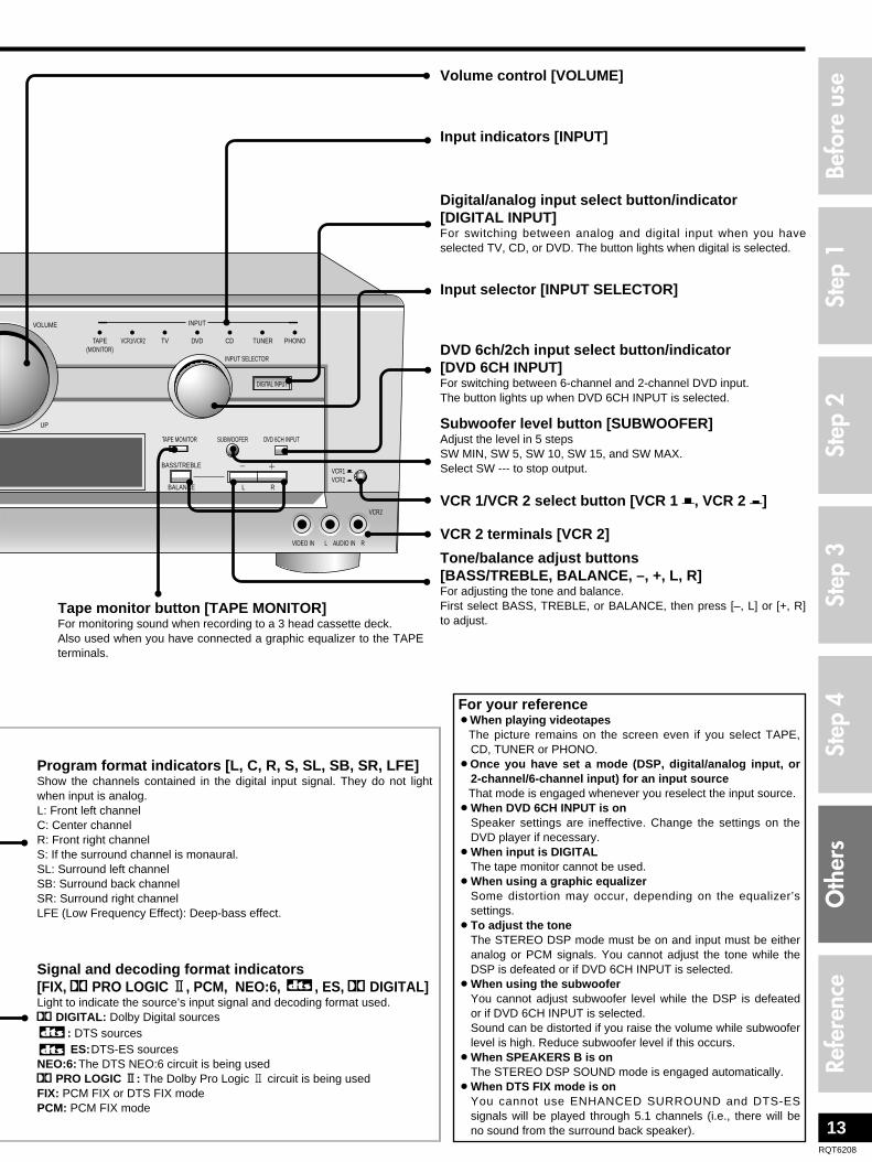
Volume control [VOLUME]
Input selector [INPUT SELECTOR]
Digital/analog input select button/indicator[DIGITAL INPUT]For switching between analog and digital input when you haveselected TV, CD, or DVD. The button lights when digital is selected.
Subwoofer level button [SUBWOOFER]Adjust the level in 5 steps SW MIN, SW 5, SW 10, SW 15, and SW MAX.Select SW --- to stop output.
DVD 6ch/2ch input select button/indicator[DVD 6CH INPUT]For switching between 6-channel and 2-channel DVD input.The button lights up when DVD 6CH INPUT is selected.
Tape monitor button [TAPE MONITOR]For monitoring sound when recording to a 3 head cassette deck.Also used when you have connected a graphic equalizer to the TAPEterminals.
Tone/balance adjust buttons[BASS/TREBLE, BALANCE, –, +, L, R]For adjusting the tone and balance.First select BASS, TREBLE, or BALANCE, then press [–, L] or [+, R]to adjust.
For your reference¡When playing videotapes
The picture remains on the screen even if you select TAPE,CD, TUNER or PHONO.
¡Once you have set a mode (DSP, digital/analog input, or2-channel/6-channel input) for an input sourceThat mode is engaged whenever you reselect the input source.
¡When DVD 6CH INPUT is onSpeaker settings are ineffective. Change the settings on theDVD player if necessary.
¡When input is DIGITALThe tape monitor cannot be used.
¡When using a graphic equalizerSome distortion may occur, depending on the equalizer’ssettings.
¡To adjust the toneThe STEREO DSP mode must be on and input must be eitheranalog or PCM signals. You cannot adjust the tone while theDSP is defeated or if DVD 6CH INPUT is selected.
¡When using the subwooferYou cannot adjust subwoofer level while the DSP is defeatedor if DVD 6CH INPUT is selected.Sound can be distorted if you raise the volume while subwooferlevel is high. Reduce subwoofer level if this occurs.
¡When SPEAKERS B is onThe STEREO DSP SOUND mode is engaged automatically.
¡When DTS FIX mode is onYou cannot use ENHANCED SURROUND and DTS-ESsignals will be played through 5.1 channels (i.e., there will beno sound from the surround back speaker).
Step
1St
ep 2
Step
3St
ep 4
Befo
re u
seO
ther
sRe
fere
nce
VCR 2 terminals [VCR 2]
VCR 1/VCR 2 select button [VCR 1 l, VCR 2 k]
Input indicators [INPUT]
Program format indicators [L, C, R, S, SL, SB, SR, LFE]Show the channels contained in the digital input signal. They do not lightwhen input is analog.L: Front left channelC: Center channelR: Front right channelS: If the surround channel is monaural.SL: Surround left channelSB: Surround back channelSR: Surround right channelLFE (Low Frequency Effect): Deep-bass effect.
Signal and decoding format indicators[FIX, % PRO LOGIC 22, PCM, NEO:6, , ES, % DIGITAL]Light to indicate the source’s input signal and decoding format used.% DIGITAL: Dolby Digital sources
: DTS sourcesES:DTS-ES sources
NEO:6: The DTS NEO:6 circuit is being used% PRO LOGIC 22: The Dolby Pro Logic 2 circuit is being usedFIX: PCM FIX or DTS FIX modePCM: PCM FIX mode

14RQT6208
Change this setting to listen to software recorded with Dolby Digitalat low volume (such as late at night) and maintain audio clarity. Itreduces the peak level in loud scenes without affecting the soundfield.OFF: The software is played with the original dynamic range
(factory setting).STANDARD: The level recommended by the producer of the
software for household viewing.MAX: The maximum allowable compression (recommended for
night viewing).
11 Press [ ] at the same time to enter thesetting mode.
22 Press [ ] to select “DR-COMP”.
33 Turn [ ] to select “OFF”, “STANDARD”
or “MAX”.
44 Press [ ] at the same time to exit thesetting mode.
SPEAKERSA B
INPUT SELECTOR
SPEAKERSA
SPEAKERSA B
Preset the stations one at a time.
11 Tune to the station.22 Press [ ].33 Press [ ] to select a channel.44 Press [ ].MEMORY
TUNING
2 1
MEMORY
11 Press [ ] to select “FM”.
22 Press [ ] to tune to “FM 87.9 MHz”.33 Press and hold [ ].
The FM stations the unit can receive are preset in channels 1 to 30.
44 Press [ ] to select “AM”.
55 Press [ ] to tune to “AM 530 kHz”.66 Press and hold [ ].
The AM stations the unit can receive are preset in channels 21 to 30.
(FM stations are replaced if any were preset in these channels.)
During automatic presetting, the memory indicator (˜) flashes andthe frequency scrolls. The memory indicator and channel numbersare displayed for a second when a station is preset.The last station to be preset is displayed when presetting finishes.
MEMORY
TUNING
2 1
- BAND– FM MODE
MEMORY
TUNING
2 1
- BAND– FM MODE
11 Press [ ].The channel number flashes for about 5 seconds.
22 Press [ ].Hold down the buttons to change channels faster.
For your referenceEven if the power supply cord is disconnected from the householdAC outlet, the stations remain in memory for approximately onemonth.
Improving reception¡ DSP DEFEAT
Press and hold [ ] until “DEFEAT” appears.
Press and hold [ ] again to turn the DSP on.
While the DSP is defeated, you cannot:– Select DSP sound modes,– Adjust the tone,– Output a test signal,– Adjust individual speaker output, or– Use digital input.
¡For your referenceDVD players can interfere with radio reception. Turn the DVDplayer off or move it further away from the antennas if this occurs.
Note
ENHANCED SURROUND
ENHANCED SURROUND
TUNING
2 1
PRESET
Presetting Other settings
DR COMP – Dynamic range compression
DIMMER – Dim the unit’s display for betterviewing in a darkened room
Automatic presetting
Manual presetting
Selecting channels
POWER
SPEAKERSA B
DOWN
DSP SOUND MODE
UP
TAPE(MONITOR)
TV DVD
INPUT
CD TUNER PHONOVCR1/VCR2
VOLUME
INPUT SELECTOR
DVD 6CH INPUTSUBWOOFERTAPE MONITOR
BASS/TREBLE 3 4
BALANCE L R
DIGITAL INPUT
PHONES
VIDEO IN
VCR2
L AUDIO IN R
- HELP– RESET
- BAND– FM MODE
VCR1 lVCR2 k
MEMORY ENHANCED SURROUND
TUNING
PRESET
NEO:6DOLBY
PRO LOGIC 2
8
2 1
TUNING MEMORY
PRESET
2 1
- BAND– FM MODE
ENHANCED SURROUND
POWER
SPEAKERSA B
DOWN
DSP SOUND MODE
UP
TAPE(MONITOR)
TV DVD
INPUT
CD TUNER PHONOVCR1/VCR2
VOLUME
INPUT SELECTOR
DVD 6CH INPUTSUBWOOFERTAPE MONITOR
BASS/TREBLE 3 4
BALANCE L R
DIGITAL INPUT
PHONES
VIDEO IN
VCR2
L AUDIO IN R
- HELP– RESET
- BAND– FM MODE
VCR1 lVCR2 k
MEMORY ENHANCED SURROUND
TUNING
PRESET
NEO:6DOLBY
PRO LOGIC 2
8
2 1
INPUT SELECTORSPEAKERS
A B
The factory setting is OFF (normal brightness).
11 Press [ ] at the same time to enter thesetting mode.
22 Press [ ] to select “DIMMER”.
33 Turn [ ] to select “OFF” or “ON”.
44 Press [ ] at the same time to exit thesetting mode.
SPEAKERSA B
INPUT SELECTOR
SPEAKERSA
SPEAKERSA B
A/D ATT – turn the A/D attenuator on if“OVER” lights frequently when using 2-channelanalog input
The factory setting is OFF.
11 Press [ ] at the same time to enter thesetting mode.
22 Press [ ] to select “A/D ATT”.
33 Turn [ ] to select “OFF” or “ON”.
44 Press [ ] at the same time to exit thesetting mode.
SPEAKERSA B
INPUT SELECTOR
SPEAKERSA
SPEAKERSA B

15RQT6208
L
R
L
R
FM ANT
AM ANT
GND
LOOP
EXT
75Ω
OUT IN
IN IN IN INOUTFRONT
OPTICAL1(CD) IN
OPTICAL2(TV) IN
OPTICAL3(DVD) IN
COAXIALIN
OPTICALOUT
SURROUND
6-8ΩEACH SPEAKER
CHAQUE
R L
DIGITAL
SUBWOOFER
COMPONENT VIDEO
TVMONITOR
OUTMONITOR
OUTY
R
L
PB
PR
DVD VCR1
PHONO TAPE VCR1CD TVDVD
GND
IN IN
CENTER
SUBWOOFER SURROUND
IN OUT
IN
IN
IN
IN OUT
TV TV TV
VIDEO
S-VIDEO
REC(OUT)
PLAY(IN)
BACK
DVD/DVD 6CH
SPEAKERSHAUT-PARLE
5–12 m
FM outdoor antenna¡Disconnect the FM indoor antenna.¡The antenna should be installed by a competent technician.¡Twist the coaxial cable’s shield braid firmly and connect it to the
GND terminal.
AM outdoor antenna¡Run a piece of vinyl wire horizontally across a window or other
convenient location.¡Leave the loop antenna connected.¡Disconnect the antenna when the unit is not in use. Do not use
the antenna during an electrical storm.
20 mm (25/32")
10 mm (3/8")
Shield braid
Core wire
FM outdoor antenna
75 Ω coaxial cable
You can record to a tape deck connected to TAPE REC (OUT), aVCR connected to VCR 1 OUT, or digital recording equipmentconnected to DIGITAL OPTICAL OUT.See the recording unit’s operating instructions for details on how toprepare it for recording.With a tape deck, you can record any analog source except TAPE.With a VCR, you can record any analog source except TAPE andVCR 1/VCR 2.With digital recording equipment, you can record any digital sourcewithout copy protection.
11 Turn [ ] to select the source to be
recorded.22 Begin recording.
Follow your recording unit’s operating instructions.
33 Start the source to be recorded.Follow your equipment’s operating instructions.
¡When you select DVD 6CH INPUT mode, only sound from thefront left and right channels is recorded.
¡Some sources do not allow digital recording. Connect through theanalog terminals and select “ANALOG” input.
Note
INPUT SELECTOR
Recording on other equipment
Making a recording Using outdoor antennas
Vinyl-covered wire
(16–40 ft)
Step
1St
ep 2
Step
3St
ep 4
Befo
re u
seO
ther
sRe
fere
nce
POWER
SPEAKERSA B
DOWN
DSP SOUND MODE
UP
TAPE(MONITOR)
TV DVD
INPUT
CD TUNER PHONOVCR1/VCR2
VOLUME
INPUT SELECTOR
DVD 6CH INPUTSUBWOOFERTAPE MONITOR
BASS/TREBLE 3 4
BALANCE L R
DIGITAL INPUT
PHONES
VIDEO IN
VCR2
L AUDIO IN R
- HELP– RESET
- BAND– FM MODE
VCR1 lVCR2 k
MEMORY ENHANCED SURROUND
TUNING
PRESET
NEO:6DOLBY
PRO LOGIC 2
8
2 1
INPUT SELECTOR
AM loop antenna (included)

16RQT6208
Troubleshooting guide
Before requesting service, make the below checks. If you are in doubt about some of the check points, or if the remedies indicated inthe chart do not solve the problem:In the U.S.A., contact the Panasonic Customer Call Center at 1-800-211-7262, or e-mail [email protected], or web site(http://www.panasonic.com).In Canada, contact Panasonic Canada Inc. Customer Care Centre at 905-624-5505, or web site (www.panasonic.ca), or an authorizedServicentre closest to you.
¡Connect the appropriate antenna. (You may need an outdoor antenna or onewith more elements.)
¡Adjust the position of the FM or AM antenna.¡Reduce the treble.¡Select “DSP DEFEAT”.¡Turn off nearby televisions, video decks, DVD players, and satellite receivers.¡Separate the antenna from other cables, leads, and appliances.
The radio cannot be tuned in orthere is a lot of noise andinterference.
7, 15
71314––
¡Ensure the SIZE settings for your speakers are correct.¡Check the DSP sound mode.¡Cancel “DSP DEFEAT”.
Sound is not heard from thecenter, surround, or subwooferspeakers.
8–91014
¡Ensure the SIZE settings for your speakers are correct.¡Turn ENHANCED SURROUND on.
Sound is not heard from thesurround back speaker.
8–910
¡Cancel “DSP DEFEAT”.¡Turn DVD 6CH INPUT off.
DSP sound modes cannot beselected.
1413
DSP sound modes Pages
Radio Pages
Common problems
¡Ensure the power cord is connected.No power.
¡Switch off the unit, determine and correct the cause, then switch the unit on. Causes include:
–Shorting (bare wires touching) of positive and negative speaker wires. –Using speakers with an impedance lower than that rated for this unit. –Straining of the speakers through excessive volume or power. –Using the unit in a hot environment without proper ventilation.
Sound stops. “OVERLOAD”appears on the display.
7
–
¡Turn the volume up.¡Check connections to speakers and other equipment.¡Turn on the speakers.¡Turn off the tape monitor.¡Select the correct source.¡Change the D-INPUT setting to suit the type of connection you have made.¡Check that the digital signals can be decoded by this unit.¡Turn PCM FIX or DTS FIX off.
No sound.
104–71013108–91010
54–5
––
¡Turn the unit off, disconnect the AC power supply cord, and consult yourdealer.
“F 70” appears on the display.
Pages
¡Cancel “DSP DEFEAT”.Cannot select “DIGITAL” input. 14

17RQT6208
Specifications (IHF’78)
AMPLIFIER SECTIONRated minimum sine wave RMS power output
40 Hz–20 kHz both channels driven0.9 % total harmonic distortion 100 W per channel (6 Ω)
1 kHz continuous power output both channels driven0.05 % total harmonic distortion 105 W per channel (6 Ω)
Total harmonic distortionrated power at 40 Hz–20 kHz 0.9 % (6 Ω)half power at 1 kHz 0.07 % (6 Ω)
Power output at 1kHz each channel driven0.9 % total harmonic distortion
Front (L, R) 100 W (6 Ω)Center 100 W (6 Ω)Surround (L, R, BACK) 100 W (6 Ω)
Low frequency damping factor 30 (6 Ω) Load impedance
Front (L, R)A or B 4–8 ΩA and B 8 Ω
Center 6–8 ΩSurround (L, R, BACK) 6–8 Ω
Dynamic headroom 2 dB (6 Ω) Frequency response
PHONO RIAA standard curve ±0.8 dBCD, TAPE, DVD, TV, VCR 1/VCR 2 10 Hz–70 kHz, ±3 dB
Input sensitivityPHONO 0.4 mV (3 mV, IHF ’66)CD, TAPE, DVD, TV, VCR 1/VCR 2 27 mV (200 mV, IHF ’66)
S/N (IHF A)PHONO 70 dB (80 dB, IHF ’66)CD, TAPE, DVD, TV, VCR 1/VCR 2 75 dB (85 dB, IHF ’66)DVD 6CH 100 dB (IHF A, Rated Power, S=2V)
85 dB (94 dB, IHF ’66)Input impedance
PHONO 47 kΩCD, TAPE, DVD, TV, VCR 1/VCR 2 22 kΩ
Tone controlsBASS 50 Hz, +10 to –10 dBTREBLE 20 kHz, +10 to –10 dB
Subwoofer frequency response (–6 dB) 7–200 Hz
Digital input Optical 3 Coaxial 1
Digital output Optical 1
FM TUNER SECTIONFrequency range 87.9–107.9 MHzSensitivity 11.2 dBf (2 µV, IHF ’58)50 dB quieting sensitivity
MONO 18.3 dBf (4.5 µV, IHF ’58)STEREO 38.3 dBf (45 µV, IHF ’58)
Total harmonic distortionMONO 0.2 %STEREO 0.3 %
S/NMONO 73 dBSTEREO 67 dB
Frequency response 20 Hz–15 kHz, +1 dB, –2 dBAlternate channel selectivity 65 dBCapture ratio 1.5 dBImage rejection at 98 MHz 40 dBSpurious response rejection at 98 MHz 75 dBAM suppression 50 dBStereo separation
1 kHz 40 dB10 kHz 30 dB
Antenna terminal 75 Ω (unbalanced)
AM TUNER SECTIONFrequency range 530–1710 kHzSensitivity 20 µV, 330 µV/mSelectivity 55 dBIF rejection at 1000 kHz 50 dB
VIDEO SECTIONOutput voltage at 1 V input (unbalanced) 1±0.1 Vp-pMaximum input voltage 1.5 Vp-pInput/output impedance 75 Ω
GENERALPower supply AC 120 V, 60 HzPower consumption 450 VA, 350 W Dimensions (W x H x D) 430 x 158 x 370 mm
(16-15/16'' x 6-7/32'' x 14-19/32'')Mass 10.5 kg (23.1 lb.)
Power consumption in standby mode: 1 W
Notes:1. Specifications are subject to change without notice.
Mass and dimensions are approximate.2. Total harmonic distortion is measured by the digital spectrum
analyzer.
Step
1St
ep 2
Step
3St
ep 4
Befo
re u
seO
ther
sRe
fere
nce
To clean this unit, wipe with a soft, dry cloth.¡Never use alcohol, paint thinner or benzine to clean this unit.¡Before using chemically treated cloth, read the instructions that
came with the cloth carefully.
If the surfaces are dirty
MaintenanceManufactured under license from Dolby Laboratories.“Dolby”, “Pro Logic” and the double-D symbol are trademarks ofDolby Laboratories.
Manufactured under license from Digital Theater Systems, Inc.US Pat. No. 5,451,942, 5,956,674, 5,974,380, 5,978,762 andother world-wide patents issued and pending.“DTS” , “DTS-ES Extended Surround” and “Neo:6” aretrademarks of Digital Theater Systems, Inc. Copyright 1996,2000 Digital Theater Systems, Inc. All rights reserved.

18RQT6208
Warranty (U.S.A.)
Panasonic Consumer Electronics Company, Division of Matsushita Electric Corporation of AmericaOne Panasonic Way Secaucus, New Jersey 07094
Panasonic/Technics Audio ProductsLimited Warranty
Panasonic Consumer Electronics Company or Panasonic Sales Company(collectively referred to as “the Warrantor”) will repair or replace this productwith new or refurbished parts or equivalent product, free of charge in theU.S.A. or Puerto Rico, in the event of a defect in materials or workmanshipas follows (all time periods commerce from the date of original purchase):AUDIO PRODUCTS–labor and parts for one (1) year.ALL AUDIO RACKS (cabinets)–parts only 30 days.TECHNICS STAND ALONE SPEAKERS, SUBWOOFER SPEAKERS–labor and parts for three (3) years.USB READER-WRITER, PERSONAL COMPUTER CARD ADAPTERS–(when applicable)–exchange defective unit with a new or refurbished onefor one (1) year.ACCESSORIES–HEADPHONES, CARTRIDGES, MICROPHONES,ADAPTERS–labor and parts for ninety (90) days.RECHARGEABLE BATTERIES–(when applicable)–exchange defectiveitem for new one for ten (10) days. Non-rechargeable batteries are notwarranted.SD MEMORY CARDS, RECHARGEABLE BATTERY PACK–(whenapplicable)–exchange defective item for new one for ninety (90) days. Non-rechargeable battery packs are not warranted.
Carry-in or mail-in service in the U.S.A. can be obtained during thewarranty period by contacting a Panasonic Services Company (PASC)Factory Servicenter listed in the Servicenter Directory. Or call toll free,1-800-211-7262 to locate a PASC authorized Servicenter. Carry-in or mail-inservice in Puerto Rico can be obtained during the warranty period by callingthe Panasonic Sales Company telephone number listed in the ServicenterDirectory.
This warranty is extended only to the original purchaser. A purchasereceipt or other proof of date of original purchase will be required beforewarranty service is rendered.
This warranty only covers failures due to defects in materials andworkmanship which occur during normal use and does not cover normalwear to the stylus (when applicable) or a dealer installed cartridge or stylus.The warranty does not cover damages which occur in shipment or failureswhich are caused by products not supplied by the warrantor, or failureswhich result from accident, misuse, abuse, neglect, mishandling, faultyinstallation, misapplication, set-up adjustments, maladjustment of consumercontrols, improper operation or maintenance, improper antenna, inadequatesignal reception or pick-up, alteration, modification, power line surge,improper voltage supply, lightning damage, commercial use, such as; hotel,office, restaurant, or other business or rental use of the product, or serviceby anyone other than a PASC Factory Servicenter or a PASC authorizedServicenter, or damage that is attributable to acts of God.
LIMITS AND EXCLUSIONSThere are no express warranties except as listed above.
THE WARRANTOR SHALL NOT BE LIABLE FOR INCIDENTAL ORCONSEQUENTIAL DAMAGES RESULTING FROM THE USE OF THISPRODUCT, OR ARISING OUT OF ANY BREACH OF THIS WARRANTY,INCLUDING WITHOUT LIMITATION, DAMAGE TO TAPES, RECORDSOR DISCS. ALL EXPRESS AND IMPLIED WARRANTIES, INCLUDINGTHE WARRANTIES OF MERCHANTABILITY, AND FITNESS FOR APARTICULAR PURPOSE, ARE LIMITED TO THE APPLICABLEWARRANTY PERIOD SET FORTH ABOVE. Some states do not allow theexclusion or limitation of incidental or consequential damages, or limitationson how long an implied warranty lasts, so the above exclusions orlimitations may not apply to you.
This warranty gives you specific legal rights and you may also have otherrights which vary from state to state.
If a problem with this product develops during or after the warrantyperiod, you may contact your dealer or Servicenter. If the problem is nothandled to your satisfaction, then write to the Consumer Affairs Departmentat the company address indicated above.
Panasonic Sales Company, Division of Matsushita Electricof Puerto Rico, Inc.Ave. 65 de Infantería, Km. 9.5San Gabriel Industrial Park, Carolina, Puerto Rico 00985
If you ship the product
Carefully pack and send it prepaid, adequately insured and preferably in the original carton.Attach a postage-affixed letter, detailing the complaint, to the outside of the carton.Do NOT send the product to the Executive or Regional Sales offices. They are NOT equipped to make repairs.
For product information or assistance with product operation:In the U.S.A., contact the Panasonic Customer Call Center at 1-800-211-7262, or e-mail [email protected], orweb site (http://www.panasonic.com).In Canada, contact Panasonic Canada Inc. Customer Care Centreat 905-624-5505, web site (www.panasonic.ca), or an authorizedServicentre closest to you.
Product information1. Damage requiring service — The unit should be serviced by
qualified service personnel if:(a) The AC power supply cord or the plug has been damaged; or(b) Objects or liquids have gotten into the unit; or(c) The unit has been exposed to rain; or(d) The unit does not operate normally or exhibits a marked
change in performance; or(e) The unit has been dropped or the cabinet damaged.
2. Servicing — Do not attempt to service the unit beyond thatdescribed in these operating instructions. Refer all otherservicing to authorized servicing personnel.
3. Replacement parts — When parts need replacing ensure theservicer uses parts specified by the manufacturer or parts thathave the same characteristics as the original parts.Unauthorized substitutes may result in fire, electric shock, orother hazards.
4. Safety check — After repairs or service, ask the servicer toperform safety checks to confirm that the unit is in properworking condition.
Product Service

19RQT6208
Servicenter List (U.S.A.)
Step
1St
ep 2
Step
3St
ep 4
Befo
re u
seO
ther
sRe
fere
nce

Panasonic Consumer ElectronicsCompany, Division of MatsushitaElectric Corporation of AmericaOne Panasonic Way Secaucus, New Jersey 07094http://www.panasonic.com
Panasonic Sales Company, Division of Matsushita Electric ofPuerto Rico, Inc. (“PSC”)Ave. 65 de Infantería, Km. 9.5 San Gabriel Industrial Park, Carolina, Puerto Rico 00985
Panasonic Canada Inc.5770 Ambler DriveMississauga, OntarioL4W 2T3www.panasonic.ca
En
2002 Matsushita Electric Industrial Co., Ltd. Printed in Malaysia
RQT6208-PH0202HM0
As an ENERGY STAR® Partner, Panasonichas determined that this product meets theENERGY STAR® guidelines for energyefficiency.
The model number and serial number of this product can befound on either the back or the bottom of the unit.Please note them in the space provided below and keep forfuture reference.
MODEL NUMBER ____________________________________
SERIAL NUMBER ____________________________________
DATE OF PURCHASE __________________________DEALER NAME _______________________________DEALER ADDRESS _________________________________________________________________________TELEPHONE NUMBER _________________________
User memo:
SA-HE100
CAUTION:This equipment has been tested and found to comply with thelimits for a Class B digital device, pursuant to Part 15 of theFCC Rules.These limits are designed to provide reasonable protectionagainst harmful interference in a residential installation. Thisequipment generates, uses and can radiate radio frequencyenergy and, if not installed and used in accordance with theinstructions, may cause harmful interference to radiocommunications. However, there is no guarantee thatinterference will not occur in a particular installation. If thisequipment does cause harmful interference to radio or televisionreception, which can be determined by turning the equipment offand on, the user is encouraged to try to correct the interferenceby one or more of the following measures:¡Reorient or relocate the receiving antenna.¡Increase the separation between the equipment and receiver.¡Connect the equipment into an outlet on a circuit different
from that to which the receiver is connected.¡Consult the dealer or an experienced radio/TV technician for
help.
Any unauthorized changes or modifications to this equipmentwould void the user’s authority to operate this device.
This device complies with Part 15 of the FCC Rules. Operationis subject to the following two conditions: (1) This device maynot cause harmful interference, and (2) this device must acceptany interference received, including interference that may causeundesired operation.
THE FOLLOWING APPLIES ONLY IN THE U.S.A.
CAUTION!DO NOT INSTALL, OR PLACE THIS UNIT, IN ABOOKCASE, BUILT-IN CABINET OR IN ANOTHERCONFINED SPACE. ENSURE THE UNIT IS WELLVENTILATED. TO PREVENT RISK OF ELECTRIC SHOCK ORFIRE HAZARD DUE TO OVERHEATING, ENSURE THATCURTAINS AND ANY OTHER MATERIALS DO NOTOBSTRUCT THE VENTILATION VENTS.
Selecting fine audio equipment such as the unit you’ve justpurchased is only the start of your musical enjoyment. Now it’s timeto consider how you can maximize the fun and excitement yourequipment offers. This manufacturer and the Electronic IndustriesAssociation’s Consumer Electronics Group want you to get the mostout of your equipment by playing it at a safe level. One that lets thesound come through loud and clear without annoying blaring ordistortion–and, most importantly, without affecting your sensitivehearing.
We recommend you to avoid prolonged exposure to excessivenoise.
Sound can be deceiving. Over time your hearing “comfort level”adapts to higher volumes of sound. So what sounds “normal” canactually be loud and harmful to your hearing.Guard against this by setting your equipment at a safe levelBEFORE your hearing adapts.To establish a safe level:¡Start your volume control at a low setting.¡Slowly increase the sound until you can hear it comfortably and
clearly, and without distortion.
Once you have established a comfortable sound level:¡Set the dial and leave it there.
Taking a minute to do this now will help to prevent hearingdamage or loss in the future. After all, we want you listening for alifetime.
EST. 1924
Listening caution


