Download - Autonomous buoy stations

Methods and instruments of Methods and instruments of the modern ocean researchthe modern ocean research
Alexander A. ParamonovAlexander A. ParamonovExperimental Design Bureau of Experimental Design Bureau of
Oceanological Engineering RAS, RussiaOceanological Engineering RAS, Russia

Modern scientific and technical methodology for marine Modern scientific and technical methodology for marine investigationinvestigation
The main attention is paid to:•the researches of seas surround countries; •the investigation and defense of the sea environment; rational use of biological, mineral and power resources;• the preservation of the recreation potential of the land and sea;•Intensification of the sea environment monitoring;•Forecasting of the extreme situations
Instrumentation and Technologies for the World Ocean Investigation-one of the major parts of the Federal Program of Russia “World Ocean”

Modern scientific and technical
methodology formarine investigation
The creation of long-term measuring systems on the large areas of the Ocean with use modern technologies and remote control measuring methods, transmission of information in the real-time mode is the actual problem today.
The methodology of ocean monitoring withuse onboard, underwater and satelliteinstruments supposes:
• Integrated application of multicomponent structure of satellite, over water and underwater scientific and technical instruments;
• Increase of the part of multifunction autonomous underwater systems for long-term continuous operation;
• Development perspective technology and methods of the remote control and information transfer in real time mode.

Multi component structure of the ocean monitoring
• I. АПК –AUS – autonomous underwater system
АБСАБС-- ABS ABS -- autonomous buoy station autonomous buoy station (mooring)(mooring)
АДБСАДБС--ADBSADBS--autonomous drifting autonomous drifting buoy stationbuoy station
АПДСАПДС-- AUDS AUDS -- autonomous drifting autonomous drifting buoy stationbuoy station--profile meterprofile meter
ДОДО –– OBO OBO –– ocean bottom observatoryocean bottom observatoryАДСАДС--OBS OBS ––ocean bottom stationocean bottom station• II. ПА-UV – deep water manned
and unmanned vehicles• III. АКС- ASS – aviation-satellite
system• IV. СК- SBS-shipboard System

Ocean environment research network
AOS
AUV
SatelliteLink Shore centerRV
HANS
Hydroacoustic/radio link
Hydroacoustic/radio link
Cable link

Autonomous ocean systems
Autonomous drifting Autonomous drifting stationsstations
Autonomous buoy Autonomous buoy stations (moorings)stations (moorings)
Ocean bottomOcean bottomobservatoriesobservatories
Ocean Autonomous Ocean Autonomous bottom stationsbottom stations

Oceanographic & hydroOceanographic & hydro--meteorological drifting station meteorological drifting station (drifters)(drifters)
Satellite drifter technology is rated now as one of most importaSatellite drifter technology is rated now as one of most important nt component of the global observing network of the ocean and component of the global observing network of the ocean and atmosphere.atmosphere.
Autonomous hydro meteorological drifting stations internationalAutonomous hydro meteorological drifting stations internationalprograms and projects:programs and projects:
•• World climate research program (WCRP);World climate research program (WCRP);•• World weather changeability program (WWW)World weather changeability program (WWW)•• Joint global ocean observation system (JGOSS);Joint global ocean observation system (JGOSS);•• International oceanographic data and information exchange International oceanographic data and information exchange
(IODE);(IODE);•• Global ocean observation system (GOOS);Global ocean observation system (GOOS);•• Global climate changeability observation system (GCOS).Global climate changeability observation system (GCOS).

Free drifting buoy stationFree drifting buoy stationInvestigation of nearInvestigation of near--water layer of atmosphere and sea surface layer.water layer of atmosphere and sea surface layer.
Buoy of SVP-B drifter.Measuring parameters:Measuring parameters:••speed and wind direction; speed and wind direction; ••temperature of the air; temperature of the air; ••temperature of the water in temperature of the water in ••the waterthe water--surface layer; surface layer; •• velocity and the direction of the surface velocity and the direction of the surface water flow; water flow; ••parameters of agitation; parameters of agitation; •• ecological parameters.ecological parameters.
Wind buoy
Places of drifting buoys starts (from July 1991)

Structure of the SVP drifter: Structure of the SVP drifter:
•• Electronic unitElectronic unit;;•• Water surface temperature sensorWater surface temperature sensor;;•• Atmosphere pressure sensorAtmosphere pressure sensor;;•• Power supply sensor (0 to 17 V Power supply sensor (0 to 17 V ±± 0,2 V);0,2 V);•• Sensor of the underwater position( diving) of Sensor of the underwater position( diving) of
the buoy (0 to 100% the buoy (0 to 100% ±± 3%);3%);•• Autonomous power supply unitAutonomous power supply unit;;•• Antenna Antenna •• Underwater sail, type Holey Underwater sail, type Holey --Sock with Sock with
center of pressure at the 15 m of the depthcenter of pressure at the 15 m of the depth
Free drifting buoy stationFree drifting buoy station
General arrangementof drifter“Holey-Sock”
Annual average estimations of the currentvelocity in 15 meter layer of the
Pacific ocean
In November 2004 Four SVP-BTC drifters have been deployed in the Black Sea..

Marlin-Yug SVP-B drifter
Subsurface temperaturesensor of SVP-BT drifter
SVP-BTC drifter
SVP Drifter - air/surface deployable autonomous buoy capable of operating unattended for periods of time up to 22 months.
•barometer,•subsurface temperature•temperature •chain up to 60 m depth)
ARGOS Platform Transmitter Terminals (PTT) MT105 A
SVP-B drifter at sea surface

Free drifting buoy stationFree drifting buoy station
General arrangementof wind buoy.
Drifting wind buoy structureDrifting wind buoy structure
••Air temperature sensorAir temperature sensor••Wind sensorWind sensor••Barometer with barometric portBarometer with barometric port••CompassCompass••Sensor of water surface Sensor of water surface temperaturetemperature••BatteryBattery of Power supplyof Power supply••Electronic unitElectronic unit••BuoyancyBuoyancy••SatelliteSatellite AntennaAntenna

Drifter profile meter type ARGO
Investigation of largeInvestigation of large--scale and low frequency changeabilityscale and low frequency changeability..of the of the upper active layer of the ocean.upper active layer of the ocean.
LongLong--term recorded parametersterm recorded parameters ::••Temperature; Temperature; ••electrical conductivity; electrical conductivity; ••the index of alkalinity; the index of alkalinity; ••the content of dissolved oxygen; the content of dissolved oxygen; ••the vector of subthe vector of sub--surface current.surface current.
”
Profile meter drifting station
••large number of submersionlarge number of submersion-- emersion cycles emersion cycles •• longlong--term observation of the currents term observation of the currents ••periodical measurements of the temperature and periodical measurements of the temperature and water saltiness profiles.water saltiness profiles.

General arrangement of Argo drifter
Profile meter driftingProfile meter drifting buoy basic structure buoy basic structure
Temperature sondeConductivity sondeSatellite receiving antenna &transmitter Air pumpStabilizerHydraulic pumpBattery supplyPressure sensorElectronic unit with satellite and data
telemetry subsystemgear-motor drive
Profile meter drifting station

Structure of the wave rider drifter: Sensors:•Atmosphere pressure,• Air temperature,• water temperature•depthSatellite navigating & measuring module: - The measurement of geographic coordinate, horizontal and vertical moving of the drifting buoy. -Wave registration- Transfer the data via satellite communication link
Two types of the EDB OE wave rider buoy-drifter design construction
Wave rider drifter:

Autonomous buoy stations (moorings) Autonomous buoy stations (moorings)
Hydro physical and hydrological investigation of the sea environHydro physical and hydrological investigation of the sea environment from the ment from the surface up to sea floor;surface up to sea floor;The study of largeThe study of large--scale, synoptic, smallscale, synoptic, small--scale changeability with time duration scale changeability with time duration from several days up to several years;from several days up to several years;
Autonomous buoy stations with surface main buoyAutonomous buoy stations with surface main buoyAutonomous buoy stations with subsurface main buoyAutonomous buoy stations with subsurface main buoyBottom buoy stationBottom buoy station
The advantage of current ASBS is the fast preparation for the scientific research task , taking into account the point of thedeployment, working depth, quantity of horizons, types of equipment, necessity of the positioning and so on.

Autonomous buoy stations (moorings) Autonomous buoy stations (moorings)
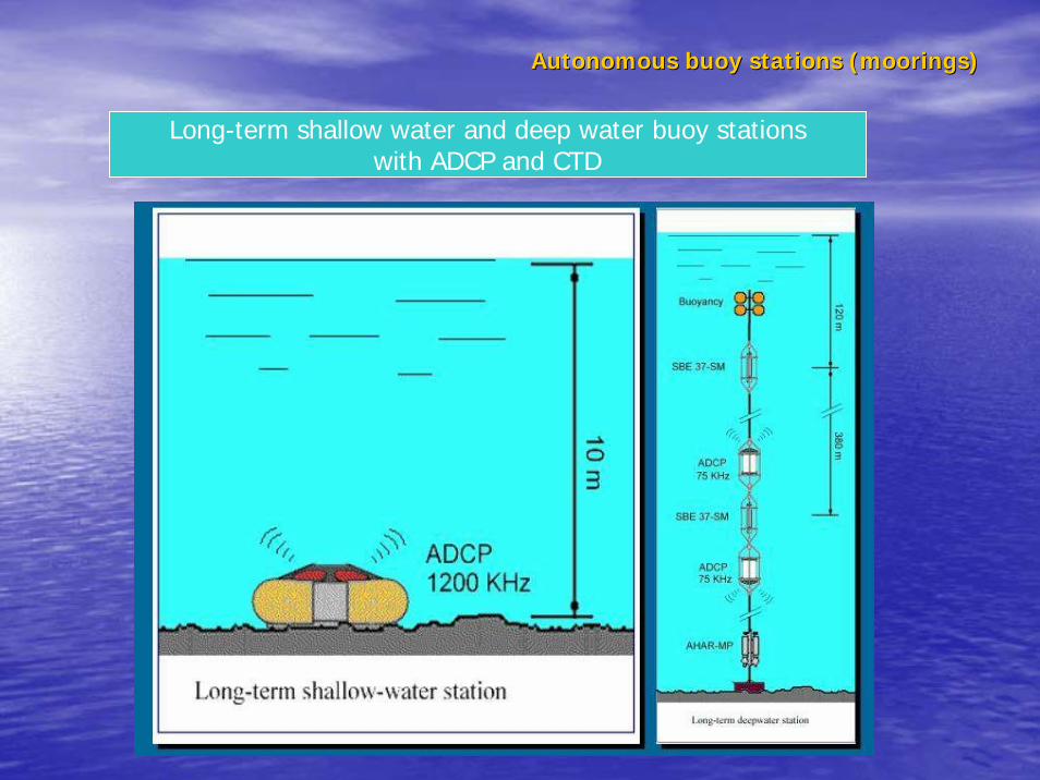
Structure of station:Structure of station:•• measuring devices measuring devices --current current
meters., sediment traps, CTD;meters., sediment traps, CTD;•• Double hydroacoustic release;Double hydroacoustic release;•• Anchor connected with rope Anchor connected with rope
through a hydroacoustic release; through a hydroacoustic release; •• Undersurface carrying buoy, Undersurface carrying buoy,
equipped radio and light beacons;equipped radio and light beacons;•• additional floats placed along additional floats placed along
rope;rope;•• Kevlar rope; Kevlar rope; •• the ship equipment for launch and the ship equipment for launch and
recovery and control of recovery and control of hydroacoustic release.hydroacoustic release.
Moorings with subsurface main buoy (ASBS).Moorings with subsurface main buoy (ASBS).

Shallow water mooring buoy stations
with current meters “Potok”
1. Float2. Current meter3. Hydroacoustic release with float4. Anchor
1- floats; 2 – current meters; 3 – release; 4 – sediment traps5 – anchor
.Deep-water ASBS ASBS mooringbuoy station
Autonomous buoy stations (mooringsAutonomous buoy stations (moorings))
Autonomous buoy stations (moorings)Autonomous buoy stations (moorings)
Long-term shallow water and deep water buoy stationswith ADCP and CTD

Bottom Measuring network of the bottom buoy stations with CTD and hydroacoustic transponders and cable communication link
Bottom buoy station

Current meters, type Current meters, type ““PotokPotok”” for mooring buoy stationfor mooring buoy station
Time averaging - 2-60 мин.
Current direction – 360 degree.Error - 5 degree
Temperature - -2 - +35 °CError - 0.035 °C
Conductivity - 0 - 2.5 s/м;Error - 0.005 s/м
Pressure, - up to 60 MПаError- 0.1%
Working depth, м,- up to 6000Current velocity, - cm/s 3-250Error - 2% Vmax ±2 сm/s
Operating time – up to 2 years

AHAR-ECShipboard electronic
AHAR-MP Shipboard electronic unit
Autonomous hydroacoustic transponderAutonomous hydroacoustic transponder--release release for mooring buoy stationsfor mooring buoy stations
"AHAR"AHAR--MPMP““ deepwaterdeepwater "AHAR"AHAR--ECEC““ shallow watershallow water

Specification:
AHAR-EC AHAR-MP1 Working depth, м 500 60002 Slant range of hydroacoustic communication,
м, 1000 8000
3 Frequency range, Hz 32.800-33.200 8 - 12.5
4 Number of channels of hydroacoustic control 90 1285 Power supply 9v 12v6 Operation life, month 6 127 Max. load, kg 50 20008 Dimensions, mm D70X165 D 130X
H5009 Weight :
-in air, kg-in water, kg
21
8.06
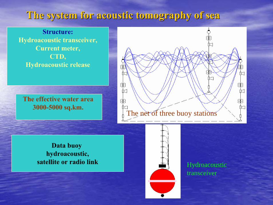
The system for acoustic tomography of seaThe system for acoustic tomography of sea
The net of three buoy stations
Structure:Hydroacoustic transceiver,
Current meter,CTD,
Hydroacoustic release
The effective water area 3000-5000 sq.km.
Data buoy hydroacoustic,
satellite or radio link Hydroacoustic transceiver
• Three dimensional visualization of marine media properties are performed during the passing through the system of synoptic eddies and other mezo-scale no uniformity (fronts, rings, current meanders): - sound velocity; - temperature; - density; - salinity; - flow velocity.
• The mechanisms of surface and submarine processes interaction could be known.
• The digital model of Sea area could be identified.
Another application of such system is as a part of integrated system of security of strategic and important economic sea underwater objects.
Application of such system - general coverage measurements of hydrophysical parameters inside a contour of the location of mooring stations using a method acoustic tomography.

OOcean bottom cean bottom stationsstations
• The ocean bottom seismic and acoustic stations with a broad-band frequency range are the most accessible instrument for research of seismic activity, ambient noise at ocean bottom and study of itsstructure.
• These stations are used for measurement and recording of seismic and acoustic signals in oceanic wave-guides propagation.
Autonomous bottom stations have applied importance, and are effectively used for seismic observation on oil and gas sea fields.

OBS terminologyOBS terminology•• OBS became the generic nameOBS became the generic name
Ocean Bottom SeismometerOcean Bottom SeismographOcean Bottom Station
•• PopPop--up Autonomous OBSup Autonomous OBSAutonomous OBSPop-up Autonomous OBSAutonomous Bottom Seismic Station - ABSS OBS only with hydrophone - OBH
•• Mooring OBSMooring OBSBottom seismograph - BS

OBS CLASSESOBS CLASSES
•• Mooring Mooring AdvantagesAdvantages
Easy to implementEasy to implementReliabilityReliabilityPossibility to transfer Possibility to transfer energy and dataenergy and data
DisadvantagesDisadvantages
Special ship equipment to Special ship equipment to deploydeployBuoBuoyyTotal equipment weightTotal equipment weightPiratesPirates
•• Autonomous Autonomous
No extra weight and No extra weight and volumevolumeMobile onboard Mobile onboard equipment to deployequipment to deploy
Special searching Special searching equipment on the sea equipment on the sea surfacesurfaceMore high risk of loss More high risk of loss

Mooring OBS deployment schemeMooring OBS deployment scheme

Developing New Generation of BroadbandOBS - BBOBS
• multi-purpose OBS. • broadband OBS - a broad passband and broad dynamic
range;• Operating time - up to one year with battery power supply;• Capacity to store, at least, a year's worth of data.
Thanks to recent advances in the computer technology and telecommunications industries, workable and inexpensive BBOBS may now be built.

Texas University New OBS Generation

Japan BB-OBS for long-term and broadband observations
The Earthquake Observation Center Ocean Hemisphere Research Center
long-term observation over one year conventional high-sensitivity OBS compact and reliablefour types of seismic sensorscontinuous recording use HDD 40

Germany• GEOMAR Technologie GmbH
(Kiel)21 OBS were used for gas hydrate’s
investigation in 2002 near Norway;Basic technical dataTitanium cylinder 172 mm
Max depth 6000 m
Operation time by power 20 days
Weight 240/300 kg
Seismic channels 4 (H, X, Y, Z)
Frequency range 4.5 Hz geophones
Dynamic range 16 – 24 bit
Sampling rate 0.1 – 16 ms
Power 1.5 w
Time check by GPS
Data carrier 4 PCMCIA 4 Gb
Operation mode continuous
Release electrochemikal acoustic
Compas 2-D

GEOMAR OBS on deck

OBS-net
Basic technical dataGlass spheres 430 mm
Max depth 6700 m
Operation time by power 20 days
Weight 45 \ 75kg?
Seismic channels 4 (H, X, Y, Z)
Frequency range 0.005 – 60 Hz?
Dynamic range 120db
Sampling rate 1 – 16 ms
Power 1.3 w
Time check by GPS
Data carrier 10 Gbyte HDD
Operation mode continuous, timer
event detectionRelease electrochemikal
acousticCompas 2-D
GeoPro (Hamburg) - 120 OBS.

GeoPro Twin-OBS
Operation time by power 6 month
Weight 90 \ 150kg

Micro OBS France (Ifremer&ORCA Instrumentation)
Basic technical dataGlass spheres 330 mm
Max depth 6000 m
Operation time by power 10 days
Weight 15 w/anchor
Seismic channels 4 (H, X, Y, Z)
Frequency range 4.5 Hz geophone Dynamic range 24 bits
Sampling rate 1 – 100 ms
Power 1.3 w
Time check by GPS
Data carrier Flash 1 GB
Operation mode continuous
Release integrated acoustic
electrochemikal

Russia, Experimental design bureau of oceanologicalengineering (EDBOE) RAS.
• constructed Aug. 2002 – Aug. 2003• Tested in Black Sea and
Mediterranean Sea.• Marine works in Mediterranean
Sea 2003, investigations of sediments and basement, 21 deployments.
• Marine works in Indian Ocean Nov. 2003 – Feb. 2004 , seismic investigations of crust structure.
101 deployments.
OBS type ABSS-1

ABSS-1 structure
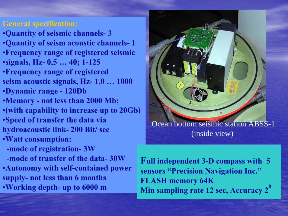
General specification:•Quantity of seismic channels- 3•Quantity of seism acoustic channels- 1•Frequency range of registered seismic•signals, Hz- 0,5 … 40; 1-125 •Frequency range of registeredseism acoustic signals, Hz- 1,0 … 1000 •Dynamic range - 120Db •Memory - not less than 2000 Mb; •(with capability to increase up to 20Gb) •Speed of transfer the data viahydroacoustic link- 200 Bit/ sec•Watt consumption: -mode of registration- 3W -mode of transfer of the data- 30W
•Autonomy with self-contained powersupply- not less than 6 months •Working depth- up to 6000 m
Ocean bottom seismic station ABSS-1(inside view)
Full independent 3-D compass with 5 sensors “Precision Navigation Inc.”FLASH memory 64K Min sampling rate 12 sec, Accuracy 20

Onboard hydro-acoustics equipment ABSS-1 system

ABBS-1 Digital recorder
• Analog to digit converter 24 bit• Sampling rate: 2, 4, 8, 16 ms• Station clock synchronization by GPS• Station clock time correction by temperature
dependence quartz oscillator• Data storage – FLASH memory 2HB (4HB) • Switch on/off by timer• Power consumption - 70mw• Battery 14 a h
Hydroacoustic Release
• Independent power supply• Electro-chemical wire melting in salt
waterTriggering by:- hydro-acoustics system (main mode)- emergency clock

Engineering service and ABSS-1 maintenance in marine expeditions
Preparation for the deployment
Deployment
The set of ABBS-1 Retrieval

OBS survey in Bay of Bengal & Arabian Sea
80 82 84 86 88 90 92
80 82 84 86 88 90 92
6
8
10
12
14
16
18
20
6
8
10
12
14
16
18
20
OBS profiles
OBS positions
SB stations
Moxo depth
No Moxo depth
P05
P04
P03
P02
P01
OBS lost
60 61 62 63 64 65 66 67 68 69 70 71 72 73 74 75
60 62 64 66 68 70 72 74
9
10
11
12
13
14
15
16
17
18
19
20
21
9
10
11
12
13
14
15
16
17
18
19
20
21
OBS profiles
OBS positions
SB stations
Moxo depthNo Moxo depthP06
P07P08
P09
P10
P11
P12
OBS lost

Record section Z-component
Vred = 8km/s
Vred = 6,8km/s

Autonomous Autonomous land & shelf seismic station land & shelf seismic station ARSSARSS--11
Frequency range 0,5 Hz - 40 HzSensitivity (F - 1 Hz) 0,4 х 10 -9 m/s
Dynamic range 110 DbRegistration time duration (4- channel) -20 days
Power consumption, W - 0,2
ADC Period, ms 16; 8; 4; 2Internal timer error 10-9
Max depth -20 мMemory ………512 Mb- 8 Gb

ARSSARSS--1 laboratory tests1 laboratory tests

Field works with ARSS-1 (May-June 2006)

PillarPillar
Tri-axial BB Sensor
Data Acquisition System • 6-Channel• 24-bit• 8MB RAM, 20GB hard disk
V-SATGPSantenna
IDU
S ERV ER 1
Ultra Enterpr ise 3000
S ERV ER 2
Ultra Enterpr ise 3000
S U N
W o rk Stat io n 1
U ltra 1
S U N W o rk St at io n 2
U ltr a 1
S U N W o rk St at io n 3
U ltr a 1
S U N W o rk St at io n 4
U ltr a 1
Sw itc h
Har d D i s k C LAR iiON
45 G B
MODE MMODE M
La ser Prin ter C o lo r
H P 5 M
La ser Prin ter
H P 400 0 1
Rem o te T elepho n e Access
IDU
Ethernet Switch
Primary data acquisitionComputer
Secondary data acquisitionComputer
Analysis Computer
Field Station
Power Supply unitfor DAS & Sensor
Power Supply unit for VSAT
Data flow from field stations.
DLT TapeLibrary (2TB)
Display Panel-2
Display Panel-1
B/W ColorPrinter
RAID level-5(512GB)
NSDC
GPS ReceiverMinimum 24 channel(L1+L2)
UPS
LOCAL TERMINAL ANDLASER JET PRINTER
CENTRALIZEDGPS TIMING
SYSTEM
Power Supply unitfor GPS Receiver
InformationDissemination System
SMSWebsiteEmailText to Voice

OceanOcean bottom geophysical observatory (OBO)bottom geophysical observatory (OBO)
OBO represents the set of unique oceanological measuring devices, structurally incorporated in a modular construction;
OBO is intended for:the study geophysical, geochemical processes at the ocean bottom area and continental shelf;for the implementation of fundamental researches of the near
bottom sea area;for the control and research of natural and anthropogenic extreme ecological situations in sea water areas and coastal zones (such as earthquakes, a tsunami).
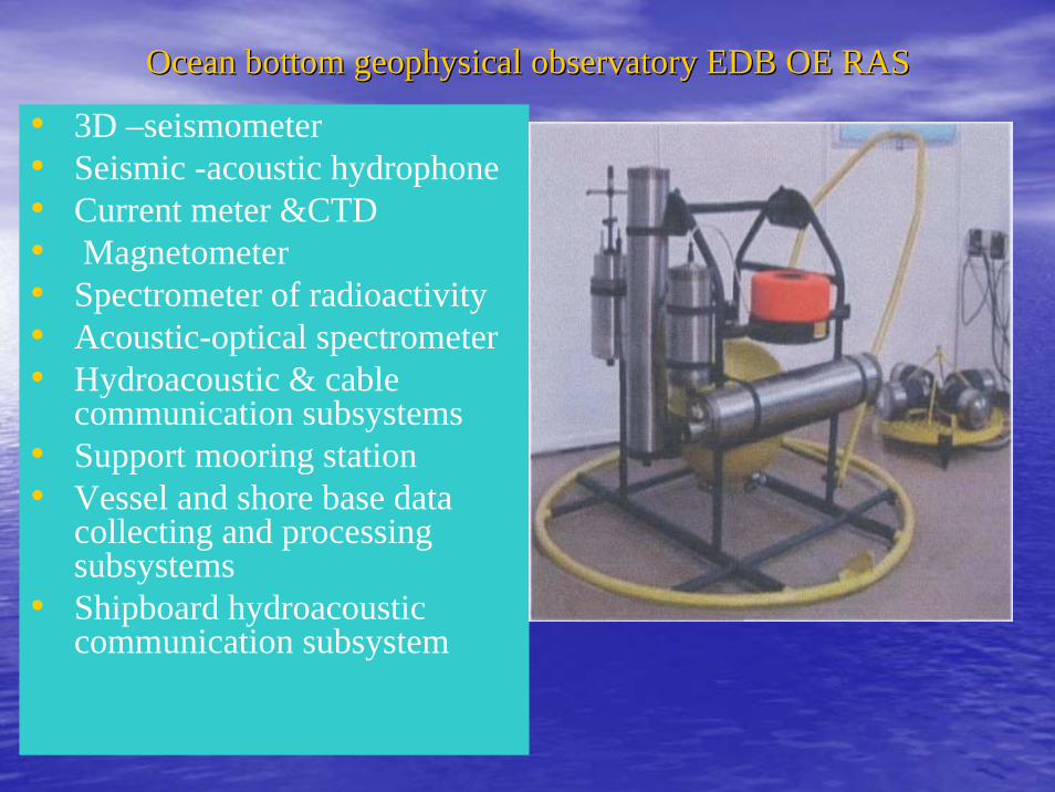
OceanOcean bottom geophysical observatory bottom geophysical observatory EDB OE RASEDB OE RAS
• 3D –seismometer • Seismic -acoustic hydrophone• Current meter &CTD• Magnetometer• Spectrometer of radioactivity• Acoustic-optical spectrometer• Hydroacoustic & cable
communication subsystems• Support mooring station • Vessel and shore base data
collecting and processing subsystems
• Shipboard hydroacoustic communication subsystem

OBO placement on the Sea bottom

3-D seismometer
Acoustic-optical spectrometer
Magnetic field sensor
Current meter & CTD
The OBO launching
OceanOcean bottom geophysical observatorybottom geophysical observatory (OBO)(OBO)

Data processing and control unit Hydroacoustic telemetry unit

OBO specificationOBO specification
• Frequency range of seismic signals, Hz , 0,03 – 40 (120 Db),• Frequency range of seismic-acoustic signals, Hz 1,0 – 1000 (80 Db), • Error of measurement of an azimuth angle 1degree• Basic error of measurement of current velocity,2% V• Basic error of measurement of current direction 2 degree• Range measuring of temperature, С, -2 - +32 • Basic error of measurement of temperature, C 0,01• Range measuring of pressure, Bar 1 - 600• Basic error of measurement of pressure 0,1%• Range of conductivity, sim/m 0,2 – 7,0 • Basic error of measurement, sim/m - 0,005

OBO specification (continuation)OBO specification (continuation)
• Range of a magnetic field measuring, nT 20000- 100000 • Basic error 1nT• Spectral range of underwater acoustic-optical spectrometer 415-
800 nм• Accuracy - 0,2 nм , Min time of sample 20 мс• Spectrometer of radioactive pollution, (type of the detector) NaI (Tl)• The range of registered scales – quantum 100 - 3000 keV• Minimum of detected activity of Cesium - 137 in sea water 3 - 5 Bq/m3• Capacity of the OBO memory 20 Gb• The quantity of the measuring channels simultaneously connected to
the block of registration up to 24• Accuracy of binding to system of uniform time 1мs
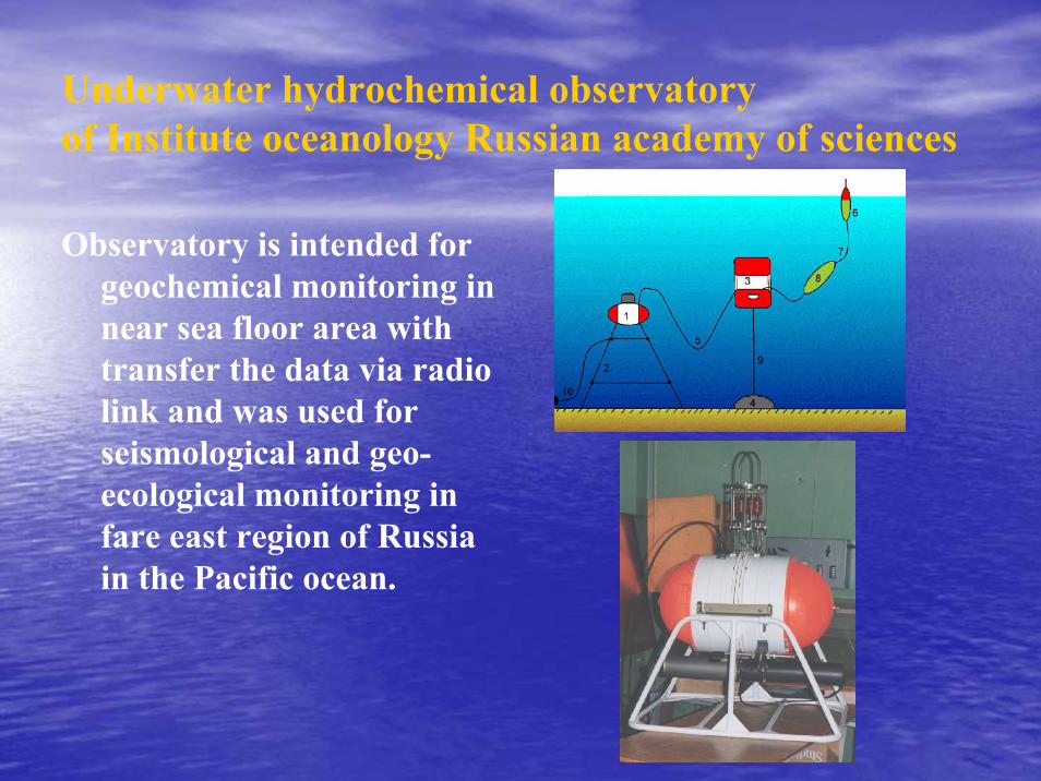
Underwater hydrochemical observatory of Institute oceanology Russian academy of sciences
Observatory is intended for geochemical monitoring in near sea floor area with transfer the data via radio link and was used for seismological and geo-ecological monitoring in fare east region of Russia in the Pacific ocean.

Underwater vehicle systems
Autonomous Underwater vehicles
Towed underwater vehicles
Remote operated vehicles
Manned submersibles
TV-photo TUV
Hydroacoustic TUV
Integrated TUV system
Observing shallow water ROV
Work class deepwater ROV
Mini & micro ROV
Deepwater MS
Shallow water & divers support MS

Autonomous unmanned underwater vehicle (AUV)Autonomous unmanned underwater vehicle (AUV)• The modern of autonomous multi-
purpose underwater vehicles represent new class of underwater robotics objects.
• AUV provides video and hydroacoustic observations of a sea-bottom, underwater objects in an automatic mode of motion and shooting according to the incorporated software of motion trajectory, the navigating data, and according to the commands of control, received by AUV via hydroacoustic link .
• The set of scientific equipment allows to carry out geotechnical monitoring according to the program of researches, which is programmed in the central processor of a control sub system of AUV before the start of works.
AUV “Tiflonus”,
AUV-OKPO-6000
AUV “Scarus“

AUV structure • Control, navigation & communication equipment; • Control system (loading of programs of work, their performance,
collection, processing and data record); • Onboard navigation system including the gauge of depth, magnetic or
gyroscopic compass, Doppler log, gauges of angular orientation, system of detour of obstacles;
• Hydroacoustic navigation system; • TV system of the identification of the object and orientation AUV
relatively it;• Hydrophysical and hydrochemical gauges• TV / photo system.• Sector scan sonar with an inclination of the diagram of an orientation
downwards for observation of the pipeline and revealing and measurement of deflection.
• Radio-light beacon (communication with the AUV and control its motion on a surface near to shore or support vessel).
• Emergency system
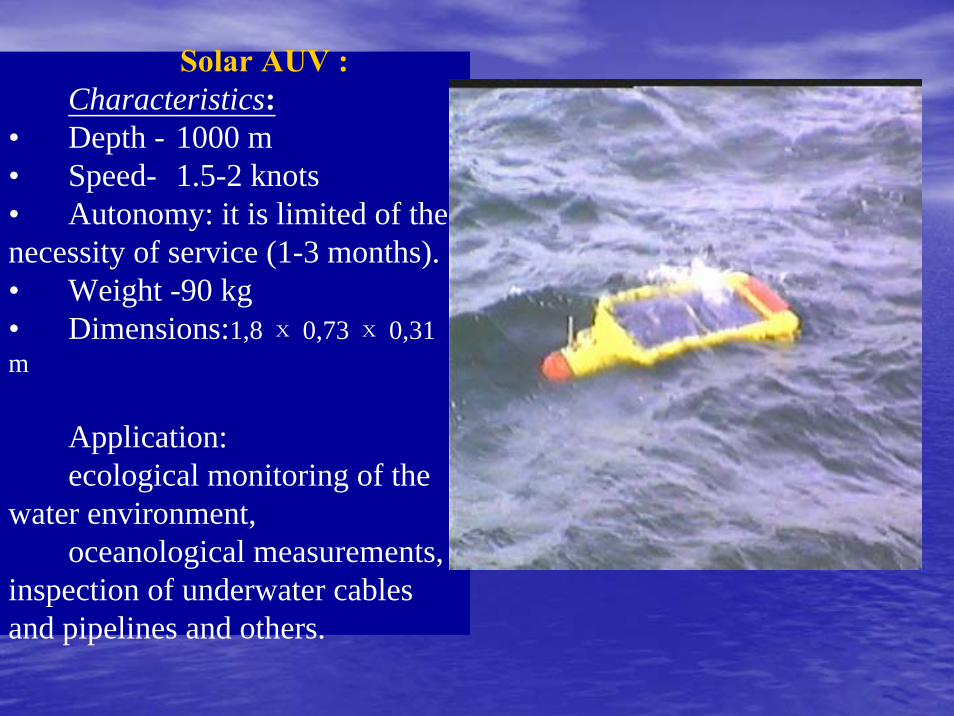
Solar AUV :Characteristics:
• Depth - 1000 m• Speed- 1.5-2 knots• Autonomy: it is limited of the necessity of service (1-3 months).• Weight -90 kg • Dimensions:1,8 х 0,73 х 0,31 m
Application: ecological monitoring of the
water environment, oceanological measurements,
inspection of underwater cables and pipelines and others.

Towed Towed vehiclesvehicles
Method of TFA-1 tow
Towed hydroacoustic & TVTowed hydroacoustic & TV--photo systemsphoto systems
TV-Photo vehicle TFA-1Observation of sea floor on the depth up to 6000m
Ship board equipment TFA-1
TFA-1A towed vehicle (front of view)

Side scan sonar towed systems
Side scan sonar MKSmain frequency - 240 kHz,range resolution - 0,3 m,maximum range - 150 m Echo sounder (optional)
main frequency - 190 kHz,transmit pulse duration - 0,5ms
General specification:survey velocity – up to 7 knots,
tow fish mass - 3 kg,electronic unit dimensions 65
х260х280 mmpower supply - 12 V, 50 W.
MKS equipment

System specification:main frequency– 78/82 kHz
maximum range (each board) – 1000mtransmitted pulse duration – 0.2/1.0 ms
directivity – 0.7x60ºSub bottom acoustical profiler:
main frequency – 4.5 kHztransmitted pulse duration – 0.25/0.5 ms
transmit pulse power – 2000 Wdirectivity - 50º
General specificationmaximum operating depth – up to 2000 m
tow cable length – up to 4000msurvey velocity – 2-5 knots
cable type – single ore coax electric wire
Side scan sonar MEZOSCAN
Towed Mezoscan system

Sub bottom profiler:main frequency – 4.5 kHz,transmit pulse power – 2000 Wtransmit pulse duration – 0.2/0.4/0.8 мсtransducer directivity - 60º,General specification:operational depth – up to 60 m,tow velocity – up to 7 knots,tow fish mass - 10 кг,electronic unit dimensions 60х260х310 mmpower supply including sub bottom profiler – 12V 500 W.
Side scan sonar MICROSOUND
System specification:Side scan sonar and echo sounder – the same as MKS
Side scan sonar MICROSOUND

Basic Structure:Side scan sonarBottom acoustic profilerMagnetometerTV-Photo systemCTD Echo sounderData telemetry sub systemPower supply Ship board control, data processing, visualization and data collecting subsystemHydroacoustic navigation subsystem
Deep water integrated towed system Deep water integrated towed system ““ZvukZvuk”” type.type.

RemoteRemote operated vehicle (ROVoperated vehicle (ROV))
• Now ROV systems became traditional and necessary underwater-technical instruments for the observation and providing multipurpose and hard underwater technical works.
• Modern ROV carries out not only direct visual control of underwater objects condition, but also it is equipped by devices for the control of a bottom surface (SS sonar, Multi beam echo sounder , seismic-profiler,) and by the different gauges for the providing wide range of various hydrophysical and geophysical, geochemical and hydroacoustic in-situ measurements in local area, first of all near sea floor.

Deep-water remote operatedvehicle (ROV) ROSUB -6000
• Specification: • ROV - Working depth of- 6000 m ; • Length - 2.4 m; Width - 1.8 m; Height - 1.6 m • Weight in air- no more than- 1500 kg,• Useful loading - 150 kg;,• 7-electric trasters; • Speed: forward- 3,5 knots; backward- 2,5 knots;
lateral and vertical- 1,5 knots.• Navigation structure: LBL/USBL navigation
system, inertial navigating system, DVL, echo-sounder, multi beam echo-sounder, sector scan sonar, depth meter.
• TV-photo - 1 color digital and 2 b/w high resolution TV cameras, 1 color digital photo camera, Lights - 4x500 Wт
• Manipulators: One 7 and one 5-degree of freedom electro-hydraulic manipulators, the set of the replaceable tools, system of automatic change of the tool and repetition of operator actions for approach to the given bottom point.
• Tether cable 400 m, used with cage.

Deep-water remote operatedvehicle (ROV) ROSUB -6000
Cage (Tether management system)• Working depth of 6000 m• Diameter -1.9 m• Height - 1.9 m • Weight in air no more than 1900 kg, • TV complex 1 color digital TV and
1 w/b photo camera • Lights - 2x500 Вт
• Cable winch - not less than 400 m.
ROV detaches from TMS
Tether management system ROSUB 6000

Deep-water remote operatedvehicle (ROV) ROSUB -6000
• The ship board equipment. • Launch &recovery system –
winch (capacity for 8km of FO cable), crane ( tonnage-12), high voltage electric power supply system, pilot, navigation, sonar, control consoles.
• The set of ship board equipment is placed in three containers with the sizes:
• Length - 6 m Width - 2, 5 m Height - 2,6 m Weight - no more than 12 т

Newest technologies of micro-ROV systems
Micro ROVs of “GNOM” family
The set of “GNOM -4-50” system
Super “GNOM-300”“GNOM 3-50” smallest type

Manned submersibles
Manned submersible “Argus” (1976)
Manned submersible- lockout “Osmotr” (1985)
Manned submersible “Mir-1”(1987)

Research vessel – the major component of Marine observing system
RV’s equipment for integrated experiments in the ocean:
Multi beam echo sounder system;Multi beam echo sounder system;Seismic profiler; Seismic profiler; Hydrological sonde with Hydrological sonde with
bathometer cassette;bathometer cassette;XBT & CTD systems;XBT & CTD systems;ADCP &DVL;ADCP &DVL;
Integrated satellite &hydroacoustic Integrated satellite &hydroacoustic navigation systemnavigation system;;DP system;DP system;Towed and remote operated underwater Towed and remote operated underwater
vehicles equipped by hydroacoustic and vehicles equipped by hydroacoustic and TVTV--photo systems;photo systems;
Hydro optical sondeHydro optical sonde ;;System of Geological & biological samplers ;System of Geological & biological samplers ;Meteorological measuring system ;Meteorological measuring system ;System for remote measurement the physical field parameters System for remote measurement the physical field parameters heterogeneity of upper ocean layer;heterogeneity of upper ocean layer;Radio and hydroacoustic communication systems;Radio and hydroacoustic communication systems;Satellite navigation system;Satellite navigation system;Satellite telecommunication Center;Satellite telecommunication Center;Data processing & collection softwareData processing & collection software--hardware system with Internet hardware system with Internet
Information Server;Information Server;Standard scientific laboratories equipped by research facilitieStandard scientific laboratories equipped by research facilities;s;

Special RV facilities for marine geological and geophysical,biological, ecological investigations.
•• Low background gamma spectrometers and betaLow background gamma spectrometers and beta--radiometers;radiometers;•• XX--ray fluorescence analyzerray fluorescence analyzer;;•• Immersion probing & towed deepwater gamma spectrometric detectorImmersion probing & towed deepwater gamma spectrometric detectors ;s ;•• Towed bottom profiler;Towed bottom profiler;•• Seismometer cable assemblies;Seismometer cable assemblies;•• Drags, dredges, corers, sampling tubes, plankton nets;Drags, dredges, corers, sampling tubes, plankton nets;•• FFiltration iltration and and sorptionsorption manifoldmanifolds for different purposes;s for different purposes;•• Special laboratory equipment ( centrifuges, thermostats, deepSpecial laboratory equipment ( centrifuges, thermostats, deep--freezers etc.)freezers etc.)

THANK YOU!!!THANK YOU!!!


