Stennis Space Center
Atmospheric Correction Prototype Algorithm for High Spatial Resolution Multispectral Earth
Observing Imaging Systems
Mary PagnuttiScience Systems and Applications, Inc.
John C. Stennis Space Center, MS 39529phone: 228-688-2135
e-mail: [email protected]
High Spatial Resolution Commercial Imagery WorkshopReston, Virginia, USANovember 10, 2004
November 10, 2004 2
Stennis Space Center
Contributors
NASA Applied Sciences Directorate, SSCTom Stanley Vicki Zanoni
Science Systems and Applications, Inc.Slawomir Blonski Kara HolekampKelly Knowlton Don PradosJeff Russell Robert Ryan
Lockheed Martin Space OperationsDavid Carver Jerry GasserRandy Greer Wes Tabor
This work was directed by the NASA Applied Sciences Directorate (formerly the Earth Science Applications Directorate) at the John C. Stennis Space Center, Mississippi. Participation in this work by Lockheed Martin Space Operations – Stennis Programs was supported under contract number NAS 13-650. Participation in this work by Computer Sciences Corporation and by Science Systems and Applications, Inc., was supported under NASA Task Order NNS04AB54T.

November 10, 2004 3
Stennis Space Center
Overview
• Objective– Evaluate accuracy of a prototype algorithm that uses satellite-
derived atmospheric products to generate scene reflectance maps for high spatial resolution (HSR) systems
• Approach– Implement algorithm in an end-to-end process– Compare algorithm generated scene reflectance maps with
ground-truth data– Identify algorithm sensitivities– Provide recommendations
• Constraints– Ground truth available only in VNIR spectral range
November 10, 2004 4
Stennis Space Center
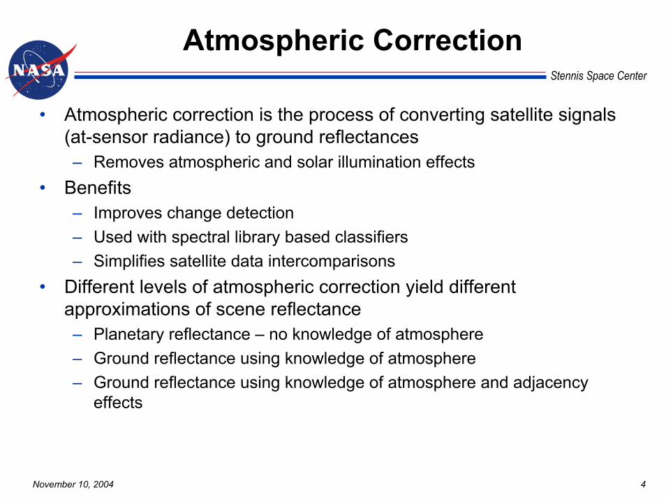
Atmospheric Correction
• Atmospheric correction is the process of converting satellite signals (at-sensor radiance) to ground reflectances– Removes atmospheric and solar illumination effects
• Benefits– Improves change detection– Used with spectral library based classifiers– Simplifies satellite data intercomparisons
• Different levels of atmospheric correction yield different approximations of scene reflectance– Planetary reflectance – no knowledge of atmosphere– Ground reflectance using knowledge of atmosphere – Ground reflectance using knowledge of atmosphere and adjacency
effects

November 10, 2004 5
Stennis Space Center
Planetary Reflectance
First-order approximation – no knowledge of atmosphere
2
cosd
EL sunp
TOA πθρ
=
distance Earth-Sunirradianceeric exoatmosph Solar
angle zenith Solarradiance sensor)-(at atmosphere of Top
ereflectancPlanetary :Where
==
==
=
dE
L
sun
TOA
p
θ
ρ
November 10, 2004 6
Stennis Space Center
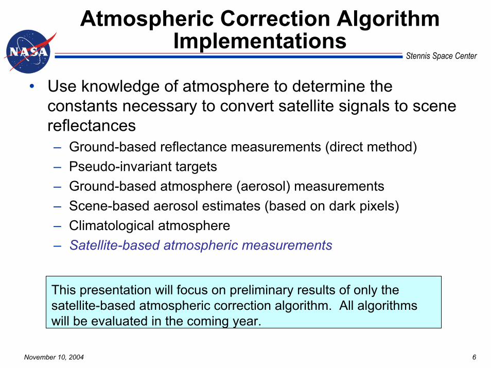
Atmospheric Correction Algorithm Implementations
• Use knowledge of atmosphere to determine the constants necessary to convert satellite signals to scene reflectances– Ground-based reflectance measurements (direct method)– Pseudo-invariant targets – Ground-based atmosphere (aerosol) measurements– Scene-based aerosol estimates (based on dark pixels)– Climatological atmosphere– Satellite-based atmospheric measurements
This presentation will focus on preliminary results of only the satellite-based atmospheric correction algorithm. All algorithms will be evaluated in the coming year.
November 10, 2004 7
Stennis Space Center
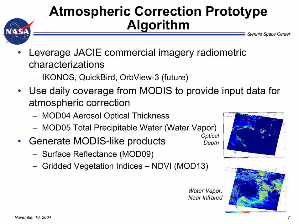
Atmospheric Correction Prototype Algorithm
• Leverage JACIE commercial imagery radiometric characterizations– IKONOS, QuickBird, OrbView-3 (future)
• Use daily coverage from MODIS to provide input data for atmospheric correction– MOD04 Aerosol Optical Thickness– MOD05 Total Precipitable Water (Water Vapor)
• Generate MODIS-like products– Surface Reflectance (MOD09) – Gridded Vegetation Indices – NDVI (MOD13)
Water Vapor,Near Infrared
OpticalDepth
November 10, 2004 8
Stennis Space Center
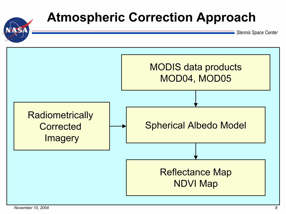
Atmospheric Correction Approach
MODIS data productsMOD04, MOD05
Spherical Albedo Model
Reflectance MapNDVI Map
Radiometrically Corrected Imagery
November 10, 2004 9
Stennis Space Center
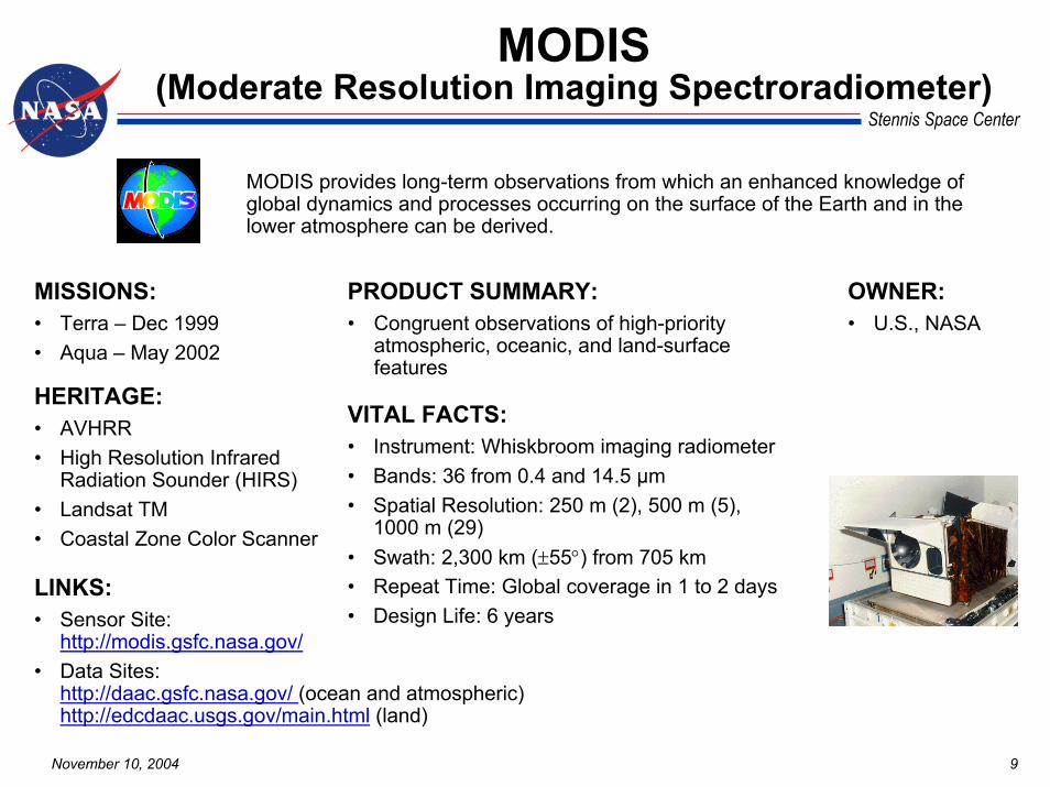
MODIS(Moderate Resolution Imaging Spectroradiometer)
VITAL FACTS:• Instrument: Whiskbroom imaging radiometer• Bands: 36 from 0.4 and 14.5 µm• Spatial Resolution: 250 m (2), 500 m (5),
1000 m (29)• Swath: 2,300 km (±55°) from 705 km• Repeat Time: Global coverage in 1 to 2 days• Design Life: 6 years
MISSIONS:• Terra – Dec 1999• Aqua – May 2002
MODIS provides long-term observations from which an enhanced knowledge of global dynamics and processes occurring on the surface of the Earth and in the lower atmosphere can be derived.
LINKS:• Sensor Site:
http://modis.gsfc.nasa.gov/• Data Sites:
http://daac.gsfc.nasa.gov/ (ocean and atmospheric)http://edcdaac.usgs.gov/main.html (land)
HERITAGE:• AVHRR• High Resolution Infrared
Radiation Sounder (HIRS)• Landsat TM• Coastal Zone Color Scanner
OWNER:• U.S., NASA
PRODUCT SUMMARY:• Congruent observations of high-priority
atmospheric, oceanic, and land-surface features
November 10, 2004 10
Stennis Space Center
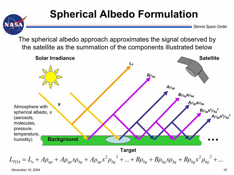
Spherical Albedo Formulation
The spherical albedo approach approximates the signal observed by the satellite as the summation of the components illustrated below
Target
Satellite
Background
Solar IrradianceL0
Bρbg
Aρtgt
s Aρtgtsρbg
Bρbgsρbg
Bρbgs2ρbg2
Aρtgts2ρbg2
Atmosphere with spherical albedo, s(aerosols, molecules,pressure, temperature, humidity)
...ρsBρsρBρBρ...ρsAρsρAρAρLL bgbgbgbgbgbgtgtbgtgttgtoTOA ++++++++= 2222
November 10, 2004 11
Stennis Space Center
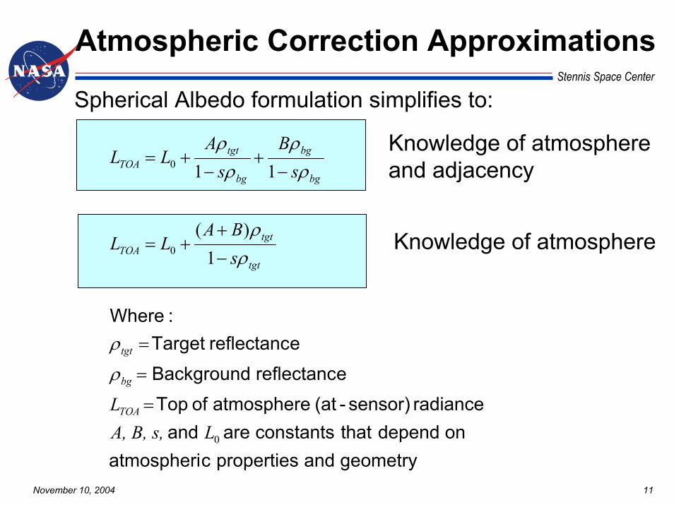
Atmospheric Correction Approximations
Spherical Albedo formulation simplifies to:
geometryandpropertiescatmospheriondependthatconstantsareand
radiance sensor)-(at atmosphere of TopereflectancBackground
ereflectanc Target:Where
0
0
0
1)(
11
LA, B, s,L
sBA
LL
sB
sA
LL
TOA
bg
tgt
tgt
tgtTOA
bg
bg
bg
tgtTOA
=
=
=
−
++=
−+
−+=
ρ
ρ
ρρ
ρρ
ρρ Knowledge of atmosphere
and adjacency
Knowledge of atmosphere
November 10, 2004 12
Stennis Space Center
Adjacency Effects
• Adjacency effects are caused by complicated multiple scattering in the atmosphere-land surface interactions– Dark pixels appear brighter and bright pixels appear darker– Significant in turbid atmospheres over highly heterogeneous
landscapes
• Different methods have been employed for removing this effect– Atmospheric point spread function-PSF (Environmental
Function)– Empirical formula

November 10, 2004 13
Stennis Space Center
Spherical Albedo Benefits
• Commonly used and found throughout the literature
• Allows for analytical determination of target albedo/reflectance values
• Computationally efficient
November 10, 2004 14
Stennis Space Center
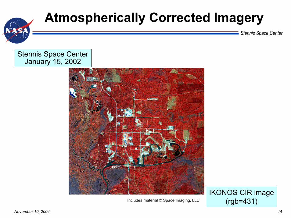
Atmospherically Corrected Imagery
IKONOS CIR image(rgb=431)
Stennis Space CenterJanuary 15, 2002
Includes material © Space Imaging, LLC
November 10, 2004 15
Stennis Space Center
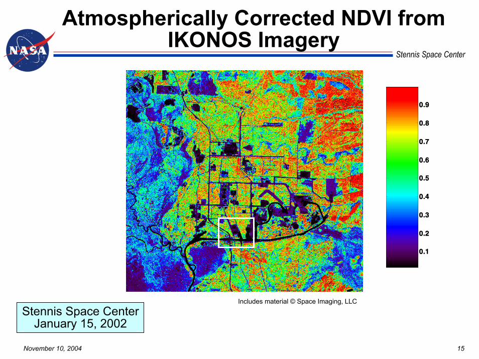
Atmospherically Corrected NDVI from IKONOS Imagery
Stennis Space CenterJanuary 15, 2002
Includes material © Space Imaging, LLC
0.1
0.2
0.3
0.4
0.5
0.6
0.7
0.8
0.9
0.1
0.2
0.3
0.4
0.5
0.6
0.7
0.8
0.9

November 10, 2004 16
Stennis Space Center
NDVI from IKONOS Imagery
Stennis Space CenterJanuary 15, 2002
Includes material © Space Imaging, LLC
0.1
0.2
0.3
0.4
0.5
0.6
0.7
0.8
0.9
0.1
0.2
0.3
0.4
0.5
0.6
0.7
0.8
0.9

November 10, 2004 17
Stennis Space Center
NDVI Histogram Comparison
-0.8 -0.6 -0.4 -0.2 0 0.2 0.4 0.6 0.80
100
200
300
400
500
600
700
800
900
1000
NDVI
Co
un
t
Tarp Site: Stennis Space CenterJanuary 15, 2002
Empirical line methodPlanetary reflectanceSpherical albedo w/adjacencySpherical albedoRadiance
Stennis Space Center
Atmospheric Correction Prototype Algorithm Verification
November 10, 2004 19
Stennis Space Center
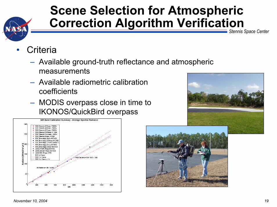
Scene Selection for Atmospheric Correction Algorithm Verification
• Criteria– Available ground-truth reflectance and atmospheric
measurements– Available radiometric calibration
coefficients– MODIS overpass close in time to
IKONOS/QuickBird overpass

November 10, 2004 20
Stennis Space Center
Selected Scene Matrix
Location Date HSR Sensor
SensorAz/El Ground Truth
SSC, MS Jan. 15, 2002 IKONOS 113.0 / 77.2
degTargets = 3 tarps (3.5, 22, 52), grass, concrete
ASD FieldSpec FR Spectroradiometer, ASR/MFRSR, pressure, radiosonde, BRDF
SSC, MS Feb. 17, 2002 IKONOS 100.7 / 81.9
degTargets = 3 tarps (3.5, 22, 52), grass, concrete
ASD FieldSpec FR Spectroradiometer, ASR/MFRSR, radiosonde, BRDF
SSC, MS Feb. 17, 2002 QuickBird 10.5 / 67.3
degTargets = 3 tarps (3.5, 22, 52), grass, concrete
ASD FieldSpec FR Spectroradiometer, ASR/MFRSR, radiosonde, BRDF
Brookings, SD July 20, 2002 QuickBird 349.8 / 64.1
degTargets = 2 tarps (3.5, 52), grass
ASD FieldSpec FR Spectroradiometer, ASR/MFRSR, radiosonde
Brookings, SD Sept. 7, 2002 QuickBird 191.0 / 74.9
degTargets = 2 tarps (3.5, 52), grass
ASD FieldSpec FR Spectroradiometer, ASR/MFRSR
SSC, MS Nov. 14, 2002 QuickBird 274.8 / 79.4
degTargets = 3 tarps (3.5, 22, 52), grass, concrete
ASD FieldSpec FR Spectroradiometer, ASR/MFRSR, pressure, radiosonde, BRDF
Brookings, SD Aug. 23, 2003 QuickBird 148.3 / 76.8
degTargets = grass
ASD FieldSpec FR Spectroradiometer, ASR/MFRSR
QuickBird
QuickBird
Brookings, SD Oct. 21, 2003
279.5 / 81.3 deg
Targets = grassASD FieldSpec FR Spectroradiometer, ASR/MFRSR
SSC, MS Jan. 10, 2004
230.7 / 89.2 deg
Targets = 4 tarps (3.5, 22, 34, 52), grass, concreteASD FieldSpec FR Spectroradiometer, ASR/MFRSR,
pressure, radiosonde

November 10, 2004 21
Stennis Space Center
Satellite Overpass Times
Location Date HSR Sensor
HSR Satellite Overpass Time
MODIS Overpass Time
SSC, MS Jan. 15, 2002 IKONOS 16:44 17:10
SSC, MS Feb. 17, 2002 IKONOS 16:47 16:14
SSC, MS Feb. 17, 2002 QuickBird 16:45 16:14
Brookings, SD July 20, 2002 QuickBird 17:26 17:42
Brookings, SD Sept. 7, 2002 QuickBird 17:22 16:47
SSC, MS Nov. 14, 2002 QuickBird 16:44 16:25
Brookings, SD Aug. 23, 2003 QuickBird 17:07 16:57
Brookings, SD Oct. 21, 2003 QuickBird 17:11 18:17
SSC, MS Jan. 10, 2004 QuickBird 16:30 17:27
November 10, 2004 22
Stennis Space Center
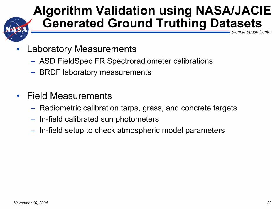
Algorithm Validation using NASA/JACIE Generated Ground Truthing Datasets
• Laboratory Measurements– ASD FieldSpec FR Spectroradiometer calibrations – BRDF laboratory measurements
• Field Measurements– Radiometric calibration tarps, grass, and concrete targets– In-field calibrated sun photometers– In-field setup to check atmospheric model parameters
November 10, 2004 23
Stennis Space Center
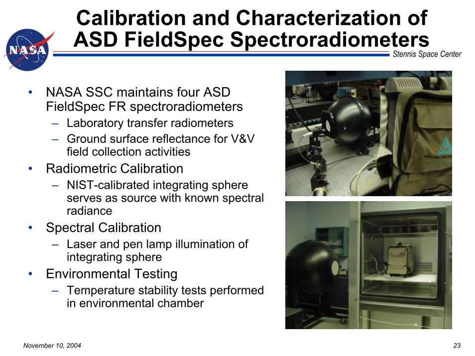
Calibration and Characterization of ASD FieldSpec Spectroradiometers
• NASA SSC maintains four ASD FieldSpec FR spectroradiometers– Laboratory transfer radiometers– Ground surface reflectance for V&V
field collection activities• Radiometric Calibration
– NIST-calibrated integrating sphere serves as source with known spectral radiance
• Spectral Calibration– Laser and pen lamp illumination of
integrating sphere• Environmental Testing
– Temperature stability tests performed in environmental chamber

November 10, 2004 24
Stennis Space Center
Laboratory BRDF Measurements
• Purpose– Laboratory BRDF measurements
are used to correct ground-based reflectance measurements for satellite viewing and for solar illumination geometry
• Method– Collimated FEL lamp source– NIST-calibrated Spectralon®
panel serves as reference– Goniometer-mounted sample
controls illumination geometry– Optronics OL750 hyperspectral
instrument measures spectra
Wavelength (nm)
Ref
lect
ance

November 10, 2004 25
Stennis Space Center
Algorithm Verification Case Matrix
• Three different atmospheric correction approximations– Case (1) Planetary reflectance– Case (2) Spherical albedo w/knowledge of atmosphere– Case (3) Spherical albedo w/knowledge of atmosphere &
adjacency• Three different sets of data used as input into
approximation– Case (a) ground based-sun photometer (aerosol), TOMS
(ozone), Radiosonde (water vapor)– Case (b) MOD04 (aerosol), TOMS (ozone), Radiosonde (water
vapor) – Case (c) MOD04 (aerosol), MOD05 (water vapor), TOMS
(ozone) Operational Case• Nine different scenes
Planetary Spherical Albedo Spherical Albedo w/adjacency
9 cases (1) + 17 cases (2b/2c) + 20 cases (3a/3b/3c) = 46 cases
November 10, 2004 26
Stennis Space Center
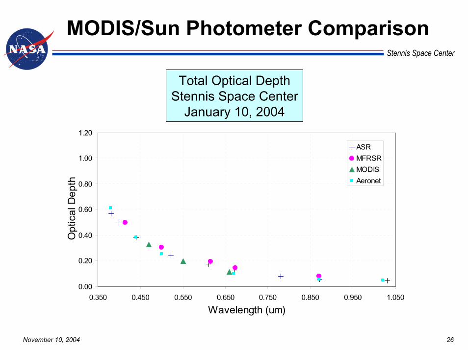
MODIS/Sun Photometer Comparison
Total Optical DepthStennis Space Center
January 10, 2004
0.00
0.20
0.40
0.60
0.80
1.00
1.20
0.350 0.450 0.550 0.650 0.750 0.850 0.950 1.050
Wavelength (um)
Opt
ical
Dep
th
ASRMFRSRMODISAeronet
November 10, 2004 27
Stennis Space Center
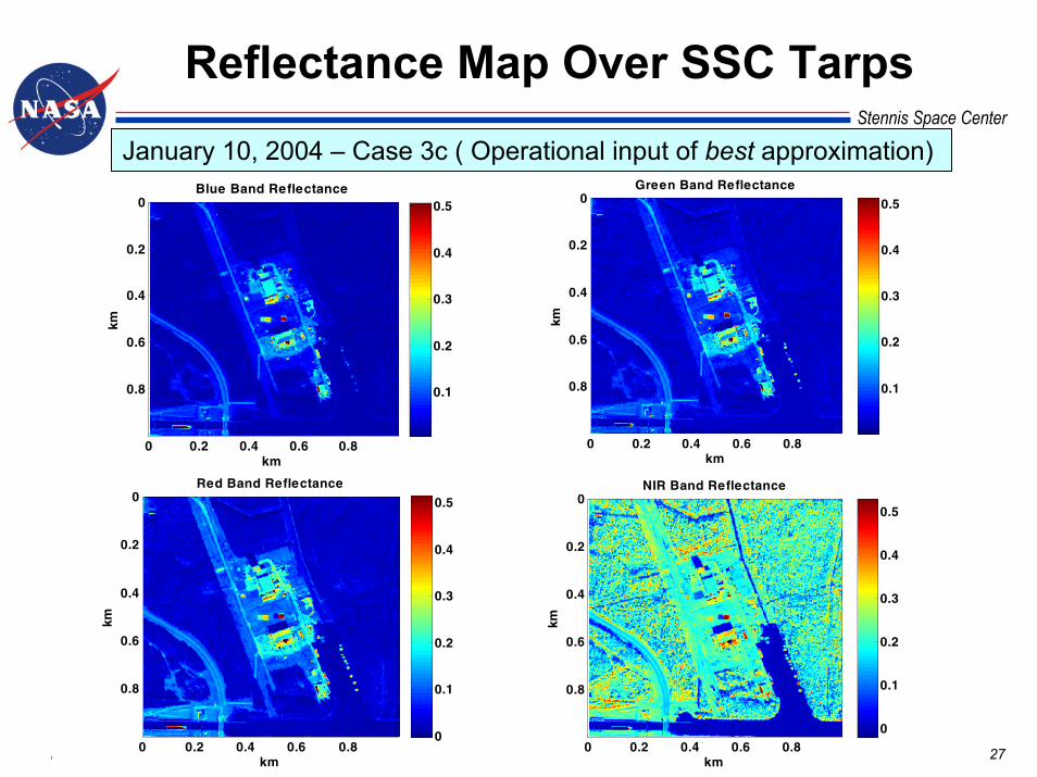
Reflectance Map Over SSC Tarps
January 10, 2004 – Case 3c ( Operational input of best approximation)
km
km
Blue Band Reflectance
0 0.2 0.4 0.6 0.8
0
0.2
0.4
0.6
0.8 0.1
0.2
0.3
0.4
0.5
km
km
Green Band Reflectance
0 0.2 0.4 0.6 0.8
0
0.2
0.4
0.6
0.8 0.1
0.2
0.3
0.4
0.5
km
km
Red Band Reflectance
0 0.2 0.4 0.6 0.8
0
0.2
0.4
0.6
0.8
0
0.1
0.2
0.3
0.4
0.5
km
km
NIR Band Reflectance
0 0.2 0.4 0.6 0.8
0
0.2
0.4
0.6
0.8
0
0.1
0.2
0.3
0.4
0.5
November 10, 2004 28
Stennis Space Center
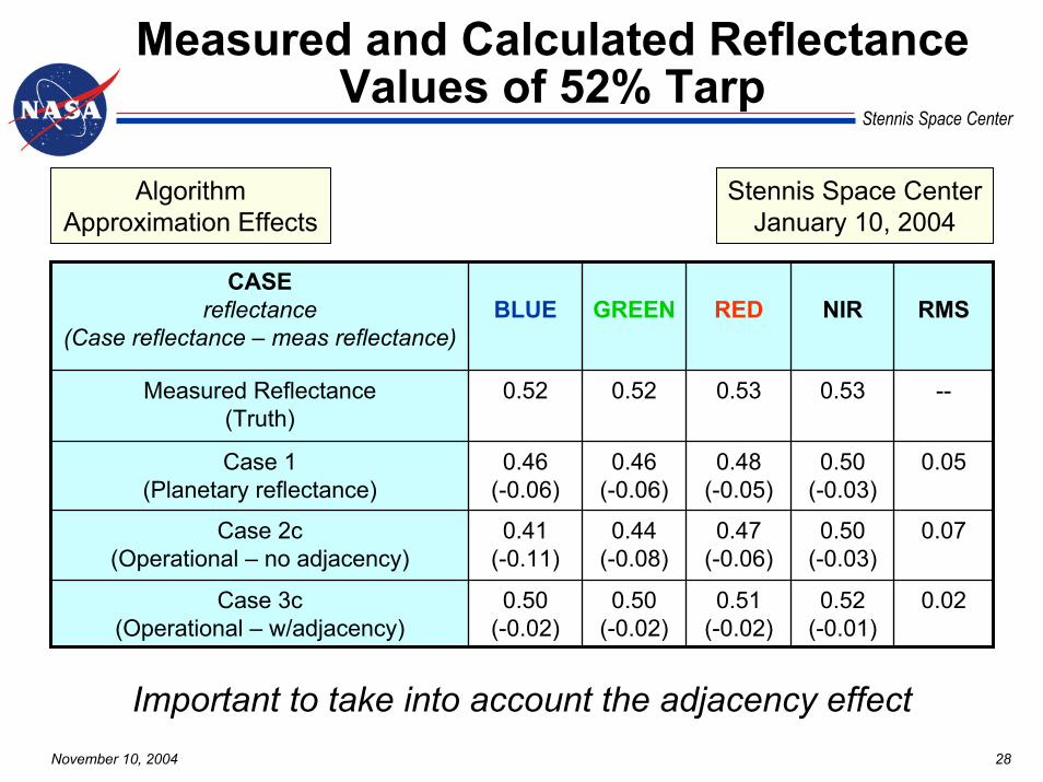
Measured and Calculated Reflectance Values of 52% Tarp
Algorithm Approximation Effects
Stennis Space CenterJanuary 10, 2004
CASEreflectance
(Case reflectance – meas reflectance)BLUE GREEN RED NIR RMS
Measured Reflectance(Truth)
0.52 0.52 0.53 0.53 --
Case 1(Planetary reflectance)
0.46(-0.06)
0.46(-0.06)
0.48(-0.05)
0.50(-0.03)
0.05
Case 2c(Operational – no adjacency)
0.41(-0.11)
0.44(-0.08)
0.47(-0.06)
0.50(-0.03)
0.07
Case 3c(Operational – w/adjacency)
0.50(-0.02)
0.50(-0.02)
0.51(-0.02)
0.52(-0.01)
0.02
Important to take into account the adjacency effect
November 10, 2004 29
Stennis Space Center
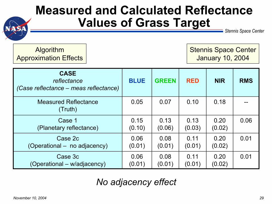
Measured and Calculated Reflectance Values of Grass Target
Algorithm Approximation Effects
Stennis Space CenterJanuary 10, 2004
CASEreflectance
(Case reflectance – meas reflectance)BLUE GREEN RED NIR RMS
Measured Reflectance(Truth)
0.05 0.07 0.10 0.18 --
Case 1(Planetary reflectance)
0.15(0.10)
0.13(0.06)
0.13(0.03)
0.20(0.02)
0.06
Case 2c(Operational – no adjacency)
0.06(0.01)
0.08(0.01)
0.11(0.01)
0.20(0.02)
0.01
Case 3c(Operational – w/adjacency)
0.06(0.01)
0.08(0.01)
0.11(0.01)
0.20(0.02)
0.01
No adjacency effect
November 10, 2004 30
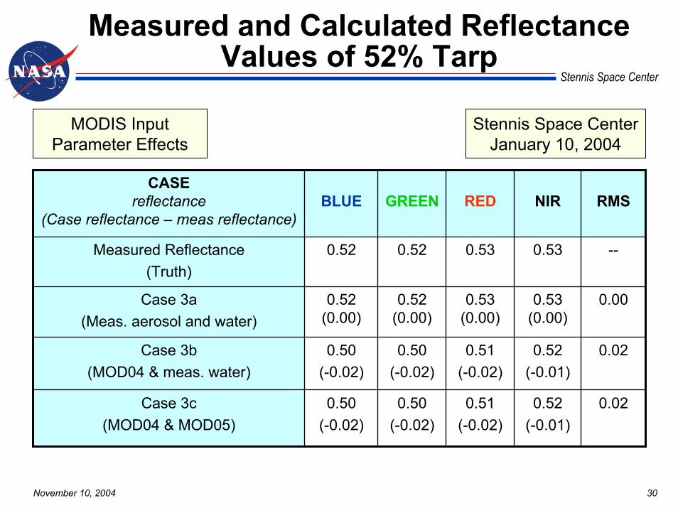
Stennis Space Center
Measured and Calculated Reflectance Values of 52% Tarp
MODIS Input Parameter Effects
Stennis Space CenterJanuary 10, 2004
CASEreflectance
(Case reflectance – meas reflectance)BLUE GREEN RED NIR RMS
Measured Reflectance(Truth)
0.52 0.52 0.53 0.53 --
Case 3a(Meas. aerosol and water)
0.52(0.00)
0.52(0.00)
0.53(0.00)
0.53(0.00)
0.00
Case 3b(MOD04 & meas. water)
0.50(-0.02)
0.50(-0.02)
0.51(-0.02)
0.52(-0.01)
0.02
Case 3c(MOD04 & MOD05)
0.50(-0.02)
0.50(-0.02)
0.51(-0.02)
0.52(-0.01)
0.02
November 10, 2004 31
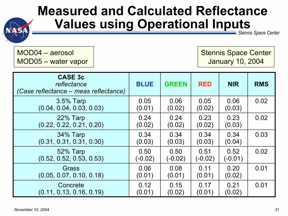
Stennis Space Center
Measured and Calculated Reflectance Values using Operational Inputs
MOD04 – aerosolMOD05 – water vapor
Stennis Space CenterJanuary 10, 2004
CASE 3creflectance
(Case reflectance – meas reflectance)BLUE GREEN RED NIR RMS
3.5% Tarp(0.04, 0.04, 0.03, 0.03)
0.05(0.01)
0.06(0.02)
0.05(0.02)
0.06(0.03)
0.02
22% Tarp(0.22, 0.22, 0.21, 0.20)
0.24(0.02)
0.24(0.02)
0.23(0.02)
0.23(0.03)
0.02
34% Tarp(0.31, 0.31, 0.31, 0.30)
0.34(0.03)
0.34(0.03)
0.34(0.03)
0.34(0.04)
0.03
52% Tarp(0.52, 0.52, 0.53, 0.53)
0.50(-0.02)
0.50(-0.02)
0.51(-0.02)
0.52(-0.01)
0.02
Grass(0.05, 0.07, 0.10, 0.18)
0.06(0.01)
0.08(0.01)
0.11(0.01)
0.20(0.02)
0.01
Concrete(0.11, 0.13, 0.16, 0.19)
0.12(0.01)
0.15(0.02)
0.17(0.01)
0.21(0.02)
0.01

November 10, 2004 32
Stennis Space Center
Operational Algorithm Verification Summary (Case 3c)
Location Date Sensor Average RMS for all targets
SSC, MS Jan. 15, 2002 IKONOS 0.02
SSC, MS Feb. 17, 2002 IKONOS 0.04
SSC, MS Feb. 17, 2002 QuickBird 0.01
Brookings, SD July 20, 2002 QuickBird 0.01
Brookings, SD Sept. 7, 2002 QuickBird 0.02
Brookings, SD Aug. 23, 2003 QuickBird 0.00
Brookings, SD Oct. 21, 2003 QuickBird 0.02
SSC, MS Jan. 10, 2004 QuickBird 0.02
November 10, 2004 33
Stennis Space Center
Summary/Future Direction
• MODIS products (MOD04, MOD05) provide the necessary inputs to generate high-spatial-resolution reflectance products under many conditions– Average RMS differences range between 0.00–0.04 for the eight
datasets evaluated (Case 3c-Operational input to best approximation)
• Adjacency can be an important component that needs to be accounted for to minimize errors
• Future Activities/Recommendations– Evaluate alternate algorithms– Compare algorithm results to MODIS products (MOD09,
MOD13)– Compare algorithm results to commercial atmospheric correction
algorithm results (FLAASH, ACORN, ATCOR …)


