Arc Flash Hazard Calculations – What does it
all mean?Robert E. Fuhr, P.E.PowerStudies, Inc.

Why are Arc Flash Hazard Studies Needed?
To Increase Electrical Safety at your facility!
Required by National Electric Code (NEC) and OSHA
To Protect You!


OSHA Requirements Standard 29 CFR 1910 Subpart S, 1910 to
1910.335 Must identify all hazards above 50 Volts Must put safeguards in place for these
hazards Must train employees on safe work
practices OSHA will fine you if you do not use NFPA
70E and there is an injury investigation.

Employers must provide workers with appropriate PPE as per the OSHA 29 1910.132 (h)(1) PPE payment requirement, i.e., (PPE) used to comply with this part, shall be provided by the employer at no cost to employees. Paragraph (h) became effective February 13, 2008, and employers must implement the PPE payment requirements no later than May 15, 2008

Key References in NEC ® -2017
110.16(A) General - Electrical equipment, such as switchboards, switchgear, panelboards, industrial control panels, meter socket enclosures, and motor control centers, that is in other than dwelling units, and is likely to require examination, adjustment, servicing, or maintenance while energized,

NEC 110.16 (continued)
….shall be field or factory marked to warn qualified persons of potential electric arc flash hazards.

NEC 110.16 (continued)
The marking shall meet the requirements in 110.21(B) and shall be located so as to be clearly visible to qualified persons beforeexamination, adjustment, servicing, or maintenance of the equipment.

NEC 110.16 (continued)
(B) - In other than dwelling units, in addition to the requirements in (A), a permanent label shall be field or factory applied to service equipment rated 1200 amps or more. The label shall meet the requirements of 110.21(B) and contain the following information:

NEC 110.16 (continued)
(1) Nominal system voltage(2) Available fault current at the service overcurrent protective devices(3) The clearing time of service overcurrent protective devices based on the available fault current at the service(4) The date the label was applied
Exception: Service equipment labeling shall not be required if an arc flash label is applied in accordance with acceptable industry practice.

NEC 110.16 (continued)
Informational Notes No. 1 & 3 Point to NFPA-70E for guidance as to how to determine the values & information to put on the labels.

NFPA 70E -Flash Hazard Analysis 130.5(A) General. An arc flash risk
assessment shall be performed:– (1) To identify arc flash hazards– (2) To estimate the likelihood of occurrence of
injury or damage to health and the potential severity of injury or damage to health
– (3) To determine if additional protective measures are required, including the use of PPE

NFPA 70E -Flash Hazard Analysis 130.5(F) Arc Flash PPE. One of the
following methods shall be used for the selection of arc flash PPE:
– (1) The incident energy analysis method in accordance with 130.5(G)
– (2) The arc flash PPE category method in accordance with 130.7(C)(15)** - Use with extreme caution!!!
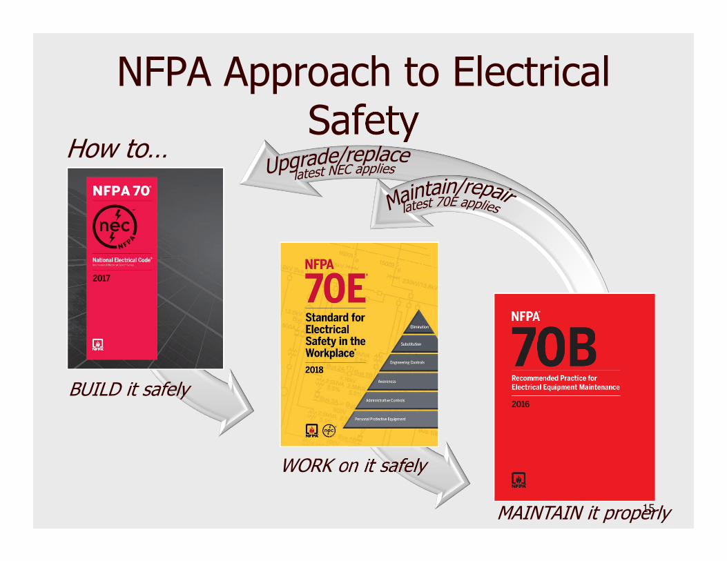
NFPA Approach to Electrical Safety
BUILD it safely
WORK on it safely
MAINTAIN it properly
How to…
15

Arc Flash Hazard Analysis Key Steps
Use NFPA 70E* Tables, IEEE 1584, Arc Pro, or Lee Equations to Determine – Incident energy levels – Arc Flash hazard boundary
* Use with extreme caution!

Arc Flash Hazard Analysis Key Steps
Use – Calculated Incident
Energy– NFPA 70E Table
130.5(G)– to determine
Required PPE

NFPA 70E –Arc Flash Labeling 130.5(H) Equipment Labeling. Electrical
equipment such as switchboards, panelboards, industrial control panels, meter socket enclosures, and motor control centers that are in other than dwelling units and that are likely to require examination, adjustment, servicing, or maintenance while energized shall be marked with a label containing all the following information:
REF3

Slide 18
REF3 Start here.Robert E Fuhr, 3/22/2018

NFPA 70E –Arc Flash Labeling(1) Nominal system voltage(2) Arc flash boundary(3) At least one of the following:
a. Available incident energy and the corresponding working distance, or the arc flash PPE category in Table 130.7(C)(15)(a) or Table 130.7(C)(15)(b) for the equipment, but not both.b. Minimum arc rating of clothingc. Site-specific level of PPE

NFPA 70E –Arc Flash Labeling The data shall be reviewed for accuracy at
intervals not to exceed 5 years. – (Arc Flash Refresher Study)
The owner of the electrical equipment shall be responsible for the documentation, installation, and maintenance of the marked label.

Informative Label

Informative Label

Short CircuitFault Study
Coordination (PDC)Study
Arc Flash StudyDevice Operating Time
Arcing Fault Current
3 Phase BoltedFault Current
Arc Flash LabelEnergy Level @ Working
DistanceAF & Shock Boundaries
Required PPE
Obtain EquipmentNameplate Data
& Settings

Arc Flash Hazard Analysis Key Steps
Determine:– Bolted Fault Currents (Short Circuit
Study)– Arcing Fault (AF) Current– Upstream Protective Device Clearing
Times (PDC Study) using AF
REF5

Slide 24
REF5 StartRobert E Fuhr, 3/22/2018

Arc Flash Hazard Analysis Key Steps
Calculate Arc Flash EnergyUse NFPA 70E Tables to determine:
– Glove Rating Class – Limited Approach Boundary– Restricted Approach Boundary – Required PPE

Arc Flash Hazard Analysis Key Steps
Arc Flash Warning Labels showing the details.

Informative Label

How a Short Circuit Study is Performed
Obtain distribution system nameplate data for:– Transformers– Motors– Circuit breakers, fuses, relays– Switchgear– Motor Control Centers– Conductor sizes and lengths

How a Short Circuit Study is Performed
Enter data into the computer program.
Simulate short circuit at each location and calculate the fault current.
Compare calculated fault current to equipment short circuit rating.

What is Protective Device Coordination (PDC) Study?
Determines:– fuse sizes– Settings for relays
and circuit breakers– Device operating
time The study has 2
conflicting goals

Goal #1 - Maximum Selective Coordination Between Equipment
Correct fuse sizes and settings will allow the device closest to a fault to trip.
If the first device fails to operate, then the next upstream device will trip.
Longer device trip delays = increased device coordination= greater incident energy

Selective Coordination 3-MSWBD MAIN
SWBD
XFMR-UTILSS
P 2- XFMR-UTILS
5-Fdr to ATS-E
6-PNL-A MAIN
PNL-A - 250 A
E NATS 260 Amp
1
2
3

Goal #2 - Maximum Equipment Protection and Reduction in Arc
Flash Energy Correct fuse sizes and device settings will
quickly interrupt the fault current for a short circuit downstream.
Shorter device delays = decreasedequipment damage = less Incident Energy

Maximum Equipment Protection
(No Selective Coordination)
3-MSWBD MAIN
SWBD
XFMR-UTILSS
P 2- XFMR-UTILS
5-Fdr to ATS-E
6-PNL-A MAIN
PNL-A - 250 A
E NATS 260 Amp
1
1
1

Must balance these two conflicting goals based upon the type of facility.

PDC Vocabulary Time Current Curve (TCC) Log-log graph of time versus current Every breaker, fuse, and relay has a
time current characteristic curve.

PDC Vocabulary
Selective Device Coordination– The devices plotted on the time current
curves are coordinated for all levels of fault current and time.


Fuse TCC
3-6 Sec
5 kA
@15 kAThis Fuse is Current Limiting –Clearing time is 0.004 seconds


Thermal Magnetic Trip Unit Thermal
Unit is Fixed
Instant-aneous– Fixed– Adjustable

Thermal Magnetic Breaker
20 kA0.01-0.025 Sec
4 kA
20-50 Sec


Solid State Trip
Unit SQ D NW
40H 4000 Amp Micrologic
Current SensorsRating Plugs
Current Setting

Solid State Trip
Unit Varies for
each Trip Unit!
Some Functions are Not Adjustable!
Long Time Pickup (LTPU)
Long Time Delay (LTD)
Short Time Pickup (STPU)
Short Time Delay (STD)
Instantaneous (I)
Short Time Delay I2T-IN
(I2T)

Solid State Trip
SQ D NW 40H
4000 Amp Micrologic
100 kA
0.01-0.06 Sec
6 kA
0.08-0.12 Sec 30 kA
170-210 Sec

Time Current Curves An example
of a TCC with Coordinated Devices
Current in Amperes X 100

Arc Flash Energy Calculations Incident Energy Levels are dependent on:
– Level of arcing fault current– Upstream device clearing time.
Multiple Sources

Typical Assumptions for an Analysis
Trip time is determined by the upstream protective device settings.
Worker is stationary. The maximum time that a worker will be
exposed to the arc flash is 2.0 seconds. (Depends upon location!!!)

Current Vs Energy LevelsFault Current vs. Incident Energy (Time Constant @ 0.025 Sec)
0 0 0
1 1 1 1 1 1 1
0
1
2
3
4
0 20 40 60 80 100
Fault Current
Inci
dent
Ene
rgy
Energy PPE Class

Time Vs Energy LevelsTime vs. Incident Energy (Fault Current Constant @ 30 kA)
1 1 1 2 2 3 3 3 40
10
20
30
0 0.1 0.2 0.3 0.4 0.5 0.6Device Operating Time
Inci
dent
Ene
rgy
Incident Energy PPE Class

Distance Vs Energy LevelsDistance vs. Incident Energy
(Time Constant @ 0.5 Sec & Fault = 60 kA)
0
124+ 34
01020304050
0 50 100 150 200 250
Distance (Inches)
Inci
dent
Ene
rgy
Energy Class

Arc Flash Warning LabelsWhat does it mean?

Informative Label

Limited Approach Boundary: An approach limit at a distance from an
exposed energized electrical conductor or circuit part within which a shock hazard exists.
This value is determined by NFPA 70E Table 130.4(D)(a).
Qualified Persons Unqualified if accompanied by a Qualified
Persons

Restricted Approach Boundary
An approach limit at a distance from an exposed energized electrical conductor or circuit part within which there is an increased likelihood of electric shock, due to electrical arc-over combined with inadvertent movement.
Determined by NFPA 70E Table 130.4(D)(a)

Arc Flash Label Installation Always clean the surface with detergent to
remove all grease and dirt. Wipe surface dry before applying the label.
Some locations will have a Line Side Label. They should be installed at locations where maintenance staff could be exposed to energized parts on the line side of a fuse or circuit breaker. Examples of this are Main Breakers in Switchboards and Switchgear.

Arc Flash Label Installation Transformer Labels are for small
distribution transformers (480/208 V) where both the 480 and 208 Volts terminals are exposed.
Locations where the label will be exposed to direct sun light should be brought to the attention of PowerStudies, Inc. We will provide labels with a special UV protective covering to protect the label from fading.

Line Side vs Bus AF Labels

Need more Information www.powerstudies.com
– Articles– Links– Specifications for Power System Studies Short Circuit Protective Device Coordination Arc Flash Hazard
Phone: 253-639-8535 Email: [email protected] or

Thank you for your time! Questions?????


