
Ho | 1
Appendix to “Networking VxWorks Real-Time
Kernel” by
Ngan Nguyen Huynh, Raymond Ho
Remote Data Acquisition with VxWorks
Raymond Ho
Instructor: Dr. Janusz Zalewski
04/25/2014
A1. Overview of Previous Project
In the previous semester’s project, time was spent on developing a VxWorks platform for
remote data acquisition (DAQ) and experimentation, running on a single board computer
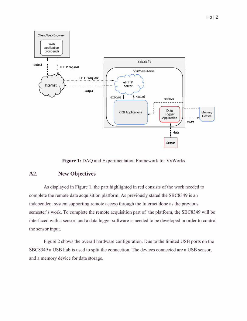
SBC8349 [1]. As displayed in Figure 1, the platform developed consists of a HTTP server, CGI
application and a memory device. The HTTP server provides web pages and CGI support for
users to navigate to and conduct experiments, such as a user uploading a VxWorks RTP
executable and running it remotely on the SBC8349. The ability for a user to upload and run the
VxWorks executables is provided by the developed CGI scripts. Furthermore, the result data of
the experiments, CGI scripts, HTTP server executable, and web resources are stored on the
memory device interfaced to the SBC8349. Thus the developed framework creates an
independent system for remote data acquisition and experimentation.
Ho | 2
Figure 1: DAQ and Experimentation Framework for VxWorks
A2. New Objectives
As displayed in Figure 1, the part highlighted in red consists of the work needed to
complete the remote data acquisition platform. As previously stated the SBC8349 is an
independent system supporting remote access through the Internet done as the previous
semester’s work. To complete the remote acquisition part of the platform, the SBC8349 will be
interfaced with a sensor, and a data logger software is needed to be developed in order to control
the sensor input.
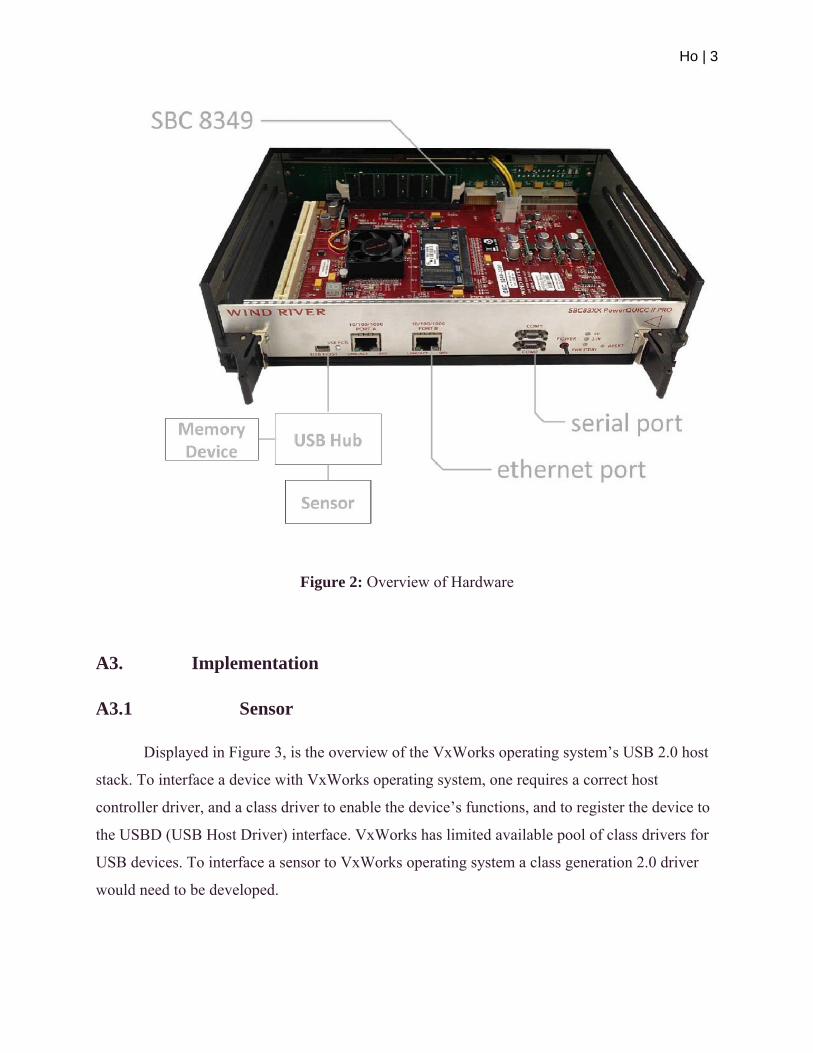
Figure 2 shows the overall hardware configuration. Due to the limited USB ports on the
SBC8349 a USB hub is used to split the connection. The devices connected are a USB sensor,
and a memory device for data storage.
Ho | 3
Figure 2: Overview of Hardware
A3. Implementation
A3.1 Sensor
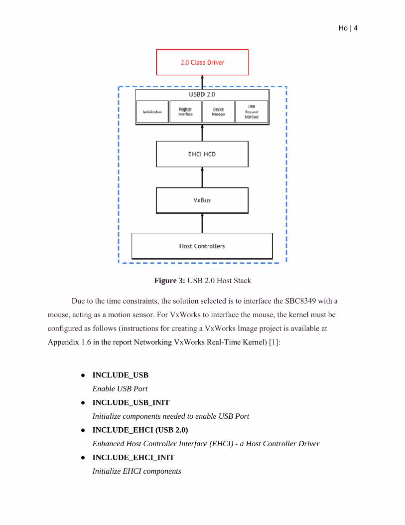
Displayed in Figure 3, is the overview of the VxWorks operating system’s USB 2.0 host
stack. To interface a device with VxWorks operating system, one requires a correct host
controller driver, and a class driver to enable the device’s functions, and to register the device to
the USBD (USB Host Driver) interface. VxWorks has limited available pool of class drivers for
USB devices. To interface a sensor to VxWorks operating system a class generation 2.0 driver
would need to be developed.
Ho | 4
Figure 3: USB 2.0 Host Stack
Due to the time constraints, the solution selected is to interface the SBC8349 with a
mouse, acting as a motion sensor. For VxWorks to interface the mouse, the kernel must be
configured as follows (instructions for creating a VxWorks Image project is available at
Appendix 1.6 in the report Networking VxWorks Real-Time Kernel) [1]:
● INCLUDE_USB
Enable USB Port
● INCLUDE_USB_INIT
Initialize components needed to enable USB Port
● INCLUDE_EHCI (USB 2.0)
Enhanced Host Controller Interface (EHCI) - a Host Controller Driver
● INCLUDE_EHCI_INIT
Initialize EHCI components

Ho | 5
● INCLUDE_HCD_BUS
Register Host Control Driver with VxBus
● INCLUDE_USB_MOUSE
Driver for Mass Storage Device
● INCLUDE_USB_MOUSE_INIT
Initializer of Mass Storage Device Driver
A3.2 Data Logger
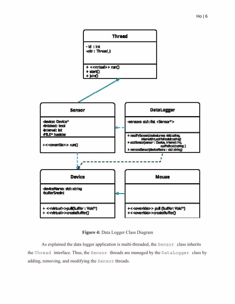
The datalogger design for VxWorks will pull data from the interfaced sensors and write
the data to a designated location. Each physical sensor added on to the data logger will have a
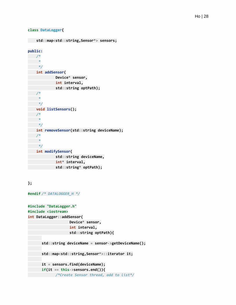
designated FILE pointer where the data will be placed. As shown in Figure 4, the class
DataLogger has a Device class dependency in the DataLogger::addSensor()
function. The function will require a path for the pulled data to be written to, and an interval
variable for designating the delay between each function call for pulling data from a sensor. For
instance, when the interval variable is set to zero, the sensor threads will pull and write data as
fast as possible.
Moreover, the DataLogger class will manage a list of sensor threads. This design will
prevent the main thread from being blocked, since all the data polling and processing will be
done on the Sensor threads. Even though VxWorks is not fully POSIX compliant, VxWorks
support the usage of the Pthreads library. Due to the familiarity of Pthreads API, the data logger
application is designed with Pthreads, and not with the standard VxWorks Threads API.
Ho | 6
Figure 4: Data Logger Class Diagram
As explained the data logger application is multi-threaded, the Sensor class inherits
the Thread interface. Thus, the Sensor threads are managed by the DataLogger class by
adding, removing, and modifying the Sensor threads.
Ho | 7
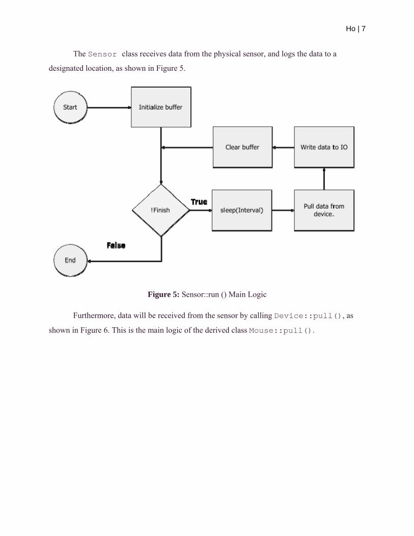
The Sensor class receives data from the physical sensor, and logs the data to a
designated location, as shown in Figure 5.
Figure 5: Sensor::run () Main Logic
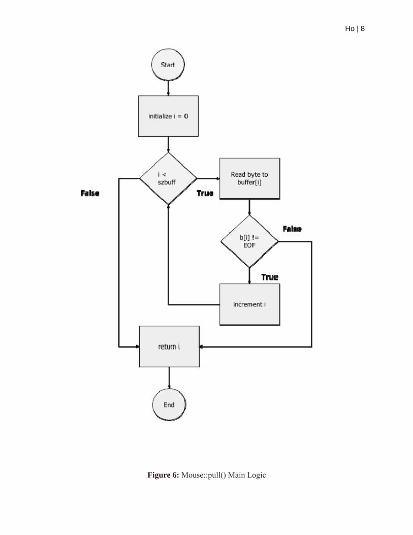
Furthermore, data will be received from the sensor by calling Device::pull(), as
shown in Figure 6. This is the main logic of the derived class Mouse::pull().
Ho | 8
Figure 6: Mouse::pull() Main Logic
Ho | 9
Following the main logic of the designs, the code implementation of both the function is
displayed below.
Figure 7, displays the implementation of Mouse::pull(). As shown by the function,
the code is customized specifically for a mouse device. For instance, a mouse’s first three bytes
displays: byte one bit flags representing button input, byte two delta x coordinate, byte three
delta y coordinate. With the above statement in mind, the Mouse::pull() reads the first
three bytes, storing the received values into the function’s parameter called buffer, for which the
caller of Mouse::pull() will further process the data.
Figure 7: Mouse::pull() Code
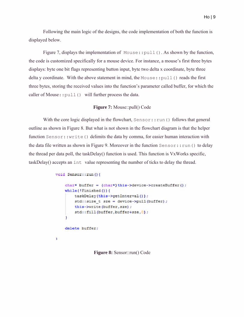
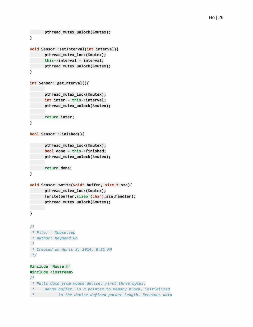
With the core logic displayed in the flowchart, Sensor::run() follows that general
outline as shown in Figure 8. But what is not shown in the flowchart diagram is that the helper
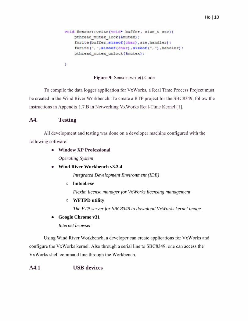
function Sensor::write() delimits the data by comma, for easier human interaction with
the data file written as shown in Figure 9. Moreover in the function Sensor::run() to delay
the thread per data poll, the taskDelay() function is used. This function is VxWorks specific,
taskDelay() accepts an int value representing the number of ticks to delay the thread.
Figure 8: Sensor::run() Code
Ho | 10
Figure 9: Sensor::write() Code
To compile the data logger application for VxWorks, a Real Time Process Project must
be created in the Wind River Workbench. To create a RTP project for the SBC8349, follow the
instructions in Appendix 1.7.B in Networking VxWorks Real-Time Kernel [1].
A4. Testing
All development and testing was done on a developer machine configured with the
following software:
● Window XP Professional
Operating System
● Wind River Workbench v3.3.4
Integrated Development Environment (IDE)
○ lmtool.exe
Flexlm license manager for VxWorks licensing management
○ WFTPD utility
The FTP server for SBC8349 to download VxWorks kernel image
● Google Chrome v31
Internet browser
Using Wind River Workbench, a developer can create applications for VxWorks and
configure the VxWorks kernel. Also through a serial line to SBC8349, one can access the
VxWorks shell command line through the Workbench.
A4.1 USB devices

Ho | 11
To diagnose a USB device, or to help develop a USB class driver, the following
diagnostic commands are available:
● usbTool
USB exerciser, version 02A
● usbShow
List USB ports with descriptor dumps
The usbTool is a USB code exerciser. For instance, when developing a new USB driver
one would use the usbTool to help debug and exercise the driver code. Besides developing
drivers, usbTool can be used to diagnose for faulty hardware, as in testing USB devices with the
predefined device test commands. To enable the usbTool command for VxWorks kernel, one
would need to build the VxWorks kernel as follows:
● INCLUDE_USBTOOL
Enable the USB exerciser
● EXCLUDE ALL INCLUDE_XXX_INIT
Remove all USB related initialization
With the VxWorks kernel configured correctly for usbTool, one would start the utility by
typing in the VxWorks shell command line, “usbTool” as shown in Figure 10.
Figure 10: usbTool
Once, the usbTool is initialized, there are commands available to test out VxWorks USB
host stack. To test a mouse device using usbTool, one would input the following commands:
Ho | 12
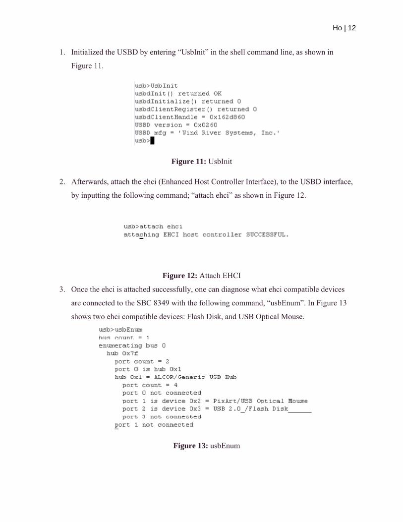
1. Initialized the USBD by entering “UsbInit” in the shell command line, as shown in
Figure 11.
Figure 11: UsbInit
2. Afterwards, attach the ehci (Enhanced Host Controller Interface), to the USBD interface,
by inputting the following command; “attach ehci” as shown in Figure 12.
Figure 12: Attach EHCI
3. Once the ehci is attached successfully, one can diagnose what ehci compatible devices
are connected to the SBC 8349 with the following command, “usbEnum”. In Figure 13
shows two ehci compatible devices: Flash Disk, and USB Optical Mouse.
Figure 13: usbEnum
Ho | 13
4. Lastly with a USB device recognized by VxWorks kernel, for devices that already have
USB class drivers; keyboard, mouse, speaker, printer, etc, one can activate a provided
device test command.
a. To active a device’s test command, the devices driver components must be
included in the kernel configuration (All related USB initialization must still be
excluded).
b. With the Mouse device driver components included, and with steps 1 to 3
finished, the test command “mouseTest” is available. To activate it, be in
usbTool’s command line and type “mouseTest”, for which one can verify the
mouse's button states, and x and y coordinates.
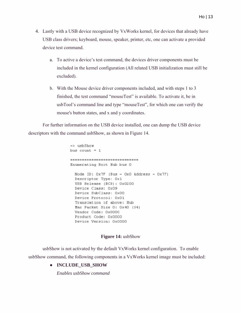
For further information on the USB device installed, one can dump the USB device
descriptors with the command usbShow, as shown in Figure 14.
Figure 14: usbShow
usbShow is not activated by the default VxWorks kernel configuration. To enable
usbShow command, the following components in a VxWorks kernel image must be included:
● INCLUDE_USB_SHOW
Enables usbShow command
Ho | 14
With the tool usbShow available one can develop a USB device class driver. An example
of creating a Wind River USB class driver is available in section 7.2 in Wind River USB
Programmers Guide 3.0 [2].
A4.2 Data Logger
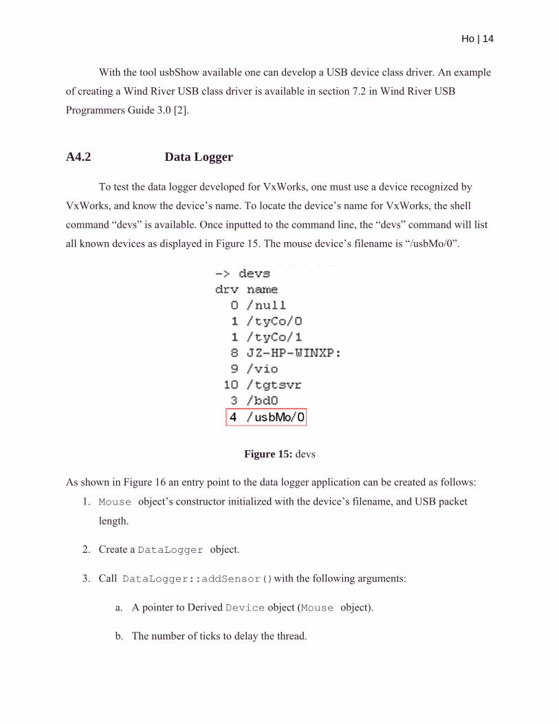
To test the data logger developed for VxWorks, one must use a device recognized by
VxWorks, and know the device’s name. To locate the device’s name for VxWorks, the shell
command “devs” is available. Once inputted to the command line, the “devs” command will list
all known devices as displayed in Figure 15. The mouse device’s filename is “/usbMo/0”.
Figure 15: devs
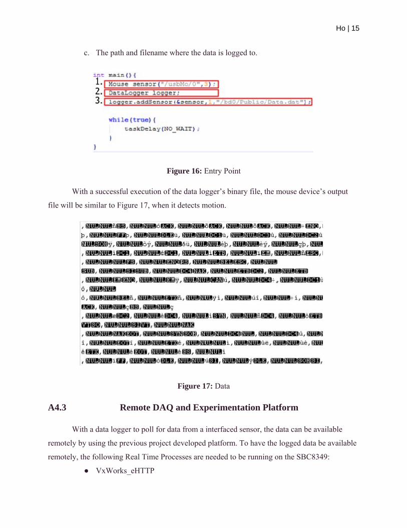
As shown in Figure 16 an entry point to the data logger application can be created as follows:
1. Mouse object’s constructor initialized with the device’s filename, and USB packet
length.
2. Create a DataLogger object.
3. Call DataLogger::addSensor()with the following arguments:
a. A pointer to Derived Device object (Mouse object).
b. The number of ticks to delay the thread.
Ho | 15
c. The path and filename where the data is logged to.
Figure 16: Entry Point
With a successful execution of the data logger’s binary file, the mouse device’s output
file will be similar to Figure 17, when it detects motion.
Figure 17: Data
A4.3 Remote DAQ and Experimentation Platform
With a data logger to poll for data from a interfaced sensor, the data can be available
remotely by using the previous project developed platform. To have the logged data be available
remotely, the following Real Time Processes are needed to be running on the SBC8349:
● VxWorks_eHTTP

Ho | 16
HTTP server, directory pointed to that flash drive
● DataLogger_VxWorks
Data logger application outputting to the flash drive
To test the two processes cohesion, both of the applications will need to point to the same
directory tree and running. To execute both of the RTP processes, a user would use the “rtp
exec” command available in VxWorks Command Interpreter Shell. To enter VxWorks
Command Interpreter Shell and execute the data logger application and eHTTP server is as
follows:
1. From the Wind River Workbench access the target terminal, by default the command
shell is in C-Interpreter mode. To change to Command Interpreter mode, a user would
type in the command “cmd”.
2. Once in the Command Interpreter Shell, a user will need to input the commands as
displayed in Figure 18 and 19.
Figure 18: Executing eHTTP
Figure 19: Executing Data Logger
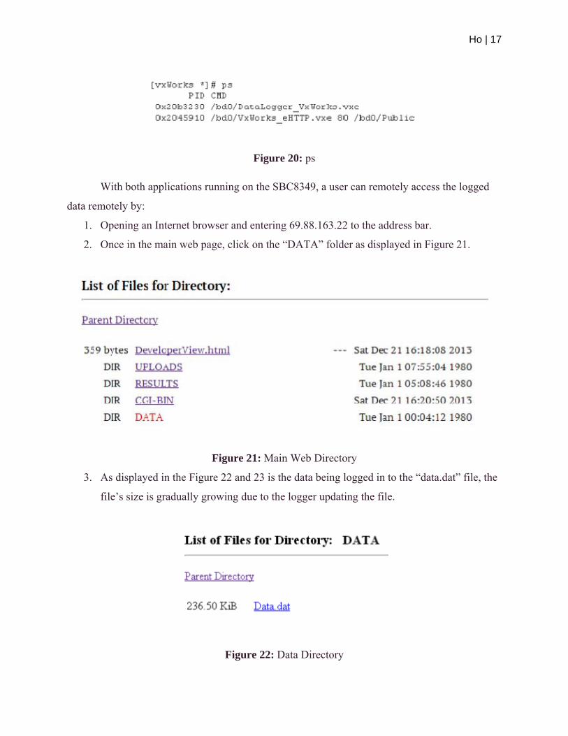
3. To display the user processes after successful execution, enter the command “ps” into the
Command Interpreter Shell, the output will be as shown in Figure 20.
Ho | 17
Figure 20: ps
With both applications running on the SBC8349, a user can remotely access the logged
data remotely by:
1. Opening an Internet browser and entering 69.88.163.22 to the address bar.
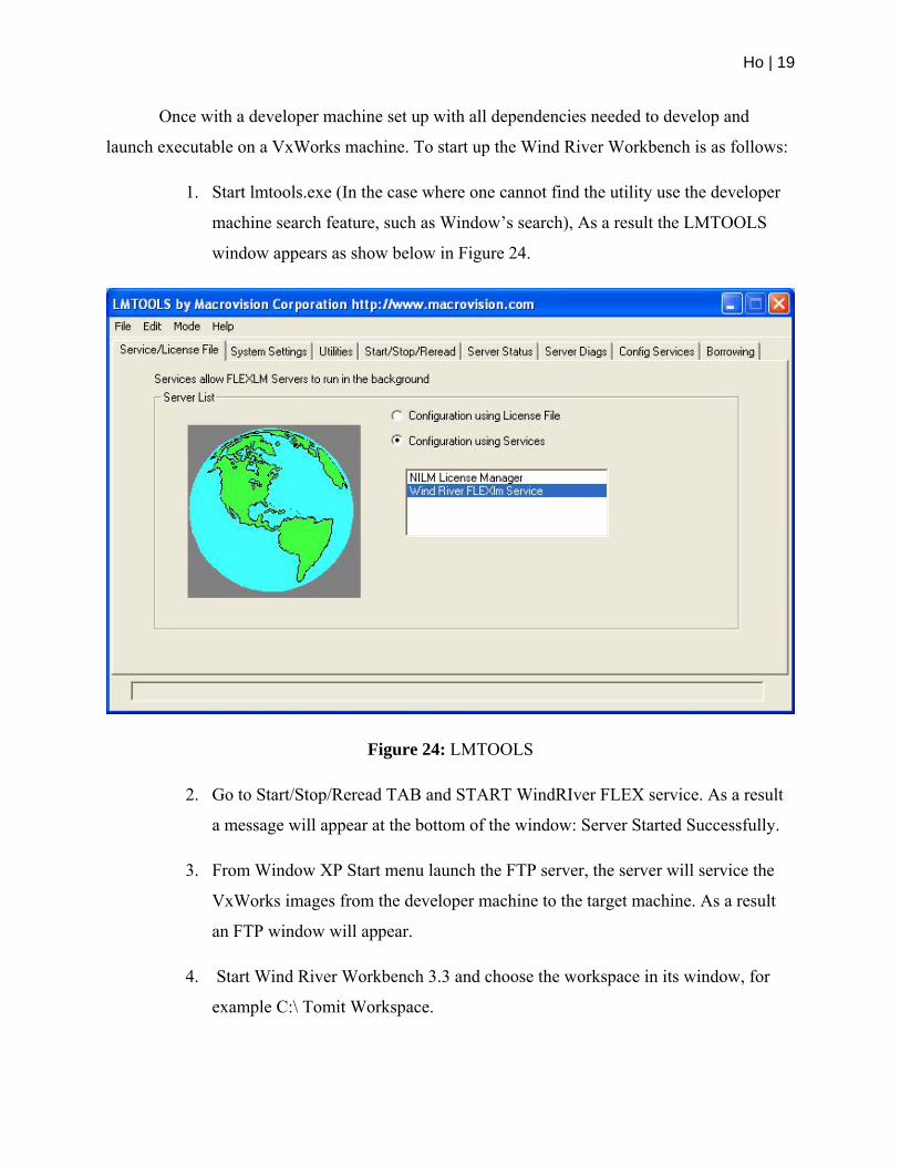
2. Once in the main web page, click on the “DATA” folder as displayed in Figure 21.
Figure 21: Main Web Directory
3. As displayed in the Figure 22 and 23 is the data being logged in to the “data.dat” file, the
file’s size is gradually growing due to the logger updating the file.
Figure 22: Data Directory

Ho | 18
Figure 23: Refreshed Data Directory
A5. Conclusion
The maintenance project’s goal for VxWorks is to have a sensor interface with the
SBC8349 running VxWorks, and to develop a data logger software for the sensor. Both was
accomplished, but the current sensor used for the SBC8349 is rudimentary. Furthermore a issue
arises when working with multiple USB devices, the devices connected through the USB hub
when used simultaneously will periodically deactivate. The theory to the issue is that the
SBC8349 does not provide enough power to simultaneously run multiple devices when splitting
the USB host port. To solve this issue one would need to acquire a USB hub that is supported by
an external power supply, for instance Plugable USB2-HUB10S. This device can be bought from
Amazon or any other online retailers, http://www.amazon.com/Plugable-USB-Port-Power-
Adapter/dp/B00483WRZ6
With the issue resolved to further the project, one could interface the SBC8349 with a
more advance sensor by developing a class 2.0 USB driver.
A6. References
[1] Nguyen, Ho, Networking VxWorks Real-Time Kernel,
Florida Gulf Coast University, Fort Myers, FL., October 2013.
[2] Wind River Inc., Wind River USB Programmer’s Guide 3.0,
Wind River, Alameda, CA., October 2012.
Amendment 1 Setting up Wind River Workbench
Ho | 19
Once with a developer machine set up with all dependencies needed to develop and
launch executable on a VxWorks machine. To start up the Wind River Workbench is as follows:
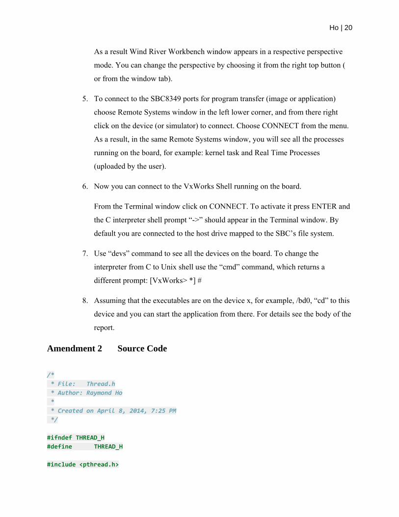
1. Start lmtools.exe (In the case where one cannot find the utility use the developer
machine search feature, such as Window’s search), As a result the LMTOOLS
window appears as show below in Figure 24.
Figure 24: LMTOOLS
2. Go to Start/Stop/Reread TAB and START WindRIver FLEX service. As a result
a message will appear at the bottom of the window: Server Started Successfully.
3. From Window XP Start menu launch the FTP server, the server will service the
VxWorks images from the developer machine to the target machine. As a result
an FTP window will appear.
4. Start Wind River Workbench 3.3 and choose the workspace in its window, for
example C:\ Tomit Workspace.
Ho | 20
As a result Wind River Workbench window appears in a respective perspective
mode. You can change the perspective by choosing it from the right top button (
or from the window tab).
5. To connect to the SBC8349 ports for program transfer (image or application)
choose Remote Systems window in the left lower corner, and from there right
click on the device (or simulator) to connect. Choose CONNECT from the menu.
As a result, in the same Remote Systems window, you will see all the processes
running on the board, for example: kernel task and Real Time Processes
(uploaded by the user).
6. Now you can connect to the VxWorks Shell running on the board.
From the Terminal window click on CONNECT. To activate it press ENTER and
the C interpreter shell prompt “->” should appear in the Terminal window. By
default you are connected to the host drive mapped to the SBC’s file system.
7. Use “devs” command to see all the devices on the board. To change the
interpreter from C to Unix shell use the “cmd” command, which returns a
different prompt: [VxWorks> *] #
8. Assuming that the executables are on the device x, for example, /bd0, “cd” to this
device and you can start the application from there. For details see the body of the
report.
Amendment 2 Source Code
/*
* File: Thread.h
* Author: Raymond Ho
*
* Created on April 8, 2014, 7:25 PM
*/
#ifndef THREAD_H
#define THREAD_H
#include <pthread.h>

Ho | 21
/*Thread interface*/
class Thread{
pthread_t id;
pthread_attr_t* attr;
pthread_mutex_t suspendMutex;
pthread_cond_t resumeCond;
bool isSuspended;
public:
Thread():id(0),
attr(NULL),
isSuspended(false){
pthread_mutex_init(&suspendMutex,NULL);
pthread_cond_init(&resumeCond,NULL);
}
virtual ~Thread(){
if(attr){
delete attr;
attr = NULL;
}
pthread_mutex_destroy(&suspendMutex);
pthread_cond_destroy(&resumeCond);
}
virtual void run() = 0;
int start(){
return pthread_create(&id,attr,functionRouter,this);
}
int join(void * Result = NULL){
return pthread_join(id,&Result);
}
pthread_t getThreadID(){
return this‐>id;
}

Ho | 22
void suspend(){
pthread_mutex_lock(&suspendMutex);
isSuspended= true;
do{
pthread_cond_wait(&resumeCond,&suspendMutex);
}while(isSuspended);
pthread_mutex_unlock(&suspendMutex);
}
void resume(){
pthread_mutex_lock(&suspendMutex);
isSuspended = false;
pthread_cond_signal(&resumeCond);
pthread_mutex_unlock(&suspendMutex);
}
private:
static void* functionRouter(void *This){
((Thread*)This)‐>run();
return NULL;
}
};
#endif /* THREAD_H */
#ifndef DEVICE_H
#define DEVICE_H
#include <stdio.h>
#include <string>
class Device {
protected:
FILE* handler;
size_t bufferSze;
std::string deviceName;
public:
Device(
std::string deviceName,
size_t Sze)
: bufferSze(Sze),

Ho | 23
deviceName(deviceName){
handler = fopen(deviceName.c_str(),"w+");
}
virtual size_t pull(void* buffer)=0;
virtual void * createBuffer()=0;
virtual std::string getDeviceName()=0;
virtual ~Device(){
if(handler)
fclose(handler);
}
};
#endif
/*
* File: Mouse.h
* Author: Raymond Ho
*
* Created on April 8, 2014, 8:09 PM
*/
#ifndef MOUSE_H
#define MOUSE_H
#include "Device.h"
class Mouse: public Device{
public:
Mouse(std::string deviceName,int sze)
:Device(deviceName,sze){}
std::size_t pull(void* buffer);
void * createBuffer();
std::string getDeviceName();
~Mouse(){
Ho | 24
}
};
#endif /* MOUSE_H */
/*
* File: Sensor.h
* Author: Raymond Ho
*
* Created on April 9, 2014, 2:31 PM
*/
#ifndef SENSOR_H
#define SENSOR_H
#include "Device.h"
#include "Thread.h"
#include <string.h>
#include <iolib.h>
class Sensor: public Thread {
bool finished;
int interval;
FILE * handler;//Output
Device * device;
pthread_mutex_t mutex;
public:
Sensor(
Device * device,
int interval,
std::string optPath)
:finished(false),
device(device),
interval(interval),
handler(NULL){
pthread_mutex_init(&mutex,NULL);
handler = fopen(optPath.c_str(), "a+");
}
void run();
void end();
void setOptLocation(std::string optPath);

Ho | 25
void setInterval(int interval);
int getInterval();
~Sensor(){
pthread_mutex_destroy(&mutex);
}
private:
bool Finished();
void write(void* buffer, size_t sze);
};
#endif /* SENSOR_H */
#include "Sensor.h"
#include <unistd.h>
#include <iostream>
#include <taskLibCommon.h>
void Sensor::run(){
char* buffer = (char*)this‐>device‐>createBuffer();
while(!Finished()){
taskDelay(this‐>getInterval());
std::size_t sze = device‐>pull(buffer);
this‐>write(buffer,sze);
std::fill(buffer,buffer+sze,0);
}
delete buffer;
}
void Sensor::end(){
this‐>finished = true;
}
void Sensor::setOptLocation(std::string optPath){
pthread_mutex_lock(&mutex);
if(handler){
fclose(handler);
}
handler = fopen(optPath.c_str(),"a+");
Ho | 26
pthread_mutex_unlock(&mutex);
}
void Sensor::setInterval(int interval){
pthread_mutex_lock(&mutex);
this‐>interval = interval;
pthread_mutex_unlock(&mutex);
}
int Sensor::getInterval(){
pthread_mutex_lock(&mutex);
int inter = this‐>interval;
pthread_mutex_unlock(&mutex);
return inter;
}
bool Sensor::Finished(){
pthread_mutex_lock(&mutex);
bool done = this‐>finished;
pthread_mutex_unlock(&mutex);
return done;
}
void Sensor::write(void* buffer, size_t sze){
pthread_mutex_lock(&mutex);
fwrite(buffer,sizeof(char),sze,handler);
pthread_mutex_unlock(&mutex);
}
/*
* File: Mouse.cpp
* Author: Raymond Ho
*
* Created on April 8, 2014, 8:51 PM
*/
#include "Mouse.h"
#include <iostream>
/*
* Pulls data from mouse device, first three bytes.
* param buffer, is a pointer to memory block, initialized
* to the device defined packet length. Receives data

Ho | 27
* from the device.
*/
std::size_t Mouse::pull(void* buffer){
char * b = (char*)buffer;
int i = 0;
while(i < this‐>bufferSze){
int c = getc(this‐>handler);
if(c == EOF) break;
b[i] = c;
i++;
}
return i;
}
void* Mouse::createBuffer(){
return (void*)new char[this‐>bufferSze];
}
std::string Mouse::getDeviceName(){
return this‐>deviceName;
}
/*
* File: DataLogger.h
* Author: Raymond Ho
*
* Created on April 8, 2014, 5:03 PM
*/
#ifndef DATALOGGER_H
#define DATALOGGER_H
#include <list>
#include "Thread.h"
#include "device.h"
#include "Sensor.h"
#include <map>
Ho | 28
class DataLogger{
std::map<std::string,Sensor*> sensors;
public:
/*
*
*/
int addSensor(
Device* sensor,
int interval,
std::string optPath);
/*
*
*/
void listSensors();
/*
*
*/
int removeSensor(std::string deviceName);
/*
*
*/
int modifySensor(
std::string deviceName,
int* interval,
std::string* optPath);
};
#endif /* DATALOGGER_H */
#include "DataLogger.h"
#include <iostream>
int DataLogger::addSensor(
Device* sensor,
int interval,
std::string optPath){
std::string deviceName = sensor‐>getDeviceName();
std::map<std::string,Sensor*>::iterator it;
it = sensors.find(deviceName);
if(it == this‐>sensors.end()){
/*Create Sensor thread, add to list*/

Ho | 29
Sensor* device = new Sensor(
sensor,
interval,
optPath);
device‐>start();
sensors[deviceName] = device;
/*Success*/
return 0;
}
/*
* There is already a sensor,
* using the same physical device
*/
return ‐1;
}
int DataLogger::removeSensor(std::string deviceName){
std::map<std::string,Sensor*>::iterator it;
it = sensors.find(deviceName);
if(it != sensors.end()){
Sensor* sensor = it‐>second;
sensor‐>end();
/*Wait till thread ends*/
sensor‐>join();
/*Success*/
return 0;
}
/*
* No thread found to remove
*
*/
return ‐1;
}
int DataLogger::modifySensor(
std::string deviceName,//search for
int* interval,
std::string* optPath){
std::map<std::string,Sensor*>::iterator it;

Ho | 30
it = sensors.find(deviceName);
if(it != sensors.end()){
Sensor* sensor = it‐>second;
if(interval){
sensor‐>setInterval(*interval);
}
if(optPath){
sensor‐>setOptLocation(*optPath);
}
/*Success*/
return 0;
}
return ‐1;
}
#include "Sensor.h"
#include "Mouse.h"
#include "DataLogger.h"
#include <iostream>
#include <taskLibCommon.h>
#include <sysLib.h>
int main(){
Mouse sensor("/usbMo/0",3);
DataLogger logger;
logger.addSensor(&sensor,1,"/bd0/Public/Data.dat");
while(true){
taskDelay(NO_WAIT);
}
}


