
ii
ANALYSIS OF DIESEL SPRAY CHARACTERISTIC USING SINGLE HOLE
SAC NOZZLE AND VCO NOZZLE
MOHD FAZWAN BIN ISHAK
Report submitted in partial fulfillment of the requirements
for the award of Bachelor of Mechanical with Automotive Engineering
Faculty of Mechanical Engineering
UNIVERSITI MALAYSIA PAHANG
JUNE 2012

vi
ABSTRACT
This study was focus to investigate the diesel spray characteristics and atomization performance. The influences of injector nozzle geometry and injection pressure conditions on a diesel fuel spray were examined and predicted by using ANSYS FLUENT software. A flow domain and constant volume combustion chamber was designed and temperature was set 540 K at pressure 1 MPa for simulations. Spray penetration length and cone angle of diesel spray were recorded. To investigate the influence of nozzle geometry, Sac and VCO (Valve Covers Orifice) with difference diameter orifice and injection pressure were designed and used in both spray evolution. Comparisons were made between different nozzle geometries and different injection pressures. Differences were observed between VCO and Sac nozzles, with the Sac nozzles showing a higher rate of penetration under the same conditions.

vii
ABSTRAK
Kajian ini adalah fokus untuk mengetahui sifat-sifat semburan diesel dan prestasi pengatoman. Pengaruh rupa bentuk muncung dan keadaan tekanan penyuntikan dalam bahan bakar diesel diuji dan diramal menggunakan perisian ANSYS FLUENT 12.1. Kawasan aliran dan isipadu kebuk yang tetap telah direkabentuk dan ditetapkan suhu 540 K pada tekanan 1MPa untuk simulasi. Panjang penembusan semburan dan sudut kon semburan diesel telah dicatat. Untuk mengkaji pengaruh rupa bentuk muncung, Sac dan VCO (Valve Covers Orifice) dengan berbeza diameter lubang dan tekanan suntikan telah direkabentuk dan digunakan untuk kedua-dua kembangan semburan. Perbandingan telah dibuat antara reka bentuk muncung yang berbeza dan berbeza tekanan suntikan. Perbezaan telah diperhatikan antara muncung VCO dan Sac, dengan muncung Sac menunjukan kadar penembusan yang tinggi di bawah keadaan yang sama.

viii
TABLE OF CONTENTS
Page
PANEL DECLARATION ii
SUPERVISOR’S DECLARATION iii
STUDENT’S DECLARATION iv
ACKNOWLEDGEMEN v
ABSTRACT vi
ABSTRAK vii
TABLE OF CONTENTS viii
LIST OF FIGURES x
LIST OF SYMBLOS xii
LIST OF ABBREVIATIONS xiii
LIST OF APPENDICES xiv
CHAPTER 1 INTRODUCTION 1
1.1 Project Background 1
1.2 Problem Statement 2
1.3 Objectives 2
1.4 Work scopes 2
1.5 Flow Chart 3
CHAPTER 2 LITERATURE REVIEW 5
2.1 Operation Of Diesel Engine 5
2.2 Atomization 7
2.3 Diesel Spray Characteristics 9
2.4 Spray Parameters 11
2.5 Formation of Liquid Spray 12
2.6 Computational Fluid Dynamics (CFD) 13
2.7 Examples of CFD 14

ix
2.7.1 Using Star-CD 14 2.7.2 Using KIVA-3D 16 2.7.3 Using FLUENT 17 2.7.4 Using AVL 18
2.8 Advantages of CFD 20
CHAPTER 3 METHODOLOGY 21
3.1 ANSYS Workbench 21
3.2 Modeling The Flow Domain & Geometry 22
3.3 Meshing 24
3.4 Setup 25
3.4.1 Turbulence Models 26 3.4.2 Boundary Condition 27
3.5 Solution 27
3.6 Results 28
CHAPTER 4 RESULTS AND DISCUSSION 29
4.1 Influent of Injection Pressure 30
4.2 Influent of Nozzle Geometry 32
4.3 Comparison Cone Angle between Two Difference Geometry 34
CHAPTER 5 CONCLUSION 35
5.1 Conclusion 35
5.2 Recommendation and Future Work 36
REFERENCES 37
APPENDICES 39

x
LIST OF FIGURES
Figure No. Page 1.1 Flow chart of methodology 4 2.1 Diesel combustion system 6 2.2 Spray regimes 8 2.3 Variable of injection process 9 2.4 Spray Parameters 12 2.5 Flow pattern of a spray formation near the nozzle tip region 13 2.6a Computational domain 14 2.6b Numerical result 15 2.7a Computational domain 16 2.7b Numerical result 17 2.8 Computational domain and Numerical result 18 2.9a Computational domain 19 2.9b Numerical result 19 3.1 ANSYS Workbench 22 3.2 Geometry domain for high pressure chamber (3D) 23 3.3 Flow Domain in Sac nozzle through the high pressure 23 chamber 3.4 The mesh showing at enlarged orifice region 24 3.5 Named Selection of flow model 25 3.6 Boundary condition 27 3.7 Simulation result 28
4.1 Comparison of result for difference injection pressure 30

xi
4.2 Comparison of experimental penetration rate for varying 31 injection pressures (VCO, 0.2mm) 4.3 Comparison of result penetration rate for difference nozzle 33 sizes and types 4.4 Comparison cone angle between Sac and VCO with same 34 parameters

xii
LIST OF SYMBOLS
ρl Pressure of liquid injected fluid
ρg Pressure of gas working fluid
μ∗ Relation of viscosities length
μl Kinematic viscosity orifice entrance curvature
μg Kinematic viscosity
v Velocity
σ True stress
d Orifice diameter
𝑙𝑙 Length
∆𝑃𝑃 Pressure increasing
xiii
LIST OF ABBREVIATIONS
VCO Valve Covers Orifice CFD Computational fluid dynamics SMD Sauter Mean Diameter IQT Ignition Quality Tester CAD Computer-aided design DNS Direct Numerical Simulations RNG Renormalization-group Re Reynolds Number We Weber Number Ta Taylor Viscosity Parameter Oh Ohnesorge Number
xiv
LIST OF APPENDICES
Page
GANTT CHART FOR FYP 1 39 GANTT CHART FOR FYP 2 40 DIMENSION OF SAC NOZZLE 41
DIMENSION OF VCO NOZZLE 42

1
CHAPTER 1
INTRODUCTION
1.1 PROJECT BACKGROUND
Diesel engines are widely used because of their high efficiency and cost
effectiveness. Recently, passenger cars have adopted such engines, due to their
inherent advantages over gasoline counterparts. Diesel engines have been the
favorite power train for heavy-duty vehicles and non-road applications, and their use
in light duty vehicles has been increasing. But, diesel engine designers are
challenged by the need to fulfill with ever more stringent emissions standards while
at the same time improving engine efficiency. Increasingly stringent emissions
regulations as well as fuel economy demands means that diesel engines will have to
incorporate new fueling technologies to achieve these goals. In order to increase
engine efficiency and reduce emissions, great attention has been focused on
improving fuel atomization.
The aim of this project was to study the effect of nozzle geometry against the
fuel spray behavior. Comparisons were made between different nozzle geometries
and different injection pressures. Differences were observed between VCO (Valve
Covers Orifice) and Sac nozzles. The physical properties of diesel such as density,
viscosity, and surface tension were stated and used in the numerical simulations.
Injection process parameters such as injection pressure, nozzle needle lift, injection
rate, and volume of injected fuel were controlled on the fuel injection systems in
simulation setup.
2
1.2 PROBLEM STATEMENT
Diesel sprays have been studied for more than a century but were still under
research. Through studies by different researchers, it was found spray evaporation
and mixture formation during ignition delay period play an important role in ignition,
combustion and emission production in diesel engine. Spray evaporation begins
immediately after fuel emerged from nozzle. Therefore, the nozzle geometry plays an
important role in fuel spray behavior inside spray chamber. In this study, the effect
various nozzle geometry such as sac nozzle and VCO nozzle will be investigated.
1.3 OBJECTIVES
i. To study the effect of diesel spray characteristic using difference injector
nozzle geometry in diesel engine.
ii. To investigate the influences of diesel spray characteristic using difference
injection pressure in diesel engine.
1.4 WORK SCOPES
i. The project was conducted using ANSYS FLUENT 12.1 software on
focusing measuring the spray penetration length and spray cone angle.
ii. Two difference type of nozzle which is Sac and Valve Covers Orifice
(VCO) was used and the simulation result from these type nozzle was
compared.
iii. All the information parameters used taken from previous experimental
research.

3
1.5 FLOW CHART
The project starts with literature review and research about title such as a
review of concept of atomization and process, design of chamber and nozzle
geometry, injection characteristics, software used, and sprays modeling. These tasks
have been done through research on the books, journals, technical reports and other
sources.
After gathering all relevant information, the project undergoes to spray
model. From the knowledge gathered, the review was used to design the injector,
chamber and other to complete the system spray. After completing the spray model,
the simulation was run. All results were recorded. When something error or problems
arose in this step, the spray model was modified.
The next step was analysis result. Result from simulation was observed and
made comparisons between two geometry nozzles. The comparisons were include
the spray angle and spray penetration length between Sac and VCO nozzles using
difference parameters.
The report was process after complete the analysis. All information like
figures, tables and any references were collected to complete the report. Report had
been guided by the UMP thesis report writing. This process also included the
presentation slide marking for the final presentation of the project. The project ended
after the submission of the report. All the procedures and steps for this project was
constructing into the flow chart (refer Figure 1.1).

4
Figure 1.1: Flow chart of methodology.

5
CHAPTER 2
LITERATURE REVIEW
In this chapter all information related for this project was presented. This
chapter will explain in detail about operation of diesel engine, atomization, spray
parameters, formation of liquid spray, Computational Fluid Dynamics (CFD) and
examples of CFD. Using CFD has a lot of benefit, save money and easy to conduct.
At the end of this chapter will explain about advantages of using CFD in this project.
2.1 OPERATION OF DIESEL ENGINE
Figure 2.1 shows the diagram of diesel engine operation system. In a diesel
engine, also known as a compression-ignited engine, air enters the cylinder through
the intake system. This air was compressed to a high temperature and pressure and
then finely atomized fuel is sprayed into the air at high velocity. When it contacts the
high temperature air, the fuel vaporizes quickly, mixes with the air, and undergoes a
series of spontaneous chemical reactions that result in a self-ignition or autoignition.
No spark plug is required, although some diesel engines are equipped with
electrically heated glow plugs to assist with starting the engine under cold conditions.
The power of the engine is controlled by varying the volume of fuel injected into the
cylinder, so there is no need for a throttle.
The timing of the combustion process must be precisely controlled to provide
low emissions with optimum fuel efficiency. This timing is determined by the fuel
injection timing plus the short time period between the start of fuel injection and the
autoignition called the ignition delay. When the autoignition occur, the portion of the
fuel that had been prepared for combustion burns very rapidly during a period known

6
Figure 2.1: Diesel combustion system.
Source: Lacoste et al, (2006)

7
as premixed combustion. When the fuel that had been prepared during the ignition
delay is exhausted, the remaining fuel burns at a rate determined by the mixing of the
fuel and air. This period is known as mixing- controlled combustion.
The heterogeneous fuel-air mixture in the cylinder during the diesel
combustion process contributes to the formation of soot particles. These particles are
formed in high temperature regions of the combustion chamber where the air-fuel
ratio is fuel-rich and consists mostly of carbon with small amounts of hydrogen and
inorganic compounds.
2.2 ATOMIZATION
The atomization of liquids is a process of great practical importance in diesel
engine. It also finds application in many branches of industry such as mechanical,
chemical, aerospace, metallurgy, medicine, agriculture and many more. For different
applications, the difference operating conditions have may use in order to manipulate
the spray by changing the operating conditions to satisfy their own demands. From
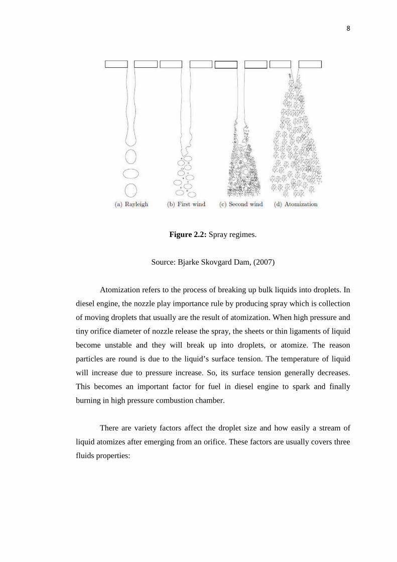
the Figure 2.2, the sprays are usually categorized into four spray regimes:
i. Rayleigh regime: Droplet diameter is larger than jet or spray diameter and
liquid break up occurs at the downstream of the nozzle.
ii. First wind induced regime: Droplet diameter in the order of the spray
diameter. Break up occurs at the downstream of the nozzle.
iii. Second wind induced regime: Droplet diameter smaller is than the
spray diameter and break up starts some distance downstream of nozzle.
iv. Atomization regime: Droplet diameter much smaller than the spray diameter
and break up starts close to the nozzle exit.
8
Figure 2.2: Spray regimes.
Source: Bjarke Skovgard Dam, (2007)
Atomization refers to the process of breaking up bulk liquids into droplets. In
diesel engine, the nozzle play importance rule by producing spray which is collection
of moving droplets that usually are the result of atomization. When high pressure and
tiny orifice diameter of nozzle release the spray, the sheets or thin ligaments of liquid
become unstable and they will break up into droplets, or atomize. The reason
particles are round is due to the liquid’s surface tension. The temperature of liquid
will increase due to pressure increase. So, its surface tension generally decreases.
This becomes an important factor for fuel in diesel engine to spark and finally
burning in high pressure combustion chamber.
There are variety factors affect the droplet size and how easily a stream of
liquid atomizes after emerging from an orifice. These factors are usually covers three
fluids properties:

9
i. Surface tension: It tends to stabilize a fluid, preventing its breakup into
smaller droplets. Everything else being equal, fluids with higher surface
tensions tend to have a larger average droplet size upon atomization.
ii. Viscosity: A fluid’s viscosity has a similar effect on droplet size as surface
tension. Viscosity causes the fluid to resist agitation, tending to prevent its
breakup and leading to a larger average droplet size.
iii. Density: It will cause a fluid to resist acceleration. Similar to the properties of
both surface tension and viscosity, higher density tends to result in a larger
average droplet size.
2.3 DIESEL SPRAY CHARACTERISTICS
Depending on the mechanism to characterize, diesel spray can be analyzed in
a macroscopic or microscopic point of view. With the purpose of understanding in
detail this process, the various physical parameters involved during the transition of a
pulsed diesel spray will be expressed in this chapter, however it is essential to know
the systems that make possible for an injection process to take place. These are the
injection nozzle, active fluid to inject (liquid), and the working fluid on which the
liquid is injected, as shown in Figure 2.3.
Figure 2.3: Variable of injection process.
Source: Vicente et al, (2010)

10
All these variables can be, can be fitted into a dimensionless form that allows
to have much simpler relations and better defined. The dimensionless variables used
in most cases are:
Relation of densities:
ρ∗ = ρlρg
(2.1)
Relation of viscosities:
μ∗ = μlμg
(2.2)
Reynolds Number, relation between inertial and viscous forces:
Re = ρdvμ
(2.3)
Weber Number, relation between superficial tension force and inertial force:
We = ρdv2
μ (2.4)
Taylor Viscosity Parameter:
Ta = ReWe
= σμv
(2.5)
Ohnesorge Number:
Oh = √WeRe
= μ�ρσd
(2.6)

11
Length/diameter relation of the Nozzle = 𝑙𝑙0𝑑𝑑0
Nozzle radius entrance/diameter relation = 𝑟𝑟0𝑑𝑑0
Discharge coefficient of the nozzle:
𝐶𝐶𝑑𝑑 = 𝑣𝑣𝑙𝑙
�2∆𝑃𝑃𝑃𝑃𝑙𝑙
(2.7)
Cavitations Parameter:
𝐾𝐾 = 2(𝑃𝑃𝑙𝑙−𝑃𝑃𝑣𝑣)𝜌𝜌𝑙𝑙𝑣𝑣2 (2.8)
Reynolds number, density and kinematic viscosity must be particularized for
liquid or gas; furthermore these properties can be evaluated for intermediate
conditions between both fluid film conditions. These parameters can be divided into
two groups:
i. External flow parameters (relation of densities, Weber number, Taylor
parameter), these parameters control the interaction between the liquid spray
and the surrounding atmosphere.
ii. Internal flow parameters (Reynolds number, capitations parameter,
length/diameter relation, nozzle radius entrance/diameter relation, discharge
coefficient): these parameters control the interaction between the liquid and
the nozzle.
2.4 SPRAY PARAMETERS
A number of parameters are defined in order to characterize a spray under
certain conditions (refer Figure 2.4). The red color represents the spray projection
area. Some spray commonly used parameters are:

12
i. Penetration: The penetration length is the distance from the nozzle to the end
of spray.
ii. Spray cone angle: The spray angle is used to define the size of the spray. It is
defined as the quasi steady angle, which is reached after the passing of the
spray head.
iii. Sauter Mean Diameter (SMD): The droplet size in the spray is usually
characterized with its SMD. SMD is proportional to the surface to volume
ratio and has the advantage that even if the droplets are not spheres their
surface to volume fraction is equivalent to a sphere and therefore them heat
up and evaporate in the same way.
Figure 2.4: Spray Parameters.
Source: Metin et al, (2011)
2.5 FORMATION OF LIQUID SPRAY
Spray are known the collection of moving droplets or simply the introduction
of liquid into a gaseous environment through a nozzle such that the liquid, through its
interaction with the surrounding gas and by its own instability and breaks-up into
droplets. The formation of a spray begins with the separating of droplets from the
outer surface of a continuous liquid core extending from the orifice of the injection
Spray width Spray
cone l
Penetration

13
nozzle. From Figure 2.5, during spray formation the liquid core will separate into
two difference condition which is primary break-up and secondary break-up.
Primary break-up Secondary break-up
Figure 2.5: Flow pattern of a spray formation near the nozzle tip region.
Source: Faeth et al, (1995)
The separating of the liquid core into ligaments or large droplets is called
primary break-up, which involves the action of forces internal to the liquid jet. Then,
the liquid will have another process is called secondary break-up. In this process, the
liquid ligaments and large droplets will further break-up into small droplets due to
the interactions between the liquid and ambient gas or droplet collisions. The near
nozzle region, where the volume fraction of the liquid is usually larger than that of
the ambient gas is called the dense spray region. And the last region of spray
formation is dilute spray region, which formation of downstream region where the
volume fraction of the liquid is relatively low.
14
2.6 COMPUTATIONAL FLUID DYMNAMICS (CFD)
Computational fluid dynamics is part of fluid mechanics that uses numerical
method and algorithm to solve and analyze problem that related to fluid flow. This
section describes the definition, the examples of simulation and the advantage of
using computational fluid dynamics.
CFD is a computer-based mathematical modeling tool that incorporates the
solution of the fundamental equations of fluid flow, the Navier-Stokes equations, and
other allied equations. CFD incorporates empirical models for modeling turbulence
based on experimentation, as well as the solution of heat, mass and other transport
and field equations. In order to done the calculations, computers are used to compute
such task by using specific software that allows complex calculation for simulation
of intended flow process. There are three phases to CFD:
i. Pre-processing or creation of a geometry usually done in a CAD tool.
ii. Mesh generation of a suitable computational domain to solve the flow
equations.
iii. Solving with post processing, or visualization of a CFD code’s predictions.
CFD is now a widely accepted and validated engineering tool for industrial
applications. The results of CFD analysis are relevant in conceptual studies of new
design, detailed product development, troubleshooting and redesigning.
2.7 EXAMPLES OF CFD
2.7.1 Using Star-CD CFD
The effect of injection orientation on fuel concentration in diesel engine was
investigating using Star-CD software. A single cylinder four stroke DI diesel engine
with fuel injector having multi-hole nozzle injector is considered for the analysis. 45°
sector is taken for the analysis due to the symmetry of eight-hole injector in the
model. The computational mesh when the piston is at Top Dead Center (TDC) is


