
Analysis and Mitigation of Harmonics
in Wind Turbine Transformers
A Major Qualifying Project by Stephen Cialdea,
Marcus Peart, and Warranyu Walton
Advisor: Prof. Alexander Emanuel

Background
There are many types of
generators used in Wind Turbine
designs.
A very popular wind turbine
generator is the Doubly-Fed
Induction Generator.
It is chosen because of its overall
efficiency and wide operating wind
speed.

Problem Statement and Project
Objectives
Problem:
DFIG back to back converter introduces current
harmonics in the line. These harmonics cause heating in
the transformer connected by way of eddy current
losses and skin effect losses.
Objectives:
- Analyze a DFIG harmonics.
- Design a proof-of-concept single phase active
filter that minimizes current harmonics.

DFIG Modeling
PSPICE was used to analyze current harmonics. Model based on Fuhrlander FL1500 wind turbine.
Results suggests a need for either filtering system or an oversized transformer.

Active Filter Basic Concept
sinusoidal current
non-linear load
non-linear current
correction current
corrected current

Design Objectives
Develop a reduced scale model, single phase active
filter that can be scaled up to higher power ratings.
Significantly reduces 2nd to 13th harmonics.
Operates at a line voltage of 12Vrms
Up to 10A peak correction current

Preliminary Modeling
PSPICE models
Used to verify IGBT switching logic for
generating arbitrary waveforms
Conditions:
A: Target Current > 0
B: Correction Current – Target Current > 0
X1, X4 = A && ~B
X2, X3 = B && ~A

Modeling Continued
Line Voltage
(60Hz)
Arbitrary Target
Current (300Hz)
System Output Matching
Arbitrary Target

Single Phase Active Filter Design
Hardware Allegro ACS714 Hall Effect Sensor
Handles up to 20A
100mV per 1A resolution
International Rectifier IRGB8B60KPBF
Continuous collector current of 19A at 100⁰C
VGE(th) of 4.5V typical
International Rectifier IR2110 High and Low Side Driver
Floating channel design for bootstrap operation
Gate drive supply range 10-20V
STM32VL-Discovery Evaluation Board
24MHz Operation
Easy to integrate peripherals with ST standard peripheral library
Free Atollic C Compiler and IDE.

Active Filter Block Diagram
Non-Linear
Current
Sensor
Correction
Current
Sensor
Line
Voltage
Sensor
Comparator
1.5V
STM32VL-DISCOVERY
EXTERNAL
INTERRUPT
DMA MAIN
PROGRAM ADC
Opto-
coupler
H-BRIDGE CIRCUIT
- IR2110 Half-bridge drivers
- IRGB8B60KPBF IGBTs
- Floating 12V supply and
bootstrap circuit
- Inductor for di/dt limiting
Correction Current
Non-linear
Current
Correction
Current
Line
Voltage
Beginning of Cycle to Correction
Current Sensor
to line
from H-Bridge circuit
from line
to Non-Linear Load
from line

Modeling H-Bridge Circuit Simple Switching
No problems with switching.
VCE for U4
Output Current

Experimental Setup
Large auto-transformer to step down input voltage to
12VAC.
Single phase rectifier as source of non-linear current.
Drawing a peak current of approximately 7A

Non-Linear Waveform

Non-Linear Harmonics
0
0.2
0.4
0.6
0.8
1
1.2
1 2 3 4 5 6 7 8 9 10 11 12 13 14 15 16 17 18 19 20 21
Perc
en
tage
Harmonics

Experimental Results
Actual VCE on U4

Experimental Results (Cont.)
0
0.2
0.4
0.6
0.8
1
1.2
1 2 3 4 5 6 7 8 9 10 11 12
Perc
en
tage
Harmonic
Harmonics
Corrected
Nonlinear

Conclusion
Our single phase active filter performed satisfactorily.
Switching noise from the active filter may be eliminated
via a passive filter.
A more fine tuned inductor would improve performance
and reduce switching noise.
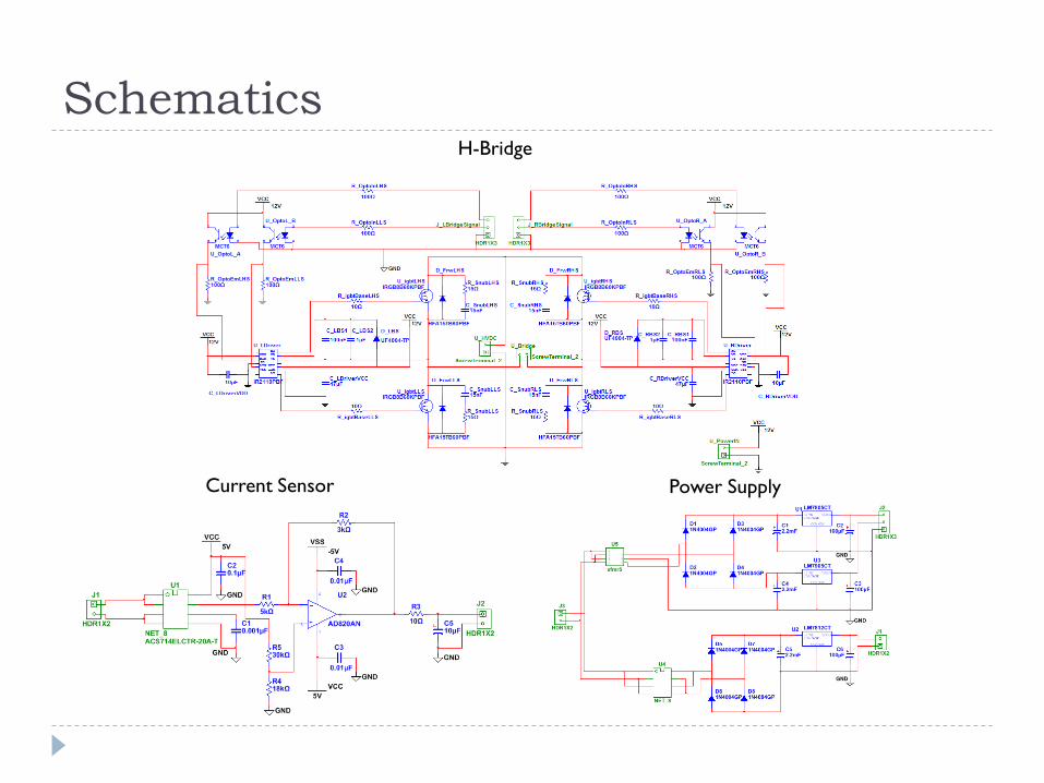
Schematics
Current Sensor Power Supply
H-Bridge

Future Recommendations
Capacitor instead of power supply
3 phase
High power
Additional passive filter to eliminate switching noise

Acknowledgement
Professor Alexander Emanuel
Three-C Electrical Inc.
Princeton Municipal Power and Light
Professor Stephen Bitar


![id-iq Control Strategy for Mitigation of Current Harmonics ...Even though two control strategies [8] with two con-trollers are capable to compensate current harmonics in the 3 phase](https://cdn.vdocuments.us/doc/165x107/5e7115e2334351226771175d/id-iq-control-strategy-for-mitigation-of-current-harmonics-even-though-two-control.jpg)


