
Copyright ⓒ The Korean Society for Aeronautical & Space SciencesReceived: April 8, 2016 Revised: July 1, 2016 Accepted: July 1, 2016
324 http://ijass.org pISSN: 2093-274x eISSN: 2093-2480
PaperInt’l J. of Aeronautical & Space Sci. 17(3), 324–331 (2016)DOI: http://dx.doi.org/10.5139/IJASS.2016.17.3.324
An Experimental Study on the Characteristics of Rectangular Supersonic Jet on a Flat Plate
Ji-Young Kwak*Department of Aerospace and Mechanical Engineering, Graduate School, Korea Aerospace University, Goyang City 10540,
Republic of Korea
Yeol Lee**School of Aerospace and Mechanical Engineering, Korea Aerospace University, Goyang City 10540, Republic of Korea
Abstract
The present study focuses on the characteristics of a supersonic jet flowing from a rectangular nozzle exit on a flat plate. Flow
visualization techniques using schlieren and kerosene-lampblack tracing are utilized to investigate shock reflection structures
and boundary-layer separations over a flat plate. Wall pressure measurements are also carried out to quantitatively analyze
the flow structures. All observations are repeated for multiple jet flow boundary conditions by varying the flap length and
nozzle pressure ratio. The experimental results show that the jet flow structures over the flat plate are highly three-dimensional
with strong bleeding flows from the plate sides, and that they are sensitive to plate length and nozzle pressure ratio. A multi-
component force measurement device is also utilized to observe the characteristics of the jet flow thrust vectoring over the
plate. The maximum thrust deflection angle of the jet is about 8°, demonstrating the applicability of thrust vector control via a
flat plate installed at the nozzle exit.
Key words: supersonic jet, rectangular nozzle, shock wave, flow separation
Nomenclature
H Nozzle exit height, [mm]
L Length of flat plate (or aft-deck), [mm]
M Mach number
NPR Nozzle pressure ratio
s Gap distance between nozzle exit lip and plate
surface, or backward step height [mm]
T Resultant thrust, T=
2
Nomenclature
H Nozzle exit height, [mm]
L Length of flat plate (or aft-deck), [mm]
M Mach number
NPR Nozzle pressure ratio
s Gap distance between nozzle exit lip and plate surface, or backward step height [mm]
T Resultant thrust, � � ���� � ���, [N]
Tz Pitch thrust, [N]
Tx Axial thrust, [N]
δp = resultant pitch thrust-vector angle, tan����� ��� �, [deg]
1. Introduction
Many supersonic engine nozzles have employed non-axisymmetric geometries, including
rectangular nozzles, to alleviate jet noise problems. Asymmetric nozzles have additional advantages
such as easy airframe integration, which offers reduced drag and improved stealth capabilities in
military applications. They are also a favorable choice to achieve thrust vectoring control. In the past
several decades, many studies have been carried out to reveal the fundamental characteristics of
supersonic jets from various rectangular nozzles [1-6]. For instance, in his study regarding the impact
of rectangular nozzle aspect ratios on jet noise, Bridges [1] revealed that rectangular nozzles were
able to reduce jet noise to a great degree than axisymmetric nozzles. Rice [2] also investigated the
influence of nozzle exit geometry on the production of jet noise and mixing characteristics, showing
that a double beveled C-D nozzle were able to reduce peak mixing noises by 4%.
Interactions between supersonic jet flows and flat plate (aft-deck) installed just downstream of the
nozzle exit have drawn increasing attention. Seiner and Manning [7] studied supersonic jet-plate
flows from a supersonic rectangular nozzle, and they showed that the gap distance between the nozzle
Tz Pitch thrust, [N]
Tx Axial thrust, [N]
δp resultant pitch thrust-vector angle, tan-1(Tz/Tx),
[deg]
1. Introduction
Many supersonic engine nozzles have employed
non-axisymmetric geometries, including rectangular
nozzles, to alleviate jet noise problems. Asymmetric
nozzles have additional advantages such as easy airframe
integration, which offers reduced drag and improved
stealth capabilities in military applications. They are also a
favorable choice to achieve thrust vectoring control. In the
past several decades, many studies have been carried out
to reveal the fundamental characteristics of supersonic
jets from various rectangular nozzles [1-6]. For instance, in
his study regarding the impact of rectangular nozzle aspect
ratios on jet noise, Bridges [1] revealed that rectangular
nozzles were able to reduce jet noise to a great degree
than axisymmetric nozzles. Rice [2] also investigated the
This is an Open Access article distributed under the terms of the Creative Com-mons Attribution Non-Commercial License (http://creativecommons.org/licenses/by-nc/3.0/) which permits unrestricted non-commercial use, distribution, and reproduc-tion in any medium, provided the original work is properly cited.
* Graduate Student ** Professor, Corresponding author: [email protected]
325
Ji-Young Kwak An Experimental Study on the Characteristics of Rectangular Supersonic Jet on a Flat Plate
http://ijass.org
influence of nozzle exit geometry on the production of jet
noise and mixing characteristics, showing that a double
beveled C-D nozzle were able to reduce peak mixing
noises by 4%.
Interactions between supersonic jet flows and flat plate
(aft-deck) installed just downstream of the nozzle exit
have drawn increasing attention. Seiner and Manning
[7] studied supersonic jet-plate flows from a supersonic
rectangular nozzle, and they showed that the gap
distance between the nozzle exit and plate surface was an
important parameter with respect to the jet screech tone.
Research has also shown that jet noise characteristics
are influenced by the flat plate (flap) length [8-9]. In
addition, the turbulence characteristics of such jet flows
and their impact on jet noise have also been studied
both numerically and experimentally [10]. Most recently,
Behrouzi and McGuirk [11] carried out an experimental
study to reveal the behavior of an underexpanded
rectangular supersonic jet flow with a very high aspect
ratio near 7.4. They showed that the presence of an aft-deck
at the nozzle exit had a strong effect on jet development
and it reduced turbulence levels in the near fields of the
jet. Multi-stream jets are also garnering attention due to
their potential in reducing jet noise. Initially Papamoschou
and Debiasi [12] demonstrated that the use of multiple
streams enabled a reduction in jet noise. Many additional
papers are currently being published to secure a better
understanding of supersonic aft-deck flow structures in a
three-stream engine concept (SERN) [13-14]
However, most of the literature on the subject has been
focused only on the characteristics of turbulence jet mixing
and jet noise. Relatively few studies have been published
on the fundamental structures of supersonic jet flows over
a nearby or parallel surface, and this is in spite of their
importance in terms of fundamental fluid mechanics. The
present study explores the flow field of a supersonic jet
flowing from a rectangular nozzle exit with an extended
flat plate (or aft-deck) of finite lengths and widths. Flow
visualization techniques using schlieren and kerosene-
lampblack tracing are utilized to investigate the shock
reflection structures and boundary-layer separations
over the flat plate. Wall pressure measurements are
also carried out to quantitatively analyze the flow
structures. Additionally a multi-component force
measurement device is utilized to observe the thrust
vectoring characteristics of the jet flow over the plate. All
observations are repeated for various jet flow boundary
conditions by varying the plate configuration and nozzle
pressure ratio.
2. Experimental Facility and Instrumentation
2.1 Rectangular Nozzle and Flat Plate
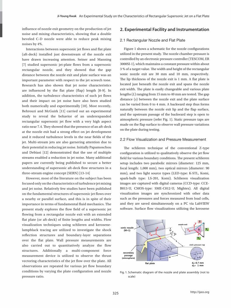
Figure 1 shows a schematic for the nozzle configurations
utilized in the present study. The nozzle chamber pressure is
controlled by an electronic pressure controller (TESCOM, ER
3000SI-1), which maintains a constant pressure within about
3 % of a target value. The width and height of the rectangular
sonic nozzle exit are 30 mm and 10 mm, respectively.
The lip thickness of the nozzle exit is 1 mm. A flat plate is
located just beneath the nozzle exit and spans the nozzle
exit width. The plate is easily changeable and various plate
lengths (L) ranging from 15 mm to 40 mm are tested. The gap
distance (s) between the nozzle exit and the plate surface
can be varied from 0 to 4 mm. A backward step thus forms
naturally between the nozzle exit lip and the flap surface,
and the upstream passage of the backward step is open to
atmospheric pressure (refer Fig. 1). Static pressure taps are
made on the flap surface to observe wall pressure variations
on the plate during testing.
2.2 Flow Visualization and Pressure Measurement
The schlieren technique of the conventional Z-type
configuration is utilized to qualitatively observe the jet flow
field for various boundary conditions. The present schlieren
setup includes two parabolic mirrors (diameter: 125 mm,
focal length: 1,000 mm), two optical mirrors (diameter: 90
mm), and two light source types (LED-type: K-STL, Komi,
spark-bulb type: LS-201, Komi). Schlieren visualization
images are captured with digital cameras (CCD-type: CCE-
B013-U, CMOS-type: SME-C012-U, Mightex). All digital
visualization images are synchronized with other data
such as the pressures and forces measured from load cells,
and they are saved simultaneously on a PC via LabVIEW
software. Surface flow visualizations utilizing the kerosene
4
maintains a constant pressure within about 3 % of a target value. The width and height of the
rectangular sonic nozzle exit are 30 mm and 10 mm, respectively. The lip thickness of the nozzle exit
is 1 mm. A flat plate is located just beneath the nozzle exit and spans the nozzle exit width. The plate
is easily changeable and various plate lengths (L) ranging from 15 mm to 40 mm are tested. The gap
distance (s) between the nozzle exit and the plate surface can be varied from 0 to 4 mm. A backward
step thus forms naturally between the nozzle exit lip and the flap surface, and the upstream passage of
the backward step is open to atmospheric pressure (refer Fig. 1). Static pressure taps are made on the
flap surface to observe wall pressure variations on the plate during testing.
Fig. 1 Schematic diagram of the nozzle and plate assembly (not to scale)
2.2 Flow Visualization and Pressure Measurement
The schlieren technique of the conventional Z-type configuration is utilized to qualitatively observe
the jet flow field for various boundary conditions. The present schlieren setup includes two parabolic
mirrors (diameter: 125 mm, focal length: 1,000 mm), two optical mirrors (diameter: 90 mm), and two
light source types (LED-type: K-STL, Komi, spark-bulb type: LS-201, Komi). Schlieren visualization
images are captured with digital cameras (CCD-type: CCE-B013-U, CMOS-type: SME-C012-U,
Mightex). All digital visualization images are synchronized with other data such as the pressures and
forces measured from load cells, and they are saved simultaneously on a PC via LabVIEW software.
Surface flow visualizations utilizing the kerosene and lampblack tracing technique are also conducted
to investigate the surface flow patterns on the plate. The medium used for the technique is a
Fig. 1. Schematic diagram of the nozzle and plate assembly (not to scale)

DOI: http://dx.doi.org/10.5139/IJASS.2016.17.3.324 326
Int’l J. of Aeronautical & Space Sci. 17(3), 324–331 (2016)
and lampblack tracing technique are also conducted to
investigate the surface flow patterns on the plate. The
medium used for the technique is a combination of
kerosene, lampblack and small amounts of a silicone oil. The
pressures of the nozzle stagnation chamber and on the plate
surface are measured using a pressure scanner (PSI 9116,
Measurements Specialties) at a 60 Hz sampling rate, and
they are also synchronized with other experimental data.
The maximum measurement uncertainty of the pressure
scanner is reported to be in the range of ±1.0 kPa.
2.3 Force Measurement
A salient feature of the supersonic jet flow on the plate
is the occurrence of shock reflections and boundary-layer
separations over the plate surface. The varying wall pressures
that develop on the plate as a result of such complicated flow
structures can introduce a net vertical force to act on the plate,
i.e., the downstream of the jet flow can be deflected upwards
or downwards, depending on specific boundary conditions.
In the present study, the nozzle block is assembled with a
force measurement zig to investigate the applicability of the
supersonic jet flow with the plate (flap) for thrust vectoring
controls.
The present nozzle assembly and force measurement
device use a vertical type design. The schematic diagram
of the test chamber is shown in Fig. 2. A counter-balance
weight is attached to align the axis of the center of gravity
of the assembly to the load cells installed at the bottom of
the nozzle block, thereby enabling the tare loads transmitted
to the side load cells to be eliminated. Signals from the four
load cells (CAS) in the test device are digitally recorded by
a bridge-circuit module (NI 9237, NI) at a 1 kHz sampling
rate. The pivot points of the two load cells measuring the side
thrust are aligned to the nozzle exit plane, and two S-type
load cells installed at the bottom center of the nozzle block
measure the axial thrust.
Detailed calibrations and data analyses are performed
to quantitatively estimate the measurement errors in the
test device. The standard deviations and the repeatability
of each element in the coefficient matrix used in the thrust
calculation procedure are less than 1 %. For all calibration
loading conditions, the value of the interaction coefficients
(the off-diagonal term of the coefficient matrix) is less than
1 % of the value of the direct coefficients (the diagonal term
of the coefficient matrix). The overall maximum error of the
present force measurement system is approximately in the
range of 6-7 %. More detailed information, including the
calibration procedure and the error analysis of the present
test device, can be found in Reference [15].
3. Results and Discussion
3.1 Flow Structures for Various Plate Lengths and NPRs
All results described below are obtained for a sonic nozzle
and constant nozzle stagnation temperature near 290 K
during the tests. The schlieren images in Fig. 3 compare the
jet flow structures over the plate for various plate lengths and
NPRs. Here, NPR refers to the ratio of the nozzle stagnation
pressure to the atmospheric pressure. The jet flow direction
is left to right, and the white lines outline the plate. The plate
surface tightly touches the nozzle exit lip in all cases, and
thus the gap distance (s) is 0, if not mentioned otherwise.
Figure 3a is the reference case for comparison, in which no
plate is installed at the nozzle exit. As shown in Figs. 3b to 3d,
the plate length imposes a substantial influence on the highly
compressible jet flow structures. As depicted in the third row
of Fig. 3b, for an example, a strong oblique shock occurs at
the end of the plate (deck shock). It is observed that the deck
shock interacts with another shock just behind it, forming
a lamda-shock structure. The jet flow is slightly displaced
upward with a thick shear layer at the end of the plate. The
shock structure in the jet flow field shows noticeable changes
as the plate length increases. As shown in Fig. 3c, the oblique
shock on the plate moves slightly downstream as the plate
length increases to L = 2.5H. As depicted in the second row of
Fig. 3c, an expansion wave (visible in the dark region in the
schlieren image) forms at the end of the plate. The overall jet
flow then deflects downward. As the plate length increases
further up to L = 4.0H, the previous jet deflection patterns
diminish, and the jet flow always deflects slightly upward,
irrespective of NPR values. It is obvious that the jet deflection
at the end of the plate is influenced by the changes of the
shock cell pattern and the boundary-layer separation of the
jet.
Although the schlieren images provide significant insight
into the global flow structures, they are path integral of
the density variations of the flow. Therefore, surface flow
6
matrix). The overall maximum error of the present force measurement system is approximately in the
range of 6-7 %. More detailed information, including the calibration procedure and the error analysis
of the present test device, can be found in Reference [15].
Fig. 2 Schematic diagram of the force measurement device
3. Results and Discussion
3.1 Flow Structures for Various Plate Lengths and NPRs
All results described below are obtained for a sonic nozzle and constant nozzle stagnation
temperature near 290 K during the tests. The schlieren images in Fig. 3 compare the jet flow structures
over the plate for various plate lengths and NPRs. Here, NPR refers to the ratio of the nozzle
stagnation pressure to the atmospheric pressure. The jet flow direction is left to right, and the white
lines outline the plate. The plate surface tightly touches the nozzle exit lip in all cases, and thus the
gap distance (s) is 0, if not mentioned otherwise.
Figure 3a is the reference case for comparison, in which no plate is installed at the nozzle exit. As
shown in Figs. 3b to 3d, the plate length imposes a substantial influence on the highly compressible
jet flow structures. As depicted in the third row of Fig. 3b, for an example, a strong oblique shock
occurs at the end of the plate (deck shock). It is observed that the deck shock interacts with another
shock just behind it, forming a lamda-shock structure. The jet flow is slightly displaced upward with a
thick shear layer at the end of the plate. The shock structure in the jet flow field shows noticeable
changes as the plate length increases. As shown in Fig. 3c, the oblique shock on the plate moves
slightly downstream as the plate length increases to L = 2.5H. As depicted in the second row of Fig.
Fig. 2. Schematic diagram of the force measurement device

327
Ji-Young Kwak An Experimental Study on the Characteristics of Rectangular Supersonic Jet on a Flat Plate
http://ijass.org
visualizations on the plate surface are carried out using
the kerosene-lampblack tracing technique. Fig. 4 presents
several examples, in which the top view of the streaklines on
the L=2.5H plate surface for various NPRs are represented.
No appreciable streakline pattern has been noticed if
the plate length is as short as L=1.5H. At a 300 kPa nozzle
pressure (NPR=3.0), the compression waves reflected from
the underexpanded upper jet boundary form a weak oblique
shock on the plate as shown in Fig. 4a. A weak separation
and reattachment of the jet boundary layer on the plate is
shown with a thin parallel separation bubble merging to the
centerline (visible in the bright layer in the streakline pattern).
The jet boundary on the plate afterward is curved toward to
the plate centerline, causing a strong spanwise inflow from
the atmosphere. Strong flow separations are not noticed in
this case, and the jet flow deflects downward at the end of the
plate. As the NPR increases to 4.0, the overall shock structure
shows a drastic change. The shock gets stronger and wider
in the spanwise direction, and it moves slightly upstream
to stand near x=1.75H. A pair of counter-rotating vortices
symmetric to the centerline and separated from the plate is
shown behind the shock. It is clearly shown that the jet core
associated with the separation deflects upward at the end of
the plate. The change in the overall shock structure between
NPR=3.0 and NPR=4.0 is mainly attributed to the sudden
change in the jet deflection at the end of the plate. Very
little difference is observed in the overall surface streakline
pattern for a higher NPR of 4.5 (see Fig. 4c).
Similarly, Fig. 5 shows the streaklines on the L=4.0H
plate for various NPRs. The black dots in the figure denote
7
3c, an expansion wave (visible in the dark region in the schlieren image) forms at the end of the plate.
The overall jet flow then deflects downward. As the plate length increases further up to L = 4.0H, the
previous jet deflection patterns diminish, and the jet flow always deflects slightly upward, irrespective
of NPR values. It is obvious that the jet deflection at the end of the plate is influenced by the changes
of the shock cell pattern and the boundary-layer separation of the jet.
(a) L = 0 (b) L = 1.5H (c) L = 2.5H (d) L = 4.0H
Fig. 3 Schlieren images for various plate lengths and NPRs
Although the schlieren images provide significant insight into the global flow structures, they are
path integral of the density variations of the flow. Therefore, surface flow visualizations on the plate
surface are carried out using the kerosene-lampblack tracing technique. Fig. 4 presents several
examples, in which the top view of the streaklines on the L=2.5H plate surface for various NPRs are
represented. No appreciable streakline pattern has been noticed if the plate length is as short as
L=1.5H. At a 300 kPa nozzle pressure (NPR=3.0), the compression waves reflected from the
underexpanded upper jet boundary form a weak oblique shock on the plate as shown in Fig. 4a. A
weak separation and reattachment of the jet boundary layer on the plate is shown with a thin parallel
(a) L = 0 (b) L = 1.5H (c) L = 2.5H (d) L = 4.0HFig. 3. Schlieren images for various plate lengths and NPRs
8
separation bubble merging to the centerline (visible in the bright layer in the streakline pattern). The
jet boundary on the plate afterward is curved toward to the plate centerline, causing a strong spanwise
inflow from the atmosphere. Strong flow separations are not noticed in this case, and the jet flow
deflects downward at the end of the plate. As the NPR increases to 4.0, the overall shock structure
shows a drastic change. The shock gets stronger and wider in the spanwise direction, and it moves
slightly upstream to stand near x=1.75H. A pair of counter-rotating vortices symmetric to the
centerline and separated from the plate is shown behind the shock. It is clearly shown that the jet core
associated with the separation deflects upward at the end of the plate. The change in the overall shock
structure between NPR=3.0 and NPR=4.0 is mainly attributed to the sudden change in the jet
deflection at the end of the plate. Very little difference is observed in the overall surface streakline
pattern for a higher NPR of 4.5 (see Fig. 4c).
(a) NPR=3.0 (b) NPR=4.0 (c) NPR=4.5
① weak separation shock, ② jet boundary, ③ jet core, ④ counter-rotating vortices, ⑤ atmosphere bleeding, ⑥ strong oblique shock
Fig. 4 Schlieren images and surface streaklines for various NPRs (L=2.5H, s=0)
Similarly, Fig. 5 shows the streaklines on the L=4.0H plate for various NPRs. The black dots in the
figure denote the static pressure holes drilled in the plate. When the NPR is equal to 3.0 with the
(a) NPR=3.0 (b) NPR=4.0 (c) NPR=4.5① weak separation shock, ② jet boundary, ③ jet core, ④ counter-rotating vortices, ⑤ bleeding, ⑥ strong oblique shockFig. 4. Schlieren images and surface streaklines for various NPRs (L=2.5H, s=0)

DOI: http://dx.doi.org/10.5139/IJASS.2016.17.3.324 328
Int’l J. of Aeronautical & Space Sci. 17(3), 324–331 (2016)
the static pressure holes drilled in the plate. When the NPR
is equal to 3.0 with the longer plate length, a substantial
change in the overall shock structure appears as compared
to the previous shorter plate length (see Fig. 4a). The flow
structure now includes a strong separation shock, a pair of
counter-rotating vortices with two clear symmetric foci and
a saddle point just behind the vortices. These features are
similar to those seen in Figs. 4b and 4c. The jet boundary
on the plate is again curved toward to the plate centerline,
causing a strong spanwise inflow from both sides of the plate.
As the NPR increases from 3.0 to 4.0, the streaklines from
the nozzle exit show a more divergent pattern. In addition,
the strong separation shock, vortices and saddle point
move further downstream. The spanwise inflows from the
plate sides, which were previously strong, become weaker,
and the jet boundary extends to the sides of the plate. Very
little difference is observed in the overall surface streakline
pattern for the higher NPR of 4.5 (see Fig. 5c).
Strong spanwise atmospheric bleeding influences the
overall flow structures, and it is apparent that the jet-plate
flow is three-dimensional. To examine the effects of plate
width on the three-dimensional structures on the jet-plate
flow, a wider plate (the plate width = 10H) is installed at the
nozzle exit instead of the previous plate (the plate width =
3H), and similar observations are carried out. No noticeable
changes in the overall flow structures between the two cases
are seen, except for a weak separation shock that moves
slightly upstream in the case with the wider plate. Therefore,
it is concluded that plate width does not significantly
influence the overall jet flow structures on the plate, if it is
larger than the nozzle width.
Wall static pressures along the centerline of the plate are
measured for various NPRs and plate lengths to investigate
the flow structures more quantitatively. The results are shown
in Fig. 6. For L = 2.5H as shown in Fig. 6a, the wall pressures
initially decrease downstream due to the underexpanded
jet conditions. As the NPR value increases, the wall pressure
also increases. The pressures suddenly increase as the
flow crosses the separation shock near x/H = 1.75, where x
denotes the axial distance from the nozzle exit. The locations
of the sudden increase in pressure match well with the shock
locations in the surface streaklines shown in Fig. 4.
For L = 4.0H as shown in Fig. 6b, the initial decrease of the wall
pressure looks similar to that of the previous case shown in Fig.
6a. When the NPR is equal to 3.0, the pressure increases as the
flow crosses the separation shock near x/H = 1.75. The pressure
maintains a monotonous increase downstream through the
vortex region, reaching to a maximum value up to a P/Patm near
9
longer plate length, a substantial change in the overall shock structure appears as compared to the
previous shorter plate length (see Fig. 4a). The flow structure now includes a strong separation shock,
a pair of counter-rotating vortices with two clear symmetric foci and a saddle just behind the vortices.
These features are similar to those seen in Figs. 4b and 4c. The jet boundary on the plate is again
curved toward to the plate centerline, causing a strong spanwise inflow from both sides of the plate.
As the NPR increases from 3.0 to 4.0, the streaklines from the nozzle exit show a more divergent
pattern. In addition, the strong separation shock, vortices and saddle point move further downstream.
The spanwise inflows from the plate sides, which were previously strong, become weaker, and the jet
boundary extends to the sides of the plate. Very little difference is observed in the overall surface
streakline pattern for the higher NPR of 4.5 (see Fig. 5c).
(a) NPR=3.0 (b) NPR=4.0 (c) NPR=4.5
① separation shock, ② jet boundary, ③ counter-rotating vortices, ④ focus, ⑤ saddle point, ⑥ bleeding
Fig. 5 Images of schlieren and surface streaklines for various NPRs (L=4.0H, s=0)
Strong spanwise atmospheric bleeding influences the overall flow structures, and it is apparent that
the jet-plate flow is three-dimensional. To examine the effects of plate width on the three-dimensional
structures on the jet-plate flow, a wider plate (the plate width = 10H) is installed at the nozzle exit
instead of the previous plate (the plate width = 3H), and similar observations are carried out. No
noticeable changes in the overall flow structures between the two cases are seen, except for a weak
(a) NPR=3.0 (b) NPR=4.0 (c) NPR=4.5① separation shock, ② jet boundary, ③ counter-rotating vortices, ④ focus, ⑤ saddle point, ⑥ bleedingFig. 5. Images of schlieren and surface streaklines for various NPRs (L=4.0H, s=0)
10
separation shock that moves slightly upstream in the case with the wider plate. Therefore, it is
concluded that plate width does not significantly influence the overall jet flow structures on the plate,
if it is larger than the nozzle width.
Wall static pressures along the centerline of the plate are measured for various NPRs and plate
lengths to investigate the flow structures more quantitatively. The results are shown in Fig. 6. For L =
2.5H as shown in Fig. 6a, the wall pressures initially decrease downstream due to the underexpanded
jet conditions. As the NPR value increases, the wall pressure also increases. The pressures suddenly
increase as the flow crosses the separation shock near x/H = 1.75, where x denotes the axial distance
from the nozzle exit. The locations of the sudden increase in pressure match well with the shock
locations in the surface streaklines shown in Fig. 4.
(a) L = 2.5H (b) L = 4.0H
Fig. 6 Surface pressure distributions along the plate centerline for various NPRs (s =0)
For L = 4.0H as shown in Fig. 6b, the initial decrease of the wall pressure looks similar to that of
the previous case shown in Fig. 6a. When the NPR is equal to 3.0, the pressure increases as the flow
crosses the separation shock near x/H = 1.75. The pressure maintains a monotonous increase
downstream through the vortex region, reaching to a maximum value up to a P/Patm near 1.3 at x/H
=3.1, and it then begins to decrease. The comparison of the surface streaklines shown in Fig. 5a with
the present pressure variation clearly indicates that the location of the maximum pressure coincides
with the saddle point just behind the vortex bubble. The phenomenon of the pressure decrease after
the vortex bubble is presumed to be due to expansion waves reflected from the upper jet boundary.
(a) L = 2.5H (b) L = 4.0H Fig. 6. Surface pressure distributions along the plate centerline for various NPRs (s =0)

329
Ji-Young Kwak An Experimental Study on the Characteristics of Rectangular Supersonic Jet on a Flat Plate
http://ijass.org
1.3 at x/H =3.1, and it then begins to decrease. The comparison
of the surface streaklines shown in Fig. 5a with the present
pressure variation clearly indicates that the location of the
maximum pressure coincides with the saddle point just behind
the vortex bubble. The phenomenon of the pressure decrease
after the vortex bubble is presumed to be due to expansion
waves reflected from the upper jet boundary. The expansion
waves are visible in a dark region in the corresponding schlieren
image in Fig. 5a. When the NPR is larger than 3.0, the pressure
increase begins later in the axial direction, since the separation
shock moves slightly downstream.
A flow model of the present jet-plate flow can be proposed
to understand the three-dimensional shock structures and
separation on the plate. By combining the schlieren images
and the surface streaklines, the important features regarding
the locations of the weak separation and reattachment of the
jet boundary layer, saddle point, and forming vortices can be
obtained, and the results are shown in Fig. 7. Fig. 7a shows
the flow model of the limiting streamlines on the plate, and
Fig. 7b shows the topological scheme for the case of NPR=4.0
and L =4.0H.
3.2 Jet Flow Thrust Vectoring
Complicated shock reflections and boundary-layer
separation can cause a jet to deflect upwards or downwards,
and they also determine the net vertical force on the plate. If a
simple change of plate configuration, including plate length
and/or gap distance, is able to change the jet deflection
angle, this would enable efficient thrust vectoring control
without the extra power consumption needed to blow/bleed
the secondary control flows. Jet deflection characteristics
are thus quantitatively investigated by utilizing the force
measurement zig in the present study.
The measured deflection angles (δp) are shown in Fig.
8 for various plate configurations. The total uncertainty
of the resultant deflection angles is estimated by the root
sum square of the uncertainties of each Tx and Tz [15],
and the uncertainty bars are put to each datum in the
figures. As shown in Fig. 8a, if the jet is almost perfectly
expanded (NPR = 2.0) and the gap distance (s) is set to
0, very little variation is observed in the jet deflection
angle as a result of the change in plate length. If the NPR
increases to 3.0, the change in the plate length introduces
a substantial change in the pattern of the shock reflections
and boundary-layer separations (refer Fig. 3). The jet
deflects upwards (positive δp) or downwards (negative
δp) according to the variation of plate length. However,
the magnitude of the deflection angles is not that large.
As the NPR increases further to 4.0 and 4.5, the deflection
12
investigated by utilizing the force measurement zig in the present study.
The measured deflection angles (δp) are shown in Fig. 8 for various plate configurations. The total
uncertainty of the resultant deflection angles is estimated by the root sum square of the uncertainties
of each Tx and Tz [15], and the uncertainty bars are put to each datum in the figures. As shown in Fig.
8a, if the jet is almost perfectly expanded (NPR = 2.0) and the gap distance (s) is set to 0, very little
variation is observed in the jet deflection angle as a result of the change in plate length. If the NPR
increases to 3.0, the change in the plate length introduces a substantial change in the pattern of the
shock reflections and boundary-layer separations (refer Fig. 3). The jet deflects upwards (positive δp)
or downwards (negative δp) according to the variation of plate length. However, the magnitude of the
deflection angles is not that large. As the NPR increases further to 4.0 and 4.5, the deflection angle
increases to the maximum value of 7.5° for the case in which L/H equals 1.5. When the NPR has such
high values as 4.0 or 4.5, the deflection angle drops as the plate length increases. However, the jet
always deflects upwards (positive δp values).
Fig. 8 Deflection angles for various plate and NPR configurations
The effects of the gap distance between the nozzle exit lip and the plate surface (or backward step
height) on the variation of the deflection angle are also observed as shown in Fig. 8b. The plate length
is fixed as 1.5H here because the deflection angle is at its maximum in this case, and the angle
becomes weaker as the plate length increases further, as already seen in Fig. 8a. Presently the
secondary passage upstream of the backward step is open to atmospheric pressure. As shown in Fig.
(a) plate length effects (s=0) (b) gap distance s effects (L=1.5H) (a) plate length effects (s=0) (b) gap distance s effects (L=1.5H) Fig. 8. Deflection angles for various plate and NPR configurations
11
The expansion waves are visible in a dark region in the corresponding schlieren image in Fig. 5a.
When the NPR is larger than 3.0, the pressure increase begins later in the axial direction, since the
separation shock moves slightly downstream.
A flow model of the present jet-plate flow can be proposed to understand the three-dimensional
shock structures and separation on the plate. By combining the schlieren images and the surface
streaklines, the important features regarding the locations of the weak separation and reattachment of
the jet boundary layer, saddle point, and forming vortices can be obtained, and the results are shown
in Fig. 7. Fig. 7a shows the flow model of the limiting streamlines on the plate, and Fig. 7b shows the
topological scheme for the case of NPR=4.0 and L =4.0H.
(a) surface flow model (b) 3-dimensional flow model
Fig. 7 Flow model of the jet flow over the flat plate (NPR=4.0, L=4.0H, s=0)
3.2 Jet Flow Thrust Vectoring
Complicated shock reflections and boundary-layer separation can cause a jet to deflect upwards or
downwards, and they also determine the net vertical force on the plate. If a simple change of plate
configuration, including plate length and/or gap distance, is able to change the jet deflection angle,
this would enable efficient thrust vectoring control without the extra power consumption needed to
blow/bleed the secondary control flows. Jet deflection characteristics are thus quantitatively
(a) surface flow model (b) 3-dimensional flow model Fig. 7. Flow model of the jet flow over the flat plate (NPR=4.0, L=4.0H, s=0)
(saddle pt)

DOI: http://dx.doi.org/10.5139/IJASS.2016.17.3.324 330
Int’l J. of Aeronautical & Space Sci. 17(3), 324–331 (2016)
angle increases to the maximum value of 7.5° for the case
in which L/H equals 1.5. When the NPR has such high
values as 4.0 or 4.5, the deflection angle drops as the plate
length increases. However, the jet always deflects upwards
(positive δp values).
The effects of the gap distance between the nozzle exit
lip and the plate surface (or backward step height) on
the variation of the deflection angle are also observed as
shown in Fig. 8b. The plate length is fixed as 1.5H here
because the deflection angle is at its maximum in this
case, and the angle becomes weaker as the plate length
increases further, as already seen in Fig. 8a. Presently the
secondary passage upstream of the backward step is open
to atmospheric pressure. As shown in Fig. 8b, for low NPR
values (2.0 and 3.0) the change in gap distance does not
significantly influence on the jet deflection angle, and the
angle remains almost flat near 0. When the NPR increases
to 4.5, the maximum deflection angle is measured as high
as 7.5° when s is equal to 0, and it decreases almost linearly
as s increases. As depicted in Fig. 9, which shows schlieren
images for various gap distances, the recirculating bubble
just underneath the nozzle exit causes a separation shock
at near the jet’s reattachment location if s increases (see
Fig. 9b). The effect of the backward facing step almost
disappears if s increases up to about 0.4H and the jet
flow expands freely without any interfering with the plate
surface, as depicted in Fig. 9c.
Thrust losses associated with the present jet-plate flows
are also quantitatively observed by estimating the resultant
thrust ratio (Cfg,sys), which is defined as T/Ti. Here T is
the measured resultant thrust (= (Tx2 + Tz
2)0.5) and Ti is the
calculated isentropic axial thrust [16]. In the isentropic axial
thrust calculation, the nozzle exit Mach number is assumed
to be 1.0 since the jet flows are under-expanded for given
NPR conditions. Therefore, the closer to 1.0 the value of the
resultant thrust ratio is, the less the thrust loss is. Irrespective
of the plate lengths and NPR values, the thrust losses due
to the presence of the plate are found to be small, with a
maximum value of about 3.0% (Cfg,sys = 0.97).
4. Conclusions
Flow visualizations and surface pressure/force
measurements are utilized to investigate the structures of
an underexpanded rectangular supersonic jet on a parallel
plate. The effects of various nozzle pressure ratios and plate
configurations on the shock reflections and boundary-layer
separations on the plate are observed, and the following
conclusions are drawn.
(1) A flow model with highly three-dimensional flows is
obtained. A strong separation shock followed by a pair of
counter-rotating vortices and bleeding flows from the plate
sides are observed, and the shock and boundary-layer
separation is attributed to the jet deflections downstream.
(2) For a specific conditon (NPR = 3.0), the jet deflection
is able to be controlled in both upwards and downwards
directions by changing the plate length. However, the
window of the angle variation is narrow.
(3) The plate width does not significantly influence on the
overall jet-plate flow structures, if the width is larger than the
nozzle width.
(4) The change in the gap distance between the nozzle exit
and the plate surface is able to introduce a linear variation
of the jet deflection angle with a maximum positive angle of
about 7.5°. The thrust losses associated with the jet-plate flows
are found to be small, with a maximum value of about 3.0%
Acknowledgement
This research was supported by the Basic Science Research
Program though the National Research Foundation of Korea
(NRF) funded by the Ministry of Education, Science and
Technology (2014-R1A1A2058320).
References
[1] Bridges, J. E., “Acoustic Measurements of Rectangular
Nozzles with Bevel”, AIAA 2012-2252, 33rd AIAA Aeroacoustics
13
8b, for low NPR values (2.0 and 3.0) the change in gap distance does not significantly influence on
the jet deflection angle, and the angle remains almost flat near 0. When the NPR increases to 4.5, the
maximum deflection angle is measured as high as 7.5° when s is equal to 0, and it decreases almost
linearly as s increases. As depicted in Fig. 9, which shows schlieren images for various gap distances,
the recirculating bubble just underneath the nozzle exit causes a separation shock at near the jet’s
reattachment location if s increases (see Fig. 9b). The effect of the backward facing step almost
disappears if s increases up to about 0.4H and the jet flow expands freely without any interfering with
the plate surface, as depicted in Fig. 9c.
(a) s = 0 (b) s = 0.2H (c) s = 0.4H
Fig. 9 Schlieren images for various gap distances (NPR=4.0, L=1.5H)
Thrust losses associated with the present jet-plate flows are also quantitatively observed by
estimating the resultant thrust ratio (Cfg,sys), which is defined as T/Ti. Here T is the measured resultant
thrust (= (Tx2 + Tz
2)0.5) and Ti is the calculated isentropic axial thrust [16]. In the isentropic axial thrust
calculation, the nozzle exit Mach number is assumed to be 1.0 since the jet flows are under-expanded
for given NPR conditions. Therefore, the closer to 1.0 the value of the resultant thrust ratio is, the less
the thrust loss is. Irrespective of the plate lengths and NPR values, the thrust losses due to the
presence of the plate are found to be small, with a maximum value of about 3.0% (Cfg,sys = 0.97).
4. Conclusions
Flow visualizations and surface pressure/force measurements are utilized to investigate the
structures of an underexpanded rectangular supersonic jet on a parallel plate. The effects of various
nozzle pressure ratios and plate configurations on the shock reflections and boundary-layer
(a) s = 0 (b) s = 0.2H (c) s = 0.4HFig. 9. Schlieren images for various gap distances (NPR=4.0, L=1.5H)
331
Ji-Young Kwak An Experimental Study on the Characteristics of Rectangular Supersonic Jet on a Flat Plate
http://ijass.org
Conference, Colorado Spring, CO, June 2012.
[2] Rice, E. J. and Raman, G., “Supersonics Jets
from Bevelled Rectangular Nozzles”, NASA Technical
Memorandum 106403, 1993.
[3] Menon, N., Analysis of Non-axisymmetric
Underexpanded Jet Flow Fields, Ph.D thesis, University of the
Wotwatersrand, Johnnesburg, 2009.
[4] Seiner, J. M., “Fluid Dynamics and Noise Emission
Associated with Supersonic Jets”, Studies in Turbulence,
Springer-Verlag, 1992.
[5] Zaman, K., “Spreading Characteristics of Compressible
Jets from Nozzles of Various Geometries”, J. Fluid Mechanics,
Vol. 383, 1999, pp. 197-228.
[6] Alkislar, M. B., Krothapalli, A. and Louorenco, L. M.,
“Structure of a Screeching Rectangular Jet by a Stereoscopic
Particle Image Velocimetry”, Journal of Fluid Mechanics, Vol.
489, 2003, pp. 121-154.
[7] Seiner, J. M. and Manning, J. C., “Supersonic Jet Plume
Interaction with a Flat Plate”, Proceedings of the international
Power Lift Conference, CA, USA, 1987.
[8] Bridges, J. E., “Noise from Aft Deck Exhaust Nozzle
Differences in Experimental Embodiments”, AIAA 2014-
0876, 52th AIAA Aerospace Meeting, Maryland, USA, Jan 2014.
[9] Zaman, K. B. M. Q., Fagan, A. F., Clem, M. M. and
Brown, C. A., “Resonant Interaction of a Rectangular Jet with
a Flat-plate”, AIAA 2014-0877, 52th AIAA Aerospace Meeting,
Maryland, Jan 2014.
[10] Ibrahim, M. K., Sawai, T., Obase, K., Mori, K. and
Nakamura, Y., “Experimental Investigation of Screech Tone
Characteristics of Jet Interaction with a Flat Plate”, AIAA
Journal, Vol. 47, No. 9, 2009, pp. 2031-2038.
[11] Behrouzi, P. and McGuirk, J. J., “Underexpanded Jet
Development from a Rectangular Nozzle with Aft-deck”,
AIAA Journal, Vol. 53, No. 5, 2015, pp. 1287-1298.
[12] Papamoschou, D. and Debiasi, M., “Noise
Measurements in Supersonic Jets Treated with the Mach
Wave Elimination Method”, AIAA Journal, Vol. 37, 1999, pp.
154-160.
[13] Magstadt, A. S., Berry, M. G., Coleman, T. J., Shea, P.
R., Glauser, M. N., Ruscher, C. J., Gogineni, S. and Kiel, B.
V., “A Near-field Investigation of a Supersonic, Multi-stream
Jet: Locating Turbulence Mechanisms through Velocity
and Density Measurements”, AIAA 2016-1639, 54th AIAA
Aerospace Meeting, CA, Jan 2016.
[14] Stack, C. M., Gaitonde, D. V., Agostini, L., Berry, M. G.,
Magstadt, A. S. and Glauser, M. N., “Numerical Investigation
of a Supersonic Multistream Jet with Aft-Deck”, AIAA 2016-
2058, 54th AIAA Aerospace Meeting, CA, Jan 2016.
[15] Song, M. J., Chang, H. B., Cho, Y. H. and Lee, Y.,
“Development of the High-Accuracy Multi-Component
Balance for Fluidic Thrust Vectoring Nozzle of UAV”, Journal
of the Korean Society for Aeronautical and Space Sciences,
Vol. 41, No. 2, 2013, pp. 142-149.
[16] Flamm, J. D., Deere, K. A., Mason, M. L., Berrier, B.
L. and Johnson, S. K., “Design Enhancements of the Two
Dimensional, Dual Throat Fluidic Thrust Vectoring Nozzle
Concept”, AIAA 2006-3701, 3rd AIAA Flow Control Conference,
CA, USA, June 2006.


