

AN AUTOMATED TOOL FOR HDL AND CONFIGURATION FILE
GENERATION FROM UML SYSTEM DESCRIPTIONS
Approved by:
_________________________________ Dr. Mitchell A. Thornton, Advisor
_________________________________ Dr. Frank Coyle
_________________________________ Dr. Sukumaran Nair

AN AUTOMATED TOOL FOR HDL AND CONFIGURATION FILE
GENERATION FROM UML SYSTEM DESCRIPTIONS
A Thesis Presented to the Graduate Faculty of the
School of Engineering
Southern Methodist University
in
Partial Fulfillment of the Requirements
for the degree of
Master of Science
with a
Major in Computer Engineering
by
Kelly Hawkins
(B.S.E.E., Louisiana State University)
August 1, 2007
iii
Hawkins, Kelly B.S.E.E., Louisiana State University, 2000
An Automated Tool for HDL and Configuration File Generation from UML System Descriptions
Advisor: Professor Mitchell A. Thornton
Master of Science conferred August 1, 2007
Thesis completed June 18, 2007
Model-Driven Architecture (MDA) is a software development approach that
involves creating high-level models that are used for automated system implementation.
The objective of this research is to expand the applicability of MDA to hardware
development. When automation is supported for both hardware and software, MDA has
many applications in modern-day design practices, especially relating to embedded
system design and the necessity of optimally dividing system functionality between
hardware and software.
This project uses Unified Modeling Language (UML) diagrams to define a system
at a high-level. While many tools exist that automatically generate software code in
various languages directly from the UML description, we focus on the generation of low-
level hardware description language (HDL) code for use in the design of application-
specific hardware, typically implemented in programmable logic devices such as CPLDs
and FPGAs.
Our implementation leverages existing tools for formatted text conversion to
generate HDL code for the necessary datapath and control elements of a state-based
system. Additionally, we incorporate industry-leading off-the-shelf software for logic
iv
synthesis and FPGA design flow in order to create a "one-click" conversion tool that
takes a UML system description and converts it directly to a binary file that can be used
to configure programmable hardware.

v
TABLE OF CONTENTS
LIST OF FIGURES ......................................................................................................... viii
LIST OF TABLES...............................................................................................................x
ACKNOWLEDGEMENTS............................................................................................... xi
CHAPTER
1 INTRODUCTION ........................................................................................................1
2 BACKGROUND ..........................................................................................................6
2.1 Model Driven Architecture ...................................................................................6
2.2 Unified Modeling Language (UML) ....................................................................8
2.3 XML and XSLT....................................................................................................9
2.4 Programmable Logic and Hardware Description Languages .............................11
2.5 Sequential Circuit Design ...................................................................................14
3 UML-TO-FPGA TOOL ARCHITECTURE ..............................................................17
3.1 Conversion Process Flow....................................................................................17
3.2 Design Tool Selection.........................................................................................20
4 DESIGN IMPLEMENTATION .................................................................................25
4.1 Stage 1 – UML Design Capture and XMI Export ..............................................25
4.1.1 Datapath Design Capture Conventions.........................................................26
4.1.2 Controller Design Capture Conventions.......................................................31
4.1.3 Exporting XMI..............................................................................................36
4.2 Stage 2 – XMI-to-DAXML Transform...............................................................38
vi
4.2.1 The DAXML Schema ...................................................................................39
4.2.2 Controller Processing....................................................................................43
4.2.3 Datapath Processing......................................................................................46
4.3 Stage 3 – DAXML-to-Verilog Transform ..........................................................54
4.3.1 Datapath Verilog Generation ........................................................................55
4.3.2 Controller Verilog Generation ......................................................................58
4.3.3 Module Parsing, Code Retrieval, and File Separation..................................62
4.4 Stage 4 – Logic Synthesis ...................................................................................65
4.5 Stage 5 – Vendor-Specific Design Flow.............................................................67
4.5.1 Altera Design Flow.......................................................................................68
4.5.2 Xilinx Design Flow.......................................................................................71
4.5.3 Design Flow Clean-up ..................................................................................74
5 TOOL EVALUATION...............................................................................................75
5.1 Running the UML-to-FPGA Tool ......................................................................75
5.2 Testing Methodology..........................................................................................76
5.3 Design Results ....................................................................................................78
6 CONCLUSIONS AND IDEAS FOR FUTURE RESEARCH...................................85
6.1 Future UML-to-FPGA Tool Development .........................................................85
6.1.1 Multiple XMI Format Support......................................................................85
6.1.2 Automatic Constraint File Generation ..........................................................86
6.1.3 Iterative Requirement Satisfaction................................................................88
6.1.4 Design Checking...........................................................................................89

vii
6.1.5 SysML...........................................................................................................91
6.2 Summary .............................................................................................................96
APPENDIX
A UML-TO-FPGA PERL SOURCE CODE .................................................................99
B XMI-TO-DAXML XSLT RULES FILE .................................................................112
C DAXML-TO-VERILOG XSLT RULES FILE........................................................121
D DATAPATH VERILOG SOURCE TEMPLATES.................................................130
REFERENCES ................................................................................................................138

viii
LIST OF FIGURES
Figure
2.1: Synchronous Sequential Circuit Design Elements .............................................. 15
2.2: Example of a Moore Machine.............................................................................. 16
2.3: Example of a Mealy Machine .............................................................................. 16
3.1: UML-to-FPGA Conversion Process Flow........................................................... 18
4.1: A UML-to-FPGA COMPONENT....................................................................... 27
4.2: UML-to-FPGA NET Naming .............................................................................. 29
4.3: A UML-to-FPGA DATARANGE Element......................................................... 30
4.4: A UML-to-FPGA STATE Element ..................................................................... 32
4.5: State Specification Dialog Box............................................................................ 32
4.6: Action Specification Dialog Box ......................................................................... 33
4.7: UML-to-FPGA State Chart with Transitions....................................................... 35
4.8: Excerpt from an XMI File.................................................................................... 37
4.9: DAXML <comments> Structure ...................................................................... 40
4.10: DAXML <state> Element............................................................................. 41
4.11: DAXML <ports> and <wires> Example ................................................... 42
4.12: DAXML <component> Example .................................................................. 43
4.13: XMI "Component" Element............................................................................... 47

ix
4.14: XMI "Dependency" Element ............................................................................. 47
4.15: XMI "Net" Element ........................................................................................... 48
4.16: DAXML <input> Creation Process ............................................................... 50
4.17: DAXML <output> Creation Process............................................................. 52
4.18: Verilog Module "Black Box"............................................................................. 57
4.19: Verilog Constant Declarations ........................................................................... 58
4.20: Verilog Controller State Transition Block ......................................................... 60
4.21: Verilog Controller State Behavior Definition.................................................... 61
4.22: "Source.src" Verilog Source Code Entry........................................................... 64
5.1: Sample UML-to-FPGA Screen Output................................................................ 76
6.1: SysML Model Elements ...................................................................................... 92
6.2: SysML "Blocks", "FlowPorts", and "ItemFlows"................................................ 93
x
LIST OF TABLES
Table
4.1: XMI Paths to DAXML Controller Elements ....................................................... 44
4.2: XMI Paths to DAXML Datapath Elements ......................................................... 46
5.1: UML-to-FPGA Output Files using Altera-specific Synthesis ............................. 79
5.2: UML-to-FPGA Output Files using Synplify Pro Synthesis................................. 79
5.3: Comparison of Automated and Manual Implementation Methods...................... 80
5.4: Comparison of Synthesis Tools using Logic Mapping Parameters ..................... 82
5.5: Comparison of Code Libraries using Mapping and Fitter Parameters................. 83
5.6: Comparison of Synthesis Tools using Timing Parameters .................................. 83
5.7: Comparison of Code Libraries using Timing Parameters.................................... 84

xi
ACKNOWLEDGEMENTS
I would first like to thank Dr. Mitch Thornton for his guidance and support
throughout the process of conceptualizing, researching, and writing this Thesis. I am
very proud of the work that I have been able to accomplish and very grateful to Dr.
Thornton for giving me the opportunity to explore this area of research. Without his
motivation and encouragement, this Thesis would not exist.
Secondly, I would like to thank Dr. Frank Coyle for his enthusiasm for my project
and for introducing me to the world of XML. His hardware/software co-design course
was the true inspiration for this research. I would also like to thank Dr. Sukumaran Nair,
whose kind words and advice have helped guide and motivate my graduate studies from
the day of my very first campus visit at SMU. In addition, I would like to express my
thanks to my classmates, especially to Poramate Ongsakorn, Abhishek Goel, Pallavi
Kulkarni, Laura Spenner, and Matt McPherson, for the assistance, motivation, and
friendship they have given me over the past two years.
I could not have accomplished any of this without the love and support of those
closest to my heart. A special thank you goes to Kristine, for lending an empathetic ear
when stress threatened to get the better of me and for not laughing too hard when her big
brother asked to borrow her GRE preparation books. Also, more than anyone else, Angie
Gray has had to put up with my late nights, my busy weekends, and all of my stress. I am

xii
eternally grateful for her patience, her encouraging words, her meals and snacks, her
insistence that I take a break once in a while, and most importantly, her love.
Finally, I would like to thank my parents. They raised me to place a high priority on
my education, and they set high standards to which I could aspire. Though it has taken a
while, I never once doubted that I could (and would) complete a graduate degree. I
would like to thank my dad for passing on his love for engineering and my mom for
passing on her love for science. More than that, their constant and unconditional love
throughout my life, and especially over the past two years, has given me the strength and
confidence to believe in myself and in my goals. They have always been there to pick me
up when I am down, and to support me in all that I do. For more reasons than one, they
are the reason I am where I am today.

1
Chapter 1
INTRODUCTION
As hardware implementation technology grows continually smaller in scale and
greater in computing power and complexity, embedded system designers are forced to
reevaluate their traditional assumptions regarding the dividing line between software and
hardware utility. As Jerraya and Wolf [1] point out, functions that have been generally
implemented in software can now be realized in hardware with little to no design impact.
Such changes may even result in an increase in design performance. Hardware-
implemented functionality is now required to interface with higher levels of software.
Designers are faced with new choices regarding which functions will be implemented in
software and which will be implemented in hardware.
As the traditional lines of hardware-software separation are blurred, implementation-
related design decisions become increasingly critical. In the past, implementation
choices have been made relatively early in the design cycle. Consequently, separate
specifications were created for each design partition, leading to separate design cycles
and implementation strategies. The traditional assumption that hardware redesign is
more costly and time consuming than software modification has led most embedded
design solutions to be software intensive, as executable code absorbs the majority of late-
coming design revisions and modifications. Such design strategies and assumptions

2
commonly result in disorganized design documentation, complex design verification
processes, sub-optimal design performance, and delayed design release [2].
The field of hardware-software co-design focuses on creating optimal embedded
designs by postponing the actual partitioning of implementation until late in the design
cycle. One proposed methodology is to leverage the concept of Model-Driven
Architecture (MDA) in order to maintain implementation independence throughout most
of the design phase. The MDA design approach specifies the use of high-level modeling
languages, such as UML, to define system requirements, structure, and behavior [3].
Design implementation can then be automated using software conversion processes that
generate low-level code [2]. By designing with an abstract model of various system
parameters, embedded system developers can maintain a single repository of design
documentation, including requirements, design strategies, and, of course, the structural
and behavioral details of the system. Changes in design scope or individual requirements
can be absorbed by high-level models with greater efficiency and less cost than with
previous design paradigms since costly low-level implementation redesign is avoided.
Though MDA was originally conceived as a software design approach, its concept of
implementation independence makes it easily adaptable to hardware-software co-design.
Much work has been done toward defining methods for hardware specification in an
abstract modeling environment [1], including approaches based on the abstraction of
predefined hardware IP components [4] or the use of UML extensions for embedded
hardware [5]. Technological advances in programmable logic devices reduce hardware
time-to-realization and allow for a level of design flexibility that approaches that of
3
software implementations. Therefore, implementation partitioning can now reasonably
be deferred until immediately prior to design implementation.
Due to the software-centric origins of MDA, there are no formal tools extending
support for automated low-level implementation into the field of hardware design.
Reyneri proposes a possible approach to MDA embedded design whereby UML
modeling constructs can be converted to hardware description language (HDL)
representations by mapping them into MATLAB’s Simulink tool [6]. Bjarklund and
Lilius propose a similar mapping conversion using an intermediary language, SMDL [7].
McUmber and Cheng have also proposed a UML mapping to HDL [5]. In each case, the
proposed implementation process stops with an HDL model.
This Thesis presents the framework for a complete MDA-based hardware realization
methodology in the form of a “proof-of-concept” implementation, UML-to-FPGA. The
UML-to-FPGA tool leverages the functionality of industry-leading off-the-shelf software
packages and common scripting languages to produce a design automation application
that not only converts UML design models into HDL code, but also generates a binary
image file which can be used to configure a programmable logic device, thus creating a
fully functional hardware realization of the original design. This work also presents a
new XML schema, Design Automation XML (DAXML), designed specifically to be a
repository for all the information necessary to fully realize a complex sequential circuit
design in hardware.
It should be emphasized that the framework of this automation tool is intended to be
independent of vendor selection for both the target hardware and the third-party tools

4
used in the automation process, in keeping with the ideals of the MDA design approach.
It is assumed that design tool preferences and support for certain packages will vary from
designer to designer and from company to company, so no one design package or
language used in the UML-to-FPGA tool is singularly critical to the successful
completion of the conversion process. Instead, the research presented is intended to show
the general practicality of hardware implementation within the MDA design paradigm, in
that once a design is properly modeled, a fully operational hardware implementation need
only be one “click” away.
Chapter 2 of this Thesis covers background material that may be helpful for
understanding the various design methodologies, languages, and technologies that are
mentioned throughout this work. It will cover the reasoning behind Model-driven
Architecture, and the fundamentals of the Unified Modeling Language (UML) and the
Extensible Markup Language (XML). In addition, there will be an overview of hardware
design using programmable logic and hardware description languages, as well as an
introduction to the basics of sequential circuit design.
Chapter 3 presents a high-level overview of the UML-to-FPGA tool architecture.
Included is a brief description of the operations carried out during each of the five
conversion stages that make up the UML-to-FPGA tool. This overview is followed by a
discussion of the various scripting languages and external tools used in this
implementation and the reasoning behind their selection.
Chapter 4 covers the specific design implementation details that dictate the behavior
of each stage of the UML-to-FPGA tool. This discussion includes detailed information

5
related to design capture conventions, model conversion and synthesis processes, data
formatting, and the usage and invocation of third-party tools. Details of the new
DAXML schema are also presented in this chapter.
Chapter 5 discusses the sample designs used during the development of the UML-to-
FPGA tool and presents a testing methodology for these sample cases. Experimental
results and design synthesis statistics are presented as a supplement to a real-time
demonstration of the tool’s operation.
Chapter 6 concludes the Thesis by presenting several suggestions for areas of future
research into the development and expansion of the UML-to-FPGA tool. The chapter
closes with a summary of the tool implementation covered in this work and its potential
applications for hardware development in a high-level, model-driven design environment.
6
Chapter 2
BACKGROUND
This chapter provides background information on several topics that are referenced
frequently throughout this document. The material covered includes a discussion of
Model Driven Architecture (MDA), as well as the languages most directly related to its
implementation: UML and XML. Also included is material covering programmable
logic implementation and sequential circuit design.
2.1 Model Driven Architecture
Model Driven Architecture, or MDA, is a concept originally intended as a method to
develop software using modeling languages as programming languages [8]. Under this
design approach, high-level graphical models defining the desired software system are
created, and an MDA-based implementation tool is used to automate the generation of the
actual software code that will be compiled and executed [2]. In theory, a systems
engineer should be able to design and implement an entire software system without
knowledge of the underlying code. Such development practices have been used by
industry leaders including IBM, Oracle, Unisys, and IONA to create real-time and
embedded software applications [8].

7
The modeling languages in an MDA design environment are used to generate
platform-independent models (PIMs) of a system. PIMs are designed to describe the
behavior and functionality of an application without using technology-specific code or
structure [3]. By compiling all design information into one model, MDA strives to
facilitate an organized, incremental development process where all design contributions
are integrated into a single entity. It is the goal of MDA that the design could be
implemented on any of a large number of software platforms using only the information
contained within the PIM [2]. Among MDA-supported implementation platforms are
Web Services, XML/SOAP, .NET, CORBA, and J2EE [3].
Object Management Group (OMG), the software consortium driving MDA
development, has defined the MetaObject Facility (MOF) to standardize the basic
structure for modeling design structure, behavior, and data, so that a graphical model of
an application may be appropriately parsed and converted to a structured text format for
transmission over a network. Examples of MOF-compliant languages include the
Unified Modeling Language (UML) and Common Warehouse MetaModel (CWM) [3].
Though originally conceived as a software implementation paradigm, the platform
independence implied in an MDA design model can lend itself to any type of
implementation method. The structure, behavior, and requirements of a design are totally
defined in a PIM, providing source material that is just as sufficient for describing a
hardware system as it is a software application. By including hardware realization as
another available implementation technology, MDA expands into the world of hardware-
8
software co-design and becomes an even more powerful tool for embedded systems
development.
2.2 Unified Modeling Language (UML)
The Unified Modeling Language (UML) was developed by OMG as a tool to specify,
visualize, and document the structure and design of software systems. Software
modeling is intended to be used prior to program coding as a method for “blueprinting”
the application design. Modeling helps designers ensure that application functionality is
complete, correct, and in accordance with end-user requirements, so that the most critical
design decisions can be made using a higher level of abstraction before coding
implementation begins and further modifications become increasingly expensive and
time-consuming. Alternatively, an MDA design approach might be used to link
modeling directly to the implementation process [9].
The latest version of the UML standard defines thirteen diagram types that can be
used for system modeling. These thirteen types can be divided into three basic
categories: Structure Diagrams, Behavior Diagrams, and Interaction Diagrams. Diagrams
in the Structure category include the Class Diagram, the Object Diagram, the Component
Diagram, the Composite Structure Diagram, the Package Diagram, and the Deployment
Diagram. The Behavior Diagram category includes the Use Case Diagram, the Activity
Diagram, and the State Machine Diagram. Diagrams in the Interaction category include
the Sequence Diagram, the Communication Diagram, the Timing Diagram, and the
Interaction Overview Diagram [9].
9
Though originally designed to be a unifying notation for object-oriented software
design, UML can be used for any modeling task where high-level abstraction is
beneficial. There are applications in the business world and, as described in this Thesis,
in the world of hardware development [9]. UML is supported by several tools, including
IBM’s Rational Rose suite [10] and Telelogic’s Rhapsody software [11]. UML models
can be passed between tools, users, or storage media using a XML-based format known
as XML Metadata Interchange (XMI) [9]. The existence of this machine readable XML
structure is critical to the hardware implementation conversion process described in this
Thesis.
2.3 XML and XSLT
Extensible Markup Language (XML) is a flexible text format commonly used for data
transfer across a wide variety of media [12]. Like HTML, XML is a markup language,
where structural tags (textual delimiters encompassed by the “<” and “>” symbols) are
used to identify specific structural elements within a document. However, while HTML
uses a strictly defined set of tags, XML tags are not predefined. Instead, XML allows a
user to define his or her own set of tags, based on the data stored in the document and
how it is intended to be processed. Predefined sets of XML tags do exist, however.
These formats are known as Document Type Definitions (DTDs), or schemas, and are
used to create standardized data transfer and/or representation formats. The focus of
XML is to define a structured method for data storage that allows for simple and explicit
description of the stored information. Because XML is not dependent on any one

10
hardware platform or software application, it is an ideal format for use in applications
requiring data portability and transport [13].
While XML is flexible in terms of the types of structures and tags that can be defined,
its syntax rules are very strict. For instance, all data elements stored in an XML
document must have an opening and closing tag. Other examples of syntax requirements
include rules for describing the proper methods for nesting elements and rules for
formatting element attributes. An XML document that obeys all the specified syntax
rules is said to be “Well Formed” [13].
The structured syntax of XML allows documents to be processed and parsed quickly
and easily. Extensible Stylesheet Language Transformations (XSLT) take advantage of
this structure in order to convert existing Well Formed XML documents into new XML
documents, HTML documents, or any form of plain text format that is desired. The
XSLT language is used to define sets of rules that govern the transformation process [14].
An XSLT rules file is made up of a set of template rules. Each template rule defines
a pattern to be matched within an XML document and a sequence constructor that defines
processing behavior when the match pattern is found in the input XML file. The match
pattern defines an element or set of elements within an XML document. Each time such
an element is found within the original XML document, information relative to that node
is processed based on the actions defined in the sequence constructor, generating material
for the new document being created by the transformation. The parent-child relationship
of tags within an XML document creates a tree-like structure that XSLT must traverse in
order to perform its pattern matching functions. It accomplishes this task with the help of
11
its companion technology, XML Path Language (XPath), which defines a method to
identify and find nodes in an XML document [14]. For example, to help XSLT find the
attribute “name” of the <UML:Model> element that is the child of the
<XMI.content> element, that is in turn, a child of the <XMI> root element of an
XML document, XPath would use the string “/XMI/XMI.content/UML:Model/@name”.
2.4 Programmable Logic and Hardware Description Languages
The invention of the silicon integrated circuit (IC) revolutionized computing
hardware design in the second half of the 20th century, enabling the creation of
increasingly complex digital circuit implementations. Today, most digital hardware falls
into one of two categories: general purpose processors or application specific integrated
circuits (ASICs). General purpose processors are designed to execute a wide variety of
computing functions directed by a set of instructions stored in memory (i.e. software).
ASICs are typically optimized to execute one or a small set of functions for one specific
purpose.
Design cycles for such complex ICs are very costly and time consuming. Once an
original design is completed, it can take weeks or even months to be fabricated, and any
design errors that exist will require another long delay while the corrected silicon is
created. Programmable logic devices (PLDs) provide a solution to such lengthy design
cycles by providing large amounts of logic circuitry with a configurable structure [15].
Modern PLDs can be configured to implement any manner of application-specific digital
circuitry, with the programming process taking a matter of seconds, instead of weeks or

12
months of turnaround time. Thus PLDs provide an excellent medium for development in
an ASIC design cycle, where design turnaround for debugging can happen in as little as
one minute and only the finalized, debugged design is implemented as a fixed-silicon
ASIC [2]. However, it is increasingly common in current digital design practices to use
PLDs as the end-case implementation technology, as they provide “permanent” hardware
design flexibility and allow for “in-the-field” functionality upgrades.
Early PLDs were implemented using arrays of fixed-function logic gates and
configurable interconnections. These programmable logic arrays (PLAs) used
combinations of AND and OR logic gates to implement a wide variety of logic functions.
The first PLA designs were severely limited by the number of logic gates and the
predefined interconnecting wire architecture. Improving the flexibility of these
programmable devices involved adding more logic gates and interconnecting wires.
Today’s complex programmable logic devices (CPLDs) include many blocks of fixed-
function logic gates that are individually configurable and that are interconnected by a
large matrix of interconnecting wires. The increased amount of logic and interconnection
capability allows for the implementation of larger and more complex designs. Even so,
large CPLDs may not be able to support designs requiring more than the equivalent of
20,000 logic gates [15].
Field-programmable gate array (FPGA) technology supports much more logic density
in a single programmable IC. Unlike the fixed-function logic arrays found in CPLDs, an
FPGA provides programmable logic blocks in addition to configurable interconnecting
wires and configurable I/O ports. Typically implemented using SRAM-based look-up

13
tables, multiplexers, and optional memory storage, these logic blocks are arranged in
two-dimensional arrays throughout the IC and are interconnected using rows and
columns of interconnecting wires called “routing channels”. The use of look-up tables
lends additional design flexibility, while the SRAM technology allows for increased logic
density within the FPGA [15].
Programming a CPLD or FPGA involves “downloading” a stream of information into
the device that interacts with internal device structures and configures the various
programmable elements according to the predefined design. This design, for most
programmable devices, is defined using a hardware description language (HDL). An
HDL can be used to express a text-based model of the physical structure and/or temporal
behavior of a digital hardware design [2]. A logic synthesis software tool is then used to
process the HDL model of a design, mapping the described structural and behavioral
design elements to virtual constructs representing the configurable logic elements within
a programmable device [16][17]. Additional software tools, typically issued by the
vendor of a particular FPGA or CPLD, are required to convert this virtual design into a
stream of data that will configure the programmable device to create a physical
implementation of the circuit [18][19].
Though HDLs are used as a means for describing the operation of a digital system,
they are not programming languages. The ability of an HDL to describe a digital system
in terms of its physical structure separates it from high-level languages like C or C++.
Even when used to describe system behavior, an HDL uses descriptions at the register

14
transfer level (RTL), where actions are based on logic levels of physical design elements
instead of virtual “variable” constructs stored in memory banks [17].
Today, there are two commonly used hardware description languages in industry:
Verilog HDL and VHSIC HDL (VHDL). VHDL was initially developed as a language
for documenting the structure and behavior of ICs originally designed using other
methods, but is now an IEEE standardized HDL used for logic design. Verilog HDL
evolved from a proprietary design language, but is also now an IEEE standardized
language in the public domain. Though both VHDL and Verilog are commonly used for
commercial applications, the flexibility and extensibility of Verilog will most likely make
it the HDL of choice in the future [17]. Consequently, Verilog HDL has been chosen as
the language of implementation for the UML-to-FPGA tool described in this document.
2.5 Sequential Circuit Design
Digital circuit implementations may be divided into two distinct categories:
combinational designs and sequential designs. A combinational design is one in which
circuit behavior depends only on the present values of circuit input signals. Sequential
designs are slightly different in that they depend on circuit input signals as well as the
value of some internally stored state information, implying the need for internal memory
elements within the design. The most common form of sequential circuitry utilizes a
global periodic latching signal, or clock, that triggers memory elements to store the
values present on their input ports. Since the clock signal is synchronizing memory state
transitions, implementations using a periodic signal are referred to as synchronous
15
sequential designs [17]. The complexity of most modern digital designs necessitates the
use of some type of internal state machine, so it is important to understand the basic ideas
behind synchronous sequential circuit design.
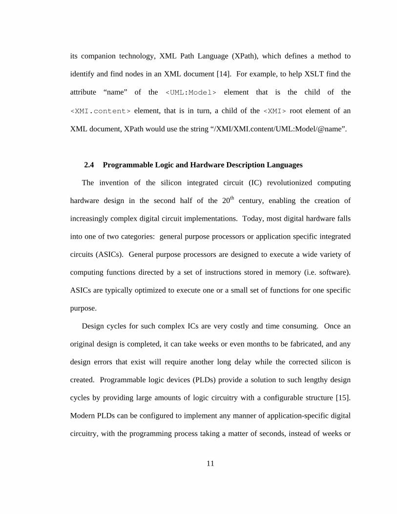
Any synchronous sequential design can theoretically be decomposed into two parts:
the datapath and the controller. The datapath portion of the design is responsible for
transforming input data into output data, while the controller is responsible for governing
the behavior of the datapath. It is the responsibility of the controller to maintain the
internal state of the circuit, and therefore the controller must contain memory elements to
store this information. As shown in Figure 2.1, the controller governs behavior in the
datapath by supplying control signals (e.g. device resets, mux select lines, and register
load and clear signals), but it also accepts feedback signals from the data processing
elements that help determine the next value of the internal state machine [17].
Figure 2.1: Synchronous Sequential Circuit Design Elements
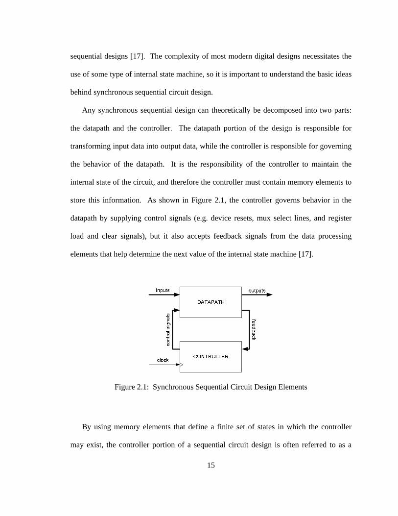
By using memory elements that define a finite set of states in which the controller
may exist, the controller portion of a sequential circuit design is often referred to as a
16
finite state machine (FSM). The controller FSM uses combinational logic to process its
inputs (i.e. top-level design input signals and feedback from datapath elements), along
with the current state information stored in controller memory, and to generate the set of
binary signals that determine its next state of operation. This “next state” value is fed
into controller memory elements, thereby allowing state transitions to occur on the active
edge of the clock signal [17].
Figure 2.2: Example of a Moore Machine
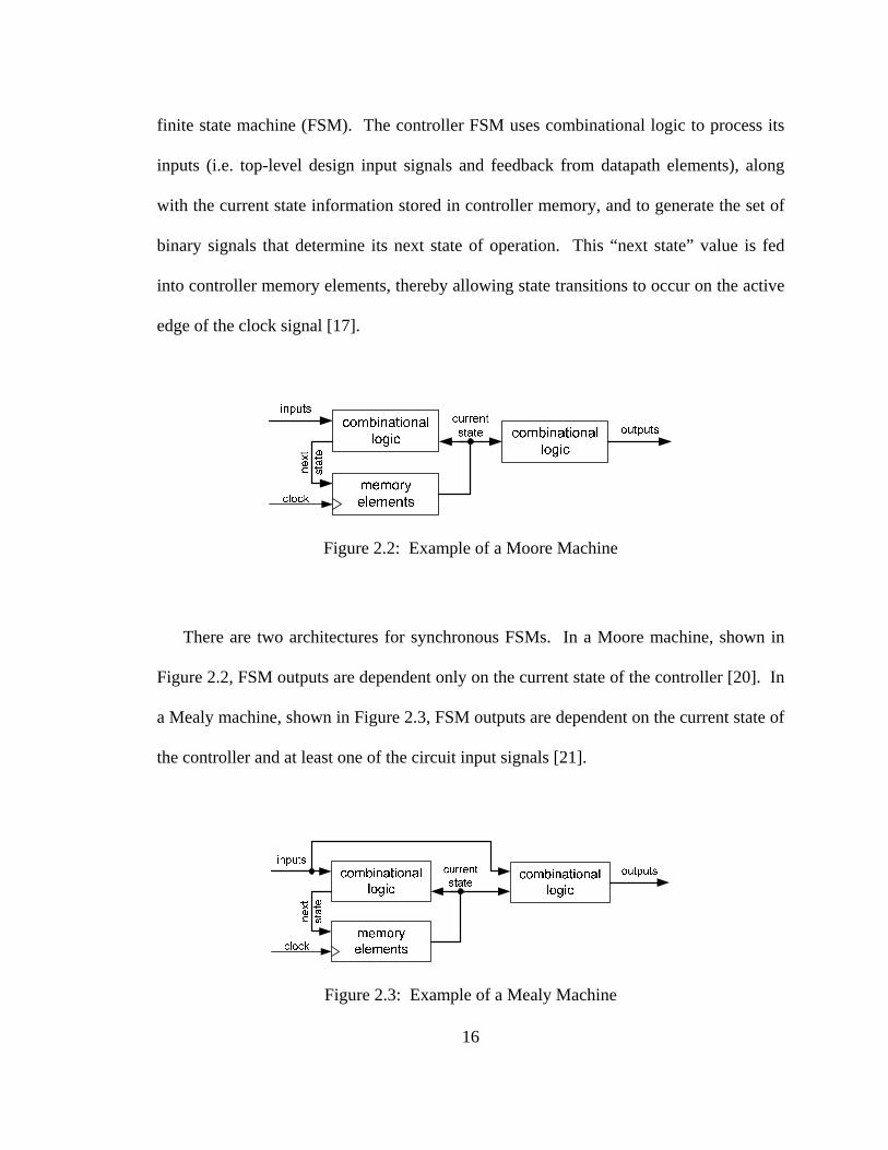
There are two architectures for synchronous FSMs. In a Moore machine, shown in
Figure 2.2, FSM outputs are dependent only on the current state of the controller [20]. In
a Mealy machine, shown in Figure 2.3, FSM outputs are dependent on the current state of
the controller and at least one of the circuit input signals [21].
Figure 2.3: Example of a Mealy Machine

17
Chapter 3
UML-TO-FPGA TOOL ARCHITECTURE
UML-to-FPGA is an automated synthesis tool used for hardware development in an
MDA-based design flow. It processes system-level design descriptions in UML, and,
through a series of conversion stages, generates Verilog HDL source code for the design
and a binary programming file that can be used to configure a programmable logic
device, such as a CPLD or FPGA, to implement the design. Currently implemented as a
command-line script, UML-to-FPGA is a Perl-based tool that integrates design flows
from various state-of-the-art text processing and hardware synthesis software packages to
provide a seamless conversion process with a single command.
3.1 Conversion Process Flow
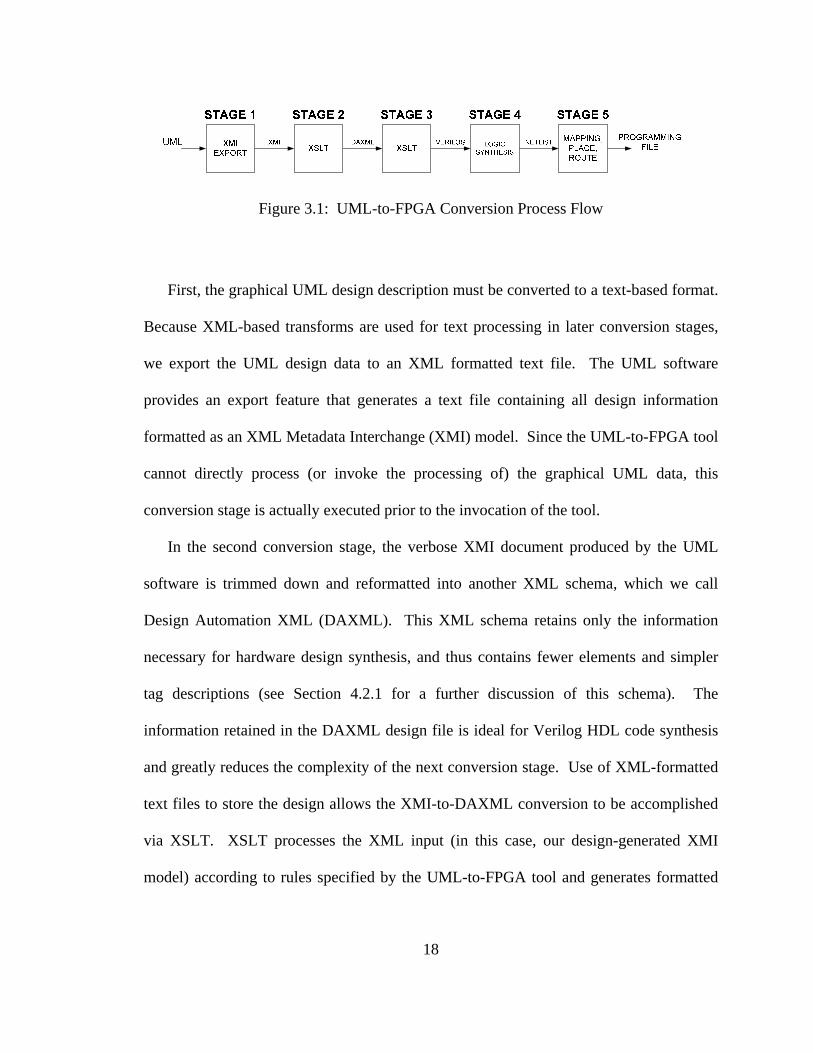
The entire conversion process can be divided into five stages, as shown in Figure 3.1,
below. Once the complete design, including all necessary datapath and control elements,
has been captured using UML modeling software (see Section 3.2 for more information
on the software selected for this implementation), conversion can begin.
18
Figure 3.1: UML-to-FPGA Conversion Process Flow
First, the graphical UML design description must be converted to a text-based format.
Because XML-based transforms are used for text processing in later conversion stages,
we export the UML design data to an XML formatted text file. The UML software
provides an export feature that generates a text file containing all design information
formatted as an XML Metadata Interchange (XMI) model. Since the UML-to-FPGA tool
cannot directly process (or invoke the processing of) the graphical UML data, this
conversion stage is actually executed prior to the invocation of the tool.
In the second conversion stage, the verbose XMI document produced by the UML
software is trimmed down and reformatted into another XML schema, which we call
Design Automation XML (DAXML). This XML schema retains only the information
necessary for hardware design synthesis, and thus contains fewer elements and simpler
tag descriptions (see Section 4.2.1 for a further discussion of this schema). The
information retained in the DAXML design file is ideal for Verilog HDL code synthesis
and greatly reduces the complexity of the next conversion stage. Use of XML-formatted
text files to store the design allows the XMI-to-DAXML conversion to be accomplished
via XSLT. XSLT processes the XML input (in this case, our design-generated XMI
model) according to rules specified by the UML-to-FPGA tool and generates formatted

19
data as output [14]. In this conversion stage, the output format is configured to be
DAXML.
In the third conversion stage, Verilog HDL source code is generated from the
DAXML model of the design. Since DAXML is a valid XML format, XSLT is used
again, invoked with a different set of rules designed to produce synthesizable Verilog
HDL.
Once a synthesizable Verilog HDL model is produced, the design can be
implemented in hardware via logic synthesis. In the fourth conversion stage, off-the-
shelf hardware synthesis software is invoked to convert the HDL code to a structural
hardware model, a gate- or register-level description of design components accompanied
by a netlist defining their interconnection. The UML-to-FPGA tool offers the designer
the option of using one of several available logic synthesis software packages.
In the fifth and final conversion stage, the synthesized logic elements, still described
in a text-based netlist format, are mapped onto programmable logic elements specific to
the selected target device in order to generate a configuration file for the programmable
logic elements it contains. It is therefore necessary at this point in the conversion process
to use the proprietary design software of the chosen IC vendor in order to produce a valid
configuration file for the targeted programmable device. The UML-to-FPGA tool
currently supports targeting Xilinx and Altera devices, and will invoke the correct design
software based on target device selection. Regardless of the selected IC vendor, the fifth
conversion stage contains several steps. First, the hardware components described in the
synthesized netlist are mapped to actual physical components within the selected

20
programmable device. Next, these mapped components are virtually placed and
interconnected in specific locations on the target device. This virtual layout information
is compiled into a vendor-proprietary bit stream that can be downloaded into the target
device in order to configure its internal logic. Once the bit stream is downloaded into the
programmable IC, the designer has a physical implementation of the original UML
design.
3.2 Design Tool Selection
While a detailed description of the UML-to-FPGA tool implementation is presented
in Chapter 4, the following paragraphs will provide an overview of the specific software
tools and languages used in the conversion process described in the previous section.
This overview will include a discussion of the reasoning behind the selection of the tools
in question, as well as the presentation of possible alternative selections for future
implementations.
Developed in the mid-1980s by Larry Wall, Perl is a commonly used scripting
language that bridges the gap between low-level programming languages like C or C++
and high-level programming languages used for shell programming. Originally
developed for Unix-like environments, Perl now has the flexibility to execute both high-
and low-level system tasks in a variety of commonly used operating systems [22]. It
enables the programmer to invoke any third-party software routines from the command
line, as well as to perform the simple file and directory manipulation needed for the
implementation of this conversion tool. Though many scripting languages could have

21
been used, Perl was selected for its simplicity of implementation and its widespread
reference documentation. In addition, Perl provides a powerful text manipulation
command set, which proved invaluable in the file processing tasks required for this
project. Most of the Perl development for this project was done on a Windows-based PC
running the UNIX emulation terminal, Cygwin. The final tool is designed to run in this
emulation terminal environment or on a true UNIX or Unix-like platform.
IBM’s Rational Rose is the UML modeling software package that was selected for
this implementation. The software provides a GUI environment for creating diagrams
using libraries of standardized constructs for the various UML views it supports [10]. Of
particular interest in this project implementation were the Logical and Component Views
supported by the Rose Enterprise Edition, version 7.0.0.0, used to support the capture of
control and datapath elements, respectively. In addition to the basic Rose Enterprise
package, a plug-in is required to add XMI-format export functionality. A wide variety of
UML modeling and development packages exist, including Rational Rose [10] and
Rhapsody from I-Logix/Telelogic [11]. IBM software was selected for this
implementation due to its use in previous incarnations of UML-to-HDL conversion tools
developed by the SMU Hardware-Software Co-Design team [2][23].
XSLT transformations utilized in UML-to-FPGA were implemented using Java-based
Apache Xalan software. Xalan supports full-featured XSLT functionality in a free
package distribution [24]. Xalan is highly portable due to its basis in Java. The
command-line program can run on any OS platform that can support a Java run-time
environment. Many commercially available XML development tools now support XSLT
22
functionality and debugging, but Xalan provided the necessary functionality and
portability at zero cost. However, selection of this tool was based primarily on its use in
previous SMU Co-Design team efforts [2][23].
Synplicity’s Synplify Pro is the industry-leading logic synthesis tool supported as an
optional processing step in the UML-to-FPGA implementation. Synplify uses advanced
synthesis algorithms to maximize logic performance and minimize resource usage in
programmable devices [16]. Widely used in industry, this tool provides support for
synthesis optimizations based on specific programmable logic structures used by leading
CPLD and FPGA vendors like Altera and Xilinx. Consequently, it can be used to
maintain commonality in the logic synthesis process without having to select a specific
programmable logic vendor, and in most cases, Synplify can match the performance of
vendor-provided synthesis tools in terms of design optimization. The package provides a
powerful GUI interface with a wide variety of design development tools; however for the
purposes of UML-to-FPGA implementation, Synplify’s command-line interface is used.
The command-line interface is based on the Tcl (Tool Command Language) scripting
language [25] and requires very basic project definition files and execution formats that
are quite easily generated by the UML-to-FPGA tool’s Perl framework. While it
provides very powerful functionality, Synplify Pro is typically very expensive to
purchase and support. It is an optional feature in the UML-to-FPGA conversion process
because similar functionality is supported in vendor-specific programmable logic design
tools.
23
Before the final stage of the UML-to-FPGA conversion process, a specific
programmable logic vendor must be selected for the design. This project was designed to
support the targeting of devices manufactured by Altera and Xilinx. Each vendor
supplies its own proprietary design software that includes logic synthesis, logic mapping,
place-and-route, and configuration file generation functionality. The design tools
typically provide an entire suite of analysis tools for design creation and constraint
analysis, as well as software and drivers that can be used to physically configure actual
programmable devices. The Altera design tool is known as Quartus-II [18], while the
Xilinx equivalent is called ISE [19].
Altera Quartus-II 6.1 Web Edition design software is typically run using its GUI
interface, which provides design and constraint capture, logic synthesis, and analysis
tools to the user. However, it also supports a Tcl-based command-line interface with
separate executables for each design tool. Design and constraint information is defined in
a Tcl script file, which is then used to generate a project environment that supports the
remainder of the design flow. The command line executables used by the UML-to-FPGA
tool are: quartus_map (Altera’s proprietary logic synthesis and mapping tool),
quartus_fit (Altera’s place-and-route tool), and quartus_asm (Altera’s configuration file
generation tool) [26].
Xilinx ISE WebPACK 8.1i design software provides a GUI design environment
similar to that produced by Altera. However, instead of a Tcl-based scripting interface,
ISE uses its own command-line design flow, called XFLOW. XFLOW uses several
process flow template files to define the execution order and option usage for the tools in
24
the ISE design flow. Like Altera’s Quartus-II software, Xilinx ISE uses individual
executable files for each of its design tools: xst (the Xilinx synthesis tool), ngdbuild
(Xilinx’s tool for building its proprietary circuit descriptions), map (Xilinx’s mapping
tool), par (Xilinx’s place-and-route tool), and bitgen (Xilinx’s configuration file
generation tool) [27].
The selection of the design tools used in the final stage of the UML-to-FPGA
conversion process was based solely on the availability of the hardware development
boards from a particular vendor. At various points during development of this tool,
access was limited to either a Xilinx development board or an Altera development board,
but not both. Consequently, the tool evolved to support design flows for both vendors.
25
Chapter 4
DESIGN IMPLEMENTATION
The previous chapter presented a high-level overview of the operation of the UML-
to-FPGA tool, as well as a list of the tools used for its implementation. Now, we follow
with a detailed, stage-by-stage description of the design methodologies and specifics of
implementation used to create the final tool.
4.1 Stage 1 – UML Design Capture and XMI Export
The function of the first conversion stage in the UML-to-FPGA tool is to export a
graphical system design description, formatted using constructs and rules defined by the
UML standard, to an XML-based textual format so that the design may be processed
correctly in subsequent stages of the conversion. While Rational Rose is responsible for
the actual exporting process, it is important that the design is captured in the correct
format using the proper conventions to produce an XMI output file that will yield a
realized circuit at the end of the conversion process. This section will describe the UML
conventions for valid UML-to-FPGA design capture, as well as the implementation
instructions for the XMI export process.
For the purposes of this Thesis, we will assume that we are dealing with a sequential
design, requiring both datapath and controller elements. Each of these elements will
26
be defined using a different diagram type from among the many defined by the UML
standard. The description of datapath elements and interconnectivity is captured using a
UML Component Diagram. The controller description, in the form of a state machine, is
captured with a UML Statechart Diagram. The following paragraphs will first address
datapath capture then controller state diagram capture. For the purposes of clarity in this
section, complete names of the design elements defined for the UML-to-FPGA tool will
be CAPITALIZED. Standard UML elements will be shown in “quotes” with the first
letter capitalized.
4.1.1 Datapath Design Capture Conventions
Rational Rose supports the UML Component Diagram under the “Component View”
section of a defined UML model. Each datapath component in the design, which will
eventually be converted into a Verilog module instantiated in the top-level design, is
defined using a UML “Component” element. The naming of each such COMPONENT is
critical, as the name will be used to produce the correct HDL source code for the desired
design module during later conversion stages.
Interconnectivity between design components in the datapath is captured using UML
“Dependency” elements, with the DEPENDENCY arrow pointing in the direction of data
flow, which henceforth shall be referred to as “downstream”. Since Rational Rose UML
does not support definition of uniquely named “Dependencies” from a single
“Component” to multiple downstream “Components”, as would be required with any
multi-port datapath module, each main COMPONENT in the captured design must be
27
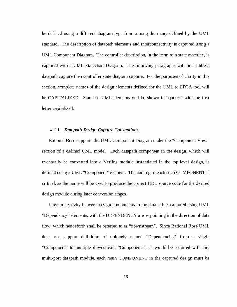
accompanied by PORT subcomponents. A PORT is also defined using a UML
“Component” element and is named using the following convention:
“PORT.componentname.portname[widthdescription=value]”, where componentname is
the parent COMPONENT, portname is the name for the module I/O port being described,
and widthdescription is one of several keywords used to define the width (in bits) of the
PORT. These keywords for width description will be discussed later in this section. The
names for PORTs with a width of one bit should omit the “[widthdescription=value]”
portion of the name. Each PORT is associated with its parent COMPONENT using
unnamed DEPENDENCY elements. These DEPENDENCY elements flow from PORT
to parent COMPONENT element when specifying an input to a design element and from
parent COMPONENT to PORT element when specifying an output from a design
element. Interconnecting nets between COMPONENTs must be routed to these PORT
elements, and not to the COMPONENT itself. An example of a fully defined “dflipflop”
COMPONENT element for UML-to-FPGA is shown in Figure 4.1, below:
Figure 4.1: A UML-to-FPGA COMPONENT

28
Special care must be taken when describing multiple instances of the same
COMPONENT with the same datapath design. Rational Rose will not export multiple
copies of the same element correctly in XMI, so each COMPONENT must have a unique
name. The UML-to-FPGA convention is to use the proper name for the Verilog module,
followed by the “#” symbol and a number. For example, the second instance of
“dflipflop” within a design would be named “dflipflop#2”. The unique naming
convention must also be applied to the componentname field included in the name of any
PORT elements of the COMPONENT.
UML-to-FPGA also supports dynamic port width definition for certain components.
This feature will be discussed in detail in Section 4.3.3, but it should be noted here that
each unique instance of a COMPONENT such as a flip-flop or multiplier may be defined
with a different set of PORT widths. This is true for defined design elements with
functionality that is not dependent on a particular buswidth. The names of the
COMPONENTs must still be numbered to be unique, but the base name of the functional
module does not have to be changed in such cases.
Input and output ports for the top-level datapath design are also defined using UML
“Component” elements. A top-level design input element, or IN, is named using the
following convention: “IN:inputportname”. A top-level design output element, or OUT,
is named using a similar convention: “OUT:outputportname”. IN and OUT elements
may be tied directly to the PORT elements of internal design COMPONENTs.
29
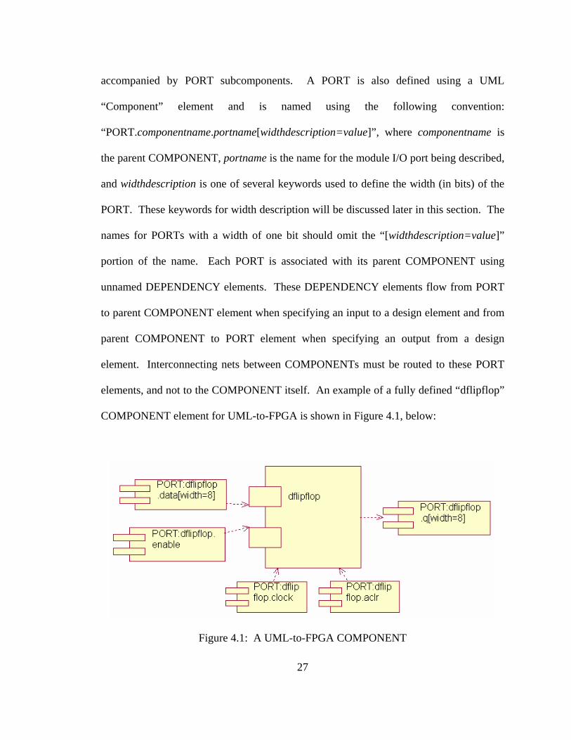
Connectivity between datapath design COMPONENTs is accomplished using
uniquely named UML “Dependency” elements that will be known as NETs. The arrow
for each NET “Dependency” will point in the direction of data flow. NETs are named
using UML “Note” and “Anchor” elements. The unique name should be included in the
“Note” box and associated with a NET using an “Anchor” element, as shown in Figure
4.2. It should be noted that all NETs must have a name and that net widths are not
included in the NET name. NETs connecting IN or OUT elements to internal PORT
elements assume the name of the top-level I/O port and should not be named using a
UML “Note”.
Figure 4.2: UML-to-FPGA NET Naming
Buswidth information for NET, IN, and OUT elements is defined in a separate UML
“Note” element known as a DATARANGE element. An example is shown in Figure 4.3.
The element contains text, starting with the word “DATARANGE” followed by a colon
and then a listing of buswidths for NETs in the design, separated by semicolons. Each
buswidth definition should be of the form: “netname.widthdescription=value”. Any NET

30
with a name not included in the DATARANGE element is assumed to have a width of
one bit. A DATARANGE element is also utilized in the Statechart Diagram used for
Controller design capture.
Figure 4.3: A UML-to-FPGA DATARANGE Element
Ideally, high-level design descriptions such as those intended for use with the UML-
to-FPGA tool would not require such explicit parameter definitions. However, it can be
assumed that the information contained within the DATARANGE element might be
imported and/or derived from other UML models within the system design, particularly
those used to define system requirements. In an effort to demonstrate some of the
requirement interpretation “intelligence” that is built into the UML-to-FPGA tool, three
keywords have been defined to describe the width of busses within the design. First, we
define the explicit width definition keyword, “width”. A NET or PORT with the width
description “width=X” will have a buswidth of X bits in the implemented design. This
description method would typically be used to describe widths of fixed or standardized
values, like those of a processor databus. Second, we define the maximum value
definition keyword, “max”. A NET or PORT with the width description “max=X” will
have a buswidth of CEIL[log2X] bits in the implemented design. This keyword might be

31
used to specify a maximum required counter value or the numeric limit of some stored
value, without having to explicitly define the required number of bits. The third keyword
is “list”, where the width description “list={value1,value2,…}” enumerates the name of
each possible value for the bus. The buswidth in this case would be equal to
CEIL[log2(number of distinct values separated by commas within the braces)]. The “list”
keyword is useful when values or states for a specific NET, IN, or OUT element are
specifically named, rather than numbered.
4.1.2 Controller Design Capture Conventions
Conventions for design capture of controller elements in the UML-to-FPGA tool
were actually defined as part of prior research done to create a tool for automatically
generating synthesizable controller code, as well as design verification assertions, in
SystemVerilog [23]. Since UML-to-FPGA focuses only on creating synthesizable
Verilog, the tool makes use of the subset of these UML capture conventions relating to
the creation of synthesizable HDL. These conventions are described below.
Rational Rose supports the UML Statechart Diagram under the “Logical View –
State/Activity Model” section of a defined UML project model. UML-to-FPGA defines
its sequential controller modules in terms of state machines, so the basic element of UML
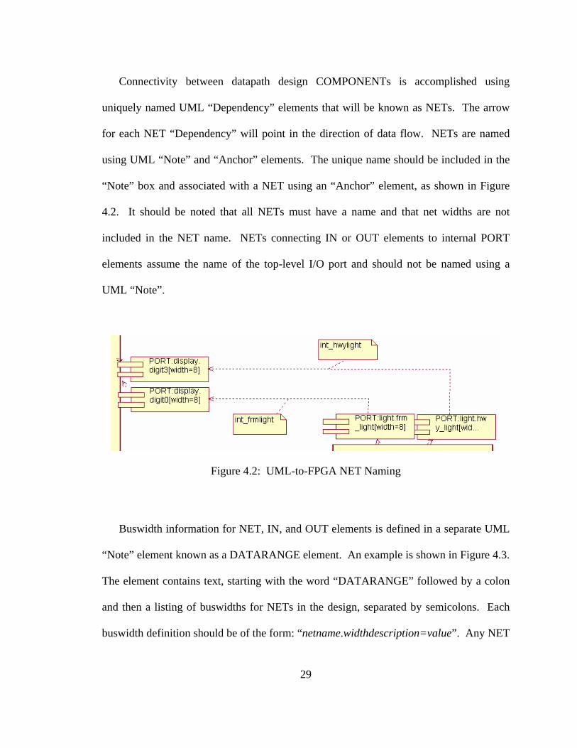
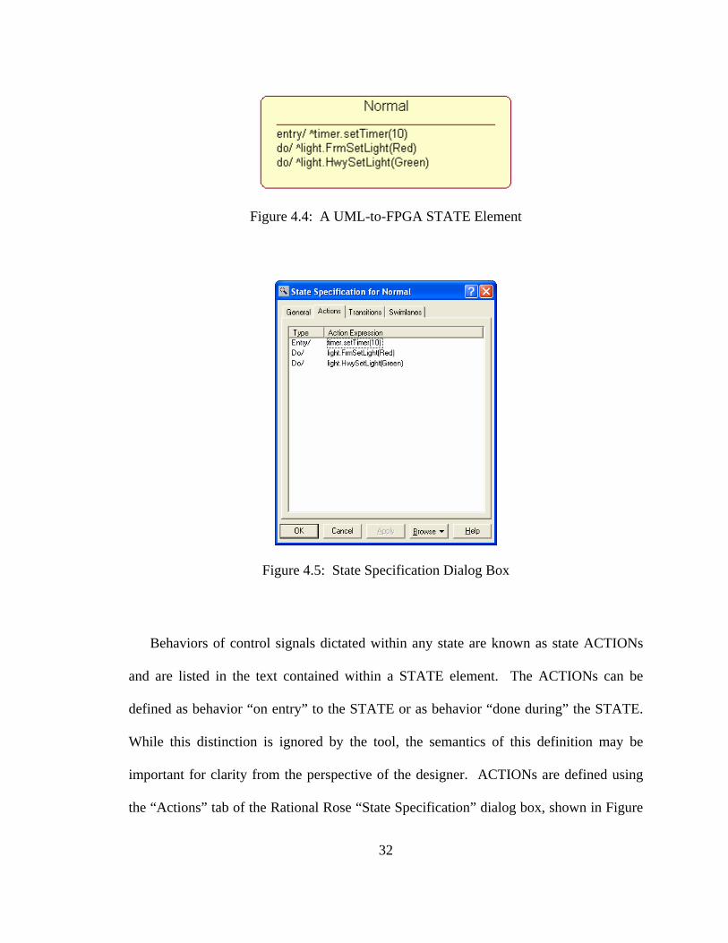
controller design capture is the UML “State” element. Each STATE in the controller
design must be given a unique name. Figure 4.4 shows a typical STATE element used by
the UML-to-FPGA tool.
32
Figure 4.4: A UML-to-FPGA STATE Element
Figure 4.5: State Specification Dialog Box
Behaviors of control signals dictated within any state are known as state ACTIONs
and are listed in the text contained within a STATE element. The ACTIONs can be
defined as behavior “on entry” to the STATE or as behavior “done during” the STATE.
While this distinction is ignored by the tool, the semantics of this definition may be
important for clarity from the perspective of the designer. ACTIONs are defined using
the “Actions” tab of the Rational Rose “State Specification” dialog box, shown in Figure

33
4.5. It should be noted that UML-to-FPGA only supports the creation of Moore machine
controllers.
Figure 4.6: Action Specification Dialog Box
Inserting a new ACTION brings up an “Action Specification” dialog box, as shown in
Figure 4.6, where the type, signals, values, and target of the ACTION are defined. The
“When:” input parameter selects between “Do” and “On Entry” ACTIONs. The “Type:”
parameter must always be “Send Event”. The ACTION “Name:” is the name of the
control signal to which the ACTION applies. This name must correspond to the name of
an output PORT of the controller COMPONENT defined in the datapath design in order
for proper connectivity to be maintained. The “Send arguments:” parameter lists the
value at which the control signal will be set during the current STATE. The signal value

34
is typically defined using one of the elements from a list of possible control signal values
present in the controller model’s DATARANGE element. Finally, the “Send target:”
parameter is used to declare the target COMPONENT for the control signal.
Transitions between states are defined using UML “State Transition” elements.
Arrows for these elements point in the direction of control flow, and the flow can be
defined as conditional or unconditional. An unconditional TRANSITION is defined
using an unnamed “State Transition” element, indicating that the STATE from which the
TRANSITION flows is active for only one clock cycle. Conditional TRANSITIONs are
named using the condition required for state transition. Sample TRANSITION names
might be “roadSensor=Cleared”, “timeout”, or “roadSensor(@timeOut)=Triggered”. In
the first example, we see a condition where a specific controller input (which must
correspond to an input PORT on the controller COMPONENT) is tested against a value
defined in the DATARANGE element. In the second example, the transition will occur if
the defined input signal is logically “true” or “active”. In the third example, a transition
occurs when the first signal condition is true (roadSensor=Triggered) at the same time as
the second condition (timeOut) is active. This transition condition represents a logical
AND. A transition that can be defined as a logical OR is represented using two separate
TRANSITION arrows flowing to the next STATE. Multiple TRANSITION elements
may also be present if different input behavior determines transitions to different
STATEs. Figure 4.7 shows an example of a state machine using some of the state
transition types described above.

35
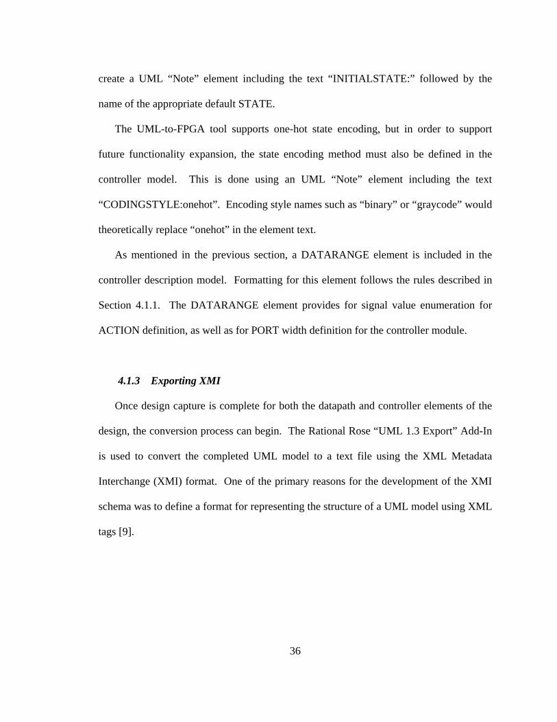
Figure 4.7: UML-to-FPGA State Chart with Transitions
The state to be entered upon initialization of the machine is defined in two ways.
First a UML “Start State” element is inserted with an unconditional TRANSITION
pointing to the default STATE, as shown in Figure 4.7. The second required method is to
36
create a UML “Note” element including the text “INITIALSTATE:” followed by the
name of the appropriate default STATE.
The UML-to-FPGA tool supports one-hot state encoding, but in order to support
future functionality expansion, the state encoding method must also be defined in the
controller model. This is done using an UML “Note” element including the text
“CODINGSTYLE:onehot”. Encoding style names such as “binary” or “graycode” would
theoretically replace “onehot” in the element text.
As mentioned in the previous section, a DATARANGE element is included in the
controller description model. Formatting for this element follows the rules described in
Section 4.1.1. The DATARANGE element provides for signal value enumeration for
ACTION definition, as well as for PORT width definition for the controller module.
4.1.3 Exporting XMI
Once design capture is complete for both the datapath and controller elements of the
design, the conversion process can begin. The Rational Rose “UML 1.3 Export” Add-In
is used to convert the completed UML model to a text file using the XML Metadata
Interchange (XMI) format. One of the primary reasons for the development of the XMI
schema was to define a format for representing the structure of a UML model using XML
tags [9].
37
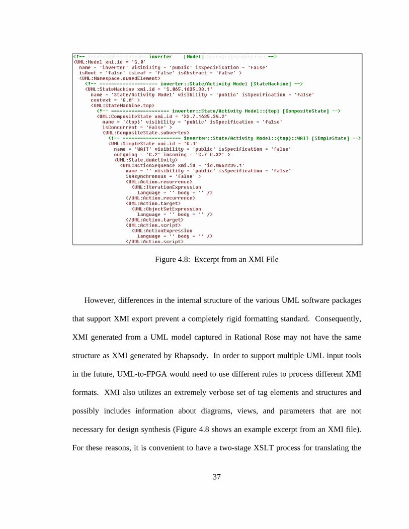
Figure 4.8: Excerpt from an XMI File
However, differences in the internal structure of the various UML software packages
that support XMI export prevent a completely rigid formatting standard. Consequently,
XMI generated from a UML model captured in Rational Rose may not have the same
structure as XMI generated by Rhapsody. In order to support multiple UML input tools
in the future, UML-to-FPGA would need to use different rules to process different XMI
formats. XMI also utilizes an extremely verbose set of tag elements and structures and
possibly includes information about diagrams, views, and parameters that are not
necessary for design synthesis (Figure 4.8 shows an example excerpt from an XMI file).
For these reasons, it is convenient to have a two-stage XSLT process for translating the

38
XMI design model to Verilog HDL. The first of these two stages is described in the
following section.
4.2 Stage 2 – XMI-to-DAXML Transform
The second conversion stage of the UML-to-FPGA tool uses XSLT to process the
XMI-formatted model of the design in order to produce a trimmed down XML model
containing only the essential design information needed for Verilog HDL synthesis.
Splitting the XML translation process into two steps allows much simpler
transformations to be used in each step by separating the task of parsing the verbose XMI
structure from that of generating Verilog HDL. The intermediary XML schema is
adapted from an existing schema known as State Chart XML (SCXML). Developed by
the Voice Browser Working Group, SCXML was designed to provide a generic state-
machine-based notation for use in an XML processing environment [28]. Additions to
the state-machine notation were made to add support for describing datapath structures
and connectivity within the same schema. The modified schema used by the UML-to-
FPGA tool is called Design Automation XML (DAXML). This section describes the
basic elements of the DAXML schema, followed by a detailed discussion of the XSLT
conversion process used in this stage of the UML-to-FPGA tool. The complete XSLT
Rules file for the Stage 2 transform can be found in Appendix B.
39
4.2.1 The DAXML Schema
The main structural tag for the Design Automation XML schema is <daxml>. All
other design description elements used by this schema are children of this master
element. The <daxml> parent element has four types of child elements: <Model>,
<comments>, <state>, and <components>. This section will discuss the contents
and structure of each of these child elements.
Each design contains a single <Model> element. The <Model> element has no
children and contains no value. Instead it possesses a single attribute called “name”. The
“name” attribute stores the name of what will become the top-level design module.
The <comments> element is defined to contain three child elements:
<CODINGSTYLE>, <INITIALSTATE>, and <DATARANGE>. The first two of these
child elements, <CODINGSTYLE> and <INITIALSTATE>, have no children and
contain the values for the state encoding style parameter and the initial state name,
respectively. The <DATARANGE> element has a child element called
<comments.DATARANGE> for each set of unique parameters originally defined in the
DATARANGE box of the UML controller model. Each such element has a “name” and
“maxvalue” attribute corresponding to a controller I/O port. If names are listed for the
values the I/O port can assume, these are included in an attribute called “list”. Figure 4.9
shows an example of a complete <comments> element.

40
Figure 4.9: DAXML <comments> Structure
Within the DAXML schema, there is a <state> element for each defined controller
state. The <state> element has an attribute “id” that contains the name of the state.
There are three defined child elements: <transition>, <assign>, and
<onentry>. Each defined state transition produces a <transition> element that
contains, at a minimum, an “event” attribute containing the name of the signal upon
which the transition depends. The optional attribute “value” is included if the signal
value that triggers a transition is explicitly defined in the UML model. If there is an
additional condition required for the transition to take place, it is included in the attribute
“cond”. Each <transition> element has a single child element, <target>, which
contains the attribute “next”. The “next” attribute defines the state that will be active
after the transition in question. An <assign> element is produced for each “Do” action
defined in the UML controller description for the current state. An <assign> element
has two attributes, “name” and “expr” which define the control signal name and its
assigned value, respectively. Each “On Entry” action defined in the UML state
description is included as an <assign> element. However, these “On Entry”

41
<assign> elements are included as children of the <onentry> element. Figure 4.10
shows an example of a complete <state> element.
Figure 4.10: DAXML <state> Element
The datapath description of the design is almost entirely contained within the
<components> element of the DAXML schema. There are three types of child
elements within the <components> element: <ports>, <wires>, and
<component>. The <ports> element describes the top-level I/O ports in the design
and contains <inputs> and <outputs> child elements. The <inputs> element
contains an <input> element for each top-level input port in the design. Similarly, the
<outputs> element contains an <output> element for each top-level output port.
Within the <wires> element, there is a <wire> element for each unique internal net
defined in the UML datapath model. Buswidths for the ports and nets defined in
<input>, <output>, or <wire> elements are included as part of the name of the port
or net. Figure 4.11 shows examples of complete <ports> and <wires> elements in a
DAXML file.

42
Figure 4.11: DAXML <ports> and <wires> Example
Finally, the <components> element contains a <component> child element for
each datapath module defined in the UML model. Each <component> element has an
attribute “module” that contains the name of the component being defined, as well as two
child elements, <inputs> and <outputs>. The <inputs> element contains an
<input> element for each module input port, and the <outputs> element contains an
<output> element for each module output port. Each <input> or <output>
element contains at least one attribute. The “port” attribute contains the port name of the
parent <input> or <output> element. Additionally, if the defined port has a

43
buswidth greater than one bit, the element contains either a “width” attribute or a
“maxval” attribute that describes this buswidth. The value defined within an <input>
or <output> element is the name of the internal net that is connected to the port being
described. Figure 4.12 shows an example of a <component> element in a DAXML
file.
Figure 4.12: DAXML <component> Example
4.2.2 Controller Processing
The first portion of the XSLT conversion from XMI to DAXML addresses the
creation of the DAXML <Model> element, followed by the controller-related DAXML
elements <comments> and <state>. Table 4.1 lists DAXML controller-related
elements and their respective XPath paths within the XMI input file.
The transformation uses XPath to find the top-level module name within the XMI
input file and define the “name” attribute for the <Model> element. Information used
for the children of the DAXML <comments> element is found using the paths from
Table 4.1. XSLT <xsl:if> statements are used to determine if the matched text

44
contains the text “CODINGSTYLE”, “INITIALSTATE”, or “DATARANGE” in order to
create the correct DAXML element in the output file. Information found for the
<comments.DATARANGE> elements must be tokenized based on the “;” character, and
processed individually using the <xsl:for-each> loops.
Table 4.1: XMI Paths to DAXML Controller Elements
Element XMI Path <Model> /XMI/XMI.content/UML:Model/@name
<comments>
/XMI/XMI.content/UML:Model/UML:Namespace.ownedElement/UML: Comment/@name and /XMI/XMI.content/UML:Model/UML:Namespace.ownedElement/UML: Comment/UML:ModelElement.name
<state> /XMI/XMI.content/UML:Model/UML:Namespace.ownedElement/UML:StateMachine/UML:StateMachine.top/UML:CompositeState/UML:CompositeState. subvertex/UML:SimpleState/
<transition> /XMI/XMI.content/UML:Model/UML:Namespace.ownedElement/UML:StateMachine/UML:StateMachine.transitions/UML:Transition/
@event /XMI/XMI.content/UML:Model/UML:Namespace.ownedElement/UML:SignalEvent/
<onentry>
/XMI/XMI.content/UML:Model/UML:Namespace.ownedElement/UML:StateMachine/UML:StateMachine.top/UML:CompositeState/UML:CompositeState. subvertex/UML:SimpleState/UML:State.entry/UML:ActionSequence/UML:ActionSequence.action/UML:SendAction/
<assign>
/XMI/XMI.content/UML:Model/UML:Namespace.ownedElement/UML:StateMachine/UML:StateMachine.top/UML:CompositeState/UML:CompositeState. Subvertex/UML:SimpleState/UML:State.doActivity/UML:ActionSequence/UML:ActionSequence.action/UML:SendAction/
Each <state> element is found using an <xsl:for-each> loop along with the
path listed in Table 4.1. Within each iteration of this loop, the XSLT process first
identifies all outgoing state transitions for the current state by examining the “outgoing”
attribute of the <UML:SimpleState> element. Transitions are defined in this

45
attribute using the numeric ID assigned by the Rational Rose XMI Export tool.
Information specific to an individual state transition is stored elsewhere in the XMI tree
structure, so the XSLT process must initiate a search along a different path to find the
matching transition ID value.
Once a matching ID value is found, the “target” attribute of the matching element
identifies the XMI ID value for the target, or next, state. In order to find the actual name
of the target state to fully define the <target> child of the <transition> element,
the XSLT process loops through all the XMI state elements to find the matching XMI ID.
Similarly, the “target” attribute of the current transition identifies the XMI ID value for
the signal upon which the transition is based. The XSLT process must search through all
the XMI signal events to find the matching ID, which will lead to the definition of the
applicable “event”, “value”, and “cond” attributes for each DAXML <transition>
element.
Finally, the output control signals defined in the DAXML <onentry> and
<assign> elements are found using the appropriate XMI paths shown in Table 4.1.
The XSLT process loops through each matching instance of this path in order to create
these DAXML elements. Values of “name” and “expr” attributes for each <assign>
element are defined in sub-trees of the currently matched path, so no additional loops to
search for matching ID values are needed. Once all <assign> elements are generated
for a given state, the current <state> element is fully defined, and the transformation
repeats the process for the next unique state defined in the input XMI file.

46
4.2.3 Datapath Processing
There are three XMI elements that are used by the UML-to-FPGA tool to create the
DAXML datapath elements described in Section 4.2.1. For the purposes of describing
the Stage 2 datapath transformation process, these XMI elements, <UML:Component>,
<UML:Dependency>, and <UML:Comment>, will be referred to as “components”,
“dependencies”, and “nets”, respectively. The XMI paths for these elements are listed in
Table 4.2. Each of these XMI datapath elements contains XML attributes that are
necessary for constructing the datapath portion of the DAXML model. The applicable
attributes for each element are discussed in the following paragraphs.
Table 4.2: XMI Paths to DAXML Datapath Elements
DAXML Construct XMI Path component /XMI/XMI.content/UML:Model/UML:Namespace.ownedElement/
UML:Subsystem/UML:Namespace.ownedElement/UML:Component/
dependency /XMI/XMI.content/UML:Model/UML:Namespace.ownedElement/ UML:Subsystem/UML:Namespace.ownedElement/UML:Dependency/
net /XMI/XMI.content/UML:Model/UML:Namespace.ownedElement/ UML:Subsystem/UML:Namespace.ownedElement/UML:Comment/
Each XMI “component” element is assigned a unique alphanumeric XMI ID by the
Rational Rose XMI Exporting process that is stored in the attribute “xmi.id” and that
starts with the letter “S”. The designer-assigned name of the “component” element is
stored in the “name” attribute. The XMI IDs for all incoming “dependency” elements are
listed in the attribute “supplierDependency”, separated by spaces. Similarly, XMI IDs
for all outgoing “dependency” elements are listed in the attribute “clientDependency”,

47
separated by spaces. An example of an XMI “component” element is shown in Figure
4.13. It should be noted that there are four varieties of “component” elements found in
the XMI input file: component modules, component ports (containing the text “PORT:”
in the name), top-level input ports (containing the text “IN:” in the name), and top-level
output ports (containing the text “OUT:” in the name).
Figure 4.13: XMI "Component" Element
XMI “dependency” elements are assigned XMI IDs beginning with “G” and are
stored in the “xmi.id” attribute. These elements are not assigned a name, but contain
critical connectivity information in the attributes “client” and “supplier”. The “client”
attribute stores the XMI ID of the upstream “component” element, and the “supplier”
attribute stores the XMI ID of the downstream “component” element. An example of a
“dependency” element is shown in Figure 4.14.
Figure 4.14: XMI "Dependency" Element

48
XMI “net” elements are assigned XMI IDs beginning with “XX” and are typically
used to store the names of the nets that connect internal datapath modules. The actual net
name is stored in the “name” attribute. The XMI ID of the corresponding “dependency”
element is stored in the “annotatedElement” attribute. An example of a “net” element is
shown Figure 4.15.
Figure 4.15: XMI "Net" Element
The UML-to-FPGA tool begins DAXML datapath generation by defining the top-
level input and output ports. The XSLT process loops through each XMI “component”
element, searching for the text “IN:”. On any such matches, a DAXML <input>
element is created using the “name” attribute of the “component” element. The transform
then finds the XMI <UML:Comment> element containing the text “DATARANGE:”,
and tries to match the port name against the width information stored in the
DATARANGE element. If a match is found, the buswidth is calculated based on the
keyword associated with the port. If the keyword is “width”, then the text “[buswidth:0]”
is appended to the port name in the <input> element, where buswidth is equal to one
less than the value specified in the DATARANGE information. If the keyword
associated with the port name in the DATARANGE block is “max”, then the value for
buswidth is determined using a base-2 logarithm to calculate the maximum number of

49
bits required for the port, and “[buswidth:0]” is appended to the port name in the
DAXML element. If the port name is not listed in the DATARANGE block, the
buswidth is assumed to be one bit, and no information is appended. Once this process is
completed for all input ports, it is repeated for all XMI “component” elements containing
the text “OUT:” in order to generate DAXML <output> elements.
The XSLT process next generates the <wires> element for the DAXML datapath
description by looping through every XMI “net” element and creating a DAXML
<wire> element for each one using XMI “name” attribute. In a process identical to that
described for the top-level ports, the transformation searches through the datapath
DATARANGE element to find buswidth information for the net name, calculates this
buswidth if a match is found, and appends the appropriate information as described in the
previous paragraph.
The Stage 2 XSLT conversion continues with the generation of the DAXML
<component> elements. The transformation process must first search through all the
XMI “component” elements to find the datapath modules (i.e. those without “IN:”,
“OUT:”, or “PORT:” prefixes in the element “name” attribute). For each datapath
module, a DAXML <component> element is created, and the XSLT process must
generate its “module” attribute. Any “#” symbols and subsequent numbers are removed
from the module name to simplify naming conventions, since unique datapath modules
can now be identified by differences in their external connections.
The XSLT process must next define the <inputs> child for each DAXML
<component> element, which requires that both port and associated net names must be

50
found within the XMI input model. The process begins at the XMI “component”
element, and gradually works its way outward, as shown in Figure 4.16. First, the XSLT
process searches through all the XMI “dependency” elements to find any with a
“supplier” attribute containing the XMI ID of the current “component” element (Figure
4.16, Step 1). For each match, the transform generates a DAXML <input> element
and enters a new recursive search stage using the current “dependency” element.
@xmi.id=’S.111’
@xmi.id=’G.789’
@supplier=’S.111’@client=’S.222’@clientDependency
=’G.789’@supplierDependency
=’G.987’
@xmi.id=’S.222’@name=’PORT:xxxxx’
@clientDependency=’G.987’
@xmi.id=’S.333’@name=’PORT:yyyyy’
@xmi.id=’G.987’
@supplier=’S.222’ @client=’S.333’
1
2
3
4
@xmi.id=’XX.123’@name=’zzzzz’
@annotatedElement=’G.987’
5
@name=’wwww’
@supplierDependency=’G.789’
Figure 4.16: DAXML <input> Creation Process
The current “dependency” reflects the association between a design module and its
port component. Using the XMI ID of this “dependency”, the XSLT transform searches
51
through the XMI “component” elements until it finds a matching ID listed in an
element’s “clientDependency” attribute (Figure 4.16, Step 2). This match links the port
“component” with the current module “component”. The XSLT process extracts the port
name and width information from the “name” attribute of the port “component” and uses
it to create “port” and “width” (or “maxval”) attributes for the current DAXML
<input> element.
The final piece of information needed for an <input> element is the name of the
internal net connected to the module port. The transformation process once again
searches through all XMI “dependency” elements to find an XMI ID that matches the
value contained in the “supplierDependency” attribute of the current port “component”
(Figure 4.16, Step 3). The “client” attribute of the matching XMI “dependency” element
is used to determine the source element for the connecting net. The value stored in the
“client” attribute is compared against XMI IDs of all “component” elements (Figure 4.16,
Step 4). If the matching “component” is a top-level input port, its “name” attribute is
parsed to determine the net name assigned to be the value contained in the DAXML
<input> element. If the matching “component” is the port of another design module,
then the net name must be found in an XMI “net” element. The XSLT process must
search through the “annotatedElement” attributes of all “net” elements to find an XMI ID
that matches that of the current net “dependency” (Figure 4.16, Step 5). The “name”
attribute for the matching “net” element is then used to supply the value for the current
DAXML <input> element.
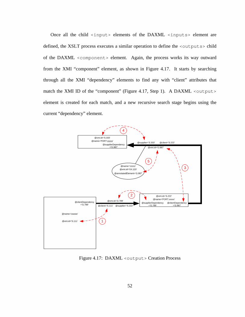
52
Once all the child <input> elements of the DAXML <inputs> element are
defined, the XSLT process executes a similar operation to define the <outputs> child
of the DAXML <component> element. Again, the process works its way outward
from the XMI “component” element, as shown in Figure 4.17. It starts by searching
through all the XMI “dependency” elements to find any with “client” attributes that
match the XMI ID of the “component” (Figure 4.17, Step 1). A DAXML <output>
element is created for each match, and a new recursive search stage begins using the
current “dependency” element.
@xmi.id=’S.111’
@xmi.id=’G.789’
@client=’S.111’ @supplier=’S.222’@clientDependency
=’G.987’@supplierDependency
=’G.789’
@xmi.id=’S.222’@name=’PORT:xxxxx’
@supplierDependency=’G.987’
@xmi.id=’S.333’@name=’PORT:yyyyy’
@xmi.id=’G.987’
@client=’S.222’@supplier=’S.333’
1
2
3
4
@xmi.id=’XX.123’@name=’zzzzz’
@annotatedElement=’G.987’
5
@name=’wwww’
@clientDependency=’G.789’
Figure 4.17: DAXML <output> Creation Process

53
The XSLT transform searches through all “component” elements, trying to find a
“supplierDependency” attribute that matches the XMI ID of the current “dependency”
element (Figure 4.17, Step 2). When a match is found, the “component” is linked to one
of its output ports. The XSLT process extracts the port name and width information from
the “name” attribute of the port “component” and uses it to create “port” and “width” (or
“maxval”) attributes for the current DAXML <output> element.
For the value of the <output> element, the transformation process must search
through all the XMI “dependency” elements to find an XMI ID that matches one of the
values contained in the “clientDependency” attribute of the current port “component”
(Figure 4.17, Step 3). The “supplier” attribute of the matching XMI “dependency”
element is used to find a destination element for the connecting net. The XMI ID stored
in this attribute is compared to the XMI IDs of all “component” elements in the XMI
model (Figure 4.17, Step 4). If the matching “component” is a top-level output port, its
“name” attribute is parsed to find the net name to be assigned to the value of the current
DAXML <output> element. If the matching “component” is the port of another
internal module, then the net name must be found in an XMI “net” element, and the
XSLT process must search for an “annotatedElement” attribute of a “net” element that
contains the XMI ID of the current net “dependency” (Figure 4.17, Step 5). The “name”
attribute of the matching “net” element is then used to supply the value stored in the
DAXML <output> element. When all <output> elements have been defined, the
creation of the current DAXML <component> element is complete. The XSLT
process continues to the next XMI module “component” element until there are none left

54
to be transformed. When all <component> elements have been created, the DAXML
model is complete, and Stage 2 of the UML-to-FPGA tool ends.
4.3 Stage 3 – DAXML-to-Verilog Transform
The third stage of the UML-to-FPGA tool uses XSLT to process the newly created
DAXML model of the design in order to produce a Verilog HDL model of the original
UML design. XSLT <xsl:text> elements are used to generate any constant text
values, such as Verilog keywords, semicolons, and values common to all generated
designs. The XSLT process in Stage 3 generates a single output file, called “output.v”,
containing Verilog modules for each component defined in the original UML model.
However, only the top-level and controller modules are complete at this point in the
stage. The datapath Verilog modules generated by the Stage 3 XSLT are “black boxes”
with only external ports defined. The UML-to-FPGA tool uses Perl processing
subroutines to retrieve Verilog source code for each of these “black boxes”, insert the
source code at the proper locations, and generate separate Verilog files for each unique
functional module in the design. This section describes the XSLT conversion process for
the datapath and controller elements and gives an overview of the Perl processing
subroutines that complete the Verilog HDL source code generation. The complete XSLT
Rules file for the Stage 3 transform can be found in Appendix C.

55
4.3.1 Datapath Verilog Generation
The XSLT conversion from DAXML to Verilog begins with the creation of the top-
level Verilog module. The “name” attribute of the DAXML <Model> element is used
as the name of the top-level module. Verilog requires that all module I/O ports be
included in parentheses as part of the module declaration, so the XSLT process loops
through all child elements from the “/daxml/components/ports/inputs” and
“/daxml/components/ports/outputs” paths, and inserts the values it finds into the Verilog
module declaration. It should be noted that all buswidth information is removed from the
port names before insertion in the module declaration.
The Verilog top-level port definitions follow the module declaration. The XSLT
process loops through the same two paths used in the module declaration, inserting the
appropriate keyword (“input” or “output”) and rearranging the buswidth and port name
information to conform to Verilog syntax rules.
Internal nets are listed next by looping through each child element from the
“/daxml/components/wires” path. Values from the DAXML <wire> elements are
extracted, and the net names and width information are rearranged in the proper Verilog
syntax along with the keyword “wire”. Once the internal nets are defined, internal
functional module instantiations are made.
Modules are extracted by looping through all the <component> elements from the
“/daxml/components” path. The module instances are sorted alphabetically, and each is
assigned a unique reference designator of the form “uX” when it is processed, where X is
a unique numerical identifier. Module instantiations in Verilog must include the module
56
name, the instance name, and port mapping information for each module I/O port. The
module name is extracted from the “module” attribute of each DAXML <component>.
The instance name is created by appending the module name to the reference designator
in the form “uX_modulename”. Port mapping assignments are made by looping through
each <input> and <output> element defined under the DAXML paths
“/daxml/components/component/inputs” and “/daxml/components/component/outputs”,
respectively. Verilog port mapping declarations follow the format “.portname
(netname)”, where portname is extracted from the “port” attribute of the element and
netname is extracted from the value of the element. This instantiation process is repeated
for each <component> element in the DAXML input file.
The top-level Verilog module is complete when all modules have been instantiated.
The XSLT process closes the top-level module with the keyword “endmodule”, and
generates a separator line to help with later parsing operations. The next step for the
Stage 3 transform is to generate “black box” Verilog modules for the individual
component instances in the design. The XSLT process once again loops through the
DAXML <component> elements, generating a new “black box” module for each
datapath module. It should be noted that the “controller” module is ignored during this
process.
The first line for each datapath module is a commented line that lists the instance
reference designator (derived using the same process as described above). The module
declaration uses the Verilog keyword “module” followed by the module name found in
the “module” attribute of the <component> element. The I/O ports are defined by

57
looping through the <input> and <output> elements within the <component>
element and extracting the value of the “port” attribute from each. The same loop is
repeated to extract the port names for the module port declarations. In addition to
extracting the port name from the “port” attribute of the <input> or <output>
element, the port width is extracted from either the “width” or “maxval” attribute. If
either attribute is present, the text “[buswidth:0]” is used in the port declaration. If a
“width” attribute is present, buswidth is equal to one less than the value specified by the
attribute value. If a “maxval” attribute is present, buswidth is calculated by using a base-
2 logarithm to determine the maximum number of bits required to represent the value
stored in the attribute and then subtracting one. If neither “width” nor “maxval”
attributes exist for the element, the buswidth is assumed to be one bit, and no information
beyond the port name is required for the port declaration. The Verilog keyword
“endmodule” is appended after all input and output ports have been declared, and the
Verilog “black box” is complete. A sample “black box” module is shown in Figure 4.18.
When all individual datapath “black boxes” have been created, the transformation begins
generation of Verilog source code for the controller module.
Figure 4.18: Verilog Module "Black Box"

58
4.3.2 Controller Verilog Generation
Controller module Verilog source code generation begins with constant declarations
rather than the module declaration. The Verilog constant declaration syntax is shown in
Figure 4.19. This process begins by encoding the state variables used by the controller
state machine. The XSLT process counts the number of unique <state> elements that
exist in the DAXML model. Because the UML-to-FPGA tool only supports “one-hot”
encoding, each state variable is assigned the number of bits equivalent to the number of
states in the state machine. Verilog constant definitions also include any values
contained in the “list” attribute of <comments.DATARANGE> elements in the DAXML
model. The values in each “list” are separated and individually written to the Verilog
module, where each is assigned a constant numeric value. Value numbering begins at
“0” for each unique “list” attribute found during the XSLT process.
Figure 4.19: Verilog Constant Declarations
59
The XSLT process continues by creating the Verilog controller module declaration.
This particular module is always named “controller”. Names of the controller module
ports are derived from the DAXML model in a manner slightly different from their
datapath counterparts. Input ports are defined using the “event” attribute of
<transition> elements found within each DAXML <state> element. Recall that
the “event” attribute is used to define signals that affect state transitions in the controller
and that such signals serve as inputs to the controller module. The XSLT process lists in
the module declaration the value of each unique, non-empty “event” attribute. Output
ports are defined using the unique “name” attributes of <assign> elements found as
children of either <state> or <onentry> DAXML elements. These “name”
attributes define signals set by the controller and thus represent the output ports of the
module. The module declaration is completed by adding two more input ports present in
any synchronous sequential controller design, “clk” and “reset”.
The XSLT process continues by processing the port declarations for the module. The
“clk” and “reset” ports are automatically defined as inputs, followed by each unique
value found among the “event” attributes of <transition> elements in the DAXML
model. As described in the previous paragraph, output ports are defined in the “name”
attributes of DAXML <assign> elements. The XSLT process also tries to match each
output port name to a “name” attribute from a DAXML <comments.DATARANGE>
element. If a match is found, the “maxValue” attribute from this element is used to
calculate the number of bits needed to represent all possible values for the output signal,
and the information is included in the port declaration to define its buswidth. Since all
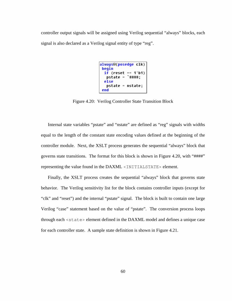
60
controller output signals will be assigned using Verilog sequential “always” blocks, each
signal is also declared as a Verilog signal entity of type “reg”.
Figure 4.20: Verilog Controller State Transition Block
Internal state variables “pstate” and “nstate” are defined as “reg” signals with widths
equal to the length of the constant state encoding values defined at the beginning of the
controller module. Next, the XSLT process generates the sequential “always” block that
governs state transitions. The format for this block is shown in Figure 4.20, with “####”
representing the value found in the DAXML <INITIALSTATE> element.
Finally, the XSLT process creates the sequential “always” block that governs state
behavior. The Verilog sensitivity list for the block contains controller inputs (except for
“clk” and “reset”) and the internal “pstate” signal. The block is built to contain one large
Verilog “case” statement based on the value of “pstate”. The conversion process loops
through each <state> element defined in the DAXML model and defines a unique case
for each controller state. A sample state definition is shown in Figure 4.21.

61
Figure 4.21: Verilog Controller State Behavior Definition
For each <state> element, the XSLT process first uses the “id” attribute to provide
the name of the state. Next, any <onentry> or <assign> elements are found, and the
“name” and “expr” attributes are used to generate the control signal assignments for the
current state. Lastly, DAXML <transition> elements are used to define the next
state for the controller. If the <transition> element has an empty “event” attribute,
then the next state is defined using the value found in the “next” attribute of the
<target> element for the current transition. If the “event” attribute is non-empty, then
the “event”, “value”, and “cond” attributes are used to generate a Verilog “if” statement
of the form “if(event == `value && (cond))”. The “nstate” signal is assigned the value of
the “next” attribute of the transition’s <target> element. In the “else” branch, the
“nstate” signal is assigned the value of the current controller state, so that the state
machine will remain in the current state until the transition condition is true. In the case
in which a <state> element contains more than one <transition> child element,
the XSLT process will generate an “if” statement for the first transition, and an “else if”

62
statement for any subsequent transitions, using the format for the conditional statements
shown above. Once again, the “else” branch assigns to “nstate” the value of the current
state. When all controller states have been defined in Verilog, the XSLT process closes
the case structure with the keyword “endcase” and then closes the entire controller
module with the keyword “endmodule”. This concludes the XSLT portion of the UML-
to-FPGA Stage 3 conversion.
4.3.3 Module Parsing, Code Retrieval, and File Separation
The XSLT conversion produces a single output file containing complete Verilog code
for the top-level design and controller modules, along with Verilog “black boxes” for the
other datapath modules in the design. The final functions of the Stage 3 conversion
process serve to remove duplicate module definitions, separate each module into its own
Verilog source file, and fill in the “black box” modules with Verilog code from the
source repository file. This section will explain each of these functions in detail.
First, a Perl subroutine “Process_Source” is executed to parse the XSLT output file,
“output.v”, in order to find and remove any duplicate module definitions. The subroutine
reads through the entire “output.v” file and creates an array of data structures, each of
which contains the reference designator, module name, input port list, and output port list
for one of the modules in the file. Each data structure also includes two additional
parameters: “dup”, which indicates whether the module is a duplicate, and “var”, which
represents the module variation number. The “dup” parameter is initialized to 0, and the
“var” parameter is initialized to 1.

63
Once these data structures are created, the Perl subroutine processes the data within
them, one array element at a time. As each array element is addressed, the subroutine
searches the following the elements (i.e. those with greater array index values) for
matching values. If the module name, input port list, and output port list match the
current element exactly, then the matching “dup” parameter for the matching array
element (not the current element) is set to 1. In future loop iterations, elements with
“dup” set to 1 are ignored. If the module name matches, but either the input or output
port list varies (this variation should indicate a difference in port width), then the “var”
parameter of the matching array element is incremented to be the next variation of the
module. When the “var” parameter is updated, the module name for the matching array
element must also be updated. If the “var” parameter is not equal to 1, then a double
underscore (“__”) is appended to the module name, followed by the value of the “var”
parameter.
When the processing of each element of the data structure array is complete, all
duplicates will have been found and all variations will have been identified. The
information in the data structure is then used to update the “output.v” file. In the top-
level module, instantiations for modules with “var” parameters greater than 1 are updated
with new module names, as defined in the processed data structure array. The individual
Verilog “black box” modules are also updated with information from the processed data
structure array. Duplicate “black box” modules are removed, and module names are
updated for those modules with “var” parameters greater than 1.
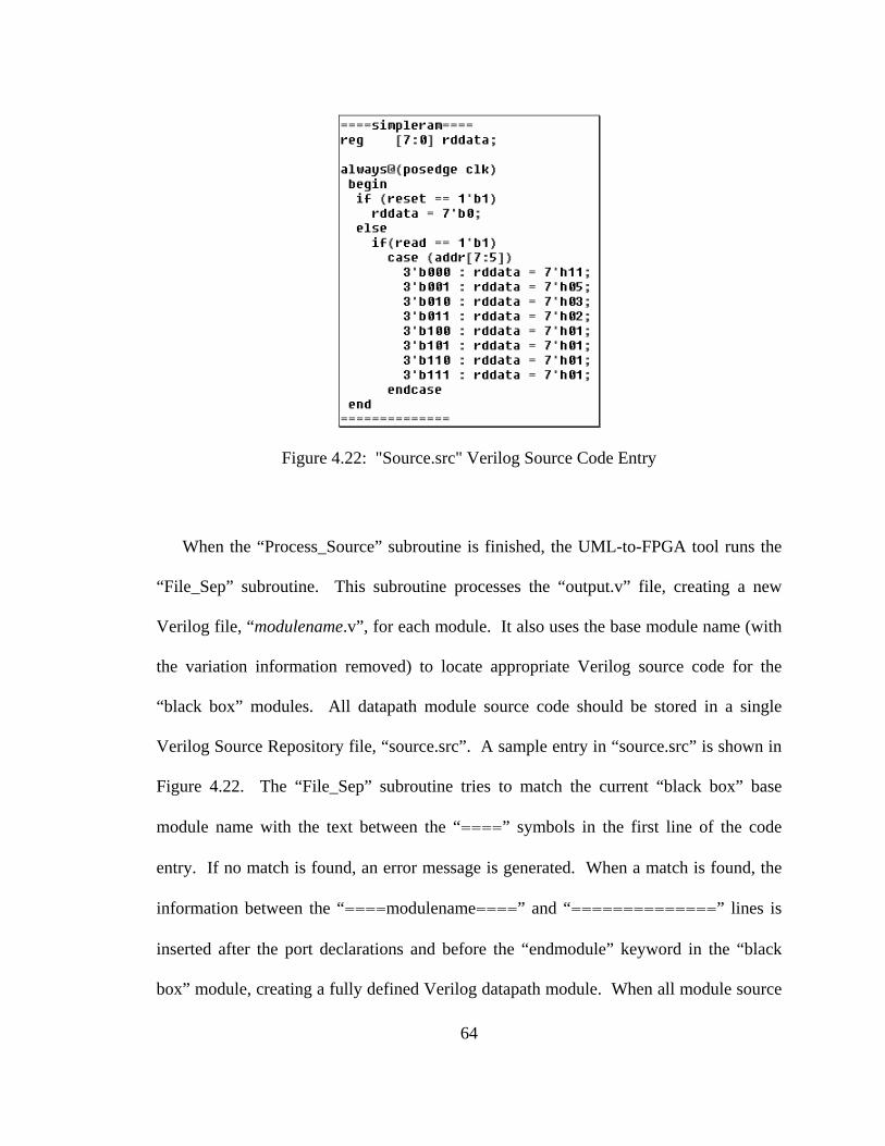
64
Figure 4.22: "Source.src" Verilog Source Code Entry
When the “Process_Source” subroutine is finished, the UML-to-FPGA tool runs the
“File_Sep” subroutine. This subroutine processes the “output.v” file, creating a new
Verilog file, “modulename.v”, for each module. It also uses the base module name (with
the variation information removed) to locate appropriate Verilog source code for the
“black box” modules. All datapath module source code should be stored in a single
Verilog Source Repository file, “source.src”. A sample entry in “source.src” is shown in
Figure 4.22. The “File_Sep” subroutine tries to match the current “black box” base
module name with the text between the “====” symbols in the first line of the code
entry. If no match is found, an error message is generated. When a match is found, the
information between the “====modulename====” and “==============” lines is
inserted after the port declarations and before the “endmodule” keyword in the “black
box” module, creating a fully defined Verilog datapath module. When all module source

65
code has been filled in and modules have been saved as individual source files, Stage 3 of
the UML-to-FPGA tool is complete.
As mentioned in previous sections, the UML-to-FPGA tool supports variable
buswidth declarations. Using special characters within “source.src”, the “File_Sep”
subroutine can be forced to fill in Verilog information based on port definitions in the
“black box” module it is currently processing. These “variable” parameters are indicated
in “source.src” with the text string “###define(widthtype):portname###”, where
widthtype defines the method for calculating the inserted value and portname indicates
which port of the current module should be used to retrieve the width information. If the
widthtype is “width”, then the buswidth value used in the port declaration is incremented
by one to indicate the true width of the port (i.e. the bus width “[6:0]” implies a 7-bit
port). If widthtype is “buswidth”, then the value found in the declaration for the given
port is used directly. The entire text string between and including the “###” end markers
is then replaced in the Verilog source code by the appropriate buswidth value.
4.4 Stage 4 – Logic Synthesis
Stage 4 of the of the UML-to-FPGA tool converts the Verilog HDL source code
created in Stage 3 to a netlist of synthesized logic elements. The logic synthesis process
can be invoked in three different ways, depending on which off-the-shelf vendor tool is
selected in the command to begin the UML-to-FPGA conversion process. The third
argument of the UML-to-FPGA command selects between the use of the Synplify Pro
synthesis tool (“-syn”) or the synthesis tool provided by the chosen programmable logic
66
vendor (“-ven”). Since the vendor-specific synthesis processes are integrated into the
design software for the programmable logic vendor of choice, details regarding the usage
of these synthesis tools will be incorporated into Section 4.5 of this document.
Therefore, this section will address the usage and invocation of logic synthesis using
Synplicity’s Synplify Pro tool.
The Synplify Pro tool is designed to be used primarily with its GUI, but it also
supports batch processes from the command line using the Tcl scripting language. To
use the command line interface, all the information needed for logic synthesis must be
included in a script file that defines parameters and execution guidelines for the Synplify
tool. The UML-to-FPGA Perl code automatically generates the file “modulename-
syn.tcl” for this purpose, where modulename is the name of the top-level design module
defined in Verilog HDL.
Included in “modulename-syn.tcl” are “set_option” arguments that define the
technology family, part number, package type, and speed grade for the programmable
logic device being targeted for the design, as well any necessary compilation parameters.
In the current implementation, programmable logic device information is hard-coded on a
per-vendor basis, since only one development board from each vendor was available for
lab development. In future versions of the UML-to-FPGA tool, this information would
ideally be selected in real-time by the user. Following the synthesis parameter directives,
the Verilog source code is added to the project by including an “add_file –verilog
sourcefile.v” directive to the Tcl script file for each source module in the design. By
convention, Synplify requires that the final “add_file” directive must be for the top-level

67
design file. Finally, the last line of the Tcl script file contains the text “project –run”,
which tells Synplify to end project creation and run its logic synthesis process.
After the Tcl script is created, the UML-to-FPGA tool executes the following
command: “synplify_pro -batch modulename-syn.tcl > synplify.txt”. This invokes the
Synplify tool and tells it to run in batch mode using the indicated file. All standard
output is directed to the file “synplify.txt” for later analysis if desired. Synplify generates
a large number of result files and reports during the synthesis process, but the UML-to-
FPGA tool preserves only two of these output files: the synthesis report file,
“modulename.srr”, and the synthesized netlist file. For the selected Xilinx device, the
generated file, “modulename.edf”, is in EDIF format. If an Altera device is the target, the
netlist file, “modulename.vqm”, is in VQM format. All other result files and directories
are removed. At this point in the process, if Synplify was chosen as the logic synthesis
tool, Stage 4 of the UML-to-FPGA conversion process is complete.
4.5 Stage 5 – Vendor-Specific Design Flow
The fifth and final stage of the UML-to-FPGA conversion process makes use of
vendor-specific design tools to correctly map, place, and connect logic elements on a
specific programmable device, known as the target. Most vendor design tools also
include a logic synthesis program, and this Stage 4 operation is supported as an option
selected by the user if the Synplify tool is not used. The final processing step takes the
completed “virtual” design created by the design software and converts it to a binary file
that is downloaded directly into the target device. The information contained in this

68
programming file tells the target device how to configure its internal programmable
elements to implement the design specified by the original UML model. The second
command-line argument of the UML-to-FPGA tool (“-a” or “-x”) specifies which
vendor’s target device is being used. Like Synplify, Altera Quartus-II and Xilinx ISE are
designed to be used with a GUI but also support command line batch-mode interfaces.
Design flow parameters, directives, and constraints must be defined by the UML-to-
FPGA tool before the Altera or Xilinx design flow is invoked. This section details the
requirements and usage of the vendor-specific batch-mode tools utilized by the UML-to-
FPGA tool.
4.5.1 Altera Design Flow
Altera Quartus-II batch mode is based on Tcl scripting, much like Synplify Pro. The
UML-to-FPGA Perl script must collect the necessary information to create a Tcl script
file, “modulename.tcl”, which governs design flow and parameters, where modulename is
the name of the top-level design module. The first line of the Quartus-II Tcl script file
contains the following text:
project_new -family "Cyclone II" -part EP2C35F672C6 -overwrite modulename
The “-family” and “-part” parameters have been hard coded for development, but the
purpose of this first statement is clear: to define the project name (equivalent to the name
of the top-level design module) and the target Altera device. The following line (or lines)

69
in the Tcl script file defines the source design file. When Synplify Pro is used for design
synthesis, the design file declaration is:
set_global_assignment -name VQM_FILE modulename.vqm
If Altera’s own vendor-specific synthesis tool is to be used, there must be a design
file declaration for each source Verilog file generated in Stage 3 of the UML-to-FPGA
tool in the format:
set_global_assignment -name VERILOG_FILE verilogmodule.v
One of the most important steps in programmable logic design is definition of design
constraints. Vendor design tools use these constraints as design goals to govern the
process of mapping, placing, and interconnecting logic components within the target
device. The most common design constraints define pin placement on the target device.
The top-level I/O ports in the overall design are mapped to physical I/O pins on the target
device, and in order for there to be connectivity with any external devices (e.g. switches,
LEDs, other ICs), the designer must assign signals to specific pins. If the target device
pinout is not defined, the placement tool will assign I/O pins arbitrarily, which can lead to
unpredictable results. Therefore, pinout constraints must be supplied as an input to the
vendor design flow. Other design constraints might include clock frequency design goals
and specific placement instructions for internal logic elements.
70
Design constraints for the Quartus-II tool can be defined using Tcl commands, so
pinout constraints are listed in the Tcl script file. The constraint assigning the port
“reset” to pin V2 of the target device might have the format:
set_location_assignment PIN_V2 -to reset
All pinout constraints for the Altera device, like the one shown above, are hard coded
into the file modulename.qsf. The UML-to-FPGA Perl script copies the contents of this
constraints file into the Tcl script file so that the constraints will be processed during
Quartus-II design flow.
The “set_global_assignment” directive is used to include any other design parameters
in the Tcl script file, and the final line of the script file is “project_close”. Once the Tcl
script file is created, Quartus-II design flow is initiated. The first command: “quartus_sh
-t modulename.tcl > ./quartus.tmp” creates the project environment for the design using
the information from the Tcl script. Any output to the screen is redirected to the
“quartus.tmp” file. The second command, “quartus_map modulename > ./quartus.tmp”,
invokes the Quartus-II mapping tool that integrates all constraints and design entities into
a single database file. The “quartus_map” tool will also invoke the Quartus-II Integrated
Synthesis tool if Verilog design files must be synthesized. The third command,
“quartus_fit modulename > ./quartus.tmp”, invokes the Quartus-II place-and-route tool
that performs all pin assignments, logic cell assignments, and logic cell interconnection
selection. The final command, “quartus_asm modulename > ./quartus.tmp”, invokes the

71
Quartus-II assembler tool that creates the binary programming image file
(“modulename.sof”) for the target device. Screen output for each of these commands is,
again, routed to the “quartus.tmp” file. Any design flow errors that occur will be listed in
this file. After each tool completes its function, “quartus.tmp” is checked by the UML-
to-FPGA tool. If any errors are detected in this file, the Perl script will report them and
stop execution of the conversion process. If all Quartus-II processes complete with no
errors, a valid programming image file will have been created, and the design conversion
will be complete.
4.5.2 Xilinx Design Flow
Xilinx ISE command-line design flow is slightly different from that of Altera.
Instead of using Tcl scripting, Xilinx has defined its own proprietary batch-mode design
flow, known as XFLOW. XFLOW uses its own script, or “flow”, files to govern the
invocation of the various tools that comprise its design flow. The script file, “fpga.flw”,
is provided by Xilinx, but may be modified by the user to select which tools are used.
The Xilinx tools used in the design flow also have their own “options” files that dictate
their operational parameters. Xilinx provides these “options” files with default
parameters pre-defined. The files “xst_mixed.opt”, “balanced.opt”, and “bitgen.opt”
must be copied to the XFLOW working directory before the Xilinx design flow is
initiated.
72
When Synplify Pro is used as the logic synthesis tool, XFLOW can be invoked to
operate directly on the modulename.edf file produced in UML-to-FPGA Stage 4. The
command used to invoke XFLOW in such a case is:
xflow -p xc3s200ft256-5 -implement balanced.opt -config bitgen.opt
-wd WORK -rd ../OUTPUTS modulename.edf > ./xflowout.txt
The “–p” parameter defines the Xilinx target device; the “-implement” parameter
defines the option file to be used for the Xilinx “ngdbuild”, “map”, and “par” tools; the “-
config” parameter defines the option file used for the “bitgen” tool; and the “-wd” and “-
rd” parameters define input and output directories to be used during the XFLOW process.
The “ngdbuild” tool is used to build Xilinx-specific circuit descriptions using the netlist
provided by Synplify. Xilinx uses its “map” tool to map these descriptions to specific
Xilinx target device logic constructs, while the “par” tool performs all virtual placing and
routing functions. Finally, the “bitgen” tool is used to generate the binary programming
image file.
If the Synplify Pro tool is not selected by the user, then XFLOW requires a project
file that lists all the Verilog modules needed for logic synthesis. If the “-x” and “-ven”
options are selected, the UML-to-FPGA tool will create a file called “modulename.prj”
containing a line for each Verilog module with the format: “verilog WORK
verilogmodule.v”. In this case, XFLOW is invoked using the command:
73
xflow -p xc3s200ft256-5 -synth xst_mixed.opt -implement balanced.opt -config
bitgen.opt -wd WORK -rd ../OUTPUTS modulename.prj > ./xflowout.txt
Here, the additional “-synth” parameter is used to define the option file used for the
Xilinx synthesis tool, “xst”. The netlist created by “xst” is fed into the “ngdbuild” tool,
taking the place of the EDIF file used when the Synplify option is selected.
XFLOW screen output is always redirected to the file “xflowout.txt”. After XFLOW
stops running, the UML-to-FPGA tool checks this file for any listed errors. If any errors
exist, the Perl script will report them and stop execution of the conversion process.
Pinout constraints and other requirements are hard coded into the file
“modulename.ucf”, which must be copied into the XFLOW working directory before the
Xilinx design flow is initiated. Though it is a separate file, XFLOW incorporates it into
the design as long as modulename matches the name of the top-level design file. The
Xilinx constraint file format is shown below. In this example, the “reset” signal is
assigned to pin K13.
NET "reset" LOC = "K13";
If the XFLOW process completes with no errors, a valid programming image file,
“modulename.bit”, will have been created, and the UML-to-FPGA design conversion will
be complete.

74
4.5.3 Design Flow Clean-up
After the vendor-specific design flow process is completed and a valid binary
configuration file has been produced for the target programmable device, there are a large
number of extraneous files in the UML-to-FPGA working directory. Generated by the
vendor design tool, they are the various report files, parameter files, and intermediate
design files produced during the design flow process. The UML-to-FPGA Perl script
calls a subroutine that moves all essential design and report files to the “OUTPUTS”
directory and removes the remaining, unnecessary files. Included among the files
preserved in the “OUTPUTS” directory are the DAXML model file, the Verilog HDL
source files, the binary configuration file, any existing Tcl files, the Synplify Pro netlist
file (if applicable), and any vendor-generated log or report files. Once this clean-up
process is completed, the UML-to-FPGA tool exits, and returns the user to the command
prompt.

75
Chapter 5
TOOL EVALUATION
5.1 Running the UML-to-FPGA Tool
The UML-to-FPGA tool is invoked from a command line prompt using the following
syntax:
perl ./uml2fpga {-a|-x} {-syn|-ven} {toplevelmodule} {inputfile.xml}
All command arguments shown above are required. The first argument tells the tool
which vendor design flow to follow and must correspond to the vendor of the target
programmable device. Option “-a” selects Altera design flow, and option “-x” selects
Xilinx design flow. The second command argument specifies the tool that should be
used for logic synthesis. Option “-syn” indicates that Synplify Pro design flow should
be used. Option “-ven” specifies that the synthesis tool supplied by the selected
programmable logic vendor should be used. The third command argument specifies the
name of top level Verilog module for the design. This information is used to ensure that
the design module hierarchy is correctly interpreted by the UML-to-FPGA tool. The
final argument is the name of the input model file, in XMI format. This model file must

76
have an “.xml” extension. The figures below show some examples of on-screen feedback
provided during UML-to-FPGA tool operation.
Figure 5.1: Sample UML-to-FPGA Screen Output
5.2 Testing Methodology
In order to test the automation functionality of the UML-to-FPGA tool, two sample
designs were created in UML, following the design capture conventions specified in
Sections 4.1.1 and 4.1.2. The completed high-level UML models were processed using
the UML-to-FPGA tool and tested on available FPGA design development hardware.
Though the UML-to-FPGA tool has been tested successfully on Xilinx development
77
hardware, the most recent testing has been completed using the Altera DE2 development
board, which contains a Cyclone II family FPGA supporting over 33,000 programmable
logic elements.
The first of the two sample designs was a simple traffic light system implementation,
initially intended to test Verilog code generation for the controller module alone. Initial
testing was done by integrating the automatically generated Verilog code for the traffic
light controller module with a set of hard coded datapath elements in order to synthesize
a complete design for hardware testing. Once a functional traffic light system
implementation was achieved using controller-only model transformation, development
of automatic datapath module generation began. The simple datapath elements used in
the traffic light system model were ideal for the early stages of development and
debugging. Upon successfully realizing a working hardware implementation with HDL
generated automatically from both controller and datapath UML models, the second,
more complex, sample design was introduced.
Designed to create a more extensive verification environment for the UML-to-FPGA
tool, the second sample design was an implementation of an 8-bit iterative Newton-
Raphson inverter. This design primarily tested the automatic datapath module generation
features of the UML-to-FPGA tool by incorporating greater numbers of modules,
multiple copies of modules, and multiple versions of similar modules. The
aforementioned elements of complexity proved to be critical test cases that contributed
greatly to the development of a robust design.
78
The sample designs were tested using both logic synthesis options supported by the
UML-to-FPGA tool. Configuration image files generated by the tool were downloaded
into the target FPGA, and design verification against the originally specified UML model
was carried out manually using the various I/O buttons and switches provided on the
hardware development board.
5.3 Design Results
In addition to the physical hardware realization of the designs captured in UML,
which must be demonstrated using the FPGA development board, the UML-to-FPGA
tool captures and preserves a variety of output data and report files in a results directory
named “OUTPUTS”. Table 5.1 and Table 5.2 list and describe the typical contents of
this directory resulting from Altera-specific design flow using the Quartus Integrated
Synthesis tool and Synplify Pro logic synthesis, respectively.

79
Table 5.1: UML-to-FPGA Output Files using Altera-specific Synthesis
Output File Description toplevel.fit.eqn Proprietary equations generated by the Quartus Fitter tool toplevel.map.eqn Proprietary equations generated by the Quartus Mapper tool toplevel.pin Table of design pinout assignments on the target device toplevel.pof Binary configuration image file (parallel download) toplevel.asm.rpt Quartus Assembler report file toplevel.fit.rpt Quartus Fitter report file toplevel.flow.rpt Quartus design flow report file toplevel.map.rpt Quartus Analysis and Synthesis report file toplevel.tan.rpt Quartus Timing Analyzer report file toplevel.sof Binary configuration image file (serial download) toplevel.fit.summary Summary of Quartus Fitter results toplevel.map.summary Summary of Quartus Synthesis results toplevel.tan.summary Summary of Quartus Timing Analyzer results toplevel.tcl Quartus Tcl script file toplevel.v, *.v Verilog HDL source modules DAXML.xml DAXML model file
Table 5.2: UML-to-FPGA Output Files using Synplify Pro Synthesis
Output File Description toplevel.fit.eqn Proprietary equations generated by the Quartus Fitter tool toplevel.map.eqn Proprietary equations generated by the Quartus Mapper tool toplevel.pin Table of design pinout assignments on the target device toplevel.pof Binary configuration image file (parallel download) toplevel.asm.rpt Quartus Assembler report file toplevel.fit.rpt Quartus Fitter report file toplevel.flow.rpt Quartus design flow report file toplevel.map.rpt Quartus Analysis and Synthesis report file toplevel.tan.rpt Quartus Timing Analyzer report file toplevel.sof Binary configuration image file (serial download) toplevel.srr Synplify Pro log file toplevel.fit.summary Summary of Quartus Fitter results toplevel.map.summary Summary of Quartus Synthesis results toplevel.tan.summary Summary of Quartus Timing Analyzer results toplevel.tcl Quartus Tcl script file toplevel-syn.tcl Synplify Pro Tcl script file synplify.txt Synplify Pro run-time output log toplevel.v, *.v Verilog HDL source modules toplevel.vqm Synplify-generated netlist file DAXML.xml DAXML model file

80
Report and log files generated by the design tools typically include a listing of
important output parameters related to the function provided, as well as the input
parameters and settings used for the most recent implementation and a copy of all screen
output generated during run-time. This report information generated by the synthesis and
implementation tools can be extremely valuable for design debugging and analysis,
especially in cases for which design hardware is not yet available. The following set of
tables is derived entirely from information contained within the report and summary files
generated by Altera’s Quartus-II design toolset.
Table 5.3: Comparison of Automated and Manual Implementation Methods
Parameter Automated Manual Total Logic Elements Used 110 76 4-input LUTs (look up tables) used 39 30 3-input LUTs used 20 17 <3-input LUTs used 41 29 Registers Used 57 27 Average signal fanout 2.54 2.51 Worst-case Register-Register Delay 4.944 ns 10.748 ns Maximum Clock Frequency 202.27 MHz 93.04 MHz
Table 5.3 compares the implementation results, in terms of internal FPGA resource
usage and timing performance estimates, for two implementations of the sample Newton-
Raphson inverter design. Here, the comparison is between results generated by the
UML-to-FPGA tool and results generated using a low-level, non-automated design
approach. In both cases, the Quartus-II Integrated Synthesis tool was used. The non-

81
automated inverter implementation was designed using a combination of Verilog HDL
and schematic capture, using tools provided by Altera’s design software. It should be
noted that this “manual” approach was developed for an independent project and was
implemented long before the UML-to-FPGA tool was conceived. While the internal
structures of the two implementations naturally differ, their external interfaces and
functionality are identical. Consequently, a true comparison of design methodologies can
be made. Differences in the number of internal resources used in the two
implementations can be primarily attributed to the controller design. Where the UML-to-
FPGA tool is currently limited to a Moore machine controller implementation, the low-
level design takes advantage of the flexible nature of Verilog design constructs to
generate a more compact implementation with fewer logic elements. This difference in
implementation methodology might also explain the timing performance advantage held
by the automated implementation. By using more area (in the form of register elements),
the UML-to-FPGA implementation requires less delay between sequential elements,
thereby decreasing the minimum possible clock period and increasing the maximum
operational frequency of the circuit. Additionally, this performance advantage is
evidence that the use of a high-level, automated design methodology does not necessarily
limit or reduce the quality of the implemented design.
Table 5.4 shows a comparison of internal FPGA resource usage when different
synthesis tools are used for the implementation of the sample traffic light system design.
A designer could use the generated information to determine which synthesis method

82
allows for a more efficient usage of hardware resources. In the example shown below, it
appears that the second option would be the preferred logic synthesis method.
Table 5.4: Comparison of Synthesis Tools using Logic Mapping Parameters
Parameter Tool #1 Tool #2 Registers Used 41 41 Combinational Functions Implemented 143 134 4-input LUTs used 86 60 3-input LUTs used 12 49 <3-input LUTs used 45 25 Average signal fanout 2.76 2.85 Logic Cells Used 184 175
Table 5.5 shows a comparison of internal FPGA resource usage based on outputs
from the Quartus-II Fitter tool for the sample Newton-Raphson inverter design. Here
design comparisons are made between two different Verilog datapath module source
libraries, one of which uses Altera’s Library of Parameterized Modules (LPMs) instead
of standard Verilog coding. Once again, a designer can glean important design trade-off
information from the output files preserved by the UML-to-FPGA tool. Here, it is clear
that using a Verilog source code library that utilizes LPMs will lead to a much more
efficient use of hardware resources.
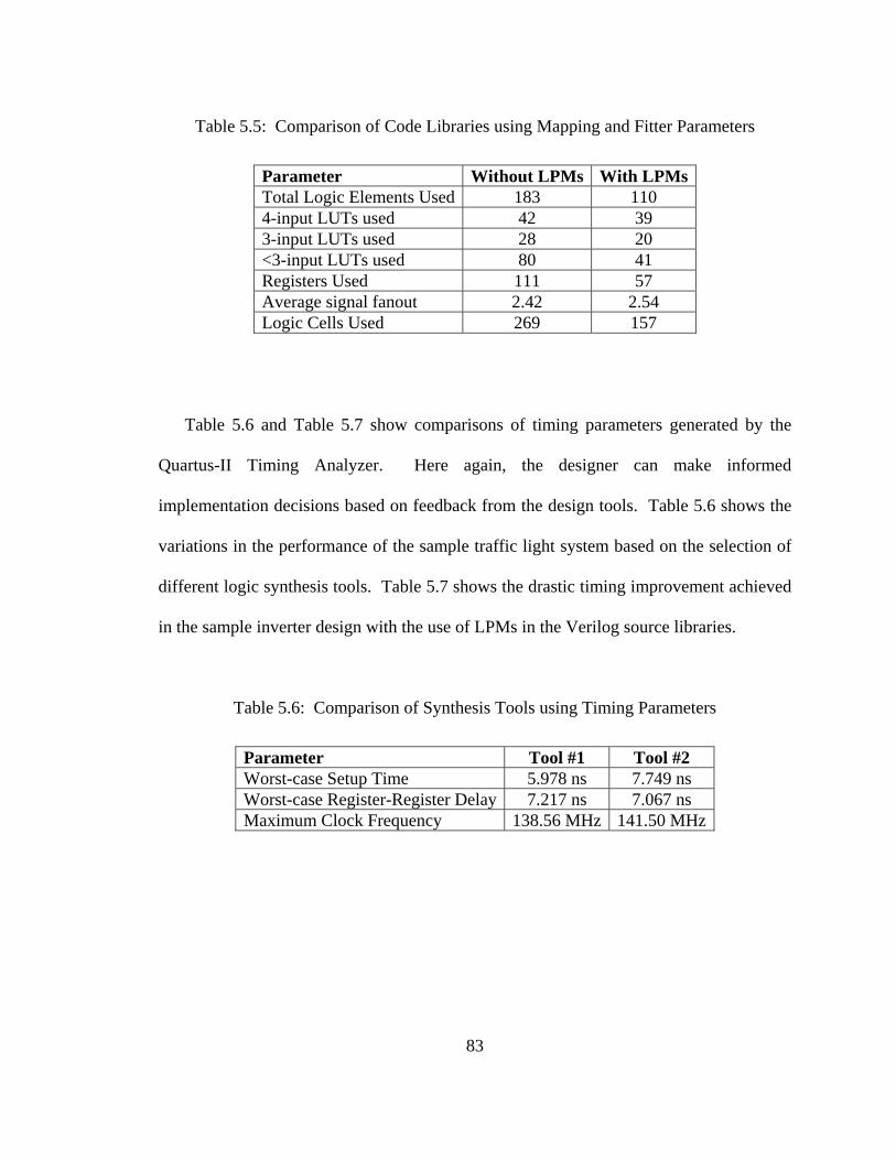
83
Table 5.5: Comparison of Code Libraries using Mapping and Fitter Parameters
Parameter Without LPMs With LPMs Total Logic Elements Used 183 110 4-input LUTs used 42 39 3-input LUTs used 28 20 <3-input LUTs used 80 41 Registers Used 111 57 Average signal fanout 2.42 2.54 Logic Cells Used 269 157
Table 5.6 and Table 5.7 show comparisons of timing parameters generated by the
Quartus-II Timing Analyzer. Here again, the designer can make informed
implementation decisions based on feedback from the design tools. Table 5.6 shows the
variations in the performance of the sample traffic light system based on the selection of
different logic synthesis tools. Table 5.7 shows the drastic timing improvement achieved
in the sample inverter design with the use of LPMs in the Verilog source libraries.
Table 5.6: Comparison of Synthesis Tools using Timing Parameters
Parameter Tool #1 Tool #2 Worst-case Setup Time 5.978 ns 7.749 ns Worst-case Register-Register Delay 7.217 ns 7.067 ns Maximum Clock Frequency 138.56 MHz 141.50 MHz

84
Table 5.7: Comparison of Code Libraries using Timing Parameters
Parameter Without LPMs With LPMs Worst-case Setup Time 6.395 ns 5.618 ns Worst-case Register-Register Delay 9.794 ns 4.944 ns Maximum Clock Frequency 102.10 MHz 202.27 MHz
It should be noted that all information provided by design synthesis tools could be fed
back into and processed by an automated tool like UML-to-FPGA in order to provide a
more “intelligent” automated design tool that incorporates these implementation results
and makes informed design decisions based on requirements set forth in the high-level
system model.
85
Chapter 6
CONCLUSIONS AND IDEAS FOR FUTURE RESEARCH
6.1 Future UML-to-FPGA Tool Development
The UML-to-FPGA implementation presented in this Thesis is intended to be a
“proof-of-concept” design. Ideally, this automated hardware generation process would
be integrated into a larger design package used in an MDA development environment,
where a system designer could define high-level models and be able to realize them in
hardware, software, or a combination of both, with only a minimal amount of knowledge
about the lower-level implementation mechanisms. However, there are many additional
features and improvements that can be made to the UML-to-FPGA tool as a stand-alone
hardware design tool before it is integrated into an all-encompassing MDA system design
tool. The remainder of this section will discuss several useful features that could be the
focal point of the UML-to-FPGA tool development effort in the near future.
6.1.1 Multiple XMI Format Support
As mentioned in Section 4.1.3, UML design packages supporting XMI export
functionality would not necessarily generate identical XML documents from the same
UML model. As a stand-alone conversion tool that accepts an XMI document as input, it
would be advantageous, in terms of portability and utility, for UML-to-FPGA to support

86
UML design capture from as many off-the-shelf development packages as possible.
Until the design is integrated into a design tool of larger scope, it remains useful to retain
flexibility in terms of the third-party tools with which it can interface.
Support for multiple XMI formats can be implemented simply by revising the Stage 2
XSLT transform used by UML-to-FPGA. This can be done without the tool itself ever
having to know what software generated the XMI it is processing. By using multiple
pattern-matching templates corresponding to the unique XMI paths generated by the
various UML design tools, multiple XMI formats can be supported within a single XSLT
rules file. The development effort would be focused on investigating the similarities and
differences between XMI formats and mirroring the existing XSLT guidelines so that the
same DAXML output is achieved.
6.1.2 Automatic Constraint File Generation
The UML-to-FPGA tool already processes design constraints at a certain level via the
implementation of DATARANGE elements, as described in Section 4.1. However, this
feature can be expanded to cover a wider range of design functionality. UML provides
means for capturing the entire spectrum of design requirements, all of which will be
included in the XMI document that is exported and used as input for the UML-to-FPGA
tool. Taking advantage of the power of XSLT to generate any type of formatted text, the
conversion process can be utilized to generate any constraints or implementation files
required in later stages of the tool, in addition to the Verilog HDL code that is already
being created.

87
Of particular importance in hardware design are the cost and performance of the
design. Specifications for the “cost” of a design using configurable logic typically refer
to the number of programmable resources utilized by the implemented design. Design
requirements captured in UML might specify maximum cost by defining the particular
target device into which the design must fit, or by defining a maximum number of
programmable logic cells to be used within the target device. Additionally, the I/O
pinout for the target device might already be defined. Specifications for design
“performance” might dictate a specific clock frequency at which the design must operate.
Such timing requirements, together with logic element and pinout constraints, impact the
way the external synthesis and design realization tools produce the final implementation.
If these specifications can be defined in some manner at the system level, functions
within the UML-to-FPGA tool can be defined to convert these requirements into
information that can be processed by the necessary low-level design tools, thereby adding
a further degree of automation to the entire application.
In the current implementation, most of the design constraint parameters have been
hard-coded into the UML-to-FPGA tool because the design was limited to only two
possible target devices. Ideally, information describing parameters such as target device
information, I/O pin assignments, minimum required clock frequency, and other vendor-
specific design flow options would be incorporated into the requirements specified in the
UML model at some point in the design cycle. Again, implementation of this feature
would necessitate adaptation of existing XSLT rules files. Modifications to the DAXML
schema to support requirement specifications would also be beneficial.
88
Thought must also be put into determining how, and at what level and/or design
phase, these requirements will be integrated into the UML design model. Once the early
stages of the UML-to-FPGA tool can generate constraint rules and processing
instructions that can be used by later stages in the conversion process, additional, more
powerful functionality may be implemented, as is explained in the following section.
6.1.3 Iterative Requirement Satisfaction
Once design synthesis parameter and constraint generation has been incorporated into
the UML-to-FPGA tool, it would be possible for the tool to incorporate feedback from
the various synthesis packages used in the conversion process to ensure that design goals,
as defined within the UML model, are met. An Iterative Requirement Satisfaction (IRS)
feature would allow multiple passes through, at a minimum, Stages 4 and 5 of the UML-
to-FPGA process, with the tool taking a slightly different implementation approach with
each iteration. The UML-to-FPGA tool can use the various report files generated by the
logic synthesis and design realization tools to determine if design goals such as circuit
performance and design cost have been met.
For example, a vendor design tool might report that the given design does not fit
within the specified target device, telling the UML-to-FPGA tool that it has not met its
area constraint. Additionally, most programmable logic vendors incorporate a timing
analysis package into their tool that is designed for modeling the delay through and
between programmable logic elements within their devices. By collecting information
from a vendor’s timing analysis report, the UML-to-FPGA tool can verify that the clock
89
delays within the specified target device meet the performance requirements set by the
system designer. Some tools now incorporate power dissipation calculators, which also
might be used to generate feedback for an automated iterative design process.
Much of the design work for an IRS feature would go into defining algorithms and/or
heuristics for processing design tool feedback and altering design parameters. Vendor
tools generally have goal-oriented synthesis processes that incorporate certain
requirements to define design implementation. However, even these processes are not
100% effective. The UML-to-FPGA tool must define methods for adjusting synthesis
parameters at each iteration, so that the external tools are given an increased amount of
flexibility.
In addition to manipulating external tool parameters, other applications might be
employed to modify the design model itself. One example might be a tool extension that
automatically pipelines design datapath elements to reduce delay between clocked
elements [30], under the assumption that a new pipeline stage would be added upon each
iteration until timing constraints are met or area constraints are exceeded. Additional
research would be necessary to determine at what point such methods would be more
efficient than simply adjusting synthesis parameters.
6.1.4 Design Checking
In the current incarnation of the UML-to-FPGA tool, there are few true design
checkpoints. The tool will exit if an XSLT conversion fails, or if one of the Stage 4 or
Stage 5 synthesis processes encounters an error, but beyond these points of failure, the

90
tool does little in terms of verification. For example, errors in UML capture might not be
detected until the synthesis tool detects faulty Verilog code several stages later. Further
steps should be taken to allow design checks to be as localized within the conversion
process as possible.
If they cannot be checked within the UML tool itself, design capture conventions
could be checked in the XMI model or, perhaps even more easily, in the DAXML model.
Critical checks here would include verifying that the datapath elements are defined
correctly, that ports and components are named so that they correspond to the appropriate
source Verilog modules, that buswidths for ports and their corresponding nets match, and
that the controller ports identified in the datapath diagram correspond to those defined in
the controller diagram.
The XML files generated in Stages 1 and 2 of the conversion process may also be
checked for structural correctness using a schema validation tool. Many such tools are
available online or as part of XML development software. Schema validation would
ensure that proper formatting is observed in the XMI and DAXML models, so that poorly
formed XML does not impact downstream processing.
The tools invoked in Stages 4 and 5 of the UML-to-FPGA conversion process will
provide feedback to the designer if the original UML model does not produce
synthesizable Verilog HDL. However, additional tools may be incorporated to verify the
correctness of the source code that is produced. The SMU Hardware/Software Co-
Design team already has made efforts toward the development of a design validation tool
using SystemVerilog assertions [23].
91
6.1.5 SysML
Until this point, only the constructs defined by the UML standard have been
considered for use as the building blocks for modeling a hardware design. However,
UML’s roots as a software development tool tend to make the description of a hardware
system somewhat cumbersome, as is especially evident in the design capture conventions
and processing steps required for datapath specification. In particular, the UML
“Component” and “Dependency” constructs are each used in multiple contexts in the
UML component diagram, requiring unique text descriptors that add extra complexity to
the design capture and design conversion processes. For instance, UML “Component”
elements are used to represent both a datapath module and its individual input and output
ports, so the designer is required to manually establish the relationship between the two
types using specific naming syntax. Additional work is also required to process the XMI
model derived from UML because the translation tool must determine if each
“Component” element it finds in the XMI model structure represents a module or a port
before it can appropriately process the information. It is evident that, while UML does
provide a method for modeling hardware designs, it may not be the best possible solution.
OMG Systems Modeling Language, or SysML, provides the tools and structures
needed for a more elegant solution to hardware datapath capture. Adopted as a standard
in 2006, SysML has its roots in UML, but provides additional constructs and diagrams
that are specifically designed to describe physical system composition and
interconnection [16]. Direct support for module interconnection constructs would greatly
aid in datapath design capture and processing required when using the UML-to-FPGA

92
tool. Like its UML precursor, SysML also supports behavioral modeling and constraints
capture [29], which are necessary for detailing controller operation and defining system
requirements in the UML-to-FPGA tool. With these structural and behavioral constructs
designed specifically for modeling real-world systems, SysML is an ideal tool for
hardware/software co-design in a model-driven design environment.
Overall design parameters and packages are managed using SysML “Model
Elements”, which can be used to specify packageable elements and the relationships
between them [29]. This becomes especially useful when making implementation
decisions (choosing between a hardware or software solution) at the system design level.
Both hardware and software implementations can be modeled separately, and associated
with constraints elements that define overall design requirements [29], as shown in
Figure 6.1. Coupled with design realization tools like UML-to-FPGA, this process would
allow design decisions to be made at a high-level based on the success or failure of a low-
level design to meet certain system requirements.
Figure 6.1: SysML Model Elements

93
SysML “Block” constructs are the basic structural units that would replace UML
“Components” as the representation for the various modules within the datapath
description of a hardware system. SysML supports two forms of diagrams that can be
used for capturing the functional, behavioral, and structural elements of a design module.
The Block Definition Diagram helps to define the features and functions of a SysML
“Block”, while the Internal Block Diagram is used to capture the structure and
interconnections between design “Blocks” [29].
The most beneficial new construct supported by SysML, in terms of hardware
datapath design, may be the “Port”. A SysML “Port” defines a point of interaction
between a “Block” and its external environment. By interconnecting the “Ports” for each
“Block” in a datapath model, the complete structure of the design can be defined. It is
also important to note that “Ports” are automatically, and clearly associated, with a
particular design “Block”, removing the need for manual association by the designer [29].
Figure 6.2: SysML "Blocks", "FlowPorts", and "ItemFlows"
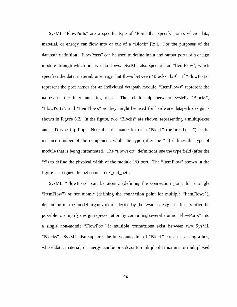
94
SysML “FlowPorts” are a specific type of “Port” that specify points where data,
material, or energy can flow into or out of a “Block” [29]. For the purposes of the
datapath definition, “FlowPorts” can be used to define input and output ports of a design
module through which binary data flows. SysML also specifies an “ItemFlow”, which
specifies the data, material, or energy that flows between “Blocks” [29]. If “FlowPorts”
represent the port names for an individual datapath module, “ItemFlows” represent the
names of the interconnecting nets. The relationship between SysML “Blocks”,
“FlowPorts”, and “ItemFlows” as they might be used for hardware datapath design is
shown in Figure 6.2. In the figure, two “Blocks” are shown, representing a multiplexer
and a D-type flip-flop. Note that the name for each “Block” (before the “:”) is the
instance number of the component, while the type (after the “:”) defines the type of
module that is being instantiated. The “FlowPort” definitions use the type field (after the
“:”) to define the physical width of the module I/O port. The “ItemFlow” shown in the
figure is assigned the net name “mux_out_net”.
SysML “FlowPorts” can be atomic (defining the connection point for a single
“ItemFlow”) or non-atomic (defining the connection point for multiple “ItemFlows”),
depending on the model organization selected by the system designer. It may often be
possible to simplify design representation by combining several atomic “FlowPorts” into
a single non-atomic “FlowPort” if multiple connections exist between two SysML
“Blocks”. SysML also supports the interconnection of “Block” constructs using a bus,
where data, material, or energy can be broadcast to multiple destinations or multiplexed
95
over a common structural connection [29]. Similar structures would be extremely
difficult to implement using UML.
In addition to supporting a greatly simplified datapath design capture methodology,
SysML also provides a highly defined set of constructs for capturing design
requirements. SysML “Constraint” blocks allow for the integration of engineering
analysis in the form of performance and reliability models. “Constraints” can specify
mathematical expressions or simple definitions that can be associated with a particular
“Block” within the design [29]. For example, a requirement limiting the delay through a
particular datapath block might be accomplished using a “Constraint” block bound
directly to the module “Block”. Other global constraints might be associated with the
entire hardware “Model Element”. Like UML, SysML supports system behavioral
modeling through State Machine descriptions [29]. Controller design capture
conventions would most likely remain the same, despite using SysML instead of UML.
Unfortunately, at the time of this tool implementation, no SysML design package was
available for use in design capture. However, as such tools become readily available,
effort should be made to convert the existing UML-to-FPGA tool to a SysML-to-FPGA
tool. Most of the design constructs defined in SysML, and described in the previous
paragraphs, can be intuitively mapped to the capture conventions defined for UML in
Chapter 4 of this document, making the transition of datapath and controller design
capture capability fairly simple. However, it is critical that the SysML design tool that is
selected be able to support some form of export functionality that can generate an XML-
based text file. The majority of the design work necessary to replace UML with SysML

96
in this tool will likely involve modifications to the Stage 2 XSLT rules that adapt the
conversion process to the organizational improvements provided by the new SysML
constructs.
6.2 Summary
Among the most difficult challenges facing today’s embedded system designers is the
task of dividing functionality implementation between hardware and software.
Technological advances, especially in programmable hardware technologies such as
FPGAs and CPLDs, are making it harder to draw a distinct line between the between the
two fields. Old design methodologies no longer yield optimal results and often lead to
difficulties in design verification and documentation, as well as poor design flow.
The Model Driven Architecture approach to hardware-software co-design offers the
designer a new method of system development. Using high-level abstractions to describe
system requirements, structure, and behavior, the MDA design approach allows the
designer to maintain a unified, implementation-independent model throughout most of
the development cycle. Implementation choices need only be made once a design and its
requirements have been fully defined, allowing for a more intelligent and informed
decision, and, typically, a more optimally realized design. The MDA approach to system
design is also intended to bridge the gap between system definition and system
implementation by allowing for automated coding and other intelligent design tools.
Though many such intelligent automation tools exist for software implementations, a
method for automated hardware implementation has yet to be fully developed.
97
This Thesis has attempted to rectify this discrepancy by proposing a framework for an
automated MDA-based hardware realization process that creates a fully functional
hardware realization from a high-level system model with a single command. As a
“proof-of-concept”, this document presented UML-to-FPGA, a functional automated
hardware implementation tool that utilizes off-the-shelf design software and commonly-
used scripting languages to generate working FPGA configuration images from UML
system models. Chapter 3 discussed the high-level architectural features of this five-
stage conversion process and presented justification for the design tools selected for its
implementation. Chapter 4 presented stage-by-stage design details for the UML-to-
FPGA tool, including discussion of UML design capture conventions, XML-based
intermediate design modeling formats, and implementation and/or invocation of the
processes needed for automatic Verilog HDL generation and programmable logic
synthesis. Chapter 5 followed by reporting experimental results from two sample designs
realized using the UML-to-FPGA tool. Finally, several feature improvements were
proposed for the future development of the current incarnation of the tool.
This Thesis also presented a new XML schema adapted from W3C’s State Chart
XML. Design Automation XML (DAXML) supports a structured format for the storage
of information and requirements related to both the controller and the datapath portions
of a synchronous sequential circuit, enabling all essential design parameters for a
complete hardware implementation to be captured within a single XML document. As
such, DAXML is provided as an intermediary hardware design model used for the
facilitation and simplification of automatic non-language-specific HDL code generation.

98
The UML-to-FPGA tool, including its associated third-party implementation
packages and its specific implementation procedures, presented in this Thesis is intended
to serve merely as a guideline for future MDA-based hardware implementation
applications. The individual translation and synthesis tools selected for this
implementation are commercially available off-the-shelf packages that can be
interchanged with other off-the-shelf or custom tools without impacting the overall
purpose of the design. The overall automation process does not depend on the use of
UML as a modeling tool, nor does it necessitate either design description with Verilog
HDL or the targeting of a specific hardware implementation technology. UML-to-FPGA
is just one possible implementation of a more general “MDA-to-FPGA” or, more
appropriately, “MDA-to-Hardware” framework.
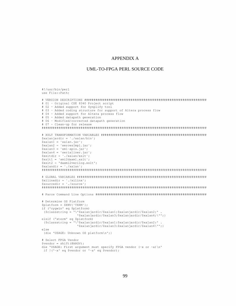
99
APPENDIX A
UML-TO-FPGA PERL SOURCE CODE
#!/usr/bin/perl use File::Path; # VERSION DESCRIPTIONS ################################################################## # 01 - Original CSE 8340 Project script # 02 - Added support for Synplify tool # 03 - Added coding structure for support of Altera process flow # 04 - Added support for Altera process flow # 05 - Added datapath generation # 06 - Modified/corrected datapath generation # 07 - Clean-up for release ######################################################################################### # XSLT TRANSFORMATION VARIABLES ######################################################### $xalanjardir = './xalan/bin'; $xalan1 = 'xalan.jar'; $xalan2 = 'xercesImpl.jar'; $xalan3 = 'xml-apis.jar'; $xalan4 = 'serializer.jar'; $xsltdir = './xalan/xslt'; $xslt1 = 'xmi2daxml.xslt'; $xslt2 = "daxml2verilog.xslt"; $xalandir = './xalan'; ######################################################################################### # GLOBAL VARIABLES ###################################################################### $xilinxdir = './xilinx'; $sourcedir = './source'; ######################################################################################### # Parce Command Line Options ############################################################ # Determine OS Platform $platform = $ENV{'TERM'}; if ("cygwin" eq $platform) {$classstring = "\"$xalanjardir/$xalan1;$xalanjardir/$xalan2;" . "$xalanjardir/$xalan3;$xalanjardir/$xalan4;\"";} elsif ("xterm" eq $platform) {$classstring = "\"$xalanjardir/$xalan1:$xalanjardir/$xalan2:" . "$xalanjardir/$xalan3:$xalanjardir/$xalan4\"";} else {die "USAGE: Unknown OS platform\n";} # Select FPGA Vendor $vendor = shift(@ARGV); die "USAGE: First argument must specify FPGA vendor (-x or -a)\n" if !("-x" eq $vendor or "-a" eq $vendor);

100
# Select Synthesis Tool $synopt = shift(@ARGV); die "USAGE: Second argument must specify synthesis method (-ven or -syn)\n" if !("-ven" eq $synopt or "-syn" eq $synopt); # Get Top Level module name $toplevel = shift(@ARGV); chomp($toplevel); die "ERROR: Top Level Source File does not exist\n" if !(-e "./$toplevel.xml"); # Get Input XMI File $inputfile = shift(@ARGV); chomp($inputfile); die "ERROR: XML Input File Does Not Exist...\n" if !(-e $inputfile); system "mkdir OUTPUTS"; # Perform XSLT Transformations ########################################################## &Transform; ######################################################################################### # Process Source File to Eliminate Duplicate Modules #################################### &Process_Source; ######################################################################################### # Separate Transform Output to Create Source Verilog #################################### &File_Sep; ######################################################################################### # Synthesize Verilog Code ############################################################### ######################################################################################### # Using Xilinx XFlow Synthesis ########################################################## if ("-ven" eq $synopt and "-x" eq $vendor) { #Create Xilinx project file for FPGA synthesis print "Creating Xilinx Project File\n"; @verilog_files = glob "WORK/*.v"; die "All verilog source files must be initially stored in $sourcedir\n" if (!defined(@verilog_files)); open TOPLEVELFILE, ">", "$toplevel.prj"; foreach $vfile (@verilog_files) { $vfile =~ s/WORK\///; print TOPLEVELFILE "verilog WORK $vfile\n"; } close TOPLEVELFILE; system "mv $toplevel.prj WORK"; #Run Xilinx XFlow print "Running Xilinx ISE XFlow\n"; system "xflow -p xc3s200ft256-5 " . "-synth xst_mixed.opt " . "-implement balanced.opt " . "-config bitgen.opt " . "-wd WORK " . "-rd ../OUTPUTS " . "$toplevel.prj " . " > ./xflowout.txt"; print "Generating FPGA Configuration File\n"; #Check for Xflow errors &Check_XFlow; }
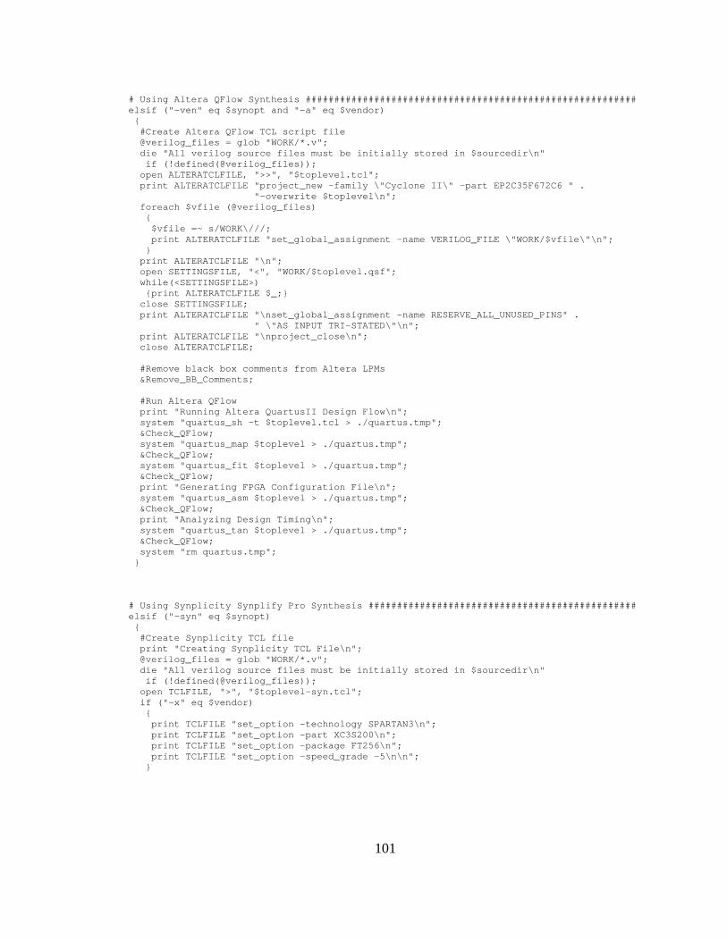
101
# Using Altera QFlow Synthesis ########################################################## elsif ("-ven" eq $synopt and "-a" eq $vendor) { #Create Altera QFlow TCL script file @verilog_files = glob "WORK/*.v"; die "All verilog source files must be initially stored in $sourcedir\n" if (!defined(@verilog_files)); open ALTERATCLFILE, ">>", "$toplevel.tcl"; print ALTERATCLFILE "project_new -family \"Cyclone II\" -part EP2C35F672C6 " . "-overwrite $toplevel\n"; foreach $vfile (@verilog_files) { $vfile =~ s/WORK\///; print ALTERATCLFILE "set_global_assignment -name VERILOG_FILE \"WORK/$vfile\"\n"; } print ALTERATCLFILE "\n"; open SETTINGSFILE, "<", "WORK/$toplevel.qsf"; while(<SETTINGSFILE>) {print ALTERATCLFILE $_;} close SETTINGSFILE; print ALTERATCLFILE "\nset_global_assignment -name RESERVE_ALL_UNUSED_PINS" . " \"AS INPUT TRI-STATED\"\n"; print ALTERATCLFILE "\nproject_close\n"; close ALTERATCLFILE; #Remove black box comments from Altera LPMs &Remove_BB_Comments; #Run Altera QFlow print "Running Altera QuartusII Design Flow\n"; system "quartus_sh -t $toplevel.tcl > ./quartus.tmp"; &Check_QFlow; system "quartus_map $toplevel > ./quartus.tmp"; &Check_QFlow; system "quartus_fit $toplevel > ./quartus.tmp"; &Check_QFlow; print "Generating FPGA Configuration File\n"; system "quartus_asm $toplevel > ./quartus.tmp"; &Check_QFlow; print "Analyzing Design Timing\n"; system "quartus_tan $toplevel > ./quartus.tmp"; &Check_QFlow; system "rm quartus.tmp"; } # Using Synplicity Synplify Pro Synthesis ############################################### elsif ("-syn" eq $synopt) { #Create Synplicity TCL file print "Creating Synplicity TCL File\n"; @verilog_files = glob "WORK/*.v"; die "All verilog source files must be initially stored in $sourcedir\n" if (!defined(@verilog_files)); open TCLFILE, ">", "$toplevel-syn.tcl"; if ("-x" eq $vendor) { print TCLFILE "set_option -technology SPARTAN3\n"; print TCLFILE "set_option -part XC3S200\n"; print TCLFILE "set_option -package FT256\n"; print TCLFILE "set_option -speed_grade -5\n\n"; }

102
if("-a" eq $vendor) { print TCLFILE "set_option -technology CYCLONEII\n"; print TCLFILE "set_option -part EP2C35\n"; print TCLFILE "set_option -package FC672\n"; print TCLFILE "set_option -speed_grade -6\n\n"; } print TCLFILE "set_option -fixgatedclocks 3\n\n"; foreach $vfile (@verilog_files) { if ("WORK/$toplevel.v" ne $vfile) { print TCLFILE "add_file -verilog \"$vfile\"\n"; } } print TCLFILE "add_file -verilog \"WORK/$toplevel.v\"\n"; print TCLFILE "\nproject -run"; close TOPLEVELFILE; #Run Syplify Pro synthesis tool print "Running Synplify Pro\n"; system "synplify_pro -batch $toplevel-syn.tcl > synplify.txt"; &Check_Synplify; if ("-x" eq $vendor) {system "mv rev_1/$toplevel.edf WORK";} if ("-a" eq $vendor) {system "mv rev_1/$toplevel.vqm WORK";} system "mv rev_1/$toplevel.srr ."; system "rm -r rev_1"; system "rm stdout.log"; #Run Vendor tool for Design Mapping and Config File Generation if ("-x" eq $vendor) { #Run Xilinx XFlow print "Running Xilinx ISE XFlow\n"; system "xflow -p xc3s200ft256-5 " . "-implement balanced.opt " . "-config bitgen.opt " . "-wd WORK " . "-rd ../OUTPUTS " . "$toplevel.edf " . " > ./xflowout.txt"; print "Generating FPGA Configuration File\n"; #Check for Xflow errors &Check_XFlow; } if ("-a" eq $vendor) { #Create Altera QFlow TCL script file open ALTERATCLFILE, ">>", "$toplevel.tcl"; print ALTERATCLFILE "project_new -family \"Cyclone II\" -part EP2C35F672C6 " . "-overwrite $toplevel\n"; print ALTERATCLFILE "set_global_assignment -name VQM_FILE \"WORK/$toplevel.vqm\"\n"; print ALTERATCLFILE "\n"; open SETTINGSFILE, "<", "WORK/$toplevel.qsf"; while(<SETTINGSFILE>) {print ALTERATCLFILE $_;} close SETTINGSFILE; print ALTERATCLFILE "\nset_global_assignment -name RESERVE_ALL_UNUSED_PINS" . " \"AS INPUT TRI-STATED\"\n"; print ALTERATCLFILE "\nproject_close\n"; close ALTERATCLFILE; #Remove black box comments from Altera LPMs &Remove_BB_Comments;
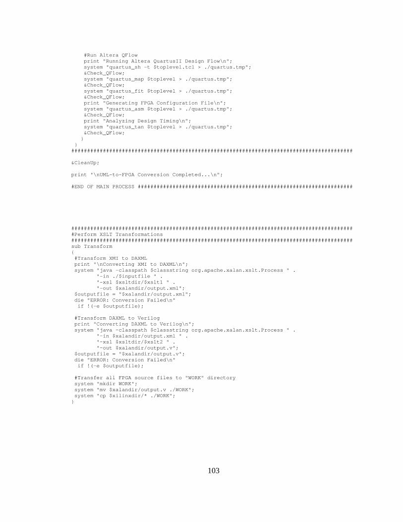
103
#Run Altera QFlow print "Running Altera QuartusII Design Flow\n"; system "quartus_sh -t $toplevel.tcl > ./quartus.tmp"; &Check_QFlow; system "quartus_map $toplevel > ./quartus.tmp"; &Check_QFlow; system "quartus_fit $toplevel > ./quartus.tmp"; &Check_QFlow; print "Generating FPGA Configuration File\n"; system "quartus_asm $toplevel > ./quartus.tmp"; &Check_QFlow; print "Analyzing Design Timing\n"; system "quartus_tan $toplevel > ./quartus.tmp"; &Check_QFlow; } } ######################################################################################### &CleanUp; print "\nUML-to-FPGA Conversion Completed...\n"; #END OF MAIN PROCESS #################################################################### ######################################################################################### #Perform XSLT Transformations ######################################################################################### sub Transform { #Transform XMI to DAXML print "\nConverting XMI to DAXML\n"; system "java -classpath $classstring org.apache.xalan.xslt.Process " . "-in ./$inputfile " . "-xsl $xsltdir/$xslt1 " . "-out $xalandir/output.xml"; $outputfile = "$xalandir/output.xml"; die "ERROR: Conversion Failed\n" if !(-e $outputfile); #Transform DAXML to Verilog print "Converting DAXML to Verilog\n"; system "java -classpath $classstring org.apache.xalan.xslt.Process " . "-in $xalandir/output.xml " . "-xsl $xsltdir/$xslt2 " . "-out $xalandir/output.v"; $outputfile = "$xalandir/output.v"; die "ERROR: Conversion Failed\n" if !(-e $outputfile); #Transfer all FPGA source files to "WORK" directory system "mkdir WORK"; system "mv $xalandir/output.v ./WORK"; system "cp $xilinxdir/* ./WORK"; }
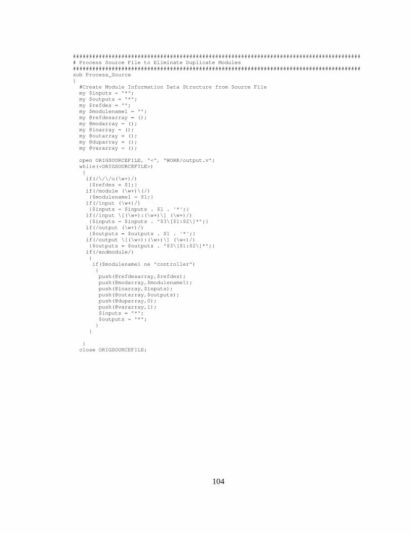
104
######################################################################################### # Process Source File to Eliminate Duplicate Modules ######################################################################################### sub Process_Source { #Create Module Information Data Structure from Source File my $inputs = "*"; my $outputs = "*"; my $refdes = ""; my $modulename1 = ""; my @refdesarray = (); my @modarray = (); my @inarray = (); my @outarray = (); my @duparray = (); my @vararray = (); open ORIGSOURCEFILE, "<", "WORK/output.v"; while(<ORIGSOURCEFILE>) { if(/\/\/u(\w+)/) {$refdes = $1;} if(/module (\w+)\(/) {$modulename1 = $1;} if(/input (\w+)/) {$inputs = $inputs . $1 . '*';} if(/input \[(\w+):(\w+)\] (\w+)/) {$inputs = $inputs . "$3\[$1:$2\]*";} if(/output (\w+)/) {$outputs = $outputs . $1 . '*';} if(/output \[(\w+):(\w+)\] (\w+)/) {$outputs = $outputs . "$3\[$1:$2\]*";} if(/endmodule/) { if($modulename1 ne "controller") { push(@refdesarray,$refdes); push(@modarray,$modulename1); push(@inarray,$inputs); push(@outarray,$outputs); push(@duparray,0); push(@vararray,1); $inputs = "*"; $outputs = "*"; } } } close ORIGSOURCEFILE;

105
#Analyze Module Information Data Structure for Dups/Mods my $i = 0; my $j = 0; foreach (@refdesarray) { if($_ ne "") { for($j=0;$j<$i;$j++) { #ignore duplicates if($duparray[$j] eq 0) { #match module name first if($modarray[$j] eq $modarray[$i]) { #if I/O ports match, it's a duplicate module if(($inarray[$j] eq $inarray[$i]) and ($outarray[$j] eq $outarray[$i])) {$duparray[$i] = 1;} #otherwise, create a new variation of the module else { $vararray[$i]++; if($vararray[$i] gt 2) { if($modarray[$i] =~ /(\w+)__(\d+)/) {$modarray[$i] = "$1__$vararray[$i]";} } else {$modarray[$i] = $modarray[$i] . "__$vararray[$i]";} } } } } } $i++; } #Update Source Verilog File my $numcomp = @refdesarray; my $intoplevel = 1; my $checking = 0; my $founddup = 0; my $savedindex = -1; open NEWSOURCEFILE, ">","WORK/newoutput.v"; open ORIGSOURCEFILE, "<", "WORK/output.v"; while(<ORIGSOURCEFILE>) { if($intoplevel) { if(/^(\w+) u(\d+)_/) { for($i=0;$i<$numcomp;$i++) { if($2 eq $refdesarray[$i]) {$savedindex = $i;} } if($vararray[$savedindex] ne 1) { s/(\w+) u(\d+)_(\w+) \(/$modarray[$savedindex] u$2_$modarray[$savedindex] \(/; } print NEWSOURCEFILE $_; } else {print NEWSOURCEFILE $_;} }

106
else { if($checking) { if($duparray[$savedindex] eq 0) { if(/module (\w+)\(/) {s/module (\w+)\(/module $modarray[$savedindex]\(/;} print NEWSOURCEFILE $_; } if(/======================================/) { $checking = 0; $savedindex=-1 } } else { if(/\/\/u(\d+)/) { $checking = 1; for($i=0;$i<$numcomp;$i++) { if($1 eq $refdesarray[$i]) {$savedindex = $i;} } } else {print NEWSOURCEFILE $_;} } } if(/======================================/) {$intoplevel = 0;} } close ORIGSOURCEFILE; close NEWSOURCEFILE; #die "debug now\n"; system "rm WORK/output.v"; rename "WORK/newoutput.v", "WORK/output.v"; } ######################################################################################### # Separate Transform Output to Create Source Verilog ######################################################################################### sub File_Sep { $fileseperror = 0; open XSLTOUTFILE, "<", "WORK/output.v"; while(<XSLTOUTFILE>) { open NEWSOURCEFILE, ">>", "$sourcedir/zzz.v"; if(/module\s(\w+)__(\d+)/) {$sourcemodulename = $1;} elsif(/module\s(\w+)/) {$sourcemodulename = $1;} if(/module\s(\w+)/) {$modulename = $1;}

107
if(/endmodule/) { if($sourcemodulename ne "controller" and $sourcemodulename ne $toplevel) { # search for source material open SRCCODEFILE, "<", "$sourcedir/source.src"; $found = 0; $copy = 0; while(<SRCCODEFILE>) { if(/==============/) {$copy = 0;} if($copy) { $currentline = $_; if(/\#\#\#define\(width\):(\w+)\#\#\#/) { $param = $1; $width = 0; #print "width needed for $param\n"; close NEWSOURCEFILE; open NEWSOURCEFILE, "<", "$sourcedir/zzz.v"; $paramfound = 0; while(<NEWSOURCEFILE>) { if(/output \[(\w+):0] $param/) { #print "found width ($1) for $param\n"; $width = $1; $paramfound = 1; } elsif(/input \[(\w+):0] $param/) { #print "found width ($1) for $param\n"; $width = $1; $paramfound = 1; } } if(!$paramfound) { print "ERROR: Parameter \"$param\" not found for " . "module \"$modulename\"\n"; $fileseperror = 1; } close NEWSOURCEFILE; open NEWSOURCEFILE, ">>", "$sourcedir/zzz.v"; $width = $width + 1; if($width ne 1) {$currentline =~ s/\#\#\#define\(width\):$param\#\#\#/$width/;} else { $currentline =~ s/\#\#\#define\(width\):$param\#\#\#/PARAMETER NOT FOUND/; } print NEWSOURCEFILE "$currentline"; } elsif(/\#\#\#define\(bus\):(\w+)\#\#\#/) { $param = $1; $buswidth = 0; #print "buswidth needed for $param\n"; close NEWSOURCEFILE; open NEWSOURCEFILE, "<", "$sourcedir/zzz.v"; $paramfound = 0;

108
while(<NEWSOURCEFILE>) { if(/output \[(\w+):0] $param/) { #print "found buswidth ($1) for $param\n"; $buswidth = $1; $paramfound = 1; } elsif(/input \[(\w+):0] $param/) { #print "found buswidth ($1) for $param\n"; $buswidth = $1; $paramfound = 1; } } if(!$paramfound) { print "ERROR: Parameter \"$param\" not found for " . "module \"$modulename\"\n"; $fileseperror = 1; } close NEWSOURCEFILE; open NEWSOURCEFILE, ">>", "$sourcedir/zzz.v"; if($buswidth ne 0) {$currentline =~ s/\#\#\#define\(bus\):$param\#\#\#/$buswidth/;} else { $currentline =~ s/\#\#\#define\(bus\):$param\#\#\#/PARAMETER NOT FOUND/; } print NEWSOURCEFILE "$currentline"; } else {print NEWSOURCEFILE $_;} } if(/====$sourcemodulename====/) { $found = 1; $copy = 1; } } close SRCCODEFILE; if(!$found) { print NEWSOURCEFILE "\n<INSERT VERILOG SOURCE CODE HERE>\n"; print "ERROR: Source verilog not found for module \"$modulename\"\n"; $fileseperror = 1; } } print NEWSOURCEFILE "\nendmodule\n"; close NEWSOURCEFILE; rename "$sourcedir/zzz.v", "$sourcedir/$modulename.v"; } elsif(/==========/) { close NEWSOURCEFILE; system "rm $sourcedir/zzz.v"; } else { print NEWSOURCEFILE $_; close NEWSOURCEFILE; } } close XSLTOUTFILE; system "rm WORK/output.v";
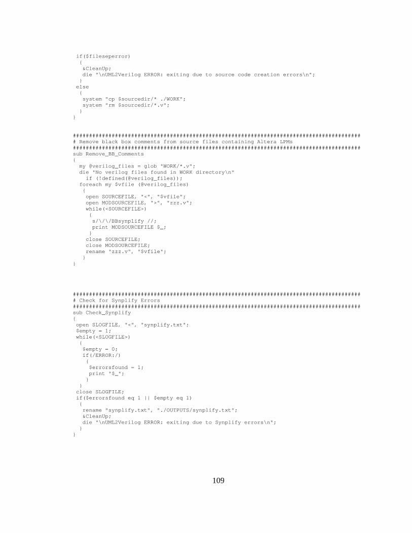
109
if($fileseperror) { &CleanUp; die "\nUML2Verilog ERROR: exiting due to source code creation errors\n"; } else { system "cp $sourcedir/* ./WORK"; system "rm $sourcedir/*.v"; } } ######################################################################################### # Remove black box comments from source files containing Altera LPMs ######################################################################################### sub Remove_BB_Comments { my @verilog_files = glob "WORK/*.v"; die "No verilog files found in WORK directory\n" if (!defined(@verilog_files)); foreach my $vfile (@verilog_files) { open SOURCEFILE, "<", "$vfile"; open MODSOURCEFILE, ">", "zzz.v"; while(<SOURCEFILE>) { s/\/\/BBsynplify //; print MODSOURCEFILE $_; } close SOURCEFILE; close MODSOURCEFILE; rename "zzz.v", "$vfile"; } } ######################################################################################### # Check for Synplify Errors ######################################################################################### sub Check_Synplify { open SLOGFILE, "<", "synplify.txt"; $empty = 1; while(<SLOGFILE>) { $empty = 0; if(/ERROR:/) { $errorsfound = 1; print "$_"; } } close SLOGFILE; if($errorsfound eq 1 || $empty eq 1) { rename "synplify.txt", "./OUTPUTS/synplify.txt"; &CleanUp; die "\nUML2Verilog ERROR: exiting due to Synplify errors\n"; } }

110
######################################################################################### # Check for XFlow Errors ######################################################################################### sub Check_XFlow { open XLOGFILE, "<", "xflowout.txt"; $empty = 1; while(<XLOGFILE>) { $empty = 0; if(/ERROR:/) { $errorsfound = 1; print "$_"; } } close XLOGFILE; if($errorsfound eq 1 || $empty eq 1) { rename "xflowout.txt", "./OUTPUTS/xflowout.txt"; &CleanUp; die "\nUML2Verilog ERROR: exiting due to Xflow errors\n"; } } ######################################################################################### # Check for QFlow Errors ######################################################################################### sub Check_QFlow { open QLOGFILE, "<", "quartus.tmp"; while(<QLOGFILE>) { if(/Error:/) { $errorsfound = 1; print "$_"; } } close QLOGFILE; if($errorsfound) { rename "quartus.tmp", "./OUTPUTS/quartusout.txt"; &CleanUp; die "\nUML2Verilog ERROR: exiting due to Qflow errors\n"; } }

111
######################################################################################### #Clean Up Work Area ######################################################################################### sub CleanUp { if (defined(glob "WORK/*.v")) {system "cp WORK/*.v ./OUTPUTS";} system "mv $xalandir/output.xml ./OUTPUTS"; rename "./OUTPUTS/output.xml", "./OUTPUTS/DAXML.xml"; if ("-x" eq $vendor) { if (-e "xflow.his") {system "rm xflow.his";} if (-e "WORK/$toplevel.bit") {system "cp WORK/$toplevel.bit ./OUTPUTS";} if (-e "WORK/$toplevel.msk") {system "cp WORK/$toplevel.msk ./OUTPUTS";} if (-e "xflowout.txt") {rename "./xflowout.txt", "./OUTPUTS/xflowout.txt";} if ("-syn" eq $synopt) { if (-e "WORK/$toplevel.edf") {system "mv WORK/$toplevel.edf ./OUTPUTS";} } } else { if (-e "$toplevel.sof") {system "mv $toplevel.sof ./OUTPUTS";} if (-e "$toplevel.pof") {system "mv $toplevel.pof ./OUTPUTS";} if (defined(glob "*.summary")) {system "mv *.summary ./OUTPUTS";} if (defined(glob "*.rpt")) {system "mv *.rpt ./OUTPUTS";} if (defined(glob "*.smsg")) {system "mv *.smsg ./OUTPUTS";} if (defined(glob "*.eqn")) {system "mv *.eqn ./OUTPUTS";} if (-e "$toplevel.tcl") {system "mv $toplevel.tcl ./OUTPUTS";} if (-e "$toplevel.pin") {system "mv $toplevel.pin ./OUTPUTS";} if (-e "db") {system "rm -r db";} if (-e "$toplevel.qsf") {system "rm $toplevel.qsf";} if (-e "$toplevel.qpf") {system "rm $toplevel.qpf";} if (-e "quartus.tmp") {system "rm quartus.tmp";} if ("-syn" eq $synopt) { if (-e "WORK/$toplevel.vqm") {system "mv WORK/$toplevel.vqm ./OUTPUTS";} } } if ("-syn" eq $synopt) { if (-e "synplify.txt") {rename "./synplify.txt", "./OUTPUTS/synplify.txt";} if (-e "$toplevel.srr") {rename "./$toplevel.srr", "./OUTPUTS/$toplevel.srr";} if (-e "$toplevel-syn.tcl") {system "mv $toplevel-syn.tcl ./OUTPUTS";} } if (-e "WORK") {system "rm -r WORK";} }

112
APPENDIX B
XMI-TO-DAXML XSLT RULES FILE
<?xml version="1.0" encoding="UTF-8"?> <xsl:stylesheet version="2.0" xmlns:xsl="http://www.w3.org/1999/XSL/Transform" xmlns:fo="http://www.w3.org/1999/XSL/Format" xmlns:xs="http://www.w3.org/2001/XMLSchema" xmlns:fn="http://www.w3.org/2005/02/xpath-functions" xmlns:xdt="http://www.w3.org/2005/02/xpath-datatypes" xmlns:UML="href://org.omg/UML/1.3" xmlns:xalan="http://xml.apache.org/xalan" exclude-result-prefixes="xalan"> <xsl:output method="xml" version="1.0" encoding="UTF-8" indent="yes"/> <!-- Compute log2 --> <xsl:template name="log2"> <!-- named template called by main template below --> <xsl:param name="i"/> <xsl:param name="count"/> <xsl:param name="maxValue"/> <xsl:choose> <!-- If there are more iterations to do, add the passed value of pi to another round of calculations. --> <xsl:when test="$i < $maxValue"> <xsl:call-template name="log2"> <xsl:with-param name="i" select="$i *2"/> <xsl:with-param name="count" select="$count + 1"/> <xsl:with-param name="maxValue" select="$maxValue"/> </xsl:call-template> </xsl:when> <!-- If no more iterations to do, add computed value to result tree. --> <xsl:otherwise> <xsl:value-of select="$count"/> </xsl:otherwise> </xsl:choose> </xsl:template> <!-- General XSLT Variables --> <xsl:variable name="modelname" select="/XMI/XMI.content/UML:Model/@name"/> <xsl:variable name="stateid" select="/XMI/XMI.content/UML:Model/
UML:Namespace.ownedElement/UML:StateMachine/UML:StateMachine.top/ UML:CompositeState/UML:CompositeState.subvertex/UML:SimpleState/@xmi.id"/>
<xsl:variable name="transition" select="/XMI/XMI.content/UML:Model/ UML:Namespace.ownedElement/UML:StateMachine/UML:StateMachine.transitions/ UML:Transition/@xmi.id"/>
<xsl:variable name="signal" select="/XMI/XMI.content/UML:Model/ UML:Namespace.ownedElement/UML:SignalEvent/@xmi.id"/>
<xsl:variable name="comments" select="/XMI/XMI.content/UML:Model/ UML:Namespace.ownedElement/UML:Comment/@name"/>
<xsl:variable name="morecomments" select="/XMI/XMI.content/UML:Model/ UML:Namespace.ownedElement/UML:Comment/UML:ModelElement.name"/>

113
<xsl:variable name="component" select="/XMI/XMI.content/UML:Model/ UML:Namespace.ownedElement/UML:Subsystem/UML:Namespace.ownedElement/UML:Component/@xmi.id"/>
<xsl:variable name="dependency" select="/XMI/XMI.content/UML:Model/ UML:Namespace.ownedElement/UML:Subsystem/UML:Namespace.ownedElement/UML:Dependency/@xmi.id"/>
<xsl:variable name="net" select="/XMI/XMI.content/UML:Model/ UML:Namespace.ownedElement/UML:Subsystem/UML:Namespace.ownedElement/UML:Comment/ @xmi.id"/>
<!-- Main Template Match --> <xsl:template match="/"> <daxml version="1.0"> <Model> <xsl:attribute name="name"> <xsl:value-of select="./XMI/XMI.content/UML:Model/@name"/> </xsl:attribute> </Model> <comments> <!-- Identify DAXML comment types --> <xsl:for-each select="$comments"> <xsl:variable name="pname" select="substring-before(.,':')"/> <xsl:variable name="pcontent" select="substring-after(.,':')"/> <xsl:if test="($pname='CODINGSTYLE')"> <xsl:element name="{$pname}"> <xsl:value-of select="$pcontent"/> </xsl:element> </xsl:if> <xsl:if test="($pname='INITIALSTATE')"> <xsl:element name="{$pname}"> <xsl:value-of select="$pcontent"/> </xsl:element> </xsl:if> <xsl:if test="($pname='DATARANGE')"> <xsl:variable name="perdata" select="xalan:tokenize($pcontent,';')"/> <xsl:element name="{$pname}"> <xsl:for-each select="$perdata"> <comments.DATARANGE> <xsl:attribute name="name"> <xsl:value-of select="substring-before(.,'.')"/> </xsl:attribute> <xsl:variable name="claim" select="substring-after(.,'.')"/> <xsl:variable name="claimvalue" select="substring-before($claim,'=')"/> <xsl:attribute name="maxValue"> <xsl:value-of select="substring-after($claim,'=')"/> </xsl:attribute> <xsl:if test="($claimvalue='list')"> <xsl:variable name="perlist" select="xalan:tokenize($claim,',')"/> <xsl:attribute name="maxValue"> <xsl:value-of select="count($perlist)"/> </xsl:attribute> <xsl:attribute name="list"> <xsl:value-of select="substring-after($claim,'=')"/> </xsl:attribute> </xsl:if> </comments.DATARANGE> </xsl:for-each> </xsl:element> </xsl:if> </xsl:for-each> <!-- Identify DAXML comment types --> <xsl:for-each select="$morecomments"> <xsl:variable name="pname" select="substring-before(.,':')"/> <xsl:variable name="pcontent" select="substring-after(.,':')"/> <xsl:if test="($pname='DATARANGE')">

114
<xsl:variable name="perdata" select="xalan:tokenize($pcontent,';')"/> <xsl:element name="{$pname}"> <xsl:for-each select="$perdata"> <comments.DATARANGE> <xsl:attribute name="name"> <xsl:value-of select="substring-before(.,'.')"/> </xsl:attribute> <xsl:variable name="claim" select="substring-after(.,'.')"/> <xsl:variable name="claimvalue" select="substring-before($claim,'=')"/> <xsl:if test="($claimvalue='max')"> <xsl:attribute name="maxValue"> <xsl:value-of select="substring-after($claim,'=')"/> </xsl:attribute> </xsl:if> <xsl:if test="($claimvalue='list')"> <xsl:variable name="perlist" select="xalan:tokenize($claim,',')"/> <xsl:attribute name="maxValue"> <xsl:value-of select="count($perlist)"/> </xsl:attribute> <xsl:attribute name="list"> <xsl:value-of select="substring-after($claim,'=')"/> </xsl:attribute> </xsl:if> </comments.DATARANGE> </xsl:for-each> </xsl:element> </xsl:if> </xsl:for-each> </comments> <!-- Process each controller state --> <xsl:for-each select="$stateid"> <state> <xsl:attribute name="id"> <xsl:value-of select="../@name"/> </xsl:attribute> <!-- find outgoing state transitions --> <xsl:variable name="transitionid" select="xalan:tokenize(../@outgoing,' ')"/> <xsl:for-each select="$transitionid"> <xsl:variable name="transitionidone" select="."/> <!-- define "next" state for transition --> <xsl:variable name="targetname"> <xsl:for-each select="$transition"> <xsl:if test="../@xmi.id = $transitionidone"> <xsl:variable name="targetid" select="../@target"/> <xsl:for-each select="$stateid"> <xsl:if test="../@xmi.id = $targetid"> <xsl:value-of select="../@name"/> </xsl:if> </xsl:for-each> </xsl:if> </xsl:for-each> </xsl:variable> <!-- define transition event trigger signal --> <xsl:variable name="signalname"> <xsl:for-each select="$transition"> <xsl:if test="../@xmi.id = $transitionidone"> <xsl:variable name="signalid" select="../@trigger"/> <xsl:for-each select="$signal"> <xsl:if test="../@xmi.id = $signalid"> <xsl:value-of select="../@name"/> </xsl:if> </xsl:for-each> </xsl:if> </xsl:for-each> </xsl:variable> <!-- create DAXML transition element -->
115
<transition> <xsl:choose> <xsl:when test="contains($signalname,'@') "> <xsl:variable name="eventname" select="substring-before($signalname,'(@')"/> <xsl:variable name="conda" select="substring-after($signalname,'@')"/> <xsl:variable name="cond" select="substring-before($conda,')=')"/> <xsl:variable name="eventvalue" select="substring-after($conda,')=')"/> <xsl:attribute name="event"> <xsl:value-of select="$eventname"/> </xsl:attribute> <xsl:attribute name="value"> <xsl:value-of select="$eventvalue"/> </xsl:attribute> <xsl:attribute name="cond"> <xsl:value-of select="$cond"/> </xsl:attribute> </xsl:when> <xsl:when test="contains($signalname,'=')"> <xsl:variable name="eventname" select="substring-before($signalname,'=')"/> <xsl:variable name="eventvalue" select="substring-after($signalname,'=')"/> <xsl:attribute name="event"> <xsl:value-of select="$eventname"/> </xsl:attribute> <xsl:attribute name="value"> <xsl:value-of select="$eventvalue"/> </xsl:attribute> </xsl:when> <xsl:otherwise> <xsl:attribute name="event"> <xsl:value-of select="$signalname"/> </xsl:attribute> </xsl:otherwise> </xsl:choose> <target> <xsl:attribute name="next"> <xsl:value-of select="$targetname"/> </xsl:attribute> </target> </transition> </xsl:for-each> <!-- define "on entry" state behavior --> <onentry> <xsl:for-each select="../UML:State.entry/UML:ActionSequence/
UML:ActionSequence.action/UML:SendAction/@name"> <assign> <xsl:attribute name="name"> <xsl:value-of select="../@name"/> </xsl:attribute> <xsl:attribute name="expr"> <xsl:value-of select="../UML:Action.actualArgument/UML:Argument/
UML:Argument.value/UML:Expression/@body"/> </xsl:attribute> </assign> </xsl:for-each> </onentry> <!-- define state behavior --> <xsl:for-each select="../UML:State.doActivity/UML:ActionSequence/
UML:ActionSequence.action/UML:SendAction/@name"> <assign> <xsl:attribute name="name"> <xsl:value-of select="../@name"/> </xsl:attribute> <xsl:attribute name="expr"> <xsl:value-of select="../UML:Action.actualArgument/UML:Argument/
UML:Argument.value/UML:Expression/@body"/> </xsl:attribute> </assign>

116
</xsl:for-each> </state> </xsl:for-each> <!-- Process Datapath Elements --> <components> <!-- define top-level I/O ports --> <ports> <inputs> <!-- find top-level inputs --> <xsl:for-each select="$component"> <xsl:variable name="componentname" select="../@name"/> <xsl:variable name="componenttype" select="substring-before($componentname,':')"/> <xsl:if test="$componenttype = 'IN'"> <xsl:element name="input"> <xsl:value-of select="substring-after($componentname,':')"/> <!-- look for port width definition in DATARANGE block --> <xsl:for-each select="$net"> <xsl:if test="contains(../@name,'DATARANGE')"> <xsl:variable name="rangelist" select="substring-after(../@name,':')"/> <xsl:variable name="ranges" select="xalan:tokenize($rangelist,';')"/> <xsl:for-each select="$ranges"> <xsl:variable name="rangenet" select="substring-before(.,'.')"/> <xsl:if test="substring-after($componentname,':') = $rangenet"> <xsl:variable name="temp" select="substring-after(.,'.')"/> <xsl:variable name="rangetype" select="substring-before($temp,'=')"/> <xsl:if test="$rangetype = 'width'"> <xsl:value-of select="'['"/> <xsl:value-of select="substring-after($temp,'=')-1"/> <xsl:value-of select="':0]'"/> </xsl:if> <xsl:if test="$rangetype = 'max'"> <xsl:variable name="buswidth"> <xsl:call-template name="log2"> <xsl:with-param name="i" select="1"/> <xsl:with-param name="count" select="0"/> <xsl:with-param name="maxValue" select="substring-after($temp,'=')"/> </xsl:call-template> </xsl:variable> <xsl:if test="$buswidth>1"> <xsl:value-of select="'['"/> <xsl:value-of select="number($buswidth)-1"/> <xsl:value-of select="':0]'"/> </xsl:if> </xsl:if> </xsl:if> </xsl:for-each> </xsl:if> </xsl:for-each> </xsl:element> </xsl:if> </xsl:for-each> </inputs> <outputs> <!-- find top-level outputs --> <xsl:for-each select="$component"> <xsl:variable name="componentname" select="../@name"/> <xsl:variable name="componenttype" select="substring-before($componentname,':')"/> <xsl:if test="$componenttype = 'OUT'"> <xsl:element name="output"> <xsl:value-of select="substring-after($componentname,':')"/> <!-- look for port width definition in DATARANGE block --> <xsl:for-each select="$net"> <xsl:if test="contains(../@name,'DATARANGE')"> <xsl:variable name="rangelist" select="substring-after(../@name,':')"/> <xsl:variable name="ranges" select="xalan:tokenize($rangelist,';')"/> <xsl:for-each select="$ranges">
117
<xsl:variable name="rangenet" select="substring-before(.,'.')"/> <xsl:if test="substring-after($componentname,':') = $rangenet"> <xsl:variable name="temp" select="substring-after(.,'.')"/> <xsl:variable name="rangetype" select="substring-before($temp,'=')"/> <xsl:if test="$rangetype = 'width'"> <xsl:value-of select="'['"/> <xsl:value-of select="substring-after($temp,'=')-1"/> <xsl:value-of select="':0]'"/> </xsl:if> <xsl:if test="$rangetype = 'max'"> <xsl:variable name="buswidth"> <xsl:call-template name="log2"> <xsl:with-param name="i" select="1"/> <xsl:with-param name="count" select="0"/> <xsl:with-param name="maxValue" select="substring-after($temp,'=')"/> </xsl:call-template> </xsl:variable> <xsl:if test="$buswidth>1"> <xsl:value-of select="'['"/> <xsl:value-of select="number($buswidth)-1"/> <xsl:value-of select="':0]'"/> </xsl:if> </xsl:if> </xsl:if> </xsl:for-each> </xsl:if> </xsl:for-each> </xsl:element> </xsl:if> </xsl:for-each> </outputs> </ports> <!-- define internal nets --> <wires> <xsl:for-each select="$net"> <xsl:variable name="netname" select="../@name"/> <xsl:if test="not(contains($netname,'DATARANGE'))"> <xsl:element name="wire"> <xsl:value-of select="$netname"/> <!-- look for port width definition in DATARANGE block --> <xsl:for-each select="$net"> <xsl:if test="contains(../@name,'DATARANGE')"> <xsl:variable name="rangelist" select="substring-after(../@name,':')"/> <xsl:variable name="ranges" select="xalan:tokenize($rangelist,';')"/> <xsl:for-each select="$ranges"> <xsl:variable name="rangenet" select="substring-before(.,'.')"/> <xsl:if test="$netname = $rangenet"> <xsl:variable name="temp" select="substring-after(.,'.')"/> <xsl:variable name="rangetype" select="substring-before($temp,'=')"/> <xsl:if test="$rangetype = 'width'"> <xsl:value-of select="'['"/> <xsl:value-of select="substring-after($temp,'=')-1"/> <xsl:value-of select="':0]'"/> </xsl:if> <xsl:if test="$rangetype = 'max'"> <xsl:variable name="buswidth"> <xsl:call-template name="log2"> <xsl:with-param name="i" select="1"/> <xsl:with-param name="count" select="0"/> <xsl:with-param name="maxValue" select="substring-after($temp,'=')"/> </xsl:call-template> </xsl:variable> <xsl:if test="$buswidth>1"> <xsl:value-of select="'['"/> <xsl:value-of select="number($buswidth)-1"/> <xsl:value-of select="':0]'"/>

118
</xsl:if> </xsl:if> </xsl:if> </xsl:for-each> </xsl:if> </xsl:for-each> </xsl:element> </xsl:if> </xsl:for-each> </wires> <!-- define datapath modules --> <xsl:for-each select="$component"> <xsl:variable name="component_id" select="."/> <xsl:variable name="componentname" select="../@name"/> <xsl:variable name="componenttype" select="substring-before($componentname,':')"/> <xsl:if test="$componenttype = ''"> <xsl:element name="component"> <xsl:attribute name="module"> <xsl:choose> <xsl:when test="substring-after(../@name,'#') = ''"> <xsl:value-of select="../@name"/> </xsl:when> <xsl:otherwise> <xsl:value-of select="substring-before(../@name,'#')"/> </xsl:otherwise> </xsl:choose> </xsl:attribute> <!-- find module input ports --> <xsl:element name="inputs"> <xsl:for-each select="$dependency"> <!-- search dependencies for current component ID --> <xsl:variable name="sourceport_id" select="../@supplier"/> <xsl:if test="$sourceport_id = $component_id"> <xsl:element name="input"> <xsl:variable name="dependency_id" select="."/> <xsl:for-each select="$component"> <!-- search PORT components for matching outgoing dependency --> <xsl:variable name="egress_dependency_id" select="../@clientDependency"/> <xsl:variable name="ingress_dependency_id" select="../@supplierDependency"/> <xsl:if test="$egress_dependency_id = $dependency_id"> <xsl:attribute name="port"> <xsl:if test="not(contains(../@name,'['))"> <xsl:value-of select="substring-after(../@name,'.')"/> </xsl:if> <xsl:if test="contains(../@name,'[')"> <xsl:variable name="temp" select="substring-before(../@name,'[')"/> <xsl:value-of select="substring-after($temp,'.')"/> </xsl:if> </xsl:attribute> <xsl:if test="contains(../@name,'[')"> <xsl:variable name="temp1" select="substring-after(../@name,'[')"/> <xsl:variable name="spectype" select="substring-before($temp1,'=')"/> <xsl:variable name="temp2" select="substring-after($temp1,'=')"/> <xsl:variable name="specvalue" select="substring-before($temp2,']')"/> <xsl:if test="$spectype = 'width'"> <xsl:attribute name="width"> <xsl:value-of select="$specvalue"/> </xsl:attribute> </xsl:if> <xsl:if test="$spectype = 'max'"> <xsl:attribute name="maxval"> <xsl:value-of select="$specvalue"/> </xsl:attribute> </xsl:if> </xsl:if> <xsl:for-each select="$dependency">
119
<!-- search dependencies for matching PORT input --> <xsl:if test="$ingress_dependency_id = ."> <xsl:variable name="source_id" select="../@client"/> <xsl:for-each select="$component"> <!-- search components for source port/input --> <xsl:if test="$source_id = ."> <xsl:if test="substring-before(../@name,':') = 'PORT'"> <xsl:for-each select="$net"> <!-- search net names for ingress dependency ID --> <xsl:if test="../@annotatedElement = $ingress_dependency_id"> <xsl:value-of select="../@name"/> </xsl:if> </xsl:for-each> </xsl:if> <xsl:if test="substring-before(../@name,':') = 'IN'"> <xsl:value-of select="substring-after(../@name,':')"/> </xsl:if> </xsl:if> </xsl:for-each> </xsl:if> </xsl:for-each> </xsl:if> </xsl:for-each> </xsl:element> </xsl:if> </xsl:for-each> </xsl:element> <!-- find module output ports --> <xsl:element name="outputs"> <xsl:for-each select="$dependency"> <!-- search dependencies for current component ID --> <xsl:variable name="destinationport_id" select="../@client"/> <xsl:if test="$destinationport_id = $component_id"> <xsl:element name="output"> <xsl:variable name="dependency_id" select="."/> <xsl:for-each select="$component"> <!-- search PORT components for matching incoming dependency --> <xsl:variable name="egress_dependency_id" select="../@clientDependency"/> <xsl:variable name="ingress_dependency_id" select="../@supplierDependency"/> <xsl:if test="$ingress_dependency_id = $dependency_id"> <xsl:attribute name="port"> <xsl:if test="not(contains(../@name,'['))"> <xsl:value-of select="substring-after(../@name,'.')"/> </xsl:if> <xsl:if test="contains(../@name,'[')"> <xsl:variable name="temp1" select="substring-before(../@name,'[')"/> <xsl:value-of select="substring-after($temp1,'.')"/> </xsl:if> </xsl:attribute> <xsl:if test="contains(../@name,'[')"> <xsl:variable name="temp1" select="substring-after(../@name,'[')"/> <xsl:variable name="spectype" select="substring-before($temp1,'=')"/> <xsl:variable name="temp2" select="substring-after($temp1,'=')"/> <xsl:variable name="specvalue" select="substring-before($temp2,']')"/> <xsl:if test="$spectype = 'width'"> <xsl:attribute name="width"> <xsl:value-of select="$specvalue"/> </xsl:attribute> </xsl:if> <xsl:if test="$spectype = 'max'"> <xsl:attribute name="maxval"> <xsl:value-of select="$specvalue"/> </xsl:attribute> </xsl:if> </xsl:if> <xsl:for-each select="$dependency"> <!-- search dependencies for PORT output (tokenize for mult. outputs) -->
120
<xsl:variable name="current_dependency_id" select="."/> <xsl:variable name="current_supplier" select="../@supplier"/> <xsl:variable name="egress_dependency"> <xsl:choose> <xsl:when test="contains($egress_dependency_id,' ')"> <xsl:value-of select="substring-before($egress_dependency_id,' ')"/> </xsl:when> <xsl:otherwise> <xsl:value-of select="$egress_dependency_id"/> </xsl:otherwise> </xsl:choose> </xsl:variable> <xsl:if test="$egress_dependency = $current_dependency_id"> <xsl:variable name="destination_id" select="$current_supplier"/> <xsl:for-each select="$component"> <!-- search components for destination port/output --> <xsl:if test="$destination_id = ."> <xsl:if test="substring-before(../@name,':') = 'PORT'"> <xsl:for-each select="$net"> <!-- search net names for egress dependency ID --> <xsl:if test="../@annotatedElement = $egress_dependency"> <xsl:value-of select="../@name"/> </xsl:if> </xsl:for-each> </xsl:if> <xsl:if test="substring-before(../@name,':') = 'OUT'"> <xsl:value-of select="substring-after(../@name,':')"/> </xsl:if> </xsl:if> </xsl:for-each> </xsl:if> </xsl:for-each> </xsl:if> </xsl:for-each> </xsl:element> </xsl:if> </xsl:for-each> </xsl:element> </xsl:element> </xsl:if> </xsl:for-each> </components> </daxml> </xsl:template> </xsl:stylesheet>

121
APPENDIX C
DAXML-TO-VERILOG XSLT RULES FILE
<?xml version="1.0" encoding="UTF-8"?> <xsl:stylesheet version="2.0" xmlns:xsl="http://www.w3.org/1999/XSL/Transform" xmlns:fo="http://www.w3.org/1999/XSL/Format" xmlns:xs="http://www.w3.org/2001/XMLSchema" xmlns:xdt="http://www.w3.org/2005/02/xpath-datatypes" xmlns:xalan="http://xml.apache.org/xalan" exclude-result-prefixes="xalan"> <xsl:output method="text"/> <!-- Compute log2 --> <xsl:template name="log2"> <!-- named template called by main template below --> <xsl:param name="i"/> <xsl:param name="count"/> <xsl:param name="maxValue"/> <xsl:choose> <!-- If there are more iterations to do, add the passed value of pi to another round of calculations. --> <xsl:when test="$i < $maxValue"> <xsl:call-template name="log2"> <xsl:with-param name="i" select="$i *2"/> <xsl:with-param name="count" select="$count + 1"/> <xsl:with-param name="maxValue" select="$maxValue"/> </xsl:call-template> </xsl:when> <!-- If no more iterations to do, add computed value to result tree. --> <xsl:otherwise> <xsl:value-of select="$count"/> </xsl:otherwise> </xsl:choose> </xsl:template> <!-- General XSLT Variables --> <xsl:variable name="modelname" select="/daxml/Model/@name"/> <xsl:variable name="state" select="/daxml/state/@id"/> <xsl:variable name="event" select="/daxml/state/transition/@event"/> <xsl:variable name="onentryassignname" select="/daxml/state/onentry/assign/@name"/> <xsl:variable name="assignname" select="/daxml/state/assign/@name"/> <xsl:variable name="codingstyle" select="/daxml/comments/CODINGSTYLE"/> <xsl:variable name="initialstate" select="/daxml/comments/INITIALSTATE"/> <xsl:variable name="datarange" select="/daxml/comments/DATARANGE"/> <xsl:variable name="zeros" select="'00000000000000000000000000000000'"/> <xsl:variable name="inputports" select="/daxml/components/ports/inputs"/> <xsl:variable name="outputports" select="/daxml/components/ports/outputs"/> <xsl:variable name="netwire" select="/daxml/components/wires/wire"/>
122
<!-- Main Template Match --> <xsl:template match="/"> <!-- Define Top Level Module --> <xsl:text>module </xsl:text><xsl:value-of select="$modelname"/><xsl:text>(</xsl:text> <!-- list top-level input ports --> <xsl:variable name="inputport" select="xalan:distinct($inputports/input)"/> <xsl:for-each select="$inputport"> <xsl:if test="contains(.,'[')"> <xsl:variable name="justname" select="substring-before(.,'[')"/> <xsl:value-of select="$justname"/><xsl:text>,</xsl:text> </xsl:if> <xsl:if test="not(contains(.,'['))"> <xsl:value-of select="."/><xsl:text>,</xsl:text> </xsl:if> </xsl:for-each> <!-- list top-level output ports --> <xsl:variable name="outputport" select="xalan:distinct($outputports/output)"/> <xsl:for-each select="$outputport"> <xsl:if test="contains(.,'[')"> <xsl:variable name="justname" select="substring-before(.,'[')"/> <xsl:value-of select="$justname"/> <xsl:if test="position() != last()"> <xsl:text>,</xsl:text> </xsl:if> </xsl:if> <xsl:if test="not(contains(.,'['))"> <xsl:value-of select="."/> <xsl:if test="position() != last()"> <xsl:text>,</xsl:text> </xsl:if> </xsl:if> </xsl:for-each><xsl:text>); </xsl:text> <!-- input port declarations --> <xsl:for-each select="$inputport"> <xsl:text> input </xsl:text> <xsl:if test="contains(.,'[')"> <xsl:variable name="justname" select="substring-before(.,'[')"/> <xsl:variable name="justindex" select="substring-after(.,$justname)"/> <xsl:value-of select="$justindex"/><xsl:text> </xsl:text> <xsl:value-of select="$justname"/><xsl:text>;</xsl:text> </xsl:if> <xsl:if test="not(contains(.,'['))"> <xsl:value-of select="."/><xsl:text>;</xsl:text> </xsl:if> </xsl:for-each> <xsl:text> </xsl:text> <!-- output port declarations --> <xsl:for-each select="$outputport"> <xsl:text> output </xsl:text> <xsl:if test="contains(.,'[')"> <xsl:variable name="justname" select="substring-before(.,'[')"/> <xsl:variable name="justindex" select="substring-after(.,$justname)"/> <xsl:value-of select="$justindex"/><xsl:text> </xsl:text> <xsl:value-of select="$justname"/><xsl:text>;</xsl:text> </xsl:if> <xsl:if test="not(contains(.,'['))"> <xsl:value-of select="."/><xsl:text>;</xsl:text> </xsl:if> </xsl:for-each> <xsl:text> </xsl:text> <!-- internal wire declarations --> <xsl:variable name="internalwire" select="xalan:distinct($netwire)"/> <xsl:for-each select="$internalwire"> <xsl:sort/> <xsl:text> wire </xsl:text> <xsl:if test="contains(.,'[')"> <xsl:variable name="justname" select="substring-before(.,'[')"/>

123
<xsl:variable name="justindex" select="substring-after(.,$justname)"/> <xsl:value-of select="$justindex"/><xsl:text> </xsl:text> <xsl:value-of select="$justname"/><xsl:text>;</xsl:text> </xsl:if> <xsl:if test="not(contains(.,'['))"> <xsl:value-of select="."/><xsl:text>;</xsl:text> </xsl:if> </xsl:for-each> <xsl:text> </xsl:text> <!-- datapath module instantiations --> <xsl:variable name="modname" select="/daxml/components/component/@module"/> <xsl:for-each select="$modname"> <xsl:sort/> <xsl:variable name="modulename" select="."/> <xsl:text> </xsl:text> <xsl:value-of select="$modulename"/><xsl:text> u</xsl:text> <xsl:value-of select="position()"/><xsl:text>_</xsl:text> <xsl:value-of select="$modulename"/><xsl:text> ( </xsl:text> <!-- define port associations for module inputs --> <xsl:variable name="compinport" select="../inputs/input"/> <xsl:for-each select="$compinport"> <xsl:text> .</xsl:text> <xsl:value-of select="./@port"/><xsl:text>(</xsl:text> <xsl:value-of select="."/><xsl:text>), </xsl:text> </xsl:for-each> <!-- define port associations for module outputs --> <xsl:variable name="compoutport" select="../outputs/output"/> <xsl:for-each select="$compoutport"> <xsl:text> .</xsl:text> <xsl:value-of select="./@port"/><xsl:text>(</xsl:text> <xsl:value-of select="."/> <xsl:if test="position() != last()"> <xsl:text>), </xsl:text> </xsl:if> <xsl:if test="position() = last()"> <xsl:text>)); </xsl:text> </xsl:if> </xsl:for-each> </xsl:for-each> <xsl:text> endmodule </xsl:text> <xsl:text> ================================================= </xsl:text> <!-- Define Individual datapath modules --> <xsl:variable name="component" select="xalan:distinct(/daxml/components/component)"/> <xsl:for-each select="$component"> <xsl:sort select="./@module"/> <xsl:variable name="modulename" select="./@module"/> <xsl:if test="$modulename != 'controller'"> <!-- assign reference designator --> <xsl:text>//u</xsl:text> <xsl:value-of select="position()"/> <xsl:text> </xsl:text> <!-- module declaration --> <xsl:text>module </xsl:text> <xsl:value-of select="$modulename"/> <xsl:text>(</xsl:text> <xsl:variable name="compinport" select="./inputs/input"/> <xsl:for-each select="$compinport"> <xsl:sort select="./@port"/> <xsl:value-of select="./@port"/><xsl:text>,</xsl:text> </xsl:for-each> <xsl:variable name="compoutport" select="./outputs/output"/> <xsl:for-each select="$compoutport"> <xsl:sort select="./@port"/> <xsl:value-of select="./@port"/> <xsl:if test="position() != last()">

124
<xsl:text>,</xsl:text> </xsl:if> </xsl:for-each> <xsl:text>); </xsl:text> <!-- input port declarations --> <xsl:for-each select="$compinport"> <xsl:sort select="./@port"/> <xsl:text>input </xsl:text> <xsl:variable name="width" select="./@width"/> <xsl:if test="count($width) > 0"> <xsl:text>[</xsl:text> <xsl:value-of select="$width - 1"/> <xsl:text>:0] </xsl:text> </xsl:if> <xsl:variable name="maxval" select="./@maxval"/> <xsl:if test="count($maxval) > 0"> <xsl:variable name="buswidth"> <xsl:call-template name="log2"> <xsl:with-param name="i" select="1"/> <xsl:with-param name="count" select="0"/> <xsl:with-param name="maxValue" select="$maxval"/> </xsl:call-template> </xsl:variable> <xsl:if test="$buswidth > 1"> <xsl:text>[</xsl:text> <xsl:value-of select="$buswidth - 1"/> <xsl:text>:0] </xsl:text> </xsl:if> </xsl:if> <xsl:value-of select="./@port"/> <xsl:text>; </xsl:text> </xsl:for-each> <xsl:text> </xsl:text> <!-- output port declarations --> <xsl:for-each select="$compoutport"> <xsl:sort select="./@port"/> <xsl:text>output </xsl:text> <xsl:variable name="width" select="./@width"/> <xsl:if test="count($width) > 0"> <xsl:text>[</xsl:text> <xsl:value-of select="$width - 1"/> <xsl:text>:0] </xsl:text> </xsl:if> <xsl:variable name="maxval" select="./@maxval"/> <xsl:if test="count($maxval) > 0"> <xsl:variable name="buswidth"> <xsl:call-template name="log2"> <xsl:with-param name="i" select="1"/> <xsl:with-param name="count" select="0"/> <xsl:with-param name="maxValue" select="$maxval"/> </xsl:call-template> </xsl:variable> <xsl:if test="$buswidth > 1"> <xsl:text>[</xsl:text> <xsl:value-of select="$buswidth - 1"/> <xsl:text>:0] </xsl:text> </xsl:if> </xsl:if> <xsl:value-of select="./@port"/> <xsl:text>; </xsl:text> </xsl:for-each> <xsl:text> </xsl:text> <!-- leave empty space to be filled in with source templates --> <xsl:text>endmodule </xsl:text> <xsl:text> ================================================= </xsl:text> </xsl:if> </xsl:for-each>

125
<!-- Define Controller Module --> <xsl:variable name="codelength"> <!-- determine number of state encoding bits --> <xsl:choose> <xsl:when test="$codingstyle = 'gray'"> <xsl:call-template name="log2"> <xsl:with-param name="i" select="1"/> <xsl:with-param name="count" select="0"/> <xsl:with-param name="maxValue" select="count($state)"/> </xsl:call-template> </xsl:when> <xsl:when test="$codingstyle = 'onehot'"> <xsl:value-of select="count($state)"/> </xsl:when> <xsl:otherwise> <xsl:call-template name="log2"> <xsl:with-param name="i" select="1"/> <xsl:with-param name="count" select="0"/> <xsl:with-param name="maxValue" select="count($state)"/> </xsl:call-template> </xsl:otherwise> </xsl:choose> </xsl:variable> <!-- assign state encoding constants --> <xsl:choose> <xsl:when test="$codingstyle = 'gray'"> <xsl:for-each select="daxml/state"> <xsl:text>`define </xsl:text> <xsl:value-of select="@id"/><xsl:text> 2'b00 </xsl:text> </xsl:for-each> </xsl:when> <xsl:when test="$codingstyle = 'onehot'"> <xsl:for-each select="daxml/state"> <xsl:variable name="half2" select="substring(($zeros),1,count($state)-position())"/> <xsl:variable name="half1" select="substring(($zeros),1,position()-1)"/> <xsl:variable name="code" select="concat(concat($half1,'1'),$half2)"/> <xsl:text>`define </xsl:text> <xsl:value-of select="@id"/> <xsl:text> </xsl:text> <xsl:value-of select="$codelength"/> <xsl:text>'b</xsl:text> <xsl:value-of select="$code"/> <xsl:text> </xsl:text> </xsl:for-each> </xsl:when> <xsl:otherwise> <xsl:for-each select="daxml/state"> <xsl:text>`define </xsl:text> <xsl:value-of select="@id"/> <xsl:text> </xsl:text> <xsl:number value="position()-1" format="1"/> <xsl:text> </xsl:text> </xsl:for-each> </xsl:otherwise> </xsl:choose> <!-- assign other constant values --> <xsl:for-each select="$datarange/comments.DATARANGE/@list"> <xsl:if test="count(.)>0"> <xsl:variable name="perlista" select="substring-after(.,'{')"/> <xsl:variable name="perlistb" select="substring-before($perlista,'}')"/> <xsl:variable name="perlist" select="xalan:tokenize($perlistb,',')"/> <xsl:for-each select="$perlist"> <xsl:text>`define </xsl:text> <xsl:value-of select="."/> <xsl:text> </xsl:text> <xsl:number value="position()-1" format="1"/> <xsl:text> </xsl:text>

126
</xsl:for-each> </xsl:if> </xsl:for-each> <!-- controller module declaration --> <xsl:text> module </xsl:text> <xsl:text>controller(</xsl:text> <xsl:variable name="events" select="xalan:distinct($event)"/> <xsl:for-each select="$events"> <xsl:if test="not(.='')"> <xsl:value-of select="."/><xsl:text>,</xsl:text> </xsl:if> </xsl:for-each> <xsl:variable name="onentryassignnames" select="xalan:distinct($onentryassignname)"/> <xsl:for-each select="$onentryassignnames"> <xsl:value-of select="."/><xsl:text>,</xsl:text> </xsl:for-each> <xsl:variable name="assignnames" select="xalan:distinct($assignname)"/> <xsl:for-each select="$assignnames"> <xsl:value-of select="."/><xsl:text>,</xsl:text> </xsl:for-each> <xsl:text>clk,reset); </xsl:text> <!-- input port declarations --> <xsl:text>input clk; </xsl:text> <xsl:text>input reset; </xsl:text> <xsl:for-each select="$events"> <xsl:if test="not(.='')"> <xsl:text>input </xsl:text> <xsl:value-of select="."/><xsl:text>; </xsl:text> </xsl:if> </xsl:for-each> <xsl:text> </xsl:text> <!-- output port declarations --> <xsl:for-each select="$onentryassignnames"> <xsl:variable name="onentrysignalname" select="."/> <xsl:variable name="buswidth"> <xsl:for-each select="$datarange/comments.DATARANGE/@name"> <xsl:if test="../@name = $onentrysignalname "> <xsl:call-template name="log2"> <xsl:with-param name="i" select="1"/> <xsl:with-param name="count" select="0"/> <xsl:with-param name="maxValue" select="../@maxValue"/> </xsl:call-template> </xsl:if> </xsl:for-each> </xsl:variable> <xsl:text>output </xsl:text> <xsl:if test="$buswidth>1"> <xsl:text>[</xsl:text> <xsl:value-of select="number($buswidth)-1"/> <xsl:text>:0] </xsl:text> </xsl:if> <xsl:value-of select="."/><xsl:text>; </xsl:text> <xsl:text>reg </xsl:text> <xsl:if test="$buswidth>1"> <xsl:text>[</xsl:text> <xsl:value-of select="number($buswidth)-1"/> <xsl:text>:0] </xsl:text> </xsl:if> <xsl:value-of select="."/><xsl:text>; </xsl:text> </xsl:for-each> <xsl:for-each select="$assignnames"> <xsl:variable name="assignsignalname" select="."/> <xsl:variable name="buswidth"> <xsl:for-each select="$datarange/comments.DATARANGE/@name"> <xsl:if test="contains($assignsignalname,../@name)"> <xsl:call-template name="log2"> <xsl:with-param name="i" select="1"/>
127
<xsl:with-param name="count" select="0"/> <xsl:with-param name="maxValue" select="../@maxValue"/> </xsl:call-template> </xsl:if> </xsl:for-each> </xsl:variable> <xsl:text>output </xsl:text> <xsl:if test="$buswidth>1"> <xsl:text>[</xsl:text> <xsl:value-of select="number($buswidth)-1"/> <xsl:text>:0] </xsl:text> </xsl:if> <xsl:value-of select="."/><xsl:text>; </xsl:text> <xsl:text>reg </xsl:text> <xsl:if test="$buswidth>1"> <xsl:text>[</xsl:text> <xsl:value-of select="number($buswidth)-1"/> <xsl:text>:0] </xsl:text> </xsl:if> <xsl:value-of select="."/><xsl:text>; </xsl:text> </xsl:for-each> <!-- state registers --> <xsl:text> </xsl:text> <xsl:text>reg [</xsl:text> <xsl:value-of select="number($codelength)-1"/> <xsl:text>:0] pstate,nstate; </xsl:text> <!-- sequential state transition always block --> <xsl:text> </xsl:text> <xsl:text>always@(posedge clk) </xsl:text> <xsl:text> begin </xsl:text> <xsl:text> if (reset == 1'b1) </xsl:text> <xsl:text> pstate = `</xsl:text> <xsl:value-of select="$initialstate"/> <xsl:text>; </xsl:text> <xsl:text> else </xsl:text> <xsl:text> pstate = nstate; </xsl:text> <xsl:text> end </xsl:text> <!-- combinational state behavior always block --> <xsl:text> </xsl:text> <xsl:text>always@(</xsl:text> <xsl:for-each select="$events"> <xsl:if test="not(.='')"> <xsl:value-of select="."/> <xsl:text> or </xsl:text> </xsl:if> </xsl:for-each> <xsl:text>pstate) </xsl:text> <xsl:text> begin </xsl:text> <xsl:text> case (pstate) </xsl:text> <!-- list behavior and transitions for each state --> <xsl:for-each select="daxml/state"> <xsl:text> `</xsl:text> <xsl:value-of select="@id"/> <xsl:text>: </xsl:text> <xsl:text> begin </xsl:text> <xsl:for-each select="./onentry/assign"> <xsl:text> </xsl:text> <xsl:value-of select="@name"/> <xsl:text> = </xsl:text> <xsl:value-of select="@expr"/> <xsl:text>; </xsl:text> </xsl:for-each> <xsl:for-each select="./assign"> <xsl:text> </xsl:text> <xsl:value-of select="@name"/> <xsl:text> = `</xsl:text> <xsl:value-of select="@expr"/>
128
<xsl:text>; </xsl:text> </xsl:for-each> <xsl:text> </xsl:text> <xsl:choose> <!-- behavior with 2 outgoing transitions --> <xsl:when test="count(./transition)>1"> <xsl:for-each select="./transition"> <xsl:if test="position()=1"> <xsl:text> if(</xsl:text> <xsl:value-of select="@event"/> <xsl:if test="count(@value)>0"> <xsl:text> == `</xsl:text> <xsl:value-of select="@value"/> <xsl:text>) </xsl:text> </xsl:if> <xsl:if test="count(@cond)>0"> <xsl:text> && (</xsl:text> <xsl:value-of select="@cond"/> <xsl:text>) </xsl:text> </xsl:if> <xsl:text> nstate=`</xsl:text> <xsl:value-of select="target/@next"/> <xsl:text>; </xsl:text> </xsl:if> <xsl:if test="position()>1"> <xsl:text> else if(</xsl:text> <xsl:value-of select="@event"/> <xsl:if test="count(@value)>0"> <xsl:text>==`</xsl:text> <xsl:value-of select="@value"/> </xsl:if> <xsl:if test="count(@cond)>0"> <xsl:text> && (</xsl:text> <xsl:value-of select="@cond"/> <xsl:text>)</xsl:text> </xsl:if> <xsl:text>) </xsl:text> <xsl:text> nstate=`</xsl:text> <xsl:value-of select="target/@next"/> <xsl:text>; </xsl:text> </xsl:if> </xsl:for-each> <xsl:text> else </xsl:text> <xsl:text> nstate=`</xsl:text> <xsl:value-of select="./@id"/> <xsl:text>; </xsl:text> <xsl:text> end </xsl:text> <xsl:text> </xsl:text> </xsl:when> <!-- behavior with 1 outgoing transition --> <xsl:when test="count(./transition)=1"> <xsl:if test="count(./transition/@event)>0"> <xsl:variable name="transevent" select="./transition/@event"/> <xsl:choose> <xsl:when test="not($transevent='')"> <xsl:text> if(</xsl:text> <xsl:value-of select="./transition/@event"/> <xsl:if test="count(./transition/@value)>0"> <xsl:text> == `</xsl:text> <xsl:value-of select="./transition/@value"/> </xsl:if> <xsl:if test="count(./transition/@cond)>0"> <xsl:text> && (</xsl:text> <xsl:value-of select="./transition/@cond"/> <xsl:text>)</xsl:text> </xsl:if> <xsl:text>) </xsl:text>
129
<xsl:text> nstate=`</xsl:text> <xsl:value-of select="./transition/target/@next"/> <xsl:text>; </xsl:text> <xsl:text> else </xsl:text> <xsl:text> nstate=`</xsl:text> <xsl:value-of select="./@id"/> <xsl:text>; </xsl:text> </xsl:when> <xsl:when test="$transevent=''"> <xsl:text> nstate=`</xsl:text> <xsl:value-of select="./transition/target/@next"/> <xsl:text>; </xsl:text> </xsl:when> </xsl:choose> <xsl:text> end </xsl:text> <xsl:text> </xsl:text> </xsl:if> </xsl:when> </xsl:choose> </xsl:for-each> <xsl:text> endcase </xsl:text> <xsl:text> end </xsl:text> <xsl:text>endmodule </xsl:text> <xsl:text>=================================================</xsl:text> </xsl:template> </xsl:stylesheet>
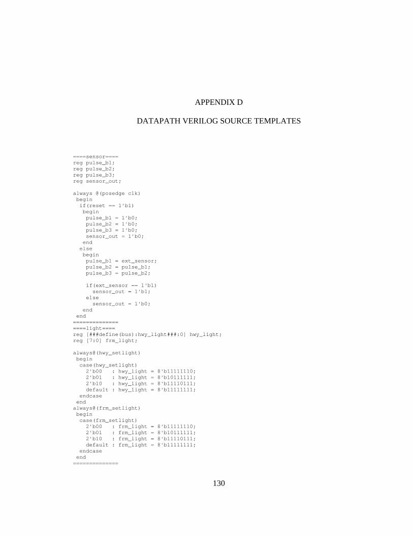
130
APPENDIX D
DATAPATH VERILOG SOURCE TEMPLATES
====sensor==== reg pulse_b1; reg pulse_b2; reg pulse_b3; reg sensor_out; always @(posedge clk) begin if(reset == 1'b1) begin pulse_b1 = 1'b0; pulse_b2 = 1'b0; pulse_b3 = 1'b0; sensor_out = 1'b0; end else begin pulse_b1 = ext_sensor; pulse_b2 = pulse_b1; pulse_b3 = pulse_b2; if(ext_sensor == 1'b1) sensor_out = 1'b1; else sensor_out = 1'b0; end end ============== ====light==== reg [###define(bus):hwy_light###:0] hwy_light; reg [7:0] frm_light; always@(hwy_setlight) begin case(hwy_setlight) 2'b00 : hwy_light = 8'b11111110; 2'b01 : hwy_light = 8'b10111111; 2'b10 : hwy_light = 8'b11110111; default : hwy_light = 8'b11111111; endcase end always@(frm_setlight) begin case(frm_setlight) 2'b00 : frm_light = 8'b11111110; 2'b01 : frm_light = 8'b10111111; 2'b10 : frm_light = 8'b11110111; default : frm_light = 8'b11111111; endcase end ==============

131
====display==== assign leds_out = {7'b0,active}; assign hex3 = digit3[6:0]; assign hex2 = digit2[6:0]; assign hex1 = digit1[6:0]; assign hex0 = digit0[6:0]; ============== ====timer==== wire start; reg enable; reg [5:0] timervalue; reg [5:0] timervalue2; reg [5:0] seconds; reg [25:0] count; reg timeout; reg active; reg [7:0] lower; reg [7:0] higher; reg [7:0] reflow; reg [7:0] refhigh; always@(posedge clk) begin if(reset == 1'b1) timervalue2 = 6'b0; else timervalue2 = timervalue; end always@(posedge clk) begin if(reset == 1'b1) timervalue = 6'b0; else timervalue = settimer; end assign start = (timervalue != settimer) ? 1'b1 : 1'b0; always@(posedge clk or posedge reset) begin if(reset == 1'b1) enable = 1'b0; else if(start == 1'b1) enable = 1'b1; else if(seconds == settimer) enable = 1'b0; end always@(reset or start or seconds[0]) begin if(reset == 1'b1 || start == 1'b1) begin timeout = 1'b0; end else if(seconds == settimer) begin timeout = 1'b1; end end
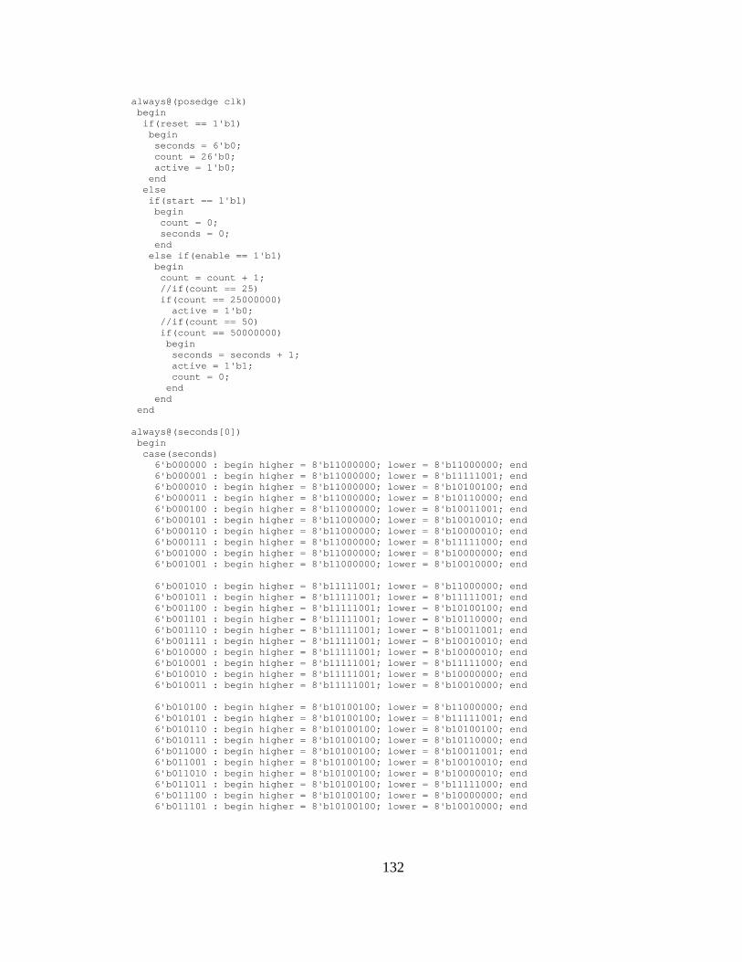
132
always@(posedge clk) begin if(reset == 1'b1) begin seconds = 6'b0; count = 26'b0; active = 1'b0; end else if(start == 1'b1) begin count = 0; seconds = 0; end else if(enable == 1'b1) begin count = count + 1; //if(count == 25) if(count == 25000000) active = 1'b0; //if(count == 50) if(count == 50000000) begin seconds = seconds + 1; active = 1'b1; count = 0; end end end always@(seconds[0]) begin case(seconds) 6'b000000 : begin higher = 8'b11000000; lower = 8'b11000000; end 6'b000001 : begin higher = 8'b11000000; lower = 8'b11111001; end 6'b000010 : begin higher = 8'b11000000; lower = 8'b10100100; end 6'b000011 : begin higher = 8'b11000000; lower = 8'b10110000; end 6'b000100 : begin higher = 8'b11000000; lower = 8'b10011001; end 6'b000101 : begin higher = 8'b11000000; lower = 8'b10010010; end 6'b000110 : begin higher = 8'b11000000; lower = 8'b10000010; end 6'b000111 : begin higher = 8'b11000000; lower = 8'b11111000; end 6'b001000 : begin higher = 8'b11000000; lower = 8'b10000000; end 6'b001001 : begin higher = 8'b11000000; lower = 8'b10010000; end 6'b001010 : begin higher = 8'b11111001; lower = 8'b11000000; end 6'b001011 : begin higher = 8'b11111001; lower = 8'b11111001; end 6'b001100 : begin higher = 8'b11111001; lower = 8'b10100100; end 6'b001101 : begin higher = 8'b11111001; lower = 8'b10110000; end 6'b001110 : begin higher = 8'b11111001; lower = 8'b10011001; end 6'b001111 : begin higher = 8'b11111001; lower = 8'b10010010; end 6'b010000 : begin higher = 8'b11111001; lower = 8'b10000010; end 6'b010001 : begin higher = 8'b11111001; lower = 8'b11111000; end 6'b010010 : begin higher = 8'b11111001; lower = 8'b10000000; end 6'b010011 : begin higher = 8'b11111001; lower = 8'b10010000; end 6'b010100 : begin higher = 8'b10100100; lower = 8'b11000000; end 6'b010101 : begin higher = 8'b10100100; lower = 8'b11111001; end 6'b010110 : begin higher = 8'b10100100; lower = 8'b10100100; end 6'b010111 : begin higher = 8'b10100100; lower = 8'b10110000; end 6'b011000 : begin higher = 8'b10100100; lower = 8'b10011001; end 6'b011001 : begin higher = 8'b10100100; lower = 8'b10010010; end 6'b011010 : begin higher = 8'b10100100; lower = 8'b10000010; end 6'b011011 : begin higher = 8'b10100100; lower = 8'b11111000; end 6'b011100 : begin higher = 8'b10100100; lower = 8'b10000000; end 6'b011101 : begin higher = 8'b10100100; lower = 8'b10010000; end

133
6'b011110 : begin higher = 8'b10110000; lower = 8'b11000000; end 6'b011111 : begin higher = 8'b10110000; lower = 8'b11111001; end 6'b100000 : begin higher = 8'b10110000; lower = 8'b10100100; end 6'b100001 : begin higher = 8'b10110000; lower = 8'b10110000; end 6'b100010 : begin higher = 8'b10110000; lower = 8'b10011001; end 6'b100011 : begin higher = 8'b10110000; lower = 8'b10010010; end 6'b100100 : begin higher = 8'b10110000; lower = 8'b10000010; end 6'b100101 : begin higher = 8'b10110000; lower = 8'b11111000; end 6'b100110 : begin higher = 8'b10110000; lower = 8'b10000000; end 6'b100111 : begin higher = 8'b10110000; lower = 8'b10010000; end 6'b101000 : begin higher = 8'b10011001; lower = 8'b11000000; end 6'b101001 : begin higher = 8'b10011001; lower = 8'b11111001; end 6'b101010 : begin higher = 8'b10011001; lower = 8'b10100100; end 6'b101011 : begin higher = 8'b10011001; lower = 8'b10110000; end 6'b101100 : begin higher = 8'b10011001; lower = 8'b10011001; end 6'b101101 : begin higher = 8'b10011001; lower = 8'b10010010; end 6'b101110 : begin higher = 8'b10011001; lower = 8'b10000010; end 6'b101111 : begin higher = 8'b10011001; lower = 8'b11111000; end 6'b110000 : begin higher = 8'b10011001; lower = 8'b10000000; end 6'b110001 : begin higher = 8'b10011001; lower = 8'b10010000; end 6'b110010 : begin higher = 8'b10010010; lower = 8'b11000000; end default : begin higher = 8'b11111111; lower = 8'b11111111; end endcase end always@(settimer[0]) begin case(settimer) 6'b000000 : begin refhigh = 8'b11000000; reflow = 8'b11000000; end 6'b000001 : begin refhigh = 8'b11000000; reflow = 8'b11111001; end 6'b000010 : begin refhigh = 8'b11000000; reflow = 8'b10100100; end 6'b000011 : begin refhigh = 8'b11000000; reflow = 8'b10110000; end 6'b000100 : begin refhigh = 8'b11000000; reflow = 8'b10011001; end 6'b000101 : begin refhigh = 8'b11000000; reflow = 8'b10010010; end 6'b000110 : begin refhigh = 8'b11000000; reflow = 8'b10000010; end 6'b000111 : begin refhigh = 8'b11000000; reflow = 8'b11111000; end 6'b001000 : begin refhigh = 8'b11000000; reflow = 8'b10000000; end 6'b001001 : begin refhigh = 8'b11000000; reflow = 8'b10010000; end 6'b001010 : begin refhigh = 8'b11111001; reflow = 8'b11000000; end 6'b001011 : begin refhigh = 8'b11111001; reflow = 8'b11111001; end 6'b001100 : begin refhigh = 8'b11111001; reflow = 8'b10100100; end 6'b001101 : begin refhigh = 8'b11111001; reflow = 8'b10110000; end 6'b001110 : begin refhigh = 8'b11111001; reflow = 8'b10011001; end 6'b001111 : begin refhigh = 8'b11111001; reflow = 8'b10010010; end 6'b010000 : begin refhigh = 8'b11111001; reflow = 8'b10000010; end 6'b010001 : begin refhigh = 8'b11111001; reflow = 8'b11111000; end 6'b010010 : begin refhigh = 8'b11111001; reflow = 8'b10000000; end 6'b010011 : begin refhigh = 8'b11111001; reflow = 8'b10010000; end 6'b010100 : begin refhigh = 8'b10100100; reflow = 8'b11000000; end 6'b010101 : begin refhigh = 8'b10100100; reflow = 8'b11111001; end 6'b010110 : begin refhigh = 8'b10100100; reflow = 8'b10100100; end 6'b010111 : begin refhigh = 8'b10100100; reflow = 8'b10110000; end 6'b011000 : begin refhigh = 8'b10100100; reflow = 8'b10011001; end 6'b011001 : begin refhigh = 8'b10100100; reflow = 8'b10010010; end 6'b011010 : begin refhigh = 8'b10100100; reflow = 8'b10000010; end 6'b011011 : begin refhigh = 8'b10100100; reflow = 8'b11111000; end 6'b011100 : begin refhigh = 8'b10100100; reflow = 8'b10000000; end 6'b011101 : begin refhigh = 8'b10100100; reflow = 8'b10010000; end 6'b011110 : begin refhigh = 8'b10110000; reflow = 8'b11000000; end 6'b011111 : begin refhigh = 8'b10110000; reflow = 8'b11111001; end 6'b100000 : begin refhigh = 8'b10110000; reflow = 8'b10100100; end 6'b100001 : begin refhigh = 8'b10110000; reflow = 8'b10110000; end
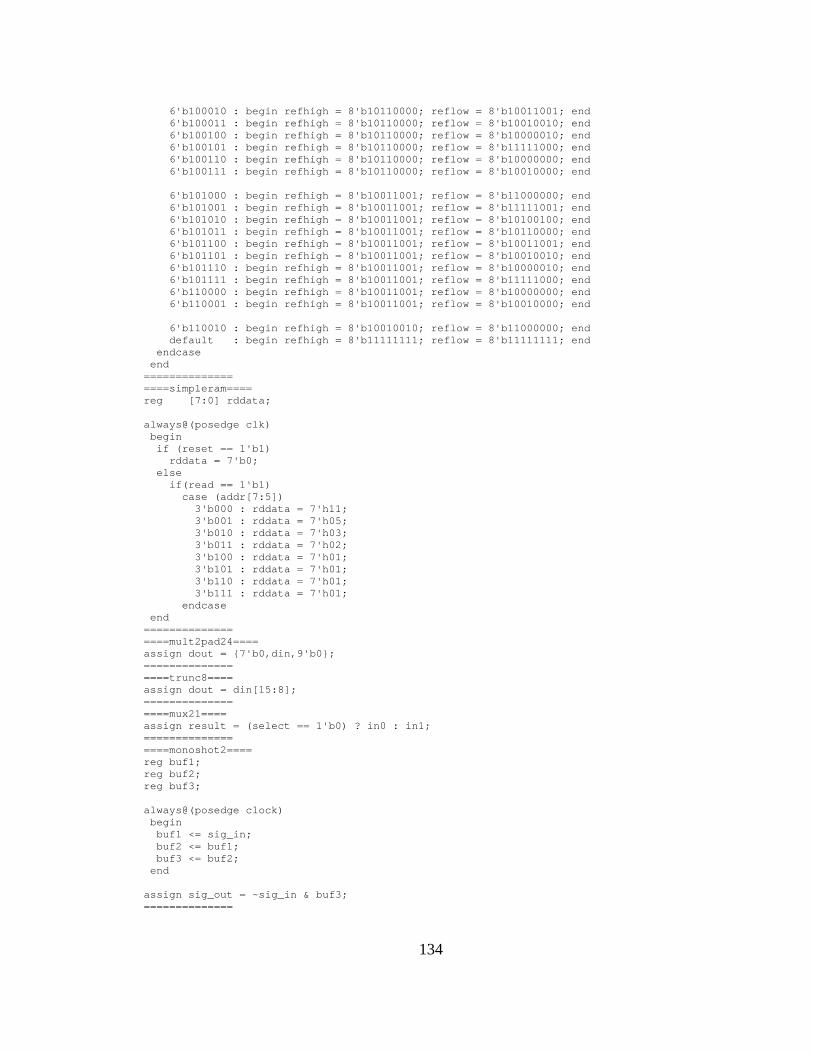
134
6'b100010 : begin refhigh = 8'b10110000; reflow = 8'b10011001; end 6'b100011 : begin refhigh = 8'b10110000; reflow = 8'b10010010; end 6'b100100 : begin refhigh = 8'b10110000; reflow = 8'b10000010; end 6'b100101 : begin refhigh = 8'b10110000; reflow = 8'b11111000; end 6'b100110 : begin refhigh = 8'b10110000; reflow = 8'b10000000; end 6'b100111 : begin refhigh = 8'b10110000; reflow = 8'b10010000; end 6'b101000 : begin refhigh = 8'b10011001; reflow = 8'b11000000; end 6'b101001 : begin refhigh = 8'b10011001; reflow = 8'b11111001; end 6'b101010 : begin refhigh = 8'b10011001; reflow = 8'b10100100; end 6'b101011 : begin refhigh = 8'b10011001; reflow = 8'b10110000; end 6'b101100 : begin refhigh = 8'b10011001; reflow = 8'b10011001; end 6'b101101 : begin refhigh = 8'b10011001; reflow = 8'b10010010; end 6'b101110 : begin refhigh = 8'b10011001; reflow = 8'b10000010; end 6'b101111 : begin refhigh = 8'b10011001; reflow = 8'b11111000; end 6'b110000 : begin refhigh = 8'b10011001; reflow = 8'b10000000; end 6'b110001 : begin refhigh = 8'b10011001; reflow = 8'b10010000; end 6'b110010 : begin refhigh = 8'b10010010; reflow = 8'b11000000; end default : begin refhigh = 8'b11111111; reflow = 8'b11111111; end endcase end ============== ====simpleram==== reg [7:0] rddata; always@(posedge clk) begin if (reset == 1'b1) rddata = 7'b0; else if(read == 1'b1) case (addr[7:5]) 3'b000 : rddata = 7'h11; 3'b001 : rddata = 7'h05; 3'b010 : rddata = 7'h03; 3'b011 : rddata = 7'h02; 3'b100 : rddata = 7'h01; 3'b101 : rddata = 7'h01; 3'b110 : rddata = 7'h01; 3'b111 : rddata = 7'h01; endcase end ============== ====mult2pad24==== assign dout = {7'b0,din,9'b0}; ============== ====trunc8==== assign dout = din[15:8]; ============== ====mux21==== assign result = (select == 1'b0) ? in0 : in1; ============== ====monoshot2==== reg buf1; reg buf2; reg buf3; always@(posedge clock) begin buf1 <= sig_in; buf2 <= buf1; buf3 <= buf2; end assign sig_out = ~sig_in & buf3; ==============

135
====mult_pipe2==== // reg [###define(bus):result###:0] buffer; // reg [###define(bus):result###:0] result; // always@(posedge clock) // begin // if (aclr == 1'b1) // begin // buffer <= ###define(width):result###'b0; // result <= ###define(width):result###'b0; // end // else // begin // buffer <= dataa * datab; // result <= buffer; // end // end //BBsynplify lpm_mult mult ( //BBsynplify .clock(clock), //BBsynplify .aclr(aclr), //BBsynplify .dataa(dataa), //BBsynplify .datab(datab), //BBsynplify .result(result)); //BBsynplify defparam mult.LPM_WIDTHA = ###define(width):dataa###; //BBsynplify defparam mult.LPM_WIDTHB = ###define(width):datab###; //BBsynplify defparam mult.LPM_WIDTHP = ###define(width):result###; //BBsynplify defparam mult.LPM_WIDTHS = ###define(width):dataa###; //BBsynplify defparam mult.LPM_PIPELINE = 2; ============== ====dflipflop==== // reg [###define(bus):q###:0] q; // // always@(posedge clock) // begin // if (aclr == 1'b1) // q <= ###define(width):q###'b0; // else // if (enable == 1'b1) // q <= data; // end //BBsynplify lpm_dff dff ( //BBsynplify .data (data), //BBsynplify .clock(clock), //BBsynplify .enable(enable), //BBsynplify .aclr(aclr), //BBsynplify .q (q)); //BBsynplify defparam dff.LPM_WIDTH = ###define(width):data###; ==============

136
====counter==== // reg [###define(bus):q###:0] q; // // always@(posedge clock) // begin // if (aclr == 1'b1 | sclr == 1'b1) // q <= ###define(width):q###'b0; // else // if(cnt_en == 1'b1) // q <= q + 1; // end //BBsynplify lpm_counter counter ( //BBsynplify .clock(clock), //BBsynplify .aclr(aclr), //BBsynplify .sclr(sclr), //BBsynplify .cnt_en(cnt_en), //BBsynplify .q(q)); //BBsynplify defparam counter.LPM_WIDTH = ###define(width):q###; ============== ====comparator==== // assign aeb = (dataa == datab) ? 1'b1 : 1'b0; //BBsynplify lpm_compare comparator ( //BBsynplify .dataa(dataa), //BBsynplify .datab(datab), //BBsynplify .aeb(aeb)); //BBsynplify defparam comparator.LPM_WIDTH = ###define(width):dataa###; ============== ====subtract_pipe1==== // reg [###define(bus):result###:0] result; // // always@(posedge clock) // begin // if (aclr == 1'b1) // result <= ###define(width):result###'b0; // else // result <= dataa - datab; // end //BBsynplify lpm_add_sub subtract_pipe1 ( //BBsynplify .clock(clock), //BBsynplify .aclr(aclr), //BBsynplify .dataa(dataa), //BBsynplify .datab(datab), //BBsynplify .result(result)); //BBsynplify defparam subtract_pipe1.LPM_WIDTH = ###define(width):dataa###; //BBsynplify defparam subtract_pipe1.LPM_DIRECTION = "SUB"; //BBsynplify defparam subtract_pipe1.LPM_PIPELINE = 1; ============== ====adder==== //BBsynplify lpm_add_sub adder ( //BBsynplify .dataa(dataa), //BBsynplify .datab(datab), //BBsynplify .result(result)); //BBsynplify defparam adder.LPM_WIDTH = ###define(width):dataa###; //BBsynplify defparam adder.LPM_DIRECTION = "ADD"; ==============
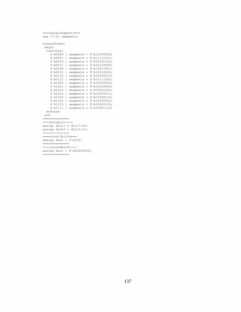
137
====sevensegment==== reg [7:0] segments; always@(hex) begin case(hex) 4'b0000 : segments = 8'b11000000; 4'b0001 : segments = 8'b11111001; 4'b0010 : segments = 8'b10100100; 4'b0011 : segments = 8'b10110000; 4'b0100 : segments = 8'b10011001; 4'b0101 : segments = 8'b10010010; 4'b0110 : segments = 8'b10000010; 4'b0111 : segments = 8'b11111000; 4'b1000 : segments = 8'b10000000; 4'b1001 : segments = 8'b10010000; 4'b1010 : segments = 8'b10001000; 4'b1011 : segments = 8'b10000011; 4'b1100 : segments = 8'b11000110; 4'b1101 : segments = 8'b10100001; 4'b1110 : segments = 8'b10000110; 4'b1111 : segments = 8'b10001110; endcase end ============== ====bussplit==== assign dout1 = din[7:4]; assign dout2 = din[3:0]; ============== ====const3bit5==== assign dout = 3'b101; ============== ====const8bit0==== assign dout = 8'b00000000; ==============
138
REFERENCES
[1] A.A. Jerraya and W. Wolf, “Hardware/Software Interface Codesign for Embedded Systems”, Computer, vol. 38, 2005.
[2] F. Coyle and M. Thornton, “From UML to HDL: a Model Driven Architectural Approach to
Hardware-Software Co-Design”, Proceedings of the Information Systems: New Generations Conference (ISNG), April 4-6, 2005, pp. 88-93.
Available: http://engr.smu.edu/~mitch/ftp_dir/SRC/isng05.pdf [3] “OMG Model Driven Architecture” Home Page, Object Management Group, Inc. Available: http://www.omg.org/mda/ [4] R. Damasevicius and V. Stuikys, “Application of UML for hardware design based on design
process model”, Proc. of Design Automation Conference (ASP-DAC), 27-30 January 2004, pp. 244-249.
[5] W.E. McUmber and B.H.C. Cheng, “UML-based analysis of embedded systems using a mapping
to VHDL”, Proc. of IEEE International Symposium on High Assurance Software Engineering (HASE’99), November 1999, pp. 56-63.
[6] L.M. Reyneri, “An Object Oriented Codesign Flow for low-cost HW/SW/mixed-signal systems
based on UML”, Proc. of IEEE Mediterranean Electrotechnical Conference (MELECON), 16-19 May 2006, pp. 80-84.
[7] D. Bjarklund and J. Lilius, “From UML behavioral descriptions to efficient synthesizable VHDL”,
Proc. of 20th IEEE NORCHIP Conference, 11-12 November 2002. [8] D.S. Frankel, Model Driven Architecture: Applying MDA to Enterprise Computing, Wiley
Publishing, Inc.:Indianapolis, IN, 2003. [9] “Introduction to OMG’s Unified Modeling Language (UML)”, Object Management Group, Inc. Available: http://www.omg.org/gettingstarted/what_is_uml.htm [10] Rational Rose Software Family Overview, IBM Corporation.
Available: http://www-306.ibm.com/software/awdtools/developer/rose/index.html [11] Rhapsody Software Overview, I-Logix/Telelogic Corporation. Available: http://www.ilogix.com/sublevel.aspx?id=53 [12] “Extensible Markup Language (XML)” Home Page, World Wide Web Consortium (W3C). Available: http://www.w3.org/XML/ [13] “XML Tutorial”, W3C Schools. Available: http://www.w3schools.com/xml/default.asp

139
[14] M. Fitzgerald, Learning XSLT, 1st edition, O’Reilly Media, Inc: Sebastopol, CA, 2003. [15] S. Brown and Z. Vranesic, Fundamentals of Digital Logic with Verilog Design, McGraw-
Hill:New York, NY, 2003. [16] Synplify Pro Software Datasheet, Synplicity, Inc. Available: http://www.synplicity.com/literature/pdf/syn_pro_ds.pdf [17] R.B. Reese and M.A. Thornton, Introduction to Logic Synthesis using Verilog HDL, Morgan &
Claypool Publishers, 2006. [18] Quartus-II Web Edition Software, Altera Corporation. Available: http://www.altera.com/products/software/products/quartus2web/sof-quarwebmain.html [19] ISE WebPACK Software, Xilinx, Inc. Available: http://www.xilinx.com/ise/logic_design_prod/webpack.htm [20] E.F. Moore, “Gedanken experiments on sequential machines,” Automata Studies, Princeton
University Press:Princeton, NJ, pp. 129-153, 1956. [21] G.H. Mealy, “A method for synthesizing sequential circuits,” Bell System Technical Journal, Vol.
34, No. 5, pp. 1045-1079, 1955. [22] R. Schwartz, T. Phoenix, and B. Foy, Learning Perl, 4th edition, O’Reilly Media, Inc: Sebastopol,
CA, 2005. [23] L. Li, M. Thornton, and F. Coyle, “Automatic High Level Assertion Generation and Synthesis for
Embedded System Design”, Unpublished White Paper on SystemVerilog Assertions, April 2006. Available: http://engr.smu.edu/~mitch/ftp_dir/SRC/SVA_assertions.pdf [24] The Apache Xalan Project. Available: http://xalan.apache.org/ [25] John K. Ousterhout, Tcl and the Tk Toolkit, Addison-Wesley, Reading, MA, USA, ISBN 0-201-
63337-X, 1994. [26] Quartus-II Scripting Reference Manual, Altera Corporation. Available: http://www.altera.com/literature/manual/TclScriptRefMnl.pdf [27] “Xilinx ISE 8 Software Manuals and Help – PDF Collection,” Xilinx Corporation, 2005.
Available: http://toolbox.xilinx.com/docsan/xilinx8/books/manuals.pdf [28] R.J. Auburn, J. Barnett, M. Bodell, and T.V. Raman, “State Chart XML (SCXML): State
Machine Notation for Control Abstraction 1.0,” W3C Working Draft 5, July 2005. Available: http://www.w3.org/TR/2005/WD-scxml-20050705/

140
[29] OMG Systems Modeling Language (OMG SysML) Specification, Final Adopted Specification, May 2006.
[30] M.-C.V. Marinescu and M. Rinard, “High-level automatic pipelining for sequential circuits”,
Proc. of 14th International Symposium on System Synthesis, 2001, pp. 215-220.


