
An Application-Specific Design Methodology for STbus Crossbar Generation
Author: Srinivasan Murali, Giovanni De MicheliProceedings of the DATE’05,pp.1176-1181,2005
Presenter : Ching-Yuan Lin
Date : 2007/1/22
Seminar book :P120
2
Abstract As the communication requirements of current and future Multiprocesso
r Systems on Chips (MPSoCs) continue to increase, scalable communication architectures are needed to support the heavy communication demands of the system. This is reflected in the recent trend that many of the standard bus products such as STbus, have now introduced the capability of designing a crossbar with multiple buses operating in parallel. The crossbar configuration should be designed to closely match the application traffic characteristics and performance requirements. In this work we address this issue of application-specific design of optimal crossbar (using STbus crossbar architecture), satisfying the performance requirements of the application and optimal binding of cores onto the crossbar resources. We present a simulation based design approach that is based on analysis of actual traffic trace of the application, considering local variations in traffic rates, temporal overlap among traffic streams and criticality of traffic streams. Our methodology is applied to several MPSoC designs and the resulting crossbar platforms are validated for performance by cycle-accurate SystemC simulation of the designs. The experimental case studies show large reduction in packet latencies (up to 7×) and large crossbar component savings (up to 3.5×) compared to traditional design approaches.

3
STbus Crossbar Architecture
Low-latency, high bandwidth infrastructure Interface components: arbiters and frequency/data width adapters
I1
I2
I3
A1
A2
A3
Bus 1
Bus 2
Bus 3
T1
T2
T3
InitiatorsTargetsArbiters Buses
I1
I2
I3
A1
A2
A3
Bus 1
Bus 2
Bus 3
T1
T2
T3
InitiatorsTargetsArbitersBuses
Initiator-Target crossbar Target-Initiator crossbar
I1
I2
I3
A1
A2
Bus 1
Bus 2
T1
T2
T3
Initiators TargetsArbiters Buses
Initiator-Target crossbar
※Full crossbar architecture
※Partial crossbar architecture
4
What’s the Problem Full crossbar is expensive
Lot of wires and gates Partial crossbar is a compromise solution
Optimum partial crossbar Latency close to full crossbar Fewer component and area How to design best partial crossbar for applications?
5
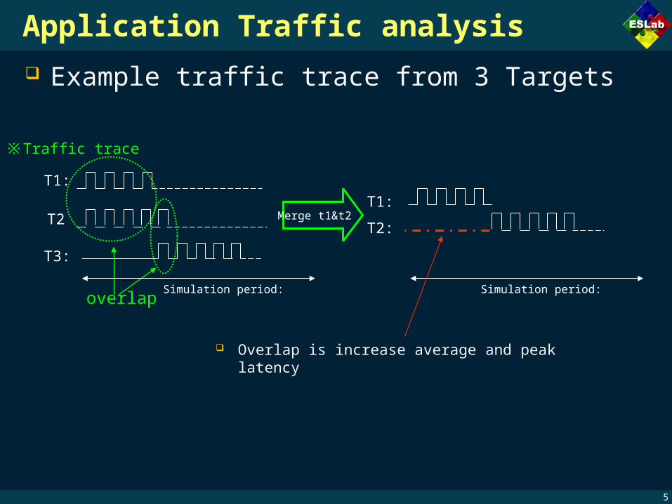
Application Traffic analysis Example traffic trace from 3 Targets
※Traffic trace
Merge t1&t2
T1:
T2
T3:
overlapSimulation period:
Overlap is increase average and peak latency
T1:
T2:
Simulation period:

6
Consider criticality of streams Targets with overlapping real-time stream should not share the sa
me bus
※Traffic trace
T1:
T2
T3:
Simulation period:
Real time constraint

7
Crossbar design approach Simulation time window for analysis
Split to fixed sized windows
In each simulation window Satisfy bandwidth requirement
The total receives data of every core (place on same bus) must less or equal than window size
Minimize overlaps among streams Consider criticality of streams
T1:
T2
T3:
overlapSimulation period:
Windows 1 Windows 2

8
Design flow for partial crossbar design
9
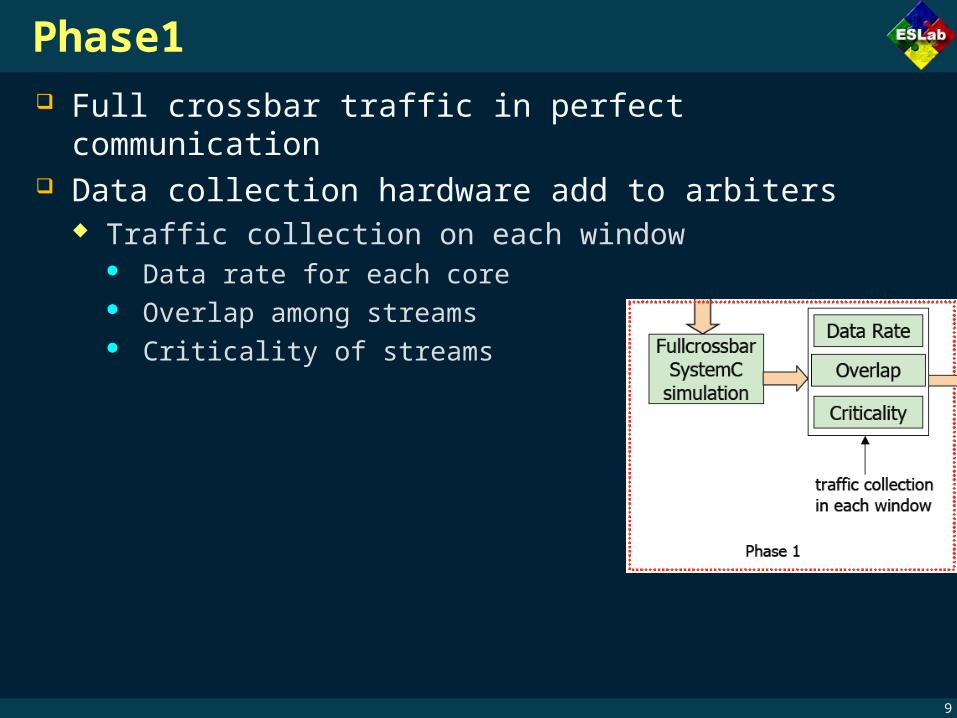
Phase1 Full crossbar traffic in perfect communication Data collection hardware add to arbiters
Traffic collection on each window Data rate for each core Overlap among streams Criticality of streams
10
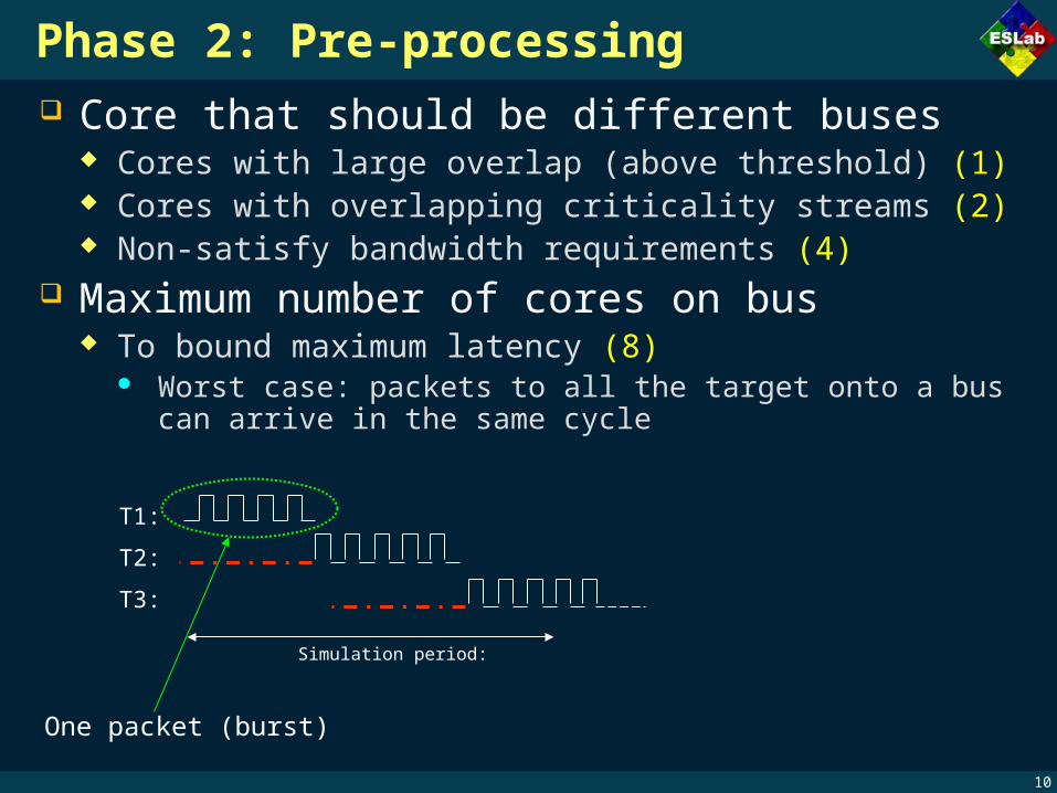
Phase 2: Pre-processing Core that should be different buses
Cores with large overlap (above threshold) (1) Cores with overlapping criticality streams (2) Non-satisfy bandwidth requirements (4)
Maximum number of cores on bus To bound maximum latency (8)
Worst case: packets to all the target onto a bus can arrive in the same cycle
T1:
T2:
Simulation period:
T3:
One packet (burst)
11
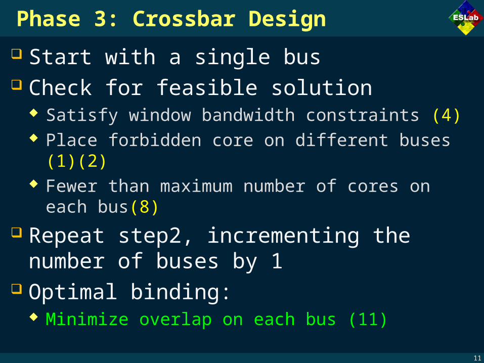
Phase 3: Crossbar Design
Start with a single bus Check for feasible solution
Satisfy window bandwidth constraints (4) Place forbidden core on different buses (1)(2) Fewer than maximum number of cores on each bus(8)
Repeat step2, incrementing the number of buses by 1
Optimal binding: Minimize overlap on each bus (11)

12
Experiment result Application benchmark
Matrix suite-1 (25 cores) Matrix suite-2 (21 cores) FFT suite (29 cores) Quick sort suite (15 cores) DES encryption system
(19 cores)
※Matrix multiplication benchmark-2 (21 cores)
Initiator-target full crossbar Need 12 bus
Target-initiator full crossbar Need 9 bus
FC bus count = 21

13
The average and maximum packet latencies
Win : optimal partial crossbar Avg: crossbar base communication traffic flow ,by relaxing overlap constraints and using a single window
Latencies of crossbar (avg) are 4x to 7x higher than crossbar designed using our scheme
14
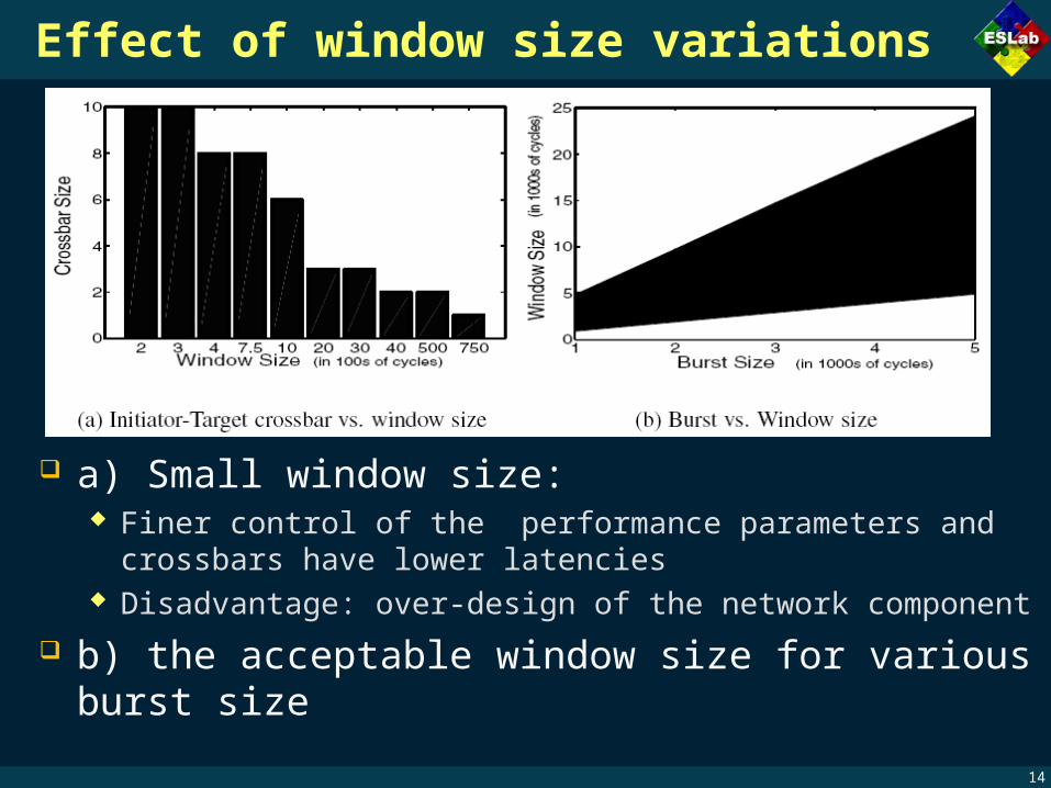
Effect of window size variations
a) Small window size: Finer control of the performance parameters and crossbars
have lower latencies Disadvantage: over-design of the network component
b) the acceptable window size for various burst size

15
Overlap threshold setting
From experiments, threshold value can be set: 30%-40% of window size for conservative design 10% of window size for conservative designs

16
Conclusion Presented methodology for STbus crossbar design
local variations in traffic Overlap of streams Criticality of traffic streams
Large saving in components, good performance Approach can be extended to other bus designs


