
Ambiance CLX Electric Series AL45CLX • AL60CLX • AL80CLX • AL100CLX • AL144CLX
INSTALLATION/SERVICE INSTRUCTIONS FOR USE IN UNITED STATES AND CANDA

2
USER INSTRUCTIONS
Read these instructions completely before beginning installation. Failure to follow them could cause a heater malfunction resulting in serious injury and/or property damage.
WARNING: All electric heaters have hot and arcing or sparking parts inside. Do not use it in areas where gasoline, paint or flammable liquids are or are stored.
This fireplace meets the construction and safety standards of H.U.D. for application in manufactured homes when installed according to these instructions.
INSTALLER: Leave this manual with the appliance. CONSUMER: Retain this manual for future reference.

3
TABLE OF CONTENTS
Important Instructions .................................. 3 Power Data ................................................. 4 Product Dimensions .................................... 4 Box Contents ............................................... 5 Unpacking and Testing ................................ 6 Locating Fireplace ....................................... 6 Installation .................................................... 7
When using electrical heaters, basic precau-tions should always be followed to reduce the risk of fire, electric shock and injury to persons, including the following:
1. Read all instructions before installing or using this heater. 2. This heater is hot when in use. To avoid burns, do not let bare skin touch hot surfaces. Keep combustible materials, such as furniture, pillows, bedding, papers, clothes, and curtains at least 3 feet (0.9m) from the front of the heater and keep them away from the sides and rear. 3. Extreme caution is necessary when any heater is used by or near children or invalids and whenever the heater is left operating and unattended. 4. Do not operate any heater after it malfunctions. Disconnect power at service panel and have heater inspected by a reputable electrician before using. 5. Do not use outdoors. 6. To disconnect heater, turn controls to off and turn off power to heater circuit at main disconnect panel. 7. Do not insert or allow foreign objects to enter any ventilation or exhaust opening as this may cause an electric shock or fire, or damage the heater. 8. To prevent a possible fire, do not block air intakes or exhaust in any manner. 9. A heater has hot and arcing or sparking parts inside. Do not use it in areas where gasoline, paint or flammable vapors or liquids are used or stored. 10. Use this heater only as described in this manual. Any other use not recommended by the manufacturer may cause fire, electric shock or injury to persons. 11. This heater includes a visual alarm to warn that parts of the heater are getting excessively hot. If the alarm illuminates, immediately turn
WARNING: Improper installation, adjust-ment, alteration, service or maintenance can cause injury or property damage. Re-fer to this manual. For assistance or ad-ditional information, consult a qualified installer.
CAUTION: Do not expose the heater to the elements (such as rain, etc).
Do not place clothing or other flammable material on or near firebox. Never place any objects on the fireplace.
Carefully supervise young children when they are in the room with fireplace.
Fireplace becomes very hot when run-ning. Keep children and adults away from hot surfaces to avoid burns or clothing ignition. Fireplace will remain hot for a time after shutdown. Allow sur-faces to cool before touching.
Do not install fireplace directly on carpet or similar surface which may restrict air circulation beneath unit.
Operation ................................................... 10 Service Parts .............................................. 12 Frequently Asked Questions ...................... 13 Troubleshooting ......................................... 14 Cleaning and Maintenance Instructions ..... 16 Wiring Diagram .......................................... 16
IMPORTANT INSTRUCTIONS
CAUTION: In order to avoid over-heating, do not cover the heater.
USER INSTRUCTIONS

4
USER INSTRUCTIONS USER INSTRUCTIONS
the heater off and inspect for any objects on or adjacent to the heater that may have blocked the airflow or otherwise caused high temperatures to have occurred. DO NOT OPERATE THE HEATER WITH THE ALARM ILLUMINATING. 12. Do not operate any heater with a damaged cord or plug or after the heater malfunctions, has been dropped or damaged in any manner. Return heater to authorized service facility for examination, electrical or mechanical adjustment, or repair. 13. This heater is not intended for use in bathrooms, laundry areas and similar indoor
locations. Never locate heater where it may fall into a bathtub or other water container. 14. Do not run cord under carpeting. Do not cover cord with throw rugs, runners, or the like. Arrange cord away from traffic area and where it will not be tripped over. 15. Avoid the use of an extension cord because the extension cord may overheat and cause a risk of fire. However, if you have to use an extension cord, the cord shall be No. 12 AWG minimum size and rated not less than 1875 watts. 16. SAVE THESE INSTRUCTIONS
IMPORTANT INSTRUCTIONS
POWER DATA
AL-100 CLX AL-60CLX AL-45 CLX AL-80 CLX AL-144 CLX
Volts/HZ Amps
AC 120V/60Hz 15 Amps
AC 120V/60Hz 15 Amps
AC 120V/60Hz 15 Amps
AC 120V/60Hz 15 Amps
AC 120V/60Hz 15 Amps
Heater AC 120V/60Hz
1500W AC 120V/60Hz
1500W AC 120V/60Hz
1500W AC 120V/60Hz
1500W AC 120V/60Hz
1500W
Lamps LED LED LED LED LED
Rotor motor AC 120V/60Hz 4W CCW 15/18
r/min
AC 120V/60Hz 4W CCW 15/18
r/min
AC 120V/60Hz 4W CCW 15/18
r/min
AC 120V/60Hz 4W CCW 15/18
r/min
AC 120V/60Hz 4W CCW 15/18
r/min
Shipping Size 102.5x9x31.5 in 62.5x9x31.5 in 47.5x9x31.5 in 82.5x9x31.5 in 146.5x9x31.5 in
Shipping Weight
194 lbs 99 lbs 66 lbs 150 lbs 279 lbs
PRODUCT DIMENSIONS
Width varies (see chart on next page)
25 1/2” (all models)
5 1/2” (all models)

5
BOX CONTENTS
1 Fire Unit
1 Glass Face
3 L-metal Brackets
4 Wall Anchors
4 Small Washer Head Screws
4 Large Washer Head Screws
1 Remote
1 Mounting Bracket
USER INSTRUCTIONS
Model Viewing Area Face Dimensions Firebox Dimensions
AL45CLX 27” W x 10” H 45” W x 25 1/2” H 29 1/4” W x 19 1/4” H x 5 1/2” D
AL60CLX 42” W x 10” H 60” W x 25 1/2” H 44 1/4” W x 19 1/4” H x 5 1/2” D
AL80CLX 62” W x 10” H 80” W x 25 1/2” H 64 1/4” W x 19 1/4” H x 5 1/2” D
AL100CLX 82” W x 10” H 100” W x 25 1/2” H 84 1/4” W x 19 1/4” H x 5 1/2” D
AL144CLX 126” W x 10” H 144” W x 25 1/2” H 130 3/4” W x 19 1/4” H x 5 1/2” D
Glacier Crystal Resin Coal

6
USER INSTRUCTIONS INSTALLATION
UNPACKING AND TESTING
This heater is for use on 120 volts. The cord has a plug as shown at A. An adapter as shown at C is available for connecting three-blade grounding-type plugs to two-slot recep-tacles. The green grounding lug extending from the adapter must be connected to a per-manent ground such as a properly grounded outlet box. The adapter should not be used if a three-slot grounded receptacle is available.
CAUTION: The unit's power supply cord must be connected to a properly ground-ed and protected 120-volt outlet. Always use ground fault protection where re-quired by the electrical code. Never use an extension cord with this product.
WARNING: Do not operate the unit if it is damaged or has malfunctioned. If you suspect the unit is damaged, return the unit to an authorized service facility for examination, electrical or mechanical ad-justment or repair.
LOCATING FIREPLACE
CAUTION: Do not locate in a moist room
such as a bathroom or laundry room.
CAUTION: Wear gloves and safety glass-es for protection during installation and
maintenance.
This electric fireplace can be installed framed in to a wall. Install at least 1 foot from the floor and 3 feet from any combustibles such as car-pet and drapes.
Recessed

7
INSTALLATION
WARNING - RISK OF FIRE! The power cord must not be pinched or against a sharp edge. Secure cord to avoid tripping or snagging to reduce the risk of fire, electric shock or personal in-
jury.
Do not run cord under carpeting. Do not cover cord with throw rugs, runners or the like. Arrange cord away from traffic areas and where it will not be tripped over.
WARNING - RISK OF FIRE! To prevent a possible fire, do not block air intake or exhaust in any manner. Do not use on soft surfaces where openings may become blocked.
WARNING - RISK OF FIRE! Do not blow or place insulation against the firebox.
To reduce the risk of fire do not store or use gasoline or other flammable vapors in the vicinity of this or any other heater.
Installing fireplace
Select a suitable location that is not suscep-tible to moisture and is a safe distance from drapes, furniture and high traffic areas. A qualified electrician should add an electrical outlet per local building codes. See shaded area on recessed installation diagram for proper outlet placement. Fireplace must be installed to a plumb vertical wall for cor-
rect operation of touch controls.
Note: Follow all national and local electrical codes. This fireplace can be framed in to the wall.
WARNING: If the information in these in-structions is not followed exactly, a fire or explosion may result causing property damage, personal injury or death.
INSTALLATION

8
INSTALLATION INSTALLATION
Recessed Installation: 1. Prepare frame opening according to chart. Frame opening is slightly larger than the fire unit. For best concealment, a qualified electrician should add an electrical outlet per local building codes anywhere in the shaded area. Install 110v outlet on the finished surface above or to the right of the recessed opening. Fascia will cover the plug and outlet.
3. Secure fire unit to the finished framed opening with the provided large washer head screws. Make certain that at least 4 of the screws are driven in to a solid backing.
AL45CLX 30” W x 19 3/4” H x 4” D
AL60CLX 45” W x 19 3/4” H x 4” D
AL80CLX 65” W x 19 3/4” H x 4” D
AL100CLX 85” W x 19 3/4” H x 4” D
AL144CLX 131 1/2” W x 19 3/4” H x 4” D
2. Attach L-metal brackets to the fire unit with he provided small washer head screws.
Fireplace will stand proud of the finished wall opening by 1-1/8 inches, this area must not be blocked by any additional trim, tile, etc. as this will block proper air flow. This is a semi-permanent installation. Remove screws to relocate.
4. Hang the face on the fire unit. Make certain that the hooks from the on the backside of the glass face are secured on all 4 studs on the fire unit.
Power cord
Power cord
Power cord

9
Wall-hung Installation: 1. Hang the mounting bracket with the included large washer head screws and wall anchors. Wall anchors should be used at the highest outside corners. Be certain that at least two screws are driven in to solid backing. Use the chart to see proper distance between the screws used to hold the mounting bracket.
2. Attach the L metal bracket to the bottom of the fire unit with the small washer head screws.
3. Hang the fire unit on the mounting bracket by slotting the key hole slots on the fire unit over the hooks on the mounting bracket.
4. Use the included L metal bracket to secure the bottom of the fire unit to the wall. This is a semi-permanent installation. Remove screws to relocate.
AL45CLX 27 3/4 inches
AL60CLX 29 3/4 inches
AL80CLX 49 3/4 inches
AL100CLX 69 inches
AL144CLX 113 inches
Use the chart below to see proper distance between the screws used to hold the mount-ing bracket.
5. Hang the glass face on the fire unit. Make certain that the hooks from the on the backside of the glass face are secured on all 4 studs on the fire unit.
INSTALLATION
Power cord
Power cord
Screw holes

10
OPERATION OPERATION
OPERATION
On the bottom of the unit is a main power switch. Switch this to the on position to begin using the fireplace. Directly below the flame, on the right hand side are 3 small LED status lights, as well as function controls and a digital temperature readout.
When all indicator lights are off, pressing on any button will only show the status. Once the indicator lights are on you can touch any func-tion button to control the fireplace. Touch the power button to turn the machine on. This will be indicated by 1 orange LED light. Touch the Heater button once to turn the heater on low, and touch again to turn the heater to high. The Backlight button dims the flame image from high, medium, low and off in that order.
Power
When the switch turns on, this orange pilot lamp is always on. It shows the fire is ener-
gized.
The status light above shows that the power is on and the heater is on low
The status light above shows that the power is on and the heater is on high
Heater
Backlight
To use the built in digital thermostat, start by set-ting the heat to high or low. You may now set the temperature limit by using the up or down arrows. After selecting the set temperature, the arrows will fade and the ambient room temperature will be dis-played. The heater will energize when the room temperature is below the set temperature, and will continue to function automatically until turned off by touching the Heater function on the glass face or remote control. See the FAQ for instructions to tog-gle the device to Fahrenheit or Celsius.
The digital control may be unplugged from the touch control for manual operation. The fea-tures will be off, low heat or high heat.

11
OPERATION
Remote operation: To turn on the remote control, long press the Power button until the display turns on (long pressing the Power button while the remote is on will turn off the remote). Powering on the remote will bring you to the home screen (pictured on the right). Use the Navigation buttons to highlight the desired control menu and press Enter. The remote control comes with a lithium-ion rechargeable battery and can be charged with the included Micro USB charger. When the fireplace is in standby mode, pressing the red Power button will turn the fire image on to the brightest setting. Press the power button again to turn the fire image (and heater, if heater is on) to the standby or off condition.
Pressing Enter while this icon is highlighted will bring you to the Flame control menu. Pressing down on the Navigation Ring will decrease the brightness of the flame then turn off the flame. Pressing up on the Navigation Ring will increase the brightness of the flame. Pressing right on the Navigation Ring will toggle the color of the flame from orange to blue. Pressing the Home button or the left button will bring you to the home screen.
Pressing Enter while this icon is highlighted will bring you to the Temperature control menu. Pressing up will turn the heater to high heat. Pressing down will turn the heater to low heat, long press down to turn the heater off. Pressing right will enable the thermostat sub-menu. Use the up and down buttons to select the set temperature (displayed on the face of the fireplace). Pressing the Home button or the left button will bring you to the home screen.
If your fireplace is equipped with the optional RGB halo light, pressing Enter while this icon is highlighted will bring you to the Feature control menu. Pressing Enter to turn on or turn off the halo light. Pressing up or down on the Navigation Ring will increase or decrease the brightness. Pressing right will change the color. Pressing the Home button or the left button will bring you to the home screen.
Pressing Enter while this icon is highlighted will bring you to the Information menu. Displayed in this menu will be the model name, features installed and whether the device reads in Fahrenheit or Celsius. See the FAQ for instructions to toggle the remote Fahrenheit or Celsius.
Home
Battery Indicator
Flame control
Temperature control
Charge port
Color control
Information
Navigation Ring
Power
Enter

12
MAINTENANCE MAINTENANCE
AL CLX SERVICE PARTS
ITEM PHOTO COMMENTS
MFPCB1 PRINTED CIRCUIT BOARD CONTROLS LOW VOLTAGE AND HIGH VOLTAGE FUNCTIONS
MFTC2 LCD TOUCH CONTROL
MFTTC2 LCD TEMPERATURE TOUCH CONTROL
MFRR1 REMOTE CONTROL IR RECEIVER
MF12VT1 TRANSFORMER
MFHF12015 HEATER FAN 120 V 1500 WATTS
MFPHF AL HEATER 120 V 1500 WATTS
MFSM120 SPINDLE MOTOR 120 V 50-60 HZ
MFP45 LED
LED LIGHT STRIP AL 45
MFP60 LED LED LIGHT STRIP AL 60
MFP80 LED LED LIGHT STRIP AL 80
MFP100 LED LED LIGHT STRIP AL 100
MFP144 LED LED LIGHT STRIP AL 144
MF PS1 POWER SWITCH
MFR1 REMOTE CONTROL

13
FREQUENTLY ASKED QUESTIONS
Q. How do you program the remote control? A. The remote comes pre-programmed, however to add features or toggle Fahrenheit/Celsius long
press the Power and Home buttons to bring up the program menu. Use the Enter key to select the device (AL_CLX), confirm the RGB halo light (in color is enabled, in black and white is disa-bled), and lastly select Fahrenheit or Celsius.
Q. How do you change the fire unit to Fahrenheit/Celsius? A. Long press on the up and down arrows on the fire unit to toggle between Fahrenheit and Celsius. On the remote control, select the I for information button and then the C or F button. Toggle with arrow to desired readout. Q. What distance can the remote be used from the fireplace? A. Optimal distance for the remote control is within 10 yards. Q. Can you turn on the fireplace via the touch screen and off via the remote (or vise versa)? A. Yes. Q. My touch screen will not operate properly. A. The fireplace must be installed to a plumb vertical wall for correct operation of touch controls. Re-move power source for 30 seconds to allow unit to reset. Attach glass face, turn on power and wait for indicator lights to turn off. Q. Low long will the LED lights last? A. LED Lamps have a life span of up to 20 years. Q. Can the sensitivity of the touch screen be adjusted? A. Yes, but only by the factory. Not just any technician will be able to adjust the touch screen sensi-tivity. Q. Can the fireplace be installed outside? A. No. Please review the entire safety chapter before installing this fireplace. Q. Does the fireplace need to be on a dedicated 15 amp circuit? A. Yes. Q. What thickness of sheetrock should be used for the recessed installation?
MAINTENANCE
AL45WMB
WALL MOUNT BRACKET AL45
AL60WMB WALL MOUNT BRACKET AL60
AL80WMB WALL MOUNT BRACKET AL80
AL100WMB WALL MOUNT BRACKET AL100
AL144WMB WALL MOUNT BRACKET AL144
ALGLS45 GLASS FACE AL45
ALGLS60 GLASS FACE AL60
ALGLS80 GLASS FACE AL80
ALGLS100 GLASS FACE AL100
ALGLS144 GLASS FACE AL144

14
TROUBLESHOOTING
PROBLEM POSSIBLE CAUSE CORRECTIVE ACTION
Flame is not visible when unit is turned on
A. Wiring is loose A. Disconnect unit from power source and inspect for loose connections
B. Motherboard is defective B. Replace motherboard
Fireplace lights up but there is no flame image
A. Wiring for motor is loose A. Disconnect unit from power source and inspect for loose connections from motor
B. Motor is defective B. Replace motor
Fireplace is squeaking when flame image is on
A. Fireplace spindle/ rod is contacting to metal
A. Apply lithium grease or any standard grease to contacts with rod and metal
B. Motor is defective B. Replace motor
A. Wiring is loose A. Disconnect unit from power source and inspect for loose connections
Heater does not provide heat when on B. Thermal snap disc has been
tripped
B. Turn unit off and unplug unit for 5 minutes. Plug back in and turn unit on. If plug cannot be reached, reset breaker and turn unit back on
C. Heater core is defective C. Replace Heater Core
MAINTENANCE MAINTENANCE
A. 1/2” or 5/8”. Q. How often do the batteries in the remote need to be replaced? A. Annually, possibly more with heavy use. Q. Is there a remote receiver in the fireplace that requires batteries? A. No, only the actual remote requires batteries. The rest of the fireplace runs entirely off of the
main power supply.
15
MAINTENANCE
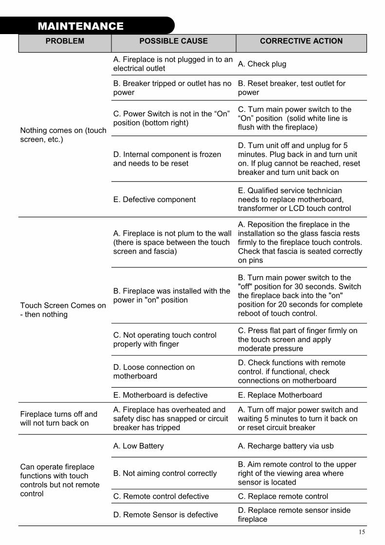
PROBLEM POSSIBLE CAUSE CORRECTIVE ACTION
Nothing comes on (touch screen, etc.)
A. Fireplace is not plugged in to an electrical outlet
A. Check plug
B. Breaker tripped or outlet has no power
B. Reset breaker, test outlet for power
C. Power Switch is not in the “On” position (bottom right)
C. Turn main power switch to the “On” position (solid white line is flush with the fireplace)
D. Internal component is frozen and needs to be reset
D. Turn unit off and unplug for 5 minutes. Plug back in and turn unit on. If plug cannot be reached, reset breaker and turn unit back on
E. Defective component E. Qualified service technician needs to replace motherboard, transformer or LCD touch control
Touch Screen Comes on - then nothing
A. Fireplace is not plum to the wall (there is space between the touch screen and fascia)
A. Reposition the fireplace in the installation so the glass fascia rests firmly to the fireplace touch controls. Check that fascia is seated correctly on pins
B. Fireplace was installed with the power in "on" position
B. Turn main power switch to the "off" position for 30 seconds. Switch the fireplace back into the "on" position for 20 seconds for complete reboot of touch control.
C. Not operating touch control properly with finger
C. Press flat part of finger firmly on the touch screen and apply moderate pressure
D. Loose connection on motherboard
D. Check functions with remote control. if functional, check connections on motherboard
E. Motherboard is defective E. Replace Motherboard
Fireplace turns off and will not turn back on
A. Fireplace has overheated and safety disc has snapped or circuit breaker has tripped
A. Turn off major power switch and waiting 5 minutes to turn it back on or reset circuit breaker
A. Low Battery A. Recharge battery via usb
Can operate fireplace functions with touch controls but not remote control
B. Not aiming control correctly B. Aim remote control to the upper right of the viewing area where sensor is located
C. Remote control defective C. Replace remote control
D. Remote Sensor is defective D. Replace remote sensor inside fireplace

16
CLEANING AND MAINTENANCE INSTRUCTIONS
There is very little maintenance involved with your electric fireplace. Please follow the few points be-low: On a semi-annual basis unplug the machine from it’s power source, wait for the heating element
to cool and dust the fire unit with a dry cloth. Be careful not to brush any wires that may be ex-posed as you do this.
To clean the glass face of the fireplace simply use your desired glass cleaner with paper towels. To clean the air inlets/outlets, wipe with a soft cloth or the nozzle of a vacuum cleaner Dust can easily build up around the heater area under the appliance. Take particular care to
clean this area on a regular basis to prevent buildup. If long time no use, please unplug the fireplace and stock it at indoor dry position.
WIRING DIAGRAM
MAINTENANCE MAINTENANCE
Touch Control
High
Heater
Low
HeaterPilot
Po
we
r
PC
B
FAN
MotorHeater
Sync
Motor
Relay PCB
Thermal
Cut-Off/
Fuse
AC L
AC N
1 2 3 COM
AC N
AC L 750W 750W Motor
Touch
12V1 IN1
ON/OFF
Heater
Control
Light
Control
J13
NTC
AC L
Motor FAN FAN
AC L AC L AC L AC L AC L
Heater
AC IN1
AC IN2
750W
750W FAN
FAN Motor
Motor
12V1 IN1 12V1 IN2
12V1 OUT112V1 OUT2
12V2 OUT112V2 OUT2
J13 IR
5V TX GND TR
12V -
Flame Light
Coal L
ight
Halo
Lig
ht
IR S
ensor
NT
C
Temperature
show
Temperature
Up
Temperature
Down

17
MAINTENANCE
NOTES

18
NOTES
MAINTENANCE MAINTENANCE

19
MAINTENANCE
NOTES

20
© 2015 www.modernflames.com
Please dispose of properly.


