www.sunelec.co.jp
2011-5
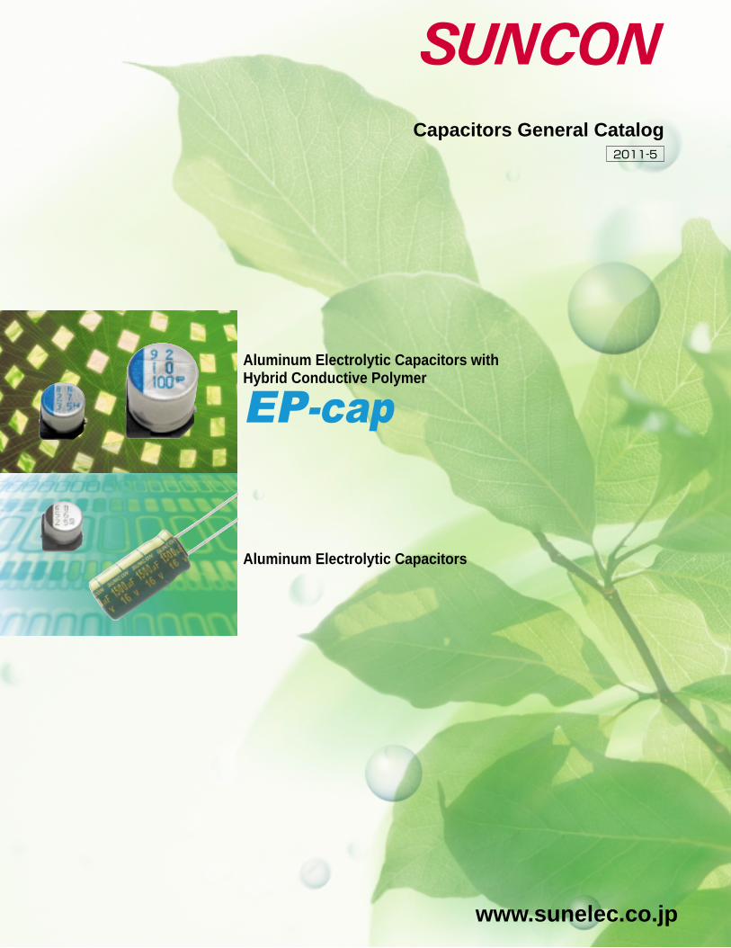
Capacitors General Catalog
Aluminum Electrolytic Capacitors with Hybrid Conductive Polymer
Aluminum Electrolytic Capacitors

■ The contents of this catalog are current as of May 2011. They may change without prior notice. When ordering products, please be sure to request a delivery specifications form and read it carefully.�
■ Products described herein are not intended for applications requiring extremely high reliability (for example, those in which extensive human injury or property damage may occur such as with life-support systems or aircraft control systems). For such applications, consult our sales department.�
■ The performance, characteristics, and features of the products described in this catalog are based on the products working alone under prescribed conditions. Data listed here is not intended as a guarantee of performance when working as part of any other product or device. In order to detect problems and situations that cannot be predicted beforehand by evaluation of supplied data, please always perform necessary performance evaluations with these devices as part of the product that they will be used in.�
■ When using the products listed in this catalog, please always be sure to try to prevent any possible accidents or injury by designing products in a careful and safe manner. If you have any questions concerning the use of these products, please contact any of our sales representatives.�
■ For any products listed in this catalog that may constitute restricted trade goods under overseas exchange or service trade laws, permission to deliver according to law may be required before importing.�
■ Unauthorized duplication of this catalog in part or in whole is forbidden. �
■ Please understand that we cannot be held responsible for any damages to the industrial properties of any third party that arise from the use or application of the products listed in this catalog, with the exception of those items directly related to method of construction.
Aluminum Electrolytic Capacitors
Aluminum ElectrolyticCapacitors with�Hybrid Conductive Polymer
Capacitors General Catalog
PRECAUTIONS
ISO Certificates�ISO/TS 16949� Izumo Plant ・ Head office� Certificate Number CERT-11075-2006-AQ-HOU-IATF (IATF 0080981)� Masuda Plant ・ Head office� Certificate Number CERT-11075CC1-2006-AQ-HOU-IATF (IATF 0080982)�
ISO 9001� Izumo Plant ・ Masuda Plant ・ Head office Certificate Number 01571-2001-AQ-KOB-JAB�
ISO 14001� Izumo Plant ・ Masuda Plant Certificate Number EMS 03 029
1
INDEX
‥‥‥ 17
About the electronic part capacitor�
Product Line-up Table ‥‥‥‥‥‥‥‥‥‥‥‥‥‥‥‥‥‥‥‥ 2�Series System Diagram ‥‥‥‥‥‥‥‥‥‥‥‥‥‥‥‥‥‥‥ 4�Guidelines and Precautions for Use ‥‥‥‥‥‥‥‥‥‥‥‥‥ 6�Environmental Consideration / �Surface Mount Type Recommended Land Pattern ‥‥‥‥‥ 10�Soldering Condition / Recommended Reflow Condition ‥‥‥‥ 11�Packing Specifications ‥‥‥‥‥‥‥‥‥‥‥‥‥‥‥‥‥‥ 12�Ripple Current Frequency Coefficient ‥‥‥‥‥‥‥‥‥‥‥ 15�Anti-vibration Structure ‥‥‥‥‥‥‥‥‥‥‥‥‥‥‥‥‥‥ 16
Aluminum Electrolytic Capacitors ‥‥‥‥‥‥‥‥‥‥‥‥‥ 27
Aluminum Electrolytic Capacitors with �Hybrid Conductive Polymer
CE-EXCE-GSCE-GXCE-FCCE-PXMV-AZ
MV(ME)-FAMV-EG,GX
MV-HWMV-HPS
MV-NPD,NPDW
HVACE-GACE-AXCE-FDCE-PCME-CZME-CZME-AXME-HC
ME-HPCME-HWN
Series integration
On new order, please order from Integrated series.
Discontinued�series
Integrated�series Feature
Hybrid Conductive Polymer, Super Low ESR�
Surface mount type, 5.4mm height, low impedance�
Surface mount type, low impedance, high-reliability�
Surface mount type, 4.5mm height�
Surface mount type, 125℃ Long life�
105℃ Standard�
105℃ Standard�
105℃ low impedance, high-reliability�
85℃ Standard �
85℃ Miniature, standard (mid.&high voltage)�
85℃ Bi-polar (miniature, standard)

UPGRADE
NEW
NEW
NEW
UPGRADE
UPGRADE
UPGRADE
2
Product Line-up Table About the electronic part capacitor
CE-BJ –––●� ●�
CE-BE –––●� ●�
CE-BD –––●� ●�
CE-BSS –––●� ●�
C E - C
–––●�CE-BS–––●� ●�
C E - F E
CE-FU
–––●� ●�
CE-FD –––●�
●�
●�
●� ●�
●� ●�
CE-LD –––
–––
●�●�
CE-FH –––●�
CE-GA –––●� ●�
CE-AX –––●� ●�
CE-KX –––●� ●�
CE-LS –––
–––
–––
●� ●�
CE-LX –––●� ●�
●� ●�
CE-PX
CE-PH
CE-PC
CE-LH
–––●�
●�
●�
●�●�
●�
●�
●�
●�
CE-NP
–––
–––
●�
●�●� ●�
CE-FN
–––
–––
★�
★�
★�
★�
●�
●�
●�CE-FS
CE-FSS
CE-LL
–––
●�
–––
H V H
H V A
H V B
–––
●� ●�
H V P–––
●�
●�
●�●�
●�●� ●�●�
●�●�●�
●�●�●�
●�●�●�
●�●�●�
23
22
24
28
29
30
31
32
34
35
36
37
38
39
40
42
43
44
46
50
53
51
52
48
54
56
57
58
Super Low Profile 3.25mm Height�
Super Low Profile 3.9mm Height�
Low Profile 4.5mm Height�
Miniature, Standard�
Standard�
φ3mm Version�
�
�
4.5mm Height, Long Life�
�
�
�
105℃, Standard�
�
Long Life�
�
Low Impedance�
Super Low Impedance�
Low Impedance, Long Life�
Low Impedance, Long Life�
Long Life�
Low Impedance, Long Life�
125℃, Long Life�
125℃�
�
Bi-polar
ー40 to +85�
ー40 to +85�
ー40 to +85�
ー40 to +85�
ー40 to +85�
ー40 to +85�
ー40 to +105�
ー40 to +105�
ー40 to +105�
ー40 to +105�
ー55 to +105�
ー40 to +105�
ー55 to +105�
ー40 to +105�
ー40 to +105�
ー55 to +105�
ー55 to +105�
ー55 to +105�
ー55 to +105�
ー40 to +105�
ー40 to +105�
ー40 to +105�
ー25 to +105�
ー55 to +125�
ー40 to +125�
ー40 to +125�
ー40 to +85�
ー55 to +105
4 to 50�
4 to 50�
4 to 50�
6.3 to 50�
4 to 100�
6.3 to 35�
6.3 to 50�
6.3 to 50�
6.3 to 50�
6.3 to 50�
6.3 to 50�
160 to 400�
6.3 to 63�
100�
6.3 to 50�
6.3 to 63�
6.3 to 50�
6.3 to 100�
6.3 to 100�
6.3 to 50�
6.3 to 50�
160 to 400�
6.3 to 50�
6.3 to 100�
6.3 to 50�
16 to 35�
6.3 to 50�
6.3 to 63
10 to 82�
1.0 to 180�
0.47 to 220�
4.7 to 220�
0.47 to 6800�
3.3 to 22�
1.0 to 100�
0.47 to 100�
0.47 to 100�
4.7 to 220�
2.2 to 100�
2.2 to 82�
0.47 to 10000�
1.0 to 220�
1.0 to 4700�
1.0 to 220�
4.7 to 6800�
3.3 to 6800�
4.7 to 10000�
10 to 330�
1.0 to 220�
2.2 to 82�
10 to 1000�
1.0 to 4700�
33 to 1500�
100 to 3300�
1.0 to 47�
1.0 to 47
Super Low ESR�
125℃�
Super Low ESR�
125℃�
135℃�
Super Low ESR�
Super Low ESR
Product Line-up Table of Aluminum Electrolytic Capacitors with Hybrid Conductive Polymer
Product Line-up Table of Surface Mount Type
Classification Series FeaturesCategory�Temperature�Range(℃)
External�Appearance
Marking�Color
Page Rated Voltage�
Range(V.DC)
Solvent�
Proof
Small & �
Thin type
Long�
Life
Low�
ESR
Rated�Capacitance�Range(μF)
Classification Series FeaturesCategory�Temperature�Range(℃)
External�Appearance
Marking�Color
Page Rated Voltage�
Range(V.DC)Solvent�
Proof
Small & �
Thin type
Long�
Life
Low�
Impedance
Rated�Capacitance�Range(μF)
Blue
––– Blue
––– Blue
Blue
BlueH V T
H E A
H E H
–––
25
26
Blue
––– Blue
Black
Black
Black
Black
Black
Black
Black
Black
Black
Black
––– Black
Black
Black
Black
Black
Black
Black
Black
Black
Black
Black
Black
Black
Black
Black
S.M.T
Surface Mount Type
3.9mm Height�Temperature of Wide Range
4.5mm Height�Temperature of Wide Range
5.4mm Height �Super Low Impedance
Bi-polar�Temperature of Wide Range
125℃ Low ESR,�High Capacitance
UPGRADEUPGRADE
ー55 to +105�
ー55 to +125�
ー55 to +105�
ー55 to +125�
ー55 to +135�
ー55 to +105�
ー55 to +105
6.3 to 16�
6.3 to 16�
25 to 125�
25 to 125�
25 to 63�
6.3 to 16�
25 to 100
10 to 1000�
22 to 560�
6.8 to 330�
6.8 to 330�
10 to 330�
10 to 1000�
10 to 330Radial�
Lead�
Type
High Temperature Reflow �Soldering
105℃ Miniature,�High Capacitance
47
50 1.0

UPGRADE
3
Product Line-up Table About the electronic part capacitor
Product Line-up Table of Radial Lead Type
WhiteME-UW ●� ●�
ME-SWB ●� ●�
ME-HC ●� ●�
●�ME-HPC
ME-HPD ●�
60
59
61
60
62
61
ME-UZ ●� ●�
ME-SZ ●� ●�
ME-CZ ●� ●�
●�M E - F C
ME-FD ●�
ME-FAZ ●�
ME-FH ●�
ME-UAX ●�●�
●�●�
●�●�
●�●�
●�
●�
●�
●�
●�
ME-CA
●�
ME-CX
●�
ME-AX
●�
●�
ME-WX
ME-WA
ME-WL–––
●�
MB-UWG
●�
●�
●�
●�
●� ●�
ME-SWG
★�
★�
★�
★�
●� ●�
ME-WG
●�
●�
●�
●�
●�
ME-FZ
★�
ME-PX
★�
ME-HLB
ME-HT
●� ●�
●� ●�
ME-SWN
ME-HWN
●�
●�●�
ME-SAX
●�
●�
ME-LS
63
64
66
68
70
72
74
76
77
80
80
78
79
81
81
82
83
84
85
ー40 to +85�
ー40 to +85�
ー55 to +105�
ー55 to +105�
ー55 to +105�
ー55 to +105�
ー40 to +105�
ー40 to +85�
ー55 to +105�
ー55 to +105�
ー55 to +105�
ー55 to +105�
ー40 to +105�
ー40 to +105�
ー40 to +105�
ー40 to +105�
ー40 to +105�
ー40 to +105�
ー40 to +105�
ー55 to +105�
ー55 to +125�
ー40 to +125�
ー25 to +125�
ー40 to +85�
ー25 to +85�
ー40 to +85�
ー25 to +85�
ー40 to +105�
ー25 to +105�
ー40 to +105�
ー25 to +105�
ー40 to +105�
ー40 to +105�
ー25 to +105�
ー40 to +85�
ー40 to +85�
ー40 to +85�
ー40 to +85
4 to 50�
4 to 63�
6.3 to 50�
6.3 to 50�
6.3 to 35�
6.3 to 35�
6.3 to 50�
6.3 to 100�
6.3 to 100�
6.3 to 50�
6.3 to 35�
6.3 to 63�
100�
6.3 to 50�
6.3 to 50�
6.3 to 63�
6.3 to 25�
6.3 to 35�
6.3 to 25�
10 to 50�
10 to 100�
160 to 250�
350 to 400�
160 to 250�
350 to 450�
160 to 250�
350 to 450�
160 to 400�
450�
160 to 400�
450�
160 to 250�
160 to 400�
450�
16 to 50�
10 to 50�
6.3 to 50�
6.3 to 100
10 to 330�
10 to 470�
10 to 220�
1.0 to 330�
33 to 220�
4.7 to 330�
1.0 to 1000�
1.0 to 15000�
2.2 to 15000�
2.2 to 15000�
47 to 15000�
4.7 to 12000�
5.6 to 470�
22 to 6800�
100 to 8200�
1.0 to 330�
39 to 150�
22 to 330�
220 to 3300�
10 to 4700�
1.0 to 4700�
10 to 150�
4.7 to 47�
0.47 to 220�
0.47 to 100�
47 to 220�
10 to 68�
0.47 to 220�
1.0 to 47�
22 to 220�
10 to 33�
1.0 to 220�
10 to 220�
6.8 to 68�
2.2 to 100�
1.0 to 2200�
1.0 to 47�
2.2 to 2200
5mm Height�
7mm Height�
�
�
�
�
Standard�
�
�
Miniature, Low Impedance�
�
Low Impedance・High Ripple�
�
�
5mm Height,Low ESR�
7mm Height,Low ESR�
Super Low ESR�
�
�
125℃,High Performance�
�
�
�
�
�
�
�
�
High Ripple(Mid.Voltage)�
�
Low Leakage Current�
Timer Circuit Use�
7mm Height,Bi-polar�
Miniature, Standard,Bi-polar
Classification Series FeaturesCategory�Temperature�Range(℃)
External�Appearance
Marking�Color
Page Rated Voltage�
Range(V.DC)
Solvent�
Proof
Small & �
Thin type
Long�
Life
Rated�Capacitance�Range(μF)
Black
Black
Black
Black
Black
Black
Black
Black
Black
Black
Green
Green
Green
Green
Green
Green
Green
Green
Green
Green
Green
Green
Black
Black
Black
Black
Black
Black
Black
Black
Black
Blue
Gold
Gold
Gold
Gold
Gold
Gold
Gold
Gold
Silver
Silver
Silver
Silver
Clear�Green
White
White
White
White
White
White
White
White
White
White
White
White
White
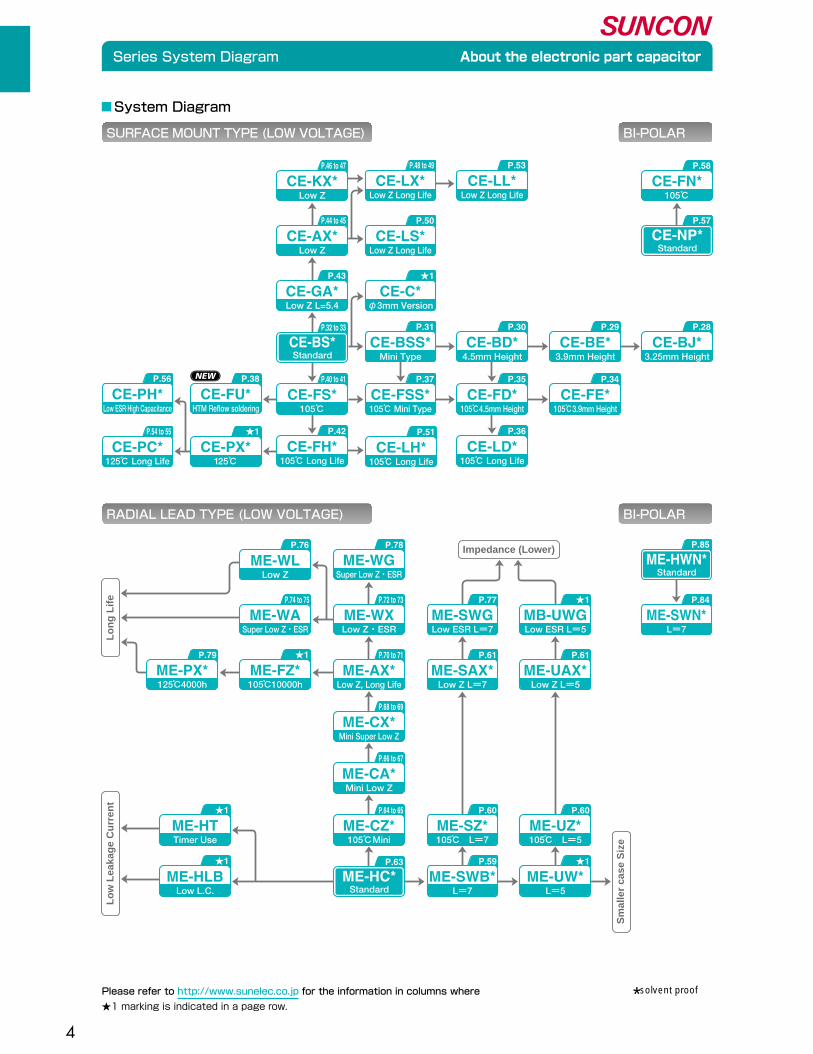
★�Please refer to http://www.sunelec.co.jp for the information in columns where marking is indicated in a page row.
Miniature, Standard�(Mid. & High Voltage)
Miniature, Low Profile�(Mid. & High Voltage)
5mm Height, �Temperature of Wide Range7mm Height, �Temperature of Wide Range
Miniature, Standard�Temperature of Wide Range
5mm Height,�Low Impedance7mm Height,�Low ImpedanceLong Life,�High-Reliability
Miniature, Standard�Low Impedance
Low Impedance,�Long Life
Low Impedance・High Ripple�Long LifeLow Impedance�Long Life
Extra Long Life,�High Performance
Miniature, Guaranteed 105℃�(Mid. & High Voltage)
105℃, Miniature, Low Profile�(Mid. & High Voltage)
105°C, Long Life�(Mid. & High Voltage)
Radial Lead Type
Low�
Impedance
2.22.2
22
2.2
22
2.2
222.2
22
2.2
2.2
22
2.2
6.8
22
4
Series System Diagram About the electronic part capacitor
Please refer to http://www.sunelec.co.jp for the information in columns where
★1 marking is indicated in a page row.
System Diagram
*solvent proof
RADIAL LEAD TYPE (LOW VOLTAGE) BI-POLAR
SURFACE MOUNT TYPE (LOW VOLTAGE) BI-POLAR
Super Low Z・ESRME-WG
Low Z・ESRME-WX
Low Z, Long LifeME-AX*
L=7ME-SWN*
Mini Super Low ZME-CX*
Mini Low ZME-CA*
105℃MiniME-CZ*
Super Low Z・ESRME-WA
★1
105℃10000hME-FZ*
125℃4000hME-PX*
StandardME-HC*
StandardME-HWN*
Low ESR L=7ME-SWG
Low Z L=7ME-SAX*
105℃ L=7ME-SZ*
L=7ME-SWB*
★1
Timer UseME-HT
★1
Low L.C.ME-HLB
Low ESR L=5MB-UWG
Low Z L=5ME-UAX*
105℃ L=5ME-UZ*
L=5ME-UW*
P.78
P.72 to 73
P.70 to 71
P.68 to 69
P.66 to 67
P.64 to 65
P.74 to 75
P.79
P.63
P.77
P.61
P.60
P.59
★1
P.61
P.85
P.84
P.60
★1
P.53
Low Z Long LifeCE-LL*
P.46 to 47
Low ZCE-KX*
P.44 to 45
Low ZCE-AX*
P.58
105℃�CE-FN*
P.43
Low Z L=5.4CE-GA*
P.40 to 41
105℃�CE-FS*
P.42
105℃ Long LifeCE-FH*
P.35
105℃4.5mm HeightCE-FD*
P.36
105℃ Long LifeCE-LD*
P.32 to 33
StandardCE-BS*
P.57
StandardCE-NP*
★1
φ3mm VersionCE-C*
P.50
Low Z Long LifeCE-LS*
P.48 to 49
Low Z Long LifeCE-LX*
P.51
105℃ Long LifeCE-LH*
P.37
105℃ Mini TypeCE-FSS*
P.31
Mini TypeCE-BSS*
★1
125℃�CE-PX*
P.30
4.5mm HeightCE-BD*
P.34
105℃3.9mm HeightCE-FE*
P.29
3.9mm HeightCE-BE*
P.28
3.25mm HeightCE-BJ*
P.56
Low ESR·High CapacitanceCE-PH*
P.38
HTM Reflow solderingCE-FU*
P.54 to 55
125℃ Long LifeCE-PC*
P.76
Low ZME-WL
Impedance (Lower)
Lo
w L
eaka
ge
Cu
rren
t
Sm
alle
r ca
se S
ize
Lo
ng
Lif
e
5
Series System Diagram About the electronic part capacitor
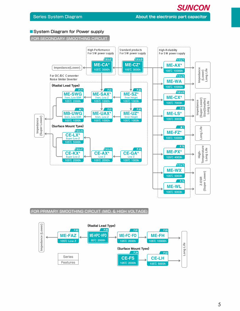
System Diagram for Power supply
High-PerformanceFor SW power supply
For DC/DC ConverterNoise limiter Inverter
High-ReliabilityFor SW power supply
(Radial Lead Type)
(Radial Lead Type)
(Surface Mount Tyee)
(Surface Mount Tyee)
FOR SECONDARY SMOOTHING CIRCUIT
FOR PRIMARY SMOOTHING CIRCUIT (MID. & HIGH VOLTAGE)
Impedance(Lower)
P.46 to 47
105℃ 2000hSuper Low ZCE-KX*
P.44 to 45
105℃ 2000hLow ZCE-AX*
P.48 to 49
105℃ 5000hSuper Low ZCE-LX*
P.43
105℃ 1000hLow Z
CE-GA*
★1
105℃ 1000h5mm, Low ESRMB-UWG
P.61
105℃ 1000h5mm, Low ZME-UAX*
P.60
105℃ 1000h5mm HeightME-UZ*
P.77
105℃ 2000h7mm, Low ESRME-SWG
P.61
105℃ 1000h7mm, Low ZME-SAX*
P.60
105℃ 1000h7mm HeightME-SZ*
P.66 to 67
105℃ 3000h
ME-CA*
Standard productsFor SW power supply
P.64 to 65
105℃ 3000h
ME-CZ*P.70 to 71
105℃ 10000h
ME-AX*
P.74 to 75
105℃ 10000h
ME-WA
P.72 to 73
105℃ 5000h
ME-WX
P.76
105℃ 5000h
ME-WL
P.68 to 69
105℃ 7000h
ME-CX*
P.62
105℃ 3000h
ME-LS*
★1
105℃ 10000h
ME-FZ*
P.79
125℃ 4000h
ME-PX*
Imp
edan
ce(S
up
er L
ow
er)
Imp
edan
ce(L
ow
er)
Lo
ng
Lif
e
Imp
edan
ce(S
up
er L
ow
er)
Siz
e(S
mal
ler)
Lo
ng
Lif
e
Lo
ng
Lif
eH
igh
-Te
mp
erat
ure
Lo
ng
Lif
e
Z-E
SR
(Su
per
Lo
wer
)
P.83
105℃ 10000h
ME-FHP.82
105℃ Low Z
ME-FAZP.81
105℃ 2000h
ME-FC・FD
P.39
105℃ 2000h
CE-FS
P.80
85℃ 2000h
ME-HPC・HPD
P.52
105℃ 5000h
CE-LH
Imp
edan
ce (
Lo
wer
)
Lo
ng
Lif
e
Features
Series

6
Guidelines and Precautions for Use About the electronic part capacitor
Please observe the following guidelines when using aluminum electrolytic capacitors. (Hereafter "Capacitors")
1)�
�
�
2)�
�
�
�
�
�
�
�
�
3)�
�
4)�
�
�
�
�
5)�
�
�
6)�
�
7)�
�
�
�
8)�
�
�
�
�
�
9)�
�
�
�
�
�
�
10)�
Circuit Diagram
Please use according to the values noted in the catalogue or the specification sheet when considering the application
and use of the capacitors.�
�
Please use according to the temperature range and rated ripple current as noted in the catalogue or the specification
sheet.�
a)Life time of electrolytic capacitors depends on the ambient temperature.�
Generally the life time would be doubled as the temperature decreased by 10 degrees.�
It is recommended that capacitors be used at a lower temperature than that of the maximum warranty as possible.�
b)Capacitors should be used at current values within the rated ripple current.�
If capacitor bears excessive ripple current, heat generation acutely increases, therefore decreasing capacitance or
even damage the capacitor. Please refer to the rated ripple current of each series.�
�
Please choose the capacitor that matches the lifetime of the intended circuit design.�
�
Regular capacitors have polarity. If electrical current is applied in the opposite direction to a capacitors polarity, the
result could be a short circuit or destruction of the capacitor.�
Bi-polar capacitors should be used in circuit where polarity is occasionally reversed, or where polarity is unknown.
(except AC)�
�
In circuits where frequent charge and discharge are common, capacitance decrease as the internal overheat causes
damage to capacitors. In such circuits, please use charge and discharge proof capacitors.�
�
Do not apply DC-voltage exceeding rated voltage of the capacitors.�
�
The exterior sleeve of a capacitor is not guaranteed as an insulator.�
Do not use the capacitor where insulation is required.�
The aluminum case of a capacitor is not insulated from a cathode lead wire.�
�
Do not use in the following environments.�
a)In the environments of splashed water, salt water, and oil on the capacitors.�
b)In the presence of poisonous gas. (Hydrogen sulfide, Sulfurous acid, Chlorine, Ammonia, etc)�
c)In the environments of applied ozone, ultraviolet rays and radial rays.�
d)Where vibration or shock exceeds the allowable values as noted in the catalogue or specification sheet.�
�
Please design after confirming the following points concerning the application and use.�
a)Please match the leads space with the holes space of the circuit board.�
b)It is recommended at least 3mm of space around the pressure relief vent.�
c)Avoid placing to printed wire above the pressure relief vent.�
d)Make a hole on a circuit board if the top of an aluminum case is positioned below the circuit board at short distance.
The hole is to make the passage of gas from a safety vent when the vent opens.�
�
Avoid having the printed wire under the capacitor.
7
Guidelines and Precautions for Use About the electronic part capacitor
1)�
�
�
�
2)�
�
3)�
�
�
4)�
�
5)�
�
6)�
�
7)�
�
8)�
�
9)�
�
�
10)�
�
�
11)�
�
12)�
Mounting
Do not use a capacitor that has been inserted and connected to a current.�
Except for capacitors that have been removed to check the electrical properties during periodical checks, do not
reuse.�
�
In case the capacitor has re-striking-voltage, please discharge through 1kΩ resistor.�
�
In case the leakage current increases with long term storage, please apply the rated voltage to the capacitor for 30
minutes through 1kΩ of protective series resistors.�
�
Please mount capacitor after confirmation of following rates : rated capacitance, rated voltage.�
�
Please mount after confirming the polarity of capacitor.�
�
Do not drop or use dropped pieces.�
�
Be careful not to deform the capacitor during installation.�
�
Be careful not to puncture the aluminum case of a capacitor with excessive impact.�
�
When mounting capacitors to the circuit board, please use capacitors that the lead space equal the hole space of the
circuit board.�
�
When mounting capacitors with automatic inserting machines, do not apply excessive force to the lead wire or
terminals.�
�
When mounting capacitors with automatic inserting machines, do not apply excessive force to the body of capacitors.�
�
Please confirm the following points when you solder with a soldering iron.�
a)Follow the criteria of soldering condtion including time and temperature noted in a catalogue or a specification.�
b)Process the shape of lead wires before soldering when the lead wire space of a capacitor does not match the
through hole space of a circuit board,Avoid the stress to the body of the capacitor.�
c)Melt solder enoght to rework a capacitor with a soldering iron after removing it from a circuit board.�
Insufficence of melting solder causes physical stree to lead wires.�
d)Do not touch the body of a capacitor with the tip of a soldering iron.
11)�
�
12)�
�
�
13)�
Avoid placing other parts near or on the opposite side of the circuit board from the capacitor which gives off heat.�
�
As for the land pattern of surface mount type capacitors, please refer to the values noted in the catalogue or
specification sheet.�
�
Please design after confirming these other following points.�
a)The performance of the capacitor will vary as the temperature or frequency varies.�
b)If capacitor is mounted to the double sided circuit board, avoid placing through holes under capacitors.�
c)Please consider the balance of the current when using two or more capacitors in parallel.�
d)Please consider the balance of the voltage when using two or more capacitors in series.

8
Guidelines and Precautions for Use About the electronic part capacitor
13)�
�
�
�
�
�
�
�
14)�
�
�
�
�
�
15)�
�
�
�
�
�
�
16)�
�
�
�
�
�
�
�
�
�
�
17)�
�
�
�
�
18)�
�
19)�
Please confirm the following points when you performe flow soldering.�
a)Do not soak a capacitor in melt solder. Perform flow soldering only on the opposite side of a circuit board where no
capacitor is placed.�
b)Follow the instruction in a catalogue or a specification with regard to the soldering condition; preheat, soldering
temperature, and soaking time.�
c)Avoid the attachment of flux to the body of a capacitor except lead wires.�
d)Do not locate a capacitor where metal lead wires of the other components conatct with the capacitor.�
�
Please confirm the following points when you performe reflow soldering.�
a)Follow the specifications for pre-heat, reflow time and peak temperature as noted in the catalogue or specification
sheet.�
b)The absorption coefficient of infrared rays depends on the color and material of a capacitor.�
Avoid heating too much to a capacitor by an infrared heater.�
�
After mounting the circuit board, do not apply the following mechanical stress.�
a)Do not apply excessive force to the lead wires or terminals.�
b)Do not tilt or bring down the capacitor.�
c)Do not pick up circuit board by holding the mounted capacitor.�
d)Do not jolt the capacitor. When stacking circuit boards, make sure the capacitor does not come into contact with
any other parts.�
�
In principle,aluminum electrolytic capacitors are not designed to withstand to the cleaning solvent.�
If cleaning of a board is necessary,select capacitor designed to withstand cleaning process, and observe the cleaning
conditions specified in the catalogue or in the manufactures specification.�
Do not clean the capacitors using solvent, unless so specified in catalogue or manufactures spscification.�
Use of one of the following chemicals for cleaning may damage the capacitor.�
a)Solvent containing halogen ions : Damage due to electrolysis of elements�
b)Alkaline solvent : Corrosion of the aluminum case�
c)Xylene : Degradation of sealing rubber�
d)Acetone : Disappear of markings.�
e)Terpene,petro-based solvents : Degradation of sealing rubber�
�
When cleaning solvent proof capacitors, please confirm the following points.�
a)Please manage the pollution of the cleaning solvent. (conductivity, pH, specific gravity, content of water, etc)�
b)Do not keep in the environments of cleaning solvents or airtight containers, after cleaning the capacitors.�
Please dry the circuit board and capacitors in a hot blast stove within upper category temperature or less.�
�
When using polymer adhesives, select adhesives without halogenated solvents, nor chloroprene.�
�
Please confirm the following when using coating agents and polymer adhesives.�
a)When adhesion or coating is performed after cleaning, air dry should be made immediately remove cleaning solvent
between capacitors and circuit board.�
b)Avoid the treatment that cover the seal of the capacitor, such as coating agents and use of polymer adhesive.
1)�
�
2)�
During operation or use
Do not directly touch the capacitor.�
�
Do not short two lead wires with any conductive material.�
Do not spray acid or alkali conductive solution to a capacitor.

9
Guidelines and Precautions for Use About the electronic part capacitor
1)�
�
2)�
Maintenance ・ Inspection
For industrial use, please periodically check the capacitor.�
�
When checking, inspect the following points.�
a)Outside appearance.�
b)Electrical performance. (Leakage current, Capacitance, Tangent of loss angle, etc)
3)�Confirm the following concerning the operating environments.�
a)In the environments of splashed water, salt water, and oil on the capacitors.�
b)Where a capacitor is exposed to direct sunshine.�
c)In the environments of applied ozone, ultraviolet rays and radial rays. �
d)Where vibration or shock exceeds the allowable values as noted in the catalogue or specification sheet.
1)�
�
�
2)�
�
�
3)�
In case a problem occurs
While using the application, if you see gas, turn off the main power supply to the set or remove the plug from the
outlet.�
�
When working with a pressure relief vent, high temperature gas spouts out, therefore, do not bring the face close to
the capacitor.�
�
In case spouted gas got into the eye, immediately wash with the water.�
In case you breath spouted gas, immediately rinse out your mouth.
1)�
�
�
2)�
�
3)�
�
4)�
Storage conditions
Do not store at high temperatures or in high humidity. Please store indoors between 5℃ and 35℃ at 75% relative
humidity or below.Product is safekeeping for less than 1 year after shipment.�
�
Do not store where it can come into contact with water, oil, or salt water.�
�
Do not store in an environment with poisonous gas. (Hydrogen sulfide, Sulfurous acid, Chlorine, Ammonia, etc)�
�
Do not store in an environment that applys ozone, ultraviolet rays, radial rays.
Scrap of capacitors
Please follow these guidelines when scrapping the capacitors.�
a)Burn after putting a hole in the capacitor or crush the capacitor.�
b)If you do not burn it, please arrange for a professional waste management firm to bury or use other method to scrap.
This guide to use aluminum electrolytic capacitors conform to technical report EIAJ RCR-2367B "Guideline of notabilia
for fixed aluminum electrolytic capacitors for use in electronic equipment".�
Please refer to this technical report for additional details.

10
Environmental Consideration / Surface Mount Type Recommended Land Pattern About the electronic part capacitor
●Land pattern
The environmental products are available with Pb-free products which don't include Pb in terminals of main
body and PVC-free products which don't include exterior materials. Please contact us about the
specification etc.
■ Environmental Products (Compliance of RoHS Directive)
Type code
Kind of plating
CE, HV★1 CE_T ME MB, HE_T
(φ3 to φ12.5)� (φ16, φ18)�
Model No.�(example)
10CE100BS�(100μF/10V)�
10CE4700BST�(4700μF/10V)�
10ME100AX�(100μF/10V)�
10MB100UWG�(100μF/10V)�
Surface Mount Type�Aluminum Electrolytic Capacitors
Radial Lead Type�Aluminum Electrolytic Capacitors
Fe
Cu
Sn-Bi
Fe
Cu
Sn
Fe
Cu
Sn
Fe
Cu
Sn
Sleeve No used No used PET No used
Moisture Sensitivity�Level (MSL)★2
Not applicable�No need dry package
Not applicable�No need dry package
Not applicable�No need dry package
Not applicable�No need dry package
(★2 Conform to IPC/JEDEC J-STD-020C)★1 Sn plating terminal of Surface Mount Type : "CE_T", "HV_T"
c�
b�b� a�
We promote the activities which are considered for ecology.
According to the content of RIP3.8TGD (Technical Guidance Document) which is published on 26 May
2008, our electronic components are "articles without any intended releas". Therefore they are not
applicable for "Registration" for European REACH Regulation Article 7 (1).
Regarding compliance to European REACH Regulation.
Surface Mount Type Recommended Land Pattern
(Unit:mm)�
Size a b c
φ3�
φ4�
φ5�
φ6.3�
φ8�
φ10�
φ12.5�
φ16�
φ18
0.8�
1.0�
1.4�
1.8�
2.8�
4.3�
4.3�
6.6�
6.6
2.2�
2.6�
3.0�
3.6�
4.1�
4.4�
5.8�
6.5�
7.7
1.7�
1.8�
1.8�
1.8�
2.1�
2.5�
2.5�
5.0�
5.0
When using large surface mount capacitor, please design possibly larger land pattern area than the recommended pattern �dimension in order to increase vibration resistance and avoid to falling off a circuit board.
11
Soldering Condition / Recommended Reflow Condition About the electronic part capacitor
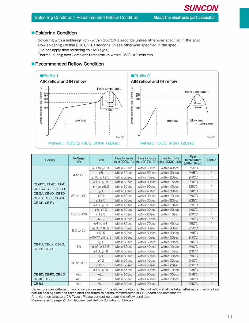
・ Soldering with a soldering iron - within 350℃×3 seconds unless otherwise specified in the spec.�・ Flow soldering - within 260℃×10 seconds unless otherwise specified in the spec.� (Do not apply flow soldering to SMD type.)�・ Thermal curing over - ambient temperature within 150℃×2 minutes.
●Profile 1
AIR reflow and IR reflow
Preheat ; 150℃ to 180℃, Within 120sec.
●Profile 2
AIR reflow and IR reflow
Preheat ; 150℃, Within 120sec.
Sur
face
of e
xter
nal c
ase
/ ter
min
al [℃
]
Sur
face
of e
xter
nal c
ase
/ ter
min
al [℃
]
preheat
Peak temperature
Time [S] Time [S]
Soldering Condition
Recommended Reflow Condition
Capacitors can withstand two reflow processes on the above conditions. Second reflow shall be taken after more than one hour �natural cooling time and taken after the return to normal temperatures of PCB board and components.�Anti-vibration structure(CA Type) ; Please contact us about the reflow condition.�Please refer to page 21 for Recomended Reflow Condition of EP-cap.
CE-BSS, CE-BS, CE-C�
CE-FSS, CE-FS, CE-FH�
CE-GA, CE-AX, CE-KX�
CE-LH, CE-LL, CE-PX�
CE-NP, CE-FN
CE-BD, CE-FD, CE-LD�
CE-BE, CE-FE�
CE-BJ
CE-FU, CE-LX, CE-LS, �
CE-PC, CE-PH
�
4 to 63�
�
�
�
80 to 100�
�
�
�
160 to 400�
�
�
6.3 to 50�
�
�
63�
�
�
80 to 100�
�
ALL�
ALL�
ALL
φ3 to φ6.3�
φ8�
φ10, φ12.5�
φ16, φ18�
φ4 to φ6.3�
φ8�
φ10�
φ12.5�
φ16, φ18�
φ8, φ10�
φ12.5�
φ16�
φ4 to φ8�
φ10×10.2, 13.5�
φ12.5�
φ10×7.7, φ16, φ18�
φ8�
φ10, φ12.5�
φ16, φ18�
φ8�
φ10�
φ12.5�
φ16, φ18�
ALL�
ALL�
ALL
Within 70sec.�
Within 60sec.�
Within 50sec.�
Within 50sec.�
Within 60sec.�
Within 60sec.�
Within 50sec.�
Within 50sec.�
Within 45sec.�
Within 50sec.�
Within 45sec.�
Within 30sec.�
Within 80sec.�
Within 70sec.�
Within 60sec.�
Within 50sec.�
Within 60sec.�
Within 50sec.�
Within 50sec.�
Within 60sec.�
Within 50sec.�
Within 50sec.�
Within 45sec.�
Within 60sec.�
Within 50sec.�
Within 30sec.
Within 40sec.�
Within 30sec.�
Within 20sec.�
Within 15sec.�
Within 40sec.�
Within 30sec.�
Within 20sec.�
Within 20sec.�
Within 10sec.�
Within 20sec.�
Within 10sec.�
―�
Within 40sec.�
Within 40sec.�
Within 30sec.�
Within 20sec.�
Within 30sec.�
Within 20sec.�
Within 15sec.�
Within 30sec.�
Within 20sec.�
Within 20sec.�
Within 10sec.�
Within 30sec.�
Within 20sec.�
―�
250℃�
245℃�
240℃�
235℃�
250℃�
240℃�
240℃�
235℃�
235℃�
240℃�
235℃�
230℃�
260℃�
250℃�
245℃�
240℃�
245℃�
240℃�
235℃�
240℃�
240℃�
235℃�
235℃�
245℃�
240℃�
230℃�
1�
1�
1�
1�
1�
1�
1�
1�
1�
1�
1�
2�
1�
1�
1�
1�
1�
1�
1�
1�
1�
1�
1�
1�
1�
2
Time for more�than 200℃ (t)
Time for more�than 230℃ (t2)
Peak�temperature�(Within 5sec.)
ProfileSizeVoltage�(V)Series
Within 60sec.�
Within 50sec.�
Within 40sec.�
Within 30sec.�
Within 50sec.�
Within 40sec.�
Within 30sec.�
Within 30sec.�
Within 20sec.�
Within 30sec.�
Within 20sec.�
Within 15sec.�
Within 70sec.�
Within 60sec.�
Within 50sec.�
Within 40sec.�
Within 50sec.�
Within 40sec.�
Within 40sec.�
Within 50sec.�
Within 40sec.�
Within 40sec.�
Within 30sec.�
Within 50sec.�
Within 40sec.�
Within 20sec.
Time for more�than 217℃ (t1)
230
200217
150
0
180
T
t max
230
200217
150
0
t max
t1 max
reflow time (30sec.max)
preheat
Peak temperature
t1 max
t2 max
φ10×10.2
12
Packing Specifications About the electronic part capacitor
Carrier tape φD≤10 φD≥12.5
(Unit:mm)Surface Mount Type Taping Specifications
+�
-�
+�
-�
+�
-�
+�
-�
+�
-�
4.0±0.1 2.0±0.1 φ1.5+0.1-0
P H
FE
Y
Leading
+�
-�
+�
-�
+�
-�
Leading
H R0.75 0.2
4.0±0.12.0±0.1
0.6max
φ1.5+0.1-0
P
FE
YS
T
W
(Unit:mm)
(Unit:mm)
2
13±0.5
21min.
380±2(330±2)
G 3
50min.
Reel
Minimum Packing Quantity
When you place an order, please make sure that order should be integral multiple of the minimum packing unit.
★1 Reel code has to be specified after the model number.�Model No. 25CE47BS+E
Reel code
★2 Reel code has to be specified after the model number.�Model No. 25CE2200LXT+D
Reel code
φ3、φ4、φ5�
φ6.3�
φ8、φ10�
φ12.5�
φ16、φ18
14�
18�
26�
34�
46
G
★ Anti-vibration Structure : CA Type
Y±0.3φ3×5.4�φ4×4.5�φ4×5.4�φ4×6.0�φ5×3.9�φ5×4.5�φ5×5.4�φ5×6.0�φ5×7.0�φ6.3×3.25�φ6.3×3.9�φ6.3×4.5�φ6.3×5.4�φ6.3×6.0�φ6.3×7.0�φ6.3×7.7�φ6.3×8.4�φ8×10.2(10.5)�φ10×7.7�φ10×10.2(10.5)�φ10×12.5�φ10×13.5�φ12.5×13.5�φ16×16.5�φ18×16.5
12.0�12.0�12.0�12.0�12.0�12.0�12.0�12.0�12.0�16.0�16.0�16.0�16.0�16.0�16.0�16.0�16.0�24.0�24.0�24.0�24.0�24.0�32.0�44.0�44.0
H±0.23.7�4.7�4.7�4.7�5.7�5.7�5.7�5.7�5.7�7.0�7.0�7.0�7.0�7.0�7.0�7.0�7.0�8.7�10.7�10.7�10.7�10.7�13.2�17.5�19.5
(13.9★)� (13.9★)�
W±0.23.7�4.7�4.7�4.7�5.7�5.7�5.7�5.7�5.7�7.0�7.0�7.0�7.0�7.0�7.0�7.0�7.0�8.7�10.7�10.7�10.7�10.7�13.2�17.5�19.5
P±0.18.0�8.0�8.0�8.0�12.0�12.0�12.0�12.0�12.0�12.0�12.0�12.0�12.0�12.0�12.0�12.0�12.0�16.0�16.0�16.0�16.0�16.0�24.0�28.0�32.0
E±0.11.75�1.75�1.75�1.75�1.75�1.75�1.75�1.75�1.75�1.75�1.75�1.75�1.75�1.75�1.75�1.75�1.75�1.75�1.75�1.75�1.75�1.75�1.75�1.75�1.75
F±0.15.5�5.5�5.5�5.5�5.5�5.5�5.5�5.5�5.5�7.5�7.5�7.5�7.5�7.5�7.5�7.5�7.5�11.5�11.5�11.5�11.5�11.5�14.2�20.2�20.2
T±0.25.8�5.0�5.8�6.4�4.5�5.0�5.8�6.4�7.1�3.8�4.5�5.1�5.8�6.5�7.5�8.2�9.2�
11.1�8.3�11.2�13.3�14.5�14.3�17.3�17.8
S±0.1ー�ー�ー�ー�ー�ー�ー�ー�ー�ー�ー�ー�ー�ー�ー�ー�ー�ー�ー�ー�ー�ー�28.4�40.4�40.4
(14.7★)�(17.8★)�
size(φD×L)�
2000�2000�2000�2000�ー�ー�ー�
1000�1000�ー�ー�ー�
1000�1000�900�800�500�500�500�400�400�250�200�175
1500�1500�1500�1200�1000�1000�1000�800�800�1000�1000�1000� 800�800� 500�500� 300� 400�300� 300�ー�ー�ー�ー�
5�5�5�5�5�5�5�5�5�5�5�5�5�5�5�5�3�3�3�3�3�2�2�2
★1�★1�★1�★1����★1�★1����★1�★1�★1�★1�★1�★1�★1�★1
���������������������★2�★2���
φ3×5.4�φ4×4.5�φ4×5.4�φ4×6.0�φ5×3.9�φ5×4.5�φ5×5.4�φ5×6.0�φ5×7.0�φ6.3×3.25,3.9�φ6.3×4.5�φ6.3×5.4�φ6.3×6.0�φ6.3×7.0�φ6.3×7.7�φ6.3×8.4�φ8×10.2(10.5)�φ10×7.7�φ10×10.2(10.5)�φ10×12.5�φ10×13.5�φ12.5×13.5�φ16×16.5�φ18×16.5
φD×L(mm)� Quantity of 1 Reel(φ380) Quantity of 1 Reel(φ330) Quantity of 1 package(Reel)
13
Packing Specifications About the electronic part capacitor
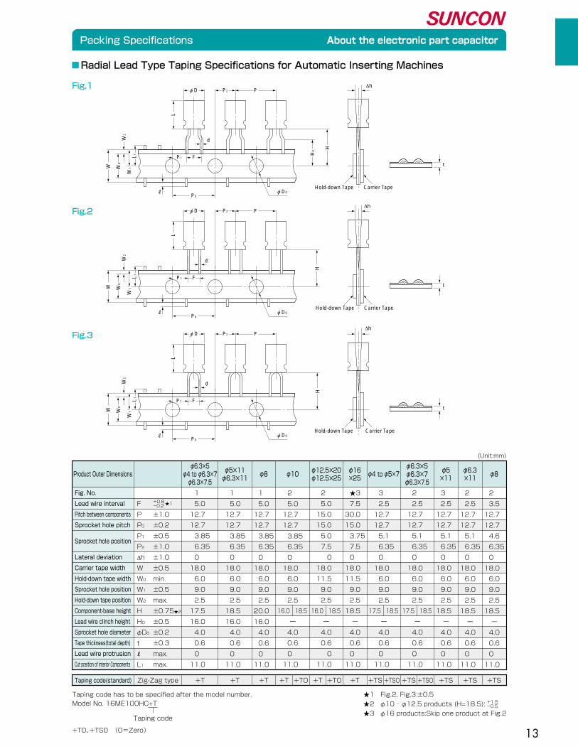
Radial Lead Type Taping Specifications for Automatic Inserting Machines
(Unit:mm)
Fig.1
Fig.2
Fig.3
Hold-down Tape Carrier Tape
t
φD0P0
P1L1W
1
W2
W0
W
H0
H
d
F
P2φD P
L
Hold-down Tape Carrier Tape
t
φD0P0
P1L1W
1
W2
W0
W
H
d
F
P2φD P
L
Hold-down Tape Carrier Tape
t
φD0P0
L1W
1
W2
W0
W
P2
H
φD P
L
P1 F
d
Product Outer Dimensionsφ6.3×5�
φ4 to φ6.3×7�φ6.3×7.5
φ5×11�φ6.3×11
φ12.5×20�φ12.5×25
φ8 φ10 φ16�×25
φ4 to φ5×7φ6.3×5�φ6.3×7�φ6.3×7.5
φ5�×11
φ6.3�×11
φ8
1�
5.0�
12.7�
12.7�
3.85�
6.35�
0�
18.0�
6.0�
9.0�
2.5�
17.5�
16.0�
4.0�
0.6�
0�
11.0
1�
5.0�
12.7�
12.7�
3.85�
6.35�
0�
18.0�
6.0�
9.0�
2.5�
18.5�
16.0�
4.0�
0.6�
0�
11.0
1�
5.0�
12.7�
12.7�
3.85�
6.35�
0�
18.0�
6.0�
9.0�
2.5�
20.0�
16.0�
4.0�
0.6�
0�
11.0
2�
5.0�
12.7�
12.7�
3.85�
6.35�
0�
18.0�
6.0�
9.0�
2.5�
16.0 18.5�
ー�
4.0�
0.6�
0�
11.0
2�
5.0�
15.0�
15.0�
5.0�
7.5�
0�
18.0�
11.5�
9.0�
2.5�
16.0 18.5�
ー�
4.0�
0.6�
0�
11.0
★3�
7.5�
30.0�
15.0�
3.75�
7.5�
0�
18.0�
11.5�
9.0�
2.5�
18.5�
ー�
4.0�
0.6�
0�
11.0
3�
2.5�
12.7�
12.7�
5.1�
6.35�
0�
18.0�
6.0�
9.0�
2.5�
17.5 18.5�
ー�
4.0�
0.6�
0�
11.0
2�
2.5�
12.7�
12.7�
5.1�
6.35�
0�
18.0�
6.0�
9.0�
2.5�
17.5 18.5�
ー�
4.0�
0.6�
0�
11.0
3�
2.5�
12.7�
12.7�
5.1�
6.35�
0�
18.0�
6.0�
9.0�
2.5�
18.5�
ー�
4.0�
0.6�
0�
11.0
2�
2.5�
12.7�
12.7�
5.1�
6.35�
0�
18.0�
6.0�
9.0�
2.5�
18.5�
ー�
4.0�
0.6�
0�
11.0
2�
3.5�
12.7�
12.7�
4.6�
6.35�
0�
18.0�
6.0�
9.0�
2.5�
18.5�
ー�
4.0�
0.6�
0�
11.0
Fig. No.�
Lead wire interval�
Pitch between components�
Sprocket hole pitch�
Sprocket hole position�
Lateral deviation�
Carrier tape width�
Hold-down tape width�
Sprocket hole position�
Hold-down tape position�
Component-base height�
Lead wire clinch height�
Sprocket hole diameter�
Tape thickness(total depth)�
Lead wire protrusion�
Cut position of interior Components
★1+0.8�-0.2
Taping code(standard) Zig-Zag type +T +T +T +T +TO +T +T+TO +TS +TSO +TS +TS +TS +TS+TSO
Taping code
Taping code has to be specified after the model number.�Model No. 16ME100HC+T
★1 Fig.2, Fig.3:±0.5�
★2 φ10 ・ φ12.5 products (H=18.5):�
★3 φ16 products:Skip one product at Fig.2
+1.5�-0.5
�
F�
P ±1.0�
P0 ±0.2�
P1 ±0.5�
P2 ±1.0�
∆h ±1.0�
W ±0.5�
W0 min.�
W1 ±0.5�
W2 max.�
H ±0.75★2�
H0 ±0.5�
φD0 ±0.2�
t ±0.3�
max.�
L1 max.
+T0、+TS0 (0=Zero)�

14
Packing Specifications About the electronic part capacitor
(Unit:mm)Radial Lead Type Process Standard Specifications
Model No.
Minimum Packaging Quantity
When ordering, please add the following notations to the end of the model number:�
+FA ・ ・ ・ ・ ・ ・ for lead wire forming�+CA ・ ・ ・ ・ ・ ・ for lead wire cutting�Examples of model numbers:�16ME100HC+FA�160ME22HPC+CA�When ordering a capacitor with a lead wire whose length is not listed above,�please keep in mind that the notation at the end of the model number changes. Inquire with your supplier.
1.Lead wire formingφD is limited to 5,6.3 or 8mm
Rated voltage�★1
Examples of model numbers
★1.Rated voltage expresses a product mark with 6 about 6.3v.�★2.Type code�����・EP-cap : Please refer to page 22 to 26
2.Lead wire cutting
2.5max
±0.55.5
5±0.5
φD�
±0.55.5
F±0.5
φD�
Type code�★2
Rated capacitance symbol�★3
Series code
CE: Surface mount type (Environmental products)�ME: Radial lead type (Environmental products)�MB: Radial lead type (Environmental products,sleeve less)�CA: Surface mount type (Anti-vibration structure)
φD�
F
5�
2.0
6.3�
2.5
8�
3.5
10�
5.0
12.5�
5.0
16�
7.5
18�
7.5
Rated capacitance(μF) Symbol
0.47�
1.0�
4.7�
10�
100�
1000�
10000
R47�
1�
4R7�
10�
100�
1000�
10000
★3
φ3 to φ8★1�
φ10 to φ12.5★2�
φ16★3�
φ18
500 PCS.�
200 PCS.�
100 PCS.�
50 PCS.
★1.φ8 X 125L to 20L ; 200 PCS.�
(WA, WG series Size φ8X11.5L;200 PCS)�
★2.φ12.5 X 30L ; 100 PCS.�
★3.φ16 X 35.5L ; 50 PCS.�
Surface Mount Type ; Please refer to page12
Size Quantity Remarks reference
● Long lead
φ3 to φ4�
φ5�
φ6.3�
φ8�
φ10�
φ12.5�
φ16
4000 PCS.�
3000 PCS.�
2500 PCS.�
1400 PCS.�
900 PCS.�
600 PCS.�
250 PCS.
Size Quantity
● Taping
When you place an order, please make sure that order�
should be integral multiple of the minimum packing unit.
6 CE 100 LX
(Unit:mm)

15
Ripple Current Frequency Coefficient About the electronic part capacitor
Ripple Current Frequency Coefficient
C≤4.7�
4.7<C≤33�
33<C
C≤4.7�
1<C≤4.7�
4.7<C≤47�
47<C�
C≤33�
33<C≤150�
150<C�
1<C≤22�
22<C≤150�
150<C�
ALL ITEM�
ALL ITEM
1.00�
1.00�
1.00
0.07�
0.25�
0.45�
0.60�
0.35�
0.40�
0.60�
0.50�
0.65�
0.70�
1.00�
0.60
1.30�
1.20�
1.10
0.55�
0.60�
0.75�
0.85�
0.70�
0.85�
0.85�
0.80�
0.85�
0.85�
1.10�
0.85
1.50�
1.30�
1.20
0.85�
0.90�
0.92�
0.92�
0.90�
0.92�
0.95�
0.90�
0.92�
0.95�
1.20�
0.93
1.80�
1.45�
1.30
1.00�
1.00�
1.00�
1.00�
1.00�
1.00�
1.00�
1.00�
1.00�
1.00�
1.30�
1.00
C<100�
100≤C<1000�
1000≤C�
C≤68�
68<C≤220�
220<C≤1000�
1000<C�
0.1<C≤1.0�
1<C≤47�
47<C≤220�
220<C≤1000�
1000<C�
C<4.7�
4.7≤C<100�
100≤C<1000�
1000≤C�
C<100�
100≤C
1.00�
1.00�
1.00�
0.50�
0.55�
0.65�
0.75�
0.20�
0.50�
0.55�
0.65�
0.75�
0.40�
0.55�
0.70�
0.90�
0.35�
0.50
1.30�
1.20�
1.13�
0.80�
0.85�
0.90�
0.90�
0.60�
0.80�
0.85�
0.90�
0.90�
0.70�
0.80�
0.90�
0.95�
0.54�
0.70
1.50�
1.30�
1.15�
1.00�
1.00�
1.00�
1.00�
1.00�
1.00�
1.00�
1.00�
1.00�
1.00�
1.00�
1.00�
1.00�
1.00�
1.00
Series100≤F<1k 1k≤F<10k
Frequency:F(Hz)
10k≤F<100k 100k≤FCapacitance:C(μF)
CE-BJ, CE-BE,CE-BD,�CE-BSS,CE-BS, CE-C,�CE-FE, CE-FD, CE-LD,�CE-FSS, CE-FU, �
CE-FS(6.3 to 100V),�CE-FH,CE-LH(6.3 to 50V) �
CE-NP, CE-FN
ME-UW, ME-SWB�ME-HC, ME-HPC, ME-HPD� ME-FC, ME-FD, ME-FH�ME-HLB, ME-HT � ME-SWN, ME-HWN
CE-GA
CE-AX�CE-KX, CE-LX
CE-LS�CE-LL, CE-PC
CE-PX�
CE-PH
Series100≤F<1k 1k≤F<10k
Frequency:F(Hz)
10k≤FCapacitance:C(μF)
ME-FAZ
ME-CX�ME-AX
ME-CZ�ME-CA
ME-FZ�ME-PX(10 to 100V)
Series100≤F<1k 1k≤F<10k
Frequency:F(Hz)
10k≤F<100k 100k≤FCapacitance:C(μF)
C≤47�
47<C≤100�
100<C�
0.1<C≤0.47�
0.47<C≤4.7�
4.7<C≤33�
33<C�
C≤33�
33<C≤1200�
1200<C�
C≤820�
820<C≤1800�
1800<C�
C≤68�
68<C≤330
0.40�
0.60�
0.75�
0.20�
0.50�
0.60�
0.75�
0.40�
0.50�
0.60�
0.45�
0.50�
0.55�
0.22�
0.28
0.80�
0.75�
0.85�
0.50�
0.65�
0.75�
0.85�
0.65�
0.80�
0.85�
0.80�
0.85�
0.88�
0.45�
0.50
0.90�
0.95�
0.95�
0.85�
0.95�
0.95�
0.90�
0.90�
0.93�
0.96�
0.94�
0.96�
0.98�
0.65�
0.65
1.00�
1.00�
1.00�
1.00�
1.00�
1.00�
1.00�
1.00�
1.00�
1.00�
1.00�
1.00�
1.00�
1.00�
1.00
ME-UAX�ME-SAX
ME-UZ�ME-SZ�ME-LS
ME-WX�ME-WA�ME-WL
ME-WG
MB-UWG�ME-SWG
Series50 120 300
Frequency:F(Hz)Capacitance:C(μF)
10k≤F1kCE-FS(160 to 400V)�CE-LH(160 to 400V)�
ME-PX(160 to 400V)�C≤33�
33<C
ALL ITEM
0.75�
0.80
0.75
1.00�
1.00
1.00
1.25�
1.15
1.20
1.50�
1.30
1.30
1.75�
1.40
1.50
Please refer to page 21 for Ripple Current Frequency Coefficient of EP-cap.

16
●Peak acceleration:30G� ●Suitable for Automotive Application
CA Type
Peak acceleration : 30G�Peak to peak amplitude : 5mm�Frequency : 5Hz to 2,000Hz reciprocation for 20 min.
Direction and duration of vibration : 3 orthogonal�directions mutually each for 2h.
SpecificationsItems
Vibration
Within ±5% of the initial value�
≤ The initial specified value�
≤ The initial specified value
△C/C�
tanδ�
LC
■ Dimensions
■Surface Mount Type Recommended land pattern
■ Model No.
Land pattern�(Anti-vibration Structure)�
■ Specifications
Sizeφ 8 �
φ10 �
φ12.5�
φ16 �
a b c2.5�
3.8�
3.8�
5.0
4.5�
4.8�
6.1�
8.0
4.7�
4.7�
6.9�
9.5
b a b
c
10.5±0.5�8
D+0.5max W±0.2� H±0.2� C±0.2� R P±0.2�
8.3 8.3 9.0 0.7 to 1.0 3.2
10.5±0.5�10 10.3 10.3 11.0 1.0 to 1.4 4.6
13.5±1.0�12.5 13.5 13.5 14.2 1.0 to 1.4 4.6
16.5±1.0�16 17.0 17.0 18.0 1.8 to 2.1 7.0
L
35 CA 1000 LX TSn plating terminal code�Series code�Rated capacitance code�Type code(Anti-vibration Structure:CA)�Rated voltage
0.3max
L�
W�
(+)�PRESSURE RELIFE VENT
Support TerminalsR�
φD��
H� � P C
Anti-vibration Structure RoHS compliance
(Unit : mm)
(Unit : mm)
Available for φ8 to φ16 in all series of Surface Mount Type.

17
The EP-cap is an aluminum electrolytic capacitor with a hybrid cathode formed by�combining an electrolyte and electroconductive polymer with high conductivity.�EP-cap have very low ESR at high frequency as compared with electrolytic capacitors.�The structure of hybrid cathode electrolyte enables EP-cap to have the same self-healing�function as aluminum electrolytic capacitors. �EP-cap have hi-reliability product of 125℃ (HVP series), 135℃ (HVT series) and high voltage up to 125V.
Super low ESR-High reliabilitycreates the future.
●Super low ESR ●High ripple long life.�●Rated voltage is up to 125V. ●Self-healing property of liquid electrlyte.�●High reliability product of 135℃ ●Excellent low temperature characteristics.
For car electronics! For Flat-TV!
HVA series HVH series HVP series HVT series
For security
camera!
Features
Basic Construction�Features / Applications�Product Line-up Table�
Characteristics�
Advantages of EP-cap�
Soldering Condition�Recommended Reflow �Condition�Ripple Current Frequency �Coefficient�
HVA�
HVH�
HVP�
HVT�
HEH

18
Basic Construction / Features / Applications / Product Line-up Table
■ EP-cap
P.26
HEH*25V to 100VSuper Low ESR
★1
HEA*6.3V to 16VSuper Low ESR
■ Product Line-up Table
*solvent proof
Please refer to http://www.sunelec.co.jp for the information in columns where
★1 marking is indicated in a page row.
P.25
25V to 63V135℃�HVT*
P.24
25V to 125V125℃�HVP*
P.23
HVH*25V to 125VSuper Low ESR
★1
6.3V to 16V125℃�HVB*
P.22
HVA*6.3V to 16VSuper Low ESR
・Automotive electric・Network・Industrial�・Flat-TV(LCD.PDP etc.)・PC(Server etc.)�・Power supply(Inverter etc.)
■ Applications
■ Basic Construction
■ Electrolytic Capacitor
Electroconductive polymer+Electrolyte
Cat
hode
Ano
deDielectric Dielectric
Electrolyte
Cat
hode
Ano
de
■ Features
● Super low ESR�(Downsize and upgrade your circuit)�■ Excellent noise absorption capability at high � frequency.�■ High ripple current. Suitable for smoothing circuit of � switching regulator.�
● Excellent low temperature characteristics�(Stable performance at low temperature range)�
● Self-healing property of liquid electrolyte�(Compared to solid capacitors, short circuit mode �seldom happen and L.C. is lower.)
● Rated voltage is up to 125V.�
● Applying a voltage up to the rated�voltage is guaranteed.�(Voltage derating is not needed)�
● RoHS compliance and lead-free�(Environmental friendly)��
RADIAL LEAD TYPE
SURFACE MOUNT TYPE
Basic Construction�Features / Applications�Product Line-up Table�
Characteristics�
Advantages of EP-cap�
Soldering Condition�Recommended Reflow�
Condition�Ripple Current Frequency�
Coefficient�
HVA�
HVH�
HVP�
HVT�
HEH
19
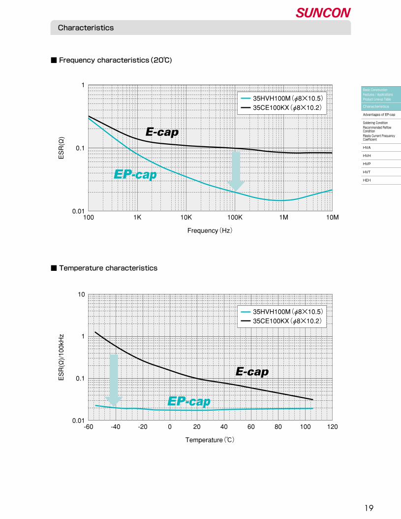
Characteristics
■ Temperature characteristics
■ Frequency characteristics(20℃)
100 1K 10K 100K 1M
1
0.1
0.0110M
Frequency(Hz)�
ESR(Ω)
35HVH100M(φ8×10.5)�35CE100KX(φ8×10.2)�
E-cap
-60 -40
10
1
0.1
0.01
Temperature(℃)�
ESR(Ω)/100kHz
-20 0 20 40 60 80 100 120
E-cap
35HVH100M(φ8×10.5)�35CE100KX(φ8×10.2)�
Basic Construction�Features / Applications�Product Line-up Table�
Characteristics�
Advantages of EP-cap�
Soldering Condition�Recommended Reflow �Condition�Ripple Current Frequency �Coefficient�
HVA�
HVH�
HVP�
HVT�
HEH
20
Advantages of
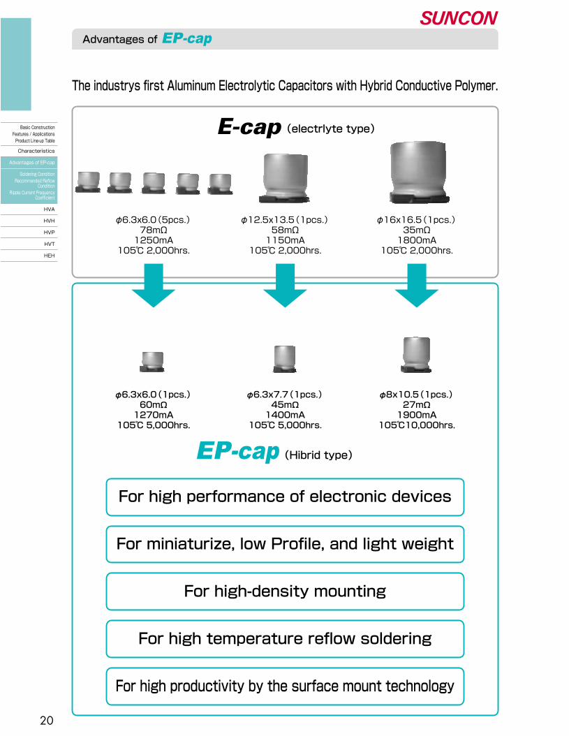
The industrys first Aluminum Electrolytic Capacitors with Hybrid Conductive Polymer.
For high performance of electronic devices
For miniaturize, low Profile, and light weight
For high-density mounting
For high temperature reflow soldering
For high productivity by the surface mount technology
(electrlyte type)�E-cap
(Hibrid type)�
φ6.3x6.0(1pcs.)�60mΩ�1270mA�
105℃ 5,000hrs.
φ8x10.5(1pcs.)�27mΩ�1900mA�
105℃10,000hrs.
φ6.3x7.7(1pcs.)�45mΩ�1400mA�
105℃ 5,000hrs.
φ6.3x6.0(5pcs.)�78mΩ�1250mA�
105℃ 2,000hrs.
φ16x16.5(1pcs.)�35mΩ�1800mA�
105℃ 2,000hrs.
φ12.5x13.5(1pcs.)�58mΩ�1150mA�
105℃ 2,000hrs.
Basic Construction�Features / Applications�Product Line-up Table�
Characteristics�
Advantages of EP-cap�
Soldering Condition�Recommended Reflow�
Condition�Ripple Current Frequency�
Coefficient�
HVA�
HVH�
HVP�
HVT�
HEH

21
Soldering Condition / Recommended Reflow Condition / Ripple Current Frequency Coefficient
■ Ripple Current Frequency Coefficient
■ Soldering Condition
■ Recommended Reflow Condition
■ Anti-vibration structure
Series Voltage�(V)�
Size Time of more than�200℃(t)�
Peak temperature�(Within 5sec.)�
HVA,HVB★ �
�
HVH,HVP,HVT
6.3 to 16�
25 to 63��
80 to 125
ALL�
φ6.3×4.5�
φ6.3×6.0 to φ10�
ALL�
�
Within 100sec.�
Within 60sec.�
Within 100sec.�
Within 100sec.
Time of more than�217℃(t1)�
Within 80sec.�
Within 50sec.�
Within 80sec.�
Within 80sec.
Time of more than�230℃(t2)�
Within 40sec.�
Within 30sec.�
Within 40sec.�
Within 40sec.
250℃�
250℃�
260℃�
250℃�
Series Capacitance : C (μF)100 ≤ F < 1k 1k ≤ F < 10k
Frequency : F (Hz)10k ≤ F < 100k 100k ≤ F < 500k
C ≤ 4.7�4.7 < C ≤ 33�33 < C�
C ≤ 10�10 < C
0.03�
0.05�
0.10�
0.03�
0.05
0.30�
0.32�
0.35�
0.20�
0.20
0.65�
0.67�
0.70�
0.50�
0.50
1.00�
1.00�
1.00�
1.00�
1.00
Available for φ8 and φ10.�[Type code]�
Capacitors can withstand two reflow processes on the above conditions. Second reflow shall be taken after more than one hour natural cooling time and taken after the return to normal temperatures of PCB board and components.
●Soldering with a soldering iron - within 350℃×3 seconds unless otherwise specified in the spec.�●Flow soldering - within 260℃×10 seconds unless otherwise specified in the spec.� (Do not apply flow soldering to SMD type.)�●Thermal curing over - ambient temperature within 150℃×2 minutes.
AIR reflow and IR reflow
preheat
Peak temperature
230
200217
150
0
190
T
Surface of external case/terminal [℃]�
Time[S]�
t max
t2 max
t1 max
HVH, HVP, HVT, HVA, HVB★ �Preheat ; 150℃ to 190℃, Within 120sec.
HV HA
Standard structure Anti-vibration structure
★�Please refer to http://www.sunelec.co.jp for the information in columns where marking is indicated in a page row.
HVH, HVP�HVT, HEH
HVA, HVB★�HEA★�
Basic Construction�Features / Applications�Product Line-up Table�
Characteristics�
Advantages of EP-cap�
Soldering Condition�Recommended Reflow �Condition�Ripple Current Frequency �Coefficient�
HVA�
HVH�
HVP�
HVT�
HEH
22
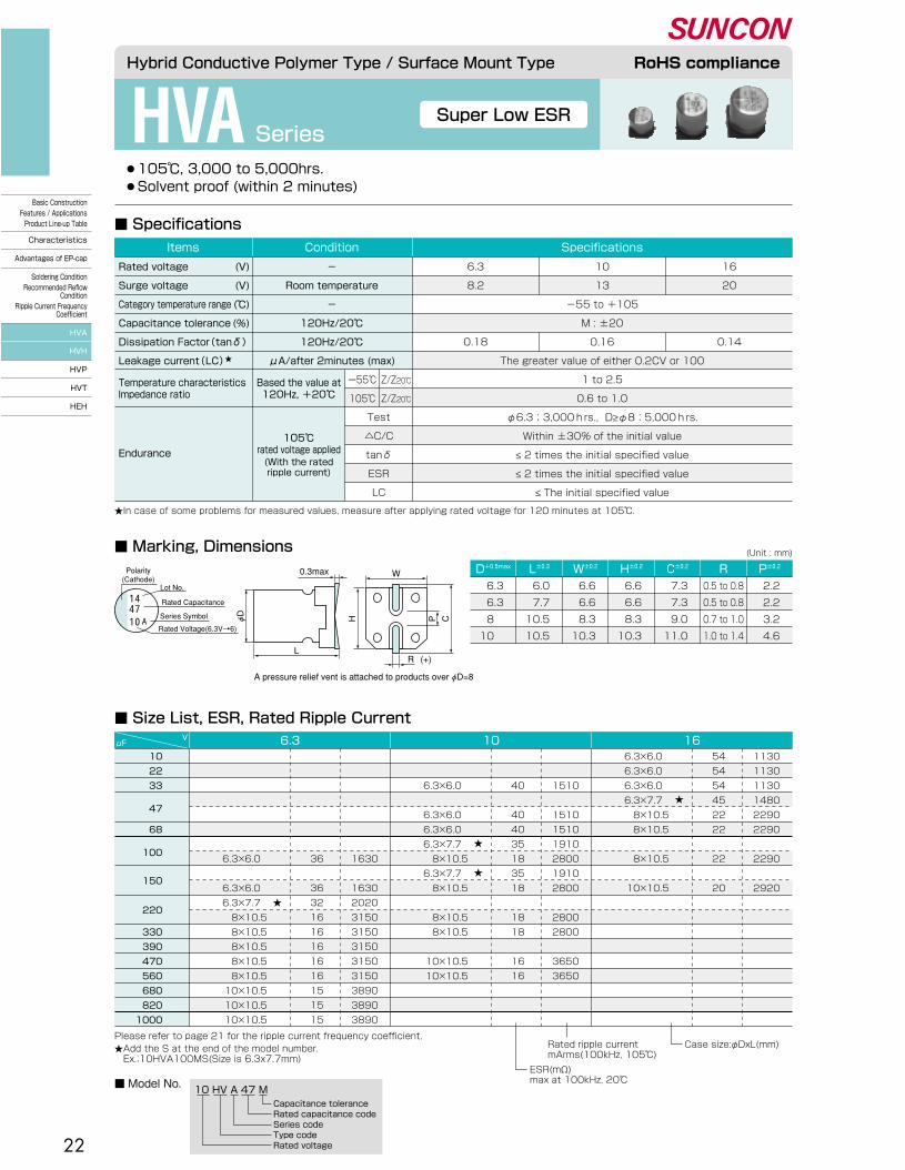
HVA Series
Hybrid Conductive Polymer Type / Surface Mount Type RoHS compliance
■ Marking, Dimensions
Please refer to page 21 for the ripple current frequency coefficient.★Add the S at the end of the model number. � Ex.;10HVA100MS(Size is 6.3x7.7mm)
Rated ripple current�mArms(100kHz, 105℃)
Case size:φDxL(mm)
ESR(mΩ)�max at 100kHz, 20℃�
10 HV A 47 MCapacitance tolerance�Rated capacitance code�Series code�Type code�Rated voltage
■ Model No.
■ Size List, ESR, Rated Ripple Current
D+0.5max W±0.2�L±0.3� H±0.2� C±0.2� R P±0.2�(Unit : mm)
6.3�
6.3�
8 �
10 �
6.0�
7.7�
10.5�
10.5
6.6�
6.6�
8.3�
10.3
6.6�
6.6�
8.3�
10.3
7.3�
7.3�
9.0�
11.0
0.5 to 0.8�
0.5 to 0.8�
0.7 to 1.0�
1.0 to 1.4
2.2�
2.2�
3.2�
4.6
■ Specifications
Endurance
105℃�rated voltage applied(With the rated�ripple current)
Temperature characteristics�Impedance ratio
Based the value at�120Hz, +20℃�
Test�
△C/C�
tanδ�
ESR�
LC
10�
13�
-55 to +105�
M : ±20�
0.16�
The greater value of either 0.2CV or 100�
1 to 2.5�
0.6 to 1.0
6.3�
8.2�
�
�
0.18
16�
20�
�
�
0.14
SpecificationsConditionItems
Rated voltage�
Surge voltage�
Category temperature range�
Capacitance tolerance�
Dissipation Factor(tanδ)�
Leakage current(LC)★�
(V)�
(V)�
(℃)�
(%)
-�
Room temperature�
-�
120Hz/20℃�
120Hz/20℃�
μA/after 2minutes (max)
φ6.3;3,000hrs., D≥φ8;5,000hrs.�
Within ±30% of the initial value�
≤ 2 times the initial specified value�
≤ 2 times the initial specified value�
≤ The initial specified value
1447
A10
Polarity�(Cathode)
Lot No.
Rated Capacitance
Series Symbol
Rated Voltage(6.3V→6)
0.3max
L
W
(+)R
φD��
H� � P C
A pressure relief vent is attached to products over φD=8
Super Low ESR
●105℃, 3,000 to 5,000hrs.� ●Solvent proof (within 2 minutes)
ー55℃�
105℃�
Z/Z20℃�
Z/Z20℃�
★In case of some problems for measured values, measure after applying rated voltage for 120 minutes at 105℃.
10�
22�
33�
47��
68�
100��
150��
220��
330�
390�
470�
560�
680�
820�
1000
μFV 6.3 10 16
6.3×6.0 �
6.3×6.0 �
6.3×6.0 �
6.3×7.7 �
8×10.5�
8×10.5�
�
8×10.5�
�
10×10.5
1130�
1130�
1130�
1480�
2290�
2290�
�
2290�
�
2920
54�
54�
54�
45�
22�
22�
�
22�
�
20
�
�
6.3×6.0 �
�
6.3×6.0 �
6.3×6.0 �
6.3×7.7 �
8×10.5�
6.3×7.7 �
8×10.5�
�
8×10.5�
8×10.5�
�
10×10.5�
10×10.5
�
�
1510�
�
1510�
1510�
1910�
2800�
1910�
2800�
�
2800�
2800�
�
3650�
3650
�
�
40�
�
40�
40�
35�
18�
35�
18�
�
18�
18�
�
16�
16
�
�
�
�
�
�
�
6.3×6.0 �
�
6.3×6.0 �
6.3×7.7 �
8×10.5�
8×10.5�
8×10.5�
8×10.5�
8×10.5�
10×10.5�
10×10.5�
10×10.5
★�
★�
�
★�
★�
�
�
�
�
�
�
�
1630�
�
1630�
2020�
3150�
3150�
3150�
3150�
3150�
3890�
3890�
3890
�
�
�
�
�
�
�
36�
�
36�
32�
16�
16�
16�
16�
16�
15�
15�
15
Basic Construction�Features / Applications�Product Line-up Table�
Characteristics�
Advantages of EP-cap�
Soldering Condition�Recommended Reflow�
Condition�Ripple Current Frequency�
Coefficient�
HVA�
HVH�
HVP�
HVT�
HEH
23
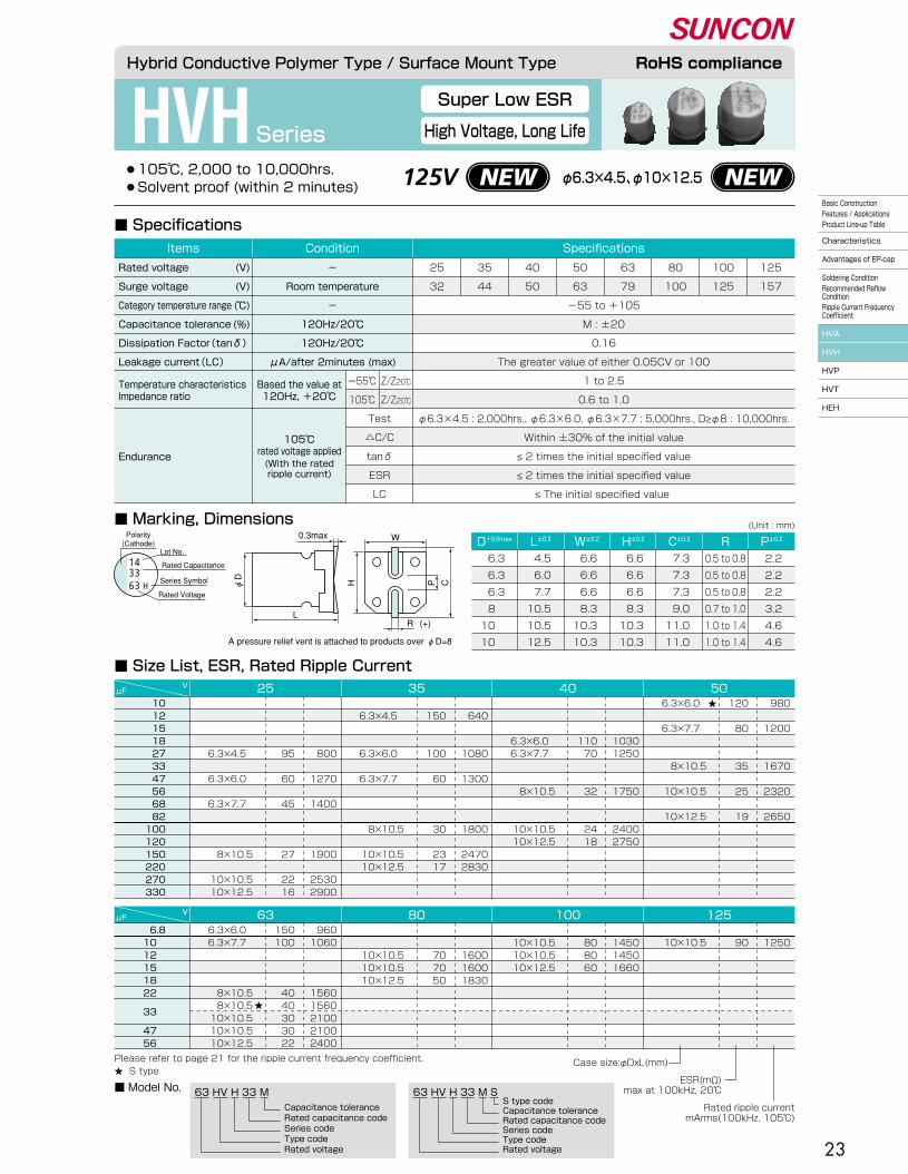
HVHSeries
■ Marking, Dimensions
■ Specifications
63 HV H 33 M
Capacitance tolerance�Rated capacitance code�Series code�Type code�Rated voltage
63 HV H 33 M SS type code�Capacitance tolerance�Rated capacitance code�Series code�Type code�Rated voltage
■ Model No.
■ Size List, ESR, Rated Ripple Current
(Unit : mm)
Super Low ESR
High Voltage, Long Life
Please refer to page 21 for the ripple current frequency coefficient.�★ S type
●105℃, 2,000 to 10,000hrs.� ●Solvent proof (within 2 minutes)
Hybrid Conductive Polymer Type / Surface Mount Type RoHS compliance
Endurance
105℃�rated voltage applied(With the rated�ripple current)
Temperature characteristics�Impedance ratio
Based the value at�120Hz, +20℃�
Test�
△C/C�
tanδ�
ESR�
LC
ー55℃�
105℃�
Z/Z20℃�
Z/Z20℃�
�
�
-55 to +105�
M : ±20�
0.16�
The greater value of either 0.05CV or 100�
1 to 2.5�
0.6 to 1.0
SpecificationsConditionItems
Rated voltage�
Surge voltage�
Category temperature range�
Capacitance tolerance�
Dissipation Factor(tanδ)�
Leakage current(LC)�
(V)�
(V)�
(℃)�
(%)
-�
Room temperature�
-�
120Hz/20℃�
120Hz/20℃�
μA/after 2minutes (max)
φ6.3×4.5 : 2,000hrs., φ6.3×6.0, φ6.3×7.7 : 5,000hrs., D≥φ8 : 10,000hrs.�
Within ±30% of the initial value�
≤ 2 times the initial specified value�
≤ 2 times the initial specified value�
≤ The initial specified value
Polarity�(Cathode)
Lot No.
Rated Capacitance
Series Symbol
Rated Voltage
0.3max
L
W
(+)R
φD�� H� � P C
A pressure relief vent is attached to products over φD=8
6333
H
14
25�
32
35�
44
40�
50
50�
63
63�
79
80�
100
125�
157
100�
125
D+0.5max W±0.2�L±0.3� H±0.2� C±0.2� R P±0.2�
6.3�
6.3�
6.3�
8 �
10 �
10 �
4.5�
6.0�
7.7�
10.5�
10.5�
12.5
6.6�
6.6�
6.6�
8.3�
10.3�
10.3
6.6�
6.6�
6.6�
8.3�
10.3�
10.3
7.3�
7.3�
7.3�
9.0�
11.0�
11.0
0.5 to 0.8�
0.5 to 0.8�
0.5 to 0.8�
0.7 to 1.0�
1.0 to 1.4�
1.0 to 1.4
2.2�
2.2�
2.2�
3.2�
4.6�
4.6
10�12�15�18�27�33�47�56�68�82�100�120�150�220�270�330
μFV 25 35 40 50
6.3×6.0 ��
6.3×7.7 ���
8×10.5��
10×10.5��
10×12.5
980��
1200���
1670��
2320��
2650
120��
80���
35��
25��
19
���
6.3×6.0 �6.3×7.7 �
��
8×10.5���
10×10.5�10×12.5
���
1030�1250�
��
1750���
2400�2750
���
110�70���
32���
24�18
�6.3×4.5 �
��
6.3×6.0 ��
6.3×7.7 ����
8×10.5��
10×10.5�10×12.5
�640�
��
1080��
1300����
1800��
2470�2830
�150�
��
100��
60����
30��
23�17
����
6.3×4.5 ��
6.3×6.0 ��
6.3×7.7 ����
8×10.5��
10×10.5�10×12.5
����
800��
1270��
1400����
1900��
2530�2900
����
95��
60��
45����
27��
22�16
6.8�10 �12 � 15 �18 �22 �
33 ��
47 �56 �
μFV 63 80 100
6.3×6.0 �6.3×7.7 �
���
8×10.5�8×10.5�10×10.5�10×10.5�10×12.5
960�1060�
���
1560�1560�2100�2100�2400
150�100�
���
40�40�30�30�22
�10×10.5�10×10.5�10×12.5
�1450�1450�1660
�80�80�60
��
10×10.5�10×10.5�10×12.5
��
1600�1600�1830
��
70�70�50
125�
10×10.5�
1250�
90
★�
★�
Case size:φDxL(mm)
Rated ripple current�mArms(100kHz, 105℃)
ESR(mΩ)�max at 100kHz, 20℃�
φ6.3×4.5、φ10×12.5125VBasic Construction�Features / Applications�Product Line-up Table�
Characteristics�
Advantages of EP-cap�
Soldering Condition�Recommended Reflow �Condition�Ripple Current Frequency �Coefficient�
HVA�
HVH�
HVP�
HVT�
HEH
24
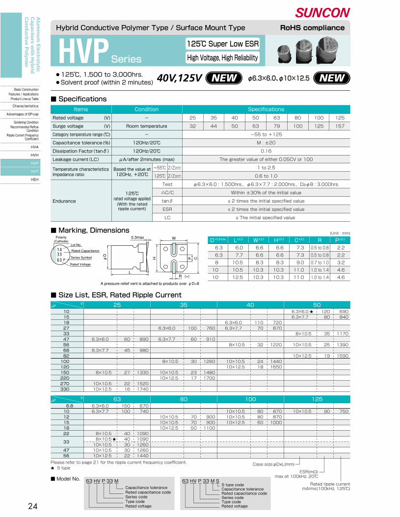
HVPSeries
●125℃, 1,500 to 3,000hrs.� ●Solvent proof (within 2 minutes)
■ Marking, Dimensions
■ Specifications
■ Size List, ESR, Rated Ripple Current
(Unit : mm)
■ Model No.
125℃ Super Low ESR
High Voltage, High Reliability
Hybrid Conductive Polymer Type / Surface Mount Type RoHS compliance
Endurance
125℃�rated voltage applied(With the rated�ripple current)
Temperature characteristics�Impedance ratio
Based the value at�120Hz, +20℃�
Test�
△C/C�
tanδ�
ESR�
LC
�
�
-55 to +125�
M : ±20�
0.16�
The greater value of either 0.05CV or 100�
1 to 2.5�
0.6 to 1.0
SpecificationsConditionItems
Rated voltage�
Surge voltage�
Category temperature range�
Capacitance tolerance�
Dissipation Factor(tanδ)�
Leakage current(LC)�
(V)�
(V)�
(℃)�
(%)
-�
Room temperature�
-�
120Hz/20℃�
120Hz/20℃�
μA/after 2minutes (max)
φ6.3×6.0 : 1,500hrs., φ6.3×7.7 : 2,000hrs., D≥φ8 : 3,000hrs.�
Within ±30% of the initial value�
≤ 2 times the initial specified value�
≤ 2 times the initial specified value�
≤ The initial specified value
0.3max
L
W
(+)R
φD��
H� � P C
A pressure relief vent is attached to products over φD=8
Polarity�(Cathode)
Lot No.
Rated Capacitance
Series Symbol
Rated Voltage6333
P
14
ー55℃�
125℃�
Z/Z20℃�
Z/Z20℃�
63 HV P 33 M
Capacitance tolerance�Rated capacitance code�Series code�Type code�Rated voltage
63 HV P 33 M SS type code�Capacitance tolerance�Rated capacitance code�Series code�Type code�Rated voltage
25�
32
35�
44
50�
63
63�
79
80�
100
125�
157
40�
50
100�
125
D+0.5max W±0.2�L±0.3� H±0.2� C±0.2� R P±0.2�
6.3�
6.3�
8 �
10 �
10 �
6.0�
7.7�
10.5�
10.5�
12.5
6.6�
6.6�
8.3�
10.3�
10.3
6.6�
6.6�
8.3�
10.3�
10.3
7.3�
7.3�
9.0�
11.0�
11.0
0.5 to 0.8�
0.5 to 0.8�
0.7 to 1.0�
1.0 to 1.4�
1.0 to 1.4
2.2�
2.2�
3.2�
4.6�
4.6
μFV 25 35 40
6.8�10 �12 �15 �18 �22 �
33 ��
47 �56 �
μFV 63 80 100
�10×10.5�10×10.5�10×12.5
�870�870�1000
�80�80�60
��
10×10.5�10×10.5�10×12.5
��
900�900�1100
��
70�70�50
6.3×6.0 �6.3×7.7 �
���
8×10.5�8×10.5�10×10.5�10×10.5�10×12.5
670�740�
���
1090�1090�1260�1260�1440
150�100�
���
40�40�30�30�22
10 �15 �18 �27 �33 �47 �56 �68 �82 �100 �120 �150 �220 �270 �330 �
��
6.3×6.0 �6.3×7.7 �
��
8×10.5���
10×10.5�10×12.5
��
720�870�
��
1220���
1440�1650
��
110�70���
32���
24�18
50
125�
10×10.5�
750�
90
6.3×6.0 �6.3×7.7 �
��
8×10.5��
10×10.5��
10×12.5
690�840�
��
1170��
1390��
1590
120�80���
35��
25��
19
���
6.3×6.0 ��
6.3×7.7 ����
8×10.5��
10×10.5�10×12.5
���
760��
910����
1260��
1480�1700
���
100��
60����
30��
23�17
�����
6.3×6.0 ��
6.3×7.7 ����
8×10.5��
10×10.5�10×12.5
�����
890��
980����
1330��
1520�1740
�����
60��
45����
27��
22�16
★�
★�
Case size:φDxL(mm)
Rated ripple current�mArms(100kHz, 125℃)
ESR(mΩ)�max at 100kHz, 20℃�
Please refer to page 21 for the ripple current frequency coefficient.�★ S type
40V,125V φ6.3×6.0、φ10×12.5
Alu
min
um
Electro
lytic C
apacito
rs with
Hyb
rid
Co
nd
uctive P
olym
er
Basic Construction�Features / Applications�Product Line-up Table�
Characteristics�
Advantages of EP-cap�
Soldering Condition�Recommended Reflow�
Condition�Ripple Current Frequency�
Coefficient�
HVA�
HVH�
HVP�
HVT�
HEH

25
63 HV T 33 M
Capacitance tolerance�Rated capacitance code�Series code�Type code�Rated voltage
63 HV T 33 M SS type code�Capacitance tolerance�Rated capacitance code�Series code�Type code�Rated voltage
Please refer to page 21 for the ripple current frequency coefficient.�★ S type
HVT Series
Hybrid Conductive Polymer Type / Surface Mount Type RoHS compliance
■ Marking, Dimensions
■ Specifications
■ Model No.
■ Size List, ESR, Rated Ripple Current
(Unit : mm)
Endurance
135℃�rated voltage applied(With the rated�ripple current)
Temperature characteristics�Impedance ratio
Based the value at�120Hz, +20℃�
Test�
△C/C�
tanδ�
ESR�
LC
ー55℃�
135℃�
Z/Z20℃�
Z/Z20℃�
�
�
-55 to +135�
M : ±20�
0.16�
The greater value of either 0.05CV or 100�
1 to 2.5�
0.6 to 1.0
25�
32
35�
44
50�
63
40�
50
63�
79
SpecificationsConditionItems
Rated voltage�
Surge voltage�
Category temperature range�
Capacitance tolerance�
Dissipation Factor(tanδ)�
Leakage current(LC)�
(V)�
(V)�
(℃)�
(%)
-�
Room temperature�
-�
120Hz/20℃�
120Hz/20℃�
μA/after 2minutes (max)
φ6.3 : 1,000hrs., D≥φ8 : 2,000hrs.�
Within ±30% of the initial value�
≤ 2 times the initial specified value�
≤ 2 times the initial specified value�
≤ The initial specified value
135℃ guaranteed
●135℃, 1,000 to 2,000hrs.� ●Solvent proof (within 2 minutes)
Polarity�(Cathode)
Lot No.
Rated Capacitance
Series Symbol
Rated Voltage6333
T
14
0.3max
L
W
(+)R
φD
H P C
D+0.5max W±0.2� H±0.2� C±0.2�L±0.3� R P±0.2�
7.7�
10.5�
10.5�
12.5
6.6�
8.3�
10.3�
10.3
6.6�
8.3�
10.3�
10.3
7.3�
9.0�
11.0�
11.0
0.5 to 0.8�
0.7 to 1.0�
1.0 to 1.4�
1.0 to 1.4
2.2�
3.2�
4.6�
4.6
6.3�
8 �
10 �
10 �
μFV 25 35 40 50
15�
27�
33�
47�
56�
68�
82�
100�
120�
150�
220�
270�
330
670�
�
940�
�
1110�
�
1270
80�
�
35�
�
25�
�
19
�
700�
�
�
980�
�
�
1150�
1320
�
70�
�
�
32�
�
�
24�
18
�
�
�
730�
�
�
�
1010�
�
1180�
1360
�
�
�
60�
�
�
�
30�
�
23�
17
�
�
�
�
�
780�
�
�
�
1060�
�
1220�
1390
�
�
�
�
�
45�
�
�
�
27�
�
22�
16
�
�
�
6.3×7.7 �
�
�
�
8×10.5�
�
10×10.5�
10×12.5
�
6.3×7.7 �
�
�
8×10.5�
�
�
10×10.5�
10×12.5
6.3×7.7 �
�
8×10.5�
�
10×10.5�
�
10×12.5
�
�
�
�
�
6.3×7.7 �
�
�
�
8×10.5�
�
10×10.5�
10×12.5
μFV 63
10�
22�
33��
47�
56
590�
870�
870�
1010�
1010�
1150
100�
40�
40�
30�
30�
22
6.3×7.7 �
8×10.5�
8×10.5�
10×10.5�
10×10.5�
10×12.5
Rated ripple current�mArms(100kHz, 135℃)
Case size:φDxL(mm)
ESR(mΩ)�max at 100kHz, 20℃�
★�
40V φ6.3×7.7、φ10×12.5
A pressure relief vent is attached to products over φD=8
Alu
min
um
Electro
lytic C
apacito
rs with
Hyb
rid
Co
nd
uctive P
olym
er
Basic Construction�Features / Applications�Product Line-up Table�
Characteristics�
Advantages of EP-cap�
Soldering Condition�Recommended Reflow �Condition�Ripple Current Frequency �Coefficient�
HVA�
HVH�
HVP�
HVT�
HEH

26
HEHSeries
■ Specifications
■ Model No.
■ Size List, ESR, Rated Ripple Current
(Unit : mm)
Super Low ESR
High Voltage, Long Life
●105℃, 10,000hrs. ● Laminated aluminum case� ●Solvent proof (within 2 minutes)
Hybrid Conductive Polymer Type / Radial Lead Type RoHS compliance
Endurance
105℃ 10,000hrs.�rated voltage applied(With the rated�ripple current)
Temperature characteristics�Impedance ratio
Based the value at�120Hz, +20℃�
△C/C�
tanδ�
ESR�
LC
ー55℃�
105℃�
Z/Z20℃�
Z/Z20℃�
�
�
-55 to +105�
M : ±20�
0.16�
The greater value of either 0.05CV or 100�
1 to 2.5�
0.6 to 1.0
25�
32
35�
44
40�
50
50�
63
63�
79
80�
100
100�
125
SpecificationsConditionItems
Rated voltage�
Surge voltage�
Category temperature range�
Capacitance tolerance�
Dissipation Factor(tanδ)�
Leakage current(LC)�
(V)�
(V)�
(℃)�
(%)
-�
Room temperature�
-�
120Hz/20℃�
120Hz/20℃�
μA/after 2minutes (max)
Within ±30% of the initial value�
≤ 2 times the initial specified value�
≤ 2 times the initial specified value�
≤ The initial specified value
■ Marking, Dimensions
6333
H
14T
Polarity�(Cathode)
Lot No.
Rated Capacitance
Series Symbol
Rated Voltage
φd±0.05
15min20min
5min
φD+0.5max
L+1.5max
F±0.5
pressure relief vent(φD=10)
φD FL φd8�
10�
10
9.5�
9.5�
11.5
3.5�
5.0�
5.0
0.6�
0.7�
0.7
63 HE H 33 M TSn plating terminal code�Capacitance tolerance�Rated capacitance code�Series code�Type code�Rated voltage
63 HE H 33 M S TSn plating terminal code�S type code�Capacitance tolerance�Rated capacitance code�Series code�Type code�Rated voltage
33�
56�
82�
100�
120�
150�
220�
270�
330
μFV 25 35 40 50
8×9.5 �
10×9.5 �
10×11.5
1670�
2320�
2650
35�
25�
19
�
8×9.5 �
�
10×9.5 �
10×11.5
�
1750�
�
2400�
2750
�
32�
�
24�
18
�
�
�
8×9.5 �
�
10×9.5 �
10×11.5
�
�
�
1800�
�
2470�
2830
�
�
�
30�
�
23�
17
�
�
�
�
�
8×9.5 �
�
10×9.5 �
10×11.5
�
�
�
�
�
1900�
�
2530�
2900
�
�
�
�
�
27�
�
22�
16
10�
12�
15�
18�
22�
33�
47�
56
μFV 63 80 100
�
�
�
�
8×9.5 �
8×9.5 �
10×9.5 �
10×9.5 �
10×11.5
�
�
�
�
1560�
1560�
2100�
2100�
2400
�
�
�
�
40�
40�
30�
30�
22
10×9.5 �
10×9.5 �
10×11.5
1450�
1450�
1660
80�
80�
60
�
10×9.5 �
10×9.5 �
10×11.5
�
1600�
1600�
1830
�
70�
70�
50
Please refer to page 21 for the ripple current frequency coefficient.★S type Rated ripple current�
mArms(100kHz, 105℃)
Case size:φDxL(mm)
ESR(mΩ)max at 100kHz, 20℃�
★�
Alu
min
um
Electro
lytic C
apacito
rs with
Hyb
rid
Co
nd
uctive P
olym
er
Basic Construction�Features / Applications�Product Line-up Table�
Characteristics�
Advantages of EP-cap�
Soldering Condition�Recommended Reflow�
Condition�Ripple Current Frequency�
Coefficient�
HVA�
HVH�
HVP�
HVT�
HEH

27
Aluminum Electrolytic Capacitors is�hard to be in Short-mode because, �it has Shelf-healing mechanism at the dielectric�layer by its electrolyte.�Aluminum Electrolytic Capacitors supply wide�range of capacitance and voltage. �They are suitable for econmical circuit design.
Aluminum Electrolytic Capacitors
Features
● Wide rated voltage range from 4V to 450V�
● Wide capacitance range from 0.47μF to 15000μF�
● Self healing of the dielectrics� (aluminium oxide film ) after damages.�
● The main failuremode is of wear-out.� Short circuit within capacitor is not appreciable. �
● No voltage dependence of capacitance.�
● Can withstand applied pulse current and pulse voltage � compared to other types of capacitors. ��Applications
Automotive electric, Network equipment, Industrial equipment, �Digital equipment, Consumer equipment, PC etc.
CE-BJ�
CE-BE�
CE-BD�
CE-BSS�
CE-BS�
CE-FE�
CE-FD�
CE-LD�
CE-FSS�
CE-FU�
CE-FS�
CE-FH�
CE-GA�
CE-AX�
CE-KX�
CE-LX�
CE-LS�
CE-LH�
CE-LL�
CE-PC�
CE-PH�
CE-NP�
CE-FN�
ME-SWB�
ME-UZ・SZ�
ME-UAX・SAX�
ME-LS�
ME-HC�
ME-CZ�
ME-CA�
ME-CX�
ME-AX�
ME-WX�
ME-WA�
ME-WL�
ME-SWG�
ME-WG�
ME-PX�
ME-HPC・HPD�
ME-FC・FD�
ME-FAZ�
ME-FH�
ME-SWN�
ME-HWN

28
●Solvent proof (within 2 minutes)
10�
15�
22�
33�
47�
68�
82
�
�
�
�
�
�
6.3×3.25
�
�
�
�
�
�
60
4
16 CE 33 BJ
μFV 6.3 10 16 25 35 50
�
�
�
�
�
6.3×3.25
�
�
�
�
6.3×3.25
�
�
�
6.3×3.25
�
�
6.3×3.25
�
6.3×3.25
6.3×3.25�
�
�
�
�
60
�
�
�
�
51
�
�
�
46
�
�
46
�
44
31
Series code�Rated capacitance code�Type code�Rated voltage
Rated ripple current�mArms(120Hz, 85℃)
Case size:φDxL(mm)
CE-BJ Series
Super Low Profile
3.25mm Height
3.256.3
D+0.5max W±0.2� H±0.2� C±0.2� R P±0.2�
6.6 6.6 7.3 0.5 to 0.8 2.2
L +0.1�-0.2�
Aluminum Electrolytic Type / Surface Mount Type RoHS compliance
■ Specifications
■ Marking, Dimensions
■ Size List, Rated Ripple Current
■ Model No.
Please refer to page 15 for the ripple current frequency coefficient.
(Unit : mm)
1433
J16
Polarity�(Cathode)
Lot No.
Rated Capacitance
Series Symbol
Rated Voltage(6.3V→6)
0.3max
L
W
(+)R
φD H� � P C
Endurance
85℃, 1,000hrs.�rated voltage applied
Based the value at�120Hz, +20℃�
(With the rated�ripple current)
Impedance ratio at�low temperature
�
△C/C�
tanδ�
LC
ー25℃�
ー40℃�
Z/Z20℃�
Z/Z20℃�
16�
20�
-40 to +85�
M : ±20�
0.20�
0.01CV�
2�
6
4�
5.0�
�
�
0.40�
�
7�
15
6.3�
8.0�
�
�
0.35�
�
4�
10
10�
13�
�
�
0.24�
�
3�
8
25�
32�
�
�
0.16�
�
2�
4
35�
44�
�
�
0.14�
�
2�
4
50�
63�
�
�
0.12�
�
2�
4
SpecificationsConditionItems
Rated voltage�
Surge voltage�
Category temperature range�
Capacitance tolerance�
Dissipation Factor(tanδ)�
Leakage current(LC)�
(V)�
(V)�
(℃)�
(%)
-�
Room temperature�
-�
120Hz/20℃�
120Hz/20℃�
μA/after 2minutes (max)
Within ±25% of the initial value�
≤ 2 times the initial specified value�
≤ The initial specified value
Alu
min
um
Electro
lytic C
apacito
rs
CE-BJ�
CE-BE�
CE-BD�
CE-BSS�
CE-BS�
CE-FE�
CE-FD�
CE-LD�
CE-FSS�
CE-FU�
CE-FS�
CE-FH�
CE-GA�
CE-AX�
CE-KX�
CE-LX�
CE-LS�
CE-LH�
CE-LL�
CE-PC�
CE-PH�
CE-NP�
CE-FN�
ME-SWB�
ME-UZ・SZ�
ME-UAX・SAX�
ME-LS�
ME-HC�
ME-CZ�
ME-CA�
ME-CX�
ME-AX�
ME-WX�
ME-WA�
ME-WL�
ME-SWG�
ME-WG�
ME-PX�
ME-HPC・HPD�
ME-FC・FD�
ME-FAZ�
ME-FH�
ME-SWN�
ME-HWN

29
16 CE 22 BE
Series code�Rated capacitance code�Type code�Rated voltage
16 CE 22 BESBE series BES series
Series code�Rated capacitance code�Type code�Rated voltage
Please refer to page 15 for the ripple current frequency coefficient.�★BES series
●Solvent proof (within 2 minutes)
CE-BESeries
Miniature Low Profile
3.9mm Height
D+0.5max W±0.2� H±0.2� C±0.2� R P±0.2�L +0.1�-0.2�
(Unit : mm)
5 �
6.3
3.9�
3.9
5.3�
6.6
5.3�
6.6
6.0�
7.3
0.5 to 0.8�
0.5 to 0.8
1.4�
2.2
Aluminum Electrolytic Type / Surface Mount Type RoHS compliance
■ Specifications
■ Marking, Dimensions
■ Size List, Rated Ripple Current
■ Model No.
Endurance
85℃, 1,000hrs.�rated voltage applied(With the rated�ripple current)
△C/C�
tanδ�
LC
16�
20�
-40 to +85�
M : ±20�
0.20�
The greater value of either 0.01CV or 3�
2�
6
4�
5.0�
�
�
0.40�
�
7�
15
6.3�
8.0�
�
�
0.30�
�
4�
10
10�
13�
�
�
0.24�
�
3�
8
25�
32�
�
�
0.16�
�
2�
4
35�
44�
�
�
0.14�
�
2�
4
50�
63�
�
�
0.12�
�
2�
4
SpecificationsConditionItems
Rated voltage�
Surge voltage�
Category temperature range�
Capacitance tolerance�
Dissipation Factor(tanδ)�
Leakage current(LC)�
(V)�
(V)�
(℃)�
(%)
-�
Room temperature�
-�
120Hz/20℃�
120Hz/20℃�
μA/after 2minutes (max)
Within ±25% of the initial value�
≤ 2 times the initial specified value�
≤ The initial specified value
Based the value at�120Hz, +20℃�
Impedance ratio at�low temperature
ー25℃�
ー40℃�
Z/Z20℃�
Z/Z20℃�
1422
E16
Polarity�(Cathode)
Lot No.
Rated Capacitance
Series Symbol
Rated Voltage(6.3V→6)
0.3max
L
W
(+)R
φD��
H� � P C
1.0�
2.2�
3.3�
4.7�
10 �
22 ��
33 �
�
47 �
�
68 �
�
100 �
�180
4μFV 6.3 10 16 25 35 50
5×3.9�
5×3.9�
5×3.9�
5×3.9�
6.3×3.9
8.4�
14 �
17 �
21 �
33 �
�
�
�
5×3.9�
5×3.9�
�
6.3×3.9
�
�
�
18�
29�
�
49
�
�
�
18�
30�
�
50�
�
60
�
�
�
�
25�
37�
45�
�
50�
�
60
�
�
�
�
�
�
35�
43�
50�
�
55
�
�
�
�
�
�
33�
�
40�
48�
60�
�
70�
�
75
�
�
�
�
�
�
�
�
33�
�
40�
48�
60�
58�
70�
85
�
�
�
5×3.9�
5×3.9�
�
6.3×3.9�
�
6.3×3.9
�
�
�
�
5×3.9 �
5×3.9★�
6.3×3.9 �
�
6.3×3.9 �
�
6.3×3.9 �
�
�
�
�
�
�
5×3.9 �
5×3.9★�
6.3×3.9 �
�
6.3×3.9 �
�
�
�
�
�
�
5×3.9 �
�
5×3.9 �
5×3.9★�
6.3×3.9 �
�
6.3×3.9 �
�
6.3×3.9 �
�
�
�
�
�
�
�
�
5×3.9 �
�
5×3.9 �
5×3.9★�
6.3×3.9 �
5×3.9★�
6.3×3.9 �
6.3×3.9 �
Rated ripple current�mArms(120Hz, 85℃)
Case size:φDxL(mm)
Alu
min
um
Electro
lytic C
apacito
rs
CE-BJ�
CE-BE�
CE-BD�
CE-BSS�
CE-BS�
CE-FE�
CE-FD�
CE-LD�
CE-FSS�
CE-FU�
CE-FS�
CE-FH�
CE-GA�
CE-AX�
CE-KX�
CE-LX�
CE-LS�
CE-LH�
CE-LL�
CE-PC�
CE-PH�
CE-NP�
CE-FN�
ME-SWB�
ME-UZ・SZ�
ME-UAX・SAX�
ME-LS�
ME-HC�
ME-CZ�
ME-CA�
ME-CX�
ME-AX�
ME-WX�
ME-WA�
ME-WL�
ME-SWG�
ME-WG�
ME-PX�
ME-HPC・HPD�
ME-FC・FD�
ME-FAZ�
ME-FH�
ME-SWN�
ME-HWN
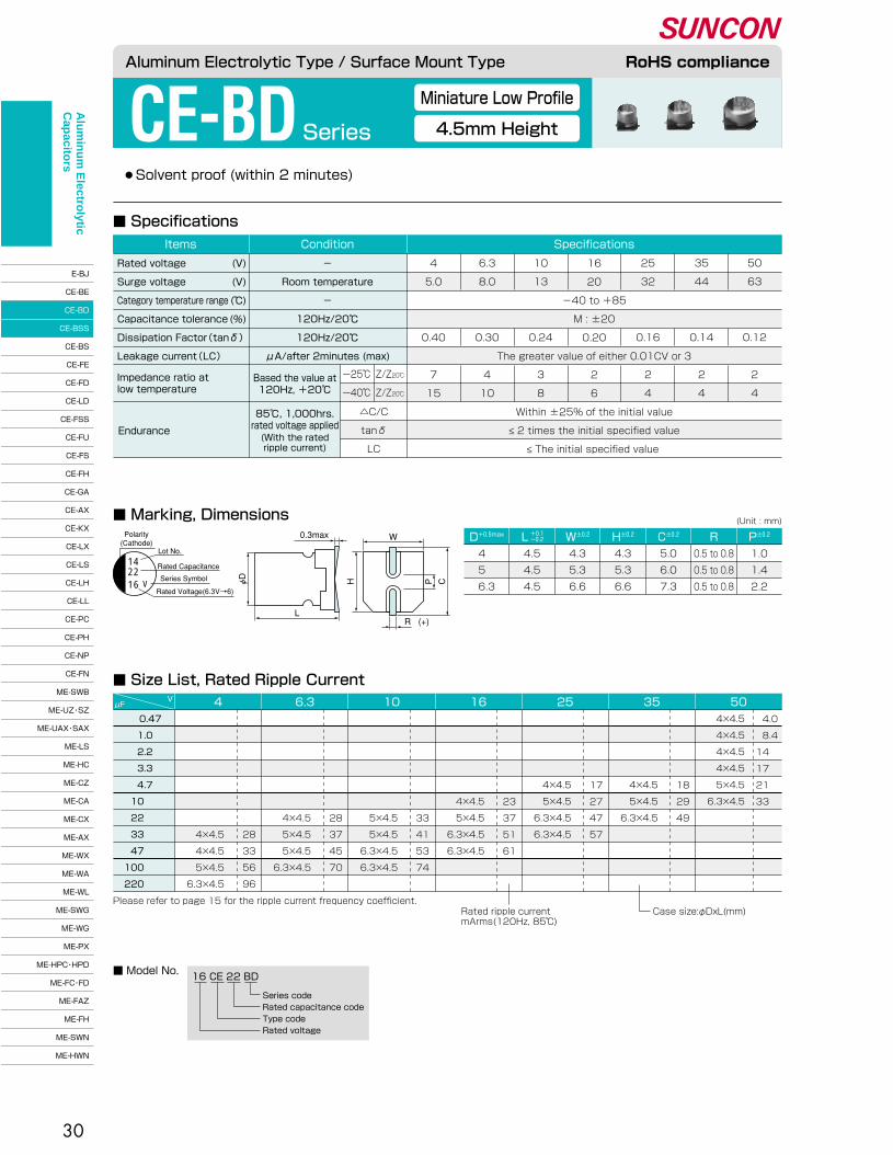
30
●Solvent proof (within 2 minutes)
CE-BDSeries
■ Specifications
■ Marking, Dimensions
16 CE 22 BD
Series code�Rated capacitance code�Type code�Rated voltage
0.47�
1.0 �
2.2 �
3.3 �
4.7 �
10 �
22 �
33 �
47 �
100 �
220
�
�
�
�
�
�
�
28�
33�
56�
96
4μFV 6.3 10 16 25 35 50
4×4.5�
4×4.5�
4×4.5�
4×4.5�
5×4.5�
6.3×4.5
�
�
�
�
4×4.5�
5×4.5�
6.3×4.5
�
�
�
�
4×4.5�
5×4.5�
6.3×4.5�
6.3×4.5
�
�
�
�
�
4×4.5�
5×4.5�
6.3×4.5�
6.3×4.5
�
�
�
�
�
�
5×4.5�
5×4.5�
6.3×4.5�
6.3×4.5
�
�
�
�
�
�
4×4.5�
5×4.5�
5×4.5�
6.3×4.5
�
�
�
�
�
�
�
4×4.5�
4×4.5�
5×4.5�
6.3×4.5
�
�
�
�
�
�
28�
37�
45�
70
�
�
�
�
�
�
33�
41�
53�
74
�
�
�
�
�
23�
37�
51�
61
�
�
�
�
17�
27�
47�
57
�
�
�
�
18�
29�
49
4.0�
8.4�
14 �
17 �
21 �
33 �
Please refer to page 15 for the ripple current frequency coefficient.Rated ripple current�mArms(120Hz, 85℃)
Case size:φDxL(mm)
■ Size List, Rated Ripple Current
■ Model No.
D+0.5max W±0.2� H±0.2� C±0.2� R P±0.2�L +0.1�-0.2�
(Unit : mm)
4 �
5 �
6.3
4.5�
4.5�
4.5
4.3�
5.3�
6.6
4.3�
5.3�
6.6
5.0�
6.0�
7.3
0.5 to 0.8�
0.5 to 0.8�
0.5 to 0.8
1.0�
1.4�
2.2
Miniature Low Profile
4.5mm Height
Aluminum Electrolytic Type / Surface Mount Type RoHS compliance
16
Polarity�(Cathode)
Lot No.
Rated Capacitance
Series Symbol
Rated Voltage(6.3V→6)
0.3max
L
W
(+)R
φD��
H� � P C
1422
V
Endurance
85℃, 1,000hrs.�rated voltage applied(With the rated�ripple current)
△C/C�
tanδ�
LC
16�
20�
-40 to +85�
M : ±20�
0.20�
The greater value of either 0.01CV or 3�
2�
6
4�
5.0�
�
�
0.40�
�
7�
15
6.3�
8.0�
�
�
0.30�
�
4�
10
10�
13�
�
�
0.24�
�
3�
8
25�
32�
�
�
0.16�
�
2�
4
35�
44�
�
�
0.14�
�
2�
4
50�
63�
�
�
0.12�
�
2�
4
SpecificationsConditionItems
Rated voltage�
Surge voltage�
Category temperature range�
Capacitance tolerance�
Dissipation Factor(tanδ)�
Leakage current(LC)�
(V)�
(V)�
(℃)�
(%)
-�
Room temperature�
-�
120Hz/20℃�
120Hz/20℃�
μA/after 2minutes (max)
Within ±25% of the initial value�
≤ 2 times the initial specified value�
≤ The initial specified value
Based the value at�120Hz, +20℃�
Impedance ratio at�low temperature
ー25℃�
ー40℃�
Z/Z20℃�
Z/Z20℃�
Alu
min
um
Electro
lytic C
apacito
rs
CE-BJ�
CE-BE�
CE-BD�
CE-BSS�
CE-BS�
CE-FE�
CE-FD�
CE-LD�
CE-FSS�
CE-FU�
CE-FS�
CE-FH�
CE-GA�
CE-AX�
CE-KX�
CE-LX�
CE-LS�
CE-LH�
CE-LL�
CE-PC�
CE-PH�
CE-NP�
CE-FN�
ME-SWB�
ME-UZ・SZ�
ME-UAX・SAX�
ME-LS�
ME-HC�
ME-CZ�
ME-CA�
ME-CX�
ME-AX�
ME-WX�
ME-WA�
ME-WL�
ME-SWG�
ME-WG�
ME-PX�
ME-HPC・HPD�
ME-FC・FD�
ME-FAZ�
ME-FH�
ME-SWN�
ME-HWN

31
●Solvent proof (within 2 minutes)
CE-BSS Series
■ Marking, Dimensions
■ Specifications
4.7�
10 �
22 �
33 �
47 �
56 �
100 �
150 �
220 �
μFV 6.3 10 16 25 35 50
4×5.4�
5×5.4�
6.3×5.4
�
4×5.4�
5×5.4�
6.3×5.4�
6.3×5.4
�
4×5.4�
5×5.4�
5×5.4�
6.3×5.4�
6.3×5.4
�
�
4×5.4�
5×5.4�
5×5.4�
5×5.4
�
�
4×5.4�
4×5.4�
5×5.4�
5×5.4�
5×5.4�
6.3×5.4
�
�
�
4×5.4�
4×5.4�
5×5.4�
5×5.4�
6.3×5.4�
6.3×5.4
�
�
�
31�
36�
46�
47�
71�
74
�
�
28�
32�
43�
46�
50�
76
�
�
28�
40�
44�
48
�
20�
35�
42�
65�
68
�
20�
36�
58�
65
18�
27�
40
Please refer to page 15 for the ripple current frequency coefficient.Rated ripple current�mArms(120Hz, 85℃)
Case size:φDxL(mm)
■ Size List, Rated Ripple Current
D+0.5max W±0.2� H±0.2� C±0.2� R P±0.2�L +0.1�-0.2�
(Unit : mm)
4 �
5 �
6.3
5.4�
5.4�
5.4
4.3�
5.3�
6.6
4.3�
5.3�
6.6
5.0�
6.0�
7.3
0.5 to 0.8�
0.5 to 0.8�
0.5 to 0.8
1.0�
1.4�
2.2
16 CE 22 BSS
Series code�Rated capacitance code�Type code�Rated voltage
■ Model No.
Miniature High Capacitance
5.4mm Height
Aluminum Electrolytic Type / Surface Mount Type RoHS compliance
Endurance
85℃, 2,000hrs.�rated voltage applied(With the rated�ripple current)
△C/C�
tanδ�
LC
�
-40 to +85�
M : ±20�
�
The greater value of either 0.01CV or 3�
�
�
6.3�
8.0�
�
�
0.28�
�
4�
10
10�
13�
�
�
0.24�
�
3�
8
16�
20�
�
�
0.20�
�
2�
6
25�
32�
�
�
0.16�
�
2�
4
35�
44�
�
�
0.14�
�
2�
4
50�
63�
�
�
0.12�
�
2�
4
SpecificationsConditionItems
Rated voltage�
Surge voltage�
Category temperature range�
Capacitance tolerance�
Dissipation Factor(tanδ)�
Leakage current(LC)�
(V)�
(V)�
(℃)�
(%)
-�
Room temperature�
-�
120Hz/20℃�
120Hz/20℃�
μA/after 2minutes (max)
Within ±25% of the initial value�
≤ 2 times the initial specified value�
≤ The initial specified value
Based the value at�120Hz, +20℃�
Impedance ratio at�low temperature
ー25℃�
ー40℃�
Z/Z20℃�
Z/Z20℃�
Polarity�(Cathode)
Lot No.
Rated Capacitance
Series Symbol
Rated Voltage(6.3V→6)
0.3max
L
W
(+)R
φD��
H� � P C
1422
S16
Alu
min
um
Electro
lytic C
apacito
rs
CE-BJ�
CE-BE�
CE-BD�
CE-BSS�
CE-BS�
CE-FE�
CE-FD�
CE-LD�
CE-FSS�
CE-FU�
CE-FS�
CE-FH�
CE-GA�
CE-AX�
CE-KX�
CE-LX�
CE-LS�
CE-LH�
CE-LL�
CE-PC�
CE-PH�
CE-NP�
CE-FN�
ME-SWB�
ME-UZ・SZ�
ME-UAX・SAX�
ME-LS�
ME-HC�
ME-CZ�
ME-CA�
ME-CX�
ME-AX�
ME-WX�
ME-WA�
ME-WL�
ME-SWG�
ME-WG�
ME-PX�
ME-HPC・HPD�
ME-FC・FD�
ME-FAZ�
ME-FH�
ME-SWN�
ME-HWN

32
●Solvent proof (within 2 minutes)
CE-BS Series
■ Marking, Dimensions
■ Specifications
(Unit : mm)
Standard
Aluminum Electrolytic Type / Surface Mount Type RoHS compliance
Endurance
120Hz/20℃�
△C/C�
tanδ�
LC
φ4 to φ6.3�
φ8 to φ16
25�
32�
-40 to +85�
M : ±20�
0.14�
0.16�
When rated capacitance exceeds 1,000μF, add 0.02 to the value above for each 1,000μF increase.�
The greater value of either 0.01CV or 3�
2�
4
4�
5.0�
�
�
0.35�
0.40�
�
�
7�
15
6.3�
8.0�
�
�
0.26�
0.30�
�
�
4�
8
10�
13�
�
�
0.20�
0.24�
�
�
3�
6
16�
20�
�
�
0.16�
0.20�
�
�
2�
4
35�
44�
�
�
0.12�
0.14�
�
�
2�
3
50�
63�
�
�
0.12�
0.12�
�
�
2�
3
63�
79�
�
�
0.12�
0.12�
�
�
2�
3
100�
125�
�
�
0.10�
0.10�
�
�
2�
3
SpecificationsConditionItems
Rated voltage�
Surge voltage�
Category temperature range�
Capacitance tolerance�
�
Dissipation Factor(tanδ)�
�
Leakage current(LC)�
(V)�
(V)�
(℃)�
(%)
-�
Room temperature�
-�
120Hz/20℃�
�
�
�
μA/after 2minutes (max)
Within ±25% of the initial value�
≤ 2 times the initial specified value�
≤ The initial specified value
85℃, 2,000hrs.�rated voltage applied(With the rated�ripple current)
Based the value at�120Hz, +20℃�
Impedance ratio at�low temperature
ー25℃�
ー40℃�
Z/Z20℃�
Z/Z20℃�
Polarity�(Cathode)
Lot No.
Rated Capacitance
Series Symbol
Rated Voltage(6.3V→6)
[ φD≤10 ]
1410
V16
4700
Polarity�(Cathode) Lot No.
Indicated Only φD=16
Rated Capacitance
Series Symbol
Rated Voltage(6.3V→6)
[ φD≥12.5 ]
14T
v10
0.3max
L
W
(+)R
φD��
H� � P C
A pressure relief vent is attached to �products over φD=8
D+0.5max W±0.2� H±0.2� C±0.2� R P±0.2�L5.4 �
6.0±0.3�
5.4 �
5.4 �
6.0±0.3�
7.7±0.3�
10.2±0.3�
7.7±0.3�
10.2±0.3�
13.5±0.5�
16.5±0.5�
4 �
4 �
5 �
6.3�
6.3�
6.3�
8 �
10 �
10 �
12.5�
16 �
4.3�
4.3�
5.3�
6.6�
6.6�
6.6�
8.3�
10.3�
10.3�
12.8�
16.3
4.3�
4.3�
5.3�
6.6�
6.6�
6.6�
8.3�
10.3�
10.3�
12.8�
16.3
5.0�
5.0�
6.0�
7.3�
7.3�
7.3�
9.0�
11.0�
11.0�
13.5�
17.3
0.5 to 0.8�
0.5 to 0.8�
0.5 to 0.8�
0.5 to 0.8�
0.5 to 0.8�
0.5 to 0.8�
0.7 to 1.0�
1.0 to 1.4�
1.0 to 1.4�
1.0 to 1.4�
1.8 to 2.1
1.0�
1.0�
1.4�
2.2�
2.2�
2.2�
3.2�
4.6�
4.6�
4.6�
7.0
+0.1�-0.2�
+0.1�-0.2�
+0.1�-0.2�
Alu
min
um
Electro
lytic C
apacito
rs
CE-BJ�
CE-BE�
CE-BD�
CE-BSS�
CE-BS�
CE-FE�
CE-FD�
CE-LD�
CE-FSS�
CE-FU�
CE-FS�
CE-FH�
CE-GA�
CE-AX�
CE-KX�
CE-LX�
CE-LS�
CE-LH�
CE-LL�
CE-PC�
CE-PH�
CE-NP�
CE-FN�
ME-SWB�
ME-UZ・SZ�
ME-UAX・SAX�
ME-LS�
ME-HC�
ME-CZ�
ME-CA�
ME-CX�
ME-AX�
ME-WX�
ME-WA�
ME-WL�
ME-SWG�
ME-WG�
ME-PX�
ME-HPC・HPD�
ME-FC・FD�
ME-FAZ�
ME-FH�
ME-SWN�
ME-HWN
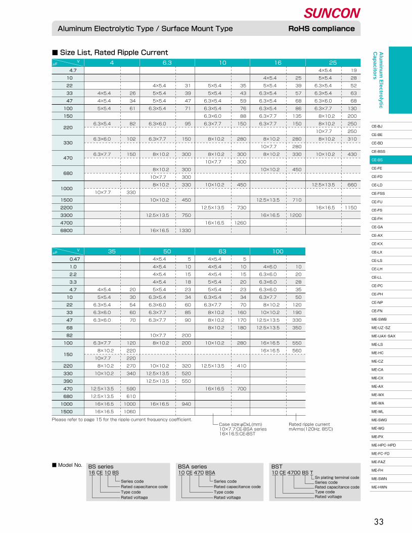
33
16 CE 10 BS
Series code�Rated capacitance code�Type code�Rated voltage
10 CE 470 BSA
Series code�Rated capacitance code�Type code�Rated voltage
10 CE 4700 BS TBS series BSA series BST
Sn plating terminal code�Series code�Rated capacitance code�Type code�Rated voltage
4×5.4 �
5×5.4 �
6.3×5.4 �
6.3×5.4 �
6.3×6.0 �
6.3×7.7 �
8×10.2�
8×10.2�
10×7.7 �
8×10.2�
�
10×10.2�
�
�
�
12.5×13.5�
�
�
16×16.5
19�
28�
52�
63�
68�
130�
200�
250�
250�
310�
�
430�
�
�
�
660�
�
�
1150
�
4×5.4 �
5×5.4 �
6.3×5.4 �
6.3×5.4 �
6.3×5.4 �
6.3×7.7 �
6.3×7.7 �
�
8×10.2�
10×7.7 �
8×10.2�
�
10×10.2�
�
�
�
12.5×13.5�
�
16×16.5
�
25�
39�
57�
68�
86�
135�
150�
�
280�
280�
330�
�
450�
�
�
�
710�
�
1200
�
�
5×5.4 �
5×5.4 �
6.3×5.4 �
6.3×5.4 �
6.3×6.0 �
6.3×7.7 �
�
8×10.2�
�
8×10.2�
10×7.7 �
�
�
10×10.2�
�
�
12.5×13.5�
�
16×16.5
�
�
35�
43�
59�
76�
88�
150�
�
280�
�
300�
300�
�
�
450�
�
�
730�
�
1260
�
�
4×5.4 �
5×5.4 �
5×5.4 �
6.3×5.4 �
�
6.3×6.0 �
�
6.3×7.7 �
�
8×10.2�
�
8×10.2�
10×7.7 �
8×10.2�
�
10×10.2�
�
12.5×13.5�
�
16×16.5
�
�
31�
39�
47�
71�
�
95�
�
150�
�
300�
�
300�
300�
330�
�
450�
�
750�
�
1330
�
�
�
4×5.4 �
4×5.4 �
5×5.4 �
�
6.3×5.4 �
�
6.3×6.0 �
�
6.3×7.7 �
�
�
�
�
10×7.7 �
�
�
�
26�
34�
61�
�
82�
�
102�
�
150�
�
�
�
�
330
■ Size List, Rated Ripple Current
■ Model No.
Aluminum Electrolytic Type / Surface Mount Type RoHS compliance
μFV 4 6.3 10 16 25
�
4×6.0 �
6.3×6.0 �
6.3×6.0 �
6.3×6.0 �
6.3×7.7 �
8×10.2�
10×10.2�
12.5×13.5�
12.5×13.5�
�
16×16.5�
16×16.5
�
10�
20�
28�
35�
50�
120�
190�
330�
350�
�
550�
560
4×5.4 �
4×5.4 �
4×5.4 �
5×5.4 �
5×5.4 �
6.3×5.4 �
6.3×7.7 �
8×10.2�
8×10.2�
8×10.2�
�
10×10.2�
�
�
12.5×13.5�
�
�
16×16.5
5�
10�
15�
20�
23�
34�
70�
160�
170�
180�
�
280�
�
�
410�
�
�
700
4×5.4 �
4×5.4 �
4×5.4 �
4×5.4 �
5×5.4 �
6.3×5.4 �
6.3×6.0 �
6.3×7.7 �
6.3×7.7 �
�
10×7.7 �
8×10.2�
�
�
10×10.2�
12.5×13.5�
12.5×13.5�
�
�
16×16.5
5�
10�
15�
18�
23�
34�
60�
85�
90�
�
200�
200�
�
�
320�
520�
550�
�
�
940
�
�
�
�
4×5.4 �
5×5.4 �
6.3×5.4 �
6.3×6.0 �
6.3×6.0 �
�
�
6.3×7.7 �
8×10.2�
10×7.7 �
8×10.2�
10×10.2�
�
12.5×13.5�
12.5×13.5�
16×16.5�
16×16.5
�
�
�
�
20�
30�
54�
60�
70�
�
�
120�
220�
220�
270�
340�
�
590�
610�
1000�
1060
μFV 35 50 63 100
4.7�
10 �
22 �
33 �
47 �
100 �
150 �
220 �
�
330 �
�
470 �
�
680 �
�
1000 � �
1500 �
2200 �
3300 �
4700 �
6800 �
�
0.47�
1.0�
2.2�
3.3�
4.7�
10 �
22 �
33 �
47 �
68 �
82 �
100 �
150 ��
220 �
330 �
390 �
470 �
680 �
1000 �
1500 �
Please refer to page 15 for the ripple current frequency coefficient.Rated ripple current�mArms(120Hz, 85℃)
Case size:φDxL(mm)�10×7.7:CE-BSA series�16×16.5:CE-BST
Alu
min
um
Electro
lytic C
apacito
rs
CE-BJ�
CE-BE�
CE-BD�
CE-BSS�
CE-BS�
CE-FE�
CE-FD�
CE-LD�
CE-FSS�
CE-FU�
CE-FS�
CE-FH�
CE-GA�
CE-AX�
CE-KX�
CE-LX�
CE-LS�
CE-LH�
CE-LL�
CE-PC�
CE-PH�
CE-NP�
CE-FN�
ME-SWB�
ME-UZ・SZ�
ME-UAX・SAX�
ME-LS�
ME-HC�
ME-CZ�
ME-CA�
ME-CX�
ME-AX�
ME-WX�
ME-WA�
ME-WL�
ME-SWG�
ME-WG�
ME-PX�
ME-HPC・HPD�
ME-FC・FD�
ME-FAZ�
ME-FH�
ME-SWN�
ME-HWN

34
●105℃, 1,000hrs.� ●Solvent proof (within 2 minutes)
CE-FE Series
Miniature Low Profile
3.9mm Height
■ Specifications
■ Marking, Dimensions
16 CE 22 FE
Series code�Rated capacitance code�Type code�Rated voltage
16 CE 22 FESFE series FES series
Series code�Rated capacitance code�Type code�Rated voltage
■ Model No.
■ Size List, Rated Ripple Current
D+0.5max W±0.2� H±0.2� C±0.2� R P±0.2�L +0.1�-0.2�
(Unit : mm)
5 �
6.3
3.9�
3.9
5.3�
6.6
5.3�
6.6
6.0�
7.3
0.5 to 0.8�
0.5 to 0.8
1.4�
2.2
Aluminum Electrolytic Type / Surface Mount Type RoHS compliance
Endurance
105℃, 1,000hrs.�rated voltage applied(With the rated�ripple current)
△C/C�
tanδ�
LC
�
-40 to +105�
M : ±20�
�
The greater value of either 0.01CV or 3�
�
�
6.3�
8.0�
�
�
0.38�
�
4�
10
10�
13�
�
�
0.32�
�
3�
8
16�
20�
�
�
0.20�
�
2�
6
25�
32�
�
�
0.16�
�
2�
4
35�
44�
�
�
0.14�
�
2�
4
50�
63�
�
�
0.14�
�
2�
4
SpecificationsConditionItems
Rated voltage�
Surge voltage�
Category temperature range�
Capacitance tolerance�
Dissipation Factor(tanδ)�
Leakage current(LC)�
(V)�
(V)�
(℃)�
(%)
-�
Room temperature�
-�
120Hz/20℃�
120Hz/20℃�
μA/after 2minutes (max)
Within ±30% of the initial value�
≤ 3 times the initial specified value�
≤ The initial specified value
Based the value at�120Hz, +20℃�
Impedance ratio at�low temperature
ー25℃�
ー40℃�
Z/Z20℃�
Z/Z20℃�
1422
F16 φD��
Polarity�(Cathode)
Lot No.
Rated Capacitance
Series Symbol
Rated Voltage(6.3V→6)
0.3max
L
W
(+)R
H� � P C
1.0�
2.2�
3.3�
4.7�
10 �
22 ��
33 ��
47 ��
68 �
100 �
μFV 6.3 10 16 25 35 50
5×3.9�
5×3.9�
5×3.9�
5×3.9�
6.3×3.9
�
�
�
5×3.9�
5×3.9�
�
6.3×3.9
�
�
�
13�
22�
�
34
�
�
�
5×3.9�
5×3.9�
�
6.3×3.9�
�
6.3×3.9
�
�
�
13�
21�
�
35�
�
42
�
�
�
�
5×3.9 �
5×3.9★�
6.3×3.9 �
�
6.3×3.9 �
�
6.3×3.9 �
�
�
�
�
18�
26�
31�
�
35�
�
42
�
�
�
�
�
�
5×3.9 �
5×3.9★�
6.3×3.9 �
�
6.3×3.9 �
�
�
�
�
�
�
25�
30�
35�
�
38
�
�
�
�
�
�
5×3.9 �
�
5×3.9 �
5×3.9★�
6.3×3.9 �
6.3×3.9 �
6.3×3.9 �
�
�
�
�
�
�
23�
�
28�
34�
42�
49�
52
6�
10�
12�
16�
23
Please refer to page 15 for the ripple current frequency coefficient.�★FES series Rated ripple current�
mArms(120Hz, 105℃)Case size:φDxL(mm)
Alu
min
um
Electro
lytic C
apacito
rs
CE-BJ�
CE-BE�
CE-BD�
CE-BSS�
CE-BS�
CE-FE�
CE-FD�
CE-LD�
CE-FSS�
CE-FU�
CE-FS�
CE-FH�
CE-GA�
CE-AX�
CE-KX�
CE-LX�
CE-LS�
CE-LH�
CE-LL�
CE-PC�
CE-PH�
CE-NP�
CE-FN�
ME-SWB�
ME-UZ・SZ�
ME-UAX・SAX�
ME-LS�
ME-HC�
ME-CZ�
ME-CA�
ME-CX�
ME-AX�
ME-WX�
ME-WA�
ME-WL�
ME-SWG�
ME-WG�
ME-PX�
ME-HPC・HPD�
ME-FC・FD�
ME-FAZ�
ME-FH�
ME-SWN�
ME-HWN
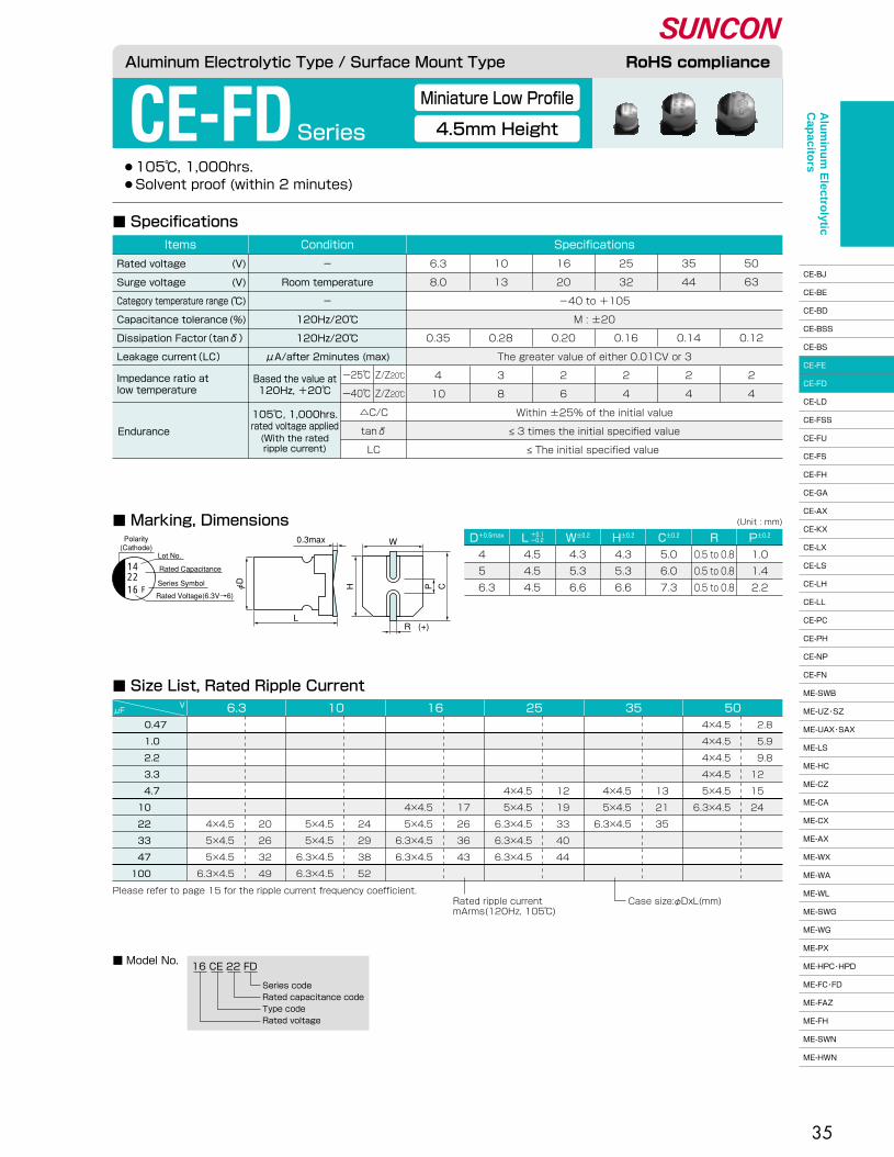
35
●105℃, 1,000hrs.� ●Solvent proof (within 2 minutes)
CE-FDSeries
■ Marking, Dimensions
■ Specifications
16 CE 22 FD
Series code�Rated capacitance code�Type code�Rated voltage
■ Model No.
D+0.5max W±0.2� H±0.2� C±0.2� R P±0.2�L +0.1�-0.2�
(Unit : mm)
4 �
5 �
6.3
4.5�
4.5�
4.5
4.3�
5.3�
6.6
4.3�
5.3�
6.6
5.0�
6.0�
7.3
0.5 to 0.8�
0.5 to 0.8�
0.5 to 0.8
1.0�
1.4�
2.2
0.47�
1.0 �
2.2 �
3.3 �
4.7 �
10 �
22 �
33 �
47 �
100 �
μFV 6.3 10 16 25 35 50
4×4.5�
4×4.5�
4×4.5�
4×4.5�
5×4.5�
6.3×4.5
�
�
�
�
4×4.5�
5×4.5�
6.3×4.5
�
�
�
�
13�
21�
35
�
�
�
�
4×4.5�
5×4.5�
6.3×4.5�
6.3×4.5�
6.3×4.5
�
�
�
�
12�
19�
33�
40�
44
�
�
�
�
�
4×4.5�
5×4.5�
6.3×4.5�
6.3×4.5
�
�
�
�
�
17�
26�
36�
43
�
�
�
�
�
�
5×4.5�
5×4.5�
6.3×4.5�
6.3×4.5
�
�
�
�
�
�
24�
29�
38�
52
�
�
�
�
�
�
4×4.5�
5×4.5�
5×4.5�
6.3×4.5
�
�
�
�
�
�
20�
26�
32�
49
2.8�
5.9�
9.8�
12 �
15 �
24 �
Please refer to page 15 for the ripple current frequency coefficient.Rated ripple current�mArms(120Hz, 105℃)
Case size:φDxL(mm)
■ Size List, Rated Ripple Current
Aluminum Electrolytic Type / Surface Mount Type RoHS compliance
Miniature Low Profile
4.5mm Height
Endurance
105℃, 1,000hrs.�rated voltage applied(With the rated�ripple current)
△C/C�
tanδ�
LC
�
-40 to +105�
M : ±20�
�
The greater value of either 0.01CV or 3�
�
�
6.3�
8.0�
�
�
0.35�
�
4�
10
10�
13�
�
�
0.28�
�
3�
8
16�
20�
�
�
0.20�
�
2�
6
25�
32�
�
�
0.16�
�
2�
4
35�
44�
�
�
0.14�
�
2�
4
50�
63�
�
�
0.12�
�
2�
4
SpecificationsConditionItems
Rated voltage�
Surge voltage�
Category temperature range�
Capacitance tolerance�
Dissipation Factor(tanδ)�
Leakage current(LC)�
(V)�
(V)�
(℃)�
(%)
-�
Room temperature�
-�
120Hz/20℃�
120Hz/20℃�
μA/after 2minutes (max)
Within ±25% of the initial value�
≤ 3 times the initial specified value�
≤ The initial specified value
Based the value at�120Hz, +20℃�
Impedance ratio at�low temperature
ー25℃�
ー40℃�
Z/Z20℃�
Z/Z20℃�
1422
F16 φD��
Polarity�(Cathode)
Lot No.
Rated Capacitance
Series Symbol
Rated Voltage(6.3V→6)
0.3max
L
W
(+)R
H� � P C
Alu
min
um
Electro
lytic C
apacito
rs
CE-BJ�
CE-BE�
CE-BD�
CE-BSS�
CE-BS�
CE-FE�
CE-FD�
CE-LD�
CE-FSS�
CE-FU�
CE-FS�
CE-FH�
CE-GA�
CE-AX�
CE-KX�
CE-LX�
CE-LS�
CE-LH�
CE-LL�
CE-PC�
CE-PH�
CE-NP�
CE-FN�
ME-SWB�
ME-UZ・SZ�
ME-UAX・SAX�
ME-LS�
ME-HC�
ME-CZ�
ME-CA�
ME-CX�
ME-AX�
ME-WX�
ME-WA�
ME-WL�
ME-SWG�
ME-WG�
ME-PX�
ME-HPC・HPD�
ME-FC・FD�
ME-FAZ�
ME-FH�
ME-SWN�
ME-HWN
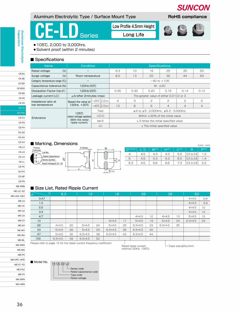
36
●105℃, 2,000 to 3,000hrs.� ●Solvent proof (within 2 minutes)
CE-LDSeries
Low Profile 4.5mm Height
Long Life
■ Specifications
■ Marking, DimensionsD+0.5max W±0.2� H±0.2� C±0.2� R P±0.2�L +0.1�-0.2�
(Unit : mm)
4 �
5 �
6.3
4.5�
4.5�
4.5
4.3�
5.3�
6.6
4.3�
5.3�
6.6
5.0�
6.0�
7.3
0.5 to 0.8�
0.5 to 0.8�
0.5 to 0.8
1.0�
1.4�
2.2
16 CE 22 LD
Series code�Rated capacitance code�Type code�Rated voltage
■ Model No.
0.47�
1.0 �
2.2 �
3.3 �
4.7 �
10 �
22 �
33 �
47 �
100 �
μFV 6.3 10 16 25 35 50
Please refer to page 15 for the ripple current frequency coefficient.Rated ripple current�mArms(120Hz, 105℃)
Case size:φDxL(mm)
■ Size List, Rated Ripple Current
4×4.5�
4×4.5�
4×4.5�
4×4.5�
5×4.5�
6.3×4.5
�
�
�
�
4×4.5�
5×4.5�
6.3×4.5
�
�
�
�
13�
24�
35
�
�
�
�
4×4.5�
5×4.5�
6.3×4.5�
6.3×4.5�
6.3×4.5
�
�
�
�
12�
19�
33�
40�
44
�
�
�
�
�
4×4.5�
5×4.5�
6.3×4.5�
6.3×4.5
�
�
�
�
�
17�
26�
36�
43
�
�
�
�
�
�
5×4.5�
5×4.5�
6.3×4.5�
6.3×4.5
�
�
�
�
�
�
24�
29�
38�
52
�
�
�
�
�
�
4×4.5�
5×4.5�
5×4.5�
6.3×4.5
�
�
�
�
�
�
20�
26�
32�
49
2.8�
5.9�
10 �
12 �
15 �
24 �
Aluminum Electrolytic Type / Surface Mount Type RoHS compliance
Endurance
105℃�rated voltage applied(With the rated�ripple current)
Test�
△C/C�
tanδ�
LC
ー25℃�
ー40℃�
Z/Z20℃�
Z/Z20℃�
�
-40 to +105�
M : ±20�
�
The greater value of either 0.01CV or 3�
�
�
6.3�
8.0�
�
�
0.35�
�
4�
10
10�
13�
�
�
0.30�
�
3�
8
16�
20�
�
�
0.20�
�
2�
6
25�
32�
�
�
0.16�
�
2�
4
35�
44�
�
�
0.14�
�
2�
4
50�
63�
�
�
0.12�
�
2�
4
SpecificationsConditionItems
Rated voltage�
Surge voltage�
Category temperature range�
Capacitance tolerance�
Dissipation Factor(tanδ)�
Leakage current(LC)�
(V)�
(V)�
(℃)�
(%)
-�
Room temperature�
-�
120Hz/20℃�
120Hz/20℃�
μA/after 2minutes (max)
φ4 to φ5 : 2,000hrs., φ6.3 : 3,000hrs.�
Within ±30% of the initial value�
≤ 3 times the initial specified value�
≤ The initial specified value
Based the value at�120Hz, +20℃�
Impedance ratio at�low temperature
Polarity�(Cathode)
Lot No.
Rated Capacitance
Series Symbol
Rated Voltage(6.3V→6)
0.3max
L
W
(+)R
H� � P C
1422
L16 φD��
Alu
min
um
Electro
lytic C
apacito
rs
CE-BJ�
CE-BE�
CE-BD�
CE-BSS�
CE-BS�
CE-FE�
CE-FD�
CE-LD�
CE-FSS�
CE-FU�
CE-FS�
CE-FH�
CE-GA�
CE-AX�
CE-KX�
CE-LX�
CE-LS�
CE-LH�
CE-LL�
CE-PC�
CE-PH�
CE-NP�
CE-FN�
ME-SWB�
ME-UZ・SZ�
ME-UAX・SAX�
ME-LS�
ME-HC�
ME-CZ�
ME-CA�
ME-CX�
ME-AX�
ME-WX�
ME-WA�
ME-WL�
ME-SWG�
ME-WG�
ME-PX�
ME-HPC・HPD�
ME-FC・FD�
ME-FAZ�
ME-FH�
ME-SWN�
ME-HWN
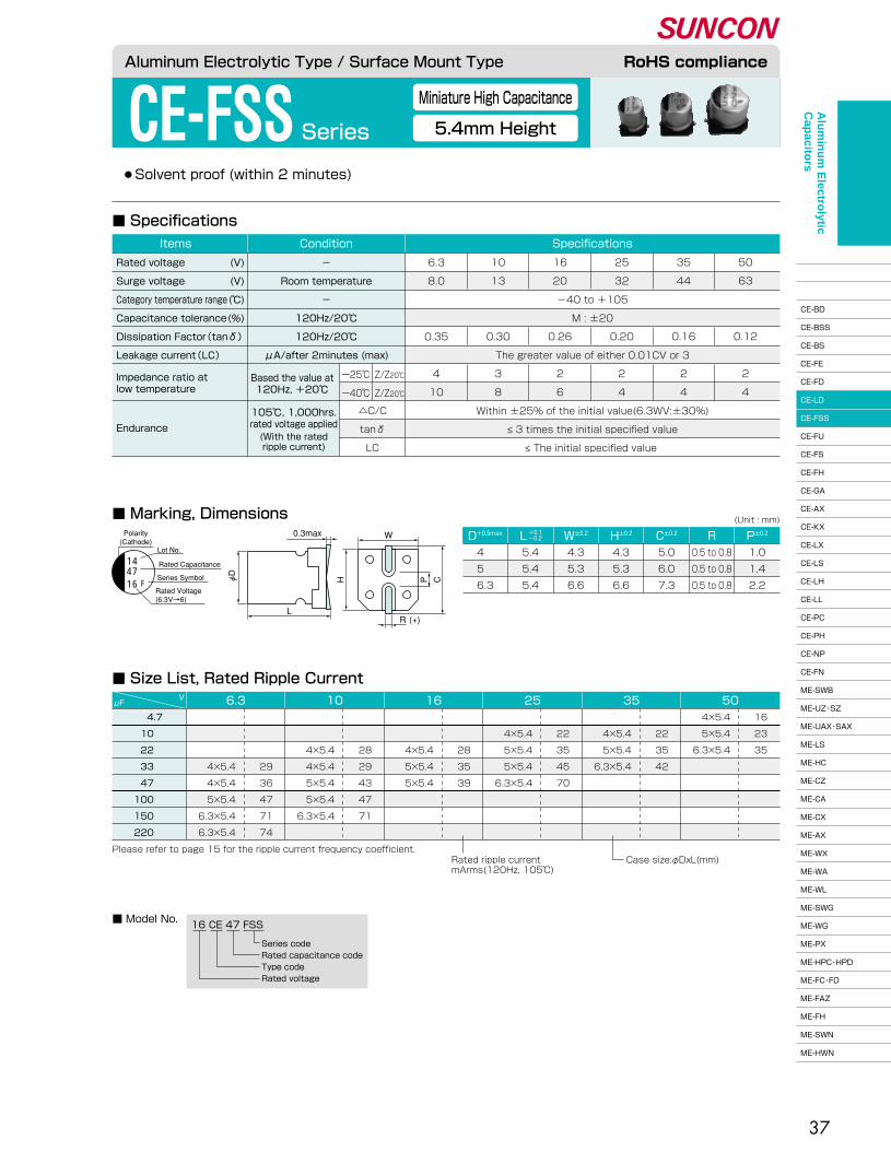
37
●Solvent proof (within 2 minutes)
CE-FSS Series
■ Marking, Dimensions
■ Specifications
16 CE 47 FSS
Series code�Rated capacitance code�Type code�Rated voltage
■ Model No.
D+0.5max W±0.2� H±0.2� C±0.2� R P±0.2�L +0.1�-0.2�
(Unit : mm)
4 �
5 �
6.3
5.4�
5.4�
5.4
4.3�
5.3�
6.6
4.3�
5.3�
6.6
5.0�
6.0�
7.3
0.5 to 0.8�
0.5 to 0.8�
0.5 to 0.8
1.0�
1.4�
2.2
4.7�
10 �
22 �
33 �
47 �
100 �
150 �
220 �
μFV 6.3 10 16 25 35 50
4×5.4�
5×5.4�
6.3×5.4
16�
23�
35
�
22�
35�
42
�
22�
35�
45�
70
�
�
28�
35�
39
�
�
28�
29�
43�
47�
71
�
�
�
29�
36�
47�
71�
74
�
4×5.4�
5×5.4�
6.3×5.4
�
4×5.4�
5×5.4�
5×5.4�
6.3×5.4
�
�
4×5.4�
5×5.4�
5×5.4
�
�
4×5.4�
4×5.4�
5×5.4�
5×5.4�
6.3×5.4
�
�
�
4×5.4�
4×5.4�
5×5.4�
6.3×5.4�
6.3×5.4
Please refer to page 15 for the ripple current frequency coefficient.Rated ripple current�mArms(120Hz, 105℃)
Case size:φDxL(mm)
■ Size List, Rated Ripple Current
Aluminum Electrolytic Type / Surface Mount Type RoHS compliance
Miniature High Capacitance
5.4mm Height
Polarity�(Cathode)
Lot No.
Rated Capacitance
Series Symbol
Rated Voltage�(6.3V→6)
0.3max
L
W
(+)R
H� � P C
1447
F16 φD��
Endurance
105℃, 1,000hrs.�rated voltage applied(With the rated�ripple current)
△C/C�
tanδ�
LC
�
�
-40 to +105�
M : ±20�
�
The greater value of either 0.01CV or 3�
�
�
�
6.3�
8.0�
�
�
0.35�
�
4�
10
10�
13�
�
�
0.30�
�
3�
8
16�
20�
�
�
0.26�
�
2�
6
25�
32�
�
�
0.20�
�
2�
4
35�
44�
�
�
0.16�
�
2�
4
50�
63�
�
�
0.12�
�
2�
4
SpecificationsConditionItems
Rated voltage�
Surge voltage�
Category temperature range�
Capacitance tolerance�
Dissipation Factor(tanδ)�
Leakage current(LC)�
(V)�
(V)�
(℃)�
(%)
-�
Room temperature�
-�
120Hz/20℃�
120Hz/20℃�
μA/after 2minutes (max)
Within ±25% of the initial value(6.3WV:±30%)�
≤ 3 times the initial specified value�
≤ The initial specified value
ー25℃�
ー40℃�
Z/Z20℃�
Z/Z20℃�
Based the value at�120Hz, +20℃�
Impedance ratio at�low temperature
Alu
min
um
Electro
lytic C
apacito
rs
CE-BJ�
CE-BE�
CE-BD�
CE-BSS�
CE-BS�
CE-FE�
CE-FD�
CE-LD�
CE-FSS�
CE-FU�
CE-FS�
CE-FH�
CE-GA�
CE-AX�
CE-KX�
CE-LX�
CE-LS�
CE-LH�
CE-LL�
CE-PC�
CE-PH�
CE-NP�
CE-FN�
ME-SWB�
ME-UZ・SZ�
ME-UAX・SAX�
ME-LS�
ME-HC�
ME-CZ�
ME-CA�
ME-CX�
ME-AX�
ME-WX�
ME-WA�
ME-WL�
ME-SWG�
ME-WG�
ME-PX�
ME-HPC・HPD�
ME-FC・FD�
ME-FAZ�
ME-FH�
ME-SWN�
ME-HWN

38
■ Marking, Dimensions
■ Specifications
■ Model No.
D+0.5max W±0.2� H±0.2� C±0.2� R P±0.2�(Unit : mm)
4 �
5 �
6.3
5.4�
5.4�
5.4
4.3�
5.3�
6.6
4.3�
5.3�
6.6
5.0�
6.0�
7.3
0.5 to 0.8�
0.5 to 0.8�
0.5 to 0.8
1.0�
1.4�
2.2
■ Size List, Rated Ripple Current
CE-FUSeries
Aluminum Electrolytic Type / Surface Mount Type RoHS compliance
High Temperature Reflow Soldering
5.4mm Height
Polarity�(Cathode)
Lot No.
Rated Capacitance
Series Symbol
Rated Voltage�(6.3V→6)
0.3max
L
W
(+)R
H� � P C
14100
U16 φD��
Endurance
105℃, 1,000hrs.�rated voltage applied(With the rated�ripple current)
△C/C�
tanδ�
LC
�
�
-55 to +105�
M : ±20�
�
The greater value of either 0.01CV or 3�
�
�
�
6.3�
8.0�
�
�
0.30�
�
4�
8
10�
13�
�
�
0.24�
�
3�
8
16�
20�
�
�
0.20�
�
2�
4
25�
32�
�
�
0.16�
�
2�
4
35�
44�
�
�
0.14�
�
2�
3
50�
63�
�
�
0.12�
�
2�
3
SpecificationsConditionItems
Rated voltage�
Surge voltage�
Category temperature range�
Capacitance tolerance�
Dissipation Factor(tanδ)�
Leakage current(LC)�
(V)�
(V)�
(℃)�
(%)
-�
Room temperature�
-�
120Hz/20℃�
120Hz/20℃�
μA/after 2minutes (max)
Within ±30% of the initial value�
≤ 3 times the initial specified value�
≤ The initial specified value
ー40℃�
ー55℃�
Z/Z20℃�
Z/Z20℃�
Based the value at�120Hz, +20℃�
Impedance ratio at�low temperature
● 105℃, 1,000hrs.� ●Solvent proof (within 2 minutes)
16 CE 100 FU
Series code�Rated capacitance code�Type code�Rated voltage
2.2�
3.3�
4.7�
10 �
22 �
33 �
47 �
100 �
μFV 6.3 10 16 25 35 50
4×5.4�
4×5.4�
5×5.4�
6.3×5.4
11�
13�
16�
24
�
�
14�
21�
38
�
�
13�
20�
36�
44
�
�
�
18�
27�
40�
48�
60
�
�
�
�
25�
30�
41�
53
�
�
�
�
22�
27�
33�
50
�
�
4×5.4�
5×5.4�
6.3×5.4
�
�
4×5.4�
5×5.4�
6.3×5.4�
6.3×5.4
�
�
�
4×5.4�
5×5.4�
6.3×5.4�
6.3×5.4�
6.3×5.4
�
�
�
�
5×5.4�
5×5.4�
6.3×5.4�
6.3×5.4
�
�
�
�
4×5.4�
5×5.4�
5×5.4�
6.3×5.4
Please refer to page 15 for the ripple current frequency coefficient.Rated ripple current�mArms(120Hz, 105℃)
Case size:φDxL(mm)
L +0.1�-0.2�
Alu
min
um
Electro
lytic C
apacito
rs
CE-BJ�
CE-BE�
CE-BD�
CE-BSS�
CE-BS�
CE-FE�
CE-FD�
CE-LD�
CE-FSS�
CE-FU�
CE-FS�
CE-FH�
CE-GA�
CE-AX�
CE-KX�
CE-LX�
CE-LS�
CE-LH�
CE-LL�
CE-PC�
CE-PH�
CE-NP�
CE-FN�
ME-SWB�
ME-UZ・SZ�
ME-UAX・SAX�
ME-LS�
ME-HC�
ME-CZ�
ME-CA�
ME-CX�
ME-AX�
ME-WX�
ME-WA�
ME-WL�
ME-SWG�
ME-WG�
ME-PX�
ME-HPC・HPD�
ME-FC・FD�
ME-FAZ�
ME-FH�
ME-SWN�
ME-HWN

39
●160 to 400V, 105℃, 1,000 to 2,000hrs.� ●Do not clean the capacitors using solvent.
CE-FSSeries
105℃ Standard
Mid.and High Voltage
■ Specifications
■ Marking, Dimensions
200 CE 10 FS
Series code�Rated capacitance code�Type code�Rated voltage
200 CE 47 FS TFS series FST■ Model No.
D+0.5max W±0.2� H±0.2� C±0.2� R P±0.2�L±0.3�(Unit : mm)
8 �
10 �
12.5�
16 �
8.3�
10.3�
12.8�
16.3
8.3�
10.3�
12.8�
16.3
9.0�
11.0�
13.5�
17.3
0.7 to 1.0�
1.0 to 1.4�
1.0 to 1.4�
1.8 to 2.1
3.2�
4.6�
4.6�
7.0
2.2�
3.3�
4.7�
6.8�
10 �
22 �
33 �
47 �
68 �
82 �
μFV 160 200 250 400
8×10.5�
10×10.5�
10×10.5�
12.5×13.5�
12.5×13.5�
16×16.5
25�
36�
38�
47�
57�
115
�
8×10.5�
8×10.5�
8×10.5�
10×10.5�
12.5×13.5�
16×16.5�
16×16.5
�
31�
37�
44�
64�
112�
150�
180
�
�
�
�
10×10.5�
12.5×13.5�
12.5×13.5�
16×16.5�
16×16.5
�
�
�
�
64�
112�
137�
180�
215
�
�
�
�
8×10.5�
12.5×13.5�
12.5×13.5�
16×16.5�
16×16.5�
16×16.5
�
�
�
�
57�
112�
137�
180�
215�
235
Please refer to page 15 for the ripple current frequency coefficient.Rated ripple current�mArms(120Hz, 105℃)
Case size:φDxL(mm)�16×16.5:CE-FST
■ Size List, Rated Ripple Current
10.5 �
10.5 �
13.5±0.5�
16.5±0.5�
Aluminum Electrolytic Type / Surface Mount Type RoHS compliance
CV ≤ 1,000�
CV > 1,000
Endurance
105℃�rated voltage applied(With the rated�ripple current)
Test�
△C/C�
tanδ�
LC
�
-40 to +105�
M : ±20�
�
0.03CV +15�
0.02CV +25�
�
160�
200�
�
�
�
�
�
3�
6
200�
250�
�
�
0.20�
�
�
3�
6
250�
300�
�
�
�
�
�
3�
6
400�
450�
�
�
0.25�
�
�
6�
10
SpecificationsConditionItems
Rated voltage�
Surge voltage�
Category temperature range�
Capacitance tolerance�
Dissipation Factor(tanδ)�
Leakage current(LC)�
(V)�
(V)�
(℃)�
(%)
-�
Room temperature�
-�
120Hz/20℃�
120Hz/20℃�
φ8 : 1,000hrs., φ10 to φ16 : 2,000hrs.�
Within ±25% of the initial value�
≤ 2 times the initial specified value�
≤ The initial specified value
Based the value at�120Hz, +20℃�
μA/after�2minutes (max)
Impedance ratio at�low temperature
ー25℃�
ー40℃�
Z/Z20℃�
Z/Z20℃�
10F200
14
47F200
Polarity�(Cathode)
[φD≤10]
[φD≥12.5]
Lot No.Rated Capacitance
Series Symbol
Rated Voltage
Polarity�(Cathode)
Lot No.
Indicated Only φD=16
Rated Capacitance
Series Symbol
Rated Voltage
14T
0.3max
L
W
(+)R
φD
H P C
pressure relief vent
Sn plating terminal code�Series code�Rated capacitance code�Type code�Rated voltage
Alu
min
um
Electro
lytic C
apacito
rs
CE-BJ�
CE-BE�
CE-BD�
CE-BSS�
CE-BS�
CE-FE�
CE-FD�
CE-LD�
CE-FSS�
CE-FU�
CE-FS�
CE-FH�
CE-GA�
CE-AX�
CE-KX�
CE-LX�
CE-LS�
CE-LH�
CE-LL�
CE-PC�
CE-PH�
CE-NP�
CE-FN�
ME-SWB�
ME-UZ・SZ�
ME-UAX・SAX�
ME-LS�
ME-HC�
ME-CZ�
ME-CA�
ME-CX�
ME-AX�
ME-WX�
ME-WA�
ME-WL�
ME-SWG�
ME-WG�
ME-PX�
ME-HPC・HPD�
ME-FC・FD�
ME-FAZ�
ME-FH�
ME-SWN�
ME-HWN

40
CE-FS Series
■ Marking, Dimensions
■ Specifications
105℃ Standard
●105℃, 1,000 to 2,000hrs.� ●Solvent proof (within 2 minutes)
(Unit : mm)
Aluminum Electrolytic Type / Surface Mount Type RoHS compliance
Endurance
120Hz/20℃�
Test�
△C/C�
tanδ�
LC
φ4 to φ6.3�
φ8 to φ18
�
�
�
�
�
When rated capacitance exceeds 1,000μF, add 0.02 to the value above for each 1,000μF increase.�
The greater value of either 0.01CV or 3�
�
�
6.3�
8.0�
�
�
0.24�
0.28�
�
�
3�
8
10�
13�
�
�
0.20�
0.24�
�
�
3�
5
16�
20�
�
�
0.16�
0.20�
�
�
2�
4
25�
32�
-55 to +105�
M : ±20�
0.14�
0.16�
�
�
2�
3
35�
44�
�
�
0.12�
0.14�
�
�
2�
3
50�
63�
�
�
0.10�
0.12�
�
�
2�
3
63�
79�
�
�
0.12�
0.12�
�
�
2�
3
100�
125�
-40 to +105�
�
0.10�
0.10�
�
�
3�
-�
SpecificationsConditionItems
Rated voltage�
Surge Voltage�
Category temperature range�
Capacitance tolerance�
�
Dissipation Factor(tanδ)�
�
Leakage current(LC)�
(V)�
(V)�
(℃)�
(%)
-�
Room temperature�
-�
120Hz/20℃�
�
�
�
μA/after 2minutes (max)
φ4 to φ6.3, φ10 × 7.7 : 1,000hrs., φ8 to φ18 : 2,000hrs.�
Within ±25% of the initial value�
≤ 2 times the initial specified value�
≤ The initial specified value
105℃�rated voltage applied(With the rated�ripple current)
Based the value at�120Hz, +20℃�
Impedance ratio at�low temperature
ー40℃�
ー55℃�
Z/Z20℃�
Z/Z20℃�
4700F10
14T
Polarity�(Cathode)
Lot No.
Rated Capacitance
Series Symbol
Rated Voltage(6.3V→6)
Polarity�(Cathode) Lot No.
indicated φD=16, 18
Rated Capacitance
Series Symbol
Rated Voltage(6.3V→6)
[φD≤10]
[φD≥12.5]
0.3max
L
W
(+)R
φD��
H� � P C
470F16
14
A pressure relief vent is attached to �products over φD=8
φ18×16.5
D+0.5max W±0.2� H±0.2� C±0.2� R P±0.2�L5.4 �
6.0±0.3�
5.4 �
5.4 �
6.0±0.3�
7.7±0.3�
10.2±0.3�
7.7±0.3�
10.2±0.3�
13.5±0.5�
16.5±0.5�
16.5±1.0�
4 �
4 �
5 �
6.3�
6.3�
6.3�
8 �
10 �
10 �
12.5�
16 �
18 �
4.3�
4.3�
5.3�
6.6�
6.6�
6.6�
8.3�
10.3�
10.3�
12.8�
16.3�
19.0
4.3�
4.3�
5.3�
6.6�
6.6�
6.6�
8.3�
10.3�
10.3�
12.8�
16.3�
19.0
5.0�
5.0�
6.0�
7.3�
7.3�
7.3�
9.0�
11.0�
11.0�
13.5�
17.3�
20.0
0.5 to 0.8�
0.5 to 0.8�
0.5 to 0.8�
0.5 to 0.8�
0.5 to 0.8�
0.5 to 0.8�
0.7 to 1.0�
1.0 to 1.4�
1.0 to 1.4�
1.0 to 1.4�
1.8 to 2.1�
1.7 to 2.1
1.0�
1.0�
1.4�
2.2�
2.2�
2.2�
3.2�
4.6�
4.6�
4.6�
7.0�
7.0
+0.1�-0.2�
+0.1�-0.2�
+0.1�-0.2�
Alu
min
um
Electro
lytic C
apacito
rs
CE-BJ�
CE-BE�
CE-BD�
CE-BSS�
CE-BS�
CE-FE�
CE-FD�
CE-LD�
CE-FSS�
CE-FU�
CE-FS�
CE-FH�
CE-GA�
CE-AX�
CE-KX�
CE-LX�
CE-LS�
CE-LH�
CE-LL�
CE-PC�
CE-PH�
CE-NP�
CE-FN�
ME-SWB�
ME-UZ・SZ�
ME-UAX・SAX�
ME-LS�
ME-HC�
ME-CZ�
ME-CA�
ME-CX�
ME-AX�
ME-WX�
ME-WA�
ME-WL�
ME-SWG�
ME-WG�
ME-PX�
ME-HPC・HPD�
ME-FC・FD�
ME-FAZ�
ME-FH�
ME-SWN�
ME-HWN

41
10 CE 470 FSA
Series code�Rated capacitance code�Type code�Rated voltage
16 CE 470 FS
Series code�Rated capacitance code�Type code�Rated voltage
10 CE 4700 FS TFSA seriesFS series FST
■ Size List, Rated Ripple Current
■ Model No.
Aluminum Electrolytic Type / Surface Mount Type RoHS compliance
4×5.4 �
5×5.4 �
6.3×5.4 �
6.3×5.4 �
6.3×6.0 �
6.3×7.7 �
8×10.2�
�
8×10.2�
10×7.7 �
8×10.2�
�
10×10.2�
�
�
�
12.5×13.5�
�
16×16.5�
18×16.5
13�
20�
36�
44�
48�
91�
140�
�
175�
175�
220�
�
300�
�
�
�
460�
�
805�
1040
�
4×5.4 �
5×5.4 �
6.3×5.4 �
6.3×5.4 �
6.3×5.4 �
6.3×7.7 �
�
6.3×7.7 �
�
8×10.2�
10×7.7 �
8×10.2�
�
10×10.2�
�
�
12.5×13.5�
�
16×16.5�
18×16.5
�
18�
27�
40�
48�
60�
95�
�
105�
�
195�
195�
230�
�
310�
�
�
500�
�
840�
1090
�
�
5×5.4 �
5×5.4 �
6.3×5.4 �
6.3×5.4 �
6.3×6.0 �
�
6.3×7.7 �
�
8×10.2�
�
8×10.2�
10×7.7 �
�
�
10×10.2�
�
12.5×13.5�
�
16×16.5�
18×16.5
�
�
25�
30�
41�
53�
62�
�
105�
�
195�
�
210�
210�
�
�
310�
�
510�
�
880�
1150
�
�
4×5.4 �
5×5.4 �
5×5.4 �
6.3×5.4 �
�
�
6.3×6.0 �
�
6.3×7.7 �
�
8×10.2�
�
8×10.2�
10×7.7 �
8×10.2�
10×10.2�
�
12.5×13.5�
�
16×16.5�
18×16.5
�
�
22�
27�
33�
50�
�
�
67�
�
105�
�
210�
�
210�
210�
230�
310�
�
520�
�
930�
1200
μFV 6.3 10 16 25
4×5.4 �
5×5.4 �
6.3×5.4 �
6.3×6.0 �
6.3×6.0 �
6.3×7.7 �
8×10.2�
10×7.7 �
8×10.2�
�
10×10.2�
�
12.5×13.5�
�
12.5×13.5�
�
16×16.5�
16×16.5�
18×16.5
14�
21�
38�
42�
49�
84�
155�
155�
190�
�
300�
�
410�
�
430�
�
700�
740�
950
354.7�
10 �
22 �
33 �
47 �
100 �
150 �
�
220 �
�
330 �
�
470 �
�
680 �
�1000 �
1500 �
2200 �
3300 �
4700 �
6800 �
10000 �
�
4×6.0 �
6.3×6.0 �
6.3×6.0 �
6.3×6.0 �
6.3×7.7 �
8×10.2�
10×10.2�
12.5×13.5�
12.5×13.5�
�
16×16.5�
16×16.5�
18×16.5
�
7.0�
14 �
20 �
25 �
35 �
84 �
133 �
240 �
245 �
�
490 �
500 �
650 �
4×5.4 �
4×5.4 �
4×5.4 �
5×5.4 �
5×5.4 �
6.3×5.4 �
6.3×7.7 �
8×10.2�
8×10.2�
8×10.2�
�
10×10.2�
�
12.5×13.5�
�
�
16×16.5�
18×16.5
3.5 �
7.0 �
11 �
14 �
16 �
24 �
49 �
112 �
119 �
126 �
�
196 �
�
287 �
�
�
630 �
750 �
4×5.4 �
4×5.4 �
4×5.4 �
4×5.4 �
5×5.4 �
6.3×5.4 �
6.3×6.0 �
6.3×7.7 �
6.3×7.7 �
�
10×7.7 �
8×10.2�
�
10×10.2�
12.5×13.5�
12.5×13.5�
�
�
16×16.5
3.5 �
7.0 �
11 �
13 �
16 �
24 �
42 �
60 �
63 �
�
140 �
140 �
�
220 �
365 �
380 �
�
�
655 �
μFV 50 63 100
0.47�
1.0 �
2.2 �
3.3 �
4.7 �
10 �
22 �
33 �
47 �
68 �
82 �
100 �
150 �
220 �
330 �
390 �
470 �
680 �
1000 �
Please refer to page 15 for the �ripple current frequency coefficient. Rated ripple current�
mArms(120Hz, 105℃)Case size:φDxL(mm)�10×7.7:CE-FSA serise�16×16.5, 18×16.5:CE-FST
Sn plating terminal code�Series code�Rated capacitance code�Type code�Rated voltage
Alu
min
um
Electro
lytic C
apacito
rs
CE-BJ�
CE-BE�
CE-BD�
CE-BSS�
CE-BS�
CE-FE�
CE-FD�
CE-LD�
CE-FSS�
CE-FU�
CE-FS�
CE-FH�
CE-GA�
CE-AX�
CE-KX�
CE-LX�
CE-LS�
CE-LH�
CE-LL�
CE-PC�
CE-PH�
CE-NP�
CE-FN�
ME-SWB�
ME-UZ・SZ�
ME-UAX・SAX�
ME-LS�
ME-HC�
ME-CZ�
ME-CA�
ME-CX�
ME-AX�
ME-WX�
ME-WA�
ME-WL�
ME-SWG�
ME-WG�
ME-PX�
ME-HPC・HPD�
ME-FC・FD�
ME-FAZ�
ME-FH�
ME-SWN�
ME-HWN

42
●105℃, 2,000 to 5,000hrs.� ●Solvent proof (within 2 minutes)
CE-FHSeriesLong Life
■ Specifications
D+0.5max W±0.2� H±0.2� C±0.2� R P±0.2�L±0.3�(Unit : mm)
4 �
5 �
6.3�
6.3�
8 �
10 �
12.5�
16 �
4.3�
5.3�
6.6�
6.6�
8.3�
10.3�
12.8�
16.3
4.3�
5.3�
6.6�
6.6�
8.3�
10.3�
12.8�
16.3
5.0�
6.0�
7.3�
7.3�
9.0�
11.0�
13.5�
17.3
1.0�
1.4�
2.2�
2.2�
3.2�
4.6�
4.6�
7.0
0.5 to 0.8�
0.5 to 0.8�
0.5 to 0.8�
0.5 to 0.8�
0.7 to 1.0�
1.0 to 1.4�
1.0 to 1.4�
1.8 to 2.1
■ Marking, Dimensions
16 CE 470 FH
Series code�Rated capacitance code�Type code�Rated voltage
■ Model No.
1.0 �
2.2 �
3.3 �
4.7 �
10 �
22 �
33 �
47 �
100 �
220 �
330 �
470 �
680 �
1000 �
1500 �
2200 �
3300 �
4700 �
4×6.0 �
4×6.0 �
4×6.0 �
5×6.0 �
6.3×6.0 �
6.3×7.7 �
8×10.2�
8×10.2�
10×10.2�
12.5×13.5�
�
16×16.5
7 �
11 �
13 �
19 �
32 �
60 �
140 �
150 �
220 �
340 �
�
610 �
�
�
�
4×6.0 �
5×6.0 �
6.3×6.0 �
6.3×7.7 �
8×10.2�
8×10.2�
10×10.2�
12.5×13.5�
�
�
16×16.5
�
�
�
15�
25�
44�
77�
150�
160�
290�
380�
�
�
620
�
�
�
4×6.0 �
5×6.0 �
6.3×6.0 �
6.3×6.0 �
6.3×7.7 �
8×10.2�
8×10.2�
10×10.2�
12.5×13.5�
12.5×13.5�
�
16×16.5
�
�
�
13�
23�
42�
58�
91�
150�
195�
290�
400�
415�
�
720
�
�
�
�
4×6.0 �
5×6.0 �
6.3×6.0 �
6.3×6.0 �
6.3×7.7 �
8×10.2�
8×10.2�
10×10.2�
�
12.5×13.5�
�
16×16.5
�
�
�
�
18�
30�
44�
60�
95�
175�
210�
290�
�
440�
�
785
�
�
�
�
�
5×6.0 �
5×6.0 �
6.3×6.0 �
6.3×6.0 �
8×10.2�
8×10.2�
8×10.2�
10×10.2�
�
12.5×13.5�
�
16×16.5
�
�
�
�
�
27�
35�
46�
62�
175�
195�
210�
300�
�
480�
�
820
�
�
�
�
�
4×6.0 �
5×6.0 �
5×6.0 �
6.3×6.0 �
6.3×7.7 �
8×10.2�
8×10.2�
�
10×10.2�
�
12.5×13.5�
�
16×16.5
�
�
�
�
�
22�
30�
36�
67�
105�
195�
210�
�
300�
�
490�
�
860
Please refer to page 15 for the ripple current frequency coefficient. Rated ripple current�mArms(120Hz, 105℃)
Case size:φDxL(mm)�16×16.5:CE-FHT
16 CE 2200 FH TFH series FHT
μFV 6.3 10 16 25 35 50
■ Size List, Rated Ripple Current
6.0 �
6.0 �
6.0 �
7.7 �
10.2 �
10.2 �
13.5±0.5�
16.5±0.5�
Aluminum Electrolytic Type / Surface Mount Type RoHS compliance
Endurance
105℃�rated voltage applied(With the rated�ripple current)
Test�
△C/C�
tanδ�
LC
�
-40 to +105�
M : ±20�
�
When rated capacitance exceeds 1,000μF, add 0.02 to the value above for each 1,000μF increase.�
The greater value of either 0.01CV or 3�
�
�
6.3�
8.0�
�
�
0.30�
�
�
4�
8
10�
13�
�
�
0.24�
�
�
3�
6
16�
20�
�
�
0.20�
�
�
2�
4
25�
32�
�
�
0.16�
�
�
2�
4
35�
44�
�
�
0.14�
�
�
2�
3
50�
63�
�
�
0.14�
�
�
2�
3
SpecificationsConditionItemsRated voltage�
Surge voltage�
Category temperature range�
Capacitance tolerance�
Dissipation Factor(tanδ)��
Leakage current(LC)�
(V)�
(V)�
(℃)�
(%)
-�
Room temperature�
-�
120Hz/20℃�
120Hz/20℃�
�
μA/after 2minutes (max)
φ4 to φ6.3 : 2,000hrs., φ8 to φ10 : 3,000hrs., φ12.5 to φ16 : 5,000hrs.�
Within ±25% of the initial value�
≤ 2.5 times the initial specified value�≤ The initial specified value
Based the value at�120Hz, +20℃�
Impedance ratio at�low temperature
ー25℃�
ー40℃�Z/Z20℃�
Z/Z20℃�
0.3max
L
W
(+)R
φD H� � P C
470H16
14
2200H16
Polarity�(Cathode)
[φD≤10]
[φD≥12.5]
Lot No.
Rated Capacitance
Series Symbol
Rated Voltage(6.3V→6)
Polarity�(Cathode) Lot No.
Indicated Only φD=16Rated Capacitance
Series Symbol
Rated Voltage(6.3V→6)
14T A pressure relief vent is attached to �products over φD=8
Sn plating terminal code�Series code�Rated capacitance code�Type code�Rated voltage
Alu
min
um
Electro
lytic C
apacito
rs
CE-BJ�
CE-BE�
CE-BD�
CE-BSS�
CE-BS�
CE-FE�
CE-FD�
CE-LD�
CE-FSS�
CE-FU�
CE-FS�
CE-FH�
CE-GA�
CE-AX�
CE-KX�
CE-LX�
CE-LS�
CE-LH�
CE-LL�
CE-PC�
CE-PH�
CE-NP�
CE-FN�
ME-SWB�
ME-UZ・SZ�
ME-UAX・SAX�
ME-LS�
ME-HC�
ME-CZ�
ME-CA�
ME-CX�
ME-AX�
ME-WX�
ME-WA�
ME-WL�
ME-SWG�
ME-WG�
ME-PX�
ME-HPC・HPD�
ME-FC・FD�
ME-FAZ�
ME-FH�
ME-SWN�
ME-HWN
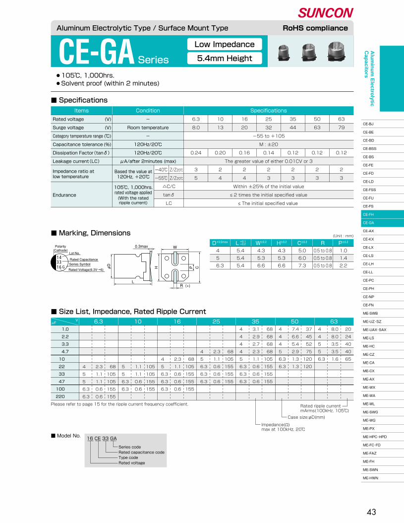
43
●105℃, 1,000hrs.� ●Solvent proof (within 2 minutes)
CE-GA Series
Low Impedance
5.4mm Height
■ Specifications
■ Marking, Dimensions
16 CE 33 GA
Series code�Rated capacitance code�Type code�Rated voltage
1.0 �
2.2 �
3.3 �
4.7 �
10 �
22 �
33 �
47 �
100 �
220 �
20�
24�
40�
40�
65
8.0�
8.0�
3.5�
3.5�
1.6
4 �
4 �
5 �
5 �
6.3
37�
45�
52�
75�
120�
120
7.4�
6.6�
5.4�
2.9�
1.3�
1.3
4 �
4 �
4 �
5 �
6.3�
6.3
68�
68�
68�
68�
105�
155�
155�
155
3.1�
2.9�
2.7�
2.3�
1.1�
0.6�
0.6�
0.6
4 �
4 �
4 �
4 �
5 �
6.3�
6.3�
6.3
�
�
�
68�
105�
155�
155�
155
�
�
�
2.3�
1.1�
0.6�
0.6�
0.6
�
�
�
4 �
5 �
6.3�
6.3�
6.3
�
�
�
�
68�
105�
155�
155�
155
�
�
�
�
2.3�
1.1�
0.6�
0.6�
0.6
�
�
�
�
4 �
5 �
6.3�
6.3�
6.3
�
�
�
�
�
105�
105�
155�
155
�
�
�
�
�
1.1�
1.1�
0.6�
0.6
�
�
�
�
�
5 �
5 �
6.3�
6.3
�
�
�
�
�
68�
105�
105�
155�
155
�
�
�
�
�
2.3�
1.1�
1.1�
0.6�
0.6
�
�
�
�
�
4 �
5 �
5 �
6.3�
6.3
6.3μFV 10 16 25 35 50 63
Please refer to page 15 for the ripple current frequency coefficient. Rated ripple current�mArms(100kHz, 105℃)
Case size:φD(mm)
Impedance(Ω)�max at 100kHz, 20℃�
■ Size List, Impedance, Rated Ripple Current
■ Model No.
D+0.5max W±0.2� H±0.2� C±0.2� R P±0.2�L +0.1�-0.2�
(Unit : mm)
4 �
5 �
6.3
5.4�
5.4�
5.4
4.3�
5.3�
6.6
4.3�
5.3�
6.6
5.0�
6.0�
7.3
0.5 to 0.8�
0.5 to 0.8�
0.5 to 0.8
1.0�
1.4�
2.2
Aluminum Electrolytic Type / Surface Mount Type RoHS compliance
Endurance
105℃, 1,000hrs.�rated voltage applied(With the rated�ripple current)
△C/C�
tanδ�
LC
25�
32�
-55 to +105�
M : ±20�
0.14�
The greater value of either 0.01CV or 3�
2�
3
6.3�
8.0�
�
�
0.24�
�
3�
5
10�
13�
�
�
0.20�
�
2�
4
16�
20�
�
�
0.16�
�
2�
4
35�
44�
�
�
0.12�
�
2�
3
50�
63�
�
�
0.12�
�
2�
3
63�
79�
�
�
0.12�
�
2�
3
SpecificationsConditionItems
Rated voltage�
Surge voltage�
Category temperature range�
Capacitance tolerance�
Dissipation Factor(tanδ)�
Leakage current(LC)�
(V)�
(V)�
(℃)�
(%)
-�
Room temperature�
-�
120Hz/20℃�
120Hz/20℃�
μA/after 2minutes (max)
Within ±25% of the initial value�
≤ 2 times the initial specified value�
≤ The initial specified value
Based the value at�120Hz, +20℃�
Impedance ratio at�low temperature
ー40℃�
ー55℃�
Z/Z20℃�
Z/Z20℃�
Polarity�(Cathode)
Lot No.
Rated CapacitanceSeries Symbol
Rated Voltage(6.3V→6)
0.3max
L
W
(+)R
φD��
H� � P C
1433
G16
Alu
min
um
Electro
lytic C
apacito
rs
CE-BJ�
CE-BE�
CE-BD�
CE-BSS�
CE-BS�
CE-FE�
CE-FD�
CE-LD�
CE-FSS�
CE-FU�
CE-FS�
CE-FH�
CE-GA�
CE-AX�
CE-KX�
CE-LX�
CE-LS�
CE-LH�
CE-LL�
CE-PC�
CE-PH�
CE-NP�
CE-FN�
ME-SWB�
ME-UZ・SZ�
ME-UAX・SAX�
ME-LS�
ME-HC�
ME-CZ�
ME-CA�
ME-CX�
ME-AX�
ME-WX�
ME-WA�
ME-WL�
ME-SWG�
ME-WG�
ME-PX�
ME-HPC・HPD�
ME-FC・FD�
ME-FAZ�
ME-FH�
ME-SWN�
ME-HWN

44
●105℃, 1,000 to 2,000hrs.� ●Solvent proof (within 2 minutes)
CE-AX Series
■ Specifications
■ Marking, Dimensions
Low Impedance
D+0.5max W±0.2� H±0.2� C±0.2� R P±0.2�L±0.3�(Unit : mm)
4 �
5 �
6.3�
6.3�
8 �
10 �
10 �
12.5�
16 �
4.3�
5.3�
6.6�
6.6�
8.3�
10.3�
10.3�
12.8�
16.3
4.3�
5.3�
6.6�
6.6�
8.3�
10.3�
10.3�
12.8�
16.3
5.0�
6.0�
7.3�
7.3�
9.0�
11.0�
11.0�
13.5�
17.3
1.0�
1.4�
2.2�
2.2�
3.2�
4.6�
4.6�
4.6�
7.0
0.5 to 0.8�
0.5 to 0.8�
0.5 to 0.8�
0.5 to 0.8�
0.7 to 1.0�
1.0 to 1.4�
1.0 to 1.4�
1.0 to 1.4�
1.8 to 2.1
6.0 �
6.0 �
6.0 �
7.7 �
10.2 �
7.7 �
10.2 �
13.5±0.5�
16.5±0.5�
Aluminum Electrolytic Type / Surface Mount Type RoHS compliance
Endurance
120Hz/20℃�
Test�
△C/C�
tanδ�
LC
φ4 to φ6.3�
φ8 to φ16
�
-55 to +105�
M : ±20�
�
�
When rated capacitance exceeds 1,000μF, add 0.02 to the value above for each 1,000μF increase.�
The greater value of either 0.01CV or 3�
�
�
6.3�
8.0�
�
�
0.24�
0.28�
�
�
3�
5
10�
13�
�
�
0.20�
0.24�
�
�
2�
4
16�
20�
�
�
0.16�
0.20�
�
�
2�
4
25�
32�
�
�
0.14�
0.16�
�
�
2�
3
35�
44�
�
�
0.12�
0.14�
�
�
2�
3
50�
63�
�
�
0.12�
0.14�
�
�
2�
3
SpecificationsConditionItems
Rated voltage�
Surge voltage�
Category temperature range�
Capacitance tolerance�
�
Dissipation Factor(tanδ)�
�
Leakage current(LC)�
(V)�
(V)�
(℃)�
(%)
-�
Room temperature�
-�
120Hz/20℃�
�
�
�
μA/after 2minutes (max)
φ4 to φ6.3,φ10×7.7 : 1,000hrs., φ8 to φ16 : 2,000hrs.�
Within ±25% of the initial value�
≤ 2 times the initial specified value�
≤ The initial specified value
105℃�rated voltage applied(With the rated�ripple current)
Based the value at�120Hz, +20℃�
Impedance ratio at�low temperature
ー40℃�
ー55℃�
Z/Z20℃�
Z/Z20℃�
0.3max
L
W
(+)R
φD��
H� � P C
470A16
14
4700A10
Polarity�(Cathode)
[φD≤10]
[φD≥12.5]
Lot No.Rated Capacitance
Series SymbolRated Voltage(6.3V→6)
Polarity�(Cathode) Lot No.
Indicated Only φD=16
Rated CapacitanceSeries Symbol
Rated Voltage(6.3V→6)
14T A pressure relief vent is attached to �products over φD=8
Alu
min
um
Electro
lytic C
apacito
rs
CE-BJ�
CE-BE�
CE-BD�
CE-BSS�
CE-BS�
CE-FE�
CE-FD�
CE-LD�
CE-FSS�
CE-FU�
CE-FS�
CE-FH�
CE-GA�
CE-AX�
CE-KX�
CE-LX�
CE-LS�
CE-LH�
CE-LL�
CE-PC�
CE-PH�
CE-NP�
CE-FN�
ME-SWB�
ME-UZ・SZ�
ME-UAX・SAX�
ME-LS�
ME-HC�
ME-CZ�
ME-CA�
ME-CX�
ME-AX�
ME-WX�
ME-WA�
ME-WL�
ME-SWG�
ME-WG�
ME-PX�
ME-HPC・HPD�
ME-FC・FD�
ME-FAZ�
ME-FH�
ME-SWN�
ME-HWN

4.7�
10 �
15 �
22 �
27 �
33 �
47 �
56 �
68 �
100 �
150 �
�
220 �
�
330 ��
390 �
470 �
�
680 �
�1000 �
1500 �
2200 �
3300 �
4700 �
6800 �
μFV 6.3 10 16 25 35 50
4×6.0 �
5×6.0 �
5×6.0 �
5×6.0 �
�
6.3×6.0 �
6.3×6.0 �
�
6.3×7.7 �
8×10.2�
8×10.2�
10×7.7 �
8×10.2�
�
10×10.2�
�
�
12.5×13.5�
�
12.5×13.5�
�
�
16×16.5
80�
150�
150�
150�
�
230�
230�
�
280�
450�
450�
450�
450�
�
670�
�
�
900�
�
900�
�
�
1250
1.80 �
0.76 �
0.76 �
0.76 �
�
0.44 �
0.44 �
�
0.34 �
0.17 �
0.17 �
0.17 �
0.17 �
�
0.090�
�
�
0.066�
�
0.066�
�
�
0.052
�
4×6.0 �
5×6.0 �
5×6.0 �
�
6.3×6.0 �
6.3×6.0 �
6.3×6.0 �
6.3×6.0 �
6.3×7.7 �
8×10.2�
�
8×10.2�
10×7.7 �
8×10.2�
�
�
10×10.2�
�
�
�
12.5×13.5�
�
16×16.5
�
80�
150�
150�
�
230�
230�
230�
230�
280�
450�
�
450�
450�
450�
�
�
670�
�
�
�
900�
�
1250
�
1.80 �
0.76 �
0.76 �
�
0.44 �
0.44 �
0.44 �
0.44 �
0.34 �
0.17 �
�
0.17 �
0.17 �
0.17 �
�
�
0.090�
�
�
�
0.066�
�
0.052
�
�
4×6.0 �
5×6.0 �
�
�
6.3×6.0 �
�
6.3×6.0 �
6.3×6.0 �
6.3×7.7 �
�
6.3×7.7 �
�
8×10.2�
10×7.7 �
�
8×10.2�
�
10×10.2�
�
�
12.5×13.5�
�
16×16.5
�
�
80�
150�
�
�
230�
�
230�
230�
280�
�
280�
�
450�
450�
�
450�
�
670�
�
�
900�
�
1250
�
�
1.80 �
0.76 �
�
�
0.44 �
�
0.44 �
0.44 �
0.34 �
�
0.34 �
�
0.17 �
0.17 �
�
0.17 �
�
0.090�
�
�
0.066�
�
0.052
�
�
�
4×6.0 �
�
5×6.0 �
�
�
6.3×6.0 �
�
6.3×6.0 �
�
6.3×7.7 �
�
8×10.2�
�
�
8×10.2�
10×7.7 �
�
�
10×10.2�
�
12.5×13.5�
�
16×16.5
�
�
�
80�
�
150�
�
�
230�
�
230�
�
280�
�
450�
�
�
450�
450�
�
�
670�
�
900�
�
1250
�
�
�
1.80 �
�
0.76 �
�
�
0.44 �
�
0.44 �
�
0.34 �
�
0.17 �
�
�
0.17 �
0.17 �
�
�
0.090�
�
0.066�
�
0.052
�
�
�
�
4×6.0 �
�
5×6.0 �
5×6.0 �
�
6.3×6.0 �
6.3×6.0 �
�
6.3×6.0 �
�
6.3×7.7 �
�
�
8×10.2�
�
8×10.2�
10×7.7 �
8×10.2�
10×10.2�
�
12.5×13.5�
�
16×16.5
�
�
�
�
80�
�
150�
150�
�
230�
230�
�
230�
�
280�
�
�
450�
�
450�
450�
450�
670�
�
900�
�
1250
�
�
�
�
1.80�
�
0.76�
0.76�
�
0.44�
0.44�
�
0.44�
�
0.34�
�
�
0.17�
�
0.17�
0.17�
0.17�
0.090�
�
0.066�
�
0.052
4×6.0 �
6.3×6.0 �
�
6.3×6.0 �
�
6.3×7.7 �
6.3×7.7 �
�
�
8×10.2�
10×10.2�
�
10×10.2�
�
12.5×13.5�
�
12.5×13.5�
�
�
�
�
16×16.5
60�
165�
�
165�
�
195�
195�
�
�
300�
450�
�
450�
�
620�
�
620�
�
�
�
�
790
2.90 �
0.88 �
�
0.88 �
�
0.68 �
0.68 �
�
�
0.39 �
0.21 �
�
0.21 �
�
0.14 �
�
0.14 �
�
�
�
�
0.078
→�
→�
→�
→�
→�
→�
→�
→�
45
■ Size List, Impedance, Rated Ripple Current
■ Model No.
→Use next higher voltage product.�Please refer to page 15 for the ripple current �frequency coefficient.
Rated ripple current�mArms(100kHz, 105℃)
Case size:φDxL(mm)�10×7.7:CE-AXA series�16×16.5:CE-AXT Impedance(Ω)�
max at 100kHz, 20℃�
10 CE 470 AXA
Series code�Rated capacitance code�Type code�Rated voltage
16 CE 470 AX
Series code�Rated capacitance code�Type code�Rated voltage
10 CE 4700 AX TAXA seriesAX series AXT
Aluminum Electrolytic Type / Surface Mount Type RoHS compliance
Sn plating terminal code�Series code�Rated capacitance code�Type code�Rated voltage
Alu
min
um
Electro
lytic C
apacito
rs
CE-BJ�
CE-BE�
CE-BD�
CE-BSS�
CE-BS�
CE-FE�
CE-FD�
CE-LD�
CE-FSS�
CE-FU�
CE-FS�
CE-FH�
CE-GA�
CE-AX�
CE-KX�
CE-LX�
CE-LS�
CE-LH�
CE-LL�
CE-PC�
CE-PH�
CE-NP�
CE-FN�
ME-SWB�
ME-UZ・SZ�
ME-UAX・SAX�
ME-LS�
ME-HC�
ME-CZ�
ME-CA�
ME-CX�
ME-AX�
ME-WX�
ME-WA�
ME-WL�
ME-SWG�
ME-WG�
ME-PX�
ME-HPC・HPD�
ME-FC・FD�
ME-FAZ�
ME-FH�
ME-SWN�
ME-HWN

46
●This series has 10 to 20% less impedance with same package than CE-AX series.� ●105℃, 1,000 to 2,000hrs. ● Solvent proof (within 2 minutes)
CE-KX Series
■ Marking, Dimensions
■ Specifications
Low Impedance
D+0.5max W±0.2� H±0.2� C±0.2� R P±0.2�L±0.3�(Unit : mm)
4 �
5 �
6.3�
6.3�
8 �
10 �
12.5�
16 �
4.3�
5.3�
6.6�
6.6�
8.3�
10.3�
12.8�
16.3
4.3�
5.3�
6.6�
6.6�
8.3�
10.3�
12.8�
16.3
5.0�
6.0�
7.3�
7.3�
9.0�
11.0�
13.5�
17.3
1.0�
1.4�
2.2�
2.2�
3.2�
4.6�
4.6�
7.0
0.5 to 0.8�
0.5 to 0.8�
0.5 to 0.8�
0.5 to 0.8�
0.7 to 1.0�
1.0 to 1.4�
1.0 to 1.4�
1.8 to 2.1
6.0 �
6.0 �
6.0 �
7.7 �
10.2 �
10.2 �
13.5±0.5�
16.5±0.5�
Aluminum Electrolytic Type / Surface Mount Type RoHS compliance
Endurance
120Hz/20℃�
Test�
△C/C�
tanδ�
LC
φ4 to φ6.3�
φ8 to φ16
ー40℃�
ー55℃�
Z/Z20℃�
Z/Z20℃�
35�
44�
-55 to +105�
M : ±20�
0.12�
0.14�
When rated capacitance exceeds 1,000μF, add 0.02 to the value above for each 1,000μF increase.�
The greater value of either 0.01CV or 3�
2�
3
6.3�
8.0�
�
�
0.24�
0.28�
�
�
3�
5
10�
13�
�
�
0.20�
0.24�
�
�
2�
4
16�
20�
�
�
0.16�
0.20�
�
�
2�
4
25�
32�
�
�
0.14�
0.16�
�
�
2�
3
50�
63�
�
�
0.12�
0.14�
�
�
2�
3
63�
79�
�
�
0.10�
0.12�
�
�
2�
3
80�
100�
�
�
0.08�
0.10�
�
�
2�
3
100�
125�
�
�
0.07�
0.08�
�
�
2�
3
SpecificationsConditionItems
Rated voltage�
Surge voltage�
Category temperature range�
Capacitance tolerance�
�
Dissipation Factor(tanδ)�
�
Leakage current(LC)�
(V)�
(V)�
(℃)�
(%)
-�
Room temperature�
-�
120Hz/20℃�
�
�
�
μA/after 2minutes (max)
φ4 to φ6.3 : 1,000hrs., φ8 to φ16 : 2,000hrs.�
Within ±25% of the initial value�
≤ 2 times the initial specified value�
≤ The initial specified value
105℃�rated voltage applied(With the rated�ripple current)
Based the value at�120Hz, +20℃�
Impedance ratio at�low temperature
16470
K
14
Polarity�(Cathode)
[φD≤10]
[φD≥12.5]
Lot No.
Rated Capacitance
Series Symbol
Rated Voltage(6.3V→6)
Polarity�(Cathode) Lot No.
Indicated Only φD=16
Rated CapacitanceSeries Symbol
Rated Voltage(6.3V→6)
0.3max
L
W
(+)R
φD�
� H� � P C
163300
K
14T A pressure relief vent is attached to �products over φD=8
Alu
min
um
Electro
lytic C
apacito
rs
CE-BJ�
CE-BE�
CE-BD�
CE-BSS�
CE-BS�
CE-FE�
CE-FD�
CE-LD�
CE-FSS�
CE-FU�
CE-FS�
CE-FH�
CE-GA�
CE-AX�
CE-KX�
CE-LX�
CE-LS�
CE-LH�
CE-LL�
CE-PC�
CE-PH�
CE-NP�
CE-FN�
ME-SWB�
ME-UZ・SZ�
ME-UAX・SAX�
ME-LS�
ME-HC�
ME-CZ�
ME-CA�
ME-CX�
ME-AX�
ME-WX�
ME-WA�
ME-WL�
ME-SWG�
ME-WG�
ME-PX�
ME-HPC・HPD�
ME-FC・FD�
ME-FAZ�
ME-FH�
ME-SWN�
ME-HWN
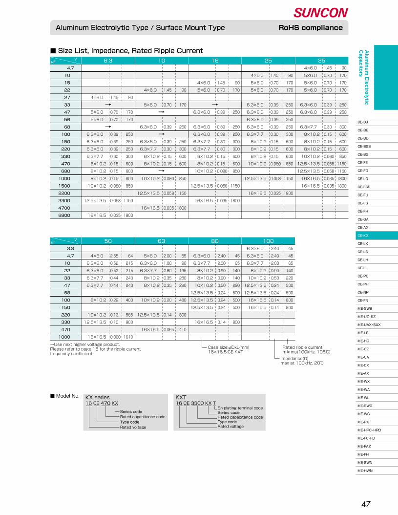
47
■ Size List, Impedance, Rated Ripple Current
→Use next higher voltage product.�Please refer to page 15 for the ripple current �frequency coefficient.
■ Model No.
16 CE 470 KX
Series code�Rated capacitance code�Type code�Rated voltage
16 CE 3300 KX TKX series KXT
Aluminum Electrolytic Type / Surface Mount Type RoHS compliance
μFV 6.3 10 16 25
4×6.0 �
5×6.0 �
5×6.0 �
5×6.0 �
�
6.3×6.0 �
6.3×6.0 �
�
6.3×7.7 �
8×10.2�
8×10.2�
8×10.2�
10×10.2�
12.5×13.5�
12.5×13.5�
16×16.5�
16×16.5
90�
170�
170�
170�
�
250�
250�
�
300�
600�
600�
600�
850�
1150�
1150�
1800�
1800
1.45�
0.70�
0.70�
0.70�
�
0.39�
0.39�
�
0.30�
0.15�
0.15�
0.15�
0.080�
0.058�
0.058�
0.035�
0.035
�
4×6.0 �
5×6.0 �
5×6.0 �
�
6.3×6.0 �
6.3×6.0 �
6.3×6.0 �
6.3×6.0 �
6.3×7.7 �
8×10.2�
8×10.2�
8×10.2�
10×10.2�
�
12.5×13.5�
�
16×16.5
�
90�
170�
170�
�
250�
250�
250�
250�
300�
600�
600�
600�
850�
�
1150�
�
1800
�
1.45�
0.70�
0.70�
�
0.39�
0.39�
0.39�
0.39�
0.30�
0.15�
0.15�
0.15�
0.080�
�
0.058�
�
0.035
�
�
4×6.0 �
5×6.0 �
�
�
6.3×6.0 �
�
6.3×6.0 �
6.3×6.0 �
6.3×7.7 �
6.3×7.7 �
8×10.2�
8×10.2�
10×10.2�
�
12.5×13.5�
�
16×16.5
�
�
90�
170�
�
�
250�
�
250�
250�
300�
300�
600�
600�
850�
�
1150�
�
1800
�
�
1.45�
0.70�
�
�
0.39�
�
0.39�
0.39�
0.30�
0.30�
0.15�
0.15�
0.080�
�
0.058�
�
0.035
�
�
�
4×6.0 �
�
5×6.0 �
�
�
6.3×6.0 �
�
6.3×6.0 �
6.3×7.7 �
8×10.2�
8×10.2�
�
10×10.2�
�
12.5×13.5�
�
16×16.5
�
�
�
90�
�
170�
�
�
250�
�
250�
300�
600�
600�
�
850�
�
1150�
�
1800
�
�
�
1.45�
�
0.70�
�
�
0.39�
�
0.39�
0.30�
0.15�
0.15�
�
0.080�
�
0.058�
�
0.035
�
�
�
�
4×6.0 �
�
5×6.0 �
5×6.0 �
�
6.3×6.0 �
6.3×6.0 �
6.3×6.0 �
6.3×7.7 �
8×10.2�
8×10.2�
8×10.2�
10×10.2�
�
12.5×13.5�
�
16×16.5
�
�
�
�
90�
�
170�
170�
�
250�
250�
250�
300�
600�
600�
600�
850�
�
1150�
�
1800
�
�
�
�
1.45�
�
0.70�
0.70�
�
0.39�
0.39�
0.39�
0.30�
0.15�
0.15�
0.15�
0.080�
�
0.058�
�
0.035
354.7�
10 �
15 �
22 �
27 �
33 �
47 �
56 �
68 �
100 �
150 �
220 �
330 �
470 �
680 �
1000 �
1500 �
2200 �
3300 �
4700 �
6800 �
μFV 50 63 80 100
3.3�
4.7�
10 �
22 �
33 �
47 �
68 �
100 �
150 �
220 �
330 �
470 �
1000 �
6.3×6.0 �
6.3×6.0 �
6.3×7.7 �
8×10.2�
10×10.2�
12.5×13.5�
12.5×13.5�
16×16.5�
16×16.5
45�
45�
65�
140�
220�
500�
500�
800�
800
2.40�
2.40 �
2.00�
0.90�
0.50�
0.24�
0.24�
0.14�
0.14
�
6.3×6.0 �
6.3×7.7 �
8×10.2�
8×10.2�
10×10.2�
12.5×13.5�
12.5×13.5�
12.5×13.5�
�
16×16.5
�
45�
65�
140�
140�
220�
500�
500�
500�
�
800
�
2.40 �
2.00�
0.90�
0.90�
0.50�
0.24�
0.24�
0.24�
�
0.14
�
5×6.0 �
6.3×6.0 �
6.3×7.7 �
8×10.2�
8×10.2�
�
10×10.2�
�
12.5×13.5�
�
16×16.5
�
55�
90�
135�
280�
280�
�
480�
�
800�
�
1410
�
2.00 �
1.00�
0.80�
0.35�
0.35�
�
0.20�
�
0.14�
�
0.065
�
4×6.0 �
6.3×6.0 �
6.3×6.0 �
6.3×7.7 �
6.3×7.7 �
�
8×10.2�
�
10×10.2�
12.5×13.5�
�
16×16.5
�
64�
215�
215�
243�
243�
�
400�
�
585�
800�
�
1610
�
2.55�
0.52�
0.52�
0.44�
0.44�
�
0.22�
�
0.13�
0.10�
�
0.060
Rated ripple current�mArms(100kHz, 105℃)
Case size:φDxL(mm)�16×16.5:CE-KXT
Impedance(Ω)�max at 100kHz, 20℃�
→�
→�
→�→�
→�
→�
Sn plating terminal code�Series code�Rated capacitance code�Type code�Rated voltage
Alu
min
um
Electro
lytic C
apacito
rs
CE-BJ�
CE-BE�
CE-BD�
CE-BSS�
CE-BS�
CE-FE�
CE-FD�
CE-LD�
CE-FSS�
CE-FU�
CE-FS�
CE-FH�
CE-GA�
CE-AX�
CE-KX�
CE-LX�
CE-LS�
CE-LH�
CE-LL�
CE-PC�
CE-PH�
CE-NP�
CE-FN�
ME-SWB�
ME-UZ・SZ�
ME-UAX・SAX�
ME-LS�
ME-HC�
ME-CZ�
ME-CA�
ME-CX�
ME-AX�
ME-WX�
ME-WA�
ME-WL�
ME-SWG�
ME-WG�
ME-PX�
ME-HPC・HPD�
ME-FC・FD�
ME-FAZ�
ME-FH�
ME-SWN�
ME-HWN


50
●105℃, 3,000hrs.� ●Solvent proof (within 2 minutes)
CE-LS Series
■ Marking, Dimensions
■ Specifications
D+0.5max W±0.2� H±0.2� C±0.2� R P±0.2�L±0.3�(Unit : mm)
5 �
6.3�
6.3
6.0�
6.0�
7.7
5.3�
6.6�
6.6
5.3�
6.6�
6.6
6.0�
7.3�
7.3
0.5 to 0.8�
0.5 to 0.8�
0.5 to 0.8
1.4�
2.2�
2.2
10�
22�
33�
47�
100�
150�
220�
330
70�
70�
100
2.00�
2.00�
1.35
6.3μFV 10 16 25 35 50
Please refer to page 15 for the ripple current frequency coefficient. Rated ripple current�mArms(100kHz, 105℃)
Case size:φDxL(mm)
Impedance(Ω)�max at 100kHz, 20℃�
■ Size List, Impedance, Rated Ripple Current
6.3×6.0�
6.3×6.0�
6.3×7.7
95�
140�
�
230
1.30�
0.70�
�
0.60
5×6.0�
6.3×6.0�
�
6.3×7.7
�
95�
140�
140�
230
�
1.30�
0.70�
0.70�
0.60
�
5×6.0�
6.3×6.0�
6.3×6.0�
6.3×7.7
�
95�
�
140�
140�
230�
230
�
1.30�
�
0.70�
0.70�
0.60�
0.60
�
5×6.0�
�
6.3×6.0�
6.3×6.0�
6.3×7.7�
6.3×7.7
�
�
95�
�
�
140
�
�
1.30�
�
�
0.70
�
�
5×6.0�
�
�
6.3×6.0
�
�
�
95�
140�
�
230�
230
�
�
�
1.30�
0.70�
�
0.60�
0.60
�
�
�
5×6.0�
6.3×6.0�
�
6.3×7.7�
6.3×7.7
■ Model No.16 CE 220 LS
Series code�Rated capacitance code�Type code�Rated voltage
Aluminum Electrolytic Type / Surface Mount Type RoHS compliance
Long Life
Low Impedance
Endurance
105℃, 3,000hrs.�rated voltage applied(With the rated�ripple current)
△C/C�
tanδ�
LC
�
-40 to +105�
M : ±20�
�
The greater value of either 0.01CV or 3�
�
�
6.3�
8.0�
�
�
0.28�
�
4�
10
10�
13�
�
�
0.24�
�
3�
7
16�
20�
�
�
0.22�
�
2�
5
25�
32�
�
�
0.16�
�
2�
3
35�
44�
�
�
0.13�
�
2�
3
50�
63�
�
�
0.12�
�
2�
3
SpecificationsConditionItems
Rated voltage�
Surge voltage�
Category temperature range�
Capacitance tolerance�
Dissipation Factor(tanδ)�
Leakage current(LC)�
(V)�
(V)�
(℃)�
(%)
-�
Room temperature�
-�
120Hz/20℃�
120Hz/20℃�
μA/after 2minutes (max)
Within ±30% of the initial value�
≤ 3 times the initial specified value�
≤ The initial specified value
Based the value at�120Hz, +20℃�
Impedance ratio at�low temperature
ー25℃�
ー40℃�
Z/Z20℃�
Z/Z20℃�
16220
S
14
Polarity�(Cathode)
Lot No.
Rated Capacitance
Series Symbol
Rated Voltage(6.3V→6)
0.3max
L
W
(+)R
φD
H P C
Alu
min
um
Electro
lytic C
apacito
rs
CE-BJ�
CE-BE�
CE-BD�
CE-BSS�
CE-BS�
CE-FE�
CE-FD�
CE-LD�
CE-FSS�
CE-FU�
CE-FS�
CE-FH�
CE-GA�
CE-AX�
CE-KX�
CE-LX�
CE-LS�
CE-LH�
CE-LL�
CE-PC�
CE-PH�
CE-NP�
CE-FN�
ME-SWB�
ME-UZ・SZ�
ME-UAX・SAX�
ME-LS�
ME-HC�
ME-CZ�
ME-CA�
ME-CX�
ME-AX�
ME-WX�
ME-WA�
ME-WL�
ME-SWG�
ME-WG�
ME-PX�
ME-HPC・HPD�
ME-FC・FD�
ME-FAZ�
ME-FH�
ME-SWN�
ME-HWN
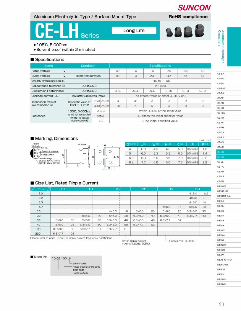
51
●105℃, 5,000hrs.� ●Solvent proof (within 2 minutes)
CE-LH Series
■ Specifications
■ Marking, DimensionsD+0.5max W±0.2� H±0.2� C±0.2� R P±0.2�L±0.3�
(Unit : mm)
4 �
5 �
6.3�
6.3
6.0�
6.0�
6.0�
7.7
4.3�
5.3�
6.6�
6.6
4.3�
5.3�
6.6�
6.6
5.0�
6.0�
7.3�
7.3
0.5 to 0.8�
0.5 to 0.8�
0.5 to 0.8�
0.5 to 0.8
1.0�
1.4�
2.2�
2.2
■ Model No.10 CE 100 LH
Series code�Rated capacitance code�Type code�Rated voltage
1.0 �
2.2 �
3.3 �
4.7 �
10 �
22 �
33 �
47 �
100 �
220 �
μFV 6.3 10 16 25 35 50
4×6.0�
4×6.0�
4×6.0�
5×6.0�
6.3×6.0�
6.3×7.7
�
�
�
4×6.0�
5×6.0�
6.3×6.0�
6.3×7.7
�
�
�
�
5×6.0�
6.3×6.0�
6.3×6.0�
6.3×7.7
�
�
�
�
4×6.0�
5×6.0�
6.3×6.0�
6.3×6.0�
6.3×7.7
�
�
�
�
�
5×6.0�
5×6.0�
6.3×6.0�
6.3×7.7
�
�
�
�
�
�
5×6.0�
5×6.0�
6.3×6.0�
6.3×7.7
�
�
�
�
�
�
35�
36�
60�
101
�
�
�
�
�
30�
35�
50�
81
�
�
�
�
18�
30�
48�
50�
81
�
�
�
�
25�
42�
48�
63
�
�
�
15�
25�
42�
57
6.2�
11 �
14 �
19 �
30 �
49 �
Please refer to page 15 for the ripple current frequency coefficient.Rated ripple current�mArms(120Hz, 105℃)
Case size:φDxL(mm)
■ Size List, Rated Ripple Current
Long Life
Aluminum Electrolytic Type / Surface Mount Type RoHS compliance
Endurance
105℃, 5,000hrs.�rated voltage applied(With the rated�ripple current)
△C/C�
tanδ�
LC
�
-40 to +105�
M : ±20�
�
The greater value of either 0.01CV or 3�
�
�
6.3�
8.0�
�
�
0.32�
�
4�
10
10�
13�
�
�
0.24�
�
3�
7
16�
20�
�
�
0.20�
�
2�
5
25�
32�
�
�
0.16�
�
2�
3
35�
44�
�
�
0.13�
�
2�
3
50�
63�
�
�
0.12�
�
2�
3
SpecificationsConditionItems
Rated voltage�
Surge voltage�
Category temperature range�
Capacitance tolerance�
Dissipation Factor(tanδ)�
Leakage current(LC)�
(V)�
(V)�
(℃)�
(%)
-�
Room temperature�
-�
120Hz/20℃�
120Hz/20℃�
μA/after 2minutes (max)
Within ±30% of the initial value�
≤ 3 times the initial specified value�
≤ The initial specified value
Based the value at�120Hz, +20℃�
Impedance ratio at�low temperature
-25℃�
-40℃�
Z/Z20℃�
Z/Z20℃�
A100
LH
14
Polarity�(Cathode)
Lot No.
Rated Capacitance
Series Symbol
Rated Voltage
0.3max
L
W
(+)R
φD
H P C
6.3V:6, 10V:A, 16V:C�25V:E, 35V:V, 50V:H
Alu
min
um
Electro
lytic C
apacito
rs
CE-BJ�
CE-BE�
CE-BD�
CE-BSS�
CE-BS�
CE-FE�
CE-FD�
CE-LD�
CE-FSS�
CE-FU�
CE-FS�
CE-FH�
CE-GA�
CE-AX�
CE-KX�
CE-LX�
CE-LS�
CE-LH�
CE-LL�
CE-PC�
CE-PH�
CE-NP�
CE-FN�
ME-SWB�
ME-UZ・SZ�
ME-UAX・SAX�
ME-LS�
ME-HC�
ME-CZ�
ME-CA�
ME-CX�
ME-AX�
ME-WX�
ME-WA�
ME-WL�
ME-SWG�
ME-WG�
ME-PX�
ME-HPC・HPD�
ME-FC・FD�
ME-FAZ�
ME-FH�
ME-SWN�
ME-HWN

52
●160 to 400V 105℃, 5,000hrs.� ●Do not clean the capacitors using solvent.
CE-LH Series
105℃ Long Life
Mid. and High Voltage
■ Marking, Dimensions
■ Specifications
D+0.5max W±0.2� H±0.2� C±0.2� R P±0.2�L
(Unit : mm)
8 �
10 �
12.5�
16 �
8.3�
10.3�
12.8�
16.3
8.3�
10.3�
12.8�
16.3
9.0�
11.0�
13.5�
17.3
0.7 to 1.0�
1.0 to 1.4�
1.0 to 1.4�
1.8 to 2.1
3.2�
4.6�
4.6�
7.0
160 CE 10 LH
Series code�Rated capacitance code�Type code�Rated voltage
200 CE 47 LH TLH series LHT■ Model No.
2.2�
3.3�
4.7�
10 �
22 �
33 �
47 �
68 �
82 �
μFV 160 200 400
�
�
�
10×10.5�
12.5×13.5�
12.5×13.5�
16×16.5�
16×16.5�
16×16.5
�
8×10.5�
8×10.5�
10×10.5�
12.5×13.5�
12.5×13.5�
16×16.5�
16×16.5
8×10.5�
10×10.5�
10×10.5�
12.5×13.5�
16×16.5
�
�
�
43�
112�
137�
180�
215�
235
�
31�
37�
43�
112�
137�
180�
215
25�
36�
38�
57�
115
Please refer to page 15 for the ripple current frequency coefficient.Rated ripple current�mArms(120Hz, 105℃)
Case size:φDxL(mm)�16×16.5:CE-LHT
■ Size List, Rated Ripple Current
10.5±0.3�
10.5±0.3�
13.5±0.5�
16.5±0.5�
Aluminum Electrolytic Type / Surface Mount Type RoHS compliance
Endurance
105℃, 5,000hrs.�rated voltage applied(With the rated�ripple current)
△C/C�
tanδ�
LC
200�
250�
-40 to +105�
M : ±20�
0.20�
0.03CV +15�
0.02CV +25�
3�
6
160�
200�
�
�
0.20�
�
�
3�
6
400�
450�
�
�
0.25�
�
�
6�
10
SpecificationsConditionItems
Rated voltage�
Surge voltage�
Category temperature range�
Capacitance tolerance�
Dissipation Factor(tanδ)�
Leakage current(LC)�
(V)�
(V)�
(℃)�
(%)
-�
Room temperature�
-�
120Hz/20℃�
120Hz/20℃�
Within ±30% of the initial value�
≤ 3 times the initial specified value�
≤ The initial specified value
Based the value at�120Hz, +20℃�
μA/after�2minutes (max)
Impedance ratio at�low temperature
ー25℃�
ー40℃�
Z/Z20℃�
Z/Z20℃�
CV ≤ 1,000�
CV > 1,000
★ (160V : 2C, 200V : 2D, 400V : 2G)
10L2C
14
47L2D
Polarity�(Cathode)
[φD≤10]
[φD≥12.5]
Lot No.Rated Capacitance
Series Symbol
Rated Voltage★�
Polarity�(Cathode) Lot No.
Indicated Only φD=16
Rated Capacitance
Series Symbol
Rated Voltage★�
14T
0.3max
L
W
(+)R
φD
H P C
pressure relief vent
Sn plating terminal code�Series code�Rated capacitance code�Type code�Rated voltage
Alu
min
um
Electro
lytic C
apacito
rs
CE-BJ�
CE-BE�
CE-BD�
CE-BSS�
CE-BS�
CE-FE�
CE-FD�
CE-LD�
CE-FSS�
CE-FU�
CE-FS�
CE-FH�
CE-GA�
CE-AX�
CE-KX�
CE-LX�
CE-LS�
CE-LH�
CE-LL�
CE-PC�
CE-PH�
CE-NP�
CE-FN�
ME-SWB�
ME-UZ・SZ�
ME-UAX・SAX�
ME-LS�
ME-HC�
ME-CZ�
ME-CA�
ME-CX�
ME-AX�
ME-WX�
ME-WA�
ME-WL�
ME-SWG�
ME-WG�
ME-PX�
ME-HPC・HPD�
ME-FC・FD�
ME-FAZ�
ME-FH�
ME-SWN�
ME-HWN
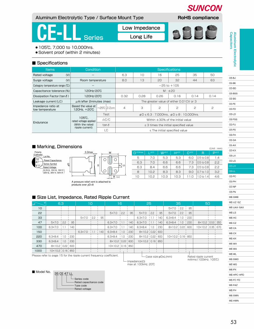
53
CE-LL Series
●105℃, 7,000 to 10,000hrs.� ●Solvent proof (within 2 minutes)
■ Specifications
■ Marking, DimensionsD+0.5max W±0.2� H±0.2� C±0.2� R P±0.2�L±0.3�
(Unit : mm)
5 �
6.3�
6.3�
8 �
10 �
7.0�
7.0�
8.4�
10.2�
10.2
5.3�
6.6�
6.6�
8.3�
10.3
5.3�
6.6�
6.6�
8.3�
10.3
6.0�
7.3�
7.3�
9.0�
11.0
0.5 to 0.8�
0.5 to 0.8�
0.5 to 0.8�
0.7 to 1.0�
1.0 to 1.4
1.4�
2.2�
2.2�
3.2�
4.6
35 CE 47 LL
Series code�Rated capacitance code�Type code�Rated voltage
■ Model No.
10�
22�
33�
47�
100�
150�
220�
330�
470�
1000
6.3μFV 10 16 25 35 50
Please refer to page 15 for the ripple current frequency coefficient. Rated ripple current�mArms(100kHz, 105℃)�
Case size:φDxL(mm)
Impedance(Ω)�max at 100kHz, 20℃�
■ Size List, Impedance, Rated Ripple Current
95�
95�
230�
230�
600�
�
850
2.2 �
2.2 �
1.0 �
1.0 �
0.22�
�
0.16
5×7.0 �
5×7.0 �
6.3×8.4 �
6.3×8.4 �
8×10.2�
�
10×10.2
�
95�
140�
140�
230�
600�
600�
850
�
2.2 �
1.1 �
1.1 �
1.0 �
0.22�
0.22�
0.16
�
5×7.0 �
6.3×7.0 �
6.3×7.0 �
6.3×8.4 �
8×10.2�
8×10.2�
10×10.2
�
95�
�
140�
140�
230�
230�
600�
850
�
2.2 �
�
1.1 �
1.1 �
1.0 �
1.0 �
0.22�
0.16
�
5×7.0 �
�
6.3×7.0 �
6.3×7.0 �
6.3×8.4 �
6.3×8.4 �
8×10.2�
10×10.2
�
�
95�
�
�
140
�
�
2.2 �
�
�
1.1 �
�
�
5×7.0 �
�
�
6.3×7.0 �
�
�
�
95�
140�
�
230�
230�
600�
850
�
�
�
2.2 �
1.1 �
�
1.0 �
1.0 �
0.22�
0.16
�
�
�
5×7.0 �
6.3×7.0 �
�
6.3×8.4 �
6.3×8.4 �
8×10.2�
10×10.2
�
�
�
350�
670
�
�
�
0.53�
0.35
�
�
�
8×10.2�
10×10.2
Long Life
Low Impedance
Aluminum Electrolytic Type / Surface Mount Type RoHS compliance
Endurance
Impedance ratio at�low temperature
Based the value at�120Hz, +20℃�
Test�
△C/C�
tanδ�
LC
ー25℃�Z/Z20℃�
�
�
-25 to +105�
M : ±20�
�
The greater value of either 0.01CV or 3
6.3�
8.0�
�
�
0.32
10�
13�
�
�
0.28
16�
20�
�
�
0.26
25�
32�
�
�
0.16
35�
44�
�
�
0.14�
�
50�
63�
�
�
0.14
4 3 2 2 2 2
SpecificationsConditionItems
Rated voltage�
Surge voltage�
Category temperature range�
Capacitance tolerance�
Dissipation Factor(tanδ)�
Leakage current(LC)�
(V)�
(V)�
(℃)�
(%)
-�
Room temperature�
-�
120Hz/20℃�
120Hz/20℃�
μA/after 2minutes (max)
φD ≤ 6.3 : 7,000hrs., φD ≥ 8 : 10,000hrs.�
Within ±30% of the initial value�
≤ 3 times the initial specified value�
≤ The initial specified value
105℃,�rated voltage applied(With the rated�ripple current)
Polarity�(Cathode)
Lot No.
Rated Capacitance
Series Symbol
Rated Voltage
0.3max
L
W
(+)R
φD��
H� � P C
1447
LLV
6.3V:6, 10V:A, 16V:C�25V:E, 35V:V, 50V:H
A pressure relief vent is attached to �products over φD=8
Alu
min
um
Electro
lytic C
apacito
rs
CE-BJ�
CE-BE�
CE-BD�
CE-BSS�
CE-BS�
CE-FE�
CE-FD�
CE-LD�
CE-FSS�
CE-FU�
CE-FS�
CE-FH�
CE-GA�
CE-AX�
CE-KX�
CE-LX�
CE-LS�
CE-LH�
CE-LL�
CE-PC�
CE-PH�
CE-NP�
CE-FN�
ME-SWB�
ME-UZ・SZ�
ME-UAX・SAX�
ME-LS�
ME-HC�
ME-CZ�
ME-CA�
ME-CX�
ME-AX�
ME-WX�
ME-WA�
ME-WL�
ME-SWG�
ME-WG�
ME-PX�
ME-HPC・HPD�
ME-FC・FD�
ME-FAZ�
ME-FH�
ME-SWN�
ME-HWN
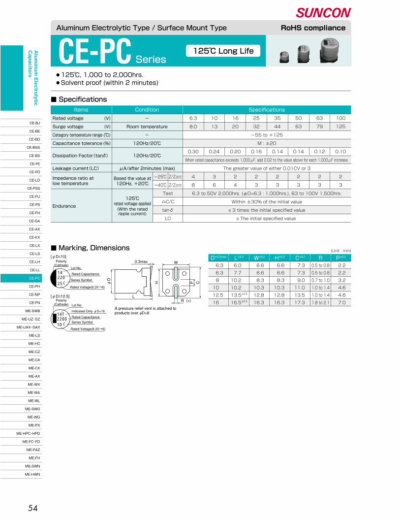
54
●125℃, 1,000 to 2,000hrs.� ●Solvent proof (within 2 minutes)
CE-PC Series
■ Marking, Dimensions
■ Specifications
125℃ Long Life
D+0.5max W±0.2� H±0.2� C±0.2� R P±0.2�L±0.3�(Unit : mm)
6.3�
6.3�
8 �
10 �
12.5�
16 �
6.6�
6.6�
8.3�
10.3�
12.8�
16.3
6.6�
6.6�
8.3�
10.3�
12.8�
16.3
7.3�
7.3�
9.0�
11.0�
13.5�
17.3
2.2�
2.2�
3.2�
4.6�
4.6�
7.0
0.5 to 0.8�
0.5 to 0.8�
0.7 to 1.0�
1.0 to 1.4�
1.0 to 1.4�
1.8 to 2.1
6.0 �
7.7 �
10.2 �
10.2 �
13.5±0.5�
16.5±0.5�
Aluminum Electrolytic Type / Surface Mount Type RoHS compliance
Endurance
125℃�rated voltage applied(With the rated�ripple current)
Test�
△C/C�
tanδ�
LC
ー25℃�
ー40℃�
Z/Z20℃�
Z/Z20℃�
�
-55 to +125�
M : ±20�
�
When rated capacitance exceeds 1,000μF, add 0.02 to the value above for each 1,000μF increase.�
The greater value of either 0.01CV or 3�
�
�
6.3�
8.0�
�
�
0.30�
�
�
4�
8
10�
13�
�
�
0.24�
�
�
3�
6
16�
20�
�
�
0.20�
�
�
2�
4
25�
32�
�
�
0.16�
�
�
2�
3
35�
44�
�
�
0.14�
�
�
2�
3
50�
63�
�
�
0.14�
�
�
2�
3
63�
79�
�
�
0.12�
�
�
2�
3
100�
125�
�
�
0.10�
�
�
2�
3
SpecificationsConditionItems
Rated voltage�
Surge voltage�
Category temperature range�
Capacitance tolerance�
Dissipation Factor(tanδ)��
Leakage current(LC)�
�
�
(V)�
(V)�
(℃)�
(%)
-�
Room temperature�
-�
120Hz/20℃�
120Hz/20℃�
�
μA/after 2minutes (max)
6.3 to 50V 2,000hrs. (φD=6.3 : 1,000hrs.), 63 to 100V 1,500hrs.�
Within ±30% of the initial value�
≤ 3 times the initial specified value�
≤ The initial specified value
Based the value at�120Hz, +20℃�
Impedance ratio at�low temperature
220C25
14
2200C10
14T
Polarity�(Cathode)
Lot No.
Rated Capacitance
Series Symbol
Rated Voltage(6.3V→6)
Polarity�(Cathode) Lot No.
Indicated Only φD=16
Rated Capacitance
Series Symbol
Rated Voltage(6.3V→6)
[φD≤10]
[φD≥12.5]
0.3max
L
W
(+)R
φD
H P C
A pressure relief vent is attached to �products over φD=8
Alu
min
um
Electro
lytic C
apacito
rs
CE-BJ�
CE-BE�
CE-BD�
CE-BSS�
CE-BS�
CE-FE�
CE-FD�
CE-LD�
CE-FSS�
CE-FU�
CE-FS�
CE-FH�
CE-GA�
CE-AX�
CE-KX�
CE-LX�
CE-LS�
CE-LH�
CE-LL�
CE-PC�
CE-PH�
CE-NP�
CE-FN�
ME-SWB�
ME-UZ・SZ�
ME-UAX・SAX�
ME-LS�
ME-HC�
ME-CZ�
ME-CA�
ME-CX�
ME-AX�
ME-WX�
ME-WA�
ME-WL�
ME-SWG�
ME-WG�
ME-PX�
ME-HPC・HPD�
ME-FC・FD�
ME-FAZ�
ME-FH�
ME-SWN�
ME-HWN
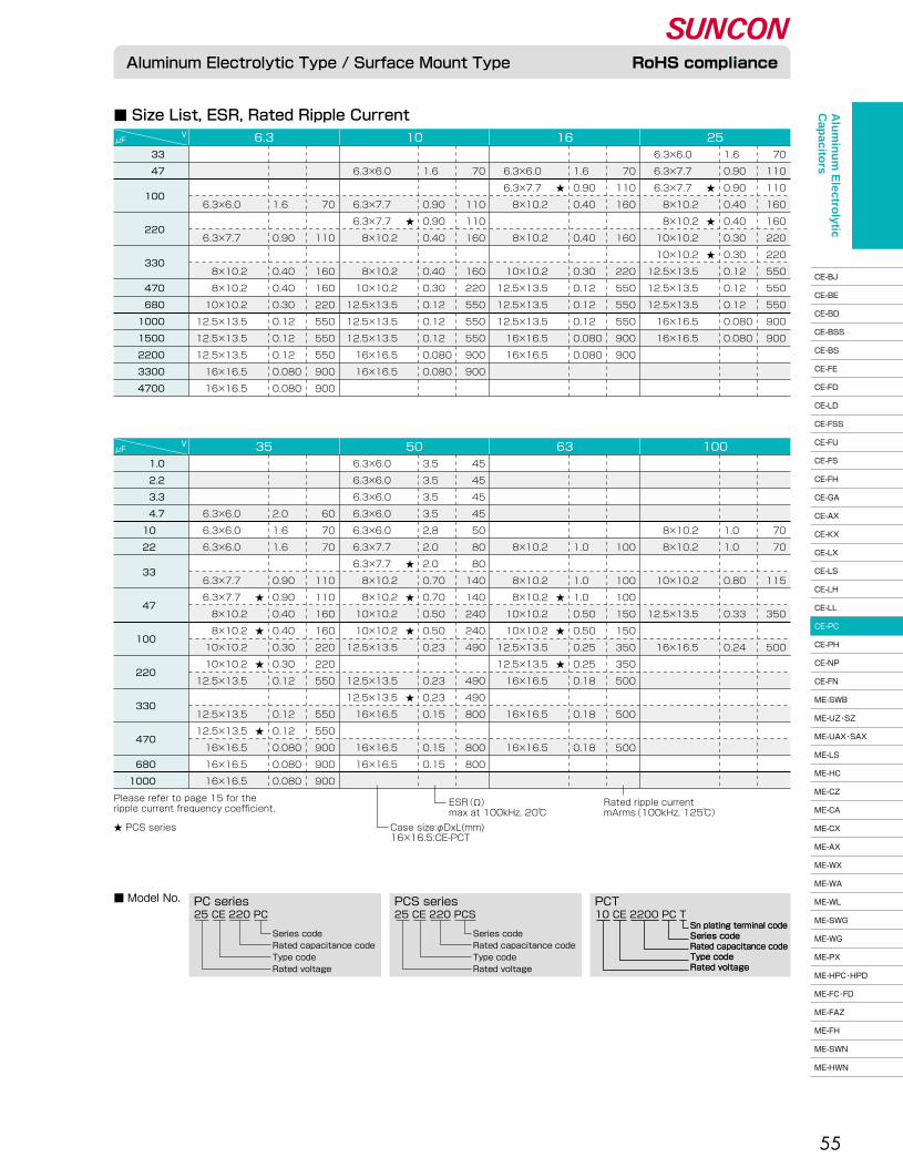
55
■ Size List, ESR, Rated Ripple Current
■ Model No.
25 CE 220 PCS
Series code�Rated capacitance code�Type code�Rated voltage
25 CE 220 PC
Series code�Rated capacitance code�Type code�Rated voltage
10 CE 2200 PC TPCS seriesPC series PCT
Aluminum Electrolytic Type / Surface Mount Type RoHS compliance
Sn plating terminal code�Series code�Rated capacitance code�Type code�Rated voltage
Sn plating terminal code�Series code�Rated capacitance code�Type code�Rated voltage
★�
★�
★�
★�
★�
★�
★�
★�
★�
★�
★�
★�
★�
★�
★�★�
33�
47�
100�
�
220�
�
330� �
470�
680�
1000�
1500�
2200�
3300�
4700
μFV 6.3 10 16 25
6.3×6.0 �
6.3×7.7 �
6.3×7.7 �
8×10.2�
8×10.2�
10×10.2�
10×10.2�
12.5×13.5�
12.5×13.5�
12.5×13.5�
16×16.5�
16×16.5
1.6�
0.90�
0.90�
0.40�
0.40�
0.30�
0.30�
0.12�
0.12�
0.12�
0.080 �
0.080
70�
110�
110�
160�
160�
220�
220�
550�
550�
550�
900�
900
�
6.3×6.0 �
6.3×7.7 �
8×10.2�
�
8×10.2�
�
10×10.2�
12.5×13.5�
12.5×13.5�
12.5×13.5�
16×16.5�
16×16.5
�
1.6�
0.90�
0.40�
�
0.40�
�
0.30�
0.12�
0.12�
0.12�
0.080 �
0.080
�
70�
110�
160�
�
160�
�
220�
550�
550�
550�
900�
900
�
6.3×6.0 �
�
6.3×7.7 �
6.3×7.7 �
8×10.2�
�
8×10.2�
10×10.2�
12.5×13.5�
12.5×13.5�
12.5×13.5�
16×16.5�
16×16.5
�
1.6�
�
0.90�
0.90�
0.40�
�
0.40�
0.30�
0.12�
0.12�
0.12�
0.080 �
0.080
�
70�
�
110�
110�
160�
�
160�
220�
550�
550�
550�
900�
900
�
�
�
6.3×6.0 �
�
6.3×7.7 �
�
8×10.2�
8×10.2�
10×10.2�
12.5×13.5�
12.5×13.5�
12.5×13.5�
16×16.5�
16×16.5
�
�
�
1.6�
�
0.90�
�
0.40�
0.40�
0.30�
0.12�
0.12�
0.12�
0.080 �
0.080
�
�
�
70�
�
110�
�
160�
160�
220�
550�
550�
550�
900�
900
1.0�
2.2�
3.3�
4.7�
10 �
22 �
33 �
�
47 �
�
100 �
�
220 �
�
330 �
�
470 � �
680 �
1000 �
μFV 35 50 63 100
�
�
�
�
8×10.2�
8×10.2�
�
10×10.2�
�
12.5×13.5�
�
16×16.5
�
�
�
�
1.0�
1.0�
�
0.80�
�
0.33�
�
0.24
�
�
�
�
70�
70�
�
115�
�
350�
�
500
�
�
�
�
�
8×10.2�
�
8×10.2�
8×10.2�
10×10.2�
10×10.2�
12.5×13.5�
12.5×13.5�
16×16.5�
�
16×16.5�
�
16×16.5
�
�
�
�
�
1.0�
�
1.0�
1.0�
0.50�
0.50�
0.25�
0.25�
0.18�
�
0.18�
�
0.18
�
�
�
�
�
100�
�
100�
100�
150�
150�
350�
350�
500�
�
500�
�
500
6.3×6.0 �
6.3×6.0 �
6.3×6.0 �
6.3×6.0 �
6.3×6.0 �
6.3×7.7 �
6.3×7.7 �
8×10.2�
8×10.2�
10×10.2�
10×10.2�
12.5×13.5�
�
12.5×13.5�
12.5×13.5�
16×16.5�
�
16×16.5�
16×16.5
3.5�
3.5�
3.5�
3.5�
2.8�
2.0�
2.0�
0.70�
0.70�
0.50�
0.50�
0.23�
�
0.23�
0.23�
0.15�
�
0.15�
0.15
45�
45�
45�
45�
50�
80�
80�
140�
140�
240�
240�
490�
�
490�
490�
800�
�
800�
800
�
�
�
6.3×6.0 �
6.3×6.0 �
6.3×6.0 �
�
6.3×7.7 �
6.3×7.7 �
8×10.2�
8×10.2�
10×10.2�
10×10.2�
12.5×13.5�
�
12.5×13.5�
12.5×13.5�
16×16.5�
16×16.5�
16×16.5
�
�
�
2.0�
1.6�
1.6�
�
0.90�
0.90�
0.40�
0.40�
0.30�
0.30�
0.12�
�
0.12�
0.12�
0.080 �
0.080 �
0.080
�
�
�
60�
70�
70�
�
110�
110�
160�
160�
220�
220�
550�
�
550�
550�
900�
900�
900
Rated ripple current�mArms(100kHz, 125℃)�
ESR(Ω)�max at 100kHz, 20℃�
Case size:φDxL(mm)�16×16.5:CE-PCT
★ PCS series
Please refer to page 15 for the �ripple current frequency coefficient.
Alu
min
um
Electro
lytic C
apacito
rs
CE-BJ�
CE-BE�
CE-BD�
CE-BSS�
CE-BS�
CE-FE�
CE-FD�
CE-LD�
CE-FSS�
CE-FU�
CE-FS�
CE-FH�
CE-GA�
CE-AX�
CE-KX�
CE-LX�
CE-LS�
CE-LH�
CE-LL�
CE-PC�
CE-PH�
CE-NP�
CE-FN�
ME-SWB�
ME-UZ・SZ�
ME-UAX・SAX�
ME-LS�
ME-HC�
ME-CZ�
ME-CA�
ME-CX�
ME-AX�
ME-WX�
ME-WA�
ME-WL�
ME-SWG�
ME-WG�
ME-PX�
ME-HPC・HPD�
ME-FC・FD�
ME-FAZ�
ME-FH�
ME-SWN�
ME-HWN

56
●125℃, 2,000 to 3,000hrs. ● Suitable for Automotive Application� ●Solvent proof (within 2 minutes)
CE-PH Series
125℃ Low ESR
High Ripple, High Capacitance
■ Size List, ESR, Rated Ripple Current
■ Marking, Dimensions
■ Specifications
(Unit : mm)
■ Model No.
16 CE 680 PH
Series code�Rated capacitance code�Type code�Rated voltage
35 CE 1000 PH TPH series PHT
Aluminum Electrolytic Type / Surface Mount Type RoHS compliance
Endurance
125℃�rated voltage applied(With the rated�ripple current)
Test�
△C/C�
tanδ�
LC
25�
32�
-40 to +125�
M : ±20�
0.16�
When rated capacitance exceeds 1,000μF, add 0.02 to the value above for each 1,000μF increase.�
0.01CV�
2�
3
16�
20�
�
�
0.20�
�
�
2�
4
35�
44�
�
�
0.14�
�
�
2�
3
SpecificationsConditionItems
Rated voltage�
Surge voltage�
Category temperature range�
Capacitance tolerance�
Dissipation Factor(tanδ)�
�Leakage current(LC)�
(V)�
(V)�
(℃)�
(%)
-�
Room temperature�
-�
120Hz/20℃�
120Hz/20℃��
μA/after 2minutes (max)�
�
φ8 to φ12.5 : 2,000hrs., φ16, φ18 : 3,000hrs.�
Within ±30% of the initial value�
≤ 3 times the initial specified value�
≤ The initial specified value
Based the value at�120Hz, +20℃�
Impedance ratio at�low temperature
ー25℃�
ー40℃�
Z/Z20℃�
Z/Z20℃�
★ (16V:C, 25V:E, 35V:V)
680PHC
14
1000PHV
Polarity�(Cathode)
[φD≤10]
[φD≥12.5]
Lot No.Rated Capacitance
Series Symbol
Rated Voltage★�
Polarity�(Cathode) Lot No.
Rated Capacitance
Series Symbol
Rated Voltage★�
14T
0.3max
L
W
(+)R
φD
H P C
pressure relief ventIndicated φD=16, 18
φ18×16.5
D+0.5max W±0.2� H±0.2� C±0.2� R P±0.2�L8 �
10 �
12.5�
16 �
18
10.5±0.3�
10.5±0.3�
13.5±0.5�
16.5±0.5�
16.5±1.0�
8.3�
10.3�
12.8�
16.3�
19.0
8.3�
10.3�
12.8�
16.3�
19.0
9.0�
11.0�
13.5�
17.3�
20.0
0.7 to 1.0�
1.0 to 1.4�
1.0 to 1.4�
1.8 to 2.1�
1.7 to 2.1
3.2�
4.6�
4.6�
7.0�
7.0
Sn plating terminal code�Series code�Rated capacitance code�Type code�Rated voltage
100�
160�
220�
270�
300�
330�
390�
470�
620�
680�
910�
1000�
1500�
2200�
3300
μFV 16 25 35
8×10.5�
8×10.5�
10×10.5�
�
10×10.5�
�
�
12.5×13.5�
12.5×13.5�
16×16.5�
�
16×16.5�
18×16.5
300�
300�
500�
�
500�
�
�
1200�
1200�
1800�
�
1800�
2000
3.0�
3.0�
2.0�
�
2.0�
�
�
1.0�
1.0�
0.5�
�
0.5�
0.45
0.18�
0.18�
0.11�
�
0.11�
�
�
0.08�
0.08�
0.05�
�
0.05�
0.045
�
�
8×10.5�
8×10.5�
�
10×10.5�
�
10×10.5�
�
12.5×13.5�
12.5×13.5�
16×16.5�
16×16.5�
18×16.5
�
�
300�
300�
�
500�
�
500�
�
1200�
1200�
1800�
1800�
2000
�
�
3.0�
3.0�
�
2.0�
�
2.0�
�
1.0�
1.0�
0.5�
0.5�
0.45
�
�
0.18�
0.18�
�
0.11�
�
0.11�
�
0.08�
0.08�
0.05�
0.05�
0.045
�
�
�
�
�
8×10.5�
8×10.5�
10×10.5�
�
10×10.5�
�
12.5×13.5�
12.5×13.5�
16×16.5�
18×16.5
�
�
�
�
�
300�
300�
500�
�
500�
�
1200�
1200�
1800�
2000
�
�
�
�
�
3.0�
3.0�
2.0�
�
2.0�
�
1.0�
1.0�
0.5�
0.45
�
�
�
�
�
0.18�
0.18�
0.11�
�
0.11�
�
0.08�
0.08�
0.05�
0.045
Please refer to page 15 for the ripple �current frequency coefficient.
Rated ripple current�mArms(100kHz, 125℃)�
Case size:φDxL(mm)�16×16.5, 18×16.5:CE-PHT
ESR(Ω)�max at 100kHz, 20℃�
ESR(Ω)�max at 100kHz, -40℃�
Alu
min
um
Electro
lytic C
apacito
rs
CE-BJ�
CE-BE�
CE-BD�
CE-BSS�
CE-BS�
CE-FE�
CE-FD�
CE-LD�
CE-FSS�
CE-FU�
CE-FS�
CE-FH�
CE-GA�
CE-AX�
CE-KX�
CE-LX�
CE-LS�
CE-LH�
CE-LL�
CE-PC�
CE-PH�
CE-NP�
CE-FN�
ME-SWB�
ME-UZ・SZ�
ME-UAX・SAX�
ME-LS�
ME-HC�
ME-CZ�
ME-CA�
ME-CX�
ME-AX�
ME-WX�
ME-WA�
ME-WL�
ME-SWG�
ME-WG�
ME-PX�
ME-HPC・HPD�
ME-FC・FD�
ME-FAZ�
ME-FH�
ME-SWN�
ME-HWN

57
CE-NPSeries
Bi-polar
5.4mm Height
●85℃, 2,000hrs.� ●Solvent proof (within 2 minutes)
■ Specifications
■ Marking, Dimensions
■ Size List, Rated Ripple Current
D+0.5max W±0.2� H±0.2� C±0.2� R P±0.2�L +0.1�-0.2�
(Unit : mm)
4 �
5 �
6.3
5.4�
5.4�
5.4
4.3�
5.3�
6.6
4.3�
5.3�
6.6
5.0�
6.0�
7.3
0.5 to 0.8�
0.5 to 0.8�
0.5 to 0.8
1.0�
1.4�
2.2
1.0 �
2.2 �
3.3 �
4.7 �
10 �
22 �
33 �
47 �
μFV 6.3 10 16 25 35 50
4 �
5 �
5 �
6.3�
6.3
10 �
15 �
18 �
23 �
23 �
�
4 �
5 �
5 �
6.3
�
8.4�
17 �
20 �
30 �
�
�
4 �
5 �
6.3
�
�
10 �
19 �
28 �
�
�
�
4 �
5 �
6.3�
6.3
�
�
�
12 �
25 �
39 �
57 �
�
�
�
�
4 �
6.3�
6.3
�
�
�
�
17 �
35 �
43 �
�
�
�
�
�
5 �
6.3�
6.3
�
�
�
�
�
31 �
39 �
47 �
Please refer to page 15 for the ripple current frequency coefficient.Rated ripple current�mArms(120Hz, 85℃)�
Case size:φD(mm)
16 CE 10 NP
Series code�Rated capacitance code�Type code�Rated voltage
■ Model No.
Aluminum Electrolytic Type / Surface Mount Type RoHS compliance
Endurance(With the rated�ripple current)
△C/C�
tanδ�
LC
�
-40 to +85�
M : ±20�
�
0.03CV + 6�
�
6.3�
8.0�
�
�
0.26�
�
4�
8
10�
13�
�
�
0.22�
�
3�
6
16�
20�
�
�
0.20�
�
2�
4
25�
32�
�
�
0.20�
�
2�
4
35�
44�
�
�
0.20�
�
2�
3
50�
63�
�
�
0.18�
�
2�
3
SpecificationsConditionItems
Rated voltage�
Surge voltage�
Category temperature range�
Capacitance tolerance�
Dissipation Factor(tanδ)�
Leakage current(LC)�
(V)�
(V)�
(℃)�
(%)
-�
Room temperature�
-�
120Hz/20℃�
120Hz/20℃�
μA/after 1minute (max)
Within ±25% of the initial value�
≤ 2 times the initial specified value�
≤ The initial specified value
500hrs.×4(alternately)�85℃,rated voltage applied
Based the value at�120Hz, +20℃�
Impedance ratio at�low temperature
ー25℃�
ー40℃�
Z/Z20℃�
Z/Z20℃�
Lot No.
Rated Capacitance
Series Symbol
Rated Voltage(6.3V→6)
0.3max
L
W
R
φD H� � P C
1016N
14
Alu
min
um
Electro
lytic C
apacito
rs
CE-BJ�
CE-BE�
CE-BD�
CE-BSS�
CE-BS�
CE-FE�
CE-FD�
CE-LD�
CE-FSS�
CE-FU�
CE-FS�
CE-FH�
CE-GA�
CE-AX�
CE-KX�
CE-LX�
CE-LS�
CE-LH�
CE-LL�
CE-PC�
CE-PH�
CE-NP�
CE-FN�
ME-SWB�
ME-UZ・SZ�
ME-UAX・SAX�
ME-LS�
ME-HC�
ME-CZ�
ME-CA�
ME-CX�
ME-AX�
ME-WX�
ME-WA�
ME-WL�
ME-SWG�
ME-WG�
ME-PX�
ME-HPC・HPD�
ME-FC・FD�
ME-FAZ�
ME-FH�
ME-SWN�
ME-HWN

58
●105℃, 1,000hrs.� ●Solvent proof (within 2 minutes)
CE-FN Series
Bi-polar 105℃�
5.4mm Height
■ Marking, Dimensions
■ Specifications
D+0.5max W±0.2� H±0.2� C±0.2� R P±0.2�L +0.1�-0.2�
(Unit : mm)
4 �
5 �
6.3
5.4�
5.4�
5.4
4.3�
5.3�
6.6
4.3�
5.3�
6.6
5.0�
6.0�
7.3
0.5 to 0.8�
0.5 to 0.8�
0.5 to 0.8
1.0�
1.4�
2.2
16 CE 10 FN
Series code�Rated capacitance code�Type code�Rated voltage
■ Model No.
1.0 �
2.2 �
3.3 �
4.7 �
10 �
22 �
33 �
47 �
�
�
�
�
�
22�
27�
33
6.3μFV 10 16 25 35 50 63
�
�
�
�
12�
25�
30
�
�
�
8.0�
17 �
27 �
40 �
�
�
7.0�
13 �
20 �
�
5.9�
12 �
14 �
21 �
7.0�
10 �
13 �
16 �
7.0�
10 �
13 �
16 �
�
�
�
�
�
5 �
6.3�
6.3
�
�
�
�
4 �
6.3�
6.3
�
�
�
4 �
5 �
6.3�
6.3
�
�
4 �
5 �
6.3
�
4 �
5 �
5 �
6.3
4 �
5 �
5 �
6.3
4 �
5 �
6.3�
6.3
Please refer to page 15 for the ripple current frequency coefficient.Rated ripple current�mArms(120Hz, 105℃)�
Case size:φD(mm)
■ Size List, Rated Ripple Current
Aluminum Electrolytic Type / Surface Mount Type RoHS compliance
Endurance
△C/C�
tanδ�
LC
25�
32�
-55 to +105�
M : ±20�
0.20�
0.03CV + 6�
2�
4
6.3�
8.0�
�
�
0.24�
�
3�
8
10�
13�
�
�
0.22�
�
3�
6
16�
20�
�
�
0.20�
�
2�
4
35�
44�
�
�
0.20�
�
2�
3
50�
63�
�
�
0.18�
�
2�
3
63�
79�
�
�
0.16�
�
2�
3
SpecificationsConditionItems
Rated voltage�
Surge voltage�
Category temperature range�
Capacitance tolerance�
Dissipation Factor(tanδ)�
Leakage current(LC)�
(V)�
(V)�
(℃)�
(%)
-�
Room temperature�
-�
120Hz/20℃�
120Hz/20℃�
μA/after 1minute (max)
Within ±25% of the initial value�
≤ 2 times the initial specified value�
≤ The initial specified value (With the rated�ripple current)
500hrs.×2(alternately)�105℃,rated voltage applied
Based the value at�120Hz, +20℃�
Impedance ratio at�low temperature
ー40℃�
ー55℃�
Z/Z20℃�
Z/Z20℃�
Lot No.
Rated Capacitance
Series Symbol
Rated Voltage(6.3V→6)
0.3max
L
W
R
φD
H P C1610
F
14
Alu
min
um
Electro
lytic C
apacito
rs
CE-BJ�
CE-BE�
CE-BD�
CE-BSS�
CE-BS�
CE-FE�
CE-FD�
CE-LD�
CE-FSS�
CE-FU�
CE-FS�
CE-FH�
CE-GA�
CE-AX�
CE-KX�
CE-LX�
CE-LS�
CE-LH�
CE-LL�
CE-PC�
CE-PH�
CE-NP�
CE-FN�
ME-SWB�
ME-UZ・SZ�
ME-UAX・SAX�
ME-LS�
ME-HC�
ME-CZ�
ME-CA�
ME-CX�
ME-AX�
ME-WX�
ME-WA�
ME-WL�
ME-SWG�
ME-WG�
ME-PX�
ME-HPC・HPD�
ME-FC・FD�
ME-FAZ�
ME-FH�
ME-SWN�
ME-HWN
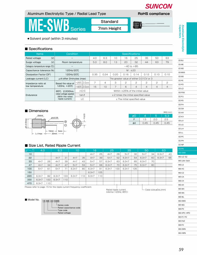
59
●Solvent proof (within 3 minutes)
ME-SWBSeries
■ Dimensions
■ Size List, Rated Ripple Current
■ Specifications
φd±0.05 F±0.5sleeve
L+1max15min20min
5min
φD+0.5max
φD 4F�
φd
1.5 �
0.45
52.0 �
0.45
6.32.5 �
0.45
(単位:mm)�
10�
22�
33�
47�
100�
150�
220�
330�
470
μFV 6350352516106.34.0
Please refer to page 15 for the ripple current frequency coefficient.Rated ripple current�mArms(120Hz, 85℃)�
Case size:φDxL(mm)
34�
60�
70�
80
5×7�
6.3×7�
6.3×7�
6.3×7
30�
54�
65�
75�
105
5×7�
6.3×7�
6.3×7�
6.3×7�
6.3×7
28�
52�
63�
70�
100
4×7�
5×7�
6.3×7�
6.3×7�
6.3×7
25�
39�
57�
68�
91�
105�
110
4×7�
4×7�
5×7�
5×7�
6.3×7�
6.3×7�
6.3×7
�
35�
43�
59�
80�
�
110
�
4×7�
4×7�
5×7�
6.3×7�
�
6.3×7
�
31�
39�
47�
71�
�
103�
110
�
4×7�
4×7�
4×7�
5×7�
�
6.3×7�
6.3×7
�
�
26�
34�
61�
�
82�
100�
110
�
�
4×7�
4×7�
5×7�
�
6.3×7�
6.3×7�
6.3×7
43�
65
6.3×7�
6.3×7
16 ME 33 SWB
Series code�Rated capacitance code�Type code�Rated voltage
■ Model No.
Aluminum Electrolytic Type / Radial Lead Type RoHS compliance
Standard
7mm Height
Endurance
85℃, 2,000hrs.�rated voltage applied(With the rated�ripple current)
Impedance ratio at�low temperature
Based the value at�120Hz, +20℃�
△C/C�
tanδ�
LC
ー25℃�
ー40℃�
Z/Z20℃�
Z/Z20℃�
�
-40 to +85�
M : ±20�
�
The greater value of either 0.01CV or 3�
�
�
4.0�
5.0�
�
�
0.35�
�
7�
15
6.3�
8.0�
�
�
0.24�
�
4�
10
10�
13�
�
�
0.20�
�
3�
7
16�
20�
�
�
0.16�
�
2�
6
25�
32�
�
�
0.14�
�
2�
4
35�
44�
�
�
0.12�
�
2�
4
50�
63�
�
�
0.10�
�
2�
4
63�
79�
�
�
0.10�
�
2�
4
SpecificationsConditionItems
Rated voltage�
Surge voltage�
Category temperature range�
Capacitance tolerance�
Dissipation Factor(DF)�
Leakage current(LC)�
(V)�
(V)�
(℃)�
(%)
-�
Room temperature�
-�
120Hz/20℃�
120Hz/20℃�
μA/after 2minutes (max)
Within ±25% of the initial value�
≤ 2 times the initial specified value�
≤ The initial specified value
Alu
min
um
Electro
lytic C
apacito
rs
CE-BJ�
CE-BE�
CE-BD�
CE-BSS�
CE-BS�
CE-FE�
CE-FD�
CE-LD�
CE-FSS�
CE-FU�
CE-FS�
CE-FH�
CE-GA�
CE-AX�
CE-KX�
CE-LX�
CE-LS�
CE-LH�
CE-LL�
CE-PC�
CE-PH�
CE-NP�
CE-FN�
ME-SWB�
ME-UZ・SZ�
ME-UAX・SAX�
ME-LS�
ME-HC�
ME-CZ�
ME-CA�
ME-CX�
ME-AX�
ME-WX�
ME-WA�
ME-WL�
ME-SWG�
ME-WG�
ME-PX�
ME-HPC・HPD�
ME-FC・FD�
ME-FAZ�
ME-FH�
ME-SWN�
ME-HWN

60
ME-UZ・SZ Series
5mm Height, Temperature of Wide Range
7mm Height, Temperature of Wide Range
●ME-UZ : 105℃, 1,000hrs., Solvent proof (within 2 minutes)� ●ME-SZ : 105℃, 1,000hrs., Solvent proof (within 3 minutes)
■ Specifications
■ Dimensions
■ Size List, Impedance, Rated Ripple Current●UZ siries
φD 4F�
φd
1.5 �
0.45
52.0 �
0.45
6.32.5 �
0.45
(Unit : mm)
16 ME 33 UZSeries code�Rated capacitance code�Type code�Rated voltage
UZ �series
16 ME 10 SZSeries code�Rated capacitance code�Type code�Rated voltage
SZ �series
■ Model No.
10 �
22 �
33 �
47 �
100 �
220 �
μFV 6.3 10 16 25 35 50
6.3×5�
6.3×5
70�
70
2.0�
2.0
●SZ series
1.0 �
2.2 �
3.3 �
4.7 �
10 �
22 �
33 �
47 �
100 �
220 �
330 �
μFV 6.3 10 16 25 35 50
4×7�
4×7�
4×7�
5×7�
6.3×7�
6.3×7�
6.3×7�
6.3×7
30�
35�
40�
70�
100�
100�
100�
100
10 �
7.8�
6.2�
3.1�
1.6�
1.6�
1.6�
1.6
�
6.3×5�
6.3×5�
6.3×5
�
70�
70�
70
�
2.0�
2.0�
2.0
�
�
�
4×7�
5×7�
6.3×7�
6.3×7�
6.3×7�
6.3×7
�
�
�
40�
70�
100�
100�
100�
100
�
�
�
6.0�
3.1�
1.6�
1.6�
1.6�
1.6
�
6.3×5�
6.3×5�
6.3×5
�
100�
100�
100
�
1.6�
1.6�
1.6
�
�
�
4×7�
5×7�
6.3×7�
6.3×7�
6.3×7�
6.3×7
�
�
�
50�
85�
120�
120�
120�
120
�
�
�
4.2�
2.0�
1.2�
1.2�
1.2�
1.2
�
�
6.3×5�
6.3×5�
6.3×5
�
�
100�
100�
100
�
�
1.6�
1.6�
1.6
�
�
�
�
4×7�
5×7�
6.3×7�
6.3×7�
6.3×7�
6.3×7
�
�
�
�
50�
85�
120�
120�
120�
120
�
�
�
�
4.2�
2.0�
1.2�
1.2�
1.2�
1.2
�
�
�
6.3×5�
6.3×5
�
�
�
100�
100
�
�
�
1.6�
1.6
�
�
�
�
�
5×7�
5×7�
6.3×7�
6.3×7�
6.3×7
�
�
�
�
�
85�
85�
120�
120�
120
�
�
�
�
�
2.0�
2.0�
1.2�
1.2�
1.2
�
�
�
�
6.3×5�
6.3×5
�
�
�
�
100�
100
�
�
�
�
1.6�
1.6
�
�
�
�
�
4×7�
5×7�
5×7�
6.3×7�
6.3×7�
6.3×7
�
�
�
�
�
50�
85�
85�
120�
120�
120
�
�
�
�
�
4.2�
2.0�
2.0�
1.2�
1.2�
1.2
Please refer to page 15 for the ripple current frequency coefficient. Rated ripple current�mArms(100kHz, 105℃)
Case size:φDxL(mm)
Impedance(Ω)�max at 100kHz, 20℃�
Aluminum Electrolytic Type / Radial Lead Type RoHS compliance
Endurance
105℃, 1,000hrs.�rated voltage applied(With the rated�ripple current)
Impedance ratio at�low temperature
Based the value at�120Hz, +20℃�
△C/C�
tanδ�
LC
ー40℃�
ー55℃�
Z/Z20℃�
Z/Z20℃�
�
-55 to +105�
M : ±20�
�
The greater value of either 0.01CV or 3�
�
�
6.3�
8.0�
�
�
0.24�
�
3�
5
10�
13�
�
�
0.20�
�
2�
4
16�
20�
�
�
0.16�
�
2�
4
25�
32�
�
�
0.14�
�
2�
3
35�
44�
�
�
0.12�
�
2�
3
50�
63�
�
�
0.10�
�
2�
3
SpecificationsConditionItemsRated voltage�
Surge voltage�
Category temperature range�
Capacitance tolerance�
Dissipation Factor(tanδ)�
Leakage current(LC)�
(V)�
(V)�
(℃)�
(%)
-�
Room temperature�
-�
120Hz/20℃�
120Hz/20℃�
μA/after 2minutes (max)
Within ±25% of the initial value�
≤ 2 times the initial specified value�
≤ The initial specified value
φd±0.05 F±0.5sleeve
L+1max15min20min
5min
φD+0.5max
(UZ)�
(SZ)�
Alu
min
um
Electro
lytic C
apacito
rs
CE-BJ�
CE-BE�
CE-BD�
CE-BSS�
CE-BS�
CE-FE�
CE-FD�
CE-LD�
CE-FSS�
CE-FU�
CE-FS�
CE-FH�
CE-GA�
CE-AX�
CE-KX�
CE-LX�
CE-LS�
CE-LH�
CE-LL�
CE-PC�
CE-PH�
CE-NP�
CE-FN�
ME-SWB�
ME-UZ・SZ�
ME-UAX・SAX�
ME-LS�
ME-HC�
ME-CZ�
ME-CA�
ME-CX�
ME-AX�
ME-WX�
ME-WA�
ME-WL�
ME-SWG�
ME-WG�
ME-PX�
ME-HPC・HPD�
ME-FC・FD�
ME-FAZ�
ME-FH�
ME-SWN�
ME-HWN

61
●ME-UAX : 105℃, 1,000hrs., Solvent proof (within 2 minutes)� ●ME-SAX : 105℃, 1,000hrs., Solvent proof (within 3 minutes)
■ Dimensions
■ Specifications
ME-UAX・SAX Series
Low Impedance
5mm Height(UAX), 7mm Height(SAX)
φD 4F�
φd
1.5 �
0.45
52.0 �
0.45
6.32.5 �
0.45
(Unit : mm)
33 �
47 �
56 �
68 �
100 �
120 �
130 �
150 �
220 �
230�
230
0.44�
0.44
6.3×5�
6.3×5
230�
230�
230
0.44�
0.44�
0.44
6.3×5�
6.3×5�
6.3×5
�
230�
�
230�
230�
230
�
0.44�
�
0.44�
0.44�
0.44
�
6.3×5�
�
6.3×5�
6.3×5�
6.3×5
�
�
�
230�
�
�
230
�
�
�
0.44�
�
�
0.44
�
�
�
6.3×5�
�
�
6.3×5
�
�
�
�
230�
�
�
230�
230
�
�
�
�
0.44�
�
�
0.44�
0.44
�
�
�
�
6.3×5�
�
�
6.3×5�
6.3×5
μFV 6.3 10 16 25 35
Please refer to page 15 for the ripple current frequency coefficient. Rated ripple current�mArms(100kHz, 105℃)
Case size:φDxL(mm)
Impedance(Ω)�max at 100kHz, 20℃�
■ Size List, Impedance, Rated Ripple Current●UAX series
4.7�
10 �
15 �
22 �
33 �
47 �
68 �
100 �
150 �
220 �
330 �
90�
160�
280�
280�
280�
280
1.15�
0.49�
0.29�
0.29�
0.29�
0.29
4×7�
5×7�
6.3×7�
6.3×7�
6.3×7�
6.3×7
�
90�
160�
160�
280�
280�
280�
280
�
1.15�
0.49�
0.49�
0.24�
0.24�
0.24�
0.29
�
4×7�
5×7�
5×7�
6.3×7�
6.3×7�
6.3×7�
6.3×7
�
�
90�
160�
160�
280�
�
280�
280�
280
�
�
1.15�
0.49�
0.49�
0.24�
�
0.24�
0.29�
0.29
�
�
4×7�
5×7�
5×7�
6.3×7�
�
6.3×7�
6.3×7�
6.3×7
�
�
�
90�
160�
160�
�
280�
280�
280
�
�
�
1.15�
0.49�
0.49�
�
0.24�
0.24�
0.29
�
�
�
4×7�
5×7�
5×7�
�
6.3×7�
6.3×7�
6.3×7
�
�
�
�
�
160�
�
�
�
280�
280
�
�
�
�
�
0.49�
�
�
�
0.24�
0.29
�
�
�
�
�
5×7�
�
�
�
6.3×7�
6.3×7
μFV 6.3 10 16 25 35
●SAX series
Aluminum Electrolytic Type / Radial Lead Type RoHS compliance
16 ME 47 UAXSeries code�Rated capacitance code�Type code�Rated voltage
UAX �series
16 ME 22 SAXSeries code�Rated capacitance code�Type code�Rated voltage
SAX �series
■ Model No.
Endurance
105℃, 1,000hrs.�rated voltage applied(With the rated�ripple current)
Impedance ratio at�low temperature
Based the value at�120Hz, +20℃�
△C/C�
tanδ�
LC
ー40℃�
ー55℃�
Z/Z20℃�
Z/Z20℃�
16�
20�
-55 to +105�
M : ±20�
0.16�
The greater value of either 0.01CV or 3�
2�
4
6.3�
8.0�
�
�
0.24�
�
3�
5
10�
13�
�
�
0.20�
�
2�
4
25�
32�
�
�
0.14�
�
2�
3
35�
44�
�
�
0.12�
�
2�
3
SpecificationsConditionItems
Rated voltage�
Surge voltage�
Category temperature range�
Capacitance tolerance�
Dissipation Factor(tanδ)�
Leakage current(LC)�
(V)�
(V)�
(℃)�
(%)
-�
Room temperature�
-�
120Hz/20℃�
120Hz/20℃�
μA/after 2minutes (max)
Within ±25% of the initial value�
≤ 2 times the initial specified value�
≤ The initial specified value
φ�d±0.05 F±0.5sleeve
L+1max15min20min
5min
φ�D+0.5max
(UAX)�
(SAX)�
Alu
min
um
Electro
lytic C
apacito
rs
CE-BJ�
CE-BE�
CE-BD�
CE-BSS�
CE-BS�
CE-FE�
CE-FD�
CE-LD�
CE-FSS�
CE-FU�
CE-FS�
CE-FH�
CE-GA�
CE-AX�
CE-KX�
CE-LX�
CE-LS�
CE-LH�
CE-LL�
CE-PC�
CE-PH�
CE-NP�
CE-FN�
ME-SWB�
ME-UZ・SZ�
ME-UAX・SAX�
ME-LS�
ME-HC�
ME-CZ�
ME-CA�
ME-CX�
ME-AX�
ME-WX�
ME-WA�
ME-WL�
ME-SWG�
ME-WG�
ME-PX�
ME-HPC・HPD�
ME-FC・FD�
ME-FAZ�
ME-FH�
ME-SWN�
ME-HWN

62
ME-LS Series105℃ Long Life
●105℃, 3,000hrs.� ●Solvent proof (φ4 to 6.3 : within 3 minutes, φ8 : within 5 minutes)
■ Specifications
■ DimensionsφD 8F�
φd
3.5 �
0.60
6.32.5 �
0.45
52.0 �
0.45
41.5 �
0.45
(Unit : mm)
1.0�
2.2�
3.3�
4.7�
10 �
22 �
33 �
47 �
100 �
150 �
220 �
330 �
470 �
1000 �
μFV 6.3 10 16 25 35 50
4×7 �
4×7 �
4×7 �
5×7 �
6.3×7 �
6.3×7.5 �
23�
26�
29�
37�
84�
112
17.0�
13.0�
11.0�
9.0�
2.5�
1.6
�
�
�
4×7 �
5×7 �
6.3×7 �
6.3×7.5 �
6.3×7.5 �
�
�
8×11.5
�
�
�
37�
74�
120�
163�
163�
�
�
298
�
�
�
6.6�
2.3�
1.2�
0.75�
0.75�
�
�
0.40
�
�
�
�
4.2�
2.3�
1.2�
0.75�
�
�
0.40�
0.40
�
�
�
�
4.2�
2.3�
�
1.2�
0.75�
�
�
�
0.40
�
�
�
�
�
�
2.3�
�
�
0.75
�
�
�
�
�
4.2�
�
2.3�
1.2�
�
0.75�
�
�
0.40
�
�
�
�
4×7 �
5×7 �
6.3×7 �
6.3×7.5 �
�
�
8×11.5�
8×11.5
�
�
�
�
46�
74�
120�
163�
�
�
298�
298
�
�
�
�
4×7 �
5×7 �
�
6.3×7 �
6.3×7.5 �
�
�
�
8×11.5
�
�
�
�
46�
74�
�
120�
163�
�
�
�
298
�
�
�
�
�
�
5×7 �
�
�
6.3×7.5 �
�
�
�
�
�
�
74�
�
�
163
�
�
�
�
�
4×7 �
�
5×7 �
6.3×7 �
�
6.3×7.5 �
�
�
8×11.5
�
�
�
�
�
46�
�
74�
120�
�
163�
�
�
298
■ Size List, Impedance, Rated Ripple Current
Rated ripple current�mArms(100kHz, 105℃)
Please refer to page 15 for the ripple current frequency coefficient. Case size:φDxL(mm)
Impedance(Ω)�max at 100kHz, 20℃�
■ Model No. 6 ME 1000 LS
Series code�Rated capacitance code�Type code�Rated voltage
Aluminum Electrolytic Type / Radial Lead Type RoHS compliance
Endurance
105℃, 3,000hrs.�rated voltage applied(With the rated�ripple current)
Impedance ratio at�low temperature
Based the value at�120Hz, +20℃�
△C/C�
tanδ�
LC
ー25℃�
ー40℃�
Z/Z20℃�
Z/Z20℃�
�
-40 to +105�
M : ±20�
�
The greater value of either 0.01CV or 3�
�
�
6.3�
8.0�
�
�
0.30�
�
5�
10
10�
13�
�
�
0.28�
�
4�
8
16�
20�
�
�
0.24�
�
3�
6
25�
32�
�
�
0.18�
�
2�
4
35�
44�
�
�
0.16�
�
2�
3
50�
63�
�
�
0.14�
�
2�
3
SpecificationsConditionItems
Rated voltage�
Surge voltage�
Category temperature range�
Capacitance tolerance�
Dissipation Factor(tanδ)�
Leakage current(LC)�
(V)�
(V)�
(℃)�
(%)
-�
Room temperature�
-�
120Hz/20℃�
120Hz/20℃�
μA/after 2minutes (max)
Within ±30% of the initial value�
≤ 3 times the initial specified value�
≤ The initial specified value
α : L<7.5 α=1.0, L≥7.5 α=1.5
F±0.5sleeve
L+αmax15min20min
5min
A pressure relief vent is attached to products φ8×11.5
φd±0.05
φD+0.5max
Alu
min
um
Electro
lytic C
apacito
rs
CE-BJ�
CE-BE�
CE-BD�
CE-BSS�
CE-BS�
CE-FE�
CE-FD�
CE-LD�
CE-FSS�
CE-FU�
CE-FS�
CE-FH�
CE-GA�
CE-AX�
CE-KX�
CE-LX�
CE-LS�
CE-LH�
CE-LL�
CE-PC�
CE-PH�
CE-NP�
CE-FN�
ME-SWB�
ME-UZ・SZ�
ME-UAX・SAX�
ME-LS�
ME-HC�
ME-CZ�
ME-CA�
ME-CX�
ME-AX�
ME-WX�
ME-WA�
ME-WL�
ME-SWG�
ME-WG�
ME-PX�
ME-HPC・HPD�
ME-FC・FD�
ME-FAZ�
ME-FH�
ME-SWN�
ME-HWN
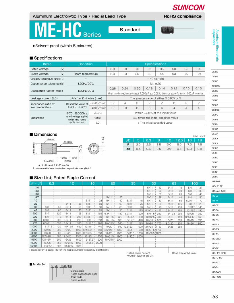
63
Rated ripple current�mArms(120Hz, 85℃)�
Case size:φDxL(mm)
ME-HCSeriesStandard
●Solvent proof (within 5 minutes)
■ Model No.
φD 5 6.3 8 10 12.5 16 18F�
φd
2.0�
0.5
2.5�
0.5
3.5�
0.6
5.0�
0.6
5.0�
0.6
7.5�
0.8
7.5�
0.8
6 ME 15000 HC
Series code�Rated capacitance code�Type code�Rated voltage
Aluminum Electrolytic Type / Radial Lead Type RoHS compliance
■ Specifications
■ Dimensions
■ Size List, Rated Ripple Current
Endurance
85℃, 2,000hrs.�rated voltage applied(With the rated�ripple current)
Impedance ratio at�low temperature
Based the value at�120Hz, +20℃�
△C/C�
tanδ�
LC
-25℃�
-40℃�
Z/Z20℃�
Z/Z20℃�
�
-40 to +85�
M : ±20�
�
When rated capacitance exceeds 1,000μF, add 0.02 to the value above for each 1,000μF increase.�
The greater value of either 0.01CV or 3�
�
6.3�
8.0�
�
�
0.28�
�
�
5�
12
10�
13�
�
�
0.24�
�
�
4�
10
16�
20�
�
�
0.20�
�
�
3�
8
25�
32�
�
�
0.16�
�
�
2�
6
35�
44�
�
�
0.14�
�
�
2�
4
50�
63�
�
�
0.12�
�
�
2�
4
63�
79�
�
�
0.10�
�
�
2�
4
100�
125�
�
�
0.10�
�
�
2�
4
SpecificationsConditionItems
Rated voltage�
Surge voltage�
Category temperature range�
Capacitance tolerance�
Dissipation Factor(tanδ)��
Leakage current(LC)�
(V)�
(V)�
(℃)�
(%)
-�
Room temperature�
-�
120Hz/20℃�
120Hz/20℃�
�
μA/after 2minutes (max)
Within ±25% of the initial value�
≤ 2 times the initial specified value�
≤ The initial specified value
(Unit : mm)
1.0�2.2�3.3�4.7�10�22�33�47�100�220�330�470�1000�2200�3300�4700�6800�10000�15000
������
5×11�5×11�5×11�5×11�
6.3×11�6.3×11�8×11.5�10×16�10×20�
12.5×20�12.5×25�16×25�16×35.5
������
50�60�120�210�260�330�420�890�1080�1400�1600�1750�1900
�����
5×11�5×11�5×11�5×11�5×11�
6.3×11�6.3×11�10×12.5�10×20�
12.5×20�12.5×25�16×25�16×31.5�18×35.5
�����
38�58�70�125�210�295�330�620�1000�1300�1550�1800�1900�2000
����
5×11�5×11�5×11�5×11�5×11�
6.3×11�8×11.5�8×11.5�10×16�
12.5×20�12.5×25�16×25�16×31.5�18×35.5
����
28�50�60�85�165�260�360�380�740�1150�1500�1750�1900�2000
���
5×11�5×11�5×11�5×11�5×11�
6.3×11�8×11.5�8×11.5�10×12.5�10×20�
12.5×25�16×25�16×31.5�18×35.5
���
25�40�60�80�90�180�320�380�540�940�1350�1600�1900�2000
����
5×11�5×11�5×11�5×11�
6.3×11�8×11.5�10×12.5�10×16�
12.5×20�16×25�16×35.5�18×35.5
����
45�75�90�125�200�320�440�585�1000�1500�1750�2000
5×11�5×11�5×11�5×11�5×11�5×11�5×11�
6.3×11�8×11.5�10×12.5�10×16�10×20�
12.5×25�16×31.5�18×35.5
10�20�28�38�50�90�110�135�250�410�580�750�1150�1700�1850
5×11�5×11�5×11�5×11�5×11�5×11�
6.3×11�6.3×11�8×12.5�10×16�10×20�
12.5×20�16×25
10�20�28�40�60�105�130�160�280�450�600�800�1250
5×11�5×11�5×11�5×11�
6.3×11�8×11.5�8×12.5�10×12.5�10×20�
12.5×25�16×25�16×30
21�30�40�50�70�120�145�180�350�550�750�950
μFV
Please refer to page 15 for the ripple current frequency coefficient.
6.3 10 16 25 35 50 63 100
A pressure relief vent is attached to products over φD=6.3α : L<20 α=1.5, L≥20 α=2.0
φd±0.05 F±0.5sleeve
L+αmax15min20min
5min
φD+0.5max
Alu
min
um
Electro
lytic C
apacito
rs
CE-BJ�
CE-BE�
CE-BD�
CE-BSS�
CE-BS�
CE-FE�
CE-FD�
CE-LD�
CE-FSS�
CE-FU�
CE-FS�
CE-FH�
CE-GA�
CE-AX�
CE-KX�
CE-LX�
CE-LS�
CE-LH�
CE-LL�
CE-PC�
CE-PH�
CE-NP�
CE-FN�
ME-SWB�
ME-UZ・SZ�
ME-UAX・SAX�
ME-LS�
ME-HC�
ME-CZ�
ME-CA�
ME-CX�
ME-AX�
ME-WX�
ME-WA�
ME-WL�
ME-SWG�
ME-WG�
ME-PX�
ME-HPC・HPD�
ME-FC・FD�
ME-FAZ�
ME-FH�
ME-SWN�
ME-HWN
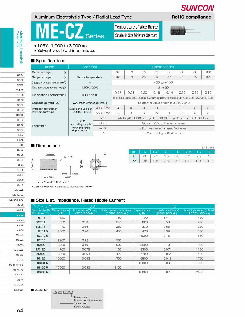
V 6.3Rated ripple current(mArms)�(105℃/100kHz)
Capacitance�(μF)
Items Impedance(Ωmax)�(20℃/100kHz)
10Rated ripple current(mArms)�(105℃/100kHz)
Capacitance�(μF)
Impedance(Ωmax)�(20℃/100kHz)
Case size�φDxL(mm)
64
●105℃, 1,000 to 3,000hrs.� ●Solvent proof (within 5 minutes)
ME-CZ Series
Temperature of Wide Range
Smaller in Size Miniature Standard
■ Dimensions
■ Specifications
■ Size List, Impedance, Rated Ripple Current
5×11 �
6.3×11 �
6.3×11 �
8×11.5�
10×12.5�
10×16 �
10×20 �
12.5×20 �
12.5×25 �
16×25 �
16×31.5�
16×35.5�
18×35.5
220�
330�
470�
1000�
�
2200�
3300�
4700�
6800�
10000�
�
15000
1.4 �
0.58 �
0.55 �
0.26 �
�
0.12 �
0.10 �
0.072�
0.054�
0.043�
�
0.032
160�
240�
250�
450�
�
760�
900�
1100�
1420�
1700�
�
2100
100�
220�
330�
470�
1000�
�
2200�
3300�
4700�
6800�
10000�
�
15000
1.4 �
0.58 �
0.55 �
0.39 �
0.16 �
�
0.10 �
0.074�
0.054�
0.043�
0.035�
�
0.028
150�
240�
250�
370�
560�
�
900�
1100�
1420�
1700�
1950�
�
2400
φD 5 6.3 8 10 12.5 16 18F�
φd
2.0�
0.5
2.5�
0.5
3.5�
0.6
5.0�
0.6
5.0�
0.6
7.5�
0.8
7.5�
0.8
(Unit : mm)
■ Model No.16 ME 100 CZ
Series code�Rated capacitance code�Type code�Rated voltage
Aluminum Electrolytic Type / Radial Lead Type RoHS compliance
Endurance
105℃�rated voltage applied(With the rated�ripple current)
Impedance ratio at�low temperature
Based the value at�120Hz, +20℃�
Test�
△C/C�
tanδ�
LC
ー40℃�
ー55℃�
Z20℃�
Z20℃�
�
-55 to +105�
M : ±20�
�
When rated capacitance exceeds 1,000μF, add 0.02 to the value above for each 1,000μF increase.�
The greater value of either 0.01CV or 3�
�
�
6.3�
8.0�
�
�
0.28�
�
�
4�
10
10�
13�
�
�
0.24�
�
�
4�
8
16�
20�
�
�
0.20�
�
�
3�
6
25�
32�
�
�
0.16�
�
�
3�
5
35�
44�
�
�
0.14�
�
�
2�
4
50�
63�
�
�
0.12�
�
�
2�
3
63�
79�
�
�
0.10�
�
�
2�
3
100�
125�
�
�
0.10�
�
�
2�
3
SpecificationsConditionItems
Rated voltage�
Surge voltage�
Category temperature range�
Capacitance tolerance�
Dissipation Factor(tanδ)�
�Leakage current(LC)�
(V)�
(V)�
(℃)�
(%)
-�
Room temperature�
-�
120Hz/20℃�
120Hz/20℃�
�
μA/after 2minutes (max)
φ5 to φ8 : 1,000hrs., φ10 : 2,000hrs., φ12.5 to φ18 : 3,000hrs.�
Within ±25% of the initial value�
≤ 2 times the initial specified value�
≤ The initial specified value
α: L<20 α=1.5, L≥20 α=2.0
φd±0.05 F±0.5sleeve
L+αmax15min20min
5min
φD+0.5max
A pressure relief vent is attached to products over φD=6.3
Alu
min
um
Electro
lytic C
apacito
rs
CE-BJ�
CE-BE�
CE-BD�
CE-BSS�
CE-BS�
CE-FE�
CE-FD�
CE-LD�
CE-FSS�
CE-FU�
CE-FS�
CE-FH�
CE-GA�
CE-AX�
CE-KX�
CE-LX�
CE-LS�
CE-LH�
CE-LL�
CE-PC�
CE-PH�
CE-NP�
CE-FN�
ME-SWB�
ME-UZ・SZ�
ME-UAX・SAX�
ME-LS�
ME-HC�
ME-CZ�
ME-CA�
ME-CX�
ME-AX�
ME-WX�
ME-WA�
ME-WL�
ME-SWG�
ME-WG�
ME-PX�
ME-HPC・HPD�
ME-FC・FD�
ME-FAZ�
ME-FH�
ME-SWN�
ME-HWN
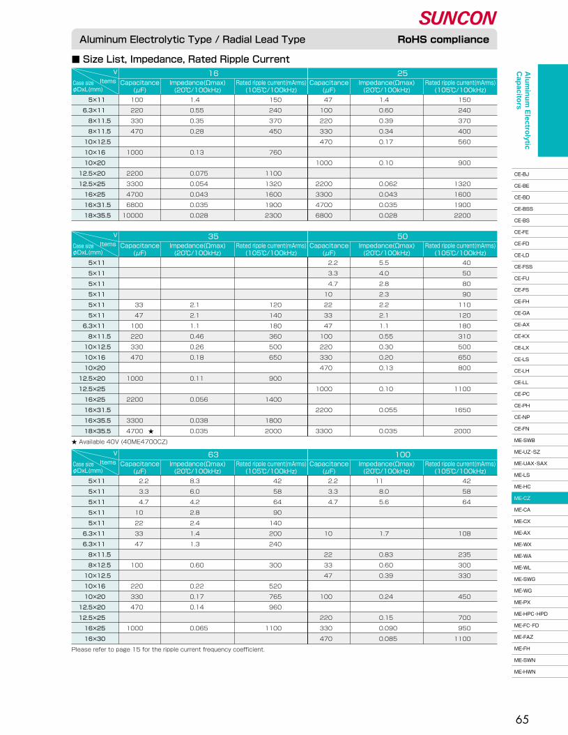
V 16Rated ripple current(mArms)�(105℃/100kHz)
Capacitance�(μF)
Items Impedance(Ωmax)�(20℃/100kHz)
25Rated ripple current(mArms)�(105℃/100kHz)
Capacitance�(μF)
Impedance(Ωmax)�(20℃/100kHz)
Case size�φDxL(mm)
V 35Rated ripple current(mArms)�(105℃/100kHz)
Capacitance�(μF)
Items Impedance(Ωmax)�(20℃/100kHz)
50Rated ripple current(mArms)�(105℃/100kHz)
Capacitance�(μF)
Impedance(Ωmax)�(20℃/100kHz)
Case size�φDxL(mm)
V 63Rated ripple current(mArms)�(105℃/100kHz)
Capacitance�(μF)
Items Impedance(Ωmax)�(20℃/100kHz)
100Rated ripple current(mArms)�(105℃/100kHz)
Capacitance�(μF)
Impedance(Ωmax)�(20℃/100kHz)
Case size�φDxL(mm)
65
■ Size List, Impedance, Rated Ripple Current
5×11 �
6.3×11 �
8×11.5�
8×11.5�
10×12.5�
10×16 �
10×20 �
12.5×20 �
12.5×25 �
16×25 �
16×31.5�
18×35.5
100 �
220 �
330 �
470 �
�
1000 �
�
2200 �
3300 �
4700 �
6800 �
10000 �
1.4 �
0.55 �
0.35 �
0.28 �
�
0.13 �
�
0.075�
0.054�
0.043�
0.035�
0.028
150�
240�
370�
450�
�
760�
�
1100�
1320�
1600�
1900�
2300
47 �
100 �
220 �
330 �
470 �
�
1000 �
�
2200 �
3300 �
4700 �
6800 �
1.4 �
0.60 �
0.39 �
0.34 �
0.17 �
�
0.10 �
�
0.062�
0.043�
0.035�
0.028
150�
240�
370�
400�
560�
�
900�
�
1320�
1600�
1900�
2200
Please refer to page 15 for the ripple current frequency coefficient.
5×11 �
5×11 �
5×11 �
5×11 �
5×11 �
5×11 �
6.3×11 �
8×11.5�
10×12.5�
10×16 �
10×20 �
12.5×20 �
12.5×25 �
16×25 �
16×31.5�
16×35.5�
18×35.5
�
�
�
�
33 �
47 �
100 �
220 �
330 �
470 �
�
1000 �
�
2200 �
�
3300 �
4700 �
�
�
�
�
2.1 �
2.1 �
1.1 �
0.46 �
0.26 �
0.18 �
�
0.11 �
�
0.056�
�
0.038�
0.035
�
�
�
�
120�
140�
180�
360�
500�
650�
�
900�
�
1400�
�
1800�
2000
2.2 �
3.3 �
4.7 �
10 �
22 �
33 �
47 �
100 �
220 �
330 �
470 �
�
1000 �
�
2200 �
�
3300 �
5.5 �
4.0 �
2.8 �
2.3 �
2.2 �
2.1 �
1.1 �
0.55 �
0.30 �
0.20 �
0.13 �
�
0.10 �
�
0.055�
�
0.035
40�
50�
80�
90�
110�
120�
180�
310�
500�
650�
800�
�
1100�
�
1650�
�
2000
★ Available 40V (40ME4700CZ)
5×11 �
5×11 �
5×11 �
5×11 �
5×11 �
6.3×11 �
6.3×11 �
8×11.5�
8×12.5�
10×12.5�
10×16 �
10×20 �
12.5×20 �
12.5×25 �
16×25 �
16×30 �
2.2 �
3.3 �
4.7 �
10 �
22 �
33 �
47 �
�
100 �
�
220 �
330 �
470 �
�
1000 �
8.3 �
6.0 �
4.2 �
2.8 �
2.4 �
1.4 �
1.3 �
�
0.60 �
�
0.22 �
0.17 �
0.14 �
�
0.065
42�
58�
64�
90�
140�
200�
240�
�
300�
�
520�
765�
960�
�
1100
2.2 �
3.3 �
4.7 �
�
�
10 �
�
22 �
33 �
47 �
�
100 �
�
220 �
330 �
470 �
11 �
8.0 �
5.6 �
�
�
1.7 �
�
0.83 �
0.60 �
0.39 �
�
0.24 �
�
0.15 �
0.090�
0.085
42�
58�
64�
�
�
108�
�
235�
300�
330�
�
450�
�
700�
950�
1100
Aluminum Electrolytic Type / Radial Lead Type RoHS compliance
★�
Alu
min
um
Electro
lytic C
apacito
rs
CE-BJ�
CE-BE�
CE-BD�
CE-BSS�
CE-BS�
CE-FE�
CE-FD�
CE-LD�
CE-FSS�
CE-FU�
CE-FS�
CE-FH�
CE-GA�
CE-AX�
CE-KX�
CE-LX�
CE-LS�
CE-LH�
CE-LL�
CE-PC�
CE-PH�
CE-NP�
CE-FN�
ME-SWB�
ME-UZ・SZ�
ME-UAX・SAX�
ME-LS�
ME-HC�
ME-CZ�
ME-CA�
ME-CX�
ME-AX�
ME-WX�
ME-WA�
ME-WL�
ME-SWG�
ME-WG�
ME-PX�
ME-HPC・HPD�
ME-FC・FD�
ME-FAZ�
ME-FH�
ME-SWN�
ME-HWN

V 6.3
Rated ripple current(mArms)�(105℃/10k to 200kHz)
Capacitance�(μF)
ItemsImpedance(Ωmax)�(20℃/100kHz)
10
Rated ripple current(mArms)�(105℃/10k to 200kHz)
Capacitance�(μF)
Impedance(Ωmax)�(20℃/100kHz)
Case size�φDxL(mm)
66
●105℃, 1,000 to 3,000hrs.� ●Solvent proof (within 5 minutes)
ME-CA Series
Low Impedance
Miniature
■ Dimensions
■ Specifications
φD 16F�
φd
7.5�
0.8
5.0�
0.6
5.0�
0.6
3.5�
0.6
2.5�
0.5
2.0�
0.5
12.51086.35
(Unit : mm)
■ Size List, Impedance, Rated Ripple Current
5×11 �
6.3×11 �
6.3×11 �
8×11.5�
10×12.5�
10×16 �
10×20 �
12.5×20 �
12.5×25 �
16×25 �
16×31.5�
16×35.5
220�
330�
470�
1000�
�
2200�
3300�
4700�
6800�
10000�
�
15000
0.50�
0.30�
0.24�
0.15�
�
0.066�
0.047�
0.042�
0.031�
0.026�
�
0.022
180�
280�
280�
560�
�
950�
1150�
1460�
1780�
2000�
�
2200
�
220�
330�
470�
1000�
�
2200�
3300�
4700�
6800�
10000
�
0.30�
0.24�
0.16�
0.086�
�
0.047�
0.042�
0.031�
0.026�
0.022
�
280�
280�
410�
710�
�
1150�
1460�
1780�
2000�
2200
Aluminum Electrolytic Type / Radial Lead Type RoHS compliance
Endurance
105℃�rated voltage applied(With the rated�ripple current)
Impedance ratio at�low temperature
Based the value at�120Hz, +20℃�
Test�
△C/C�
tanδ�
LC
ー40℃�
ー55℃�
Z/Z20℃�
Z/Z20℃�
�
-55 to +105�
M : ±20�
�
When rated capacitance exceeds 1,000μF, add 0.02 to the value above for each 1,000μF increase.�
The greater value of either 0.01CV or 3�
�
�
6.3�
8.0�
�
�
0.28�
�
�
3�
6
10�
13�
�
�
0.24�
�
�
3�
5
16�
20�
�
�
0.20�
�
�
2�
4
25�
32�
�
�
0.16�
�
�
2�
4
35�
44�
�
�
0.14�
�
�
2�
3
50�
63�
�
�
0.12�
�
�
2�
3
SpecificationsConditionItems
Rated voltage�
Surge voltage�
Category temperature range�
Capacitance tolerance�
Dissipation Factor(tanδ)��
Leakage current(LC)�
(V)�
(V)�
(℃)�
(%)
-�
Room temperature�
-�
120Hz/20℃�
120Hz/20℃�
�
μA/after 2minutes (max)
φ5 to φ8 : 1,000hrs., φ10 : 2,000hrs., φ12.5 to φ16 : 3,000hrs.�
Within ±25% of the initial value�
≤ 2 times the initial specified value�
≤ The initial specified value
α : L<20 α=1.5, L≥20 α=2.0
φd±0.05 F±0.5sleeve
L+αmax15min20min
5min
φD+0.5max
A pressure relief vent is attached to products over φD=6.3
Alu
min
um
Electro
lytic C
apacito
rs
CE-BJ�
CE-BE�
CE-BD�
CE-BSS�
CE-BS�
CE-FE�
CE-FD�
CE-LD�
CE-FSS�
CE-FU�
CE-FS�
CE-FH�
CE-GA�
CE-AX�
CE-KX�
CE-LX�
CE-LS�
CE-LH�
CE-LL�
CE-PC�
CE-PH�
CE-NP�
CE-FN�
ME-SWB�
ME-UZ・SZ�
ME-UAX・SAX�
ME-LS�
ME-HC�
ME-CZ�
ME-CA�
ME-CX�
ME-AX�
ME-WX�
ME-WA�
ME-WL�
ME-SWG�
ME-WG�
ME-PX�
ME-HPC・HPD�
ME-FC・FD�
ME-FAZ�
ME-FH�
ME-SWN�
ME-HWN
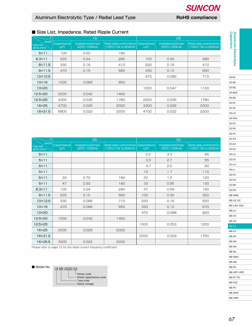
V 16
Rated ripple current(mArms)�(105℃/10k to 200kHz)
Capacitance�(μF)
ItemsImpedance(Ωmax)�(20℃/100kHz)
25
Rated ripple current(mArms)�(105℃/10k to 200kHz)
Capacitance�(μF)
Impedance(Ωmax)�(20℃/100kHz)
Case size�φDxL(mm)
V 35
Rated ripple current(mArms)�(105℃/10k to 200kHz)
Capacitance�(μF)
ItemsImpedance(Ωmax)�(20℃/100kHz)
50
Rated ripple current(mArms)�(105℃/10k to 200kHz)
Capacitance�(μF)
Impedance(Ωmax)�(20℃/100kHz)
Case size�φDxL(mm)
67
■ Size List, Impedance, Rated Ripple Current
■ Model No.16 ME 2200 CA
Series code�Rated capacitance code�Type code�Rated voltage
5×11 �
6.3×11 �
8×11.5�
8×11.5�
10×12.5�
10×16 �
10×20 �
12.5×20 �
12.5×25 �
16×25 �
16×31.5
100�
220�
330�
470�
�
1000�
�
2200�
3300�
4700�
6800
0.50�
0.24�
0.16�
0.15�
�
0.066�
�
0.042�
0.035�
0.026�
0.022
180�
280�
410�
560�
�
950�
�
1460�
1780�
2000�
2200
�
100�
220�
330�
470�
�
1000�
�
2200�
3300�
4700
�
0.30�
0.16�
0.15�
0.086�
�
0.047�
�
0.035�
0.026�
0.022
�
280�
410�
560�
710�
�
1150�
�
1780�
2000�
2200
5×11 �
5×11 �
5×11 �
5×11 �
5×11 �
5×11 �
6.3×11 �
8×11.5�
10×12.5�
10×16 �
10×20 �
12.5×20 �
12.5×25 �
16×25 �
16×31.5�
16×35.5
�
�
�
�
33�
47�
100�
220�
330�
470�
�
1000�
�
2200�
�
3300
�
�
�
�
0.72�
0.50�
0.24�
0.15�
0.086�
0.066�
�
0.042�
�
0.026�
�
0.022
�
�
�
�
180�
180�
280�
560�
710�
950�
�
1460�
�
2000�
�
2200
2.2 �
3.3 �
4.7 �
10 �
22 �
33 �
47 �
100 �
220 �
330 �
470 �
�
1000 �
�
2200 �
3.0�
2.7�
2.0�
1.7�
1.2�
0.95�
0.56�
0.30�
0.16�
0.12�
0.088�
�
0.053�
�
0.029
45�
55�
90�
110�
120�
130�
190�
320�
520�
670�
820�
�
1200�
�
1750
Please refer to page 15 for the ripple current frequency coefficient.
Aluminum Electrolytic Type / Radial Lead Type RoHS complianceA
lum
inu
m E
lectrolytic
Cap
acitors
CE-BJ�
CE-BE�
CE-BD�
CE-BSS�
CE-BS�
CE-FE�
CE-FD�
CE-LD�
CE-FSS�
CE-FU�
CE-FS�
CE-FH�
CE-GA�
CE-AX�
CE-KX�
CE-LX�
CE-LS�
CE-LH�
CE-LL�
CE-PC�
CE-PH�
CE-NP�
CE-FN�
ME-SWB�
ME-UZ・SZ�
ME-UAX・SAX�
ME-LS�
ME-HC�
ME-CZ�
ME-CA�
ME-CX�
ME-AX�
ME-WX�
ME-WA�
ME-WL�
ME-SWG�
ME-WG�
ME-PX�
ME-HPC・HPD�
ME-FC・FD�
ME-FAZ�
ME-FH�
ME-SWN�
ME-HWN

V 6.3Rated ripple current(mArms)�(105℃/10k to 200kHz)
Capacitance�(μF)
Items Impedance(Ωmax)�(20℃/100kHz)
10Rated ripple current(mArms)�(105℃/10k to 200kHz)
Capacitance�(μF)
Impedance(Ωmax)�(20℃/100kHz)
Case size�φDxL(mm)
68
●105℃, 2,000 to 7,000hrs.� ●Solvent proof (within 5 minutes)
ME-CX Series
Low Impedance
Miniature, Long Life
■ Dimensions
■ Specifications
■ Size List, Impedance, Rated Ripple Current
φD 5 6.3 8 10 12.5 16 18F�
φd
2.0�
0.5
2.5�
0.5
3.5�
0.6
5.0�
0.6
5.0�
0.6★�
7.5�
0.8
7.5�
0.8
(Unit : mm)
★φ12.5×30:φd=0.8
5×11 �
6.3×11 �
6.3×11 �
8×11.5�
8×11.5�
8×15 �
8×20 �
8×20 �
10×12.5�
10×16 �
10×16 �
10×20 �
10×22 �
12.5×20 �
12.5×25 �
12.5×25 �
12.5×30 �
16×21 �
16×25 �
16×25 �
16×31.5�
16×31.5�
16×35.5�
18×21 �
18×25 �
18×30.5�
18×35.5
180�
330�
390�
680�
�
1000�
1200�
1500�
1200�
1500�
�
2200�
2700�
3900�
4700�
5600�
6800�
5600�
6800�
8200�
10000�
�
12000�
6800�
10000�
12000�
15000
★1�
★1�
�
�
�
�
�
�
�
�
★1�
★2�
�
�
�
�
�
★2�
★2�
★2
★1�
�
�
�
�
�
�
�
�
�
★1�
★2�
�
�
�
�
�
★2�
★2�
★2
0.34�
0.17�
0.17�
0.11�
�
0.080�
0.060�
0.060�
0.063�
0.049�
�
0.036�
0.036�
0.035�
0.027�
0.027�
0.024�
0.032�
0.022�
0.022�
0.017�
�
0.016�
0.030�
0.022�
0.017�
0.016
205�
330�
330�
580�
�
750�
1000�
1000�
900�
1200�
�
1450�
1500�
1660�
2000�
2000�
2450�
2000�
2560�
2560�
3010�
�
3150�
2490�
2740�
3330�
3680
150�
270�
330�
470�
560�
680�
1000�
�
820�
1000�
1200�
1500�
1800�
2700�
3900�
�
4700�
3900�
4700�
5600�
6800�
8200�
10000�
5600�
6800�
10000�
12000
0.34�
0.17�
0.17�
0.11�
0.11�
0.080�
0.060�
�
0.063�
0.049�
0.049�
0.036�
0.036�
0.035�
0.027�
�
0.024�
0.032�
0.022�
0.022�
0.017�
0.017�
0.016�
0.030�
0.022�
0.017�
0.016
205�
330�
330�
580�
580�
750�
1000�
�
900�
1200�
1200�
1450�
1500�
1660�
2000�
�
2450�
2000�
2560�
2560�
3010�
3010�
3150�
2490�
2740�
3330�
3680
Please refer to page 15 for the ripple current frequency coefficient. ★1 CXL series ★2 CXS series
Aluminum Electrolytic Type / Radial Lead Type RoHS compliance
Endurance
105℃�rated voltage applied(With the rated�ripple current)
Impedance ratio at�low temperature
Based the value at�120Hz, +20℃�
Test�
△C/C�
tanδ�
LC
ー40℃�
ー55℃�
Z/Z20℃�
Z/Z20℃�
16�
20�
-55 to +105�
M : ±20�
0.16�
When rated capacitance exceeds 1.000μF, add 0.02 to the value above for each 1,000μF increase.�
0.01CV�
2�
3
6.3�
8.0�
�
�
0.22�
�
�
3�
4
10�
13�
�
�
0.19�
�
�
2�
4
25�
32�
�
�
0.14�
�
�
2�
3
35�
44�
�
�
0.12�
�
�
2�
3
SpecificationsConditionItemsRated voltage�
Surge voltage�
Category temperature range�
Capacitance tolerance�
Dissipation Factor(tanδ)�
�Leakage current(LC)�
(V)�
(V)�
(℃)�
(%)
-�
Room temperature�
-�
120Hz/20℃�
120Hz/20℃��
μA/after 2minutes (max)
φ5 to φ6.3 : 2,000hrs., φ8 : 3,000hrs., φ10 : 4,000hrs., φ12.5 : 5,000hrs., φ16 to φ18 : 7,000hrs.�
Within ±25% of the initial value�
≤ 2 times the initial specified value�≤ The initial specified value
α: L<20 α=1.5, L≥20 α=2.0
φd±0.05 F±0.5sleeve
L+αmax15min20min
5min
φD+0.5max
A pressure relief vent is attached to products over φD=6.3
Alu
min
um
Electro
lytic C
apacito
rs
CE-BJ�
CE-BE�
CE-BD�
CE-BSS�
CE-BS�
CE-FE�
CE-FD�
CE-LD�
CE-FSS�
CE-FU�
CE-FS�
CE-FH�
CE-GA�
CE-AX�
CE-KX�
CE-LX�
CE-LS�
CE-LH�
CE-LL�
CE-PC�
CE-PH�
CE-NP�
CE-FN�
ME-SWB�
ME-UZ・SZ�
ME-UAX・SAX�
ME-LS�
ME-HC�
ME-CZ�
ME-CA�
ME-CX�
ME-AX�
ME-WX�
ME-WA�
ME-WL�
ME-SWG�
ME-WG�
ME-PX�
ME-HPC・HPD�
ME-FC・FD�
ME-FAZ�
ME-FH�
ME-SWN�
ME-HWN
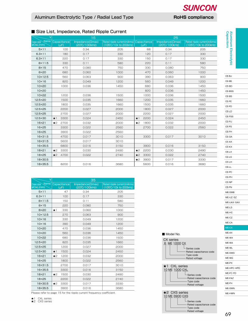
V 35Rated ripple current(mArms)�(105℃/10k to 200kHz)
Capacitance�(μF)
Items Impedance(Ωmax)�(20℃/100kHz)
Case size�φDxL(mm)
V 16Rated ripple current(mArms)�(105℃/10k to 200kHz)
Capacitance�(μF)
Items Impedance(Ωmax)�(20℃/100kHz)
25Rated ripple current(mArms)�(105℃/10k to 200kHz)
Capacitance�(μF)
Impedance(Ωmax)�(20℃/100kHz)
Case size�φDxL(mm)
69
■ Model No.
10 ME 1000 CXL
Series code�Rated capacitance code�Type code�Rated voltage
6 ME 1000 CX
Series code�Rated capacitance code�Type code�Rated voltage
10 ME 3900 CXS
★1 CXL series
CX series
★2 CXS series
Series code�Rated capacitance code�Type code�Rated voltage
�
�
�
�
�
�
�
�
�
�
�
�
�
�
�
★1�
★2�
�
�
�
�
�
★2�
★2
�
�
�
�
★1�
�
�
�
�
�
�
�
�
★1�
★2�
�
�
�
★2�
�
★2
�
�
�
�
�
�
�
�
�
�
�
�
�
�
�
★1�
★2�
�
�
�
�
�
★2�
★2�
★2
■ Size List, Impedance, Rated Ripple Current
5×11 �
6.3×11 �
6.3×11 �
8×11.5�
8×15 �
8×20 �
10×12.5�
10×16 �
10×20 �
10×20 �
10×22 �
12.5×20 �
12.5×20 �
12.5×25 �
12.5×25 �
12.5×30 �
16×21 �
16×25 �
16×25 �
16×31.5�
16×31.5�
16×35.5�
18×21 �
18×25 �
18×30.5�
18×35.5
100�
180�
220�
330�
470�
680�
560�
820�
1000�
�
1200�
1500�
1800�
2200�
2700�
3300�
2700�
3300�
3900�
4700�
5600�
6800�
3300�
4700�
�
8200
0.34�
0.17�
0.17�
0.11�
0.080�
0.060�
0.063�
0.049�
0.036�
�
0.036�
0.035�
0.035�
0.027�
0.027�
0.024�
0.032�
0.022�
0.022�
0.017�
0.017�
0.016�
0.030�
0.022�
�
0.016
205�
330�
330�
580�
750�
1000�
900�
1200�
1450�
�
1500�
1660�
1660�
2000�
2000�
2450�
2000�
2560�
2560�
3010�
3010�
3150�
2490�
2740�
�
3680
68�
120�
150�
220�
330�
470�
390�
560�
680�
820�
1000�
1200�
1500�
1800�
2200�
2200�
1800�
2700�
�
3300�
�
3900�
2200�
3300�
3900�
5600
0.34�
0.17�
0.17�
0.11�
0.080�
0.060�
0.063�
0.049�
0.036�
0.036�
0.036�
0.035�
0.035�
0.027�
0.027�
0.024�
0.032�
0.022�
�
0.017�
�
0.016�
0.030�
0.022�
0.017�
0.016
205�
330�
330�
580�
750�
1000�
900�
1200�
1450�
1450�
1500�
1660�
1660�
2000�
2000�
2450�
2000�
2560�
�
3010�
�
3150�
2490�
2740�
3330�
3680
5×11 �
6.3×11 �
8×11.5�
8×15 �
8×20 �
10×12.5�
10×16 �
10×16 �
10×20 �
10×20 �
10×22 �
12.5×20 �
12.5×25 �
12.5×30 �
16×21 �
16×25 �
16×31.5�
16×35.5�
18×21 �
18×25 �
18×30.5�
18×35.5
47�
100�
150�
220�
330�
270�
330�
390�
470�
560�
680�
820�
1200�
1500�
1200�
1800�
2700�
3300�
1500�
2200�
3300�
3900
0.34�
0.17�
0.11�
0.080�
0.060�
0.063�
0.049�
0.049�
0.036�
0.036�
0.036�
0.035�
0.027�
0.024�
0.032�
0.022�
0.017�
0.016�
0.030�
0.022�
0.017�
0.016
205�
330�
580�
750�
1000�
900�
1200�
1200�
1450�
1450�
1500�
1660�
2000�
2450�
2000�
2560�
3010�
3150�
2490�
2740�
3330�
3680
Please refer to page 15 for the ripple current frequency coefficient.��★1 CXL series�★2 CXS series
Aluminum Electrolytic Type / Radial Lead Type RoHS complianceA
lum
inu
m E
lectrolytic
Cap
acitors
CE-BJ�
CE-BE�
CE-BD�
CE-BSS�
CE-BS�
CE-FE�
CE-FD�
CE-LD�
CE-FSS�
CE-FU�
CE-FS�
CE-FH�
CE-GA�
CE-AX�
CE-KX�
CE-LX�
CE-LS�
CE-LH�
CE-LL�
CE-PC�
CE-PH�
CE-NP�
CE-FN�
ME-SWB�
ME-UZ・SZ�
ME-UAX・SAX�
ME-LS�
ME-HC�
ME-CZ�
ME-CA�
ME-CX�
ME-AX�
ME-WX�
ME-WA�
ME-WL�
ME-SWG�
ME-WG�
ME-PX�
ME-HPC・HPD�
ME-FC・FD�
ME-FAZ�
ME-FH�
ME-SWN�
ME-HWN

V 6.3Rated ripple current(mArms)�(105℃/10k to 200kHz)
Capacitance�(μF)
Items Impedance(Ωmax)�(20℃/100kHz)
10Rated ripple current(mArms)�(105℃/10k to 200kHz)
Capacitance�(μF)
Impedance(Ωmax)�(20℃/100kHz)
Case size�φDxL(mm)
70
●105℃, 2,500 to 10,000hrs.� ●Solvent proof (within 5 minutes)
ME-AX Series
■ Dimensions
■ Specifications
Low Impedance
Long Life
φD 5 6.3 8 10 12.5 16 18F�
φd
2.0�
0.5
2.5�
0.5
3.5�
0.6
5.0�
0.6
5.0�
0.6
7.5�
0.8
7.5�
0.8
(Unit : mm)
■ Size List, Impedance, Rated Ripple Current
5×11 �
6.3×11 �
8×11.5�
8×12.5�
8×15 �
8×20 �
10×12.5�
10×16 �
10×20 �
10×22 �
12.5×20 �
12.5×25 �
16×25 �
16×31.5�
16×35 �
18×35.5
150�
270�
470�
560�
680�
1000�
820�
1200�
1500�
1800�
2700�
3900�
5600�
8200�
10000�
12000
★1
0.42�
0.22�
0.11�
0.11�
0.085�
0.069�
0.085�
0.062�
0.044�
0.039�
0.038�
0.029�
0.022�
0.018�
0.018�
0.018
190�
300�
560�
570�
730�
800�
800�
1050�
1250�
1450�
1600�
1800�
2100�
2350�
2550�
2800
100�
220�
330�
390�
470�
680�
680�
820�
1200�
1500�
2200�
2700�
3900�
5600�
6800�
8200
0.42�
0.22�
0.11�
0.11�
0.085�
0.069�
0.085�
0.062�
0.044�
0.039�
0.038�
0.029�
0.022�
0.018�
0.018�
0.018
190�
300�
560�
570�
730�
800�
800�
1050�
1250�
1450�
1600�
1800�
2100�
2350�
2550�
2800
■ Model No.
16 ME 470 AXL
Series code�Rated capacitance code�Type code�Rated voltage
10 ME 470 AX
Series code�Rated capacitance code�Type code�Rated voltage
★1 AXL seriesAX series
★1 AXL series
Aluminum Electrolytic Type / Radial Lead Type RoHS compliance
Please refer to page 15 for the ripple current frequency coefficient.
Endurance
105℃�rated voltage applied(With the rated�ripple current)
Impedance ratio at�low temperature
Based the value at�120Hz, +20℃�
Test�
�
△C/C�
tanδ�
LC
ー40℃�
ー55℃�
Z/Z20℃�
Z/Z20℃�
�
-55 to +105�
M : ±20�
�
When rated capacitance exceeds 1,000μF, add 0.02 to the value above for each 1,000μF increase.�
The greater value of either 0.01CV or 3�
�
�
6.3�
8.0�
�
�
0.22�
�
�
3�
4
10�
13�
�
�
0.19�
�
�
2�
4
16�
20�
�
�
0.16�
�
�
2�
3
25�
32�
�
�
0.14�
�
�
2�
3
35�
44�
�
�
0.12�
�
�
2�
3
50�
63�
�
�
0.10�
�
�
2�
2
63�
79�
�
�
0.10�
�
�
2�
2
100�
125�
-40 to +105�
�
0.10�
�
�
2�
-�
SpecificationsConditionItems
Rated voltage�
Surge voltage�
Category temperature range�
Capacitance tolerance�
Dissipation Factor(tanδ)��
Leakage current(LC)�
(V)�
(V)�
(℃)�
(%)
-�
Room temperature�
-�
120Hz/20℃�
120Hz/20℃��
μA/after 2minutes (max)
φ5 : 2,500hrs., φ6.3 : 3,000hrs., φ8×11.5, φ8×12.5 : 3,500hrs.,�φ8×15, φ8×20 : 4,500hrs., φ10 : 5,000hrs., φ12.5 : 7,000hrs., φ16 to φ18 : 10,000hrs.
Within ±20% of the initial value�
≤ 2 times the initial specified value�
≤ The initial specified value
α : L<20 α=1.5, L≥20 α=2.0
φd±0.05 F±0.5sleeve
L+αmax15min20min
5min
φD+0.5max
A pressure relief vent is attached to products over φD=6.3
Alu
min
um
Electro
lytic C
apacito
rs
CE-BJ�
CE-BE�
CE-BD�
CE-BSS�
CE-BS�
CE-FE�
CE-FD�
CE-LD�
CE-FSS�
CE-FU�
CE-FS�
CE-FH�
CE-GA�
CE-AX�
CE-KX�
CE-LX�
CE-LS�
CE-LH�
CE-LL�
CE-PC�
CE-PH�
CE-NP�
CE-FN�
ME-SWB�
ME-UZ・SZ�
ME-UAX・SAX�
ME-LS�
ME-HC�
ME-CZ�
ME-CA�
ME-CX�
ME-AX�
ME-WX�
ME-WA�
ME-WL�
ME-SWG�
ME-WG�
ME-PX�
ME-HPC・HPD�
ME-FC・FD�
ME-FAZ�
ME-FH�
ME-SWN�
ME-HWN

V 63Rated ripple current(mArms)�(105℃/10k to 200kHz)
Capacitance�(μF)
Items Impedance(Ωmax)�(20℃/100kHz)
100Rated ripple current(mArms)�(105℃/10k to 200kHz)
Capacitance�(μF)
Impedance(Ωmax)�(20℃/100kHz)
Case size�φDxL(mm)
V 16Rated ripple current(mArms)�(105℃/10k to 200kHz)
Capacitance�(μF)
Items Impedance(Ωmax)�(20℃/100kHz)
25Rated ripple current(mArms)�(105℃/10k to 200kHz)
Capacitance�(μF)
Impedance(Ωmax)�(20℃/100kHz)
Case size�φDxL(mm)
V 35Rated ripple current(mArms)�(105℃/10k to 200kHz)
Capacitance�(μF)
Items Impedance(Ωmax)�(20℃/100kHz)
50Rated ripple current(mArms)�(105℃/10k to 200kHz)
Capacitance�(μF)
Impedance(Ωmax)�(20℃/100kHz)
Case size�φDxL(mm)
71
■ Size List, Impedance, Rated Ripple Current
5×11 �
6.3×11 �
8×11.5�
8×12.5�
8×15 �
8×20 �
10×12.5�
10×16 �
10×20 �
10×22 �
12.5×20 �
12.5×25 �
16×25 �
16×31.5�
16×35 �
18×35.5
68�
150�
220�
270�
330�
470�
470�
560�
820�
1000�
1200�
1800�
2700�
3900�
4700�
5600
★1
0.42�
0.22�
0.11�
0.11�
0.085�
0.069�
0.085�
0.062�
0.044�
0.039�
0.038�
0.029�
0.022�
0.018�
0.018�
0.018
190�
300�
560�
570�
730�
800�
800�
1050�
1250�
1450�
1600�
1800�
2100�
2350�
2550�
2800
47�
100�
150�
180�
220�
330�
270�
390�
560�
680�
1000�
1200�
1800�
2700�
3300�
3900
0.42�
0.22�
0.11�
0.11�
0.085�
0.069�
0.085�
0.062�
0.044�
0.039�
0.038�
0.029�
0.022�
0.018�
0.018�
0.018
190�
300�
560�
570�
730�
800�
800�
1050�
1250�
1450�
1600�
1800�
2100�
2350�
2550�
2800
5×11 �
6.3×11 �
8×11.5�
8×12.5�
8×15 �
8×20 �
10×12.5�
10×16 �
10×20 �
10×22 �
12.5×20 �
12.5×25 �
16×25 �
16×31.5�
16×35 �
18×35.5
18�
33�
68�
68�
82�
120�
120�
150�
220�
270�
330�
470�
680�
1000�
1200�
1500
★1�
�
★1
★1�
�
★1
1.6�
0.90�
0.52�
0.47�
0.34�
0.21�
0.26�
0.20�
0.15�
0.12�
0.10�
0.064�
0.052�
0.042�
0.036�
0.033
140�
200�
275�
300�
360�
510�
420�
525�
765�
840�
960�
1200�
1500�
1750�
1920�
2000
5.6�
12�
22�
22�
27�
39�
39�
47�
68�
82�
100�
150�
220�
330�
390�
470
2.7�
1.4�
0.81�
0.79�
0.64�
0.36�
0.39�
0.35�
0.24�
0.21�
0.15�
0.11�
0.071�
0.049�
0.043�
0.038
120�
170�
230�
250�
295�
400�
360�
420�
630�
700�
800�
920�
1100�
1490�
1630�
1700
5×11 �
5×11 �
5×11 �
5×11 �
6.3×11 �
8×11.5�
8×12.5�
8×15 �
8×20 �
10×12.5�
10×16 �
10×20 �
10×22 �
12.5×20 �
12.5×25 �
16×25 �
16×31.5�
16×35 �
18×35.5
4.7�
10�
22�
33�
68�
100�
120�
150�
220�
220�
270�
330�
470�
680�
1000�
1500�
2200�
2200�
2700
★1�
�
�
�
�
�
�
�
�
★1
1.2�
0.90�
0.42�
0.42�
0.22�
0.11�
0.11�
0.085�
0.069�
0.085�
0.062�
0.044�
0.039�
0.038�
0.029�
0.022�
0.018�
0.018�
0.018
115�
140�
190�
190�
300�
560�
570�
730�
800�
800�
1050�
1250�
1450�
1600�
1800�
2100�
2350�
2550�
2800
4.7�
10�
15�
22�
47�
68�
82�
100�
150�
120�
180�
270�
330�
470�
560�
1000�
1200�
1500�
1800
2.0�
1.7�
1.2�
0.70�
0.43�
0.26�
0.24�
0.18�
0.16�
0.16�
0.12�
0.088�
0.072�
0.059�
0.045�
0.039�
0.025�
0.025�
0.024
90�
110�
130�
160�
220�
360�
400�
500�
650�
550�
760�
950�
1000�
1200�
1400�
1750�
2100�
2300�
2400
★1 AXL seriesPlease refer to page 15 for the ripple current frequency coefficient.
Aluminum Electrolytic Type / Radial Lead Type RoHS complianceA
lum
inu
m E
lectrolytic
Cap
acitors
CE-BJ�
CE-BE�
CE-BD�
CE-BSS�
CE-BS�
CE-FE�
CE-FD�
CE-LD�
CE-FSS�
CE-FU�
CE-FS�
CE-FH�
CE-GA�
CE-AX�
CE-KX�
CE-LX�
CE-LS�
CE-LH�
CE-LL�
CE-PC�
CE-PH�
CE-NP�
CE-FN�
ME-SWB�
ME-UZ・SZ�
ME-UAX・SAX�
ME-LS�
ME-HC�
ME-CZ�
ME-CA�
ME-CX�
ME-AX�
ME-WX�
ME-WA�
ME-WL�
ME-SWG�
ME-WG�
ME-PX�
ME-HPC・HPD�
ME-FC・FD�
ME-FAZ�
ME-FH�
ME-SWN�
ME-HWN
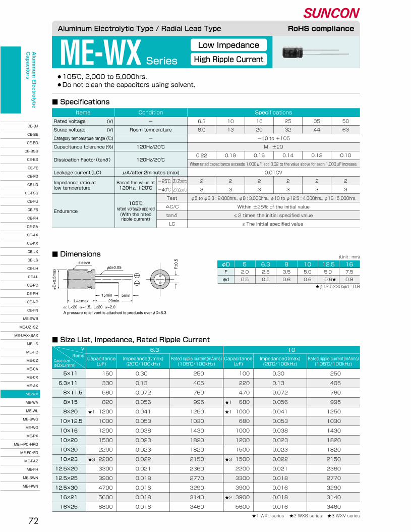
V 6.3
Rated ripple current(mArms)�(105℃/100kHz)
Capacitance�(μF)
ItemsImpedance(Ωmax)�(20℃/100kHz)
10
Rated ripple current(mArms)�(105℃/100kHz)
Capacitance�(μF)
Impedance(Ωmax)�(20℃/100kHz)
Case size�φDxL(mm)
72
●105℃, 2,000 to 5,000hrs.� ●Do not clean the capacitors using solvent.
ME-WX Series
■ Dimensions
■ Specifications
Low Impedance
High Ripple Current
φD 16F�
φd
7.5�
0.8
5.0�
0.6
5.0 �
0.6★�
3.5�
0.6
2.5�
0.5
2.0�
0.5
12.51086.35
(Unit : mm)
★φ12.5×30:φd=0.8
■ Size List, Impedance, Rated Ripple Current
5×11 �
6.3×11 �
8×11.5�
8×15 �
8×20 �
10×12.5�
10×16 �
10×20 �
10×20 �
10×23 �
12.5×20 �
12.5×25 �
12.5×30 �
16×21 �
16×25 �
150�
330�
560�
820�
1200�
1000�
1200�
1500�
2200�
2200�
3300�
3900�
4700�
5600�
6800
0.30�
0.13�
0.072�
0.056�
0.041�
0.053�
0.038�
0.023�
0.023�
0.022�
0.021�
0.018�
0.016�
0.018�
0.016
250�
405�
760�
995�
1250�
1030�
1430�
1820�
1820�
2150�
2360�
2770�
3290�
3140�
3460
★1 WXL series ★2 WXS series ★3 WXV series
★1�
�
�
�
�
★3
100�
220�
470�
680�
1000�
680�
1000�
1200�
1500�
1500�
2200�
3300�
3900�
3900�
5600
0.30�
0.13�
0.072�
0.056�
0.041�
0.053�
0.038�
0.023�
0.023�
0.022�
0.021�
0.018�
0.016�
0.018�
0.016
250�
405�
760�
995�
1250�
1030�
1430�
1820�
1820�
2150�
2360�
2770�
3290�
3140�
3460
★1�
★1�
�
�
�
�
★3�
�
�
�
★2
Aluminum Electrolytic Type / Radial Lead Type RoHS compliance
Endurance
105℃�rated voltage applied(With the rated�ripple current)
Impedance ratio at�low temperature
Based the value at�120Hz, +20℃�
Test�
△C/C�
tanδ�
LC
ー25℃�
ー40℃�
Z/Z20℃�
Z/Z20℃�
�
-40 to +105�
M : ±20�
�
When rated capacitance exceeds 1,000μF, add 0.02 to the value above for each 1,000μF increase.�
0.01CV�
�
�
6.3�
8.0�
�
�
0.22�
�
�
2�
3
10�
13�
�
�
0.19�
�
�
2�
3
16�
20�
�
�
0.16�
�
�
2�
3
25�
32�
�
�
0.14�
�
�
2�
3
35�
44�
�
�
0.12�
�
�
2�
3
50�
63�
�
�
0.10�
�
�
2�
3
SpecificationsConditionItems
Rated voltage�
Surge voltage�
Category temperature range�
Capacitance tolerance�
Dissipation Factor(tanδ)��
Leakage current(LC)�
(V)�
(V)�
(℃)�
(%)
-�
Room temperature�
-�
120Hz/20℃�
120Hz/20℃��
μA/after 2minutes (max)
φ5 to φ6.3 : 2,000hrs., φ8 : 3,000hrs., φ10 to φ12.5 : 4,000hrs., φ16 : 5,000hrs.�
Within ±25% of the initial value�
≤ 2 times the initial specified value�
≤ The initial specified value
L+αmax
φd±0.05 F±0.5sleeve
15min20min
5min
φD+0.5max
α: L<20 α=1.5, L≥20 α=2.0A pressure relief vent is attached to products over φD=6.3
Alu
min
um
Electro
lytic C
apacito
rs
CE-BJ�
CE-BE�
CE-BD�
CE-BSS�
CE-BS�
CE-FE�
CE-FD�
CE-LD�
CE-FSS�
CE-FU�
CE-FS�
CE-FH�
CE-GA�
CE-AX�
CE-KX�
CE-LX�
CE-LS�
CE-LH�
CE-LL�
CE-PC�
CE-PH�
CE-NP�
CE-FN�
ME-SWB�
ME-UZ・SZ�
ME-UAX・SAX�
ME-LS�
ME-HC�
ME-CZ�
ME-CA�
ME-CX�
ME-AX�
ME-WX�
ME-WA�
ME-WL�
ME-SWG�
ME-WG�
ME-PX�
ME-HPC・HPD�
ME-FC・FD�
ME-FAZ�
ME-FH�
ME-SWN�
ME-HWN
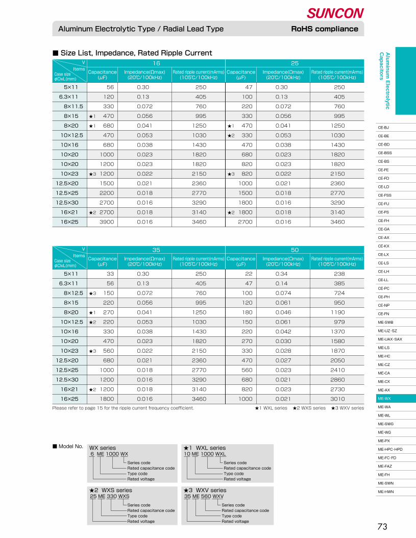
V 35
Rated ripple current(mArms)�(105℃/100kHz)
Capacitance�(μF)
ItemsImpedance(Ωmax)�(20℃/100kHz)
50
Rated ripple current(mArms)�(105℃/100kHz)
Capacitance�(μF)
Impedance(Ωmax)�(20℃/100kHz)
Case size�φDxL(mm)
V 16
Rated ripple current(mArms)�(105℃/100kHz)
Capacitance�(μF)
ItemsImpedance(Ωmax)�(20℃/100kHz)
25
Rated ripple current(mArms)�(105℃/100kHz)
Capacitance�(μF)
Impedance(Ωmax)�(20℃/100kHz)
Case size�φDxL(mm)
73
■ Size List, Impedance, Rated Ripple Current
5×11 �
6.3×11 �
8×11.5�
8×15 �
8×20 �
10×12.5�
10×16 �
10×20 �
10×20 �
10×23 �
12.5×20 �
12.5×25 �
12.5×30 �
16×21 �
16×25 �
5×11 �
6.3×11 �
8×12.5�
8×15 �
8×20 �
10×12.5�
10×16 �
10×20 �
10×23 �
12.5×20 �
12.5×25 �
12.5×30 �
16×21 �
16×25 �
■ Model No.
10 ME 1000 WXL
Series code�Rated capacitance code�Type code�Rated voltage
6 ME 1000 WX
Series code�Rated capacitance code�Type code�Rated voltage
25 ME 330 WXS
★1 WXL seriesWX series
★2 WXS series
Series code�Rated capacitance code�Type code�Rated voltage
35 ME 560 WXV★3 WXV series
Series code�Rated capacitance code�Type code�Rated voltage
★1 WXL series ★2 WXS series ★3 WXV seriesPlease refer to page 15 for the ripple current frequency coefficient.
56�
120�
330�
470�
680�
470�
680�
1000�
1200�
1200�
1500�
2200�
2700�
2700�
3900
0.30�
0.13�
0.072�
0.056�
0.041�
0.053�
0.038�
0.023�
0.023�
0.022�
0.021�
0.018�
0.016�
0.018�
0.016
250�
405�
760�
995�
1250�
1030�
1430�
1820�
1820�
2150�
2360�
2770�
3290�
3140�
3460
★1�
★1�
�
�
�
�
★3�
�
�
�
★2
33�
56�
150�
220�
270�
220�
330�
470�
560�
680�
1000�
1200�
1200�
1800
0.30�
0.13�
0.072�
0.056�
0.041�
0.053�
0.038�
0.023�
0.022�
0.021�
0.018�
0.016�
0.018�
0.016
250�
405�
760�
995�
1250�
1030�
1430�
1820�
2150�
2360�
2770�
3290�
3140�
3460
22�
47�
100�
120�
180�
150�
220�
270�
330�
470�
560�
680�
820�
1000
0.34�
0.14�
0.074�
0.061�
0.046�
0.061�
0.042�
0.030�
0.028�
0.027�
0.023�
0.021�
0.023�
0.021
238�
385�
724�
950�
1190�
979�
1370�
1580�
1870�
2050�
2410�
2860�
2730�
3010
★3�
�
★1�
★2�
�
�
★3�
�
�
�
★2
47�
100�
220�
330�
470�
330�
470�
680�
820�
820�
1000�
1500�
1800�
1800�
2700�
�
0.30�
0.13�
0.072�
0.056�
0.041�
0.053�
0.038�
0.023�
0.023�
0.022�
0.021�
0.018�
0.016�
0.018�
0.016
250�
405�
760�
995�
1250�
1030�
1430�
1820�
1820�
2150�
2360�
2770�
3290�
3140�
3460
★1�
★2�
�
�
�
★3�
�
�
�
★2
Aluminum Electrolytic Type / Radial Lead Type RoHS complianceA
lum
inu
m E
lectrolytic
Cap
acitors
CE-BJ�
CE-BE�
CE-BD�
CE-BSS�
CE-BS�
CE-FE�
CE-FD�
CE-LD�
CE-FSS�
CE-FU�
CE-FS�
CE-FH�
CE-GA�
CE-AX�
CE-KX�
CE-LX�
CE-LS�
CE-LH�
CE-LL�
CE-PC�
CE-PH�
CE-NP�
CE-FN�
ME-SWB�
ME-UZ・SZ�
ME-UAX・SAX�
ME-LS�
ME-HC�
ME-CZ�
ME-CA�
ME-CX�
ME-AX�
ME-WX�
ME-WA�
ME-WL�
ME-SWG�
ME-WG�
ME-PX�
ME-HPC・HPD�
ME-FC・FD�
ME-FAZ�
ME-FH�
ME-SWN�
ME-HWN
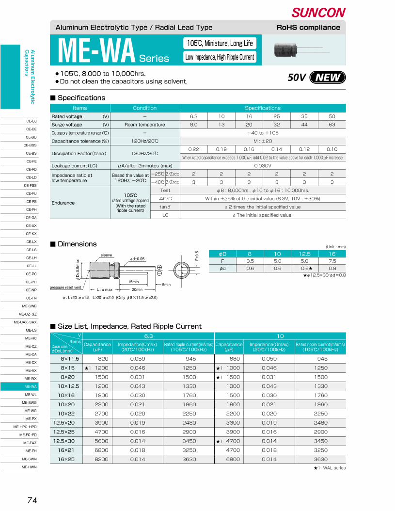
V 6.3
Rated ripple current(mArms)�(105℃/100kHz)
Capacitance�(μF)
ItemsImpedance(Ωmax)�(20℃/100kHz)
10
Rated ripple current(mArms)�(105℃/100kHz)
Capacitance�(μF)
Impedance(Ωmax)�(20℃/100kHz)
Case size�φDxL(mm)
74
●105℃, 8,000 to 10,000hrs.� ●Do not clean the capacitors using solvent.
ME-WA Series
■ Dimensions
■ Specifications
■ Size List, Impedance, Rated Ripple Current
105℃, Miniature, Long Life
Low Impedance, High Ripple Current
φD 16F�
φd
7.5�
0.8
12.55.0 �
0.6★�
105.0�
0.6
83.5�
0.6
(Unit : mm)
★φ12.5×30:φd=0.8
8×11.5�
8×15 �
8×20 �
10×12.5�
10×16 �
10×20 �
10×22 �
12.5×20 �
12.5×25 �
12.5×30 �
16×21 �
16×25 �
820�
1200�
1500�
1200�
1800�
2200�
2700�
3900�
4700�
5600�
6800�
8200
0.059�
0.046�
0.031�
0.043�
0.030�
0.021�
0.020�
0.019�
0.016�
0.014�
0.018�
0.014
945�
1250�
1500�
1330�
1760�
1960�
2250�
2480�
2900�
3450�
3250�
3630
★1 WAL series
★1
680�
1000�
1500�
1000�
1500�
1800�
2200�
3300�
3900�
4700�
4700�
6800
0.059�
0.046�
0.031�
0.043�
0.030�
0.021�
0.020�
0.019�
0.016�
0.014�
0.018�
0.014
945�
1250�
1500�
1330�
1760�
1960�
2250�
2480�
2900�
3450�
3250�
3630
★1�
★1�
�
�
�
�
�
�
★1
Aluminum Electrolytic Type / Radial Lead Type RoHS compliance
Endurance
105℃�rated voltage applied(With the rated�ripple current)
Impedance ratio at�low temperature
Based the value at�120Hz, +20℃�
Test�
△C/C�
tanδ�
LC
ー25℃�
ー40℃�
Z/Z20℃�
Z/Z20℃�
-40 to +105�
M : ±20�
�
When rated capacitance exceeds 1,000μF, add 0.02 to the value above for each 1,000μF increase.�
0.03CV�
�
16�
20�
�
�
0.16�
.�
�
2�
3�
�
6.3�
8.0�
�
�
0.22�
�
�
2�
3
10�
13�
�
�
0.19�
�
�
2�
3
25�
32�
�
�
0.14�
�
�
2�
3
50�
63�
�
�
0.10�
�
�
2�
3
35�
44�
�
�
0.12�
�
�
2�
3
SpecificationsConditionItems
Rated voltage�
Surge voltage�
Category temperature range�
Capacitance tolerance�
Dissipation Factor(tanδ)��
Leakage current(LC)�
(V)�
(V)�
(℃)�
(%)
-�
Room temperature�
-�
120Hz/20℃�
120Hz/20℃��
μA/after 2minutes (max)
φ8 : 8,000hrs., φ10 to φ16 : 10,000hrs.�
Within ±25% of the initial value (6.3V, 10V : ±30%)�
≤ 2 times the initial specified value�
≤ The initial specified value
pressure relief vent
sleeveφd±0.05 F
±0.5
15min
20min5min
φD+0.5max
L+αmax
α: L<20 α=1.5, L≥20 α=2.0 (Only φ8×11.5 α=2.0)
50V
Alu
min
um
Electro
lytic C
apacito
rs
CE-BJ�
CE-BE�
CE-BD�
CE-BSS�
CE-BS�
CE-FE�
CE-FD�
CE-LD�
CE-FSS�
CE-FU�
CE-FS�
CE-FH�
CE-GA�
CE-AX�
CE-KX�
CE-LX�
CE-LS�
CE-LH�
CE-LL�
CE-PC�
CE-PH�
CE-NP�
CE-FN�
ME-SWB�
ME-UZ・SZ�
ME-UAX・SAX�
ME-LS�
ME-HC�
ME-CZ�
ME-CA�
ME-CX�
ME-AX�
ME-WX�
ME-WA�
ME-WL�
ME-SWG�
ME-WG�
ME-PX�
ME-HPC・HPD�
ME-FC・FD�
ME-FAZ�
ME-FH�
ME-SWN�
ME-HWN

V 35
Rated ripple current(mArms)�(105℃/100kHz)
Capacitance�(μF)
ItemsImpedance(Ωmax)�(20℃/100kHz)
Case size�φDxL(mm)
V 16
Rated ripple current(mArms)�(105℃/100kHz)
Capacitance�(μF)
ItemsImpedance(Ωmax)�(20℃/100kHz)
25
Rated ripple current(mArms)�(105℃/100kHz)
Capacitance�(μF)
Impedance(Ωmax)�(20℃/100kHz)
Case size�φDxL(mm)
75
■ Model No.
16 ME 1000 WAL
Series code�Rated capacitance code�Type code�Rated voltage
10 ME 1000 WA
Series code�Rated capacitance code�Type code�Rated voltage
★1 WAL seriesWA series
■ Size List, Impedance, Rated Ripple Current
8×11.5�
8×15 �
8×20 �
10×12.5�
10×16 �
10×20 �
10×22 �
12.5×20 �
12.5×25 �
12.5×30 �
16×21 �
16×25 �
470�
680�
1000�
680�
1000�
1500�
1800�
2200�
2700�
3300�
3300�
4700
0.059�
0.046�
0.031�
0.043�
0.030�
0.021�
0.020�
0.019�
0.016�
0.014�
0.018�
0.014
945�
1250�
1500�
1330�
1760�
1960�
2250�
2480�
2900�
3450�
3250�
3630
★1�
★1�
�
�
�
�
�
�
★1
330�
390�
560�
470�
680�
820�
1000�
1500�
1800�
2200�
2200�
3300
0.059�
0.046�
0.031�
0.043�
0.030�
0.021�
0.020�
0.019�
0.016�
0.014�
0.018�
0.014
945�
1250�
1500�
1330�
1760�
1960�
2250�
2480�
2900�
3450�
3250�
3630
★1
8×11.5�
8×15 �
8×20 �
10×12.5�
10×16 �
10×20 �
10×22 �
12.5×20 �
12.5×25 �
12.5×30 �
16×21 �
16×25 �
220�
270�
390�
330�
470�
560�
680�
1000�
1200�
1500�
1500�
2200
0.059�
0.046�
0.031�
0.043�
0.030�
0.021�
0.020�
0.019�
0.016�
0.014�
0.018�
0.014
945�
1250�
1500�
1330�
1760�
1960�
2250�
2480�
2900�
3450�
3250�
3630
50
Rated ripple current(mArms)�(105℃/100kHz)
Capacitance�(μF)
Impedance(Ωmax)�(20℃/100kHz)
100�
120�
180�
150�
220�
270�
330�
470�
560�
680�
820�
1000
0.074�
0.061�
0.046�
0.061�
0.042�
0.030�
0.028�
0.027�
0.023�
0.021�
0.023�
0.021
724�
950�
1190�
979�
1370�
1580�
1870�
2050�
2410�
2860�
2730�
3010
★1
Please refer to page 15 for the ripple current frequency coefficient. ★1 WAL series
Aluminum Electrolytic Type / Radial Lead Type RoHS complianceA
lum
inu
m E
lectrolytic
Cap
acitors
CE-BJ�
CE-BE�
CE-BD�
CE-BSS�
CE-BS�
CE-FE�
CE-FD�
CE-LD�
CE-FSS�
CE-FU�
CE-FS�
CE-FH�
CE-GA�
CE-AX�
CE-KX�
CE-LX�
CE-LS�
CE-LH�
CE-LL�
CE-PC�
CE-PH�
CE-NP�
CE-FN�
ME-SWB�
ME-UZ・SZ�
ME-UAX・SAX�
ME-LS�
ME-HC�
ME-CZ�
ME-CA�
ME-CX�
ME-AX�
ME-WX�
ME-WA�
ME-WL�
ME-SWG�
ME-WG�
ME-PX�
ME-HPC・HPD�
ME-FC・FD�
ME-FAZ�
ME-FH�
ME-SWN�
ME-HWN
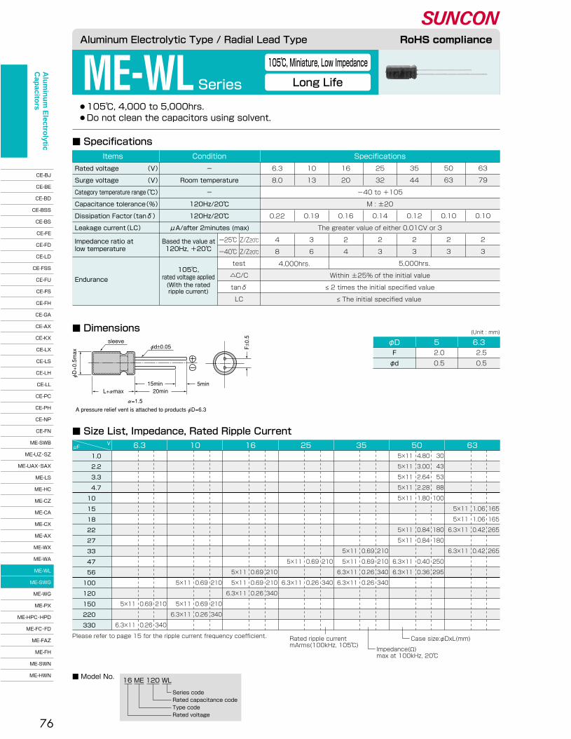
76
●105℃, 4,000 to 5,000hrs.� ●Do not clean the capacitors using solvent.
ME-WL Series
■ Dimensions
■ Specifications
■ Size List, Impedance, Rated Ripple Current
105℃, Miniature, Low Impedance
Long Life
φD 5 6.3F�
φd
2.0�
0.5
2.5�
0.5
(Unit : mm)
■ Model No.16 ME 120 WL
Series code�Rated capacitance code�Type code�Rated voltage
1.0�
2.2�
3.3�
4.7�
10 �
15 �
18 �
22 �
27 �
33 �
47 �
56 �
100 �
120 �
150 �
220 �
330 �
�
�
�
�
�
165�
165�
265�
�
265
�
�
�
�
�
1.06�
1.06�
0.42�
�
0.42
�
�
�
�
�
5×11�
5×11�
6.3×11�
�
6.3×11
30�
43�
53�
88�
100�
�
�
180�
180�
�
250�
295
4.80�
3.00�
2.64�
2.28�
1.80�
�
�
0.84�
0.84�
�
0.40�
0.36
5×11�
5×11�
5×11�
5×11�
5×11�
�
�
5×11�
5×11�
�
6.3×11�
6.3×11
�
�
�
�
�
�
�
�
�
210�
210�
340�
340
�
�
�
�
�
�
�
�
�
0.69�
0.69�
0.26�
0.26
�
�
�
�
�
�
�
�
�
5×11�
5×11�
6.3×11�
6.3×11
�
�
�
�
�
�
�
�
�
�
210�
�
340
�
�
�
�
�
�
�
�
�
�
0.69�
�
0.26
�
�
�
�
�
�
�
�
�
�
5×11�
�
6.3×11
�
�
�
�
�
�
�
�
�
�
�
210�
210�
340
�
�
�
�
�
�
�
�
�
�
�
0.69�
0.69�
0.26
�
�
�
�
�
�
�
�
�
�
�
5×11�
5×11�
6.3×11
�
�
�
�
�
�
�
�
�
�
�
�
210�
�
210�
340
�
�
�
�
�
�
�
�
�
�
�
�
0.69�
�
0.69�
0.26
�
�
�
�
�
�
�
�
�
�
�
�
5×11�
�
5×11�
6.3×11
�
�
�
�
�
�
�
�
�
�
�
�
�
�
210�
�
340
�
�
�
�
�
�
�
�
�
�
�
�
�
�
0.69�
�
0.26
�
�
�
�
�
�
�
�
�
�
�
�
�
�
5×11�
�
6.3×11
6.3μFV 10 16 25 35 50 63
Please refer to page 15 for the ripple current frequency coefficient. Rated ripple current�mArms(100kHz, 105℃)
Case size:φDxL(mm)
Impedance(Ω)�max at 100kHz, 20℃�
Aluminum Electrolytic Type / Radial Lead Type RoHS compliance
Endurance
Impedance ratio at�low temperature
Based the value at�120Hz, +20℃�
test�
△C/C�
tanδ�
LC
ー25℃�
ー40℃�
Z/Z20℃�
Z/Z20℃�
6.3�
8.0�
�
�
0.22�
�
4�
8
10�
13�
�
�
0.19�
�
3�
6
16�
20�
�
�
0.16�
�
2�
4
25�
32�
�
�
0.14�
�
2�
3
35�
44�
�
�
0.12�
�
2�
3�
5,000hrs.
50�
63�
�
�
0.10�
�
2�
3
63�
79�
�
�
0.10�
�
2�
3
SpecificationsConditionItems
Rated voltage�
Surge voltage�
Category temperature range�
Capacitance tolerance�
Dissipation Factor(tanδ)�
Leakage current(LC)�
(V)�
(V)�
(℃)�
(%)�
-�
Room temperature�
-�
120Hz/20℃�
120Hz/20℃�
μA/after 2minutes (max)
�
Within ±25% of the initial value�
≤ 2 times the initial specified value�
≤ The initial specified value
105℃,�rated voltage applied(With the rated�ripple current)
4,000hrs.
�
�
-40 to +105�
M : ±20�
�
The greater value of either 0.01CV or 3�
�
�
φD+0.5max
α=1.5
sleeveφd±0.05
5min15min20minL+αmax
F±0.5
A pressure relief vent is attached to products φD=6.3
Alu
min
um
Electro
lytic C
apacito
rs
CE-BJ�
CE-BE�
CE-BD�
CE-BSS�
CE-BS�
CE-FE�
CE-FD�
CE-LD�
CE-FSS�
CE-FU�
CE-FS�
CE-FH�
CE-GA�
CE-AX�
CE-KX�
CE-LX�
CE-LS�
CE-LH�
CE-LL�
CE-PC�
CE-PH�
CE-NP�
CE-FN�
ME-SWB�
ME-UZ・SZ�
ME-UAX・SAX�
ME-LS�
ME-HC�
ME-CZ�
ME-CA�
ME-CX�
ME-AX�
ME-WX�
ME-WA�
ME-WL�
ME-SWG�
ME-WG�
ME-PX�
ME-HPC・HPD�
ME-FC・FD�
ME-FAZ�
ME-FH�
ME-SWN�
ME-HWN

V 6.3Items
μF
Ripple current�(mArms)�105℃/100kHz
ESR�(Ωmax)�
20℃/100kHz
Case size�φDxL�(mm)
10Ripple current�(mArms)�105℃/100kHz
ESR�(Ωmax)�
20℃/100kHz
Case size�φDxL�(mm)
16Ripple current�(mArms)�105℃/100kHz
ESR�(Ωmax)�
20℃/100kHz
Case size�φDxL�(mm)
25Ripple current�(mArms)�105℃/100kHz
ESR�(Ωmax)�
20℃/100kHz
Case size�φDxL�(mm)
35Ripple current�(mArms)�105℃/100kHz
ESR�(Ωmax)�
20℃/100kHz
Case size�φDxL�(mm)
77
●105℃, 1,000 to 2,000hrs.� ●Do not clean the capacitors using solvent.
ME-SWGSeries
■ Dimensions
■ Specifications
■ Size List, ESR, Rated Ripple Current
Low ESR, Miniature
7mm Height
φD 5 6.3F�
φd
2.0�
0.45
2.5�
0.45
(Unit : mm)
■ Model No.25 ME 100 SWG
Series code�Rated capacitance code�Type code�Rated voltage
22�
39�
47�
56�
100�
150�
220�
330
�
�
�
�
5×7�
6.3×7�
6.3×7�
6.3×7
�
�
�
�
0.17�
0.082�
0.082�
0.082
�
�
�
0.17�
0.082�
0.082�
0.082
�
0.17�
�
�
0.082�
0.082
0.17�
0.17�
�
�
0.082
0.17�
�
0.082
�
�
�
�
390�
760�
760�
760
�
�
�
5×7�
6.3×7�
6.3×7�
6.3×7
�
�
�
390�
760�
760�
760
�
5×7�
�
�
6.3×7�
6.3×7
�
390�
�
�
760�
760
5×7�
5×7�
�
�
6.3×7
390�
390�
�
�
760
5×7�
�
6.3×7
390�
�
760
Please refer to page 15 for the ripple current frequency coefficient.
Aluminum Electrolytic Type / Radial Lead Type RoHS compliance
Endurance
105℃�rated voltage applied(With the rated�ripple current)
Impedance ratio at�low temperature
Based the value at�120Hz, +20℃�
Test�
△C/C�
tanδ�
LC
ー25℃�
ー40℃�
Z/Z20℃�
Z/Z20℃�
16�
20�
-40 to +105�
M : ±20�
0.16�
0.03CV�
2�
3�
�
6.3�
8.0�
�
�
0.24�
�
2�
3
10�
13�
�
�
0.20�
�
2�
3
25�
32�
�
�
0.14�
�
2�
3
35�
44�
�
�
0.12�
�
2�
3
SpecificationsConditionItems
Rated voltage�
Surge voltage�
Category temperature range�
Capacitance tolerance�
Dissipation Factor(tanδ)�
Leakage current(LC)�
(V)�
(V)�
(℃)�
(%)
-�
Room temperature�
-�
120Hz/20℃�
120Hz/20℃�
μA/after 2minutes (max)
φ5 : 1,000hrs., φ6.3 : 2,000hrs., (6ME330SWG, 10ME220SWG : 1,000hrs.)�
Within ±25% of the initial value (6.3V, 10V : ±30%)�
≤ 2 times the initial specified value�
≤ The initial specified value
φD+0.5max
sleeveφd±0.05
5min15min20minL+1.5max
F±0.5
Alu
min
um
Electro
lytic C
apacito
rs
CE-BJ�
CE-BE�
CE-BD�
CE-BSS�
CE-BS�
CE-FE�
CE-FD�
CE-LD�
CE-FSS�
CE-FU�
CE-FS�
CE-FH�
CE-GA�
CE-AX�
CE-KX�
CE-LX�
CE-LS�
CE-LH�
CE-LL�
CE-PC�
CE-PH�
CE-NP�
CE-FN�
ME-SWB�
ME-UZ・SZ�
ME-UAX・SAX�
ME-LS�
ME-HC�
ME-CZ�
ME-CA�
ME-CX�
ME-AX�
ME-WX�
ME-WA�
ME-WL�
ME-SWG�
ME-WG�
ME-PX�
ME-HPC・HPD�
ME-FC・FD�
ME-FAZ�
ME-FH�
ME-SWN�
ME-HWN

78
V 6.3Items
10 16 25
μF
Ripple current�(mArms)�105℃/100kHz
ESR�(mΩmax)�20℃/100kHz
Case size�φDxL�(mm)
Ripple current�(mArms)�105℃/100kHz
ESR�(mΩmax)�20℃/100kHz
Case size�φDxL�(mm)
Ripple current�(mArms)�105℃/100kHz
ESR�(mΩmax)�20℃/100kHz
Case size�φDxL�(mm)
Ripple current�(mArms)�105℃/100kHz
ESR�(mΩmax)�20℃/100kHz
Case size�φDxL�(mm)
ME-WGSeriesSuper Low ESR, Miniature
●105℃, 2,000 to 4,000hrs.� ●Do not clean the capacitors using solvent.
■ Specifications
■ Dimensions
φD 8 10F�
φd
3.5�
0.6
5.0�
0.6
(Unit : mm)
6 ME 1500 WGL
Series code�Rated capacitance code�Type code�Rated voltage
10 ME 1000 WG
Series code�Rated capacitance code�Type code�Rated voltage
★1 WGL series6 ME 1500 WGL2
Series code�Rated capacitance code�Type code�Rated voltage
★2 WGL2 seriesWG series25 ME 470 WGV★3 WGV series
Series code�Rated capacitance code�Type code�Rated voltage
■ Model No.
■ Size List, ESR, Rated Ripple Current
220�
330��
�
470�
�
680�
�820�
1000��
1200�
�
1500�
�
�
1800��
2200�
3300
�
�
★3�
★1�
�
★3�
�
★3�
�
★1
8×11.5�
8×11.5�
10×12.5�
8×20 �
10×12.5�
10×16 �
10×16 �
10×20 �
�
10×23 �
30�
32�
25�
18�
27�
20�
22�
16�
�
16
1110�
1080�
1440�
1820�
1390�
1920�
1830�
2180�
�
2180
�
�
�
�
�
�
★1�
�
�
★1
�
8×11.5�
�
8×11.5�
�
�
8×16 �
10×12.5�
�
8×20 �
10×16 �
�
10×20 �
�
�
�
10×23 �
�
30�
�
36�
�
�
28�
26�
�
19�
19�
�
13�
�
�
�
12
�
1140�
�
1140�
�
�
1490�
1540�
�
1870�
2000�
�
2550�
�
�
�
2800
�
�
�
�
�
�
�
�
�
★1�
�
★1�
★1
�
�
�
8×11.5�
�
�
8×11.5�
�
�
8×16 �
10×12.5�
8×20 �
8×20 �
10×16 �
�
�
10×20 �
�
10×23 �
�
�
�
30�
�
�
36�
�
�
28�
26�
19�
19�
19�
�
�
13�
�
12
�
�
�
1140�
�
�
1140�
�
�
1490�
1540�
1870�
1870�
2000�
�
�
2550�
�
2800
�
�
�
�
�
�
�
�
�
�
�
�
★1�
★2�
�
★3�
★2
�
�
�
�
�
�
�
�
8×11.5�
8×11.5�
�
8×16 �
8×20 �
8×20 �
10×12.5�
10×16 �
8×20 �
10×16 �
10×20 �
10×23 �
�
�
�
�
�
�
�
�
36�
30�
�
28�
19�
16�
26�
18�
16�
19�
13�
12
�
�
�
�
�
�
�
�
1140�
1140�
�
1490�
1870�
1950�
1540�
2000�
1950�
2000�
2550�
2800
Please refer to page 15 for the ripple current frequency coefficient. ★1 WGL series ★2 WGL2 series ★3 WGV series
Aluminum Electrolytic Type / Radial Lead Type RoHS compliance
Endurance
105℃�rated voltage applied(With the rated�ripple current)
Impedance ratio at�low temperature
Based the value at�120Hz, +20℃�
Test�
△C/C�
tanδ�
LC
ー25℃�
ー40℃�
Z/Z20℃�
Z/Z20℃�
�
-40 to +105�
M : ±20�
�
When rated capacitance exceeds 1,000μF, add 0.02 to the value above for each 1,000μF increase.�
0.03CV�
�
6.3�
8.0�
�
�
0.22�
�
�
2�
3
10�
13�
�
�
0.19�
�
�
2�
3
16�
20�
�
�
0.16�
�
�
2�
3
25�
32�
�
�
0.14�
�
�
2�
3
SpecificationsConditionItems
Rated voltage�
Surge voltage�
Category temperature range�
Capacitance tolerance�
Dissipation Factor(tanδ)��
Leakage current(LC)�
(V)�
(V)�
(℃)�
(%)
-�
Room temperature�
-�
120Hz/20℃�
120Hz/20℃��
μA/after 2minutes (max)
φ8×11.5, φ8×16, φ10×12.5, φ10×16 : 2,000hrs., φ8×20 : 3,000hrs., φ10×20, φ10×23 : 4,000hrs.�
Within ±25% of the initial value�
≤ 2 times the initial specified value�
≤ The initial specified value
pressure�relief vent
α : L<20 α=1.5, L≥20 α=2.0 (Only φ8×11.5 α=2.0)
sleeveφd±0.05
φD+0.5max
5min15min20minL+αmax
F±0.5
Alu
min
um
Electro
lytic C
apacito
rs
CE-BJ�
CE-BE�
CE-BD�
CE-BSS�
CE-BS�
CE-FE�
CE-FD�
CE-LD�
CE-FSS�
CE-FU�
CE-FS�
CE-FH�
CE-GA�
CE-AX�
CE-KX�
CE-LX�
CE-LS�
CE-LH�
CE-LL�
CE-PC�
CE-PH�
CE-NP�
CE-FN�
ME-SWB�
ME-UZ・SZ�
ME-UAX・SAX�
ME-LS�
ME-HC�
ME-CZ�
ME-CA�
ME-CX�
ME-AX�
ME-WX�
ME-WA�
ME-WL�
ME-SWG�
ME-WG�
ME-PX�
ME-HPC・HPD�
ME-FC・FD�
ME-FAZ�
ME-FH�
ME-SWN�
ME-HWN
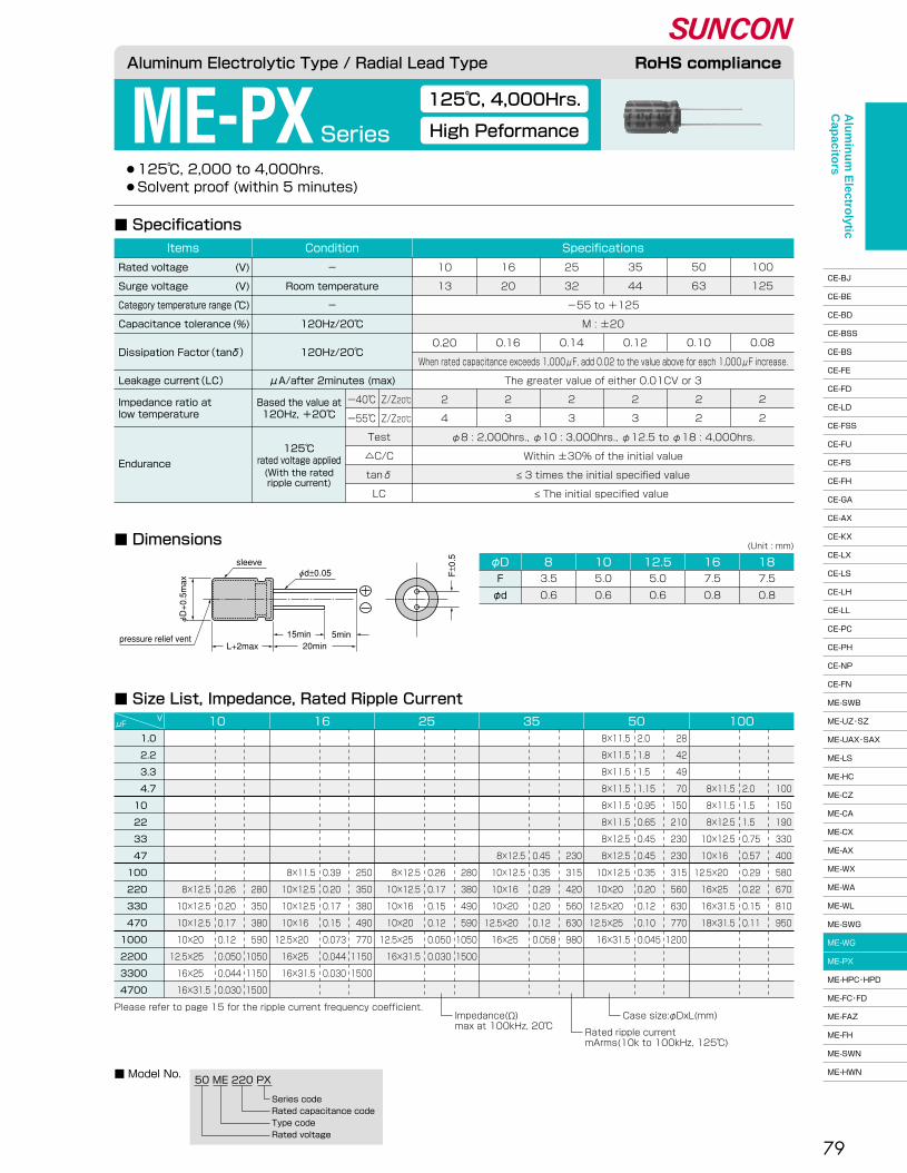
79
●125℃, 2,000 to 4,000hrs.� ●Solvent proof (within 5 minutes)
ME-PX Series
125℃, 4,000Hrs.
High Peformance
■ Dimensions
■ Specifications
■ Size List, Impedance, Rated Ripple Current
φDF�
φd
7.5�
0.8
187.5�
0.8
165.0�
0.6
12.55.0�
0.6
103.5�
0.6
8
(Unit : mm)
■ Model No.50 ME 220 PX
Series code�Rated capacitance code�Type code�Rated voltage
1.0�
2.2�
3.3�
4.7�
10 �
22 �
33 �
47 �
100 �
220 �
330 �
470 �
1000 �
2200 �
3300 �
4700 �
μFV 10
�
�
�
�
�
�
�
�
�
8×12.5�
10×12.5�
10×12.5�
10×20 �
12.5×25 �
16×25 �
16×31.5
�
�
�
�
�
�
�
�
�
280�
350�
380�
590�
1050�
1150�
1500
�
�
�
�
�
�
�
�
�
0.26�
0.20�
0.17�
0.12�
0.050�
0.044�
0.030
16�
�
�
�
�
�
�
�
8×11.5�
10×12.5�
10×12.5�
10×16 �
12.5×20 �
16×25 �
16×31.5
�
�
�
�
�
�
�
�
250�
350�
380�
490�
770�
1150�
1500
�
�
�
�
�
�
�
�
0.39�
0.20�
0.17�
0.15�
0.073�
0.044�
0.030
25�
�
�
�
�
�
�
�
8×12.5�
10×12.5�
10×16 �
10×20 �
12.5×25 �
16×31.5
�
�
�
�
�
�
�
�
280�
380�
490�
590�
1050�
1500
�
�
�
�
�
�
�
�
0.26�
0.17�
0.15�
0.12�
0.050�
0.030
35�
�
�
�
�
�
�
8×12.5�
10×12.5�
10×16 �
10×20 �
12.5×20 �
16×25 �
�
�
�
�
�
�
�
230�
315�
420�
560�
630�
980
�
�
�
�
�
�
�
0.45�
0.35�
0.29�
0.20�
0.12�
0.058
508×11.5�
8×11.5�
8×11.5�
8×11.5�
8×11.5�
8×11.5�
8×12.5�
8×12.5�
10×12.5�
10×20 �
12.5×20 �
12.5×25 �
16×31.5
28�
42�
49�
70�
150�
210�
230�
230�
315�
560�
630�
770�
1200
2.0�
1.8�
1.5�
1.15�
0.95�
0.65�
0.45�
0.45�
0.35�
0.20�
0.12�
0.10�
0.045
100�
�
�
8×11.5�
8×11.5�
8×12.5�
10×12.5�
10×16 �
12.5×20 �
16×25 �
16×31.5�
18×31.5
�
�
�
100�
150�
190�
330�
400�
580�
670�
810�
950
�
�
�
2.0�
1.5�
1.5�
0.75�
0.57�
0.29�
0.22�
0.15�
0.11
Please refer to page 15 for the ripple current frequency coefficient.
Rated ripple current�mArms(10k to 100kHz, 125℃)
Case size:φDxL(mm)Impedance(Ω)�max at 100kHz, 20℃�
Aluminum Electrolytic Type / Radial Lead Type RoHS compliance
Endurance
125℃�rated voltage applied(With the rated�ripple current)
Impedance ratio at�low temperature
Based the value at�120Hz, +20℃�
Test�
△C/C�
tanδ�
LC
ー40℃�
ー55℃�
Z/Z20℃�
Z/Z20℃�
�
-55 to +125�
M : ±20�
�
When rated capacitance exceeds 1,000μF, add 0.02 to the value above for each 1,000μF increase.�
The greater value of either 0.01CV or 3�
�
�
10�
13�
�
�
0.20�
�
�
2�
4
16�
20�
�
�
0.16�
�
�
2�
3
25�
32�
�
�
0.14�
�
�
2�
3
35�
44�
�
�
0.12�
�
�
2�
3
50�
63�
�
�
0.10�
�
�
2�
2
100�
125�
�
�
0.08�
�
�
2�
2
SpecificationsConditionItems
Rated voltage�
Surge voltage�
Category temperature range�
Capacitance tolerance�
Dissipation Factor(tanδ)��
Leakage current(LC)�
(V)�
(V)�
(℃)�
(%)
-�
Room temperature�
-�
120Hz/20℃�
120Hz/20℃��
μA/after 2minutes (max)
φ8 : 2,000hrs., φ10 : 3,000hrs., φ12.5 to φ18 : 4,000hrs.�
Within ±30% of the initial value�
≤ 3 times the initial specified value�
≤ The initial specified value
F±0.5
φd±0.05sleeve
5min15min20minL+2max
φD+0.5max
pressure relief vent
Alu
min
um
Electro
lytic C
apacito
rs
CE-BJ�
CE-BE�
CE-BD�
CE-BSS�
CE-BS�
CE-FE�
CE-FD�
CE-LD�
CE-FSS�
CE-FU�
CE-FS�
CE-FH�
CE-GA�
CE-AX�
CE-KX�
CE-LX�
CE-LS�
CE-LH�
CE-LL�
CE-PC�
CE-PH�
CE-NP�
CE-FN�
ME-SWB�
ME-UZ・SZ�
ME-UAX・SAX�
ME-LS�
ME-HC�
ME-CZ�
ME-CA�
ME-CX�
ME-AX�
ME-WX�
ME-WA�
ME-WL�
ME-SWG�
ME-WG�
ME-PX�
ME-HPC・HPD�
ME-FC・FD�
ME-FAZ�
ME-FH�
ME-SWN�
ME-HWN

80
●Do not clean the capacitors using solvent.
ME-HPC・HPDSeries
Miniature, Mid. and High Voltage
Low Profile, Mid. and High Voltage
■ Dimensions
■ Size List, Rated Ripple Current
■ Specifications
φD 5 6.3 8 10 12.5 16 18F�
φd
2.0�
0.5
2.5�
0.5
3.5�
0.6
5.0�
0.6
5.0�
0.6
7.5�
0.8
7.5�
0.8
(Unit : mm)
160 ME 33 HPCSeries code�Rated capacitance code�Type code�Rated voltage
HPC �series
450 ME 10 HPDSeries code�Rated capacitance code�Type code�Rated voltage
HPD �series
■ Model No.
0.47�
1.0 �
2.2 �
3.3 �
4.7 �
10 �
�
22 �
�
33 �
�
47 �
�
68 �
�
82 �
�
100 �
�
150 �
�
220 �
μFV 160 200 250 350 400 450
�
8×12.5�
10×16 �
10×20 �
12.5×20 �
12.5×25 �
16×21 �
16×25 �
18×21 �
16×30 �
18×25 �
18×35.5
�
26�
40�
52�
67�
100�
�
180�
�
220�
�
245
Please refer to page 15 for the ripple current frequency coefficient.�Upper : HPC series(0.47μF to 4.7μF:HPC series)�Lower : HPD series
Rated ripple current�mArms(120Hz, 85℃)
Case size:φDxL(mm)
5×11 �
5×11 �
6.3×11 �
6.3×11 �
6.3×11 �
8×11.5�
�
10×12.5�
�
10×20 �
�
12.5×20 �
�
12.5×20 �
�
12.5×25 �
16×21 �
12.5×25 �
16×21 �
16×30 �
18×25 �
16×35.5�
18×30.5
10�
21�
31�
40�
55�
90�
�
153�
�
195�
�
245�
�
310�
�
380�
�
410�
�
550�
�
745
5×11 �
5×11 �
6.3×11 �
6.3×11 �
8×11.5�
8×12.5�
�
10×16 �
�
10×20 �
�
12.5×20 �
�
12.5×25 �
16×21 �
�
16×21 �
16×25 �
18×21 �
16×35.5�
18×30.5�
18×35.5
11�
23�
34�
46�
57�
92�
�
160�
�
210�
�
250�
�
325�
�
390�
�
430�
�
575�
�
760
5×11 �
5×11 �
6.3×11 �
8×11.5�
8×11.5�
10×12.5�
�
10×20 �
�
12.5×20 �
�
12.5×25 �
16×21 �
16×25 �
18×21 �
16×30 �
18×25 �
16×30 �
18×25 �
18×35.5
12�
25�
35�
48�
59�
94�
�
170�
�
220�
�
260�
�
335�
�
400�
�
432�
�
588
6.3×11 �
6.3×11 �
8×11.5�
8×12.5�
10×12.5�
10×16 �
�
12.5×20 �
�
12.5×25 �
16×21 �
16×25 �
18×21 �
16×35.5�
18×25 �
18×30.5�
�
18×35.5
14�
29�
40�
52�
67�
100�
�
175�
�
225�
�
260�
�
340�
�
405�
�
440
6.3×11 �
8×11.5�
8×11.5�
10×12.5�
10×16 �
10×20 �
�
12.5×25 �
16×21 �
16×25 �
18×21 �
16×30 �
18×25 �
16×35.5�
18×30.5�
18×35.5
14�
29�
40�
52�
67�
100�
�
180�
�
230�
�
270�
�
345�
�
420
Aluminum Electrolytic Type / Radial Lead Type RoHS compliance
Endurance
85℃, 2,000hrs.�rated voltage applied(With the rated�ripple current)
Impedance ratio at�low temperature
Based the value at�120Hz, +20℃�
μA/after�2minutes (max)
△C/C�
tanδ�
LC
ー25℃�
ー40℃�
Z/Z20℃�
Z/Z20℃�
M : ±20�
�
0.03CV +15�
0.02CV +25
160�
200�
�
�
0.20�
�
�
3�
6
200�
250�
-40 to +85�
�
0.20�
�
�
3�
6
250�
300�
�
�
0.20�
�
�
3�
6
350�
400�
�
�
0.25�
�
�
4�
-�
400�
450�
-25 to +85�
�
0.25�
�
�
6�
-�
450�
500�
�
�
0.25�
�
�
12�
-�
SpecificationsConditionItemsRated voltage�
Surge voltage�
Category temperature range�
Capacitance tolerance�
Dissipation Factor(tanδ)�
Leakage current(LC)�
(V)�
(V)�
(℃)�
(%)
-�
Room temperature�
-�
120Hz/20℃�
120Hz/20℃�
Within ±20% of the initial value�
≤ 2 times the initial specified value�
≤ The initial specified value
CV ≤ 1,000�
CV > 1,000
α : L<20 α=1.5, L≥20 α=2.0
φd±0.05 F±0.5sleeve
L+αmax15min20min
5min
φD+0.5max
A pressure relief vent is attached to products over φD=6.3
Alu
min
um
Electro
lytic C
apacito
rs
CE-BJ�
CE-BE�
CE-BD�
CE-BSS�
CE-BS�
CE-FE�
CE-FD�
CE-LD�
CE-FSS�
CE-FU�
CE-FS�
CE-FH�
CE-GA�
CE-AX�
CE-KX�
CE-LX�
CE-LS�
CE-LH�
CE-LL�
CE-PC�
CE-PH�
CE-NP�
CE-FN�
ME-SWB�
ME-UZ・SZ�
ME-UAX・SAX�
ME-LS�
ME-HC�
ME-CZ�
ME-CA�
ME-CX�
ME-AX�
ME-WX�
ME-WA�
ME-WL�
ME-SWG�
ME-WG�
ME-PX�
ME-HPC・HPD�
ME-FC・FD�
ME-FAZ�
ME-FH�
ME-SWN�
ME-HWN

81
ME-FC・FD Series
105℃ Miniature, Mid. and High Voltage
105℃ Low Profile, Mid. and High Voltage
●105℃, 1,000 to 2,000hrs.� ●Do not clean the capacitors using solvent.
■ Size List, Rated Ripple Current
■ Dimensions
■ Specifications
160 ME 33 FCSeries code�Rated capacitance code�Type code�Rated voltage
450 ME 10 FDSeries code�Rated capacitance code�Type code�Rated voltage
0.47�
1.0 �
2.2 �
3.3 �
4.7 �
10 �
�
22 �
�
33 �
�
47 �
�
68 �
�
82 �
�
100 �
�
150 �
�
220 �
μFV 160 200 250 350 400 450
5×11 �
5×11 �
6.3×11 �
6.3×11 �
6.3×11 �
8×11.5�
�
10×12.5�
�
10×20 �
�
12.5×20 �
�
12.5×20 �
�
12.5×25 �
16×21 �
12.5×25 �
16×21 �
16×30 �
18×25 �
16×35.5�
18×30.5
7.0�
15 �
22 �
28 �
39 �
63 �
�
107 �
�
137 �
�
172 �
�
217 �
�
270 �
�
287 �
�
385 �
�
522 �
5×11 �
5×11 �
6.3×11 �
6.3×11 �
8×11.5�
8×12.5�
�
10×16 �
�
10×20 �
�
12.5×20 �
�
12.5×25 �
16×21 �
�
16×21 �
16×25 �
18×21 �
16×35.5�
18×30.5�
18×35.5
8.0�
16 �
24 �
32 �
40 �
64 �
�
112 �
�
147 �
�
175 �
�
228 �
�
277 �
�
301 �
�
403 �
�
532 �
5×11 �
5×11 �
6.3×11 �
8×11.5�
8×11.5�
10×12.5�
�
10×20 �
�
12.5×20 �
�
12.5×25 �
16×21 �
16×25 �
16×21 �
16×30 �
18×25 �
16×35.5�
18×25 �
18×35.5
8.0�
18 �
25 �
34 �
41 �
66 �
�
119 �
�
154 �
�
182 �
�
235 �
�
284 �
�
302 �
�
412 �
6.3×11 �
6.3×11 �
8×11.5�
8×12.5�
10×12.5�
10×20 �
�
12.5×25 �
16×21 �
16×25 �
18×21 �
16×30 �
18×25 �
16×35.5�
18×30.5�
18×35.5
10�
20�
28�
36�
47�
70�
�
123�
�
158�
�
182�
�
242�
�
294
6.3×11 �
8×11.5�
8×11.5�
10×12.5�
10×16 �
10×20 �
�
12.5×25 �
16×21 �
16×25 �
18×21 �
16×30 �
18×25 �
18×35.5
10�
20�
28�
36�
47�
70�
�
126�
�
161�
�
189�
�
249
�
8×12.5�
10×16 �
10×20 �
12.5×20 �
12.5×25 �
16×21 �
16×25 �
18×21 �
16×30 �
18×25 �
18×35.5
�
18�
28�
36�
47�
70�
�
125�
�
154�
�
172
Rated ripple current�mArms(120Hz, 105℃)
Case size:φDxL(mm)Upper:FC series(0.47μF to 4.7μF:FC series)�Lower:FD series�Please refer to page 15 for the ripple current frequency coefficient.
φD 5 6.3 8 10 12.5 16 18F�
φd
2.0�
0.5
2.5�
0.5
3.5�
0.6
5.0�
0.6
5.0�
0.6
7.5�
0.8
7.5�
0.8
(Unit : mm)
Aluminum Electrolytic Type / Radial Lead Type RoHS compliance
FC �series
FD �series
■ Model No.
Endurance
105℃�rated voltage applied(With the rated�ripple current)
Impedance ratio at�low temperature
Based the value at�120Hz, +20℃�
μA/after�2minutes (max)
Test�
△C/C�
tanδ�
LC
CV ≤ 1,000�
CV > 1,000
ー25℃�
ー40℃�
Z/Z20℃�
Z/Z20℃�
M : ±20�
�
0.03CV + 15�
0.02CV + 25
160�
200�
�
�
0.20�
�
�
3�
6
200�
250�
�
�
0.20�
�
�
3�
6
250�
300�
-40 to +105�
�
0.20�
�
�
3�
6
350�
400�
�
�
0.25�
�
�
4�
8
400�
450�
�
�
0.25�
�
�
6�
10
450�
500�
-25 to +105�
�
0.25�
�
�
6�
-�
SpecificationsConditionItems
Rated voltage�
Surge voltage�
Category temperature range�
Capacitance tolerance�
Dissipation Factor(tanδ)�
Leakage current(LC)�
(V)�
(V)�
(℃)�
(%)
-�
Room temperature�
-�
120Hz/20℃�
120Hz/20℃�
φ5 to φ8 : 1,000hrs., φ10 to φ18 : 2,000hrs.�
Within ±20% of the initial value�
≤ 2 times the initial specified value�
≤ The initial specified value
φd±0.05 F±0.5
15min 5min20minL+αmax
sleeve
φD+0.5max
α : L<20 α=1.5, L≥20 α=2.0�A pressure relief vent is attached to products over φD=6.3
Alu
min
um
Electro
lytic C
apacito
rs
CE-BJ�
CE-BE�
CE-BD�
CE-BSS�
CE-BS�
CE-FE�
CE-FD�
CE-LD�
CE-FSS�
CE-FU�
CE-FS�
CE-FH�
CE-GA�
CE-AX�
CE-KX�
CE-LX�
CE-LS�
CE-LH�
CE-LL�
CE-PC�
CE-PH�
CE-NP�
CE-FN�
ME-SWB�
ME-UZ・SZ�
ME-UAX・SAX�
ME-LS�
ME-HC�
ME-CZ�
ME-CA�
ME-CX�
ME-AX�
ME-WX�
ME-WA�
ME-WL�
ME-SWG�
ME-WG�
ME-PX�
ME-HPC・HPD�
ME-FC・FD�
ME-FAZ�
ME-FH�
ME-SWN�
ME-HWN

82
ME-FAZ Series
Low Impedance
High Ripple, Mid. Voltage
●105℃, 1,000 to 2,000hrs.� ●Do not clean the capacitors using solvent.
■ Specifications
■ Dimensions
■ Size List, Impedance, Rated Ripple Current
■ Model No.250 ME 1 FAZ
Series code�Rated capacitance code�Type code�Rated voltage
φDF�
φd
7.5�
0.8
187.5�
0.8
165.0�
0.6
12.55.0�
0.6
103.5�
0.6
8
(Unit : mm)
1.0�
2.2�
3.3�
4.7�
10 �
22 �
33 �
47 �
100 �
150 �
220 �
μFV 160 180 200 250
8×11.5�
8×11.5�
8×11.5�
10×12.5�
10×16 �
12.5×20 �
12.5×25 �
16×25 �
16×35.5�
18×35.5
4.83�
3.93�
3.29�
1.89�
1.32�
0.58�
0.54�
0.39�
0.17�
0.12
64�
86�
116�
160�
253�
440�
546�
665�
751�
955
8×11.5�
8×11.5�
8×11.5�
8×12.5�
10×12.5�
10×20 �
12.5×20 �
12.5×25 �
16×30 �
18×35.5
6.30�
4.65�
3.12�
1.65�
1.24�
0.85�
0.50�
0.38�
0.17�
0.12
56�
79�
106�
151�
233�
423�
530�
659�
740�
917
�
�
8×11.5�
8×11.5�
8×12.5�
10×16 �
10×20 �
12.5×20 �
16×25 �
16×35.5�
18×35.5
�
�
3.12�
2.58�
2.05�
0.96�
0.54�
0.41�
0.24�
0.12�
0.10
�
�
106�
117�
212�
389�
515�
638�
728�
892�
1134
�
�
8×11.5�
8×11.5�
8×12.5�
10×16 �
10×20 �
12.5×20 �
16×25 �
16×30 �
16×35.5
�
�
3.12�
2.58�
2.05�
0.96�
0.54�
0.41�
0.24�
0.13�
0.11
�
�
106�
117�
212�
389�
515�
638�
728�
844�
1113
Rated ripple current�mArms(100kHz, 105℃)
Please refer to page 15 for the ripple current frequency coefficient.
Case size:φDxL(mm)Impedance(Ω)�max at 100kHz, 20℃�
Aluminum Electrolytic Type / Radial Lead Type RoHS compliance
Endurance
105℃�rated voltage applied(With the rated�ripple current)
Impedance ratio at�low temperature
Based the value at�120Hz, +20℃�
Test�
△C/C�
tanδ�
LC
ー25℃�
ー40℃�
Z/Z20℃�
Z/Z20℃�
-40 to +105�
M : ±20�
�
0.03CV + 15�
0.02CV + 25
160�
200�
�
�
0.10�
�
�
3�
5
180�
225�
�
�
0.10�
�
�
3�
5
200�
250�
�
�
0.10�
�
�
3�
5
250�
300�
�
�
0.10�
�
�
3�
5
SpecificationsConditionItems
Rated voltage�
Surge voltage�
Category temperature range�
Capacitance tolerance�
Dissipation Factor(tanδ)�
Leakage current(LC)�
(V)�
(V)�
(℃)�
(%)
-�
Room temperature�
-�
120Hz/20℃�
120Hz/20℃�
φ8 : 1,000hrs., φ10 to φ18 : 2,000hrs.�
Within ±20% of the initial value�
≤ 2 times the initial specified value�
≤ The initial specified value
CV ≤ 1,000�
CV > 1,000
μA/after�2minutes (max)
α : L<20 α=1.5, L≥20 α=2.0
15min 5min
F±0.5
φd±0.05sleeve
φD+0.5max
L+αmax 20minpressure relief vent
Alu
min
um
Electro
lytic C
apacito
rs
CE-BJ�
CE-BE�
CE-BD�
CE-BSS�
CE-BS�
CE-FE�
CE-FD�
CE-LD�
CE-FSS�
CE-FU�
CE-FS�
CE-FH�
CE-GA�
CE-AX�
CE-KX�
CE-LX�
CE-LS�
CE-LH�
CE-LL�
CE-PC�
CE-PH�
CE-NP�
CE-FN�
ME-SWB�
ME-UZ・SZ�
ME-UAX・SAX�
ME-LS�
ME-HC�
ME-CZ�
ME-CA�
ME-CX�
ME-AX�
ME-WX�
ME-WA�
ME-WL�
ME-SWG�
ME-WG�
ME-PX�
ME-HPC・HPD�
ME-FC・FD�
ME-FAZ�
ME-FH�
ME-SWN�
ME-HWN

83
●105℃, 10,000hrs.� ●Do not clean the capacitors using solvent.
ME-FHSeries
105℃, Miniature, Long Life
Mid. and High Voltage
■ Dimensions
■ Size List, Rated Ripple Current
■ Specifications
■ Model No.200 ME 33 FH
Series code�Rated capacitance code�Type code�Rated voltage
φD 18F�
φd
7.5�
0.8
167.5�
0.8
12.55.0�
0.6
105.0�
0.6
(Unit : mm)
6.8�
10 �
22 �
33 �
47 �
68 �
82 �
100 �
150 �
220 �
μFV 160 200 250 350 400 450
10×20 �
12.5×20 �
16×25 �
16×31.5�
18×31.5�
18×41 �
58�
145�
218�
243�
304�
340
�
10×20 �
12.5×25 �
16×25 �
16×31.5�
18×31.5�
�
18×41 �
�
108�
195�
249�
292�
346�
�
500
�
10×16 �
12.5×20 �
12.5×25 �
16×25 �
16×31.5�
18×31.5
�
100�
184�
224�
282�
334�
360
�
10×16 �
10×20 �
12.5×20 �
12.5×25 �
16×25 �
16×25 �
16×31.5�
18×31.5
�
106�
184�
238�
282�
364�
403�
418�
545
�
�
10×16 �
10×20 �
12.5×20 �
12.5×20 �
12.5×25 �
16×25 �
16×31.5�
18×31.5
�
�
173�
227�
270�
325�
370�
436�
470�
660
�
�
�
10×16 �
10×20 �
12.5×20 �
12.5×20 �
12.5×25 �
16×25 �
16×31.5
�
�
�
190�
270�
336�
346�
410�
500�
570
Please refer to page 15 for the ripple current frequency coefficient.Rated ripple current�mArms(120Hz, 105℃)
Case size:φDxL(mm)
Aluminum Electrolytic Type / Radial Lead Type RoHS compliance
Endurance
105℃, 10,000hrs.�rated voltage applied(With the rated�ripple current)
Impedance ratio at�low temperature
Based the value at�120Hz, +20℃�
△C/C�
tanδ�
LC
ー25℃�
ー40℃�
Z/Z20℃�
Z/Z20℃�
�
�
M : ±20�
�
0.02CV + 25�
�
�
160�
200�
�
�
0.20�
�
3�
6
200�
250�
�
�
0.20�
�
3�
6
250�
300�
-40 to +105�
�
0.20�
�
3�
6
350�
400�
�
�
0.25�
�
4�
8
400�
450�
�
�
0.25�
�
6�
10
450�
500�
-25 to +105�
�
0.25�
�
6�
-�
SpecificationsConditionItems
Rated voltage�
Surge voltage�
Category temperature range�
Capacitance tolerance�
Dissipation Factor(tanδ)�
Leakage current(LC)�
(V)�
(V)�
(℃)�
(%)
-�
Room temperature�
-�
120Hz/20℃�
120Hz/20℃�
μA/after 2minutes (max)
Within ±20% of the initial value�
≤ 2 times the initial specified value�
≤ The initial specified value
sleeveφd±0.05 F
±0.5
15min
20min
5min.φD+0.5max
L+αmax
α : L<20 α=1.5, L≥20 α=2.0
pressure relief vent
Alu
min
um
Electro
lytic C
apacito
rs
CE-BJ�
CE-BE�
CE-BD�
CE-BSS�
CE-BS�
CE-FE�
CE-FD�
CE-LD�
CE-FSS�
CE-FU�
CE-FS�
CE-FH�
CE-GA�
CE-AX�
CE-KX�
CE-LX�
CE-LS�
CE-LH�
CE-LL�
CE-PC�
CE-PH�
CE-NP�
CE-FN�
ME-SWB�
ME-UZ・SZ�
ME-UAX・SAX�
ME-LS�
ME-HC�
ME-CZ�
ME-CA�
ME-CX�
ME-AX�
ME-WX�
ME-WA�
ME-WL�
ME-SWG�
ME-WG�
ME-PX�
ME-HPC・HPD�
ME-FC・FD�
ME-FAZ�
ME-FH�
ME-SWN�
ME-HWN
10×16
18×35.5
88
420

84
ME-SWN Series
Bi-polar
7mm Height
●85℃, 1,000hrs.� ●Solvent proof (within 3 minutes)
■ Specifications
■ Dimensions
■ Size List, Rated Ripple Current
φD 4F�
φd
1.5 �
0.45
52.0 �
0.45
6.32.5 �
0.45
(Unit : mm)
■ Model No.16 ME 33 SWN
Series code�Rated capacitance code�Type code�Rated voltage
1.0 �
2.2 �
3.3 �
4.7 �
10 �
22 �
33 �
47 �
μFV 6.3 10 16 25 35 50
4×7�
5×7�
5×7�
6.3×7�
6.3×7
�
4×7�
5×7�
5×7�
6.3×7
�
�
4×7�
4×7�
5×7�
6.3×7
�
�
�
�
4×7�
6.3×7�
6.3×7�
6.3×7
�
�
�
�
4×7�
5×7�
6.3×7�
6.3×7
�
�
�
�
�
5×7�
5×7�
6.3×7
10 �
15 �
18 �
23 �
34 �
�
10�
17�
20�
30
�
�
16�
19�
28�
52
�
�
�
�
25�
39�
57�
68
�
�
�
�
17�
35�
43�
59
�
�
�
�
�
31�
39�
47
Please refer to page 15 for the ripple current frequency coefficient.Rated ripple current�mArms(120Hz, 85℃)
Case size:φDxL(mm)
Aluminum Electrolytic Type / Radial Lead Type RoHS compliance
Endurance
500hrs.×2 (alternately)�85℃,rated voltage applied(With the rated�ripple current)
△C/C�
tanδ�
LC
�
-40 to +85�
M : ±20�
�
0.03CV + 6�
�
�
6.3�
8.0�
�
�
0.24�
�
10�
13�
�
�
0.22
16�
20�
�
�
0.20
25�
32�
�
�
0.18
35�
44�
�
�
0.16
50�
63�
�
�
0.16
SpecificationsConditionItems
Rated voltage�
Surge voltage�
Category temperature range�
Capacitance tolerance�
Dissipation Factor(tanδ)�
Leakage current(LC)�
(V)�
(V)�
(℃)�
(%)
-�
Room temperature�
-�
120Hz/20℃�
120Hz/20℃�
μA/after 1minute (max)
Within ±25% of the initial value�
≤ 2 times the initial specified value�
≤ The initial specified value
L+1max
φd±0.05 F±0.5sleeve
15min20min
5min
φD+0.5max
Alu
min
um
Electro
lytic C
apacito
rs
CE-BJ�
CE-BE�
CE-BD�
CE-BSS�
CE-BS�
CE-FE�
CE-FD�
CE-LD�
CE-FSS�
CE-FU�
CE-FS�
CE-FH�
CE-GA�
CE-AX�
CE-KX�
CE-LX�
CE-LS�
CE-LH�
CE-LL�
CE-PC�
CE-PH�
CE-NP�
CE-FN�
ME-SWB�
ME-UZ・SZ�
ME-UAX・SAX�
ME-LS�
ME-HC�
ME-CZ�
ME-CA�
ME-CX�
ME-AX�
ME-WX�
ME-WA�
ME-WL�
ME-SWG�
ME-WG�
ME-PX�
ME-HPC・HPD�
ME-FC・FD�
ME-FAZ�
ME-FH�
ME-SWN�
ME-HWN

85
●85℃, 2,000hrs.� ●Solvent proof (within 5 minutes)
ME-HWN Series
Bi-polar
Standard
■ Size List, Rated Ripple Current
■ Dimensions
■ Specifications
■ Model No.50 ME 10 HWN
Series code�Rated capacitance code�Type code�Rated voltage
2.2 �
3.3 �
4.7 �
10 �
22 �
33 �
47 �
100 �
220 �
330 �
470 �
1000 �
2200 �
6.3μFV 10 16 25 35 50 100
�
�
5×11 �
5×11 �
6.3×11 �
6.3×11 �
8×11.5�
10×12.5�
10×20 �
12.5×20 �
12.5×25 �
5×11 �
6.3×11 �
6.3×11 �
8×12.5�
10×16 �
10×20 �
12.5×20 �
�
�
30�
45�
75�
90�
125�
200�
350�
440�
585
�
�
5×11 �
5×11 �
5×11 �
6.3×11 �
6.3×11 �
8×12.5�
10×16 �
10×20 �
12.5×20 �
�
�
25�
40�
60�
80�
90�
180�
320�
425�
540
�
�
�
5×11 �
5×11 �
5×11 �
6.3×11 �
8×11.5�
10×12.5�
10×16 �
10×20 �
12.5×25 �
�
�
�
28�
50�
60�
85�
165�
260�
360�
420�
740
�
�
�
�
5×11 �
5×11 �
5×11 �
6.3×11 �
8×12.5�
10×12.5�
10×16 �
12.5×20 �
�
�
�
�
38�
58�
70�
125�
225�
295�
390�
620
�
�
�
�
�
5×11 �
5×11 �
6.3×11 �
8×11.5�
8×11.5�
10×12.5�
10×20 �
12.5×25 �
�
�
�
�
�
50�
60�
120�
210�
260�
330�
560�
890
25�
30�
45�
70�
120�
170�
200
5×11 �
5×11 �
5×11 �
6.3×11 �
6.3×11 �
8×11.5�
10×12.5�
10×20 �
12.5×25 �
20�
28�
38�
50�
90�
110�
135�
250�
410
Please refer to page 15 for the ripple current frequency coefficient.Rated ripple current�mArms(120Hz, 85℃)
Case size:φDxL(mm)
Aluminum Electrolytic Type / Radial Lead Type RoHS compliance
Endurance(With the rated�ripple current)
Impedance ratio at�low temperature
Based the value at�120Hz, +20℃�
△C/C�
tanδ�
LC
ー25℃�
ー40℃�
Z/Z20℃�
Z/Z20℃�
25�
32�
-40 to +85�
M : ±20�
0.16�
When rated capacitance exceeds 1,000μF, add 0.02 to the value above for each 1,000μF increase.�
0.03CV + 6�
2�
6�
�
6.3�
8.0�
�
�
0.24�
�
�
4�
10
10�
13�
�
�
0.20�
�
�
3�
8
16�
20�
�
�
0.18�
�
�
3�
8
35�
44�
�
�
0.14�
�
�
2�
4
50�
63�
�
�
0.13�
�
�
2�
4
100�
125�
�
�
0.10�
�
�
2�
4
SpecificationsConditionItems
Rated voltage�
Surge voltage�
Category temperature range�
Capacitance tolerance�
Dissipation Factor(tanδ)��
Leakage current(LC)�
(V)�
(V)�
(℃)�
(%)
-�
Room temperature�
-�
120Hz/20℃�
120Hz/20℃��
μA/after 1minute (max)
Within ±25% of the initial value�
≤ 2 times the initial specified value�
≤ The initial specified value
500hrs.×4(alternately)�85℃,rated voltage applied
L+αmax
α: L<20 α=1.5, L≥20 α=2.0
φd±0.05 F±0.5sleeve
15min20min
5min
φD+0.5max
A pressure relief vent is attached to products over φD=6.3
φDF�
φd
5.0�
0.6
12.55.0�
0.6
103.5�
0.6
82.5�
0.5
6.32.0�
0.5
5
(Unit : mm)
Alu
min
um
Electro
lytic C
apacito
rs
CE-BJ�
CE-BE�
CE-BD�
CE-BSS�
CE-BS�
CE-FE�
CE-FD�
CE-LD�
CE-FSS�
CE-FU�
CE-FS�
CE-FH�
CE-GA�
CE-AX�
CE-KX�
CE-LX�
CE-LS�
CE-LH�
CE-LL�
CE-PC�
CE-PH�
CE-NP�
CE-FN�
ME-SWB�
ME-UZ・SZ�
ME-UAX・SAX�
ME-LS�
ME-HC�
ME-CZ�
ME-CA�
ME-CX�
ME-AX�
ME-WX�
ME-WA�
ME-WL�
ME-SWG�
ME-WG�
ME-PX�
ME-HPC・HPD�
ME-FC・FD�
ME-FAZ�
ME-FH�
ME-SWN�
ME-HWN
Head office1-1-18, Okayama-higashi, Shijonawate-City, Osaka 575-8585, JapanPhone:81-72-876-1423 Fax:81-72-879-0395
SUNCON Electronics (Hong Kong) Co., Ltd.Room2311, Paul Y. Centre, 51 Hung To Road, Kwun Tong, Kowloon, Hong KongPhone:852-2707-0502 Fax:852-2707-9881
KURODA ELECTRIC U.S.A. Inc.2320 Paseo De las Americas, Suite109, San Diego,CA, 92154 USAPhone:1-619-661-8288 Fax:1-619-661-8282
Taiwan officeRoom302, 3F., No.160, Sec.2, Nanjing E. Rd., Jhongshan District, Taipei City 104, TaiwanPhone:886-2-2516-0602 Fax:886-2-2517-6045
SUN Electronic Industries (Europe) GmbHHohenlindener strasse 1, 81677 Munich, GermanyPhone:49-89-91049188
http://www.sunelec.co.jp
●Modifying the subjects and specifications in this catalog without any notice.
An inquiry, the order to the following.
SUN Electronic Industries Corporation


