
http://www.ia.omron.com/ 1(c)Copyright OMRON Corporation 2007 All Rights Reserved.
Alternate Operation Relay
61F-AN/-APN2Increases Motor Life and Enables Operating Only One Pump When Cleaning Tanks or as an Emergency Measure for Pump Failures.
• Enables highly efficient operation by automatically switching between two pumps.
• Both Compact Models (61F-AN) and Compact Plug-in Models (61F-APN2) available.
Note: A changeover switch must be included in the sequence to enable operating only one pump.
Refer to Safety Precautions for Floatless Level Controllers.
■ Ordering Information
Note: Ask your OMRON representative about power supply voltages.
■ Specifications
Ratings
Contact Ratings (with G2RK Keep Relay)
Characteristics
Type Model
Alternate Operation Relay
61F-AN
61F-AN
61F-APN2
61F-APN2
Supply voltage 100, 110, 200, 220 VAC; 50/60 Hz
Operating voltage range 85% to 110% of rated voltage
Power consumption 3 VA
Item Resistive load (cos = 1) Inductive load (cos = 0.4, L/R = 7 ms)
Max. load 3 A at 250 VAC 1.5 A at 250 VAC
Carry contact 3 A
Max. operating current 3 A
Max. switching capacity 750 VA 375 VA
Response time Operate: 25 ms max.Release: 30 ms max.
Minimum pulse width Min. ON time: 40 ms min.Min. OFF time: 200 ms min.
Insulation resistance 100 M min. at 500 VDC (between each terminal and power supply)
Dielectric strength 2,000 VAC, 50/60 Hz for 1 min (between each terminal and power supply)
Vibration resistance 10 to 55 Hz, 1-mm double amplitude
Shock resistance 10 G (approx. 98 m/s2)
Life expectancy Mechanical: 1,000,000 operations (at operating frequency of 1,800 operations/hour)Electrical: 100,000 operations min. (rated load)
Ambient temperature Operating: –10 C to 55 C
Ambient humidity Operating: 45% to 85% RH
Weight 61F-AN: 215 g61F-APN2: 190 g
http://www.ia.omron.com/ 2(c)Copyright OMRON Corporation 2007 All Rights Reserved.
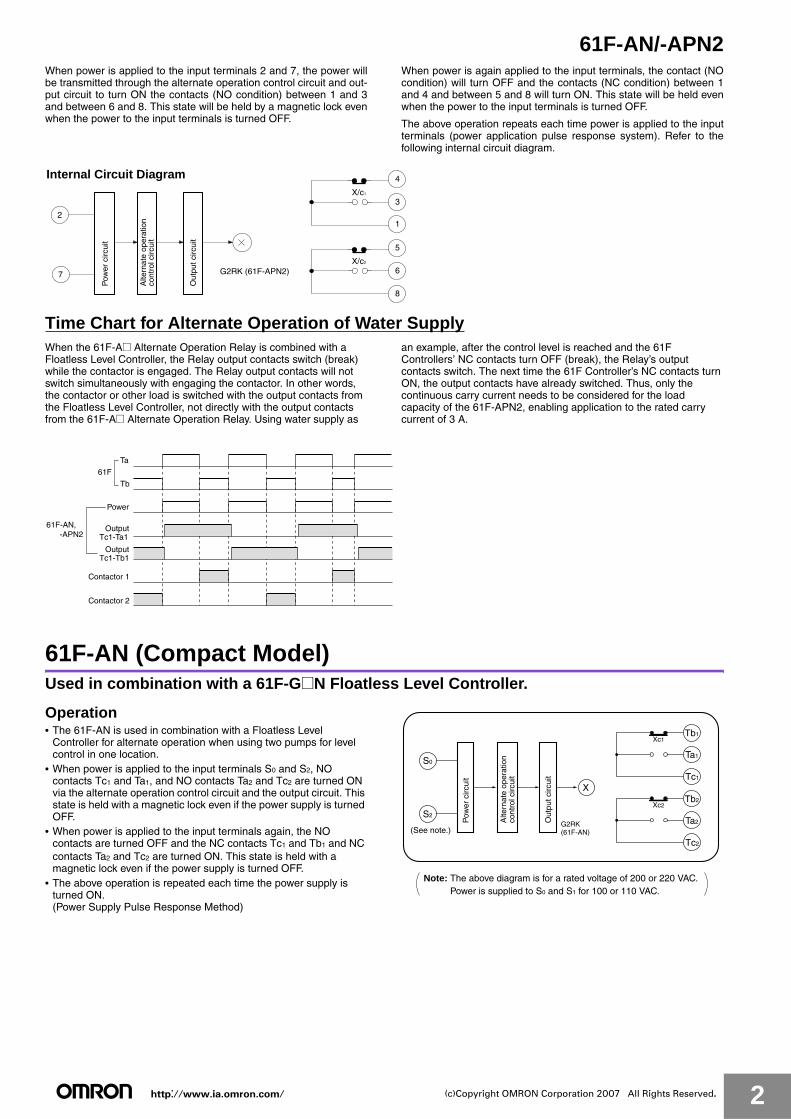
61F-AN/-APN2When power is applied to the input terminals 2 and 7, the power willbe transmitted through the alternate operation control circuit and out-put circuit to turn ON the contacts (NO condition) between 1 and 3and between 6 and 8. This state will be held by a magnetic lock evenwhen the power to the input terminals is turned OFF.
When power is again applied to the input terminals, the contact (NOcondition) will turn OFF and the contacts (NC condition) between 1and 4 and between 5 and 8 will turn ON. This state will be held evenwhen the power to the input terminals is turned OFF.
The above operation repeats each time power is applied to the inputterminals (power application pulse response system). Refer to thefollowing internal circuit diagram.
Time Chart for Alternate Operation of Water SupplyWhen the 61F-A@ Alternate Operation Relay is combined with a Floatless Level Controller, the Relay output contacts switch (break) while the contactor is engaged. The Relay output contacts will not switch simultaneously with engaging the contactor. In other words, the contactor or other load is switched with the output contacts from the Floatless Level Controller, not directly with the output contacts from the 61F-A@ Alternate Operation Relay. Using water supply as
an example, after the control level is reached and the 61F Controllers’ NC contacts turn OFF (break), the Relay’s output contacts switch. The next time the 61F Controller’s NC contacts turn ON, the output contacts have already switched. Thus, only the continuous carry current needs to be considered for the load capacity of the 61F-APN2, enabling application to the rated carry current of 3 A.
61F-AN (Compact Model)Used in combination with a 61F-G@N Floatless Level Controller.
Operation• The 61F-AN is used in combination with a Floatless Level
Controller for alternate operation when using two pumps for level control in one location.
• When power is applied to the input terminals S0 and S2, NO contacts Tc1 and Ta1, and NO contacts Ta2 and Tc2 are turned ON via the alternate operation control circuit and the output circuit. This state is held with a magnetic lock even if the power supply is turned OFF.
• When power is applied to the input terminals again, the NO contacts are turned OFF and the NC contacts Tc1 and Tb1 and NC contacts Ta2 and Tc2 are turned ON. This state is held with a magnetic lock even if the power supply is turned OFF.
• The above operation is repeated each time the power supply is turned ON. (Power Supply Pulse Response Method)
Internal Circuit Diagram
3
4
5
6
1
8
2
7
X/c1
X/c2
Pow
er c
ircui
t
Alte
rnat
e op
erat
ion
cont
rol c
ircui
t
Out
put c
ircui
t
G2RK (61F-APN2)
Ta
Tb
Power
OutputTc1-Ta1
61F
61F-AN, -APN2
OutputTc1-Tb1
Contactor 1
Contactor 2
Xc2
Xc1
X
Pow
er c
ircui
t
Alte
rnat
e op
erat
ion
cont
rol c
ircui
t
Out
put c
ircui
t
G2RK(61F-AN)(See note.)
Tb1
Tc1
Ta1
Tb2
Tc2
Ta2
S0
S2
Note: The above diagram is for a rated voltage of 200 or 220 VAC. Power is supplied to S0 and S1 for 100 or 110 VAC.

http://www.ia.omron.com/ 3(c)Copyright OMRON Corporation 2007 All Rights Reserved.
61F-AN/-APN2Connections (Refer to connection diagram.)
• Connect output terminal Ta in the 61F-GN example (page 4) to input terminal S2 on the 61F-AN.
• Connect coil terminal A on each of the two contactors to the switching contact terminals Ta1 and Tb1 on the 61F-AN.
• Use the switching contact terminals Tb2 and Ta2 on the 61F-AN to control the operation of the two pumps.
• The power supply of the 61F-AN is 100, 110, 200, or 220 VAC. Be sure to use the correct power supply.
61F-APN2 (Compact Plug-in Model)Used in combination with a Floatless Level Controller.
Operation• The 61F-AN2 is used in combination with a Floatless Level
Controller for alternate operation when using two pumps for level control in one location.
• When power is applied to the input terminals 2 and 7, NO contacts 1 and 3, and NO contacts 6 and 8 are turned ON via the alternate operation control circuit and the output circuit. This state is held with a magnetic lock even if the power supply is turned OFF.
• When power is applied to the input terminals again, the NO contacts are turned OFF and the NC contacts 1 and 4 and NC contacts 5 and 8 are turned ON. This state is held with a magnetic lock even if the power supply is turned OFF.
• The above operation is repeated each time the power supply is turned ON. (Power Supply Pulse Response Method)
Note: Refer to Connecting Sockets, Mounting Brackets, DIN Rails for the applicable Sockets.
Connections (Refer to connection diagram.)
• Connect output terminal Ta in the 61F-G example (page 5) to input terminal 2 on the 61F-APN2.
• Connect coil terminal A on each of the two contactors to the switching contact terminals 3 and 4 on the 61F-APN2.
• Use the switching contact terminals 5 and 6 on the 61F-APN2 to control the operation of the two pumps.
• The power supply of the 61F-APN2 is 100, 110, 200, or 220 VAC. Be sure to use the correct power supply.
Output contact betweenTc1-Tb1 and Tc2-Tb2
Power supply voltage
200 ms min.40 ms min.
Output contact betweenTc1-Ta1 and Tc2-Ta2
Xc2
Xc14
3
1
5
6
8
X
2
7
Pow
er c
ircui
t
Alte
rnat
e op
erat
ion
cont
rol c
ircui
t
Out
put c
ircui
t
G2RK(61F-APN2)
Output contact between1-3 and 6-8
Output contact between1-4 and 5-8
Power supply voltagebetween 2-7
200 ms min.40 ms min.

http://www.ia.omron.com/ 4(c)Copyright OMRON Corporation 2007 All Rights Reserved.
61F-AN/-APN2■ Connections
Combining with the 61F-GN
61F-AN
Dimensions:
page 17
Combining with the 61F-GN
Water supply source
MCCB
R S
M1
T
Commercialvoltage 220 VAC
61F-AN
61F-GN
(See note.)
S2
S0
Ta1
Tc1
Tb1
Ta1
Tc1
Tb1
L2
L1
To power source T
X
M2
Contactor 2Contactor 1
P1
A
A
P2
Out
put
circ
uit
Alte
rnat
e op
erat
ion
cont
rol c
ircui
t
PS-3S
E1
E2E3
S1
S2
S0
Tb
Tc
Ta
E3
E2
E1
8 V
UU24 V 61F-11N
Relay Unit
Transformer
U
0 V
110 V
220 V
The relay operation can be monitored if indicators are connected as shown by the dotted line.
Water tank
Pow
erci
rcui
t
Motorprotec-tion relay
Motorprotectionrelay
Note: Be sure to ground the common Electrode E3 (the longest Electrode).
Water Supply
Wastewater tank
Reservoir
MCCB
R S
M1
T
Commercialvoltage 220 VAC
61F-AN
61F-GN
(See note.)
S2
S0
Ta1
Tc1
Tb1
Ta1
Tc1
Tb1
L2
L1
To power source T
X
M2
Contactor 2Contactor 1
P1 P2
A
A
Out
put
circ
uit
Alte
rnat
e op
erat
ion
cont
rol c
ircui
t
S1
S2
S0
Tb
Tc
Ta
E3
E2
E1
8 V
UU24 V 61F-11N
Relay Unit
Transformer
U
0 V
110 V
220 V
PS-3S
E2E3
E1
The relay operation can be monitored if indicators are connected as shown by the dotted line.
Pow
erci
rcui
t
Motorprotec-tion relay
Motorprotectionrelay
Note: Be sure to ground the common Electrode E3 (the longest Electrode).
Drainage
http://www.ia.omron.com/ 5(c)Copyright OMRON Corporation 2007 All Rights Reserved.
61F-AN/-APN2
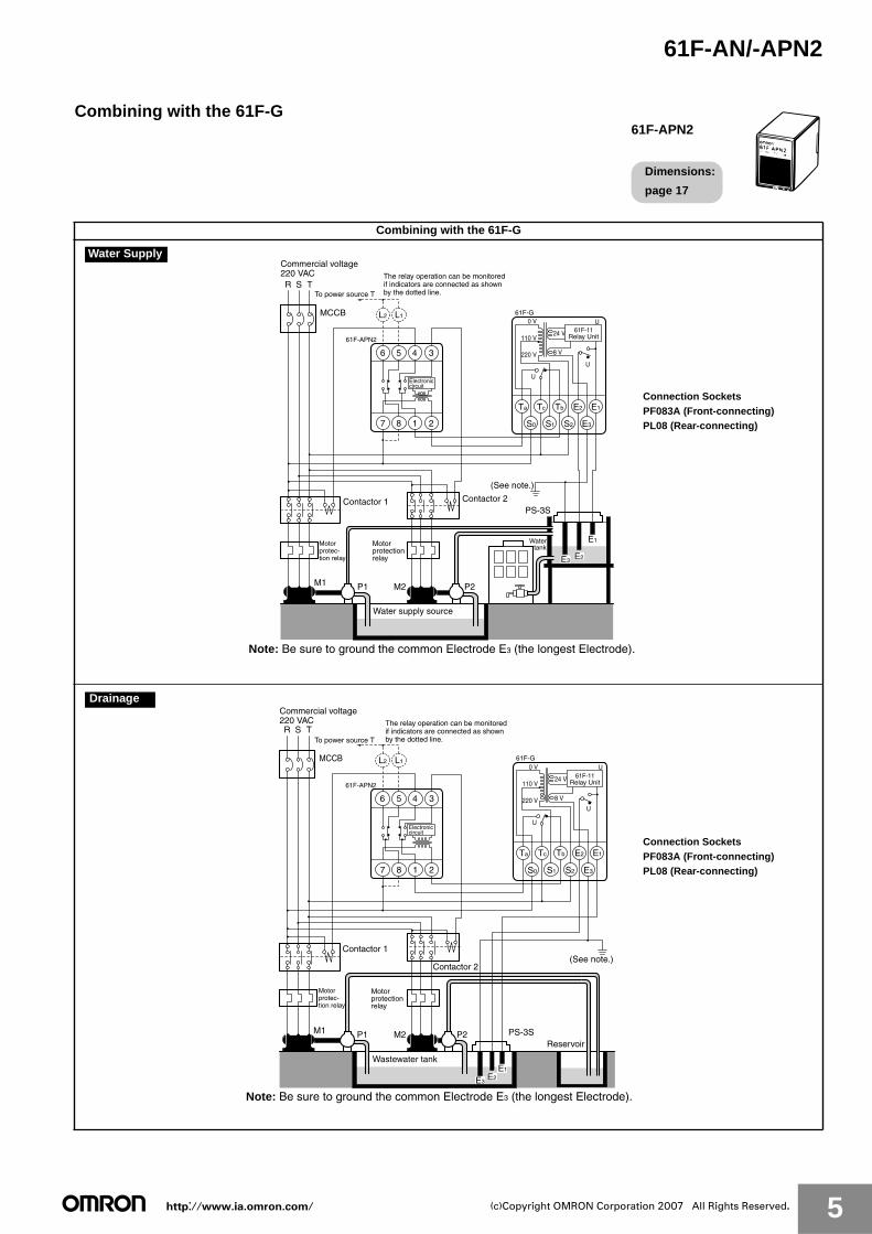
Combining with the 61F-G
61F-APN2
Dimensions:
page 17
Combining with the 61F-G
MCCB
R S T
Commercial voltage 220 VAC
61F-G
(See note.)
TbTcTa E2
S2S1S0 E3
E1
8 V
U
U
U
24 V
0 V
110 V
220 V
61F-11Relay Unit
2187
345
L1
6
L2
To power source T
61F-APN2
Water supply source
M1 M2
Contactor 2Contactor 1
P1 P2
PS-3S
E1
E2E3
The relay operation can be monitored if indicators are connected as shown by the dotted line.
Electroniccircuit
Water tank
Motorprotec-tion relay
Motorprotectionrelay
Note: Be sure to ground the common Electrode E3 (the longest Electrode).
Connection SocketsPF083A (Front-connecting)PL08 (Rear-connecting)
Water Supply
MCCB
R S T
Commercial voltage 220 VAC
61F-G
(See note.)
TbTcTa E2
S2S1S0 E3
E1
8 V
U
U
U
24 V
0 V
110 V
220 V
61F-11Relay Unit
2187
345
L1
6
L2
To power source T
61F-APN2
Wastewater tank
Reservoir
M1 M2
Contactor 2
Contactor 1
P1 P2
E2E3
PS-3S
E1
The relay operation can be monitored if indicators are connected as shown by the dotted line.
Electroniccircuit
Motorprotectionrelay
Motorprotec-tion relay
Note: Be sure to ground the common Electrode E3 (the longest Electrode).
Connection SocketsPF083A (Front-connecting)PL08 (Rear-connecting)
Drainage
http://www.ia.omron.com/ 6(c)Copyright OMRON Corporation 2007 All Rights Reserved.
61F-AN/-APN2
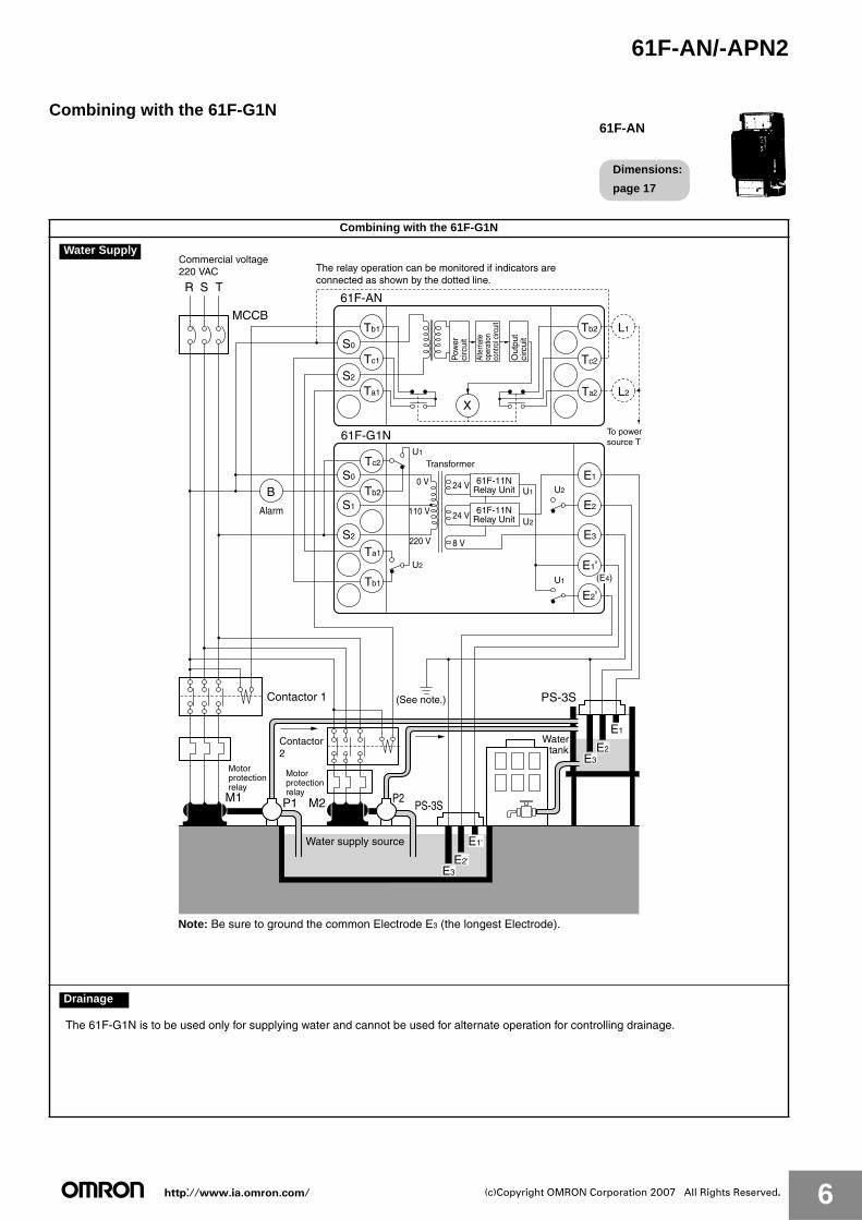
Combining with the 61F-G1N
61F-AN
Dimensions:
page 17
Combining with the 61F-G1N
Water supply source
MCCB
R S
M1
T
Commercial voltage 220 VAC
61F-G1N
61F-AN
(See note.)
Alarm
S0
S1
S2
E1
E2
E3
E1'
E2'
Tc2
Tb2
Ta1
Tb1
S2
S0
Ta1
Tc1
Tb1
Ta2
Tc2
Tb2
L2
L1
X
P1
Contactor 1
M2 P2
Out
put
circ
uit
Alte
rnat
e op
erat
ion
cont
rol c
ircui
t
PS-3S
PS-3S
E1
E2E3
E2'E3
E1'
B
Transformer
8 V
U1 (E4)
U1
U2
U2
U2
U124 V
24 V
0 V
110 V
220 V
61F-11NRelay Unit
61F-11NRelay Unit
The relay operation can be monitored if indicators are connected as shown by the dotted line.
Pow
erci
rcui
t
Contactor2
Water tank
To power source T
Motorprotectionrelay
Motorprotectionrelay
Note: Be sure to ground the common Electrode E3 (the longest Electrode).
Water Supply
The 61F-G1N is to be used only for supplying water and cannot be used for alternate operation for controlling drainage.
Drainage
http://www.ia.omron.com/ 7(c)Copyright OMRON Corporation 2007 All Rights Reserved.
61F-AN/-APN2
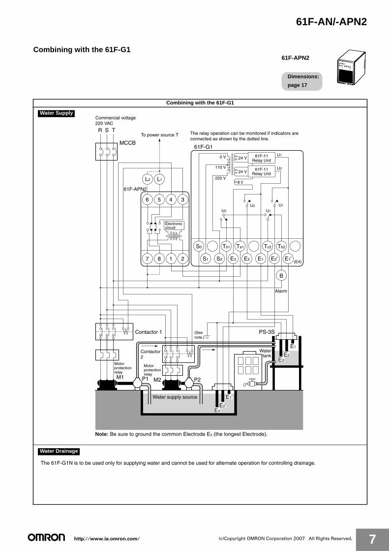
Combining with the 61F-G1
61F-APN2
Dimensions:
page 17
Combining with the 61F-G1
Water supply source
MCCB
R S
M1
T
Commercial voltage 220 VAC
(Seenote.)
P1
Contactor 1
M2 P2
PS-3S
E1
E2E3
E2'E3
E1'
61F-G1
S0 Tb1 Ta1 Tc2 Tb2
S1 S22187
3
L1L2
456
E3 E2 E1 E2' E1'(E4)
220 V
110 V
0 V 24 V
24 V
To power source T
61F-APN2
B
U1
U1
U1U2
U2
U2
8 V
61F-11Relay Unit
61F-11Relay Unit
The relay operation can be monitored if indicators are connected as shown by the dotted line.
Electroniccircuit
Alarm
Contactor2
Water tank
Motorprotectionrelay
Motorprotectionrelay
Note: Be sure to ground the common Electrode E3 (the longest Electrode).
Water Supply
The 61F-G1N is to be used only for supplying water and cannot be used for alternate operation for controlling drainage.
Water Drainage
http://www.ia.omron.com/ 8(c)Copyright OMRON Corporation 2007 All Rights Reserved.
61F-AN/-APN2
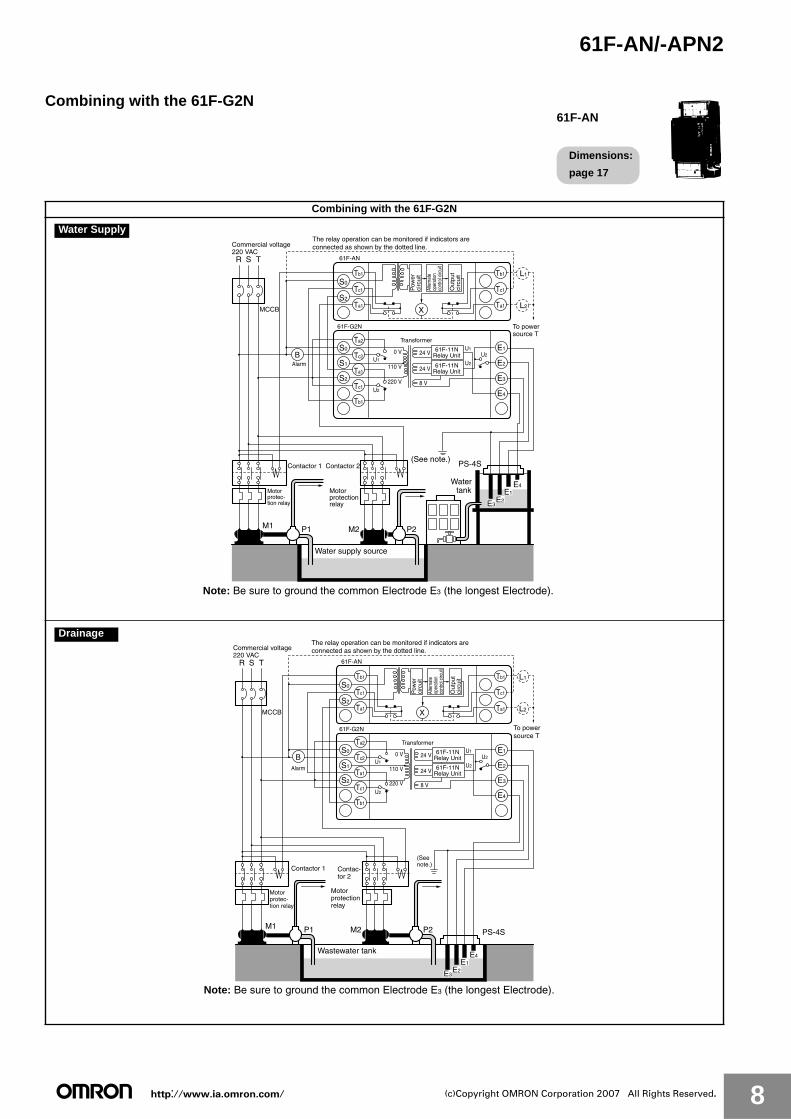
Combining with the 61F-G2N
61F-AN
Dimensions:
page 17
Combining with the 61F-G2N
Water supply source
MCCB
R S
M1
T
Commercial voltage 220 VAC
61F-G2N
61F-AN
(See note.)
S0
S1
S2
E1
E2
E3
E4
S2
S0
Ta1
Ta2
Tc2
Ta1
Tc1
Tb1
Tc1
Tb1
Ta1
Tc1
Tb1
L2
L1
X
M2
Contactor 2Contactor 1
P1 P2
Out
put
circ
uit
Alte
rnat
e op
erat
ion
cont
rol c
ircui
t
Transformer
8 V
U1U2
U1
U2
24 V
24 V
0 V
110 V
220 V
Alarm
61F-11NRelay Unit
U2
B
PS-4S
E4
E2E3
E1
The relay operation can be monitored if indicators are connected as shown by the dotted line.
Pow
erci
rcui
t
61F-11NRelay Unit
Water tank
To power source T
Motorprotec-tion relay
Motorprotectionrelay
Note: Be sure to ground the common Electrode E3 (the longest Electrode).
Water Supply
Wastewater tank
MCCB
R S
M1
T
Commercial voltage 220 VAC
61F-G2N
61F-AN
(Seenote.)
S0
S1
S2
E1
E2
E3
E4
S2
S0
Ta1
Ta2
Tc2
Ta1
Tc1
Tb1
Tc1
Tb1
Ta1
Tc1
Tb1
L2
L1
X
M2
Contactor 1
P1 P2
Out
put
circ
uit
Alte
rnat
e op
erat
ion
cont
rol c
ircui
t
PS-4S
E4
E2E3
E1
Transformer
8 V
U1U2
U1
U2
24 V
24 V
0 V
110 V
220 V
Alarm
61F-11NRelay Unit
U2
B
The relay operation can be monitored if indicators are connected as shown by the dotted line.
Pow
erci
rcui
t
61F-11NRelay Unit
Contac-tor 2
To power source T
Motorprotec-tion relay
Motorprotectionrelay
Note: Be sure to ground the common Electrode E3 (the longest Electrode).
Drainage
http://www.ia.omron.com/ 9(c)Copyright OMRON Corporation 2007 All Rights Reserved.
61F-AN/-APN2
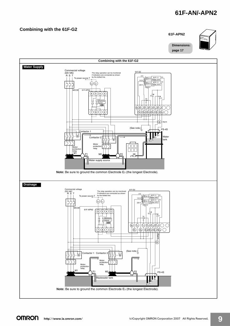
Combining with the 61F-G2
61F-APN2
Dimensions:
page 17
Combining with the 61F-G2
Water supply source
MCCB
R S
M1
T
Commercial voltage 220 VAC
M2
Contactor 2
Contactor 1
P1 P2
PS-4S
E4
E2E3
E1
61F-G2
(See note.)
S2 E3 E2 E4E1S1
S0
8 V
U2
U2
U1
U1
U2
24 V
24 V
0 V
110 V
220 V
61F-11Relay Unit
B
2187
345
L1
6
L2
To power source T
61F-APN2
Ta1 Tc1 Tb1 Ta2 Tc2
The relay operation can be monitored if indicators are connected as shown by the dotted line.
Electroniccircuit
61F-11Relay Unit
Alarm
Water tank
Motorprotectionrelay
Motorprotectionrelay
Note: Be sure to ground the common Electrode E3 (the longest Electrode).
Water Supply
Wastewater tank
MCCB
R S
M1
T
Commercial voltage 220 VAC
M2
Contactor 2Contactor 1
P1 P2 PS-4S
E4
E2E3
E1
61F-G2
(See note.)
S2 E3 E2 E4E1S1
S0
8 V
U2
U2
U1
U1
U2
24 V
24 V
0 V
110 V
220 V
B
Alarm
2187
345
L1
6
L2
To power source T
61F-APN2
Ta1 Tc1 Tb1 Ta2 Tc2
The relay operation can be monitored if indicators are connected as shown by the dotted line.
Electroniccircuit
61F-11Relay Unit
61F-11Relay Unit
Motorprotectionrelay
Motorprotectionrelay
Note: Be sure to ground the common Electrode E3 (the longest Electrode).
Drainage
http://www.ia.omron.com/ 10(c)Copyright OMRON Corporation 2007 All Rights Reserved.
61F-AN/-APN2
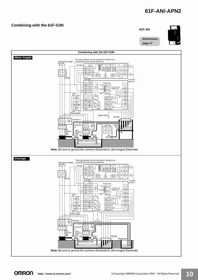
Combining with the 61F-G3N
61F-AN
Dimensions:
page 17
Combining with the 61F-G3N
Water supply source
MCCB
R S
M1
T
Commercial voltage 220 VAC
61F-G3N
61F-AN
(See note.)
S0
Ta
Tc
Tb
B1
B2
S1
S2
LH
Lc
LL
E1
E2
E3
E4
E5
PL
B
PL
S2
S0
Ta1
Tc1
Tb1
Ta1
Tc1
Tb1
L2
L1
Power supply
X
M2
Contactor 1
Contactor2
P1 P2
Out
put
circ
uit
Alte
rnat
e op
erat
ion
cont
rol c
ircui
t
PS-5S
E1
E2E3E4
E5
Transformer
8 V
U3
U1
U3
U1
U2
U2
U1
U2
U3
Lamp
Lamp
Alarm Bell
24 V
24 V
0 V
110 V
220 V
61F-11NRelay Unit
To 61F-11N Relay Unit
The relay operation can be monitored if indicators are connected as shown by the dotted line.
To power source T
Pow
erci
rcui
t61F-11N
Relay Unit
61F-11NRelay Unit
Upperlimit
Lower limit
Motorprotectionrelay
Motorprotectionrelay
Water tank
Note: Be sure to ground the common Electrode E3 (the longest Electrode).
Water Supply
Wastewater tank
Reservoir
MCCB
R S
M1
T
61F-G3N
61F-AN
(See note.)
S0
Ta
Tc
Tb
B1
B2
S1
S2
LH
Lc
LL
E1
E2
E3
E4
E5
PL
B
PL
S2
S0
Ta1
Tc1
Tb1
Ta1
Tc1
Tb1
L2
L1
X
P1
Contactor2
Contactor 1
M2 P2
Out
put
circ
uit
Alte
rnat
eop
erat
ion
cont
rol c
ircui
t
Transformer
8 V
U3
U1
U3
U1
U2
U2
U1
U2
U3
Lamp
Lamp
Alarm Bell
24 V
24 V
0 V
110 V
220 V
E1E2
E3E4E5
PS-5S
Commercial voltage 220 VAC
The relay operation can be monitored if indicators are connected as shown by the dotted line.
Pow
erci
rcui
t
To power source T
To 61F-11N Relay Unit
61F-11NRelay Unit
61F-11NRelay Unit
61F-11NRelay Unit
Power supply
Upperlimit
Lower limit
Motorprotectionrelay
Motorprotectionrelay
Note: Be sure to ground the common Electrode E3 (the longest Electrode).
Drainage

http://www.ia.omron.com/ 11(c)Copyright OMRON Corporation 2007 All Rights Reserved.
61F-AN/-APN2
Combining with the 61F-G3
61F-APN2
Dimensions:
page 17
Combining with the 61F-G3
Water supply source
MCCB
R S
M1
T
Commercial voltage 220 VAC
61F-G3
(See note.)
S1
Tc Tb B1 E1LcB2 E3
S2 E2LLLH E4S0
PL
Ta E5
P1
Contactor2
Contactor 1
M2 P2
PS-5S
E1
E2E3E4
E5
8 V
U2 U2U1
U1
U3 U3
U1
U2
Lamp
24 V
24 V
0 V
110 V
220 VU3
24 V
PL
Lamp
B
2187
345
L1
6
L2
To power source T
61F-APN2
The relay operation can be monitored if indicators are connected as shown by the dotted line.
Electroniccircuit
61F-11NRelay Unit
61F-11NRelay Unit
61F-11NRelay Unit
Alarm Bell
Power supply
Upperlimit
Lower limit
Motorprotectionrelay
Motorprotectionrelay
Water tank
Note: Be sure to ground the common Electrode E3 (the longest Electrode).
Water Supply
Wastewater tankReservoir
MCCB
R S
M1
T
61F-G3
S1
Tc Tb B1 E1LcB2 E3
S2 E2LLLH E4S0
PL
Ta E5
P1 M2 P2
8 V
U2 U2U1
U1
U3 U3
U1
U2
Lamp
24 V
24 V
0 V
110 V
220 VU3
24 V
PL
Lamp
B
2187
345
L1
6
L2
61F-APN2
E1E2
E3E4E5
PS-5S
Commercial voltage 220 VAC
To power source T
The relay operation can be monitored if indicators are connected as shown by the dotted line. 61F-11N
Relay Unit
61F-11NRelay Unit
61F-11NRelay Unit
Electroniccircuit
(Seenote.)
Alarm Bell
Power supply
Upperlimit
Lower limit
Contactor2
Contactor 1
Motorprotectionrelay
Motorprotectionrelay
Note: Be sure to ground the common Electrode E3 (the longest Electrode).
Drainage

http://www.ia.omron.com/ 12(c)Copyright OMRON Corporation 2007 All Rights Reserved.
61F-AN/-APN2
Combining with the 61F-G4N
Alternate Operation Relay61F-AN
Dimensions:
page 17
Combining with the 61F-G4N
Contactor 1
Water supply source
MCCB
R S
M1
T
Commercialvoltage 220 VAC
61F-G4N
61F-AN
PS-5S
PS-4S
E1
BL1
BH2
BL2
LH1
LL1
LL2
LH2
Tc
Tc2
B
TA
S0
S1
S2
BH1
BL1
BH2
BL2
LH1
LL1
LL2
LH2
BH1E4
E8
E2
E1
E3
E5
E6
E7
E8
(See note.)
S2
S0
Ta1
Tc1
Tb1
Ta2
Tc2
Tb2
Ta2
Tb2
61F-11NRelay Unit
61F-11NRelay Unit
61F-11NRelay Unit
61F-11NRelay Unit
61F-11NRelay Unit
220 V
U4
U3
U2
U5
U2
U4
U5
U1
U1
U3
U5
U2
X
U4
U1
U3
X
X
110 VMY3 Relay
0 VTransformer
8 V
24 V
24 V
X
X
P1
Contactor 2
M2 P2
Out
put
circ
uit
Alte
rnat
e op
erat
ion
cont
rol c
ircui
t
E4
E5
E2
E7E8
E6
E3E8
The relay operation can be monitored if indicators are connected as shown by the dotted line.
To power source T
Pow
erci
rcui
tTo 61F-11N Relay Unit
Elevated tank repletion
Water supply source upper limitWater supply source lower limit
Elevated tank water shortage
Elevated tank repletion
Water supply source upper limitWater supply source lower limit
Elevated tank water shortage
Motorprotectionrelay
Motorprotectionrelay
Water tank
Note: Be sure to ground the common Electrode E3 (the longest Electrode).
Water Supply
The 61F-G4N is to be used only for supplying water and cannot be used alternately for controlling drainage.
Drainage

http://www.ia.omron.com/ 13(c)Copyright OMRON Corporation 2007 All Rights Reserved.
61F-AN/-APN2
Combining with the 61F-G4
Alternate Operation Relay61F-APN2
Dimensions:
page 17
Combining with the 61F-G4
61F-G4
U2U3
U2
U5
U1
U2
U3
U4
MK3PRelay
U4XU5U1XU3U4XU1 U5
LL1
2187
345
L1
6
L2
LL2 LH1
X
LH2 BL1 BL2 BH1 BH2
LL1 LL2 LH1 LH2 BL1 BL2 BH1 BH2
E4 E3 E2 E1
S0 S1 S2 TC TC2 B TA E8 E7 E6 E5
200 V
100 V
0 V24 V
24 V
220 V
110 V
0 V 24 V
24 V
24 V
Electroniccircuit
Contactor 1
Water supply source
MCCB
R S
M1
T
To power source T
61F-APN2
PS-5S
PS-4S
E4
E1
(See note.)
P1
Contactor 2
M2 P2
8 V
61F-1Relay Unit
61F-1Relay Unit
61F-1Relay Unit
61F-1Relay Unit
61F-1Relay Unit
E7E8
E2
E3E8
E5
E6
Commercialvoltage 220 VAC
Elevated tank water shortage
Elevated tankrepletion
Water supplysourcelower limit
Water supplysourceupper limit
Elevated tank water shortage
Elevated tankrepletion
Water supplysourcelower limit
Water supplysourceupper limit
Motorprotectionrelay
Motorprotectionrelay
Water tank
Note: Be sure to ground the common Electrode E3 (the longest Electrode).
Water Supply
The 61F-G4N is to be used only for supplying water and cannot be used alternately for controlling drainage.
Drainage
http://www.ia.omron.com/ 14(c)Copyright OMRON Corporation 2007 All Rights Reserved.
61F-AN/-APN2
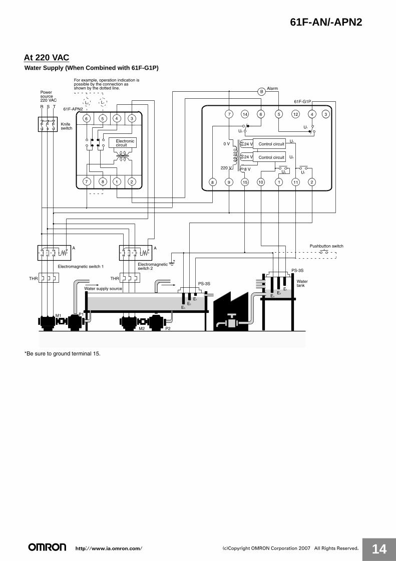
At 220 VACWater Supply (When Combined with 61F-G1P)
*Be sure to ground terminal 15.
P1
Power source220 VAC
R S T
Water supply source
M1
Electromagnetic switch 1
4 356
1 287
L1L2
Water tank
Electroniccircuit
61F-APN2
For example, operation indication is possible by the connection as shown by the dotted line.
P2M2
E2
E3
E1
Control circuit
Control circuit
E3
E2
E1
24 V
24 V0 V
220 V 8 V
Alarm
8 9 15 1 11 2
Pushbutton switch
Electromagneticswitch 2
A A
Knife switch
14 12 345
U2 U1
B
U1
61F-G1P
7 6
10
U1
U2
U2
*
THR THR
PS-3S
PS-3S

http://www.ia.omron.com/ 15(c)Copyright OMRON Corporation 2007 All Rights Reserved.
61F-AN/-APN2
Water Supply (When Combined with 61F-GP-N)
*Be sure to ground terminal 4.
P1
E2
E3
E1
Knife switch
Power source220 VAC
R S T
0 V
220 V8 V
24 V Control circuit
U
M2P2
Water supply source
M1
4 356
1 287
L1L2
10 11 1 2
Water tank
61F-GP-N
Electroniccircuit
61F-APN
For example, operation indication is possible by the connection as shown by the dotted line.
Electromagnetic switch 1 Electromagnetic switch 2
A A
9 3
8
U
67
4
5
Water supply source
*
THR THR PS-3S
U

http://www.ia.omron.com/ 16(c)Copyright OMRON Corporation 2007 All Rights Reserved.
61F-AN/-APN2Water Drainage (When Combined with 61F-G2P)
*Be sure to ground terminal 15.
P1
Power source220 VAC R S T
Water supply source
M1
Electromagnetic switch 1
4 356
1 287
L1L2
Electroniccircuit
61F-ANP2
Knife switch
For example, operation indication is possible by the connection as shown by the dotted line.
P2M2
E1
E3
E4
Electromagnetic switch 2
Control circuit
24 V
24 V0 V
220 V8 V
Alarm
8 15 10 119 1
E2
A A
14 6 127
2
4 3
U1U2
61F-G2P
U1
U2
U2
5
B
*
Control circuit
THRTHR
PS-4S

http://www.ia.omron.com/ 17(c)Copyright OMRON Corporation 2007 All Rights Reserved.
61F-AN/-APN2
DimensionsNote: All units are in millimeters unless otherwise indicated.
■ Safety PrecautionsRefer to Safety Precautions for All Level Controllers.
5
3
5
100 70
10 5
40450
11
50
65
54
35.4
4 min.
3.4
10
4 min.
90
39
56
9 Twelve, M3.5 sems screws
Terminal cover
32
6011
14142542
(See note.)
61F-AN
Note: Dimensions are with the DIN rail mounting (sliding) bracket attached.
49.4
38 70
84
61F-APN2
PF083A
91
61F-APN2
In the interest of product improvement, specifications are subject to change without notice.
ALL DIMENSIONS SHOWN ARE IN MILLIMETERS.
To convert millimeters into inches, multiply by 0.03937. To convert grams into ounces, multiply by 0.03527.

http://www.ia.omron.com/ C-1(c)Copyright OMRON Corporation 2007 All Rights Reserved.
Safety Precautions for Floatless Level Controllers
!WARNING
Precautions for Safe UseDo not use the Controller in locations subject to explosive or combustible dust, combustible gas, flammable vapors, corrosive gas, excessive dust, salt water spray, or water drops.
Precautions for Correct Use● Operating Environment
• Use and store the Controller within the rated ambient operating temperature, ambient operating humidity, and storage temperature ranges specified for individual models.
• Use the Controller according to the characteristics specified for individual models for vibration, shock, exposure to water, and exposure to oil.
• Install the Controller as far as possible from devices that generate strong high-frequency noise (such as high frequency welders or sewing machines).
● Tighten Terminal Screws to the Specified TorqueWhen fitting crimping terminals to terminal screws, use a tightening torque of between 0.45 and 0.6 N·m
● Use a Power Supply with Minimal Voltage Fluctuation
Avoid connection to a power supply with a voltage fluctuation greater than or equal to +10% or 15%.
● Consider the Ambient Temperature
Do not install the Controller where it may be exposed to a temperature of 55 C or higher or a humidity of 85% or higher. In particular, install the Controller away from heat-generating equipment incorporating coils or windings. Do not use the Controller outdoors or in locations subject to high humidity, corrosive gases, or direct sunlight.
● Avoid Vibration and Shocks
Do not subject the Controller to vibration or shocks which can cause chattering problems. Do not install the Controller near contactors that generate severe shocks while the contactors are in operation.
● Do Not Test with a Megaohmmeter
During insulation resistance measurements, never apply the megaohmmeter across the Electrode terminals.
● Use Self-holding Electrodes
• Use Self-holding (E2) Electrodes when contactor open/close control is carried out. If E1 Electrodes are used, ripples on the liquid surface can cause incorrect contactor operation and damage to the contacts.
• Be sure to turn OFF the power supply before replacing the plug-in models.
● Short Wiring in Electrode Circuit
• Keep the wires connecting the Controller to Electrode Holders as short as possible. If long leads are used, the floating capacity of the leads, and abnormal surges or noise in the Electrode circuit can cause malfunctions.
• The thicker the cables, the shorter the permitted wiring length. The length of the cable connecting the Controller and Electrode is specified in the Controller datasheet as a guideline assuming that a 600-V VCT 0.75-mm2, 3-core cabtire cable is used. Test results indicate that the actual wiring length using VCT 3.5-mm2, 3-core cable laid over the ground is 50% of the specified length for
general-purpose applications and 80% of the specified length for long-distance applications. When selecting cable specifications, remember that the wiring length is further decreased for underground cables and larger diameter cables because of the increased floating capacity with the ground.
● Keep Power Cables Separate from the Electrode Circuit
Do not pass the leads for the Electrode circuit through the same duct, or near to, high-tension cables or power cables. This can cause noise which leads to malfunctions.
● Ground Correctly
Ground the common Electrode terminal to reduce the effects of noise.
● Use a Surge Suppressor
Connect a 61F-03B(-04B) Surge Suppressor with the Controller’s Electrode terminals to protect the circuit from surges. This is particularly important in lightning-prone areas. To further improve protection, install a commercial surge suppressor in the power supply to eliminate surges in the power system.(Refer to 61F-03B/-04B.)
● Consider the Response Times
The Controller requires a response time not exceeding 80 ms for operation or 160 ms for reset. Take these response times into account in cases where precise sequence control is required.
● Consider the Liquids to Be Controlled
• The Controller cannot be used for any liquid that has almost no conductivity such as sewage containing oil.
• The Controller cannot be used for any flammable liquid such as gasoline, kerosene, or heavy oil.
● Do Not Share Electrodes
Do not connect a single Electrode to more than one Controller. If the phases of the 8-VAC Electrode-circuit power supplies are opposite to each other, as shown in Fig. 1, an internal close circuit (return circuit) is created (indicated by the arrows). The Controller may malfunction regardless of the liquid level when the Controller power is turned ON. This problem can be overcome by matching the power supply phases, as shown in Fig. 2, but in this configuration the internal impedance of the Controller calculated from the Electrode will be approximately half as large as the internal impedance of a single Controller. Maintain sufficient clearance between Electrodes connected to separate Controllers so that they do not interfere with each other. Common leads, however, can be connected to the ground Electrode.
Do not touch the terminals while power is being supplied. Doing so may occasionally result in electric shock.
Do not attempt to disassemble, repair, or modify the product while the power is being supplied. Doing so may occasionally result in electric shock.
Fig. 2 Match PhasesT S
S0 S2
R61F
S0 S2
61F
8 VAC8 VAC
Fig. 1 Internal Closed Circuit
X X

http://www.ia.omron.com/ C-2(c)Copyright OMRON Corporation 2007 All Rights Reserved.
In the interest of product improvement, specifications are subject to change without notice.
ALL DIMENSIONS SHOWN ARE IN MILLIMETERS.
To convert millimeters into inches, multiply by 0.03937. To convert grams into ounces, multiply by 0.03527.

http://www.ia.omron.com/ C-3(c)Copyright OMRON Corporation 2007 All Rights Reserved.
Safety Precautions for All Level ControllersRefer to the Safety Precautions section for each product for specific precautions applicable to that product.
!WARNINGDo not touch the terminals while power is being supplied.Doing so may possibly result in electric shock.
Do not attempt to disassemble, repair, or modify the product while power is being supplied. Doing so may occasionally result in electric shock.
■ Precautions for Safe UseIn order to ensure safe operation, be sure to observe the following points.
1. Use a power supply voltage within the specified range.2. Do not use the Controller in locations subject to flammable gases
or objects.3. Insert the Socket until it securely clicks into place.4. Do not short the load connected to the output terminals.5. Do not connect the power supply in reverse.6. Do not use the Controller in locations subject to explosive or
combustible dust, combustible gas, flammable vapors, corrosive gas, excessive dust, salt water spray, or water drops.
■ Precautions for Correct UseFor details, refer to Technical Guide for Level Controllers.
In the interest of product improvement, specifications are subject to change without notice.

2007.3
OMRON CorporationIndustrial Automation Company
http://www.ia.omron.com/ (c)Copyright OMRON Corporation 2007 All Rights Reserved.
In the interest of product improvement, specifications are subject to change without notice.
Read and Understand This Catalog
Please read and understand this catalog before purchasing the products. Please consult your OMRON representative if you have any questions or comments.
Warranty and Limitations of Liability
WARRANTYOMRON's exclusive warranty is that the products are free from defects in materials and workmanship for a period of one year (or other period if specifi ed) from date of sale by OMRON.
OMRON MAKES NO WARRANTY OR REPRESENTATION, EXPRESS OR IMPLIED, REGARDING NON-INFRINGEMENT, MERCHANTABILITY, OR FITNESS FOR PARTICULAR PURPOSE OF THE PRODUCTS. ANY BUYER OR USER ACKNOWLEDGES THAT THE BUYER OR USER ALONE HAS DETERMINED THAT THE PRODUCTS WILL SUITABLY MEET THE REQUIREMENTS OF THEIR INTENDED USE. OMRON DISCLAIMS ALL OTHER WARRANTIES, EXPRESS OR IMPLIED.
LIMITATIONS OF LIABILITYOMRON SHALL NOT BE RESPONSIBLE FOR SPECIAL, INDIRECT, OR CONSEQUENTIAL DAMAGES, LOSS OF PROFITS, OR COMMERCIAL LOSS IN ANY WAY CONNECTED WITH THE PRODUCTS, WHETHER SUCH CLAIM IS BASED ON CONTRACT, WARRANTY, NEGLIGENCE, OR STRICT LIABILITY.
In no event shall responsibility of OMRON for any act exceed the individual price of the product on which liability is asserted.
IN NO EVENT SHALL OMRON BE RESPONSIBLE FOR WARRANTY, REPAIR, OR OTHER CLAIMS REGARDING THE PRODUCTS UNLESS OMRON'S ANALYSIS CONFIRMS THAT THE PRODUCTS WERE PROPERLY HANDLED, STORED, INSTALLED, AND MAINTAINED AND NOT SUBJECT TO CONTAMINATION, ABUSE, MISUSE, OR INAPPROPRIATE MODIFICATION OR REPAIR.
Application Considerations
SUITABILITY FOR USEOMRON shall not be responsible for conformity with any standards, codes, or regulations that apply to the combination of products in the customer's application or use of the product. At the customer's request, OMRON will provide applicable third party certifi cation documents identifying ratings and limitations of use that apply to the products. This information by itself is not suffi cient for a complete determination of the suitability of the products in combination with the end product, machine, system, or other application or use.
The following are some examples of applications for which particular attention must be given. This is not intended to be an exhaustive list of all possible uses of the products, nor is it intended to imply that the uses listed may be suitable for the products:
• Outdoor use, uses involving potential chemical contamination or electrical interference, or conditions or uses not described in this catalog.
• Nuclear energy control systems, combustion systems, railroad systems, aviation systems, medical equipment, amusement machines, vehicles, safety equipment, and installations subject to separate industry or government regulations.
• Systems, machines, and equipment that could present a risk to life or property.
Please know and observe all prohibitions of use applicable to the products.
NEVER USE THE PRODUCTS FOR AN APPLICATION INVOLVING SERIOUS RISK TO LIFE OR PROPERTY WITHOUT ENSURING THAT THE SYSTEM AS A WHOLE HAS BEEN DESIGNED TO ADDRESS THE RISKS, AND THAT THE OMRON PRODUCT IS PROPERLY RATED AND INSTALLED FOR THE INTENDED USE WITHIN THE OVERALL EQUIPMENT OR SYSTEM.
Disclaimers
CHANGE IN SPECIFICATIONSProduct specifi cations and accessories may be changed at any time based on improvements and other reasons.
It is our practice to change model numbers when published ratings or features are changed, or when signifi cant construction changes are made. However, some specifi cations of the product may be changed without any notice. When in doubt, special model numbers may be assigned to fi x or establish key specifi cations for your application on your request. Please consult with your OMRON representative at any time to confi rm actual specifi cations of purchased product.
DIMENSIONS AND WEIGHTSDimensions and weights are nominal and are not to be used for manufacturing purposes, even when tolerances are shown.
ERRORS AND OMISSIONSThe information in this catalog has been carefully checked and is believed to be accurate; however, no responsibility is assumed for clerical, typographical, or proofreading errors, or omissions.
PERFORMANCE DATA Performance data given in this catalog is provided as a guide for the user in determining suitability and does not constitute a warranty. It may represent the result of OMRON’s test conditions, and the users must correlate it to actual application requirements. Actual performance is subject to the OMRON Warranty and Limitations of Liability.
PROGRAMMABLE PRODUCTSOMRON shall not be responsible for the user's programming of a programmable product, or any consequence thereof.
COPYRIGHT AND COPY PERMISSIONThis catalog shall not be copied for sales or promotions without permission.
This catalog is protected by copyright and is intended solely for use in conjunction with the product. Please notify us before copying or reproducing this catalog in any manner, for any other purpose. If copying or transmitting this catalog to another, please copy or transmit it in its entirety.


