
Alcatel-Lucent 7705SERVICE AGGREGATION ROUTER | RELEASE 1.1S A R - F C H A S S I S I N S T A L L A T I O N G U I D E
Alcatel-Lucent ProprietaryThis document contains proprietary information of Alcatel-Lucent and is not to be disclosedor used except in accordance with applicable agreements.Copyright 2008 © Alcatel-Lucent. All rights reserved.
When printed by Alcatel-Lucent, this document is printed on recycled paper.
Alcatel-Lucent assumes no responsibility for the accuracy of the information presented, which is subject to change without notice.
Alcatel, Lucent, Alcatel-Lucent and the Alcatel-Lucent logo are trademarks of Alcatel-Lucent. All other trademarks are the property of their respective owners.
Copyright 2008 Alcatel-Lucent.All rights reserved.
Disclaimers
Alcatel-Lucent products are intended for commercial uses. Without the appropriate network design engineering, they must not be sold, licensed or otherwise distributed for use in any hazardous environments requiring fail-safe performance, such as in the operation of nuclear facilities, aircraft navigation or communication systems, air traffic control, direct life-support machines, or weapons systems, in which the failure of products could lead directly to death, personal injury, or severe physical or environmental damage. The customer hereby agrees that the use, sale, license or other distribution of the products for any such application without the prior written consent of Alcatel-Lucent, shall be at the customer's sole risk. The customer hereby agrees to defend and hold Alcatel-Lucent harmless from any claims for loss, cost, damage, expense or liability that may arise out of or in connection with the use, sale, license or other distribution of the products in such applications.
This document may contain information regarding the use and installation of non-Alcatel-Lucent products. Please note that this information is provided as a courtesy to assist you. While Alcatel-Lucent tries to ensure that this information accurately reflects information provided by the supplier, please refer to the materials provided with any non-Alcatel-Lucent product and contact the supplier for confirmation. Alcatel-Lucent assumes no responsibility or liability for incorrect or incomplete information provided about non-Alcatel-Lucent products.
However, this does not constitute a representation or warranty. The warranties provided for Alcatel-Lucent products, if any, are set forth in contractual documentation entered into by Alcatel-Lucent and its customers.
This document was originally written in English. If there is any conflict or inconsistency between the English version and any other version of a document, the English version shall prevail.
7705 SAR-F Installation Guide Page 3
Table of Contents
Preface . . . . . . . . . . . . . . . . . . . . . . . . . . . . . . . . . . . . . . . . . . . . . . . . . . . . . . . . . . . . . . . . . . . . . . . . . 19
Mandatory Regulations . . . . . . . . . . . . . . . . . . . . . . . . . . . . . . . . . . . . . . . . . . . . . . . . . . . . . . . . . . . . 23List of Terms . . . . . . . . . . . . . . . . . . . . . . . . . . . . . . . . . . . . . . . . . . . . . . . . . . . . . . . . . . . . . . . . . . . . . . . . . . . 24General Requirements . . . . . . . . . . . . . . . . . . . . . . . . . . . . . . . . . . . . . . . . . . . . . . . . . . . . . . . . . . . . . . . . . . . 25Canada Regulations . . . . . . . . . . . . . . . . . . . . . . . . . . . . . . . . . . . . . . . . . . . . . . . . . . . . . . . . . . . . . . . . . . . . . 28United States Regulations. . . . . . . . . . . . . . . . . . . . . . . . . . . . . . . . . . . . . . . . . . . . . . . . . . . . . . . . . . . . . . . . . 29European Union Regulations . . . . . . . . . . . . . . . . . . . . . . . . . . . . . . . . . . . . . . . . . . . . . . . . . . . . . . . . . . . . . . 31
EU Compliance Statement . . . . . . . . . . . . . . . . . . . . . . . . . . . . . . . . . . . . . . . . . . . . . . . . . . . . . . . . . . . . . 31Australia/New Zealand Regulations . . . . . . . . . . . . . . . . . . . . . . . . . . . . . . . . . . . . . . . . . . . . . . . . . . . . . . . . . 35China Regulations. . . . . . . . . . . . . . . . . . . . . . . . . . . . . . . . . . . . . . . . . . . . . . . . . . . . . . . . . . . . . . . . . . . . . . . 36
7705 SAR-F Overview . . . . . . . . . . . . . . . . . . . . . . . . . . . . . . . . . . . . . . . . . . . . . . . . . . . . . . . . . . . . . 397705 SAR-F Components . . . . . . . . . . . . . . . . . . . . . . . . . . . . . . . . . . . . . . . . . . . . . . . . . . . . . . . . . . . . . . . . . 40
Control and Switching . . . . . . . . . . . . . . . . . . . . . . . . . . . . . . . . . . . . . . . . . . . . . . . . . . . . . . . . . . . . . . . . . 41T1/E1 and Ethernet Ports . . . . . . . . . . . . . . . . . . . . . . . . . . . . . . . . . . . . . . . . . . . . . . . . . . . . . . . . . . . . . . 42Power Supply Inputs . . . . . . . . . . . . . . . . . . . . . . . . . . . . . . . . . . . . . . . . . . . . . . . . . . . . . . . . . . . . . . . . . . 42Fan Operation . . . . . . . . . . . . . . . . . . . . . . . . . . . . . . . . . . . . . . . . . . . . . . . . . . . . . . . . . . . . . . . . . . . . . . . 43
Notes on 7705 SAR-F and 7705 SAR-8 . . . . . . . . . . . . . . . . . . . . . . . . . . . . . . . . . . . . . . . . . . . . . . . . . . . . . . 44SAR System Installation Process . . . . . . . . . . . . . . . . . . . . . . . . . . . . . . . . . . . . . . . . . . . . . . . . . . . . . . . . . . . 46
Site Preparation . . . . . . . . . . . . . . . . . . . . . . . . . . . . . . . . . . . . . . . . . . . . . . . . . . . . . . . . . . . . . . . . . . 47Warnings and Notes . . . . . . . . . . . . . . . . . . . . . . . . . . . . . . . . . . . . . . . . . . . . . . . . . . . . . . . . . . . . . . . . . . . . . 48System Specifications . . . . . . . . . . . . . . . . . . . . . . . . . . . . . . . . . . . . . . . . . . . . . . . . . . . . . . . . . . . . . . . . . . . . 50
Chassis Specifications . . . . . . . . . . . . . . . . . . . . . . . . . . . . . . . . . . . . . . . . . . . . . . . . . . . . . . . . . . . . . . . . 50Environmental Specifications . . . . . . . . . . . . . . . . . . . . . . . . . . . . . . . . . . . . . . . . . . . . . . . . . . . . . . . . . . . 507705 SAR-F Power Consumption . . . . . . . . . . . . . . . . . . . . . . . . . . . . . . . . . . . . . . . . . . . . . . . . . . . . . . . . 51
Installation Locations. . . . . . . . . . . . . . . . . . . . . . . . . . . . . . . . . . . . . . . . . . . . . . . . . . . . . . . . . . . . . . . . . . . . . 52Chassis Location Requirements . . . . . . . . . . . . . . . . . . . . . . . . . . . . . . . . . . . . . . . . . . . . . . . . . . . . . . . . . 52
Safety Considerations . . . . . . . . . . . . . . . . . . . . . . . . . . . . . . . . . . . . . . . . . . . . . . . . . . . . . . . . . . . . . . . . . . . . 54Placement . . . . . . . . . . . . . . . . . . . . . . . . . . . . . . . . . . . . . . . . . . . . . . . . . . . . . . . . . . . . . . . . . . . . . . . . . . 54Grounding . . . . . . . . . . . . . . . . . . . . . . . . . . . . . . . . . . . . . . . . . . . . . . . . . . . . . . . . . . . . . . . . . . . . . . . . . . 54Cabling . . . . . . . . . . . . . . . . . . . . . . . . . . . . . . . . . . . . . . . . . . . . . . . . . . . . . . . . . . . . . . . . . . . . . . . . . . . . 56Power . . . . . . . . . . . . . . . . . . . . . . . . . . . . . . . . . . . . . . . . . . . . . . . . . . . . . . . . . . . . . . . . . . . . . . . . . . . . . 56Fans . . . . . . . . . . . . . . . . . . . . . . . . . . . . . . . . . . . . . . . . . . . . . . . . . . . . . . . . . . . . . . . . . . . . . . . . . . . . . . 57Storage . . . . . . . . . . . . . . . . . . . . . . . . . . . . . . . . . . . . . . . . . . . . . . . . . . . . . . . . . . . . . . . . . . . . . . . . . . . . 57Compliance . . . . . . . . . . . . . . . . . . . . . . . . . . . . . . . . . . . . . . . . . . . . . . . . . . . . . . . . . . . . . . . . . . . . . . . . . 57
Installing the Chassis . . . . . . . . . . . . . . . . . . . . . . . . . . . . . . . . . . . . . . . . . . . . . . . . . . . . . . . . . . . . . 59Unpacking the Chassis . . . . . . . . . . . . . . . . . . . . . . . . . . . . . . . . . . . . . . . . . . . . . . . . . . . . . . . . . . . . . . . . . . . 60
Unpacking Precautions . . . . . . . . . . . . . . . . . . . . . . . . . . . . . . . . . . . . . . . . . . . . . . . . . . . . . . . . . . . . . . . . 60Installing the Chassis in a Rack . . . . . . . . . . . . . . . . . . . . . . . . . . . . . . . . . . . . . . . . . . . . . . . . . . . . . . . . . . . . 62
Rack-Mounting the Chassis . . . . . . . . . . . . . . . . . . . . . . . . . . . . . . . . . . . . . . . . . . . . . . . . . . . . . . . . . . . . 62Chassis Ground Wiring . . . . . . . . . . . . . . . . . . . . . . . . . . . . . . . . . . . . . . . . . . . . . . . . . . . . . . . . . . . . . . . . . . . 65
Making the Ground Connection . . . . . . . . . . . . . . . . . . . . . . . . . . . . . . . . . . . . . . . . . . . . . . . . . . . . . . . . . 65
Table of Contents
Page 4 7705 SAR-F Installation Guide
DC Power Connections . . . . . . . . . . . . . . . . . . . . . . . . . . . . . . . . . . . . . . . . . . . . . . . . . . . . . . . . . . . . 69Wiring and Connecting DC Power . . . . . . . . . . . . . . . . . . . . . . . . . . . . . . . . . . . . . . . . . . . . . . . . . . . . . . . . . . 70
Warnings and Notes . . . . . . . . . . . . . . . . . . . . . . . . . . . . . . . . . . . . . . . . . . . . . . . . . . . . . . . . . . . . . . . . . . 70DC-Input Power Connections . . . . . . . . . . . . . . . . . . . . . . . . . . . . . . . . . . . . . . . . . . . . . . . . . . . . . . . . . . . . . . 71
Wiring the DC Inputs . . . . . . . . . . . . . . . . . . . . . . . . . . . . . . . . . . . . . . . . . . . . . . . . . . . . . . . . . . . . . . . . . 71
SFPs . . . . . . . . . . . . . . . . . . . . . . . . . . . . . . . . . . . . . . . . . . . . . . . . . . . . . . . . . . . . . . . . . . . . . . . . . . . 75Installing and Removing SFPs . . . . . . . . . . . . . . . . . . . . . . . . . . . . . . . . . . . . . . . . . . . . . . . . . . . . . . . . . . . . . 76
Warnings and Notes . . . . . . . . . . . . . . . . . . . . . . . . . . . . . . . . . . . . . . . . . . . . . . . . . . . . . . . . . . . . . . . . . 76SFPs . . . . . . . . . . . . . . . . . . . . . . . . . . . . . . . . . . . . . . . . . . . . . . . . . . . . . . . . . . . . . . . . . . . . . . . . . . . . . . 77Fiber Cable Preparation . . . . . . . . . . . . . . . . . . . . . . . . . . . . . . . . . . . . . . . . . . . . . . . . . . . . . . . . . . . . . . . 78Locking and Release Mechanisms . . . . . . . . . . . . . . . . . . . . . . . . . . . . . . . . . . . . . . . . . . . . . . . . . . . . . . . 78SFP Support . . . . . . . . . . . . . . . . . . . . . . . . . . . . . . . . . . . . . . . . . . . . . . . . . . . . . . . . . . . . . . . . . . . . . . . . 79Installing SFPs . . . . . . . . . . . . . . . . . . . . . . . . . . . . . . . . . . . . . . . . . . . . . . . . . . . . . . . . . . . . . . . . . . . . . . 80Removing SFPs . . . . . . . . . . . . . . . . . . . . . . . . . . . . . . . . . . . . . . . . . . . . . . . . . . . . . . . . . . . . . . . . . . . . . 80
Connecting Cables . . . . . . . . . . . . . . . . . . . . . . . . . . . . . . . . . . . . . . . . . . . . . . . . . . . . . . . . . . . . . . . 81Warnings and Notes . . . . . . . . . . . . . . . . . . . . . . . . . . . . . . . . . . . . . . . . . . . . . . . . . . . . . . . . . . . . . . . . . . . . . 82Making Cable Connections to Ports . . . . . . . . . . . . . . . . . . . . . . . . . . . . . . . . . . . . . . . . . . . . . . . . . . . . . . . . . 83
Warnings and Notes . . . . . . . . . . . . . . . . . . . . . . . . . . . . . . . . . . . . . . . . . . . . . . . . . . . . . . . . . . . . . . . . . . 83Cable Connections . . . . . . . . . . . . . . . . . . . . . . . . . . . . . . . . . . . . . . . . . . . . . . . . . . . . . . . . . . . . . . . . . . . . . . 84
Ethernet and Copper Cables . . . . . . . . . . . . . . . . . . . . . . . . . . . . . . . . . . . . . . . . . . . . . . . . . . . . . . . . . . . 84Fiber Cables . . . . . . . . . . . . . . . . . . . . . . . . . . . . . . . . . . . . . . . . . . . . . . . . . . . . . . . . . . . . . . . . . . . . . . . . 85Shield Ground Connections . . . . . . . . . . . . . . . . . . . . . . . . . . . . . . . . . . . . . . . . . . . . . . . . . . . . . . . . . . . . 86
Making External Synchronization Connections. . . . . . . . . . . . . . . . . . . . . . . . . . . . . . . . . . . . . . . . . . . . . . . . . 87Connecting an External Synchronization Input . . . . . . . . . . . . . . . . . . . . . . . . . . . . . . . . . . . . . . . . . . . . . . 87Providing an External Synchronization Output . . . . . . . . . . . . . . . . . . . . . . . . . . . . . . . . . . . . . . . . . . . . . . 87
Making External Alarm Connections . . . . . . . . . . . . . . . . . . . . . . . . . . . . . . . . . . . . . . . . . . . . . . . . . . . . . . . . . 88Connecting an External Alarm . . . . . . . . . . . . . . . . . . . . . . . . . . . . . . . . . . . . . . . . . . . . . . . . . . . . . . . . . . 89
Making Router Management Connections . . . . . . . . . . . . . . . . . . . . . . . . . . . . . . . . . . . . . . . . . . . . . . . . . . . . 90
Initializing and Provisioning . . . . . . . . . . . . . . . . . . . . . . . . . . . . . . . . . . . . . . . . . . . . . . . . . . . . . . . . 91Powering Up the Router . . . . . . . . . . . . . . . . . . . . . . . . . . . . . . . . . . . . . . . . . . . . . . . . . . . . . . . . . . . . . . . . . . 92
Power-Up and Initialization . . . . . . . . . . . . . . . . . . . . . . . . . . . . . . . . . . . . . . . . . . . . . . . . . . . . . . . . . . . . . 92Troubleshooting Initial Startup . . . . . . . . . . . . . . . . . . . . . . . . . . . . . . . . . . . . . . . . . . . . . . . . . . . . . . . . . . 93
Establishing Router Management Connections . . . . . . . . . . . . . . . . . . . . . . . . . . . . . . . . . . . . . . . . . . . . . . . . 95Console Connection . . . . . . . . . . . . . . . . . . . . . . . . . . . . . . . . . . . . . . . . . . . . . . . . . . . . . . . . . . . . . . . . . . 95Telnet Connection . . . . . . . . . . . . . . . . . . . . . . . . . . . . . . . . . . . . . . . . . . . . . . . . . . . . . . . . . . . . . . . . . . . . 96Running Telnet . . . . . . . . . . . . . . . . . . . . . . . . . . . . . . . . . . . . . . . . . . . . . . . . . . . . . . . . . . . . . . . . . . . . . . 97
Provisioning the 7705 SAR-F . . . . . . . . . . . . . . . . . . . . . . . . . . . . . . . . . . . . . . . . . . . . . . . . . . . . . . . . . . . . . . 98T1/E1 and Ethernet Port Identifiers . . . . . . . . . . . . . . . . . . . . . . . . . . . . . . . . . . . . . . . . . . . . . . . . . . . . . . . 99
Appendix A: 7705 SAR-F Connectors and LEDs . . . . . . . . . . . . . . . . . . . . . . . . . . . . . . . . . . . . . . 1017705 SAR-F Connectors and LEDs . . . . . . . . . . . . . . . . . . . . . . . . . . . . . . . . . . . . . . . . . . . . . . . . . . . . . . . . 102
Table of Contents
7705 SAR-F Installation Guide Page 5
Appendix B: Pinout Assignments . . . . . . . . . . . . . . . . . . . . . . . . . . . . . . . . . . . . . . . . . . . . . . . . . . 1077705 SAR-F Ports. . . . . . . . . . . . . . . . . . . . . . . . . . . . . . . . . . . . . . . . . . . . . . . . . . . . . . . . . . . . . . . . . . . . . . 108
Management Port . . . . . . . . . . . . . . . . . . . . . . . . . . . . . . . . . . . . . . . . . . . . . . . . . . . . . . . . . . . . . . . . . . . 108Console Port . . . . . . . . . . . . . . . . . . . . . . . . . . . . . . . . . . . . . . . . . . . . . . . . . . . . . . . . . . . . . . . . . . . . . . . 109External Alarms Port . . . . . . . . . . . . . . . . . . . . . . . . . . . . . . . . . . . . . . . . . . . . . . . . . . . . . . . . . . . . . . . . . 110Ethernet Port . . . . . . . . . . . . . . . . . . . . . . . . . . . . . . . . . . . . . . . . . . . . . . . . . . . . . . . . . . . . . . . . . . . . . . 112T1/E1 Port . . . . . . . . . . . . . . . . . . . . . . . . . . . . . . . . . . . . . . . . . . . . . . . . . . . . . . . . . . . . . . . . . . . . . . . . 113
Standards and Protocol Support . . . . . . . . . . . . . . . . . . . . . . . . . . . . . . . . . . . . . . . . . . . . . . . . . . . 115
Index . . . . . . . . . . . . . . . . . . . . . . . . . . . . . . . . . . . . . . . . . . . . . . . . . . . . . . . . . . . . . . . . . . . . . . . . . . 119
Table of Contents
Page 6 7705 SAR-F Installation Guide
7705 SAR-F Installation Guide Page 7
List of Tables
Preface . . . . . . . . . . . . . . . . . . . . . . . . . . . . . . . . . . . . . . . . . . . . . . . . . . . . . . . . . . . . . . . . . . . . . . . . . 19Table 1: Information Symbols . . . . . . . . . . . . . . . . . . . . . . . . . . . . . . . . . . . . . . . . . . . . . . . . . . . . . . . . . . . . . 20
Mandatory Regulations . . . . . . . . . . . . . . . . . . . . . . . . . . . . . . . . . . . . . . . . . . . . . . . . . . . . . . . . . . . . 23Table 2: List of Terms . . . . . . . . . . . . . . . . . . . . . . . . . . . . . . . . . . . . . . . . . . . . . . . . . . . . . . . . . . . . . . . . . . . 24
7705 SAR-F Overview . . . . . . . . . . . . . . . . . . . . . . . . . . . . . . . . . . . . . . . . . . . . . . . . . . . . . . . . . . . . . 39Table 3: 7705 SAR-8 and 7705 SAR-F Comparison . . . . . . . . . . . . . . . . . . . . . . . . . . . . . . . . . . . . . . . . . . . 45
Site Preparation . . . . . . . . . . . . . . . . . . . . . . . . . . . . . . . . . . . . . . . . . . . . . . . . . . . . . . . . . . . . . . . . . . 47Table 4: 7705 SAR-F Chassis Specifications . . . . . . . . . . . . . . . . . . . . . . . . . . . . . . . . . . . . . . . . . . . . . . . . . 50Table 5: Environmental Specifications . . . . . . . . . . . . . . . . . . . . . . . . . . . . . . . . . . . . . . . . . . . . . . . . . . . . . . 50Table 6: Component Power Consumption . . . . . . . . . . . . . . . . . . . . . . . . . . . . . . . . . . . . . . . . . . . . . . . . . . . 51Table 7: Chassis Clearance Specifications . . . . . . . . . . . . . . . . . . . . . . . . . . . . . . . . . . . . . . . . . . . . . . . . . . 53Table 8: Storage Specifications . . . . . . . . . . . . . . . . . . . . . . . . . . . . . . . . . . . . . . . . . . . . . . . . . . . . . . . . . . . 57
Installing the Chassis . . . . . . . . . . . . . . . . . . . . . . . . . . . . . . . . . . . . . . . . . . . . . . . . . . . . . . . . . . . . . 59Table 9: Unpacking the 7705 SAR-F Chassis . . . . . . . . . . . . . . . . . . . . . . . . . . . . . . . . . . . . . . . . . . . . . . . . 61Table 10: Rack-Mounting the 7705 SAR-F Chassis . . . . . . . . . . . . . . . . . . . . . . . . . . . . . . . . . . . . . . . . . . . . . 63Table 11: Ground Wire Descriptions . . . . . . . . . . . . . . . . . . . . . . . . . . . . . . . . . . . . . . . . . . . . . . . . . . . . . . . . 66Table 12: Chassis Ground Connection . . . . . . . . . . . . . . . . . . . . . . . . . . . . . . . . . . . . . . . . . . . . . . . . . . . . . . . 66
DC Power Connections . . . . . . . . . . . . . . . . . . . . . . . . . . . . . . . . . . . . . . . . . . . . . . . . . . . . . . . . . . . . 69Table 13: Ring Lug to Power Cable Descriptions . . . . . . . . . . . . . . . . . . . . . . . . . . . . . . . . . . . . . . . . . . . . . . 71Table 14: Wiring the DC Power Supplies Descriptions . . . . . . . . . . . . . . . . . . . . . . . . . . . . . . . . . . . . . . . . . . 73
SFPs . . . . . . . . . . . . . . . . . . . . . . . . . . . . . . . . . . . . . . . . . . . . . . . . . . . . . . . . . . . . . . . . . . . . . . . . . . . 75Table 15: SFP Installation Features . . . . . . . . . . . . . . . . . . . . . . . . . . . . . . . . . . . . . . . . . . . . . . . . . . . . . . . . . 78Table 16: SFPs Supported . . . . . . . . . . . . . . . . . . . . . . . . . . . . . . . . . . . . . . . . . . . . . . . . . . . . . . . . . . . . . . . . 79
Connecting Cables . . . . . . . . . . . . . . . . . . . . . . . . . . . . . . . . . . . . . . . . . . . . . . . . . . . . . . . . . . . . . . . 81Table 17: External Synchronization Input and Output Features . . . . . . . . . . . . . . . . . . . . . . . . . . . . . . . . . . . . 87
Initializing and Provisioning . . . . . . . . . . . . . . . . . . . . . . . . . . . . . . . . . . . . . . . . . . . . . . . . . . . . . . . . 91Table 18: Console Port Default Settings . . . . . . . . . . . . . . . . . . . . . . . . . . . . . . . . . . . . . . . . . . . . . . . . . . . . . 95Table 19: CLI Port Identifiers . . . . . . . . . . . . . . . . . . . . . . . . . . . . . . . . . . . . . . . . . . . . . . . . . . . . . . . . . . . . . . 99
Appendix A: 7705 SAR-F Connectors and LEDs . . . . . . . . . . . . . . . . . . . . . . . . . . . . . . . . . . . . . . 101Table 20: 7705 SAR-F Connector and LED Descriptions . . . . . . . . . . . . . . . . . . . . . . . . . . . . . . . . . . . . . . . 102

List of Tables
Page 8 7705 SAR-F Installation Guide
Appendix B: Pinout Assignments . . . . . . . . . . . . . . . . . . . . . . . . . . . . . . . . . . . . . . . . . . . . . . . . . . 107Table 21: Ethernet Management Port Pinouts�RJ-45 Female . . . . . . . . . . . . . . . . . . . . . . . . . . . . . . . . . . . 109Table 22: Console Port Pinouts�DB9 Male . . . . . . . . . . . . . . . . . . . . . . . . . . . . . . . . . . . . . . . . . . . . . . . . . 110Table 23: External Alarms Port Pinouts�DB15 Female . . . . . . . . . . . . . . . . . . . . . . . . . . . . . . . . . . . . . . . . 111Table 24: Alarm Examples . . . . . . . . . . . . . . . . . . . . . . . . . . . . . . . . . . . . . . . . . . . . . . . . . . . . . . . . . . . . . . . 112Table 25: Ethernet Port RJ-45 Port Pinouts�RJ-45 Female . . . . . . . . . . . . . . . . . . . . . . . . . . . . . . . . . . . . . 113Table 26: T1/E1 Port RJ-45 Connector Pinout Assignments . . . . . . . . . . . . . . . . . . . . . . . . . . . . . . . . . . . . . 114

7705 SAR-F Installation Guide Page 9
List of Figures
Mandatory Regulations . . . . . . . . . . . . . . . . . . . . . . . . . . . . . . . . . . . . . . . . . . . . . . . . . . . . . . . . . . . . 23Figure 1: Protective Earth (ground) . . . . . . . . . . . . . . . . . . . . . . . . . . . . . . . . . . . . . . . . . . . . . . . . . . . . . . . . . 27Figure 2: Earth (ground) . . . . . . . . . . . . . . . . . . . . . . . . . . . . . . . . . . . . . . . . . . . . . . . . . . . . . . . . . . . . . . . . . 27Figure 3: WEEE Symbol for post-August 13, 2005 Product . . . . . . . . . . . . . . . . . . . . . . . . . . . . . . . . . . . . . . 33
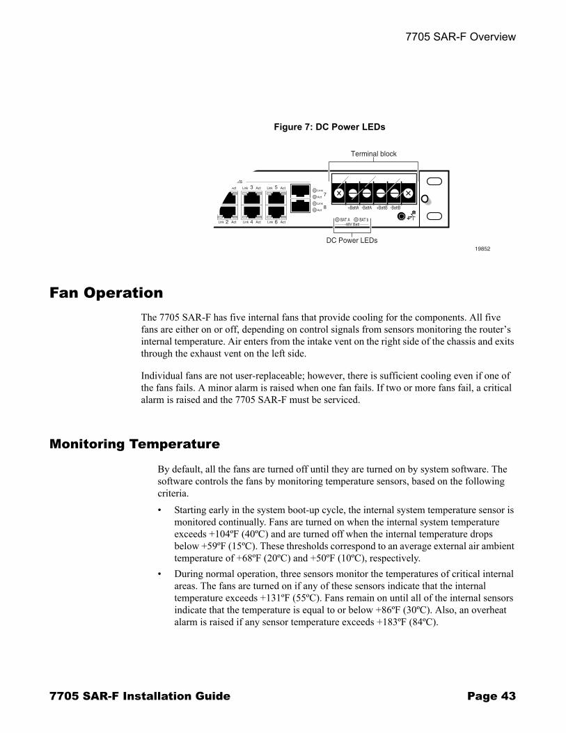
7705 SAR-F Overview . . . . . . . . . . . . . . . . . . . . . . . . . . . . . . . . . . . . . . . . . . . . . . . . . . . . . . . . . . . . . 39Figure 4: 7705 SAR-F Front View . . . . . . . . . . . . . . . . . . . . . . . . . . . . . . . . . . . . . . . . . . . . . . . . . . . . . . . . . . 40Figure 5: 7705 SAR-F Control and Switching Features . . . . . . . . . . . . . . . . . . . . . . . . . . . . . . . . . . . . . . . . . . 41Figure 6: T1/E1 and Ethernet Ports . . . . . . . . . . . . . . . . . . . . . . . . . . . . . . . . . . . . . . . . . . . . . . . . . . . . . . . . . 42Figure 7: DC Power LEDs . . . . . . . . . . . . . . . . . . . . . . . . . . . . . . . . . . . . . . . . . . . . . . . . . . . . . . . . . . . . . . . . 43
Site Preparation . . . . . . . . . . . . . . . . . . . . . . . . . . . . . . . . . . . . . . . . . . . . . . . . . . . . . . . . . . . . . . . . . . 47Figure 8: Chassis Clearance Requirements (View from Top) . . . . . . . . . . . . . . . . . . . . . . . . . . . . . . . . . . . . . 53
Installing the Chassis . . . . . . . . . . . . . . . . . . . . . . . . . . . . . . . . . . . . . . . . . . . . . . . . . . . . . . . . . . . . . 59Figure 9: Unpacking the 7705 SAR-F Chassis . . . . . . . . . . . . . . . . . . . . . . . . . . . . . . . . . . . . . . . . . . . . . . . . 61Figure 10: Installing the 7705 SAR-F Chassis in a Rack . . . . . . . . . . . . . . . . . . . . . . . . . . . . . . . . . . . . . . . . . . 63Figure 11: Preparing the Ground Wire . . . . . . . . . . . . . . . . . . . . . . . . . . . . . . . . . . . . . . . . . . . . . . . . . . . . . . . . 65Figure 12: Attaching the Chassis Ground Connector . . . . . . . . . . . . . . . . . . . . . . . . . . . . . . . . . . . . . . . . . . . . 66
DC Power Connections . . . . . . . . . . . . . . . . . . . . . . . . . . . . . . . . . . . . . . . . . . . . . . . . . . . . . . . . . . . . 69Figure 13: Attaching a Ring Lug to a Power Cable . . . . . . . . . . . . . . . . . . . . . . . . . . . . . . . . . . . . . . . . . . . . . . 71Figure 14: Wiring the -48 VDC Power Supplies . . . . . . . . . . . . . . . . . . . . . . . . . . . . . . . . . . . . . . . . . . . . . . . . . 72Figure 15: Wiring the +24 VDC Power Supplies . . . . . . . . . . . . . . . . . . . . . . . . . . . . . . . . . . . . . . . . . . . . . . . . 72
SFPs . . . . . . . . . . . . . . . . . . . . . . . . . . . . . . . . . . . . . . . . . . . . . . . . . . . . . . . . . . . . . . . . . . . . . . . . . . . 75Figure 16: Installing an SFP . . . . . . . . . . . . . . . . . . . . . . . . . . . . . . . . . . . . . . . . . . . . . . . . . . . . . . . . . . . . . . . 77
Connecting Cables . . . . . . . . . . . . . . . . . . . . . . . . . . . . . . . . . . . . . . . . . . . . . . . . . . . . . . . . . . . . . . . 81Figure 17: Managing Cable Connections . . . . . . . . . . . . . . . . . . . . . . . . . . . . . . . . . . . . . . . . . . . . . . . . . . . . . 84Figure 18: External Synchronization Input and Output Connectors . . . . . . . . . . . . . . . . . . . . . . . . . . . . . . . . . . 87Figure 19: External Alarms Connector . . . . . . . . . . . . . . . . . . . . . . . . . . . . . . . . . . . . . . . . . . . . . . . . . . . . . . . . 88Figure 20: External Alarms Connector Pin Numbers . . . . . . . . . . . . . . . . . . . . . . . . . . . . . . . . . . . . . . . . . . . . . 88
Initializing and Provisioning . . . . . . . . . . . . . . . . . . . . . . . . . . . . . . . . . . . . . . . . . . . . . . . . . . . . . . . . 91Figure 21: Files on the Compact Flash . . . . . . . . . . . . . . . . . . . . . . . . . . . . . . . . . . . . . . . . . . . . . . . . . . . . . . . 94Figure 22: Console Port Connection . . . . . . . . . . . . . . . . . . . . . . . . . . . . . . . . . . . . . . . . . . . . . . . . . . . . . . . . . 95Figure 23: Management Port Connection . . . . . . . . . . . . . . . . . . . . . . . . . . . . . . . . . . . . . . . . . . . . . . . . . . . . . 96
List of Figures
Page 10 7705 SAR-F Installation Guide
Appendix A: 7705 SAR-F Connectors and LEDs . . . . . . . . . . . . . . . . . . . . . . . . . . . . . . . . . . . . . . 101Figure 24: 7705 SAR-F Connectors and LEDs . . . . . . . . . . . . . . . . . . . . . . . . . . . . . . . . . . . . . . . . . . . . . . . . 102
Appendix B: Pinout Assignments . . . . . . . . . . . . . . . . . . . . . . . . . . . . . . . . . . . . . . . . . . . . . . . . . . 107Figure 25: 7705 SAR-F Port Connectors . . . . . . . . . . . . . . . . . . . . . . . . . . . . . . . . . . . . . . . . . . . . . . . . . . . . . 108Figure 26: Management Port Pin Numbers . . . . . . . . . . . . . . . . . . . . . . . . . . . . . . . . . . . . . . . . . . . . . . . . . . . 108Figure 27: Console Port Pin Numbers . . . . . . . . . . . . . . . . . . . . . . . . . . . . . . . . . . . . . . . . . . . . . . . . . . . . . . . 109Figure 28: External Alarms Port Pin Numbers . . . . . . . . . . . . . . . . . . . . . . . . . . . . . . . . . . . . . . . . . . . . . . . . . .111Figure 29: Ethernet Port RJ-45 Connector Pin Numbers . . . . . . . . . . . . . . . . . . . . . . . . . . . . . . . . . . . . . . . . 113Figure 30: T1/E1 Port RJ-45 Connector Pin Numbers . . . . . . . . . . . . . . . . . . . . . . . . . . . . . . . . . . . . . . . . . . 114

7705 SAR-F Installation Guide Page 11
List of Acronyms
Acronym Expansion
2G second generation wireless telephone technology
3G third generation mobile telephone technology
5620 SAM 5620 Service Aware Manager
7705 SAR 7705 Service Aggregation Router
ABR available bit rate
AC alternating currentattachment circuit
ACL access control list
ACR adaptive clock recovery
AIS alarm indication signal
ANSI American National Standards Institute
Apipe ATM VLL
ARP address resolution protocol
AS autonomous system
ASAP any service, any port
ATM asynchronous transfer mode
ATM PVC ATM permanent virtual circuit
B-bit beginning bit (first packet of a fragment)
Batt A battery A
Bellcore Bell Communications Research
BFD bidirectional forwarding detection
BITS building integrated timing supply
BOF boot options file

List of Acronyms
Page 12 7705 SAR-F Installation Guide
BRAS Broadband Remote Access Server
BSC Base Station Controller
BSTA Broadband Service Termination Architecture
BTS base transceiver station
CAS channel associated signaling
CBN common bonding networks
CBS committed buffer space
CC control channel
CE customer edgecircuit emulation
CEM circuit emulation
CES circuit emulation services
CESoPSN circuit emulation services over packet switched network
CIDR classless inter-domain routing
CIR committed information rate
CLI command line interface
CLP cell loss priority
CoS class of service
CPE customer premises equipment
Cpipe circuit emulation (or TDM) VLL
CPU central processing unit
CRC cyclic redundancy check
CRON a time-based scheduling service (from chronos = time)
CSM Control and Switching Module
CSPF constrained shortest path first
Acronym Expansion

List of Acronyms
7705 SAR-F Installation Guide Page 13
CV connection verificationcustomer VLAN (tag)
CW control word
DC direct current
DC-C DC return - common
DC-I DC return - isolated
DCO digitally controlled oscillator
DDoS distributed DoS
DHCP dynamic host configuration protocol
DNS domain name server
DoS denial of service
dot1q IEEE 802.1q encapsulation for Ethernet interfaces
DPLL digital phase locked loop
DSCP differentiated services code point
DSL digital subscriber line
DSLAM digital subscriber line access multiplexer
DTE data termination equipment
DU downstream unsolicited
e911 enhanced 911 service
E-bit ending bit (last packet of a fragment)
ECMP equal cost multi-path
EFM Ethernet in the first mile
ELER egress label edge router
Epipe Ethernet VLL
ESD electrostatic discharge
ETE end-to-end
Acronym Expansion

List of Acronyms
Page 14 7705 SAR-F Installation Guide
EVDO evolution - data optimized
EXP bits experimental bits
FC forwarding class
FCS frame check sequence
FDB forwarding database
FDL facilities data link
FEC forwarding equivalence class
FIB forwarding information base
FTN FEC-to-NHLFE
FTP file transfer protocol
GigE Gigabit Ethernet
GRE generic routing encapsulation
GSM Global System for Mobile Communications (2G)
HEC header error control
HSDPA high-speed downlink packet access
HSPA high-speed packet access
IBN isolated bonding networks
ICMP Internet control message protocol
ICP IMA control protocol cells
IEEE Institute of Electrical and Electronics Engineers
IES Internet Enhanced Service
IETF Internet Engineering Task Force
ILER ingress label edge router
ILM incoming label map
IMA inverse multiplexing over ATM
IOM input/output module
Acronym Expansion
List of Acronyms
7705 SAR-F Installation Guide Page 15
IP Internet Protocol
LCP link control protocol
LDP label distribution protocol
LER label edge router
LLID loopback location ID
LSP label switched path
LSR label switch router
LTN LSP ID to NHLFE
MAC media access control
MBB make-before-break
MBS maximum buffer spacemaximum burst sizemedia buffer space
MD5 message digest version 5 algorithm
MDA media dependent adapter
MEF Metro Ethernet Forum
MFC multi-field classification
MIB management information base
MIR minimum information rate
MLPPP multilink point-to-point protocol
MP multilink protocol
MPLS multiprotocol label switching
MRRU maximum received reconstructed unit
MRU maximum receive unit
MTSO mobile trunk switching office
MTU maximum transmission unitmulti-tenant unit
Acronym Expansion
List of Acronyms
Page 16 7705 SAR-F Installation Guide
NHLFE next hop label forwarding entry
NNI network-to-network interface
Node B similar to BTS but used in 3G networks � term is used in UMTS (3G systems) while BTS is used in GSM (2G systems)
OAM operations, administration, and maintenance
OAMPDU OAM protocol data units
OS operating system
OSS operations support system
PDU protocol data units
PDV packet delay variation
PDVT packet delay variation tolerance
PE provider edge router
PHB per-hop behavior
PHY physical layer
PID protocol ID
PIR peak information rate
POP point of presence
PPP point-to-point protocol
PSN packet switched network
PVC permanent virtual circuit
PVCC permanent virtual channel connection
PW pseudowire
PWE3 pseudowire emulation edge-to-edge
QoS quality of service
RAN Radio Access Network
RDI remote defect indication
Acronym Expansion

List of Acronyms
7705 SAR-F Installation Guide Page 17
RED random early discard
RNC Radio Network Controller
RSVP-TE resource reservation protocol - traffic engineering
R&TTE Radio and Telecommunications Terminal Equipment
RT receive/transmit
RTM route table manager
RTN battery return
RTP real-time protocol
SAA service assurance agent
SAP service access point
SAR-8 7705 Service Aggregation Router - 8-slot chassis
SAR-F 7705 Service Aggregation Router - fixed form-factor chassis
SAToP structure-agnostic TDM over packet
SDP service destination point
SIR sustained information rate
SLA Service Level Agreement
SNMP Simple Network Management Protocol
SNTP simple network time protocol
SPE source provider edge router
SPF shortest path first
SR service router (includes 7710 SR, 7750 SR)
SSH secure shell
SSU system synchronization unit
SVC switched virtual circuit
TCP transmission control protocol
TDM time division multiplexing
Acronym Expansion

List of Acronyms
Page 18 7705 SAR-F Installation Guide
TLDP targeted LDP
TLV type length value
ToS type of service
TPE target provider edge router
TPID tag protocol identifier
TTL time to live
TTM tunnel table manager
UBR unspecified bit rate
UDP user datagram protocol
UMTS Universal Mobile Telecommunications System (3G)
UNI user-to-network interface
VC virtual circuit
VCC virtual channel connection
VCCV virtual circuit connectivity verification
VCI virtual circuit identifier
VLAN virtual LAN
VLL virtual leased line
VoIP voice over IP
VP virtual path
VPC virtual path connection
VPI virtual path identifier
VPN virtual private network
VPRN virtual private routed network
WCDMA wideband code division multiple access (transmission protocol used in UMTS networks)
WRED weighted random early discard
Acronym Expansion

7705 SAR-F Installation Guide Page 19
Preface
About This GuideThis guide provides an overview of the Alcatel-Lucent 7705 Service Aggregation Router (SAR-F chassis), recommendations for preparing the site, procedures for installing and grounding the router in a standard 19-inch utility rack, and instructions for connecting and provisioning the router.
After the hardware installation process is completed, refer to the 7705 SAR OS documentation set (listed below) for details on the boot process, software configuration, and Command Line Interface (CLI) information to configure system and network parameters.
List of Technical PublicationsThe 7705 SAR-series OS documentation set is composed of the following guides:
� 7705 SAR OS Basic System Configuration GuideThis guide describes basic system configurations and operations.
� 7705 SAR OS System Management GuideThis guide describes system security and access configurations as well as event logging and accounting logs.
� 7705 SAR OS Interface Configuration GuideThis guide describes card and port provisioning.
� 7705 SAR OS Router Configuration GuideThis guide describes logical IP routing interfaces, IP-based filtering, and routing policies.
� 7705 SAR OS MPLS GuideThis guide describes how to configure Multiprotocol Label Switching (MPLS) and Label Distribution Protocol (LDP).
� 7705 SAR OS Services GuideThis guide describes how to configure service parameters such as service access points (SAPs), service destination points (SDPs), customer information, user services, and Operations, Administration and Management (OAM) tools.

Preface
Page 20 7705 SAR-F Installation Guide
� 7705 SAR OS Quality of Service GuideThis guide describes how to configure Quality of Service (QoS) policy management.
Warnings and NotesObserve the warnings and notes in this guide to avoid injury or router damage during installation and maintenance. Follow the safety procedures and guidelines when working with and near electrical equipment. Warning statements and notes are provided in each chapter.
AudienceThis guide is intended for network installers and system administrators who are responsible for installing, configuring, or maintaining networks. This guide assumes you are familiar with electronic and networking technologies.
Information SymbolsTable 1 describes symbols contained in this guide.
Table 1: Information Symbols
Symbol Meaning Description
Danger This symbol warns that improper handling and installation could result in bodily injury. An electric shock hazard could exist. Before you begin work on this equipment, be aware of hazards involving electrical circuitry, be familiar with networking environments, and instigate accident prevention procedures.
Warning This symbol warns that improper handling and installation could result in equipment damage or loss of data.
Caution This symbol warns that improper handling may reduce your component or system performance.
Preface
7705 SAR-F Installation Guide Page 21
Technical SupportIf you purchased a service agreement for your 7705 SAR-F and related products from a distributor or authorized reseller, contact the technical support staff for that distributor or reseller for assistance. If you purchased an Alcatel-Lucent service agreement, contact technical assistance at:
Web: http://www1.alcatel-lucent.com/comps/pages/carrier_support.jhtml
Note This symbol provides additional operational information.
Class 1 laser products are identified in the adapter card installation guides. Only approved Class 1 replaceable laser transceivers should be used with this product.
Table 1: Information Symbols (Continued)
Symbol Meaning Description
Class 1 Laser Product

Preface
Page 22 7705 SAR-F Installation Guide
7705 SAR-F Installation Guide Page 23
Mandatory Regulations
In This ChapterThe following sections describe the mandatory regulations that govern the installation and operation of the 7705 SAR-F:
� List of Terms on page 24� General Requirements on page 25� Canada Regulations on page 28� United States Regulations on page 29� European Union Regulations on page 31� Australia/New Zealand Regulations on page 35� China Regulations on page 36
Mandatory Regulations
Page 24 7705 SAR-F Installation Guide
List of TermsTable 2 lists the terms used in this chapter.
Table 2: List of Terms
Term Expansion
ACMA Australian Communications and Media Authority
ACTA Administrative Council for Terminal Attachments
ANSI American National Standards Institute
AS/NZ Australian/New Zealand standard
CE Conformité Européene
CFR Code of Federal Regulations
CSA International Canadian Standards Association International
EEC European Economic Community
EMC Electromagnetic Compatibility
EMI Electromagnetic Interference
EN European Standards
ETSI European Telecommunications Standards Institute
FCC Federal Communications Commission
ICES Interference Causing Equipment Standard
IEC International Electrotechnical Commission
IEE Institute of Electrical Engineers (UK)
LVD Low Voltage Directive
NRTL Nationally Recognized Testing Laboratory
OSHA (USA) Occupational Safety and Health Administration (USA)
RoHS Restriction of the use of certain Hazardous Substances
SELV Safety Extra Low Voltage
UL Underwriters Laboratories
WEEE Waste Electrical and Electronic Equipment
Mandatory Regulations
7705 SAR-F Installation Guide Page 25
General RequirementsThe sections that follow outline the mandatory regulations that govern the installation and operation of the 7705 SAR-F. You must adhere to these instructions so that your system meets regulatory requirements.
Equipment Interconnection PointsInterconnection points of the 7705 SAR-F are defined as the following SELV connectors:
� T1/E1� Ethernet (10/100/1000 Base-T)� alarms� management ports� external clock inputs and clock outputs (2 MHz, 5 MHz, 10 MHz)
SELVConnect SELV circuits on this equipment only to other circuits that comply with the requirements of SELV circuits as defined in CSA C22.2 No. 60950-1, UL 60950-1, EN 60950-1, AS/NZS 60950-1, and IEC60950-1.
Prevention of AccessThe 7705 SAR-F must be accessible only to authorized personnel. Install this apparatus in a restricted access location or similar environment to prevent unauthorized access.
Warning: There are no user-serviceable parts in this unit. Refer servicing to qualified personnel.
Warning: The unit should be connected to a DC branch circuit with a minimum 5 A and maximum 10 A circuit breaker or fuse that meets the requirements for branch circuit protection. A suitable disconnect device, such as a circuit breaker or switch, must be provided in the DC branch circuit and must be used to disconnect power to the system during servicing.

Mandatory Regulations
Page 26 7705 SAR-F Installation Guide
Laser Interface The 7705 SAR-F uses a fiber-optic communications method and is an FDA and IEC Class 1 Laser product. Only trained service personnel thoroughly familiar with laser radiation hazards should install or remove the fiber-optic cables and cards in this system.
Protective Safety Ground (Earth)The cable used for safety ground should be at least the same gauge as the supply conductors, green and yellow in color, and of sufficient length to connect the building earth point to the chassis ground connection (refer to Chassis Ground Wiring on page 65 for specific instructions on connecting the chassis ground).
EMC ComplianceEMC compliance may require the use of shielded cables or other special accessories. Where required, these special accessories must be installed as per the instructions.
To maintain EMC compliance, cables that are shielded and grounded at both ends must be used on the following interfaces and ports:
� Management (Ethernet) and DB9 console ports� DB15 Alarm port� Synchronization interfaces� Ethernet interfaces
→ Fast Ethernet (CAT5 shielded cable)→ Gigabit Ethernet (CAT5E shielded cable)
� T1 and E1 interfaces
Mandatory Regulations
7705 SAR-F Installation Guide Page 27
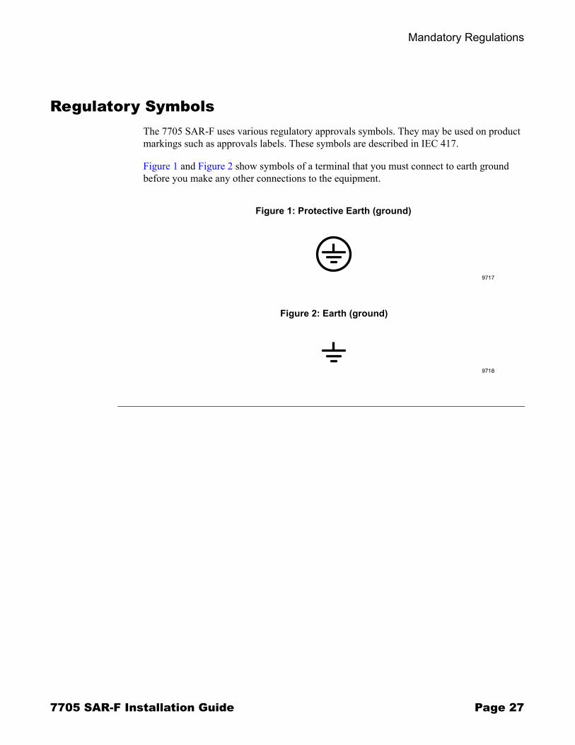
Regulatory SymbolsThe 7705 SAR-F uses various regulatory approvals symbols. They may be used on product markings such as approvals labels. These symbols are described in IEC 417.
Figure 1 and Figure 2 show symbols of a terminal that you must connect to earth ground before you make any other connections to the equipment.
Figure 1: Protective Earth (ground)
Figure 2: Earth (ground)
9717
9718

Mandatory Regulations
Page 28 7705 SAR-F Installation Guide
Canada RegulationsThis section describes the mandatory regulations that govern the installation and operation of the 7705 SAR-F in Canada.
Industry Canada Regulations
ICES-003: Interference-Causing Equipment Standard Digital Apparatus
This Class A digital apparatus complies with Canadian ICES-003.
Cet appareil numérique de la classe A est conforme à la norme NMB-003 du Canada.
IC CS-03: Specification for Terminal Equipment, Terminal Systems, Network Protection Devices, Connection Arrangements and Hearing Aids Compatibility
This product meets the applicable Industry Canada technical specifications with respect to IC CS-03: Specification for Terminal Equipment, Terminal Systems, Network Protection Devices, Connection Arrangements and Hearing Aids Compatibility.
Registration number: IC: 1737F-0011
EMC ComplianceEMC compliance may require the use of shielded cables or other special accessories. Where required, these special accessories must be installed as per the instructions.
Safety Approval for DC SystemsThe DC source for the system must meet the requirements of a SELV source to comply with CSA standard C22.2 No. 60950-1. Use the system with a SELV secondary source that is electrically isolated from the AC source and that is grounded reliably.
The 7705 SAR-F is safety certified according to CSA standard C22.2 No. 60950-1 by CSA.
Mandatory Regulations
7705 SAR-F Installation Guide Page 29
United States RegulationsThis section describes the mandatory regulations that govern the installation and operation of the 7705 SAR-F in the United States.
Federal Communications Commission
FCC Part 15
Important! Changes or modifications not expressly approved by Alcatel-Lucent could void the user�s authority to operate the equipment.
This device complies with Part 15 of the FCC Rules. Operation is subject to the following two conditions: (1) This device may not cause harmful interference, and (2) this device must accept any interference received, including interference that may cause undesired operation.
FCC Part 68
The T1 network interface on this equipment meets the FCC specifications.
This equipment complies with Part 68 of the FCC rules and the requirements adopted by the ACTA. On the equipment is a label that contains, among other information, a product identifier in the format of AAAEQ##TXXXX.
Identification Number: GQ6DENAN7705SAR-F
In the event that repairs to this equipment are needed, contact:
Technical Support ServicesAlcatel-LucentWithin the United States: 1-866-582-3688, prompt 1
Note: This equipment has been tested and found to comply with the limits for a Class A digital device, pursuant to Part 15 of the FCC Rules. These limits are designed to provide reasonable protection against harmful interference when the equipment is operated in a commercial environment. This equipment generates, uses, and can radiate radio frequency energy and, if not installed and used in accordance with the instruction manual, may cause harmful interference to radio communications. Operation of this equipment in a residential area is likely to cause harmful interference, in which case the user will be required to correct the interference at the user�s expense.
Mandatory Regulations
Page 30 7705 SAR-F Installation Guide
NRTLThis equipment is certified by the NRTL as meeting the requirements of UL 60950-1, Safety of Information Technology Equipment.
NRTL Approval for External DC SuppliesWhen the system is equipped with an AC rectifier, the rectifier must have NRTL-accredited approval. In addition, the DC outputs must meet UL 60950-1 SELV requirements.
Safety Approval for DC SystemsThe DC source for the system must meet the requirements of a SELV source in accordance with UL 60950-1. You must use the system with a SELV secondary source that is electrically isolated from the AC source and that is grounded reliably.
Food and Drug AdministrationThis product complies with 21 CFR 1040.10 and 1040.11 regulations, which govern the safe use of lasers. Only qualified service personnel, thoroughly familiar with laser radiation hazards, should install or remove the fiber-optic cables used in this system. You can find information about the safe use of lasers in ANSI Z 136.1: Safe Use of Lasers and ANSI Z 136.2: Safe Use of Lasers in Optical Fiber Communications Systems. You can obtain these documents and other instructional material from:
Laser Institute of America12424 Research Parkway, Suite 125Orlando, FL 32826-3274

Mandatory Regulations
7705 SAR-F Installation Guide Page 31
European Union Regulations
Declaration of ConformityHereby, Alcatel-Lucent declares that the equipment documented in this publication is in compliance with the essential requirements and other relevant provisions of Directive 1999/5/EC and 2004/108/EC.
The technical documentation as required by the Conformity Assessment procedure is kept at the Alcatel-Lucent location that is responsible for this product. For more information please contact your local Alcatel-Lucent Customer Service Organization.
EU Compliance StatementThis product has been CE marked in accordance with the requirements of European Directive 99/05/EC, the Radio and Telecommunications Terminal Equipment Directive (R&TTE), and 2004/108/EC, the Electromagnetic Compatibility (EMC) Directive.
EMC/EMI ComplianceThe equipment complies with the following EMC and EMI specification: EN 300 386 Class A.
GeneralThis equipment must be permanently grounded.
Laser InterfaceThe system uses laser devices that are rated in accordance with IEC 60825-1 as Class 1 devices.

Mandatory Regulations
Page 32 7705 SAR-F Installation Guide
Safety Approval for DC SystemsThe DC source for the system must meet the requirements of a SELV source as defined in EN 60950-1. For 60V station battery systems, the source is considered TNV-2 as per IEC/EN 60950-1 and must have reinforced insulation from the AC mains.
The equipment complies with the following Product Safety specification: EN 60950-1.
Protective Earth Protective earth is referred to as chassis ground in this document. A green and yellow colored earth wire must be connected from the site equivalent of the AC earth to all shelves in accordance with IEE Wiring Regulations (16th edition). This connection is made via the chassis ground connection (refer to Chassis Ground Wiring on page 65 for specific instructions on connecting the protective earth). The protective earth is also carried by the mains plug and socket (for AC systems only).
Approval for External AC RectifiersWhen the system is equipped with an external AC rectifier, the rectifier must meet EN 60950-1 SELV DC output requirements. Make sure that the rectifier is rated and adjusted for the appropriate AC input voltage and frequency for the country where it is installed. Set the output of the rectifier according to the installation and operating instructions of the manufacturer, to provide output levels that coincide with the nominal DC input ratings of the system.
Eco-Environmental
Packaging Collection and Recovery Requirements
Countries, states, localities, or other jurisdictions may require that systems be established for the return and/or collection of packaging waste from the consumer, or other end user, or from the waste stream. Additionally, reuse, recovery, and/or recycling targets for the return and/or collection of the packaging waste may be established.
For more information regarding collection and recovery of packaging and packaging waste within specific jurisdictions, please contact the Environmental Health and Safety organization.
Mandatory Regulations
7705 SAR-F Installation Guide Page 33
For installations not performed by Alcatel-Lucent, please contact the Alcatel-Lucent Customer Support Center at:
Technical Support Services+1 630 224 4672, prompt 2
Recycling / Take-back / Disposal of Product
Electronic products bearing or referencing the symbol shown in Figure 3, when put on the market within the European Union, shall be collected and treated at the end of their useful life in compliance with applicable European Union and local legislation. They shall not be disposed of as part of unsorted municipal waste. Due to materials that may be contained in the product, such as heavy metals or batteries, the environment and human health may be negatively impacted as a result of inappropriate disposal.
Moreover, in compliance with legal requirements and contractual agreements, where applicable, Alcatel-Lucent will offer to provide for the collection and treatment of Alcatel-Lucent products bearing the logo at the end of their useful life, or products displaced by Alcatel-Lucent equipment offers. For information regarding take-back of equipment by Alcatel-Lucent, or for more information regarding the requirements for recycling/disposal of product, please contact your Alcatel-Lucent Account Manager or Alcatel-Lucent Takeback Support at [email protected].
Note: In the European Union, the WEEE symbol (a wheeled trash bin that has been crossed out and is positioned above a solid bar) indicates that the product was put on the market after 13 August 2005. This product is compliant with the WEEE marking requirements of DIRECTIVE 2002/96/EC Waste Electrical and Electronic Equipment (WEEE).
Figure 3: WEEE Symbol for post-August 13, 2005 Product

Mandatory Regulations
Page 34 7705 SAR-F Installation Guide
Material Content ComplianceEuropean Union (EU) Directive 2002/95/EC, �Restriction of the use of certain Hazardous Substances� (RoHS), restricts the use of lead, mercury, cadmium, hexavalent chromium, and certain flame retardants in electrical and electronic equipment. This Directive applies to electrical and electronic products placed on the EU market after 1 July 2006, with various exemptions, including an exemption for lead solder in network infrastructure equipment. Alcatel-Lucent products shipped to the EU after 1 July 2006 comply with the EU RoHS Directive.

Mandatory Regulations
7705 SAR-F Installation Guide Page 35
Australia/New Zealand RegulationsThis section describes the mandatory regulations that govern the installation and operation of the 7705 SAR-F in Australia and New Zealand.
ACMA RegulationsThe 7705 SAR-F complies with the ACMA requirements and the product is marked with the 'A Tick' under the Supplier Code N594.
EMC
This Class A digital apparatus complies with AS/NZS CISPR22.
Telecom
This product meets the applicable ACMA technical specifications: AS/ACIF S016.
Safety
All products supplied in Australia are to be safe and to comply with an applicable Australian Standard electrical safety standard.
The 7705 SAR-F complies with the AS/NZS 60950�Business Equipment, Computers, Telecommunications requirements.

Mandatory Regulations
Page 36 7705 SAR-F Installation Guide
China RegulationsThe statements that follow are the product conformance statements that apply to the 7705 SAR-F when deployed in China.
SafetyThe equipment complies with the Product Safety specification of IEC 60950-1.Eco-Environmental.
Packaging Collection and Recovery RequirementsCountries, states, localities, or other jurisdictions may require that systems be established for the return and/or collection of packaging waste from the consumer, or other end user, or from the waste stream. Additionally, reuse, recovery, and/or recycling targets for the return and/or collection of the packaging waste may be established.
For more information regarding collection and recovery of packaging and packaging waste within specific jurisdictions, please contact the Alcatel-Lucent Environmental Health and Safety organization. For installations not performed by Alcatel-Lucent, please contact the Alcatel-Lucent Customer Support Center at:
Technical Support Services+1 630 224 4672, prompt 2
Material Content ComplianceThe People�s Republic of China Ministry of Information Industry has published a regulation (Order #39) and associated standards regarding restrictions on hazardous substances (China RoHS). Currently, the legislation requires all Electronic and Information Products (EIP) to comply with certain labeling and documentation requirements. Alcatel-Lucent products manufactured on or after 1 March 2007, that are intended for sale to customers in the China market, comply with these requirements.

Mandatory Regulations
7705 SAR-F Installation Guide Page 37
In accordance with the People�s Republic of China Electronic Industry Standard �Marking for the Control of Pollution Caused by Electronic Information Product� (SJ/T11364-2006), customers may access Alcatel-Lucent�s Hazardous Substances Table information at either of the following two URLs:
� Access via the Alcatel-Lucent Corporate website at:http://www.alcatel-lucent.com/cn
� Access via the Alcatel Shanghai Bell website at: http://www.alcatel-sbell.com.cn/

Mandatory Regulations
Page 38 7705 SAR-F Installation Guide
7705 SAR-F Installation Guide Page 39
7705 SAR-F Overview
In This ChapterThis chapter provides an introduction to the Alcatel-Lucent 7705 SAR-F:
� 7705 SAR-F Components on page 40→ Control and Switching on page 41→ T1/E1 and Ethernet Ports on page 42→ Power Supply Inputs on page 42→ Fan Operation on page 43
� Notes on 7705 SAR-F and 7705 SAR-8 on page 44� SAR System Installation Process on page 46
7705 SAR-F Overview
Page 40 7705 SAR-F Installation Guide
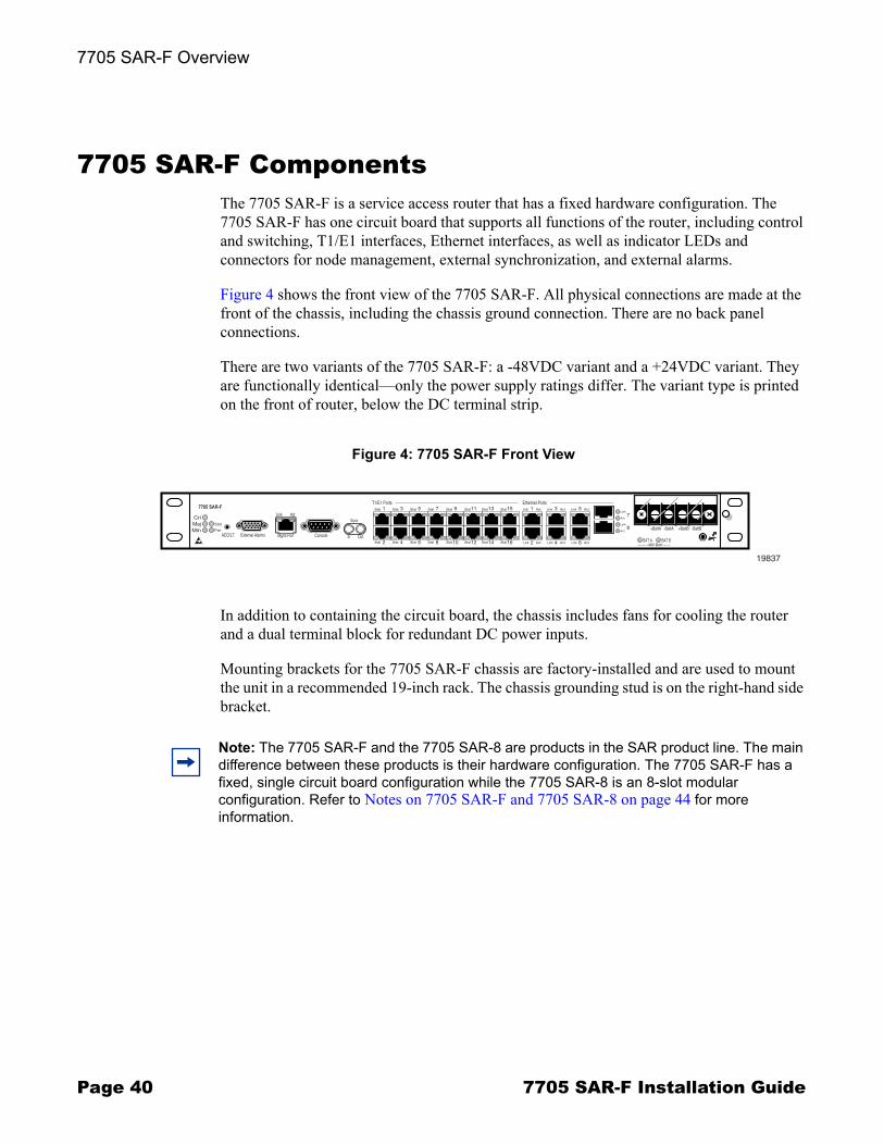
7705 SAR-F ComponentsThe 7705 SAR-F is a service access router that has a fixed hardware configuration. The 7705 SAR-F has one circuit board that supports all functions of the router, including control and switching, T1/E1 interfaces, Ethernet interfaces, as well as indicator LEDs and connectors for node management, external synchronization, and external alarms.
Figure 4 shows the front view of the 7705 SAR-F. All physical connections are made at the front of the chassis, including the chassis ground connection. There are no back panel connections.
There are two variants of the 7705 SAR-F: a -48VDC variant and a +24VDC variant. They are functionally identical�only the power supply ratings differ. The variant type is printed on the front of router, below the DC terminal strip.
In addition to containing the circuit board, the chassis includes fans for cooling the router and a dual terminal block for redundant DC power inputs.
Mounting brackets for the 7705 SAR-F chassis are factory-installed and are used to mount the unit in a recommended 19-inch rack. The chassis grounding stud is on the right-hand side bracket.
Figure 4: 7705 SAR-F Front View
Cri
7705 SAR-F
MajMin
Stat
Pwr
ACO/LT External Alarms Mgmt Port Console
Link Act
In Out
1T1/E1 Ports
Stat 3Stat 5Stat 7Stat 9Stat 11Stat 13Stat 15Stat 1Link Act
2Link Act
3Link Act
4Link Act
57
8
Link Act
6Link Act2Stat 4Stat 6Stat 8Stat 10Stat 12Stat 14Stat 16Stat
Sync
Ethernet Ports
Link
Act
Link
Act
BAT A BAT B
+BattA -BattA +BattB -BattB
19837
-48V Batt
Note: The 7705 SAR-F and the 7705 SAR-8 are products in the SAR product line. The main difference between these products is their hardware configuration. The 7705 SAR-F has a fixed, single circuit board configuration while the 7705 SAR-8 is an 8-slot modular configuration. Refer to Notes on 7705 SAR-F and 7705 SAR-8 on page 44 for more information.

7705 SAR-F Overview
7705 SAR-F Installation Guide Page 41
Control and SwitchingControl and switching on the 7705 SAR-F provide the following main functions:
� node management interfaces to the 7705 SAR-F (Management (Ethernet) and Console; see Figure 5)
� system synchronization and alarm interfaces for external inputs and outputs (see Figure 5)
� routing, switching, and services functions for the entire system
The 7705 SAR-F has a compact flash memory device that stores system boot software, OS software, and configuration files and logs. The compact flash device cannot be accessed or removed by an operator or installer.
The switching fabric receives and directs traffic to the appropriate interface ports according to the routing information.
Figure 5 identifies the connectors and LEDs that are part of the control and switching function. Refer to 7705 SAR-F Connectors and LEDs on page 102 for a description of these parts.
Figure 5: 7705 SAR-F Control and Switching Features
19837
StatusLED
ManagementPort
SynchronizationIn/Out
ACO/LT
ExternalAlarms port
Consoleport
Cri
7705 SAR-F
MajMin
Stat
Pwr
ACO/LT External Alarms Mgmt Port
Link Act
In Out
1T1/E1 Ports
Stat 3St-t
2Stat 4Stat
Sync
PowerLED
Console
7705 SAR-F Overview
Page 42 7705 SAR-F Installation Guide
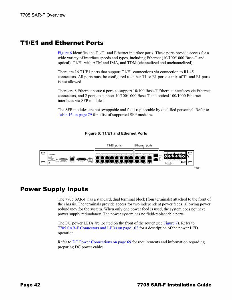
T1/E1 and Ethernet PortsFigure 6 identifies the T1/E1 and Ethernet interface ports. These ports provide access for a wide variety of interface speeds and types, including Ethernet (10/100/1000 Base-T and optical), T1/E1 with ATM and IMA, and TDM (channelized and unchannelized).
There are 16 T1/E1 ports that support T1/E1 connections via connection to RJ-45 connectors. All ports must be configured as either T1 or E1 ports; a mix of T1 and E1 ports is not allowed.
There are 8 Ethernet ports: 6 ports to support 10/100 Base-T Ethernet interfaces via Ethernet connectors, and 2 ports to support 10/100/1000 Base-T and optical 100/1000 Ethernet interfaces via SFP modules.
The SFP modules are hot-swappable and field-replaceable by qualified personnel. Refer to Table 16 on page 79 for a list of supported SFP modules.
Power Supply InputsThe 7705 SAR-F has a standard, dual terminal block (four terminals) attached to the front of the chassis. The terminals provide access for two independent power feeds, allowing power redundancy for the system. When only one power feed is used, the system does not have power supply redundancy. The power system has no field-replaceable parts.
The DC power LEDs are located on the front of the router (see Figure 7). Refer to 7705 SAR-F Connectors and LEDs on page 102 for a description of the power LED operation.
Refer to DC Power Connections on page 69 for requirements and information regarding preparing DC power cables.
Figure 6: T1/E1 and Ethernet Ports
Cri
7705 SAR-F
MajMin
Stat
Pwr
ACO/LT External Alarms Mgmt Port Console
Link Act
In Out
1T1/E1 Ports
Stat 3Stat 5Stat 7Stat 9Stat 11Stat 13Stat 15Stat 1Link Act
2Link Act
3Link Act
4Link Act
57
8
Link Act
6Link Act2Stat 4Stat 6Stat 8Stat 10Stat 12Stat 14Stat 16Stat
Sync
Ethernet Ports
Link
Act
Link
Act
BAT A BAT B
+BattA -BattA +BattB -BattB
-48V Batt
19851
T1/E1 ports Ethernet ports
7705 SAR-F Overview
7705 SAR-F Installation Guide Page 43
Fan OperationThe 7705 SAR-F has five internal fans that provide cooling for the components. All five fans are either on or off, depending on control signals from sensors monitoring the router�s internal temperature. Air enters from the intake vent on the right side of the chassis and exits through the exhaust vent on the left side.
Individual fans are not user-replaceable; however, there is sufficient cooling even if one of the fans fails. A minor alarm is raised when one fan fails. If two or more fans fail, a critical alarm is raised and the 7705 SAR-F must be serviced.
Monitoring Temperature
By default, all the fans are turned off until they are turned on by system software. The software controls the fans by monitoring temperature sensors, based on the following criteria.� Starting early in the system boot-up cycle, the internal system temperature sensor is
monitored continually. Fans are turned on when the internal system temperature exceeds +104ºF (40ºC) and are turned off when the internal temperature drops below +59ºF (15ºC). These thresholds correspond to an average external air ambient temperature of +68ºF (20ºC) and +50ºF (10ºC), respectively.
� During normal operation, three sensors monitor the temperatures of critical internal areas. The fans are turned on if any of these sensors indicate that the internal temperature exceeds +131ºF (55ºC). Fans remain on until all of the internal sensors indicate that the temperature is equal to or below +86ºF (30ºC). Also, an overheat alarm is raised if any sensor temperature exceeds +183ºF (84ºC).
Figure 7: DC Power LEDs
1Link Act
2Link Act
3Link Act
4Link Act
5
8
Link Act
6Link Act
Ethernet Ports
Link
Act
Link
Act
BAT A BAT b
19852
Terminal block
DC Power LEDs
7
+BattA -BattA +BattB -BattB
-48V Batt

7705 SAR-F Overview
Page 44 7705 SAR-F Installation Guide
The show chassis CLI command displays the fan status as one of the following:
� up � all fans are operating� minor failure � one fan has failed � critical failure � two or more fans have failed
The fan speed can be one of the following:
� full speed � all fans are on� off � all fans are off
An example of the Fan Information portion of the show chassis display is shown below:
Fan Information # of on-board fans : 5 Status : up Speed : full speed
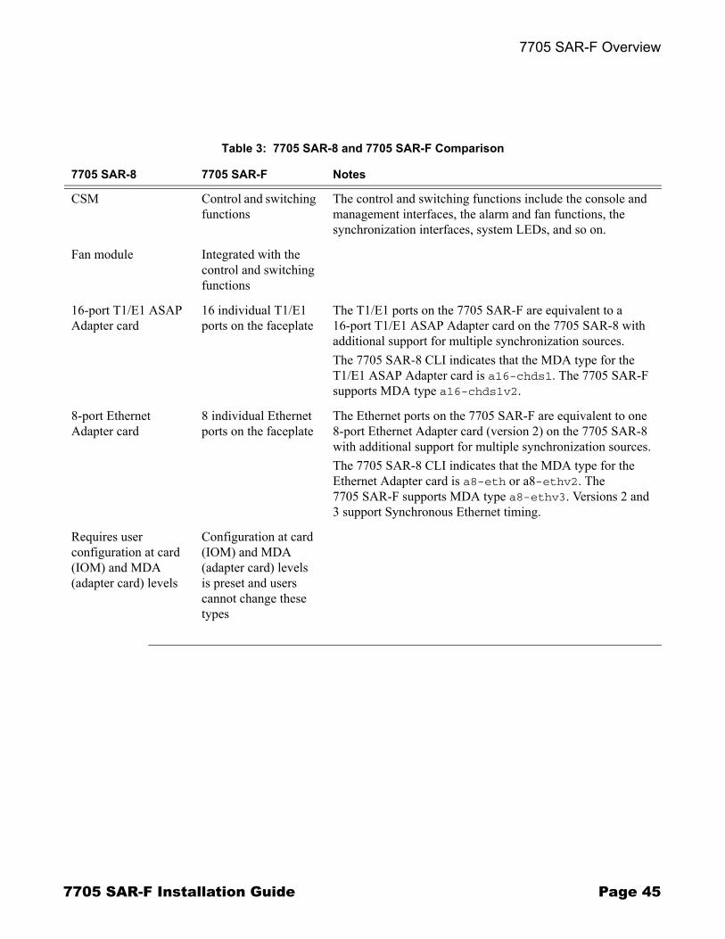
Notes on 7705 SAR-F and 7705 SAR-8The 7705 SAR-F and the 7705 SAR-8 run the same operating system software. The main difference between the products is their hardware configuration. The 7705 SAR-8 has an 8-slot chassis that supports two CSMs, six adapter cards, and a Fan module. The 7705 SAR-F chassis has a fixed hardware configuration, replacing the 7705 SAR-8 physical components (the CSM, Fan module, and adapter cards) with an all-in-one unit that provides comparable functional blocks, as detailed in Table 3.
The fixed configuration of the 7705 SAR-F means that provisioning the router at the �card slot� and �type� levels is preset and is not user-configurable. Operators begin configurations at the port level.
Note: Unless stated otherwise, references to the terms "Adapter card" and "CSM" throughout the 7705 SAR OS documentation set include the equivalent functional blocks on the 7705 SAR-F.
7705 SAR-F Overview
7705 SAR-F Installation Guide Page 45
Table 3: 7705 SAR-8 and 7705 SAR-F Comparison
7705 SAR-8 7705 SAR-F Notes
CSM Control and switching functions
The control and switching functions include the console and management interfaces, the alarm and fan functions, the synchronization interfaces, system LEDs, and so on.
Fan module Integrated with the control and switching functions
16-port T1/E1 ASAP Adapter card
16 individual T1/E1 ports on the faceplate
The T1/E1 ports on the 7705 SAR-F are equivalent to a 16-port T1/E1 ASAP Adapter card on the 7705 SAR-8 with additional support for multiple synchronization sources.The 7705 SAR-8 CLI indicates that the MDA type for the T1/E1 ASAP Adapter card is a16-chds1. The 7705 SAR-F supports MDA type a16-chds1v2.
8-port Ethernet Adapter card
8 individual Ethernet ports on the faceplate
The Ethernet ports on the 7705 SAR-F are equivalent to one 8-port Ethernet Adapter card (version 2) on the 7705 SAR-8 with additional support for multiple synchronization sources.The 7705 SAR-8 CLI indicates that the MDA type for the Ethernet Adapter card is a8-eth or a8-ethv2. The 7705 SAR-F supports MDA type a8-ethv3. Versions 2 and 3 support Synchronous Ethernet timing.
Requires user configuration at card (IOM) and MDA (adapter card) levels
Configuration at card (IOM) and MDA (adapter card) levels is preset and users cannot change these types
7705 SAR-F Overview
Page 46 7705 SAR-F Installation Guide
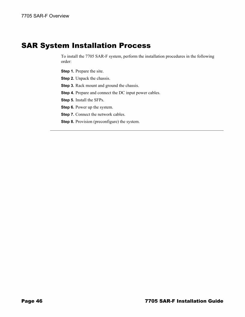
SAR System Installation ProcessTo install the 7705 SAR-F system, perform the installation procedures in the following order:
Step 1. Prepare the site.Step 2. Unpack the chassis.Step 3. Rack mount and ground the chassis.Step 4. Prepare and connect the DC input power cables.Step 5. Install the SFPs.Step 6. Power up the system.Step 7. Connect the network cables.Step 8. Provision (preconfigure) the system.

7705 SAR-F Installation Guide Page 47
Site Preparation
In This ChapterThis chapter provides information about preparing your site to install a 7705 SAR-F:
� Warnings and Notes on page 48� System Specifications on page 50
→ Chassis Specifications on page 50→ Environmental Specifications on page 50→ 7705 SAR-F Power Consumption on page 51
� Installation Locations on page 52→ Chassis Location Requirements on page 52
� Safety Considerations on page 54→ Placement on page 54→ Grounding on page 54→ Cabling on page 56→ Power on page 56→ Fans on page 57→ Storage on page 57→ Compliance on page 57
Site Preparation
Page 48 7705 SAR-F Installation Guide
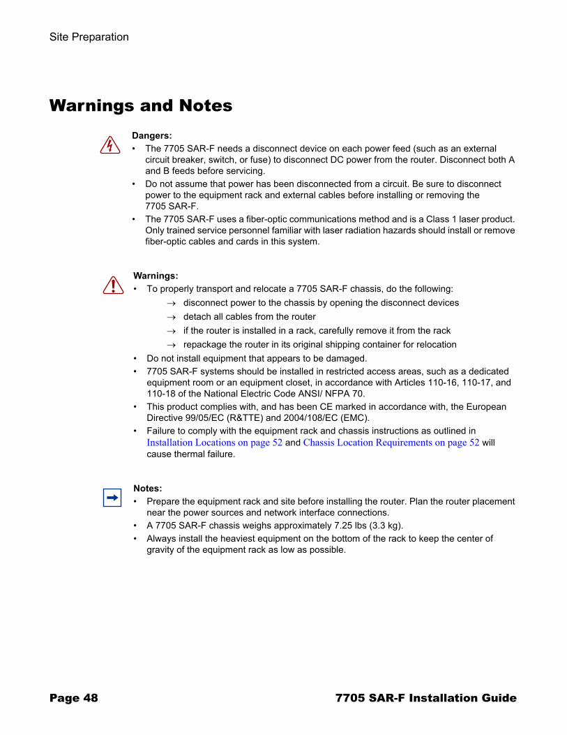
Warnings and Notes
Dangers: � The 7705 SAR-F needs a disconnect device on each power feed (such as an external
circuit breaker, switch, or fuse) to disconnect DC power from the router. Disconnect both A and B feeds before servicing.
� Do not assume that power has been disconnected from a circuit. Be sure to disconnect power to the equipment rack and external cables before installing or removing the 7705 SAR-F.
� The 7705 SAR-F uses a fiber-optic communications method and is a Class 1 laser product. Only trained service personnel familiar with laser radiation hazards should install or remove fiber-optic cables and cards in this system.
Warnings: � To properly transport and relocate a 7705 SAR-F chassis, do the following:
→ disconnect power to the chassis by opening the disconnect devices→ detach all cables from the router→ if the router is installed in a rack, carefully remove it from the rack→ repackage the router in its original shipping container for relocation
� Do not install equipment that appears to be damaged.� 7705 SAR-F systems should be installed in restricted access areas, such as a dedicated
equipment room or an equipment closet, in accordance with Articles 110-16, 110-17, and 110-18 of the National Electric Code ANSI/ NFPA 70.
� This product complies with, and has been CE marked in accordance with, the European Directive 99/05/EC (R&TTE) and 2004/108/EC (EMC).
� Failure to comply with the equipment rack and chassis instructions as outlined in Installation Locations on page 52 and Chassis Location Requirements on page 52 will cause thermal failure.
Notes: � Prepare the equipment rack and site before installing the router. Plan the router placement
near the power sources and network interface connections.� A 7705 SAR-F chassis weighs approximately 7.25 lbs (3.3 kg).� Always install the heaviest equipment on the bottom of the rack to keep the center of
gravity of the equipment rack as low as possible.
Site Preparation
7705 SAR-F Installation Guide Page 49
Notes: (continued)� To provide necessary stability, ensure that the equipment rack is bolted to the floor. Ceiling
brackets are useful to provide additional stability.� The equipment rack must be properly grounded.� Install the chassis in the equipment rack before installing SFPs.� Maintain a clearance of at least 2.5 in. (6.4 cm) at the front of the router for cable
management.� Maintain a clearance of at least 3 in. (7.6 cm) on each side of the router to ensure adequate
air intake and exhaust. When mounting the router in a rack, ensure that the rack complies with all requirements outlined in Chassis Location Requirements on page 52.
� The 7705 SAR-F includes factory-installed, rack-mounting brackets to mount the router in a 19-inch equipment rack.

Site Preparation
Page 50 7705 SAR-F Installation Guide
System Specifications
Chassis Specifications
Environmental Specifications
Table 4: 7705 SAR-F Chassis Specifications
Parameter Description
Dimensions (without mounting brackets)
(1.75 x 17.5 x 9.5 in.) (H x W x D)(4.45 x 44.4 x 25.0 cm)
Chassis weight 7.25 lbs (3.3 kg)
Mounting Mount in a recommended 19-inch equipment rackRack-mount brackets are factory-installed for 19-inch NEBS mounting
Table 5: Environmental Specifications
Parameter Description
Normal operating temperature -40 to 149ºF (-40 to +65ºC)
Cold start temperature -40ºF (-40ºC)
Relative humidity 5 to 85% (non-condensing)
Normal relative humidity Not to exceed 29 g of water per cubic meter of air
Altitude range Between 197 ft (60 m) below sea level and 5906 ft (1800 m) above sea level (70kPa to 106kPa)
Shock and vibration Very low levels for continuous duration (similar to modern office building, for example)
Earthquake Suitable for high risk areas (Zone 4/California, for short duration)
Pollution degree (1) 2
Site Preparation
7705 SAR-F Installation Guide Page 51
Note:1. Pollution degree is as defined in IEC 60950.
7705 SAR-F Power Consumption
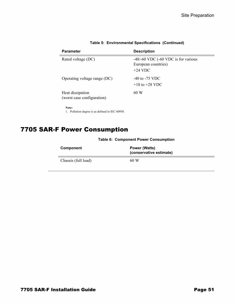
Rated voltage (DC) -48/-60 VDC (-60 VDC is for various European countries)+24 VDC
Operating voltage range (DC) -40 to -75 VDC+18 to +28 VDC
Heat dissipation (worst case configuration)
60 W
Table 5: Environmental Specifications (Continued)
Parameter Description
Table 6: Component Power Consumption
Component Power (Watts)(conservative estimate)
Chassis (full load) 60 W
Site Preparation
Page 52 7705 SAR-F Installation Guide
Installation LocationsThe 7705 SAR-F is intended to be installed in cell site or other facilities that provide weather protection and an extended temperature-controlled environment. The facilities provide protection from mold growth, pest incursion, and precipitation. The 7705 SAR-F is not intended for installation in outdoor facilities.
Airflow on the 7705 SAR-F is defined as EC Class (S) SR-SL per GR3028. For proper thermal performance, the following conditions must be met.
� The rack must be constructed using channel or angle rack uprights that are at least 1.25 in. (3.2 cm) deep, 5 in. (12.7 cm) wide (maximum) (see Figure 8).
� For seismic applications, the rack must be an approved Seismic Frame.� 7705 SAR-F deployments in closed cabinets are not recommended. If closed
cabinets must be used, they must not restrict shelf airflow in any way. Furthermore, they must not cause the shelf inlet bulk air temperatures to rise above those defined in Chassis Location Requirements under worst-case environmental conditions, including any preheating of the cabinet air by other equipment.
� The rail mounting holes in the equipment rack must align with the mounting holes on the chassis mounting brackets. The 7705 SAR-F mounting brackets are factory-installed for a NEBS mount in a 19-inch rack.
Follow the equipment rack manufacturer�s instructions for proper rack installation.
Chassis Location RequirementsAllow at least 3 in. (7.6 cm) clearance on the sides of the chassis for proper airflow and at least 2.5 in. (6.4 cm) in front of the chassis for cable management. See Figure 8.
Warning: Follow the equipment rack manufacturer�s instructions for proper rack installation. Failure to comply with the requirements and the location requirements outlined in this section and Chassis Location Requirements will impede proper airflow and will result in the system overheating.
Warning: Failure to comply with the location requirements outlined in Installation Locations and Chassis Location Requirements will impede proper airflow and will result in thermal failure.

Site Preparation
7705 SAR-F Installation Guide Page 53
Observe the following requirements when installing the system.
� Ensure that the chassis is located in an area that can provide an average inlet air temperature (bulk air temperature averaged over 1 year) no greater than 104°F (40°C) under full system power loading combined with worst-case environmental deployment conditions.
� Ensure that the 7705 SAR-F system intake is not located immediately adjacent to the exhaust of another chassis such that preheated air above 104°F (40°C) is drawn into the system.
� Ensure that the 7705 SAR-F system intake is not located immediately adjacent to the intake of another chassis such that 7705 SAR-F airflow is restricted in any way.
� Ensure that the inlet and exhaust of the chassis is free of obstructions from cabling, mounting hardware, or other electronic equipment in the areas shown in Figure 8.
Figure 8: Chassis Clearance Requirements (View from Top)
Table 7: Chassis Clearance Specifications
Key Description
1 Front: 2.5 in. (6.4 cm) required for cable management
2 Rear: No clearance required
3 Side: 3 in. (7.6 cm) minimum required for airflow
4 Rack upright: 5 in. (12.7 cm) maximum required for airflow (solid metal not touching the chassis)
Rear
3 3
2
FrontRack
upright
1
4 4
19765

Site Preparation
Page 54 7705 SAR-F Installation Guide
Safety Considerations
Placement
Grounding
Warnings: � Install the 7705 SAR-F in recommended equipment racks.� Install in clean, dry, ventilated, and temperature-controlled rooms.� Verify that the rack is properly bolted and braced and is properly grounded to a grounding
electrode.� Install the chassis in the equipment rack before installing SFPs.
Dangers: � The router and equipment rack must be properly grounded. Chassis ground cables are not
included. Lack of proper grounding (earthing) of the equipment may result in a safety hazard and excessive electromagnetic emissions.
� Before making the chassis ground connection, ensure that all power is OFF from the DC circuit. To switch the power OFF, locate the circuit breaker on the panel board that services the DC circuit and switch the circuit breaker to the OFF position. Tip: For extra safety, tape the handle of the circuit breaker in the OFF position.
Warnings: � Electrostatic discharge (ESD) damage can occur if the router is mishandled. Always wear
an ESD-preventive wrist or ankle strap and always connect an ESD strap to a nearby ground point that is connected to the site grounding point when working on the 7705 SAR-F. Typical ground points include the ground connection point on the front of the 7705 SAR-F, the grounding stud on the 7705 SAR-F mounting bracket, or a properly grounded rack or work bench.
� The 7705 SAR-F includes a chassis ground stud on the mounting bracket attached to the right-hand side of the router (when viewed from the front). The chassis ground must be connected to the building ground, using either a direct connection or a ground bus.
� Do not use the chassis ground wire connection on the chassis ground stud for any other purpose. That is, the washers and nut used to secure the chassis ground wire on the ground stud must only be used for that purpose.
� When wiring the unit, the chassis ground connection must always be made first and disconnected last.

Site Preparation
7705 SAR-F Installation Guide Page 55
CBN and IBN support
The 7705 SAR-F supports both Common Bonding Networks (CBN) and Isolated Bonding Networks (IBN). The battery terminals (labeled +Batt A, -Batt A, +Batt B, and -Batt B on the chassis) are floating inputs relative to digital or chassis ground within the chassis.
For information on grounding the chassis and connecting the DC supply, refer to Chassis Ground Wiring on page 65 and Wiring and Connecting DC Power on page 70.
Warnings: � In an IBN installation, the chassis ground terminal must be connected to ground at the
building ground point.� In a CBN installation, if you use the 7705 SAR-F chassis ground stud (located on the
right-hand side mounting bracket) to connect the chassis ground terminal(s) to the frame ground on the rack, then you must use a second nut on the stud to secure the attachment. The first nut is used to secure the building ground point wire to the chassis ground stud, and that connection must be a single-purpose permanent connection.
Site Preparation
Page 56 7705 SAR-F Installation Guide
Cabling
Power
Warnings: � To meet surge protection requirements, the shield on any open-ended cable must be
grounded by attaching the shield to a convenient chassis ground point, using hardware suitable to provide a solid electrical and mechanical connection. In addition, ensure that there is sufficient strain relief to remove any mechanical strain on the ground connection due to cable movement.
� The intra-building port(s) of the equipment or sub-assembly is suitable for connection to intra-building or unexposed wiring or cabling only. The intra-building port(s) of the equipment or sub-assembly must not be metallically connected to interfaces that connect to the Outside Plant (OSP) or its wiring. These interfaces are designed for use as intra-building interfaces only (Type 2 or Type 4 ports as described in GR-1089-CORE) and require isolation from the exposed OSP cabling. The addition of primary protectors is not sufficient protection in order to connect these interfaces metallically to OSP wiring. Connection to external OSP wiring must be made through an external CSU prior to exiting the building.
� Bare conductors must be coated with an appropriate antioxidant compound before crimp connections are made. All unplated connectors, braided strap, and bus bars must be brought to a bright finish and then coated with an antioxidant before they are connected.
� The 7705 SAR-F is suitable for both DC-I and DC-C power configurations. However, when used in a DC-I configuration, the battery returns must remain isolated until they reach the main power bus.
Dangers: � Only electrical service personnel should perform wiring and cabling to the system.� Power cable(s) must meet local electric code requirements.� All power to the equipment rack or cabinet should be disconnected before the installation.� An external circuit breaker or fuse with a minimum 5 A and maximum 10 A rating must be
located within a readily accessible distance from the equipment. This is intended as the disconnect device.
� When removing DC power cables from the system, first disconnect the power from the source and then disconnect the cables from the 7705 SAR-F.

Site Preparation
7705 SAR-F Installation Guide Page 57
DC Power Requirements
� A means of disconnect must be provided within 10 ft (3 m) of the 7705 SAR-F.� A circuit breaker or fuse with recommended current rating 5 A (minimum) to 10 A
(maximum) must be provided.� A minimum #18 AWG power conductor must be used for each DC input
connection.� All power cables used on the 7705 SAR-F chassis must meet local safety codes.
FansThe 7705 SAR-F has five fans integrated into the chassis. The fans are not field-replaceable.
The 7705 SAR-F cooling system requires a minimum of 3 in. (7.6 cm) of unrestricted, unobstructed airflow on each side of the chassis to function properly.
StorageTo store an uninstalled 7705 SAR-F, rewrap the router in its original packaging and keep it in a dry, dust-free, temperature-controlled environment.
ComplianceRefer to Standards and Protocol Support on page 115 for compliance information.
Warning: Failure to comply with the location requirements outlined in Installation Locations on page 52 and in this section will impede proper airflow and will result in thermal failure.
Table 8: Storage Specifications
Parameter Description
Storage and shipping temperature From -40° to 158°F (-40° to 70°C)
Non-condensing relative humidity Within 5 to 95%

Site Preparation
Page 58 7705 SAR-F Installation Guide
7705 SAR-F Installation Guide Page 59
Installing the Chassis
In This ChapterThis chapter provides information on installing a 7705 SAR-F chassis:
� Unpacking the Chassis on page 60→ Unpacking Precautions on page 60
� Installing the Chassis in a Rack on page 62→ Rack-Mounting the Chassis on page 62
� Chassis Ground Wiring on page 65→ Making the Ground Connection on page 65

Installing the Chassis
Page 60 7705 SAR-F Installation Guide
Unpacking the ChassisThe 7705 SAR-F chassis has no field-replaceable parts and is the only piece of hardware packed in its shipping container.
Unpacking PrecautionsReview the following list to avoid injury and to prevent damage to the 7705 SAR-F.
� The shipping weight of the chassis is approximately 7.25 lbs (3.3 kg). � The chassis is shipped in a heavy corrugated cardboard container protected by foam
end caps. Do not discard the packaging container and materials used in shipping. The packing materials should be reused if it is necessary to reship the router.
� Keep the chassis wrapped in the anti-static packaging until you are ready to install the router.
Warning: If the 7705 SAR-F is to be relocated at a later time, observe the following warning: � To properly transport and relocate a 7705 SAR-F chassis, do the following:
→ disconnect power to the chassis by opening the disconnect devices→ detach all cables from the router→ if the router is installed in a rack, carefully remove it from the rack→ repackage the router in its original shipping container for relocation
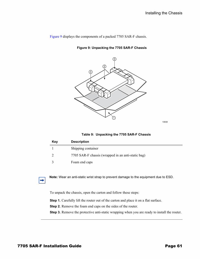
Installing the Chassis
7705 SAR-F Installation Guide Page 61
Figure 9 displays the components of a packed 7705 SAR-F chassis.
To unpack the chassis, open the carton and follow these steps:
Step 1. Carefully lift the router out of the carton and place it on a flat surface. Step 2. Remove the foam end caps on the sides of the router.Step 3. Remove the protective anti-static wrapping when you are ready to install the router.
Figure 9: Unpacking the 7705 SAR-F Chassis
1
19838
3
3
2
Table 9: Unpacking the 7705 SAR-F Chassis
Key Description
1 Shipping container
2 7705 SAR-F chassis (wrapped in an anti-static bag)
3 Foam end caps
Note: Wear an anti-static wrist strap to prevent damage to the equipment due to ESD.

Installing the Chassis
Page 62 7705 SAR-F Installation Guide
Installing the Chassis in a Rack
Rack-Mounting the ChassisThe 7705 SAR-F chassis is designed for installation in a 19-inch rack. The rack-mount brackets are factory-installed. Figure 10 illustrates the installation of the chassis in a rack.
Danger: Only trained and qualified personnel should install or replace this equipment.
Warnings: � Always wear an ESD-preventive wrist or ankle strap and always connect an ESD strap to
a nearby ground point that is connected to the site grounding point when working on the 7705 SAR-F. Typical ground points include the ground connection point on the front of the 7705 SAR-F, the grounding stud on the 7705 SAR-F mounting bracket, or a properly grounded rack or work bench.
� Failure to comply with the location requirements outlined in Installation Locations on page 52 and Chassis Location Requirements on page 52 will impede proper airflow and will result in thermal failure.
� Non-conductive coatings (such as lacquer and enamel) must be removed from threads and other contact surfaces to ensure electrical conductivity. Thread-forming screws with paint piercing washers may be used for this purpose during installation.
� When rack-mounting the chassis in an equipment rack, do not stack one 7705 SAR-F chassis or any other equipment directly on top of another 7705 SAR-F chassis, such that the bottom chassis is supporting other devices. Each chassis must be secured in the rack with the appropriate mounting apparatus.
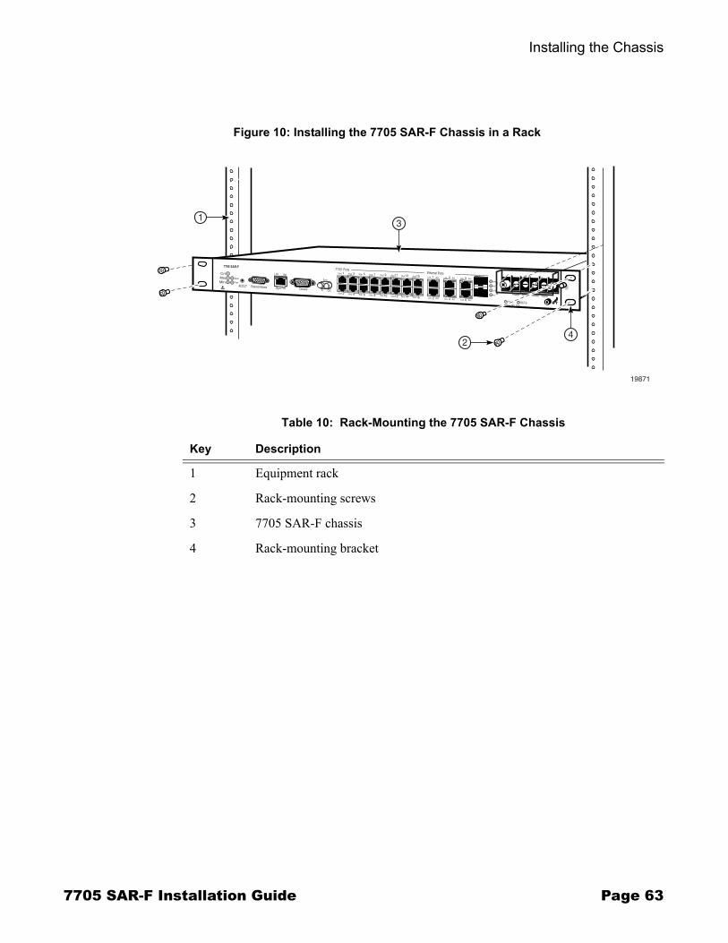
Installing the Chassis
7705 SAR-F Installation Guide Page 63
Figure 10: Installing the 7705 SAR-F Chassis in a Rack
1
19871
Cri
7705 SAR-F
MajMin
Stat
Pwr
ACO/LT External Alarms ConsoleMgmt Port
Link Act
T1/E1 Ports7Stat 11Stat 1Link Act
2Link Act
3Link Act
4Link Act
7
8
5Link Act
6Link Act
1Stat
2Stat
3Stat
4Stat
5Stat
6Stat 8Stat
9Stat
10Stat 12Stat
13Stat
14Stat
15Stat
16Stat
In Out
Sync
Ethernet Ports
Link
Act
Link
Act
BAT A BAT B
24
3
+BattA -BattA +BattB -BattB
-48V Batt
Table 10: Rack-Mounting the 7705 SAR-F Chassis
Key Description
1 Equipment rack
2 Rack-mounting screws
3 7705 SAR-F chassis
4 Rack-mounting bracket

Installing the Chassis
Page 64 7705 SAR-F Installation Guide
Before you begin, verify that:
� the equipment rack is securely installed, anchored, and grounded. Refer to the rack manufacturer�s documentation for instructions.
� the power to the rack is OFF
Required tools:
� a Phillips screwdriver
To install the chassis in the rack:
Step 1. Lift the 7705 SAR-F and position it in the rack. Step 2. Align the mounting holes on each bracket with the mounting holes on the rack
upright. Insert a screw into each mounting hole and tighten each screw.
Step 3. Ground the chassis to the building ground. See Chassis Ground Wiring on page 65.

Installing the Chassis
7705 SAR-F Installation Guide Page 65
Chassis Ground WiringTo ensure that the equipment is connected to earth ground, use the following instructions to prepare the ground wire and make the connection. The ground wire is not provided. The length of the ground wire depends on the location of the router and proximity to the proper grounding facilities.
Making the Ground Connection Tools and hardware required:
� wire stripper� wire cutter� crimping tool� torque driver for hex nut� M4 ring lug� minimum #18 AWG wire (green/yellow)
Caution: The 7705 SAR-F chassis ground stud located on the right-hand side mounting bracket must be a single-purpose permanent connection to the earth (building) ground point. Therefore, the connection requires its own nut and washer.
Notes: � When wiring the unit, the chassis ground connection must always be made first and
disconnected last.� All bare conductors must be coated with an appropriate antioxidant compound before
crimp connections are made. All unplated connectors, braided strap, and bus bars must be brought to a bright finish and then coated with an antioxidant before connecting them.
� All surfaces that are used for intentionally grounding the 7705 SAR-F must be brought to a bright finish, and an antioxidant solution must be applied to the surfaces being joined.
Figure 11: Preparing the Ground Wire
3
2
1
19641
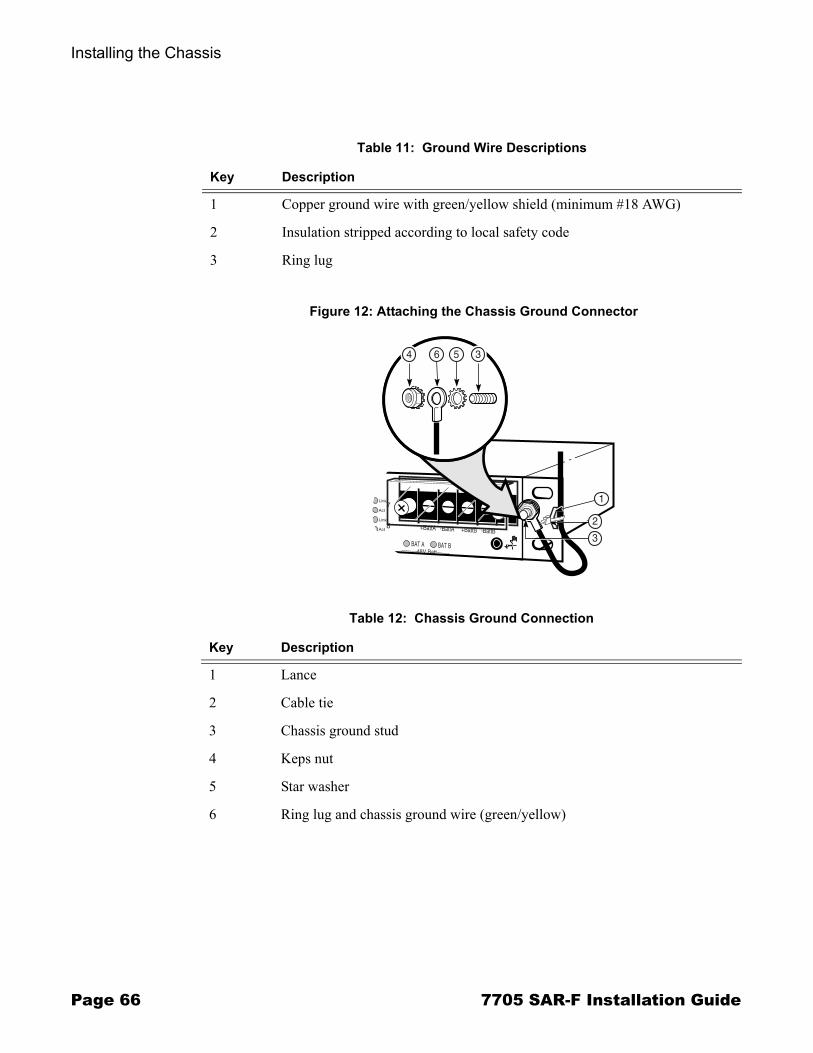
Installing the Chassis
Page 66 7705 SAR-F Installation Guide
Table 11: Ground Wire Descriptions
Key Description
1 Copper ground wire with green/yellow shield (minimum #18 AWG)
2 Insulation stripped according to local safety code
3 Ring lug
Figure 12: Attaching the Chassis Ground Connector
Table 12: Chassis Ground Connection
Key Description
1 Lance
2 Cable tie
3 Chassis ground stud
4 Keps nut
5 Star washer
6 Ring lug and chassis ground wire (green/yellow)
7
8
Link
Act
Link
Act
BAT A
2
1
4 56 3
7
8
BAT B
+BattA -BattA +BattB -BattB
-48V Batt
3
Installing the Chassis
7705 SAR-F Installation Guide Page 67
To make the chassis ground connection:
Step 1. Run a single length of #18 AWG wire (minimum) from the ground point (building ground or equipment ground bus) to the chassis ground stud. When routing the cable, ensure that there is enough extra wire to form a service loop at the chassis end in order to facilitate maintenance.
Step 2. Using a wire-stripping tool, strip the insulation from the wire according to local safety codes and crimp the ring lug to the wire (Figure 11).
Step 3. Remove the Keps nut and star washer from the ground stud on the mounting bracket.Step 4. Place a star washer and the ring lug on the ground stud such that the wire is angled
slightly as it runs down the rack upright (Figure 12). Secure the lug with the Keps nut. Tighten the nut to a torque of 8-10 lbf-in maximum. Do not over-tighten.
Step 5. Use a cable tie to secure the ground wire to the lance on the mounting bracket.Step 6. Form a service loop with the extra wire and secure it to a convenient place (for
example, a rack upright).Step 7. Connect the opposite end of the ground wire to the appropriate ground point at your
installation site. Ensure that the chassis ground connection is made according to local safety codes.
Step 8. Connect the 7705 SAR-F to the DC power source. See DC Power Connections on page 69.
Installing the Chassis
Page 68 7705 SAR-F Installation Guide

7705 SAR-F Installation Guide Page 69
DC Power Connections
In This ChapterThis chapter provides information about wiring and connecting the DC power source to the 7705 SAR-F:
� Wiring and Connecting DC Power on page 70→ Warnings and Notes on page 70
� DC-Input Power Connections on page 71→ Wiring the DC Inputs on page 71
DC Power Connections
Page 70 7705 SAR-F Installation Guide
Wiring and Connecting DC Power
Warnings and Notes
Dangers: � Only qualified personnel should install or replace this equipment. � Confirm that the DC power source is OFF during installation. The power source should be
a safety extra-low voltage (SELV) source.� Turn OFF power at the power source before you install or remove power cables or cords. � The unit should be connected to a DC branch circuit with a minimum 5 A and maximum
10 A circuit breaker or fuse that meets the requirements for branch circuit protection. A suitable disconnect device must be provided in the DC branch, either a circuit breaker or switch that can be employed to disconnect power to the system during servicing.
� Before working on equipment that is connected to power, remove jewelry, such as rings, necklaces, and watches. When metal objects are in contact with power and ground, serious burns can occur or the objects can be welded to the terminals.
� You must use cables that meet local electrical code requirements.
Warnings: � Do not install equipment that appears to be damaged.� The router and equipment rack must be properly grounded. Electrostatic discharge (ESD)
damage can occur if components are mishandled. � Always wear an ESD-preventive wrist or ankle strap and always connect an ESD strap to
a nearby ground point that is connected to the site grounding point when working on the 7705 SAR-F. Typical ground points include the ground connection point on the front of the 7705 SAR-F, the grounding stud on the 7705 SAR-F mounting bracket, or a properly grounded rack or work bench.
� For IBN installations, the battery return terminal(s) on the SAR-F must always be connected to the building ground at the power source. For redundant supply configurations, separate battery return wires must be used.
� For CBN installations, the battery return terminal should be connected to chassis ground at the chassis or frame.
Notes: � The 7705 SAR-F requires a minimum of one DC power source to operate, but using two
DC power sources is recommended for redundancy.� The 7705 SAR-F is suitable for both DC-I and DC-C power configurations. � All bare conductors must be coated with an appropriate antioxidant compound before
crimp connections are made. All unplated connectors, braided strap, and bus bars must be brought to a bright finish and then coated with an antioxidant before connecting them.
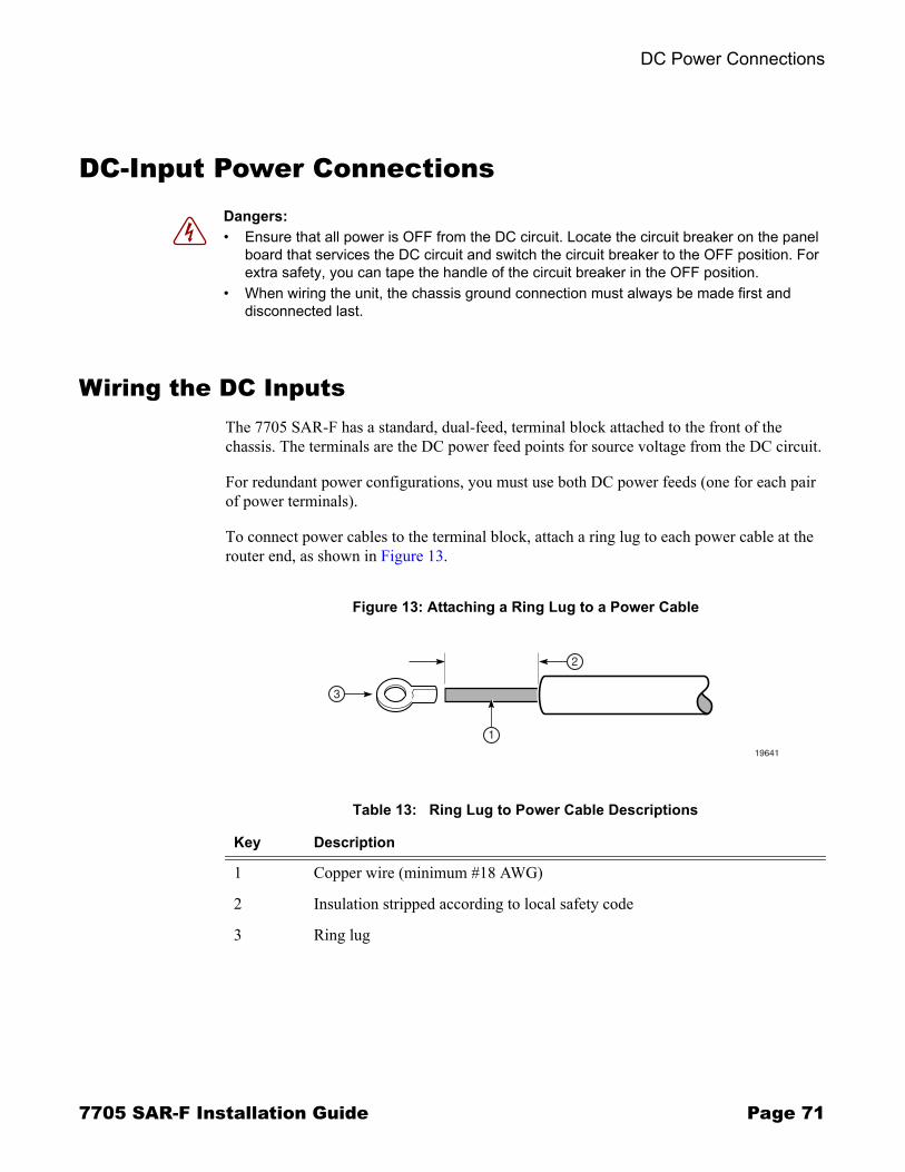
DC Power Connections
7705 SAR-F Installation Guide Page 71
DC-Input Power Connections
Wiring the DC Inputs The 7705 SAR-F has a standard, dual-feed, terminal block attached to the front of the chassis. The terminals are the DC power feed points for source voltage from the DC circuit.
For redundant power configurations, you must use both DC power feeds (one for each pair of power terminals).
To connect power cables to the terminal block, attach a ring lug to each power cable at the router end, as shown in Figure 13.
Dangers: � Ensure that all power is OFF from the DC circuit. Locate the circuit breaker on the panel
board that services the DC circuit and switch the circuit breaker to the OFF position. For extra safety, you can tape the handle of the circuit breaker in the OFF position.
� When wiring the unit, the chassis ground connection must always be made first and disconnected last.
Figure 13: Attaching a Ring Lug to a Power Cable
Table 13: Ring Lug to Power Cable Descriptions
Key Description
1 Copper wire (minimum #18 AWG)
2 Insulation stripped according to local safety code
3 Ring lug
3
2
1
19641
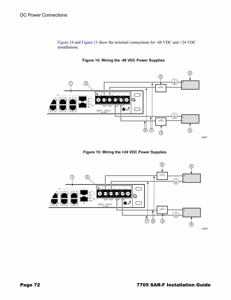
DC Power Connections
Page 72 7705 SAR-F Installation Guide
Figure 14 and Figure 15 show the terminal connections for -48 VDC and +24 VDC installations.
Figure 14: Wiring the -48 VDC Power Supplies
Figure 15: Wiring the +24 VDC Power Supplies
7+BattB -BattB
1Link Act
2Link Act
3Link Act
4Link Act
5Link Act
6Link Act
Ethernet PortsLink
Act
Link
Act
19957
1 2
6 7
3
7
8
BAT A BAT B
+BattA -BattA
-48V Batt
4
+_
53
+_
7-BattA +BattB -BattB
1Link Act
2Link Act
3Link Act
4Link Act
5
8
Link Act
6Link Act
Ethernet PortsLink
Act
Link
Act
19853
1 2
7
3
7
7
8
BAT A BAT B
+BattA
+24 Batt
4
53
+_
+_
6
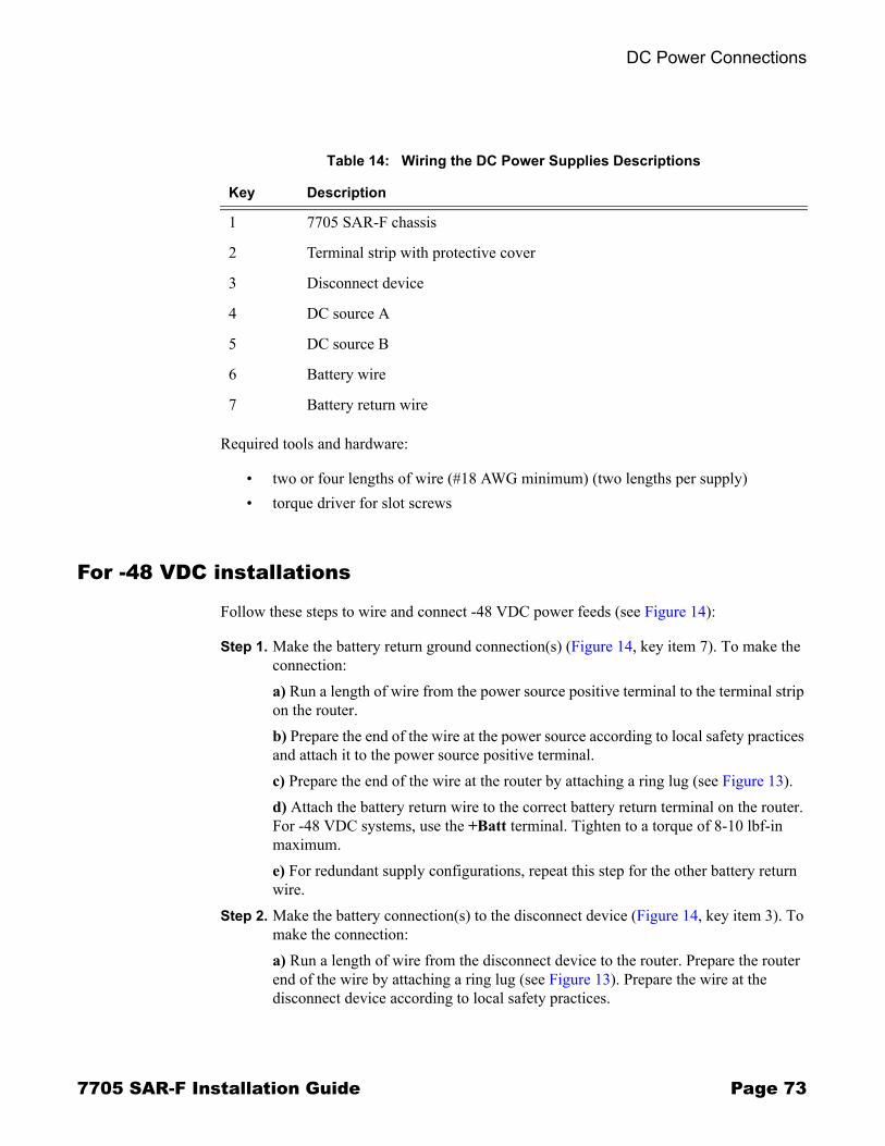
DC Power Connections
7705 SAR-F Installation Guide Page 73
Required tools and hardware:
� two or four lengths of wire (#18 AWG minimum) (two lengths per supply) � torque driver for slot screws
For -48 VDC installations
Follow these steps to wire and connect -48 VDC power feeds (see Figure 14):
Step 1. Make the battery return ground connection(s) (Figure 14, key item 7). To make the connection:a) Run a length of wire from the power source positive terminal to the terminal strip on the router. b) Prepare the end of the wire at the power source according to local safety practices and attach it to the power source positive terminal. c) Prepare the end of the wire at the router by attaching a ring lug (see Figure 13).d) Attach the battery return wire to the correct battery return terminal on the router. For -48 VDC systems, use the +Batt terminal. Tighten to a torque of 8-10 lbf-in maximum. e) For redundant supply configurations, repeat this step for the other battery return wire.
Step 2. Make the battery connection(s) to the disconnect device (Figure 14, key item 3). To make the connection:a) Run a length of wire from the disconnect device to the router. Prepare the router end of the wire by attaching a ring lug (see Figure 13). Prepare the wire at the disconnect device according to local safety practices.
Table 14: Wiring the DC Power Supplies Descriptions
Key Description
1 7705 SAR-F chassis
2 Terminal strip with protective cover
3 Disconnect device
4 DC source A
5 DC source B
6 Battery wire
7 Battery return wire

DC Power Connections
Page 74 7705 SAR-F Installation Guide
b) Attach the battery wire to the correct battery terminal on the router. For -48 VDC systems, use the -Batt terminal. Tighten to a torque of 8-10 lbf-in maximum.c) Attach the battery wire to the disconnect device.d) For redundant supply configurations, repeat this step for the other battery wire.
Step 3. Check that the DC supply wiring is correct.Step 4. Install the SFPs. See SFPs on page 75.
For +24 VDC installations
Follow these steps to wire and connect +24 VDC power feeds (see Figure 15):
Step 1. Make the battery return ground connection(s) (Figure 15, key item 7). To make the connection:a) Run a length of wire from the power source negative terminal to the terminal strip on the router.b) Prepare the end of the wire at the power source according to local safety practices and attach it to the power source negative terminal. c) Prepare the end of the wire at the router by attaching a ring lug (see Figure 13).d) Attach the battery return wire to the correct battery return terminal on the router. For +24 VDC systems, use the -Batt terminal. Tighten to a torque of 8-10 lbf-in maximum. e) For redundant supply configurations, repeat this step for the other battery return wire.
Step 2. Make the battery connection(s) to the disconnect device (Figure 15, key item 3). To make the connection:a) Run a length of wire from the disconnect device to the router. Prepare the router end of the wire by attaching a ring lug (see Figure 13). Prepare the wire at the disconnect device according to local safety practices.b) Attach the battery wire to the correct battery terminal on the router. For +24 VDC systems, use the +Batt terminal. Tighten to a torque of 8-10 lb-in maximum.c) Attach the battery wire to the disconnect device.d) For redundant supply configurations, repeat this step for the other battery wire.
Step 3. Check that the DC supply wiring is correct.Step 4. Install the SFPs. See SFPs on page 75.
7705 SAR-F Installation Guide Page 75
SFPs
In This ChapterThis chapter provides information about installing and removing SFPs in the 7705 SAR-F:
� Installing and Removing SFPs on page 76→ Warnings and Notes on page 76→ SFPs on page 77→ Fiber Cable Preparation on page 78→ Locking and Release Mechanisms on page 78→ SFP Support on page 79→ Installing SFPs on page 80→ Removing SFPs on page 80
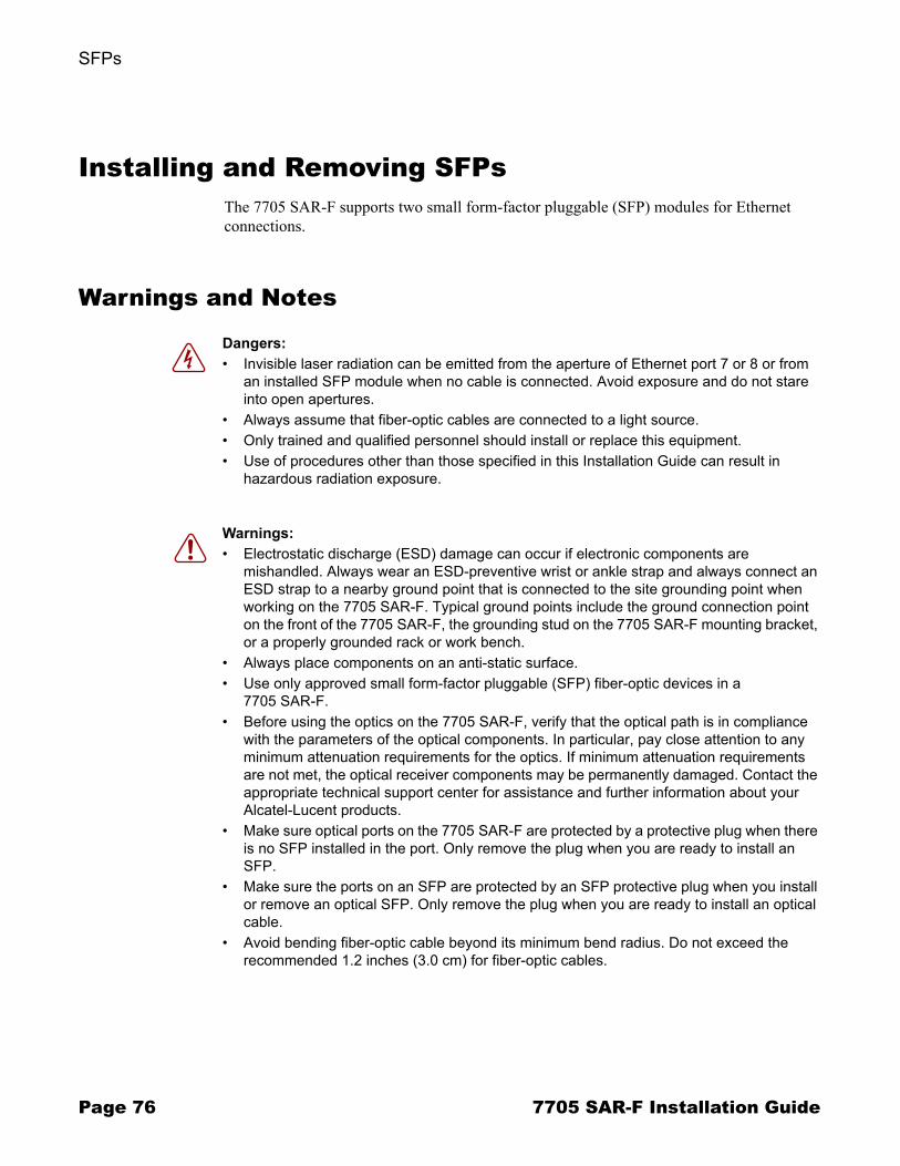
SFPs
Page 76 7705 SAR-F Installation Guide
Installing and Removing SFPsThe 7705 SAR-F supports two small form-factor pluggable (SFP) modules for Ethernet connections.
Warnings and Notes
Dangers: � Invisible laser radiation can be emitted from the aperture of Ethernet port 7 or 8 or from
an installed SFP module when no cable is connected. Avoid exposure and do not stare into open apertures.
� Always assume that fiber-optic cables are connected to a light source.� Only trained and qualified personnel should install or replace this equipment.� Use of procedures other than those specified in this Installation Guide can result in
hazardous radiation exposure.
Warnings: � Electrostatic discharge (ESD) damage can occur if electronic components are
mishandled. Always wear an ESD-preventive wrist or ankle strap and always connect an ESD strap to a nearby ground point that is connected to the site grounding point when working on the 7705 SAR-F. Typical ground points include the ground connection point on the front of the 7705 SAR-F, the grounding stud on the 7705 SAR-F mounting bracket, or a properly grounded rack or work bench.
� Always place components on an anti-static surface.� Use only approved small form-factor pluggable (SFP) fiber-optic devices in a
7705 SAR-F.� Before using the optics on the 7705 SAR-F, verify that the optical path is in compliance
with the parameters of the optical components. In particular, pay close attention to any minimum attenuation requirements for the optics. If minimum attenuation requirements are not met, the optical receiver components may be permanently damaged. Contact the appropriate technical support center for assistance and further information about your Alcatel-Lucent products.
� Make sure optical ports on the 7705 SAR-F are protected by a protective plug when there is no SFP installed in the port. Only remove the plug when you are ready to install an SFP.
� Make sure the ports on an SFP are protected by an SFP protective plug when you install or remove an optical SFP. Only remove the plug when you are ready to install an optical cable.
� Avoid bending fiber-optic cable beyond its minimum bend radius. Do not exceed the recommended 1.2 inches (3.0 cm) for fiber-optic cables.

SFPs
7705 SAR-F Installation Guide Page 77
SFPsA small form-factor pluggable (SFP) module can be installed in Ethernet ports 7 and 8. Figure 16 illustrates the installation of an SFP.
Refer to SFP Support on page 79 for a list of SFPs supported by the router.
Cautions: � Make sure the connector on the fiber cable is protected by a dust cover until you are
ready to attach the cable to an SFP. � Always replace the dust cover on the connector of a fiber cable when the cable is
disconnected from an SFP.
Notes: � Discard SFPs according to all local laws and regulations.� SFPs can be installed and replaced without disabling the Ethernet interfaces.� SFPs are keyed to prevent incorrect insertion. If an SFP is not seated properly, remove it
and confirm that the orientation is correct before reinserting it.
Figure 16: Installing an SFP
19854
Cri
7705 SAR-F
MajMin
Stat
Pwr
ACO/LT External Alarms Mgmt Port Console
Link Act
In Out
1T1/E1 Ports
Stat 3Stat 5Stat 7Stat 9Stat 11Stat 13Stat 15Stat 1Link Act
2Link Act
3Link Act
4Link Act
57
8
Link Act
6Link Act2Stat 4Stat 6Stat 8Stat 10Stat 12Stat 14Stat 16Stat
Sync
Ethernet Ports
Link
Act
Link
Act
BAT A BAT B
+BattA -BattA +BattB -BattB
-48V Batt
5LinkAct
6Link
Act
3Act
4Link
Act
Act
7
8
Link
Act
Link
Act
1
2

SFPs
Page 78 7705 SAR-F Installation Guide
Fiber Cable PreparationClean the connector on the fiber cable before inserting it into the SFP to prevent transferring small particles and contaminating the transceiver.
If you switch SFPs from one port to another, ensure that you clean the fiber connectors before reinserting them.
Apply high standards when inspecting and cleaning fiber connectors. Use a �dry� cleaning method to clean fiber connectors.
Locking and Release MechanismsSFPs approved by Alcatel-Lucent can use different lock and release methods. Possible lock and release mechanisms include:
� locking handle�a locking handle or lever on the front of the SFP that you gently raise or lower to insert or remove the SFP from the port
� bail�a bar or latch in the front of the SFP that you pull down and outward to release the module
� tabs�tabs on the sides of the SFP that you press inward to release the module
Table 15: SFP Installation Features
Key Description
1 SFP receptacle
2 SFP
Caution: Improper handling, cleaning, and inspection techniques can compromise the fiber connection, resulting in data transmission errors. Refer to Alcatel-Lucent�s Online Support Documentation Service (OSDS) (http://www.alcatel-lucent.com/support) for the Optical Handling Reference Guide.
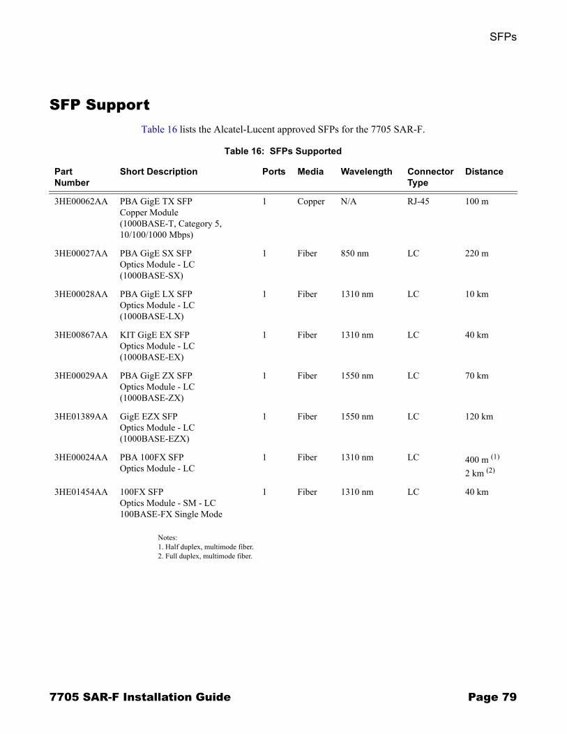
SFPs
7705 SAR-F Installation Guide Page 79
SFP SupportTable 16 lists the Alcatel-Lucent approved SFPs for the 7705 SAR-F.
Notes:1. Half duplex, multimode fiber.2. Full duplex, multimode fiber.
Table 16: SFPs Supported
Part Number
Short Description Ports Media Wavelength Connector Type
Distance
3HE00062AA PBA GigE TX SFP Copper Module(1000BASE-T, Category 5, 10/100/1000 Mbps)
1 Copper N/A RJ-45 100 m
3HE00027AA PBA GigE SX SFP Optics Module - LC(1000BASE-SX)
1 Fiber 850 nm LC 220 m
3HE00028AA PBA GigE LX SFP Optics Module - LC(1000BASE-LX)
1 Fiber 1310 nm LC 10 km
3HE00867AA KIT GigE EX SFP Optics Module - LC(1000BASE-EX)
1 Fiber 1310 nm LC 40 km
3HE00029AA PBA GigE ZX SFP Optics Module - LC(1000BASE-ZX)
1 Fiber 1550 nm LC 70 km
3HE01389AA GigE EZX SFP Optics Module - LC(1000BASE-EZX)
1 Fiber 1550 nm LC 120 km
3HE00024AA PBA 100FX SFP Optics Module - LC
1 Fiber 1310 nm LC 400 m (1)
2 km (2)
3HE01454AA 100FX SFP Optics Module - SM - LC 100BASE-FX Single Mode
1 Fiber 1310 nm LC 40 km
SFPs
Page 80 7705 SAR-F Installation Guide
Installing SFPsTo install an SFP:
Step 1. Remove the SFP from the packaging and place it on a flat anti-static work surface.Step 2. Hold the SFP by its sides and insert it into the appropriate port until it clicks into
place.Step 3. For optical SFPs, remove the protective plug from the SFP port when you are ready
to attach the fiber cable.
Removing SFPsWhen you are removing an SFP, have the following parts ready:
� a replacement SFP or protective plug for the empty Ethernet port� a protective plug for the SFP � a dust cover for the fiber cable connector� an anti-static mat or electrostatic bag
To remove an SFP:
Step 1. Disconnect the cable from the SFP connector.Step 2. Release the locking mechanism on the SFP with your thumb and forefinger. See
Locking and Release Mechanisms on page 78 for descriptions of the different SFP lock and release methods. Slide the SFP out of the port.
Step 3. Place the SFP on an anti-static mat or in an electrostatic bag.Step 4. Install a replacement SFP or insert a protective plug into the Ethernet port.Step 5. Connect the fiber or copper cable, or insert a protective plug into the optical port and
place a dust cover on the fiber cable connector.

7705 SAR-F Installation Guide Page 81
Connecting Cables
In This ChapterThis chapter provides information about connecting cables to the 7705 SAR-F:
� Warnings and Notes on page 82� Making Cable Connections to Ports on page 83
→ Warnings and Notes on page 83� Cable Connections on page 84
→ Ethernet and Copper Cables on page 84→ Fiber Cables on page 85→ Shield Ground Connections on page 86
� Making External Synchronization Connections on page 87→ Connecting an External Synchronization Input on page 87→ Providing an External Synchronization Output on page 87
� Making External Alarm Connections on page 88→ Connecting an External Alarm on page 89
� Making Router Management Connections on page 90
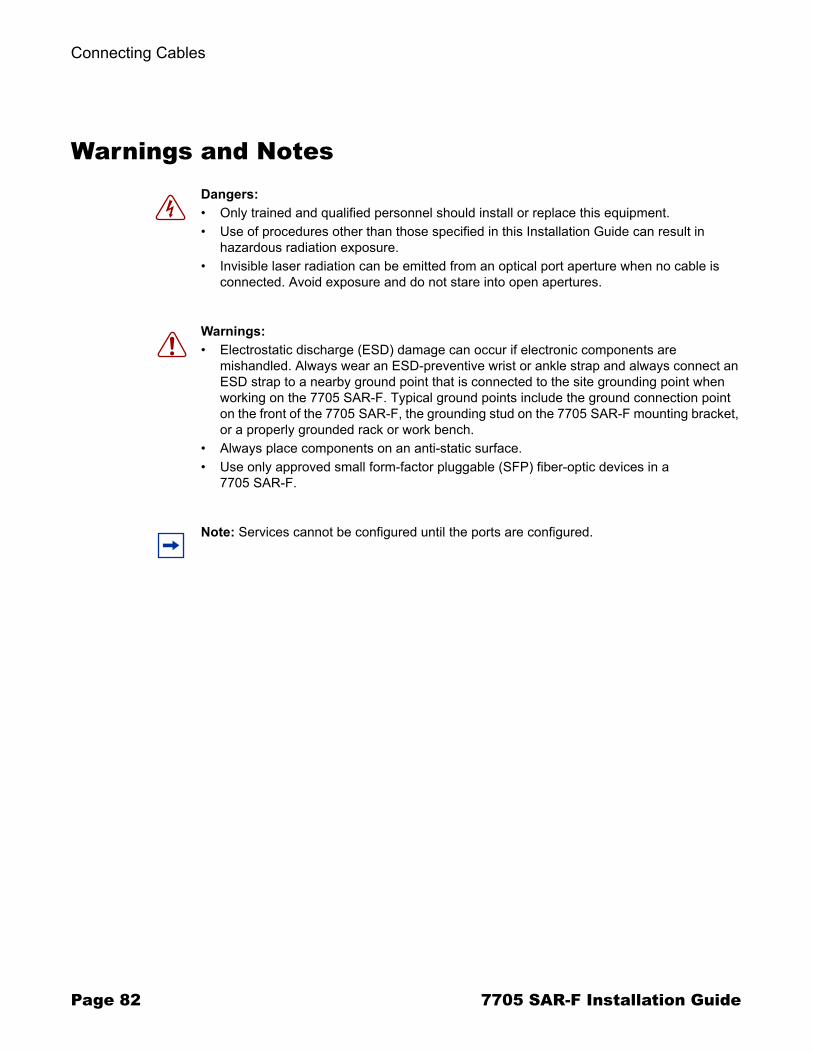
Connecting Cables
Page 82 7705 SAR-F Installation Guide
Warnings and NotesDangers: � Only trained and qualified personnel should install or replace this equipment.� Use of procedures other than those specified in this Installation Guide can result in
hazardous radiation exposure.� Invisible laser radiation can be emitted from an optical port aperture when no cable is
connected. Avoid exposure and do not stare into open apertures.
Warnings: � Electrostatic discharge (ESD) damage can occur if electronic components are
mishandled. Always wear an ESD-preventive wrist or ankle strap and always connect an ESD strap to a nearby ground point that is connected to the site grounding point when working on the 7705 SAR-F. Typical ground points include the ground connection point on the front of the 7705 SAR-F, the grounding stud on the 7705 SAR-F mounting bracket, or a properly grounded rack or work bench.
� Always place components on an anti-static surface.� Use only approved small form-factor pluggable (SFP) fiber-optic devices in a
7705 SAR-F.
Note: Services cannot be configured until the ports are configured.
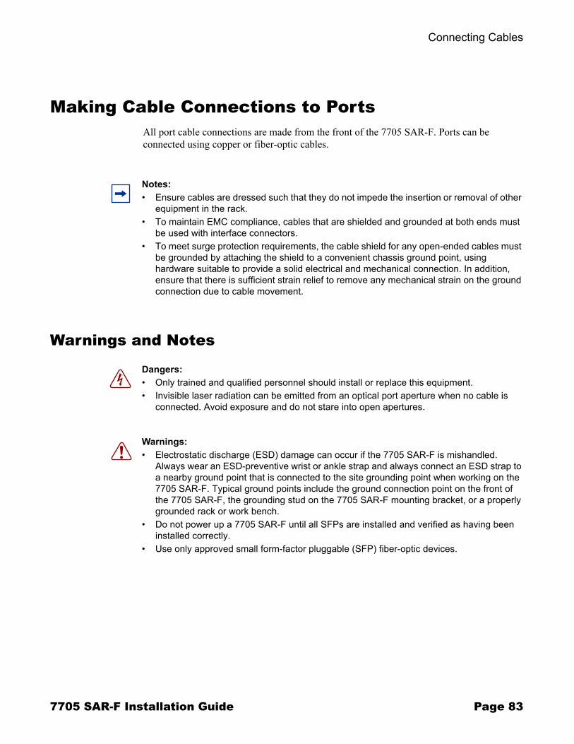
Connecting Cables
7705 SAR-F Installation Guide Page 83
Making Cable Connections to PortsAll port cable connections are made from the front of the 7705 SAR-F. Ports can be connected using copper or fiber-optic cables.
Warnings and Notes
Notes: � Ensure cables are dressed such that they do not impede the insertion or removal of other
equipment in the rack.� To maintain EMC compliance, cables that are shielded and grounded at both ends must
be used with interface connectors.� To meet surge protection requirements, the cable shield for any open-ended cables must
be grounded by attaching the shield to a convenient chassis ground point, using hardware suitable to provide a solid electrical and mechanical connection. In addition, ensure that there is sufficient strain relief to remove any mechanical strain on the ground connection due to cable movement.
Dangers: � Only trained and qualified personnel should install or replace this equipment.� Invisible laser radiation can be emitted from an optical port aperture when no cable is
connected. Avoid exposure and do not stare into open apertures.
Warnings: � Electrostatic discharge (ESD) damage can occur if the 7705 SAR-F is mishandled.
Always wear an ESD-preventive wrist or ankle strap and always connect an ESD strap to a nearby ground point that is connected to the site grounding point when working on the 7705 SAR-F. Typical ground points include the ground connection point on the front of the 7705 SAR-F, the grounding stud on the 7705 SAR-F mounting bracket, or a properly grounded rack or work bench.
� Do not power up a 7705 SAR-F until all SFPs are installed and verified as having been installed correctly.
� Use only approved small form-factor pluggable (SFP) fiber-optic devices.

Connecting Cables
Page 84 7705 SAR-F Installation Guide
Cable Connections
Ethernet and Copper CablesFigure 17 illustrates how Ethernet and copper wire cables are routed on the 7705 SAR-F. Cables can be routed to the left or the right of the chassis.
Hardware required:
� cable ties (optional)
To attach Ethernet and copper wire cables:
Step 1. Attach the cable to the port connector on the front of the 7705 SAR-F.Step 2. Route the cables to the left or the right of the chassis. If desired, loosely bundle the
cables together using a cable tie. Do not over-tighten the cable tie.
Step 3. Attach the other end of the cable to the attached equipment.
Figure 17: Managing Cable Connections
Note: Arrange the cables such that they do not impede the insertion or removal of other equipment mounted in the rack.
Cri
7705 SAR-F
MajMin
Stat
Pwr
ACO/LT External AlarmsConsole
Mgmt Port
Link ActT1/E1 Ports
7St-t 11St-t1Link Act
2Link Act
3Link Act
4Link Act
5Link Act
6Link Act
1St-t
2St-t
3St-t
4St-t
5St-t
6St-t 8St-t
9St-t
10St-t 12St-t
13St-t
14St-t
15St-t
16St-t
In Out
Sync
Ethernet Ports
Link
Act
Link
Act
Cri
7705 SAR-F
MajMin
Stat
Pwr
ACO/LT External Alarms ConsoleMgmt Port
Link Act
T1/E1 Ports7St-t 11St-t 1Link Act
2Link Act
3Link Act
4Link Act
7
8
5Link Act
6Link Act
1St-t
2St-t
3St-t
4St-t
5St-t
6St-t 8St-t
9St-t
10St-t 12St-t
13St-t
14St-t
15St-t
16St-t
In Out
Sync
Ethernet Ports
Link
Act
Link
Act
Cri
7705 SAR-F
MajMin
Stat
Pwr
ACO/LT External Alarms ConsoleMgmt Port
Link Act
T1/E1 Ports7St-t 11St-t 1Link Act
2Link Act
3Link Act
4Link Act
75Link Act
6Link Act
1St-t
2St-t
3St-t
4St-t
5St-t
6St-t 8St-t
9St-t
10St-t 12St-t
13St-t
14St-t
15St-t
16St-t
In Out
Sync
Ethernet Ports
Link
Act
Link
Act
19876
7
8
BAT A BAT B
+BattA -BattA +BattB -BattB
-48V Batt
7
8
BAT A BAT B
+BattA -BattA +BattB -BattB
-48V Batt
7
8
BAT A BAT B
+BattA -BattA +BattB -BattB
-48V Batt
Connecting Cables
7705 SAR-F Installation Guide Page 85
Fiber Cables
Fiber-optic cables are routed in a similar fashion to Ethernet and copper wire cables (see Figure 17). Cables are routed to the left or the right of the chassis.
Hardware required:
� fiber cable boot (optional)� cable ties (optional)
To attach fiber cables:
Step 1. Attach the cable to the SFP port connector on the front of the router. If necessary, attach the fiber cable boot according to the manufacturer�s instructions.
Step 2. Route the cables to the left or the right of the chassis. If desired, loosely bundle the cables together using a cable tie. Do not over-tighten the cable tie.
Step 3. Attach the other end of the fiber cable to the attached equipment.
Warnings: � Fiber cables are sensitive to bending, twisting and general over-exertion. Extreme
caution is recommended when handling fiber cable.� In order to ensure that the minimum fiber bend radius of 1.2 in. (3.0 cm) is maintained
within the allowable space, an open-angled 90º boot such as TYCO 1374737-x or equivalent is recommended. The boots must be installed and oriented during fiber termination.
� Observe proper fiber connector handling with respect to the use of dust covers and cleaning.
Warning: Fiber cables are sensitive to bending, twisting and general over-exertion. Extreme caution is recommended when handling fiber cable.
Note: Arrange the cables such that they do not impede the insertion or removal of other equipment in the rack.

Connecting Cables
Page 86 7705 SAR-F Installation Guide
Shield Ground ConnectionsTo maintain EMC compliance, cables that are shielded and grounded at both ends must be used with all the electrical interfaces on the router.
To meet surge protection requirements, the shield of any open-ended cable must be grounded to a convenient chassis ground point, such as the equipment rack.
Hardware required:
� wire stripper� hardware for making the connection (such as a screw, star washer, and cable ties)
To make a shield ground connection:
Step 1. Locate a convenient chassis ground point, such as the equipment rack.Step 2. Carefully strip enough insulation (outer jacket) from the cable such that the exposed
grounding wire can reach the chassis ground point. Ensure that there is enough stripped insulation to provide strain relief for the ground connection.
Step 3. Separate the ground shield (braid, foil, and drain wire) from the signal conductors.Step 4. Securely attach the shield to the chassis ground point. Use a screw and star washer
large enough to make a proper ground connection. Use proper cable dressing and strain relief techniques.
Caution: When stripping the cable insulation, avoid nicking the ground conductors or the insulation on the signal conductor. Nicks can weaken or break a conductor or expose a wire to a potential short circuit.
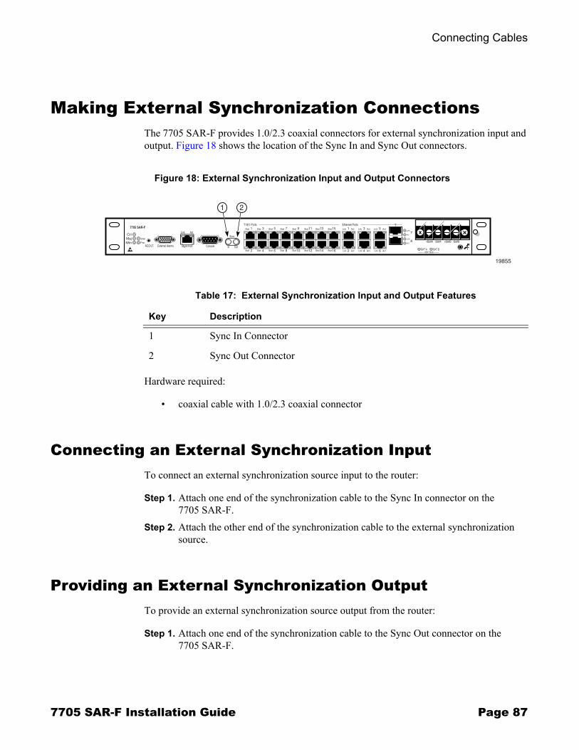
Connecting Cables
7705 SAR-F Installation Guide Page 87
Making External Synchronization ConnectionsThe 7705 SAR-F provides 1.0/2.3 coaxial connectors for external synchronization input and output. Figure 18 shows the location of the Sync In and Sync Out connectors.
Hardware required:
� coaxial cable with 1.0/2.3 coaxial connector
Connecting an External Synchronization InputTo connect an external synchronization source input to the router:
Step 1. Attach one end of the synchronization cable to the Sync In connector on the 7705 SAR-F.
Step 2. Attach the other end of the synchronization cable to the external synchronization source.
Providing an External Synchronization OutputTo provide an external synchronization source output from the router:
Step 1. Attach one end of the synchronization cable to the Sync Out connector on the 7705 SAR-F.
Figure 18: External Synchronization Input and Output Connectors
19855
7
Cri
7705 SAR-F
MajMin
Stat
Pwr
ACO/LT External Alarms Mgmt Port Console
Link Act
In Out
1T1/E1 Ports
Stat 3Stat 5Stat 7Stat 9Stat 11Stat 13Stat 15Stat 1Link Act
2Link Act
3Link Act
4Link Act
57
8
Link Act
6Link Act2Stat 4Stat 6Stat 8Stat 10Stat 12Stat 14Stat 16Stat
Sync
Ethernet Ports
Link
Act
Link
Act
BAT A BAT B
+BattA -BattA +BattB -BattB
-48V Batt
1 2
Table 17: External Synchronization Input and Output Features
Key Description
1 Sync In Connector
2 Sync Out Connector

Connecting Cables
Page 88 7705 SAR-F Installation Guide
Step 2. Attach the other end of the synchronization cable to the device requiring a synchronization source.
Making External Alarm ConnectionsThe 7705 SAR-F provides a DB15 female connector for external alarm connections. The input and output ratings are 5 VDC and 100 mA (source or sink).
The External Alarms interfaces are equipped with relays that can be used to trigger external alarm indicators. They also provide inputs that can be used to trigger the generation of alarms on the 7705 SAR-F that indicate environmental or external alarm conditions. Refer to External Alarms Port Pinouts on page 111 for pinout definitions.
Figure 19 shows the location of the External Alarms connector. Figure 20 shows the pin numbers. See External Alarms Port on page 110 for pinout designations.
Hardware required:
� appropriate cable with DB15 male connector at the router end and customized connector at external device(s) end
Figure 19: External Alarms Connector
Cri
7705 SAR-F
MajMin
Stat
Pwr
ACO/LT External Alarms Mgmt Port Console
Link Act
In Out
1T1/E1 Ports
Stat 3Stat 5Stat 7Stat 9Stat 11Stat 13Stat 15Stat 1Link Act
2Link Act
3Link Act
4Link Act
57
8
Link Act
6Link Act2Stat 4Stat 6Stat 8Stat 10Stat 12Stat 14Stat 16Stat
Sync
Ethernet Ports
Link
Act
Link
Act
BAT A BAT B
+BattA -BattA +BattB -BattB
-48V Batt
19856
External Alarms
Figure 20: External Alarms Connector Pin Numbers
10 6
15 11
15
19857
Connecting Cables
7705 SAR-F Installation Guide Page 89
Connecting an External Alarm To connect an external alarm to the router:
Step 1. Design the external alarm circuitry using the input and output pin assignments provided in External Alarms Port on page 110.
Step 2. Attach each alarm device to the customized end of the external alarm cable (either directly or through a distribution device).
Step 3. Attach the DB15 male connector end of the cable to the router.
Connecting Cables
Page 90 7705 SAR-F Installation Guide
Making Router Management ConnectionsRefer to Establishing Router Management Connections on page 95 for detailed information.
7705 SAR-F Installation Guide Page 91
Initializing and Provisioning
In This ChapterThis chapter provides information about initializing and provisioning the router:
� Powering Up the Router on page 92→ Power-Up and Initialization on page 92→ Troubleshooting Initial Startup on page 93
� Establishing Router Management Connections on page 95→ Console Connection on page 95→ Telnet Connection on page 96→ Running Telnet on page 97
� Provisioning the 7705 SAR-F on page 98

Initializing and Provisioning
Page 92 7705 SAR-F Installation Guide
Powering Up the RouterComplete the steps in Wiring the DC Inputs on page 71 and SFPs on page 75 before proceeding with the following instructions. Then power up the system and verify the LED activity of all components.
The primary copy of the 7705 SAR-F TiMOS software is located on the compact flash memory device that is factory-installed. The compact flash device is not user-accessible or field-replaceable.
Power-Up and InitializationTo power up the router, follow these steps:
Step 1. Turn ON the power to the router at the remote DC power source(s) to initiate the boot process. The Power LED should be blue, and the Bat A and Bat B LEDs should be green. If only one DC power source is used, only one Bat LED should be lit.
Step 2. Verify that the system is initializing. The system searches the compact flash device for the boot.ldr file (also known as the bootstrap or boot loader file). The Status and Activity LEDs blink green during initialization. After initialization (approximately 30 seconds), the Status and Activity LEDs turn solid green.If the LEDs do not operate as described above, or if they blink and turn off, refer to Troubleshooting Initial Startup on page 93.
Notes: � The DC-powered 7705 SAR-F does not have a power switch or circuit breaker. The
system is powered on by applying power from the DC power source. Typically, this is done via a circuit breaker or a disconnect device.
� Configurations and executable software can be stored on the compact flash memory device or at an FTP file location.
� You must have a console or Telnet connection to communicate with and provision the 7705 SAR-F. See Establishing Router Management Connections on page 95.

Initializing and Provisioning
7705 SAR-F Installation Guide Page 93
Step 3. Verify the operational status of the ports by checking the LEDs on the front of the router. Refer to 7705 SAR-F Connectors and LEDs on page 102.
Step 4. After verifying the LEDs, establish communication with the router via the Console port. Refer to Console Connection on page 95.
Step 5. (Optional at this time) Assign an IP address to the router. Refer to Telnet Connection on page 96 for quick reference information and to the 7705 SAR OS Basic System Configuration Guide for detailed information.
Step 6. (Optional at this time) Configure or modify the primary, secondary, or tertiary BOF file locations. Refer to Telnet Connection on page 96 for quick reference information and to the 7705 SAR OS Basic System Configuration Guide for detailed information.
Troubleshooting Initial StartupIf the system cannot load or cannot find the boot.ldr file on the compact flash memory device (cf3), the system will reboot continuously in an attempt to successfully find and load the boot.ldr file. If this happens, the 7705 SAR-F should be replaced and the faulty router returned to Alcatel-Lucent. The example below displays the output when the boot.ldr file cannot be found.
Example: Rebooting display
Rebooting...Alcatel-Lucent 7705 Boot ROM. Copyright 2007 Alcatel-Lucent.All rights reserved. All use is subject to applicable license agreements.Build: X-1.1.S13 on Wed Aug 27 21:48:25 EDT 2008 by csabuildVersion: 0x20Performing Data Bus Test... Passed.Performing Local RAM Test (1st 2MB)... Passed.COLD boot on processor #1CPLD revision is 0x0C?Preparing for jump to RAM...Starting bootrom RAM code...Bootrom version is v32 (0x20)CPU BIST check passed.Validating SDRAM from 0x41f00000 to 0x42000000Testing SDRAM from 0x02200000 to 0x41f00000Testing Compact Flash ... OK (SMART CF)CPLD revision is v12 (0x0c)Board Serial Number is 'NS083140278'Chassis Serial Number is 'NS083140278'Searching for boot.ldr on local drives:Searching cf3 for boot.ldr...Error - file boot.ldr not found on any drivePlease insert CF containing boot.ldr. Rebooting in 5 seconds.

Initializing and Provisioning
Page 94 7705 SAR-F Installation Guide
When the system finds the boot.ldr file, the system processes the initialization parameters from the BOF (boot option file). The BOF should be on the same drive as the boot.ldr file. If the BOF cannot be found or loaded, then the system prompts the user for alternate software and configuration file locations.
When the software is successfully loaded, control is passed from the boot loader file to the software. The runtime software attempts to locate the configuration file as configured in the BOF. The file includes configurations for the chassis, control and switching functions, and ports, as well as system, routing, and service configurations.
Figure 21 displays the compact flash directory structure and file names.
Files on the compact flash are:
� bof.cfg � Boot option file� boot.ldr � Bootstrap software� config.cfg � Default configuration file� TiMOS-m.n.Yz:
m � Major release numbern � minor release number
Y: A � Alpha release
B � Beta release
M � Maintenance release
R � Released softwarez � Version numberboth.tim � Application software file
Figure 21: Files on the Compact Flash
TiMOS-m.n.Yz
both.tim
config.cfgboot.ldrbof.cfg
Root
19644

Initializing and Provisioning
7705 SAR-F Installation Guide Page 95
Establishing Router Management ConnectionsThere are two ways to access management of the 7705 SAR-F:
� Console connection� Telnet connection
Console ConnectionThe console connector on the front of the 7705 SAR-F is a male DB9 connector (see Figure 22). To establish a console connection, you need the following:
� an ASCII terminal or a PC running terminal emulation software set to the parameters shown in Table 18
� a standard serial cable with a female DB9 connector
For pinout information, refer to Console Port Pinouts on page 110.
Table 18: Console Port Default Settings
Parameter Value
Baud Rate 115 200
Data Bits 8
Parity None
Stop Bits 1
Flow Control None
Figure 22: Console Port Connection
Cri
7705 SAR-F
MajMin
Stat
Pwr
ACO/LT External Alarms Mgmt Port Console
Link Act
In Out
1T1/E1 Ports
Stat 3Stat 5Stat 7Stat 9Stat 11Stat 13Stat 15Stat 1Link Act
2Link Act
3Link Act
4Link Act
57
8
Link Act
6Link Act2Stat 4Stat 6Stat 8Stat 10Stat 12Stat 14Stat 16Stat
Sync
Ethernet Ports
Link
Act
Link
Act
BAT A BAT B
+BattA -BattA +BattB -BattB
-48V Batt
19858
Console port
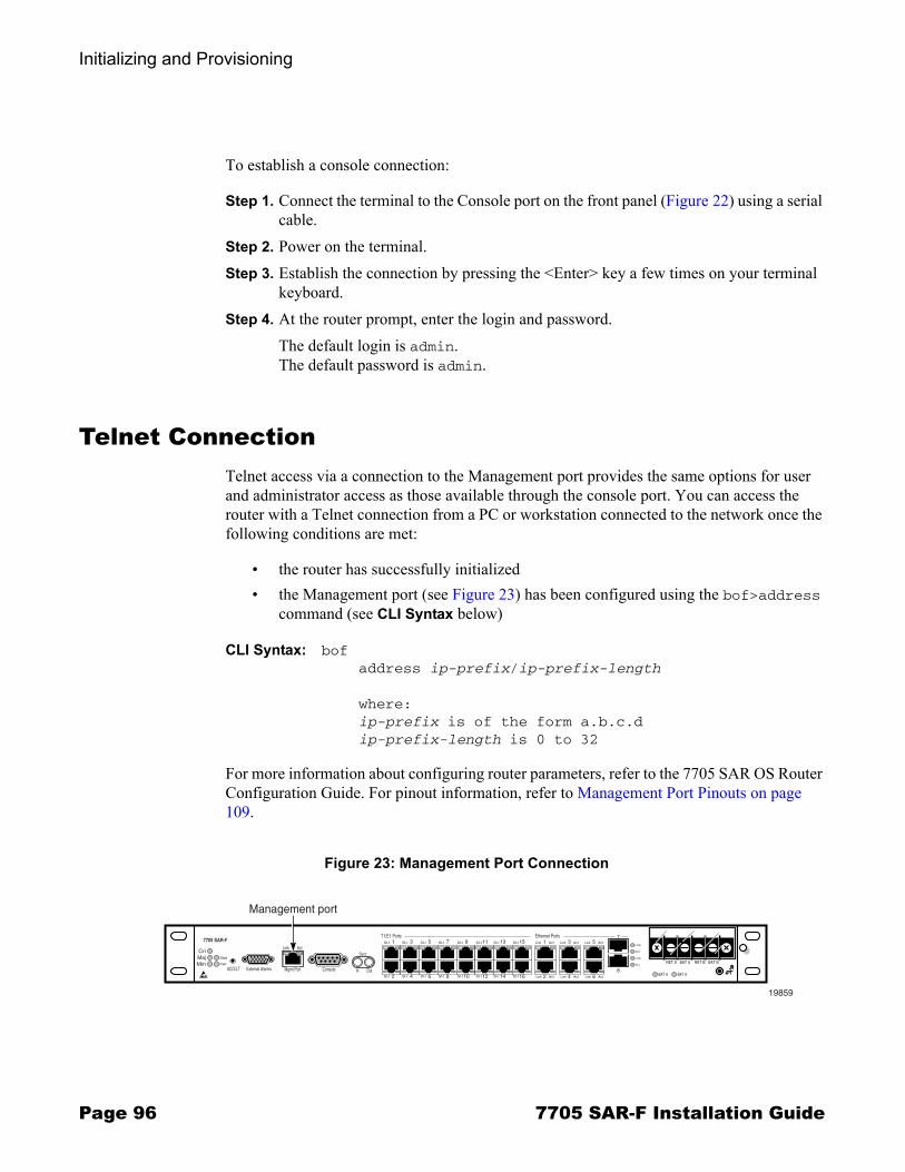
Initializing and Provisioning
Page 96 7705 SAR-F Installation Guide
To establish a console connection:
Step 1. Connect the terminal to the Console port on the front panel (Figure 22) using a serial cable.
Step 2. Power on the terminal.Step 3. Establish the connection by pressing the <Enter> key a few times on your terminal
keyboard.Step 4. At the router prompt, enter the login and password.
The default login is admin.The default password is admin.
Telnet ConnectionTelnet access via a connection to the Management port provides the same options for user and administrator access as those available through the console port. You can access the router with a Telnet connection from a PC or workstation connected to the network once the following conditions are met:
� the router has successfully initialized� the Management port (see Figure 23) has been configured using the bof>address
command (see CLI Syntax below)
CLI Syntax: bof address ip-prefix/ip-prefix-length
where:ip-prefix is of the form a.b.c.dip-prefix-length is 0 to 32
For more information about configuring router parameters, refer to the 7705 SAR OS Router Configuration Guide. For pinout information, refer to Management Port Pinouts on page 109.
Figure 23: Management Port Connection
Cri
7705 SAR-F
MajMin
Stat
Pwr
ACO/LT External Alarms Mgmt Port Console
Link Act
In Out
1T1/E1 Ports
St-t 3St-t 5St-t 7St-t 9St-t 11St-t 13St-t 15St-t 1Link Act
2Link Act
3Link Act
4Link Act
5
8
Link Act
6Link Act2St-t 4St-t 6St-t 8St-t 10St-t 12St-t 14St-t 16St-t
Sync
Ethernet Ports
Link
Act
Link
Act
BAT A BAT A
RET A BAT A RET B BAT B
19859
Management port
7
Initializing and Provisioning
7705 SAR-F Installation Guide Page 97
Running TelnetAfter the Ethernet Management port IP address is configured, the 7705 SAR-F CLI can be accessed with a Telnet connection. To establish a Telnet connection, run a Telnet program and issue the telnet command, followed by the Management port IP address.
The following displays an example of a Telnet login:
C:\>telnet 192.168.1.xx1Login: adminPassword: ########
ALU-1#
The default login is admin.The default password is admin.

Initializing and Provisioning
Page 98 7705 SAR-F Installation Guide
Provisioning the 7705 SAR-FThe 7705 SAR-F does not require provisioning at the card or MDA levels because it is provisioned at the factory with the following permanent configuration:
� card type in slot 1 is csm-1g with iom-1g� mda type in slot 1/1 is a16-chds1v2 (for T1/E1 ports)� mda type in slot 1/2 is a8-ethv3 (for Ethernet ports)
The following CLI display shows the factory-provisioned settings when the show card command is issued.
ALA-12#show card ===============================================================================Card State===============================================================================Slot/ Provisioned Equipped Admin Operational Num Num CommentsId Type Type State State Ports MDA -------------------------------------------------------------------------------1 iom-1g iom-1g up up 2 1/1 a16-chds1v2 a16-chds1v2 up up 16 1/2 a8-ethv3 a8-ethv3 up up 8 A csm-1g csm-1g up up Active ===============================================================================ALA-12#
Example
The CLI display for the example above when the info command is issued looks similar to the following:
ALU-1>config# info. . .----------------------------------------------echo "Card Configuration"#---------------------------------------------
card 1card-type iom-1gmda 1
mda-type a16-chds1v2exitmda 2
mda-type a8-ethv3exit
exit----------------------------------------------ALU-1>config#
Initializing and Provisioning
7705 SAR-F Installation Guide Page 99
T1/E1 and Ethernet Port IdentifiersTable 19 shows the CLI identifiers for the interface ports.
To configure ports, refer to the Card and Port Configuration section of the 7705 SAR OS Interface Configuration Guide.
Table 19: CLI Port Identifiers
Port Type CLI Identifier Variable Definition
T1/E1 1/1/port_id port_id is the port number, from 1 to 16
Ethernet 1/2/port_id port_id is the port number, from 1 to 8

Initializing and Provisioning
Page 100 7705 SAR-F Installation Guide

7705 SAR-F Installation Guide Page 101
Appendix A: 7705 SAR-FConnectors and LEDs
In This ChapterThis chapter provides information on the connectors and LEDs on the front of the 7705 SAR-F. There are no connectors or LEDs on the back of the router:
� 7705 SAR-F Connectors and LEDs on page 102

Appendix A: 7705 SAR-F Connectors and LEDs
Page 102 7705 SAR-F Installation Guide
7705 SAR-F Connectors and LEDsFigure 24 identifies the connectors and LEDs on the front of the router.
Table 20 describes the connectors and LEDs on the 7705 SAR-F.
Figure 24: 7705 SAR-F Connectors and LEDs
Cri
7705 SAR-F
MajMin
Stat
Pwr
ACO/LT External Alarms Mgmt Port Console
Link Act
In Out
1T1/E1 Ports
Stat 3Stat 5Stat 7Stat 9Stat 11Stat 13Stat 15Stat 1Link Act
2Link Act
3Link Act
4Link Act
57
8
Link Act
6Link Act2Stat 4Stat 6Stat 8Stat 10Stat 12Stat 14Stat 16Stat
Sync
Ethernet Ports
Link
Act
Link
Act
BAT A BAT B
+BattA -BattA +BattB -BattB
-48V Batt
19860
1 3
2 4
5 6 7 8 11
12 13 14
9 10
Table 20: 7705 SAR-F Connector and LED Descriptions
Key Label/Part Subcategory
Description
1 Alarm LEDs Critical Red: Indicates that a critical condition exists, such as the failure of two or more fans or a power feedUnlit: Indicates that there are no critical alarm conditions
Major Red: Indicates that a serious condition exists, such as an over-temperature condition or a full compact flash device Unlit: Indicates that there are no major alarm conditions
Minor Amber: Indicates that a minor condition exists, such as the failure of a single fanUnlit: Indicates that there are no minor alarm conditions
2 Pwr LED � Blue: Indicates that power to the router is on and the system is receiving the DC power feed from source A or source B, and the power rails are at their proper levelsUnlit: Indicates that there is no power to the router, or the power is faulty

Appendix A: 7705 SAR-F Connectors and LEDs
7705 SAR-F Installation Guide Page 103
3 Stat (Status) LED
� The system status LED indicates the combined status of the router�s three main functional blocks (the control and switching functional block, the T1/E1 ports functional block, and the Ethernet ports functional block). Blocks that are administratively shut down are not included in the combined status indicated by this LED.Green (solid): Indicates that the system is operationally up, which means that all functional blocks configured to be administratively up are operationally upGreen (blinking): Indicates that one or more functional blocks is initializingAmber: Indicates that one or more functional blocks is operationally down but administratively up, or that hardware is booting upUnlit: Indicates that there is no power getting to the system
4 ACO/LT Push Button
� The Audible Alarm Cutoff/Lamp Test button verifies LED operation and turns off the external alarm control bits.When pressed: The Lamp Test is enabled and the following LED activity occurs:� the status LED on the chassis glows green� all T1/E1 port LEDs glow green� critical and major Alarm LEDs glow red and the minor Alarm LED
glows amberNote: The following LEDS are not affected by the Lamp Test: Management port LEDs, Battery A/B LEDs, and all Ethernet port LEDs.When released: All LEDs except the Alarm LEDs return to their pre-Lamp Test state. The Alarm LEDs turn off and stay unlit until the next new alarm condition.
5 External Alarms
Connector The External Alarms port is a serial port that uses a DB15 female connector. It can receive input signals from four external alarm devices and provide output signals through three sets of contacts. Refer to External Alarms Port on page 110 for pinout assignments.
Table 20: 7705 SAR-F Connector and LED Descriptions (Continued)
Key Label/Part Subcategory
Description
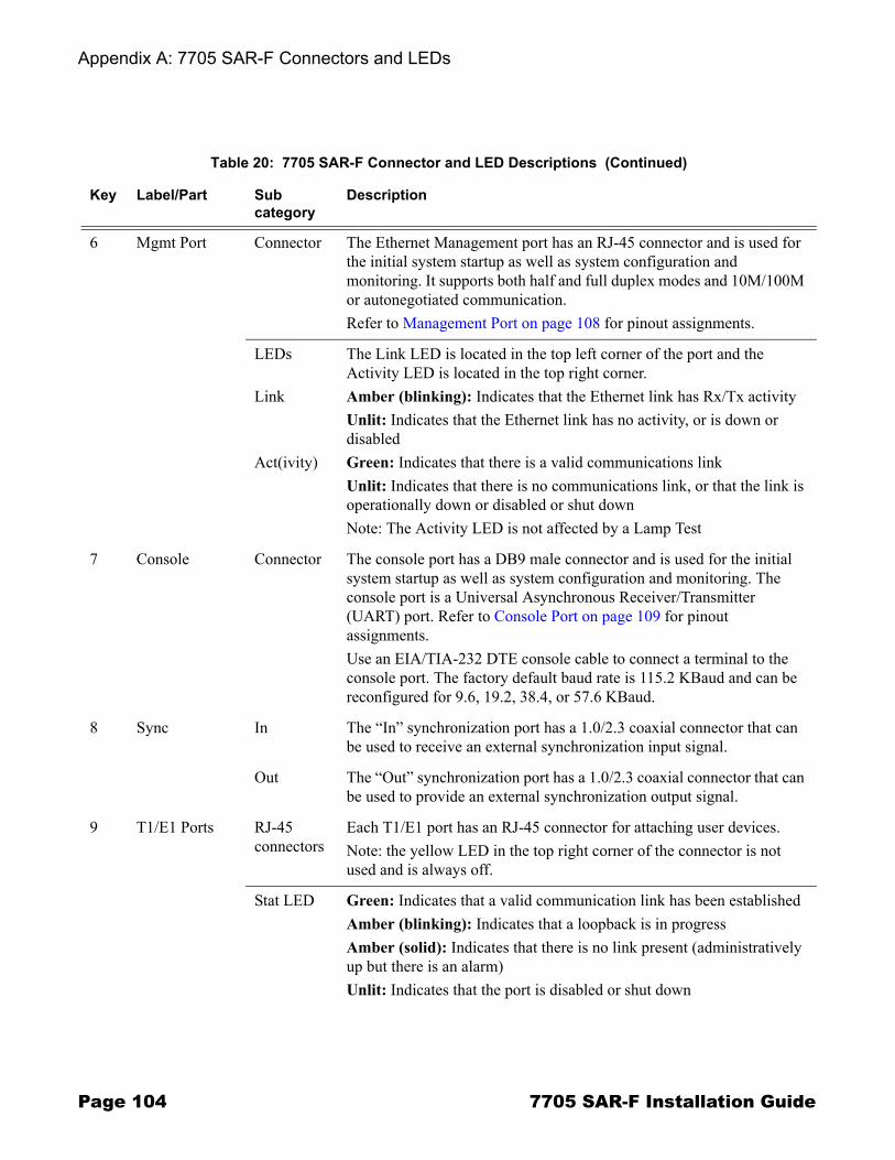
Appendix A: 7705 SAR-F Connectors and LEDs
Page 104 7705 SAR-F Installation Guide
6 Mgmt Port Connector The Ethernet Management port has an RJ-45 connector and is used for the initial system startup as well as system configuration and monitoring. It supports both half and full duplex modes and 10M/100M or autonegotiated communication.Refer to Management Port on page 108 for pinout assignments.
LEDs
Link
Act(ivity)
The Link LED is located in the top left corner of the port and the Activity LED is located in the top right corner.Amber (blinking): Indicates that the Ethernet link has Rx/Tx activityUnlit: Indicates that the Ethernet link has no activity, or is down or disabledGreen: Indicates that there is a valid communications linkUnlit: Indicates that there is no communications link, or that the link is operationally down or disabled or shut downNote: The Activity LED is not affected by a Lamp Test
7 Console Connector The console port has a DB9 male connector and is used for the initial system startup as well as system configuration and monitoring. The console port is a Universal Asynchronous Receiver/Transmitter (UART) port. Refer to Console Port on page 109 for pinout assignments.Use an EIA/TIA-232 DTE console cable to connect a terminal to the console port. The factory default baud rate is 115.2 KBaud and can be reconfigured for 9.6, 19.2, 38.4, or 57.6 KBaud.
8 Sync In The �In� synchronization port has a 1.0/2.3 coaxial connector that can be used to receive an external synchronization input signal.
Out The �Out� synchronization port has a 1.0/2.3 coaxial connector that can be used to provide an external synchronization output signal.
9 T1/E1 Ports RJ-45 connectors
Each T1/E1 port has an RJ-45 connector for attaching user devices.Note: the yellow LED in the top right corner of the connector is not used and is always off.
Stat LED Green: Indicates that a valid communication link has been establishedAmber (blinking): Indicates that a loopback is in progressAmber (solid): Indicates that there is no link present (administratively up but there is an alarm)Unlit: Indicates that the port is disabled or shut down
Table 20: 7705 SAR-F Connector and LED Descriptions (Continued)
Key Label/Part Subcategory
Description
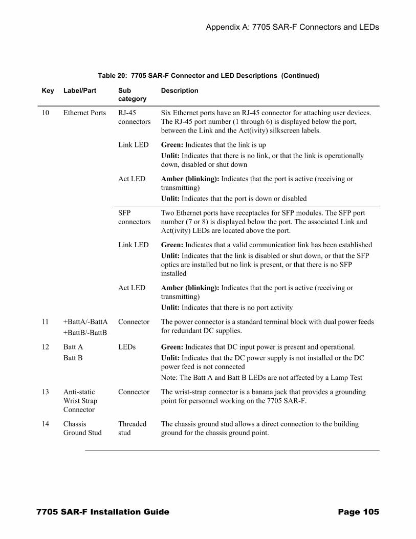
Appendix A: 7705 SAR-F Connectors and LEDs
7705 SAR-F Installation Guide Page 105
10 Ethernet Ports RJ-45 connectors
Six Ethernet ports have an RJ-45 connector for attaching user devices. The RJ-45 port number (1 through 6) is displayed below the port, between the Link and the Act(ivity) silkscreen labels.
Link LED Green: Indicates that the link is upUnlit: Indicates that there is no link, or that the link is operationally down, disabled or shut down
Act LED Amber (blinking): Indicates that the port is active (receiving or transmitting)Unlit: Indicates that the port is down or disabled
SFP connectors
Two Ethernet ports have receptacles for SFP modules. The SFP port number (7 or 8) is displayed below the port. The associated Link and Act(ivity) LEDs are located above the port.
Link LED Green: Indicates that a valid communication link has been establishedUnlit: Indicates that the link is disabled or shut down, or that the SFP optics are installed but no link is present, or that there is no SFP installed
Act LED Amber (blinking): Indicates that the port is active (receiving or transmitting)Unlit: Indicates that there is no port activity
11 +BattA/-BattA+BattB/-BattB
Connector The power connector is a standard terminal block with dual power feeds for redundant DC supplies.
12 Batt ABatt B
LEDs Green: Indicates that DC input power is present and operational.Unlit: Indicates that the DC power supply is not installed or the DC power feed is not connectedNote: The Batt A and Batt B LEDs are not affected by a Lamp Test
13 Anti-static Wrist Strap Connector
Connector The wrist-strap connector is a banana jack that provides a grounding point for personnel working on the 7705 SAR-F.
14 Chassis Ground Stud
Threaded stud
The chassis ground stud allows a direct connection to the building ground for the chassis ground point.
Table 20: 7705 SAR-F Connector and LED Descriptions (Continued)
Key Label/Part Subcategory
Description
Appendix A: 7705 SAR-F Connectors and LEDs
Page 106 7705 SAR-F Installation Guide

7705 SAR-F Installation Guide Page 107
Appendix B: Pinout Assignments
In This ChapterThis chapter provides information about the pinout assignments for the port connectors on the 7705 SAR-F:
� 7705 SAR-F Ports on page 108� Management Port on page 108
→ Management Port Pinouts on page 109� Console Port on page 109
→ Console Port Pinouts on page 110� External Alarms Port on page 110
→ External Alarms Port Pinouts on page 111→ Alarm Examples on page 112
� Ethernet Port on page 112→ Ethernet Port Pinouts on page 113
� T1/E1 Port on page 113→ T1/E1 Port Pinouts on page 114

Appendix B: Pinout Assignments
Page 108 7705 SAR-F Installation Guide
7705 SAR-F PortsFigure 25 identifies the port connectors that are accessible on the 7705 SAR-F.
Management PortThe Management port supports half and full duplex communication via 10/100 or autonegotiated Ethernet. The Management port provides a channel to download software and configuration files and to manage the system. This port has an RJ-45 connector on the front panel. You must provide a CAT5 Ethernet cable to connect to the port.
Figure 26 shows the Management port pin numbers.
Figure 25: 7705 SAR-F Port Connectors
Cri
7705 SAR-F
MajMin
Stat
Pwr
ACO/LT External Alarms Mgmt Port Console
Link Act
In Out
1T1/E1 Ports
Stat 3Stat 5Stat 7Stat 9Stat 11Stat 13Stat 15Stat 1Link Act
2Link Act
3Link Act
4Link Act
57
8
Link Act
6Link Act2Stat 4Stat 6Stat 8Stat 10Stat 12Stat 14Stat 16Stat
Sync
Ethernet Ports
Link
Act
Link
Act
BAT A BAT B
+BattA -BattA +BattB -BattB
-48V Batt
19861
T1/E1 ports Ethernet portsManagementport connector
ExternalAlarms connector
Consoleport connector
Figure 26: Management Port Pin Numbers
Pin 8 Pin 119593

Appendix B: Pinout Assignments
7705 SAR-F Installation Guide Page 109
Management Port Pinouts
Table 21 displays the Management port pin assignments
Console PortThe Console port is a Universal Asynchronous Receiver/Transmitter (UART) port used to configure router and system parameters. It can also be used for monitoring purposes. The Console port is enabled by default and is configured as DTE. The default baud rate is 115 200. This port has a DB9 male connector. Connect the Console port to a terminal using an EIA/TIA-232 serial cable.
Figure 27 shows the Console port pin numbers.
Table 21: Ethernet Management Port Pinouts�RJ-45 Female
Pin Signal Direction Description
1 TX+ Output Differential transmit data � positive
2 TX- Output Differential transmit data � negative
3 RX+ Input Differential receive data � positive
4 NC � Not connected
5 NC � Not connected
6 RX- Input Differential receive data � negative
7 NC � Not connected
8 NC � Not connected
Figure 27: Console Port Pin Numbers
6 9
51
19862

Appendix B: Pinout Assignments
Page 110 7705 SAR-F Installation Guide
Console Port Pinouts
Table 22 displays the Console port pin assignments. The Console port is configured for DTE mode.
External Alarms PortThe External Alarms port provides access to three pairs of alarm output contacts and four alarm inputs. All alarm interfaces are rated for 5 VDC and 100 mA (source or sink). Each alarm input has a fixed severity associated with it�there is one Critical alarm input, two Major alarm inputs, and one Minor alarm input (see Table 23). State transitions on the inputs are debounced for 2 seconds.
The port uses a DB15 female connector. You must provide an appropriate cable configured according to your alarm panel.
You can display the status of the alarm inputs using the show>chassis>environment CLI command.
Table 22: Console Port Pinouts�DB9 Male
Pin Signal Direction Description
1 DCD Input Data carrier detect
2 RXD Input Receive data
3 TXD Output Transmit data
4 DTR Output Data terminal ready
5 GND Signal ground Signal ground
6 DSR Input Data set ready
7 RTS Output Request to send
8 CTS Input Clear to send
9 RI Input Ring indicator
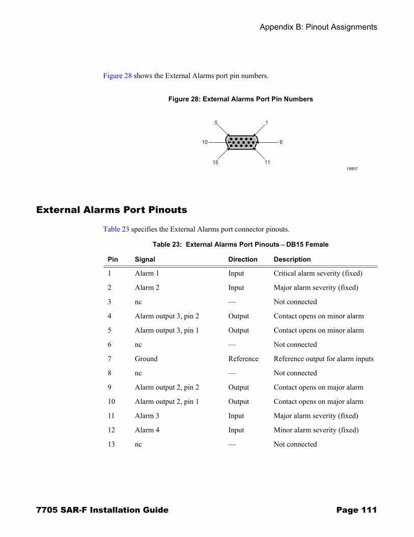
Appendix B: Pinout Assignments
7705 SAR-F Installation Guide Page 111
Figure 28 shows the External Alarms port pin numbers.
External Alarms Port Pinouts
Table 23 specifies the External Alarms port connector pinouts.
Figure 28: External Alarms Port Pin Numbers
10 6
15 11
15
19857
Table 23: External Alarms Port Pinouts�DB15 Female
Pin Signal Direction Description
1 Alarm 1 Input Critical alarm severity (fixed)
2 Alarm 2 Input Major alarm severity (fixed)
3 nc � Not connected
4 Alarm output 3, pin 2 Output Contact opens on minor alarm
5 Alarm output 3, pin 1 Output Contact opens on minor alarm
6 nc � Not connected
7 Ground Reference Reference output for alarm inputs
8 nc � Not connected
9 Alarm output 2, pin 2 Output Contact opens on major alarm
10 Alarm output 2, pin 1 Output Contact opens on major alarm
11 Alarm 3 Input Major alarm severity (fixed)
12 Alarm 4 Input Minor alarm severity (fixed)
13 nc � Not connected

Appendix B: Pinout Assignments
Page 112 7705 SAR-F Installation Guide
Alarm Examples
Table 24 lists critical, major, and minor alarm examples.
Ethernet PortThere are 6 RJ-45 and 2 SFP connectors on the front of the 7705 SAR-F that provide Ethernet access to 8 Ethernet ports.
Use CAT5 (Fast Ethernet) or CAT5E (Gigabit Ethernet) shielded cables to attach customer equipment to the 7705 SAR-F Ethernet ports.
Figure 29 shows the pin numbering.
14 Alarm output 1, pin 2 Output Contact closes on critical alarm
15 Alarm output 1, pin 1 Output Contact closes on critical alarm
Table 23: External Alarms Port Pinouts�DB15 Female (Continued)
Pin Signal Direction Description
Table 24: Alarm Examples
Alarm Severity Examples
Critical � two or more fans have failed� a power feed has failed� a critical external alarm has been detected
Major � an over-temperature condition has been detected� a major external alarm has been detected
Minor � one fan has failed� a minor external alarm has been detected
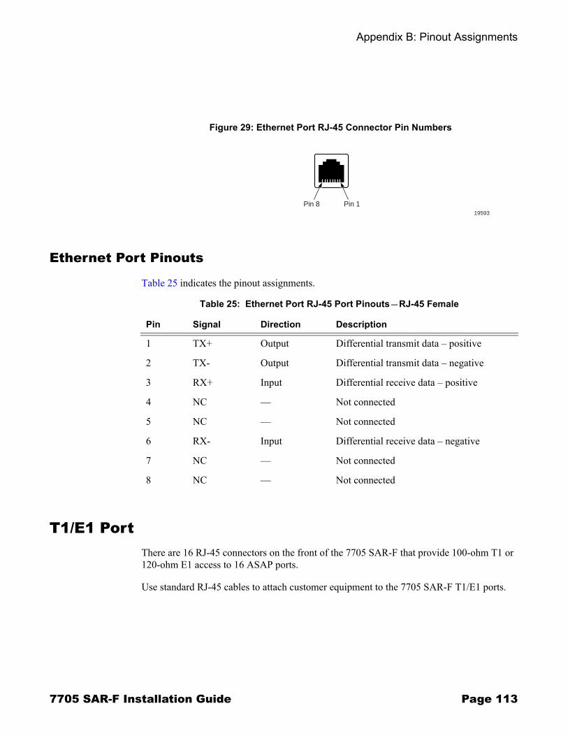
Appendix B: Pinout Assignments
7705 SAR-F Installation Guide Page 113
Ethernet Port Pinouts
Table 25 indicates the pinout assignments.
T1/E1 Port There are 16 RJ-45 connectors on the front of the 7705 SAR-F that provide 100-ohm T1 or 120-ohm E1 access to 16 ASAP ports.
Use standard RJ-45 cables to attach customer equipment to the 7705 SAR-F T1/E1 ports.
Figure 29: Ethernet Port RJ-45 Connector Pin Numbers
Pin 8 Pin 119593
Table 25: Ethernet Port RJ-45 Port Pinouts—RJ-45 Female
Pin Signal Direction Description
1 TX+ Output Differential transmit data – positive
2 TX- Output Differential transmit data – negative
3 RX+ Input Differential receive data – positive
4 NC — Not connected
5 NC — Not connected
6 RX- Input Differential receive data – negative
7 NC — Not connected
8 NC — Not connected
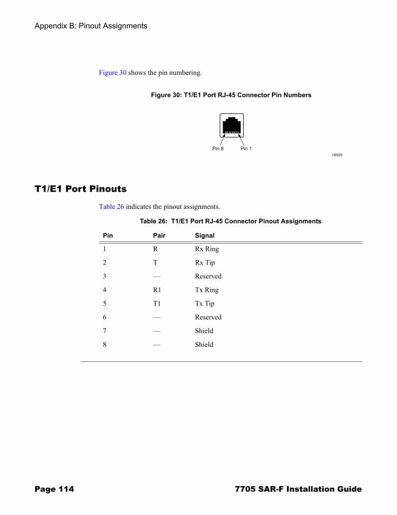
Appendix B: Pinout Assignments
Page 114 7705 SAR-F Installation Guide
Figure 30 shows the pin numbering.
T1/E1 Port Pinouts
Table 26 indicates the pinout assignments.
Figure 30: T1/E1 Port RJ-45 Connector Pin Numbers
Pin 8 Pin 119593
Table 26: T1/E1 Port RJ-45 Connector Pinout Assignments
Pin Pair Signal
1 R Rx Ring
2 T Rx Tip
3 � Reserved
4 R1 Tx Ring
5 T1 Tx Tip
6 � Reserved
7 � Shield
8 � Shield

7705 SAR-F Installation Guide Page 115
Standards and Protocol Support
Standards ComplianceIEEE 802.1p/q VLAN TaggingIEEE 802.3 10BaseTIEEE 802.3u 100BaseTXIEEE 802.3x Flow ControlIEEE 802.3z 1000BaseSX/LX
Protocol Support
LDPRFC 5036 LDP Specification
MPLSRFC 3031 MPLS ArchitectureRFC 3032 MPLS Label Stack EncodingRFC 4379 Detecting Multi-Protocol Label
Switched (MPLS) Data Plane Failures
DIFFERENTIATED SERVICESRFC 2474 Definition of the DS Field in the IPv4
and IPv6 HeadersRFC 2597 Assured Forwarding PHB GroupRFC 2598 An Expedited Forwarding PHBRFC 3140 Per-Hop Behavior Identification Codes
TCP/IPRFC 768 UDPRFC 791 IPRFC 792 ICMPRFC 793 TCP RFC 826 ARPRFC 854 TelnetRFC 1350 The TFTP Protocol (Rev. 2)RFC 1812 Requirements for IPv4 Routers
PPPRFC 1332 PPP IPCP RFC 1661 PPPRFC 1662 PPP in HDLC-like FramingRFC 1989 PPP Link Quality MonitoringRFC 1990 The PPP Multilink Protocol (MP)
ATMRFC 2514 Definitions of Textual Conventions and
OBJECT_IDENTITIES for ATM Management, February 1999
RFC 2515 Definition of Managed Objects for ATM Management, February 1999
RFC 2684 Multiprotocol Encapsulation over ATM Adaptation Layer 5
af-tm-0121.000 Traffic Management Specification Version 4.1, March 1999
ITU-T Recommendation I.610 - B-ISDN Operation and Maintenance Principles and Functions version 11/95
ITU-T Recommendation I.432.1 - B-ISDN user-network interface - Physical layer specification: General characteristics
GR-1248-CORE - Generic Requirements for Operations of ATM Network Elements (NEs). Issue 3 June 1996
GR-1113-CORE - Bellcore, Asynchronous Transfer Mode (ATM) and ATM Adaptation Layer (AAL) Protocols Generic Requirements, Issue 1, July 1994
Standards and Protocol Support
Page 116 7705 SAR-F Installation Guide
PSEUDOWIRESRFC 4385 Pseudowire Emulation Edge-to-Edge
(PWE3) Control Word for Use over an MPLS PSN
RFC 4446 IANA Allocation for PWE3RFC 4447 Pseudowire Setup and Maintenance
Using the Label Distribution Protocol (LDP)RFC 4448 Encapsulation Methods for Transport of
Ethernet over MPLS NetworksRFC 4553 Structure-Agnostic Time Division
Multiplexing (TDM) over Packet (SAToP)RFC 4717 Encapsulation Methods for Transport of
Asynchronous Transfer Mode (ATM) over MPLS Networks
RFC 5086 Structure-Aware Time Division Multiplexed (TDM) Circuit Emulation Service over Packet Switched Network (CESoPSN)
RFC 5085 Pseudowire Virtual Circuit Connectivity Verification (VCCV): A Control Channel for Pseudowires
RADIUSRFC 2865 Remote Authentication Dial In User
ServiceRFC 2866 RADIUS Accounting
SSHdraft-ietf-secsh-architecture.txt SSH Protocol
Architecturedraft-ietf-secsh-userauth.txt SSH Authentication
Protocoldraft-ietf-secsh-transport.txt SSH Transport Layer
Protocoldraft-ietf-secsh-connection.txt SSH Connection
Protocoldraft-ietf-secsh- newmodes.txt SSH Transport Layer
Encryption Modes
TACACS+draft-grant-tacacs-02.txt The TACACS+ Protocol
SYNCHRONIZATIONG.813 Timing characteristics of SDH equipment slave
clocks (SEC)G.8261 Timing and synchronization aspects in packet
networksG.8262 Timing characteristics of synchronous
Ethernet equipment slave clockGR 1244 CORE Clocks for the Synchronized
Network: Common Generic Criteria
NETWORK MANAGEMENTITU-T X.721: Information technology- OSI-Structure
of Management InformationITU-T X.734: Information technology- OSI-Systems
Management: Event Report Management FunctionM.3100/3120 Equipment and Connection ModelsTMF 509/613 Network Connectivity ModelRFC 1157 SNMPv1RFC 1305 Network Time Protocol (Version 3)
Specification, Implementation and AnalysisRFC 1907 SNMPv2-MIBRFC 2011 IP-MIBRFC 2012 TCP-MIBRFC 2013 UDP-MIBRFC 2030 Simple Network Time Protocol (SNTP)
Version 4 for IPv4, IPv6 and OSIRFC 2138 RADIUSRFC 2571 SNMP-FRAMEWORKMIBRFC 2572 SNMP-MPD-MIBRFC 2573 SNMP-TARGET-&-
NOTIFICATION-MIBRFC 2574 SNMP-USER-BASED-SMMIBRFC 2575 SNMP-VIEW-BASED ACM-
MIBRFC 2576 SNMP-COMMUNITY-MIBRFC 2665 EtherLike-MIBRFC 2819 RMON-MIBRFC 2863 IF-MIBRFC 2864 INVERTED-STACK-MIBRFC 3014 NOTIFICATION-LOG MIBRFC 3164 The BSD Syslog ProtocolRFC 3273 HCRMON-MIBRFC 3411 An Architecture for Describing Simple
Network Management Protocol (SNMP) Management Frameworks
RFC 3412 Message Processing and Dispatching for the Simple Network Management Protocol (SNMP)
RFC 3413 Simple Network Management Protocol (SNMP) Applications
RFC 3414 User-based Security Model (USM) for version 3 of the Simple Network Management Protocol (SNMPv3)
RFC 3418 SNMP MIBdraft-ietf-disman-alarm-mib-04.txtdraft-ietf-mpls-ldp-mib-07.txtIANA-IFType-MIB
Standards and Protocol Support
7705 SAR-F Installation Guide Page 117
Proprietary MIBsTIMETRA-ATM-MIB.mibTIMETRA-CAPABILITY-7705-V1.mibTIMETRA-CFLOWD-MIB.mibTIMETRA-CHASSIS-MIB.mibTIMETRA-CLEAR-MIB.mibTIMETRA-FILTER-MIB.mibTIMETRA-GLOBAL-MIB.mibTIMETRA-LDP-MIB.mibTIMETRA-LOG-MIB.mibTIMETRA-MPLS-MIB.mibTIMETRA-OAM-TEST-MIB.mibTIMETRA-PORT-MIB.mibTIMETRA-PPP-MIB.mibTIMETRA-QOS-MIB.mibTIMETRA-ROUTE-POLICY-MIB.mibTIMETRA-SAP-MIB.mibTIMETRA-SDP-MIB.mibTIMETRA-SECURITY-MIB.mibTIMETRA-SERV-MIB.mibTIMETRA-SYSTEM-MIB.mibTIMETRA-TC-MIB.mib

Standards and Protocol Support
Page 118 7705 SAR-F Installation Guide
7705 SAR-F Installation Guide Page 119
Index
Numerics7705 SAR-F
comparison to 7705 SAR-8 44components 40connectors and LEDs 102control and switching features 41fan operation 43installation process 46ports
console 41, 109Ethernet 42, 112external alarms 41, 110management 41, 108synchronization 41T1/E1 42, 113
power supply inputs 42storage specifications 57
Aalarm examples 112
Ccable connections
Ethernet and copper 84chassis
clearance requirements 53DC power
connections 71warnings 70wiring 71
ground wiring 65installation
cabling 56choosing a location 52DC power requirements 56grounding 54placement 54
location requirements 52making the ground connection 65rack-mounting 62specifications 50
storage specifications 57unpacking 60
compact flashdirectory structure 94
connectionsconsole 95copper cable 84external alarm 88external synchronization 87fiber cable 85shield ground 86Telnet 96
connector descriptions7705 SAR-F 102
console port pin assignments 110
DDC-input power connections 71
EEMC compliance
cables 86environmental specifications 50Ethernet ports
cable connectionscopper 84fiber cables 85
pin assignments 113external alarm connections 88external alarms port
pin assignments 111external synchronization connections
source input 87source output 87
Ffan operation
monitoring temperature 43fans
airflow 57safety 57

Page 120 7705 SAR-F Installation Guide
Index
fiber cableshandling 78lock and release mechanisms 78
Ggrounding
ground connection 65
Iinitializing the system
procedure 92troubleshooting 93
installation7705 SAR-F overview 46chassis location requirements 52
installing7705 SAR-F chassis 62components
SFPs 77
LLED descriptions
7705 SAR-F 102
Mmanagement port
pin assignments 109
OOS software
directory structure 94
Pport pin assignments
console port 110Ethernet port 113external alarms port 111management port 109T1/E1 port 114
ports 108power
input connections 71wiring DC inputs 71
Rrouter
powering up 92troubleshooting initial startup 93
router managementconsole connection
console port 95default settings 95establishing 95
Telnet connectionaccess conditions 96login 97management port 96
Ssafety
cabling 56during site preparation 54fans 57grounding 54placement 54power 56
SFPsinstalling 77, 80removing 80types supported 79
shield ground connections 86site preparation
compliance 57Standards & Protocols
proprietary MIBS 117protocols 115standards compliance 115
storage specifications 57system software
directory structure 94system specifications 50
chassis specifications 50environmental specifications 50power consumption 51

7705 SAR-F Installation Guide Page 121
Index
TT1/E1 ports
cable connectionscopper 84
pin assignments 114temperature
monitoring 43troubleshooting
system startup 93
Uunpacking the chassis 60

Page 122 7705 SAR-F Installation Guide
Index

Customer documentation and product support
Technical support
Customer documentation
Product manuals and documentation updates are available through the Alcatel-Lucent SupportDocumentation and Software Download service at alcatel-lucent.com. If you are a new userand require access to this service, please contact your Alcatel-Lucent sales representative.
Customer documentation feedback
http://www.alcatel-lucent.com/support
http://www.alcatel-lucent.com/osds

© 2008 Alcatel-Lucent. All rights reserved.3HE 04304 AAAA TQZZA Edition 01


