
Factory of Rolling Bearings and Cardan Shafts - FKL
Industrijska zona bb21235 TEMERIN
SERBIA
Phone.: +381 21 6841 100Fax: +381 21 842 650
E-mail: [email protected]
http://www.fkl-serbia.com
Agricultural bearings and cardan shafts
Copyright © 2013 FKL. All rights reserved. These contents are the copyright of the publisher and may not be reproduced, in total or partially, without express consent of the publisher. Every precautions were taken to ensure the accuracy of the information in this publication but no liability can be accepted for any errors or omissions.Prepared in Factory of rolling bearings and cardan shafts Temerin, Serbia
Editor in Chief: Milivoje Mijušković, B. Sc. Mechanical EnginnerCopy Editor: Geza Barna, B. Sc. Mechanical Enginner; Biljana Bukvić, Master in Mechanical Engineer; Gordana Pavlović, Mechanical EngineerPhotos, Layout and Prepress: Monja Madić, Master in Graphic Engineer and Design

ww
w.f
kl-s
erbi
a.co
m
ww
w.f
kl-s
erbi
a.co
m
32
1.1 INTRODUCTION
This catalog is prepared in order to present all important information about the products and their characteristics in “easy to find“ manner. Whether looking for the particular product, or solution to the specific problem. This catalog represents the choice of most frequent FKL ball bearings and cardan shafts. This is selection of products that have steady demand and are used in a wide range of applications. Our users are familiar with benefits of FKL products. This catalog is primarily designed for end users, so the technical data are reduced to a minimum.
The catalog of rolling bearings and cardan shafts includes designations and principal dimensions for all types of bearings and cardan shafts that are used to a greater or lesser extent. The catalog also includes an overview of basic production program with comparative designation. The basic designation defines the type of the bearing, size series and the diameter of the bore by the defined order. Suffixes that appear in this catalog and ones that are frequently used are listed and explained in a specified table. Designations of housings follow similar designation system and can be found in the catalog as well. Other European and worldwide producers that are not included in this catalog have similar comparative designations. Additional designations are also specified as well as other necessary explanations.
Technology utilized for the production of the bearings and cardan shafts provides significant advantages to customers due to minimal maintenance costs. Each bearing should have longer life span and should operate without any problems during the exploitation. However, it should be noted that certain external factors affect the quality of bearings as well. They should not be exposed to excessive heat and must be protected from ingress of foreign matter. Also, bearings must be properly lubricated.
This catalog presents bearings designed for agricultural equipment like combine harvesters, harrows, mowers, sugar beet harvesters... Development of the agricultural industry is followed by development of the cultivation and harvesting machinery. Each stage of cultivation requires special machinery that is either self-propelled or tractor driven, depending on operating conditions. Earlier generations of the machines were equipped with bearings that worked at lower speeds and supported lighter loads.
Modern ball bearings stand up to growing demands of operation in difficult conditions with increased productivity. Further development trends set demands for longer exploitation life under harsh conditions and more cost-effective design for agricultural machinery. Y-bearings provide cost-effective solutions and are extensively applied in agricultural machinery production. These bearings are quick and easy to mount. Wide inner ring can be mounted on the shaft by the eccentric ring, screws or adapter sleeves. Seals are specially designed and fitted to the outer ring. The advantages of these bearings have led to their rapid adoption by manufacturers of agricultural machinery.Each FKL bearing is produced in accordance with strict premium quality standards.
1. Product information
1. Product information
1.1 Introduction ............................................................................................................... 3 1.2 Sealing ....................................................................................................................... 4 1.3 Lubrication ................................................................................................................. 6 1.4 Materials .................................................................................................................... 8 2. Installation
2.1 Shaft tolerance and speed limit number .................................................................. 9 2.2 Tightening ................................................................................................................. 9 2.3 Protective caps........................................................................................................ 10
3. Y program 3.1 Designation system and comparative designation for Y-bearings and bearing units .... 12 3.2 Y bearings data ........................................................................................................ 17 3.3 Bearing units 3.3.1 S............................................................................................................... 30 3.3.2 V .............................................................................................................. 32 3.3.3 U .............................................................................................................. 34 3.3.4 F............................................................................................................... 36 3.3.5 N .............................................................................................................. 38 3.3.6 G .............................................................................................................. 40 3.3.7 T, TJ .......................................................................................................... 42 3.3.8 C .............................................................................................................. 46 3.3.9 D .............................................................................................................. 48 3.3.10 P ............................................................................................................ 50 3.3.11 R ............................................................................................................ 52 3.4 Disc harrow bearings first generation ....................................................................... 54 3.5 Disc harrow bearings second generation ................................................................. 64 3.6 Disc harrow bearings third generation ..................................................................... 67 3.7 Bearing units type 2TB.............................................................................................. 68 3.8 Bearing units type 2TC .............................................................................................. 70 3.9 Special bearings ....................................................................................................... 71 4. Program of cardan shafts 4.1 Cardan shafts ........................................................................................................ 74 4.2 Table of drive shaft yokes ...................................................................................... 75 4.3 Overload and overrunning clutches ...................................................................... 77
5. Other information ............................................................................................................... 79
CONTENTS

ww
w.f
kl-s
erbi
a.co
m
ww
w.f
kl-s
erbi
a.co
m
54
It is an economic and space-saving solution. Bearings can have shields or seals at one or both sides, those which are sealed at both sides are supplied with grease and are generally maintenance-free. Sealed bearings are generally in application where a sufficiently effective external seal cannot be provided, due to inadequate space or cost effectiveness. Bearings fitted with shields are applied where the possibility of foreign matter ingression is low and no danger of water, steam etc. coming in contact with the bearing, or where the freedom of friction of these non-contact seals is important because of the speed or operating temperature of the bearing. Bearing fitted with contact seals are preferred in application where contamination is moderate and where dampness, water, steam etc. may occur, or where a long exploitation life without maintenance is required.
1.2.1 Bearing sealing
Fig. 3 Sealing 2RSThe older type of the single seal. Prevents penetration of soil, dust and water and since exposed to the impact of abrasive particles is expendable more than some new types of seals. Due to extended friction, the permitted speeds are lower. It was gradually replaced with the improved versions of (2S). Because of the traditional reasons Y bearings with this kind of seal do not have the additional sealing mark. It is used with the Y-bearings and deep groove ball bearings.
Fig. 2 Sealing 2SSingle seal with the labyrinth between the sheet part and the rubber lip which conducts the contact sealing. The friction and speeds are the same as with 2RS but provides much better protection against the rough impurity particles. This is very good sealing system: the sheet part protects the seal from the soil, dust and rough particles. At the same time makes the labyrinth with the rubber part. The rubber part provides contact sealing which prevents penetration of finer impurities, water, moisture, steam etc. Suitable for neutral conditions because of the presence of the foreign materials. It is used with the Y bearing (standard) and deep groove ball bearings.
Fig. 5 Sealing 2TBy construction is the same as 2S, except rubber lip is tripled. Therefore, it seals better but has even larger friction. The permitted speeds are much lower, up to 500. It emerges out of external ring width and is applied only with special bearings for the agricultural machines (practically standard sealing for the disc harrow bearings) and to the less extent, Y - bearing program (delivery is made according to special request).
Fig. 4 Sealing 2FDual sealing; protection cover placed on the inner ring protects against rough impurity particles and makes the labyrinth with the sheet part of the seal; then the sealing 2S type, with the labyrinth between the sheet part and the rubber lip that conducts the contact sealing. The friction and speeds are the same as with 2S but has much better protection against rough impurity particles. It is very good sealing system: the sheet part protects the seal from the soil, dust and rough particles. At the same time makes the labyrinth with the rubber part. The rubber part provides the contact sealing that prevents the penetration of the finer impurities, water, moisture, steam etc. Suitable for heavier conditions due to better protection against foreign matters. It is used with the Y bearings (standard).
Fig. 6 Sealing 2BDual contact sealing, design similar to 2F but protection cover has rubber lip resting on the sheet part of the inner contact seal providing an additional protection against the penetration of the finer impurities, water, moisture, steam etc. The friction is larger than with 2F and permitted speeds are about 50% lower. It is used with the Y bearings (delivery is made according to special request).
1.2 Sealing
Fig. 7 Sealing 2TBDual sealing, combination 2T and stronger protection steel. Friction and speeds are the same as 2T, but considerably better protection against rough dirt. This type of sealing is applied in agricultural machinery. Protection steel protects from soil, dust, rough dirt and mechanical impact on the seal. Triple-lips seal performs contact sealing that prevents penetration of finer dirt, water, damp etc. Suitable for difficult working conditions with aggressive presence of foreign matter. Used with Y bearing units 2TB.
Fig. 1 Sealing 2ZNon-contact sealing with Steel sheet shield of simple and cheap make. Grease prevents penetration of rough impurities. Allows the highest speeds. It is used with the deep groove ball bearings.

ww
w.f
kl-s
erbi
a.co
m
ww
w.f
kl-s
erbi
a.co
m
76
FKL bearings and bearing units with integral seals and shields at both sides are sufficiently greased for the lifetime and should not be lubricated, except when used in very harsh working conditions. Standard greases used by FKL in those products have optimal temperature range and other characteristics suitable for the intended application areas. Filling grades correspond to the bearing size. Relubrication is possible with Y bearings and bearing units supplied with lubricators and corresponding grease channels. FKL sealed bearings are filled with lithium-grease consistency 2 and cinematic viscosity of basic, mineral oil around 90 mm2/s; temperature range of application ranges from -30 up to +120°C.
1.3.1 Grease lubricationAbout 90% of all bearing arrangements are lubricated with grease. Grease has certain advantage comparing to oil because it is easier to retain in the bearing arrangement, particularly with inclined or vertical shafts, and also improves sealing the arrangement against contaminants, moisture or water. However, the shortcoming is lower speeds comparing to oil lubrication. With higher speed bearings, the excess lubricant would cause rapid rise of operating temperature. As a general rule, therefore only the bearing should be completely filled, whilst the free space in the housing should be greased between 30 and 50%. Where the bearings are to operate at very low speed and must be well protected against corrosion, it is advisable to completely fill the housing with grease.
1.3.1.1 Lubricating greasesLubricating greases consist of mineral or synthetic oil combined with a thickener. The thickeners are usually metallic soaps. Additives can also be included to enhance certain characteristics of the grease. The consistency of the grease depends largely on the type and concentration of used thickener. When selecting grease, the viscosity of the base oil, the consistency, operating temperature range and the load carrying ability are the most important factors to be considered.
Base oil viscosityThe base oil viscosity of the greases normally used for rolling bearings lies between 15 and 500 mm2/s at 40°C. Greases based on oils having higher viscosities than 1000 mm2/s at 40°C bleed oil so slowly that the bearing will not be adequately lubricated. Therefore, if a very high viscosity is required because of low speeds, oil lubrication will generally be found more reliable. The base oil viscosity also governs the maximum permissible speed at which given grease can be used for bearing lubrication. For applications operating at very high speeds, the most suitable greases are those incorporating diester oils of low viscosity. The permissible operating speed for grease is also influenced by the shear strength of the grease, which is determined by the thickener.A is speed factor A=n x dm is often quoted by grease manufacturers to indicate the speed capability; n is the rotational speed and dm is the bearing mean diameter - dm=0, 5(d+D).
ConsistencyGreases are divided into various consistency classes (DIN 51 818), according to the National Lubricating Grease Institute (NLGI) Scale. The consistency of greases used for bearing lubrication should not change unduly according to temperature within the operating temperature range or due to mechanical operation. Greases that soften at elevated temperatures may leak from the bearing arrangement. Those that stiffen at low temperatures may restrict rotation of the bearing. Metallic soap thickened greases of consistency 1, 2 or 3 are those normally used for rolling bearings. The consistency 3 greases are primarily recommended for bearing arrangements with vertical shafts.
Protection against corrosionThe grease rust inhibiting characteristics are mainly determined by the rust inhibitors which are added to the grease and its thickener. Grease should provide protection to the bearing against corrosion and should not be washed out of the bearing in case of water penetration. These two features are possessed by lithium and calcium based greases containing lead base additives. However, because of environmental and health reasons such additives are being replaced by other combinations of additives which do not always provide lubricant with such good features.
Load carrying abilityFor heavily loaded bearings, e.g. rolling mill bearings, it has been accustomed to recommend the use of greases containing EP additives, since those additives increase the load carrying ability of the lubricant film. Originally, most EP additives were lead-based compounds and there were arguments suggesting benefits in bearing life extension where lubrication was otherwise poor without elastic-hydrodynamic lubricant film.
MiscibilitySome greases are incompatible and if mixed together the consistency can change dramatically as well as allowed operating temperature. Greases having the same thickener and similar base oils can generally be mixed without any consequences.
Lithium and calcium base greases are generally miscible with each other but not with sodium base greases. However, mixtures of compatible greases may have a consistency which is less than either of the component greases, although the lubricating characteristics are not necessarily impaired. In bearing arrangements where a low consistency might lead to grease leakage from the arrangement, the next relubrication should involve complete replacement of the grease rather than replenishment.
1.3.1.2 RelubricationRolling bearings have to be relubricated if the operating life of the used grease is shorter than the expected life span of the bearing. Relubrication should be performed while lubrication of the bearing is still satisfactory. The time at which relubrication should be undertaken depends on many factors which are related in a complex manner. Those include bearing type and size, speed, operating temperature, grease type, space around the bearing and the bearing environment. The following information is based on long-term tests in various applications but does not apply to applications where water and /or solid contaminants can penetrate the bearing arrangement. In such cases it is recommended that the grease is frequently renewed in order to remove contaminants from the bearing.
Relubrication intervalsRelubrication intervals t1, for normal operating conditions can be calculated as a function of bearing speed n and bore diameter d of a certain bearing type from Diagram 1. The diagram is valid for bearings on horizontal shafts in stationary machines under normal loads. It applies to good quality lithium base greases at a temperature not exceeding 70°C. To calculate accelerated ageing of grease due to increased temperature it is recommended to split intervals obtained from the diagram by half for every 15°C increase in bearing temperature above 70°C. The intervals may be extended at temperatures lower than 70°C but as operating temperatures decrease the grease will bleed oil less readily and with lower temperatures the extension of intervals by more than two times is not recommended. For bearings on vertical shafts the intervals obtained from the diagram (t1,) should be halved. For large roller bearings having d of 300 mm and above, the high specific loads in the bearing mean that adequate lubrication will be obtained only if the bearing is more frequently relubricated than indicated by the diagram, and the lines are therefore broken. It is recommended in such cases when continuous lubrication is practiced for technical and economic reasons. The grease quantity to be supplied can be obtained from the equation below:
Gk=(0,3...0,5)D B 10-4
where Gk grease quantity to be continuously supplied, g/hD bearing outside diameter, mmB total bearing width (for thrust bearings use total height H), mm
Relubrication proceduresOne of the two procedures described below should be used, depending on the relubrication interval t1 obtained:
1. If the relubrication interval is shorter than 6 months, then it is recommended that the grease filling the bearing arrangement should be replenished (topped up) at intervals corresponding to 0,5 t1, the complete grease fill should be replaced after three replenishments, at the latest. Suitable quantities for replenishment can be obtained from
Gp=0,005 D B
whereGp grease quantity to be added when replenishing, gD bearing outside diameter, mmB total bearing width (for thrust bearings use total height H), mm
1.3 Lubrication

ww
w.f
kl-s
erbi
a.co
m
ww
w.f
kl-s
erbi
a.co
m
98
2.1 Shaft tolerance and speed limit number Speed ratings Speed is limited by two factors:1. By the shaft tolerance on which the bearing is mounted; as tighter fitting is more resistant to shock loads and vibrations and vice versa, fitting with greater clearance is sensitive to those influences and lower speed can be allowed. Recommendations for speed rating, depending on the shaft tolerance, are shown in the Table 1.2. By the type of sealing because the friction between the sealing and bearing ring increases the operating temperature in proportion to the speed. For normal sealing 2S and 2F data are shown in the following table. For sealing 2B allowed speed is 55 - 60% from that given in the table.For bearings with three-lip sealing 2T, 2TB and 2TC (bearings for agricultural machinery) allowed speed is max. 500 min-1 unless it is lower according to the Table 1.
Bearing type → UE, LE, UY, LY, LCShaft tolerances LK 1726..., LSShaft
diameter d m7, k7 h6 h7 h8 h9 h1112 12000 9500 6000 4300 1500 950 - 1400015 12000 9500 6000 4300 1500 950 - 1300017 12000 9500 6000 4300 1500 950 - 1200020 10000 8500 5300 3800 1300 850 7000 1000025 9000 7000 4500 3200 1000 700 6300 1000030 7500 6300 4000 2800 900 630 5300 750035 6300 5300 3400 2200 750 530 4800 630040 5600 4800 3000 1900 670 480 4300 560045 5300 4300 2600 1700 600 430 4000 500050 4800 4000 2400 1600 560 400 3600 480055 4300 3600 2000 1400 500 360 3400 -60 4000 3400 1900 1300 480 340 3000 -65 3600 3000 1700 1100 430 300 2600 -70 3300 2800 1600 1000 400 280 2400 -80 2800 2400 1400 900 360 240 2200 -90 2400 2000 1200 800 320 200 - -
100 2200 1900 1100 750 300 190 - -120 1900 1700 900 600 250 160 - -
Table 1. Speed ratings for Y bearings
Axial load carrying capacity
Tightening torques for grub screws locking the bearings on the shaft, as well as axial load capacity of shaft-bearing connections are shown in the Table 2.
Shaft diameter (mm) up to 20 25 30 35 40 45 50 55 60 65 70 75 80 85 90 100 120Tightening torque (Nm) Hook spanner (mm)Axial load (kN)
432
533
634
1245
1246
1248
2359
235
10
235
12
235
14
235
14
235
15
236
16
236
16
236
16
236
16
236
16
Table 2. Axial load carrying capacity
1.4 Materials
2. When lubrication intervals are longer than 6 months it is recommended that all used grease should be removed from the bearing arrangement and replaced by fresh grease.All these are rough guidelines if there are no specific recommendations by the manufacturer or maintenance service. To facilitate the supply of grease using a grease gun, a grease nipple should be provided on the housing. It is also necessary to provide an exit hole for the grease so that excessive amounts would not build up in the bearing surrounding space. Otherwise it might cause permanent increase in the bearing temperature. However, as soon as the appropriate temperature is reached after relubrication, the exit hole should be plugged or clogged so the oil bled by the grease could remain at the bearing position. The danger of excess grease collection in the space surrounding the bearing, causing temperature peaking with its detrimental effect on the grease as well as the bearing, is most emphasized when bearing operates at high speeds. In such cases it is advisable to use a grease discharge valve rather than an exit hole. A grease discharge valve consists basically of a disc which rotates with the shaft and forms a narrow gap with the housing end cover. Excess and used grease is thrown out by the disc into an annular cavity and leaves the housing through an opening on the bottom side of the end cover.To ensure the fresh grease actually reaches the bearing and replaces the old grease, lubrication duct in the housing should either feed the grease adjacent to the outer ringside face or, into the bearing tracks. In general, one should pay attention to grease density and that it does not remain within the bearing.
1.3.2 Bearing storageWhen bearings are stored in their original packaging, they are corrosion protected for several years. Warehouse humidity should not exceed 60%. In case of sealed bearings, if kept in stock for a long period of time, grease may solidify so after the bearing is mounted, its friction moment is higher in comparison to new bearings. Therefore, this should be taken into consideration.
The rings of the bearings and rolling elements are made of special steel (100Cr6 by ISO 683-17:1999) manufactured by the method of vacuum degasification. They are exposed to heat treatment to retain dimensions stability to 150°C.The cages for standard operating temperatures (-20 to +120°C) are made of plastic (ULTRAMID A4H, POLYAMIDE 66). The positive effects of POLYAMIDE, elasticity and small weight, are evident on the high impact bearing load and negative acceleration. The cages of POYIAMIDE possess very good sliding characteristics and steady operation.The pressed cages are made out of steel sheet.Some massive cages are made of brass.The seals are rubber made (PERBUNAN, BUNA M) and vulcanized onto the sheet guard plate. They can operate in temperature range from - 20 to +120°C.Flingers are made of steel sheet.Housings of the Y-bearings are made of cast iron, hardness 200 HB or cold-rolled steel sheet.Grease for common operation temperatures (between -20 and +120°C) is lithium base grease, consistency of the grease 2, viscosity at 40°C is 90 mm2/s.
2.2. Tightening
2. Installation
Diagram 1. Relubrication interval
Scale a: deep groove ball bearingsScale b: cylindrical roller bearings, needle bearingsScale c: spherical, taper roller bearings, thrust ball bearings roller bearings – full complement (0,2 t1), cross-roller bearings with cage (0,3t1) thrust roller, needle, spherical bearings (0,5t1,)

ww
w.f
kl-s
erbi
a.co
m
ww
w.f
kl-s
erbi
a.co
m
1110
For cast iron housing bearing units FKL makes plastic protection caps against external influences. They are set at the end of shaft.The material is highly resistant polypropylene with 20% glass fibers.
Bearing unitsProtective caps
Dimensions (mm) Groove dimensions (mm)Designation A d1 d2 d3 h b min D7 D8
ECF 204 20,5 49 50,5 43 2,3 2,5 46 49ECF 205 20,5 54 55,5 48 2,3 2,5 50,4 54ECF 206 22,5 65 66,5 58 2,3 2,5 60 65ECF 207 24,5 75 76,5 68 2,3 2,5 70,2 75ECF 208 26 83 84,5 75 2,3 2,5 78 83ECF 209 26,5 88 89,5 80 2,3 2,5 83 88ECF 210 46 94 96 86 1,5 2,5 88 94ECF 211 35 104 105,5 88 2,3 2,5 99 105ECF 212 37 116 117,5 98 2,8 3 109 116
Table 3.Protective caps
Possibility of ordering:1. Only cap (example size 207): ECF 2072. Only housing ( example S 207 with cuts for caps): S 207 E3. Housing S 207 + cap (without bearing): S 207 + ECF4. Bearing LY 207 2F + housing S 207 E (without cap): LYS 207 2F.E5. Set (bearing + housing + cap): LYS 207 2F + ECF
Suffix E at the end of designation for bearing units means that there is groove for cap and vice versa, if bearing unit without suffix E is ordered groove for cap does not exists and the cap can't be set. Bearing units with the end designation +ECF will be supplied with a cap.
Fig.8. Protective caps FKL ECF 210
2.3. Protective caps
Fig.9. Technical drawing FKL ECF 210

ww
w.f
kl-s
erbi
a.co
m
ww
w.f
kl-s
erbi
a.co
m
1312
3. Y PROGRAM
Y-bearing units represent the main FKL production program, which is characterized by:
- Compatibility with ISO standards
- Market/customer focused range
- Premium quality products and reliable delivery service
How to use this publication
1. Select the bearing type2. Select the housing design3. Check that the selected unit is in the „Y-units“4. Determine the unit designation
3.1 Designation system and comparative designation for Y - bearings and bearing unitsS
SY(J) SG ASE P P
V SYFJ - - PA UP
U SYF - SHE - -
FFY
(J)FG
56CF
/CJ
F F
N FYT -
CFT/
CJT
FL FL
G FYC
FG16 FE FC FC
T TU - - T T
C PF FB MSB PF PF
D PFD -
MST
RPF
T -
P PFT
FBB
MST
PFL
PFL
R P SB B/T
PP PP
UES
SY(J)
.RM
-PA
SEY
UBP AS
P
UEV
SYFJ
.RM
- -U
BPA
ASU
P
UEU
SYF.R
M-
PSHE
Y- -
UEF
FY(J)
.RM
-PC
JYU
BF ASF
UEN
FYT.
RM -PC
JTY
UBF
LAS
FL
UEG
FYC.
RM - -U
BFC
ASFC
UET
TU.R
M- -
UBT AS
T
UEC
PF.R
M - RAY
UBP
FAS
PF
UED
PFD.
RM -PA
RTRY
- -
UEP
PFT.
RM -RA
TYU
BPFL
ASPF
L
UER
P.RM - PB
YU
BPP
ASPP
LES
SY(J)
.TF
SG56
2RA
SEY
UCP
UCP
LEV
SYFJ
.TF
- -U
CPA
UCU
P
LEU
SYF.T
F-
RSHE
Y- -
LEF
FY (J
).TF
FG56
2RC
JYU
CFU
CF
LEN
FYT.T
F-
RCJT
YU
CFL
UCF
L
LEG
FYC.
TF - -U
CFC
UCF
C
LET
TU.T
F- -
UCT
UCT
LEC
PF.T
FFB
562
RAY - -
LED
PFD.
TF -RR
TRY
- -
LEP
PFT.T
F-
RRTY
ENPF
LAE
LPFL
LER
P.TF - - - -
UYS
SY(J)
.FM
SG16
2PA
SEEN
LP -
UYV
SYFJ
.FM
- - -AE
LUP
UYU
SYF.F
M-
PSHE - -
UYF
FY(J)
.FM
FG16
2PC
J -AE
LF
UYN
FYT.
FM -PC
JT -AE
LFL
UYG
FYC.
FM - - -AE
LFC
UYT
TU.F
M-
PTU
EEN
TAE
LT
UYC
PF.F
MFB
162
RA ENPF
AELP
F
UYD
PFD.
FM -RA
RTR
- -
UYP
PFT.
FM - RAT - -
UYR
(J)
P.FM
SB16
2PB EN
PPAE
LPP
LYS
SY(J)
.WF
SG36
2.B
RASE
EWP
UEL
P
LYV
SYFJ
.WF
- -EW
PAU
ELU
P
LYU
SYF.W
F-
RSHE - -
LYF
FY(J)
.WF
- RCJ
EWF
UEL
F
LYN
FYT.W
F-
RCJT
EWFL
UEL
FL
LYG
FYC.
WF
- RFE
EWFC
UEL
FC
LYT
TU.W
F-
RTU
EEW
TU
ELT
LYC
PF.W
FPB
362.
BRR - -
LYD
PFD.
WF
-RR
TR - -
LYP
PFT.W
F- RRT - -
LYR
P.WF
- - - -U
SSSG
762
.B- - - -
USV - - - - -
USU - - - - -
USF -
FG76
2.B
- - -
USN - - - - -
USG - - - - -
UST - - - - -
USC -
FB76
2.B
- - -
USD - - - - -
USP - - - - -
USR -
SB76
2.B
- - -LS
S - - - - -
LSV- - - - -
LSU - - - - -
LSF - - - -
LSN - - - - -
LSG - - - - -
LST - - - - -
LSC - - - - -
LSD - - - - -
LSP - - - - -
LSR - - - -
UKS - - - - -
UKV - - - - -
UKU - - - - -
UKF
-- - - -
UKN - - - - -
UKG - - - - -
UKT - - - - -
UKC - - - - -
UKD - - - - -
UKP - - - - -
UKR - - - - -
LKS
SY(J)
.KF
- -U
KPU
KP
LKV
SYFJ
.KF
- -U
KPA
UKU
P
LKU
SYF.K
F- - - -
LKF
FY(J)
.KF
- -U
KFU
KF
LKN
LYN
.KF
- -U
KFL
UKF
L
LKG
FYC.
KF - -U
KFC
UKF
C
LKT
TU.K
F- -
UKT
UKT
LKC - - - - -
LKD - - - - -
LKP - - - - -
LKR - - - - -
LEG
END
FKL
SKF
FAG
INA
NSK
NTN
UE
YAT -
GAY.N
PPB
UB AS LE YAR
562
GYE.
KRRB
UC
UC
UY
YET
162
GRAE
.NPP
BEN AE
LLY YE
L36
2.B
GE.K
RRB
EW UEL US
1726
276
2.B
- CS CS LS YFE - - - - UK
3620 - - - - LK YSA - - UK
UK
Designation Y bearing units

ww
w.f
kl-s
erbi
a.co
m
ww
w.f
kl-s
erbi
a.co
m
1514
S V U F N203-204-205-206207-208-209-210211-212-213-214215-216-218-220
204-205-206-207208-209-210
204-205-206-207208-209-210
203-204-205-206207-208-209-210211-212-213-214215-216-218-220
203-204-205-206207-208-209-210211-212
UES12-15-17-20-2530-35-40-45-50
mm bore
UEV20-25-30-35-4045-50
mm bore
UEU20-25-30-35-4045-50
mm bore
UEF12-15-17-20-2530-35-40-45-50
mm bore
UEN12-15-17-20-2530-35-40-45-50
mm bore
LES12-15-17-20-2530-35-40-45-5055-60-65-70-7580-90-100
mm bore
LEV20-25-30-35-4045-50
mm bore
LEU20-25-30-35-4045-50
mm bore
LEF12-15-17-20-2530-35-40-45-5055-60-65-70-7580-90-100
mm bore
LEN12-15-17-20-2530-35-40-45-5055-60
mm bore
UYS12-15-17-20-2530-35-40-45-5055-60
mm bore
UYV20-25-30-35-4045-50
mm bore
UYU20-25-30-35-4045-50
mm bore
UYF12-15-17-20-2530-35-40-45-5055-60
mm bore
UYN12-15-17-20-2530-35-40-45-5055-60
mm bore
LYS12-15-17-20-2530-35-40-45-5055-60-65-70-7580-90-100
mm bore
LYV20-25-30-35-4045-50
mm bore
LYU20-25-30-35-4045-50
mm bore
LYF12-15-17-20-2530-35-40-45-5055-60-65-70-7580-90-100
mm bore
LYN12-15-17-20-2530-35-40-45-5055-60
mm bore
USS17-20-25-30-3540-45-50-55-60
mm bore
USV20-25-30-35-4045-50
mm bore
USU20-25-30-35-4045-50
mm otvora
USF17-20-25-30-3540-45-50-55-60
mm otvora
USN17-20-25-30-3540-45-50-55-60
mm otvora
LSS25-30-35-40-4550-55
mm bore
LSV25-30-35-40-4550
mm bore
LSU25-30-35-40-4550
mm bore
LSF25-30-35-40-4550-55
mm bore
LSN25-30-35-40-4550-55
mm bore
UKS25-30-35-40-4550-55-60-65-7580-85-90
mm bore
UKV25-30-35-40-4550
mm bore
UKU25-30-35-40-4550
mm bore
UKF25-30-35-40-4550-55-60-65-7580-85-90
mm bore
UKN25-30-35-40-4550-55-60
mm bore
LKS25-30-35-40-4550-55-60-65-7580-85-90
mm bore
LKV25-30-35-40-4550
mm bore
LKU25-30-35-40-4550
mm bore
LKF25-30-35-40-4550-55-60-65-7580-85-90
mm bore
LKN25-30-35-40-4550-55-60
mm bore
Y - b e a r i n g s a n d b e a r i n g u n i t s
G T C D P204-205-206-207208-209-210-211212-213
204-205-206-207208-209-210-211212-213-214
203-204-205-206207-208-209-210211-212
203-204-205-206207-208
203-204-205-206207-208
UEG20-25-30-35-4045-50
mm bore
UET20-25-30-35-4045-50
mm bore
UEC12-15-17-20-2530-35-40-45-50
mm bore
UED12-15-17-20-2530-35
mm bore
UEP12-15-17-20-25
30-35-40
mm bore
LEG20-25-30-35-4045-50-55-60-65
mm bore
LET20-25-30-35-4045-50-55-60-6570
mm bore
LEC12-15-17-20-2530-35-40-45-5055-60
mm bore
LED12-15-17-20-2530-35
mm bore
LEP12-15-17-20-2530-35-40
mm bore
UYG20-25-30-35-4045-50-55-60
mm bore
UYT20-25-30-35-4045-50-55-60
mm bore
UYC12-15-17-20-2530-35-40-45-5055-60
mm bore
UYD12-15-17-20-2530-35
mm bore
UYP12-15-17-20-2530-35-40
mm bore
LYG20-25-30-35-4045-50-55-60-65
mm bore
LYT20-25-30-35-4045-50-55-60-6570
mm bore
LYC12-15-17-20-2530-35-40-45-5055-60
mm bore
LYD12-15-17-20-2530-35
mm bore
LYP12-15-17-20-2530-35-40
mm bore
USG20-25-30-35-4045-50-55-60
mm bore
UST20-25-30-35-4045-50-55-60
mm bore
USC17-20-25-30-3540-45-50-55-60
mm bore
USD17-20-25-30-35
mm bore
USP17-20-25-30-3540
mm bore
LSG25-30-35-40-4550-55
mm otvora
LST25-30-35-40-4550-55
mm bore
LSC25-30-35-40-4550-55
mm bore
LSD25-30-35
mm bore
LSP25-30-35-40
mm bore
UKG25-30-35-40-4550-55-60-65
mm bore
UKT25-30-35-40-4550-55-60
mm bore
LKG25-30-35-40-4550-55-60-65
mm bore
LKT25-30-35-40-4550-55-60
mm bore

ww
w.f
kl-s
erbi
a.co
m
ww
w.f
kl-s
erbi
a.co
m
1716
3.2 Y berings dataY BALL BEARINGS WITH STANDARD INNER RING
172...
Shaft Dimensions (mm) Load ratings(kN) Mass Designation
d D B d1 r1,2 C CO Pu kg
15 35 11 21,5 0,6 7,80 3,75 0,16 0,04 1726202-2RS1
17 40 12 24,2 0,6 9,50 4,75 0,20 0,06 1726203-2RS1
20 47 14 28,2 1 12,7 6,55 0,28 0,10 1726204-2RS1
25 52 62
1517
33,636,6
11,1
1422,5
7,8011,6
0,340,49
0,110,20
1726205-2RS11726305-2RS1
30 6272
1619
39,744,6
11,1
19,528,1
11,216
0,480,67
0,180,30
1726206-2RS11726306-2RS1
35 7280
1721
46,149,5
11,5
25,533,2
15,319
0,660,82
0,250,40
1726207-2RS11726307-2RS1
40 8090
1823
5256,1
1,11,5
30,741
1924
0,801,02
0,320,55
1726208-2RS11726308-2RS1
45 85100
1925
56,662,1
1,11,5
32,552,7
20,431,5
0,921,34
0,370,73
1726209-2RS11726309-2RS1
50 90110
2027
62,568,7
1,12
35,161,8
23,238
0,981,60
0,410,95
1726210-2RS11726310-2RS1
55 100 21 69,1 1,5 43,6 29 1,25 0,56 1726211-2RS1
60 110 22 75,5 1,5 52 36 1,40 0,75 1726212-2RS1
65 120 23 82,5 1,5 57 40 1,73 0,94 1726213-2RS1
R203-204-205-206207-208-209
UER12-15-17-20-2530-35-40-45
mm bore
UE
UE 2Size: 03/12-03/15-03-04-05-06-07-08-09-10- Inner ring extended on one side only- Grub screw locking- Seals: Metal-rubber seal- Long life lithium/calcium grease
LER12-15-17-20-2530-35-40-45
mm bore
LE
LE 2Size: 03/12-03/15-03-04-05-06-07-08-09-10-11-1213-14-15-16-17-18-20-24- Inner ring extended on both sides- Grub screw locking- Seals: Metal-rubber seal + metal shield- Long life lithium/calcium grease
UYR12-15-17-20-1530-35-40-45
mm bore
UY
UY 2Size: 03/12-03/15-03-04-05-06-07-08-09-10-11-12- Inner ring extended on one side only- Eccentric locking collar- Seals: Metal-rubber seal- Long life lithium/calcium grease
LYR12-15-17-20-2530-35-40-45
mm bore
LY
LY 2Size: 03/12-03/15-03-04-05-06-07-08-09-10-11-1213-14-15-16-18-20-24- Inner ring extended on both sides- Eccentric locking collar- Seals: Metal-rubber seal + metal shield- Long life lithium/calcium grease
USR17-20-25-30-3540-45
mm bore
US
US 2Size: 03-04-05-06-07-08-09-10-11-12- Inner ring and outer ring same width- Locking by interference on the shaft- Seals: Metal-rubber seal - Long life lithium/calcium grease
LSR25-30-35-40-45
mm bore
LS
LS 2Size: 05-06-07-08-09-10-11- Inner ring extended on both sides- Locking by interference on the shafts- Seals: Metal-rubber seal + metal shield- Long life lithium/calcium grease
UK
UK 2+HSize: 05-06-07-08-09-10-11-12-13-14-15-16-17-18- Bore reduced one size by adapter sleeve- Standard adapter sleeve series H23 (00)- Seals: Metal-rubber seal - Long life lithium/calcium grease- Bearing and adapter sleeve to be ordered separately
LK
LK 2+HSize: 05-06-07-08-09-10-11-12-13-14-15-16-17-18- Bore reduced one size by adapter sleeve- Standard adapter sleeve series H23 (00)- Seals: Metal-rubber seal + metal shield- Long life lithium/calcium grease- Bearing and adapter sleeve to be ordered separately
e a r i n g sB
ww
w.f
kl-s
erbi
a.co
m
ww
w.f
kl-s
erbi
a.co
m
1918
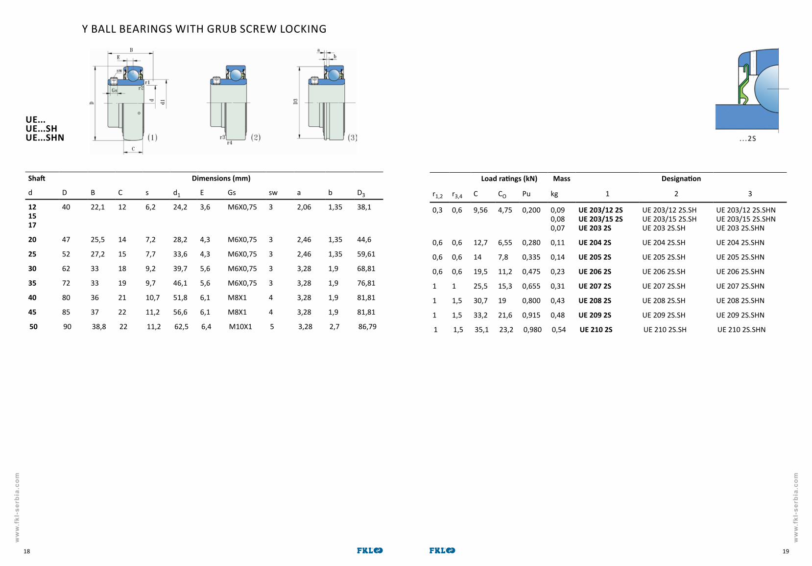
Y BALL BEARINGS WITH GRUB SCREW LOCKING
UE...UE...SHUE...SHN
Shaft Dimensions (mm)
d D B C s d1 E Gs sw a b D3
121517
40 22,1 12 6,2 24,2 3,6 M6X0,75 3 2,06 1,35 38,1
20 47 25,5 14 7,2 28,2 4,3 M6X0,75 3 2,46 1,35 44,6
25 52 27,2 15 7,7 33,6 4,3 M6X0,75 3 2,46 1,35 59,61
30 62 33 18 9,2 39,7 5,6 M6X0,75 3 3,28 1,9 68,81
35 72 33 19 9,7 46,1 5,6 M6X0,75 3 3,28 1,9 76,81
40 80 36 21 10,7 51,8 6,1 M8X1 4 3,28 1,9 81,81
45 85 37 22 11,2 56,6 6,1 M8X1 4 3,28 1,9 81,81
50 90 38,8 22 11,2 62,5 6,4 M10X1 5 3,28 2,7 86,79
Load ratings (kN) Mass Designation
r1,2 r3,4 C CO Pu kg 1 2 3
0,3 0,6 9,56 4,75 0,200 0,090,080,07
UE 203/12 2SUE 203/15 2SUE 203 2S
UE 203/12 2S.SHUE 203/15 2S.SHUE 203 2S.SH
UE 203/12 2S.SHNUE 203/15 2S.SHNUE 203 2S.SHN
0,6 0,6 12,7 6,55 0,280 0,11 UE 204 2S UE 204 2S.SH UE 204 2S.SHN
0,6 0,6 14 7,8 0,335 0,14 UE 205 2S UE 205 2S.SH UE 205 2S.SHN
0,6 0,6 19,5 11,2 0,475 0,23 UE 206 2S UE 206 2S.SH UE 206 2S.SHN
1 1 25,5 15,3 0,655 0,31 UE 207 2S UE 207 2S.SH UE 207 2S.SHN
1 1,5 30,7 19 0,800 0,43 UE 208 2S UE 208 2S.SH UE 208 2S.SHN
1 1,5 33,2 21,6 0,915 0,48 UE 209 2S UE 209 2S.SH UE 209 2S.SHN
1 1,5 35,1 23,2 0,980 0,54 UE 210 2S UE 210 2S.SH UE 210 2S.SHN

ww
w.f
kl-s
erbi
a.co
m
ww
w.f
kl-s
erbi
a.co
m
2120
Y BALL BEARINGS WITH GRUB SCREW LOCKING
LE...LE...SHLE...SHN
Shaft Dimensions (mm)
d D B C s d1 E Gs sw a b D3121517
40 27,4 12 11,5 24,2 3,6 M6X0,75 3 2,06 1,35 38,1
20 47 31 14 12,7 28,2 4,3 M6X0,75 3 2,46 1,35 44,625 52
6234,138
1520
14,315
33,636,6
4,35
M6X0,75M6X0,75
33
2,463,28
1,351,9
49,7359,61
30 6272
38,143
1823
15,917
39,744,6
5,15,6
M6X0,75M6X0,75
33
3,283,28
1,91,9
59,6168,81
35 7280
42,948
1925
17,519
46,149,5
5,65,7
M6X0,75M8X1
34
3,283,28
1,91,9
68,8176,81
40 8090
49,252
2127
1919
51,856,1
6,16,1
M8X1M10X1
45
3,283,28
1,92,7
76,8186,79
45 85100
49,257
2229
1922
56,662,1
6,17,1
M8X1M10X1
45
3,283,28
1,92,7
81,8196,8
50 90110
51,661
2232
1922
62,568,7
6,47,9
M10X1M12X1,5
56
3,283,28
2,72,7
86,79 106,81
55 100120
55,666
2534
22,225
69,175,3
78,5
M10X1M12X1,5
56
3,284,06
2,73,1
96,8115,21
60 110130
65,171
2636
25,426
75,581,8
7,79
M10X1M12X1,5
56
3,284,06
2,73,1
106,81125,22
65 120140
68,375
2739
25,430
82,588,3
7,69,4
M10X1M12X1,5
56
3,284,06
2,73,1
115,21135,23
70 125150
69,978
2841
30,233
87,194,9
8,110
M10X1M12X1,5
56
4,064,9
3,13,1
120,22145,24
75 130 73,3 29 27 92,1 8,3 M10X1 5 4,06 3,1 125,2280 140 77,8 30 30,2 97,4 8,2 M10X1 5 4,9 3,1 135,2385 150 81 34 30,2 105 9,3 M12X1,5 6 4,9 3,1 145,2490 160
1908996
3648
3542
112,5121
1014,3
M12X1,5M16X1,5
68
4,95,69
3,13,5
155,22183,64
100 180215
98,4108
4054
3540
112,5121
1014,3
M12X1,5M16X1,5
610
5,695,69
3,13,5
173,66208,6
110 240 117 60 46 149 18 M18X1,5 10 6,5 4,5 232
120 215260
73,5126
4064
28,551
146,4164
1419,2
M12X1,5M18X1,5
610
5,69-
3,5-
208,6-
Load ratings (kN) Mass Designation
r1,2 r3,4 C CO Pu kg 1 2 3
0,3 0,6 9,56 4,75 0,200 0,090,100,11
LE 203/12 2FLE 203/15 2FLE 203 2F
LE 203/12 2F.SHLE 203/15 2F.SHLE 203 2F.SH
LE 203/12 2F.SHNLE 203/15 2F.SHNLE 203 2F.SHN
0,6 0,6 12,7 6,55 0,280 0,14 LE 204 2F LE 204 2F.SH LE 204 2F.SHN0,61,1
0,61,1
1422,5
7,811,6
0,3350,490
0,170,35
LE 205 2FLE 305 2F
LE 205 2F.SHLE 305 2F.SH
LE 205 2F.SHNLE 305 2F.SHN
0,61,1
0,61,1
19,528,1
11,216
0,4750,670
0,280,56
LE 206 2FLE 306 2F
LE 206 2F.SHLE 306 2F.SH
LE 206 2F.SHNLE 306 2F.SHN
11,5
11,5
25,533,2
15,319
0,6550,820
0,410,71
LE 207 2FLE 307 2F
LE 207 2F.SHLE 307 2F.SH
LE 207 2F.SHNLE 307 2F.SHN
11,5
11,5
30,741
1924
0,8001,020
0,550,96
LE 208 2FLE 308 2F
LE 208 2F.SHLE 308 2F.SH
LE 208 2F.SHNLE 308 2F.SHN
11,5
1,51,5
33,252,7
21,631,5
0,9151,340
0,601,28
LE 209 2FLE 309 2F
LE 209 2F.SHLE 309 2F.SH
LE 209 2F.SHNLE 309 2F.SHN
12
1,52
35,161,8
23,238
0,9801,600
0,691,65
LE 210 2FLE 310 2F
LE 210 2F.SHLE 310 2F.SH
LE 210 2F.SHNLE 310 2F.SHN
12
22
43,671,5
2945
1,251,90
0,942,07
LE 211 2FLE 311 2F
LE 211 2F.SHLE 311 2F.SH
LE 211 2F.SHNLE 311 2F.SHN
1,52,1
22,1
52,781,0
3652
1,532,20
1,302,60
LE 212 2FLE 312 2F
LE 212 2F.SHLE 312 2F.SH
LE 212 2F.SHNLE 312 2F.SHN
1,52,1
22,1
57,292,3
4060
1,702,50
1,703,25
LE 213 2FLE 313 2F
LE 213 2F.SHLE 313 2F.SH
LE 213 2F.SHNLE 313 2F.SHN
1,52,1
22,1
62,4104
4468
1,862,75
1,903,89
LE 214 2FLE 314 2F
LE 214 2F.SHLE 314 2F.SH
LE 214 2F.SHNLE 314 2F.SHN
1,5 2 66,3 49 2,04 2,10 LE 215 2F LE 215 2F.SH LE 215 2F.SHN2 2,5 72,8 53 2,16 2,80 LE 216 2F LE 216 2F.SH LE 216 2F.SHN2 2,5 83,2 62 2,50 3,30 LE 217 2F LE 217 2F.SH LE 217 2F.SHN23
2,53
95,6151
72108
2,703,80
4,107,87
LE 218 2FLE 318 2F
LE 218 2F.SHLE 318 2F.SH
LE 218 2F.SHNLE 318 2F.SHN
23
2,53
124174
93140
3,354,75
5,6511,2
LE 220 2FLE 320 2F
LE 220 2F.SHLE 320 2F.SH
LE 220 2F.SHNLE 320 2F.SHN
3 3 203 180 5,70 15,1 LE 322 2F LE 322 2F.SH LE 222 2F.SHN
23
2,53
155208
113186
3,905,70
6,2019
LE 224 2FLE 324 2F
LE 224 2F.SHLE 324 2F.SH
LE 224 2F.SHNLE 324 2F.SHN

ww
w.f
kl-s
erbi
a.co
m
ww
w.f
kl-s
erbi
a.co
m
2322
Y BALL BEARINGS WITH ECCENTRIC LOCKING COLLAR
UY...UY...SHUY...SHN
Shaft Dimensions (mm)
d D B C s d1 B1 d2 B2 E Gs sw a b D3121517
40 28,6 12 6,5 24,2 19,1 28,6 13,5 3,6 M6X0,75 3 2,06 1,35 38,1
20 47 31 14 7,5 28,2 21,5 33 13,5 4,3 M6X0,75 3 2,46 1,35 44,625 52 31 15 7,5 33,6 21,5 37,4 13,5 4,3 M6X0,75 3 2,46 1,35 49,73
30 62 35,7 18 9 39,7 23,8 44,2 16 5,1 M8X1 4 3,28 1,9 59,6135 72 38,9 19 9,5 46,1 25,4 51,2 17,5 5,6 M10X1 5 3,28 1,9 68,8140 80 43,7 21 11 51,8 30,2 58,2 18,3 6,1 M10X1 5 3,28 1,9 76,8145 85 43,7 22 11 56,6 30,2 63,6 18,3 6,1 M10X1 5 3,28 1,9 81,8150 90 43,7 22 11 62,5 30,2 67,6 18,3 6,4 M10X1 5 3,28 2,7 86,7955 100 48,4 25 12,5 69,1 32,5 76,2 20,6 7 M10X1 5 3,28 2,7 96,860 110 53,3 26 13,5 75,5 37,5 84 22,3 7,7 M10X1 5 3,28 2,7 106,81
Load ratings (kN) Mass Designation
r1,2 r3,4 C CO Pu kg 1 2 3
0,3 0,6 9,56 4,75 0,200 0,090,080,07
UY 203/12 2SUY 203/15 2SUY 203 2S
UY 203/12 2S.SHUY 203/15 2S.SHUY 203 2S.SH
UY 203/12 2S.SHNUY 203/15 2S.SHNUY 203 2S.SHN
0,6 0,6 12,7 6,55 0,280 0,11 UY 204 2S UY 204 2S.SH UY 204 2S.SHN0,6 0,6 14 7,8 0,335 0,14 UY 205 2S UY 205 2S.SH UY 205 2S.SHN0,6 0,6 19,5 11,2 0,475 0,23 UY 206 2S UY 206 2S.SH UY 206 2S.SHN1 1 25,5 15,3 0,655 0,31 UY 207 2S UY 207 2S.SH UY 207 2S.SHN1 1,5 30,7 19 0,800 0,43 UY 208 2S UY 208 2S.SH UY 208 2S.SHN1 1,5 33,2 21,6 0,915 0,48 UY 209 2S UY 209 2S.SH UY 209 2S.SHN1 1,5 35,1 23,2 0,980 0,54 UY 210 2S UY 210 2S.SH UY 210 2S.SHN1 2 43,6 29 1,25 0,98 UY 211 2S UY 211 2S.SH UY 211 2S.SHN1,5 2 52,7 36 1,53 1,3 UY 212 2S UY 212 2S.SH UY 212 2S.SHN

ww
w.f
kl-s
erbi
a.co
m
ww
w.f
kl-s
erbi
a.co
m
2524
Load ratings (kN) Mass Designation
r1,2 r3,4 C CO Pu kg 1 2 3
0,3 0,6 9,56 4,75 0,200 0,1620,1430,128
LY 203/12 2FLY 203/15 2FLY 203 2F
LY 203/12 2F.SHLY 203/15 2F.SHLY 203 2F.SH
LY 203/12 2F.SHNLY 203/15 2F.SHNLY 203 2F.SHN
0,6 0,6 12,7 6,55 0,280 0,19 LY 204 2F LY 204 2F.SH LY 204 2F.SHN0,61,1
0,61,1
1422,5
7,811,6
0,3350,490
0,230,43
LY 205 2FLY 205 2F
LY 205 2F.SHLY 205 2F.SH
LY 205 2F.SHNLY 205 2F.SHN
0,61,1
0,61,1
19,528,1
11,216
0,4750,670
0,370,68
LY 206 2FLY 306 2F
LY 206 2F.SHLY 306 2F.SH
LY 206 2F.SHNLY 306 2F.SHN
11,5
11,5
25,533,2
15,319
0,6550,820
0,570,80
LY 207 2FLY 307 2F
LY 207 2F.SHLY 307 2F.SH
LY 207 2F.SHNLY 307 2F.SHN
11,5
1,51,5
30,741
1924
0,8001,020
0,801,08
LY 208 2FLY 308 2F
LY 208 2F.SHLY 308 2F.SH
LY 208 2F.SHNLY 308 2F.SHN
11,5
1,51,5
33,252,7
21,631,5
0,9151,340
0,761,44
LY 209 2FLY 309 2F
LY 209 2F.SHLY 309 2F.SH
LY 209 2F.SHNLY 309 2F.SHN
12
1,52
35,161,8
23,238
0,9801,600
0,911,86
LY 210 2FLY 310 2F
LY 210 2F.SHLY 310 2F.SH
LY 210 2F.SHNLY 310 2F.SHN
12
22
43,671,5
2945
1,251,90
1,202,34
LY 211 2FLY 311 2F
LY 211 2F.SHLY 311 2F.SH
LY 211 2F.SHNLY 311 2F.SHN
1,52,1
22,1
52,781,9
3652
1,532,20
1,672,95
LY 212 2FLY 312 2F
LY 212 2F.SHLY 312 2F.SH
LY 212 2F.SHNLY 312 2F.SHN
1,52,1
22,1
57,292,3
4060
1,702,50
2,303,67
LY 213 2FLY 313 2F
LY 213 2F.SHLY 313 2F.SH
LY 213 2F.SHNLY 313 2F.SHN
1,52,1
22,1
62,4104
4468
1,862,75
2,504,40
LY 214 2FLY 314 2F
LY 214 2F.SHLY 314 2F.SH
LY 214 2F.SHNLY 314 2F.SHN
1,5 2 66,3 49 2,04 2,90 LY 215 2F LY 215 2F.SH LY 215 2F.SHN2 2,5 72,8 53 2,16 3,54 LY 216 2F LY 216 2F.SH LY 216 2F.SHN23
2,53
95,6151
72108
2,703,80
5,119,10
LY 218 2FLY 318 2F
LY 218 2F.SHLY 318 2F.SH
LY 218 2F.SHNLY 318 2F.SHN
23
2,53
124174
93140
3,354,75
4,3512,6
LY 220 2FLY 320 2F
LY 220 2F.SHLY 320 2F.SH
LY 220 2F.SHNLY 320 2F.SHN
3 3 203 180 5,70 17,2 LY 222 2F LY 222 2F.SH LY 222 2F.SHN2 2,5 155 113 3,90 6,70 LY 224 2F LY 224 2F.SH LY 224 2F.SHN
Y BALL BEARINGS WITH ECCENTRIC LOCKING COLLAR
LY...LY...SHLY...SHN
Shaft Dimensions (mm)
d D B C s d1 B1 d2 B2 E Gs sw a b D3121517
40 37,3 12 13,9 24,2 27,8 28,6 13,5 3,6 M6X0,75 3 2,06 1,35 38,1
20 47 43,7 14 17,1 28,2 34,1 33 13,5 4,3 M6X0,75 3 2,46 1,35 44,625 52
6244,446,8
1520
17,516,7
33,636,6
34,834,9
37,442,8
13,515,9
4,35
M6X0,75M8X1
34
2,463,28
1,351,9
49,7359,61
30 6272
48,450
1823
18,317,5
39,744,6
36,536,5
44,250
1617,5
5,15,6
M8X1M8X1
44
3,283,28
1,91,9
59,6168,81
35 7280
51,151,6
1925
18,818,3
46,149,5
37,638,1
51,255
17,517,5
5,65,7
M10X1M8X1
54
3,283,28
1,91,9
68,8176,81
40 8090
56,357,1
2229
21,419,8
56,662,1
42,842,9
63,670
18,320,6
6,17,1
M10X1M10X1
55
3,283,28
1,92,7
76,8186,79
45 85100
56,358,7
2229
21,419,8
56,662,1
42,842,9
63,670
18,320,6
6,17,1
M10X1M10X1
55
3,283,28
1,92,7
81,8196,8
50 90110
62,766,6
2232
24,624,6
62,568,7
49,249,2
67,676,2
18,322,2
6,47,9
M10X1M10X1
55
3,283,28
2,72,7
86,79106,81
55 100120
71,473
2534
27,827,8
69,175,3
55,655,6
76,283
20,622,2
78,5
M10X1M10X1
55
3,284,06
2,73,1
96,8115,21
60 110130
77,879,4
2636
3130,9
75,581,8
6261,9
8489
22,323,9
7,79,0
M10X1M10X1
55
3,284,06
2,73,1
106,81125,22
65 120140
85,785,7
2739
34,132,6
82,588,3
68,265,1
8697
2427
7,69,4
M10X1M12X1,5
56
4,064,9
3,13,1
115,21135,23
70 125150
85,792,1
2841
34,134,2
87,194,9
68,268,3
92,9102
23,830,2
8,110
M10X1M12X1,5
56
4,064,9
3,13,1
120,22145,24
75 130 92,1 29 37,3 92,1 74,6 101,7 24 8,3 M10X1 5 4,06 3,1 125,2280 140 100 30 40,4 97,4 80,8 110 26,2 8,2 M12X1,5 6 4,9 3,1 135,2390 160
190106,4115,9
3648
43,643,6
112,5121
88,287,3
123,7133
25,238,5
1014,3
M12X1,5M20X1,5
6 4,95,69
3,13,5
155,22183,64
100 180215
75128,6
4054
25,550
124,8135
57,5100
130146
25,538,5
1216,7
M12X1,5M20X1,5
6 5,695,69
3,13,5
173,66208,6
110 240 141,3 60 49,2 149 106,4 168 44,8 18 M20X1,5 6,5 4,5 232120 215 81 40 28,5 146,4 63,5 150 25,5 14 M12X1,5 6 5,69 3,5 208,6
ww
w.f
kl-s
erbi
a.co
m
ww
w.f
kl-s
erbi
a.co
m
2726
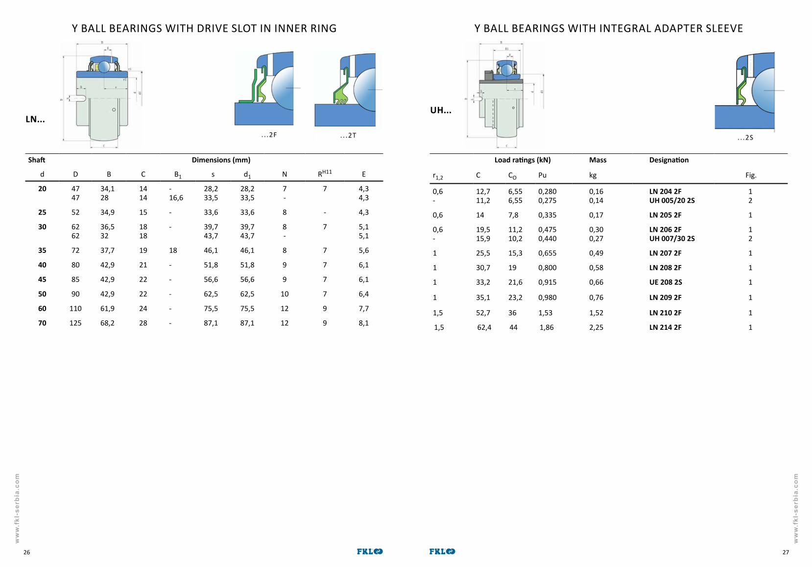
Y BALL BEARINGS WITH INTEGRAL ADAPTER SLEEVE
UH...
Load ratings (kN) Mass Designation
r1,2 C CO Pu kg Fig.
0,6-
12,711,2
6,556,55
0,2800,275
0,160,14
LN 204 2FUH 005/20 2S
12
0,6 14 7,8 0,335 0,17 LN 205 2F 1
0,6-
19,515,9
11,210,2
0,4750,440
0,300,27
LN 206 2FUH 007/30 2S
12
1 25,5 15,3 0,655 0,49 LN 207 2F 1
1 30,7 19 0,800 0,58 LN 208 2F 1
1 33,2 21,6 0,915 0,66 UE 208 2S 1
1 35,1 23,2 0,980 0,76 LN 209 2F 1
1,5 52,7 36 1,53 1,52 LN 210 2F 1
1,5 62,4 44 1,86 2,25 LN 214 2F 1
Y BALL BEARINGS WITH DRIVE SLOT IN INNER RING
LN...
Shaft Dimensions (mm)
d D B C B1 s d1 N RH11 E
20 4747
34,128
1414
-16,6
28,233,5
28,233,5
7-
7 4,34,3
25 52 34,9 15 - 33,6 33,6 8 - 4,3
30 6262
36,532
1818
- 39,743,7
39,743,7
8-
7 5,15,1
35 72 37,7 19 18 46,1 46,1 8 7 5,6
40 80 42,9 21 - 51,8 51,8 9 7 6,1
45 85 42,9 22 - 56,6 56,6 9 7 6,1
50 90 42,9 22 - 62,5 62,5 10 7 6,4
60 110 61,9 24 - 75,5 75,5 12 9 7,7
70 125 68,2 28 - 87,1 87,1 12 9 8,1

ww
w.f
kl-s
erbi
a.co
m
ww
w.f
kl-s
erbi
a.co
m
2928
Y BALL BEARINGS WITH EXTENDED STANDARD INNER RING
LS...
Shaft Dimensions (mm)
d2 d D L B C d1 W Y E
20 25 52 35 24 15 33,6 38 8 4,3
25 2530
5262
-38
2428
1518
33,639,7
-45
-8
4,35,1
30 3035
6272
-43
2830,5
1819
39,746,1
-52
-9
5,15,6
35 3540
7280
-46
30,533,9
1921
46,151,8
-58
-10
5,66,1
40 4045
8085
-50
33,935
2122
51,856,6
-65
-11
6,16.1
45 4550
8590
-55
3537
2222
56,662,5
-70
-12
6,16,4
50 5055
90100
-59
3740
2225
62,569,1
-75
-12
6,47
55 5560
100110
-62
4042,5
2526
69,175,5
-80
-13
77,7
60 65 120 65 43,5 27 82,5 85 14 7,6
65 75 130 73 47,5 29 92,1 98 15 8,1
70 80 140 78 49 30 97,4 105 17 8,3
75 85 150 82 56 34 97,4 110 18 8,2
80 90 160 86 58 36 105 120 19 9,3
Y BALL BEARING WITH TAPERED BOREY BALL BEARINGS WITH ADAPTER SLEEVE
LK...LK...+H...
Load ratings (kN) Mass Designation Mass Designation Mass Designation
C CO Pu kg kg 2 kg 3
14 7,8 0,335 0,13 LK 205 2F 0,22 LK 205 2F+H 2305
1419,5
7,811,2
0,3350,475
0,14 LS 205 2F 0,22 LK 206 2F 0,33 LK 206 2F+H 2306
19,525,5
11,215,3
0,4750,655
0,23 LS 206 2F 0,29 LK 207 2F 0,47 LK 207 2F+H 2307
25,530,7
15,319
0,6550,800
0,31 LS 207 2F 0,41 LK 208 2F 0,63 LK 208 2F+H 2308
30,733,2
1921,6
0,8000,915
0,43 LS 208 2F 0,47 LK 209 2F 0,73 LK 209 2F+H 2309
33,235,1
21,623,2
0,9150,980
0,49 LS 209 2S 0,51 LK 210 2F 0,86 LK 210 2F+H 2310
35,143,6
23,229
0,9801,25
0,54 LS 210 2F 0,75 LK 211 2F 1,10 LK 211 2F+H 2311
43,652,7
2936
1,251,53
0,79 LS 211 2F 1,05 LK 212 2F 1,40 LK 212 2F+H 2312
57,2 40 1,70 1,30 LK 213 2F 1,70 LK 213 2F+H 2313
66,3 49 2,04 1,64 LK 215 2F 2,35 LK 215 2F+H 2315
72,8 53 2,16 2,05 LK 216 2F 3,00 LK 216 2F+H 2316
85 65 2,50 2,41 LK 217 2F 3,55 LK 217 2F+H 2317
95,6 72 2,70 3,05 LK 218 2F 4,20 LK 218 2F+H 2318

ww
w.f
kl-s
erbi
a.co
m
ww
w.f
kl-s
erbi
a.co
m
3130
Y BEARING PLUMMER BLOCK UNITS – GREY CAST IRON HOUSING "S"
UES...LES...UYS...LYS...LSS...LKS...LCS...
Shaft Dimensions (mm) Mass Designationd A A1 H H1 H2 Jmin. Jmax. L N N1 s1 fig. kg
17 32 18 56,2 30,2 14 88 106 127 11,5 20,5 15,915,922,123,4
1234
0,480,500,520,54
UES 203 2SLES 203 2FUYS 203 2SLYS 203 2F
20 34
38
23
24
63,8
69,5
33,3
36,5
14
16
89
94
104,5
111
127
140
13
13
20,7
21,5
18,318,323,526,618,320
123467
0,550,570,590,620,620,77
UES 204 2SLES 204 2FUYS 204 2SLYS 204 2FLCS 204 2FLKS 205 2F + H2305
25 38
42
24
27
69,5
81,4
36,5
42,9
16
16
94
111
111
125
140
165
13
17
21,5
24
19,519,823,526,91219,822
1234567
0,700,730,730,780,700,791,15
UES 205 2SLES 205 2FUYS 205 2SLYS 205 2FLSS 205 2F LCS 205 2FLKS 206 2F + H2306
30 42
46
27
28
81,4
92,1
42,9
47,6
16
17
111
122
125
136
165
167
17
17
24
24
2122.226,730,11422,224,3
1234567
1,061,121,121,191,061,221,55
UES 206 2SLES 206 2FUYS 206 2SLYS 206 2FLSS 206 2F LCS 206 2FLKS 207 2F + H2307
35 46
49
28
31
92,1
98,2
47,6
49,2
17
18
122
128
136
145
167
184
17
17
24
25,5
23,325,529,432,315,225,527
1234567
1,461,531,5832,31,471,641,90
UES 207 2SLES 207 2FUYS 207 2SLYS 207 2FLSS 207 2F LCS 207 2FLKS 208 2F + H2308
40 49
52
31
36
98,2
107
49,2
54
18
20
128
136
145
151
184
190
17
17
25,5
23,5
25,330,232,734,9173028,5
1234567
1,851,961,992,081,882,112,35
UES 208 2SLES 208 2FUYS 208 2SLYS 208 2FLSS 208 2F LCS 208 2FLKS 209 2F + H2309
45 52 36 107 54 20 136 151 190 17 23,5 25,830,232,7
123
2,232,342,34
UES 209 2SLES 209 2FUYS 209 2S
Shaft Dimensions (mm) Mass Designationd A A1 H H1 H2 Jmin. Jmax. L N N1 s1 fig. kg
45 52 36 107 54 20 136 151 190 17 23,5 34,917,530,230,5
4567
2,462,252,482,85
LYS 209 2FLSS 209 2FLCS 209 2FLKS 210 2F + H2310
50 58 38 113,2 57,2 22 151 164 206 20 26,5 27,6 1234567
2,592,742,732,922,652,943,75
UES 210 2SLES 210 2FUYS 210 2SLYS 210 2FLSS 210 2FLCS 210 2FLKS 211 2F + H2311
55 60
65
24
47
69,5
136,8
36,5
69,8
16
26,5
94
179
111
198
140
241
13
20
21,5
29,5
33,435,943,621,233,434,3
234567
3,623,593,803,593,904,55
LES 211 2FUYS 211 2SLYS 211 2FLSS 211 2F LCS 211 2FLKS 212 2F + H2312
60 65
70
47
49
136,8
150
69,8
76,2
26,5
27
179
193
198
213
241
265
20
25
29,5
35
39,740,346,839,735,8
23467
4,624,194,825,015,70
LES 212 2FUYS 212 2SLYS 212 2FLCS 212 2FLKS 213 2F + H2313
65 70
74
49
54
150
165
76,2
82,5
27
28
193
209
213
225
265
275
25
25
35
33
42,951,642,938,8
2467
6,026,556,427,55
LES 213 2FLYS 213 2FLCS 213 2FLKS 215 2F + H2315
70 72
78
46
50
155
175
79,4
88,9
27
30
205
222
215
242
266
292
25
25
30
35
39,751,641,5
247
6,607,109,50
LES 214 2FLYS 214 2FLKS 216 2F + H2316
75 74 54 165 82,5 28 209 225 275 25 33 46,354,8
24
7,808,40
LES 215 2FLYS 215 2F
80 78
88
50
54
175
200
88,9
101,6
30
33
222
254
242
270
292
327
25
27
35
35
47,659,647
247
9,2010,013,7
LES 216 2FLYS 216 2FLKS 218 2F + H2318
90 88 54 200 101,6 33 254 270 327 27 35 5462,8
24
13,714,6
LES 218 2FLYS 218 2F
100 95 57 225 115 38 286 330 380 26 48 63,449,5
24
17,817,4
LES 220 2FLYS 220 2F
(2) (3) (4) (5) (6) (7)
3.4.1
(1)

ww
w.f
kl-s
erbi
a.co
m
ww
w.f
kl-s
erbi
a.co
m
3332
Y BEARING PLUMMER BLOCK UNIT – GREY CAST IRON HOUSING "V"
UEV...LEV...UYV...LYV...LSV...LKV...LCV...
Shaft Dimensions (mm) Mass Designationd L A J H G G1 H1 H2 A1 s1 fig. kg
20 76
84
38
38
52
56
30,2
36,5
M10
M10
12
15
8
10
62
72
24
25
18,318,323,526,618,320
123467
0,520,540,560,590,590,74
UEV 204 2SLEV 204 2FUYV 204 2SLYV 204 2FLCV 204 2FLKV 205 2F + H2305
25 84
94
38
48
56
66
36,5
42,9
M10
M14
15
18
10
10
72
84
25
28,5
19,519,823,526,91219,822
1234567
0,650,680,680,730,650,741,13
UEV 205 2SLEV 205 2FUYV 205 2SLYV 205 2FLSV 205 2FLCV 205 2FLKV 206 2F + H2306
30 94
110
48
48
66
80
42,9
47,6
M14
M14
18
20
10
12
84
95
28,5
30,5
2122,226,730,11422,224,3
1234567
0,971,031,031,100,971,131,53
UEV 206 2SLEV 206 2FUYV 206 2SLYV 206 2FLSV 206 2F LCV 206 2FLKV 207 2F + H2307
35 110
116
48
54
80
84
47,6
49,2
M14
M14
20
20
12
12
95
1000
30,5
31,5
23,325,529,432,315,225,527
1234567
1,371,441,491,571,381,551,76
UEV 207 2SLEV 207 2FUYV 207 2SLYV 207 2FLSV 207 2F LCV 207 2FLKV 208 2F + H2308
Shaft Dimensions (mm) Mass Designationd L A J H G G1 H1 H2 A1 s1 fig. kg
40 116
120
54
54
84
90
49,2
54,2
M14
M14
20
25
12
12
100
108
31,5
33,5
25,330,232,734,9173028,5
1234567
0,561,671,701,791,591,822,04
UEV 208 2SLEV 208 2FUYV 208 2SLYV 208 2FLSV 208 2F LCV 208 2FLKV 209 2F + H2309
45 120
130
54
60
90
94
54,2
57,2
M14
M16
25
25
12
14
108
116
33,5
35,5
25,830,232,734,917,530,230,5
1234567
1,801,911,891,911,822,052,53
UEV 209 2SLEV 209 2FUYV 209 2SLYV 209 2FLSV 209 2FLCV 209 2FLKV 210 2F + H2310
50 130 60 94 57,2 M16 25 14 116 35,5 27,632,632,738,12032,6
123456
2,182,332,322,512,242,54
UEV 210 2SLEV 210 2FUYV 210 2SLYV 210 2FLSV 210 2F LCV 210 2F
(1) (2) (3) (4) (5) (6) (7)
3.4.2
ww
w.f
kl-s
erbi
a.co
m
ww
w.f
kl-s
erbi
a.co
m
3534
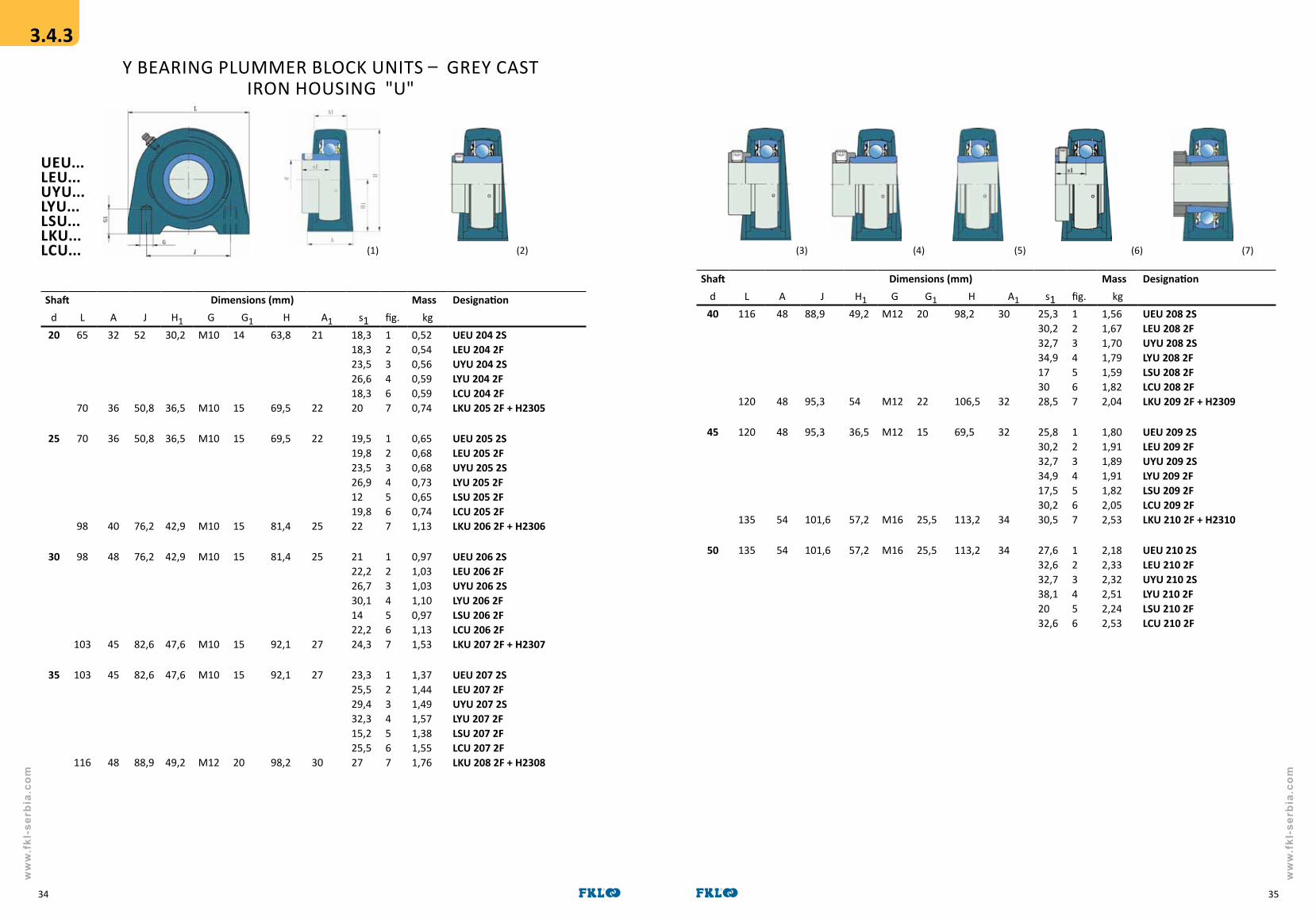
Y BEARING PLUMMER BLOCK UNITS – GREY CAST IRON HOUSING "U"
UEU...LEU...UYU...LYU...LSU...LKU...LCU...
Shaft Dimensions (mm) Mass Designationd L A J H1 G G1 H A1 s1 fig. kg
20 65
70
32
36
52
50,8
30,2
36,5
M10
M10
14
15
63,8
69,5
21
22
18,318,323,526,618,320
123467
0,520,540,560,590,590,74
UEU 204 2SLEU 204 2FUYU 204 2SLYU 204 2FLCU 204 2FLKU 205 2F + H2305
25 70
98
36
40
50,8
76,2
36,5
42,9
M10
M10
15
15
69,5
81,4
22
25
19,519,823,526,91219,822
1234567
0,650,680,680,730,650,741,13
UEU 205 2SLEU 205 2FUYU 205 2SLYU 205 2FLSU 205 2FLCU 205 2FLKU 206 2F + H2306
30 98
103
48
45
76,2
82,6
42,9
47,6
M10
M10
15
15
81,4
92,1
25
27
2122,226,730,11422,224,3
1234567
0,971,031,031,100,971,131,53
UEU 206 2SLEU 206 2FUYU 206 2SLYU 206 2FLSU 206 2F LCU 206 2FLKU 207 2F + H2307
35 103
116
45
48
82,6
88,9
47,6
49,2
M10
M12
15
20
92,1
98,2
27
30
23,325,529,432,315,225,527
1234567
1,371,441,491,571,381,551,76
UEU 207 2SLEU 207 2FUYU 207 2SLYU 207 2FLSU 207 2F LCU 207 2FLKU 208 2F + H2308
Shaft Dimensions (mm) Mass Designationd L A J H1 G G1 H A1 s1 fig. kg
40 116
120
48
48
88,9
95,3
49,2
54
M12
M12
20
22
98,2
106,5
30
32
25,330,232,734,9173028,5
1234567
1,561,671,701,791,591,822,04
UEU 208 2SLEU 208 2FUYU 208 2SLYU 208 2FLSU 208 2F LCU 208 2FLKU 209 2F + H2309
45 120
135
48
54
95,3
101,6
36,5
57,2
M12
M16
15
25,5
69,5
113,2
32
34
25,830,232,734,917,530,230,5
1234567
1,801,911,891,911,822,052,53
UEU 209 2SLEU 209 2FUYU 209 2SLYU 209 2FLSU 209 2FLCU 209 2FLKU 210 2F + H2310
50 135 54 101,6 57,2 M16 25,5 113,2 34 27,632,632,738,12032,6
123456
2,182,332,322,512,242,53
UEU 210 2SLEU 210 2FUYU 210 2SLYU 210 2FLSU 210 2F LCU 210 2F
(2) (3) (4) (5) (6) (7)
3.4.3
(1)

ww
w.f
kl-s
erbi
a.co
m
ww
w.f
kl-s
erbi
a.co
m
3736
Shaft Dimensions (mm) Mass Designationd A1 A2 J L N A fig. kg
45 38
40
16
15
105
111
137
143
16
16
56,939,552,252,5
4567
2,312,102,332,80
LYF 209 2FLSF 209 2FLCF 209 2F 210 2F + H2310
50 40
43
15
17
111
130
143
162
16
19
49,654,654,760,140,554,657,5
1234567
2,432,582,572,762,492,783,60
UEF 210 2F LEF 210 2FUYF 210 2SLYF 210 2FLSF 210 2FLCF 210 2FLKF 211 2F + H2311
55 43
48
17
18
130
83
162
175
19
19
58,460,968,64558,463,3
234567
3,423,393,603,393,704,60
LEF 211 2FUYF 211 2SLYF 211 2FLSF 211 2F LCF 211 2FLKF 212 2F + H2312
60 48
50
18
18
143
143
175
187
19
19
68,769,375,868,765,8
23467
4,273,844,474,666,00
LEF 212 2FUYF 212 2FLYC 212 2FLCF 212FLKF 213 2F + H2313
65 50
50,3
22
21,3
149
152
187
193
19
19
72,981,672,973,7
2467
5,576,105,977,00
LEF 213 2FLYF 213 2FLCF 213 2FLKF 215 2F + H2315
70 50,3
53,6
21,3
22,1
152
159
193
200
19
19
70,782,676,5
247
6,206,707,80
LEF 214 2FLYF 214 2FLKF 216 2F + H2316
75 53,6 22,1 159 200 19 80,388,8
24
7,007,60
LEF 215 2FLYF 215 2S
80 54,5
63,4
22
23,4
165
184
208
235
23
23
81,693,688,6
247
7,508,3411,6
LEF 216 2FLYF 216 2FLKF 218 2F + H2318
90 63,4 23,4 187 235 23 94,0102,8
24
11,612,5
LEF 218 2FLYF 218 2F
100 70 25 210 265 27 107,593,6
24
13,913,5
LEF 220 2FLYF 220 2F
Y FLANGED BEARING UNITS – SqUARE GREY CAST IRON HOUSING "F"
UEF...LEF...UYF...LYF...LSF...LKF...LCF...Shaft Dimensions (mm) Mass Designation
d A1 A2 J L N A fig. kg17 26 11 54 76 11,5 32,9
32,939,140,4
1234
0,420,440,460,48
UEF 203 2SLEF 203 2FUYF 203 2SLYF 203 2F
20 25,5
27
11
12
64
70
86
95
12
12
33,333,338,541,633,339
123456
0,520,540,560,590,590,73
UEF 204 2SLEF 204 2FUYF 204 2SLYF 204 2FLCF 204 2FLKF 205 2F + H2305
25 27
31
13
13
83
83
95
108
12
14
35,535,839,542,92835,840
1234567
0,700,730,730,780,700,791,05
UEF 205 2SLEF 205 2FUYF 205 2SLYF 205 2FLSF 205 2F LCF 205 2FLKF 206 2F + H2306
30 31
34
13
13
83
92
108
118
14
14
3940,244,748,13240,243,3
1234567
0,941,001,001,070,941,101,35
UEF 206 2SLEF 206 2FUYF 206 2SLYF 206 2FLSF 206 2F LCF 206 2FLKF 207 2F + H2307
35 34
36
13
14
92
102
118
130
14
16
42,344,548,451,334,344,548
1234567
1,271,341,391,471,281,451,75
UEF 207 2SLEF 207 2FUYF 207 2SLYF 207 2FLSF 207 2F LCF 207 2FLKF 208 2F + H2308
40 36
38
14
16
102
105
130
137
16
16
46,351,253,752,2385150,5
1234567
1,681,791,821,911,711,942,10
UEF 208 2SLEF 208 2FUYF 208 2SLYF 208 2FLSF 208 2F LCF 208 2FLKF 209 2F + H2309
45 38 16 105 137 16 47,852,254,7
123
2,082,192,19
UEF 209 2SLEF 209 2FUYF 209 2S
(1) (2) (3) (4) (5) (6) (7)
3.4.4
ww
w.f
kl-s
erbi
a.co
m
ww
w.f
kl-s
erbi
a.co
m
3938
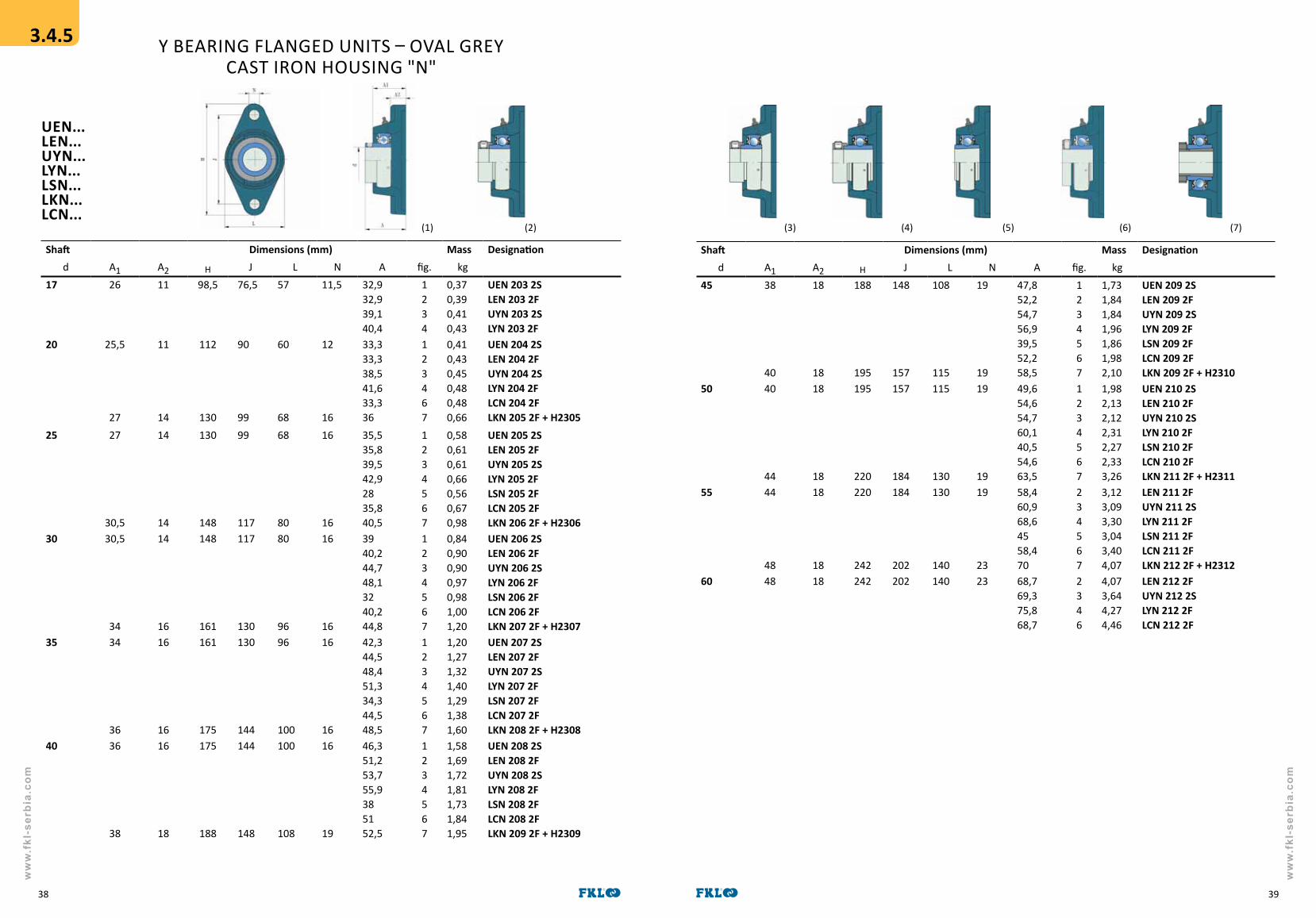
Shaft Dimensions (mm) Mass Designationd A1 A2 H J L N A fig. kg
45 38
40
18
18
188
195
148
157
108
115
19
19
47,852,254,756,939,552,258,5
1234567
1,731,841,841,961,861,982,10
UEN 209 2SLEN 209 2FUYN 209 2SLYN 209 2FLSN 209 2FLCN 209 2FLKN 209 2F + H2310
50 40
44
18
18
195
220
157
184
115
130
19
19
49,654,654,760,140,554,663,5
1234567
1,982,132,122,312,272,333,26
UEN 210 2SLEN 210 2FUYN 210 2SLYN 210 2FLSN 210 2FLCN 210 2FLKN 211 2F + H2311
55 44
48
18
18
220
242
184
202
130
140
19
23
58,460,968,64558,470
234567
3,123,093,303,043,404,07
LEN 211 2FUYN 211 2SLYN 211 2FLSN 211 2F LCN 211 2FLKN 212 2F + H2312
60 48 18 242 202 140 23 68,769,375,868,7
2346
4,073,644,274,46
LEN 212 2FUYN 212 2SLYN 212 2FLCN 212 2F
Y BEARING FLANGED UNITS – OVAL GREY CAST IRON HOUSING "N"
UEN...LEN...UYN...LYN...LSN...LKN...LCN...
Shaft Dimensions (mm) Mass Designationd A1 A2 H J L N A fig. kg
17 26 11 98,5 76,5 57 11,5 32,932,939,140,4
1234
0,370,390,410,43
UEN 203 2SLEN 203 2FUYN 203 2SLYN 203 2F
20 25,5
27
11
14
112
130
90
99
60
68
12
16
33,333,338,541,633,336
123467
0,410,430,450,480,480,66
UEN 204 2SLEN 204 2FUYN 204 2SLYN 204 2FLCN 204 2FLKN 205 2F + H2305
25 27
30,5
14
14
130
148
99
117
68
80
16
16
35,535,839,542,92835,840,5
1234567
0,580,610,610,660,560,670,98
UEN 205 2SLEN 205 2FUYN 205 2SLYN 205 2FLSN 205 2F LCN 205 2FLKN 206 2F + H2306
30 30,5
34
14
16
148
161
117
130
80
96
16
16
3940,244,748,13240,244,8
1234567
0,840,900,900,970,981,001,20
UEN 206 2SLEN 206 2FUYN 206 2SLYN 206 2FLSN 206 2F LCN 206 2FLKN 207 2F + H2307
35 34
36
16
16
161
175
130
144
96
100
16
16
42,344,548,451,334,344,548,5
1234567
1,201,271,321,401,291,381,60
UEN 207 2SLEN 207 2FUYN 207 2SLYN 207 2FLSN 207 2F LCN 207 2FLKN 208 2F + H2308
40 36
38
16
18
175
188
144
148
100
108
16
19
46,351,253,755,9385152,5
1234567
1,581,691,721,811,731,841,95
UEN 208 2SLEN 208 2FUYN 208 2SLYN 208 2FLSN 208 2F LCN 208 2FLKN 209 2F + H2309
(1) (2) (3) (4) (5) (6) (7)
3.4.5

ww
w.f
kl-s
erbi
a.co
m
ww
w.f
kl-s
erbi
a.co
m
4140
Y BEARING FLANGED UNITS – ROUND GREY CAST IRON HOUSING "G"
UEG...LEG...UYG...LYG...LSG...LKG...LCG...
Shaft Dimensions (mm) Mass Designationd A1 A2 A3 Da J J1 L N A fig. kg
20 25,5
27
7
7
5
6
62
70
78
90
55,1
63,6
100
115
12
12
28,328,333,536,628,330
123467
0,650,670,690,720,720,78
UEG 204 2SLEG 204 2FUYG 204 2SLYG 204 2FLCG 204 2FLKG 205 2F + H2305
25 27
31
7
8
6
8
70
80
90
100
63,6
70,7
115
125
12
12
29,529,533,536,920,529,832
1234567
0,950,980,981,030,931,041,45
UEG 205 2SLEG 205 2FUYG 205 2SLYG 205 2FLSG 205 2F LCG 205 2FLKG 206 2F + H2306
30 31
34
8
9
8
8
80
90
100
110
70,7
77,8
125
135
12
14
3132,236,740,12332,235,3
1234567
1,341,401,401,471,481,501,60
UEG 206 2SLEG 206 2FUYG 206 2SLYG 206 2FLSG 206 2F LCG 206 2FLKG 207 2F + H2307
35 34
36
9
9
8
10
90
100
110
120
77,8
84,8
135
145
14
14
34,336,540,443,323,836,538,5
1234567
1,571,641,691,771,661,752,10
UEG 207 2SLEG 207 2FUYG 207 2SLYG 207 2FLSG 207 2F LCG 207 2FLKG 208 2F + H2308
40 36
38
9
14
10
12
100
105
120
132
84,8
93,3
145
160
14
16
36,341,243,745,924,54138,5
1234567
1,781,891,922,011,932,042,75
UEG 208 2SLEG 208 2FUYG 208 2SLYG 208 2FLSG 208 2F LCG 208 2FLKG 209 2F + H2309
Shaft Dimensions (mm) Mass Designationd A1 A2 A3 Da J J1 L N A fig kg
45 38
40
14
14
12
12
105
110
132
138
93,3
97,6
160
165
16
16
35,840,242,744,92440,240
1234567
2,532,642,642,762,662,583,00
UEG 209 2SLEG 209 2FUYG 209 2SLYG 209 2FLSG 209 2F LCG 209 2FLKG 210 2F + H2310
50 40
43
14
15
12
12
110
125
138
150
97,6
106,1
165
185
16
19
37,642,642,748,12442,657
1234567
2,782,932,923,113,073,133,26
UEG 210 2SLEG 210 2FUYG 210 2SLYG 210 2FLSG 210 2F LCG 210 2FLKG 211 2F + H2311
55 43
48
15
15
12
12
125
135
150
160
106,1
113,1
185
195
19
19
46,448,956,627,546,459
234567
4,074,044,253,994,354,07
LEG 211 2FUYG 211 2SLYG 211 2FLSG 211 2F LCG 211 2FLKG 212 2F + H2312
60 48 15 12 135 160 113,1 195 19 56,757,363,856,7
2346
5,024,595,225,41
LEG 212 2FUYG 212 2SLYG 212 2FLCG 212 2F
65 50 15 14 145 170 120,2 205 19 58,967,6
24
5,856,59
LEG 213 2FLYG 213 2F
3.4.6
(1) (2) (3) (4) (5) (6) (7)

ww
w.f
kl-s
erbi
a.co
m
ww
w.f
kl-s
erbi
a.co
m
4342
Y BEARING TAKE – UP UNITS - GREY CAST IRON HOUSINGS "T", "TJ"
UET(J)...LET(J)...UYT(J)...LYT(J)...LST(J)...LKT(J)...
Shaft Dimensions (mm) Mass Designationd A A2 Da H L L1 L2 N N1 A1 H1 s1 fig. kg
20 34
34
52
25
19
19
92
91
97
100
62
64
16
16
32
33
10
10
13,5
13,5
76
76
18,318,323,526,623,5
12346
0,890,910,930,960,94
UET 204 2SLET 204 2FUYT 204 2SLYT 204 2FLKT 205 2F + H2305
34
34
25
25
19
19
91
104
100
114
62
64
16
16
32
33
10
10
12
13,5
76
76
18,318,323,526,623,5
12346
0,890,910,930,960,94
UETJ 204 2SLETJ 204 2FUYTJ 204 2SLYTJ 204 2FLKTJ 205 2F + H2305
25 34
37
25
28
19
22
91
104
100
114
64
70
16
16
33
37
10
10
13,5
13,5
76
89
19,519,823,516,911,525
123456
0,850,880,880,930,851,37
UET 205 2SLET 205 2FUYT 205 2SLYT 205 2FLST 205 2F LKT 206 2F + H2306
34
37
25
28
19
22
91
104
100
114
64
70
16
16
33
37
10
10
12
12
76
89
19,519,823,526,911,525
123456
0,850,880,880,930,851,37
UETJ 205 2SLETJ 205 2FUYTJ 205 2SLYTJ 205 2FLSTJ 205 2F LKTJ 206 2F + H2306
30 37
37
28
30
22
22
104
103
114
129
70
78
16
17
37
38
10
12
13,5
13,5
89
89
2122,226,730,11329,5
123456
1,211,271,271,341,211,66
UET 206 2SLET 206 2FUYT 206 2SLYT 206 2FLST 206 2F LKT 207 2F + H2307
Shaft Dimensions (mm) Mass Designationd A A2 Da H L L1 L2 N N1 A1 H1 s1 fig. kg
30 37
37
28
30
22
22
104
103
114
129
70
78
16
17
37
38
10
12
12
12
89
89
2122,226,730,11329,5
123456
1,21 1,271,271,341,211,66
UETJ 206 2SLETJ 206 2FUYTJ 206 2SLYTJ 206 2FLSTJ 206 2FLKTJ 207 2F + H2307
35 37
49
30
33
22
29
103
115
129
145
78
88
17
19
38
50
12
15
13,5
17,5
89
101
23,325,529,432,313,531,5
123456
1,501,571,621,701,51 2,43
UET 207 2SLET 207 2FUYT 207 2SLYT 207 2FLST 207 2FLKT 208 2F + H2308
37
49
30
33
22
29
103
115
145
145
78
88
17
19
38
50
12
15
12
16
89
102
23,325,529,432,313,531,5
123456
1,501,571,621,701,51 2,43
UETJ 207 2SLETJ 207 2FUYTJ 207 2SLYTJ 207 2FLSTJ 207 2F LKTJ 208 2F + H2308
40 49
49
33
35
29
29
115
117
145
144
88
87
19
19
50
49
15
15
17,5
17,5
101
101
25,330,232,734,914,535
123456
2,232,342,372,462,262,47
UET 208 2SLET 208 2FUYT 208 2SLYT 208 2FLST 208 2F LKT 209 2F + H2309
49
49
33
35
29
29
115
117
145
144
88
87
19
19
50
49
15
15
16
16
102
102
25,330,232,734,914,535
123456
2,232,342,372,462,262,47
UETJ 208 2SLETJ 208 2FUYTJ 208 2SLYTJ 208 2FLSTJ 208 2F LKTJ 209 2F + H2309
3.4.7
(1) (2) (3) (4) (5) (6)

ww
w.f
kl-s
erbi
a.co
m
ww
w.f
kl-s
erbi
a.co
m
4544
Y BEARING TAKE – UP UNITS - GREY CAST IRON HOUSINGS "T", "TJ"
UET(J)...LET(J)...UYT(J)...LYT(J)...LST(J)...LKT(J)...
Shaft Dimensions (mm) Mass Designationd A A2 Da H L L1 L2 N N1 A1 H1 s1 fig. kg
45 49
49
35
36
29
29
117
117
144
149
87
90
19
19
49
49
15
16
17,5
17,5
101
101
25,830,232,734,91539,5
123456
2,232,342,342,462,252,63
UET 209 2SLET 209 2FUYT 209 2SLYT 209 2FLST 209 2FLKT 210 2F + H2310
49
49
35
36
29
29
117
117
144
149
87
90
19
19
49
49
15
16
16
16
102
102
25,830,232,734,91539,5
123456
2,232,342,342,462,252,63
UETJ 209 2SLETJ 209 2FUYTJ 209 2SLYTJ 209 2FLSTJ 209 2FLKTJ 210 2F + H2310
50 49
64
36
41
29
35
117
146
149
171
90
106
19
25
49
64
16
19
17,5
27
101
130
27,632,632,738,115,542,5
123456
2,282,432,422,612,344,16
UET 210 2SLET 210 2FUYT 210 2SLYT 210 2FLST 210 2F LKT 211 2F + H2311
49
64
36
41
29
35
117
146
149
171
90
106
19
25
49
64
16
19
16
22
102
130
27,632,632,738,115,542,5
123456
2,282,432,422,612,344,16
UETJ 210 2SLETJ 210 2FUYTJ 210 2SLYTJ 210 2FLSTJ 210 2F LKTJ 211 2F + H2311
Shaft Dimensions (mm) Mass Designationd A A2 Da H L L1 L2 N N1 A1 H1 s1 fig. kg
55 64
64
41
41
35
35
146
146
171
171
106
106
25
25
64
64
19
19
27
22
130
130
33,435,943,616,5
2345
4,023,994,203,99
LET 211 2FUYT 211 2SLYT 211 2FLST 211 2F
64
64
41
44
35
35
146
146
171
186
106
118
25
32
64
64
19
19
22
22
130
130
33,435,943,616,544
23456
4,023,994,203,994,67
LETJ 211 2FUYTJ 211 2SLYTJ 211 2FLSTJ 211 2FLKTJ 212 2F + H2312
60 64 44 35 146 186 118 32 64 19 22 130 39,740,346,8
234
4,674,244,87
LETJ 212 2FUYTJ 212 2SLYTJ 212 2F
(1) (2) (3) (4) (5) (6)

ww
w.f
kl-s
erbi
a.co
m
ww
w.f
kl-s
erbi
a.co
m
4746
Shaft Dimensions (mm) Perm. load (kN) Mass Designationd A1 A2 Da H J N A rad. axial fig. kg
40 3,5 11 91 148 119 13,5 28,833,736,238,4
7,5 3,7 1234
1,161,271,301,39
UEC 208 2SLEC 208 2FUYC 208 2SLYC 208 2F
45 3,5 11,5 96 149 120,5 13,5 29,333,736,238,4
8,3 4,1 1234
1,231,341,341,46
UEC 209 2SLEC 209 2FUYC 209 2SLYC 209 2F
50 4 2 102 155 127 13,5 31,636,636,742,1
9 4,5 1234
1,441,591,581,77
UEC 210 2SLEC 210 2FUYC 210 2SLYC 210 2F
55 4 12,5 112 167 138 13,5 37,439,947,6
9,5 4,8 234
2,021,992,20
LEC 211 2FUYC 211 2SLYC 211 2F
60 4 13 122 176 148 13,5 43,744,350,8
9,5 4,8 234
2,672,242,87
LEC 212 2FUYC 212 2SLYC 212 2F
Y BEARING FLANGED UNITS – ROUND PRESSED STEEL HOUSING "C"
UEC...LEC...UYC...LYC...
Shaft Dimensions (mm) Perm. load (kN) Mass Designationd A1 A2 Da H J N A rad. axial fig. kg
17 2
2
7
8
49
55
81
91
63
71,5
7,1
8,7
17,917,924,124,3
2,5 1,2 1234
0,200,220,240,26
UEC 203 2SLEC 203 2FUYC 203 2SLYC 203 2F
20 2 8 55 91 71,5 8,7 20,320,325,528,6
3,3 1,6 1234
0,280,300,320,35
UEC 204 2SLEC 204 2FUYC 204 2SLYC 204 2F
25 2 9 60 95 76 8,7 21,521,825,528,9
3,6 1,8 1234
0,330,360,360,41
UEC 205 2SLEC 205 2FUYC 205 2SLYC 205 2F
30 2,5 9,5 71 112 90,5 10,5 23,524,729,232,6
5,0 2,5 1234
0,520,580,580,65
UEC 206 2SLEC 206 2FUYC 206 2SLYC 206 2F
35 2,5 10,5 81 122 100 10,5 25,82831,934,8
6,5 3,2 1234
0,690,760,810,89
UEC 207 2SLEC 207 2FUYC 207 2SLYC 207 2F
HOUSING C 208 AND LARGER HAVE 4 LOCKING HOLES.
ALL COMBINATIONS WITH OTHER TYPES OF Y BEARINGS ARE POSSIBLE.
3.4.8
(1) (2) (3) (4)

ww
w.f
kl-s
erbi
a.co
m
ww
w.f
kl-s
erbi
a.co
m
4948
Shaft Dimensions (mm) Perm. load (kN) Mass Designationd A1 A2 Da H H1 J N A rad. axial fig. kg
30 2,5 9,5 71 112 38 90,5 10,5 23,524,729,232,6
5,0 2,5 1234
0,430,490,490,56
UED 206 2SLED 206 2FUYD 206 2SLYD 206 2F
35 2,5 10,5 81 122 45 100 10,5 25,82831,934,8
6,5 3,2 1234
0,650,720,770,85
UED 207 2SLED 207 2FUYD 207 2SLYD 207 2F
Y BEARING FLANGED UNITS – TRIANGULAR PRESSED
STEEL HOUSING "D"
UED...LED...UYD...LYD...
Shaft Dimensions (mm) Perm. load (kN) Mass Designationd A1 A2 Da H H1 J N A rad. axial fig. kg
17 2 7 49 81 29 63 7,1 17,917,924,124,3
2,5 1,2 1234
0,160,180,200,22
UED 203 2SLED 203 2FUYD 203 2SLYD 203 2F
20 2 8 55 91 32 71,5 8,7 20,320,325,528,6
3,3 1,6 1234
0,250,270,290,32
UED 204 2SLED 204 2FUYD 204 2SLYD 204 2F
25 2 9 60 95 34 76 8,7 21,521,825,528,9
3,6 1,8 1234
0,310,340,340,39
UED 205 2SLED 205 2FUYD 205 2SLYD 205 2F
ALL COMBINATIONS WITH OTHER TYPES OF Y BEARINGS ARE POSSIBLE.
3.4.9
(1) (2) (3) (4)

ww
w.f
kl-s
erbi
a.co
m
ww
w.f
kl-s
erbi
a.co
m
5150
Shaft Dimensions (mm) Perm. load (kN) Mass Designationd A1 A2 Da H L J N A rad. axial fig. kg
30 2,5 9,5 71 112 84 90,5 10,5 23,524,729,232,6
5,0 2,5 1234
0,400,460,460,53
UEP 206 2SLEP 206 2FUYP 206 2SLYP 206 2F
35 2,5 10,5 81 122 94 100 10,5 25,82831,934,8
6,5 3,2 1234
0,600,670,720,80
UEP 207 2SLEP 207 2FUYP 207 2SLYP 207 2F
40 3,5 11 91 148 100 119 13,5 28,833,736,238,4
7,5 3,7 1234
0,830,940,971,06
UEP 208 2SLEP 208 2FUYP 208 2SLYP 208 2F
Y BEARING FLANGED UNITS – OVAL PRESSED STEEL HOUSING "P"
UEP...LEP...UYP...LYP...
Shaft Dimensions (mm) Perm. load (kN) Mass Designationd A1 A2 Da H L J N A rad. axial fig. kg
17 2 7 49 81 59 63 7,1 17,917,924,124,3
2,5 1,2 1234
0,150,170,190,21
UEP 203 2SLEP 203 2FUYP 203 2SLYP 203 2F
20 2 8 55 91 67 71,5 8,7 20,320,325,528,6
3,3 1,6 1234
0,210,230,250,28
UEP 204 2SLEP 204 2FUYP 204 2SLYP 204 2F
25 2 9 60 95 71 76 8,7 21,521,825,528,9
3,6 1,8 1234
0,260,290,290,34
UEP 205 2SLEP 205 2FUYP 205 2SLYP 205 2F
ALL COMBINATIONS WITH OTHER TYPES OF Y BEARINGS ARE POSSIBLE.
3.4.10
(1) (2) (3) (4)

ww
w.f
kl-s
erbi
a.co
m
ww
w.f
kl-s
erbi
a.co
m
5352
Shaft Dimensions (mm) Perm. load Mass Designationd A A1 H H1 H2 J L N s1 rad. (kN) fig. kg
35 41 27 78 39,2 5 106 130 11,2 23,325,529,432,3
3,3 1234
0,680,750,800,88
UER 207 2SLER 207 2FUYR 207 2SLYR 207 2F
40 43 29 86 43,5 5 120 148 14 25,330,232,734,9
3,8 1234
0,880,991,021,11
UER 208 2SLER 208 2FUYR 208 2SLYR 208 2F
45 45 31 92 46,4 6 128 156 14 25,830,235,734,9
4,2 1234
0,931,041,041,16
UER 209 2SLER 209 2FUYR 209 2SLYR 209 2F
Y BEARING PLUMMER BLOCK UNITS - PRESSED STEEL HOUSING "R"
UER...LER...UYR...LYR...
Shaft Dimensions (mm) Perm. load Mass Designationd A A1 H H1 H2 J L N s1 rad. (kN) fig. kg
17 26 18 44 22 3 68 86 9,6 15,915,922,122,3
1,25 1234
0,140,160,180,20
UER 203 2SLER 203 2FUYR 203 2SLYR 203 2F
20 32 21 50 25,2 3 76 99 9,6 18,318,323,526,9
1,80 1234
0,250,280,280,33
UER 204 2SLER 204 2FUYR 204 2SLYR 204 2F
25 32 24 56 28,3 3,2 86 108 11,2 19,519,823,526,9
1,80 1234
0,250,280,280,33
UER 205 2SLER 205 2FUYR 205 2SLYR 205 2F
30 38 25 66 32,9 4 95 119 11,2 2122,226,730,1
2,6 1234
0,410,470,470,54
UER 206 2SLER 206 2FUYR 206 2SLYR 206 2F
ALL COMBINATIONS WITH OTHER TYPES OF Y BEARINGS ARE POSSIBLE.
3.4.11
(1) (2) (3) (4)

ww
w.f
kl-s
erbi
a.co
m
ww
w.f
kl-s
erbi
a.co
m
5554
TRIPLE-LIP SEALS – SPHERICAL OUTSIDE SURFACE ON OUTER RING – NON RELUBRICATABLE TYPE
Dimensions (mm)Bore d D B C d1
ich mm inch mm inch mm inch mm inch mm
1,50051,18801,18801,5005
38,11330,1730,1738,113
3,1496 80 1,6881,1881,1881,688
42,9630,1830,1842,96
0,7091,1880,7091,188
1830,181830,18
2,047 52
1,77171,53501,7811
453945,24
3,3465 85 1,1881,1881,438
30,1830,1836,53
1,1881,1880,866
30,1830,1822
2,228 56,6
1,93801,78112,1880
49,2345,3455,58
3,5433
3,39370
90
100
1,1881,1881,312
30,1830,1833,34
1,1881,1881,312
30,1830,1833,34
2,461
2,720
62,5
69,1
Shaft size a
1 1/811 1/81 7/81 1/8 7/8 7/81 1/8
28,625,428,625,422,228,622,222,228,6
3,14963,14963,14963,14963,37553,37553,14963,43853,4385
8080808085,7485,748087,3487,34
1,438 36,53 0,7090,7091,1881,1881,1881,1880,7091,1881,188
181830,1830,1830,1830,181830,1830,18
2,047 52
1 1/41 1/41 1/4--
31,831,831,83025
3,34653,43853,34653,54333,5433
8587,34859090
1,4381,4381,4381,7721,772
36,5336,5336,534545
1,1881,1880,7481,1421,142
30,1830,18192929
2,228 56,6
1 1/81 1/8
28,628,6
3,54333,5433
9090
1,1881,438
30,1836,53
1,1881,188
30,1830,18
2,461 62,5
1 1/21 1/21 1/2
38,138,138,1
3,93704,12504,0770
100104,77103,56
1,3121,7501,750
33,3444,4544,45
1,3121,4381,438
33,3436,5336,53
2,720 69,1
Load ratings (kN) CYLINDRICAL BORE
C Co MassIbs. kN Ibs. kN Ibs. kg Designation Type
7300 32,5 4400 19,8 1,591,601,411,50
0,720,730,640,68
W208PPB2W208PPB4W208PPB7W208PPB23
1311
7300 32,5 4600 20,4 1,441,651,34
0,650,750,62
W209PPB2W209PPB4W209PPB11
331
7800
9700
35,0
43,5
5200
6500
23,2
29,0
1,561,752,13
0,710,790,97
W210PPB2W210PPB5W211PPB2
333
SQUARE BORE
7300 32,5 4400 19,8 1,471,591,701,902,202,091,622,051,87
0,680,720,770,861,000,950,740,930,85
W208PPB5W208PPB6W208PPB8W208PPB9W208PPB11W208PPB12W208PPB13W208PPB18W208PPB19
112244144
7300 32,5 4600 20,4 1,751,851,652,512,91
0,790,840,751,141,32
W209PPB5W208PPB7W209PPB8W209PPB30W209PPB25
14144
7800 35,0 5200 23,2 2,112,25
0,961,02
W210PPB4W210PPB6
31
9700 43,5 6500 29,0 2,664,103,83
1,211,861,74
W211PPB3W211PPB5W211PPB6
344
3.4 DISC HARROW BEARINGS FIRST GENERATION

ww
w.f
kl-s
erbi
a.co
m
ww
w.f
kl-s
erbi
a.co
m
5756
DISC HARROW BEARINGS FIRST GENERATIONTRIPLE-LIP SEALS – CYLINDRICAL OUTSIDE SURFACE ON OUTER RING – NON
RELUBRICATABLE TYPE
Dimensions (mm)Bore d D B C d1
ich mm inch mm inch mm inch mm inch mm
1,18801,18801,5005
30,1730,1738,113
3,1496 80 1,1881,1881,687
30,1830,1842,85
1,1880,7090,827
30,181821
2,047 52
1,93801,53002,1880
49,2338,8655,58
3,5433
3,3970
90
100
1,1881,1881,312
30,1830,1833,34
1,1881,1881,312
30,1830,1833,34
2,461
2,720
62,5
69,1
Shaft size a
25 2,8346 72 1,771 45 0,945 24 1,815 46,1
1 1/411 1/81 1/8
31,825,428,628,6
3,1496 80 1,438 36,53 0,7090,7091,1880,709
181830,1818
2,047 52
30 3,3465 85 1,771 45 1,188 30,18 2,228 56,6
1 1/8 28,6 3,5433 90 1,188 30,18 1,188 30,18 2,461 62,5
1 1/21 1/2
38,138,1
3,93704
100101,6
1,3121,750
33,3444,45
1,3121,438
33,3436,52
2,720 69,1
Load ratings (kN) CYLINDRICAL BORE
C Co MassIbs. kN Ibs. kN Ibs. kg Designation Type
7300 32,5 4400 19,8 1,681,431,50
0,760,650,68
W208PP4W208PP7W208PP10
311
7800 35,0 5200 23,2 1,691,972,33
0,770,891,06
W210PP2W210PP9W211PP2
333
SQUARE BORE
5700 25,5 3400 15,3 1,65 0,75 W207PP3 1
7300 32,5 4400 19,8 1,501,621,662,50
0,680,730,750,68
W208PP5W208PP6W209PP8W209PP20
1111
7300 32,5 4600 20,4 2,16 0,98 W209PP3 2
7800 35,0 5200 23,2 1,92 0,87 W210PP4 3
9700 43,5 6500 29,0 2,793,48
1,271,58
W211PP3W211PP5
31
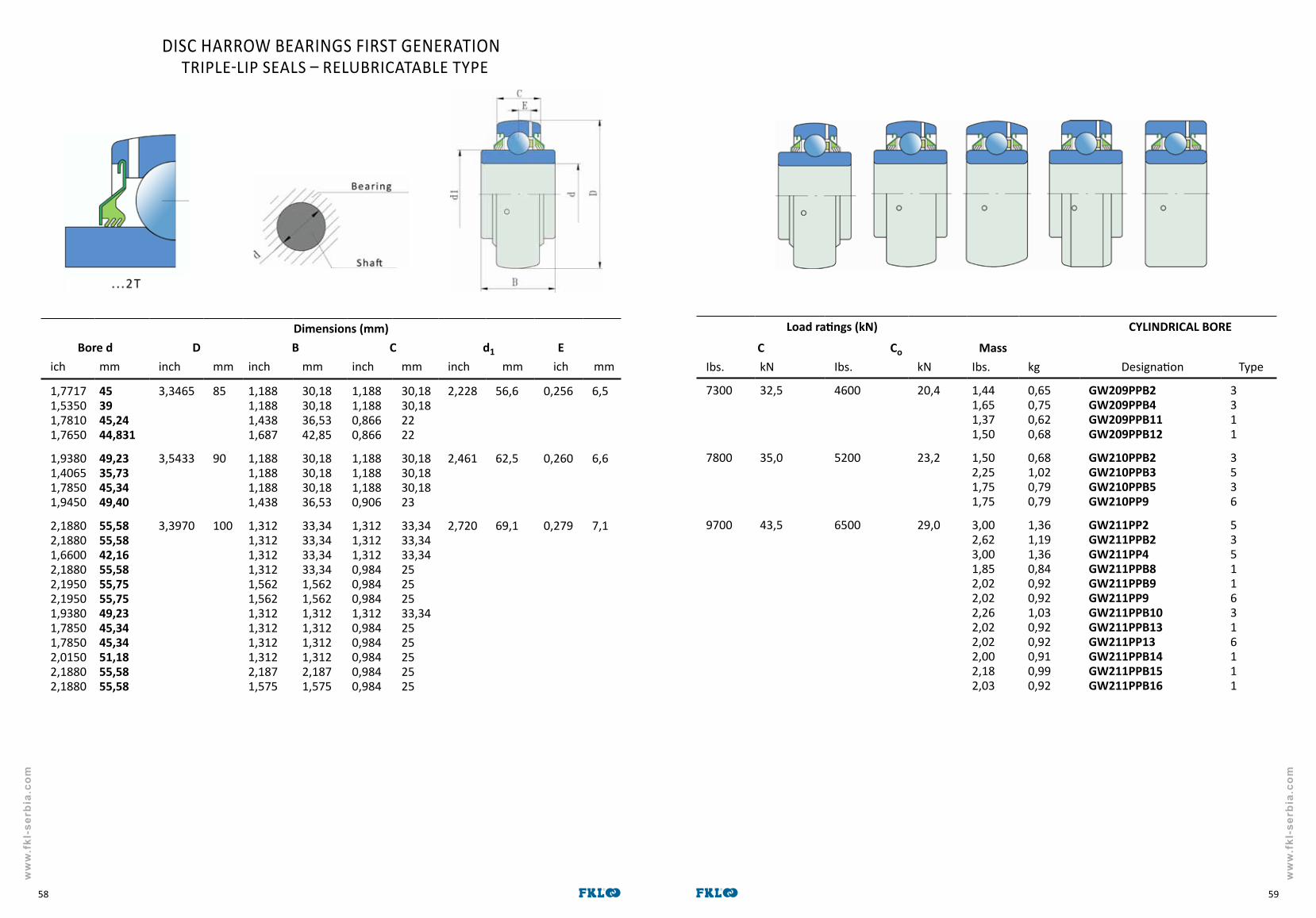
ww
w.f
kl-s
erbi
a.co
m
ww
w.f
kl-s
erbi
a.co
m
5958
DISC HARROW BEARINGS FIRST GENERATION TRIPLE-LIP SEALS – RELUBRICATABLE TYPE
Dimensions (mm)Bore d D B C d1 E
ich mm inch mm inch mm inch mm inch mm ich mm
1,77171,53501,78101,7650
453945,2444,831
3,3465 85 1,1881,1881,4381,687
30,1830,1836,5342,85
1,1881,1880,8660,866
30,1830,182222
2,228 56,6 0,256 6,5
1,93801,40651,78501,9450
49,2335,7345,3449,40
3,5433 90 1,1881,1881,1881,438
30,1830,18 30,1836,53
1,1881,1881,1880,906
30,1830,1830,1823
2,461 62,5 0,260 6,6
2,18802,18801,66002,18802,19502,19501,93801,78501,78502,01502,18802,1880
55,5855,5842,1655,5855,7555,7549,2345,3445,3451,1855,5855,58
3,3970 100 1,3121,3121,3121,3121,5621,5621,3121,3121,3121,3122,1871,575
33,3433,3433,3433,341,5621,5621,3121,3121,3121,3122,1871,575
1,3121,3121,3120,9840,9840,9841,3120,9840,9840,9840,9840,984
33,3433,3433,3425252533,342525252525
2,720 69,1 0,279 7,1
Load ratings (kN) CYLINDRICAL BORE
C Co MassIbs. kN Ibs. kN Ibs. kg Designation Type
7300 32,5 4600 20,4 1,441,651,371,50
0,650,750,620,68
GW209PPB2GW209PPB4GW209PPB11GW209PPB12
3311
7800 35,0 5200 23,2 1,502,251,751,75
0,681,020,790,79
GW210PPB2GW210PPB3GW210PPB5GW210PP9
3536
9700 43,5 6500 29,0 3,002,623,001,852,022,022,262,022,022,002,182,03
1,361,191,360,840,920,921,030,920,920,910,990,92
GW211PP2GW211PPB2GW211PP4GW211PPB8GW211PPB9GW211PP9GW211PPB10GW211PPB13GW211PP13GW211PPB14GW211PPB15GW211PPB16
535116316111

ww
w.f
kl-s
erbi
a.co
m
ww
w.f
kl-s
erbi
a.co
m
6160
Type 2.
Recommendations for max. loadradial
Ibs kNaxial
Ibs kNMass
Ibs kNType Designation
817 3,6 409 1,8 0,79 0,36 2 LEST 205 2F
1750 7,7 860 3,8 3,323,923,723,983,56
1,511,781,691,811,62
11111
GWST 209PPB12GWST 209PPB26GWST 209PPB31GWST 209PPB3GWST 209PPB40
2200 9,8 1150 5,1 4,514,954,55
2,052,252,07
111
GWST 211PPB15GWST 211PPB40LSST 211 X3-3
DISC HARROW BEARINGS FIRST GENERATION
Type 1.
Shaft size Dimensions (mm)a-square
mm inchd-cylindrical
boremm
B A A1 C Da L J N
0,9843 25 30 15 2 15 - 78 58 9,5
253030
1,7650
1,5748
44,831
40
42,8542,8542,85
4542,85
40 4 25,425,425,426,525,4
97 127 127 13,5
40,52,1880
2,1653
55,58
55
55,554555
44,7 4 31,826,531,5
113 140 140 13,5

ww
w.f
kl-s
erbi
a.co
m
ww
w.f
kl-s
erbi
a.co
m
6362
Load ratings NON RELUBRICATABLE TYPE
C Co Mass DesignationIbs. kN Ibs. kN Ibs. kg Seal Fig.a Type Seal Fig.b Type
3100 14,0 1700 7,8 0,440,440,44
0,200,200,20
205KRR2205KRRB2
31
205PPB13
4400 19,5 2500 11,3 0,760,760,750,75
0,350,350,340,34
206KRR6206KRRB6
31
206KPP3206KPPB3
31
5700 25,5 3400 15,3 1,000,871,000,870,870,87
0,450,400,450,400,400,40
207KPP3207KPPB3207KRRB9207KRRB12207KRR17207KRRB17
311131
7300 32,5 4400 19,8 1,451,45
0,660,66 W208KRR8 3
W208PPB16 1
7300 32,5 4600 20,4 1,27 0,58 209KRRB2 1
RELUBRICATABLE TYPE
4400 19,5 2500 11,3 0,620,610,59
0,280,280,27 G206KRRB6 2
G206KPP4G206KPPB4
42
5700 25,5 3400 15,3 1,00 0,45 G207KPPB2 2
7300 32,5 4400 19,8 1,401,50
0,640,68
GW208KRRB5 2GW208PPB22 2
DISC HARROW BEARINGS FIRST GENERATIONHEXAGONAL BORE
Dimesions (mm)
Shaft a t min. D B C d1 Einch inch mm inch mm inch mm inch mm inch mm inch mm inch mm
7/8 0,876 22,25 1,010 25,65 2,0472 52 1 25,4 0,591 15 1,323 33,6
1 1,001 25,43 1,152 29,26 2,4409 62 0,945 24 0,630 16 1,563 39,7
1 1/41 1/41 1/81 1/81 1/41 1/4
1,2511,2511,1261,1261,2511,251
31,7731,7728,628,631,7731,77
1,4431,4431,2981,2981,4431,443
36,3536,3532,9732,9736,3536,35
2,8346 72 1,4840,9841,4840,9840,9840,984
37,72537,7252525
0,669 17 1,815 46,1
1 1/4 1,251 31,77 1,443 36,65 3,1496 80 1,438 36,53 0,709 18 2,047 52
1 1/2 1,501 38,12 1,730 43,94 3,3456 85 1,181 30 0,748 19 2,228 56,6
1 1,001 25,43 1,152 29,26 2,4409 62 0,945 24 0,709 18 1,563 39,7 0,201 5,1
1 1/8 1,126 28,60 1,298 32,97 2,8346 72 1,484 37,7 0,748 19 1,815 46,1 0,220 5,6
1 1/41 1/4
1,2511,255
31,7731,88
1,4431,447
36,65 36,75
3,1496 80 1,438 36,53 0,827 21 2,047 52 0,236 6

ww
w.f
kl-s
erbi
a.co
m
ww
w.f
kl-s
erbi
a.co
m
6564
Development of modern agricultural machinery has increased the demand of bearings for soil preparation machinery. There is a requirement that each plate should have its own compact bearing, in order to reduce the costs of dismounting and mounting during maintenance, as well as request for better sealing and permanent lubrication of bearings.
DesignDesign of double row angular contact ball bearings for agricultural application has derived from the design of the wheel bearings. Rigid bearing arrangement needs reduced and constant axial clearance that does not depend on the skills of final user but is provided by design and bearing production technology.Rings and balls are made of special bearing steel.One bearing is mounted on a single plate.
Force As opposite from classical disc harrow bearings, these bearings can support both axial force and torque. Sealing and lubrication Bearing are permanently lubricated with grease for agricultural machinery at a rate of 60-80% of the free volume. These bearings have rubber-metal seals. It is also necessary to add the final sealing.
Fig.10. Mounting of disc harrow bearing
3.5 Disc harrow bearings second generation306230
FKL 306230
LEMKEN 3198760
PARALLEL MARKS
Possible place of mounting and application:
These bearings are installed in various agricultural machinery: cultivators, roller harrows “LEMKEN“ (especially in “Rubin” model)
Agric
ultu
ral p
rogr
am
Dimensions (mm)
d D B C kg
30 62 30 30 0,390
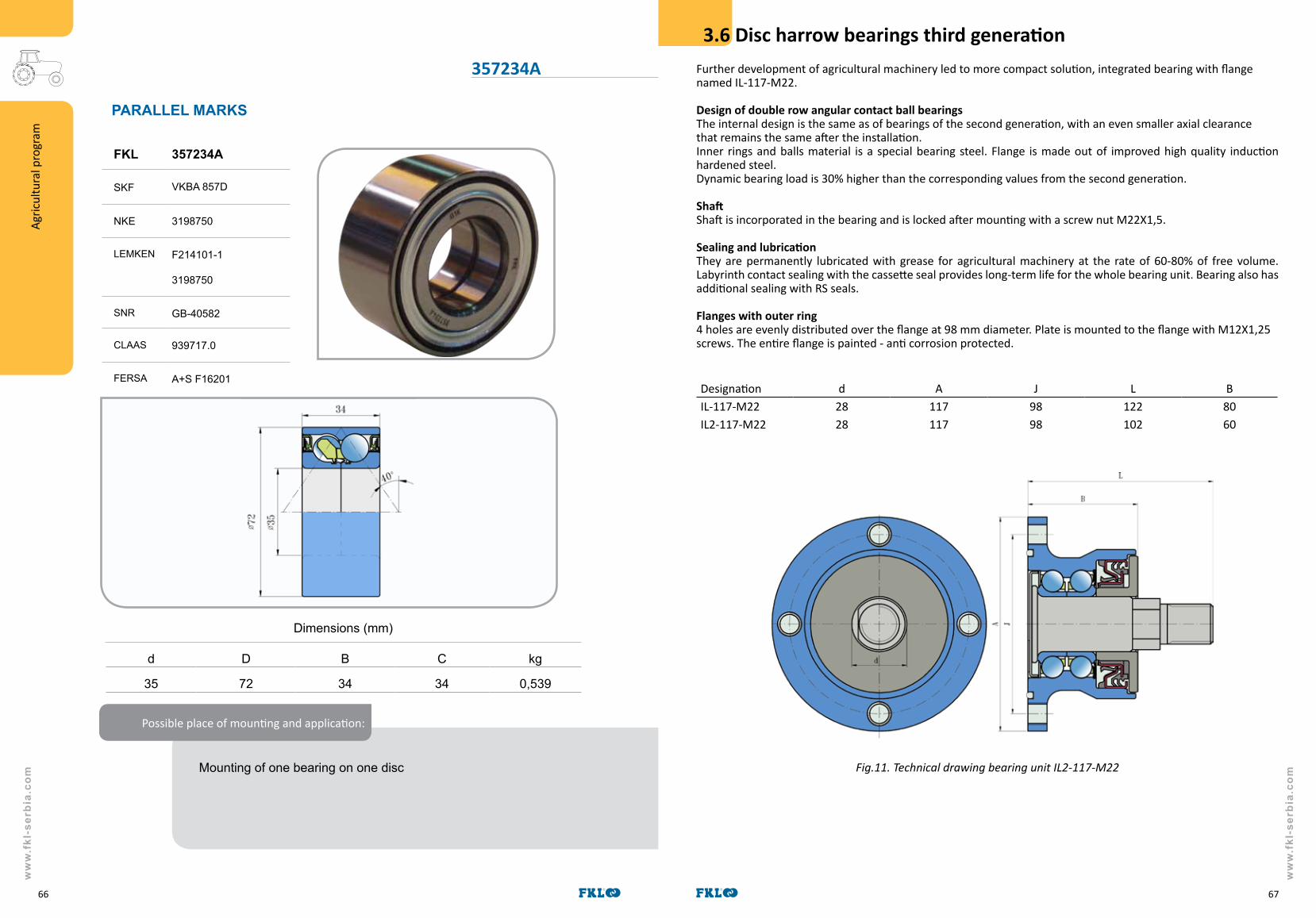
ww
w.f
kl-s
erbi
a.co
m
ww
w.f
kl-s
erbi
a.co
m
6766
Dimensions (mm)
d D B C kg
35 72 34 34 0,539
Possible place of mounting and application:
Mounting of one bearing on one disc
PARALLEL MARKS
FKL 357234A
SKF VKBA 857D
NKE 3198750
LEMKEN F214101-1 3198750
SNR GB-40582
CLAAS 939717.0
FERSA A+S F16201
Agric
ultu
ral p
rogr
am
357234A Further development of agricultural machinery led to more compact solution, integrated bearing with flange named IL-117-M22.
Design of double row angular contact ball bearings The internal design is the same as of bearings of the second generation, with an even smaller axial clearance that remains the same after the installation.Inner rings and balls material is a special bearing steel. Flange is made out of improved high quality induction hardened steel. Dynamic bearing load is 30% higher than the corresponding values from the second generation.
ShaftShaft is incorporated in the bearing and is locked after mounting with a screw nut M22X1,5.
Sealing and lubrication They are permanently lubricated with grease for agricultural machinery at the rate of 60-80% of free volume.Labyrinth contact sealing with the cassette seal provides long-term life for the whole bearing unit. Bearing also has additional sealing with RS seals.
Flanges with outer ring4 holes are evenly distributed over the flange at 98 mm diameter. Plate is mounted to the flange with M12X1,25 screws. The entire flange is painted - anti corrosion protected.
Designation d A J L BIL-117-M22 28 117 98 122 80IL2-117-M22 28 117 98 102 60
Fig.11. Technical drawing bearing unit IL2-117-M22
3.6 Disc harrow bearings third generation
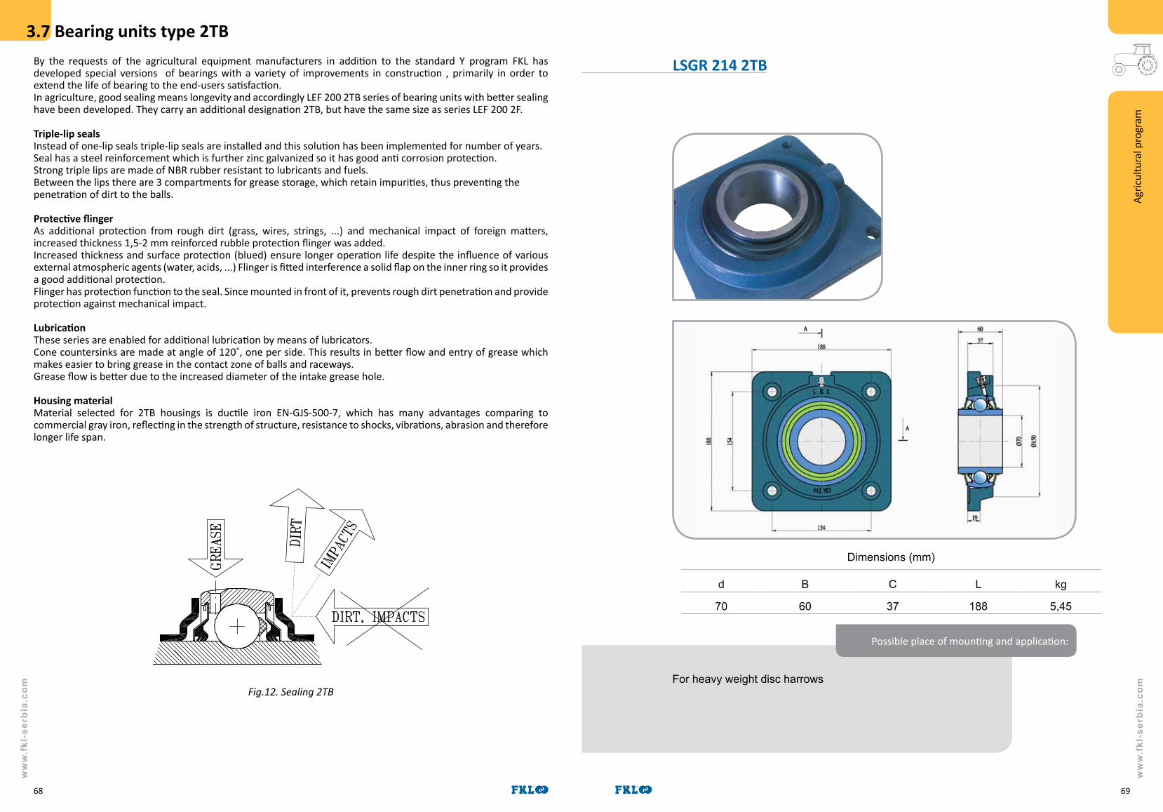
ww
w.f
kl-s
erbi
a.co
m
ww
w.f
kl-s
erbi
a.co
m
6968
By the requests of the agricultural equipment manufacturers in addition to the standard Y program FKL has developed special versions of bearings with a variety of improvements in construction , primarily in order to extend the life of bearing to the end-users satisfaction. In agriculture, good sealing means longevity and accordingly LEF 200 2TB series of bearing units with better sealing have been developed. They carry an additional designation 2TB, but have the same size as series LEF 200 2F.
Triple-lip seals Instead of one-lip seals triple-lip seals are installed and this solution has been implemented for number of years. Seal has a steel reinforcement which is further zinc galvanized so it has good anti corrosion protection. Strong triple lips are made of NBR rubber resistant to lubricants and fuels.Between the lips there are 3 compartments for grease storage, which retain impurities, thus preventing the penetration of dirt to the balls.
Protective flinger As additional protection from rough dirt (grass, wires, strings, ...) and mechanical impact of foreign matters, increased thickness 1,5-2 mm reinforced rubble protection flinger was added.Increased thickness and surface protection (blued) ensure longer operation life despite the influence of various external atmospheric agents (water, acids, ...) Flinger is fitted interference a solid flap on the inner ring so it provides a good additional protection.Flinger has protection function to the seal. Since mounted in front of it, prevents rough dirt penetration and provide protection against mechanical impact.
Lubrication These series are enabled for additional lubrication by means of lubricators. Cone countersinks are made at angle of 120˚, one per side. This results in better flow and entry of grease which makes easier to bring grease in the contact zone of balls and raceways.Grease flow is better due to the increased diameter of the intake grease hole.
Housing materialMaterial selected for 2TB housings is ductile iron EN-GJS-500-7, which has many advantages comparing to commercial gray iron, reflecting in the strength of structure, resistance to shocks, vibrations, abrasion and therefore longer life span.
Fig.12. Sealing 2TB
3.7 Bearing units type 2TB
For heavy weight disc harrows
Dimensions (mm)
d B C L kg
70 60 37 188 5,45
Possible place of mounting and application:
Agric
ultu
ral p
rogr
am
LSGR 214 2TB

ww
w.f
kl-s
erbi
a.co
m
ww
w.f
kl-s
erbi
a.co
m
7170
FKL has developed another series of bearing units for agriculture named LEF 200 2TC. Bearing units for disc harrows, rollers and similar reduced tillage machines, where the grass is present in excessive amounts and high probability for the machine to encounter problems with leftover ropes or winded wires on rotating shaft which tend to destroy the sealing (and a whole bearing) are developed using tin caps protection 2TC.
Five lip seal Instead triple-lips seals, they are incorporated with newly developed seal, five lip seal. Seal has a steel reinforcement which is zinc galvanized and has good corrosion protection.Five strong lips are made out of new type NBR rubber, resistant to oils and fuels, and resistant to high temperatures above 110˚C.
CapAs additional protection from rough dirt (grass, wire, soil, mud ...) and mechanical impact of foreign matter e.g. rubble, protective sheet of the series 2TB, has been replaced with an increased thickness steel cap (1,5-2 mm), that covers the whole front of the bearing unit.Increased thickness and surface protection improves longer operation life. The tin is mounted below the cast housing tightening screw.It also has protective function for the five-lips seal , because it is mounted in front of the seal and prevents penetration of rough dirt to the seal and protects it from mechanical impact.
Lubrication These series are enabled for additional lubrication by means of lubricators. Cone countersinks are made at angle of 120˚, one per side. This results in a better flow and entry of grease which makes easier to bring grease in the contact zone of balls and raceways.Grease flow is better due to the increased diameter of the intake grease hole and number of holes is increased from 2 to 3.
Housing materialMaterial selected for 2TC housings is ductile iron EN-GJS-500-7, which has many advantages comparing to commercial gray iron, reflecting in the strength of structure, resistance to shocks, vibrations, abrasion and therefore longer life span. Color of these housings is black.
Anti-corrosion protection of the inner ringInner rings are galvanized to prevent the occurrence of corrosion which also extends the lifetime of seal lips.
Fig.13. Bearing units type 2TC
3.8 Bearing units type 2TC 3.9 Special bearings
06C04-2Z AA21480; 204RY2(204JY3); 822-011C; 820-033C
204 KRR2JD7126; AH107148; JD7126; 822-173С; 1AH01-11/16
209 KRR K/50.135straw walker shaft for CLAAS
203 KRR.AH02AN100425; JD 9214; 666624R91; F16246
204 KRRB2A-HPS011GP11K204N
210 RRB6AE42880 ; HPS108GPB-I;
203 KRR.AH05 JD10008; 611928R91; 3198563
205 KRP2 40-155; A27002; 1337998C1
3204 B.2RS1 for Majevica-Serbia machines
FKL developed a range of special bearings according to customer request that are broadly used in agricultural machinery. Here is a brief survey of some versions which were developed in last two years.

ww
w.f
kl-s
erbi
a.co
m
ww
w.f
kl-s
erbi
a.co
m
7372
3.9 Special bearings
GW 211PP2028К2050 (SUMMERS);8K2000 (SUMMERS)
GWR 209PPB30GW209PPB23+BR209RH;40-167; CDS209TTR6PA
GWST 211PPB20AA 30941 822-208С
60Z45for tractors DEUTZ, FENDT
GWHR 211PP2028К2050 (SUMMERS);8K2000 (SUMMERS)
GWR 211PPB21822-026; CDS211TTR23N/3A; GW211B21+BR211RH
IL-117-M22 (“SKF” BAA-OO4) for disc harrows
885152AA21015-AA35741;128558C91; A2022
885154BAN 131668; 446612MI
GWHG 211PP25SN3090; SN3091; SN 1937
GWST 209PPB13AA30941; AA29784; AA28184
5206KPP3822-215C; GA8603, GA8641
LSNR 207-TBS3199352;F-232812-0200
LSGR 205-FS3199371; F-239975
SL 5203-2T822-170C; 324461A1; N212132; GA6171; AN212132; Y00513900
SL 53-014 2Т188-006V
LSGR 207 2TB3199372; F-232812
SBX 1227409556A1
SL 5316-2T AA205DD; 188-001V; 205VVH-I
SLE 53-012-2T 188-009V
LSNR 205-2T3199367;F-233449
ILSGE 213 for AMAZONE machines
SL 3303 2S for Seeding machines (ТСМ - 8000, ТСМ - 8000А, ТСМ - 4150)
SLU 53-012-2T188-004V

ww
w.f
kl-s
erbi
a.co
m
ww
w.f
kl-s
erbi
a.co
m
7574
SizeUniversal joint
dimensionsDinamic capacity
Md (Nm)
ØA (mm) B(mm) 540 min-1 1000 min-1
05 22 55 210 172
08 24 61 270 220
12 27 75 460 380
16 32 76 620 520
18 34 90 830 710
20 35 106.5 1240 1050
Size 05 08 12 16 18 20
Lmin 460 465 480 505 515 545
L 90 98 107 112 116 129
Lmax 1950 2000 2000 2000 2000 2000
L1min L1min = Lmin + L + L
Lmin - minimal shaft lenght (compressed) Lmax - maximal shaft lenght in operation
4. PROGRAM OF CARDAN SHAFTS
Outer yokes DSize
05 08 12 16 18 206x21x25 (6) × ×6x26x30 (6) × ×6x32x38 (8) × × × ×Tip1 1⅜" (6) × × × ×
Tip2 1⅜" (21) × × × ×6x32x38 (8) × ×Tip1 1⅜" (6) × ×
Tip2 1⅜" (21) × ×Tip3 1¾" (20) ×
1¾" (6) ×6x23x28 (6) × ×6x26x30 (6) × ×Tip1 1⅜" (6) × × × × × ×
Tip2 1⅜" (21) × × × × ×1¾" (6) ×20H8 ×25H8 × ×30H8 × × × × ×35H8 × × × × ×40H8 × × ×20H8 ×22H8 ×25H8 × × ×30H8 × × × × ×35H8 × × × ×40H8 × × × ×
Tip1 1⅜" (6) × × × × ×1¾" (6) × ×
Tip3 1¾" (20) ×
20H8 ×22H8 ×25H8 × × × ×30H8 × × × × ×35H8 × × × ×40H8 × × × ×
75 ×87.5 ×90 × ×
100 × × ×120 × ×
4.2 Table of drive shaft yokes
4.1 Cardan shafts

ww
w.f
kl-s
erbi
a.co
m
ww
w.f
kl-s
erbi
a.co
m
7776
Different driving requirements of agricultural machines, first of all large kinetic energy of the driving machines flywheels require the insurance of working and driving elements by means of safety couplings. Couplings for cardan shafts preserve the driving system from the overload moment effect and in that way provide optimal utilization of material with construction of structures as well as the safe and uninterrupted machine operation. The couplings are of simple construction, they are easy to maintain and made of high quality local materials. The criteria for the couplings choice per size and working manner are the types of machines and type of load. Tolerances for fitness of coupling load compared to the declared capacity is ± 10%.
OVERRUNNING CLUTCHES
are applied as balance clutches in cases when there is a danger of flywheel moment effect of the working machine to the driving elements in case of driving machine suddenly stops working.
RADIAL PIN CLUTCHES
with radial hinges by means that hinge shape closes the power flow when overloaded hinges are pushed to the holes and then sliding occurs between the drive and driven part of the coupling in the pulsating manner. The sharp sound which appears than has a warning role.
SHEAR BOLT CLUTCHES
are rough couplings and are used to avoid blockage due to overload. The increase of moment beyond the shearing screw causes the screw shearing and the flow of power is interrupted. By the screw replacement the power transmission is set again.
FRICTION CLUTCHES
are safety couplings which by means of splitting power transmits the turning moment. These are used with the drive where the overloads are frequent and short. Here the interruption and reestablishment is softer then with the safety couplings with radial hinges.
FRICTION AND OVERRUNNING CLUTCHES
present the combination of one-way and friction couplings so the type of operation is determined according to the characteristics set above.
4.3 Overload and overrunning clutches
SJ
OVERRUNNIG CLUTCHES Type Capacity(Nm)
Dimensions (mm) PTO Drive shafts
B A D C 05 08 12 16 18 20
SJ-2 1600 131 24 100 × × ×
SJ-2V 1600 131 24 100 38
SJ-4 2400 143 24 100 × ×
SJ-4V 2400 151 24 100 38
51.AM 3000 141 37 73 28
Connections: Shaft 1⅜"; Hub 1⅜"; 1⅛"
SRRADIAL PIN CLUTCHES Type Capacity
(Nm)Dimensions (mm) PTO Drive shafts
B A D C 05 08 12 16 18 20SR-1 300 127 24 100 × ×
SR-2 600 153 24 100 × × ×
SR-3 900 176 24 100 × × ×
SR-4 1200 203 24 100 ×
SR-1V 300 119 24 100 38
SR-2V 600 151 24 100 38
SR-3V 900 171 24 100 38
SR-4V 1200 191 24 100 38
Connections: Shaft 1⅜"; Hub 1⅜"; 1⅛"
SV
SHEAR BOLT CLUTCHES Type Capacity(Nm)
Dimensions (mm) PTO Drive shafts
B A R2 R1 05 08 12 16 18 20 8.8
SV-05 320 95 20 35 55 × M6x40
SV-08 450 99 20 45 55 × M6x40
SV-12 740 107 20 48 63 × M8x45
SV-16 1350 109 21 55 63 × M8x45
SV-18 1600 137 24 60 78 × M8x55
SV-20 2000 143 24 45 78 × M10x60
Connections: Hub 1⅜"; 1¾"
SF
FRICTION CLUTCHES Type Capacity(Nm)
Dimensions (mm) PTO Drive shafts
B A D C 05 08 12 16 18 20SF-1 900 138 24 170 × ×
SF-2 1200 147 24 170 × × ×
SF-3 1500 170 24 190 × ×
SF-4 2000 170 24 210 ×
SF-1V 900 143 24 170 38
SF-2V 1200 143 24 170 38
SF-3V 1500 162 24 190 38
SF-4V 2000 162 24 210 38
Connections: Shaft 1⅜"; Hub 1⅜"; 1⅛"
SFT
FRICTION CLUTCHES Type Capacity(Nm)
Dimensions (mm) PTO Drive shafts
B A D C 05 08 12 16 18 20
SFT-1 300-700 154 24 168 × ×
SFT-2 700-1400 176 24 168 × × × ×
SFT-1V 300-700 148 24 168 38
SFT-2V 700-1400 160 24 168 38
Connections: Shaft 1⅜"; Hub 1⅜"; 1⅛"
SJF
FRICTION AND OVERRUNNING CLUTCHES Type Capacity(Nm)
Dimensions (mm) PTO Drive shafts
D B C 05 08 12 16 18 20
SJF-1V 800 230 158 38 × × × ×
Connections: Shaft 1⅜"; Hub 1⅜"; 1⅛"
Overload and overrunning clutches

ww
w.f
kl-s
erbi
a.co
m
ww
w.f
kl-s
erbi
a.co
m
7978
FKL Temerin is a producer of rolling bearings and cardan shafts. The company was established in 1961, located at the area covering 13 hectares. Production area consists of two plants, covering 25 000 m2.
OUR qUALITY HAS BEEN BUILT ON:
qMS verifed by ISO 9001, ISO 14001 and ISO 18001
High quality raw material
Own R&D department
Highly productive and modernized equipment
qualified personnel
FKL PRODUCTS COMPLY TO RUSSIAN MARKET STANDARDS
FKL POSSESS OWN ACCREDITED LABORATORY FOR PRODUCT TESTING
5. OTHER INFORMATION

Y INSERT BEARINGS AND BEARING UNITS
DEEP GROOVE BALL BEARINGS
CILYNDRICAL ROLLER BEARINGS
DOUBLE ROW SPHERICAL
ROLLER BEARINGS
NEEDLE ROLLER BEARINGS AND BALL BEARINGS FOR
AGRICULTURAL MACHINES
CLUTCH BEARINGS
BALL BEARINGS FOR AUTOMOTIVE
INDUSTRY
CARDAN SHAFTS FOR MOTOR VEHICLES
CARDAN SHAFTS FOR AGRICULTURE
CARDAN SHAFTS FOR INDUSTRY
OVERLOAD AND OVERRUNNING CLUTCHES
Factory of Rolling Bearings and Cardan Shafts FKLIndustrijska zona bb21235 TemerinSERBIA
Phone: +381 21 6841 100Fax: +381 21 842 650, 843 282E-mail: [email protected]: www.fkl-serbia.com
ww
w.f
kl-s
erbi
a.co
m
81
ww
w.f
kl-s
erbi
a.co
m
80
BRANCH OFFICE:
LLC “FKL-RUSSIA” Novgorodskaya Str. 121
394088 VORONEZHRUSSIA FEDERATION
Phone/Fax: +74732 747150 / 748361E-mail: [email protected]
Web: www.rusfkl.ru
P R O D U C T I O N P R O G R A M M E


