Download - Advances in iol calculation
M. Khanlari , MD
ADVANCES IN IOL CALCULATION
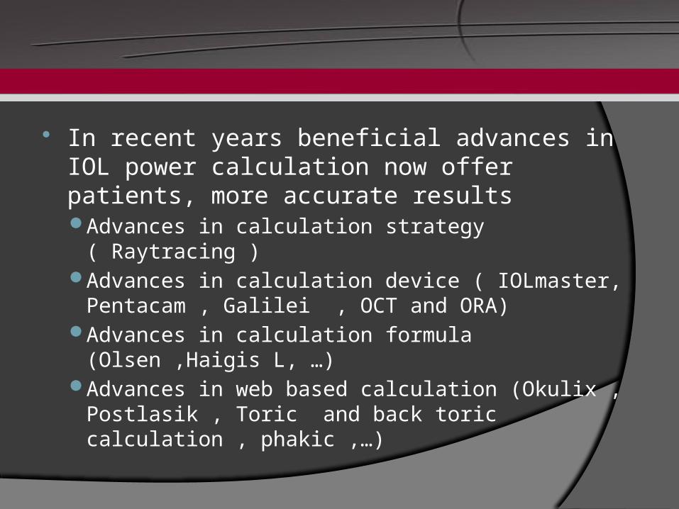
In recent years beneficial advances in IOL power calculation now offer patients, more accurate resultsAdvances in calculation strategy ( Raytracing )Advances in calculation device ( IOLmaster, Pentacam
, Galilei , OCT and ORA)Advances in calculation formula (Olsen ,Haigis L, …)Advances in web based calculation (Okulix ,
Postlasik , Toric and back toric calculation , phakic ,…)
Demand for a Different Strategy
Karl Friedrich Gauss developed a calculation method utilizing Snell’s law in a simplified version that can be calculated in closed formulae such as the well-known IOL formulae.
Gaussian optics is only valid in optical systems centered relative to an optical axis.
In addition, the rays of interest must have only very small angles relative to the optical axis.
Gaussian optics limitations“thin lens” assumption
The currently used 3rd-generation IOL
calculation formulae do not even utilize the full capabilities of Gaussian optics. Instead, they apply two additional simplifications: anterior and posterior corneal surface are combined to
one surfacethe IOL is approximated as a “thin lens”.
Gaussian optics limitations “e ective lens position”ff
The second di erence between the formulae is the ffassumed position of the IOL. If the so-called “formula constants” are adjusted correctly, this position is the position of a thin lens of the appropriate power which gives the eye the required target refraction.
This fictitious position is often called “e ective lens ffposition” (ELP). As a consequence of di erent corneal ffrefractive indices for the di erent formulae, the ELPs ffmust di er too. Thus, the di erent formulae in fact ff ffdescribe di erent physical systems. ff
Gaussian optics limitations“corneal refractive index”
The combination of anterior and posterior corneal surface to one surface needs assumptions about the ratio of anterior and posterior curvature radii.
For a given ratio a fictitious “corneal refractive index” is calculated which is smaller than the refractive index of the corneal material and smaller than the refractive index of aqueous humor, because the posterior cornea acts as a minus lens.
Di erences in this fictitious corneal refractive index is ffone of the di erences between the IOL formulae.ff
Demand for raytracing The visual impression of an object can be simulated by
the superposition of many rays. Diffraction from the pupil aperture is taken into account
additionally. For a single ray passing multiple surfaces the calculation
cannot be performed by analytical formulae, because otherways so-called “transcendental equations” occur which are unsolvable for principal mathematical reasons.
Instead of an analytical calculation (closed formula) the problem therefore has to be solved by numerical methods.
Raytracing as a different strategy
Raytracing is defined as a calculation method for single rays passing through an optical system. Starting at a given point and at a given angle relative to the optical system according to Snell’s law
Raytracing solutions
Raytracing applied to IOL calculation utilizes a description of the pseudophakic eye in which anterior and posterior corneal surface ideally should be topographically measured.
The IOL is described by anterior and posterior central curvature radius, asphericity (if any) of the surfaces, central thickness and index of refraction.
The position of this IOL is the true geometrical position, e.g. defined by the anterior chamber depth (ACD), the distance between posterior corneal and anterior IOL apex.
Raytracing vs Gaussian opticspostoperative IOL position determination
With respect to the prediction accuracy of postoperative IOL position, there is no principal advantage of raytracing compared to calculations in Gaussian optics.
But any prediction method for postoperative ACD used in raytracing can be directly compared to corresponding ACD measurements.With the fictitious ELP of the IOL formulae such a direct comparison is not possible.
ACD measurements can be performed by partial coherence interferometry (PCI) with high accuracy
Okulix as a raytracer calculator OKULIX, a new biometric computer program to stimulate the
whole pseudophakic eye, aims to reduce calculation error and ensure a more reliable estimation of IOL strength
overcomes the limitations of Gaussian optics by using numerical ray-tracing.
proposes the ACD by recalculating it from A-constants using numerical methods
will only perform well with exact measurements of axial length, corneal power and a good estimation of the postoperative IOL position.
With the introduction of the IOL Master together with ray-tracing for IOL power calculation, we have powerful tools to significantly improve refractive outcome after cataract surgery.
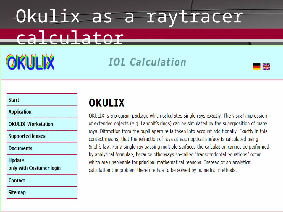
Okulix as a raytracer calculator
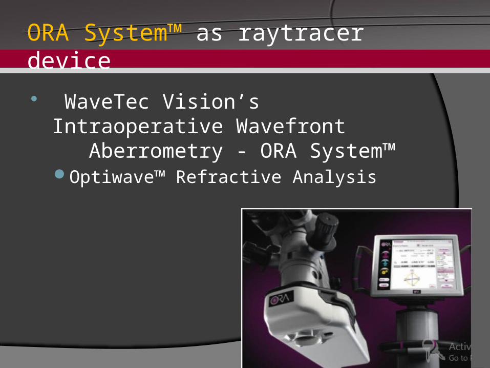
ORA System™ as raytracer device
WaveTec Vision’s Intraoperative Wavefront Aberrometry - ORA System™ Optiwave™ Refractive Analysis
ORA System™ Optiwave™ Refractive Analysis
Developed and manufactured by WaveTec Vision, Aliso Viejo, CA Intraoperative wavefront aberrometerFits on the bottom of surgical microscopeImproves accuracy in IOL power calculations
Including post-refractive surgery patients Assist in more precise toric IOL placement and
cylinder power selection Provides consistency in LRI procedures Excellent synergy with Femtosecond laser technolog
Demand for a different formula Two major error in IOL Calculation
Error in measurment (keratometry,Axial length)○ Can be decreased by laser interferometry
Error in formula (corneal power , ELP)○ Different formula ,different approach for
prediction of ELP
Olsen formula And C Constant Laser optical biometry measures both pre (based
on preop ACD and LT ) and postop ELP ( based on C constant )
C constant defines the final position of the IOL as a function of capsular bag size and preop ELP
The mean absolute error was reduced by 14% as compared to SRK T formula
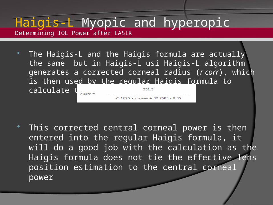
Haigis-L Myopic and hyperopicDetermining IOL Power after LASIK
The Haigis-L and the Haigis formula are actually the same but in Haigis-L usi Haigis-L algorithm generates a corrected corneal radius (r corr), which is then used by the regular Haigis formula to calculate the IOL power
This corrected central corneal power is then entered into the regular Haigis formula, it will do a good job with the calculation as the Haigis formula does not tie the effective lens position estimation to the central corneal power
Demand for new devices Pitfalls of keratometry in special
conditions(postlasik ,post pk ,….cornea)Pentacam (EKR)Topography(Holladay Report, …)IOLmaster (Hagis-L)Lenstar and BiographGallilei (TCP)
Pitfalls of AL measurmentIOLmaster ,Lenstar and Biograph
Piffalls of ELP detectionRaytracingOCT
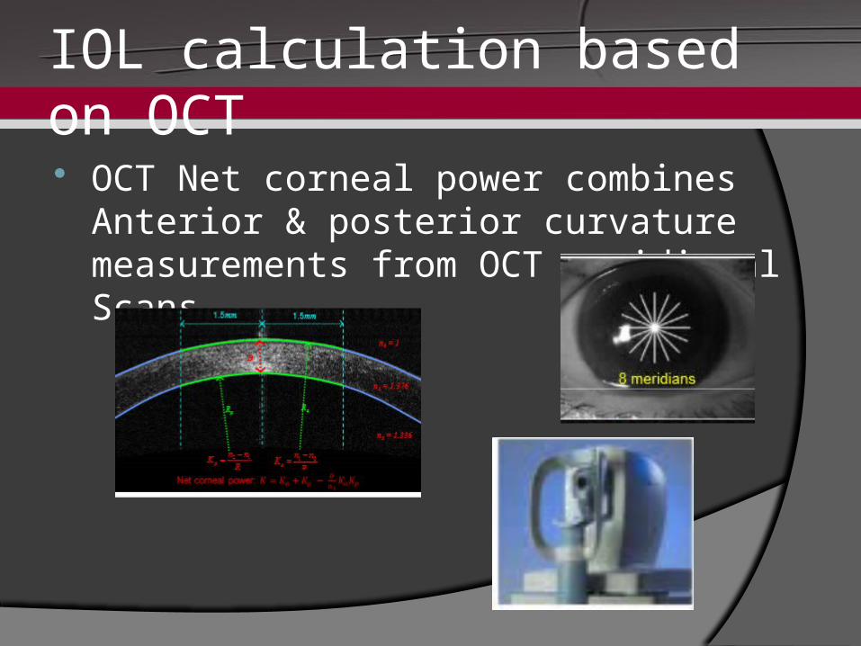
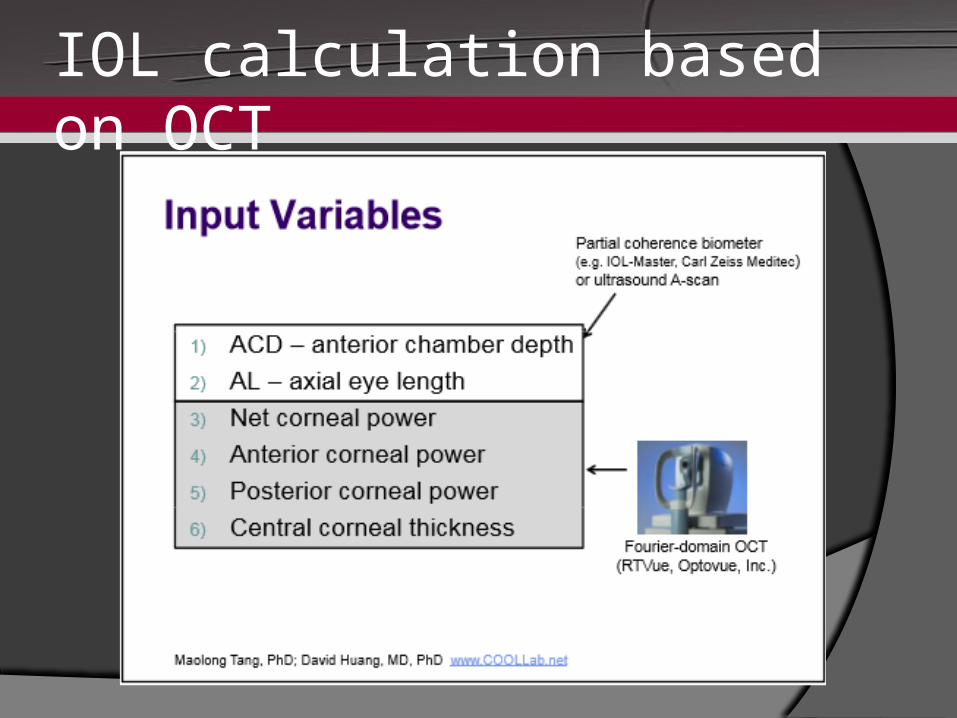
IOL calculation based on OCT OCT Net corneal power combines Anterior &
posterior curvature measurements from OCT meridional Scans
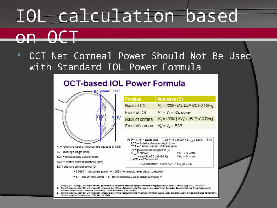
IOL calculation based on OCT OCT Net Corneal Power Should Not Be Used with
Standard IOL Power Formula
IOL calculation based on OCT
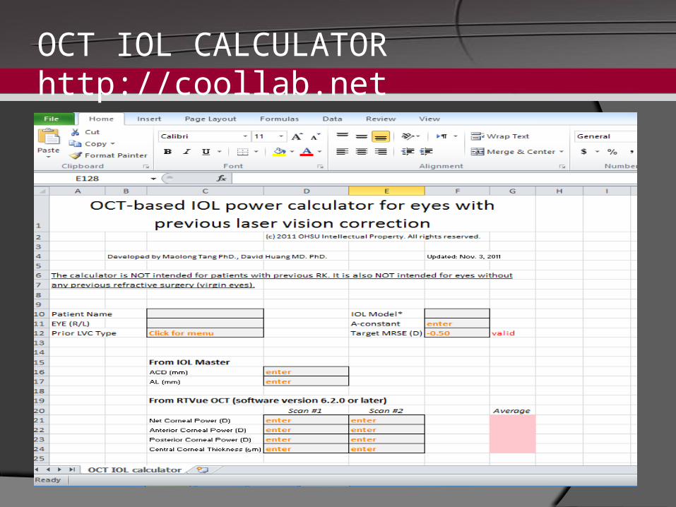
OCT IOL CALCULATORhttp://coollab.net
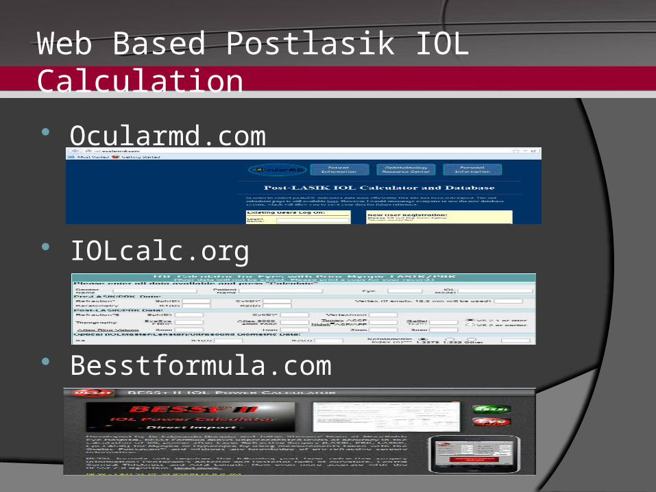
Web Based Postlasik IOL Calculation
Ocularmd.com
IOLcalc.org
Besstformula.com
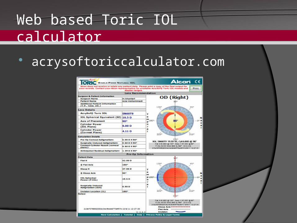
Web based Toric IOL calculator
acrysoftoriccalculator.com
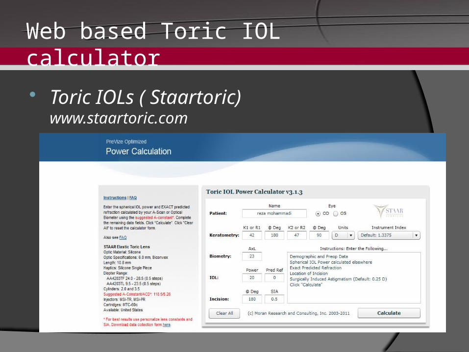
Web based Toric IOL calculator
Toric IOLs ( Staartoric)www.staartoric.com
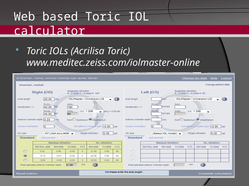
Web based Toric IOL calculator
Toric IOLs (Acrilisa Toric)www.meditec.zeiss.com/iolmaster-online
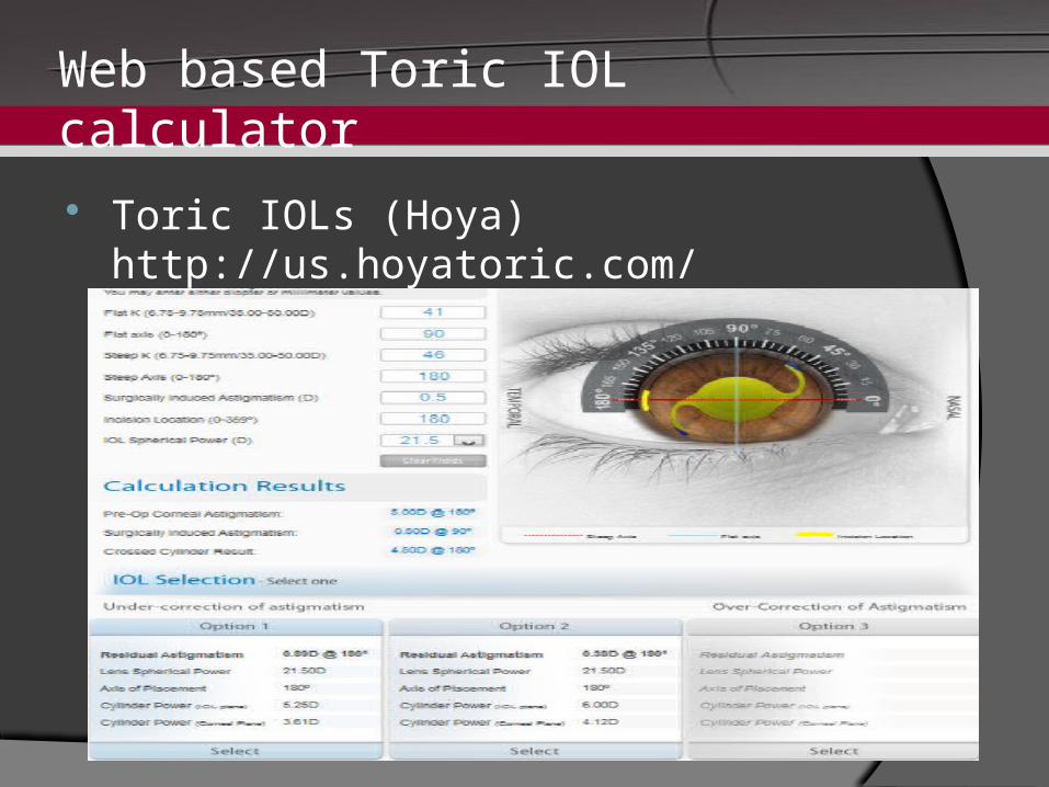
Web based Toric IOL calculator
Toric IOLs (Hoya)http://us.hoyatoric.com/
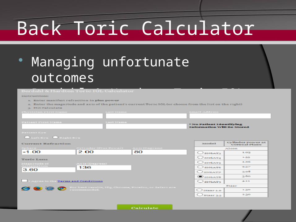
Back Toric Calculator Managing unfortunate outcomes
Berdahl & Hardten Toric IOL Calculator
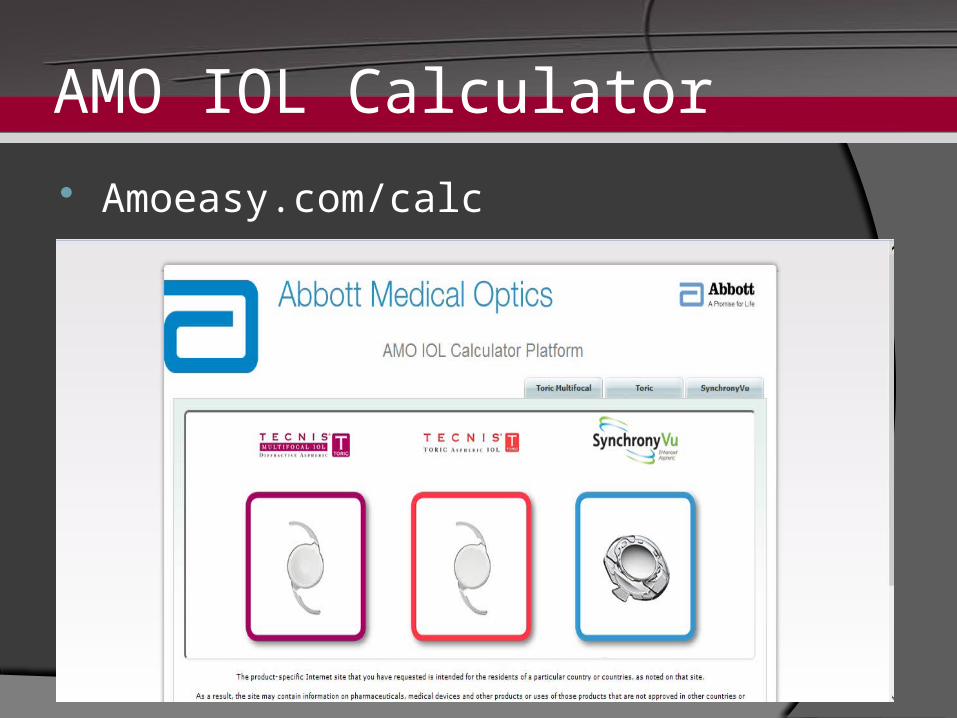
AMO IOL Calculator Amoeasy.com/calc


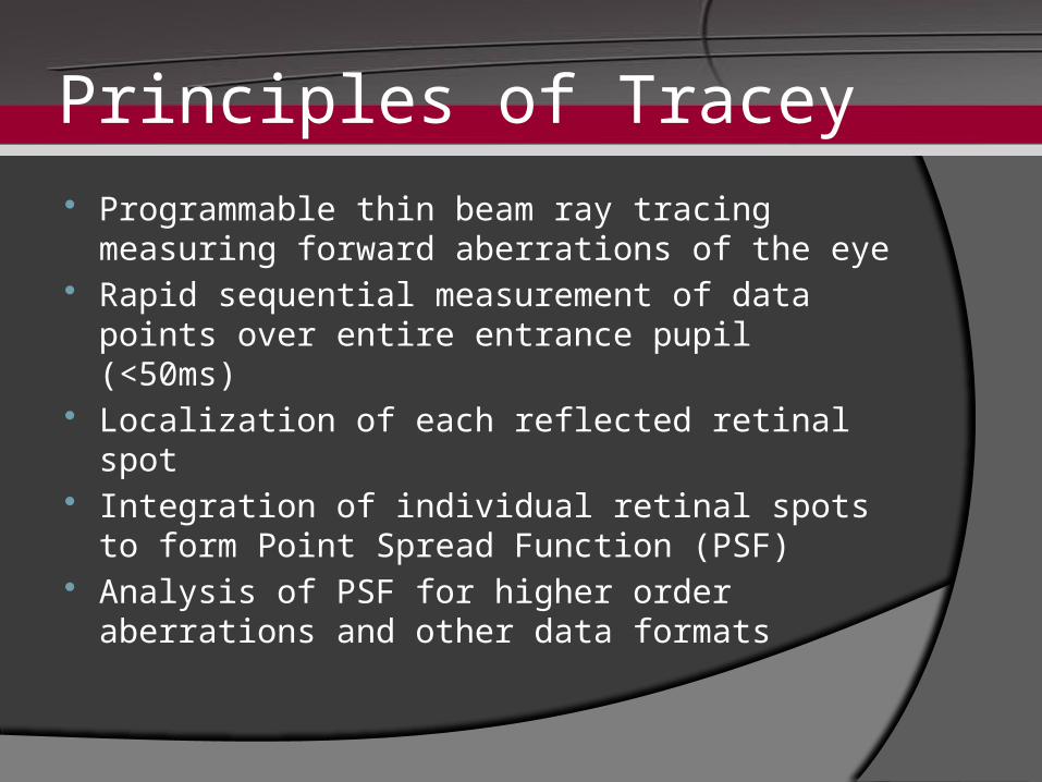
Principles of Tracey Programmable thin beam ray tracing
measuring forward aberrations of the eye Rapid sequential measurement of data
points over entire entrance pupil (<50ms) Localization of each reflected retinal spot Integration of individual retinal spots to
form Point Spread Function (PSF) Analysis of PSF for higher order
aberrations and other data formats
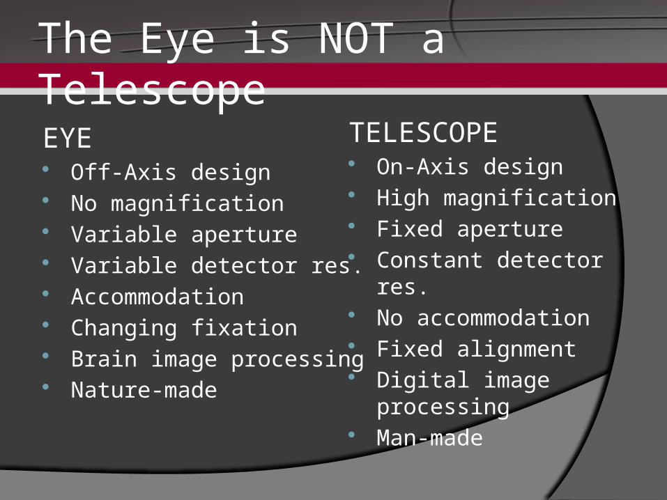
The Eye is NOT a Telescope
EYE Off-Axis design No magnification Variable aperture Variable detector res. Accommodation Changing fixation Brain image processing Nature-made
TELESCOPE On-Axis design High magnification Fixed aperture Constant detector res. No accommodation Fixed alignment Digital image processing Man-made
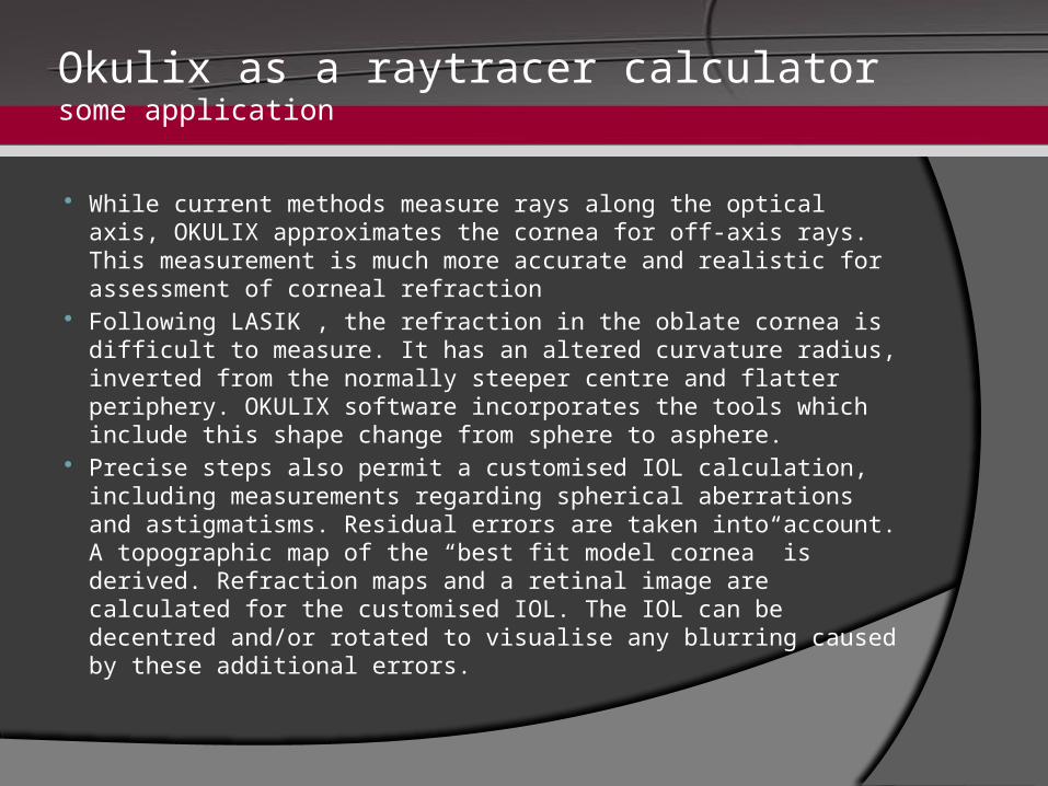
Okulix as a raytracer calculatorsome application
While current methods measure rays along the optical axis, OKULIX approximates the cornea for off-axis rays. This measurement is much more accurate and realistic for assessment of corneal refraction
Following LASIK , the refraction in the oblate cornea is difficult to measure. It has an altered curvature radius, inverted from the normally steeper centre and flatter periphery. OKULIX software incorporates the tools which include this shape change from sphere to asphere.
Precise steps also permit a customised IOL calculation, including measurements regarding spherical aberrations and astigmatisms. Residual errors are taken into account. A topographic map of the “best fit model cornea” is derived. Refraction maps and a retinal image are calculated for the customised IOL. The IOL can be decentred and/or rotated to visualise any blurring caused by these additional errors.

![The Accuracy of Intraocular Lens Power Calculation Formulas for … · 2019-11-05 · results in IOL power calculation for eyeballs with AL smaller than 22.0mm [3,5-8]. Similar conclusions](https://cdn.vdocuments.us/doc/165x107/5fba3ed36e7f08078a0aef80/the-accuracy-of-intraocular-lens-power-calculation-formulas-for-2019-11-05-results.jpg)


