
UNCLASSIFIED
AD 296875
ARMED SERVICES TECHNICAL INFORMATION AGENCYARLINGTON HALL STATIONARLINGTON 12, VIRGINIA
UNCLASSIFIED

NOTICE: When goverment or other drawings, speci-fications or other data are used for any purposeother than in connection with a definitely relatedgovernment procurement operation, the U. S.Government thereby incurs no responsibility, nor anyobligation whatsoever; and the fact that the Govern-ment may have formulated, furnished, or in any waysupplied the said drawings. specifications, or otherdata is not to be regarded by implication or other-wise as in any manner licensing the holder or anyother person or corporation. or conveying any rightsor permission to manufacture, use or sell anypatented invention that may in any way be relatedthereto.

296 875IThree-Level Maser Materials: ASurvey of Potential Materials, I
SbyJ. Wakabayashi
Series No. 60, Issue No. 439Contract No. AF 49(638)-102March 7, 1962

"Qualified requestors may obtaincopies of this report from ASTIA"

Electronics Research LaboratoryUniversity of CaliforniaBerkeley, California
THREE-LEVEL MASER MATERIALS: A SURVEY OF POTENTIALMATERIALS, I
by
J. Wakabayashi
Institute of Engineering ResearchSeries No. 60, Issue No. 439
Physics DivisionAir Force Office of Scientific ResearchContract No. AF 49(638)-102Division File No. 13-25-J
March 7, 1962

ACKNOWLEDGMENTS
I wish to thank my research advisor, Professor
J. R. Singer, for his constant support and encouragement during
the course of this research.
I also wish to acknowledge my debt to A. Yariv for
initiating the research in the maser field and establishing the
laboratory facilities which were used in this work.
I am indebted to Dr. J. C. Kemp for perfecting
the equipment and the experimental techniques which were passed
on to me.
I wish to thank Professor R. J. Myers of the
College of Chemistry, Professors H. A. Jeffries, A. M. Portis
and M. Tinkham of the Department of Physics, Professor A. Pabst
of the Department of Geology, Drs. R. J. Elliot and B. Bleaney
of Oxford Universityand Dr. J. C. Kemp for frequent and helpful
discussions of the problems encountered in this research.
I also wish to thank F. D. Clapp for his inval-
uable help in all phases of microwave technique and F. Koch
and A. Hiiger of the Department of Physics for the use of their
spectrometers.
Finally, I wish to thank the United States Air Force
and the staff of the Electronics Research Laboratory for their
sponsorship of this work through many unproductive quarters.
-1i

TABLE OF CONTENTS
CHAPTER I INTRODUCTION......................1I
CHAPTER II PARAMAGNETIC RESONANCE IN CRYSTALS:
A REVIEW.......................... 6
11. 1 The Hamiltonian for a Paranmagnetic
Ion in a Crystal.................. 7
11. 2 The Configuration................. 9
11. 3 The Term...................... 11
11.4 The Effect of the Crystalline Field on
the Orbital State.. .. .. .... ..... 13
UI. 5 The Effect of Spin-Orbit and Zeeman
Energies, The Case of the Non-Degene-
rate Ground Orbital State .. .. .. .... 16
11.6 Zero-Field Splitting. .. .... ..... 21
11.7 The Zeeman Energy. .. .... ..... 23
11.8 Hyperfine Structure. .. .. .... .... 25
11. 9 The Case of the Degenerate Orbital
Ground State .. .. ...... ...... 26
II-10 Other Methods for the Analysis of
Paramagnetic Ions .. .. ..... .... 29
11. 11 Koster's Method .. .. ...... .... 31
11.12 The Theory of T . . . . . . . . . . . 32
CHAPTER III THE RELATIONSHIP BETWEEN THE MATER-
IAL PARAMETERS AND MASER PERFORM-
ANCE. .. ... ...... ..... ...... 35
111. 1 Bloch's Equations. .. .. .... ..... 35
111. 2 The Reflection Cavity Maser. .. .. ... 44
111. 3 Summary. .. ... ...... ...... 55

Page
CHAPTER IV A SURVEY OF POTENTIAL CRYSTALS FOR
THREE-LEVEL MASERS................ 58
IV.l1 The Paramnagnetic Ion............. 58
IV. 2 The Host Crystal .. .. .... ....... 61
IV. 3 Availability of Crystals............ 70
-iv-

CHAPTER I
INTRODUCTION
1In 1956 Townes et al. proposed and successfully produced
an oBcillator which utilized the induced emission from an
excited quantum energy state. It was named the maser. A
brief sketch of its principles is as follows.
Two quantum energy states exist. The difference in their
energies is AE. In the presence of an electromagnetic field, a
system in the lower energy state will absorb energy from the field
at a rate A which is sharply peaked when the incident field is of the
frequency f = ---- where h is Planck'sconstant. This rate is propor-
tional to the square of either the electric or magnetic field strength.
Similarly, a system in the upper energy state emits energy to
the field at the same rate A in the same frequency and direc-
tion as the incident field. If an ensemble is composed of a
mixture of systems in the lower and upper energy states, then
the ensemble's absorption is A(nI-n 2 ), where n 1 is the number of
particles in the lower state and n2 is the number of particles
in the upper energy state.
If we wish to make an amplifier, we must obtain from
such a device a field which is larger than the field which we feed
into the device. In a maser, this means that there should be
a net emission of energy by the system into the field. This
requires that A(nl-n 2 ) must be negative or that n 2 > n1 . If the
device were lossless, we would have an amplifier whenever this
requirement is fulfilled. In practice, A(n1 -n 2 ) must be sufficiently
negative to overcome inevitable losses. For an oscillator,
A(nl-n 2 ) must be negative enough to overcome not only its own
losses but the losses in the load as well.
At thermal equilibrium, the lower energy state is always
more heavily populated than the upper state. The ratio is given
-1-

by Boltzmann's distribution
n 2 -AE/kT7T = eni
Therefore, some process is required to upset this thermal equilibrium
before a maser can be made to operate. This process is called
inversion (because it inverts the population of the states at
thermal equilibrium) or pumping.
In the first maser due to Gordon, Zeiger, and Townes, a
beam of ammonia molecules passed through a multipole electric
field with a gradient which deflects high energy molecules different-
ly from the low energy molecules. Thus, a separation of high and
low energy molecules is achieved. This creates a beam of mole-
cules in which > 1. This beam satisfies the condition for a
maser. This beam is passed on into a cavity which is tuned to the
trans itionfrequency f ="R where h is Planek's constant. If
the Q is high enough to give A (the transition probability) its
proper value, maser oscillation or amplification takes place.
The maser aroused great interest because of two advantages.
(1) As an oscillator it has very great stability.
(2) As an amplifier it has a much lower noise figure than that of
vacuum tubes or transistors.
These advantages were demonstrated by both theory and experi-
ments.
The success of the first maser naturally stimulated vigorous
efforts to improve its characteristics. The ammonia maser had a
low power-handling capacity. One way to overcome this character-
istic is to use a solid as the maser material. The higher density
of active atoms would allow both higher power capacity and com-
pactness. Zeeman levels of paramagnetic ions in solids provide
convenient energy levels for masers in the microwave frequency
range. 4,5

In such a maser, a dielectric solid, containing a small
amount (typically . 05%) of paramagnetic centers, is subject to
a strong d. c. magnetic field. The magnetic moment due to
electron spin interacts with the magnetic field to give an
energy gpl!. 19. , where g and A are constants, T1 is the d. c.
magnetic field, and ' is the electron spin. Discrete quantum
energy levels result from the discrete quantum orientations
of' -with respect to H Such levels can be inverted by several
methods developed in the study of nuclear magnetism. Examples
are adiabatic fast passage (AFP), 1800 pulse inversion or d. c.
field reversal.
These masers can generate a moderate amount of peak
power but have the serious drawback that they can only be
operated as pulsed devices. This is because the inversion process
and maser process can never be simultaneous. First, an inver-
sion process is applied. When this process is over, the maser
process takes over. The maser process can last only as long as
the state of inversion exists. As the maser process proceeds,
inversion is reduced until the maser process is no longer possible.
The system must then be allowed to relax to thermal equilibrium
before the inversion process is applied again. Because of this
limitation, the two-level solid state maser is considered now
only as a measure to reach the millimeter wave region by pulsed
d. c. magnetic fields. 2, 34
In 1957 Bloembergen proposed a new type of maser which
could be operated continuously. Briefly, the principle was as
follows.
An atom has three quantum energy states with energies
Ely E2P and E3' respectively. The energy differences are
AE 2 1 , AE 3 2 and AE 3 1 as in Fig. I. At thermal equilibrium,
the probability of occupation of the three levels is given by
Boltzmann's distribution. Each higher level has a smaller
population then its lower neighbor.
-3-

3-
AE 32
E 2 AE 3 1 Figure 1E 2
~E1 3
Now, if a strong electromagnetic field of frequency f=-h is applied
induced transition causes atoms at E1 to be excited to E 3 and atoms at
E 3 to be de-energized to E I. This is called pumping. The induced
transition rates per atom for these two processes are equal for
these equally degenerate states. The net rate is then given by
A(n-n3 ), where A is induced transition rate and n I and n 3 are the
number of units at energy E I and E 3 , respectively. If this rate
A is very much larger than the mechanisms which promote
thermal equilibrium, a steady state is achieved when A(n-n 3 ) = 0.
Therefore, with strong inducing fields, n, = n 3 . This condition
is called saturation. If, furthermore, A is very much larger than
the mechanisms (relaxation) which bring EI and E 3 into thermal
equilibrium with E2 , and these mechanisms are of equal strength
for E and E., the population of E 2 will remain approximately
at its value before pumping. This value is n2 = n 1 AE 2 /kT ,
where n0 is the thermal equilibrium value of n.1 o- AE/kT 1
n0 +n 0e 31n 0 -LE / kT1 1_________________ 1 3
After pumpingn I 2 =-(+e
If AE /kT<<I, n2 =n0 (1- A E 2 / k T ), n = n3 no/2 (2-AE/kT)
31 2 1 1 3 131= n(l - AE 3 1 /2kT). Therefore, inversionis achieved between levels
E 3 and E 2 if AE 3 1 < 2AE 2 1. If AE 3 1 > 2AE 2 1 , inversion is achieved
-4.-

between levels E 2 and E l . If the relaxations to E 2 from E and E 3
are not equal, the relations are modified to give
N -W 2 3 AE 3 2 + W2 1 AE 2 13- 2n2 = 23+ W 12+W2
where w0.. is the relaxation rate from level i to level j. Bloembergen13suggested 5%Ni95%ZnSiF 6 • 6H 2 0 and lGd99%La(C 2 H 5 S0 4 )3 . 9H 2 0
as possible material for his maser.
The three-level maser, as Bloembergen's device is called,6.
was first successfully operated by McWhorter and Myers using
the Zeeman levels of Cr 3+ in KCr(CN6 ). Kikuchi et al. 7 constructed
a more successful model using the Zeeman levels of Cr in
A12 0 3 (ruby). Ruby masers are now in practical operation as radio-
astronomical preamplifiers at microwave frequencies.
The success of the ruby maser naturally turned the atten-
tion of researchers to other materials which might be suited for
three-level masers. Ruby is an excellent material. However,
practical operation is limited to below approximately 10 krnc.
There exists a need for oscillators and amplifiers at higher fre-
quencies. It is also desirable to operate masers without liquid
helium. The search for new materials is to an extent guided by
Maiman (70) in Quantum Electronics Conference has reported
that ruby masers have been successfully operated at liquid nitro-
gen and dry ice temperatures. There are no reports of its prac-
tical use. It should be noted that if a maser material is suited for
operation at liquid nitrogen temperature, then it can be made to
perform even better at liquid helium. Therefore, it is possible
that masers will always be operated at liquid helium temperature
as long as it is available. The cryogenics involved is expensive
and inconvenient from the point of view of technical application.
-5-

these two considerations. So far, the search has turned up fivepromising .naterials. They are beryl, 8 TiO. (rutile)?, 10, 11
TiO2 12 13MgWO 4 , ZnWO4 , and CaWO4 (calcium tungstate or scheelite 1 '
The first two materials are capable of operation well into the
millimeter wave region. The tungstates are suitable for use in the
10 -40 kmc range. SnO2 is also reported to be under investigation.
CHAPTER II
PARAMAGNETIC RESONANCE IN CRYSTALS:
A REVIEW
The susceptibility of solids differs from that of free atoms
(gas) in that the atoms are ionized in the solid and that these ions
have considerably modified orbital states as the result of the elec-
tric field set up by the other ions in the crystal. Most ions have
complete shells. This, they are diamagnetic. The ions with
incomplete shells can be paramagnetic. If they were not subject
to the crystalline electric field, the paramagnetism would have
contributions from both the orbital and spin magnetic moments
of the ion. However, in many cases the crystalline field "quenches"
the orbital moment and leaves a paramagnetism which is due to
spin alone.
The energy levels used in the three-level maser are the
Zeeman levels of the lowest orbital state of a paramagnetic ion
in a solid. (Higher energy levels cannot be used because only a
very small percentage of the ions are in such states, particularly
at low temperatures. ) The study of maser materials is, therefore,
the study of the lowest energy levels of paramagnetic ions in
crystals.
The theory of paramagnetism in solids was pioneered
by Van Vleck 1 5 in the 1930's. Considerable theoretical develop-
ment also took place in Holland in the 1930's and 1940's. In fact,
-6-

a firm basis of the present theory was well established during this
early period. It is a very remarkable achievement when one con-
siders the fact that the only source of experimental data were sus-
ceptibility measurements. They were not able to observe the energy
levels directly by microwave resonance as we do today.
A new approach to the problem was opened by Zaviosky1 6
in 1945 when he was able to observe microwave paramagnetic
resonance of electrons. Since then, the field has progressed very
rapidly. The major part of the work in the field in the last ten
years has been in England. Good, organized accounts of the
present approach to the theory are given by Bleaney and Stevens 1 7
18and by Low. Experimental results have been collected by Bowers
20 21 19and Owens and by Orton. More recently, Koster has developed
a new theory based on group theory. The general theory of atomic22
spectra is covered completely by Condon and Shortley. The theory
of transitions metal spectra, in particular, is covered by J. S.78
Griffith. These theories are retraced in some detail in this
chapter.
II. 1 The Hamiltonian for a Paramagnetic Ion in a Crystal
Any discussion of quantum energy levels must begin with the
Hamiltonian. The Hamiltonian for a paramagnetic ion in a crystal is given
by p2 2 2H- ( - - I ) + I + V + X. 7iS.
i r. r r.. ii
(2. 1)
+ IF. (Ji+2Si)4B
i
-7-

The first term is the kinetic energy of the electrons and the
potential energy of the electrons in the field of the nucleus. The
second term is the potential energy of the electrons in the fields of
each other. The third term is the potential energy of the electrons
in the field of the surrounding crystal. The fourth is the spin-orbit
coupling energy. The last term is the Zeeman energy.
This Hamiltonian is too complex to be solved exactly for the
eigenstates and eigenenergies. In order to use perturbation methods,
the relative magnitudes of the various terms in the Hamiltonian
must be established. The largest terms are the first and second
terms. The relative magnitudes of the remaining terms depend on
the ion in question and its environment.
For the rare earths, it is agreed that the order of the
interactions in descending magnitude is electron-electron
interaction (called Coulomb interaction), spin-orbit coupling,
followed by the crystalline field interaction and the Zeeman
energy. The crystalline field has a relatively weak effect because
the electrons which give rise to paramagnetism in the rare
earths are shielded by an outer complete shell.
In the iron group the situation is not clear cut. The
electrons which contribute to paramagnetism are the outer-
most electrons. They fcel the full effect of the crystalline field.
Consequently, the crystalline field interaction is comparable
to the electron-electron Coulomb interaction. In fact, in many
cases it exceeds an important part of the Coulomb interaction so
that researchers have differed in their approach to the problem.
Bleaney and Stevens 1 7 treat the crystalline field as a perturbation
on the Coulomb interaction. This same approach was taken by Van
Vleck et al. 1 5 in the early analysis of alums. This approach is
outlined in some detail in this chapter.
Other researchers have approached this problem by
considering the crystalline field to be more important than the
-8--

non-central field part of the Coulomb interaction. This is some-
times referred to as the crystalline field representation. Examples
are the presentation of paramagnetic resonance by Bowers andz0
Owens. In ruby, for example, the optical spectrum is discussed
more readily by the crystalline field representation. Practically
all current literature on the optical spectrum of ruby is given in
this manner. Low 2 3 has also discussed this problem. He finds
that the crystalline field is of such magnitude that it causes a
considerable mixing of eigenstates in the LS coupling scheme where
representation is diagonal in the Coulomb interaction Hamiltonian.
Since we are interested mainly in the paramagnetism
of the iron group, the case of the rare earths is omitted from
further discussion. We will now proceed with the discussion of
the energy levels in the iron group.
Even with perturbation methods, the total Hamiltonian
(2. 1) is still too complex to solve exactly. Therefore, a
simplifying approximation is made in the treatment of the
Coulomb interaction.
II. 2 The Configuration
The simplification is to replace the electron-electron
electrostatic energy as an equivalent central-field potential
energy. This is not an inverse square-law type potential. It
decreases much more rapidly with increasing r (the distance
from the nucleus). When this is done, the term can be lumped
with the nucleus-electron energy to give
2
7 ( i V(r)f (2.2)
for the first three terms. These two terms are the largest
terms in the Hamiltonian. Therefore, this partial Hamil-
tonian can be solved for eigenstates and eigenenergies which,
in turn, can be used as the basis for perturbation calculations
of the states and energies for the complete Hamiltonian.
-91.

This partial Hamiltonian does not involve electron-electron
interactions. Thus, the equation is separable in the coordinates
of each electron. The eigenfunction is the product of single elec-
tron eigenfunctions, and the energy is the sum of individual elec-
tron energies.
The single-electron eigenfunction in the central-field poten-
tial without an inverse square dependence on r differs from the in-
verse square (hydrogen atom) case in that the energy is a function
of I , the orbital angular momentum quantum number. The quan-
tum numbers are still n (radial quantum number), I (orbital
angular momentum quantum number), mI (z-component of orbital
angular momentum), and m s (z-coznponent of spin).
The group of all states having the same quantum numbers n
and I is called a shell. A shell is of particular significance be-
cause of several reasons. When all states in the shell are occupied,
the electrostatic potential due to the electrons in the shell becomes
isotropic (spherically symmetric). The total orbital and total
spin angular momenta of the electrons in the shell become zero.
Therefore, ions with full shells are diamagnetic.
The eigenfunction for atoms or ions with more than one elec-
tron can be formed as a combination (product) of single electron
eigenfunctions. We are interested in the ground state (lowest
energy eigenfunction). This might be formed by taking the lowest
energy state for each electron, were it not for Pauli's exclusion
principle which prohibits such a combination.
The exclusion principle by Pauli states that no two
electrons can occupy identical eigenstates. An alternate state-
ment is that electron eigenfunctions must be anti-symmetric with
respect to permutations of the electrons.
The lowest energy state of a many-electron atom is then
constructed by filling the single-electron eigenstates of the
-I0-

atom one by one, starting with the lowest energy
state and moving upward in energy until all the electrons are
assigned to a state. This means that we start with states of
lowest n first. Among states of the same n, the states of lowest
I usually have the lowest energy. Such combination states are
called configurations. Restated, a configuration describes the
state of an atom by specifying the state of each individual electron
without specifying any relation between them. The energy
difference between configurations is usually very large. Therefore,
all other terms in the Hamiltonian are considered to be effective
only within a configuration.
I. 3 The Term
An approximation of the electron-electron electrostatic
interaction by a central-field potential led to a spherically
symmetric central-field potential for a full shell. We have
arrived at a consistent result for this configuration. However,
in the case of an incomplete shell, corrections must be
made to account for the non-central-field nature of the
electron-electron electrostatic interaction. This is done by
grouping together all the electrons in complete shells and
the nucleus into a "pseudo-nucleus" with a central potential
The interaction of the remaining electrons (not in full shells)
with the "pseudo-nucleus" and with each other is then con-
sidered. This is discussed in detail by Condon and Shortley.
It is too involved to be repeated here.
The effect of the non-isotropic electrostatic field due
to incomplete shells is to split the configuration into terms.
It is recalled that the configuration was the classification of
an atomic state by the description of each electron in the atom.
This is approximately true. Deviations from this rule cause
the rare earths to have incomplete shells.
-11 -

It did not specify the orientations of the moments of one electron
with respect to another. A term is an atomic state in which the
relative orientations of the angular momenta of the electrons in
a configuration are specified to give particular total moments.
A term is a substate of a configuration. For example, the con-
figuration 3d 2 (two 3d electrons) can give rise to a total orbital
moment which is any integer between 4 and 0. The total spin
can be either 1 or 0. Specification of a particular possible
value for each of the two momenta identifies a term. The lowest
energy term is the term in which the total spin is the maximum
allowed by Pauli's principle. Among terms with this maximum
spin, the term with the largest total orbital moment consistent
with Pauli's principle has the lowest energy. These results
are also known as Hund's rules.
The terms are approximate eigenstates of the atom as
long as the electron-electron interaction is stronger than the
crystalline field or spin-orbit coupling. In the free atom,
the generation of the terms is calle4 Russel-Saunders
coupling.
The energy difference between terms is, again, usually17
in the optical region. Bleaney and Stevens adopt the approach
in which this splitting is considered greater than that due to the
crystalline field which follows. Mixing of terms due to the
crystalline field is not considered. As we have mentioned
before, this approximation is not very good. The alternate
methods are discussed later in this chapter.
Following the Coulomb interaction, further pertur-
bation and removal of degeneracy occur through the effects
of the crystalline field and spin-orbit interaction. These two
effects are not conveniently treated simultaneously. Therefore,
it is necessary to determine which of the two effects are
dominant. It has been determined that in the iron group, where
.42-

the incomplete shell is the outermost shell of the ion, the electrons
in the shell are sensitive to the crystalline field. The ionic eigen-
states in the crystalline field are considered as the basis upon which
the smaller spin orbit coupling are considered to act.
II. 4 The Effect of the Crystalline Field on the Orbital State
The crystalline field term in the Hamiltonian is due
to the interaction of the electrons in the iron group ion with the
electrostatic field of its charged neighbors. Strictly speaking,
it is the field due to all the other ions in the crystal. However,
it is often estimated by taking the nearest neighbors only.
Because the electrostatic field in question is the field
due to charges other than the field of the central ion, the field
at the central ion can be represented as a general solution to
Laplace's equation up to the radius of the nearest neighbor.
+n
V = r an n mrY ( 0) (2.3)
n m=-n
We are interested only in that part of V which interacts
with the orbital states of the central ion. Therefore, we can
neglect any term in V for which there exist no matrix elements
among the orbital states. That is, if
<ailr nYm'a > = 0n i
for all i and j, the Y term in the potential is ignored.
The atomic orbital states to which this perturbing poten-
tial is applied are combinations of products of single electron
functions. Furthermore, as we have outlined in the previous
section, they are characterized by a particular value of total
orbital moment E and a particular 5, of the total spin.
A typical matrix element of V is of the form
-13-

*' ' *'_ mT.k% ..... 2 1 Vn k ' k dk
k
= *Vmd (2.4)
Each of the single electron functions 4 k are spherical
harmonics multiplied by a radial function. For the iron group,
all the electrons are in the 3d shell. So we have n=2. The matrix
elements are proportional to
2j. 'Y -m 'Yl Ym dT (2.5)
From the properties of spherical harmonics we know
that this integral is zero unless n < 4 = 21 and m' = +m.
Furthermore, if i' and are of the same orbital moment 1,
the product 'p is an even function. Therefore, for the product
Y _ to be non-zero, Y". must likewise be even. This limitsn n
the interest in n to just the even n's. For the rare earths, where
I = 3, we must take all the even n's up to 21 = 6. This greatly
limits the terms in the crystalline field to be considered.
We can obtain further information about the general
form of the crystalline field by consulting the crystallo-
graphic data on the crystal in question. These sources provide
all the relevant distances to locate the position of a parti-
cular atom in the lattice and the point symmetry about this
position.
The crystalline field about an ion must have a form
which is consistent with the point symmetry about the ion. If
a p-fold rotational symmetry is present, the crystalline fieldm
can only contain termsY , where, m is restricted to multi-nples of p. If a horizontal reflection plane exists, the values
of m must be even for the iron group; this is necessary because
I is even. Many such relations serve to
-14-

greatly simplify the crystalline field. In fact, if the rotational
symmetry about an ion is sufficiently high, the only relevant
portion ofthecrystalline field is that of axial (cylindrical)
symmetry. An iron group ion in a hexagonal site would be such
an example.
After the simplest relevant form of the crystalline field
is found, the orbital energies and eigenstates under its influence
are calculated. Given the matrix elements of V, this can be
carried exactly for many cases. In the cases of very low symmetry,
the use of perturbation methods may be necessary.
The explicit calculation of the matrix elements can be made
from (2. 4). This is a fairly tedious process because T are anti-
symmetric functions of many electrons. A method which greatly
simplifies the calculation of the non-radial part has been pro-24
vided by Stevens. In this method, the crystalline field is
replaced by an equivalent operator, which operates on the atomic
orbital states I L, M > instead of the individual electron orbital
states. It is based on the proportionality which exists between
the matrix elements of variables x, y and z as vector operators
and the matrix elements of L , Ly, and L z in a manifold of
constant L. Tables giving the results of explicit calculations25
using this method are provided by Elliot and Stevens for all
the ions in the iron and rare-earth groups. The results are for
spherical harmonics of unit amplitude. The actual field ampli-
tude is required for the final evaluation of the matrix elements.
In addition, it must be multiplied by the radial part of the matrix
element,
. f2(r)rn+2dr,
where f(r) is the radial part of the electronic orbital function.
This is a factor which is not known to any accuracy. It is
because of the unreliable nature of the values for both the
-15-

crystalline field strength and the function f(r), that the energy
levels in the crystalline field are measured by optical absorption
instead of being calculated. However, the calculations do provide
values of relative energies which are sufficiently reliable to deter-
mine which state is the ground state and the degeneracies of each
level.
II. 5 The Effect of Spin-Orbit and Zeeman Energies, The Case
of the Non-Degenerate Ground Orbital State
The final step in the determination of the lowest energy
levels with the total Hamiltonian is the application of the spin-
orbit coupling term and the Zeeman term in the Hamiltonian. The
current approach to this problem is due to Abragam and Pryce, 26
who separated thep rblem into the case of the non-degenerate
orbital ground state and the case where the orbital ground state is
degenerate. We arrive at such ground states from the splitting of
the term by the crystalline field as described in the preceding
section.
In this case, the degeneracy which exists before the appli-
cation of spin-orbit coupling and the Zeeman energy is just the
degeneracy due to spin. This degeneracy is partially or com-
pletely removed by spin-orbit coupling and completely removed
by the Zeeman energy, in any case. Abragam and Pryce have
developed a spin-Hamiltonian which is a pure spin operator
which is applied to the spin states. In such an operator, the
orbital contribution through spin-orbit coupling and orbital
Zeeman energy are contained in constant coefficients which
can be evaluated by second-order perturbation because the
orbital ground state is non-degenerate.
The spin-orbit and Zeeman energy are given by the
following Hamiltonian:
-16-

X- L. S+H" L+g9H" S- L(S+H)+g ' E (2.6)
If we consider just the spin states associated with the
ground orbital state, the matrix elements are of the form
<0, m1 10, ms >, where 10>
is the orbital ground state. For terms in the Hamiltonian invol-
ving L, this means that the matrix elements will contain a fac-
tor <oj0Jo>. For non-degenerate orbital states, this is always
zero. Therefore, the lowest spin states are independent of the
effects of orbital moments. This is approximately true for large
magnetic fields.
In the range of magnetic fields used for microwave para-
magnetic resonance, this is usually a poor approximation.
The reason for this is that the terms in the Hamiltonian
involving L do have matrix elements connecting the ground
orbital state to excited orbital states. This mixes a small
amount of the excited state into the ground,state, so that in the
second-order approximation, the energy of the spin states
becomes dependent on L. This dependence can be quite large
compared to the Zeeman energy because the spin-orbit
coupling constant is a fairly large constant.
The constant coefficients in the spin-Hamiltonian are
related to the spin-orbit and orbital Zeeman energy by the
second-order energy expression
-17-

I <kI LiO 0 >() Si+ A Hi) 12
Ell= i(i=x. y. z)
k E - E k
(2. 7)
<ki Lij O><OI Ljik> (S 2-(X S iS.-+ZXPH.iS.i+A H.iH.
k, i, j 0 k
The total perturbed energy is then
(2. 7) + g e . " (2.8)
which is usually rewritten
)-(spin = P T " g "9 + D
where g and D are tensors. The quadratic term in H is disregarded
because it is not a function of S. It cannot contribute to the splitting
of spin states. By proper choice of axes, D and g can usually be
diagonalized.
*spin = P (g x HxSx + gyHySy + gzHzS )
2 2 2 (2.9)+ D S + Dy S y+ Dz S(.
Terms of higher power in S can be obtained by going to.
expression for higher perturbed energy. However, we know
in advance that the powers of H and S must always add up to
an even number. This is necessary if the spin-Hamiltonian
is to be invariant under time reversal.,
In principle, the spin-Hamiltonian can be derived and the
coefficients computed explicitly if the ground and excited
orbital functions and their energies were known. In practice,
we have only qualitative information about the orbital levels
-18-

and functions. Therefore, only the form of the Hamiltonian is
chosen to fit the point-symmetry of the ion site and the coeffi-
cients determined by measurement.
In this spin-Hamiltonian, the dipole-dipole interaction
between spins and the interaction of any nuclear magnetic mo-
ment with the spin and the orbit have been ignored. These fac-
tors were taken into account by Abragam and Pryce to give a
complete spin-Hamiltonian of the following form:
x s =9. D.1 + P - g. + 1- A- T + T. P. T-yp R. TS N
(Z. 10)
where g, D and A are tensors of rank 2, T is the nuclear spin.
The spin-Hamiltonian appropriate to various common
symmetry are given below.
Trigonal
( = (g H S + g.LHxS + LHySy) + DS Z + 35-_z +lxZ x x y y zTiW(z 7
2 5 S2 a 4 S4 S4sz+ 7z)+16(Sx+ y z
= (g 11 HzSz+ g.L (H5 S + H S )) DS 2 +7 nFax y z
IS4 _6 2 5 2 /~50a ( 3+3 )+S3+ 3 )z -7s(s+l) Sz +n [ s(+ -(s +s)s]Orthorhombic
S= A(g HS + g +H S +gzHDS)+D S 2 +x DyS2 + D Sz2
+DS +E(S2 -S
-19

Tetragonal
'N =P[gllHzSz+g.(H sSx+HySy)DS' S4 76-4S(S+l)S4 IS ]
+ 6(S4+S +S4xy z
Cubic
''g;.+(Sx+S +S
One additional simplification can be made in many cases
of high symmetry. This is due to the limited freedom of response1
of small spin manifolds to their environment. A spin of - canhave only two orientations: up or down. But the even parity of all
spin-Hamiltonian always makes these two directions equivalent.
The only distinction which such a limited spin manifold can make
is a difference in the elements of the g-tensor.
A spin of 1 can distinguish a monoclinic symmetry but
no more. A symmetry which is higher can be represented only
by an axially symmetric or spherically symmetric spin-Hamil-
tonian with the exception of the g-tensor. A spin of 3/2 can dis-
tinguish a symmetry as high as orthorhombic; higher symmetries
can be represented by an axial or spherical Hamiltonian except
for the g-tensor. A spin of 2 can distinguish symmetries up to
and including trigonal symmetry. Finally, a spin of 5/2 is ca-
pable of distinguishing any symmetry representable by spheri-
cal harmonics of order 4.
For ions of iron group, it is found that the crystalline
field about the ion is almost always approximately cubic. The
reason for this lies in the ratio of ionic radii of iron group
ions to common anion neighbors, particularly oxygen.
Relatively small distortions from cubic symmetry are in the
form of distortions along one or more axes of the cube pro-
ducing tetragonal or orthorhombic symmetry or a distortion
-20-

along a body diagonal to produce trigonal symmetry. The spin-
Hamiltonian then takes a cubic form with terms of lower symmetry
added. When these terms are of sufficiently low symmetry, such
that they can be expressed in spherical harmonics of the order 2,
they take on a relative magnitude disproportionately large com-
pared to the cubic part of the spin-Hamiltonian. This is because
terms in the spin-Hamiltonian which are equivalent to spherical
harmonics of order 2 are the result of second-order pertur-
bation; whereas, the cubic part must be the result of fourth
order perturbation. Thus, a small quadratic term in the crys-
talline field can produce a coefficient in the spin-Hamiltonian
which is much larger than that produced by a large cubic
potential. Thus, except for very exceptional cases, the quad-
ratic terms in the spin-Hamiltonian are, by far, the most im-
portant ones when they exist. We can discuss the qualitative
behavior of the spin under the spin-Hamiltonian by just taking
the quadratic terms whenever the symmetry is non-cubic.
II. 6 Zero-Field Splitting
One of the very important features of the spin-Hamil-
tonian is that the degeneracy of the spin states is partially
removed even in the absence of a magnetic field. Taking the
simple, axially symmetric Hamiltonian as an example, we
have
H s =1. D- 9 = DS 2
z
This Hamiltonian splits the spin states into levels given by
e Dm 2, where m is the z-component of the spin moment.
This gives levels determined by I mzI and results in doubly
degenerate levels (+mz, -mz) except for the state m z = 0. If
the number of electrons is odd so that the spin is half-integral,27
all the levels become doubly degenerate. Kramer has proved
,21,

that this must always occur for an odd number of electrons
regardless of the symmetry.
Inan orthorhombic symmetry, for example, the spin-
Hamiltonian is
2 22 2 2 2DS +E(Sx-S ) =DS? + E/Z(S +S
where,
S+ = Sx +iS y and S =S x -iS.
This Hamiltonian mixes states m + 2 with the state m . For
S = 3/2, we obtain two levels both doubly degenerate. The ma-
trix of M 8 is
+3/2 -1/2 -3/2 +1/2
3/2 9D/4 %3M 0 0
-1/2 4'M D/4 0 0
-3/2 0 - 9D/4 4M
+1/2 0 0 47E- D/4
The energies are solutions to the secular equation
(fD- )(-e)- 3E 2 = 0
9 D2 10 2 2 (2.11)-- -DE +E - 3E = 0
They are
A] 5 ~)4(-WD -3E2
5 2 2-. D+ DZ+3E2
_-22-
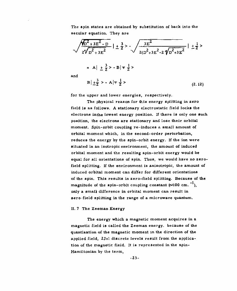
The spin states are obtained by substitution of back into the
secular equation. They are
+3E2 D ±72 >
+ 2 2'e 7D-3-E+ J (D 2 +3E -z_ +VD+E
SAl 3 >-BIT >
and B I+± > - A IT >
for the upper and lower energies, respectively.
The physical reason for this energy splitting in zero
field is as follows. A stationary electrostatic field locks the
electrons inthe lowest energy position. If there is only one such
position, the electrons are stationary and lose their orbital
moment. Spin-orbit coupling re-induces a small amount of
orbital moment which, in the second-order perturbation,
reduces the energy by the spin-orbit energy. If the ion were
situated in an isotropic environment, the amount of induced
orbital moment and the resulting spin-orbit energy would be
equal for all orientations of spin. Thus, we would have no zero-
field splitting. If the environment is anisotropic, the amount of
induced orbital moment can differ for different orientations
of the spin. This results in zero-field splitting. Because of the
magnitude of the spin-orbit coupling constant (NJOO cm. ),
only a small difference in orbital moment can result in
zero-field splitting in the range of a microwave quantum.
II. 7 The Zeeman Energy
The energy which a magnetic moment acquires in a
magnetic field is called the Zeeman energy. because of the
quantization of the magnetic moment in the direction of the
applied field, ZJ+l discrete levels result from the applica-
tion of the magnetic field. It is represented in the spin-
Hamiltonian by the term,-23-

PR " g''
If the coordinates are chosen properly with respect to
the crystalline field, the g-tensor is usually diagonal. In this
case
•g = (gxHxSx + gyHySy + gzHzSZ)
For a pure spin state gx = gy = gz = 2. 003. Thus, we have
P.M . g.1 = gP1 . .
In the spin-Hamiltonian, the small orbital component in
the magnetic moment causes g to deviate from the pure spin
value. Mathematically, this is due to the cross-terms between
H and S in the second-order perturbed energy expression used
in the derivation of the spin-Hamiltonian.
<01 Li k >(X +P l
k E - Ek
which gives for the coefficient of the terms P i s
I <01LiLk>Il 2
k Eo E k
This quantity is added to 2. 003 to form g.
Physically, this quantity can be explained in the fol-
lowing way. To first approximation, the orbital moment is
zero. The presence of spin and the application of a magnetic
field both serve to induce a small amount of orbital moment
-24-

by mixing excited orbital states. The spin interacting with orbital
moment induced by itself gives zero-field splitting. The spin
interacting with the orbital moment induced by the applied magne-
tic field contributes to g. Similarly, the magnetic field inter-
acting with the orbital moment induced by the spin contributes
an equal amount to g. In fact, the deviation of g from 2. 003 is
a direct measure of the induced orbital moment.
(g- 2. 003)i = Z .(XS+P H)
The close relation between zero-field splitting and the
deviation of g from 2. 003 has been pointed out by Bleaney and16Stevens. Namely,
(gi - 2. 003)
-1
X is of the order of 100 cm This shows that a deviation of g
from 2. 003 of . 01 can cause a zero-field splitting up to . 5 cm - 1.
The zero-field splitting is due to the difference in D in different
directions. Therefore, it can be expected to be somewhat smaller
unless the Di are of different signs.
In ions where the ground term in the configuration has
no angular momentum the physical basis for the spin-Hamil-
tonian is quite different, and these relations may not hold.
II. 8 Hyperfine Structure
The term 9. A- T in the spin-Hamiltonian represents
the interaction of the nuclear magnetic moment (spin) of the
paramagnetic ion with its electrons. This is a static dipole-
dipole interaction which is govexned by the relative orienta-
tions and positions of the two moments.
_25-

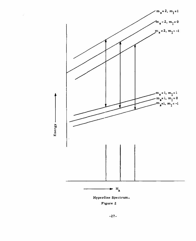
The effect is to split each electronic spin level into 21+ 1 levels,
the spacing between the new levels being proportional to the
value M s of the spin state. As the result, each allowed spin
transition, Am = + 1, is now split into 21+ 1 separate transitions.
The transitions are equally spaced in frequency with
Af=A
when A is expressed in frequency. This group of 21+1 lines
is called the hyperfine structure of a line. This is illus-
trated for the simple case of 1" A.I = A- T, S=2 and
I=l in Fig. 2.
When A is large compared to the width of the line, the
21+1 lines are distinct. They are easily indentified by their
equal intensities and equal spacings. This provides one way for
the identification of paramagnetic ions which possess known
nuclear spin. When A is small compared to the line width,
it simply contributes to the line width as inhomogenous
broadening.
Interaction with the nuclear moments of neighboring nuclei
is also present when such moments exist. This causes addi-
tional splitting of the resonance line. The splitting is naturally
small and consists of a great many lines. Tinkham2 8 was
able to resolve these lines in the resonance of iron group
impurities in ZnF More often, these lines are not resolved
and contribute to the line width as inhomogeneous broadening.
II. 9 The Case of the Degenerate Orbital Ground State
When the ground orbital state is degenerate before
the consideration of spin-orbit coupling, the spin- Hamiltonian,
which was based on a second-order perturbation of the
orbital state, is no longer valid. Spin-orbit coupling will
completely mix the degerate orbital states. The qigenstates
must be obtained by exact diagonalization of the spin-orbit
matrix.
-26-
m z, mI-
bC2 mI=
HyeMn Spectrum.
Figure 2 =
-I'm7-

The liberal mixing of the orbital states generally
results in a large orbital moment. This has the following
effect of the paramagnetic behavior of the ion:
(a) The value of g deviates considerably from 2.
(b) The zero-field splitting becomes very large,
usually beyond the microwave range.
(c) The relaxation time T1 becomes very short.
The last two effects make this case unfit for maser applications.
There ia, however, one special case where, in spite
of an orbital degeneracy, the orbital moment is small. This is
the case of Cr2+ in an octahedral (6-coordination cubic) field,
Fe2 + in a cubic (8-coordination cubic) field, and Cu Z + in an
octahedral field. * These orbital ground states are doubly
degenerate but have the special property that they are non-
magnetic. 29 That is, the matrix of E is identically zero
within the doublet. When the field is not strictly cubic, the
states become weakly magnetic, and the degeneracy is
removed except in the case of trigonal symmetry. Cr+Z
in the rhombic field of CrSO 0 5H 2 0 was found to have a g of
1. 95 for g,, and 1. 99 for g..
In a trigonal symmetry, the states remain degeneracy
but acquire a magnetic moment L z in proportion to the amount
of the trigonal distortion. In this case, it is speculated that a
distortion of the symmetry takes place, which removes the
degeneracy and lowers the energy of one of the states. This
is called the Jahn-Teller effect. 31The effect was originally
proposed for molecular complexes. However, it has been
applied to iron group ions in hydrated salts by Van Vleck. 32
33 2+Bleaney et al. have observed a spectrum of Cu at low
* The 6-coordination cubic and 8-coordination cubic have the
same form of field when expressed in spherical harmonics,
but the polarity is reversed. Thus, the lowest levels in one
become the highest levels in the other.
-28-

temperature which could be explained by the Jahn-Teller effect.
The case of Cu 2 + in the hydrated salts of trigonal symmetry
(fluosilicates, etc. ) is explained in the following manner. The de-
generacy in the trigonal field is removed by a Jahn-Teller distortion.
But the lowest orbital state has three equivalent orientations so
that three separate spectra are observed. At high temperature,
these orientations become mixed, and the spectrum becomes
isotropic. (The spectrum of Cu 2 + in a trigonal field would be
almost isotropic if the orbital ground state were non-degenerate.
II. 10 Other Methods for the Analysis of Paramagnetic Ions
26
The spin-Hamiltonian of Abragam and Pryce was based
on a perturbation calculation in which the crystalline field is
weaker than the electrostatic force between the electrons in the
ion but stronger than the spin-orbit coupling. This made the ground
term in the configuration the starting point in the calculation.
The spin-Hamiltonian is explained in another way by Bowers20
and Owens in their review of paramagnetic resonance. Their
starting point is the configuration. The crystal field acts on
each electron in the configuration, splitting the orbital degeneracy
of the single electrons. If n electrons of the same shell form the
configuration, the electrons are assigned to occupy the n
lowest energy orbitals of an isolated electron in the
crystal field. This forms the ground state. The proper
degeneracy in the orbital ground state is obtained this way.
The form of the Hamiltonian was obtained only from the know-
ledge of the ground orbital state degeneracy and the crystal-
line field symmetry. Therefore, either method yields the same
result. To the inexperienced researcher, it is somewhat
-29-

surprising that the second approach, which ignores the electro-
static repulsion between the magnetic electrons, gives the
proper ground state.
In optical work, however, the approach of Bowers and
Owens is the accepted one. This is known as the crystalline
field approximation because it assumes that the crystalline
field is dominant over the electron-electron electrostatic
field. The reason for this difference in approach is that, as
far as the ground orbital state is concerned, the Russel-
Saunders approach is good. However, the higher energy
levels of the ground term in the crystalline field approach
the lowest levels of the next highest term, and considerable
mixing occurs. The Russel-Saunders coupling is no longer
accurate. Thus, for optical work it is a poor approximation.
Some light is shed on this problem by the recent work23
of Racah, Low et al. They have undertaken a project of
.finding the energy levels and states of iron group and rare-
earth ions in a cubic field. It is to be extended to lower
symmetries. They have found, by use of a computer, the
exact levels and states starting from the LSJM representation.
This is a representation in which the spin-orbit coupling is
diagonal. Although the crystalline field is stronger than
the spin-orbit coupling, this introduces no inaccuracy because
the computer solves the problem exactly without resorting
to perturbation methods. All the terms in the configuration
with the ground S-state are used.
The result shows that the ground orbital state is very
nearly the state given by the Russel-Saunders coupling. Most
of the excited states cannot be represented even approximately
by the Russel-Saunders coupling.
-30-

II. 11 Koster's Mqthod
Koster '34 has developed a group-theoretical method
by which the number of independent terms required in a com-
plete spin-Hamiltonian is given.
In this approach, it is assumed that the eigenstates
and energies for the complete Hamiltonian, in the absence of
a magnetic field, is solved. This includes all the terms in the
complete Hamiltonian including the crystalline field and
spin-orbit coupling. The Zeeman energy term is then applied
as a perturbation. This method predicted many more inde-
pendent terms than those included in the spin-Hamiltonian
by Abragam and Pryce. For example, for S= 3/2, the spin-
Hamiltonian of Abragam and Pryce terminates with terms in2 3
S. . Koster's method includes the terms HiS .1 1We note that such terms are allowed by the time-
reversal symmetry of the spin-Hamiltonian. In fact, they
would have appeared in the original Hamiltonian if the per-
turbation were carried out to the fourth order. But so would
a number of other terms of the form H S and H 3S. Why
are these terms not predicted in Koster's complete spin-
Hamiltonian?
The reason lies in the fact that Koster's method still
had to resort to the perturbation method for the final step.
It is a first-order perturbation expression. Higher order
perturbation is necessary to produce terms of higher power
in H. Physically, omission of higher order perturbation in
the orbital Zeeman energy means that the induction of
orbital moment by the magnetic field is ignored. This is
actually a very good approximation. The spin-orbit energy,
which is the next least powerful term in the total Hamiltonian,
is at least 100 times stronger than the orbital Zeeman term
at practical magnetic fields.
-31-

Experimental evidence of the additional energy terms35
predicted by Koster has been reported. The effect is
small. It appears that in most cases they can be neglected.
II, 12 The Theory of T 1
When the spin system is not in thermal equilibrium
with a thermal bath with which it is in contact, it will relax
into equilibrium in a characteristic time T1 in the absence of
a driving source. The relaxation time T 1 is a measure of the
contact (or lack of contact) with the thermal bath.
The problem of spin relaxation has been studied by36
Van Vleck. His results were not completely satisfactory,
but the approach is generally accepted. The principles of his
theory are reviewed here. Mattuck and Strandberg 7 9 have
restudied the problem and have arrived at substantially the
same results.
Quantum mechanically, thermal spin relaxation is
treated as the transition between spin-states under the excita-
tion due to the thermal bath (in this case, the lattice). The
transition rate is the reciprocal of T .
Spins can interact only with magnetic fields. The
lattice, on the other hand, is non-magnetic. Therefore, to
first order, there is no thermal contact and T1 is infinite.
However, a contact of the second order does exist. In this
process, the time-varying electric field, due to the thermal
vibration of the lattice, interacts with the electrons in the
paramagnetic ion. This affects the orbital moment of the ion
which, in turn, interacts with the spin to induce the required
transition.
The total Hamiltonian for the spin and lattice in mutual
contact is
=o + X XL+)+so+40 OL+ XSS (Z. 13)
-32-

MO is the energy of the orbital state in the crystalline field
without the spin-orbit coupling, K L is the energy of the lattice
vibrations, )4 is the Zeeman energy, M(so is the spin-orbit
energy, )(OL is the orbit-lattice coupling energy, and HSS ip
the spin-spin interaction which introduces line width. X 0 +
)(L is taken as the unperturbed Hamiltonian, and the remain-
der is the perturbing Hamiltonian. It acts on the manifold of
eigenstates of ( 0 and *(L"
The transition from the spin state I + > to -> is
computed by using a "new" effective Hamiltonian.
new(ii,) Y D ('(ij)j'(j, k)]X'(k, i')] (2. 14)
j,k hv(ij)hv(jk)
The indices, i, j, k and i' designate compound states of
spin, orbit and lattice. i and i' designate the ground orbital
state with spin states I - > and I +>, respectively.
The matrix element H'(ij) is a sum
-'(ij) = So(i) +)4OL(ii) +) z(ii) +H}ss(ii) (2.15)
When the ground orbital state is a singlet, Hso(ij) and
HOL(iJ) are zero whenever j contains the orbital ground state.
Therefore, the sum over j and k are over states containing
only excited states. When Eq. (2. 15) is substituted into Eq.
(2. 14) among the products we find
)XS0 (p + n i , q "'hi)XS0(,q- n i, r-n 1))4 OL (r-n i , P-n i+l)
(2.16)[E(p) - E(q)l[E(q) - E(r)]
and all the permutations thereof. Such terms represent third
order transitions from the state I + > to I - >. At the same
time, the lattice state changes from n. to n. +1. The spin and1 1
the lattice exchange energy. Second order terms cancel out
almost completely.
-33-

The transition probability is proportional to the square
of new(ii'). It be seen from (2.16) that the probability is
proportional to . is the spin orbit coupling and Ais the
energy separation between the orbital levels in a crystalline
field. These separations are not equal by any means, but for
a qualitative discussion, they are all equated to a single A.
The factor Swas previously encountered in the deriva-
tion of the spin-Hamiltonian. It represents an orbital moment
induced by spin-orbit coupling in an otherwise "quenched"
state. It was responsible for zero-field splitting and the
deviation of g from 2. In fact, the deviation of g from 2 was
given by . Therefore, the g-factor is a convenient index
by which relative relaxation times can be estimated. A long
relaxation time is incompatible with a large deviation of g
from 2.
The strength of the crystalline field enters into T1
in two ways. Ais proportional to the strength and so is1
X L" Since I or the transition probability is proportional
to 2MOL
it appears that a strong field results in a longer relaxation
time. The quartic dependence of the transition probability
on X indicates that a very large variation of T 1 is expected in
the iron group. V2 + has a X of 55 cm) 1 while Cu Z + has-1-852 cm . This would indicate a ratio of relaxation times
of the order of (15) 4 50, 000.
°34-

CHAPTER III
THE RELATIONSHIP BETWEEN THE MATERIAL
PARAMETERS AND MASER PERFORMANCE
II. 1 Bloch's Equations
A brief review is made of the two-level maser to show
the relation between parameters of the maser material and the
maser performance. This relation is valid also for three-level
masers with only a simple correction.
We have a paramagnetic solid containing N particles per
unit volume, each with a spin of 1/2. In the presence of a mag-
netic field, the spin state m s = 1/2 will have an energy 2PH0
higher than the state m s = -1/2. Here P is the Bohr magneton,
and H is the dc magnetic field. Boltzmann's distribution
gives a population of the lower state which is larger than the
population of the higher state by
1 -A E/KT
AN = NO 1 (3.1)01+1 EK
where K is Boltzmann's constant, and T is the temperature inAT
Kelvin. If AE << KT, AN T N o = . We have as the result
a net induced magnetic moment which we shall call
AEILo = P AN = P AE
The net angular momentum in units of1, is -A= M o . The
analysis of a maser can be made while restricting our-
selves to M0 because the remainder of the spins will always
cancel itself out.
The behavior of the net moment M under a time-0 37
varying magnetic field excitation was analyzed by Bloch
-35-

in connection with nuclear magnetic resonance. The treatment
was made by the now famous Bloch equations. These are classi-
cal equations. However, they give results which are in perfect
agreement with experiments and with quantum mechanical
analysis for the simple cases where quantum mechanical analysis
is possible. In addition, relaxation effects can be included in a
simple way; whereas, in a quantum mechanical treatment it is
extremely complex.
The equations are basically the equations of the spinning
top.dFN1 = T (torque) = yMXR (3.2)
y is the ratio of magnetic moment to the mechanical angular
momentum. (For an electron this is ?.- =. 92?xL07 . ) Here, H
is the total magnetic field. Equation (3, 2) can be written for a
rectangular coordinate system rotating about the z-axis with
an angular velocity w.
dM(31dMt-- -wXF + yK4XFI =X(yll + W)(.
where H is now
H " H' H'H + H cost] + [ cos 2Wt + f+ . t-sin2t]
The three components of this equation are
dM 2 YHf.dt = y -(Ho0+ H r. f. CosWt) +W] +M z . __T sin 2wt
dM H - H -
= [.Y(r.. + .- Cos 2wt)] -Mx[ y(Ho + H 2 fcos Wt)+W]
dMY f._--M x sinZ t-M y[(Hr f. Cos 2wt)]
-36-

As it stands, these equations are very difficult to solve.
A very large simplification is made by ignoring the terms which
are time varying. This would be justified if the resulting
solution turns out to be a slowly varying function compared to
the terms which were ignored.
The simplified equations are
dM
7 M y (yH o + )
dM HIr.f..=t Mz y YZ- Mx 0o+ (3.4)
--- = - Myy 2
The solutions are
M M°Hr" f ." sin Q/2t
M MYHr"f"(YH °+) 1)
x - 0 (l-cosQl12 t) (3.5)
M N2r f. 1/2 (YHo + W)2M 0 -o r.cosQ + Qz Q 4 Q
-Y 2Hr f.
where Q = 4Z + (YH0 + W)
In the special case of yH 0 +W = 0,
M =O andx
Mz = M 0 cos Y"r-- t (3.6)
HMy = M ° sin y -r.f. t
This shows that M rotates about the x-axis with an angular
velocity
-37 -

YHr (3.7)
Noting that only one circularly polarized component of Hrf.re-
mains in the solution, we can call it H' to simplify the expressions.
W1 = yH' (3. 8)
This is just a free precession of M about the rotating fieldo
H'. This condition is referred to as magnetic resonance.
The equation and solution just given do not include
relaxation effects. Bloch took relaxation into account by
inserting two damping times T 1 and T2 in the following
manner.
dM MSxMy(yH ° + W) - -
2
dM M-M .( -9)
dM z (Mz-M o )= -MyyH -
H' is the circularly polarized component of H .f.rotating at an
angular frequency +w about the z-axis.
These relaxation times are necessary for the following
reasons. First, there is a continuous drainage of energy from
the spin system by whatever mechanisms which exist that are
trying to bring the spins into thermal equilibrium. The energy
of the spin system is proportional to -M z when the d. c. mag-
netic field is in the z-direction. Therefore, a time constant
T is inserted to point M z towards its thermal equilibrium
value M . Secondly, the net spin moment M is not a single
moment but is composed of many spins oriented in the same
-38-

direction. This orientation is imposed by the Boltzmann's
distribution when the M is in the z-direction. But when M0 0
is in the x-y plane, it should relax towards the thermal equi-
librium value for this direction which is zero. In addition,
the dipole-dipole interaction between the component spins try
to destroy M o . Thus, for transverse components of M,
Bloch added a damping term
MLML-, ,where T < T.2
The solution to Bloch's equation with relaxation is very
involved for transient cases. The steady state solution
is very easy to obtain. It is
H(yH)+1 + o(Y0 + _2+T-2 ] ".-
M = (3.10)
y (o+)y21 zT 1I T 2 T
yH'Mo (yH 0+W)
Y T2Y)2+1 0 T 2, TY
M = M 0 (H0+
T Z2 1
(yH 0 +W) +y H'
at resonance yH o +w = 0. Then
M =0x
-39-

yH'M oT 2 11 + yH'Z T1T 2
MM =0
S1+y -YH'Z T T 2
If T were infinite, M x = My = M z = 0. When T1 is finite,
as it always is, M y and M become non-zero. Physically, it isy zeasy to see why My must not be zero. A finite T I means that
losses are present. It indicates the presence of a damping force
on R. In a steady-state condition, an equal and opposite force
must exist which balances out the damping force. This is
provided by IXR = H " M . For any transfer of energy to takex yplace in the total spin system, some transverse M must be
preserved even when T 2 is present. The non-zero value of Mz
represents the extent to which the damping forces V towards
its thermal equilibrium value.
The amount of energy absorbed by the spin system fromthe resonant magnetic field can be computed by simply equating
it to the loss in the system.M -iM
P= z T 1- ) 2PH = rate of energy loss due to T1.
T 2T2 2,2 T, 3 zNH 0Y + wo) +-- + y]' rT22
The results of Bloch's equations can also be expressed
in terms of susceptibilities.
-40-

I = 2P MH H
MxDC 2 H
f 0 (3.13)
xM YM. 2A
x"Ai = 02p -2
rf x T2 (yH +)2 +1 +Y 2H T
T 2 T2
When the standard phaarer notation is used for the time-
varying quantities, the susceptibility can be represented as
a complex quantity. x = (x'+jx"), where x" is a negative be-1 , ,2
cause y is negative. In terms of the susceptibility, P=- -wx"H'2The solutions to Bloch's equation have certain weaknesses.
One is that the equations do not allow for the maintenance of a38
transverse moment. This was pointed out by Redfield. Thepreservation of transverse moments for times up to T has
391
been demonstrated .experimentally. This is of some
consequence in transient behavior when large differences
exist between T 1 and T 2 but cause no difficulty in steady-state
electron resonance. Another difficulty is that the power ab-
sorption pattern, as a function of frequency which is referred
to as "line shape, " is always Lorentzian with the Bloch
equations. Experimentally, it is not always Lorentzian.
The value of x" obtained by Bloch's equation is inde-
pendent of the magnitude of the individual moments which
make up the total moment. This is an expected weakness of
a classical treatment. The proper dependence can be found
by a simple quantum-mechanical treatment omitting explicit
relaxation effects.
From the Bloch's equation we had2 1 2,
P = -2W"H' = - -wxH
where H' was one circularly polarized component of H . Therefore,x
-41-

H = 2H'. We can consider this to be the definition x". The samexpower P can be written
P = (number of transitions) (energy of each transition)
x(rate of each transition) = AN. AE " A
where A is the transition probability of a single ion. The quan-
tum mechanical transition probability is given by
A = 1p(k)I HknI
where Hkn is the matrix element of the perturbing Hamiltonian
which induces the transition between states d k and nP anddN .I h e st sgv nap(k) is the denstiy of states .If the density is given as
dN then k
2w
A p(w) I Hkn 2
For a perturbing Hamiltonian gp H x - Sx
I Hkni 2 =g 2P 2 1<kH xS x l n>1 2
If the spin states are pure, only one component of Hx, namely
H' contributes to the transition, giving
2 2 2 22
Hk I =(g P Ht /4)1 <kI S+I n>I1
p(w) can be interpreted as the line broadening. We can identi-
fy this with
1
2 1 2 2 T1wT 2[ yHo +w)+ - 2 + HY
T 2 2
-42-

which we found in the solution to Bloch's equations. If A
represents the transition probability of one ion, then p(w)
must be normalized so that
S p(w)dw = 1.-00
Integration of the line-shape factor
1
2 1 2 2 T 1TR-YH+ W) + . + 2H,TT 2
shows it to be r. Therefore,
w(T) [ 0
T 1 2 2-rT2 [(yHo+c )z T--2 + y H'
Substitution into P gives
Pw t g ZH' J<k I S+j n> IP= AN TE .
T2 [ (YHo+ w) 2+- 1 +Y2 H'2TT2 2
> 122AN' - 2 2 2 k n
-1 ,H 1 1 2 ,2 T 1iT-[ (¥Ho+W + + H" '
T 2 2
x LZg g P22 I <klS _+ I n> 12
4 T 1[(yH+ W)2+ T + Y 2 H, 2 T 1 (3.14)
T 2 2The line width of the transition is given by the factor
p(w). If the applied r. f. magnetic field is sufficiently weak so
that the last term in the denominator can be neglected, the
half-power point in the paramagnetic absorption is given by
-43-

(YH0 + 1
When the applied r. f. magnetic field is large enough so the
last term is not negligible, the half-power point is increased
to 2
(-yH +W) + N H'0 T2 2
The maximum absorption which occurs at resonance is also
reduced because of the increase in the denominator. This
condition is called saturation.
IJI. 2 The Reflection Cavity Maser
A maser can be constructed by placing a suitable
paramagnetic material within a reflection cavity. The equi-
valent circuit of such a device is shown in Fig. 3.
L 0 R: Rc Rm C
Figure 3
In this circuit, L and C represent the cavity. R representscthe resistive and dielectric losses in the cavity walls and in
the maser material. Rm is the absorption due to the imaginary
part of the susceptibility, x" . The relation between x" and Rm
can be shown as follows. The power absorbed due to x" is
-2 x"H'2 1Z- X x
-44-

The Q of a cavity due to losses arising from x" alone is
wX(energy stored)Power dissipated by x"
2wH 2' Hdv
- x" fH dvx
2x1 (3, 15)
where 1 =f H dv
We recall that H' is one circularly polarized component of
H"L ; whereas, HA is the total magnetic field intensity, Thus,is always less than unity. If Q is the Q due to Rc alone,
the effective resistance representing x" is
RcQ Rc . 2Rm -11o C (3.16)
0 0
The total conductance of the cavity at resonance is
I I
R Rm c
The cavity is connected to a source and load through
a waveguide. This coupling can be represented as a trans-
former as in Fig. 4. The source (load) can be transformed
to the secondary side to give a new equivalent circuit as in
Fig. 5.
In this maser the source and the load are the same.
It can be shown that such a maser suffers from the fault that
a large portion of the source power is dissipated in the source
(load) impedance without being amplified by the maser.
-45 -

This weakness is avoided by an insertion of a "circulator"
between the maser cavity and the load and source. The circulator is
a three-terminal-pair device in which energy flows only in one
sequence: a-+ b--*c. A maser using the circulator is shown in Fig. 6.
Now all the source power is incident on the maser. All the
output (reflection) from the maser is delivered to the load.
The power delivered to the load is obtained by simply
taking the reflected power from the cavity as computed from trans-
mission line equations.
M
R L R R
Figure 4
-46-

Ll R R C0 C m
Figure 5
Load
-47-

ZL+ZO Y 0 (3.17)Z L+Z o Yo+YLL
PL = P in' r2 (3.18)
For our maser we have
y = 10 R1
0
I 1RnII R 1
l/R' -1/R -I1/Rr = R-m R (3.19)
1/R' +1/Rm+/ R co m
The condition for amplification is that
co> r > 11 1
This is achieved when r- + -R becomes negative so that the
numerator of Eq. (3.18) is larger than the denominator. When+ -L is sufficiently negative to make the denominator vanish,
Rm Rcthe maser becomes an oscillator.
The gain of a maser was given as
rZ =m c 0") ir- r
-7- = I I
R' is the parallel resistance of Rc and Rm . To obtain gain, thecfollowing conditions are necessary or desirable:
(1) R m < 0
(2) IRmI <Rc3) 1 - + be as small a positive quantity
0 W~o + c as possible
-48-

It is clear that to obtain amplification with a given Rc and Ro, we
need a negative Rm with IRm j sufficiently small. This, in turn,
demands that x" be sufficiently large. x", in turn, was given by
(3. 14) at resonance: -& AN41 2 T 2 . AN is the population difference
between states 1 and 2, and jL2 is the matrix element of the spin
moment between states I and 2. This shows that gain is easier to
obtain when
(I) The quantity AN is large. In other words, we have
a large inversion.
(2) L12 is large.
(3) T 2 is long.
Going back to the expression for gain, we see that another
way to obtain higher gain when the conditions for amplification are
already satisfied, is to increase R. For a given source and load
impedance, this indicates-that the coupling between the input-output
waveguide and the maser cavity should be made small. While this
is certainly true, it restricts the bandwidth.
The bandwidth of the maser can be limited by either the
cavity bandwidth or the paramagnetic resonance line width of the
material. The addition of the maser material with negative
resistance serves to raise the Q. The expression for cavity
bandwidth is
R RAf f( 1+ + 1c + cRm Q(3.20)
L m c c 0
For negative R m
f Rc - Rc (3.21)
c 0 m
According to this expression, the cavity bandwidth of the maser
cavity is a function of both R' and Rm.0 m
-49-

The bandwidth of the empty cavity, when it is decoupled
from the load, is determined by Qc" This is about 5, 000-10, 000.
The corresponding bandwidth at 10 gc is about Z mc. The actual
cavity bandwidth for a maser can be considerably narrower or
broader. The presence of RI broadens the bandwidth while the
presence of a negative Rm reduces the bandwidth.
When the bandwidth of the maser is limited by the cavity,
Terhune4 0 shows that, although the gain-bandwidth product is not
constant, the product (GI/2- 1). B is constant for a given Rm and Rc .
(G /-1) • B=
l/QL -1/Q M-l/QC f 1Zf 1
IjI/QL -I/QM+l/Qc f QC QC 0 L QM I .( i
For a negative Rm, it is 2f (I
If the gain is increased by increasing R, the bandwidth is
correspondingly decreased. The gain-bandwidth product is increased
by decreasing I R MI.
If we attempt to obtain a very broad bandwidth for a given
Rm , RI must be made low. However, a limit to this approach isM0
imposed by the bandwidth of the magnetic resonance. The solution
for x" was Eq. (3.18).
I
2 1 2 1T 2 [(H+ )Z + VH' TT 2 2
In this expression resonance is given when jH o+w is set to 0. That is,
W = -jH
At a frequency w' 4 w,
-50-

tH ° + w' = A, where Aw= w - r
1X1 = 1 H 2 T1
22 TI 2 2
y H -' is very small at power levels applicable to normal maser2
operation.
The magnitude of x" is I of the maximum value when A= I
Although the line width of the resonance and the bandwidth of the1
maser amplifier are not directly related, it is clear that y- gives a
reasonable measure of the bandwidth of the amplifier when it is
limited by the line width of the material. This is certainly the case
for non-resonant masers such as traveling-wave masers which
we have not discussed. For very wide-band amplifiers, T 2 must
be short.
Up to this point, the relaxation time T1 has not been mentioned
explicitly in the maser properties. Yet, it is probably the most
important parameter for maser materials. T1 enters the problem
through the factor (N2 -N 1 ) in the expression for x", which was
already seen to be the determining factor in the gain of a maser.
Bloembergen's 4 three-level scheme, given in the intro-
duction, is to apply a sufficiently strong resonant excitation be-
tween the lowest and highest levels of three energy levels so that
their populations, N1 and N 3 , are almost equal. Thip excitation
is in competition with T1 , which represents a process that is
trying to maintain thermal equilibrium.
The excitation power required to make N 3 =N1 can be
computed. At thermal equilibrium,
NAE0
N3 - N1 = -AN= n .
When this term is too large to be ignored, it will reduce x",
and thereby, the gain. The maser is then in nonlinear operation.
It is then said to be saturated.
-51-

When N 3 =N1 , the deviation of AN from thermal equilibrium is
just AN. The rate of energy loss through TI is then
P= NA
N 0(A.E)
2(KTI T1
It is instructive to estimate this quantity, Suppose N o = 1020
AE = hx3xl0 1 0 = 1. 98x106 ergs
KT = 5. 35 x10 "1 6 ergs at 4. 2 OK
Then, TI= 10
P = 335 watts.
This is the power which must be made up by the exciting field.
It must be applied at a very low impedance (very strong mag-
netic field) for saturation. This can be seen from the saturation
condition in the solution to Bloch's equation. In the actual maser,
the cavity must be optimized for the signal frequency. We are not
free to optimize the cavity for pumping. This factor and the
additional losses in the cavity require that the pump provide
several times as much power as that just estimated. It is-6
evident that the requirement is prohibitive at T1 = 10 " . The
effect of heat produced by such high power dissipatibn must also
be considered.
To sum up, a short TI demands that the pump power be
prohibitively high for maser operation. Such a high pump power
raises the temperature of the maser even in a thermal bath.
Because T1 decreases rapidly with termperature, the pumping
becomes inadequate and maser action cannot be obtained.
Finally, we consider the question of how the three
required energy levels are to be obtained.
-52-
Confining ourselves to Zeeman energy levels, we re-
quire paramagnetic ions with an angular momentum of at least
1 to give the required three states (3=2J+I). In the discussion of
the relaxation time T1 , it was shown that the presence of an
orbital moment leads to a short relaxation time, Therefore,
we require the orbital moment to be as close to zero as
possible.
If the orbital moment were strictly zero, we are left
with a pure spin state with (2 S+l) - fold degeneracy. I S >1,
the application of a magnetic field will yield the required
number of levels as in Fig. 7. Unfortunately, this scheme
will not work because the spin states are pure. The only
transitions possible through a time-varying magnetic field
are those which co.nnect states whose values of M differ by I.
All of these transitions are resonant at the same frequency.
It is not possible to pump between two states which are not
adjacent to each other.
The situation is rescued by a small amount of orbi-
tal moment. It was show n that a small amount of orbital
moment in the presence of a sufficiently anisotropic crystal-
line electrostatic field will partly remove the spin degeneracy
without the application of a magnetic field. This was called
zero-field splitting. When the magnetic field is added, the
Zeeman energy is added to this initial splitting to completely
remove the degeneracy. The total result is that
1) The resonant frequencies for different allowed
transition are now different.
2) The spin states can become mixed so that many
more transitions become allowed. Pumping is
now possible between a number of levels.
-53-

H
Energy levels and allowed transitions in a
pure spin state. Example: S= 5/2.
Figure 7
-54-

The Zeeman energy is proportional to the magnetic
field. For a pure spin state the relation is
AE = 2 H
for allowed transitions. For a signal frequency of 10 kmc, the
field required is 3. 5 kilo-gauss. While this is not an unreasonable
value, the magnetic field requirement becomes prohibitive for
very much higher frequencies.
When zero-field splitting exists, the incremental ratio
of frequency to magnetic field can be improved in some cases.
But, the biggest advantage of the zero-field splitting is that it
simply substitutes for Zeeman splitting. If S is the magnitude
of zero-field splitting given in frequency, it reduces the re-
quired magnetic field by 2.8xi06 from the value required for
pure spin at the same frequency of resonance. In fact, if the
proper zero-field splitting were avaliable, no magnetic field
would be required. Masers based on this scheme have been41
discussed by Bogle and Symons. It has been successfullyorino42 3+.operated by Kornienko using Fe impurity in A12 0 3.
As the Zeeman energy becomes large compared to
the zero-field splitting, the energy levels and states approach
the condition for pure spin, and the difficulties associated
with pure spin are encountered once again. For this reason,
the upper frequency limit for a maser material is given
approximately by the zero-field splitting. Thus, in order
to extend the range of the maser to higher frequencies,
materials with higher zero-field splittings must be developed.
III. 3 Summary
The conclusions of the preceding sections are summed
here with some additional remarks.
-55-

The qualities desired of a good maser material are
(a) A long relaxation time, T1
This is necessary if inversion is to be accomplished
without excessive pump power and consequent heating of the
maser material.
(b) *A large transition probability between the inverted states
The susceptibility is proportional to the square of this
quantity.
(c) A large density of paramagnetic ions
Inversion is proportional to the density, other things
being equal. However, density should be kept low enough
to keep magnetic ions separated. Excessively high density
also leads to another type of relaxation which we have not
mentioned: cross relaxation. This can lead to complications
-- some good, some bad. 3
(d) A long T*
The susceptibility is proportional to T 2 . There is an
intrinsic part which is just inversely proportional to the
density of paramagnetic ions. In many ions, there is an
additional component due to the nuclear moments within
the ion and in its neighbors. This should be reduced to a
minimum. Should a large line width be required for a
wide-band maser, the line can be broadened to the desired
value by increasing the density of paramagnetic ions. This
will also help (c).
(e) Zero-field splitting equal to or larger than the intended
maser frequency
This is necessary to make pumping possible and to
reduce the amount of magnetic field required. Because the
See the following page.
-56-

T , which is the characteristic time for destruction of the
magnetic moment normal to the dc magnetic field, is often
discussed in terms of two separate effects. One is a destruc-
tive interference of individual moments due to their having un-
equal precession frequencies. This can arise from slightly
different environments (position in a magnet gap, local distor-
tions in a crystal, etc. ) for different spins. A slight varia-
tion in precession frequency among the spins causes spins,
which were initially all aligned, to lose their alignment in
a short time. This is called inhomogeneous T2 . The other
effect is the resonant interaction between spins of the same
precession frequency. The interaction removes the degeneracy
and thus broadens the line width. This type of line width is
described as "homogeneous T 2 . "
The transient behavior of a spin system differs consider-
ably, depending on whether the line width is due to homo-
geneous or inhomogeneous Tz. However, in steady state,
as in a three-level maser, the distinction need not be made.
-57-

need for very high frequency masers is most urgent, high zero-
field splittings are desired.
CHAPTER IV
A SURVEY OF POTENTIAL CRYSTALS FOR THREE-LEVEL
MASERS
The qualitites desired in a crystal for three-level masers
were discussed in a previous chapter. The problem of finding
or making crystals with those desired qualities is now consi-
dered. This problem has been discussed previously by44
Singer. There, only crystals which were available syntheti-
cally were considered. Here, consideration is extended to all
crystals. The problem of finding or making crystals with
those desired qualities can be divided into two parts. The first
part is to choose the paramagnetic ion suited to the purpose.
The second is to choose a suitable diamagnetic, dielectric
solid to serve as a host for the paramagnetic ion. Of course,
the two parts are not completely independent. The choice of
one is bound to influence the other.
IV. I The Paramagnetic Ion
The conditions which govern the choice are
1) Long TI.
2) Long T 2 .
3) At least three spin levels.
Van Vleck's theory, showed that spin-orbit coupling was
the mechanism which was responsible for T . A long T 1
requires a small spin-orbit coupling constant X and a small
orbital moment. States which belong to terms of L=O satisfy
this requirement. In addition, even where L 4 0, crystalline
-58-

fields of the proper symmetry were found to split the states in
the manifold of L in such a way that left a singlet state with the
lowest energy. In such a singlet state, the only'orbital moments
present were those re-induced by spin-orbit coupling. This wasXa second-order process proportional to - , where A. is the
energy from the ground state to a higher obital state j. There-
fore, in such cases, in addition to a small X, large Aj's are
required for long T I. This second condition dictates that the
ground orbital state be a singlet in an octahedral or cubic
symmetry. This is because the common environments of the iron+
group are usually very close to one of these two symmetries.
The exact, actual symmetry may be lower because of small
deviations, but the removal of degeneracy by such lower sym-
metries will not result in &s large engouh to produce good
quenching.
An exception is made for "non-magnetic" doublets dis-
cussed in Section I. 9. The component states in such a doublet
have quenched orbital moments. In addition, there is no first
order mixing between the components under spin-orbit coupling
so that the quenching is preserved.
The strong dependance of T1 on X must be noted in selecting
ions for long TI.
With respect to T, the following combinations of ion and
symmetry are suitable.
Ion Symmetry Orbital Ground State
Ti 3 + cubic non-magnetic doublet
* cubic singlet
V 2 + octahedral singlet
Cr 3 + octahedral singlet
CrZ+ octahedral non-magnetic doublet
MnZ+ any symmetry L = 0
Fe any symmetry L = 0
Fe 2 + cubic non-magnetic doublet
Co 2 + cubic singlet
Ni2 + octahedral singlet
Qu 2 + octahedral non-magnetic doublet+ See the following page.

Among the combinations listed, Fe 3+ and Mn 2 + are
superior to the others. Cr 3+ in an octahedral field is also
better than the others because of the large energy gap between
the singlet and the next lowest orbital and a small spin-orbit
coupling. Triviwlent ions have larger crystal field splitting and
are, therefore, to be preferred. The non-magnetic doublets
are generally inferior to the singlets. Cu 2 + and Ni 2 + have
rather large values of X. Therefore, they are less desirable.
The contribution by the ion to T2 is the inhomo-geneous broadening caused by the nuclear spin. When the
hyperfine splitting is large, the lines outside the intended
bandwidth of the maser do not participate in the maser action
and is wasted. The effective density of the spins is reduced.
The choice of ions with respect to T2 falls on those ions with
a minimum of nuclear spin. The desirable ions are Fe2 + , 3+
2+ 2+,3+Ni and Cr 2 ' , in the order given. 2+ 3+
The condition S > I is also satisfied by Fe
Ni and Cr
Ions which satisfy all the conditions are Fe 3+ in2+ 3+ 2+
any symmetry, Cr , Cr and Ni in octahedral symmetry
and Fe 2 + in cubic symmetry.
In addition to the iron group ions, the two S-statewae arhs G 3+ adu 2 +
rare earths, Gd + and Eu2 , display long T1. The other rare
earths have short relaxation times due to excessive orbital
moment. Eu2 + is not suited for masers because of its nuclear
moment.
The useful ions listed in the probable order of3+ 3+ 3+ 2+ 2+ 2
desirability are Fe Cr , Gd , Ni , Cr and FeZ+.
+By cubic symmetry, 8 negatively charged neighbors in a
cubs are designated.By octahedral symmetry, 6 negatively
charged neighbors in an octahedron are designated.
-60-

IV. 2 The Host Crystal
The desired qualities in a host crystal are
a) Absence of paramagnetism for ferromagnetism on the part
of the pure host crystal itself.
b) A minimum abundance and strength of nuclear moment, par-
ticularly in the ions immediately adjacent to the paramagnetic
impurity.
c) Sufficient asymmetry to produce a large zero-field splitting.
d) Good stability. Particularly, resistance to thermal stress
and moisture.
e) A small unit cell, so that all the paramagnetic ions are
magnetically equivalent.
f) If possible, cations of the same valence as the intended para-
magnetic substitute.
g) Cations whose ionic radii are similar to the radii of the
intended paramagnetic substitute.
h) If possible, sufficiently low symmetry to remove orbital
degeneracies in the ground state.
i) Very high resistivity.
The condition on nuclear moment rules out a very large
number of the most commonly available crystals. All the
halides are ruled out because of their nuclear spin. Also ruled
out are all the hydrated crystals because of the nuclear spin
of hydrogen. For the same reason, most organic crystals
are not suitable.
The crystals which may be suited are the oxides, car-
bonates, sulphates, tungstates, chromates, silicates, silicideg,
sulphides and carbides of metals which are not in themselves
paramagnetic and which have a low abundance of nuclear
moment.
The condition that large zero-field splitting should result
is not as easy to apply. The theoretical relation between the
zero-field splitting and the strength and symmetry of the crys-
talline field is well known, but so far, the numerical values of
-61-

the parameters which enter into the expression are not known
with sufficient accuracy to allow even approximate calculation.
We do not know, however, that a cubic symmetry cannot cause a
zero-field splitting in S=l or S=3/2. Therefore, in the case of theCr3+ 2+
paramagnetic ions Cr or Ni , a cubic symmetry must be
avoided. A word of caution is in order here. The symmetry,
which in involved, is the point symmetry of the paramagnetic
ion site and not of the crystal as a whole. These two symmetries
usually differ, the point group being lower.
It was noted previously that the positions of the nega-
tively charged neighbors about the metallic cation are usually
very close to octahedral when the radius of the metallic ion
is small compared to the radius of the negative neighbors.
When the negative neighbor is oxygen, this condition is
usually satisfied. We can speculate that this relation is not
followed as closely in the case where the neighboring oxygens
belong to tightly-bound complexes such as SiO4' s04, C0 3
CrO4 or WO 4 . In such cases, the oxygens may not be free
to pack themselves as closely and regularly about the metallic
ion. The regularity can also break down when the metallic
ion is comparable to or larger than oxygen in radius.
The unit cell should be small in order that the para-
magnetic ions are not placed in a number of sites which do not
give the same spectrum. Such a case reduces the effective
number of ions participating in any one resonance except for
special orientations of the magnetic field. By a large unit cell
we mean that the unit cell contains a large number of molecules.
Magnetically, many of these may be equivalent. Two sites
related by inversion, for example, are always equivalent
magnetically because of the inversion symmetry of all para-
magnetic spectra. The number of nonequivalent sites is also
reduced when the spin value S is small or the symmetry is
-62-

very high, for we have seen that, in these cases, details of the
symmetry fail to be registered in the magnetic spectra. If the
sites in a unit cell are nonequivalent only because of these
details which cannot be registered in the paramagnetic spectrum,
the sites become equivalent magnetically. In many cases, even
when the sites are not completely equivalent, there are ample
special orientations which make them equivalent to make them
useful in maser work.
The requirement of proper valence is not a stringent one.
It is true that extensive replacement of the cation by single
impurity requires the valence state of the replacement ion to
be the same as the original ion. For dilute substitutions of less
than .1%, this is not necessary, particularly if the crystal is
not annealed. The excess or deficiency of charge can be
neutralized by a compensating impurity or by an additional
anion in the nearest interstitial. If the interstitial anion or
charge compensating second impurity is close enough to the
paramagnetic ion, the symmetry about the ion is altered suf-
ficiently to influence the spin resonance spectrum. TinkhamZ8
has observed such spectra for Cr 3 + in ZnF2 . Very often,
however, the compensation is sufficiently far away so that
no detectable change occurs in the symmetry about the
paramagnetic ion.
Until recently, it was believed that substitutions could
not occur if the ionic radii of the ions to be exchanged differed
by more than 15%. However, the research in maser materials
within the last two years has shown that substitutions up to the46order of . 1% may be possible in many cases.
The requirement that the resistivity be very high is
obvious. Even a small resistivity would greatly reduce the
Q of the maser cavity. Furthermore, at microwave fre-
quencies, conductivity leads to skin effect which removes the
-63-

interior of the crystal from participation in maser action. In
this respect, the sulphides must be examined carefully. Some
of the sulphides are fairly good conductors or semiconductors.
Galena (PbS) is a good example.
Some of the sulphides have been used as hosts for para-
magnetic impurities. Mn2 + in ZnS and EuZ + in SrS are notable
examples. Sulphides are not always ionic, and many of them
may prove unsuitable for masers. The same situation exists
with carbides and silicides.
Armed with the considerations stated above, we can
examine the compilation of inorganic compounds given in the47
Handbook of Chemistry and Physics, WyckoffIs Crystal
Structures 4 8 and the International Tables for X-Ray Crystallo-
graphy. 49 Two facts stand out in such an examination.
a) The lack of suitable crystals which give a cubic
(8-fold coordination) symmetry. The CaF2 (fluorite) structure
is the only such structure. All but one member of this class
must be rejected for one reason or another. CeOZ is the only
possibility. Unfortunately, it is accurately cubic. In addition,
its quadri-valent cation makes it less useful. Three other
structures have 8-fold coordination, but they are very far from
cubic. They are the ZrSiO4 (zirzon) structure, CaWO 4
(scheelite) structure and ZrO . Of these, ZrSiO4 and CaWO 4
are very interesting for other reasons. ZrO2 is difficult to
use because of the quadri-valent cation and its four nonequi-
valent sites.
b) The remarkably small number of suitable crystals
with trivalent cations. La 2 O 3 is practically the only promising
one besides the alretady well-known Al 2 03 (corundum).
A list of some crystals which may be suitable is given
below. This is by no means complete. On the other hand, many
of these crystals may be unsuitable because of some factor
which escaped the author's consideration.
-64-

BaCOs, BaCrO4 , BaO, BaSO 4 , BaWO BaSiO 3
CdCO 3 , CdSiO 3, CdSO 4 , CdWO 4
CaCO , CaSiO 3, CaCrO 4
CeO2
La2 0 3
PbCO3 , PbCrO4, PbSO4 , PbO, PbSO 4 PbSiO3
PbWO4 , MgO, MgCO 3 , MgWO4 , MgSiO 3 , SiO 2
SrCO3 , SrCr.Q4 , SrO, SrSiO 3 , SrSO4 , SrWO4
SnO, SnO2 , SnSO4
TiO2
ZnCrO 4 , ZnCO , ZnO, ZnSiO 3 , ZnSO 4
ZrO2 , ZrSiO4
The exact structures of many of the silicates are not yet
known. The metasilicates of known structure have very large unit
cells. CaSiO3 , for example, has 12 molecules in a unit cell.
Perhaps, the only interesting crystal in the group is zircon, which
has four molecules in a unit cell. Fortunately, all the sites are
equivalent. The local symmetry is 42m. 8 oxygens form the
nearest neighbors.
The sulphates which are listed are all of the same
orthorhombic structure. There are four molecules in a unit cell.
However, they are made up of pairs, related by inversion so that
only two sites are nonequivalent magnetically. The radii of the
cation are very large. This results in a high coordination number(12)
and low point symmetry (m). All the cations are divalent.
The carbonates are of two distinct structures. The smaller
cations result in the trigonal structure of CaCO3 (calcite). The
point symmetry at the cation site is also trigonal (C 3 ). The two
sites in the unit cell are not equivalent. The structure of the car-
bonates with large cations is similar to the sulphates. The point
symmetry about the cation is m. The cations are surrounded by
-65-

six oxygens in a distorted octahedron.
The tungstates have already been successfully exploited
as hosts for paramagnetic ions. They are of two types. Those
with large cations form tetragonal crystals. There are four
molecules in a unit cell, but all are equivalent. This is a parti-
cular virtue of this structure. Tungstates with small cations form
monoclinic crystals which are isomorphous (have the same
structure and aize; therefore, interchangeable) with most of the
tungstates of the iron group. They have two molecules in a
unit cell. The two cation sitesare equivalent. Both types have
shown great promise in maser applications.
The chromates are divided into three structures. Those
with big cations (CaCrO 4 ) have the same structure as ZrSiO 4
and are very suitable. The four cation sites in a unit cell are all
equivalent. The local symmetry is 42m. Another structure is that
of ZnCrO 4 and CdCr O 4 . These crystals are orthorhombic. The
local symmetry is -. The four cations in a unit cell are allmequivalent. The coordination around the cation is a distorted
octahedron. PbCrO4 is monoclinic and has two nonequivalent
sites.
The oxides are also divided into a small number of groups.
The oxides MgO, CaO, BaO, SrO and CdO are accurately cubic
with exact octahedral coordination about the cation.
A very interesting crystal is La 2 ( 3 . It has only one mole-
cule in a unit cell. The two La 3+ in the unit cell occupy sites
which are related by inversion, making the sites equivalent
magnetically. The local symmetry is 3m. Furthermore, it
is an ideal host for trivalent ions. Gd 3 + in La 2 0 3 should be
an ideal combination.
TiO2 and SnO2 constitute another class. The unit cell
contains two cation sites which are not equivalent. The local
symmetry is orthorhombic. The apparent success of TiO2 as
a maser material raises hopes that other crystals with
-66-

quadri-valent cations may be successful. CeO Z with the
accurately cubic fluorite structure may be such a crystal.
PbO andSnO have atetragonal crystal with 2 cations per unit
cell. The local symmetry is given as 4mm. The two sites are
equivalent magnetically. This crystal is not strictly ionic, and
its suitability is a question mark.
CONCLUSION
The following combinations of crystal and paramagnetic
impurity seem to be particularly promising.
La 2 0 3 It should be an ideal host for Gd 3+ . It should also be3+very good for Fe . However, the large difference
in ionic radii causes some concern. The 7-fold co-
ordination does not permit us to say what the orbitalCr3+ 2+ 2+ Z+
ground state of Cr + , Ni , Cr and Fe will be
with any assurance. They may be favorable. Rare
earths are difficult to separate from each other.
Growing pure La 2 0 3 without other rare-earth
impurities may be difficult. The line broadening
due to the nuclear moment of La should not be too
large because La woild not be the nearest neighbor
of paramagnetic impurities.
CaCrO4 Fe 3 + and Gd 3 + should be good. Again, the large
difference in ionic radii of Ca 2 + and the iron group
impurities causes some concern. The 8-fold coordi-
nation is far from cubic so that it is difficult to sayCr Z + 2+
what the orbital ground states for Cr + , Ni , Fe
and Cr 2 + will be. They may be favorable. Irregular
coordination may result in large zero-field splitting.
-°67-

ZnCrO 4 1 In spite of having four molecules in a unit cell, all sites
CdCrO 4 are equivalent. The point of symmetry is only mm. The
J 4-fold coordination about the Zn, Cd, sites make themparticularly attractive. In some structures the positions
of Cr 6 + and the other metallic cation become interchanged.
ZrSiO4 The situation is identical with CaCrO 4. 3+
CaWO 4 j These crystals have already been examined with FeBaWO4 and Gd 3+ . 13 The results have been excellent. The
SrWO 4 success in introducing Fe 3+ gives hope that other
crystals with large cations will likewise accept Fe
The coordination is 8-fold.but far from cubic. The3+
absence of any report on Cr may indicate that the
sign of the crystalline field puts the orbital triplet
lowest.
MgWO 4 1 These crystals have shown very good characteristics
ZnWO4 with Fe 3+ impurity. 12
CdWO 4 J
The following crystals will yield two spectra for ionswith S > 2. Nevertheless, they show features which warrant investi-
gatibn.
CaCO 3 I These crystals should be good hosts for Fe 3 + , Gd 3+
2+ 2+MgCO 3 Ni and Cr . The coordination is close to octahedral
I'2+ 2+ZnCO 3 j assuring a singlet orbital state for Ni and CrStructure is fairly similar to Al 2 03 The nuclear spin
content is exceptionally low.
BaCO These crystals also feature low nuclear moment and an.31SrCO 3 J octahedral coordination.
PbCO 3PbCrO-
4
-68-

BaSO4 The very high (12) andirregular coordination makes it
SrSO 4 difficult to make any predictions. If Fe 3 + or Gd 3 +
PbSO4 can be introduced, large zero-field splitting may
result. It is difficult to predict the degeneracy or
near degeneracy of the orbital ground state for Cr 3 +
2+ 2+ 2+Cr , Fe or Ni
TiO2 f TiO2 crystals with Fe 3 + have already shown huge
SnO. zero-field splitting.
Other interesting combinations are as follows:
MgO The pure octahedral field can give zero-field splitting
BaO/ in Fe and Gd . Nevertheless, the high symmetry
CaO imakes them difficult to use in three-level masers.
CeO2 This is the only crystal with 8-fold coordination
cubic symmetry about the cation. Fe2 + should be
very interesting if it can be made to substitute the
quadri-valent Ce. Very large zero-field splitting
should result. 18
Before concluding this section, two more classes of
crystals deserve mention. 49 Tlhey are the borates and the phos-
phates. These crystals were excluded from the preceding dis-
cussion because of their abundant nuclear spin. However, as in
A12 0 3 , the nuclear spins reside not in the immediate neighbors
but in the next nearest neighbors of a paramagnetic impurity.
Therefore, the contribution to the line width is small. The borates
are particularly attractive because they form stable crystals,
and they generally form crystals with trivalent cations. There
is a lack of literature on the borates. However, it is found that
LaBO3 has the same structure as calcite. It should be an ideal
host for Fe + , Gd 3 + and Cr + . The approximately octahedral
arrangement of oxygens around the cation should give a singlet
orbital state as the ground state for Cr 3+
-69-

IV. 3 Availability of Crystals
Most of the crystals in the preceding section have been
known as natural crystals: some as gems and semiprecious
stones. Various impurities are present in natural crystals,
and paramagnetic resonance due to such impurities have been
studied. Only in a few fortunate instances, however, do the
crystal and impurity form the combination desired in a three-
level maser. Even when the right combination is present, the
concentration may not be optimum; an abundance of other un-
desirable impurities may be present; or single crystals may
be too small. A crystal must be available synthetically before
it can be a practical maser material. Only then can all the
properties be controlled to specifications. The particular
prominence of ruby (A12 0 3 :Cr) as a three -level maser
material is largely due to its availability in synthetic form.
TiO2 is also investigated because it is available synthetically.
Growing synthetic crystals is not necessarily difficult.
In a great many cases, it is simply the lack of sufficient
scientific or commercial incentive which has resulted in
their neglect. Perhaps, in a number of crystals, all that
is required is to try. However, the very great difficulty
experienced in the growth of synthetic diamond and quartz
should restrain one from too much optimism. Generally
speaking, crystals which can be melted at reasonable
temperature and pressure, or crystals which can be dis-
solved in some solvent are probably easiest to synthesize.
For example, hydrated crystals can be grown readily
from solution. The very insoluble BaSO4 is difficult to grow.
CaWO 4 can be grawn from a melt. Crystals such as CaCO 3
-70-

deco mpose upon heating so that growth from a melt is not
possible.
Among the crystals which were classified as promising
or interesting in the preceding section, the following have
been grown: MgO, CaWO4 , MgWO 4 , ZnWO 4 , CdWO 4 , and
TiO .
-71-
REFERENCES
1. Gordon, J. P., Geiger, H. J. , and Townes, C. H. , Phys.
Rev., Vol. 99 (1955), p. 1264.
2. Foner, S., Phys. Rev. Letters, Vol. 3 (1960), p. 36.
3. Thorp, J. S., Report at the Second International Quantum
Electronics Conference, 1961.
4. Bloembergen, N., Phys. Rev., Vol. 104 (1956), p. 324.
5. Bassov, N.G., and Prokhorov, A.M., J. Exptl. Theor.
Phys., Vol. 27 (1954), p. 4131.
6. McWhorter, A. L., and Meyers, J. W., Phys. Rev. ,
Vol. 109 (1958), p. 312.
7. Kikuchi, C., Lambe, J., Makhov, G., and Terhune, R. W.,
Jour. of Applied Physics, Vol. 30 (1959), p. 1061.
8. Geusic, J. E., Peters, M., and Schultz-Dubois, E. 0.,
Bell System Technical Journal, Vol. 38 (1959),
p. 291.
9. Foner, S., Momo, L. R., et al., Report at the Second
International Quantum Electronics Conference, 1961.
10. Carter, D.J., and Okya, A., Phys. Rev., Vol. 118
(1960), p. 1485.
11. Foner, S., and Momo, L. R., Jour. of Applied Physics,
Vol. 31 (1960), p. 742.
12. Peter, M., Van Uitert, L. G., and Mock, J. B., Report
at the Second International Quantum Electronics
Conference, 1961.
13. Hempstead, C. F., and Bowers, K. D., Phys. Rev.,
Vol. 118 (1960), p. 131.
14. Kemp, J. C., Ph. D. Thesis, University of California, 1960.
15. Van Vleck, J. H., Theory of Electric and Magnetic Suscepti-
bilities, Oxford University Press, 1932.
-72-

16. Zaviosky, E. J., Jour. of Physics (U. S. S. R. ), Vol. 9
(1945), p. 211.
17. Bleaney, B., and Stevens, K. W. H., Reports on the
Progress in Physics, Vol. 16 (1953), p. 108.
18. Low, W., Paramagnetic Resonance in Solids Solid State
Physics Suppl. 2., Academic Press, 1960.
19. Koster, G. F., and Statz, H., Phys. Rev., Vol. 113
(1959), p. 445.
20. Bowers, K. D., and Owen, J., Reports on the Progress
in Physics, Vol. 18 (1955), p. 304.
21. Orton, J. W., Reports onthe Progress in Physics, Vol. 22
(1959), p. 204.
22. Condon, E. U., and Shortley, G. H., The Theory of
Atomic Spectra, Cambridge University Press, 1957.
23. Low, W., Hebrew University, Dept. of Physics, Tech.
Note No. 16.
24. Stevens, K.W.H., Proc. Phys. Soc., Vol. 65A (1952), p. 209.
25. Elliot, R. J., and Stevens, K.W.H., Proc. Roy. Soc.,
Vol. A218 (1953), p. 553.
26. Abragam, A., and Pryce, M.H.L., Proc. Roy. Soc.,
Vol. A205 (1951), p. 135.
27. Kramers, H.A., Proc. Amsterdam Acad. Science, Vol. 33
(1930), p. 959.
28. Tinkham, M., Proc. Roy. Soc., Vol. A236 (1956), p. 549.
29. Van Vleck, J. H., Phys. Rev., Vol. 41(1935), p. 208.
30. Ono, K., Koide, S., Sekiyama, H., and Abe,H., Phys. Rev.,
Vol. 96 (1954), p. 38.
31. Jahn, H.A., and Teller, E., Proc. Roy. Soc., Vol. A161,
(1937), p. 220.
-73-

32. Van Vleck, J.H., Jour. of Chemical Physics, Vol. 7
(1939), p. 72.
33. Bleaney, B., Bowers, K. D., and Trenham, R. S., Proc. Roy.
Soc., Vol. A228 (1955), p. 157.
34. Koster, G. F., Quarterly Prog. Report, Solid State and
Molecular Theory Group, Mass, Inst. of Tech.,
Oct. 15, 1958.
35. Ludwig, G. W., and Woodbury, H. H., Phys. Rev. Letters,
Vol. 5 (1960), p. 468.
36. Van Vleck, J.H., Phys. Rev., Vol. 57(1940), p. 426.
37. Bloch, F. , Phys. Rev., Vol. 70 (1946), p. 460.
38. Redfield, A.G., Phys. Rev., Vol. 98 (1955), p. 1787.
39. Hartmann, S., Ph.D. Thesis, University of California,
1961.
40. Terhune, R. W., Symposium on Masers, U. of Mich., 1959.
41. Bogle, G. S., and Symmons, A. , Australian Jour. of Physics,
Vol. 12 (1959), p. 1.
42. Kornienko, L. S., and Prokhorov, A. M., JETP, Vol. 36
(1959), p. 919.
43. Bogle, G. S., Proc. IRE, Vol. 49 (1961), p. 567.
44. Singer, J.R., Masers, John Wiley and Sons, Inc., 1959.
45. Bragg, W. L., The Atomic Structure of Minerals,
Cornell University Press, 1937.
46. Geschwind, S., and Remeika, J. P., Phys. Rev., Vol. 122
(1961), p. 757.
47. Handbook of Chemistry and Physics, U. S. Rubber Publishing
Co. , 1958.
48. Wyckoff, R. W. G., Crystal Structures, Interscience Publishers
Inc., 1957.
.74-

49. Private discussion with Prof. Pabst, Dept. of Geology,
University of California.
50. Hahn, E. L., Phys. Rev., Vol. 80 (1950), p. 580.
51. Pashnin, P. P., and Prokhorov, A. M. , Soviet Physics,
Vol. 7 (1958), p. 535.
52. Bolger, B., and Robinson, B. J., Physica, Vol. 26
(1960), p. 133.
53. Armstrong, R.A., and Szabo, A., Canad. Jour. of Phys.,
Vol. 38 (1961), p. 1304.
54. Pace, J. H., Sampson, D. F., and Thorp, J. S., Phys. Rev.,
Letters, Vol. 4 (1960), p. 18.
55. Michel, R. E., Phys. and Chem. of Solids, Vol. 13
(1960), p. 165.
56. George, A., and Teaney, D. T., Review of Scientific
Instruments, Vol. 31 (1960), p. 997.
57. Kikuchi, C., Resonance Absorption in Paramagnetic Ion
with Spin 5/2, CaCO 3:Mn, University of Michigan,
Willow Run Lab. Tech. Memorandum, 2616-10-R, 1959.
58. Evjen, H. M., Phys. Rev., Vol. 39 (1932), p. 675.
59. Kittel, C., Introduction to Solid State Physics, John Wiley
and Sons, Inc., 1956.
60. Baker, J.M., Bleaney, B., and Hayes, W., Proc. Roy. Soc.,
Vol. A247 (1958), p. 141.
61. Smythe, W. R., Static and Dynamic Electricity, McGraw-Hill
Book Co. , 1950.
62. Bleaney, B., and Trenham, R. S., Proc. Roy. Soc., Vol. A223
(1954), p. 1.
63. Prokhorov, A.M., and Korienko, L.S., JETP, Vol. 6
(1958), p. 620.
-75-

64. Woodbury, H. He, Phys. Rev., Vol. 118 (1960), p. 1286.
65. Judd, B. R., Proc. Roy. Soc., Vol. A232 (1955), p. 458.
66. Elliot, R. J. , and Stevens, K. W. H. , Proc. Roy. Soc.,
Vol. A219 (1953), p. 387.
67. Hutchinson, C.A., Jr., Judd, B.R., and Pope, D.F.O.,
Proc. Phys. Soc., Vol. B70 (1957), p. 541.
68. Watanabe, H., Prog. Theor. Phys. (Kyoto), Vol. 18
(1957), p. 405.
69. Palache, C., Berman, H., and Frondel, C., Dana's
System of Mineralogy, John Wiley and Sons, Inc. ,
1955.
70. Maiman, T., Quantum Electronics, Columbia Univ.
Press, 1960, p. 324.
71. Hurd, F.K., Sachs, M., and Hirschberger, W.D.,
Phys. Rev., Vol. 93 (1954), p. 373.
72. Siegman, A. E., and Chang, W. S.C., Characteristics of
Ruby for Maser Applications, Stanford Electronics Labs.
Tech. Report No. 156-2, 1958.
73. Bleaney, B., Private discussion.
74. Bleaney, B. , Scovil, H. E. D. , and Trenham, R. S.,
Proc. Roy. Soc., Vol. A223 (1954), p. 15.
75. James, R.W., and Wood, W.A., Proc. Roy. Soc.,
Vol. A109 (1925), p. 617.
76. Dunham, K. C., Geological Survey of Great Britain.
Geology of the Northern Pennine Ore Field, Vol. 1
His Majesty's Stationery Office, 1948, p. 130.
77. Low, W. ,. Phys. Rev.-, Vol. .119 (1960), .p. 132.
78. Griffith, J. S., The Theory of'Transition Metal Ions,
Cambridge University Press, 1961.
-76-

79. Mattuck, R. D. , and Strandberg, M. W. P. , Phys. Rev.,Vol. 119 (1960), p. 4.
80. Wanlass, L. K. , and Wakabayashi, J. , Phys. Rev. Letters,Vol. 6 (1961), p. 271.

AIX FORCEF OFFICE OF SCIENTIFIC REF.AHA IIF l.t.( I RCON TUllE RESEARCIHION TAAC I NO AF 49(618A)-I02
ADACSSFF. NO COINS 11 11111 NFl, NO C IlIFS A DARESAFI NO COPIFS
AFO R II~lN,- Ci., 11--., (NAA Th. Oh-, Stat 'Frl-o, AntAl ITN It -1,,a .. ,~ lI o~,, O 1 N.,I A-
ACOS R 111) I 10.1, I, R .10 1 NASA)W -a,I-,,2 D I ATTN T.,,oc I L.,,Ma. ,- ,IC.. .. Mot,,,819
L-,1- A 111 -1IIr~ I t C -,a I,, - a,,, IC Iooooo CA)AS. N3,t 1.4 d.. C-,-.,
Aogl,, PI,,., AtA Ah, I 11 -,,.I
8(1111 l ... r,,a - U .- - ty.,g D~a'I .
-IA., h.Nll10l Rt..l -I ATT TIl01LI,., t" C,,.0,, 011-.,, A,,oa I A ,a, INSA Mad.,,, 0 -
ATTN I,,l.,,,,oi~~A LlaATN TIalL.-, ~atttloP y,
1,,,-,Ia 1 tt,, lIaahll SII,,, d..0 C,,,ohoC-1- (NASA)
AlIN 100 1100,, ,a RA A 11,1f1. 00 1 , , L -,o,A o,, 21 TN C I - -O1i,- IATTNAOT,-.. ,, I , 1, ' 01,0 ,I A h,,
OtllA H oo R-- - AF1. I' , t~A lal C,,Io,,V,,.-Io.. (Oh, n- 1- 11
ATT, .112 I'C,, i,,. R,p.,. U,- -a,,, ,.I FlrJ ,,attat.Wa.0,,ll,02h I N- -1,21 NolO~ -Y- I FI,,,., P ,, F--o -,or
A1I1TN H 0,,, Mo .. .
N IFa ll,,,,, L It-,t -10,1 -91 .- 1 ATN PA.,' £ to11-3 A,. -1,a IN,., I11 I ,D,,,a L 1 ... F - -
Aaao.N- sli I IlAI,,o,0lIo~M~t,,1 01,Iobd IO. I
Aahgl,2 C d, 11 RotI032, 1,,,tt 1,
D , 1 011 F1'o.aI , I 5-a, ad CI -,a -
H ,,t, - ". C,,,8
011,,,,,, CS-,oa Ia,,d . CIAf MaINoa
2nOI, D3,Ad0--0,P j- A -.... I Wato0t,,211 C EI- Tl ,lnf.aILA a,..
ATTN~~W- -Tt",,, I LDr, CI,,o NIa RR.--, NV W8pp ,y N. -. Otr f-
Oa~~h,,,C.,. 110. 0, F1 - - h-,r11.t 1 o o ,.TRo,.cI -,p--, AAaNNa, I., otp
W-o. - 2N : ot Stt,, ATT H 1 ,., Good,.IfoNa,,.~~~~~~~-1 L.1,C rfI t 1 -1,.8.1.a
C"=, , y-,a - ,o1
,.ltatDWI T~fao hn,, 18 Sorder
R1110 Natal R..,.rc N. N.nra EI.tW CoNp1AF--o D~OL WahCt, 2I 11 C I E.,t~t OfeRf-fA R*a, a
ATTN.~~ 1 T.,h,,,a L raTN eoEPh tA AI CaP or, I PAa,,C ,I.T ,.. d_ he. s,,N,0~
N., 1--tF--.to0 nRS,,S- ATTN E tO Mrta
01,f--- aA - NR-~.- Off, t, -I__ Ner 201, lar I M. .. ,IF- , CottWatt
A---a.,fea....rd P pa1 - ThtIe D-prn.AIMOC 188ffI. "'5..,, L 83. brook Ftl CA.. g-, St., S,
A-.dt, A1 t..,aI N.a...
MCLI.UB. RI 129 A raT0RN.... Yor 11L, ,8I AT oaa~.~op Rd .b AIATTN. atr ., I ,, lA ,, IAFS .INCRN ., PA--rr C-1 Ph .. Ptlat,. N- 2'Y-
And,.. AIR aroa A ph'or.- ATTN ED W A5 NSa., h a- oRAaN t,,,1.D C CatNrdgtA MaaU lttaIF-troaRaa,,v ~V~~I C FBr N- E M--a~,, LN-atr 0, f30,2 TR,oNat r- Far l- Aa ,C ,.,
Fort ~ ~ ~ ~ ~ ~ ~ ~ ' 1,tooA N- A.... S h,) tADropapPflAt. a-trIH.Yo, r--- H yo rk . J19 ATTN .Tehoa1- tr
NatotafAao~ot,..,dNp~aAd~ratat,, ...8 Kd oplk Maatag. ATNeattAhoo .Efat, Cipaato
WACt,,gO,23DR C- d, M Mt--~adpaet, t. P. 0. f P-
Ara. Rt.ar Dida1t5, A~ 1a5 BHN.. a St7.N- AT TN. 1tr- t Ghe -o N BKtg. L,eae IMSATTNl .taAFLb.r PaOhlt-Cfttt
Mottat,~P f~fd .af., Prtaa Nota Ka..ta
Rat,,, aSoratotyR Ma,) Nta -,I R-.- 6.at1 r Par
tlfard -t,ata N-.SIt..... 9.146 = - Pal,, tr A .. ,ar. Cl .,,al-OtNard Et,1a. N-e tTN ,,,, ah.,,.L 1
RWrkale-o a,tor, I M-..o..NS.N D.- Pi 0at,.t13-
A~TN TttaaT C' bHatt,,gAl-to,-
T-h-al~~..rl~ ,., A~ M 1 oy ya. . poE,"


