
User manual
Actuator with SIKONETZ5 interface
AG05
AG05
x Date: 15.08.2011 Page 2 of 61 Art.No. 85677 Mod. status 289/11
1 General Information .....................................................................................................................4 1.1 SYMBOLS AND THEIR MEANING..................................................................................................4 1.2 DOCUMENTATION ....................................................................................................................4 2 Block Diagram .............................................................................................................................4 3 Display and Control Keys.............................................................................................................5 3.1 GENERAL ...............................................................................................................................5 3.2 LCD - ANZEIGE.......................................................................................................................5 3.3 LED DISPLAYS ........................................................................................................................5 4 Functional Description..................................................................................................................6 4.1 CONTROL OF THE DRIVE...........................................................................................................6
4.1.1 Value input.....................................................................................................................6 4.1.2 Value selection...............................................................................................................6 4.1.3 Operating modes ...........................................................................................................6
4.1.3.1 Positioning mode.....................................................................................................7 4.1.3.2 Inching operation.....................................................................................................9 4.1.3.3 Rotational speed mode..........................................................................................10
4.1.4 Current limiting.............................................................................................................11 4.2 MANUAL CONTROL (STAND-ALONE OPERATION) ........................................................................11
4.2.1 Start inching mode 2 ....................................................................................................11 4.2.2 Specifying the set point and starting the travel order.....................................................12
4.2.2.1 Example: Starting positioning order to position 500................................................12 4.2.2.2 Example: Starting positioning order to position -500 ..............................................12
4.3 MENU SELECTION..................................................................................................................13 4.3.1 Changeable parameters...............................................................................................14
4.3.1.1 Bus parameters.....................................................................................................14 4.3.1.2 Positioning ............................................................................................................15 4.3.1.3 Actuator b .............................................................................................................16 4.3.1.4 Grenzwerte ...........................................................................................................16 4.3.1.5 Visualization..........................................................................................................17 4.3.1.6 Options .................................................................................................................18 4.3.1.7 Controller parameters............................................................................................19
4.3.2 Readable parameters...................................................................................................20 4.3.3 Error memory...............................................................................................................21
5 Calibration .................................................................................................................................22 6 External gear .............................................................................................................................22 7 Warnings / Errors .......................................................................................................................23 7.1 WARNINGS ...........................................................................................................................23 7.2 ERRORS...............................................................................................................................23
7.2.1 Error codes ..................................................................................................................24 7.3 INPUT ERRORS ......................................................................................................................24 8 Parameter description ................................................................................................................25 9 Standard Protocol ......................................................................................................................32 9.1 GENERAL .............................................................................................................................32 9.2 SYSTEM STATUS WORD.........................................................................................................32
9.2.1 Meaning of the bits.......................................................................................................32 9.3 STANDARD PROTOCOL COMMANDS LIST ...................................................................................34 9.4 ERROR NUMBER ENCODING ....................................................................................................43 9.5 FLOW CHART: OPERATING MODE: POSITIONING MODE ...............................................................44 9.6 FLOW CHART: OPERATING MODE: SPEED MODE ........................................................................45 10 Communication via SIKONETZ5.............................................................................................46 10.1 INTERFACE ...........................................................................................................................46 10.2 DATA EXCHANGE ...................................................................................................................46 10.3 TELEGRAM SETUP .................................................................................................................46
10.3.1 Command ....................................................................................................................47 10.3.2 Node ID .......................................................................................................................47 10.3.3 Parameter address.......................................................................................................47 10.3.4 Control word ................................................................................................................47 10.3.5 Status word..................................................................................................................47

AG05
x Date: 15.08.2011 Page 3 of 61 Art.No. 85677 Mod. status 289/11
10.3.6 Data.............................................................................................................................47 10.3.7 Check sum...................................................................................................................47
10.4 SYNCHRONIZATION................................................................................................................47 10.5 BUS TIMEOUT .......................................................................................................................48 10.6 ERROR TELEGRAM ................................................................................................................48 10.7 SIKONETZ5 ERROR CODES ..................................................................................................48 10.8 FUNCTIONAL DESCRIPTION OF THE CONTROL UNITS...................................................................49 10.9 ERRORS...............................................................................................................................49
10.9.1 Control word: Positioning mode (master slave).........................................................49 10.9.2 Status word: Positioning mode (slave master)..........................................................50 10.9.3 Flow chart: Positioning mode........................................................................................51 10.9.4 Control word Operating mode: Speed mode.................................................................52 10.9.5 Status word: Speed mode ............................................................................................53 10.9.6 Flow chart: Operating mode: Speed mode....................................................................54
10.10 PARAMETERIZATION VIA SIKONETZ5.....................................................................................55 10.10.1 Example: Read parameter ........................................................................................61 10.10.2 Example: Write parameter ........................................................................................61

AG05
x Date: 15.08.2011 Page 4 of 61 Art.No. 85677 Mod. status 289/11
1 General Information
1.1 Symbols and their meaning
1.2 Documentation
The following documents are associated with this document: • The Product data sheet describes the technical data, the dimensions, the pin assignment, the accessories and the order key. • The mounting instructions describe the mechanical and electrical installation with all safety-relevant conditions and the associated technical specifications. • The User manual for actuator commissioning and integration into a fieldbus system. You can also download these documents at http://www.siko.de/service/downloads/ausgewaehlte-downloads/details/ag05/.
2 Block Diagram
Fig. 1: Block diagram
Inverse-polarity
protectio
Mains
adapter
Control
Output stage
Motor
Encoder
Gear
Bus electronics
+UB control
RS485
+UB output stage
Inverse-polarity
protectio
Battery

AG05
x Date: 15.08.2011 Page 5 of 61 Art.No. 85677 Mod. status 289/11
3 Display and Control Keys
3.1 General
The actuator has a two-line display with special characters and three control keys. The keys serve for actuator parameterization and control. Two LEDs (1, 2) inform about the actuator’s operating state.
Fig. 2: Control elements
3.2 LCD - Anzeige With supply voltage applied to the control, the actual value is displayed in the first line and the set point value with factory settings in the second line. The value displayed in the 2nd line can be adjusted via parameters.
3.3 LED displays
LED Colour State Description on Actuator is within the programmed position window.
Supply voltage of the output stage is applied. blinking Actuator is within the programmed position window.
Supply voltage of the output stage is missing. green
off Actuator is outside the programmed position window. on Actuator is outside the programmed position window.
Supply voltage of the output stage is applied. blinking Actuator is outside the programmed position window.
Supply voltage of the output stage is missing.
LED1 red
off Actuator is within the programmed position window. on Active bus operation LED2 orange off No bus operation
Table 1: LED displays
LED2
LED1
LC display
Keys
AG05
x Date: 15.08.2011 Page 6 of 61 Art.No. 85677 Mod. status 289/11
4 Functional Description
4.1 Control of the drive The drive can be controlled manually (stand-alone) and completely parameterized via the keys. In bus operation you can disable drive control via the keys.
4.1.1 Value input
Enter values via the key and the key. Confirm entered values by pressing the key.
decimal place selection key
Value input key
NOTICE With value input via the keys, the display range is limited to -19999 … 99999. When entering values beyond this range via SIKONETZ5 or the standard protocol,
" " will be displayed when you select the parameter.
4.1.2 Value selection
For some parameters you can select values from a list. Direct value input is not possible. You can select a value from the list via the key. Confirm the value by pressing the key.
4.1.3 Operating modes
The following operating modes are distinguished: positioning mode and speed mode. In the positioning mode there is the additional option of travelling in the inching mode.
AG05
x Date: 15.08.2011 Page 7 of 61 Art.No. 85677 Mod. status 289/11
4.1.3.1 Positioning mode
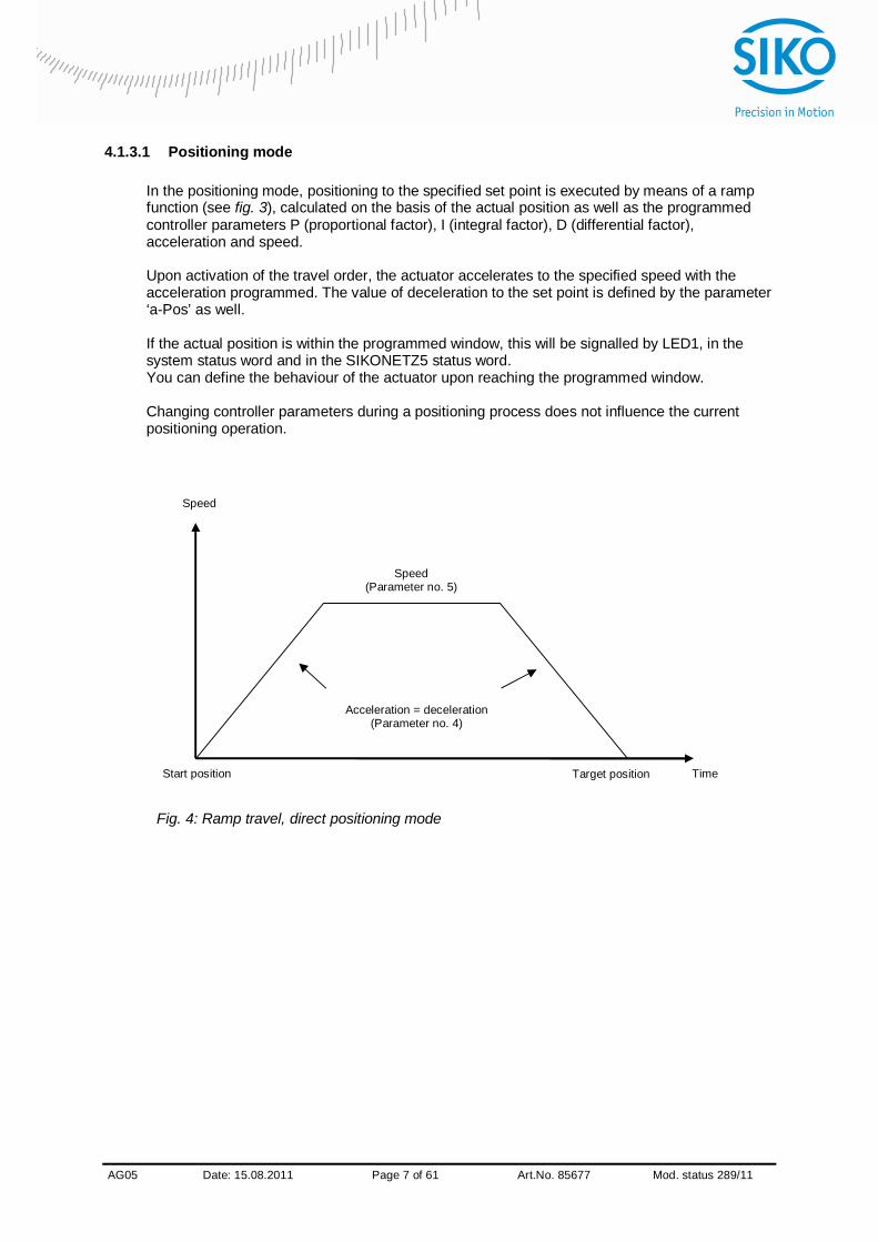
In the positioning mode, positioning to the specified set point is executed by means of a ramp function (see fig. 3), calculated on the basis of the actual position as well as the programmed controller parameters P (proportional factor), I (integral factor), D (differential factor), acceleration and speed. Upon activation of the travel order, the actuator accelerates to the specified speed with the acceleration programmed. The value of deceleration to the set point is defined by the parameter ‘a-Pos’ as well. If the actual position is within the programmed window, this will be signalled by LED1, in the system status word and in the SIKONETZ5 status word. You can define the behaviour of the actuator upon reaching the programmed window. Changing controller parameters during a positioning process does not influence the current positioning operation.
Fig. 4: Ramp travel, direct positioning mode
Start position Target position Time
Speed
Speed (Parameter no. 5)
Acceleration = deceleration (Parameter no. 4)

AG05
x Date: 15.08.2011 Page 8 of 61 Art.No. 85677 Mod. status 289/11
4.1.3.1.1 Loop positioning
If the actuator is operated on a spindle or an additional gear, the spindle or external gear backlash can be compensated by means of loop positioning. In this case, travelling to the target value is always from the same direction. This direction of approach can be defined. Example: The direction from which every target position shall be driven to is positive. Case 1 new position is greater than actual position:
Direct travel to the target position Case 2 new position is smaller than actual position:
The actuator drives beyond the target position by the loop length; afterwards, the set point is approached in positive direction.
Fig. 5: Positioning Loop+
Set point + -
Positioning in positive direction
Positioning in negative direction
Positioning: loop + Loop length

AG05
x Date: 15.08.2011 Page 9 of 61 Art.No. 85677 Mod. status 289/11
4.1.3.2 Inching operation
Inching operation is enabled in the ‘positioning mode’ only. You can program via parameters acceleration as well as speed in the inching mode.
NOTICE Ein Ausgleich der Spindelspieles (Schleifenpositionierung) erfolgt in dieser Betriebsart nicht
4.1.3.2.1 Inching mode 1 The drive travels once from the current actual position by the position ‘Delta Tipp’ depending on the mathematical sign of the value entered. ‘Delta Tipp‘ < 0: negative travel direction ‘Delta Tipp‘ > 0: positive travel direction
NOTICE If the ‘Spindle pitch’ parameter is programmed to zero, then the travelling way occurs by increments. If ‘Spindle pitch’ is unequal zero, then the information of the ‘Delta Tipp’ parameter refers to the travel distance in 1/100 mm.
Reaching of the target position will be signalled accordingly. The following conditions must be met for enabling the start of inching modes 1 and 2: The actuator must not be switched to error No active travel job Supply voltage of the output stage is applied
NOTICE If the actual position is outside the programmed limiting values, then travelling from this position in the respective direction is possible by means of inching mode 1 or 2!
4.1.3.2.2 Inching mode 2
The actuator travels from the current position as long as the relevant command is active. You can influence the inching speed via two parameters and it will be calculated in the actuator as illustrated in the example below:
v - Tipp (Parameter no. 9) = 10 rpm (can only be changed in the idle state)
Offset inching 2 (Parameter no. 30) = 85% (can be changed during inching operation)
The resulting inching speed in this example will be:
Inching speed = v - Tipp * Offset inching 2 = 10 rpm * 85% = 9 rpm
The results are always rounded to integers. The minimum speed is 1 rpm.
AG05
x Date: 15.08.2011 Page 10 of 61 Art.No. 85677 Mod. status 289/11
4.1.3.3 Rotational speed mode
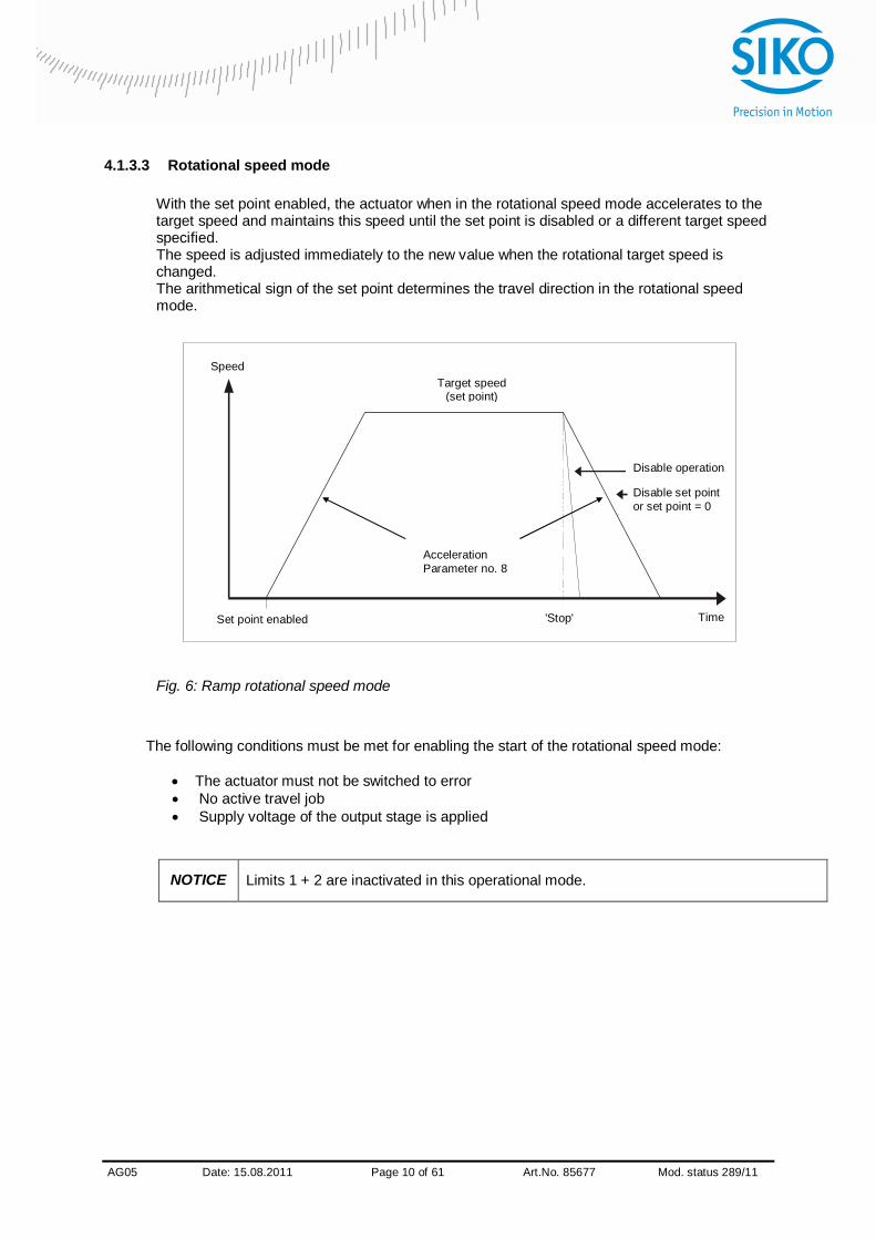
With the set point enabled, the actuator when in the rotational speed mode accelerates to the target speed and maintains this speed until the set point is disabled or a different target speed specified. The speed is adjusted immediately to the new value when the rotational target speed is changed. The arithmetical sign of the set point determines the travel direction in the rotational speed mode.
Fig. 6: Ramp rotational speed mode
The following conditions must be met for enabling the start of the rotational speed mode:
The actuator must not be switched to error No active travel job Supply voltage of the output stage is applied
NOTICE Limits 1 + 2 are inactivated in this operational mode.
Speed
Time
Target speed
(set point)
Acceleration Parameter no. 8
'Stop' Set point enabled
Disable set point or set point = 0
Disable operation

AG05
x Date: 15.08.2011 Page 11 of 61 Art.No. 85677 Mod. status 289/11
4.1.4 Current limiting
The actuator is equipped with adjustable current limiting, which serves primarily for protecting the actuator against overload. With the default value set, the nominal speed indicated on the product data sheet is achieved. Actuator overload results in limiting the motor current to the set value. As a consequence, the actuator cannot maintain the speed set, the contouring error increases. With the contouring error exceeding the contouring error limit the actuator will enter the state of error: contouring error.
NOTICE The actual motor current cannot be stated by measuring the supply current. With cycled output stages, the supply current does not correspond to the motor current. The actual motor current can be read out via the interface or indicated on the display.
4.2 Manual control (stand-alone operation)
4.2.1 Start inching mode 2
After applying supply voltage, the actuator will be on the uppermost level of the menu structure (default/delivery state). Positioning mode is active. Pressing the key starts left-hand motion (inching operation 2). Pressing the key starts right-hand motion (inching operation 2). Releasing the respective key stops travel movement. Pressing the key starts the parameterization/programming mode.

AG05
x Date: 15.08.2011 Page 12 of 61 Art.No. 85677 Mod. status 289/11
4.2.2 Specifying the set point and starting the travel order
4.2.2.1 Example: Starting positioning order to position 500 Preconditions: The display is at the uppermost level of the menu structure (basic state). Operating mode: Positioning mode Key functions: enabled
Initial state: normal display First press the key, then the key and hold down together.
The key enable time is counted down.
After expiry of the key enable time, the input field is released The first decimal place is active. Press the key twice to change the active decimal place.
The third decimal place is active. Press the key 5 times
Value 500 will be displayed. Confirm by pressing the key to start positioning.
4.2.2.2 Example: Starting positioning order to position -500
Preconditions: The display is at the uppermost level of the menu structure (basic state). Operating mode: Positioning mode Key functions: enabled
NOTICE For negative values to be entered, set first the value and only afterwards the arithmetical sign. The value 0 cannot be entered.
Initial state: normal display First press the key, then the key and hold down together.
The key enable time is counted down.
After expiry of the key enable time, the input field is released The first decimal place is active and blinks. Press the key twice to change the active decimal place.
The third decimal place is active and blinks. Press the key 5 times for entering the value.
Value 500 will be displayed. Press the key twice to change the active decimal place.
The fifth decimal place is active and blinks. Press the key 11 times for setting the arithmetical sign.
Value -500 will be displayed. Confirm by pressing the key to start positioning.

AG05
x Date: 15.08.2011 Page 13 of 61 Art.No. 85677 Mod. status 289/11
4.3 Menu selection
Fig. 7: Menu selection
Start
Hold down the key
Changeable parameters
Only readable parameters
Error memory
PIN – input required
key key
see menu only readable parameters
see menu error memory
Key enable time expired?
see menu changeable parameters
End
yes
no
AG05
x Date: 15.08.2011 Page 14 of 61 Art.No. 85677 Mod. status 289/11
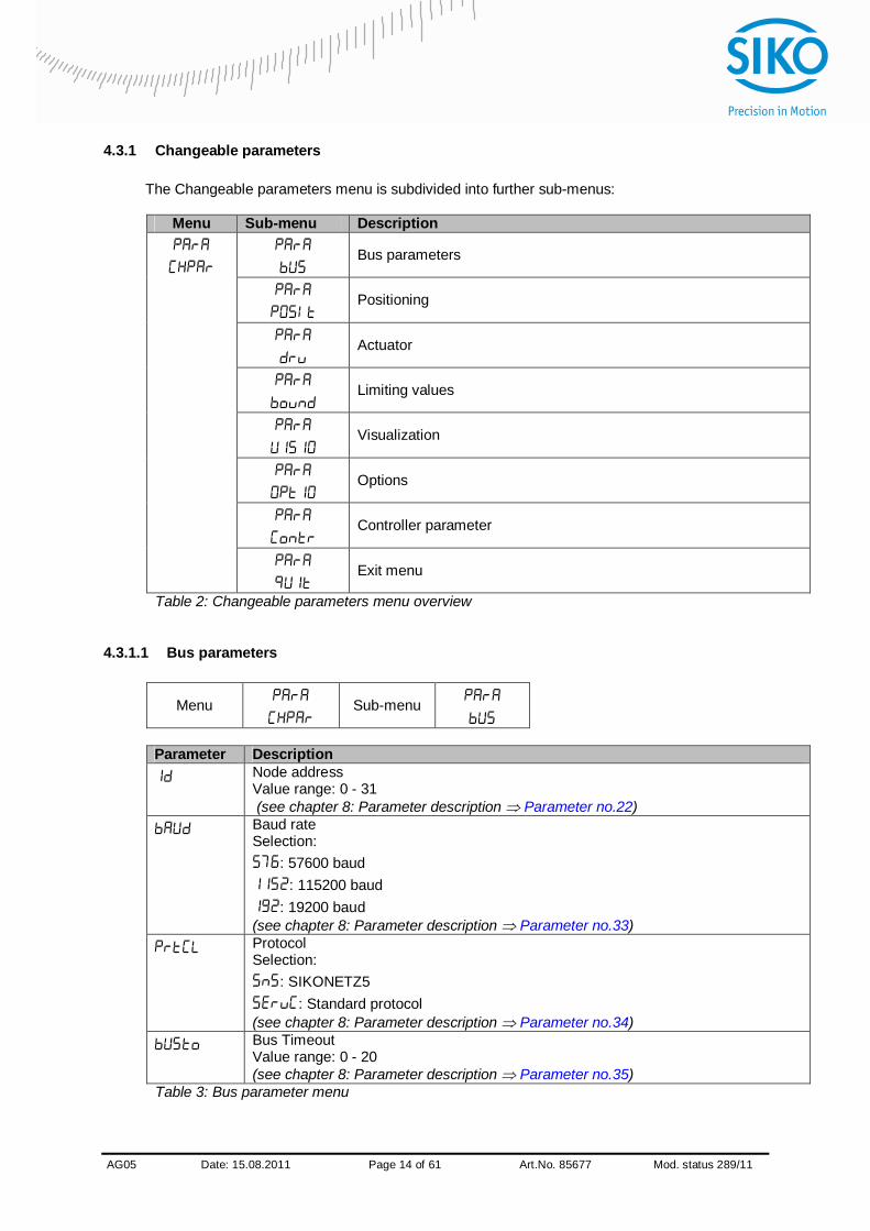
4.3.1 Changeable parameters
The Changeable parameters menu is subdivided into further sub-menus:
Menu Sub-menu Description
Bus parameters
Positioning
Actuator
Limiting values
Visualization
Options
Controller parameter
Exit menu
Table 2: Changeable parameters menu overview
4.3.1.1 Bus parameters
Menu
Sub-menu
Parameter Description
Node address Value range: 0 - 31 (see chapter 8: Parameter description Parameter no.22) Baud rate Selection:
: 57600 baud : 115200 baud
: 19200 baud (see chapter 8: Parameter description Parameter no.33) Protocol Selection:
: SIKONETZ5 : Standard protocol
(see chapter 8: Parameter description Parameter no.34) Bus Timeout Value range: 0 - 20 (see chapter 8: Parameter description Parameter no.35)
Table 3: Bus parameter menu
AG05
x Date: 15.08.2011 Page 15 of 61 Art.No. 85677 Mod. status 289/11
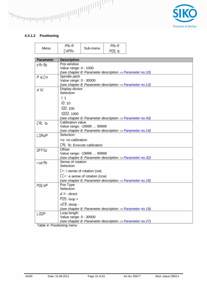
4.3.1.2 Positioning
Menu
Sub-menu
Parameter Description
Pos window Value range: 0 - 1000 (see chapter 8: Parameter description Parameter no.10) Spindle pitch Value range: 0 - 30000 (see chapter 8: Parameter description Parameter no.13) Display divisor Selection:
: 1 : 10
: 100 : 1000
(see chapter 8: Parameter description Parameter no.43) Calibration value Value range: -19999 … 99999 (see chapter 8: Parameter description Parameter no.14) Selection:
: no calibration : Execute calibration
Offset Value range: -19999 … 99999 (see chapter 8: Parameter description Parameter no.32) Sense of rotation Selection:
: i sense of rotation (cw) : e sense of rotation (ccw)
(see chapter 8: Parameter description Parameter no.18) Pos Type Selection:
: direct : loop + : sloop -
(see chapter 8: Parameter description Parameter no.19) Loop length Value range: 0 - 30000 (see chapter 8: Parameter description Parameter no.27)
Table 4: Positioning menu
AG05
x Date: 15.08.2011 Page 16 of 61 Art.No. 85677 Mod. status 289/11
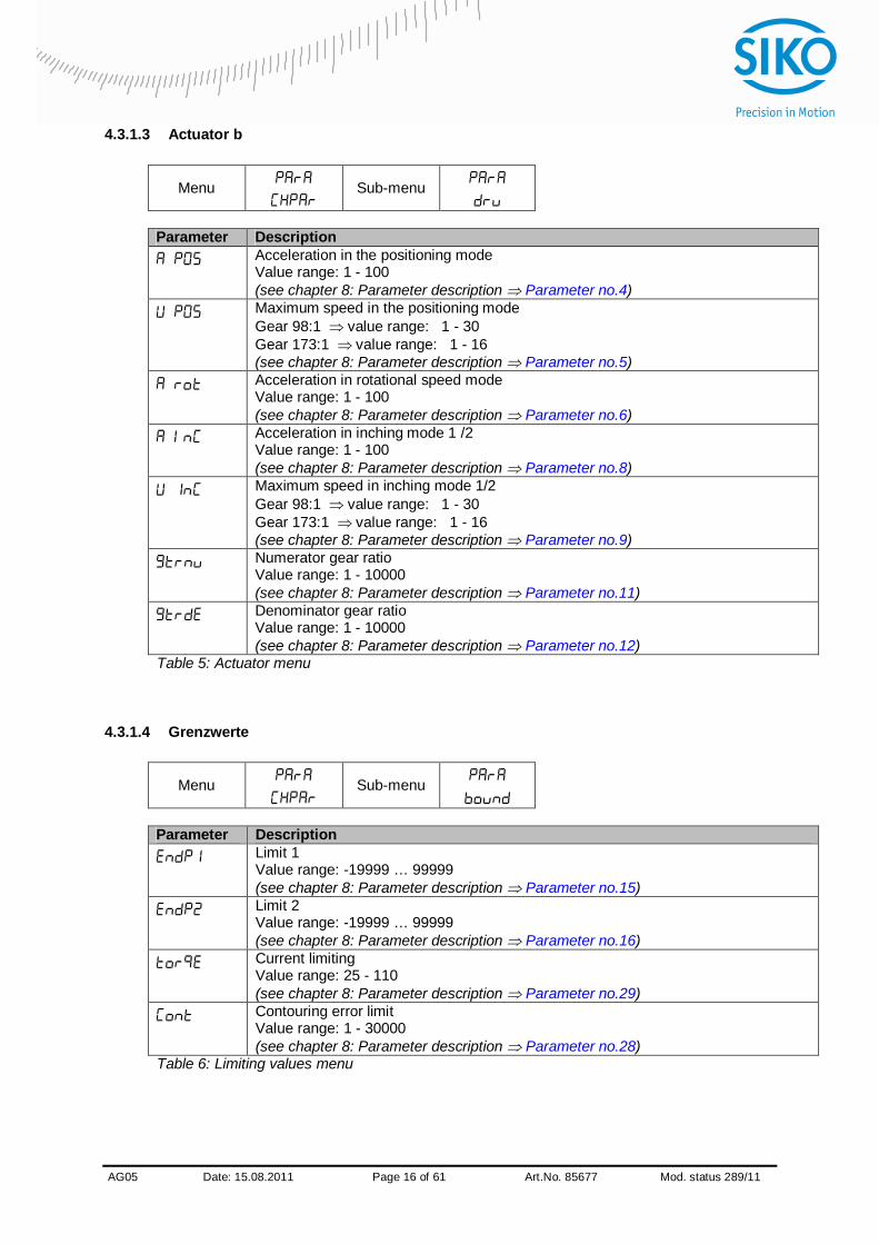
4.3.1.3 Actuator b
Menu
Sub-menu
Parameter Description
Acceleration in the positioning mode Value range: 1 - 100 (see chapter 8: Parameter description Parameter no.4) Maximum speed in the positioning mode Gear 98:1 value range: 1 - 30 Gear 173:1 value range: 1 - 16 (see chapter 8: Parameter description Parameter no.5) Acceleration in rotational speed mode Value range: 1 - 100 (see chapter 8: Parameter description Parameter no.6) Acceleration in inching mode 1 /2 Value range: 1 - 100 (see chapter 8: Parameter description Parameter no.8) Maximum speed in inching mode 1/2 Gear 98:1 value range: 1 - 30 Gear 173:1 value range: 1 - 16 (see chapter 8: Parameter description Parameter no.9) Numerator gear ratio Value range: 1 - 10000 (see chapter 8: Parameter description Parameter no.11) Denominator gear ratio Value range: 1 - 10000 (see chapter 8: Parameter description Parameter no.12)
Table 5: Actuator menu
4.3.1.4 Grenzwerte
Menu
Sub-menu
Parameter Description
Limit 1 Value range: -19999 … 99999 (see chapter 8: Parameter description Parameter no.15) Limit 2 Value range: -19999 … 99999 (see chapter 8: Parameter description Parameter no.16) Current limiting Value range: 25 - 110 (see chapter 8: Parameter description Parameter no.29) Contouring error limit Value range: 1 - 30000 (see chapter 8: Parameter description Parameter no.28)
Table 6: Limiting values menu

AG05
x Date: 15.08.2011 Page 17 of 61 Art.No. 85677 Mod. status 289/11
4.3.1.5 Visualization
Menu
Sub-menu
Parameter Description
Display orientation Selection:
: 0° : 180°
(see chapter 8: Parameter description Parameter no.45) LED 2 orange function Selection:
: Bus operation display : Off
(see chapter 8: Parameter description Parameter no.39) Red LED 1 function Selection:
: Indication of the operating status : Off
(see chapter 8: Parameter description Parameter no.40) Green LED 1 function Selection:
: Indication of the operating status : Off
(see chapter 8: Parameter description Parameter no.41) Decimal places Selection:
: 0 : 0.0
: 0.00 : 0.000
: 0.0000 (see chapter 8: Parameter description Parameter no.42) Direction indication function Selection:
: On : inverted
: Off (see chapter 8: Parameter description Parameter no.44)
AG05
x Date: 15.08.2011 Page 18 of 61 Art.No. 85677 Mod. status 289/11
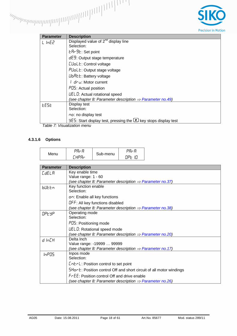
Parameter Description Displayed value of 2nd display line Selection:
: Set point : Output stage temperature
: Control voltage : Output stage voltage : Battery voltage : Motor current
: Actual position : Actual rotational speed
(see chapter 8: Parameter description Parameter no.49) Display test Selection:
: no display test : Start display test, pressing the key stops display test
Table 7: Visualization menu
4.3.1.6 Options
Menu
Sub-menu
Parameter Description
Key enable time Value range: 1 - 60 (see chapter 8: Parameter description Parameter no.37) Key function enable Selection:
: Enable all key functions : All key functions disabled
(see chapter 8: Parameter description Parameter no.38) Operating mode Selection:
: Positioning mode : Rotational speed mode
(see chapter 8: Parameter description Parameter no.20) Delta Inch Value range: -19999 … 99999 (see chapter 8: Parameter description Parameter no.17) Inpos mode Selection:
: Position control to set point : Position control Off and short circuit of all motor windings
: Position control Off and drive enable (see chapter 8: Parameter description Parameter no.26)
AG05
x Date: 15.08.2011 Page 19 of 61 Art.No. 85677 Mod. status 289/11
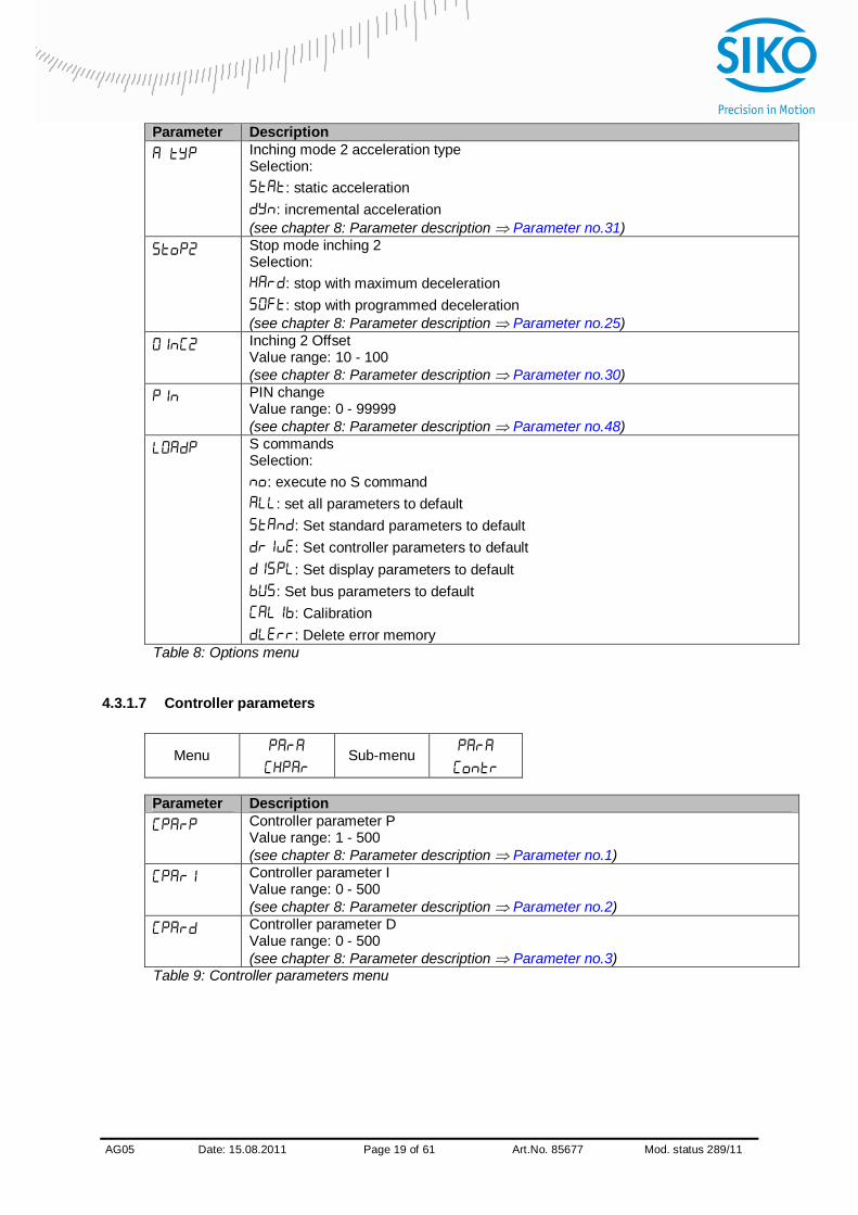
Parameter Description Inching mode 2 acceleration type Selection:
: static acceleration : incremental acceleration
(see chapter 8: Parameter description Parameter no.31) Stop mode inching 2 Selection:
: stop with maximum deceleration : stop with programmed deceleration
(see chapter 8: Parameter description Parameter no.25) Inching 2 Offset Value range: 10 - 100 (see chapter 8: Parameter description Parameter no.30) PIN change Value range: 0 - 99999 (see chapter 8: Parameter description Parameter no.48) S commands Selection:
: execute no S command : set all parameters to default
: Set standard parameters to default : Set controller parameters to default : Set display parameters to default
: Set bus parameters to default : Calibration : Delete error memory
Table 8: Options menu
4.3.1.7 Controller parameters
Menu
Sub-menu
Parameter Description
Controller parameter P Value range: 1 - 500 (see chapter 8: Parameter description Parameter no.1) Controller parameter I Value range: 0 - 500 (see chapter 8: Parameter description Parameter no.2) Controller parameter D Value range: 0 - 500 (see chapter 8: Parameter description Parameter no.3)
Table 9: Controller parameters menu
AG05
x Date: 15.08.2011 Page 20 of 61 Art.No. 85677 Mod. status 289/11
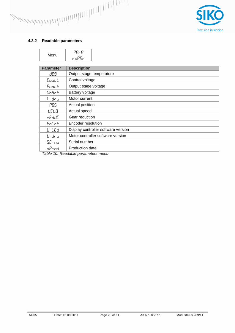
4.3.2 Readable parameters
Menu
Parameter Description
Output stage temperature Control voltage Output stage voltage Battery voltage Motor current Actual position Actual speed Gear reduction Encoder resolution Display controller software version Motor controller software version Serial number Production date
Table 10: Readable parameters menu

AG05
x Date: 15.08.2011 Page 21 of 61 Art.No. 85677 Mod. status 289/11
4.3.3 Error memory
Menu
Parameter Description
Number of errors in the error memory (see chapter 8: Parameter description Parameter no.61.
xxxxx Error 1 (see chapter 8: Parameter description Parameter no.62)
xxxxxError 2 (see chapter 8: Parameter description Parameter no.63)
xxxxxError 3 (see chapter 8: Parameter description Parameter no.64)
xxxxxError 4 (see chapter 8: Parameter description Parameter no.65)
xxxxxError 5 (see chapter 8: Parameter description Parameter no.66)
xxxxxError 6 (see chapter 8: Parameter description Parameter no.67)
xxxxxError 7 (see chapter 8: Parameter description Parameter no.68)
xxxxxError 8 (see chapter 8: Parameter description Parameter no.69)
xxxxxError 9 (see chapter 8: Parameter description Parameter no.70)
xxxxxError 10 (see chapter 8: Parameter description Parameter no.71)
Table 11: Error memory menu xxxxx = Plain text display of error codes (see chapter 7.2.1: Error codes)

AG05
x Date: 15.08.2011 Page 22 of 61 Art.No. 85677 Mod. status 289/11
5 Calibration Two steps are required for executing calibration: 1. Write the calibration value 2. Execute calibration Since the measuring system is an absolute system, calibration is necessary only once with commissioning. With calibration, the calibration value is adopted for calculation of the position value. The following equation is applied in case of calibration:
Position value = 0 + calibration value + offset value
Calibration value (see chapter 8: Parameter description Parameter no. 14) Offset value (see chapter 8: Parameter description Parameter no. 32)
NOTICE Calibration is only possible when no travel job is active!
6 External gear
If an external gear is used, a factor can be programmed via the parameters no. 11 ‘ü – numerator’ and parameter no. 12 ‘ü – denominator’ in order to include the gear ratio in position sensing.
Example (see fig. 7): The actuator is operated on a gear with transmission reduction of 5:1. For this purpose, the parameters ‘ü-numerator’ and ‘ü-denominator’ must be programmed as follows:
Parameter ‘ü – numerator’: 5 Parameter ‘ü – denominator’: 1
5 revolution 1 revolution
Gear output
external gear unit
5:1
M
internal drive
Fig. 8: External gear

AG05
x Date: 15.08.2011 Page 23 of 61 Art.No. 85677 Mod. status 289/11
Input of an odd gear transmission reduction value is possible according to the following example:
Transmission reduction = 3.78 Parameter ‘ü – numerator’: 378 Parameter ‘ü – denominator’: 100
7 Warnings / Errors
7.1 Warnings
Warnings do not influence the operation of the positioning drive. Warnings disappear after removing the cause. Possible warnings:
Battery voltage for absolute encoder is below limit exchange battery within the next 6 months.
Current limiting active.
7.2 Errors
Errors cause an immediate stop of the positioning drive. Error states are signalled via display. Via interface errors can also be detected: The error messages are entered in the error memory in the order of their detection. The last 10 error messages are displayed when the error memory is full. The cause of error can be tracked down with the help of the error codes.
AG05
x Date: 15.08.2011 Page 24 of 61 Art.No. 85677 Mod. status 289/11
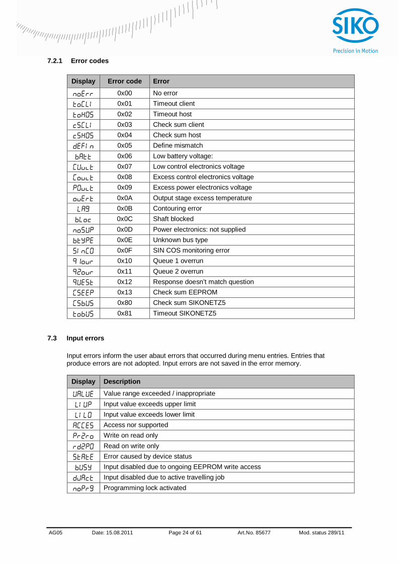
7.2.1 Error codes
Display Error code Error
0x00 No error 0x01 Timeout client 0x02 Timeout host 0x03 Check sum client 0x04 Check sum host 0x05 Define mismatch 0x06 Low battery voltage: 0x07 Low control electronics voltage 0x08 Excess control electronics voltage 0x09 Excess power electronics voltage 0x0A Output stage excess temperature 0x0B Contouring error 0x0C Shaft blocked 0x0D Power electronics: not supplied 0x0E Unknown bus type 0x0F SIN COS monitoring error 0x10 Queue 1 overrun 0x11 Queue 2 overrun 0x12 Response doesn’t match question 0x13 Check sum EEPROM 0x80 Check sum SIKONETZ5 0x81 Timeout SIKONETZ5
7.3 Input errors
Input errors inform the user abaut errors that occurred during menu entries. Entries that produce errors are not adopted. Input errors are not saved in the error memory.
Display Description
Value range exceeded / inappropriate Input value exceeds upper limit Input value exceeds lower limit Access nor supported Write on read only Read on write only Error caused by device status Input disabled due to ongoing EEPROM write access Input disabled due to active travelling job Programming lock activated

AG05
x Date: 15.08.2011 Page 25 of 61 Art.No. 85677 Mod. status 289/11
8 Parameter description Column Explanation
S “S” = Parameter transferred is saved in the device non-volatilely “-” = Parameter transferred is saved in the device volatilely
C
Parameter class 1 = Standard parameter 2 = Controller parameter 3 = Display parameter 4 = Bus parameter 5 = general parameter
No. Name Selection / value Default Description S C
1 Controller parameter
P
1 - 500 300 P gain of controller valid for all operating modes ( positioning mode, speed mode, inching mode )
S 2
2 Controller parameter
I
0 - 500 2 I gain of controller valid for all operating modes ( positioning mode, speed mode, inching mode )
S 2
3 Controller parameter
D
0 - 500 0 D gain of controller valid for all operating modes ( positioning mode, speed mode, inching mode )
S 2
4 a – pos 1 - 100 50 Acceleration in the positioning mode: values in % 100% correspond to: Gear 98:1 2.05 rps2
Gear 173:1 1.16 rps2
S 2
5 v - pos 1 - 30 1 - 16
10 Maximum speed in the positioning mode: values in rpm
gear 98:1 max. 30 rpm
gear 173:1 max. 16 rpm
S 2
6 a - rot 1 - 100 50 Acceleration in rotational speed mode values in % 100% correspond to: Gar 98:1 2.05 rps2
Gar 173:1 1.16 rps2
S 2
7 reserved 8 a - inch 1 - 100 50 Acceleration in inching mode 1 /2:
values in % 100% correspond to: Gear 98:1 2.05 rps2
Gear 173:1 1.16 rps2
S 2
9 v - inch 1 - 30 1 - 16
10 Maximum speed in inching mode 1 /2: values in revolutions/min
Gear 98:1 max. 30 rpm
Gear 173:1 max. 16 rpm
S 2

AG05
x Date: 15.08.2011 Page 26 of 61 Art.No. 85677 Mod. status 289/11
No. Name Selection / value Default Description S C
10 Pos window 0 - 1000 10 Operating mode: Positioning mode Positioning window If the actual position of the actuator is within the programmed set point ± this window, this is signalled by setting bit 3 in the status word of the actuator. Spindle pitch = 0: Values refer to increments Spindle pitch > 0: Values refer to travel distance in 1/100 mm Operating mode: Speed mode: If the actual rotational speed is within the target rotational speed ± this window, this is signalled by setting bit 3 in the system status word of the actuator.
S 1
11 ü - numerator 1 - 10000 1 Numerator gear ratio: a gear factor can be programmed here when a gear is used
S 1
12 ü - denominator
1 - 10000 1 Denominator gear ratio a gear factor can be programmed here when a gear is used
S 1
13 Spindle pitch 0 - 30000 0 Spindle pitch Spindle pitch parameter = 0: Position value is output in increments (720 increments per revolution of the driving shaft). Spindle pitch parameter > 0: (when operating the actuator on a spindle) The position value is output as travelling distance in 1/100 mm, not in increments. Input of target position is now in 1/100 mm as well, e. g. spindle with a pitch of 2 mm Spindle pitch parameter = 200.
S 1
14 Calibration value
-999999 to
999999
0 Calibration value Changes to the calibration value are adopted for calculation of the position value via S command only after calibration Position value = 0 + calibration value + offset value
S 1
15 Limit 1 -9999999 bis
9999999
99999 Operating mode: Positioning mode: Limit 1 Spindle pitch = 0: Values refer to increments Spindle pitch > 0: Values refer to travelling distance in 1/100 mm If actuator’s position is beyond the range defined by limit 1 and limit 2 (travel range), travelling will only be possible in inching mode in the direction of the travel range. Caution! ! Limit monitoring is deactivated if ‘limit 1’ is equal ‘limit 2’. Please note that there is a jump of the actual position if the resolution of the absolute encoder is exceeded! Operating mode: Speed mode: irrelevant
S 1

AG05
x Date: 15.08.2011 Page 27 of 61 Art.No. 85677 Mod. status 289/11
No. Name Selection / value Default Description S C
16 Limit 2 -9999999 to
9999999
-19999 Operating mode: Positioning mode: Limit 2 Spindle pitch = 0: Values refer to increments Spindle pitch > 0: Information refers to travel distance in 1/100 mm If actuator’s position is beyond the range defined by limit 1 and limit 2 (travel range), travelling will only be possible in inching mode in the direction of the travel range. Caution! ! Limit monitoring is deactivated if ‘limit 1’ is equal ‘limit 2’. Please note that there is a jump of the actual position if the resolution of the absolute encoder is exceeded! Operating mode: Speed mode: irrelevant
S 1
17 Delta inch -1000000 to
1000000
720 delta travelling distance with inching operation 1: indicates the relative travelling distance. positive value positive travelling direction negative value negative travelling direction Spindle pitch = 0: Values refer to increments Spindle pitch > 0: Information refers to travel distance in 1/100 mm
S 1
18 Sense of rotation
i,e i Counting direction of the measuring system: With shaft rotating counter-clockwise (view on the clamping ring of the actuator) i sense of rotation (cw): positive counting direction e sense of rotation (ccw): negative counting direction
S 1
19 Pos Type direct loop + sloop -
direct Operating mode: Positioning mode: Type of positioning direct: direct travelling from actual position to set point loop +: travelling to the set point occurs always in positive direction to compensate for spindle play loop -: travelling to the set point occurs always in negative direction to compensate for spindle play Caution! ! Loop positioning in positioning mode only Operating mode: Speed mode: irrelevant
S 1
20 Operating mode
positioning mode
/ speed mode
positioning
mode
Operating mode: Positioning mode (see chapter 4.1.3.1: Positioning mode) Operating mode: Speed mode: (see chapter 4.1.3.3: Speed mode)
S 1
21 reserved 22 Node
address 0 - 31 1 SIKONETZ5
Setting the SIKONETZ5 node address Parameter changes become active only after cold start or software reset. Standard protocol: no function
S 5

AG05
x Date: 15.08.2011 Page 28 of 61 Art.No. 85677 Mod. status 289/11
No. Name Selection / value Default Description S C
23 reserved 24 Set point see
Description column
0 Operating mode: Positioning mode indicates absolute target position. Spindle pitch = 0: Values refer to increments Spindle pitch > 0: Information refers to travel distance in 1/100 mm Value range: depends on the preprogrammed target values (parameters 15/16) Operating mode: Speed mode: indicates the target rotational speed in rpm Value range: Gear 98:1 max. 30 rpm Gear 173:1 max. 16 rpm
- 1
25 Stop mode Inch 2
0 - 1 0 Stop mode inching mode 2 / inching key operation Stopping behaviour of inching mode 2 or inching key mode, resp., can be parameterized differently. Stop mode = 0 stop with maximum deceleration Stop mode = 1 stop with programmed deceleration (parameter no. 8)
S 1
26 Inpos mode 0 - 2 0 Operating mode: Positioning mode With this parameter you can define the behaviour of the actuator upon reaching the position window: Inpos mode = 0 Position control to set point Inpos mode = 1 Position control OFF and short circuit of the motor windings Inpos mode = 2 Position control OFF and drive enable Operating mode: Speed mode: irrelevant
S 1
27 Loop length
0 - 30000 360 Operating mode: Positioning mode Spindle pitch = 0: Values refer to increments Spindle pitch > 0: values refer to travel distance in 1/100 mm Operating mode: Speed mode: irrelevant
S 1
28 Contouring error limit
1 - 30000 400 Contouring error limit: Exceeding the contouring error limit during on-going positioning results in a “Contouring error” fault.
S 1
29 Current limiting
25 - 110 110 Current limiting Limiting of surge current. Current limiting setup in % 100% = 1.1 A
S 1
30 Inching 2 Offset
10 - 100 100 Inching operation 2 The inching speed in Inching operation 2 can be influenced via this parameter Values in percentage of parameter no. 9
- 1

AG05
x Date: 15.08.2011 Page 29 of 61 Art.No. 85677 Mod. status 289/11
No. Name Selection / value Default Description S C
31 Type of acceleration
Inching mode 2
0 - 1 0 Inching operation 2 The type of acceleration can be set with this parameter. 0 = static acceleration Acceleration to final speed in one step as defined under parameter no. 8. 1 = incremental acceleration Acceleration to final speed as defined under parameter no. 8 with the following increments: 4 s to 20% of final speed 2 s to 50% of final speed 1 s to 100% of final speed
S 1
32 Offset -999999 to
999999
0 Offset value Changes to the offset value are immediately entered in the calculation of the position value. The following equation is applied in case of calibration: Position value = 0 + calibration value + offset value
S 1
33 Baud rate RS485
0 - 2 1 Baud rate of the RS485 interface 0 = 19200 1 = 57600 2 = 115200 Parameter changes become active only after cold start or software reset.
S 5
34 Protocol 0 - 1 0 Protocol of the RS485 interface 0 = SIKONETZ5 1 = Standard protocol Parameter changes become active only after cold start or software reset.
S 5
35 Bus Timeout 0 - 20 20 SIKONETZ5 Bus Timeout values in x100 ms Standard protocol: no function
S 4
36 Write reply parameter to set point
-
0 - 8 1 SIKONETZ5 This parameter defines the reply to the Write set point command 0 = Set point 1 = Actual value 2 = Output stage temperature 3 = Control voltage 4 = Output stage voltage 5 = Battery voltage 6 = Motor current: 7 = Actual position 8 = Actual rotational speed Standard protocol: no function
S 4
37 Key enable time
1 - 60 3 Display / key control Time in seconds the asterisk key must be held down until menu can be entered or the set point specification is enabled via display.
S 3

AG05
x Date: 15.08.2011 Page 30 of 61 Art.No. 85677 Mod. status 289/11
No. Name Selection / value Default Description S C
38 Key function enable
0 - 1 0
Display / key control The access to inching mode 2, positioning mode and rotational speed mode functions via keys can be set with this parameter. 0 = all functions via key enabled 1 = All functions via key disabled
S 3
39 LED 2 orange
0 - 1 1 LED 2 orange function 0 = Off 1 = Bus operation indication
S 3
40 LED 1 red 0 - 1 1 Red LED 1 function: 0 = Off 1 = Indication of the operating status
S 3
41 LED 1 green 0 - 1 1 Green LED 1 function: 0 = Off 1 = Indication of the operating status
S 3
42 Decimal places
0 - 4 0 Display: Input of decimal places 0 = 0 1 = 0.0 2 = 0.00 3 = 0.000 4 = 0.0000
S 3
43 Display divisor
0 - 3 0 Display: Divisor by which the display accuracy is reduced compared with the measurement resolution 0 = 1 1 = 10 2 = 100 3 = 1000
S 3
44 Direction indication function
0 - 2 0 Display: The direction indicators show the key to be pressed to arrive at the set position window . 0 = On 1 = Inverted 2 = Off
S 3
45 Display orientation
0 - 1 0 Display: Display orientation: 0 = 0° 1 = rotated by 180°
S 3
46 Programming mode
configuration
0 - 1 0 SIKONETZ5 0 = no programming mode 1 = apply programming mode Standard protocol: no function
S 5
47 Programming mode:
0 - 1 0 SIKONETZ5 0 = Programming mode Off 1 = Programming mode On Standard protocol: no function
- 1
48 PIN Change
0 - 99999 0 Display: Required PIN to be able to change parameters via keys and display
S 3

AG05
x Date: 15.08.2011 Page 31 of 61 Art.No. 85677 Mod. status 289/11
No. Name Selection / value Default Description S C
49 Displayed value
2nd display line
0 - 7 0 Display: Parameter to be displayed in the 2nd line of the display 0 = set point 1 = Output stage temperature 2 = Control voltage 3 = Output stage voltage 4 = Battery voltage 5 = Motor current: 6 = Actual position 7 = Actual rotational speed
S 3
50 Output stage temperature
Read only
- Output stage temperature: Values in 1/10 °C
- -
51 Voltage of control
Read only
- Control voltage Values in 1/10 V
- -
52 Voltage of output stage
Read only
- Output stage voltage: Values in 1/10 V
- -
53 Voltage of battery
Read only
- Battery voltage: Values in 1/100 V
- -
54 Motor current Read only
- Motor current: Values in mA
- -
55 Actual position
Read only
- Actual position: Spindle pitch = 0: values in increments Spindle pitch > 0: values in 1/100 mm
- -
56 Actual rotational
speed
Read only
- Actual rotational speed: Values in rpm
- -
57 Serial number
Read only
- Serial number S -
58 Production date
Read only
- Production date Format: DDMMYYYY
S -
59 Software version motor
controller
Read only
- Motor controller software version S -
60 Software- version display
controller
Read only
- Display controller software version
S -
61 Number of errors
Read only
- Number of errors in the error memory
S -
62 Error 1 Read only
- Error 1
S -
63 Error 2 Read only
- Error 2
S -
64 Error 3 Read only
- Error 3
S -
65 Error 4 Read only
- Error 4
S -
66 Error 5 Read only
- Error 5
S -
67 Error 6 Read only
- Error 6
S -
68 Error 7 Read only
- Error 7
S -

AG05
x Date: 15.08.2011 Page 32 of 61 Art.No. 85677 Mod. status 289/11
No. Name Selection / value Default Description S C
69 Error 8 Read only
- Error 8
S -
70 Error 9 Read only
- Error 9
S -
71 Error 10 Read only
- Error 10
S -
72 Gear reduction
Read only
- Gear reduction
S -
73 System Status Word
Read only
- System status word
- -
9 Standard Protocol
9.1 General
This user manual is valid with Motor controller firmware version V1.08! The PC sends a letter and additional parameters if required (ASCII). Subsequently, the AG05 sends a reply with a concluding <CR>. Parameters: 19200 / 57600 / 115200 baud, no parity, 8 data bits, 1 stop bit, no handshake
9.2 System Status Word
The system status word consists of 2 bytes and reflects the state of the actuator (see chapter 8: Parameter description Parameter no. 73).
High Byte Low Byte
Bit number 15 14 13 12 11 10 9 8 7 6 5 4 3 2 1 0 0 0 1 0 1 0 0 1 0 1 0 0 1 0 0 0
2 9 4 8 Fig. 1: Structure of system status word
Example (grey background): binary: 0010 1001 0100 1000 hex: 2 9 4 8
9.2.1 Meaning of the bits The table below informs about the meaning of the individual bits of the status word:
Bit State Description
Bit 0 ‘0‘ irrelevant Bit 1 ‘0‘ irrelevant Bit 2 ‘0‘ irrelevant Bit 3
‘1‘ ‘0‘
Operating mode: Positioning mode In Position Actual position is within the positioning window of the programmed set point. Actual position is beyond the positioning window of the programmed set point.

AG05
x Date: 15.08.2011 Page 33 of 61 Art.No. 85677 Mod. status 289/11
Bit State Description
‘1‘
‘0‘
Operating mode: Speed mode: In Position Actual rotational speed is within the specified tolerance window of the target speed Actual speed is outside the specified tolerance window.
Bit 4 ‘1‘ ‘0‘
Actuator travels: Actuator travels: Drive stands still (rotational speed < 2 rpm)
‘1‘
‘0‘
Operating mode: Positioning mode, upper limit: Actual position is above the programmed limiting value. Travelling is possible only in negative direction in inching mode. Actual position is below the programmed limiting value.
Bit 5
‘0‘ Operating mode: Speed mode: irrelevant
‘1‘
‘0‘
Operating mode: Positioning mode, lower limit: Actual position is below the programmed limiting value. Travelling is possible only in positive direction in inching mode. Actual position is above the programmed limiting value.
Bit 6
‘0‘ Operating mode: Speed mode: irrelevant Bit 7
‘1‘ ‘0‘
Driver state Motor is enabled Motor in control
Bit 8 ‘1‘
‘0‘
Error: Actuator has switched to error. The cause of the error must be removed and acknowledged. No error present
‘1‘ ‘0‘
Operating mode: Positioning mode: Loop travel If travel direction unequal start direction ( with loop travel ) If travel direction equal start direction
Bit 9
‘0‘ Operating mode: Speed mode: irrelevant Bit 10
‘1‘ ‘0‘
Output stage supply voltage No voltage, no travelling possible Voltage applied
Bit 11 ‘1‘ ‘0‘
Ready for travel: Not ready for travel Ready for travel: Actuator not in error state No active positioning Supply voltage of the output stage is applied Actual position within limits (only positioning mode)
Bit 12 ‘1‘ ‘0‘
Battery voltage: Battery voltage < 2,6 V Battery voltage OK
Bit 13 ‘1‘ ‘0‘
Current limiting Current limiting active Current limiting not active
‘1‘ ‘0‘
Operating mode: Positioning mode Status Positioning active in positioning mode. Positioning inactive.
Bit 14
‘1‘ ‘0‘
Operating mode: Speed mode: Status Enable target speed Target speed disabled:
Bit 15 ‘1‘
‘0‘
Contouring error: Contouring error the actuator cannot reach the pre-set speed due to too high load. The actuator switches the contouring error fault. Remedy: reduce programmed speed! No contouring error actual speed corresponds to target speed.
Table 12: System Status Word
AG05
x Date: 15.08.2011 Page 34 of 61 Art.No. 85677 Mod. status 289/11
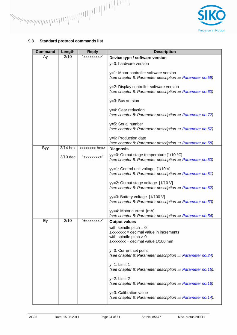
9.3 Standard protocol commands list
Command Length Reply Description Ay 2/10 "xxxxxxxx>" Device type / software version
y=0: hardware version y=1: Motor controller software version (see chapter 8: Parameter description Parameter no.59) y=2: Display controller software version (see chapter 8: Parameter description Parameter no.60) y=3: Bus version y=4: Gear reduction (see chapter 8: Parameter description Parameter no.72) y=5: Serial number (see chapter 8: Parameter description Parameter no.57) y=6: Production date (see chapter 8: Parameter description Parameter no.58)
Byy 3/14 hex
3/10 dec
xxxxxxxx hex>
"±xxxxxxx>"
Diagnosis yy=0: Output stage temperature [1/10 °C] (see chapter 8: Parameter description Parameter no.50) yy=1: Control unit voltage [1/10 V] (see chapter 8: Parameter description Parameter no.51) yy=2: Output stage voltage [1/10 V] (see chapter 8: Parameter description Parameter no.52) yy=3: Battery voltage [1/100 V] (see chapter 8: Parameter description Parameter no.53) yy=4: Motor current [mA] (see chapter 8: Parameter description Parameter no.54)
Ey 2/10 "±xxxxxxx>" Output values with spindle pitch = 0: ±xxxxxxx = decimal value in increments with spindle pitch > 0 ±xxxxxxx = decimal value 1/100 mm y=0: Current set point (see chapter 8: Parameter description Parameter no.24) y=1: Limit 1 (see chapter 8: Parameter description Parameter no.15). y=2: Limit 2 (see chapter 8: Parameter description Parameter no.16) y=3: Calibration value (see chapter 8: Parameter description Parameter no.14).
AG05
x Date: 15.08.2011 Page 35 of 61 Art.No. 85677 Mod. status 289/11
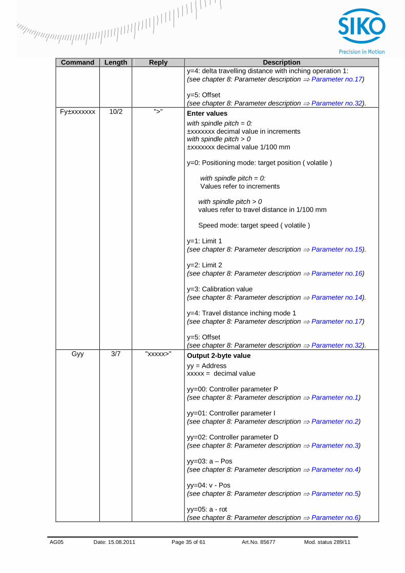
Command Length Reply Description y=4: delta travelling distance with inching operation 1: (see chapter 8: Parameter description Parameter no.17) y=5: Offset (see chapter 8: Parameter description Parameter no.32).
Fy±xxxxxxx 10/2 ">" Enter values with spindle pitch = 0: ±xxxxxxx decimal value in increments with spindle pitch > 0 ±xxxxxxx decimal value 1/100 mm y=0: Positioning mode: target position ( volatile ) with spindle pitch = 0: Values refer to increments with spindle pitch > 0 values refer to travel distance in 1/100 mm Speed mode: target speed ( volatile ) y=1: Limit 1 (see chapter 8: Parameter description Parameter no.15). y=2: Limit 2 (see chapter 8: Parameter description Parameter no.16) y=3: Calibration value (see chapter 8: Parameter description Parameter no.14). y=4: Travel distance inching mode 1 (see chapter 8: Parameter description Parameter no.17) y=5: Offset (see chapter 8: Parameter description Parameter no.32).
Gyy 3/7 "xxxxx>" Output 2-byte value yy = Address xxxxx = decimal value yy=00: Controller parameter P (see chapter 8: Parameter description Parameter no.1) yy=01: Controller parameter I (see chapter 8: Parameter description Parameter no.2) yy=02: Controller parameter D (see chapter 8: Parameter description Parameter no.3) yy=03: a – Pos (see chapter 8: Parameter description Parameter no.4) yy=04: v - Pos (see chapter 8: Parameter description Parameter no.5) yy=05: a - rot (see chapter 8: Parameter description Parameter no.6)

AG05
x Date: 15.08.2011 Page 36 of 61 Art.No. 85677 Mod. status 289/11
Command Length Reply Description yy=06: reserved yy=07: a - inch (see chapter 8: Parameter description Parameter no.8) yy=08: v - inch (see chapter 8: Parameter description Parameter no.9) yy=09: Pos window Spindle pitch = 0 -> increments spindle pitch > 0 -> 1/100 mm (see chapter 8: Parameter description Parameter no.10). yy=10: ü - numerator (see chapter 8: Parameter description Parameter no.11) yy=11: ü - denominator (see chapter 8: Parameter description Parameter no.12. yy=12: reserved yy=13: Spindle pitch in 1/100 m (see chapter 8: Parameter description Parameter no.13). yy=14: Node address (see chapter 8: Parameter description Parameter no.22) yy=15: Stop mode inching 2 0 = Hard Stop 1 = Soft Stop (see chapter 8: Parameter description Parameter no.25) yy=16: Inpos mode 0 = position control 1 = Emf brake 2 = Enable (see chapter 8: Parameter description Parameter no.26) yy=17: Loop length Spindle pitch = 0 -> increments spindle pitch > 0 -> 1/100 mm (see chapter 8: Parameter description Parameter no.27). yy=18: Contouring error limit (see chapter 8: Parameter description Parameter no.28) yy=19: reserved yy=20: reserved yy=21: reserved yy=22: reserved yy=23: reserved

AG05
x Date: 15.08.2011 Page 37 of 61 Art.No. 85677 Mod. status 289/11
Command Length Reply Description yy=24: Current limiting [%] Range 25 – 110 % of nominal torque (see chapter 8: Parameter description Parameter no.29) yy=25: Baud rate RS485 0 = 19200 1 = 57600 2 = 115200 (see chapter 8: Parameter description Parameter no.33). yy=26: Bus Timeout Range 0 - 20 x100 ms (see chapter 8: Parameter description Parameter no.35). yy=27: Inching 2 Offset Range 10 – 100% of inching speed (see chapter 8: Parameter description Parameter no.30) yy=28: Key function enable 0 = all functions via key enabled 1 = All functions via key disabled (see chapter 8: Parameter description Parameter no.38) yy=29: Key enable time Range 1 – 60 seconds (see chapter 8: Parameter description Parameter no.37) yy=30: Display orientation 0 = 0° 1 = rotated by 180° (see chapter 8: Parameter description Parameter no.45) yy=31: Display divisor 0 = 1 1 = 10 2 = 100 3 = 1000 (see chapter 8: Parameter description Parameter no.43). yy=32: Decimal places 0 = 0 1 = 0.0 2 = 0.00 3 = 0.000 4 = 0.0000 (see chapter 8: Parameter description Parameter no.42) yy=33: Direction indication function 0 = On 1 = inverted 2 = Off (see chapter 8: Parameter description Parameter no.44) yy=34: Encoder resolution (see chapter 8: Parameter description Parameter no.72) yy=35: reserved

AG05
x Date: 15.08.2011 Page 38 of 61 Art.No. 85677 Mod. status 289/11
Command Length Reply Description yy=36: LED 2 orange 0 = Off 1 = On (see chapter 8: Parameter description Parameter no.39) yy=37: LED1 red 0 = Off 1 = On (see chapter 8: Parameter description Parameter no.40) yy=38: LED 1 green 0 = Off 1 = On (see chapter 8: Parameter description Parameter no.41) yy=39: Inching mode 2 acceleration type 0 = static acceleration 1 = incremental acceleration (see chapter 8: Parameter description Parameter no.31) yy=40: Protocol 0 = SIKONETZ5 1 = Standard protocol (see chapter 8: Parameter description Parameter no.34). yy=41: PIN change (see chapter 8: Parameter description Parameter no.48) yy=42: Temporary key function enable 0 = Access as defined under Key function enable 1 = Access inverted as defined under Key function enable yy=43: Displayed value of 2nd display line 0 = Set point 1 = Output stage temperature 2 = Control voltage 3 = Output stage voltage 4 = Battery voltage 5 = Motor current: 6 = Actual position 7 = Actual rotational speed (see chapter 8: Parameter description Parameter no.49)
Hyyxxxxx 8/2 ">" Enter 2-byte value yy = address xxxxx = decimal value yy=00: Controller parameter P (see chapter 8: Parameter description Parameter no.1) yy=01: Controller parameter I (see chapter 8: Parameter description Parameter no.2) yy=02: Controller parameter D (see chapter 8: Parameter description Parameter no.3)

AG05
x Date: 15.08.2011 Page 39 of 61 Art.No. 85677 Mod. status 289/11
Command Length Reply Description yy=03: a – Pos (see chapter 8: Parameter description Parameter no.4) yy=04: v - Pos (see chapter 8: Parameter description Parameter no.5) yy=05: a - Rot (see chapter 8: Parameter description Parameter no.6) yy=06: reserved yy=07: a - Inch (see chapter 8: Parameter description Parameter no.8) yy=08: v - Inch (see chapter 8: Parameter description Parameter no.9) yy=09: Enter positioning window Spindle pitch = 0 -> increments spindle pitch > 0 -> 1/100 mm (see chapter 8: Parameter description Parameter no.10). yy=10: ü - numerator (see chapter 8: Parameter description Parameter no.11) yy=11: ü - denominator (see chapter 8: Parameter description Parameter no.12. yy=12: reserved yy=13: Enter spindle pitch in 1/100 m (see chapter 8: Parameter description Parameter no.13). yy=14: Node address (see chapter 8: Parameter description Parameter no.22) yy=15: Stop mode inching 2 (see chapter 8: Parameter description Parameter no.25) yy=16: Inpos mode (see chapter 8: Parameter description Parameter no.26) yy=17: Loop length Spindle pitch = 0 -> increments spindle pitch > 0 -> 1/100 mm (see chapter 8: Parameter description Parameter no.27). yy=18: Contouring error limit (see chapter 8: Parameter description Parameter no.28) yy=19: reserved yy=20: reserved yy=21: reserved yy=22: reserved

AG05
x Date: 15.08.2011 Page 40 of 61 Art.No. 85677 Mod. status 289/11
Command Length Reply Description yy=23: reserved yy=24: Current limiting [%] (see chapter 8: Parameter description Parameter no.29) yy=25: Baud rate RS485 (see chapter 8: Parameter description Parameter no.33). yy=26: Bus Timeout (see chapter 8: Parameter description Parameter no.35). yy=27: Inching 2 Offset (see chapter 8: Parameter description Parameter no.30) yy=28: Key function enable 0 = all functions via key enabled 1 = all functions via key disabled (see chapter 8: Parameter description Parameter no.38) yy=29: Key enable time (see chapter 8: Parameter description Parameter no.37) yy=30: Display orientation (see chapter 8: Parameter description Parameter no.45) yy=31: Display divisor (see chapter 8: Parameter description Parameter no.43). yy=32: Display: Decimal places (see chapter 8: Parameter description Parameter no.42) yy=33: Display: Direction indication function (see chapter 8: Parameter description Parameter no.44) yy=34: reserved yy=35: reserved yy=36: LED 2 orange 0 = Off 1 = On (see chapter 8: Parameter description Parameter no.39) yy=37: Red LED 1 0 = Off 1 = On (see chapter 8: Parameter description Parameter no.40) yy=38: Green LED 1 0 = Off 1 = On (see chapter 8: Parameter description Parameter no.41) yy=39: Inching mode 2 acceleration type 0 = constant acceleration to final speed value 1 = incremental acceleration to final speed value (see chapter 8: Parameter description Parameter no.31)

AG05
x Date: 15.08.2011 Page 41 of 61 Art.No. 85677 Mod. status 289/11
Command Length Reply Description yy=40: Protocol 0 = SIKONETZ5 1 = Standard protocol (see chapter 8: Parameter description Parameter no.34). yy=41: PIN change (see chapter 8: Parameter description Parameter no.48) yy=42: Temporary key function enable 0 = Access as defined under Key function enable 1 = Access inverted as defined under Key function enable yy=43: Displayed value of 2nd display line 0 = Set point 1 = Output stage temperature 2 = Control voltage 3 = Output stage voltage 4 = Battery voltage 5 = Motor current: 6 = Actual position 7 = Actual rotational speed (see chapter 8: Parameter description Parameter no.49)
I 1/2 ">" Cancel current travel job in positioning mode Motor remains in control state
Jyy 2/4
"0xhh" Read out error memory yy = 00 number of errors in the error memory (see chapter 8: Parameter description Parameter no.61. yy = 01 Error 1 (see chapter 8: Parameter description Parameter no.62) yy = 02 Error 2 (see chapter 8: Parameter description Parameter no.63) yy = 03 Error 3 (see chapter 8: Parameter description Parameter no.64) yy = 04 Error 4 (see chapter 8: Parameter description Parameter no.65) yy = 05 Error 5 (see chapter 8: Parameter description Parameter no.66) yy = 06 Error 6 (see chapter 8: Parameter description Parameter no.67) yy = 07 Error 7 (see chapter 8: Parameter description Parameter no.68) yy = 08 Error 8 (see chapter 8: Parameter description Parameter no.69) yy = 09 Error 9 (see chapter 8: Parameter description Parameter no.70)
AG05
x Date: 15.08.2011 Page 42 of 61 Art.No. 85677 Mod. status 289/11
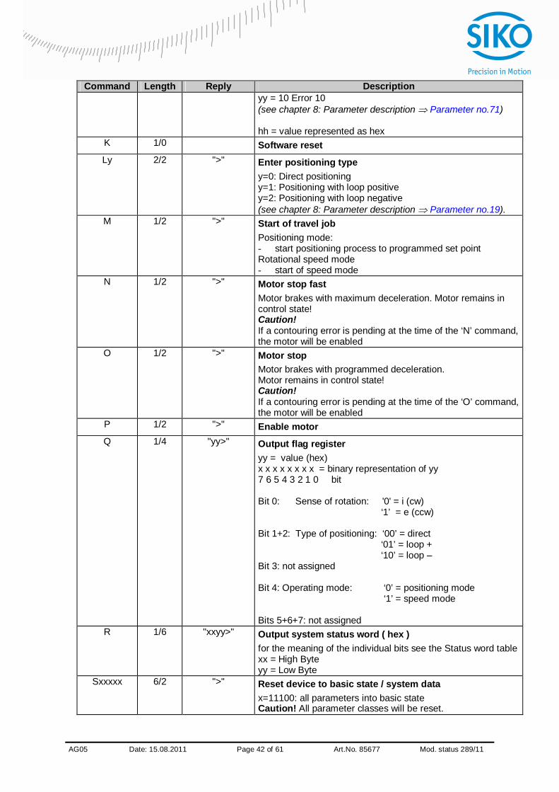
Command Length Reply Description yy = 10 Error 10 (see chapter 8: Parameter description Parameter no.71) hh = value represented as hex
K 1/0 Software reset Ly 2/2 ">" Enter positioning type
y=0: Direct positioning y=1: Positioning with loop positive y=2: Positioning with loop negative (see chapter 8: Parameter description Parameter no.19).
M 1/2 ">" Start of travel job Positioning mode: - start positioning process to programmed set point Rotational speed mode - start of speed mode
N 1/2 ">" Motor stop fast Motor brakes with maximum deceleration. Motor remains in control state! Caution! If a contouring error is pending at the time of the ‘N’ command, the motor will be enabled
O 1/2 ">" Motor stop Motor brakes with programmed deceleration. Motor remains in control state! Caution! If a contouring error is pending at the time of the ‘O’ command, the motor will be enabled
P 1/2 ">" Enable motor Q 1/4 "yy>" Output flag register
yy = value (hex) x x x x x x x x = binary representation of yy 7 6 5 4 3 2 1 0 bit Bit 0: Sense of rotation: '0' = i (cw) ‘1’ = e (ccw) Bit 1+2: Type of positioning: ‘00’ = direct ‘01’ = loop + ‘10’ = loop – Bit 3: not assigned Bit 4: Operating mode: ‘0’ = positioning mode ‘1’ = speed mode Bits 5+6+7: not assigned
R 1/6 "xxyy>" Output system status word ( hex ) for the meaning of the individual bits see the Status word table xx = High Byte yy = Low Byte
Sxxxxx
6/2
">"
Reset device to basic state / system data x=11100: all parameters into basic state Caution! All parameter classes will be reset.

AG05
x Date: 15.08.2011 Page 43 of 61 Art.No. 85677 Mod. status 289/11
Command Length Reply Description After restart, the factory settings will be active, this applies to protocol and baud rate as well. x=11101: only standard parameters into basic state x=11102: only controller parameters into basic state x=11003: only display parameters into basic state x=11103: reset error x=11104: calibrate AG05 x=11105: delete primary error memory
Ty 2/2 ">" Enter sense of rotation y=0: i sense of rotation (cw) y=1: e sense of rotation (ccw) (see chapter 8: Parameter description Parameter no.18).
V 1/6 "±xxx>" Output actual rotational speed Unit rpm (see chapter 8: Parameter description Parameter no.56)
W 1/4 "xxxx" Binary position value xxxx = 4 bytes in 2-complement MSB…LSB (see chapter 8: Parameter description Parameter no.55)
Xy 2/2 ">" Enter operation mode y=0 Positioning mode: y=1 Speed mode: (see chapter 8: Parameter description Parameter no.20)
Y 1/2 ">" Start of inching mode 1 (only in positioning mode) Z 1/10 "±xxxxxxx>" Output position value
(see chapter 8: Parameter description Parameter no.55) , (2Chex) 1/0 Travelling in inching mode 2 positive
Actuator travels in positive direction as long as ‘,’ sign is permanently sent (only in positioning mode).
. (2E hex) 1/0 Travelling in inching mode 2 negative Actuator travels in negative direction as long as ‘,’ sign is permanently sent (only in positioning mode).
9.4 Error number encoding
Code Description ?01 Input of illegal parameter number ?02 Illegal value range: ?03 No authorization ( active control via Profibus/CAN-Bus) ?04 Input disabled due to operating state ?07 Upper software limit exceeded ?08 Lower software limit exceeded ?09 Set point entered exceeds limiting value ?10 Error ?11 EEPROM write access active ?12 Set point < range limit ?13 Set point > range limit
AG05
x Date: 15.08.2011 Page 44 of 61 Art.No. 85677 Mod. status 289/11
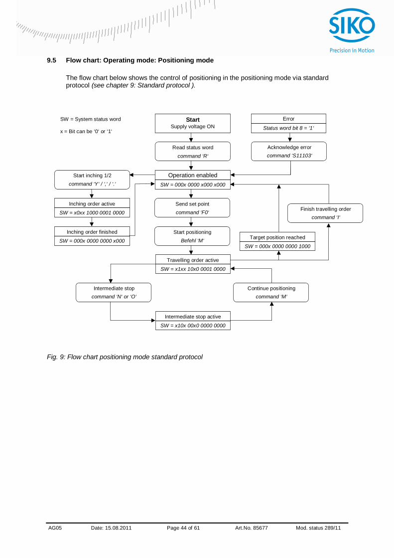
9.5 Flow chart: Operating mode: Positioning mode The flow chart below shows the control of positioning in the positioning mode via standard protocol (see chapter 9: Standard protocol ).
Fig. 9: Flow chart positioning mode standard protocol
Acknowledge error command ‘S11103‘
Start Supply voltage ON
Read status word command ‘R‘
Operation enabled SW = 000x 0000 x000 x000
Send set point command ‘F0‘
Start positioning Befehl ‘M‘
Travelling order active
SW = x1xx 10x0 0001 0000
Continue positioning command ‘M‘
Error
Status word bit 8 = ‘1‘
Intermediate stop active
SW = x10x 00x0 0000 0000
Intermediate stop command ‘N‘ or ‘O‘
Start inching 1/2 command ‘Y‘ / ‘,‘ / ‘.‘
Inching order active
SW = x0xx 1000 0001 0000
Inching order finished
SW = 000x 0000 0000 x000
SW = System status word x = Bit can be ‘0‘ or ‘1‘
Target position reached
SW = 000x 0000 0000 1000
Finish travelling order command ‘I‘
AG05
x Date: 15.08.2011 Page 45 of 61 Art.No. 85677 Mod. status 289/11
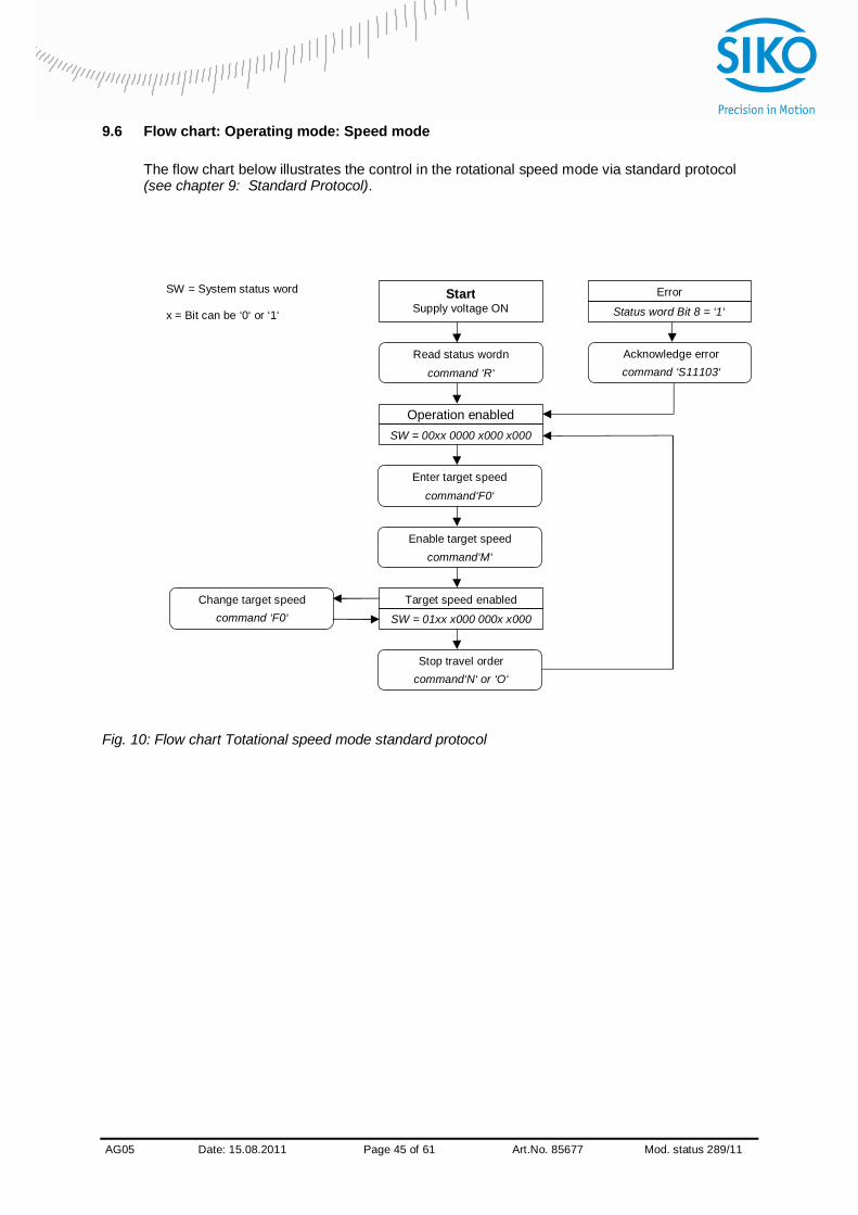
9.6 Flow chart: Operating mode: Speed mode
The flow chart below illustrates the control in the rotational speed mode via standard protocol (see chapter 9: Standard Protocol).
Fig. 10: Flow chart Totational speed mode standard protocol
Acknowledge error command ‘S11103‘
Start Supply voltage ON
Read status wordn command ‘R‘
Operation enabled SW = 00xx 0000 x000 x000
Enter target speed command‘F0‘
Enable target speed command‘M‘
Target speed enabled
SW = 01xx x000 000x x000
Stop travel order command‘N‘ or ‘O‘
Change target speed command ‘F0‘
Error
Status word Bit 8 = ‘1‘
SW = System status word x = Bit can be ‘0‘ or ‘1‘
AG05
x Date: 15.08.2011 Page 46 of 61 Art.No. 85677 Mod. status 289/11
10 Communication via SIKONETZ5
10.1 Interface
RS485 interface Available baud rates: 19,2 Kbit / 57,6 Kbit / 115,2 Kbit No parity, 8 data bits, 1 stop bit, no handshake
10.2 Data exchange
The protocol functions according to the master – slave principle. The actuator acts as a slave. Every instance of communication must be initiated by the master. When the master has sent a command telegram, the slave sends a reply telegram. Broadcast commands are an exception, they remain always unanswered by the slave. the protocol is optimized for cyclical data exchange. The relevant data such as set point and actual value can be transferred between master and slave by a single telegram exchange. The parameter to be returned by the slave as a reply to the master’s Write set point command can be defined via the “Write set point reply parameter”.
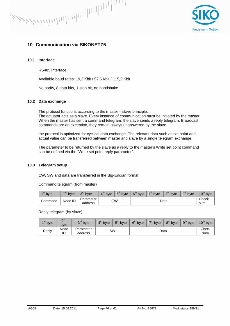
10.3 Telegram setup
CW, SW and data are transferred in the Big-Endian format. Command telegram (from master)
1st byte 2nd byte 3rd byte 4th byte 5th byte 6th byte 7th byte 8th byte 9th byte 10th byte
Command Node ID Parameter address CW Data Check
sum Reply telegram (by slave)
1st byte 2nd
byte 3rd byte 4th byte 5th byte 6th byte 7th byte 8th byte 9th byte 10th byte
Reply Node ID
Parameter address SW Data Check
sum
AG05
x Date: 15.08.2011 Page 47 of 61 Art.No. 85677 Mod. status 289/11
10.3.1 Command
0x00 = read 0x01 = write 0x02 = broadcast
10.3.2 Node ID
Node address (see chapter 8: Parameter description Parameter no. 22)
10.3.3 Parameter address
Description, see chapter 10.10: Parameterization via SIKONETZ5.
10.3.4 Control word
Control word (CW) master to slave.
10.3.5 Status word
Status word (SW) slave to master.
10.3.6 Data
Range for data exchange. Size: 4 bytes.
10.3.7 Check sum
For checking error-free data transfer, a check sum is formed at the end of the telegram. The check sum is the exclusive-OR-link of bytes 1 – 9. Check sum [Byte10] = [Byte1] XOR [Byte2] XOR [Byte3] XOR [Byte4] XOR [Byte5] XOR [Byte6] XOR [Byte7] XOR [Byte8] XOR [Byte9] The following applies for checking the telegram received: [Byte1] XOR [Byte2] XOR [Byte3] XOR [Byte4] XOR [Byte5] XOR [Byte6] XOR [Byte7] XOR [Byte8] XOR [Byte9] XOR [Byte 10] = 0 With a result unequal 0 a transmission error is to be assumed.
10.4 Synchronization
Byte/telegram synchronization is via “Timeout”. The intervals between the individual bytes of a telegram must not exceed the value of 10 ms. If an addressed device does not respond, the master must not send another telegram earlier than after 30 ms.
AG05
x Date: 15.08.2011 Page 48 of 61 Art.No. 85677 Mod. status 289/11
10.5 Bus Timeout
The first telegram received by the slave starts time monitoring. Every new telegram recognized as valid by the slave (correct check sum) triggers time monitoring. If timeout occurs during an active travel job, this will result in the Timeout error, i. e. the current travel job is cancelled. Thus, a broken cable can be detected for instance and the actuator set into a defined state. For this purpose the master must address all slaves cyclically.
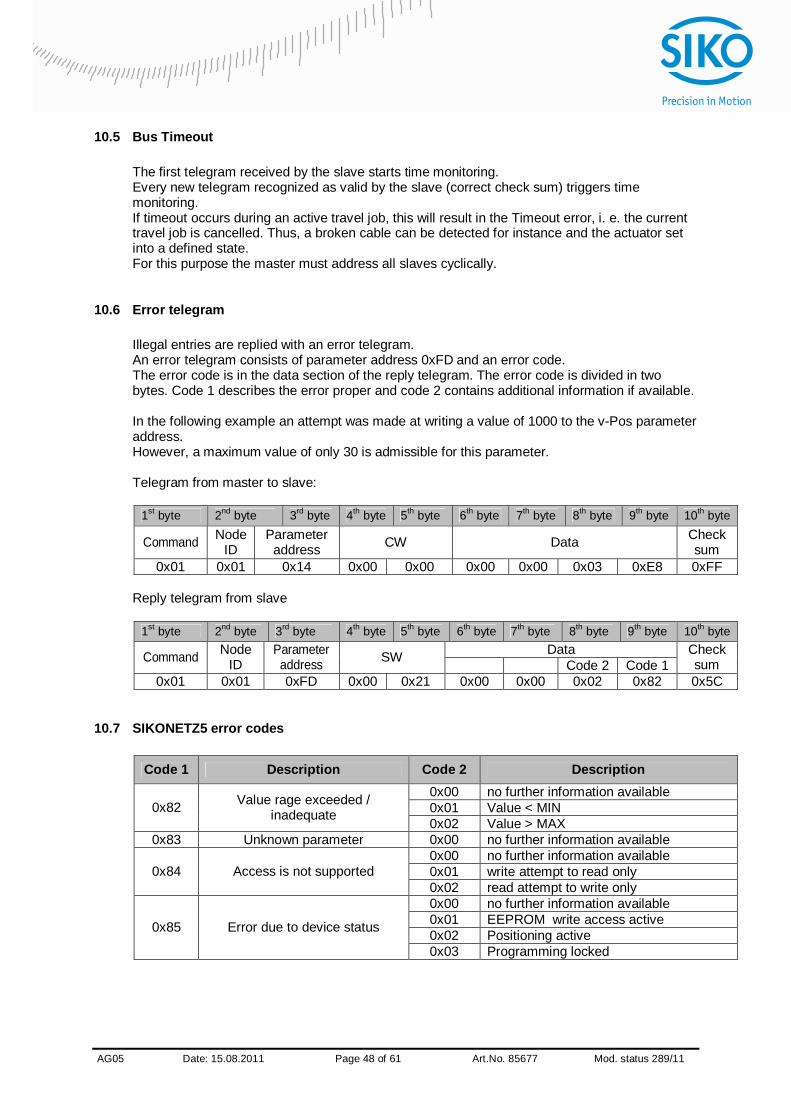
10.6 Error telegram
Illegal entries are replied with an error telegram. An error telegram consists of parameter address 0xFD and an error code. The error code is in the data section of the reply telegram. The error code is divided in two bytes. Code 1 describes the error proper and code 2 contains additional information if available. In the following example an attempt was made at writing a value of 1000 to the v-Pos parameter address. However, a maximum value of only 30 is admissible for this parameter. Telegram from master to slave:
1st byte 2nd byte 3rd byte 4th byte 5th byte 6th byte 7th byte 8th byte 9th byte 10th byte
Command Node ID
Parameter address CW Data Check
sum 0x01 0x01 0x14 0x00 0x00 0x00 0x00 0x03 0xE8 0xFF
Reply telegram from slave
1st byte 2nd byte 3rd byte 4th byte 5th byte 6th byte 7th byte 8th byte 9th byte 10th byte
Data Command Node ID
Parameter address SW Code 2 Code 1
Check sum
0x01 0x01 0xFD 0x00 0x21 0x00 0x00 0x02 0x82 0x5C
10.7 SIKONETZ5 error codes
Code 1 Description Code 2 Description 0x00 no further information available 0x01 Value < MIN 0x82 Value rage exceeded /
inadequate 0x02 Value > MAX 0x83 Unknown parameter 0x00 no further information available
0x00 no further information available 0x01 write attempt to read only 0x84 Access is not supported 0x02 read attempt to write only 0x00 no further information available 0x01 EEPROM write access active 0x02 Positioning active 0x85 Error due to device status
0x03 Programming locked
AG05
x Date: 15.08.2011 Page 49 of 61 Art.No. 85677 Mod. status 289/11
10.8 Functional description of the control units
10.9 Errors
If a slave is in the error state the slave signals this state with SW.7 = 1. Errors must be acknowledged by CW.5 = 0/1. If the cause of the error has not ben resolved at the time of acknowledgement, the error will not be reset. After acknowledgement of an error, the slave is in the switch-lock state. The switch-lock can be released via a negative flank on CW.0 or CW.1 or CW.2. Errors are stored in the error memory and can be read out. In order to receive the last error occurring the number of errors must first be read in parameter address 0x80. With 0x80 + number of errors the parameter address with the latest error is received. Under this address the error code is found (see chapter 7.2.1: Error codes).
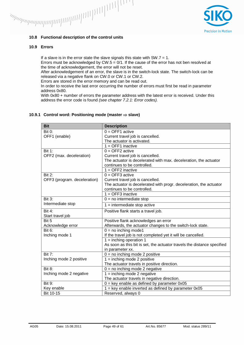
10.9.1 Control word: Positioning mode (master slave)
Bit Description 0 = OFF1 active Current travel job is cancelled. The actuator is activated.
Bit 0: OFF1 (enable)
1 = OFF1 inactive 0 = OFF2 active Current travel job is cancelled. The actuator is decelerated with max. deceleration, the actuator continues to be controlled.
Bit 1: OFF2 (max. deceleration)
1 = OFF2 inactive 0 = OFF3 active Current travel job is cancelled. The actuator is decelerated with progr. deceleration, the actuator continues to be controlled.
Bit 2: OFF3 (program. deceleration)
1 = OFF3 inactive 0 = no intermediate stop Bit 3:
Intermediate stop 1 = intermediate stop active Bit 4: Start travel job
Positive flank starts a travel job.
Bit 5 Acknowledge error
Positive flank acknowledges an error Afterwards, the actuator changes to the switch-lock state. 0 = no inching mode1 If the travel job is not completed yet it will be cancelled.
Bit 6: Inching mode 1
1 = inching operation 1 As soon as this bit is set, the actuator travels the distance specified in parameter xx. 0 = no inching mode 2 positive Bit 7:
Inching mode 2 positive 1 = inching mode 2 positive The actuator travels in positive direction. 0 = no inching mode 2 negative Bit 8:
Inching mode 2 negative 1 = inching mode 2 negative The actuator travels in negative direction. 0 = key enable as defined by parameter 0x05 Bit 9:
Key enable 1 = key enable inverted as defined by parameter 0x05 Bit 10-15 Reserved, always 0
AG05
x Date: 15.08.2011 Page 50 of 61 Art.No. 85677 Mod. status 289/11
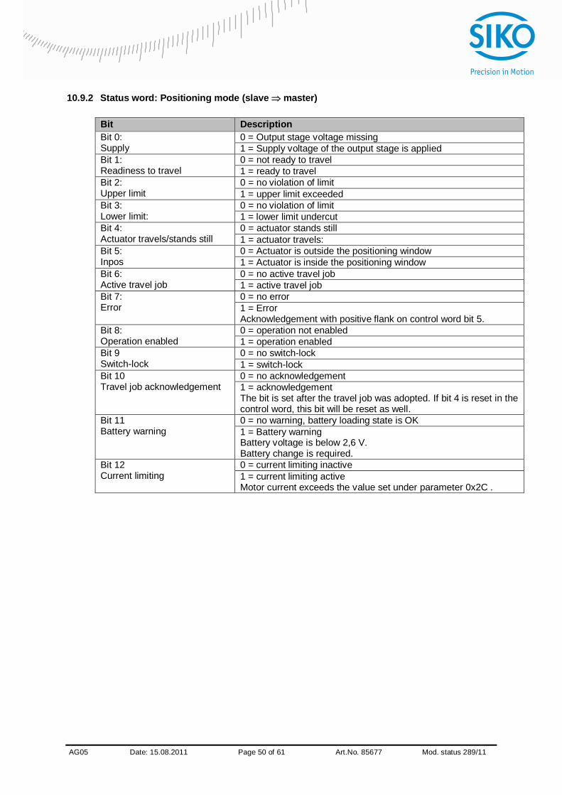
10.9.2 Status word: Positioning mode (slave master)
Bit Description 0 = Output stage voltage missing Bit 0:
Supply 1 = Supply voltage of the output stage is applied 0 = not ready to travel Bit 1:
Readiness to travel 1 = ready to travel 0 = no violation of limit Bit 2:
Upper limit 1 = upper limit exceeded 0 = no violation of limit Bit 3:
Lower limit: 1 = lower limit undercut 0 = actuator stands still Bit 4:
Actuator travels/stands still 1 = actuator travels: 0 = Actuator is outside the positioning window Bit 5:
Inpos 1 = Actuator is inside the positioning window 0 = no active travel job Bit 6:
Active travel job 1 = active travel job 0 = no error Bit 7:
Error 1 = Error Acknowledgement with positive flank on control word bit 5. 0 = operation not enabled Bit 8:
Operation enabled 1 = operation enabled 0 = no switch-lock Bit 9
Switch-lock 1 = switch-lock 0 = no acknowledgement Bit 10
Travel job acknowledgement 1 = acknowledgement The bit is set after the travel job was adopted. If bit 4 is reset in the control word, this bit will be reset as well. 0 = no warning, battery loading state is OK Bit 11
Battery warning 1 = Battery warning Battery voltage is below 2,6 V. Battery change is required. 0 = current limiting inactive Bit 12
Current limiting 1 = current limiting active Motor current exceeds the value set under parameter 0x2C .
AG05
x Date: 15.08.2011 Page 51 of 61 Art.No. 85677 Mod. status 289/11
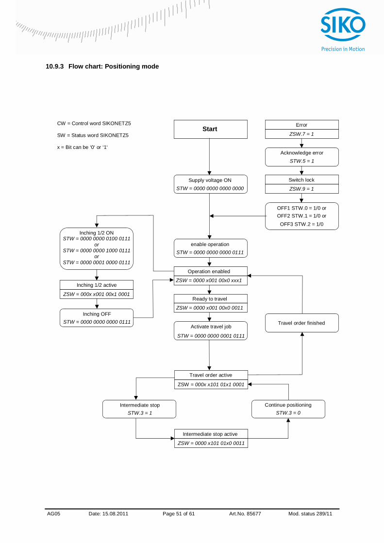
10.9.3 Flow chart: Positioning mode
Activate travel job
STW = 0000 0000 0001 0111
Operation enabled
ZSW = 0000 x001 00x0 xxx1
enable operation STW = 0000 0000 0000 0111
Ready to travel
ZSW = 0000 x001 00x0 0011
Travel order active ZSW = 000x x101 01x1 0001
Intermediate stop STW.3 = 1
Intermediate stop active
ZSW = 0000 x101 01x0 0011
Continue positioning STW.3 = 0
Inching 1/2 ON STW = 0000 0000 0100 0111
or STW = 0000 0000 1000 0111
or STW = 0000 0001 0000 0111
Inching 1/2 active
ZSW = 000x x001 00x1 0001
Inching OFF STW = 0000 0000 0000 0111 Travel order finished
Error
ZSW.7 = 1
Acknowledge error STW.5 = 1
Switch lock
ZSW.9 = 1
OFF1 STW.0 = 1/0 or OFF2 STW.1 = 1/0 or
OFF3 STW.2 = 1/0
Start
Supply voltage ON STW = 0000 0000 0000 0000
CW = Control word SIKONETZ5 SW = Status word SIKONETZ5 x = Bit can be ‘0‘ or ‘1‘
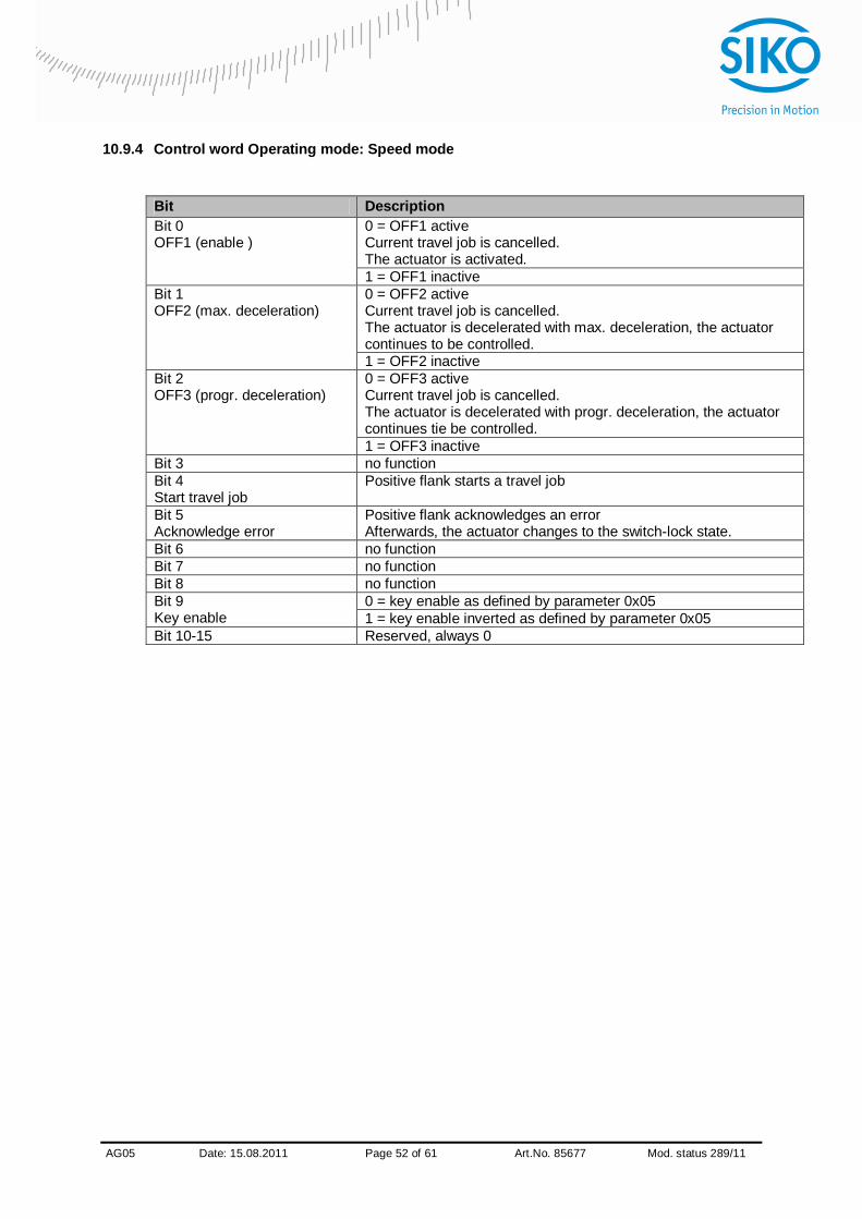
AG05
x Date: 15.08.2011 Page 52 of 61 Art.No. 85677 Mod. status 289/11
10.9.4 Control word Operating mode: Speed mode
Bit Description 0 = OFF1 active Current travel job is cancelled. The actuator is activated.
Bit 0 OFF1 (enable )
1 = OFF1 inactive 0 = OFF2 active Current travel job is cancelled. The actuator is decelerated with max. deceleration, the actuator continues to be controlled.
Bit 1 OFF2 (max. deceleration)
1 = OFF2 inactive 0 = OFF3 active Current travel job is cancelled. The actuator is decelerated with progr. deceleration, the actuator continues tie be controlled.
Bit 2 OFF3 (progr. deceleration)
1 = OFF3 inactive Bit 3 no function Bit 4 Start travel job
Positive flank starts a travel job
Bit 5 Acknowledge error
Positive flank acknowledges an error Afterwards, the actuator changes to the switch-lock state.
Bit 6 no function Bit 7 no function Bit 8 no function
0 = key enable as defined by parameter 0x05 Bit 9 Key enable 1 = key enable inverted as defined by parameter 0x05 Bit 10-15 Reserved, always 0
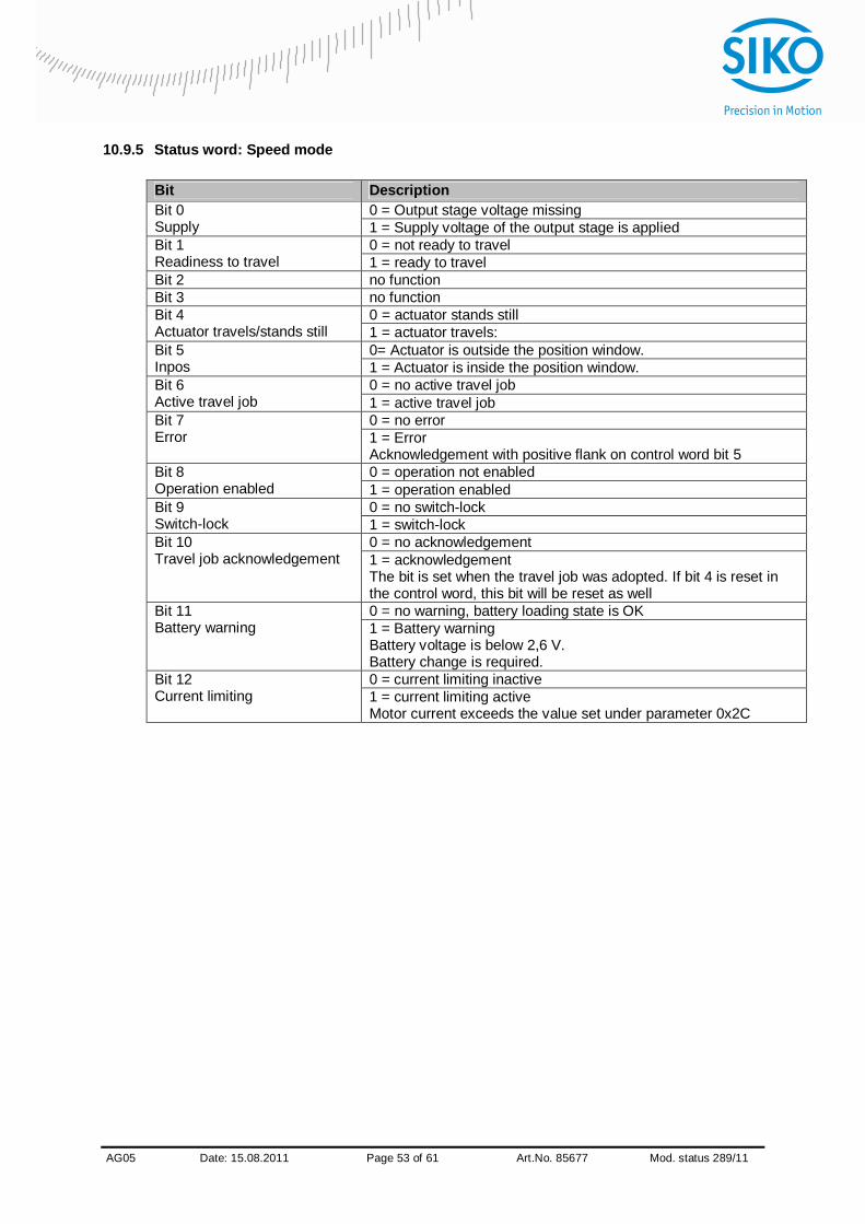
AG05
x Date: 15.08.2011 Page 53 of 61 Art.No. 85677 Mod. status 289/11
10.9.5 Status word: Speed mode
Bit Description 0 = Output stage voltage missing Bit 0
Supply 1 = Supply voltage of the output stage is applied 0 = not ready to travel Bit 1
Readiness to travel 1 = ready to travel Bit 2 no function Bit 3 no function
0 = actuator stands still Bit 4 Actuator travels/stands still 1 = actuator travels:
0= Actuator is outside the position window. Bit 5 Inpos 1 = Actuator is inside the position window.
0 = no active travel job Bit 6 Active travel job 1 = active travel job
0 = no error Bit 7 Error 1 = Error
Acknowledgement with positive flank on control word bit 5 0 = operation not enabled Bit 8
Operation enabled 1 = operation enabled 0 = no switch-lock Bit 9
Switch-lock 1 = switch-lock 0 = no acknowledgement Bit 10
Travel job acknowledgement 1 = acknowledgement The bit is set when the travel job was adopted. If bit 4 is reset in the control word, this bit will be reset as well 0 = no warning, battery loading state is OK Bit 11
Battery warning 1 = Battery warning Battery voltage is below 2,6 V. Battery change is required. 0 = current limiting inactive Bit 12
Current limiting 1 = current limiting active Motor current exceeds the value set under parameter 0x2C

AG05
x Date: 15.08.2011 Page 54 of 61 Art.No. 85677 Mod. status 289/11
10.9.6 Flow chart: Operating mode: Speed mode
Operation enabled
ZSW = 0000 x001 00x0 00x1
Enable operation STW = 0000 0000 0000 0111
Ready to travel
ZSW = 0000 x001 00x0 0011
Sollwert freigeben STW = 0000 0000 0001 0111
Set point enabled
ZSW = 0000 x101 01xx 0001
Change set point STW.4 = 1
Disable set point STW.4 = 0
Error
ZSW.7 = 1
Acknowledge error STW.5 = 1
Switch lock
ZSW.9 = 1
OFF1 STW.0 = 1/0 or OFF2 STW.1 = 1/0 or
OFF3 STW.2 = 1/0
Start
Supply voltage ON STW = 0000 0000 0000 0000
CW = Control word SIKONETZ5 SW = Status word SIKONETZ5 x = Bit can be ‘0‘ or ‘1‘

AG05
x Date: 15.08.2011 Page 55 of 61 Art.No. 85677 Mod. status 289/11
10.10 Parameterization via SIKONETZ5
On principle, the actuator sends a telegram acknowledging write and read commands of the master. With the command executable the value adopted is in the reply telegram. If the actuator was unable to execute the command, e. g. because it attempted to write a value beyond the admissible range, the actuator will send an error telegram in reply. Access rw = read write ro = read only wo = write only
Para- meter
no. [hex]
Name Access Format Description
0x00 Node address rw Unsigned8 Value range 0 – 31 Setting of node address Parameter changes become active only after cold start or software reset. (see chapter 8: Parameter description Parameter no.22)
0x01 Baud rate rw Unsigned8 Setting the baud rate 0 = 19200 1 = 57600 2 = 115200 Parameter changes become active only after cold start or software reset. (see chapter 8: Parameter description Parameter no.33).
0x02 Bus Timeout rw Unsigned16 Value range 0 – 20 (see chapter 8: Parameter description Parameter no.35).
0x03 Reply parameter to Write set point
command
rw Unsigned8 0 = Set point 1 = Actual value 2 = Output stage temperature 3 = Control voltage 4 = Output stage voltage 5 = Battery voltage 6 = Motor current 7 = Actual position 8 = Actual rotational speed (see chapter 8: Parameter description Parameter no.36)
0x04 Enable keys time
rw Unsigned8 Value range 1 – 60 (see chapter 8: Parameter description Parameter no.37)
0x05 Key function enable
rw Unsigned8 0 = key function free 1 = key function locked (see chapter 8: Parameter description Parameter no.38)
0x07 LED 2 orange rw Unsigned8 0 = LED2 Off 1 = LED2 On (see chapter 8: Parameter description Parameter no.39)

AG05
x Date: 15.08.2011 Page 56 of 61 Art.No. 85677 Mod. status 289/11
Para- meter
no. [hex]
Name Access Format Description
0x08 LED 1 red rw Unsigned8 0 = LED1 red Off 1 = LED1 red On (see chapter 8: Parameter description Parameter no.40)
0x09 LED 1 green rw Unsigned8 0 = LED1 green Off 1 = LED1 green On (see chapter 8: Parameter description Parameter no.41)
0x0A Decimal places rw Unsigned8 Value range 0 – 4 (see chapter 8: Parameter description Parameter no.42)
0x0B Display divisor rw Unsigned8 Value range 0 – 3 (see chapter 8: Parameter description Parameter no.43).
0x0C Direction indication function
rw Unsigned8 Value range 0 – 2 (see chapter 8: Parameter description Parameter no.44)
0x0D Display orientation
rw Unsigned8 0 = normal 1 = rotated by 180° (see chapter 8: Parameter description Parameter no.45)
0x0E Programming mode Configuration
rw Unsigned8 0 = no programming mode 1 = apply programming mode (see chapter 8: Parameter description Parameter no.46)
0x0F PIN change rw Unsigned32 Value range 0 – 99999 (see chapter 8: Parameter description Parameter no.48)
0x10 Controller parameter P
rw Unsigned16 Value range 1 – 500 (see chapter 8: Parameter description Parameter no.1)
0x11 Controller parameter I
rw Unsigned16 Value range 0 – 500 (see chapter 8: Parameter description Parameter no.2)
0x12 Controller parameter D
rw Unsigned16 Value range 0 – 500 (see chapter 8: Parameter description Parameter no.3)
0x13 a – Pos rw Unsigned8 Value range 1 – 100 (see chapter 8: Parameter description Parameter no.4)
0x14 v - Pos rw Unsigned8 Value range Gear reduction 98: 1 1 – 30 rpm Gear reduction 173: 1 1 – 16 rpm (see chapter 8: Parameter description Parameter no.5)
0x15 a - rot rw Unsigned8 Value range 1 – 100 (see chapter 8: Parameter description Parameter no.6)
0x16 a - inch rw Unsigned8 Value range 1 – 100 (see chapter 8: Parameter description Parameter no.8)

AG05
x Date: 15.08.2011 Page 57 of 61 Art.No. 85677 Mod. status 289/11
Para- meter
no. [hex]
Name Access Format Description
0x17 v - inch rw Unsigned8 Value range Gear reduction 98: 1 1 – 30 rpm Gear reduction 173: 1 1 – 16 rpm (see chapter 8: Parameter description Parameter no.9)
0x18 ü - Numerator rw Unsigned16 Value range 1 – 10000 (see chapter 8: Parameter description Parameter no.11)
0x19 ü - Denominator rw Unsigned16 Value range 1 – 10000 (see chapter 8: Parameter description Parameter no.12.
0x1A Encoder resolution ro Unsigned16 Constant Value 720 0x1B Sense of rotation rw Unsigned8 0 = i sense of rotation (cw):
1 = e sense of rotation (ccw) (see chapter 8: Parameter description Parameter no.18).
0x1C Spindle pitch rw Unsigned16 Value range 0 – 30000 (see chapter 8: Parameter description Parameter no.13).
0x1E Offset rw Integer32 Value range -999999 – 999999 (see chapter 8: Parameter description Parameter no.32).
0x1F Calibration value rw Integer32 Value range -999999 – 999999 (see chapter 8: Parameter description Parameter no.14).
0x20 Pos- window rw Unsigned16 Value range 0 – 1000 (see chapter 8: Parameter description Parameter no.10).
0x21 Pos type rw Unsigned8 0 = direct 1 = loop + 2 = loop - (see chapter 8: Parameter description Parameter no.19).
0x22 Loop length rw Unsigned16 Value range 0 – 30000 (see chapter 8: Parameter description Parameter no.27).
0x23 Inpos mode rw Unsigned8 0 = position control 1 = short circuit of the motor windings 2 = motor activated (see chapter 8: Parameter description Parameter no.26)
0x24 Delta Inch rw Integer32 Value range -1000000 – 1000000 (see chapter 8: Parameter description Parameter no.17)
0x25 Acceleration type with
Inching mode 2
rw Unsigned8 0 = static acceleration 1 = incremental acceleration (see chapter 8: Parameter description Parameter no.31)
0x26 Inching 2 Offset rw Unsigned8 Value range 10 – 100 (see chapter 8: Parameter description Parameter no.30)

AG05
x Date: 15.08.2011 Page 58 of 61 Art.No. 85677 Mod. status 289/11
Para- meter
no. [hex]
Name Access Format Description
0x27 Stop mode inching 2 rw Unsigned8 0 = maximum deceleration 1 = programmed deceleration (see chapter 8: Parameter description Parameter no.25)
0x28 Operating mode rw Unsigned8 0 = positioning mode 1 = speed mode (see chapter 8: Parameter description Parameter no.20)
0x29 Limit 1 rw Integer32 Value range -9999999 – 9999999 (see chapter 8: Parameter description Parameter no.15).
0x2A Limit 2 rw Integer32 Value range -9999999 – 9999999 (see chapter 8: Parameter description Parameter no.16)
0x2C Current limiting rw Unsigned8 Value range 25 – 110 (see chapter 8: Parameter description Parameter no.29)
0x2D Contouring error limit
rw Unsigned16 Value range 1 – 30000 (see chapter 8: Parameter description Parameter no.28)
0x30 Display value of 2nd line
rw Unsigned8 0 = Set point 1 = Output stage temperature 2 = Control voltage 3 = Output stage voltage 4 = Battery voltage: 5 = Motor current 6 = Actual position 7 = Actual rotational speed (see chapter 8: Parameter description Parameter no.49)
0x60 Output stage temperature
ro Integer16 Temperature values in 1/10 °C (see chapter 8: Parameter description Parameter no.50)
0x61 Voltage of control
ro Integer16 Voltage values in 1/10 V (see chapter 8: Parameter description Parameter no.51)
0x62 Voltage of output stage
ro Integer16 Voltage values in 1/10 V (see chapter 8: Parameter description Parameter no.52)
0x63 Voltage of battery
ro Integer16 Voltage values in 1/100 V (see chapter 8: Parameter description Parameter no.53)
0x64 Motor current ro Integer16 Current values in mA (see chapter 8: Parameter description Parameter no.54)
0x65 Device code ro Unsigned8 0 = AG05 0x66 Display controller
software version ro Unsigned16 Version number
e. g. 103 corresponds to V1.03 (see chapter 8: Parameter description Parameter no.60)

AG05
x Date: 15.08.2011 Page 59 of 61 Art.No. 85677 Mod. status 289/11
Para- meter
no. [hex]
Name Access Format Description
0x67 Motor controller software version
ro Unsigned16 Version number e. g. 108 corresponds to V1.08 (see chapter 8: Parameter description Parameter no.59)
0x68 Serial number ro Unsigned32 Serial number (see chapter 8: Parameter description Parameter no.57)
0x69 Production date ro Unsigned32 Production date in DDMMYYYY format (see chapter 8: Parameter description Parameter no.58)
0x6A Gear reduction ro Unsigned16 98 = gear 98:1 173 = gear 173:1
0x6B Actual position ro Integer32 Spindle pitch = 0 values in increments Spindle pitch > 0 values in 1/100 mm (see chapter 8: Parameter description Parameter no.55)
0x6C Actual rotational speed
ro Integer32 Actual speed in rpm (see chapter 8: Parameter description Parameter no.56)
0x80 Number of errors
ro Unsigned8 Returns the number of errors in the error memory (see chapter 8: Parameter description Parameter no.61.
0x81 Error 1 ro Unsigned8 (see chapter 7.2.1: Error codes (see chapter 8: Parameter description Parameter no.62)
0x82 Error 2 ro Unsigned8 (see chapter 7.2.1: Error codes (see chapter 8: Parameter description Parameter no.63)
0x83 Error 3 ro Unsigned8 (see chapter 7.2.1: Error codes (see chapter 8: Parameter description Parameter no.64)
0x84 Error 4 ro Unsigned8 (see chapter 7.2.1: Error codes (see chapter 8: Parameter description Parameter no.65)
0x85 Error 5 ro Unsigned8 (see chapter 7.2.1: Error codes (see chapter 8: Parameter description Parameter no.66)
0x86 Error 6 ro Unsigned8 (see chapter 7.2.1: Error codes (see chapter 8: Parameter description Parameter no.67)
0x87 Error 7 ro Unsigned8 (see chapter 7.2.1: Error codes (see chapter 8: Parameter description Parameter no.68)
0x88 Error 8 ro Unsigned8 (see chapter 7.2.1: Error codes (see chapter 8: Parameter description Parameter no.69)
0x89 Error 9 ro Unsigned8 (see chapter 7.2.1: Error codes (see chapter 8: Parameter description Parameter no.70)
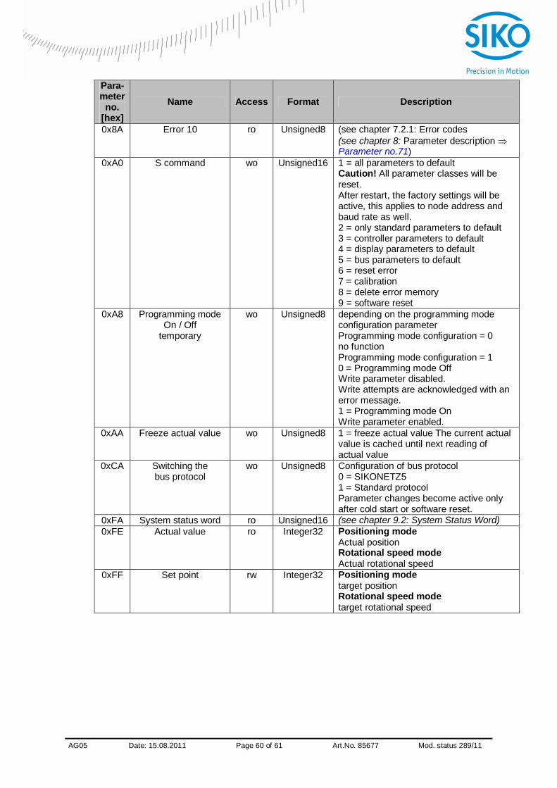
AG05
x Date: 15.08.2011 Page 60 of 61 Art.No. 85677 Mod. status 289/11
Para- meter
no. [hex]
Name Access Format Description
0x8A Error 10 ro Unsigned8 (see chapter 7.2.1: Error codes (see chapter 8: Parameter description Parameter no.71)
0xA0 S command wo Unsigned16 1 = all parameters to default Caution! All parameter classes will be reset. After restart, the factory settings will be active, this applies to node address and baud rate as well. 2 = only standard parameters to default 3 = controller parameters to default 4 = display parameters to default 5 = bus parameters to default 6 = reset error 7 = calibration 8 = delete error memory 9 = software reset
0xA8 Programming mode On / Off
temporary
wo Unsigned8 depending on the programming mode configuration parameter Programming mode configuration = 0 no function Programming mode configuration = 1 0 = Programming mode Off Write parameter disabled. Write attempts are acknowledged with an error message. 1 = Programming mode On Write parameter enabled.
0xAA Freeze actual value wo Unsigned8 1 = freeze actual value The current actual value is cached until next reading of actual value
0xCA Switching the bus protocol
wo Unsigned8 Configuration of bus protocol 0 = SIKONETZ5 1 = Standard protocol Parameter changes become active only after cold start or software reset.
0xFA System status word ro Unsigned16 (see chapter 9.2: System Status Word) 0xFE Actual value ro Integer32 Positioning mode
Actual position Rotational speed mode Actual rotational speed
0xFF Set point rw Integer32 Positioning mode target position Rotational speed mode target rotational speed

AG05
x Date: 15.08.2011 Page 61 of 61 Art.No. 85677 Mod. status 289/11
10.10.1 Example: Read parameter
Reading the parameter Limit 1 of node address 1:
NOTICE With read commands the data range shall be set to value 0.
Read command: 0x00 Node ID 0x01 Parameter address: 0x29 Limit 1 Data: 0x00 00 00 00 Telegram from master to slave:
1st
byte 2nd byte 3rd byte 4th byte 5th byte 6th byte 7th byte 8th byte 9th byte 10th byte Com-mand Node ID Parameter
address STW Data Check sum
0x00 0x01 0x29 0x00 0x00 0x00 0x00 0x00 0x00 0x28
Reply telegram from slave
1st byte 2nd byte 3rd byte 4th byte 5th byte 6th byte 7th byte 8th byte 9th byte 10th byte
Command / reply
Node ID
Parameter address ZSW Data Check
sum 0x00 0x01 0x29 0x00 0x01 0x00 0x01 0x86 0x9F 0x31
The reply telegram contains the current value of parameter limit 1. Data: 0x00 01 86 9F 99 999 dec
10.10.2 Example: Write parameter
Set parameter v-Pos of node address 1 to value 15: Write command: 0x01 Node ID 0x01 Parameter address: 0x14 v-Pos Data: 0x00 00 00 0F Telegram from master to slave:
1st byte 2nd byte 3rd byte 4th
byte 5th
byte 6th byte 7th byte 8th byte 9th byte 10th byte
Command Node ID
Parameter address STW Data Check
sum 0x01 0x01 0x14 0x00 0x00 0x00 0x00 0x00 0x0F 0x1B
Reply telegram from slave
1st byte 2nd byte 3rd byte 4th byte 5th byte 6th byte 7th byte 8th byte 9th byte 10th byte Comma
nd / Reply
Node-ID
Parameter- address ZSW Data Check-
sum
0x01 0x01 0x14 0x00 0x01 0x00 0x00 0x00 0x0F 0x1A


