
ACCELERATED
CORROSION
TESTING OF ASTM
A1010 STAINLESS
STEEL
ISAAC GROSHEK
DR. MATTHEW HEBDON
BIOGRAPHY
Isaac Groshek is a Structural
Engineer with the Middleton,
WI Office of AECOM. His
current work involves the
design of steel and prestressed
concrete girder highway
bridges, retaining walls, and
sign structures. Prior to working
at AECOM, Isaac received a
bachelor’s in civil engineering
from the University of
Wisconsin-Madison and a
master’s degree in civil
engineering from Virginia Tech.
His graduate research focused
on the corrosion behavior of
stainless steels with applications
in the bridge industry.
Matthew is an assistant
professor in the Charles E. Via,
Jr. Department of Civil &
Environmental Engineering at
Virginia Tech. He received his
doctorate in Civil Engineering
in 2015 from Purdue University.
Prior to this he worked as a
design engineer at Sargent
Engineers, Inc. from 2005 until
2010. He earned both a master's
and a bachelor's degree in civil
and environmental engineering
from Utah State University. His
research experience includes
redundant behavior of steel
bridges, fatigue and fracture
evaluation of steel structures,
bridge monitoring and testing,
historical fabrication methods
and materials, and large scale
testing of structures. He is a
member of the TRB AFH70 -
Fabrication and Inspection of
Metal Structures committee, and
the AREMA Committee 15 –
Steel Structures.
SUMMARY
ASTM A1010 (recently adopted
as ASTM A709 Gr50CR) is a
material which has
advantageous corrosion
properties. It is a low-grade
stainless steel which forms a
protective patina and has been
marketed as an alternative to
other bridge steels and corrosion
protection methods due to its
corrosion resistance in highly
corrosive environments.
However, the material is
currently available in plate form
only, and several of the
applications in the United States
were required to use alternative
materials when constructing and
connecting secondary members
to the A1010 plate girders.
This paper addresses the
corrosion behavior of A1010 in
several different details relating
to recent applications in the US.
An accelerated corrosion study
was performed which simulated
a highly corrosive environment
typical of the environment
justifying the use of A1010.
The research investigated the
resulting galvanic corrosion and
its effect on the corrosion rate of
A1010 plates, several different
common bridge steels, and
typical fastener materials. In
addition, common surface
preparation methods were
evaluated for their aesthetic
effect during patina formation.

Page 1 of 12
ACCELERATED CORROSION TESTING OF ASTM A1010
STAINLESS STEEL
Introduction
The steel bridge industry has been combating the
issue of corrosion ever since the first use of
structural steel in bridges in the 19th century. Early
efforts to reduce the magnitude of corrosion focused
on the application of protective coatings, such as
paint systems, to the steel surface. The durability of
these systems varied widely based on the corrosivity
of the environment and the breakdown of the
systems in corrosive environments.
Later efforts focused on improving the corrosion
resistance of uncoated structural steel; in the 1970s,
weathering steel was introduced with hopes of
providing a material that could resist corrosion
without requiring a coating and subsequent
maintenance. While weathering steel performed
well in many applications, high corrosion rates in
highly-corrosive environments, such as locations
with high exposure to deicing chemicals and marine
environments, has resulted in recommendations to
avoid these types of environments (1)(2). Similar
recommendations apply to hot-dip galvanizing and
thermal-spray metalizing. While these systems have
proven to provide corrosion protection in low to
mildly-corrosive environments, coating breakdown
may occur in less than 40 years in highly corrosive
environments, and these coatings provide challenges
for in-situ repairs (1). As such, a cost-efficient
structural material which requires little to no
maintenance over its service life in corrosive
environments has wide potential in the steel bridge
industry.
In recent decades, a new stainless steel option, under
the ASTM A1010 specification, has been introduced
for use in primary bridge members. Originally
developed as a lower-cost alternative to higher
chromium-content stainless steels, A1010 stainless
steel has been estimated to exhibit corrosion
resistance approximately 4 to 10 times that of
weathering steels (3).
A1010, similar to all other stainless steels, provides
corrosion resistance through the natural formation of
a protective chromium oxide surface layer in the
presence of oxygen. Testing of A1010 has proven
its ability to satisfy the mechanical requirements of
ASTM A709 GR50 steel, and as such, A1010 has
been used for primary members on six bridges
within the United States (3). Recently, A1010 has
been added to the ASTM A709 specification as
ASTM A709 GR50CR. In specific bridge
applications, three characteristics of the corrosion
behavior remained relatively unknown:
1. Galvanic corrosion. When dissimilar metals
share an electrical connection and are
connected through an electrolyte medium,
accelerated corrosion of the more reactive
metal will occur. Also known as bimetallic
corrosion (4).
2. Crevice corrosion. When crevice-like
conditions occur on the surface of a stainless
steel such that a corrosive substance may
infiltrate and reside, the resulting acidity of the
trapped solution and lack of oxygen often
results in accelerated rates of corrosion (5).
3. Effect of surface preparation. After
fabrication, steel bridge members commonly
receive blasting or grinding on their surface for
aesthetic purposes and/or to prepare for
painting. This process ultimately changes the
surface profile of the steel and may affect the
corrosion behavior of the steel.
Given that no structural bolts or shear connectors
closely match the chemical composition specified in
ASTM A1010, any realistic use of A1010 with
bolted connections in primary bridge members will
result in a bimetallic connection. Additionally,
hybrid girders, which use A1010 plate members
only in the most vulnerable locations while
combining them with traditional structural steel
components, have been considered. The magnitude
of galvanic corrosion and the effect on both metals
in the connection is of interest. The rate of galvanic
corrosion in such detailing may also be dependent
upon the surface area ratio of the anode (more
reactive metal) to cathode (less reactive metal, likely
A1010) within the electrolyte facilitating the
reaction (4).
While the corrosion resistance of A1010 has been

Page 2 of 12
found to significantly exceed that of weathering steel
for isolated corrosion specimens, it is hypothesized
that this resistance may be notably decreased with
A1010 use in connections containing crevice-like
details. The lack of oxygen in these
microenvironments stifles the ability of stainless
steels to adequately form a chromium oxide passive
surface layer. Common details in steel bridge
girders, such as bolted field splice connections,
create opportunities for such conditions to occur, and
are of interest for applications with A1010.
Abrasive blasting of steel bridge members has been
widely automated with the use of wheel abrasive
blasting machines which can accommodate full-size
plate girders in a single pass. The most common
blasting media is rounded steel shot which is more
easily recollected and creates less damage on the
blasting chamber compared to jagged grit blasting
media such as Aluminum Oxide or Garnett. For the
majority of structural stainless steels, the use of
carbon steels in cleaning procedures is avoided to
prohibit excess loose iron from being transferred to
the stainless steel and consequent corrosion products
to form on the surface. The type of abrasive media
used in blasting may have a notable effect on the
surface profile of A1010 and the resulting corrosion
behavior.
Experimental Setup
Corrosion research has been traditionally conducted
by three methods: 1) investigation of historical data
on bridge corrosion performance, 2) in-situ
corrosion testing of specimens, and 3) accelerated
corrosion testing of specimens. Due to time
constraints and lack of historical corrosion data for
ASTM A1010 stainless steel, the research team
selected the third option, accelerated corrosion
testing. The objective was to implement an
accelerated procedure which would produce
corrosion behavior representative of previously
performed in-situ testing and one which is already
generally accepted within the bridge industry.
While several different procedures exist, the
modified SAE J2334 Surface Vehicle Standard was
chosen (6). This procedure had been implemented
in two independent FHWA corrosion studies and
was found to be useful for comparing corrosion
behavior of specimens in identical cyclical testing
environments (3)(7).
The modified SAE J2334 procedure consists of a
repeated 3-stage cycle: 1) humid stage at 50°C and
100% relative humidity (RH) for 6.00 hours, 2) salt
application stage with full immersion in salt solution
at ambient temperatures for 0.25 hours, and 3) dry
stage at 60°C and 50% relative humidity (RH) for
17.75 hours (3)(6)(8). The humid and dry stage
environments were created through the use of an
automated environmental chamber, while the salt
application stage was implemented by manually
placing the specimens in soaking tubs filled with the
solution. The salt solution was modified from the
original SAE J2334 specification to have 5.0
percentage weight of sodium chloride instead of 0.5
percentage weight, based on previous FHWA
findings (3). Plastic racks and shelving were used to
orient specimens during testing and facilitate
movement between environmental chamber and
soaking tub, as shown in Figure 1.
Figure 1: Test specimen configuration in
environmental chamber and salt solution
The specimen orientation was selected to produce
conditions suitable for each type of corrosion of
interest. Corrosion is known to accelerate with
increasing time of wetness (TOW), or exposure of
the metal to the electrolyte. This was controlled by
orienting the specimens at position which allowed
electrolytes to remain on the specimen surface for a
longer time prior to drying.
Five specimen and specimen assembly types were
included in the corrosion testing. In general, the
term “specimen” refers to an individual plate or
fastener component (bolt, nut, or washer) while
“specimen assembly” refers to a combination of
plates or fasteners connected together during testing.
The testing setup types were as follows:
1. Control Plate Specimens. Control plate
specimens were included to provide baseline data
and means of comparison with past corrosion

Page 3 of 12
studies. The four steel types included were
ASTM A1010 GR50 (A709 GR50CR), A709
GR50, A709 GR50W, and A709 GR50 with hot-
dip zinc galvanized (HDG) coating per ASTM
A123. Triplicates were provided for each steel
type to reduce sampling error and placed in a
near-vertical orientation, at 15° from vertical,
typical of the SAE J2334 Standard (6). All plates
were 4 in. squares with a thickness of 3/8 in.
These plates are shown in Figure 2.
Figure 2: Control plate specimens in plastic racks
prior to the initiation of testing
2. Galvanic Corrosion Plate Assemblies. A1010
(A709 GR50CR) base plates were directly
connected to conventional structural steel top
plates to investigate the galvanic corrosion
behavior resulting from the bimetallic
connection. Top plate steel types included the
same three A709 types from the control plates:
GR50, G50W, and GR50 HDG. Three different
top plate sizes were used in “direct connect”
specimen assemblies in an attempt to investigate
the surface area of the anode to cathode involved
in the galvanic corrosion reaction. Base plate
sizes were 4 in. by 6 in., and top plate sizes were
1.75 in. squares, 2.50 in. squares, and 4 in. by 3
in. rectangles. All plates had thicknesses of 3/8
in.
For each type of steel, additional specimens were
included which inhibited galvanic corrosion via a
nylon plate barrier between the metals. This
provided a comparison between “direct connect”
and “nylon barrier” specimens to estimate the
magnitude of galvanic corrosion on the direct
connect specimens. Specimen assemblies were
placed in a near-horizontal orientation, at 85°
from vertical, to provide an environment
representative of a steel girder bottom flange and
provide a higher TOW. Duplicates were
provided for each assembly type to reduce
sampling error. Galvanic corrosion plate
assemblies are shown in Figure 3.
Figure 3: Galvanic corrosion plate assemblies in
plastic racks prior to the initiation of testing
3. Galvanic Corrosion Fastener Assemblies. In a
similar concept to the plate assemblies, the
fastener assemblies included A1010 plates
connected to conventional fastener assemblies.
The fastener types were also connected to
separate nylon plates to provide a comparison of
assemblies allowing galvanic corrosion and those
that do not allow galvanic corrosion. Six
fasteners types were included from three
categories: uncoated carbon and weathering steel,
HDG carbon steel, and stainless steel. For a
complete list, see Table 1. A1010 plates were 4
in. squares with a thickness of 3/8 in. and bolts
were 3/4 in. in diameter and 2 in. long.
Triplicates were provided for each assembly type
to reduce sampling error. The plates were placed
in a near-vertical orientation, at 15° from vertical,
as shown in Figure 4.
Table 1: Fastener combinations for galvanic
corrosion fastener assemblies
Bolt Type Nut Type Washer
Type
A325 Type 1 A563 C F436 Type 1
A325 Type 3 A563 C3 F436 Type 3
A325 Type 1
HDG A563 DH HDG
F436 Type 1
HDG
A490 Type 1 A563 DH F436 Type 1
A193 B8 Class2 A194 Gr8 Class2 410SS
A193 B6 A194 Gr6 410SS
Page 4 of 12
Figure 4: Galvanic corrosion fastener assemblies in
plastic racks prior to the initiation of testing
4. Crevice Corrosion Plate Assemblies. A1010
base plates were directly connected to A1010 top
plates in order to investigate the crevice corrosion
behavior of A1010 stainless steel when not
involved in bimetallic connections. Base plates
were 4 in. squares and top plates were 3 in.
squares, with both types of plates having a
thickness of 3/8 in. It was hypothesized that the
surface preparation which the specimens received
may have a significant impact on crevice
corrosion. Therefore, specimen assemblies were
included in which both the top and bottom plates
received aluminum oxide abrasive blasting, in
addition to assemblies in which neither the top
nor bottom plate received any abrasive blasting.
The two types of assemblies are shown in Figure
5. Specimen assemblies were placed in a near-
horizontal orientation, at 85° from vertical.
Figure 5: Crevice corrosion fastener assemblies in
plastic racks prior to the initiation of testing
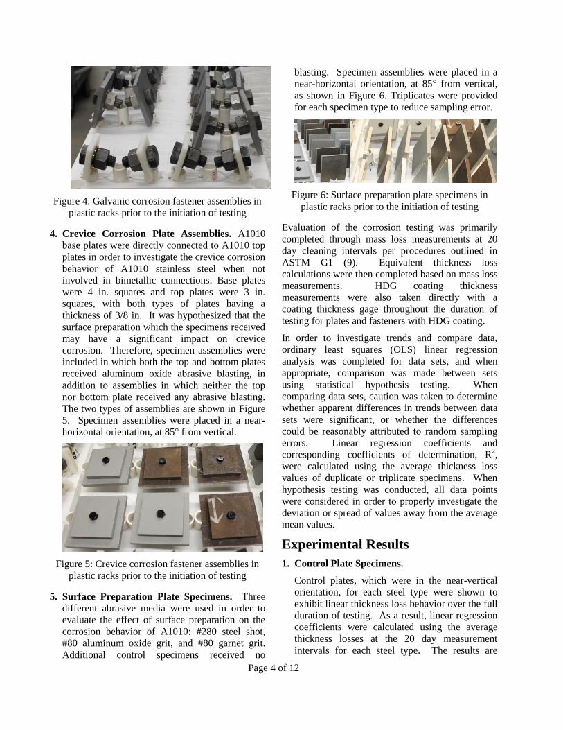
5. Surface Preparation Plate Specimens. Three
different abrasive media were used in order to
evaluate the effect of surface preparation on the
corrosion behavior of A1010: #280 steel shot,
#80 aluminum oxide grit, and #80 garnet grit.
Additional control specimens received no
blasting. Specimen assemblies were placed in a
near-horizontal orientation, at 85° from vertical,
as shown in Figure 6. Triplicates were provided
for each specimen type to reduce sampling error.
Figure 6: Surface preparation plate specimens in
plastic racks prior to the initiation of testing
Evaluation of the corrosion testing was primarily
completed through mass loss measurements at 20
day cleaning intervals per procedures outlined in
ASTM G1 (9). Equivalent thickness loss
calculations were then completed based on mass loss
measurements. HDG coating thickness
measurements were also taken directly with a
coating thickness gage throughout the duration of
testing for plates and fasteners with HDG coating.
In order to investigate trends and compare data,
ordinary least squares (OLS) linear regression
analysis was completed for data sets, and when
appropriate, comparison was made between sets
using statistical hypothesis testing. When
comparing data sets, caution was taken to determine
whether apparent differences in trends between data
sets were significant, or whether the differences
could be reasonably attributed to random sampling
errors. Linear regression coefficients and
corresponding coefficients of determination, R2,
were calculated using the average thickness loss
values of duplicate or triplicate specimens. When
hypothesis testing was conducted, all data points
were considered in order to properly investigate the
deviation or spread of values away from the average
mean values.
Experimental Results
1. Control Plate Specimens.
Control plates, which were in the near-vertical
orientation, for each steel type were shown to
exhibit linear thickness loss behavior over the full
duration of testing. As a result, linear regression
coefficients were calculated using the average
thickness losses at the 20 day measurement
intervals for each steel type. The results are

Page 5 of 12
shown in Table 2.
Table 2: Average thickness loss rates (linear
regression coefficients) of control plate specimens.
Steel Type Coefficient
(mils/cycle)
R2
A1010 GR50 0.021 0.990
A709 GR50 0.237 0.999
A709 GR50W 0.214 0.999
A709 GR50 HDG 0.022 0.983
For control plate specimens, the thickness loss
rate of the A1010 plates was approximately 12
times less than that of the A709 GR50, 10 times
less than the A709 GR50W, and similar to the
A709 GR50 HDG plates.
Corrosion behavior of control specimens
corresponded to whether each steel type was able
to form a passive surface layer in the highly-
corrosive testing environment. Thickness loss
data and visual observations confirmed that all
three A709 control specimen types were unable
to properly form passive surface layers and
experienced unstable corrosion. Conversely, the
A1010 (A709 GR50CR) plates experienced
stable corrosion, with a passive surface layer
being able to properly form. This is depicted in
Figure 7.
Figure 7: Control plate specimens through 20 testing
cycles
A comparison of the current Virginia Tech (VT)
study thickness loss rates with loss rates from a
recent FHWA study was made, as listed in Table
3. Within both studies, the A1010 stainless steel
was shown to experience approximately 10 times
less corrosion loss compared to the weathering
steel specimens. However, the relative corrosion
rates varied between the studies; specimens
within the VT study experienced thickness loss
rates approximately 20% less than the FHWA
study. This difference may be attributed, at least
in part, to the different methods for the salt
application stage, corrosion chambers used, and
abrasive blasting media used for cleaning.
Table 3: Comparison of thickness loss rates of
control plates from VT and FHWA corrosion
studies.
Steel Type
Coefficient (mils/cycle)
[thickness loss - two sides]
FHWA VT
A1010 GR50 0.050 0.042
A588/A709GR50W 0.519 0.428
2. Galvanic Corrosion Plate Assemblies.
A1010 (A709 GR50CR) base plates. Base
plates connected to the uncoated A709 GR50 &
GR50W top plates experienced thickness loss
rates which were between 3 to 8 times greater
than the A1010 control plates and increased
with time.
In general, the increase in magnitude was
attributed to the near-horizontal orientation of
the specimens which caused a higher TOW and
longer exposure to corrosive substances.
Unstable corrosion was observed, as the plates
were unable to properly form a passive surface
layer, as seen in Figure 8. This behavior was
nearly equivalent for assemblies with each of
the three sizes of top plate.

Page 6 of 12
Figure 8: Unstable corrosion occurring on A1010
base plate connected to uncoated A709 top plate
The increase in thickness loss rates over time
was attributed to crevice and pitting corrosion
occurring in between the faying surfaces of the
connected plates; as the depth of the crevices
increased, the crevice corrosion rate also
increased.
A1010 (A709 GR50CR) base plates connected
to coated A709 GR50 HDG plates experienced
thickness loss rates between 1.5 to 3 times
greater than the A1010 control plates. The base
plates experienced near-linear thickness loss
rates up to 60 cycles of testing, at which point
the HDG sacrificial surface layer on the top
plates was fully depleted.
The decrease in thickness loss, compared to the
uncoated carbon and weathering steel
assemblies, was attributed to the sacrificial
protection provided by the top plate zinc
coating. The coating provided immediate
protection on the faying surface between the
plates within approximately 1 inch from the top
plate connection, as seen in Figure 9. This
protection was evident when comparing base
plates connected to the varying top plate sizes;
A1010 base plates connected to the largest
A709 GR50 HDG top plates received the
greatest protection and experienced the lowest
thickness lost rates, while the assemblies with
the smallest top plates received the least
protection and experienced the greatest
thickness loss rates.
Figure 9: Galvanic protection occurring on A1010
base plate connected to HDG coated A709 top plate
The sacrificial protection resulted in the
prevention of crevice corrosion on the faying
surface of the A1010 base plate in direct
connect specimens, but did not for the nylon
barrier assemblies. As a result, A1010 base
plates in nylon barrier assemblies experienced
approximately 50% increase in thickness loss
rates. However, protection on direct connect
assemblies did not cover the full surface of the
base plate, but was localized adjacent to the top
HDG plate. A comparison of A1010 plates
after the full 80 cycles of testing after having
been cleaned is shown in Figure 10.
Figure 10: A1010 base plates from direct connect
A709 assemblies, GR50 (left) & GR50 HDG (right)
Uncoated A709 GR50 & GR50W top plates.
Uncoated top plates connected to the A1010
(A709 GR50CR) base plates experienced
linear thickness loss rates which were
approximately 1.5 times greater than the
uncoated A709 control plates. The overall
increase in thickness loss rates was attributed
to the change in the assembly testing
orientation to a near-horizontal setup. This
increased the TOW of the plates and provided
longer exposure of the plates to corrosive

Page 7 of 12
substances. Unstable corrosion was observed,
as the plates were unable to properly form a
passive surface layer, as seen in Figure 11.
Figure 11: A709 GR50W top plates after 20 cycles
of corrosion testing
A709 GR50 & GR50W top plates in nylon
barrier assemblies experienced an approximate
10% decrease in thickness loss rates compared
to direct connect assemblies. This indicated
that the effect of galvanic corrosion for these
top plates was minor, which may be attributed
to the minor difference in the electric
potentials of the A1010 and A709 GR50 and
GR50W metals.
The variation in size for these top plates
appeared to have little effect on their thickness
loss rates. Based on these results, it is
believed that the main electrolyte participating
in galvanic corrosion was located between the
faying surfaces of the top and base plates, as
seen in Figure 12. This configuration
indicates a 1:1 surface area of anode (top
plate) to cathode (base plate) for each top plate
size. Therefore, a change in top plate would
not change the surface area ratio of anode to
cathode participating in galvanic corrosion
within the assembly.
Figure 12: Diagram showing electrolyte permitting
galvanic corrosion located primarily between faying
surfaces of connected plates
Coated A709 GR50 HDG top plates. Coated
top plates connected to the A1010 (A709
GR50CR) base plates experienced thickness
loss rates approximately 3 times greater than
the coated A709 HDG control plates for nylon
barrier assemblies and 5 times greater for
direct connect assemblies. Thickness loss
rates experienced considerable bilinear
behavior, with a noticeable change in slope at
60 cycles, corresponding to the full depletion
of the sacrificial HDG coating, as shown in
Figure 13. The overall increase in thickness
loss rates for both assembly types is attributed
to the change in the assembly testing
orientation to a near-horizontal setup. Similar
to the control A709 GR50 HDG plates, these
top plates exhibited unstable corrosion, as the
plates were unable to properly form a passive
surface layer.
Figure 13: Comparison of direct connect and nylon
barrier A709 GR50 HDG top plates
A709 GR50 HDG top plates in nylon barrier
assemblies experienced an approximate 40%
decrease in thickness loss rates compared to
direct connect assemblies. This indicates that
the effect of galvanic corrosion for these top
plates was significant. Additionally, direct
coating measurement thicknesses revealed that
HDG top plates in nylon barrier assemblies
experienced approximately 25% greater
thickness loss rates on the faying surface of
the plate compared to the exposed face. For
HDG top plates in direct connect assemblies,
the loss rates were 50% greater for the faying
surface. This reaffirms that while crevice
corrosion did cause some disparity between
thickness loss rates on front and back faces for
both assembly types, a significant amount of
galvanic corrosion occurred between the
faying surfaces of the A1010 and A709 GR50
HDG top plates for direct connect assemblies.
For these top plates, no clear effect on
thickness loss rates was observed for top
plates with varying size. This is attributed to
the same behavior as the uncoated A709 top
plates; the primary contributing electrolyte
was located between the faying surfaces of the
connected plates.

Page 8 of 12
3. Galvanic Corrosion of Fastener Assemblies.
A1010 plates. Overall, thickness loss rates
experienced by the A1010 plates within the
galvanic corrosion fastener assemblies were
approximately equivalent to the losses
exhibited by the A1010 control plate
specimens, at 0.02 mils/cycle. A1010 plates
connected to all fastener types exhibited
nearly linear thickness loss rates over the
duration of testing. The A1010 plates in
uncoated carbon and weathering steel bolt
assemblies experienced thickness loss rates of
approximately 0.02 mils/cycle, those
connected to HDG bolt assemblies
experienced approximately 0.01 mils/cycle,
and those connected to B8 Class 2 and B6
stainless steel bolt assemblies experienced
approximately 0.03 mils/cycle.
Figure 14: Galvanic corrosion fastener assemblies
after 20 cycles of testing.
In general, these differences in thickness loss
rates among A1010 plates connected to
dissimilar metal bolt assemblies were
relatively small in magnitude, even while the
percentage increase or decrease appears to be
significant. This was due to the passive
surface layer formation on the A1010 surface
for each of these specimen assemblies and the
relatively small portion of surface area on the
A1010 plates participating in galvanic
corrosion. This behavior would likely
increase in an environment in which the
electrolyte connecting the plates was thicker
or connected the two components for a longer
period of time. Given that the use of A1010 in
bridge applications would involve atmospheric
environments without constant immersion in
an electrolyte solution, the effect of galvanic
corrosion for the A1010 plates when
connected to these fastener types appears to be
minimal.
General Fastener Data. Thickness loss values
were calculated for fastener specimens under
the assumption that all thickness loss occurred
on the exposed surfaces, rather than the total
surface area. While this assumption proved to
be a relatively accurate approximation, as
shown in Figure 15, some corrosion loss
occurred on surfaces not exposed to the bulk
environment due to the salt solution
penetrating into the crevices existing in the
specimen assemblies. Therefore, fastener
thickness loss rates were best used for
comparisons for each type of assembly
connected to nylon and A1010 plates and also
for comparisons between different bolt
assembly types rather than comparison to rates
from plate specimens.
Figure 15: Depiction of relative thickness loss of
bolt material based on level of exposure of surface
Uncoated carbon and weathering steel
fasteners. The uncoated carbon and
weathering steel bolt assemblies, A325 Type
1, A325 Type 3, and A490 Type 1, all
exhibited significantly large amounts of
thickness loss over the test duration,
approximately 0.2 mils/cycle. The thickness
loss rates of these three bolt assembly types
were over twice the rates experienced by the
assembly type with the next closest rates, the
B6 ferritic stainless steel bolts. Additionally,
similarly to the carbon and weathering steel
plate specimens, the A325 Type 1 and Type 3
specimen assemblies experienced negligible
increases in thickness loss from galvanic
corrosion when connected to A1010 plates as
compared to connections with nylon plates.

Page 9 of 12
For these uncoated fastener types, the unstable
uniform corrosion resulting from the corrosive
environment caused thickness loss rates, as
depicted in Figure 16, which were far greater
than any increase from galvanic corrosion.
Figure 16: A325 Type 3 bolt specimens from A1010
plate assembly
In contrast to the A325 Type 1 and Type 3
assemblies, the A490 Type 1 bolt assemblies
experienced statistically significant effects of
galvanic corrosion for the nuts and bolts
connected to A1010 specimens. This behavior
is intriguing given that the chemical
composition requirements for A325 Type 1
and A490 Type 1 specimens are nearly
identical. This behavior may be attributed, in
some respect, to the varying heat treatments
applied to each bolt type. However, for the
end purpose of this study, it is sufficient to
note that the use of A490 Type 1 bolt
assemblies with A1010 plates would likely
result in prohibitive thickness loss rates of the
A490 bolt assemblies due to a combination of
uniform and galvanic corrosion.
HDG coated carbon steel fasteners. The
HDG coating on the fasteners provided an
effective means of protecting the steel below
throughout the duration of testing, with
thickness loss rates of approximately 0.04
mils/cycle. However, the effect of galvanic
corrosion occurring on the HDG specimens
connected to A1010 plates was proven to be
statistically significant and ultimately resulted
in an increase in rates of thickness loss of
approximately 30% as compared to nylon
plate assemblies in which no galvanic
corrosion was present. A comparison of the
bolts connected to the different plate types is
shown in Figure 17.
Figure 17: Comparison of A325 Type 1 HDG bolt
specimens from nylon and A1010 plate assemblies
In corrosive environments, it is possible that
the depletion of the HDG coating on these
bolts would occur at rates up to 30% higher
when connected to A1010 plates due to the
effects of galvanic corrosion. This increase in
coating thickness loss rates is also
accompanied by staining on the A1010
specimens caused by the shedding of the HDG
coating from the bolt assemblies, which may
be visually unappealing.
B6 (Ferritic) stainless steel fasteners. B6
bolts exhibited a moderate amount of
thickness loss due to corrosion, approximately
1 mil/cycle, and also experienced a
statistically significant increase in thickness
loss from galvanic corrosion. The B6 bolts
experienced approximately a 50% increase in
corrosion from galvanic corrosion, and the
GR6 nuts experienced roughly a 300%
increase.
For both of these specimens, the thickness loss
average rate when connected to A1010 plates
was approximately 0.2 mils/cycle per exposed
surface. This thickness loss rate was roughly
half of the rate experienced by the uncoated
carbon and weathering steel bolt assemblies
when connected to A1010 plates. This
thickness loss rate was accompanied by a
significant amount of pitting corrosion around
the shank of the bolt and around the exposed
threads, as shown in Figure 18. The extensive
pitting corrosion seen on the B6 bolts
connected to an A1010 plate requires further
investigation of this behavior if these bolt
assemblies are to be specified for use with

Page 10 of 12
A1010 plates in highly-corrosive
environments.
Figure 18: A193 B6 bolt specimens from A1010
plate assembly, showing pitting corrosion
B8 Class 2 (Austenitic) stainless steel
fasteners. Thickness loss on these austenitic
bolts was negligible over the testing duration
when attached to both nylon and A1010
plates. In the end, it was determined that
galvanic corrosion from these bolt assemblies
caused a slight increase in the thickness loss
rate of the A1010 plates to which they were
connected. However, the magnitudes of these
losses were relatively minimal, roughly 0.01
mils/cycle, and did not appear to be
prohibitive for the use of this bimetallic
connection.
4. Crevice Corrosion Plate Assemblies. A1010
base plates and top plates experienced thickness
loss rates which were roughly linear over the full
duration of testing and approximately 4 times
greater than the A1010 control plates. The
thickness loss rates were nearly equivalent for
specimens having received abrasive blasting and
those without blasting, with any apparent
differences not being statistically significant.
The increase in thickness loss for these plates
compared to control plates was attributed to the
near-horizontal orientation of the specimens
which resulted in unstable corrosion was
observed, and the plates were unable to properly
form a passive surface layer. The increase in
thickness loss rates over time was attributed to
crevice and pitting corrosion occurring in
between the faying surfaces of the connected
plates. The relatively significant amount of
pitting corrosion shown on A1010 base plate
specimens is shown in a comparison with control
plates in Figure 19.
Figure 19: Comparison of A1010 control and crevice
corrosion specimens
5. Surface Preparation Plate Specimens. For
surface preparation specimens, mass loss data
was collected only following 80 cycles of testing
in order to allow the specimens to experience
continuous corrosion over the full duration of
testing. Therefore, more focus was given toward
the visual appearance of the plates.
Mass loss data from these plate specimens
showed that specimens having received
aluminum oxide grit and no abrasive blasting
experienced slightly greater thickness loss rates,
approximately 0.02 mils/cycle. Conversely,
specimens having received garnet grit and steel
shot abrasive blasting experienced slightly less
thickness loss rates, approximately 0.01
mils/cycle. For all specimens, the thickness loss
rates were very low, indicating stable corrosion
associated with the A1010 plates being able to
form a passive surface layer. Thickness loss rates
are listed in Table 4.
Table 4: Average thickness loss rates (linear
regression coefficients) for surface preparation
specimens
Surface Preparation Type Coefficient
(mils/cycle)
Aluminum Oxide Grit 0.025
No Abrasive Blasting 0.017
Garnet Grit 0.008
Steel Shot 0.006
Visual observations of the A1010 specimens
indicated that the main difference in corrosion
behavior of the various specimens was the
appearance of corrosion products on plates
blasted with grit media at earlier stages of testing.
Conversely, specimens blasted with steel shot

Page 11 of 12
specimens did not experience the same
appearance of corrosion products at early stages
of testing. By later stages of testing, all
specimens had uniform distribution of corrosion
products and appeared approximately visually
equivalent.
The difference in early corrosion behavior is
likely the result of the difference in surface
profiles produced by the different blasting media;
the use of shot media produces a microscopic
surface profile which is rounded and wavy, with
“hills” and “valleys” randomly spaced on the
surface. In addition, the collisions of shot media
with the A1010 steel produce minor work
hardening of the surface. This profile type is not
prone to trap moisture and facilitate localized
corrosion. Therefore, the corrosion products do
not appear as readily and may appear less
uniform. In contrast, the use of grit media
produces a microscopic surface profile with
jagged peaks which facilitates moisture and traps
corrosive substances. This microenvironment
produces corrosion products on the A1010
surface at earlier stages of exposure which are
likely to be more evenly distributed on the
surface. A visual comparison of the specimens is
shown in Figure 20.
Figure 20: Comparison of A1010 surface preparation
plate specimens at early and late stages of testing
In atmospheric conditions, the difference in early
corrosion behavior may be more apparent, as the
TOW of the steel will be less than accelerated
corrosion testing conditions. Such behavior may
be increased further in environments where
corrosion products are not evenly applied to the
steel surface, such as in bridges exposed to the
splashing of deicing salts from a roadway below.
Conclusions
All specimens were subjected to accelerated
corrosion tests in a simulated highly corrosive
environment. Therefore the following conclusions
apply to applications where members and/or
components would be exposed to severe corrosive
substances, such as marine environments, locations
with large amounts of applied deicing salts, and near
heavy industrial locations.
On the use of ASTM A1010 plates:
The orientation of the A1010 plate may have a
significant impact on its ability to form a
passive surface layer. In horizontal
orientations, the plate will experience higher
time of wetness and greater exposure to
corrosive substances, thereby presenting more
difficulty for the natural formation of the
protective surface layer.
A1010 is expected to have 4 times greater
resistance in near-horizontal orientations and
10 times greater resistance in near-vertical
orientations relative to A709 Gr50W.
In details which are prone to trapping moisture
and condensation, A1010 experienced notable
pitting corrosion.
The use of steel shot blasting media on A1010
may result in a slight reduction in thickness loss
rates compared to grit media, and may result in
a more uneven aesthetic formation of corrosion
products at early exposure of the metal to the
environment compared to the grit media.
However, long-term aesthetics do not appear to
be affected by the shot blast media.
On the use of uncoated carbon and weathering
steel plates and fasteners in connections with
ASTM A1010:
Carbon and weathering steel experienced
considerable uniform corrosion in highly-
corrosive environments. When connected with

Page 12 of 12
A1010 in these environments, the thickness
loss from uniform corrosion far exceeded that
from additional galvanic corrosion.
On the use of hot-dip galvanized (HDG) plates
and fasteners with ASTM A1010:
HDG specimens experienced significantly less
thickness loss from uniform corrosion
compared to uncoated carbon and weathering
steel while the sacrificial zinc layer had not
been fully depleted.
The current research found galvanic corrosion
of HDG specimens connected to A1010 plates
may be up to 50% greater than uncoupled
specimens.
When connecting A1010 and HDG specimens,
aesthetic staining of the A1010 surface adjacent
to the connection may be expected.
On the use of stainless steel fasteners with ASTM
A1010:
ASTM A193 B6 (ferritic) stainless steel bolt
assemblies experienced a moderate increase in
thickness loss when connected to A1010. This
bolt type is also likely to experience significant
pitting corrosion when exposed to a highly-
corrosive environment and should be
investigated further for applications in such
locations.
ASTM A193 B8 Class 2 (austenitic) stainless
steel bolt assemblies experienced negligible
corrosion loss when connected to A1010. A
minor increase in thickness loss from galvanic
corrosion was experienced by A1010 when
connected to this bolt type.
Acknowledgments
The author would like to thank the following
organizations:
ArcelorMittal & High Steel Structures, Inc.
– for the donation of the structural steel plate
material used in testing including ASTM
A1010 GR50, A709 GR50, and A709
GR50W plates.
Nucor Fastener – for the donation of the
structural bolt assemblies used in testing.
AZZ Galvanizing – for the donation of
galvanizing services and materials for the
A709 GR50 HDG plates used in testing
References
1. Kogler, R. (2015). FHWA Steel Bridge Design Handbook: Vol.19 Corrosion Protection of Steel Bridges.
FHWA-HIF-16-002 (Vol. 19).
2. Azizinamini, A., Power, E. H., Myers, G. F., Ozyildirim, H. C., Kline, E. S., Whitmore, D. W., & Mertz,
D. R. (2014). Design Guide for Bridges for Service Life (No. SHRP 2 Report S2-R19A-RW-2).
3. Fletcher, F. B. (2011). Improved Corrosion-Resistant Steel for Highway Bridge Construction (No.
FHWA-HRT-11-062).
4. Francis, R. (2000). Bimetallic corrosion: Guides to Good Practice in Corrosion Control. Teddington,
Middlesex: National Physical Laboratory.
5. ASTM. (2007). G78-15: Standard Guide for Crevice Corrosion Testing of Iron-Base and Nickel-Base
Stainless Alloys in Seawater and Other Chloride-Containing. Annual Book of ASTM Standards, 1–8.
6. SAE International. (2016). J2334: Surface Vehicle Standard. Laboratory Cyclic Corrosion Test.
7. Granata, R. D., & Hartt, W. H. (2009). Integrity of Infrastructure Materials and Structures (No. FHWA-
HRT-09-044).
8. SAE. (1998). SAE J2334: The Automotive Cyclic Corrosion Test.
9. ASTM. (2010). G1-03: Standard Practice for Preparing, Cleaning, and Evaluating Corrosion Test
Specimens. Annual Book of ASTM Standards, Volume 03.02.


