
STERLITE ENERGY LIMITED
IPP ( 4 X 600 MW), Orissa
Presentation By : Mr. P.K Mohapatra & Mr. Aadarsh

SELF INTRODUCTION
Name : Pradip Kumar Mohapatra
Designation : Associate General Manager
Qualification : B.E. Mechanical Engg
Concerned Area : O&M – 2X 210 MW, IB Thermal , 9X135 MW, CPP & currently in IPP(4 X 600 MW), Sterlite Energy Limited, Odhisa.

SELF INTRODUCTION
Name : Aadarsh
Designation : Associate Manager
Qualification : B.E. Mechanical Engg.( Gold Medalist),
PG ( TPPE ), CWI, IPMA Level-D, Energy Manager
Concerned Area : Project Management ,commissioning & PG Test of unit, IPP(4 X 600 MW), Sterlite Energy Limited, Odhisa.

10/30/2012 AADARSH 4

10/30/2012 AADARSH 5
IBR is Indian Boiler Regulations, which was created in 15th September 1950 in exercise of the powers conferred by section 28 & 29 of the Indian Boilers Act. The Indian Boilers Act was formed in 1923, 23rd February to consolidate and amend the law relating to steam boilers.
Steam Boilers that come under IBR are:-
Steam boiler:
Steam boilers under IBR means any closed vessel exceeding 22.75 litres in capacity and which is used expressively for generating steam under pressure and includes any mounting or other fitting attached to such vessel which is wholly or partly under pressure when the steam is shut off. & NON IBR simply means any steam producing equipment lesser than 22.75 ltrs of water hold up capacity.
Steam pipes:
IBR steam pipe means any pipe through which steam passes from a boiler to a prime mover or other user or both if pressure at which steam passes through such pipes exceeds 3.5 kg/cm2 above atmospheric pressure or such pipe exceeds 254 mm in internal diameter and includes in either case any connected fitting of a steam pipe.

10/30/2012 AADARSH 6
Boiler Specification
Typical Boiler Specification
Boiler Make & Year : HBC & 2007MCR(Maximum Continuous Rating) : 2060 TPH (F & A 100oC)Rated Working Pressure :17.6 kg/cm2(g) Type of Boiler : Water tubeFuel Fired : Coal
Heating surface is any part of the boiler metal that has hot gases of combustion on one side and water on the other. Any part of the boiler metal that actually contributes to making steam is heating surface. The amount ofheating surface of a boiler is expressed in square meters. The larger the heating surface a boiler has, the moreefficient it becomes.
For IPP :Water Wall : 4860 sqmSuper heater : 31111 sqmEconomizer : 19974 sqmReheater : 9242 sqm
BOILER TYPE: HG-2060/17.5-YM9Model: HG-2060/17.5-YM9Manufacturer:The China Harbin boilers Co. LTDType: This boiler is subcritical, once reheat, assisted circulation, pulverized coal-fired boiler, with single furnace ,corner tangential firing, balance ventilation, all-steel overhung construction and with dry-ash furnace.

10/30/2012 AADARSH 7
Maximum continuous rating is the hourly evaporation that can be maintained for 24 hours.
F & A means the amount of steam generated from water at 100⁰C to saturated steam at 100 oC
10/30/2012 AADARSH 8
Difference between Tube & Pipe:The primary difference between pipe and tubing is how the size is designated. Pipe isdesignated by a "Nominal Pipe Size" based upon the ID (inside diameter) of the mostcommon wall thickness.Tubing is designated by the measured OD (outside diameter)
Important Terminology of Boilers
Blowdown - The drain connection including the pipe and the valve at the lowest practicalpart of a boiler, or at the normal water level in the case of a surface blowdown.
Buckstay - A structural member placed against a furnace or boiler wall to limit the motion of the wall against furnace pressure.
Burner - A device which combines fuel and air in proper proportions for combustion and which enables the fuel-air mixture to burn stably to give a specified flame size and shape
Burner assembly - A burner that is factory-built as a single assembly or as two or more assemblies which include all parts necessary for its normal function when installed as intended
10/30/2012 AADARSH 9
Damper - A device for introducing a variable resistance of regulating the volumetric flow of gas or air.
Design pressure - The pressure used in the design of a boiler for the purpose of determining the minimum permissible thickness or physical characteristics of the different parts of a boiler.
Downcomer - A tube or pipe in a boiler or waterwall circulating system through which fluid flows downward between headers.
Drum - A cylindrical shell closed at both ends, designed to withstand internal pressure
Duct - A passage for air or gas flow.
Economizer - A series of tubes located in the path of flue gases. Feedwater is pumped through these tubes on its way to the boiler in order to absorb waste heat from the flue gas.
Evaporation ratio - Evaporation ratio means kilogram of steam generated per kilogram of fuel consumed.

10/30/2012 AADARSH 10
Flue gas - The gaseous products of combustion in the flue to the stack.
Forced circulation - The circulation of water in a boiler by mechanical means external to the boiler.
Furnace explosion - A violent combustion of dust or gas accumulations in a furnace or combustion chamber of a boiler.
Furnace volume - The cubical contents of the furnace or combustion chamber
Header - A distribution pipe supplying a number of smaller lines tapped off of it. A main receiving pipe supplying one or more main pipe lines and receiving a number of supply lines tapped into it
Heating surface - That surface which is exposed to the heating medium for absorption and transfer of heat to the heat medium per American Boiler Manufacturers Association (ABMA)
Natural circulation - The circulation of water in a boiler caused by differences in density; also referred to as thermal or thermally induced circulation.

10/30/2012 AADARSH 11
Oil burner - A burner that atomizes fuel oil and blows it into the combustion chamber in the form of a fine mist or vapor. Steam or mechanical motion plus air may be used as the operating medium.
Oil gun - The assembly of parts in a burner which provides atomized fuel oil mixture to the furnace for burning.
Safety valve - A valve that automatically opens when pressure attains the valve setting which is adjustable; used to prevent excessive pressure from building up in a boiler.
Tempering air - Air at a lower temperature added to a stream of pre-heated air to modify its temperature
Water hammer - A sudden increase in pressure of water due to an instantaneous conversion or momentum to pressure

10/30/2012 AADARSH 12
Boiler Purpose•To produce steam (Main Steam and Reheat Steam) at rated pressure and temperature
•To Convert the heat of combustion of coal/oil/gas to thermal energy of steam
Steam Parameters are decided by Turbine CycleRequirements
Steam Parameters adopted by NTPC
200 MW: 157 bar MS Pressure, 540 deg C
500 MW: 179 bar MS Pressure, 540 deg c
660 MW: 246 bar MS Pressure, 545 deg C/563
Advanced Supercritical Parameter
310 bar MS Pressure, 610 deg C

10/30/2012 AADARSH 13
WELDING TECHNOLOGY
Click here

10/30/2012 AADARSH 14
CONTENTS2. Summarize of welding technology3. Erection sequence of Boiler4. Boiler flow schematic5. Boiler Pressure parts6. Drum 7. Boiler circulating water pump8. APH9. Pulverisers system10. ESP11. Bag Filters12. Commissioning of Boilers13. Hydro test14. Insulation test15. Lime kerosene test16. Furnace pressurization test17. Refractory dry out procedure18. Gas distribution test19. Chemical cleaning of boiler20. Hanger settings of boiler21. Safety valve settings22. Steam blowing23. Normalization 24. Performance Guaranteed test of boilers25. Operational parameters of boilers26. Boiler assessment 27. Efficiency improvement of boilers

Steam Generating System
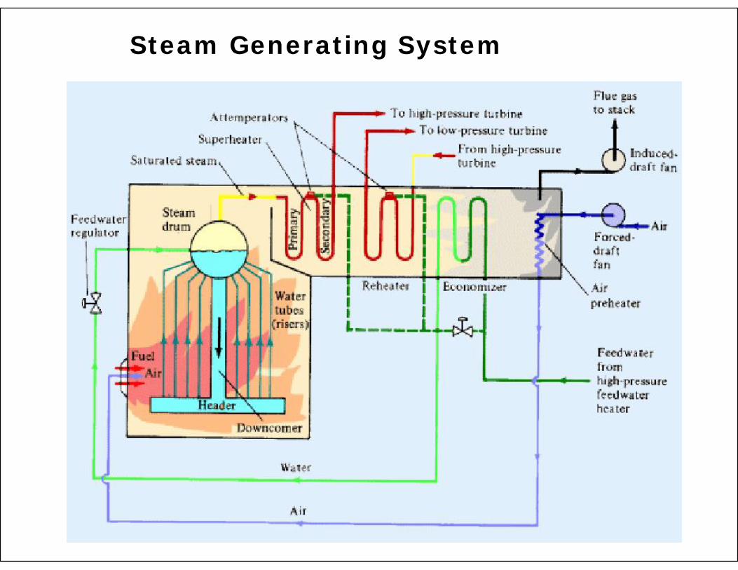
Steam Generating System

Water Circuit: Feed water & Boiler Circulating water
Fuel Circuit:
Combustion Air Circuit:
Flue Gas Circuit:
Steam Circuit:
Condensate Circuit:
Steam Generating System

Feed water circuit:
Deaerator:
Steam Generating System

Steam Generating System
Boiler circulation water :
Natural Circulation:

Steam Generating System
Boiler circulation water :
Forced Circulation:

Steam Generating System
Once Through Force Flow:

Nucleate Boiling :
Steam Generating System

Fuel Circuit:
Steam Generating System
Coal: Pulverizing PA Temperature
Oil: Viscosity Heating Atomizing Cleaning

Combustion Air Circuit:
Steam Generating System
Draught
Primary Air Secondary Air
Excess Air
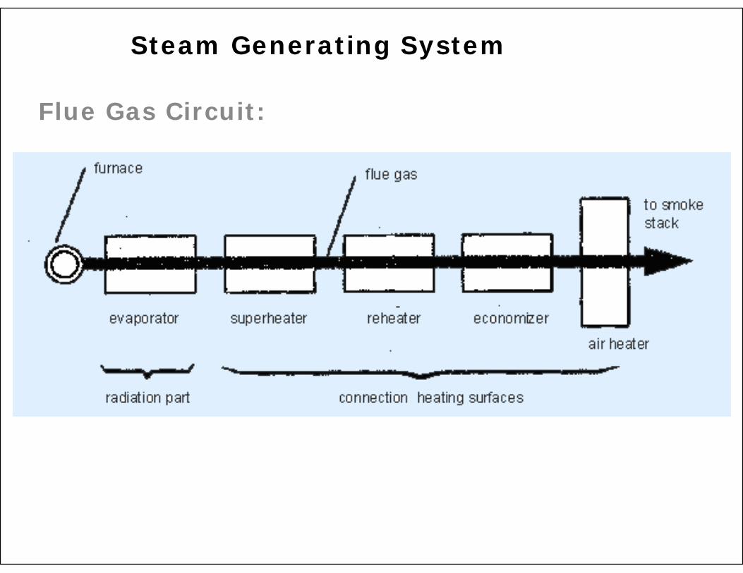
Flue Gas Circuit:
Steam Generating System
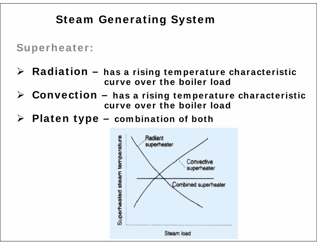
Superheater:
Steam Generating System
Radiation – has a rising temperature characteristic curve over the boiler load
Convection – has a rising temperature characteristic curve over the boiler load
Platen type – combination of both

Convection Heat Transfer:
Steam Generating System
Approach Point & Pinch Point:
Approach Point of Economizer - 10 to 15oC
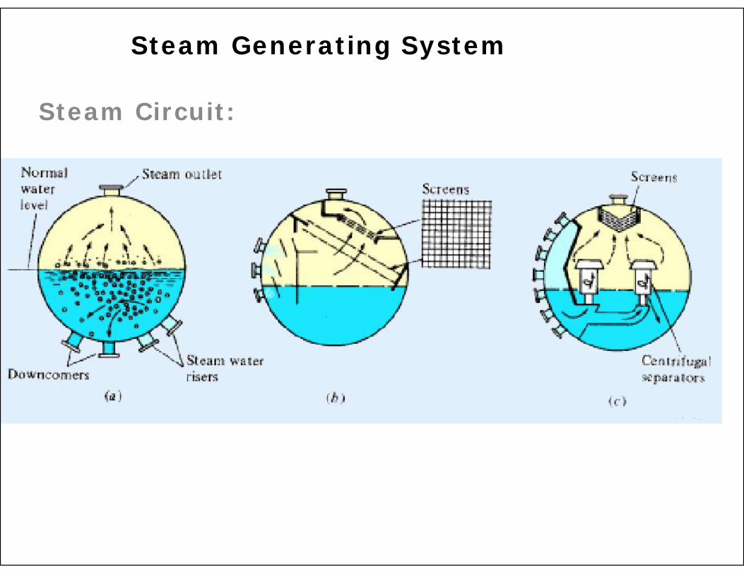
Steam Circuit:
Steam Generating System

Steam Separator:
Steam Generating System

Tangential Firing System Corner Windbox Arrangement


Tangential Firing System Arrangement(Joseph. G. Singer, 1981 )

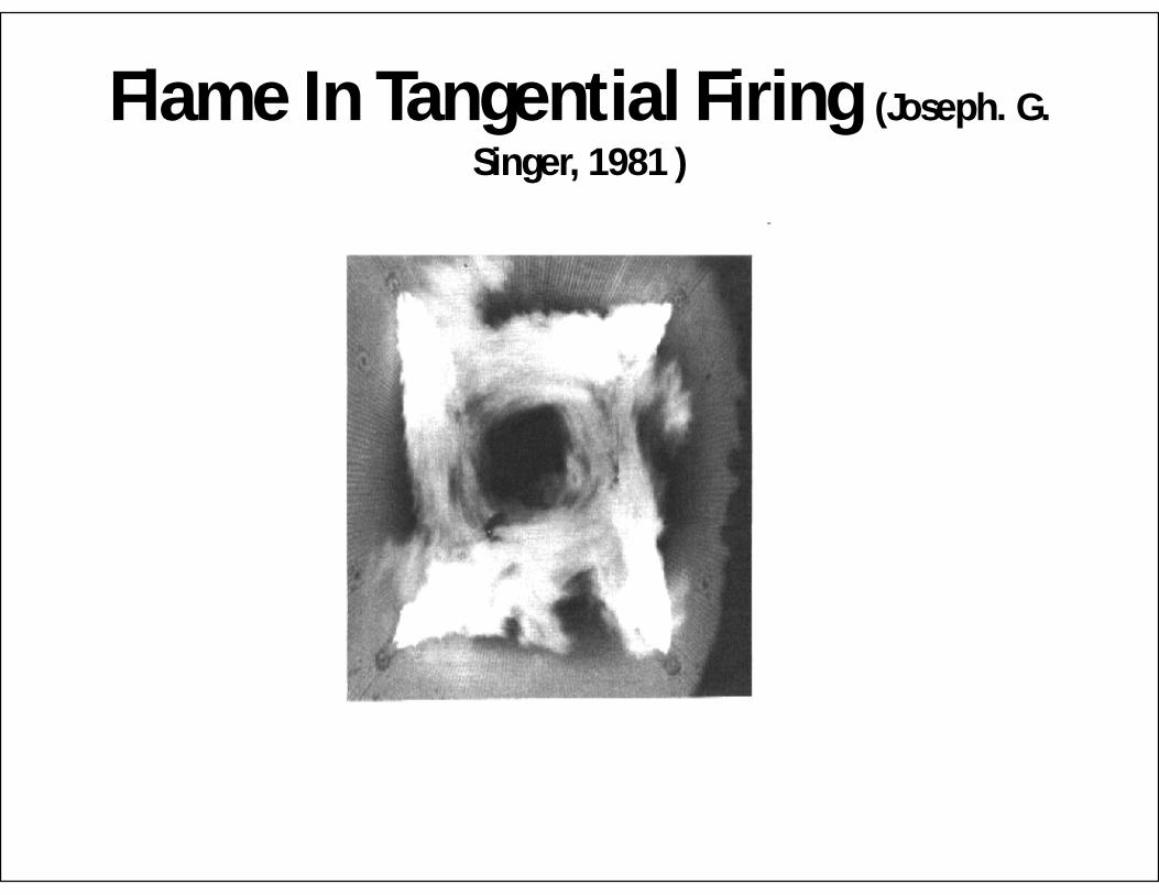
Flame In Tangential Firing (Joseph. G. Singer, 1981 )

10/30/2012 AADARSH 35

10/30/2012 AADARSH 36

10/30/2012 AADARSH 37

Trajectory Plot of Gas From Each Burner of 500 MW Coal Fired Boiler ( Hiroya Shida, 1984 )

Gas flow pattern in a 500 MW Boiler - Burners in Horizontal position
( Hiroya Shida, 1984 )

The Pattern of Recirculation In Tangentially Fired Boiler.
(Joseph. G. Singer, 1981 )

EXPLOSION
Ignition of an accumulated combustible mixture with in the combustion space of the Furnace or associated Boiler Passes,
Ducts and Fans that convey the flue gases to the Stack.
The intensity and magnitude of the explosion depends on both the relative quantity of combustible accumulated and
the proportion of air mixer.

FIRE TRIANGLE
FUEL
(Object)
OXYGEN(air)
HEAT
(Ignition temperature)
To start and sustain fire, Three items are required.
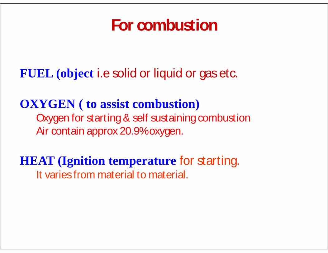
For combustion
FUEL (object i.e solid or liquid or gas etc.
OXYGEN ( to assist combustion)Oxygen for starting & self sustaining combustion Air contain approx 20.9% oxygen.
HEAT (Ignition temperature for starting. It varies from material to material.

FIRE EXTINGUISHING TRIANGLE
Cooling
BlanketingStarvation
Removal of one or more of the factors of the triangle of fire is the basic principle of fire presentation

10/30/2012 AADARSH 45
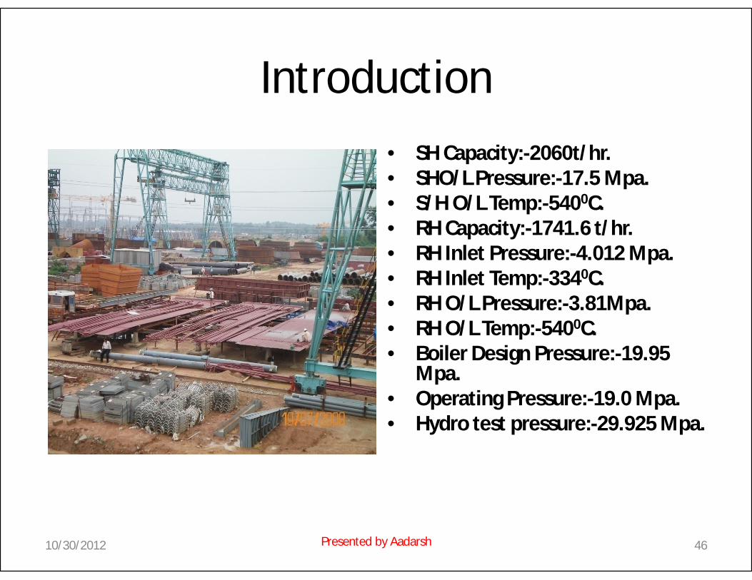
Introduction
• SH Capacity:-2060t/hr.• SHO/L Pressure:-17.5 Mpa.• S/H O/L Temp:-5400C.• RH Capacity:-1741.6 t/hr.• RH Inlet Pressure:-4.012 Mpa.• RH Inlet Temp:-3340C.• RH O/L Pressure:-3.81Mpa.• RH O/L Temp:-5400C.• Boiler Design Pressure:-19.95
Mpa.• Operating Pressure:-19.0 Mpa.• Hydro test pressure:-29.925 Mpa.
10/30/2012 46Presented by Aadarsh

1 1.Steam DrumBoiler Erection Sequence
10/30/2012 47Presented by Aadarsh

11.Steam Drum
2.Downcomer
2
Boiler Erection Sequence
10/30/2012 48Presented by Aadarsh

1
1.Steam Drum
2.Downcomer
3.Front w. wall along with hdrupto 17 mtr <R.
23
Boiler Erection Sequence
17 Mtr
Water wall with hdr. (Front)
10/30/2012 49Presented by Aadarsh
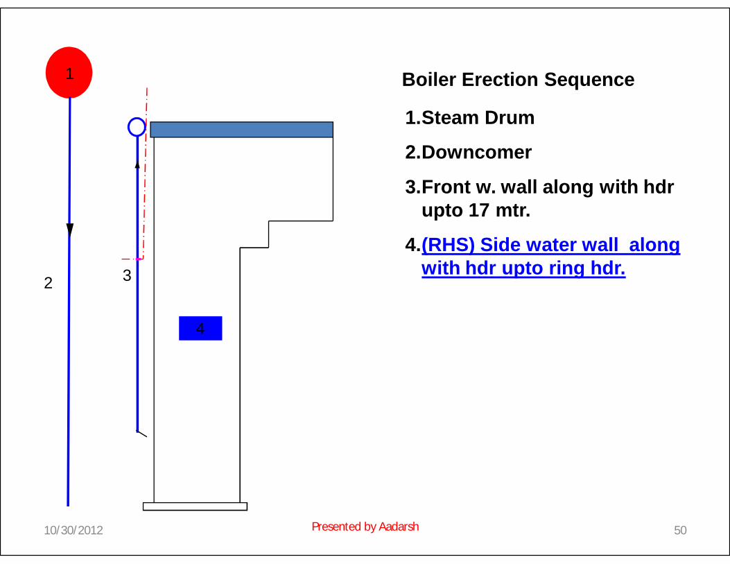
1
1.Steam Drum
2.Downcomer
3.Front w. wall along with hdrupto 17 mtr.
4.(RHS) Side water wall along with hdr upto ring hdr.3
Boiler Erection Sequence
4
2
10/30/2012 50Presented by Aadarsh

1
1.Steam Drum
2.Downcomer
3.Front w. wall along with hdrupto 17 mtr.
4.(RHS) Side water wall along with hdr upto ring hdr.
5.(LHS) Water wall up to 30 mtr. (For future approach for panel assembly)
3
Boiler Erection Sequence
52
5 (LHS) Water wall up to 30 Mtr.
10/30/2012 51Presented by Aadarsh

1
1.Steam Drum
2.Down comer
3.Front w. wall along with hdr upto 17 mtr.
4. (RHS) Side water wall along with hdr upto ring hdr.
5. (LHS) Water wall up to 30 mtr.
6.LHS BP Side wall.
3
Boiler Erection Sequence
5
6
4
2
10/30/2012 52Presented by Aadarsh

1
1.Steam Drum
2.Down comer
3.Front w. wall along with hdr upto 17 mtr.
4. (RHS) Side water wall along with hdr upto ring hdr.
5. (LHS) Water wall up to 30 mtr.
6.LHS BP Side wall.
7.Screen tube hdr along with screen tube.
3
Boiler Erection Sequence
5
6
4
2
7 Hdr along with screen tube.
10/30/2012 53Presented by Aadarsh
1
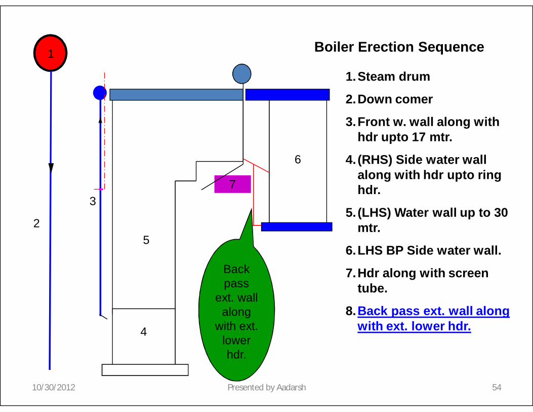
1.Steam drum
2.Down comer
3.Front w. wall along with hdr upto 17 mtr.
4. (RHS) Side water wall along with hdr upto ring hdr.
5. (LHS) Water wall up to 30 mtr.
6.LHS BP Side water wall.
7.Hdr along with screen tube.
8.Back pass ext. wall along with ext. lower hdr.
3
Boiler Erection Sequence
5
6
4
2
Back pass
ext. wall along
with ext. lower hdr.
7
10/30/2012 54Presented by Aadarsh

1
1.Steam drum
2.Down comer
3.Front w. wall along with hdr upto 17 mtr.
4. (RHS) Side water wall along with hdr upto ring hdr.
5. (LHS) Water wall up to 30 mtr.
6.LHS BP Side water wall.
7.Hdr along with screen tube.
8.Back pass ext. wall along with ext. lower hdr.
9. I/L & O/L FSH HDR.
3
Boiler Erection Sequence
5
6
4
2
8
9
7
10/30/2012 55Presented by Aadarsh

1
1.Steam drum
2.Down comer
3.Front w. wall along with hdr upto 17 mtr.
4. (RHS) Side water wall along with hdr upto ring hdr.
5. (LHS) Water wall up to 30 mtr.
6.LHS BP Side water wall.
7.Hdr along with screen tube.
8.Back pass ext. wall along with ext. lower hdr.
9. I/L & O/L FSH HDR.
10.FSH Coil.
3
Boiler Erection Sequence
5
6
4
2
8
9
10FSH Coils
7
10/30/2012 56Presented by Aadarsh

11.Steam Drum
2.Down Comer
3.Front w. wall along with hdr upto 17 mtr.
4. (RHS) Side water wall along with hdr upto ring hdr.
5. (LHS) Water wall up to 30 mtr.
6.LHS BP Side water wall.
7.Hdr along with screen tube.
8.Back pass ext. wall along with ext. lower hdr.
9. I/L & O/L FSH HDR.
10.FSH Coil.
11.Roof I/L Hdr.
3
Boiler Erection Sequence
5
6
4
2
8
9
1110
7
10/30/2012 57Presented by Aadarsh

1
1. Steam drum
2. Down comer
3. Front w. wall along with hdrupto 17 mtr.
4. (RHS) Side water wall along with hdr upto ring hdr.
5. (LHS) Water wall up to 30 mtr.
6. LHS BP Side water wall.
7. Hdr along with screen tube.
8. Back pass ext. wall along with ext. lower hdr.
9. I/L & O/L FSH HDR.
10.FSH Coil.
11.Roof I/L Hdr.
12.Roof O/L Hdr along with BP Front wall.
3
Boiler Erection Sequence
5
6
4
2
8
9
11
12
10
7
10/30/2012 58Presented by Aadarsh

1 1. Steam drum
2. Down comer
3. Front w. wall along with hdrupto 17 mtr.
4. (RHS) Side water wall along with hdr upto ring hdr.
5. (LHS) Water wall up to 30 mtr.
6. LHS BP Side water wall.
7. Hdr along with screen tube.
8. Back pass ext. wall along with ext. lower hdr.
9. I/L & O/L FSH HDR.
10.FSH Coil.
11.Roof I/L Hdr.
12.Roof O/L Hdr along with BP Front wall.
13.BP Rear wall.
3
Boiler Erection Sequence
5
6
4
2
8
9
11
12
10
13 BP Rear Wall
7
10/30/2012 59Presented by Aadarsh

1 1. Steam drum
2. Down comer
3. Front w. wall along with hdrupto 17 mtr.
4. (RHS) Side water wall along with hdr upto ring hdr.
5. (LHS) Water wall up to 30 mtr.
6. LHS BP Side water wall.
7. Hdr along with screen tube.
8. Back pass ext. wall along with ext. lower hdr.
9. I/L & O/L FSH HDR.
10.FSH Coil.
11.Roof I/L Hdr.
12.Roof O/L Hdr along with BP Front wall.
13.BP Rear wall.
14.ECO.Intermediate hdr,LTSH I/L Hdr & BP Ring Hdr.
3
Boiler Erection Sequence
5
6
4
2
8
9
11
12
10
13
14 ECO Inter.Hdr. 14
LTSH I/L Hdr.
14 Bottom ring hdr.
7
10/30/2012 60Presented by Aadarsh

1 1. Steam drum
2. Down comer
3. Front w. wall along with hdrupto 17 mtr.
4. (RHS) Side water wall along with hdr upto ring hdr.
5. (LHS) Water wall up to 30 mtr.
6. LHS BP Side water wall.
7. Hdr along with screen tube.
8. Back pass ext. wall along with ext. lower hdr.
9. I/L & O/L FSH HDR.
10.FSH Coil.
11.Roof I/L Hdr.
12.Roof O/L Hdr along with BP Front wall.
13.BP Rear wall.
14.ECO.Intermediate hdr,LTSH I/L Hdr & BP Ring Hdr.
15.BP Roof.
3
Boiler Erection Sequence
5
6
4
2
8
9
11
12
10
13
14.14
14.
157
10/30/2012 61Presented by Aadarsh

1 1. Steam drum
2. Down comer
3. Front w. wall along with hdr upto 17 mtr.
4. (RHS) Side water wall along with hdr upto ring hdr.
5. (LHS) Water wall up to 30 mtr.
6. LHS BP Side water wall.
7. Hdr along with screen tube.
8. Back pass ext. wall along with ext. lower hdr.
9. I/L & O/L FSH HDR.
10.FSH Coil.
11.Roof I/L Hdr.
12.Roof O/L Hdr along with BP Front wall.
13.BP Rear wall.
14.ECO.Intermediate hdr,LTSH I/L Hdr& BP Ring Hdr.
15.BP Roof.
16.LTSH O/L Hdr.
3
Boiler Erection Sequence
5
6
4
2
8
9
11
12
10
13
1414
14
15
167
10/30/2012 62Presented by Aadarsh
1 1. Steam drum
2. Down comer
3. Front w. wall along with hdr upto 17 mtr.
4. (RHS) Side water wall along with hdr upto ring hdr.
5. (LHS) Water wall up to 30 mtr.
6. LHS BP Side water wall.
7. Hdr along with screen tube.
8. Back pass ext. wall along with ext. lower hdr.
9. I/L & O/L FSH HDR.
10.FSH Coil.
11.Roof I/L Hdr.
12.Roof O/L Hdr along with BP Front wall.
13.BP Rear wall.
14.ECO.Intermediate hdr,LTSH I/L Hdr& BP Ring Hdr.
15.BP Roof.
16.LTSH O/L Hdr.
17.Ver.LTSH Panel, parallel crown plate.
3
Boiler Erection Sequence
5
6
4
2
8
9
11
12
10
13
1414
14
15
16
17
7
10/30/2012 63Presented by Aadarsh

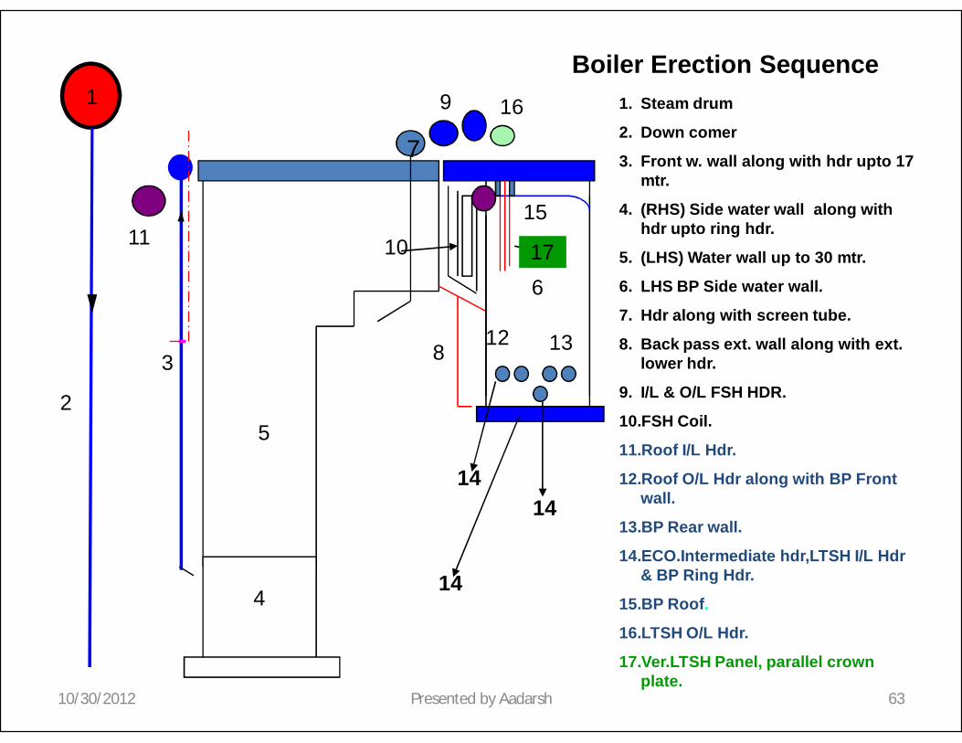
1 1. Steam drum
2. Down comer
3. Front w. wall along with hdr upto 17 mtr.
4. (RHS) Side water wall along with hdr upto ring hdr.
5. (LHS) Water wall up to 30 mtr.
6. LHS BP Side water wall.
7. Hdr along with screen tube.
8. Back pass ext. wall along with ext. lower hdr.
9. I/L & O/L FSH HDR.
10.FSH Coil.
11.Roof I/L Hdr.
12.Roof O/L Hdr along with BP Front wall.
13.BP Rear wall.
14.ECO.Intermediate hdr,LTSH I/L Hdr& BP Ring Hdr.
15.BP Roof.
16.LTSH O/L Hdr.
17.Ver.LTSH Panel.
18.ECO O/L Hdr.
3
Boiler Erection Sequence
5
6
4
2
8
9
11
12
10
13
1414
14
15
16
18
17
7
10/30/2012 64Presented by Aadarsh

1 1. Steam drum
2. Down comer
3. Front w. wall along with hdr upto 17 mtr.
4. (RHS) Side water wall along with hdrupto ring hdr.
5. (LHS) Water wall up to 30 mtr.
6. LHS BP Side water wall.
7. Hdr along with screen tube.
8. Back pass ext. wall along with ext. lower hdr.
9. I/L & O/L FSH HDR.
10.FSH Coil.
11.Roof I/L Hdr.
12.Roof O/L Hdr along with BP Front wall.
13.BP Rear wall.
14.ECO.Intermediate hdr,LTSH I/L Hdr & BP Ring Hdr.
15.BP Roof.
16.LTSH O/L Hdr.
17.Ver.LTSH Panel.
18.ECO O/L Hdr.
19.Eco.Hanger Tube along with Horz.LTSHCoil.
3
Boiler Erection Sequence
5
6
4
2
8
9
11
12
10
13
14
15
16
17
18
1414
19
7
10/30/2012 65Presented by Aadarsh

1 1. Steam drum
2. Down comer
3. Front w. wall along with hdr upto 17 mtr.
4. (RHS) Side water wall along with hdrupto ring hdr.
5. (LHS) Water wall up to 30 mtr.
6. LHS BP Side water wall.
7. Hdr along with screen tube.
8. Back pass ext. wall along with ext. lower hdr.
9. I/L & O/L FSH HDR.
10.FSH Coil.
11.Roof I/L Hdr.
12.Roof O/L Hdr along with BP Front wall.
13.BP Rear wall.
14.ECO.Intermediate hdr,LTSH I/L Hdr & BP Ring Hdr.
15.BP Roof.
16.LTSH O/L Hdr.
17.Ver.LTSH Panel.
18.ECO O/L Hdr.
19.Eco.Hanger Tube along with Horz.LTSHCoil.
20.ECO coil. & balance hanger tube erection.
3
Boiler Erection Sequence
5
6
4
2
7
8
9
11
12
10
13
15
16
17
18
1414
14
19
20
7
10/30/2012 66Presented by Aadarsh

1 1. Steam drum
2. Down comer
3. Front w. wall along with hdr upto 17 mtr.
4. (RHS) Side water wall along with hdr uptoring hdr.
5. (LHS) Water wall up to 30 mtr.
6. LHS BP Side wall.
7. Hdr along with screen tube.
8. Back pass ext. wall along with ext. lower hdr.
9. I/L & O/L FSH HDR.
10. FSH Coil.
11. Roof I/L Hdr.
12. Roof O/L Hdr along with BP Front wall.
13. BP Rear wall.
14. ECO.Intermediate hdr,LTSH I/L Hdr & BP Ring Hdr.
15. BP Roof.
16. LTSH O/L Hdr.
17. Ver.LTSH Panel.
18. ECO O/L Hdr.
19. Eco.Hanger Tube along with Horz.LTSHCoil.
20. ECO coil. & balance hanger tube erection.
21. ECO I/L Hdr after hopper comp & RHS BP Wall comp.
3
Boiler Erection Sequence
5
6
4
2
8
9
11 1110
12
15
16
17
18
14
14
19
20
21
6
7
10/30/2012 67Presented by Aadarsh

1
23
Boiler Erection Sequence
4 & 5
7
8
9
1011 12
13
19
20
21
14
15
1. Steam drum2. Down comer3. Front w. wall
along with hdr up to 17 mtr.
4. (RHS) Side water wall along with hdr up to ring hdr.
5. (LHS) Water wall up to 30 mtr.
6. LHS BP Side water wall.
7. Hdr along with screen tube.
8. Back pass ext. wall along with ext. lower hdr.
9. I/L & O/L FSH HDR.
10. FSH Coil.11. Roof I/L Hdr.12. Roof O/L Hdr
along with BP Front wall.
13. BP Rear wall.14. ECO.Intermediate
hdr,LTSH I/L Hdr& BP Ring Hdr.
15. BP Roof.16. LTSH O/L Hdr.17. Ver.LTSH Panel.18. ECO O/L Hdr.19. Eco.Hanger Tube
along with Horz.LTSH Coil.
20. ECO coil. & balance hanger tube erection.
21. ECO I/L Hdr.
17
13
13
17
7
10/30/2012 68Presented by Aadarsh

1
23
Boiler Erection Sequence
4 & 5
6
8
9
1011 12
13
19
20
21
15
16
1. Steam drum2. Down comer3. Front w. wall along
with hdr upto 17 mtr.4. (RHS) Side water wall
along with hdr uptoring hdr.
5. (LHS) Water wall up to 30 mtr.
6. LHS BP Side water wall.
7. Hdr along with screen tube.
8. Back pass ext. wall along with ext. lower hdr.
9. I/L & O/L FSH HDR.10. FSH Coil.11. Roof I/L Hdr.12. Roof O/L Hdr along
with BP Front wall.13. BP Rear wall.14. ECO.Intermediate
hdr,LTSH I/L Hdr & BP Ring Hdr.
15. BP Roof.16. LTSH O/L Hdr.17. Ver.LTSH Panel.18. ECO O/L Hdr.19. Eco.Hanger Tube
along with Horz.LTSHCoil.
20. ECO coil. & balance hanger tube erection.
21. ECO I/L Hdr.22. FRH Hdr.
7
22 FRH Hdr
18
14
14
17
10/30/2012 69Presented by Aadarsh

1
23
Boiler Erection Sequence
4 & 5
6
8
9
1011 12
13
19
20
21
14
15
1. Steam drum2. Down comer3. Front w. wall along
with hdr up to 17 mtr.4. (RHS) Side water wall
along with hdr up to ring hdr.
5. (LHS) Water wall up to 30 mtr.
6. LHS BP Side water wall.
7. Hdr along with screen tube.
8. Back pass ext. wall along with ext. lower hdr.
9. I/L & O/L FSH HDR.10. FSH Coil.11. Roof I/L Hdr.12. Roof O/L Hdr along
with BP Front wall.13. BP Rear wall.14. ECO.Intermediate
hdr,LTSH I/L Hdr & BP Ring Hdr.
15. BP Roof.16. LTSH O/L Hdr.17. Ver.LTSH Panel.18. ECO O/L Hdr.19. Eco.Hanger Tube
along with Horz.LTSHCoil.
20. ECO coil. & balance hanger tube erection.
21. ECO I/L Hdr.22. FRH Hdr.23. FRH crown plate.
7
22
23
13
13
18
17
10/30/2012 70Presented by Aadarsh

1
23
Boiler Erection Sequence
4 & 5
6
8
9
1011 12
13
19
20
21
15
16
1. Steam drum2. Down comer3. Front w. wall along
with hdr upto 17 mtr.4. (RHS) Side water wall
along with hdr uptoring hdr.
5. (LHS) Water wall up to 30 mtr.
6. LHS BP Side water wall.
7. Hdr along with screen tube.
8. Back pass ext. wall along with ext. lower hdr.
9. I/L & O/L FSH HDR.10. FSH Coil.11. Roof I/L Hdr.12. Roof O/L Hdr along
with BP Front wall.13. BP Rear wall.14. ECO.Intermediate
hdr,LTSH I/L Hdr & BP Ring Hdr.
15. BP Roof.16. LTSH O/L Hdr.17. Ver.LTSH Panel.18. ECO O/L Hdr.19. Eco.Hanger Tube
along with Horz.LTSHCoil.
20. ECO coil. & balance hanger tube erection.
21. ECO I/L Hdr..22. FRH Hdr.23. FRH crown plate.24. FRH coil.
7
22
23
24 FRH COIL
18
14
14
10/30/2012 71Presented by Aadarsh
1
23
Boiler Erection Sequence
4 & 5
6
8
9
1011 12
13
19
20
21
15
16
1. Steam drum2. Down comer3. Front w. wall along
with hdr up to 17 mtr.4. (RHS) Side water wall
along with hdr up to ring hdr.
5. (LHS) Water wall up to 30 mtr.
6. LHS BP Side water wall.
7. Hdr along with screen tube.
8. Back pass ext. wall along with ext. lower hdr.
9. I/L & O/L FSH HDR.10. FSH Coil.11. Roof I/L Hdr.12. Roof O/L Hdr along
with BP Front wall.13. BP Rear wall.14. ECO.Intermediate
hdr,LTSH I/L Hdr & BP Ring Hdr.
15. BP Roof.16. LTSH O/L Hdr.17. Ver.LTSH Panel.18. ECO O/L Hdr.19. Eco.Hanger Tube
along with Horz.LTSHCoil.
20. ECO coil. & balance hanger tube erection.
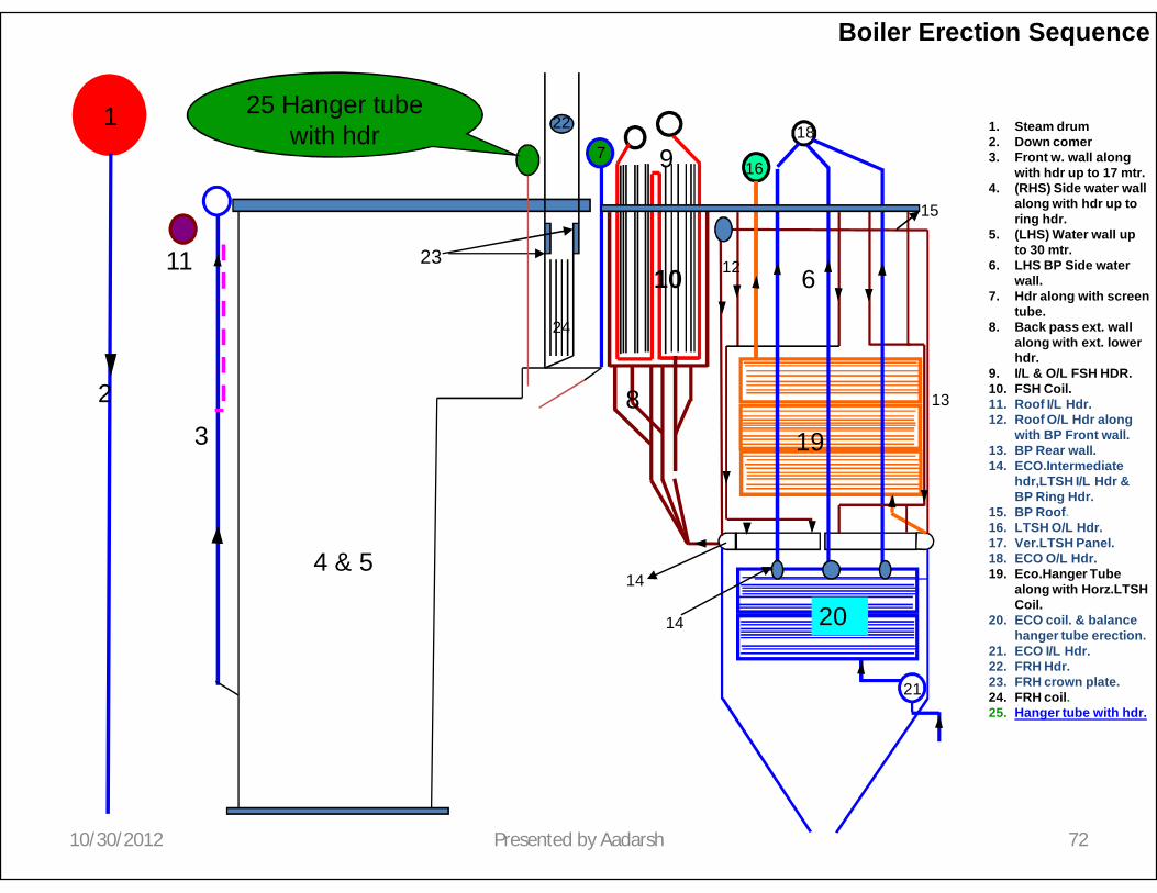
21. ECO I/L Hdr.22. FRH Hdr.23. FRH crown plate.24. FRH coil.25. Hanger tube with hdr.
7
22
23
18
14
14
24
25 Hanger tube with hdr
10/30/2012 72Presented by Aadarsh

1
23
Boiler Erection Sequence
4 & 5
6
8
9
1011 12
13
19
20
21
15
16
1. Steam drum2. Down comer3. Front w. wall along
with hdr up to 17 mtr.4. (RHS) Side water wall
along with hdr up to ring hdr.
5. (LHS) Water wall up to 30 mtr.
6. LHS BP Side water wall.
7. Hdr along with screen tube.
8. Back pass ext. wall along with ext. lower hdr.
9. I/L & O/L FSH HDR.10. FSH Coil.11. Roof I/L Hdr.12. Roof O/L Hdr along
with BP Front wall.13. BP Rear wall.14. ECO.Intermediate
hdr,LTSH I/L Hdr & BP Ring Hdr.
15. BP Roof.16. LTSH O/L Hdr.17. Ver.LTSH Panel.18. ECO O/L Hdr.19. Eco.Hanger Tube
along with Horz.LTSHCoil.
20. ECO coil. & balance hanger tube erection.
21. ECO I/L Hdr.22. FRH Hdr.23. FRH crown plate.24. FRH coil.25. Hanger tube with hdr.26. Rear arch.
7
22
23
18
14
14
24
25
26 Rear Arch.
10/30/2012 73Presented by Aadarsh

1
23
Boiler Erection Sequence
4 & 5
6
8
9
1011 12
13
19
20
21
15
16
1. Steam drum2. Down comer3. Front w. wall along
with hdr up to 17 mtr.4. (RHS) Side water wall
along with hdr up to ring hdr.
5. (LHS) Water wall up to 30 mtr.
6. LHS BP Side water wall.
7. Dr along with screen tube.
8. Back pass ext. wall along with ext. lower hdr.
9. I/L & O/L FSH HDR.10. FSH Coil.11. Roof I/L Hdr.12. Roof O/L Hdr along
with BP Front wall.13. BP Rear wall.14. ECO.Intermediate
hdr,LTSH I/L Hdr & BP Ring Hdr.
15. BP Roof.16. LTSH O/L Hdr.17. Ver.LTSH Panel.18. ECO O/L Hdr.19. Eco.Hanger Tube
along with Horz.LTSHCoil.
20. ECO coil. & balance hanger tube erection.
21. ECO I/L Hdr.22. FRH Hdr.23. FRH crown plate.24. FRH coil.25. Hanger tube with hdr.26. Rear arch.27. Rear water wall.
7
22
23
18
14
14
24
25
26
27 Rear w.wall
17
10/30/2012 74Presented by Aadarsh
1
23
Boiler Erection Sequence
4 & 5
6
8
9
1011 12
13
19
20
21
15
16
1. Steam drum2. Down comer3. Front w. wall along
with hdr up to 17 mtr.4. (RHS) Side water wall
along with hdr up to ring hdr.
5. (LHS) Water wall up to 30 mtr.
6. LHS BP Side water wall.
7. Hdr along with screen tube.
8. Back pass ext. wall along with ext. lower hdr.
9. I/L & O/L FSH HDR.10. FSH Coil.11. Roof I/L Hdr.12. Roof O/L Hdr along
with BP Front wall.13. BP Rear wall.14. ECO.Intermediate
hdr,LTSH I/L Hdr & BP Ring Hdr.
15. BP Roof.16. LTSH O/L Hdr.17. Ver.LTSH Panel.18. ECO O/L Hdr.19. Eco.Hanger Tube
along with Horz.LTSHCoil.
20. ECO coil. & balance hanger tube erection.
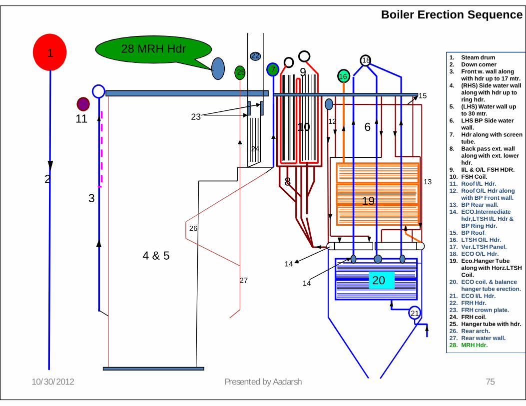
21. ECO I/L Hdr.22. FRH Hdr.23. FRH crown plate.24. FRH coil.25. Hanger tube with hdr.26. Rear arch.27. Rear water wall.28. MRH Hdr.
7
22
23
18
14
14
24
25
26
27
28 MRH Hdr
10/30/2012 75Presented by Aadarsh
1
23
Boiler Erection Sequence
4 & 5
6
8
9
1011 12
13
19
20
21
15
16
1. Steam drum2. Down comer3. Front w. wall along
with hdr up to 17 mtr.4. (RHS) Side water wall
along with hdr up to ring hdr.
5. (LHS) Water wall up to 30 mtr.
6. LHS BP Side water wall.
7. Hdr along with screen tube.
8. Back pass ext. wall along with ext. lower hdr.
9. I/L & O/L FSH HDR.10. FSH Coil.11. Roof I/L Hdr.12. Roof O/L Hdr along
with BP Front wall.13. BP Rear wall.14. ECO.Intermediate
hdr,LTSH I/L Hdr & BP Ring Hdr.
15. BP Roof.16. LTSH O/L Hdr.17. Ver.LTSH Panel.18. ECO O/L Hdr.19. Eco.Hanger Tube
along with Horz.LTSHCoil.
20. ECO coil. & balance hanger tube erection.
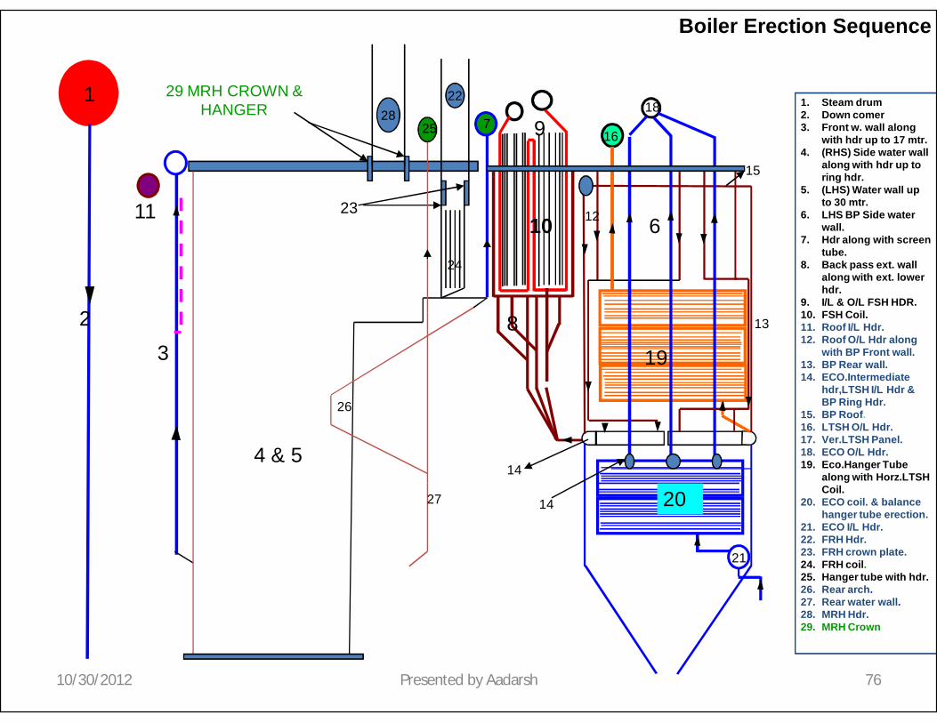
21. ECO I/L Hdr.22. FRH Hdr.23. FRH crown plate.24. FRH coil.25. Hanger tube with hdr.26. Rear arch.27. Rear water wall.28. MRH Hdr.29. MRH Crown
7
22
23
18
14
14
24
25
26
27
28
29 MRH CROWN & HANGER
10/30/2012 76Presented by Aadarsh

1
23
Boiler Erection Sequence
4 & 5
6
8
9
1011 12
13
19
20
21
15
16
1. Steam drum2. Down comer3. Front w. wall along
with hdr up to 17 mtr.4. (RHS) Side water wall
along with hdr up to ring hdr.
5. (LHS) Water wall up to 30 mtr.
6. LHS BP Side water wall.
7. Hdr along with screen tube.
8. Back pass ext. wall along with ext. lower hdr.
9. I/L & O/L FSH HDR.10. FSH Coil.11. Roof I/L Hdr.12. Roof O/L Hdr along
with BP Front wall.13. BP Rear wall.14. ECO.Intermediate
hdr,LTSH I/L Hdr & BP Ring Hdr.
15. BP Roof.16. LTSH O/L Hdr.17. Ver.LTSH Panel.18. ECO O/L Hdr.19. Eco.Hanger Tube
along with Horz.LTSHCoil.
20. ECO coil. & balance hanger tube erection.
21. ECO I/L Hdr.22. FRH Hdr.23. FRH crown plate.24. FRH coil.25. Hanger tube with hdr.26. Rear arch.27. Rear water wall.28. MRH Hdr.29. MRH Crown30. MRH Coil.
7
22
23
18
13
13
24
25
26
27
2829
30 MRH Coil
10/30/2012 77Presented by Aadarsh

1
23
Boiler Erection Sequence
4 & 5
6
8
9
1011 12
13
19
20
21
15
16
1. Steam drum2. Down comer3. Front w. wall along
with hdr up to 17 mtr.4. (RHS) Side water wall
along with hdr up to ring hdr.
5. (LHS) Water wall up to 30 mtr.
6. LHS BP Side water wall.
7. Hdr along wiyhscreen tube.
8. Back pass ext. wall along with ext. lower hdr.
9. I/L & O/L FSH HDR.10. FSH Coil.11. Roof I/L Hdr.12. Roof O/L Hdr along
with BP Front wall.13. BP Rear wall.14. ECO.Intermediate
hdr,LTSH I/L Hdr & BP Ring Hdr.
15. BP Roof.16. LTSH O/L Hdr.17. Ver.LTSH Panel.18. ECO O/L Hdr.19. Eco.Hanger Tube
along with Horz.LTSHCoil.
20. ECO coil. & balance hanger tube erection.
21. ECO I/L Hdr.22. FRH Hdr.23. FRH crown plate.24. FRH coil.25. Hanger tube with hdr.26. Rear arch.27. Rear water wall.28. MRH Hdr.29. MRH Crown30. MRH Coil.31. Link Pipe for
platen,FSH & ECO Link to Drum.
7
22
23
18
14
14
24
25
26
27
2829
30
31
10/30/2012 78Presented by Aadarsh
1
23
Boiler Erection Sequence
4 & 5
6
8
9
1011 12
13
19
20
21
15
16
1. Steam drum2. Down comer3. Front w. wall along
with hdr up to 17 mtr.4. (RHS) Side water wall
along with hdr up to ring hdr.
5. (LHS) Water wall up to 30 mtr.
6. LHS BP Side water wall.
7. Hdr along with screen tube.
8. Back pass ext. wall along with ext. lower hdr.
9. I/L & O/L FSH HDR.10. FSH Coil.11. Roof I/L Hdr.12. Roof O/L Hdr along
with BP Front wall.13. BP Rear wall.14. ECO.Intermediate
hdr,LTSH I/L Hdr & BP Ring Hdr.
15. BP Roof.16. LTSH O/L Hdr.17. Ver.LTSH Panel.18. ECO O/L Hdr.19. Eco.Hanger Tube
along with Horz.LTSHCoil.
20. ECO coil. & balance hanger tube erection.
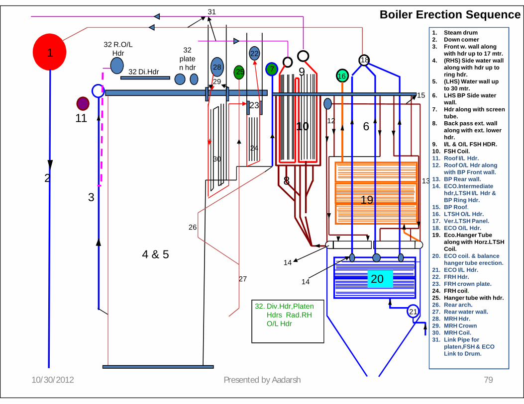
21. ECO I/L Hdr.22. FRH Hdr.23. FRH crown plate.24. FRH coil.25. Hanger tube with hdr.26. Rear arch.27. Rear water wall.28. MRH Hdr.29. MRH Crown30. MRH Coil.31. Link Pipe for
platen,FSH & ECO Link to Drum.
7
22
23
18
14
14
24
25
26
27
28
29
30
31
32 R.O/L Hdr
32 Di.Hdr
32 platen hdr
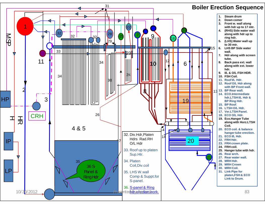
32. Div.Hdr,PlatenHdrs Rad.RHO/L Hdr
10/30/2012 79Presented by Aadarsh

1
23
Boiler Erection Sequence
4 & 5
6
8
9
1011 12
13
19
20
21
15
16
1. Steam Drum2. Down comer3. Front w. wall along
with hdr up to 17 mtr.4. (RHS) Side water wall
along with hdr up to ring hdr.
5. (LHS) Water wall up to 30 mtr.
6. LHS BP Side water wall.
7. Hdr along with screen tube.
8. Back pass ext. wall along with ext. lower hdr.
9. I/L & O/L FSH HDR.10. FSH Coil.11. Roof I/L Hdr.12. Roof O/L Hdr along
with BP Front wall.13. BP Rear wall.14. ECO.Intermediate
hdr,LTSH I/L Hdr & BP Ring Hdr.
15. BP Roof.16. LTSH O/L Hdr.17. Ver.LTSH Panel.18. ECO O/L Hdr.19. Eco.Hanger Tube
along with Horz.LTSHCoil.
20. ECO coil. & balance hanger tube erection.
21. ECO I/L Hdr.22. FRH Hdr.23. FRH crown plate.24. FRH coil.25. Hanger tube with hdr.26. Rear arch.27. Rear water wall.28. MRH Hdr.29. MRH Crown30. MRH Coil.31. Link Pipe for
platen,FSH & ECO Link to Drum.
7
22
23
18
14
14
24
25
26
27
28
29
30
31
3232 32
32. Div.Hdr,PlatenHdrs Rad.RHO/L Hdr
33. Roof up to platen Sup.Htr.
33 roof up to
platen sup.htr
10/30/2012 80Presented by Aadarsh

1
23
Boiler Erection Sequence
4 & 5
6
8
9
1011 12
13
19
20
21
15
16
1. Steam drum2. Down comer3. Front w. wall along
with hdr up to 17 mtr.4. (RHS) Side water wall
along with hdr up to ring hdr.
5. (LHS) Water wall up to 30 mtr.
6. LHS BP Side water wall.
7. Hdralong with screen tube.
8. Back pass ext. wall along with ext. lower hdr.
9. I/L & O/L FSH HDR.10. FSH Coil.11. Roof I/L Hdr.12. Roof O/L Hdr along
with BP Front wall.13. BP Rear wall.14. ECO.Intermediate
hdr,LTSH I/L Hdr & BP Ring Hdr.
15. BP Roof.16. LTSH O/L Hdr.17. Ver.LTSH Panel.18. ECO O/L Hdr.19. Eco.Hanger Tube
along with Horz.LTSHCoil.
20. ECO coil. & balance hanger tube erection.
21. ECO I/L Hdr.22. FRH Hdr.23. FRH crown plate.24. FRH coil.25. Hanger tube with hdr.26. Rear arch.27. Rear water wall.28. MRH Hdr.29. MRH Crown30. MRH Coil.31. Link Pipe for
platen,FSH & ECO Link to Drum.
7
22
23
18
14
14
24
25
26
27
28
29
30
31
3232 32
32. Div.Hdr,PlatenHdrs Rad.RHO/L Hdr
33. Roof up to platen Sup.Htr.
34. Platen Coil,Div.coil
34 Div.Coil
33
34 platen Coil
10/30/2012 81Presented by Aadarsh

1
23
Boiler Erection Sequence
4 & 5
6
8
9
1011 12
13
19
20
21
14
16
1. Steam drum2. Down comer3. Front w. wall along
with hdr up to 17 mtr.4. (RHS) Side water wall
along with hdr up to ring hdr.
5. (LHS) Water wall up to 30 mtr.
6. LHS BP Side water wall.
7. Hdr along with screen tube.
8. Back pass ext. wall along with ext. lower hdr.
9. I/L & O/L FSH HDR.10. FSH Coil.11. Roof I/L Hdr.12. Roof O/L Hdr along
with BP Front wall.13. BP Rear wall.14. ECO.Intermediate
hdr,LTSH I/L Hdr & BP Ring Hdr.
15. BP Roof.16. LTSH O/L Hdr.17. Ver.LTSH Panel.18. ECO O/L Hdr.19. Eco.Hanger Tube
along with Horz.LTSHCoil.
20. ECO coil. & balance hanger tube erection.
21. ECO I/L Hdr.22. FRH Hdr.23. FRH crown plate.24. FRH coil.25. Hanger tube with hdr.26. Rear arch.27. Rear water wall.28. MRH Hdr.29. MRH Crown30. MRH Coil.31. Link Pipe for
platen,FSH & ECO Link to Drum.
7
22
23
18
14
14
24
25
26
27
28
29
30
31
3232 32
32. Div.Hdr,PlatenHdrs Rad.RH O/L Hdr
33. Roof up to platen Sup.Htr.
34. Platen Coil,Div.coil
35. LHS W.wall Comp & Suppt.for S-panel.
34
33
34
35 LHS Balance w.wall & support.
10/30/2012 82Presented by Aadarsh
1
23
Boiler Erection Sequence
4 & 5
6
8
9
1011 12
13
19
20
21
15
16
1. Steam drum2. Down comer3. Front w. wall along
with hdr up to 17 mtr.4. (RHS) Side water wall
along with hdr up to ring hdr.
5. (LHS) Water wall up to 30 mtr.
6. LHS BP Side water wall.
7. Hdr along with screen tube.
8. Back pass ext. wall along with ext. lower hdr.
9. I/L & O/L FSH HDR.10. FSH Coil.11. Roof I/L Hdr.12. Roof O/L Hdr along
with BP Front wall.13. BP Rear wall.14. ECO.Intermediate
hdr,LTSH I/L Hdr & BP Ring Hdr.
15. BP Roof.16. LTSH O/L Hdr.17. Ver.LTSH Panel.18. ECO O/L Hdr.19. Eco.Hanger Tube
along with Horz.LTSHCoil.
20. ECO coil. & balance hanger tube erection.
21. ECO I/L Hdr.22. FRH Hdr.23. FRH crown plate.24. FRH coil.25. Hanger tube with hdr.26. Rear arch.27. Rear water wall.28. MRH Hdr.29. MRH Crown30. MRH Coil.31. Link Pipe for
platen,FSH & ECO Link to Drum.
7
22
23
18
14
14
24
25
26
27
28
29
30
31
3232 32
32. Div.Hdr,PlatenHdrs Rad.RHO/L Hdr
33. Roof up to platen Sup.Htr.
34. Platen Coil,Div.coil
35. LHS W.wallComp & Suppt.forS-panel.
36. S-panel & Ring hdr erection work.
34
33
34
35
IP
LP
HP
CRH
36 S-Panel & Ring Hdr
MSP
HR
H
10/30/2012 83Presented by Aadarsh

1. Steam Drum2. Downcomer3. Front w. wall along with hdr up to 17 mtr.4. (RHS) Side water wall along with hdr up
to ring hdr.5. (LHS )Side water wall along with hdr up
to 30 MTR.6. LHS BP Wall.7. Hdr along with screen tube.8. Back pass ext. wall along with ext. lower
hdr.9. I/L & O/L FSH HDR.10. FSH Coil .11. Roof I/L Hdr.12. Roof O/L Hdr along with BP Front wall.13. BP Rear wall .14. ECO. Intermediate Hdr 4 no, LTSH I/L HDR
& BP Ring Hdr.15. BP Roof.16. LTSH O/L Hdr.17. Ver. LTSH panel.
18. Eco. O/l hdr.19. Eco Coil with balance hanger tube.20. Eco I/L Hdr.21. FRH crown plate.22. FRH COIL.23. Hanger tube with Hdr.24. Rear arch.25. Rear water wall.26. MRH Hdr.27. MRH CROWN.28. MRH coil.29. LINK PIPE for platen , FSH & ECO LINK to
drum.30. Div. HDR, PLATEN HDRS & Rad. RH O/L
HDR.31. ROOF up to platen super heater.32. Platen coil & Div.coil.33. LHS W. wall completion & Bottom support.34. S-Panel & Ring Hdr Erection work.
10/30/2012 84Presented by Aadarsh

10/30/2012 AADARSH 85
BOILER DRUM
10/30/2012 AADARSH 86
Click here for Drum Lifting

CALCULATION FOR THE BOILER PRESSURE PARTS
10/30/2012 AADARSH 87
4x600 MW was one of the first of its kind in India.
SEL have erected India’s First Sub crtical Boiler Drum in unit # 2.
In order to ensure the safety of boiler , calculation of the boiler pressure parts was mandatory and we have done the calculation for pressure parts as per IBR.

10/30/2012 AADARSH 88
WORKING PRESSURE CALCULATION OF DRUM AS PER IBR:
D1:- ID = 1749mmOD = 2103mm
Th = 188mm / 177.4mm(Plate used)/(Actual)
D2:- ID = 1778mmOD = 2074mmTh = 153mm / 148mm
(Plate used)/(Actual)
Design temperature: 360 ˚CDesign Pressure: 19.95MpaWorking Pressure: 19Mpa (As per Form III)
Ligament efficiency ‘e’ = 0.862
YS at 370 ˚C at P/36 of IBR folder is 290 Mpa
Working metal temp. : 370 ˚CHence,
f = 290/ 1.5 = 193.33 Mpa

10/30/2012 AADARSH 89
Working Pressure =
= 25.49 Mpa and Hence Safe
Click here for boiler pressure parts calculation

10/30/2012 AADARSH 90
ECONOMISER

STEEL H ECONOMISERS
ADVANTAGES
HOW STEEL H IS PRODUCED
CASE STUDIES
WHAT IS STEEL H
SUPPLY OPTIONS
FUELS/BOILERS

STEEL H is an extended fin tube on Machines designed and built in house to our own specification.
STEEL H EXTENDED SURFACE TUBE
Named Steel H because the original fin resembledThe capital letter
‘H’

STEEL H PLATE FIN
• In Line Tube Arrangement with Straight Gas Passages Ensure Low Fouling and Sustained High Efficiency with Dirty Fuels
• More Effective Sootblowing• Compact Size• Low Pressure Loss• Less Tubes and Weight• Lower Boiler Costs• Proven Heat Transfer Rates• Double ‘H’ Inherent Stiffness
STEEL H ADVANTAGES

15.4632.4 42.13
87.54 96.78
0
50
100Heating
Surface
[ m2 ]
Heating Surface AreaM2 in 1 Cubic Metre of Space.
PS CFS HF Steel H Double Stl HSingle steel H
Helical Fin

1515
15
30 30
15 155 510
2020
30 30
10
20 20
35
20
30
30
20
35
35 35
35
30
20
20
30
35
GAS FLOW Fins placed in areas of highestheat transfer.
Fin weld on sides of tubewhere maximum heattransfer takes place.
Fin material not placed wheredust can accumulate aboveand below the tube.
Fin sizes optimised forefficient use of material.
STEEL H DESIGN

WeldCurrent
ForgePressure
• Fins are held in the correct position by Jaws.
• Current and forge pressure is applied to weld fins to tube.
• Tube is precisely indexed forward for next fin weld.
STEEL H PRODUCTION
STEEL H PRODUCTION
WeldCurrent
ForgePressure

PRECISE INDEXING

10/30/2012 AADARSH 98

RE HEATER CIRCUIT
NON DRAINABLE PORTION
DRAINABLE PORTION
M.S

Water and Steam flow Circuit
10/30/2012 AADARSH 100
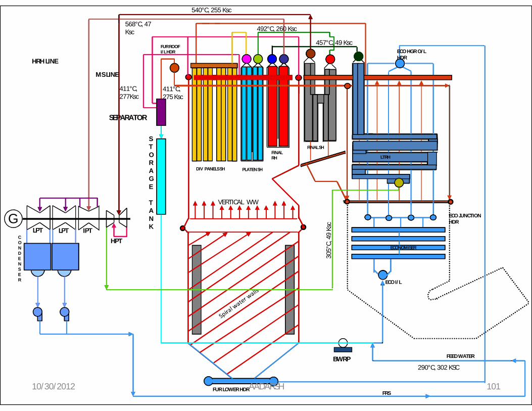
HPT
IPTLPTCONDENSER
FEED WATER
FRS
STORAGE
TANK
SEPARATOR
BWRP
MS LINE
HRH LINE
VERTICAL WW
ECO I/L
ECO JUNCTION HDR
ECO HGR O/L HDR
FUR LOWER HDR
FUR ROOF I/L HDR
DIV PANELS SH PLATEN SH
FINAL RH
FINAL SH
LTRH
ECONOMISER
290°C, 302 KSC
411°C, 277Ksc
411°C, 275 Ksc
492°C, 260 Ksc
540°C, 255 Ksc
305°
C, 4
9 Ks
c
457°C, 49 Ksc
568°C, 47 Ksc
GLPT
10/30/2012 AADARSH 101

10/30/2012 AADARSH 102

10/30/2012 AADARSH 103

10/30/2012 AADARSH 104
Click Here

10/30/2012 AADARSH 105
Click Here
10/30/2012 AADARSH 106
Click Here

10/30/2012 AADARSH 107

Why use an ESP ?
• To control atmospheric pollution caused by fly ash .
• To meet statutory requirement of pollution control (< 50mg/Nm3 as per Gazette notification by MoEF dated 150mg/Nm3 at 19.05.93).
• The byproduct- Fly ash can be utilized for applications like cement works, brick manufacturing etc.
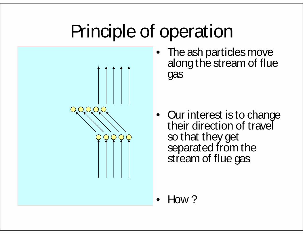
Principle of operation• The ash particles move
along the stream of flue gas
• Our interest is to change their direction of travel so that they get separated from the stream of flue gas
• How ?

Principle of operation (continued)• We impart electrical
charge to the particles.
• We have a surface with opposite electrical polarity nearby.
• The particles are electrically attracted to the surface.
+

Principle of operation (continued)• Emitting electrode is
charged at high voltage DC (negative).
• Collecting Electrode (plate) is at ground potential (positive).
+ -

Principle of operation (continued)• Emitting electrodes
sprays negative ions towards positive plate (corona discharge).
• They collide with ash particles and transfer the charge to them.
• Ash particles get negatively charged.
-+
-
-
--
- -
-
-
-
--

Principle of operation (continued)• The positive collecting
plate attracts negative ash particles.
• On reaching the collecting plate, the particles get electrically neutralized and remain there.
+
-
-
-
-
-
-
-
-
-

Principle of operation (continued)
• After a layer of ash is collected on the collecting plate,it is mechanically rapped so that the ash falls into the hopper for disposal through ash handling system.
Construction
• To achieve laminar flow at lower velocity the gas path is split in several “Pass”es.
• Perforated GD screen at the entry of each pass ensure uniform velocity distribution.
• To achieve better collection efficiency several fields are provided in series in each pass.
• Many combinations are possible depending on boiler size.

Construction (major parts)
• Collecting plates
• Emitting electrodes
• Rapping mechanism (collecting,emitting)
• Insulators
• High Voltage Rectiformers
• Heaters
• Ash Level Indicators

ESP typical construction

Construction (collecting rapping)
• Type: Side driven flexible arm rapper
• Rapper control type-Microcomputer
• Hammers for each row of collecting plates are mounted at different angles on the rapper shaft.
• When the shaft rotates all rows get hammered one by one.
• Max no. of electrodes rapped by a rapper at a time- 2

Construction(hopper heaters)
• A portion of the hopper is double walled.
• Heaters (4.5 kW) are placed between the walls to keep the ash warm so that it does not stick to the sides of the hopper.
• Total No of Hoppers for one boiler- 50

Construction (insulator heaters)
• Shaft insulators and support insulators do not fall in regular gas flow path.
• They get colder and help ash accumulation on them. This reduces the field voltage.
• Heaters for individual insulators are used to keep them warm.

Construction(ash level indicators )
• Ash Level indicators are provided in each hopper for sensing hopper overfilled condition.
• High level trips the particular field.

Control philosophy
• To have a voltage just below the spark-over voltage for as long as possible.
• The controller measures current and calculates dI/dt .• When this value crosses a limit a spark is sensed.• Voltage is made zero for few milliseconds of pause time to
allow ionized air to flow away.• Voltage again rises at a fast rate to very near the spark over
value (say 90%).• Rate of rise then slows down.• If a spark is sensed, the process repeats itself.• If no spark is sensed, the voltage continues to rise till
voltage/current limit is reached.

Controller (graph)
V
t
Controller(back corona)
• All controllers use the above method of dynamic control of voltage.
• However use of only this method is unable to tackle the BACK CORONA problem.
• Modern controllers have micro-processor based computing facilities to take care of the back corona problem.

Controller(potential difference )
• The neutralization of charged ash particles constitute a current.
• Current has to pass through the layer of ash already collected.
• Potential difference is created across the layer. (V=IR)
+-
V = I x R

Controller(ionization of trapped air)
• Due to the high resistivity of ash the potential difference in a few mm thick layer can be several kV.
• This ionizes the air trapped between the ash layers.
+ ++
+
-
-
-

Controller(back corona)
• The positive ions are repelled by the positive plate & they come out in a stream.
• This phenomenon is BACK CORONA.
++ + +
+ + +
++
+

Controller(effects of back corona)
BACK CORONA• Neutralize charged ash
particles, so they are not collected.
• Dislodges already collected particles & allows them fly away.
• Draws extra power & reduces collection efficiency.
+-+
++

Controller(controlling back corona)
• To reduce Back Corona IR drop has to be reduced.
• R is a property of ash which cannot be controlled.
• To reduce I, V has to be reduced which will reduce the main corona. Hence collection itself will be reduced.

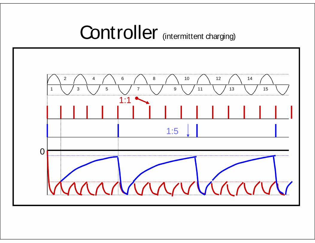
Controller (intermittent charging)
• Similar to a fluorescent tube, higher voltage is required to start a corona. Once started, the corona can be maintained by a much lesser voltage.
• The field behaves like a RC circuit. Once charged, the voltage decays only gradually through the collection current.
• It can be charged again before corona stops.

Controller (less average voltage)
• In conventional method of charging every half cycle, difference between the peak & average voltages is very small.
• In intermittent charging, firing of the thyristors is skipped for several half cycles & voltage is allowed to decay. While the peak voltage remains same, the average voltage comes down drastically.
Controller (intermittent charging)
0
1
2
3
4
5
6
7
8
9
10
11
12
13
14
15
1:5
1:1

Controller (less average current)
• Reduction of average voltage reduces average current which in turn reduces the IR drop across the ash layer. Thus back corona is controlled.
• The number of half cycles skipped is denoted by “charge ratio”. A charge ratio of 1:5 means firing takes place at every 5th half cycle.
• If we use charge ratio more than 1:5, the voltage becomes too low to sustain the main corona after the 5th half cycle.
• To avoid this thyristors are fired just before 180 deg from 6th half cycle onwards. This is called “BASE CHARGE”.
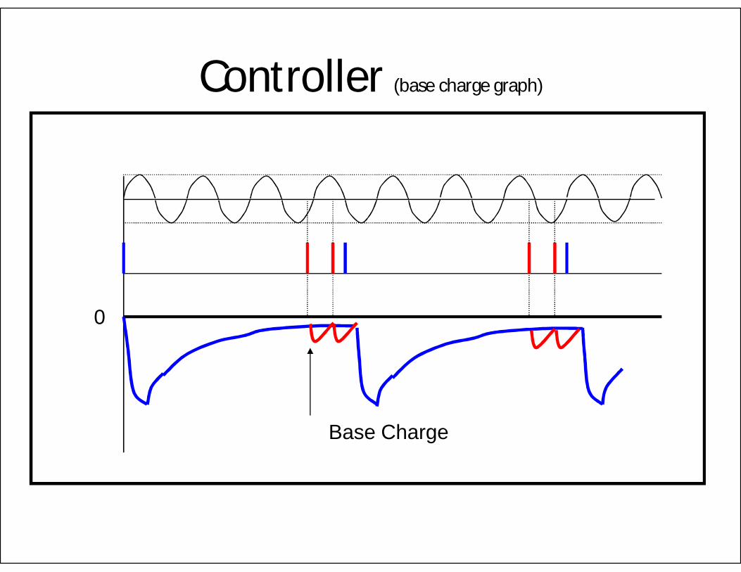
Controller (base charge graph)
Base Charge
0

10/30/2012 AADARSH 135

CONTENTSCONTENTS
1. The purpose of boiler life assessment
2. Life Evaluation by Inspection
3. Preparations for Inspection
4. Data requirement
5. Inspection of high pressure parts.
6. Sample tube inspection.
7. Visual inspection for other parts of boiler .
8. Water quality survey.
9. Visual Inspection for aux Equipment
10. high pressure parts Inspection details

THE PURPOSE OF BOILER LIFE ASSESSMENT • Evaluate the present state and the condition of the boiler components in order To
continue stable and reliable boiler operation
• Evaluate the remaining life for Superheater and Reheater by metallurgical inspection
• Evaluation of creep life and future inspection scheme by metallurgical inspection for water wall, economizer, Superheater and Reheater tubes
• Evaluation degree of creep damage for Superheater and Reheater by hardness test• Evaluate the remaining life based on thickness Measurement for water wall,
• Evaluate the remaining life based on thickness thinning for economizer due to low Temperature Corrosion,
• Evaluate the remaining life based on thickness thinning for Superheater and Reheater tubes due to high Temperature Corrosion
• Confirm the cause of the inner scale generation
• Evaluate the remaining life based on check of metal structure ,inner scale ,etc for sample tube
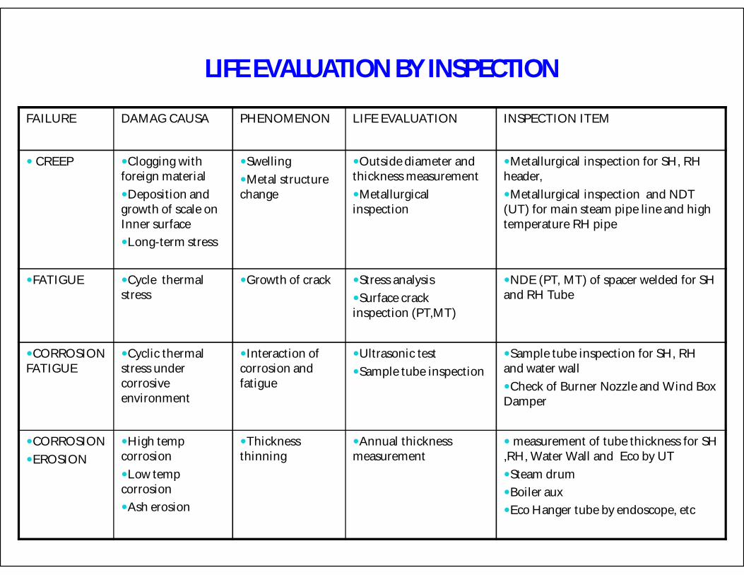
LIFE EVALUATION BY INSPECTION
FAILURE DAMAG CAUSA PHENOMENON LIFE EVALUATION INSPECTION ITEM
CREEP Clogging with foreign materialDeposition and growth of scale on Inner surfaceLong-term stress
SwellingMetal structure change
Outside diameter and thickness measurementMetallurgical inspection
Metallurgical inspection for SH, RH header,Metallurgical inspection and NDT (UT) for main steam pipe line and high temperature RH pipe
FATIGUE Cycle thermal stress
Growth of crack Stress analysisSurface crack inspection (PT,MT)
NDE (PT, MT) of spacer welded for SH and RH Tube
CORROSION FATIGUE
Cyclic thermal stress under corrosive environment
Interaction of corrosion and fatigue
Ultrasonic testSample tube inspection
Sample tube inspection for SH, RH and water wallCheck of Burner Nozzle and Wind Box Damper
CORROSIONEROSION
High temp corrosionLow temp corrosionAsh erosion
Thickness thinning
Annual thickness measurement
measurement of tube thickness for SH ,RH, Water Wall and Eco by UT Steam drumBoiler auxEco Hanger tube by endoscope, etc

PREPARATIONS FOR INSPECTION• Before inspection
– Superheater, reheater, economizer and water wall cleaning
– Air heater washing
– Scaffolding
– Removal of insulation
– Open man holes, inspection holes, flanges etc
• During inspection– Surface preparation of inspection parts
– Surface finishing (grinding) of inspection parts
– Instrument of apparatus of inspection
– Cutting tubes
– Welding tubes
• Material requirement– New tubes
– Man hole packing
– insulation
• Period of inspection– Two weeks

DATA REQUIREMENT
• Boiler reference data– Steam temperature 0c– Maximum Steam flow Ton/hr– Boiler design pressure Kgm/cm2
– Feed water temp 0c– Reheated inlet steam temperature 0c – Reheated outlet steam temperature 0c– Reheater design pressure Kgm/cm2
– Kind of fuel Gas, Oil
• Functional inspection with boiler in operation– Collection of drawings and main technical data– Recording of actual operating and functional data at different loads and
conditions at MCR and Verification of the operation of the boiler – Collection of data relevant to the thermal history and interventions ,if any
made on the boiler during his operation life

INSPECTION OF HIGH PRESSURE PARTS
• NON Destructive test for the following item1. Economizer headers, coils, Piping from economizer to steam drum,.2. Steam drum.3. Furnace water walls, screen, roof wall, feeders, riser ,Water walls headers.4. Saturation steam pipe.5. Primary, secondary super heater.6. Connecting pipe between primary superheater and secondary superheater.7. Reheater.8. Main SH steam pipes
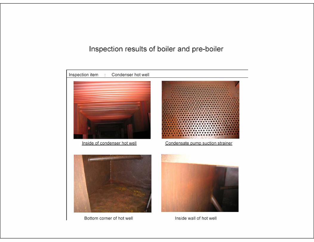
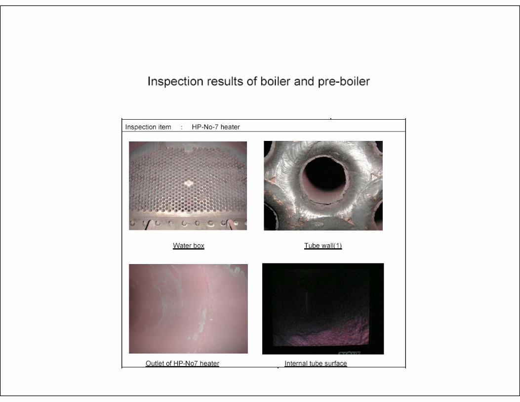
**Inspection item
1. External visual inspection2. Internal visual inspection with endoscope3. UT for thickness measurements by UT 4. MT and UT on circumferential welds5. MT on piping attachments6. Metallographic inspection by plastic replicas7. MT on nozzles welds of the coil tubes8. MT on nozzles welds to the shell of the inlet/outlet pipe

the minimum required thickness
t = minimum required thickness.D = outside diameter of cylinder.e = thickness factor for expanded tube ends.P = maximum allowable working pressure. S = maximum allowable stress value at the design temperature of the metal.

DESIGN / OPERATING INFORMATIONFOR CALCULATION OF REMAINING TIME BASED ON THICKNESS
• Design information– material type or grade– Nominal outside diameter– Designing pressure– Design life– Deign temperature– Original nominal thickness
• Operating information– Maximum tube metal
temperature– Normal operating pressure– Original measured minimum
thickness– Metal thinning rate
Thickness measurements of water wall tubes furnace

SAMPLE TUBE
Destructive test for the Sample tube For Water Wall ,SR and RH tubes
– Life diagnoses based on check of metal structure, thickness, inner scale, etc– Sample tube takes according to the result of hardness measurement
• Investigation Items– Visual inspection – Non destructive test– Chemical analysis– Measurement of the tube dimension– Hardness measurement– Cross sectional microstructure observation– Steam oxidation observation– Creep rupture test– Measurement of the inner scale thickness
• Information– Material of Sample tube– tube dimension

sample tubes
Thinning of bulged zone Internal surface scale External surface scale

Optical micrograph
Optical micrograph of non-bluged zones tube wall side showing ferrite –pearlite structure with no internal defects
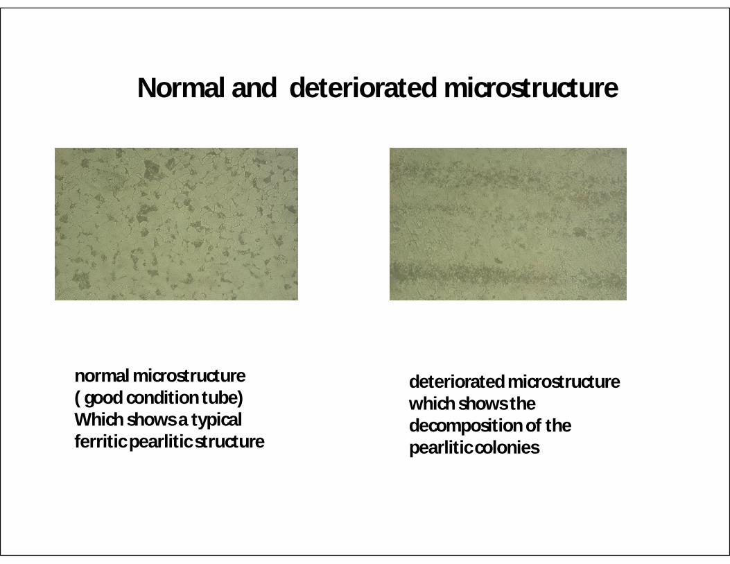
Normal and deteriorated microstructure
normal microstructure ( good condition tube) Which shows a typical ferritic pearlitic structure
deteriorated microstructure which shows the decomposition of the pearlitic colonies


7-Visual inspection for other parts of boiler
– Burner
– Wind Box
– Hanger for riser pipe
– Outer casing
– Skin casing
– Buckstay

WATER QUALITY SURVEY
This inspection to confirm the cause of the scale generation
• Inspection items
– Check of laboratory analysis method for quality items
– Confirmation of water quality results at previous load operation
– Check of instrument condition on sampling rack used for water quality control
– Confirmation of PH value and iron/copper balance in the cycle

VISUAL INSPECTION FOR AUX EQUIPMENT
This inspection to confirm the cause of the scale generation
– Condenser hot well.– Condenser tube side– Deaerator.– LP-feed water heater. – Feed water tank.– HP-feed water heater.

HIGH PRESSURE PARTS INSPECTION DETAILS
1. Economizer headers ,coils, Piping from economizer to steam drum,
2. Steam drum
3. Furnace water walls, screen, roof wall, feeders, riser ,Water walls headers
4. Saturation steam pipe5. Primary, secondary superheater
6. Connecting pipe between primary super heater and secondary superheater
7. Reheater
8. Main SH steam pipes

ECONOMIZER
• NDE For headers– External visual inspection– Internal visual inspection with endoscope– Measurement of thickness by UT
– MT on nozzles welds of the coil tubes and headers attachments– MT and UT on circumferential welds between header and conical pieces
• NDE For tube– External visual inspection– Measurement of economizer tube and hanger tube thickness with endoscope– UT for thickness measurements
• NDE For Piping from economizer to steam drum– External visual inspection for piping, hangers and supports– UT for thickness measurements– MT and UT on circumferential welds– MT on piping attachments– MT on the elbows extrados

STEAM DRUM
• Before the NDT inspections, the internal parts of the drum shall be dismantled
• NDE For steam drum– External visual inspection– Internal visual inspection– UT for shell thickness measurements– UT for head thickness measurements– MT and UT on circumferential and longitudinal welds– MT on steam drum attachments (saddles and accessories)– MT on nozzles welds
• NDE For downcomers– External visual inspection for piping, hangers and supports– UT for thickness measurements– MT and UT on circumferential welds– MT on piping attachments

FURNACE WATER WALLS, SCREEN, ROOF WALL, FEEDERS AND RISER
• NDE for furnace water walls, screen, roof wall– External visual inspection– UT for thickness measurements– Metallographic examination by plastic replicas– Samples for destructive test
• NDE for feeders and riser– External visual inspection– UT for thickness measurements
• NDE for headers – External visual inspection– Internal visual inspection with endoscope– UT for thickness measurements – MT on nozzles welds of the coil tubes– MT on branches welds and headers attachments, including drains tubes

SATURATION STEAM PIPE
• NDE for each pipe– External visual inspection
– UT for thickness measurements
– MT and UT on circumferential welds– MT on piping attachments
– MT on the elbows extrados
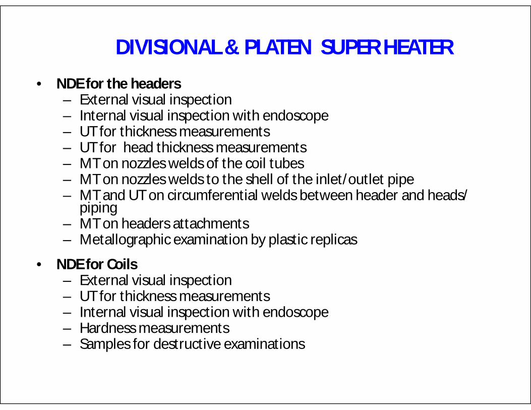
DIVISIONAL & PLATEN SUPER HEATER
• NDE for the headers– External visual inspection– Internal visual inspection with endoscope– UT for thickness measurements – UT for head thickness measurements– MT on nozzles welds of the coil tubes– MT on nozzles welds to the shell of the inlet/outlet pipe– MT and UT on circumferential welds between header and heads/
piping– MT on headers attachments– Metallographic examination by plastic replicas
• NDE for Coils– External visual inspection– UT for thickness measurements– Internal visual inspection with endoscope– Hardness measurements– Samples for destructive examinations

CONNECTING PIPE BETWEEN DIVISIONAL & PLATEN SUPERHEATER, DESUPERHEATER
• NDE for connecting pipe– External visual inspection– UT for thickness measurements – MT and UT on circumferential welds– MT on piping attachments– MT on the elbows extrados– Metallographic examination by plastic replicas
• NDE for desuperheater ATPS– External visual inspection– Internal visual inspection with endoscope– UT for thickness measurements– MT on circumferential welds– Metallographic examination by plastic replicas

REHEATER
• NDE For each one of the headers – External visual inspection– Internal visual inspection with endoscope– UT for thickness measurements – UT for head thickness measurements– MT on nozzles welds of the coil tubes– MT on nozzles welds to the shell of the inlet/outlet pipe– MT and UT on circumferential welds between header and heads/
piping– MT on headers attachments– Metallographic examination by plastic replicas
• NDE For Coils– External visual inspection– UT for thickness measurements– Internal visual inspection with endoscope– Hardness measurements– Samples for destructive examinations

MAIN SH STEAM PIPES
• NDE for each pipe– External visual inspection
– UT for thickness measurements
– MT and UT on circumferential welds– MT on piping attachments
– MT on the elbows extrados
– MT on nozzles welds to the pipe
– Metallographic examination by plastic replicas


10/30/2012 AADARSH 167


