© 2016 IJEDR | Volume 4, Issue 4 | ISSN: 2321-9939
IJEDR1604086 International Journal of Engineering Development and Research (www.ijedr.org) 589
A Voltage Controlled Mode Fact Devices for Power
Quality Improvement and Protection 1G. Mohan Babu, 2 V. Kalyani, 3J. Narender
1 Associate Professor, 2Assistant Professor, 3Assistant Professor
Department of Electrical & Electronics Engineering,
Princeton College of engineering & Technology, JNTU Hyderabad, India.
________________________________________________________________________________________________________
Abstract - In this thesis, proposes a new algorithm to generate reference voltage for a distribution static compensator
(DSTATCOM) operating in voltage-control mode. The proposed scheme exhibits several advantages compared to
traditional voltage-controlled DSTATCOM where the reference voltage is arbitrarily taken as 1.0 p.u. The proposed
scheme ensures that unity power factor (UPF) is achieved at the load terminal during nominal operation, which is not
possible in the traditional method. Also, the compensator injects lower currents and, therefore, reduces losses in the feeder
and voltage-source inverter. Further, a saving in the rating of DSTATCOM is achieved which increases its capacity to
mitigate voltage sag. Nearly UPF is maintained, while regulating voltage at the load terminal, during load change. The
state-space model of DSTATCOM is incorporated with the deadbeat predictive controller for fast load voltage regulation
during voltage disturbances. With these features, this scheme allows DSTATCOM to tackle power-quality issues by
providing power factor correction, harmonic elimination, load balancing, and voltage regulation based on the load
requirement. Simulation and experimental results are presented to demonstrate the efficiency of the proposed algorithm.
Index Terms – D-Statcom, PI Controller, Voltage Source Inverter, Voltage Source Converter, PSCAD. ________________________________________________________________________________________________________
I INTRODUCTION A Power quality problem is an occurrence manifested as a nonstandard voltage, current or frequency that results in a failure or a
disoperation of end user equipments. Utility distribution networks, sensitive industrial loads and critical commercial operations
suffer from various types of outages and service interruptions which can cost significant financial losses. With the restructuring of
power systems and with shifting trend towards distributed and dispersed generation, the issue of power quality is going to take
newer dimensions.
This work describes the techniques of correcting the supply voltage sag, swell and interruption in a distributed system.
At present, a wide range of very flexible controllers, which capitalize on newly available power electronics components, are
emerging for custom power applications. Among these, the distribution static compensator and the dynamic voltage restorer are
most effective devices, both of them based on the Voltage Source Converter (VSC) principle. A DVR injects a voltage in series
with the system voltage and a D-STATCOM injects a current into the system to correct the voltage sag, swell and interruption.
Comprehensive results are presented to assess the performance of each device as a potential custom power solution.
II LITERATURE REVIEW:
The various characteristics of voltage sags experienced by customers within industrial distribution systems. Special
emphasis is paid to the influence of the induction motor load on the characterization of voltage sags. During a fault, an induction
motor operates as a generator for a short period of time and causes an increase in sag magnitude. Its reacceleration after the fault
clearance results in an extended post-fault voltage sag. The influence of the induction motor on the imbalanced sags caused by
single line-to-ground faults (SLGF’s) and line-to-line faults (LLF’s) has been analyzed in detail.
For an imbalanced fault, the induction motor current contains only positive- and negative-sequence components.
Induction motors create a low impedance path for the negative-sequence voltage due to an imbalanced fault. This causes a small
sustained nonzero voltage with large phase-angle jump in the faulted phase and a voltage drop in the non faulted phases with a
small phase angle jump.
The symmetrical components of the induction motor during the imbalanced sags have been studied. The results show
that induction motor behavior is determined by positive- and negative-sequence voltages during the imbalanced sag.
The techniques of correcting the supply voltage sag in a distribution system by two power electronics based devices
called DVR and D-STATCOM. A DVR injects a voltage in series with the system voltage and a D-STATCOM injects a current
into the system to correct the voltage sag. The steady state performance of both DVR and D-STATCOM is determined and
compared for various values of voltage sag, system fault level and load level. The minimum apparent power injection required to
correct a given voltage sag by these devices is also determined and compared. The maximum voltage sag that can be corrected
without injecting any active power into the system is also determined. Simulation results indicated that a DVR can correct voltage
sag with much less injected apparent power compared to that of a D-STATCOM.
A new and comprehensive harmonic domain model of a three-phase, six-pulse PWM STATCOM. The model takes
proper account of the DC capacitor effect and it comes in the form of a three-phase Thevenin equivalent expressed in harmonic
© 2016 IJEDR | Volume 4, Issue 4 | ISSN: 2321-9939
IJEDR1604086 International Journal of Engineering Development and Research (www.ijedr.org) 590
domain, where switching functions are used to represent with ease the PWM control firing sequences. The harmonic impedance
of the Thevenin equivalent shows high cross-couplings between phases and between harmonics, an effect which is strongly
influenced by the STATCOM capacitor size. Results are presented which show that the PWM STATCOM observes quite
different harmonic voltage response when it is mode to operate as a reactive power source and when it is made to operate as a
sink. This effect cannot be observed with steady state models that use a voltage source representation to model the STATCOM.
The compensation of frequently time-variable loads by means of STATCOM controllers. An arc furnace is considered
as a heavily distributing load. The STATCOM system7 was used to ensure good power quality at the point of common coupling.
For analysis of the system performance, the PSCAD/EMTDC program was applied. Simulation models of the load and two types
of STATCOM controllers, 12 -pulse and 24-pulse, are discussed in the paper. A PSCAD model of a measurement block is also
proposed for power quality assessment. Some results of simulation are presented, which show the compensation effectiveness.
III OBJECTIVE OF THE PROJECT: This thesis aims to improve the power quality of a distribution system by injecting the required amount of currents to the
distribution system from the storage element through D-STATCOM.
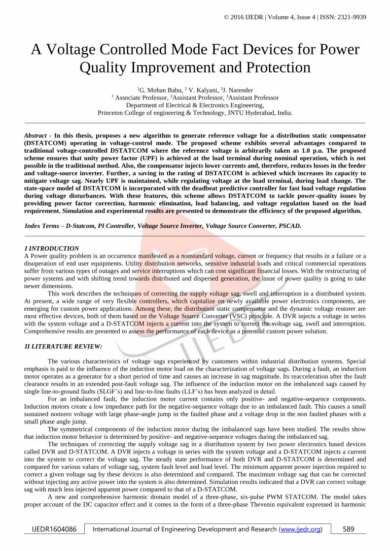
IV SOFTWARE:
SIMULINK CIRCUIT:
The control scheme is implemented using PSCAD software. Simulation parameters are given in three conditions, namely,
nominal operation, operation during sag, and operation during load change are compared between the traditional and proposed
method. In the traditional method, the reference voltage is 1.0p.u. Whereas in the proposed method is used to find the reference
voltage.
4.1. CONVENTIONAL CIRCUIT DIAGRAM:
Figure: Conventional circuit diagram
4.2. DURING NOMINAL OPERATION:

© 2016 IJEDR | Volume 4, Issue 4 | ISSN: 2321-9939
IJEDR1604086 International Journal of Engineering Development and Research (www.ijedr.org) 591
Figure: Terminal voltages and source currents in phase a, b and c
Figure: DC bus voltage regulated at nominal voltage of 1300 V

© 2016 IJEDR | Volume 4, Issue 4 | ISSN: 2321-9939
IJEDR1604086 International Journal of Engineering Development and Research (www.ijedr.org) 592
Figure: The load angle settled around
Figure: Reactive Power at PCC ( )
Figure: Compensator Reactive Power ( )
Figure: Load Reactive Power ( )
© 2016 IJEDR | Volume 4, Issue 4 | ISSN: 2321-9939
IJEDR1604086 International Journal of Engineering Development and Research (www.ijedr.org) 593
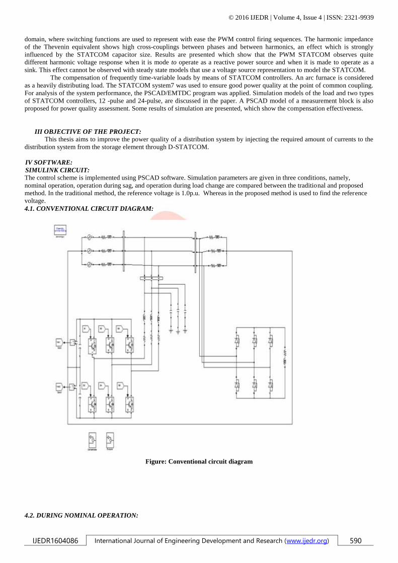
Figure: Source RMS current in phase-a
Figure: Compensator RMS current in phase-a
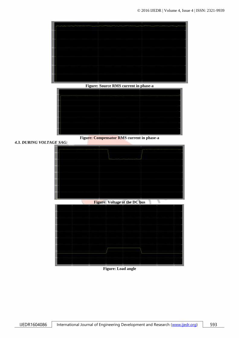
4.3. DURING VOLTAGE SAG:
Figure: Voltage at the DC bus
Figure: Load angle
© 2016 IJEDR | Volume 4, Issue 4 | ISSN: 2321-9939
IJEDR1604086 International Journal of Engineering Development and Research (www.ijedr.org) 594
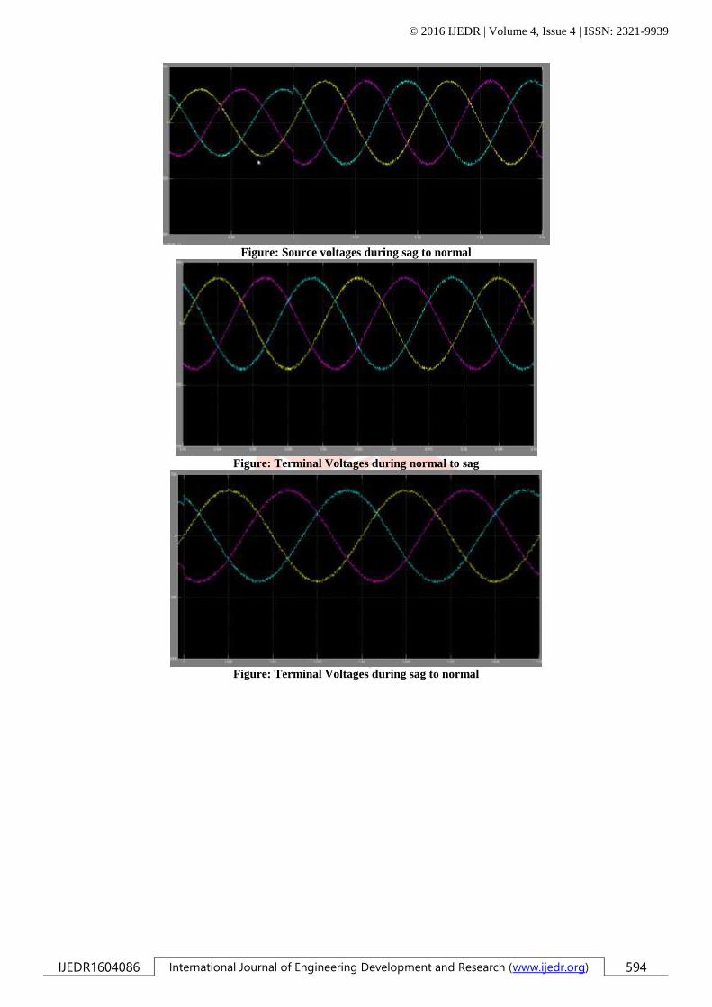
Figure: Source voltages during sag to normal
Figure: Terminal Voltages during normal to sag
Figure: Terminal Voltages during sag to normal

© 2016 IJEDR | Volume 4, Issue 4 | ISSN: 2321-9939
IJEDR1604086 International Journal of Engineering Development and Research (www.ijedr.org) 595
Figure: Compensator RMS current
4.4. DURING LOAD CHANGE:
Figure: Terminal Voltage in phase-a during Load Change
Figure: Source current in phase-a during Load Change
4.5. PROPOSED CIRCUIT DIAGRAM:

© 2016 IJEDR | Volume 4, Issue 4 | ISSN: 2321-9939
IJEDR1604086 International Journal of Engineering Development and Research (www.ijedr.org) 596
Figure: Proposed circuit diagram
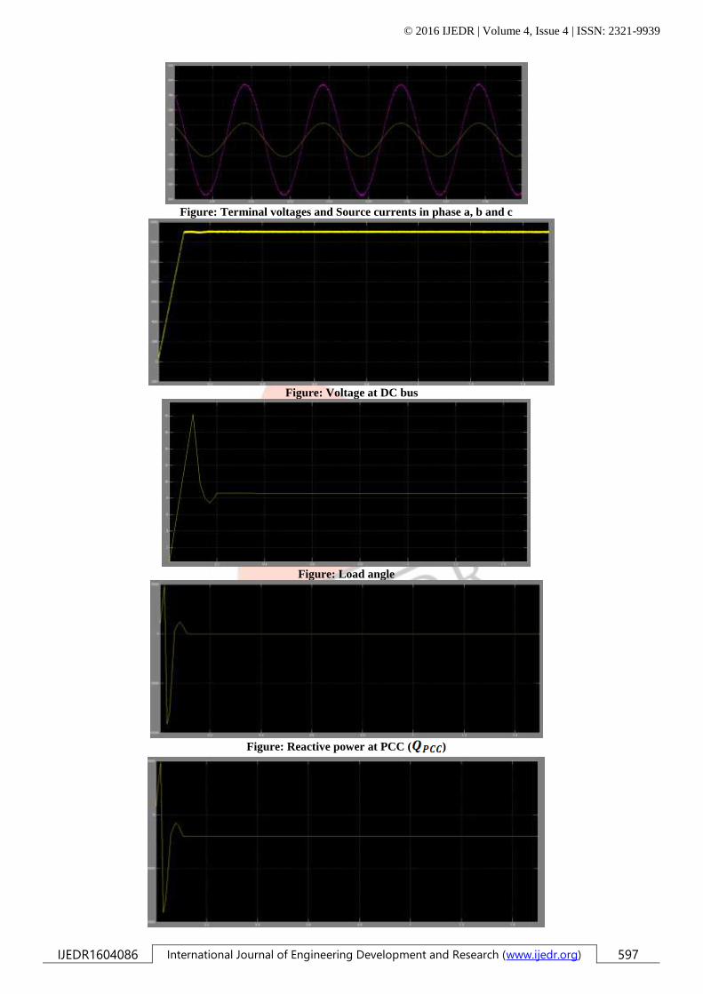
4.6. DURING NOMINAL OPERATION:
© 2016 IJEDR | Volume 4, Issue 4 | ISSN: 2321-9939
IJEDR1604086 International Journal of Engineering Development and Research (www.ijedr.org) 597
Figure: Terminal voltages and Source currents in phase a, b and c
Figure: Voltage at DC bus
Figure: Load angle
Figure: Reactive power at PCC ( )

© 2016 IJEDR | Volume 4, Issue 4 | ISSN: 2321-9939
IJEDR1604086 International Journal of Engineering Development and Research (www.ijedr.org) 598
Figure: Compensator Reactive Power ( )
Figure: Load Reactive Power ( )
Figure: Source RMS current in phase-a
Figure: Compensator RMS current in phase-a
In the traditional method, DSTATCOM maintains a load terminal voltage at 1.0 p.u. For this, it needs to compensate for
the entire feeder drop. Hence, at the stead state, the compensator supplies reactive power to the source to overcome this drop.
However, in the proposed scheme, the compensator does not compensate for the feeder drop in the steady-state condition.
Hence, a less rating of VSI is utilized in the steady state. This savings in rating is utilized to mitigate deep sag, and DSTATCOM
capacity to mitigate deep sag increases.
4.7. DURING VOLTAGE SAG:
Figure: Voltage at the DC bus

© 2016 IJEDR | Volume 4, Issue 4 | ISSN: 2321-9939
IJEDR1604086 International Journal of Engineering Development and Research (www.ijedr.org) 599
Figure: Compensator RMS current
Figure: Source Voltages during Voltage Sag
Figure: Terminal Voltages
4.8. DURING LOAD CHANGE:
Figure: Terminal Voltage during Load Change
Figure: Source Current during Load Change
The traditional method gives less power factor as the compensator will supply more reactive current to maintain the
reference voltage. In proposed method, a load change will result in small deviation in terminal voltage from its reference voltage.
Compensator just needs to supply extra reactive current to overcome this small extra feeder drop, hence, nearly UPF is
maintained while regulating the terminal voltage at its reference voltage.
© 2016 IJEDR | Volume 4, Issue 4 | ISSN: 2321-9939
IJEDR1604086 International Journal of Engineering Development and Research (www.ijedr.org) 600
V. CONCLUSION: Nonlinear loads produce harmonic currents that can propagate to other locations in the power system and eventually
return back to the source. Therefore, harmonic current propagation produces harmonic voltages throughout the power
systems.
The performance of the proposed scheme is compared with the traditional voltage-controlled DSTATCOM. The proposed
method provides the following advantages:
1. At nominal load, the compensator injects reactive and harmonic components of load currents, resulting in UPF.
2. Nearly UPF is maintained for a load change.
3. Fast voltage regulation has been achieved during voltage disturbances.
4. Losses in the VSI and feeder are reduced considerably, and have higher sag supporting capability with the same VSI
rating compared to the traditional scheme.
The simulation and experimental results show that the proposed scheme provides DSTATCOM, a capability to improve several
PQ problems.
VI. REFERENCES: [1] M. Bollen, Understanding Power Quality Problems. Piscataway, NJ, USA: IEEE, 2000, ch. 1, pp. 1–35.
[2] H. Fujita and H. Akagi, “Voltage-regulation performance of a shunt activefilter intended for installation on a power
distribution system,” IEEE Trans. Power Electron., vol. 22, no. 3, pp. 1046–1053, May 2007.
[3] A. Ghosh and G. Ledwich, “Load compensating DSTATCOM in weak ac systems,”IEEE Trans. Power Del., vol. 18, no. 4,
pp. 1302–1309, Oct. 2003.
[4] A. Elnady and M. Salama, “Unified approach for mitigating voltage sag and voltageflicker using the DSTATCOM,” IEEE
Trans. Power Del., vol. 20, no. 2, pt. 1, pp. 992–1000, Apr. 2005.
[5] S.Rahmani,A.Hamadi,andK.Al-Haddad,“ALyapunov-functionbased control for three-phase shunt hybrid activefilter,”IEEE
Trans. Ind. Electron., vol. 59, no. 3, pp. 1418–1429, Mar. 2012.
[6] M. K. Mishra and K. Karthikeyan, “A fast-acting dc-link voltage controller for three-phase DSTATCOM to compensate ac
and dc loads,” IEEE Trans. Power Del., vol. 24, no. 4, pp. 2291–2299, Oct. 2009.
[7] M. K. Mishra, A. Ghosh, A. Joshi, and H. M. Suryawanshi, “A novel method of load compensation under unbalanced and
distorted voltages,”IEEE Trans. Power Del., vol. 22, no. 1, pp. 288–295, Jan. 2007.
[8]M.K.Mishra,A.Ghosh,andA.Joshi,“OperationofaDSTATCOM in voltage control mode,”IEEE Trans. Power
Del.,vol.18,no.1,pp. 258–264, Jan. 2003.
[9] A. Jain, K. Joshi, A. Behal, and N. Mohan, “Voltage regulation with STATCOMs: Modeling, control and results,”IEEE
Trans. Power Del., vol. 21, no. 2, pp. 726–735, Apr. 2006.
[10] R. Gupta, A. Ghosh, and A. Joshi, “Switching characterization of cascaded multilevel-inverter-controlled systems,”IEEE
Trans. Ind. Electron., vol. 55, no. 3, pp. 1047–1058, Mar. 2008.


