MINISTRY OF EDUCATION AND TRAINING
DA NANG UNIVERSITY
VU PHAN HUAN
A STUDY OF INTELLIGENT METHODS
FOR FAULT CLASSIFICATION AND
FAULT LOCATION ON THE TRANSMISSION LINE
SPECIALIZATION: POWER SYSTEM & NETWORK
CODE: 62.52.50.05
PHD. THESIS IN BRIEF
Da Nang - 2014
This thesis has been finished at:
Danang University of Technology, Da Nang University
Supervisor: Assoc, Prof. PhD. Le Kim Hung
Examiner 1: Assoc, Prof. PhD. Phan Thi Thanh Binh
Examiner 2: Prof. Dr. Tran Đinh Long
Examiner 3: Assoc, Prof. PhD. Nguyen Hong Anh
The PhD.Thesis will be defended at the Thesis Assessment
Committee at Da Nang University Level at Room No:
.............................................................................................................
.............................................................................................................
.............................................................................................................
At date 07 month 06 year 2014
The thesis is available at:
1. The National Library.
2. The Information Resources Center, University of Danang.

1
INTRODUCTION
1. THE REASON FOR CHOOSING THE THESIS
Fault location methods on EVN’s transmission line, which is
based on the experimental operation and relay protection (using
measurement data at one overhead line). Therefore, it meets many
difficulties in locating faults, increasing time electric losts,
economics damages. Thus, the thesis “a study of intelligent methods
for fault classification and fault location on the tranmisstion line”
has scientific meaning and application in managing electrical
operations.
2. THE CONTENT AND PURPOSES OF THE RESEARCH
The content and purposes of the research such as:
- Systematizing methods, the researches published in the fault
classification and location area on the grid’s power transmission.
- Researching effects of main factors on the performance and
calculating distance to fault of relay protection.
- Assessing fault location methods of relay manufacturers, which
are for the diagram of transmission lines using current, voltage
data measurement at one, two or three ended of the transmission
line.
- The research uses intelligent methods in order to classify and
locate transmission line’s faults.
3. RESEARCH METHODS
The thesis combines two methods: theory research and
experimental research.
4. THE OBJECTIVE AND SCOPE OF RESEARCH

2
Fault location methods of numerical relay protection from
manufacturers like ABB, SIEMENS, AREVA, SEL.Inc, TOSHIBA,
etc. applied popularly on the high-voltage transmission grid, which
has voltage level from 110 kV to 220 kV. The research uses
intelligent methods like Fuzzy, Wavelet, ANN, and ANFIS that is for
classifying and locating faults.
5. THE MEANING OF SCIENCE AND PRACTICE OF THE THESIS
5.1 The meaning of science:
During the process, analyzing and assessing the fault location
methods of numerical relay are the foundation to develop methods of
solving fault location’s problems with higher level of accuracy.
The thesis concreted methods of analysis positive, negative and
zero component sequence of the relationship angle and magnitude
ratio between the currents, which are applied on building Fuzzy laws
for fault classification. Base on that, testing for transmission line’s
diagram 220kV A Vuong – Hoakhanh.
With this model 220kV, the author builds classification methods
base on Discrete Wave Transform (DWT) analysis of transient
signals (Ia, Ib, Ic and Io), which combines with algorithm comparing
between current value and fault threshold levels.
Besides, the author researches fault classification using ANN
(automatic determining an optimal number of hidden layer neuron) or
ANFIS (with 4 inputs and 1 output) for 10 kinds of faults (AN, BN,
CN, AB, BC, AC, ABG, BCN, ACN, ABN, ABC).
In addition, the fault from the previous year and updated statistics
on Power Transmission Company and Grid Company, which is the
foundation to test and expand applications of ANN, ANFIS
calculating the similar future fault location in the power system.
3
5.2 The practice:
a) Designing and managing electrical consultation processes: The
thesis contributes on quick solving a big amount of work, which is in
fault classification and location at the request of the Power Sector.
Besides, the thesis supplies the knowledge supporting for operation,
increasing the effectiveness of relay’s utilization.
b) Orienting Power sector’s investment: The thesis’s result for the
fault location techniques (in 110 kV and 220 kV transmission line) is
the foundation towards building the fault solving process for various
types of transmission line in Viet Nam.
6. COMPOSITION OF THE THESIS
Outside of the Introduction, appendix, this thesis consists of five
chapters.
CHAPTER 1
OVERVIEW STUDY ON FAULT CLASSIFICATION
AND LOCATION
1.1 INTRODUCTION
1.2 OVERVIEW OF THE RESEARCH
1.2.1. The technique based on power management
1.2.2 The technique based on fundamental frequency signals,
mainly on impedance measurement.
1.2.3 The technique based on high frequency components of
signals generated by faults.
1.2.4 The technique based on intelligent systems
1.2.5 The technique based on hybrid method
1.3 CONCLUSION
Chapter 1 generally introduced about fault location and
classification methods on the transmission line. In which, intelligent

4
methods utilize on classifying and locating faults with high accuracy,
which continuous develop by scientists on the world. In Vietnam,
there are some fault detecting researches, but it is still new, especially
intelligent methods applied on this area is rare. Therefore, the
necessary is continuous developing these researches to find solutions
of accurate and quick fault detection on the transmission line;
suitable with conditions of real transmission lines; overcome factors
affecting on outputs. It is the thesis’s content.
CHAPTER 2
THE EFFECT OF MAIN FACTORS ON THE
PERFORMANCE AND IDENTIFY OF RELAY
PROTECTION
2.1 INTRODUCTION
2.2 THE EFFECT OF HARMONIC ON RELAY PROTECTION
IN POWER SYSTEM
2.2.1 Harmonic on power system
Harmonics has always existed in electrical power systems. It
induced by these nonlinear loads are a potential risk.
Figure 2.1a: numerical values of a set of harmonics at transformer T1
in substation 110kV Dong Ha.
Figure 2.1b: Connection of
Analyzer to 3 phase distribution system
2.2.2 Effect of harmonic on protection relay
2.2.3 Revew and evaluation
5
The testing effect of harmonic on electro-mechanical, static and
numerical protection relay were performed by Fluke 434 (figure 2.1)
and the total harmonic distortion of the nonlinear-load current
(THDi) are adjusted by CMC 256. In this study, electromechanical
relay (EIOCR, ITOCR) designs for sinusoidal current, operates faulty
in non-sinusoidal current. How ever, the static relay and numerical
relay have measurement function and harmonic restraint function that
helps the relay can perform right protection function in the distortion
of the current.
2.3 THE EFFECT OF FAULT RESISTANCE ON THE
PERFORMANCE OF DISTANCE RELAY PROTECTION
2.3.1 Fault resistance of a transmission line that fed from one end
2.3.2 Fault resistance of a transmission line that fed from double end
2.3.3 Overcome limitations of fault resistance on the performance
of relay’s characteristic
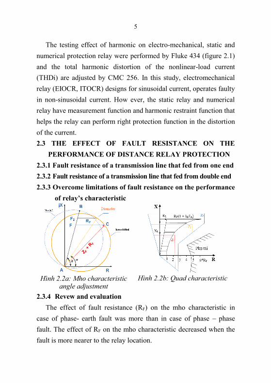
Hình 2.2a: Mho characteristic
angle adjustment
Hình 2.2b: Quad characteristic
2.3.4 Revew and evaluation
The effect of fault resistance (RF) on the mho characteristic in
case of phase- earth fault was more than in case of phase – phase
fault. The effect of RF on the mho characteristic decreased when the
fault is more nearer to the relay location.
6
To overcome the under reach due to the effects of resistance faults
(may make relays response slowly), relays use some typical methods
like moving angular of mho characteristic impedance or using
quadrilateral characteristic style (Figure 2.2).
2.4 THE EFFECT OF CT, VT ERROR ON THE MEASUREMENT
OF RELAY PROTECTION
2.4.1 CT, VT error
2.4.2 Improving accuracy of CT, VT
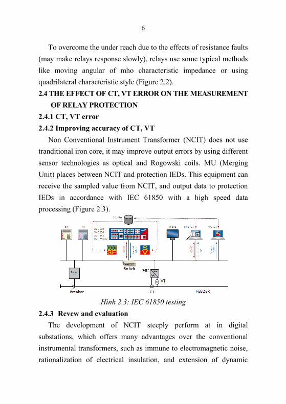
Non Conventional Instrument Transformer (NCIT) does not use
tranditional iron core, it may improve output errors by using different
sensor technologies as optical and Rogowski coils. MU (Merging
Unit) places between NCIT and protection IEDs. This equipment can
receive the sampled value from NCIT, and output data to protection
IEDs in accordance with IEC 61850 with a high speed data
processing (Figure 2.3).
Hình 2.3: IEC 61850 testing
2.4.3 Revew and evaluation
The development of NCIT steeply perform at in digital
substations, which offers many advantages over the conventional
instrumental transformers, such as immune to electromagnetic noise,
rationalization of electrical insulation, and extension of dynamic
7
ranges and frequency bands of the measured signals, therefore to
achieve higher performance, higher compactness and higher
reliability of instrument transformers. So that NCIT is recommended
to applying in combination with IED such as digital relays, digital
measurement system or digital device measurement of electric
quality, which intend to collect current data, voltage accurately for
different purposes.
2.5 THE EFFECT OF LINE PARAMETER ON THE
PERFORMANCE OF RELAY PROTECTION
2.5.1 Line impedances
2.5.2 Calculating impedances and the k-factor
2.5.2.1 Line parameter measurement with electronic machines
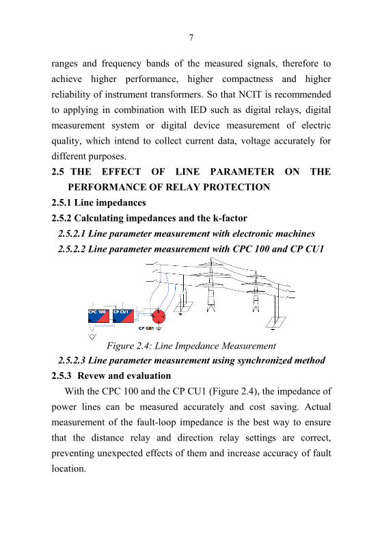
2.5.2.2 Line parameter measurement with CPC 100 and CP CU1
Figure 2.4: Line Impedance Measurement
2.5.2.3 Line parameter measurement using synchronized method
2.5.3 Revew and evaluation
With the CPC 100 and the CP CU1 (Figure 2.4), the impedance of
power lines can be measured accurately and cost saving. Actual
measurement of the fault-loop impedance is the best way to ensure
that the distance relay and direction relay settings are correct,
preventing unexpected effects of them and increase accuracy of fault
location.
8
2.6 CONCLUSION
Based on the analysis of the factors of harmonic, fault resistance,
CT, VT error and line parametter to show that the demands with relay
protection is beliable, selective, and quick removal fault feasible only
if current and voltage value collected accurately, the relay’s functions
and parameters set correctly. The consideration of these factors
contributes to the collection of believe information, meet the
accuracy of fault detection algorithms.
CHAPTER 3
FAULT LOCATION ALGORITHMS ANALYSIS FOR NUMERICAL RELAY
3.1 INTRODUCTION
3.2 ANALYSES OF EVENT RECORD FUNCTION OF
NUMERICAL RELAY WITH THE USE OF SOFTWARE
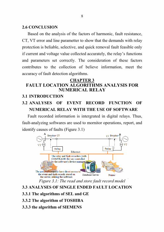
Fault recorded information is intergrated in digital relays. Thus,
fault-analyzing softwares are used to mornitor operations, report, and
identify causes of faults (Figure 3.1)
Figure 3.1: The read and store fault record model
3.3 ANALYSES OF SINGLE ENDED FAULT LOCATION
3.3.1 The algorithms of SEL and GE
3.3.2 The algorithm of TOSHIBA
3.3.3 the algorithm of SIEMENS
9
3.3.4 The algorithm of ABB
3.3.5 The algorithm of AREVA
3.3.6 Review and evaluation
The singled end fault location methods using current, voltage data
at one terminal, which have advantages of being suitable with
conditions of networks and technology of protection in countries.
However, the formula is build on the homogenous power system, so
the method has disadvantages of reducing level of accuracy: the mix
influence of the load current and fault resistance, the value may be
high at ground faults; the accuracy of line’s parameters set on relays;
measurement errors…
3.4 ANALYSES OF TWO ENDED FAULT LOCATION
3.4.1 The algorithm of TOSHIBA
3.4.2 The algorithm of SEL
3.4.3 Revew and evaluation
The fault location method using two terminal line, which uses
possitive and negative sequence quantities. It can improve upon the
accuracy of single ended methods. The limitation of this method is
expensive devices, because the signal needs to collected
synchronously, using a big mount of send and receive data (if there is
GPS system). Therefore, it has not used popularly in Vietnam.
3.5 FAULT LOCATION ALGORITHMS ANALYSIS FOR THREE
TERMINAL TRANSMISSION LINES
3.5.1 The algorithm using unsynchronized sampling of SEL
3.5.2 The algorithm using synchronized sampling of TOSHIBA
3.5.3 The algorithm using expanded Clarke transformation of GE
3.5.4 Revew and evaluation

10
Base on the result of analyzing the fault location method of SEL,
TOSHIBA, and GE relays, which is used for the three terminal
transmission line. It shows that the result of distance to the fault point
calculate with real time is not affected by fators, including mutual
coupling lines. In which, accurate of SEL is the biggest error, and
TOSHIBA is smallest error. In another way, these methods always
remain errors, so it needs deeper researches to improve calculations’
accuracy.
3.6 CONCLUSION
Fault location methods using data measurement at two or three
terminal line, which are only performed under conditions of
compeleting information management in order to serve measuring the
data at the center control.
Fault location methods using data measurement at one terminal
line, which are applied popularly on substation in Vietnam. However,
they almost concentrate on solving faults in each local line. It has
errors bigger than other method, so the value of fault location is
different from the actual position. The next chapter presents fault
classification and location methods built on intelligent system, which
use current, voltage data on relays and actual fault position in order to
solve problem effectively.
CHAPTER 4
INTELLIGENT TECHNIQUES FOR TRANSMISSION
LINE FAULT CLASSIFICATION
4.1 INTRODUCTION
4.2 CLASSIFICATION OF FAULTS ON POWER TRANMISSION
LINES USING FUZZY LOGIC
4.2.1 Fuzzy logic algorithm for fault classification

11
Step 1: Fuzzify inputs
Step 2: Apply fuzzy operator
Step 3: Apply implication method
Step 4: Aggregate and defuzzify of all outputs
Figure 4.1a: Input Membership
Function α
Figure 4.1b: Input Membership
Function β
Figure 4.1c: Input Membership
Function R21
Figure 4.1d: Input Membership
Function R02
Figure 4.1e: Output Membership
Function fault types
Figure 4.1f: Rule Base
4.2.2 Simulation and results
The single-line diagram of the simulated system is a 220kV
Transmission Line A Vuong – Hoa Khanh. The results obtained from
the analysis are clearly presented in appendix 4.1.
12
4.2.3 Revew and evaluation
In order to distinguish every fault type instead of using current
phase quantities, the thesis only uses 4 coefficients α, β, R21, R02 at
one end of transmission line. The Fuzzy logic supply results rapidly
and effectively.
4.3 FAULT CLASSIFICATION OF POWER TRANMISSION
LINES USING WAVELET TRANSFORM
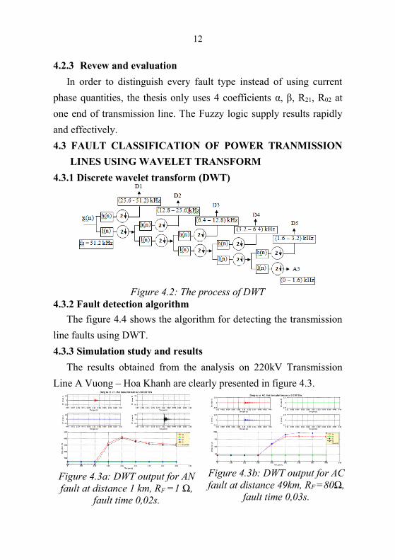
4.3.1 Discrete wavelet transform (DWT)
Figure 4.2: The process of DWT
4.3.2 Fault detection algorithm
The figure 4.4 shows the algorithm for detecting the transmission
line faults using DWT.
4.3.3 Simulation study and results
The results obtained from the analysis on 220kV Transmission
Line A Vuong – Hoa Khanh are clearly presented in figure 4.3.
Figure 4.3a: DWT output for AN
fault at distance 1 km, RF =1 Ω,
fault time 0,02s.
Figure 4.3b: DWT output for AC
fault at distance 49km, RF =80Ω,
fault time 0,03s.

13
Figure 4.3c: DWT output for ACN
fault at distance 35km, RF =200Ω,
fault time 0,04s.
Figure 4.3d: DWT output for ABC
fault at distance 45km, RF =150Ω,
fault time 0,05s.
4.3.4 Revew and evaluation
The thesis researches fault
detection and classification of
short-circuit by using discrete
wavelet transform. Each case
corresponds to the problem on
the transmission grid, three -
phase current signal Ia, Ib, Ic,
and Io, which is used to analyze
db5. In which, detail signals in
anslyzing level 1 were found,
that is the most appropriate to
detect faults (faults time).
Besides, base on the signal’s
differency; comparing current
value for each phase from details
Figure 4.4: Fault detection using
discrete wavelet transform
and appropriate 1 sampling cycle current signal (1024); comparing with
threshold value (ε1), the tow phase current ratio (ε2), the ratio of neutral
current and current phase (ε3), in order to classify faults. The algorithm

14
does not depend on fault time, distance and resistor. The simulate result
points out that the method is very effective in fault classification.
4.4 FAULT CLASSIFICATION IN TRANSMISSION LINES USING
ANN
4.4.1 Steps in designing an ANN
for fault classification
Eight steps in designing ANN
forecasting model:
Step 1: Variable selection
Step 2: Data collection
Step 3: Data preprocessing
Step 4: Training, testing sets
Step 5: Neural network paradigms
Step 6: Evaluation criteria
Step 7: ANN training
Step 8: Implementation ANN Figure 4.5: Designing an ANN
for fault classification
Figure 4.6: Architectures of ANN for fault classification using 4
neuron input, 5 hiden neuron and 4 neuron output
15
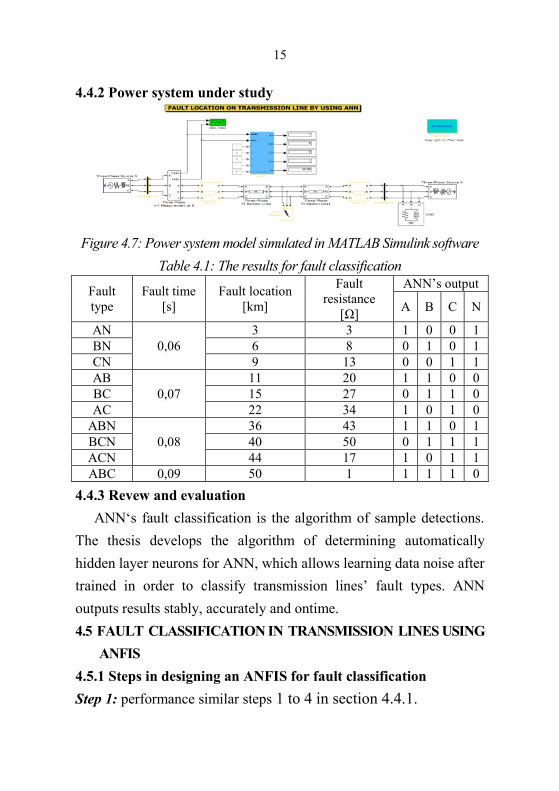
4.4.2 Power system under study
Figure 4.7: Power system model simulated in MATLAB Simulink software
Table 4.1: The results for fault classification
Fault
type
Fault time
[s]
Fault location
[km]
Fault
resistance
[Ω]
ANN’s output
A B C N
AN
0,06
3 3 1 0 0 1
BN 6 8 0 1 0 1
CN 9 13 0 0 1 1
AB
0,07
11 20 1 1 0 0
BC 15 27 0 1 1 0
AC 22 34 1 0 1 0
ABN
0,08
36 43 1 1 0 1
BCN 40 50 0 1 1 1
ACN 44 17 1 0 1 1
ABC 0,09 50 1 1 1 1 0
4.4.3 Revew and evaluation
ANN‘s fault classification is the algorithm of sample detections.
The thesis develops the algorithm of determining automatically
hidden layer neurons for ANN, which allows learning data noise after
trained in order to classify transmission lines’ fault types. ANN
outputs results stably, accurately and ontime.
4.5 FAULT CLASSIFICATION IN TRANSMISSION LINES USING
ANFIS
4.5.1 Steps in designing an ANFIS for fault classification
Step 1: performance similar steps 1 to 4 in section 4.4.1.

16
Step 2: design ANFIS.
Step 3: train ANFIS.
Figure 4.8a. Structure of ANFIS
for fault classification
Figure 4.8b. Membership
function of input variables for
fault classification
4.5.2 Power system under study
Power system under study is similary section 4.4.2.
Table 4.2: The results for fault classification
Fault type Fault time [s]
Fault
locaton
[km]
Fault
resistance
[Ω]
ANFIS’s
output
AN
0,06
3 3 1,0
BN 6 8 2,0
CN 9 13 3,0
AB
0,07
11 20 4,0
BC 15 27 5,0
AC 22 34 6,0
ABN
0,08
36 43 7,0
BCN 40 50 7,99
ACN 44 17 8,99
ABC 0,09 50 1 10
4.5.3 Revew and evaluation
The thesis develops the ANFIS network structure using 4 inputs, 1
output in fault classification. The result shows that ANFIS is suitable with
transmission lines, meets time demands and errors for each application.
17
4.6 CONCLUSTION
This chapter was designed to evaluate the applicability of intelligent
techniques including FL, WT, ANN and ANFIS for fault classification
estimation in overhead transmission line. It would be interesting to
compare these techniques with each others. According to the results,
the results produced by WT show a good level of accuracy.
CHAPTER 5
FAULT LOCATION ON OVERHEAD TRANSMISSION LINE USING ANN, ANFIS
5.1 INTRODUCTION
5.2 FAULT LOCATION ON OVERHEAD TRANSMISSION
LINE USING ANN
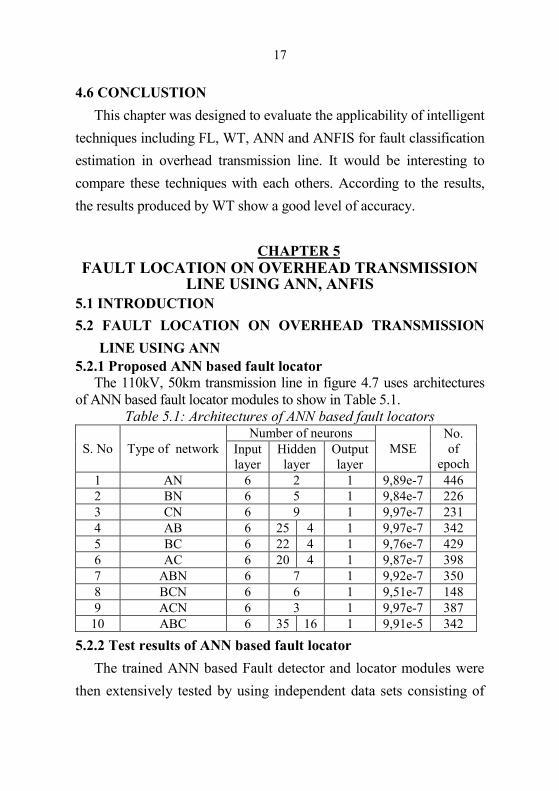
5.2.1 Proposed ANN based fault locator
The 110kV, 50km transmission line in figure 4.7 uses architectures
of ANN based fault locator modules to show in Table 5.1.
Table 5.1: Architectures of ANN based fault locators
S. No Type of network
Number of neurons
MSE
No.
of
epoch Input
layer
Hidden
layer
Output
layer
1 AN 6 2 1 9,89e-7 446
2 BN 6 5 1 9,84e-7 226
3 CN 6 9 1 9,97e-7 231
4 AB 6 25 4 1 9,97e-7 342
5 BC 6 22 4 1 9,76e-7 429
6 AC 6 20 4 1 9,87e-7 398
7 ABN 6 7 1 9,92e-7 350
8 BCN 6 6 1 9,51e-7 148
9 ACN 6 3 1 9,97e-7 387
10 ABC 6 35 16 1 9,91e-5 342
5.2.2 Test results of ANN based fault locator
The trained ANN based Fault detector and locator modules were
then extensively tested by using independent data sets consisting of
18
fault scenarios never used previously in training. Fault type, fault
location and fault time were changed to investigate the effects of
these factors on the performance of the proposed algorithm. The
results obtained are explained in more detail in appendix 5.1.
5.2.3 Revew and evaluation
The fault location technique basing on artificial neuron network is
trained to detect faults and use 10 different ANN, which has errors in
the range of 0,04% to 3,044%. Thus, all test results are correct with
reasonable accuracy. However, each ANN needs training time from
40 to 50 minutes in order to find the optimal network.
5.3 FAULT LOCATION ON OVERHEAD TRANSMISSION
LINE USING ANFIS
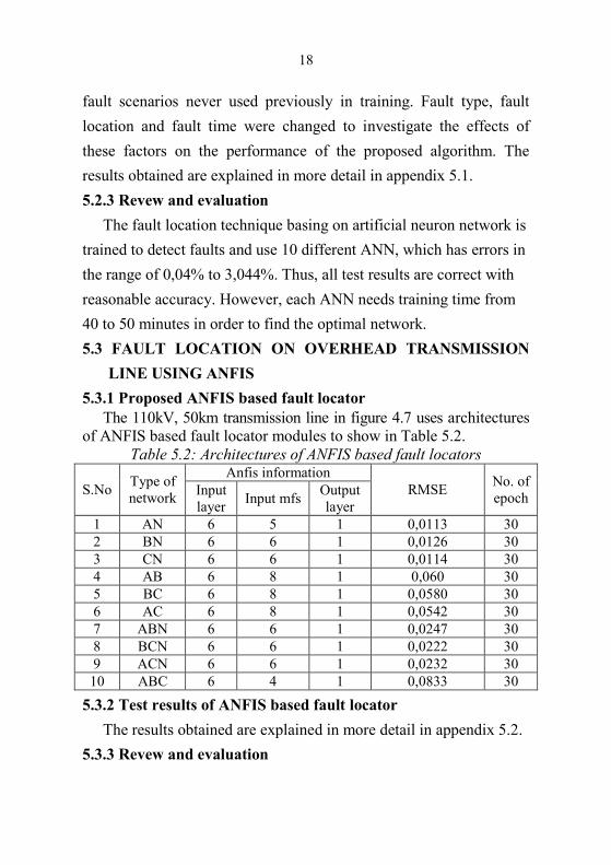
5.3.1 Proposed ANFIS based fault locator
The 110kV, 50km transmission line in figure 4.7 uses architectures
of ANFIS based fault locator modules to show in Table 5.2.
Table 5.2: Architectures of ANFIS based fault locators
S.No Type of
network
Anfis information
RMSE No. of
epoch Input
layer Input mfs
Output
layer
1 AN 6 5 1 0,0113 30
2 BN 6 6 1 0,0126 30
3 CN 6 6 1 0,0114 30
4 AB 6 8 1 0,060 30
5 BC 6 8 1 0,0580 30
6 AC 6 8 1 0,0542 30
7 ABN 6 6 1 0,0247 30
8 BCN 6 6 1 0,0222 30
9 ACN 6 6 1 0,0232 30
10 ABC 6 4 1 0,0833 30
5.3.2 Test results of ANFIS based fault locator
The results obtained are explained in more detail in appendix 5.2.
5.3.3 Revew and evaluation

19
To compare with ANN, ANFIS is a better choice as: quick training
time; output errors in the range of 0,042 ÷ 3,062%. Thus, the next
thesis’s object is actual testing ANFIS design and application in order
to locate fault on the transmission line.
5.4 FAULT LOCATION ASSESSMENT
Figure 5.1: Application of ANFIS approach to fault classification
and location on transmission line
5.4.1 The 110kV transmission line Dak Mil – Dak Nong
5.4.1.1 Verified model
Figure 5.2: The 110kV transmission line Dak Mil – Dak Nong
5.4.1.2 Generation a suitable training data
Matlab Simulink program is developed for generating training
patterns with various fault type, fault resistance, fault location.
Table 5.3: Parameter settings for generating training patterns
Case No Parameters Set value
1 Fault type AN, BN, CN, AB, BC, AC, ABN, BCN,
ACN, ABC
2 Fault location [km] 1, 5, 10, 15, 20,25, 30, 35, 40, 45, 50, 55
3 Loading [MVA] 10, 30, 50, 70
4 Fault resistance RF [Ω] 1, 3, 5, 7, 10
5 Time fault [s] 0.07, 0.075
20
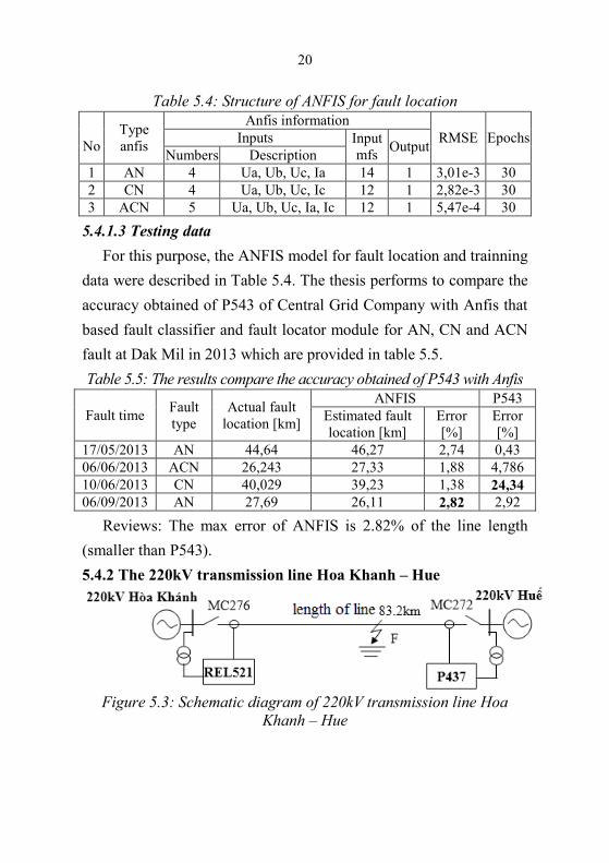
Table 5.4: Structure of ANFIS for fault location
No
Type
anfis
Anfis information
RMSE Epochs Inputs Input
mfs Output
Numbers Description
1 AN 4 Ua, Ub, Uc, Ia 14 1 3,01e-3 30
2 CN 4 Ua, Ub, Uc, Ic 12 1 2,82e-3 30
3 ACN 5 Ua, Ub, Uc, Ia, Ic 12 1 5,47e-4 30
5.4.1.3 Testing data
For this purpose, the ANFIS model for fault location and trainning
data were described in Table 5.4. The thesis performs to compare the
accuracy obtained of P543 of Central Grid Company with Anfis that
based fault classifier and fault locator module for AN, CN and ACN
fault at Dak Mil in 2013 which are provided in table 5.5.
Table 5.5: The results compare the accuracy obtained of P543 with Anfis
Fault time Fault
type
Actual fault
location [km]
ANFIS P543
Estimated fault
location [km]
Error
[%]
Error
[%]
17/05/2013 AN 44,64 46,27 2,74 0,43
06/06/2013 ACN 26,243 27,33 1,88 4,786
10/06/2013 CN 40,029 39,23 1,38 24,34
06/09/2013 AN 27,69 26,11 2,82 2,92
Reviews: The max error of ANFIS is 2.82% of the line length
(smaller than P543).
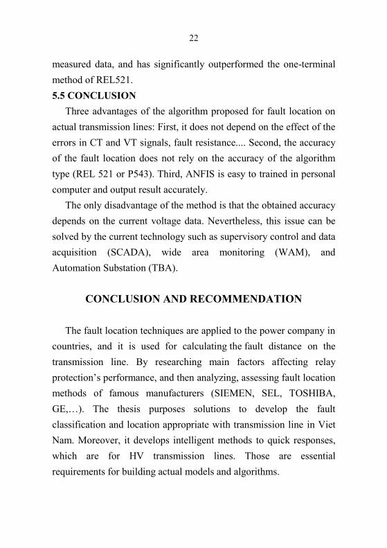
5.4.2 The 220kV transmission line Hoa Khanh – Hue
Figure 5.3: Schematic diagram of 220kV transmission line Hoa
Khanh – Hue

21
Table 5.6: Parameter settings for generating training patterns. Case No Parameters Set value
1 Fault type AN, BN, CN, AB, BC, AC, ABN,
BCN, ACN, ABC
2 Fault location [km] 1, 10, 20,30, 40, 50, 60, 70, 80
3 Time fault [s] 0.075, 0.08
4 Fault resistance RF [Ω] 1, 5, 10, 20, 30
5 Loading [MVA] 1, 50, 100, 200
Table 5.7: Structure of Anfis for fault location
No
Type
anfis
Anfis information
RMSE Epochs Inputs Input mfs Đâu ra
Numbers Description
1 AN 4 Ua, Ub, Uc, Ia 14 1 2,41e-3 20
2 BN 4 Ua, Ub, Uc, Ib 14 1 1,16e-3 20
3 ABN 5 Ua, Ub, Uc, Ia, Ib 12 1 4,22e-3 20
4 BCN 5 Ua, Ub, Uc, Ib, Ic 12 1 3,12e-4 20
In this case, the ANFIS model for fault location and trainning data
were described in Table 5.7, the thesis performs to compare the
accuracy obtained of REL521 of tranmission line 276 at 220kV Hoa
Khanh Substation with Anfis that are provided in table 5.8.
Table 5.8: Results compare the accuracy obtained of REL521 with ANFIS
Fault time Fault
type
Actual fault
location [km]
ANFIS P543
Estimated fault
location [km]
Error
[%]
Error
[%]
1/6/2009 ABN 29,36 29,46 0,36 2,24
16/10/2010 BN 27,4 22,95 1,38 3,97
2/8/2010 BN 35,9 36,08 0,03 0,12
12/8/2010 ABN 63,1 61,3 2,16 4,93
17/5/2011 BCN 25,4 27,55 1,38 1,20
20/5/2011 AN 81,8 83,22 0,02 1,68
19/8/2012 ABN 26,4 24,80 1,81 1,44
Reviews: Output of ANFIS for ABN fault is the highest error
2,16% of the line length. It can be clearly seen from the test results
that the proposed method, which requires the same amount of
22
measured data, and has significantly outperformed the one-terminal
method of REL521.
5.5 CONCLUSION
Three advantages of the algorithm proposed for fault location on
actual transmission lines: First, it does not depend on the effect of the
errors in CT and VT signals, fault resistance.... Second, the accuracy
of the fault location does not rely on the accuracy of the algorithm
type (REL 521 or P543). Third, ANFIS is easy to trained in personal
computer and output result accurately.
The only disadvantage of the method is that the obtained accuracy
depends on the current voltage data. Nevertheless, this issue can be
solved by the current technology such as supervisory control and data
acquisition (SCADA), wide area monitoring (WAM), and
Automation Substation (TBA).
CONCLUSION AND RECOMMENDATION
The fault location techniques are applied to the power company in
countries, and it is used for calculating the fault distance on the
transmission line. By researching main factors affecting relay
protection’s performance, and then analyzing, assessing fault location
methods of famous manufacturers (SIEMEN, SEL, TOSHIBA,
GE,…). The thesis purposes solutions to develop the fault
classification and location appropriate with transmission line in Viet
Nam. Moreover, it develops intelligent methods to quick responses,
which are for HV transmission lines. Those are essential
requirements for building actual models and algorithms.

23
New contributions of the thesis:
- The thesis clearly researches the effectiveness of main factors
such as harmonic, fault resistance, CT, VT error and line
parameters on the performance of relay protection. The research
also proposes to use harmonic restraint function, the phase to
earth distance protection with quadrilateral characteristic, phase to
phase distance protection with mho characteristic, NCIT devices,
the CPC 100 + CP CU1 measure line impedances and k-factors on
overhead lines that help the relay can perform correctly protection
function and improve the accuracy in the fault location.
- This thesis analyzes fault location algorithms based on different
relays for overhead transmission line that acquired by the
numerical relay at one terminal, or both the terminals or three-
terminal transmission lines. Based on the literature reviews, the
error of fault location methods were assessed. The research also
propose to choose the most flexible and suitable method for power
system in Viet Nam. It is the double end distance to fault location
method using unsynchronized data measurements employed at
each line end. In addition, this will flexible, suited to the actual
conditions, infrastructure equipment for collection current, voltage
data of the power system Viet Nam at moment and consider to the
development of this in the next years.
- The thesis proposes an approach to the classification of
transmission line fault by using FL, WT, ANN and ANFIS. The
results obtained show that WT is suitable to choose current and
voltage signals for trainning and testing ANN, ANFIS in fault
location rapidly and correctly. This can appropriate with the
collection data plan of EVN in the next time

24
- Based on the above mentioned findings, a procedure for
successful application of fault location based on ANFIS into the
110kV transmission line Dak Mil - Dak Nong and 220kV
transmission line Hoa Khanh – Hue, which was proposed to test in
the practice.
- The thesis is the foundation to calculate fault locations, it
contributes complement to the technique of fault locations
effectively. The results obtained can be used for technical, man
of science, Power Transmission Company, Grid Company to
implement on other HV transmission line in Vietnam’s power
system.
Further research:
Further research is recommended to extend this thesis in the
following concerns:
- The research completes fault location algorithms using the
COMTRADE file of fault data from all IEDs at central control.
- The research completes fault location algorithms on 500kV
transmission line.
- Fault location using wavelet.
Besides, if there is a good condition and with the knowledge
obtained in RLBV for years, it may be registrated subject for
prototyping devices, which is for testing, applicating classification
and location methods.

25
PUBLICATIONS OF THE AUTHOR
[1] Lê Kim Hùng, Vũ Phan Huấn, Xây dựng cẩm nang điện tử và
phần mềm kiểm định Rơle kỹ thuật số. Đề tài khoa học và công
nghệ cấp bộ, Mã số B2010-ĐN01-20. Ngày 08/12/2011.
[2] Le Kim Hung, Nguyen Hoang Viet, Vu Phan Huan, The effect
of Fault resistance on the Performance of distance relay
protection, The International Symposium on Electrical-
Electronics Engineering ISEE, Ho Chi Minh City, Vietnam, 8-9
november 2011. Pages: 238-244.
[3] Le Kim Hung, Nguyen Hoang Viet, Vu Phan Huan, Effect of
harmonic on Protection relay to Power system, The International
Symposium on Electrical-Electronics Engineering ISEE, Ho Chi Minh
City, Vietnam, 8-9 november 2011. Pages: 232-237.
[4] Le Kim Hung, Nguyen Hoang Viet, Vu Phan Huan, A fault
location system for transmission lines using data measurements
from two ends, 2012 International Conference on Green
technology and Subtainable development, Ho Chi Minh City,
Vietnam, 29-30 september 2012. No: 1/2012. Pages: 421-428.
[5] Lê Kim Hùng, Nguyễn Hoàng Việt, Vũ Phan Huấn, “Phân tích
bản ghi sự kiện của rơle kỹ thuật số bằng phân mềm Siemens
Sigra 4”. Tạp chí Khoa học & Công nghệ Đại học Đà Nẵng, Số
51/2012. ISSN: 1859-1531, Trang: 16-25. Năm 2012.
[6] Lê Kim Hùng, Vũ Phan Huấn, Phan Thành Việt, “Nhận dạng
sự cố trên đường dây truyền tải điện bằng hệ mờ”, Tạp chí Khoa
học & Công nghệ Đại học Đà Nẵng, số 9(58)/2012; Q1. Số: 9
(58) / 2012. ISSN: 1859-1531, Trang: 1-7. Năm 2012.
[7] Vu Phan Huan, Le Kim Hung, Nguyen Hoang Viet, “A
26
Studying of Single Ended Fault Locator on Siemens Relay”,
Journal of Electrical and Control Engineering, 2013 Vol.3
No.2. ISSN: 2226-2881, PP.12-17, Pub. Date: 2013- 04-26.
[8] Le Kim Hung, Vu Phan Huan, A Studying Of Single Ended
Fault Locator On SEL Relay, Proceedings of the IETEC’13
Conference, Ho Chi Minh City, Vietnam, 3/6 November 2013.
ISBN: 978-0-646-59658-7.
[9] Lê Kim Hùng, Vũ Phan Huấn, “Phân tích kỹ thuật định vị điểm
sự cố cho đường dây truyền tải có nguồn cung cấp từ 3 phía”,
Tạp chí Khoa học & Công nghệ Đại học Đà Nẵng, Số 69/2013.
ISSN: 1859-1531. Trang: 12-19. Năm 2013.
[10] Le Kim Hung, Nguyen Hoang Viet, Vu Phan Huan, Fault
Classification of Power Tranmission Lines Using Wavelet
Transform, The 2013 International Symposium on Electrical-
Electronics Engineering, Ho Chi Minh City, Vietnam,
November 01st, 2013, Viet Nam, ISBN: 978–604–73–2039-4,
Pages: 372-428.
[11] Vu Phan Huan, Le Kim Hung, Nguyen Hoang Viet, “A Single
End Fault Locator of Transmission Line Based on Artificial
Neural Network”, Tạp chí Khoa học & Công nghệ (tiếng Anh),
các trường Đại học Kỹ thuật, Số 95, ISSN: 0868-3980, Trang:
32-38. Năm 2013.
[12] Vu Phan Huan, Le Kim Hung, “An ANFIS based approach to
improve the fault location on 110kV transmission line Dak Mil –
Dak Nong”, International Journal of Computer Science Issues,
IJCSI Volume 11, Issue 3, May 2014. ISSN (online): 1694-
0784, ISSN (print): 1694-0814, PP.1-7, Pub. Date: 11th June
2014.

27
[13] Lê Kim Hùng, Vũ Phan Huấn, “Đánh giá chức năng định vị
điểm sự cố của rơle Areva sử dụng trong hệ thống điện”, Tạp chí
Khoa học & Công nghệ Đại học Đà Nẵng, Số 78/2014. ISSN:
1859-1531. Năm 2014.
[14] Vu Phan Huan, Le Kim Hung, Nguyen Hoang Viet, “Fault
Classification and Location on 220kV Transmission line Hoa
Khanh – Hue using Anfis Net”, Journal of Automation and
Control Engineering, Vol.3, No.2, April 2015, ISSN: 2301-
3702, PP.98-104, Pub. Date: 2015- 03 - 01.

28


