A Simulation Tool for Coil-Wound Heat
Exchanger in LNG Process
Speaker: Duan Zhongdi
Shanghai Jiao Tong University, China
Outlines
Background
CWHE Model and Algorithm
Simulation Tool
Conclusions
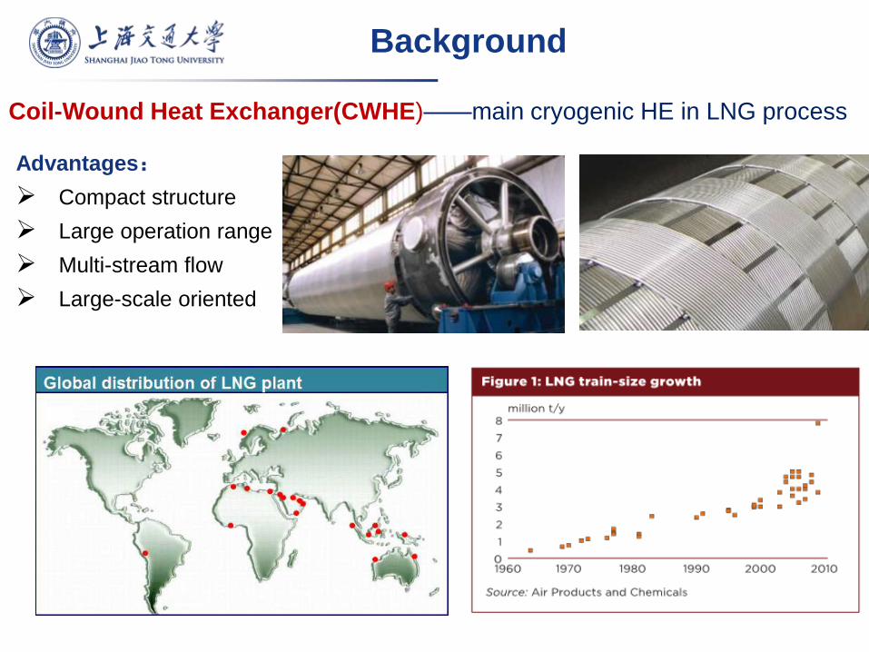
Coil-Wound Heat Exchanger(CWHE)——main cryogenic HE in LNG process
Advantages:
Compact structure
Large operation range
Multi-stream flow
Large-scale oriented
Background
Background
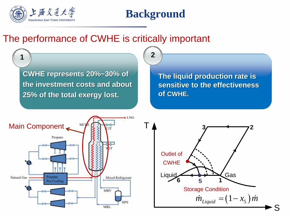
The performance of CWHE is critically important
The liquid production rate is
sensitive to the effectiveness
of CWHE.
1 2
CWHE represents 20%~30% of
the investment costs and about
25% of the total exergy lost.
S
T
4
5
换热器出口工况
储液工况
Liquid Gas
51Liquidm x m
1
23
6
Outlet of
CWHE
Storage Condition
Main Component
Background
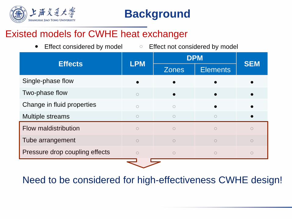
Existed models for CWHE heat exchanger
Effects LPM DPM
SEM Zones Elements
Single-phase flow
Two-phase flow
Change in fluid properties
Multiple streams
Flow maldistribution
Tube arrangement
Pressure drop coupling effects
Effect considered by model Effect not considered by model
Need to be considered for high-effectiveness CWHE design!
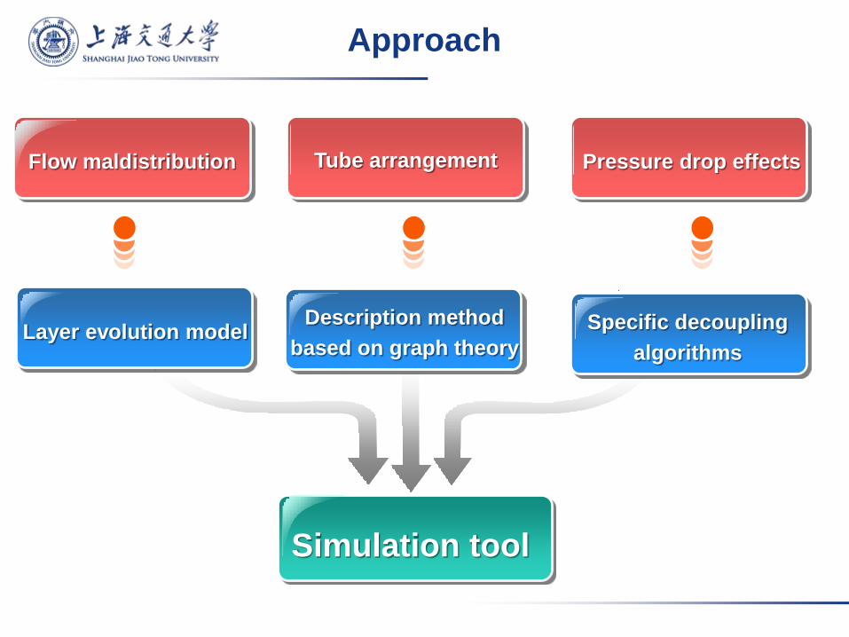
Approach
Flow maldistribution Tube arrangement Pressure drop effects
Simulation tool
Layer evolution model Description method
based on graph theory
Specific decoupling
algorithms
Tube-side
fluid
Shell-side fluid
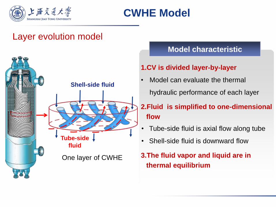
CWHE Model
One layer of CWHE
1.CV is divided layer-by-layer
• Model can evaluate the thermal
hydraulic performance of each layer
2.Fluid is simplified to one-dimensional
flow
• Tube-side fluid is axial flow along tube
• Shell-side fluid is downward flow
3.The fluid vapor and liquid are in
thermal equilibrium
Model characteristic
Layer evolution model

Tube-side fluid
suu p
Shell-side fluid
Mass equation:
Momentum equation: tuu p
t 0u
Energy conservation
t, t,, t, , ss, s, ln
1
N
i ini outi out in
i
Ghh GhhUAT
Fluid #1
Fluid #2
CWHE Model
Governing equations
s 0u Mass equation:
Momentum equation:
0
6 7
3
12
18 19
15
24
28 29
26
16
20 21
13
27
30 31
25
17
22 23
14
5
10 11
21
8 9
4
0
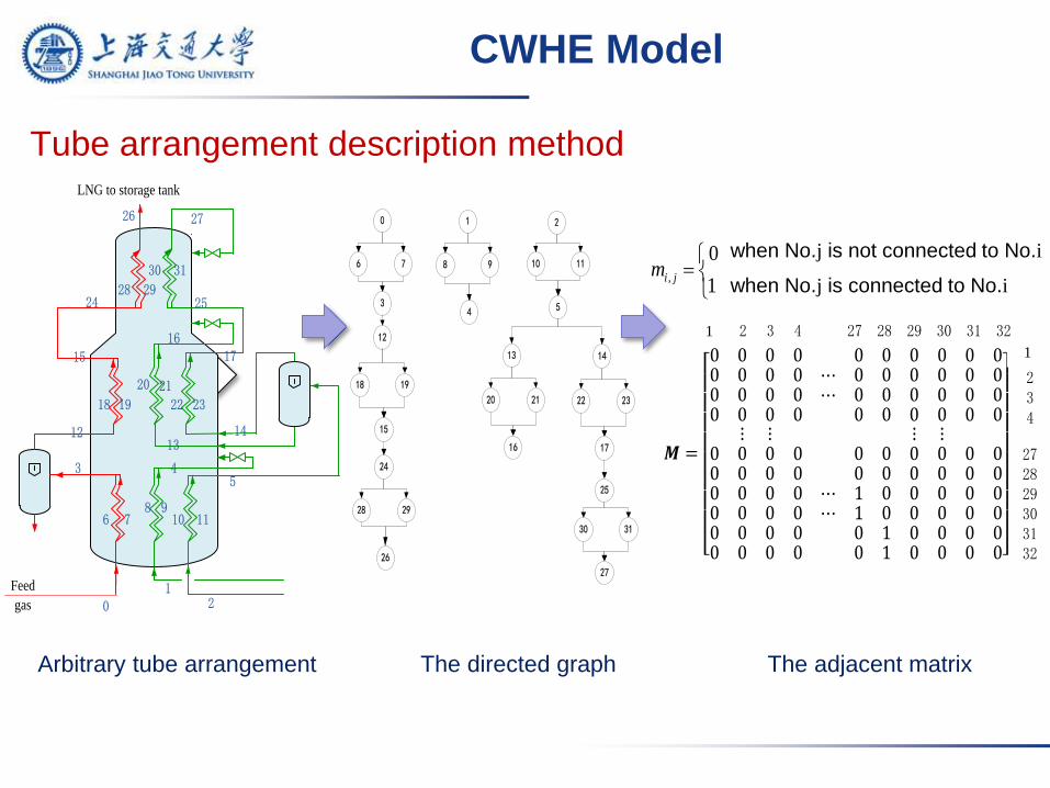
Arbitrary tube arrangement The directed graph The adjacent matrix
01
2
3 45
6 78 9
10 11
1213
14
15
1617
18 19 22 23
20 21
24 25
26 27
28 29
30 31
Feed
gas
LNG to storage tank
CWHE Model
Tube arrangement description method
when No.j is not connected to No.i
when No.j is connected to No.i ,
0
1i jm
𝑴 =
0 0 0 0 0 0 0 0 0 00 0 0 0 ⋯ 0 0 0 0 0 00 0 0 0 ⋯ 0 0 0 0 0 00 0 0 0 0 0 0 0 0 0 ⋮ ⋮ ⋮ ⋮ 0 0 0 0 0 0 0 0 0 00 0 0 0 0 0 0 0 0 00 0 0 0 ⋯ 1 0 0 0 0 00 0 0 0 ⋯ 1 0 0 0 0 00 0 0 0 0 1 0 0 0 00 0 0 0 0 1 0 0 0 0
第1列 2 3 4 27 28 29 30 31 32
第1行
234
27 28 29 30 3132
1
1
01
2
3 45
6 78 9
10 11
1213
14
15
1617
18 19 22 23
20 21
24 25
26 27
28 29
30 31
Feed
gas
LNG to storage tank
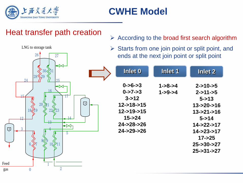
Inlet 0
According to the broad first search algorithm
Starts from one join point or split point, and
ends at the next join point or split point
0->6->3
0->7->3
3->12
12->18->15
12->19->15
15->24
24->28->26
24->29->26
1->8->4
1->9->4
2->10->5
2->11->5
5->13
13->20->16
13->21->16
5->14
14->22->17
14->23->17
17->25
25->30->27
25->31->27
Inlet 1 Inlet 2
CWHE Model
Heat transfer path creation
01
2
3 45
6 78 9
10 11
1213
14
15
1617
18 19 22 23
20 21
24 25
26 27
28 29
30 31
Feed
gas
LNG to storage tank
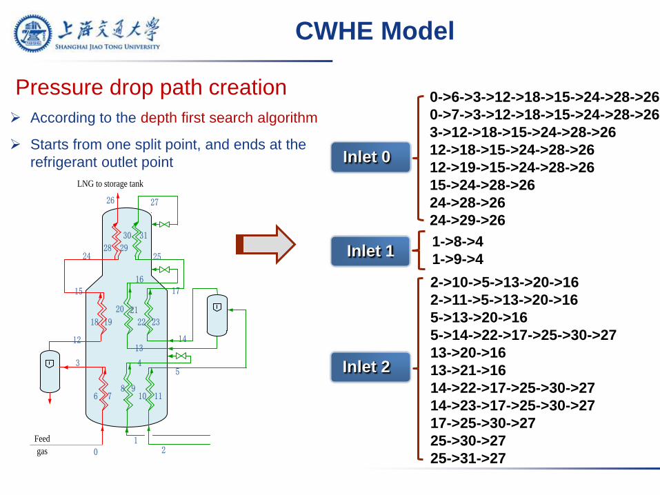
0->6->3->12->18->15->24->28->26
0->7->3->12->18->15->24->28->26
3->12->18->15->24->28->26
12->18->15->24->28->26
12->19->15->24->28->26
15->24->28->26
24->28->26
24->29->26
1->8->4
1->9->4
2->10->5->13->20->16
2->11->5->13->20->16
5->13->20->16
5->14->22->17->25->30->27
13->20->16
13->21->16
14->22->17->25->30->27
14->23->17->25->30->27
17->25->30->27
25->30->27
25->31->27
Inlet 0
Inlet 1
Inlet 2
Pressure drop path creation
CWHE Model
According to the depth first search algorithm
Starts from one split point, and ends at the
refrigerant outlet point
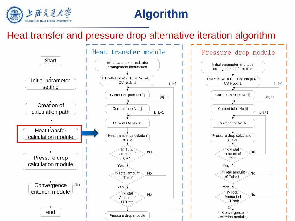
Algorithm
Initial parameter and tube
arrangement information
HTPath No.i=1,Tube No.j=0,CV No.k=1
Current HTpath No.[i]
Current tube No.[j]
Heat transfer calculation
of CV
k>Total
amount of
CV?
j>Total amount
of Tube?
i>Total
Amount of
HTPath
Pressure drop module
Yes
Current CV No.[k]
No
k=k+1
j=j+1
i=i+1
Initial parameter and tube
arrangement information
PDPath No.i=1,Tube No.j=0,CV No.k=1
Current PDpath No.[i]
Current tube No.[j]
Pressure drop calculation
of CV
k>Total
amount of
CV?
j>Total amount
of Tube?
i>Total
Amount of
HTPath
Convergence
criterion module
是
Current CV No.[k]
k=k+1
j=j+1
i=i+1
Pressure drop moduleHeat transfer module
No
No
Yes
No
No
No
Yes
Yes
Start
Initial parameter
setting
Creation of
calculation path
Heat transfer
calculation module
Pressure drop
calculation module
Convergence
criterion module
end
No
Heat transfer and pressure drop alternative iteration algorithm
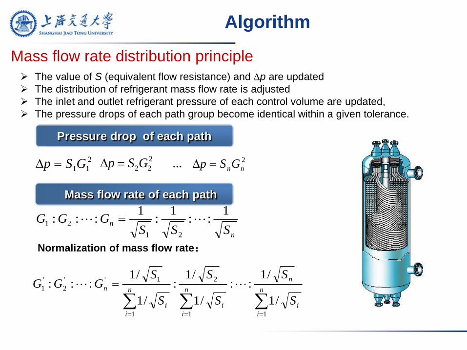
Pressure drop of each path
The value of S (equivalent flow resistance) and p are updated
The distribution of refrigerant mass flow rate is adjusted
The inlet and outlet refrigerant pressure of each control volume are updated,
The pressure drops of each path group become identical within a given tolerance.
2
11GSp 2
2 2 ...p S G 2
nnGSp
Mass flow rate of each path
n
nSSS
GGG1
::1
:1
:::21
21
n
i
i
n
n
i
i
n
i
i
n
S
S
S
S
S
SGGG
11
2
1
1''
2
'
1
/1
/1::
/1
/1:
/1
/1:::
Normalization of mass flow rate:
Algorithm
Mass flow rate distribution principle

Simulation tool
Framework of Simulation tool
Calculation of mixture refrigerant thermal
properties
Decoupling the equations of heat transfer and
pressure drop
A general flow description method based on graph theory
Heat transfer and flow model for tube-side fluid
Results shown as table
Results shown as chart
Results shown as 3D colored graph
Third-party software(Excel,ModeFrontier,...)
Output module
General results
3D/2D interactive graphic interface
Input module
OPenGL and object-oriented
languages Mixed programming
Flow arrangement
Tube-side and shell-side working fluid and refrigerant inlet status
CWHE geometry
Heat transfer and flow model for shell-side fluid
Simulation package
Simulation module
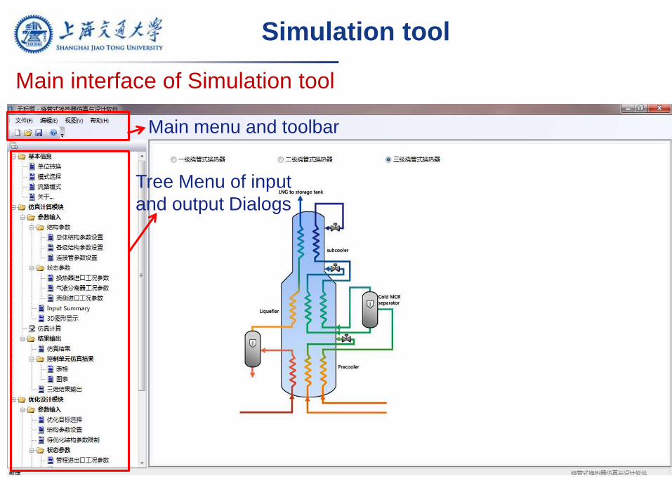
Simulation tool
Main interface of Simulation tool
Main menu and toolbar
Tree Menu of input
and output Dialogs
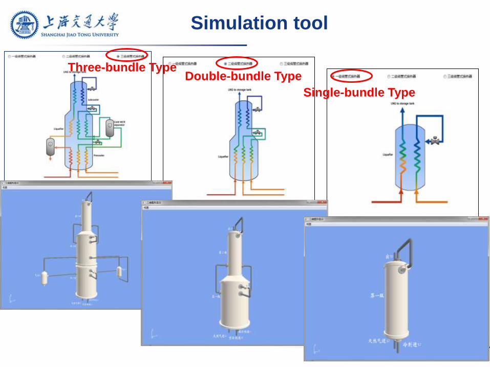
Three-bundle Type
Simulation tool
Double-bundle Type
Single-bundle Type
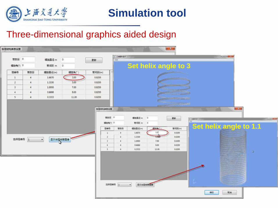
Set helix angle to 3
Set helix angle to 1.1
Simulation tool
Three-dimensional graphics aided design
Simulation tool
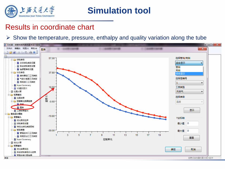
Results in coordinate chart
Show the temperature, pressure, enthalpy and quality variation along the tube
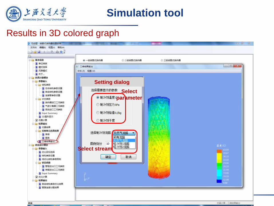
Setting dialog
Select stream
Simulation tool
Results in 3D colored graph
Select
parameter
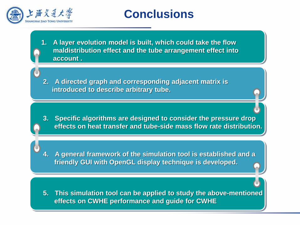
Conclusions
1. A layer evolution model is built, which could take the flow
maldistribution effect and the tube arrangement effect into
account .
2. A directed graph and corresponding adjacent matrix is
introduced to describe arbitrary tube.
3. Specific algorithms are designed to consider the pressure drop
effects on heat transfer and tube-side mass flow rate distribution.
4. A general framework of the simulation tool is established and a
friendly GUI with OpenGL display technique is developed.
5. This simulation tool can be applied to study the above-mentioned
effects on CWHE performance and guide for CWHE