
A Review of Research on Shear Strength Decay in Members under Load Reversals
Rémy Lequesne and Gustavo Parra-Montesinos
Synopsis: Early research on the behavior of frame members subjected to reversed cyclic displacements has been
reviewed, with an emphasis on the phenomenon of shear strength decay. Information is provided about variables that
affect shear strength decay and measures that can be taken to mitigate this phenomenon, which should be of interest
to students and structural engineers learning or involved in earthquake-resistant design of reinforced concrete
structures.
Starting in the 1950s, the effect of reversing the loading direction on the flexural response of beams was investigated
experimentally. Among other findings, tests showed that single and repeated reversals of load had little influence on
flexural strength, but that loading history does influence the deformation capacity and stiffness of members. Although
several researchers emphasized the importance of providing adequate transverse reinforcement confining the member
core, the role of shear stresses on the response of frame members was not well understood until the early 1970s. Tests
by Brown and Jirsa, Wight and Sozen, and Popov, Bertero and Krawinkler, showed that member strength can decay
under reversals of load if shear stress demands are large or if inadequate transverse reinforcement is provided. In
particular, it was shown by Wight and Sozen that maintaining the integrity of the concrete core through use of closely
spaced transverse reinforcement with enough area to resist the entire shear demand without yielding is essential,
although not necessarily sufficient. Changes to the ACI Building Code aimed at minimizing shear strength decay were
first adopted in 1983 and have remained in subsequent editions of the Code with relatively minor changes.
Keywords: shear, strength decay, beam, column, seismic

Rémy D. Lequesne, MACI, is Assistant Professor of Civil, Environmental and Architectural Engineering at the
University of Kansas. He is Secretary of Joint ACI-ASCE Committee 408, Bond and Development of Steel
Reinforcement, and member of ACI Sub-Committee 318-J, Joints and Connections, and Joint ACI-ASCE Committee
352, Joints and Connections in Monolithic Concrete Structures. His interests include earthquake resistant design and
the behavior of reinforced concrete and fiber reinforced concrete members.
Gustavo J. Parra-Montesinos, FACI, is the C.K. Wang Professor of Structural Engineering at the University of
Wisconsin-Madison. He is a member of ACI Committee 318, Structural Building Code, and Chair of ACI Sub-
Committee 318-J, Joints and Connections. He is also Chair of Joint ACI-ASCE Committee 352, Joints and
Connections in Monolithic Concrete Structures, and member of Joint ACI-ASCE Committee 335, Composite and
Hybrid Structures. His research interests include the behavior and design of reinforced concrete, fiber reinforced
concrete, and hybrid steel-concrete structures.
INTRODUCTION
In the design of reinforced concrete earthquake-resisting frame members, it is critical that shear distress be limited in
order to ensure acceptable deformation capacity and reduce damage. Accordingly, several ACI Building Code1
provisions for beams and columns of frames categorized as “special moment frames” are aimed at minimizing shear
distress. Pertinent requirements include using a capacity design approach to calculate demand, neglecting any
contribution of the concrete to nominal shear strength in beams, and limiting hoop spacing to one-fourth of the
effective (beams) or overall (columns) member depth. These provisions are largely based on findings from early
research aimed at understanding the behavior of frame members subjected to cycles of load reversals.
The aim of this paper is to review relevant research on the behavior of frame members under earthquake-type demands,
beginning with the first tests of flexural members subjected to fully reversed loads and ending with the 1983 ACI
Building Code2, as it was the first ACI Code edition to incorporate several provisions aimed at minimizing shear
strength decay. This paper describes the basis for pertinent ACI Building Code provisions (other code or design
documents were not included in this review), emphasizes the importance of low shear stress demands, and highlights
reinforcement detailing options that have been shown to improve member behavior. This review should therefore be
of interest to students and structural engineers, particularly those learning or involved in earthquake-resistant design
of reinforced concrete structures.
BEHAVIOR OF FLEXURAL MEMBERS UNDER REVERSALS OF LOAD
The first studies of frame members under reversals of load were focused on their effect on flexural behavior. The
specimens were therefore designed so that brittle mechanisms such as shear and bond would not dominate behavior.
Findings showed that reversals of load had little effect on flexural strength, but that loading history could influence
deformation capacity and reduce member stiffness. Although shear stress demands were often low, the researchers
emphasized the importance of preventing shear failures and confining the member core. The following describes
pertinent early studies on the flexural behavior of members under load reversals.
McCollister, Siess, and Newmark
In 1954, McCollister, Siess, and Newmark3 reported results from six beam specimens loaded monotonically until
failure after previously undergoing a single “push” in the opposite direction. Although this loading history is more
representative of a blast than an earthquake (one reversal of load), the study identified several aspects of behavior that
are typical of specimens subjected to repeated reversals of load. The specimens, which had a 6 by 12 in. (150 by 300
mm) cross-section, were supported by rollers spaced 9 ft (2740 mm) apart and loaded through a column stub at
midspan (Fig. 1). Because the test setup could only apply force in one direction, the specimens were removed after
loading in one direction, inverted, and placed back into the test frame for loading in the opposite direction. To ensure
a flexure-dominated response, transverse reinforcement was provided “that would be capable of carrying all of the
predicted maximum shear force at a unit stress not in excess of [its] yield point,” resulting in specimens that had no
shear force attributed to the concrete in design (i.e., 𝑉𝑐 = 0, where 𝑉𝑐 is the shear strength attributed to the concrete).
Figure 2 shows the load versus deflection response of Specimen T-12I, which had previously been loaded in the
opposite direction, alongside the result from Specimen T-2, a comparable specimen loaded monotonically to failure

without a previous push. As shown in Fig. 2, the reversal of load did not significantly influence the strength or
deformation capacity of the specimen. However, the preceding loading in the opposite direction did cause the definite
yield point observed in the test of Specimen T-2 to be replaced with a gradual change in slope, due to the Bauschinger
effect. McCollister, Siess, and Newmark also observed “faulting across nearly vertical cracks near the column stubs.
These cracks, which extended throughout the depth of the beams, were developed as a result of tension forces having
been present in both the upper and lower sections of the beam.” This faulting, frequently referred to as sliding, was
most pronounced in specimens loaded to near their maximum flexural strength in one direction prior to reversing the
direction of loading.
Figure 1 – Schematic of test setup used by McCollister, Siess, and Newmark (Ref. 3).
Figure 2 – Load versus deflection for specimens subjected to monotonic (T-2) and reversed (T-12I) loads
(Ref. 3), 1 kip = 4.45 kN, 1 in. = 25 mm ≈ 2.0% chord rotation.
Burns and Siess
As part of an investigation aimed at studying the load-deformation response of beam-column connections, Burns and
Siess4, 5 tested three specimens under repeated and fully reversed loads. The beam specimens, which were 8 in. (200
mm) wide with an effective depth of either 10 or 18 in. (250 or 450 mm), were loaded through a column stub at
midspan and supported by rollers at their ends. The influence of shear on member behavior was minimized by keeping
the shear stresses low (below 3√𝑓𝑐′ [psi], or 0.25√𝑓𝑐
′ [MPa]) and providing enough transverse reinforcement to resist
the entire imposed shear without yielding. The force versus deflection response of Specimen J-3 is shown in Fig. 3.
Burns and Siess reported that flexural strength is not significantly affected by load reversals, but that stiffness and
deformation capacity may be. With respect to transverse reinforcement, the study found that “closed ties to support
the steel as well as to confine the concrete core” are essential, and that when closed ties are provided, “under-reinforced
beams possess remarkable ductility.” Even though shear stresses were low, Burns and Siess noted that “some members
failed with a mode of failure involving shear” that limited the deformability of the specimens compared to specimens

dominated by flexure. The explanation provided for the failures “involving shear” was that cracks developed at an
inclination greater than 45 degrees within the plastic zone that resulted in fewer ties engaged in resisting shear.
Figure 3 – Load versus deflection for Specimen J-3 (Ref. 4),
1 kip = 4.45 kN, 1 in. = 25 mm ≈ 1.5% chord rotation.
Figure 4 – Shear diagram for a beam developing its moment strength at both ends and gravity load (Ref. 6).
The Blume, Newmark, and Corning book and 1963 ACI Building Code
In 1961, Blume, Newmark, and Corning6 published a book titled “Design of Multistory Reinforced Concrete Buildings
for Earthquake Motions” that covered aspects of seismology, dynamics, and design of both reinforced concrete
members and structural systems that are essential in earthquake-resistant design.
An important contribution of the book is the recognition that the shear demand imposed on members by earthquake
motions are a function of the flexural strength of the member. This capacity design approach to calculating shear
demands is shown in Fig. 4 (Fig. 6.1 in Ref. 6). The proposed approach included effects of gravity loads (𝑊 in Fig.
4) and assumed that moments develop at each end of a member (𝑀1 and 𝑀2 in Fig. 4) in response to earthquake
motions that induce double curvature. Unlike today’s practice, use of the nominal flexural strength, rather than the
probable or expected strength, was recommended.

For provision of transverse reinforcement, Blume, Newmark, and Corning recommended limiting the spacing of
transverse hoops (referred to as stirrup-ties) to the lesser of one-half the effective depth (𝑑 2⁄ ), 16 times the
longitudinal bar diameter, and 12 in. (300 mm). It was also recommended to limit shear stress demands to below
6√𝑓𝑐′ [psi] (0.5√𝑓𝑐
′ [MPa]) to avoid congestion of reinforcement. A decade later, experiments would demonstrate that
limiting shear stress demands to below 6√𝑓𝑐′ [psi] (0.5√𝑓𝑐
′ [MPa]) is critical for delaying shear strength decay.
In contrast to the Blume, Newmark, and Corning book, the 1963 ACI Building Code7 did not include special provisions
for members expected to undergo earthquake-induced deformations. In frames, nominal shear strength (𝑉𝑛) was
calculated using Eq. 1, with an upper shear stress limit of 10√𝑓𝑐′ [psi] (0.83√𝑓𝑐
′ [MPa]). Transverse reinforcement
spacing was limited to one-half the effective depth (𝑑 2⁄ ) for shear stresses up to 6√𝑓𝑐′ [psi] (0.5√𝑓𝑐
′ [MPa]) and one-
fourth the effective depth (𝑑 4⁄ ) for higher stress demands. Where compression reinforcement was required, stirrup/tie
spacing was further limited to the lesser of 16 times the longitudinal bar diameter and 48 tie bar diameters.
𝑉𝑛 = 𝑉𝑐 + 𝑉𝑠 = (1.9√𝑓𝑐
′ + 2500𝜌𝑤𝑉𝑑
𝑀) 𝑏𝑑 +
𝐴𝑣𝑓𝑦𝑑
𝑠 [psi]
𝑉𝑛 = 𝑉𝑐 + 𝑉𝑠 = (0.16√𝑓𝑐′ + 17
𝜌𝑤𝑉𝑑
𝑀) 𝑏𝑑 +
𝐴𝑣𝑓𝑦𝑑
𝑠 [MPa]
Eq. 1
In Eq. 1, 𝑉𝑐 and 𝑉𝑠 are the shear strength attributed to the concrete and transverse reinforcement, respectively, 𝑓𝑐′ is the
concrete compressive strength, 𝜌𝑤 is the longitudinal reinforcement ratio, 𝑉 and 𝑀 are the shear force and moment
demand at the critical section, 𝑏 and 𝑑 are the width and effective depth of the member, 𝐴𝑣 and 𝑓𝑦 are the cross-
sectional area and yield strength of the transverse reinforcement, and 𝑠 is the spacing of transverse reinforcement.
Subsequent studies
In the 1960s, studies investigating the effect of load reversals on the flexural strength of singly and doubly reinforced
beams8, 9, as well as single-bay frames10, supported previous findings that load reversals have a negligible impact on
flexural strength. Shear mechanisms did not play a significant role in either study because the former (Ref. 8 and 9)
focused on the constant moment region of beams subjected to 4-point loads, and the latter (Ref. 10) on highly slender
specimens. In their report of the single-bay frame tests, Bertero and McClure did, however, emphasize the importance
of suppressing non-ductile failure mechanisms related to instability, shear, and bond. The Bertero and McClure study
also found that reversals of load can significantly degrade the stiffness of frame members, although their findings may
have overstated the effect because significant degradation of the bond between reinforcing bars and concrete
developed. The loss of bond, which contributed significantly to the loss of lateral stiffness, may have been exacerbated
by the small scale of the test specimens (members had 2-7/8 by 4 in., or 72 by 100 mm, cross-sections).
Tests were conducted in Japan to investigate the behavior of axially loaded members subjected to repeated
displacement reversals11-13. Results showed that axial thrust must remain below the balanced point if member ductility
is important. The tests also showed that, when subjected to cyclic displacement reversals, specimens can exhibit
pinched hysteresis characterized by a region of low stiffness near the zero shear force axis. Furthermore, results from
these tests indicated that shear-related mechanisms may become dominant and limit the deformability of the specimens
if not adequately suppressed. To limit the influence of shear mechanisms, the researchers recommended a minimum
shear span to depth ratio of 2 and a minimum transverse reinforcement ratio of 0.6% (as summarized in Ref. 14).
Among other findings, tests of seven beam-column connection subassemblies by Hanson and Conner15 clearly
demonstrated the importance of hoops to both resist shear demands and provide confinement to the core of flexural
members subjected to multiple displacement reversals.
UNDERSTANDING AND MITIGATING SHEAR STRENGTH DECAY
As described previously, early studies of the behavior of frame members under cyclic displacement reversals were
aimed principally at understanding flexural response. To ensure a flexural failure mode, specimens were often
designed with low shear stresses and provided with transverse reinforcement at least equal to that required to resist
the entire shear demand. Nonetheless, Burns and Siess4 noted that the deformation capacity of flexural members
subjected to displacement reversals could be limited by a “mode of failure involving shear” that developed after
yielding of the flexural reinforcement. Several studies aimed at understanding this shear-related mode of failure were

published in the early 1970s that significantly advanced the understanding of the role of shear in the response of
flexural members subjected to cyclic displacement reversals.
Brown and Jirsa
Brown and Jirsa16-17 were perhaps the first to explicitly recognize the significant influence of shear strength decay on
the load-deformation response of frame members. Their tests of reinforced concrete beams under cyclic displacement
reversals showed that the “behavior of the specimens was influenced primarily by shear,” and that “changes in
geometry or load history which reduced the shear force or increased the shear capacity… significantly increased the…
number of cycles to failure.”
The test program consisted of twelve reinforced concrete beams cantilevered from a large concrete block at one end
(Fig. 5). The beams had a 6 by 12 in. (150 by 300 mm) cross-section, equal areas of longitudinal tension and
compression reinforcement (𝜌𝑤 of either 0.015 or 0.026), and No. 3 (10 mm) hoops with a spacing that varied among
the specimens. Variables of interest included the effect of loading type (monotonic, unidirectional cycling, and
reversed cycling), imposed displacement amplitude (either 5 or 10 times the yield deflection), hoop spacing, and shear
stress level.
Although specimens subjected to monotonic and uni-directional cycling exhibited failure modes dominated by flexure,
test results showed that the response of specimens to fully reversed cyclic loads was heavily influenced by shear
demands. In Fig. 6, the load versus deflection responses of two similar specimens are plotted. The specimens were
subjected to reversed cyclic displacements to approximately 11% drift and an approximate shear stress magnitude of
either 200 or 400 psi (1.4 or 2.8 MPa). The difference in imposed shear stresses was a result of different shear spans
(six and three times the effective depth, respectively), and not differences in specimen cross-section or reinforcement.
In both cases, the shear strength provided by hoops (assuming a horizontal shear crack projection of d) exceeded the
demand. As can be seen in Fig. 6, resistance to lateral loads degraded at a much greater rate in Specimen 88-34-RV10-
30 [Fig. 6(b)], than in Specimen 88-35-RV10-60 [Fig. 6(a)].
Figure 5 – Schematic of beam specimens tested by Brown and Jirsa (Ref. 17).

(a) Shear stress of 200 psi (1.4 MPa) (b) Shear stress of 400 psi (2.8 MPa)
1 in. ≈ 1.7% chord rotation 1 in. ≈ 3.3% chord rotation
Figure 6 – Load versus deflection response of beams subjected to cyclic displacement reversals (Ref. 17),
1 kip = 4.45 kN, 1 in. = 25 mm.
Figure 7 – Moment versus rotation response of beam subjected to cyclic displacement reversals (Ref. 17),
100 in.-kip = 11.3 m-kN.
The importance of shear-related mechanisms in the strength decay observed in the test of Specimen 88-34-RV10-30
is further illustrated in Fig. 7, which shows the moment developed at the support face plotted versus measured rotation.
That the measured rotations decreased significantly while imposed deflections remained approximately constant (Fig.
6(b)) is evidence of the increasingly dominant role of shear deformations late in the test. The authors attributed this
strength decay to “abrasion over a surface formed by a combination of diagonal tension cracks and nearly vertical
flexural tension cracks resulting from load reversals.”
Brown and Jirsa concluded that larger deformation demands and reductions of the shear span (and thus increases in
shear demand) resulted in a smaller number of cycles sustained prior to failure. To mitigate these effects, they showed
that “reducing the stirrup spacing increased significantly the number of cycles to failure.” In addition, the authors
noted that pinching of the hysteresis near zero load, as is evident in Fig. 6(b), “was the result of shear deformations
and of a reduced stiffness during closure of flexural cracks formed in the previous half-cycle.”

Wight and Sozen
Shear strength decay under reversals of load was studied by Wight and Sozen14, 18 in members with and without axial
thrust. A series of twelve specimens was tested using the setup shown in Fig. 8. An axial load of between zero and
one-half of the calculated balanced load was applied and held constant throughout each test. Lateral loads were applied
with hydraulic rams at each end of the specimen in opposite directions, such that a reversal of moment developed
across the central stub.
Figure 8 – Schematic of test setup used by Wight and Sozen (Ref. 18),
1 in. = 25 mm.
An important feature of the test program was that the shear capacity, calculated as the sum of terms representing
contributions from the concrete and transverse reinforcement (Eq. 2), varied between 1 and 3 times the expected
demand. Relatively high shear stresses, on the order of 6√𝑓𝑐′ [psi] (0.5√𝑓𝑐
′ [MPa]), were imposed.
𝑉𝑛 = 𝑉𝑐 + 𝑉𝑠 = 2.0 (1 + 0.0005
𝑁𝑢
𝐴𝑔
) 𝑏𝑑√𝑓𝑐′ +
𝐴𝑣𝑓𝑦𝑑
𝑠 [psi]
𝑉𝑛 = 𝑉𝑐 + 𝑉𝑠 = 0.17 (1 + 0.0005𝑁𝑢
𝐴𝑔
) 𝑏𝑑√𝑓𝑐′ +
𝐴𝑣𝑓𝑦𝑑
𝑠 [MPa]
Eq. 2
In Eq. 2, the terms are defined as in Eq. 1, except 𝑁𝑢 is the axial thrust and 𝐴𝑔 is the gross cross-sectional area.
Results from three of the tests are shown in Fig. 9, plotted as shear force versus deflection. The curves represent
specimens with an axial load of 40 kip (180 kN, or approximately 0.1𝐴𝑔𝑓𝑐′) and varied amounts of transverse
reinforcement. The top curve resulted from the test of a specimen that had a shear capacity, calculated using Eq. 2,
that was approximately equal to the expected demand. It is clear that shear decay played a dominant role in the
response of the specimen, which lost half its capacity after three cycles at a chord rotation of approximately 2.5%, or
1 in. (25 mm) of deflection. The specimen represented by the middle curve fared somewhat better, although shear
strength decay was still a dominant feature of the response. This specimen had transverse reinforcement provided to
carry 70% of the expected capacity, resulting in a calculated nominal shear strength (Eq. 2) that was 1.2 times the
expected demand. The third curve shown resulted from the test of a member that had a nominal shear strength that
was 2.5 times the expected demand (𝑉𝑠 alone was approximately twice the demand). This specimen exhibited little
shear decay after several loading cycles to a chord rotation of approximately 5%, or a deflection of 2 in. (50 mm), as
indicated by strength retention and minimal pinching of the hysteresis. These results show the important correlation
between amount of transverse reinforcement (𝑉𝑠 𝑉𝑢⁄ ) and shear strength degradation. Other results, not shown here,
indicated that the “decay in shear strength is less in elements with higher axial loads, everything else being equal.”
However, this finding is limited to members that, like the test specimens, are subjected to axial thrusts with a
magnitude that is less than the balanced load.

Figure 9 – Load versus deflection response of columns subjected to cyclic displacement reversals (Ref. 14),
1 kip = 4.45 kN, 1 in. = 25 mm ≈ 2.5% chord rotation.
Figure 10 – Illustration of shear force versus deflection (Ref. 14).
Through observations and measurements, Wight and Sozen described the mechanisms that contribute to shear strength
decay. Cracking and spalling caused by repeated reversals of load compromise the ability of the compression zone to
transfer shear. Fig. 10, which qualitatively shows the shear demand and resistance to shear plotted versus displacement
ductility, indicates a shift in shear resistance mechanisms towards one dominated by truss action. Because the ability
of the specimen to resist shear in excess of that carried by hoops diminishes, they recommended that “if reinforced
concrete elements are designed to resist earthquake effects by energy dissipation in the inelastic range, the transverse
reinforcement must be designed to carry the entire shear.”
Furthermore, Wight and Sozen showed that “use of closely spaced hoops designed to carry all of the shear does not
necessarily prevent shear failures.” Because hoops are effective in resisting shear only because they form part of a
truss mechanism, “all of the loads applied to a reinforced concrete members are ultimately carried by the concrete and

if the concrete does not stay intact, the strength of the reinforcement cannot be developed.” Wight and Sozen
recommended limiting the spacing of hoops to no more than one-fourth of the effective depth, and designing members
so as to prevent yielding of the transverse reinforcement. If the hoops yield, “the concrete section… becomes distorted.
As a result, the shear strength decays.”
Popov, Bertero and Krawinkler
Popov, Bertero and Krawinkler19 also addressed the shear strength decay phenomenon in a study of RC beams under
large reversals of load. Fig. 11 shows results from two beam specimens, plotted as applied load versus deflection.
Both specimens were subjected to relatively high shear stress demands of 5 to 6√𝑓𝑐′ [psi] (0.42 to 0.50√𝑓𝑐
′ [MPa]).
Beam 35 was reinforced so that the calculated nominal shear strength (Eq. 2, with 𝑁𝑢 = 0) was approximately equal
to the shear demand. The specimen failed abruptly with a mode described as “predominantly of a shear diagonal
tension type… [that] occurred after some flexural yielding developed.” Beam 43 which was reinforced so that the
calculated shear strength provided by stirrups alone exceeded the demand by 25%, exhibited little decay in shear
strength despite multiple reversals of load to a tip deflection exceeding 3 in., or 75 mm (chord rotations of
approximately 4%). These findings support neglecting the contribution of the concrete when calculating the nominal
shear strength in regions of members expected to undergo multiple large reversals of load.
(a) (𝑉𝑐 + 𝑉𝑠) 𝑉𝑢⁄ ≈ 0.92 (b) (𝑉𝑐 + 𝑉𝑠) 𝑉𝑢⁄ ≈ 1.61
𝑉𝑠 𝑉𝑢⁄ ≈ 0.52 𝑉𝑠 𝑉𝑢⁄ ≈ 1.26
Figure 11 – Load versus deflection response of beams subjected to cyclic displacement reversals (Ref. 20),
1 kip = 4.45 kN, 1 in. = 25 mm ≈ 1.3% chord rotation.
Closer evaluation of the results from Beam 43 shows that some pinching of the hysteresis developed at larger chord
rotations. This was associated with “considerable grinding of the aggregate and mortar… along the two main diagonal
cracks,” leading to a sliding shear failure. In either specimen, it was shown that shear distortion may be an important
deformation component after multiple reversals of load.
Popov, Bertero and Krawinkler also noted that shear decay can be significant in members under shear stress demands
of 6√𝑓𝑐′ [psi] (0.5√𝑓𝑐
′ [MPa]), which is significantly less than the upper limit of 10√𝑓𝑐′ [psi] (0.83√𝑓𝑐
′ [MPa]) permitted in design. They recommended limiting shear stress demands in regions of members expected to undergo
multiple displacement reversals to no more than 6√𝑓𝑐′ [psi] (0.5√𝑓𝑐
′ [MPa]).

Figure 12 – Beam specimens tested by Bertero and Popov (Ref. 20),
1 in. = 25 mm.
Figure 13 – Load versus deflection response of a diagonally reinforced beam (Ref. 20),
1 in. = 1.3% chord rotation.
In subsequent studies, Bertero and Popov20 showed that diagonally oriented reinforcement in the expected plastic
hinging region of beams can significantly improve the response to repeated reversals of load. This finding followed
tests conducted in New Zealand that showed the significant benefit derived from diagonally oriented reinforcement in
coupling beams21. A diagram of one of the specimens tested by Bertero and Popov is shown in Fig. 12. The test result
is shown in Fig. 13 as a plot of force versus deflection. The excellent deformation capacity (approximately 5% chord
rotation) and full hysteresis with no pinching until the last few loading cycles are evidence that shear strength decay
mechanisms, including sliding, were significantly delayed (or prevented) by the diagonal reinforcement. Although
highly effective, this reinforcement layout would be difficult to construct.
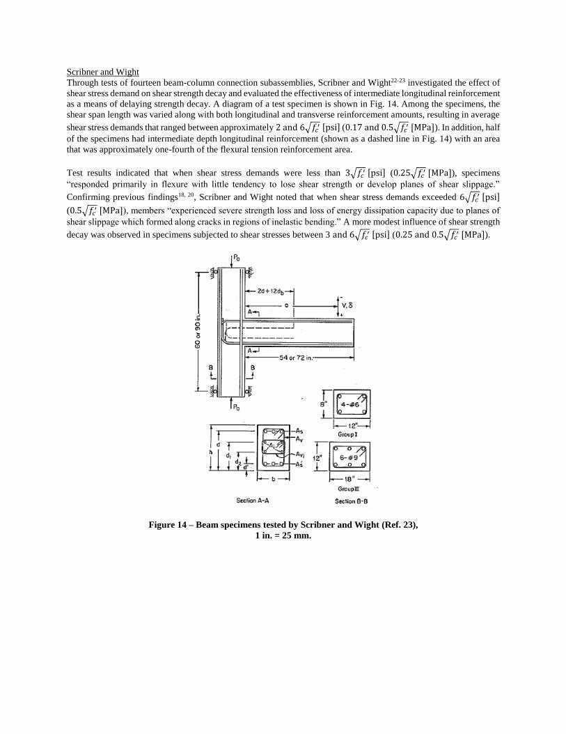
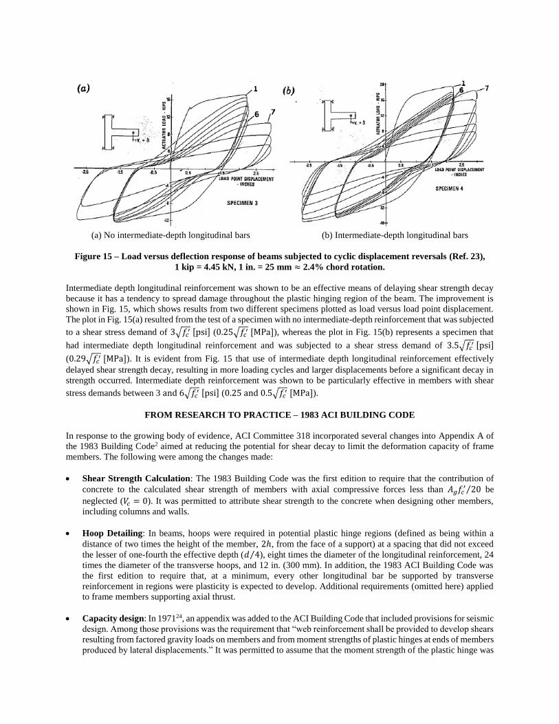
Scribner and Wight
Through tests of fourteen beam-column connection subassemblies, Scribner and Wight22-23 investigated the effect of
shear stress demand on shear strength decay and evaluated the effectiveness of intermediate longitudinal reinforcement
as a means of delaying strength decay. A diagram of a test specimen is shown in Fig. 14. Among the specimens, the
shear span length was varied along with both longitudinal and transverse reinforcement amounts, resulting in average
shear stress demands that ranged between approximately 2 and 6√𝑓𝑐′ [psi] (0.17 and 0.5√𝑓𝑐
′ [MPa]). In addition, half
of the specimens had intermediate depth longitudinal reinforcement (shown as a dashed line in Fig. 14) with an area
that was approximately one-fourth of the flexural tension reinforcement area.
Test results indicated that when shear stress demands were less than 3√𝑓𝑐′ [psi] (0.25√𝑓𝑐
′ [MPa]), specimens
“responded primarily in flexure with little tendency to lose shear strength or develop planes of shear slippage.”
Confirming previous findings18, 20, Scribner and Wight noted that when shear stress demands exceeded 6√𝑓𝑐′ [psi]
(0.5√𝑓𝑐′ [MPa]), members “experienced severe strength loss and loss of energy dissipation capacity due to planes of
shear slippage which formed along cracks in regions of inelastic bending.” A more modest influence of shear strength
decay was observed in specimens subjected to shear stresses between 3 and 6√𝑓𝑐′ [psi] (0.25 and 0.5√𝑓𝑐
′ [MPa]).
Figure 14 – Beam specimens tested by Scribner and Wight (Ref. 23),
1 in. = 25 mm.
(a) No intermediate-depth longitudinal bars (b) Intermediate-depth longitudinal bars
Figure 15 – Load versus deflection response of beams subjected to cyclic displacement reversals (Ref. 23),
1 kip = 4.45 kN, 1 in. = 25 mm ≈ 2.4% chord rotation.
Intermediate depth longitudinal reinforcement was shown to be an effective means of delaying shear strength decay
because it has a tendency to spread damage throughout the plastic hinging region of the beam. The improvement is
shown in Fig. 15, which shows results from two different specimens plotted as load versus load point displacement.
The plot in Fig. 15(a) resulted from the test of a specimen with no intermediate-depth reinforcement that was subjected
to a shear stress demand of 3√𝑓𝑐′ [psi] (0.25√𝑓𝑐
′ [MPa]), whereas the plot in Fig. 15(b) represents a specimen that
had intermediate depth longitudinal reinforcement and was subjected to a shear stress demand of 3.5√𝑓𝑐′ [psi]
(0.29√𝑓𝑐′ [MPa]). It is evident from Fig. 15 that use of intermediate depth longitudinal reinforcement effectively
delayed shear strength decay, resulting in more loading cycles and larger displacements before a significant decay in
strength occurred. Intermediate depth reinforcement was shown to be particularly effective in members with shear
stress demands between 3 and 6√𝑓𝑐′ [psi] (0.25 and 0.5√𝑓𝑐
′ [MPa]).
FROM RESEARCH TO PRACTICE – 1983 ACI BUILDING CODE
In response to the growing body of evidence, ACI Committee 318 incorporated several changes into Appendix A of
the 1983 Building Code2 aimed at reducing the potential for shear decay to limit the deformation capacity of frame
members. The following were among the changes made:
Shear Strength Calculation: The 1983 Building Code was the first edition to require that the contribution of
concrete to the calculated shear strength of members with axial compressive forces less than 𝐴𝑔𝑓𝑐′ 20⁄ be
neglected (𝑉𝑐 = 0). It was permitted to attribute shear strength to the concrete when designing other members,
including columns and walls.
Hoop Detailing: In beams, hoops were required in potential plastic hinge regions (defined as being within a
distance of two times the height of the member, 2ℎ, from the face of a support) at a spacing that did not exceed
the lesser of one-fourth the effective depth (𝑑 4⁄ ), eight times the diameter of the longitudinal reinforcement, 24
times the diameter of the transverse hoops, and 12 in. (300 mm). In addition, the 1983 ACI Building Code was
the first edition to require that, at a minimum, every other longitudinal bar be supported by transverse
reinforcement in regions were plasticity is expected to develop. Additional requirements (omitted here) applied
to frame members supporting axial thrust.
Capacity design: In 197124, an appendix was added to the ACI Building Code that included provisions for seismic
design. Among those provisions was the requirement that “web reinforcement shall be provided to develop shears
resulting from factored gravity loads on members and from moment strengths of plastic hinges at ends of members
produced by lateral displacements.” It was permitted to assume that the moment strength of the plastic hinge was
equal to the calculated nominal moment strength. The 1983 ACI Building Code was the first edition to require
that the probable moment capacity, calculated assuming a reinforcement stress of at least 1.25𝑓𝑦, be used to
determine the shear demand in frame members located in regions of high seismic risk.
Collectively, these changes reduced the likelihood that transverse reinforcement would yield in beams subjected to
cyclic displacement demands. Even if the transverse reinforcement yields, these changes ensured there would be
significantly more confinement of the member core than before. Experimental data indicated that such changes would
improve the deformation capacity of members and reduce the extent of damage expected to develop in response to
seismically induced demands. These provisions remain in the current ACI Building Code with minor modifications
(in 2014, the maximum hoop spacing in beams of special moment frames is limited to the lesser of one-fourth the
effective depth (𝑑 4⁄ ), six times the diameter of the longitudinal reinforcement, and 6 in., or 150 mm).
SUMMARY
Early research on the behavior of frame members subjected to cyclic displacement reversals was reviewed, with an
emphasis on findings related to shear strength decay. The scope of the review ended with the 1983 ACI Building
Code, which was the first edition of the ACI Code to include several provisions aimed at mitigating shear strength
decay in flexural members. The following is a summary of major findings.
Reduced member strength, pinching of the hysteresis, and an increase in the contribution of shear sliding and
distortion to overall member deformation were found to indicate a decay in shear strength under reversals of
load. Even if strength is maintained, it has been shown that shear mechanisms can contribute significantly to
overall member deformation.
Closely spaced hoops with sufficient strength to resist probable shear demands reduce the influence of shear
strength decay on member behavior. However, “the use of closely spaced stirrups that are designed to carry
all of the shear does not necessarily prevent shear failures.”14 This is because “all of the loads applied to a
reinforced concrete member are ultimately carried by the concrete and if the concrete does not stay intact,
the strength of the reinforcement cannot be developed.”14 Confinement of the core of the member is therefore
essential to minimizing the influence of shear decay mechanisms.
Shear stress demand is a primary factor governing shear strength decay. Provided there is adequate transverse
reinforcement, the behavior of members with shear stresses below 3√𝑓𝑐′ [psi] (0.25√𝑓𝑐
′ [MPa]) will
experience little or no shear strength decay. It is likely that shear strength decay will be an important feature
of the response to cyclic displacements in members subjected to shear stress in excess of 6√𝑓𝑐′ [psi]
(0.5√𝑓𝑐′ [MPa]), even when a significant amount of transverse hoops is provided at a close spacing.
The number of loading cycles and magnitude of the displacement demand tend to increase the likelihood that
shear strength decay will influence the response, whereas moderate levels of axial load (less than the balanced
load) tend to reduce shear strength decay.
Inclined reinforcement located within the expected plastic hinging region has been shown to delay or prevent
shear sliding and strength decay. Likewise, intermediate depth longitudinal reinforcement with an area that
is approximately one-fourth of the area of flexural tension reinforcement has been shown to delay shear
strength decay by spreading damage and delaying localization of distress.
ACKNOWLEDGEMENTS
The writers would like to acknowledge the significant contributions of James K. Wight to the understanding of
behavior and design of reinforced concrete structures. Through his research and service, Jim has helped shape current
design practice. Through his teaching and mentorship, he has furthered the development of both students and
colleagues. The writers are grateful to consider him a colleague and a friend.

REFERENCES
1. ACI Committee 318, (2014), “Building Code Requirements for Structural Concrete (ACI 318-14) and
Commentary,” American Concrete Institute, Farmington Hills, MI, 519 pp.
2. ACI Committee 318, (1983), “Building Code Requirements for Reinforced Concrete (ACI 318-83),” American
Concrete Institute, Detroit, MI, 111 pp.
3. McCollister, H.M., Siess, C.P., and Newmark, N.M., (1954), “Load-Deformation Characteristics of Simulated
Beam Column Connections in Reinforced Concrete,” Structural Research Series No. 76, University of Illinois,
Urbana, Illinois, 172 pp.
4. Burns, N.H., and Siess, C.P., (1962), “Load-Deformation Characteristics of Beam-Column Connections in
Reinforced Concrete,” Structural Research Series No. 234, University of Illinois, Urbana, Illinois, 272 pp.
5. Burns, N.H., and Siess, C.P., (1966), “Repeated and Reversed Loading in Reinforced Concrete,” Journal of the
Structural Division, Proceedings of the American Society of Civil Engineers, 92(ST5), 65-78.
6. Blume, J.A., Newmark, N.M., and Corning, L.H., (1961), Design of Multistory Reinforced Concrete Buildings
for Earthquake Motions, Portland Cement Association, Skokie, Illinois.
7. ACI Committee 318, (1963), “Building Code Requirements for Reinforced Concrete (ACI 318-63),” American
Concrete Institute, Detroit, MI, 144 pp.
8. Sinha, B.P., Gerstle, K.H., and Tulin, L.G., (1964), “Response of Single Reinforced Beams to Cyclic Loading,”
Journal of the American Concrete Institute, 61(8), 1021-1038.
9. Agrawal, G.L., Tulin, L.G., and Gerstle, K.H., (1965), “Response of Doubly Reinforced Beams to Cyclic
Loading,” Journal of the American Concrete Institute, 62(7), 823-835.
10. Bertero, V.V. and McClure, G., (1964), “Behavior of Reinforced Concrete Frames Subjected to Repeated
Reversible Loads,” Journal of the American Concrete Institute, 61(10), 1305-1330.
11. Aoyama, H. (1965), “Moment-Curvature Characteristics of Reinforced Concrete Members Subjected to Axial
Load and Reversal of Bending,” ACI Special Publication No. 12, p 183-212.
12. Ikeda, A., (1968), “Load-Deformation Characteristics of Reinforced Concrete Columns Subjected to Alternating
Loading,” Report of the Training Institute for Engineering Teachers, Yokohama National University.
13. Kanoh, Y., et al., (1969), “Shear Strength of Reinforced Concrete Beams Under Many Cyclic Alternate Loading,”
Research Report of A.I.J.
14. Wight, J.K. and Sozen, M.A., (1975), “Strength Decay of RC Columns under Shear Reversals,” Journal of the
Structural Division, Proceedings of the American Society of Civil Engineers, 101(ST5), 1053-1065.
15. Hanson, N.W. and Conner, H.W., (1967), “Seismic Resistance of Reinforced Concrete Beam-Column Joints,”
Journal of the Structural Division, Proceedings of the American Society of Civil Engineers, 93(ST5), 533-560.
16. Brown, R.H., (1970), “Reinforced Concrete Beams under Slow Cyclic Loadings,” PhD Thesis, Civil Engineering
Department, Rice University.
17. Brown, R.H. and Jirsa, J.O., (1971), “Reinforced Concrete Beams under Load Reversals,” Journal of the
American Concrete Institute, 68(5), 380-390.
18. Wight, J.K. and Sozen, M.A., (1973), “Shear Strength Decay in Reinforced Concrete Columns Subjected to Large
Deflection Reversals,” Structural Research Series No. 403, University of Illinois, Urbana, Illinois, 312 pp.
19. Popov, E.P., Bertero, V.V., and Krawinkler, H., (1972), “Cyclic Behavior of Three Reinforced Concrete Flexural
Members with High Shear,” Report No. EERC 72-5, University of California, Berkeley, 78 pp.
20. Bertero, V.V. and Popov, E.P., (1975), “Hysteretic Behavior of Reinforced Concrete Flexural Members with
Special Web Reinforcement,” Proceedings of the U.S. National Conference on Earthquake Engineering, p. 316-
326.
21. Paulay, T. and Binney, J.R., (1974), “Diagonally Reinforced Coupling Beams of Shear Walls,” ACI Special
Publication No. 42, Shear in Reinforced Concrete, V. 2, Detroit, Michigan, p. 579-598.
22. Scribner, C.F. and Wight, J.K., (1978), “Delaying Shear Strength Decay in Reinforced Concrete Flexural
Members under Large Load Reversals,” Report UMEE 78R2, University of Michigan, Ann Arbor, Michigan, 246
pp.
23. Scribner, C.F. and Wight, J.K., (1980), “Strength Decay in R/C Beams under Load Reversals,” Journal of the
Structural Division, Proceedings of the American Society of Civil Engineers, 106(ST4), 861-876.
24. ACI Committee 318, (1971), “Building Code Requirements for Reinforced Concrete (ACI 318-71),” American
Concrete Institute, Detroit, MI, 78 pp.


