
S I N K H O L E R I S K M A N A G E M E N T P R O C E S S W I T H I N T H E R M A L
C O L L I E R I E S : A P R A C T I C A L A P P R O A C H T H E R E O F
Felix Joel
A research report submitted to the Faculty of Engineering and the Built
Environment, University of the Witwatersrand, in fulfilment of the
requirements for the degree of Master of Science in Engineering
Johannesburg, 2015
ii
DECLARATION
I declare that this research report is my own unaided work. It is being submitted to the Degree
of Master of Science in Engineering to the University of the Witwatersrand, Johannesburg. It
has not been submitted before for any degree or examination to any other University.
…………………………………………………………
(Signature of Candidate)
Signed on the ……………………….day of ………………………year………………………
at Braamfontein, Johannesburg

iii
ABSTRACT
Previously undermined areas pose a significant challenge to mining by opencast due to the
risk of sinkhole occurrence. In order to optimise reserve utilisation as well as safeguard
personnel and equipment there was need to develop a “Sinkhole Prediction Model” to assist
in the prediction of areas prone to sinkhole formation. The aim of this research therefore was
to develop a “Sinkhole prediction tool” with a view to pre-identifying areas of potential
sinkhole hazard to inform better controls to assist in mining these areas safely. This was done
utilising the current Hill (1996) caving height method culminating in the development of a
hazard index model dividing the mining zones into high and low hazard. These areas were
colour coded Red (High hazard) and Green (Low Hazard).
The “Sinkhole Prediction Model” evolved to include over hundred sinkhole incidences that
were statistically analysed to firm up on the robustness of the Prediction Model capabilities.
The Hill (1996) caving height formula was discounted after the statistical analysis indicated
that a good prediction model lies in the interrogation of site specific data.
The outcome of the work conducted in this research report indicated a 97% correlation
between the refined “Sinkhole Prediction Model” and the actual sinkhole occurrence at the
Anglo American case study area (Mine X). Various refinements inclusive of lithological
assessments, blast and drilling reconciliations as well as the implementation of the
roughening up quality audits led to the implementation of a robust sinkhole management
process that has managed to consistently assist in safeguarding equipment and personnel thus
allowing for coal extraction optimisation in areas that could have been written off due to the
sinkhole hazard. This risk can only be eliminated by mining the areas with the sinkhole risk.
Currently the method is being impacted by significant roughening up cost incurred in a drive
to make the areas safe to allow for coal extraction. The roughening up process on average
costs R3.5 million per sinkhole and is a function of the number of sinkholes found, which
translates to an equivalent cost of R7 / sales tonne. The current sinkhole prediction model
being employed in deficient in that it cannot pinpoint the actual location of the void in the
area previously undermined by bord and pillar and this is a great limitation of this report.
Various geophysical techniques were pursued to assist in the precise identification of the
actual sinkhole spatially. This process was aimed to reduce the roughening up cost (entire
block stabilisation) as opposed to targeted sinkhole excavation and stabilisation. This process
proved futile as the void identification systems are highly incapable of identifying the voids /

iv
sinkholes spatially (x, y and z coordinates) to assist targeted sinkhole treatment as a result of
the following:
System inability to penetrate areas comprised of highly conductive strata such as
clays.
Inability to distinguish between the underground voids and geological anomalies
such as dykes.
Not suitable for penetrating wet strata.
Impacted by noise interference from mining machinery.
The major result of this research is the establishment of a site specific “Sinkhole Prediction
Model” that can generate hazard plans in real time thus informing the management on areas
associated with a potential sinkhole hazard. The hazard plans can be generated timely and
decisions made to facilitate safe coal extraction in areas of high sinkhole hazard.
This has culminated in a robust sinkhole management process within the group that has
managed to eliminate the risk of personnel and equipment exposure at Mine X. The
roughening up process is accepted as the primary sinkhole mitigation or rehabilitation process
with the need to work towards reducing the roughening up costs through development of the
tool capable of precisely identifying the voids routinely to facilitate targeted rehabilitation.
Significant research is required in this area as the mining environment is comprised of strata
that currently cannot support the use of real time void identification to facilitate targeted void
identification and rehabilitation. There is also merit in the future to formulate the database
capable of assisting in the prediction of sinkholes in the Witbank coalfield as well as assist in
robust management of mining boundaries across the different mining houses. The system
implemented at Mine X is currently being deployed to other operations in the group where
modification will be made to match the site specific conditions.
Future research into understanding the sinkhole occurrence dynamics is quite crucial if
targeted rehabilitation is to be achieved for cost reduction and mining sustainability. A
combination of the understanding of the sinkhole occurrence driving mechanisms in
conjunction with use of modelling packages such as ELFEN (a hybrid Modelling) tool will
go a long way in enhancing the development of precise sinkhole prediction point in space.

v
To Ethel, Dasrey, Raphael, Cuthbert and Clyde.

vi
ACKNOWLEDGEMENTS
I would like to express profound gratitude to my supervisor, Doctor Halil Yilmaz, in the
School of Mining Engineering, University of the Witwatersrand, Johannesburg for his
untiring guidance and encouragement. Without his logical way of thinking, insights and
constructive comments, this research report would not have been possible.
I am also pleased to acknowledge the help of individuals working for Anglo American Coal
for provision of the technical automated system to produce timely hazard plans which are
quick and efficient to alter under various scenarios. Among these are Professor Bart Van de
Steen (Head of Divisional Mine Planning Anglo American Coal), Mr Andrew Treadwell
(Principal Mine Planning Engineer Anglo American Coal), Mr Vijay Kumar (General
Manager Anglo American Coal) and Mr Gift Makusha (Principal Rock Engineer Anglo
American Coal). I am extremely grateful to Professor Bart Van de Steen for the assistance in
developing an automated visual basic program to enhance easy and efficient generation of the
sinkhole hazard plans.
Finally I would like to thank my wife, Ethel, for her patience and for being my pillar of
strength as I wrote the research report. To my daughter Dasrey and two sons Raphael and
Cuthbert, thank you for providing me with a quiet warming environment during the time I
was busy working on the research report.
Above all, the author is thankful to the Almighty God for being instrumental in guiding me in
all aspects of life. “To God be the Glory”.

vii
TABLE OF CONTENTS
DECLARATION ....................................................................................................................... ii
ABSTRACT ............................................................................................................................. iii
ACKNOWLEDGEMENTS ...................................................................................................... vi
TABLE OF CONTENTS ......................................................................................................... vii
LIST OF FIGURES ................................................................................................................... x
LIST OF TABLES ................................................................................................................... xii
GLOSSARY OF TERMS ...................................................................................................... xiii
LIST OF ACRONYMS ........................................................................................................... xv
1 INTRODUCTION ........................................................................................................... 16
1.1 Background ............................................................................................................... 16
1.2 Problem statement and motivation ............................................................................ 17
1.3 Significance of the research report ............................................................................ 18
1.4 Objectives of the research report ............................................................................... 18
1.5 Research methodology .............................................................................................. 19
1.6 Structure of the research report ................................................................................. 19
1.7 Summary ................................................................................................................... 20
2 LITERATURE REVIEW ................................................................................................ 21
2.1 Introduction ............................................................................................................... 21
2.2 Mechanisms of sinkhole formation ........................................................................... 27
Shear if ............................................................................................................................. 28
Flexural (Tensile) if ......................................................................................................... 28
2.3 Causes of sinkhole subsidence .................................................................................. 29

viii
2.3.1 Incremental failure of the roof to surface (roof failure) ..................................... 29
2.3.2 Shear / tensile failure of the immediate roof due to overburden weight ............ 30
2.3.3 Plug failure- (Brady and Brown, 1993) ............................................................. 30
2.4 Sinkhole prediction methodology ............................................................................. 31
2.4.1 Tensile stress analysis ........................................................................................ 32
2.4.2 Shear stress analysis ........................................................................................... 35
2.4.3 Bulking factor analysis ...................................................................................... 35
2.5 Factors influencing Sinkhole formation .................................................................... 37
2.6 Summary ................................................................................................................... 37
3 Sinkhole Prediction Model Development ........................................................................ 39
3.1 Chapter overview ...................................................................................................... 39
3.2 Theoretical “Sinkhole Prediction Model” ................................................................. 39
3.2.1 Rationale of the “Sinkhole Prediction Model” .................................................. 39
3.2.2 Validation of the “Sinkhole Prediction Model” ................................................. 42
3.2.3 “Adopted Sinkhole Hazard identification Process” ........................................... 48
3.2.4 Shortcomings of the Adopted sinkhole hazard identification process (“SHIP”)
51
3.3 Summary ................................................................................................................... 55
4 Sinkhole Management process ........................................................................................ 57
4.1 Access control ........................................................................................................... 57
4.2 Rationale of the roughening up process .................................................................... 58
4.2.1 Roughening up Quality ...................................................................................... 64
4.3 Limitations of sinkhole management ........................................................................ 64
4.4 Enhancements to sinkhole management ................................................................... 65

ix
4.4.1 Minimisation of Sinkholes in treated areas (adjacent to blasted benches). ....... 65
4.4.2 Blasted areas “Residual sinkhole elimination” .................................................. 66
4.4.3 Precise sinkhole identification ........................................................................... 66
4.4.4 Results ................................................................................................................ 68
4.4.5 Cost reduction .................................................................................................... 69
4.5 Summary ................................................................................................................... 70
5 CONCLUSION ................................................................................................................ 71
5.1 Chapter overview ...................................................................................................... 71
5.2 Contribution .............................................................................................................. 71
5.3 Limitations and constraints of the project report ...................................................... 73
5.3.1 Lack of precise void identification .................................................................... 73
5.3.2 Reliability of data ............................................................................................... 74
5.3.3 Sinkhole formation dynamics ............................................................................ 74
5.4 Future work or recommendations ............................................................................. 75
5.5 Conclusion ................................................................................................................. 75
5.5.1 Key summary points .......................................................................................... 75
6 REFERENCES ................................................................................................................ 77

x
LIST OF FIGURES
Figure 2-1: Section indicating the bord and pillar mining system. .......................................... 22
Figure 2-2: Plan view indicating the bord and pillar mining system modified after Van der
Merwe 2011. ............................................................................................................................ 23
Figure 2-3: Sinkhole progressing to surface through the No 2 coal seam. .............................. 25
Figure 2-4: Progressive failure of the roof and sinkhole migration to surface. ....................... 26
Figure 2-5: Sectional view indicating the position of tensile and compressive failure. .......... 29
Figure 2-6: Formation of chimney above mine workings (Brady and Brown, 2003) ............. 30
Figure 2-7: Plug subsidence (Brady and Brown, 2003) ........................................................... 31
Figure 2-8: Schematic sketch indicating the geometrical terms in equation 1 ........................ 34
Figure 2-9: Plan view indicating the intersection span in a bord and pillar environment. ...... 34
Figure 2-10: Schematic sketch indicating the various parameters of the caving height
(Canbulat and Ryder, 2002) ..................................................................................................... 36
Figure 2-11: Variation of Caving height with increased bord width and Mining height (Hill,
1996.......................................................................................................................................... 36
Figure 3-1: Schematic diagram indicating the combined mining horizon (No.1, 2 and parting)
and lithological sequences. ...................................................................................................... 41
Figure 3-2: Division of the Life of Mine (LOM) area into low, medium and high risk areas
based on “Sinkhole Prediction Model” (Klingeberg,2012). .................................................... 42
Figure 3-3: Relationship between sinkhole occurrence and overburden thickness. ................ 43
Figure 3-4: Relationship between sinkhole occurrence and thickness of the hards in the
overburden overlying the coal seam. ....................................................................................... 44
Figure 3-5: Relationship between sinkhole occurrence and thickness of the parting lying
between the mined No.1 and unmined No.2 seam horizons. ................................................... 45
Figure 3-6: Picture indicating the relationship between sinkholes occurrence and thickness of
parting between mined and unmined seam horizons. .............................................................. 45
Figure 3-7: Picture indicating the sinkhole traversing through a thick unmined seam overlying
a thin parting and mined No.1 seam. ....................................................................................... 46
Figure 3-8: Shows the relationship between the softs overburden thickness and sinkhole
occurrences. ............................................................................................................................. 47
Figure 3-9: shows the predominant occurrence of sinkholes within the outcrop zones of the
orebody as indicated by black dots. ......................................................................................... 47
Figure 3-10: Flow diagram indicating the desktop Tier 1 process. ......................................... 48

xi
Figure 3-11: Generic sinkhole hazard plan based on Tier 1 process. ...................................... 49
Figure 3-12: Plan the desktop “Sinkhole Prediction Model” for mining blocks measuring
100m by 60m in the mining window under the refined Model. .............................................. 51
Figure 3-13: The dragline stuck in the residual sinkhole as indicated in the above picture. ... 52
Figure 3-14: Sinkhole occurrence in block lying in juxtaposition to blasted ground (linked to
blast vibrations and weak lithology in the overburden). .......................................................... 52
Figure 3-15: Plan view indicating the areas subjected to lithological analysis based on
borehole logs. ........................................................................................................................... 54
Figure 3-16: Down sinkhole section indicating the weak overburden material above the coal
seam. ........................................................................................................................................ 54
Figure 3-17: Plan indicating refined Adopted “Sinkhole Prediction Model” incorporating
Red # (Deep Red Areas) in areas associated with weak lithology. ........................................ 55
Figure 4-1: Access controls for High risk areas (Red # and Red). .......................................... 57
Figure 4-2: Access controls associated with Green areas (Low risk). ..................................... 58
Figure 4-3: Top soil reclamation in areas to be roughened up (High risk). ............................. 59
Figure 4-4: The roughening up starting position 30m away from the edge of the known
underground workings (High risk areas). ................................................................................ 60
Figure 4-5: The Sinkhole exposure process ............................................................................. 61
Figure 4-6: The backfilling of the created void in high risk areas by Dozers. ........................ 62
Figure 4-7: The compaction of the backfilled void by the roller in high risk areas. ............... 63
Figure 4-8: Excavator forward movement after stabilisation of dug void (High risk areas). .. 63
Figure 4-9: Trigger plan indicating the lag time lag between roughening up and blasting. .... 65
Figure 4-10: Schematic sketch indicating the reconciliation process between drilling and
blasting to ensure total void filling. ......................................................................................... 66
Figure 4-11: GPR system deployed in the field to detect buried tanks at variable depth. ....... 68
Figure 4-12: Selected test block (Yellow) where tanks were buried (Pink text). .................... 69

xii
LIST OF TABLES
Table 2-1: Mining depth for case in which sinkholes subsidence is reported (After Kalendra
et al, 1997) ............................................................................................................................... 24
Table 2-2: Sinkhole potential classification associated with mining blocks or zones (After
Hill, 1996). ............................................................................................................................... 27

xiii
GLOSSARY OF TERMS
Bords - Refers to an open area underground between the pillars
which is created by the extraction of coal.
Cavities - Refer to definition of Voids.
Hards - Refers to the consolidated material that can only be
loosened by blasting and can be excavated mechanically
by the dragline or excavator.
Lithology - Refers to the different rock types forming the
overburden and lies above the top most economical
seam.
“Live” - Refers to the direct use of top soil from where it’s being
pre-striped to the area being rehabilitated.
Mining Window - A theoretical zone that defines the active mining area in
the mining value chain, where active exposure and
extraction activities are taking place.
Overburden - Refers to different rock units lying above the mineable
horizon / A combination of material layers that lie
between the upper most economical seam and the
surface
Parting - A geologically competent layer usually found between
two coal seams
Pillar - A solid ground of coal left during the underground coal
extraction to serve as a support medium of the roof, thus
maintain the stability.
Rehabilitated area - refer to roughening up
Roughening / rough up - The process of stabilising an area with a high potential
for sinkhole formation. It is mostly a truck and shovel
activity that is aimed at probing for sinkholes, that have

xiv
formed due to underground workings and lie within the
overburden. When sinkholes are encountered they are
opened up, then filled up and compacted to stabilise the
area prior to declaring the area safe to allow for drilling
and overburden exposure to take place.
Sinkhole - The term sinkhole is a loose definition referring to the
any depression occurring on surface areas affected by
mining activities and caused by failure of bords, surface
collapse to pillar failure, localized depressions on
rehabilitated ground, settlement of old rehabilitated areas
/ concealed shafts, any erosional or weathering related
collapse and any cracks / cavities that may appear after
blasting.
Strata - Refers to the different layers of the material forming the
overburden and lies above the top most economical
seam.
Weathered - Refers to the unconsolidated composition of the
overburden material that is not capable of freestanding
and is mechanical diggable by the Dragline or excavator.
XCM - Refers to a set of instructions that facilitate data
calculation, reporting and manipulation.
XPAC - Refers to the mining modelling software, the actual
meaning of the letters I do not know. Will keep finding
out.

xv
LIST OF ACRONYMS
AmCoal HI Anglo American Coal Hazard Index
GPR Ground Penetration Radar
LOM Life of Mine
MASW Multichannel Analysis for Surface Waves
MC Mining combined
OVB Overburden
S1 No.1 Seam
SHIP Sinkhole Hazard Identification Process
TVR “TerraVision Radar”
UCS Uniaxial Compressive Strength
XCM XPAC Command Module

16
1 INTRODUCTION
1.1 Background
Most coal mining companies in South Africa are increasingly finding it difficult to maintain
sustainable profit margins due to increasing operational costs and decreasing export prices as
well as constant domestic coal prices. A number of initiatives aimed at curbing the eroding
profit margins among others, includes extraction of coal reserves locked up in the previously
mined underground areas utilising strip mining methods. This drive to expand surface mining
into previously mined underground areas is associated with significant safety and
environmental risks such as subsidence, water pollution and spontaneous combustion of coal.
Amongst all of the above mentioned risks, safety is seen as the most predominant risk
associated with subsidence requiring efforts to ensuring utmost personnel and equipment
safety. Personnel and equipment safety is impacted by development of subsidence over areas
of previously mined underground workings.
Subsidence refers to the settlement of the earth’ surface caused by natural or man induced
modifications of the underlying supporting structure (Stingelin et al, 1975). This is essentially
a direct consequence of settlement of the supericumbent strata overlying the void left
underground from the extraction of the valuable mineral for example coal. The impact of
surface subsidence due to underground mining has long been recognised as having a
detrimental effect to life and personnel. Concerted efforts made in the field of subsidence
engineering concentrated on total coal extraction (longwall mining) as opposed to bord and
pillar mining (partial extraction) system due to the complexity of subsidence prediction
associated with bord and pillar mining (Singh, 1986). Longwall subsidence prediction is an
established science with controls in place to mitigate the risk associated with these abandoned
workings (Whittaker and Reddish, 1989). Longwall coal extraction methods in South Africa
constitutes approximately nine percent of the total coal underground mining with the bulk of
the abandoned underground coal mines being bord and pillar (Canbulat and Ryder, 2002).
Although abandoned longwall mines exist these mines have well known means of controlling
the risk as opposed to the sudden occurrence of the sinkholes. It is often the bord and pillar
workings that cause the majority of subsidence damage due to the formation of sinkholes.

17
Sinkholes are the most pre-dominant type of subsidence in South African coal mines and this
forms a greater portion of the previously mined areas as this constitutes ninety one percent of
the undermined areas (Canbulat and Ryder, 2002). Since sinkholes seem to occur
sporadically, there is need to take reasonable steps to improve sinkhole prediction with a
view to pre-identify when and where such events will transpire. This requires understanding
of the mechanisms by which the sinkholes form and the conditions that must prevail in order
to induce this form of subsidence. Although several studies have been conducted regarding
sinkhole subsidence in the western United States (Dyne, 1998), very little research has been
done concerning this topic in the South African coal mining environment. As of yet, there are
no accurate means available to predict sinkhole formation occurrences above abandoned coal
bord and pillar operations. Therefore, it is prudent to always expect the chimney subsidence
effect to occur anywhere where previously underground bord and pillar working areas exist
unless it can be proven that the area is not undermined, that long-term pillar support is in
place, or that the pillars have been fully collapsed (Gray and Bruhn, 1982).
Sinkholes are a peculiar feature in Anglo American coal operations underground mined areas
that are overlain by shallow overburden material and have since resulted in a fatal injury thus
putting the company safety record into jeopardy. This observed assertion is further supported
by the work conducted by Gray et al (1977) which also pinpoints sinkholes as the most
prevalent subsidence feature associated with abandoned mined out areas. A sinkhole is
caused by the collapse of the mine roof that works its way upwards. These features are steep-
sided pits with depth in excess of 0.91m and if not arrested during the formation process; will
eventually reach the surface posing risk to both personnel and equipment. This process is
governed by the thickness and character of the overburden as well as the width and height of
the mine voids.
1.2 Problem statement and motivation
In order to maximise coal extraction, Anglo American Coal South Africa is involved in the
surface reclamation of pillars in areas previously mined by underground workings. During
the pillar reclamation process there is possibility of personnel and equipment exposure to
voids or sinkholes from roof collapses of underlying workings or residual sinkholes caused
by blasting activities. Exposure to these voids or sinkholes can result in serious injuries or
equipment damage. In order to mitigate this risk it was important for Anglo Coal South

18
Africa to devise a robust sinkhole management process aligned to its “Zero Harm” policy.
This will ensure the utmost safety for both personnel and equipment. Concerted efforts were
then directed towards establishment of the sinkhole risk management system to formulate a
rigorous system to comprehensively identify the areas having potential for sinkholes
formation and thereafter take precautionary measures to eliminate the risk associated with
these sinkholes.
1.3 Significance of the research report
The sinkhole prediction methodology developed in this research report is being utilised as
tool to identify areas amenable to sinkhole formation. These areas with a sinkhole risk are
then roughened up to make them safe prior to commencing mining operations. The tool
identifies areas within the three year mining window and divides them into high and low risk
sink hole prone areas. High risk areas are prone to sinkhole formation and are demarcated as
red on the mine plans. Mines used to apply different methods to deal with sinkhole issues,
which included, visual inspection, hazard plans and other empirical site based methods, with
limited research undertaken. The methodology for sinkhole prediction adopted in this
research report proactively identifies areas of potential sinkhole formation way ahead of
mining thus leading to a proactive formulation of controls to mitigate the loss of life and
equipment in identified potential risk areas. This system is robust and correlates very well
with the actual sinkholes formation in the field.
The mine planning and coal extraction has benefited from the sinkhole prediction tool as this
has significantly improved the safety of personnel and equipment as well as reducing
production stoppages due to machinery falling into sinkholes requiring to be retrieved.
A database has been created to capture all sinkholes occurrences and this facilitates
interrogation that assists in back analysis to improve on the integrity of the prediction model
and this facilitates derivation of the patterns that may allow one to extract unique traits for
further refinement of the current developed model.
1.4 Objectives of the research report
Personnel and equipment safety is the key focus area central to this study and as such the
main objective of this work is the development of a comprehensive risk assessment with a

19
view to evaluating the possibility of sinkholes or subsurface cavities occurring at all mines
with previously mined underground workings. This process culminated in the development of
a comprehensive sinkhole database of all areas affected by sinkholes or cavities followed by
the development of a robust sinkhole risk management system aimed at eliminating the risk
posed by sinkholes or sub cavities at all Anglo American coal operations inclusive of its
managed subsidiaries. The main objective of this research is to:
Development of a sinkhole management tool to ensure safe coaling in previously
mined bord and pillar workings.
1.5 Research methodology
The research is structured in the following manner:
Gathering mine geometry and geological data for the case study area
Develop an automated desktop “Sinkhole Prediction Model”.
Develop sinkhole hazard plan to assist in sinkhole management
Develop risk mitigation measures aimed at reducing the impact of sinkholes.
Correlate the actual sinkhole occurrence to prediction model and reconcile to enhance
method robustness and reliance.
Pursue other sinkhole prediction methods to improve on current system.
1.6 Structure of the research report
In addition to this chapter, there are four other chapters. This chapter introduces the nature of
the problem being discussed and covers the concept of sinkhole development methodology
and treatment aspects associated with the coal mining environment in general.
Chapter 2 presents a literature survey of background information and concepts relevant to this
research report. It starts by giving further details about the context of the problem. Then it
expands on the significance of the research report. Finally, it discusses the technologies
available to solve the problem.

20
Chapters 3 discusses the results of the work undertaken in this research report. It details the
development and basis of the adopted sinkhole prediction model and the outcome inclusive of
the strength and weaknesses of this prediction methodology. It also looks at other sinkhole
prediction methods that were pursued as well as highlight the reasons for discounting them.
Chapter 4 discusses the case study of the adopted sinkhole treatment / rehabilitation
methodologies inclusive of further research to optimise rehabilitation
Chapter 5 provides the conclusions and recommendations of this research report.
1.7 Summary
The purpose of this chapter was to discuss the background, the main research question,
motivation and structure of the research report. The next chapter introduces the literature
survey on sinkholes focusing on areas that are pertinent to this research report.

21
2 LITERATURE REVIEW
2.1 Introduction
There are two main forms of subsidence namely trough and sinkhole. Trough subsidence or
sag is defined as a shallow depression on the earth’s surface covering an extensive area and is
associated with deeper mining and longwalling (Peng, 1978, 1992). This type of subsidence
will not be discussed in this report as there is well documented literature to mitigate the
surface risks associated with this type of problem (Blodgett and Kuipers, 2002). Sinkhole
subsidence which is the main objective of this research report is the most common form of
surface subsidence associated with shallow coal bord and pillar mining and is characterised
by deep steep sided pits due to progressive roof failure (Hunt, 1980). This sinkhole formation
process can also be exacerbated or worsened by poor blasting activities. Poorly blasted
overburden in previously underground mined areas during surface mining can lead to residual
sinkhole formation which can increase the risk of personnel and equipment falling into the
underground mined voids or workings during pillar reclamation as in the case of coal mines
in the Witbank Coalfield. According to Hill (1996) sinkhole formation in shallow bord and
pillar locations in the South African Collieries is a direct result of the collapse of bord
intersection and its progression to surface. Figure 2-1 and Figure 2-2 indicate the cross
section and plan view of a normal bord and pillar respectively where H is the depth to floor of
the workings h is the mining height, W is the pillar width and C is the pillar centre to centre
distance. This phenomenon is generally confined to shallow depth less than 40 m in the South
African coal mining environment. Hill (1996) further stated that the formation of sinkholes is
not a common feature where overburden thickness is in excess of 40 m for the South African
coal environment.

22
Figure 2-1: Section indicating the bord and pillar mining system.
Van der Merwe (1997), in his work conducted for Vierfontein Colliery concluded that
sinkhole formation is the most predominant post mining effect at shallow depth less than 40
m with no expected pillar failure. Van der Merwe (1998b) ascribes the fundamental reason
for stable pillars at shallow depth to be a marked reduction in pillar load resulting from
frequent roof collapses. This reduction in pillar load after the roof collapses sheds the load on
the pillar thus rendering the pillar to be almost indestructible.
According to Gray et al (1977) the most predominant subsidence feature over abandoned
mined out land is sinkholes with depth of more than 0.91 m. Sinkhole subsidence usually
occurs over abandoned mine workings less than 50 m deep (Hunt, 1980) as indicated by his
analysis of the twenty sinkholes in the Jamuna and Kotma area of South Eastern Coalfields
Limited (SECL) in India. This work indicated that the majority of sinkholes occurred
between a depth ranges of between 15 and 35m. Hunt’s sinkholes depth range contradicts the
Hill (1996) sinkhole formation upper limit depth range of 40m for South African collieries in
the Witbank area and this can possibly be attributed to different overburden behaviour for the
different mining environments, thus indicating the need to use site specific sinkhole
formation data as a basis for prediction formulation.

23
Figure 2-2: Plan view indicating the bord and pillar mining system modified after Van der
Merwe 2011.
The need for the development of site specific sinkhole prediction methods is also further
supported by Matheson and Eckert-Cliff (1986) found that chimney type sinkholes are likely
to occur when the overburden thickness to mining height ratio is less than 4 to 5, with a rapid
decrease in potential formation as the ratio increases to in excess of 5. This observed
phenomena regarding sinkhole occurrence environment and characteristics is similar to the
South African Collieries observed trends, thus confirming the accuracy of the local formation
characteristics at Mine X.
Figure 2-1 indicates the variable depth of sinkhole occurrences for the different mining
environments.
.

24
Table 2-1: Mining depth for case in which sinkholes subsidence is reported (After Kalendra
et al, 1997)
Sinkhole formation is principally associated with roof failure. These surface expressions
characteristically referred to as pit or sinkholes or pothole subsidence are a common form of
surface expression associated with shallow bord and pillar mine workings.
Figure 2-3 and Figure 2-4 shows the actual chimney type caves prior to rehabilitation on one
of the case study sites within Anglo American Coal Division (AACD) operations. Sinkhole
formation is associated with the collapse of the mine roof bord or intersection. These bord
intersections represent locations with the largest extent of exposed roof. This leads to the high
induced stresses in the immediate roof beds or supericumbent strata (Whittaker and Reddish,
1989).
The propagation of the bord collapse to surface can be arrested prior to reaching the surface if
a competent beam or layer is encountered in the overburden or supericumbent material
overlying the mined out void or workings. The progression of void formation can also be
stopped by self-choking and natural bulking of the caved rock. This movement (void
migration) can also be arrested by the formation of a new, stable self-supporting beam
(Whittaker and Reddish, 1989; Karfakis, 1986). If however, there is a shallow depth cover or
the overlying stratum is weak or wet, the caved material might flow into the mine void along
the chimney causing caving to reach surface.
The presence of wet unconsolidated strata can result in “slurry” running into the mine void
giving rise to large pothole forms of subsidence (Misich et al, 1993). Tension cracks or
SI.No Location Reference Maximum depth (m)
1 Western Pennsylvania Gray et al, (1978) 47.7
2 Hanna Area, Wyoming Berg (1980) 73.2
3 Sheridan Area ,Wyoming Dunrud and Osterwald (1980) 77
4 Beulan Area ,North Dakota Dunrud and Osterwald (1980) 24.4
5 Illinois Coal Basin Hunt (1980) 50.3
6 St David Area, Illinois Wildanger et al. (1980) 50.3
7 Colorado Springs Area Matheson and Pearson (1985) 45.7
8 Superior ,Wyoming Brown (1986) 30.5
9 Rock Springs ,Wyoming Colaizzi (1986) 101.5
10 Glenrock , Wyoming Gormely (1986) 30.5
11 Handidhua and Deulbera Mines Singh (1986) 40
12 Humberside and Lincolnshire Whittaker and Reddish (1989) 90
13 Mithapur Colliery ,India Anon. (1994) 25
14 Jamuna and Kotma area ,India Singh and Dhar (1996) 43

25
fractures created by mining or pre-existing in the overburden may serve as planes of
weakness assisting caving. Pit subsidence is frequently much deeper than the thickness of the
coal seam (mining height), thus contradicting the theory that swelling of the caved material
will limit subsidence to some fraction of the extracted seam thickness (mining height). This
disparity is often attributable to the flow of caved material throughout the mine due to water
wash out. Mining depth is the most influential determining factor for whether subsidence
event would be pit or trough type.
According to Piggott and Eynon (1978) sinkhole caving normally propagates to 3 to 5 times
the height of the excavated seam with a maximum height attained being up to 10 times the
height of the excavated seam. After conducting a study of a coal mine subsidence in
Wyoming (Dunrud and Osterwald, 1980) confirmed the upper limit of sinkhole development
interval suggested by Piggott and Eynon (1978) which is a caving height of 10 times the
excavated seam height. The data correlated well with Piggott and Eynon’s established upper
limit except for cases where the caved material would have moved laterally.
Figure 2-3: Sinkhole progressing to surface through the No 2 coal seam.

26
This is a result of material flowing through the existing or fresh made cracks in the
overburden into the adjacent mine entries or voids. In western Pennsylvania, most sinkholes
develop through cover depth less than 15 m (Bruhn et al, 1978).
Figure 2-4: Progressive failure of the roof and sinkhole migration to surface.
The risk emanating from sinkhole formation can result in a compromised safety of the mining
environment. Anglo American Coal has always had a sinkhole risk management system put
in place to safeguard personnel and equipment. Despite the existence of this diligent sinkhole
risk management system an unfortunate serious incident occurred that resulted in a person
falling into a sinkhole, leading to a loss of life. Subsequent to the occurrence of the serious
incident, the need arose to remodel the entire sinkhole management system using the known
database of occurring sinkholes. This was a calibration exercise meant to enhance the
robustness of the sinkhole management system for the safety of personnel and equipment.
Prior to the incident occurrence the sinkhole prediction model was based on the hazard index
model which is a function of the ratio of hard overburden material to total overburden
overlying the previously underground mined workings or seam. This culminated in the
computation of a hazard index that formed the basis for delineation of different zones into
high, medium and low risk within the mining area. These areas were colour coded into
different schemes signifying the risk level associated with each mining zone or block. The
different zones were then incorporated into the total mine plan thus forming a sinkhole hazard

27
management plan aimed at guiding the required treatment to facilitate safe coal extraction.
The hazard index is calculated as follows:
𝐻𝑎𝑧𝑎𝑟𝑑 𝐼𝑛𝑑𝑒𝑥 = 10 − 9 ∗(𝐻𝑎𝑟𝑑𝑠 𝑜𝑣𝑒𝑟𝑏𝑢𝑟𝑑𝑒𝑛 𝑡ℎ𝑖𝑐𝑘𝑛𝑒𝑠𝑠)
(𝑇𝑜𝑡𝑎𝑙 𝑜𝑣𝑒𝑟𝑏𝑢𝑟𝑑𝑒𝑛 𝑡ℎ𝑖𝑐𝑘𝑛𝑒𝑠𝑠) (4) Hill (1996).
The risk associated with different mining zones is then categorized as follows:
Table 2-2: Sinkhole potential classification associated with mining blocks or zones (After
Hill, 1996).
This hazard index had a high correlation with the majority of the actual sinkhole incidences
that had occurred in undermined shallow workings (Hill, 1996).This sinkhole risk prediction
model, however tends to underestimate sinkhole occurrence for shallow mining conditions
and also has an overestimation effect for deeper mining environments. This inherent under or
over estimation according to Hill (1996) is a direct consequence of the effect of the span /
depth ratio which has been shown to influence sinkhole development. It has been
recommended by Hill (1996) that caution should be exercised in the usage of the hazard
index criteria for conditions where the thickness of the hards material in the overburden is
below 5m.
2.2 Mechanisms of sinkhole formation
The most probable mechanism of sinkhole development is the progressive collapse of the
immediate supericumbent strata overlying the previously mined and abandoned mine
opening.
During the coal extraction process, the overburden load previously supported by the solid
coal seam is transferred to the pillars left in situ. This state results in high stresses in the
supericumbent strata directly lying above the mined void. According to Karfakis (1986), the
Hazard Index Risk category or Level
0-5 Low
05-Aug Medium
>8 High

28
tensile stresses in the immediate roof layers and or high compressive stresses in the upper
corners of the mined out void may develop depending on the initial state of stress. In the
presence of the vertical fractures or joints, the tensile stress will not develop, however
creation of fractures may occur. The roof deflection downwards could lead to the formation
of a self-supporting arch or Voussoir beam. Compressive stresses will develop on the upper
corners of the resulting voussoir arch as well as the abutments. Any changes in the stress
regime due to pillar and roof deterioration over time can lead to unstable roof, if the stress
changes exceed the roof strength. Karfakis (1986) indicated that changes in stress or strength
due to ground water fluctuations, creep, blast and mechanical vibrations may lead to
instability of the roof overlying the mined out void. The presence of water may deteriorate
the rock strength. Rock strength can also be impacted by fluctuation in hydrostatic head and
pore water pressure with the rockmass. This variation in the relative humidity and weathering
of unstable minerals can cause slaking. According to Karfakis (1986) there are two basic
models by which the overburden can fail namely:
Shear and
Flexural(Tensile)
Assuming the rockmass behaves like a continuous beam, it will fail in following:
Shear if
High horizontal as well as vertical stresses exist
Pillars are stiffer than the roof
Softer layers overlying the immediate roof exist
Shear strength of roof rock is exceeded by the shear strength of the pillar side
abutment
Flexural (Tensile) if
The loading is in the vertical plane
Low ratio of horizontal to vertical stress exists
Thinly bedded or supported roof layers exist and

29
Bending generates tensile stresses which exceed the tensile strength of the rock
The possibility of pillar crushing if the uniaxial compression strength of the beam is exceeded
by the load of the overburden material is also a possibility as indicated in Figure 2-5.
Figure 2-5: Sectional view indicating the position of tensile and compressive failure.
2.3 Causes of sinkhole subsidence
The most probable causes of sinkhole development associated with shallow bord and pillar
mining are as follows:
2.3.1 Incremental failure of the roof to surface (roof failure)
According to Van der Merwe (1997) this is caused by the progressive upward weathering and
failure of the roof strata until the weak weathered zone from surface is intersected. Where
failure mechanism is governed by the tensile strength of the strata, intersection failures and
sinkholes are likely to occur than roadway collapse due to onset of higher tensile stress in the
intersection compared to the bord. This is attributable to the height of collapse above an
intersection being higher, since the fallen material can spill into the roadways (Van der
Merwe, 1998b). Where the failure is controlled by shear strength of the overburden, roadway

30
failure and trough subsidence takes place. Incremental failure can be arrested by bulking of
the caved material thus preventing further failure from occurring (Van der Merwe, 2002). A
proportion of the failed material thus spills into the roadways forming and angle of repose
(Canbulat and Ryder 2002). Depth of mining is also an important limiting factor for this
mechanism since the tensile zone tends to decrease with mining depth (Karfakis, 1986).
2.3.2 Shear / tensile failure of the immediate roof due to overburden weight
This type of failure is characterized by weight of the weak overburden causing shear or
tensile failure of the immediate mine roof. The important factor is the depth of weathering
and thickness and strength of the immediate roof. This type of failure has a depth range of
occurrence of less than 40 m due to the effect of span / depth ratio (Brady and Brown, 1993).
Figure 2-6: Formation of chimney above mine workings (Brady and Brown, 2003)
2.3.3 Plug failure- (Brady and Brown, 1993)
This type of failure is characterized by sliding of the whole overburden along structural
feature contacts due to insufficient resisting force of the surrounding rockmass as indicated in
Figure 2-7. For sinkhole development a weak overburden with vertical discontinuities has to
be present (Brady and Brown, 1993). There are no known records of sinkholes emanating
from this type failure mechanism in South Africa.

31
Figure 2-7: Plug subsidence (Brady and Brown, 2003)
2.4 Sinkhole prediction methodology
Most of the proposed sinkhole prediction theories apply only to active coal mines (Whittaker
and Reddish, 1989). Various theories predict the roof stability of mine openings and this
applies to sinkholes formation as it also is a roof stability problem in most instances
(Whittaker and Reddish, 1989). These theories require detailed information regarding the
mine geometry and geology, which information is readily available for operational / working
mines. However in the case of abandoned mines, subsurface conditions are difficult to obtain
(Gray and Bruhn, 1982). The problem of predicting sinkhole formation resulting from the
collapse of underground voids has in the past, generally been approached using empirical and
semi empirical approaches (Dyne, 1998). An attempt to use finite element and limit
equilibrium analysis has been challenged with the need to incorporate associated flow rules
aimed at establishing rigorous bounds on true collapse loads for many problems in
geomechanics that are not unduly kinematically constrained (Whittaker and Reddish, 1989).
The introduction of finite element limit equilibrium analysis methods has significantly
managed to improve a few analytical (non-numerical solutions) but the most favourable and
feasible solution seems to be in favour of site specific data analysis (Whittaker and Reddish,

32
1989). The theory for computing the mining height of the cavity of the collapse or sinkhole
above the room intersection was proposed by (Whittaker and Reddish, 1989). This theory
utilises the rooms’ geometry, bulking factor of the caved material and the angle of repose of
the caved rock to predict the height of the collapse chimney / sinkhole. Similar approaches
have also been proposed by (Price et al 1969, Piggott and Eynon, 1978 and Dunrud, 1984).
These proposals gave rise to simplistic relationships between height of the collapse or
sinkhole, thickness of extracted material (mining height) and the swell factor of the roof
material. This simplistic relationship resulted in an empirically developed formula to predict
if caving could reach surface before self-choking (Whittaker and Reddish, 1989). The
disadvantage of this geometrical analysis is that it is idealistic as it assumes constant bulking
factor, with no lateral movement of the rubble and perfect geometry (Whittaker and Reddish,
1989). It thus seems that the most accurate means of predicting sinkhole subsidence is to
examine the sites where it has already occurred.
In an attempt to develop a robust sinkhole prediction model for a case study operation in
Anglo American Coal, a combination of analytical geometrical analysis methods were
utilised. These common methods according to Canbulat and Ryder (2002) are not limited to
beam theory (tensile and shear stresses) and bulking factor analysis. These were used in
developing a predictive model to assist in the identification of blocks or mining zones
amenable to sinkhole development (Canbulat and Ryder, 2002). The simple reason for
adopting this was due to the fact that sinkhole development will be initiated by failure of the
immediate layer and this failure is either tensile or shear. It often happens that that if the
tensile strength of the material is not high enough, it will fail and initiate the process of
sinkhole development and the broken material will spill into bords (Canbulat and Ryder,
2002). The amount of material that spills into the bords will be determined by the bulking
factor, mining height and bord width. The immediate layer may fail and the material will spill
into the bords (Canbulat and Ryder, 2002). The fundamental principle underlying sinkhole
development is the determination of whether the immediate roof or layer will fail or not and
to ascertain if the dimensions are large enough to allow sufficient material into the workings
for failure to intersect or reach the surface (Canbulat and Ryder, 2002).
2.4.1 Tensile stress analysis
This method considers the tensile strength of the immediate roof rock and ascertains whether
failure will happen or not. The procedure to predict failure entails determining if the tensile

33
stresses are within the limits the material can sustain without initiating failure (Obert and
Duvall, 1976). The safety factor is the ratio of the tensile strength to the tensile stress (Obert
and Duvall, 1976). For long term stability safety factors of 6 and 8 were suggested for
roadways and intersections by (Obert and Duvall, 1976). Considerations should be given to
additional loading emanating from thinner overlying strata and also deadweight loading from
totally weathered material. Under wet conditions a differential water pressure will exist on
the immediate roof (Canbulat and Ryder, 2002). The tensile stress due to additional
deadweight loading can be calculated from:
𝜎𝑡 = (𝛾𝑠𝑡𝑠+𝛾𝑢𝑡𝑢
2∗𝑡𝑠2 ) ∗ 𝑏2 (1)
Where:
s-density of the immediate competent layer above coal (MN/m3)
𝛾𝑢 –density of overburden (MN/m3)
ts-total thickness of competent layer above coal (m)
tu-total thickness of weathered material or depth below surface (m)
b-span (intersection diagonal width) (m)
t-tensile stress in (MPa)

34
Figure 2-8 and Figure 2-9 are schematic sketches explaining the various terms associated
with equation 1 and 2.
Figure 2-8: Schematic sketch indicating the geometrical terms in equation 1
Figure 2-9: Plan view indicating the intersection span in a bord and pillar environment.

35
Making ts the subject of the formula, the critical thickness of the competent layer can be
ascertained. Critical span b can be determined and compared with the mining spans as
determined from the mine plans.
2.4.2 Shear stress analysis
The immediate layer can also fail in shear. This occurs when the shear stress in the immediate
layer exceeds the shear strength. The shear stress can be calculated as follows:
𝜏𝑡 =3(𝛾𝑠𝑡𝑠+𝛾𝑢𝑡𝑢)b
4𝑡𝑠 (2)
Where:
t-shear stress (MPa)
2.4.3 Bulking factor analysis
Bulking factor refers to the ratio of the total volume (solid plus voids) to solid volume.
Collapse migration will halt when the fallen material fills the void through bulking. For an
intersection collapse which represents the worst case scenario the height of caving can be
determined from the following formula:
𝑧 =4(2𝑏ℎ2𝑐𝑜𝑡∅+ℎ𝑏2)
(𝑘−1)𝜋𝑑2 (3)
Where:
z=height of collapsed chimney
k=bulking factor (typically 1.3)
d=diameter of collapsed chimney (𝑏√2)
h=excavation height
b=bord width
=angle of repose (typically 35º).

36
Figure 2-10 is a schematic sketch explaining the various parameters in the caving height
formula.
Figure 2-10: Schematic sketch indicating the various parameters of the caving height
(Canbulat and Ryder, 2002)
The height of caving reduces with increased bord width as indicated in Figure 2-11 due to the
proportionately small amount of material spill into the roadways. The height of collapse for a
roadway is less than for an intersection since more material will spill out into both roadways.
Figure 2-11: Variation of Caving height with increased bord width and Mining height (Hill,
1996.

37
2.5 Factors influencing Sinkhole formation
Chimney or sinkhole subsidence is limited to shallow mining depth ranges less than 40m with
elevated sinkhole / chimney formation taking place at depth less than 15m (Hill, 1996).
Strata type-failure is more likely to take place in weak and thinly laminated strata,
strata that weathers rapidly and these are characterized by less than 30% sandstone.
Bord width-failure is more likely to occur in areas with large spans.
Extraction height-does not influence initial failure but determine the height of caving
before bulking arrests upward migration.
Vibrations due to equipment -may cause failure of roof which is further exacerbated
by the exertion of their weight on the ground underlain by underground workings.
Blasting activities-induce cavities in blasted ground prior to levelling and coal
exposure.
Water-during percolation into blasted ground causes cavity manifestation.
2.6 Summary
This chapter discussed the different forms of subsidence associated with any previously
mined workings which are shear and flexural. It identifies the predominant form of
subsidence associated with the shallow mining environment at depth shallower than 40m
which is the main problem being pursued in this research report. It discussed the sinkhole
prediction methodology adopted in this research to identify areas of potential risk as well as
identifying the sinkhole aggravating factors. The next chapter discusses the development of
the sinkhole prediction methodology that endeavours to identify potentially hazardous areas.
Furthermore the refinement and implementation of the sinkhole prediction model is
discussed. The chapter concludes by pinpointing the challenges associated with the sinkhole
risk mitigation program to prevent loss of life and equipment damage.

38
The next chapter has four sections. The first section discusses the sinkhole prediction model
and its intended purpose. This is followed by the validation of the prediction model using the
field sinkhole occurrences. The third section discusses the management of the identified
hazardous areas and the fourth section assesses the challenges associated with sinkhole
management with a view to mitigate the loss of life and achieve sustainable productive levels.

39
3 SINKHOLE PREDICTION MODEL DEVELOPMENT
3.1 Chapter overview
This chapter is divided into four sections. The first section discusses the development of the
sinkhole prediction model. The second section discusses the sinkhole model prediction
validation aimed at ascertaining the robustness of the system and its correlation to the actual
sinkhole occurrences. The third section discusses the sinkhole hazard management process
inclusive of the rehabilitation to ensure safe coal extraction. The fourth section assesses the
challenges associated with the sinkhole management with a view to mitigate the loss of life,
equipment damage and save cost to achieve sustainable productivity levels.
3.2 Theoretical “Sinkhole Prediction Model”
3.2.1 Rationale of the “Sinkhole Prediction Model”
Most of the methods used in the prediction of the occurrence of chimney caves are reliant on
the geometry of the abandoned mine or previously mined areas to predict the height of
caving. As is often the norm, the sinkhole prediction formula in areas suspected to be prone
to sinkhole occurrence at site X within the Anglo American Coal operations commenced with
pursuit of the existing and well known caving height formula by Hill (1996). Hill (1996)
indicated that collapse of any underground void will stop when the fallen material has
completely filled the void through bulking. He reckons for an intersection (representing the
largest possible opening underground) that the limit of caving can be derived using equation
3. This equation utilizes the bulking factor and angle of repose of the caved material, the
width and excavated height of the mine rooms, and the assumed diameter of the collapse-
chimney to predict the height of the collapse-chimney. In order to determine whether or not
there is a possibility of developing a sinkhole on the surface, one would compare the
thickness of the overburden in the area of interest to the calculated height of the collapse-
chimney. If the thickness of the overburden were to exceed the height of the collapse-
chimney, the hole would not propagate all the way to the earth’s surface. The Hill caving
height formulae as first discussed by him in 1996 became the fundamental basis for
“Sinkhole Prediction Model”. The caving height formulae was then modified to match the
40
observed behaviour of sinkholes based on previous occurrences at site X. Analysis of a few
sinkhole incidences indicated the elevated risk to personnel and equipment when sinkholes
were within 5m from surface. This culminated in the development of a supposedly robust
“Sinkhole Prediction Model” that divided the mine blocks of approximately 100m by 60m
into Red (High risk) , Yellow (Moderate risk) and Green (Low risk) areas within the mining
window.Three criterions were used to determine the possibility of sinkhole formation and all
three conditions had to be satisfied and under conditions where there was no satisfaction of
the three conditions, the worst case scenario over ruled all other conditions and these are as
follows:
Low risk if (Mining Combined (MC) thickness – No 1 seam (S1) thickness) +
Overburden (OVB) thickness – caving height) > 10m and the thickness of
hards in the overburden is greater than 5m. This will be colour coded green on
the hazard index plan.
Medium risk if (MC thickness – S1 thickness) + OVB thickness – caving
height) < 10m and the thickness of hards in the overburden is < 5.0m and the
hazard index plan will be colour coded yellow on the hazard index plan.
High risk if (MC thickness – S1 thickness) + OVB thickness – caving height)
< 5 and the composition of hards in the overburden is < 3m, the hazard index
plan should be colour coded red.
Mining areas within 20m of the seam sub outcrop and below 20m depth of
overburden cover were considered automatically high risk and were colour
coded red on the hazard index plan.

41
Figure 3-1: Schematic diagram indicating the combined mining horizon (No.1, 2 and parting)
and lithological sequences.
The final hazard rating for each block was dictated by the above criteria in conjunction with
the following observations such as:
Vicinity of workings to outcrops, clay runs, structural features and water
courses.
Depth of weathering for each block
Thickness of competent beam in the overburden
Existence of pillar robbing in the area
Degree of over stoping in the area (top and bottom coaling)
Thickness of parting between No 1 and 2 seam horizons.

42
The generic risk assessment culminated in a hazard index plan as depicted below:
Figure 3-2: Division of the Life of Mine (LOM) area into low, medium and high risk areas
based on “Sinkhole Prediction Model” (Klingeberg,2012).
The generic sinkhole prediction model is an automated system making use of an XPAC
Command Module (XCM) algorithm that reads information from the mine planning model,
which in turn is based on the geological model. The outcome is an automatic subdivision of
the Life of Mine (LOM) blocks of 100m by 60m into low (green), medium (yellow) and high
(red) risk zones as indicated in Figure 3-2. This has assisted in the timely generation and
efficient retrieval of mine hazard plans to facilitate production with no interruption.
3.2.2 Validation of the “Sinkhole Prediction Model”
Following the identification of sinkholes in areas that were not expected there was need to
review the entire process. This was brought about due to the following reasons:
The caving height formula by Hill (1996) has the following limitations:
Overestimates the occurrence of sinkholes in shallow areas (less than 20m cover
depth) with hards composition in the overburden less than 5m.
Underestimates the occurrence of sinkholes at depth cover greater than 20m with
hards composition in the overburden less than 5m.
Underestimates the influence of vibrations due to blasting and equipment.
Underestimates the effect of lithological composition of the overburden (influence of
weak layers / rocks such as shales, siltstone etc.).
43
Underestimates the erosion of the failed material by the water at the toe of the failed
material.
Underestimates the continual recharge and discharge of water impacting on the
stability of the overburden in direct contact with water above the workings.
To counter act the above, it was necessary to conduct a detailed validation process using the
database of fifty four sinkholes with a view to ascertain the sinkhole site specific prediction
model. The original database contained fifty four sinkholes incidents, however, upon further
examination it was determined that four of the holes had developed under circumstances not
due to chimney subsidence but tended to occur after blasting, thus a total of fifty cases were
retained for analysis. The rigorous process encompassed the studies of the following
characteristics pertaining to the fifty sinkholes:
Characteristic analysis of sinkholes (depth of cover and lithology types)
Softs overburden to hards overburden ratio
Distance of occurrence relative to workings edges
Physical evidence(water levels, water channels and surface expressions)
The detailed analysis of the above characteristics led to the following fundamental
conclusions:
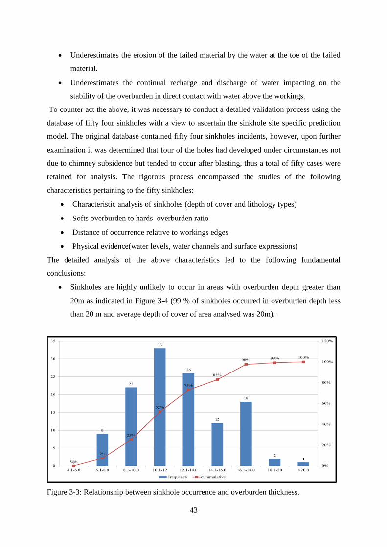
Sinkholes are highly unlikely to occur in areas with overburden depth greater than
20m as indicated in Figure 3-4 (99 % of sinkholes occurred in overburden depth less
than 20 m and average depth of cover of area analysed was 20m).
Figure 3-3: Relationship between sinkhole occurrence and overburden thickness.

44
The chances of sinkholes occurring in overburden comprised of a beam of greater
than 5m hard overburden is quite remote as indicated in Figure 3-5 (90% of sinkholes
occurred in hards composition in the overburden less than 5 m and the average
thickness of hards in analysed area was 7m). Sinkholes occurring in areas with more
than 5 m hards material in the overburden occur after blasting and manifest during the
overburden removal by the dragline. These are a direct result of the weight of the
machinery which impact on areas that are not fully collapsed during blasting.
Figure 3-4: Relationship between sinkhole occurrence and thickness of the hards in the
overburden overlying the coal seam.
Sinkholes are unlikely to form in areas with parting thickness between the mined and
unmined seams being greater than 1 m as indicated in Figure 3-5 and Figure 3-6 (81
% of sinkholes occurred in undermined areas with parting between the two seams less
than 1m). Most sinkholes that occur in areas greater than 1 m parting thickness
primarily occur after blasting under the weight of the dragline or during drilling under
the weight of the drill rig especially in areas affected by spontaneous combustion as
opposed to the classical progressive sinkhole formation.

45
Figure 3-5: Relationship between sinkhole occurrence and thickness of the parting lying
between the mined No.1 and unmined No.2 seam horizons.
Figure 3-6: Picture indicating the relationship between sinkholes occurrence and thickness of
parting between mined and unmined seam horizons.
There was no correlation between the sinkhole occurrence and thickness of the
unmined seam overlying the previously mine one as indicated inFigure 3-7, although
a thin unmined seam could be indicative of the weathered unmined seam, thus
implying compromised hards beam in the overburden.

46
Figure 3-7: Picture indicating the sinkhole traversing through a thick unmined seam overlying
a thin parting and mined No.1 seam.
98 % of sinkholes occurred in areas with overburden material comprised of soft
overburden material less than 18 m as indicated inFigure 3-8. This correlates well
with the world figure of 15 m which Hunt (1980) defined as the most sinkhole
occurring predominant depth. This indicates that there is a higher propensity of
sinkholes to occur in areas with overburden cover comprised of weathered material.

47
Figure 3-8: Shows the relationship between the softs overburden thickness and sinkhole
occurrences.
Most sinkholes were found in areas within proximity of the seam outcrops as depicted
in Figure 3-9 thus indicating a higher propensity of sinkholes to form in near
subsurface areas.
Figure 3-9: shows the predominant occurrence of sinkholes within the outcrop zones of the
orebody as indicated by black dots.

48
Field inspections and composition analysis indicated the following
Sinkholes were also found to occur in areas amenable to water accumulation (water
collection points exposed to continual recharge and discharge, thus leading to
chemical weathering as well as the washing away of the toe of the failed material).
Sinkholes are likely to form in areas comprised of weak formation such as shales
which are quick to degrade under water as opposed to areas overlain by sandstone and
grit.
3.2.3 “Adopted Sinkhole Hazard identification Process”
The detailed studies of the field sinkhole database led to the adoption of the two tier approach
to sinkhole hazard identification:
3.2.3.1 Tier 1 risk assessment
This process is a desktop study that predicts the potential for sinkholes to occur in a certain
area based on the geological model for mining blocks measuring 100m by 60m, thus
facilitating the division of the areas into high and low hazard zones as indicated by the flow
diagram in Figure 3-10.
Figure 3-10: Flow diagram indicating the desktop Tier 1 process.

49
Tier 1 risk assessment process differentiates between high and low risk areas culminating in
the production of a generic sinkhole plan as indicated in Figure 3-11.
Figure 3-11: Generic sinkhole hazard plan based on Tier 1 process.
Tier 1 process also takes into account the following:
Thickness of parting overlaying the old workings
Thickness of hard material above the old underground workings
The total overburden thickness
The caving height (formation of a “chimney”) as a function of the height of the old
workings, bord width, angle of repose of the material and the swell factor.
3.2.3.2 Tier 2 risk assessment
Tier 2 risk assessment is conducted to confirm the results of the tier 1 (desktop study). This
risk assessment process is undertaken by a multidisciplinary team comprised of mine
planning, rock engineering, survey and mine production. Prior to the commencement of
mining in a block measuring 100m by 60m and is called a strip, a full mining strip assessment
will be carried out. This strip assessment will include a hazard identification, risk assessment
and operational considerations.

50
The hazard identification and risk assessment will focus on the development of sinkholes and
other geotechnical and mining hazards (highwall stability, spontaneous combustion, lowwall
stability, activity interaction as well as mobile machinery). The following process takes place:
All red and green blocks are subjected to this assessment
Red remains red and can never turn green
Green areas can be turned into red.
Tier 2 risk assessment process cognisance of the physical evidence from:
Cloth plans
Borehole logs
Aerial photographs
Field inspection
The above approach led to the Hill (1996) caving height approach being discounted to assess
the propensity of sinkhole formation. The tier 1 approach is a desktop study that interrogates
the probability of sinkhole formation based on the geology model subjected and now a
function of the following revised criteria:
Area is considered low risk on per block by block basis if:
• Parting between Mined No 1 seam and unmined No 2 seam (P1) >1 m
• Hards in OVB > 5 m
• OVB > 20 m
• Old underground workings are not present
• Anglo American Coal Hazard Index (AMcoal HI) is less than 7.
In sub outcrop areas only 1 condition should be satisfied:
• OVB > 20m
This led to the classification of mining blocks into two risk categories as opposed to the
original three as follows as indicated in Figure 3-12.

51
Low risk areas are colour coded “Green”
High risk areas are colour coded “Red”
Figure 3-12: Plan the desktop “Sinkhole Prediction Model” for mining blocks measuring
100m by 60m in the mining window under the refined Model.
3.2.4 Shortcomings of the Adopted sinkhole hazard identification process (“SHIP”)
Following the adoption of the two pronged approach to sinkhole hazard identification the
residual risk of sinkholes culminated in two sinkhole incidences as indicated in Figure 3-13
and Figure 3-14.

52
Figure 3-13: The dragline stuck in the residual sinkhole as indicated in the above picture.
Figure 3-14: Sinkhole occurrence in block lying in juxtaposition to blasted ground (linked to
blast vibrations and weak lithology in the overburden).
The residual sinkholes were primarily occurring in the following areas:

53
Ground shaking due to blast vibrations led to increased occurrence of cavity
formation risk on rehabilitated ground (roughened up) as well as levelled areas
inclusive of drill benches and dragline walkways.
Weak lithology in the overburden (roughened up areas) – areas comprised of shales
which are amenable to undergo further degradation when exposed to vibrations (due
to blasting and equipment as well as machinery weight) and water (chemical change
of shales to clay, as well as repeated contraction and expansion), thus leading to
elevated cavity formation.
The gap created by the above two occurrences led to the need to further refine the sinkhole
management tool to facilitate minimal production stoppages as well as eliminate residual
sinkhole incidences in the operation.
This led to the introduction of a detailed analysis of borehole logs to assess the presence of
weak strata in the overburden (which contribute at least 99 % of sinkholes as indicated in
Figure 3-15) that has greater influence to sinkhole occurrence.
Lithological analysis as indicated in Figure 3-15 and Figure 3-16 was undertaken and
this led to the development of an additional criteria for managing areas comprised of
weak overburden material, which culminated in the if (and condition) being adopted.
An area will be classified as “Deep Red Area” if the following conditions are met:
Total OVB < 15m and
Thickness of hards in OVB < 1m
This led to a revised hazard plan for sinkhole management. An example to one of the revised
plans is provided in Figure 3-17. The abbreviations in Figure 3-15 are defined as follows:
TOPO- refers to a topographical surface.
BHSO refers to base horizon of soft overburden material
BHWE refers to base horizon of weathered material
TOC refers to top of coal
BOC refers to bottom of coal

54
Figure 3-15: Plan view indicating the areas subjected to lithological analysis based on
borehole logs.
Weak overburden material refers to material that can be mechanically excavated by a shovel
or dragline without having been blasted as indicated in Figure 3-16.
Figure 3-16: Down sinkhole section indicating the weak overburden material above the coal
seam.

55
This led to the development of “Deep Red Areas “(Red #) classification as indicated in
Figure 3-17.
Figure 3-17: Plan indicating refined Adopted “Sinkhole Prediction Model” incorporating
Red # (Deep Red Areas) in areas associated with weak lithology.
3.2.4.1 Refined “Adopted Sinkhole hazard Identification Process”
The refined model was adopted as the credible sinkhole prone area identification and is
indicated in Figure 3-17. This is a desktop study which is an outcome of the Tier 1 and 2
approaches to risk identification. This is further augmented by the Tier 2B process which is a
detailed reconciliation process that ensures both the chimney (geometry related) and any
residual sinkholes (blasting induced) are fully eliminated thus leading to safe mining
execution within a given mining block. This system is quite robust and has managed to offer
a methodology which for now can be described as “Full Proof” and is capable of identifying
the sinkhole risk prone areas.
3.3 Summary
This chapter discussed the problem of how to predict the areas with sinkhole risk. The
problem was resolved by using an automated sinkhole prediction method (tier 1) in
conjunction with physical evidence of the conditions around the area to be mined (tier 2).

56
The chapter discusses the various enhancements to the “Sinkhole Prediction Model with the
aim of producing a robust system of ensuring coal extraction optimisation without exposing
equipment and personnel to unsafe conditions. The next chapter discusses the primary
sinkhole rehabilitation process and the refinements to enhance coal extraction safely.

57
4 SINKHOLE MANAGEMENT PROCESS
4.1 Access control
Once an area has been identified as having potential for sinkhole formation (Tier 1 process)
and confirmed by the Tier 2 process, the area should be marked by “Red” and “Green”
boards placed in conspicuous places for high and low risk areas respectively, for the purpose
of access control as indicated in Figure 4-1 and Figure 4-2. This is done to safeguard both
personnel and equipment. Areas with sinkhole potential are not accessed with people on foot
during day and night shift. Only equipment with provision of adequate plant lighting are used
in areas with sinkhole risk at night.
Figure 4-1: Access controls for High risk areas (Red # and Red).

58
Figure 4-2: Access controls associated with Green areas (Low risk).
4.2 Rationale of the roughening up process
Currently this work is contracted to a company called “BBT” who are specialists in sinkhole
stabilisation. The contractor is required to firstly strip and reclaim topsoil to the required
depth within the equipment reach from a stable area as indicated in Figure 4-3. The topsoil is
to be ‘live’ (live placement refers to the digging of the topsoil and immediately takes it to the
place to be rehabilitated without stockpiling it) placed dependant on placing area availability
or stockpile in areas identified by the mine. Reclaiming of topsoil is essential to prevent loss
of topsoil in the roughening up process required to stabilise the hazardous areas. On average
50 000m3 of topsoil is planned to be stripped per month depending on mining areas and
conditions. The stabilisation of hazardous red areas requires excavation from a stabilised area
down to a depth of 5-6m within equipment reach.

59
Figure 4-3: Top soil reclamation in areas to be roughened up (High risk).
Roughening up is a method that is used to make the area prone to sinkhole formation safe
prior to conducting activities. The digging depth is limited to a maximum depth of 6m.
The roughening up process which is a method used to stabilise areas amenable to sinkhole
formation during either top soil removal or overburden drilling as detailed in the following
section.
Prior to roughening up the following process is followed:
A roughening up plan is generated for each area (block measuring 100m by 60m).
This plan is accompanied by a cross section indicating the anticipated digging
depth (4-6m) or until intersection of a competent beam whichever comes first
from a stationary position.
The underground workings in the planned roughening up area are pre-loaded onto
a global positioning System (GPS) to guide the surveyor to travel and walk in a
safe area free of potential void collapses.
The surveyor demarcates the starting position for the roughening up at least 30m
away from the edge of the underground workings for the block to be stabilised as
indicated in Figure 4-4. The roughening up machine will commence the

60
stabilisation of the sinkhole prone block from a known stable ground as indicated
in Figure 4-4. The underground edges are known from the survey plan of the
previously mined workings.
Figure 4-4: The roughening up starting position 30m away from the edge of the known
underground workings (High risk areas).
The stabilising process always commences from a known stable ground 30m
away from the edge of underground workings as indicated in Figure 4-4, thus
ensuring guaranteed safety of personnel and equipment.
Excavator positions the bucket as indicated in Figure 4-4 on the marked starting
point and commences digging towards the high risk zone. The digging process
takes place for at least the boom length advance whilst excavator is in one
stationary position as indicated in Figure 4-5.

61
Figure 4-5: The Sinkhole exposure process
Excavator also strips the topsoil that is within the reach of boom and places it
onto the tipper positioned behind the excavator on stable ground, thus facilitating
recovery of topsoil in high risk areas.
After the topsoil removal the subsoil / weathered material inclusive of any other
mechanically free removable material are placed on the sides of the area to be
stabilised. If required, excess material will be loaded away with another excavator
and trucked away.
The machine then digs to a maximum depth of 4-6m based on machine reach or
until a hards material beam has been intersected. The machine then presses the
bucket on the exposed beam to ascertain the competence of the intersected
maximum digging depth or beam. This process of imparting force on the exposed
beam is called “probing”.

62
After probing and ascertain the horizon competence the side stacked material is
filled back to cover the created void as indicated in Figure 4-6.
Figure 4-6: The backfilling of the created void in high risk areas by Dozers.
The excavated area is then backfilled with a dozer as indicated in Figure 4-6 and
compacted by the roller as indicated in Figure 4-7 before moving forward to the
next area for stabilisation, thereby ensuring people and equipment are always on
stable ground.

63
Figure 4-7: The compaction of the backfilled void by the roller in high risk areas.
Once the void in front of the Excavator is filled and compacted, the Excavator
must slowly advance forward half of the boom length as indicated in Figure 4-8.
Figure 4-8: Excavator forward movement after stabilisation of dug void (High risk areas).

64
If at any point the topsoil stripping or stabilising of potential sinkhole area
becomes unsafe due to cavity manifestation the work will be stopped and the area
barricade off. The area will be reported to management upon which an inspection
will be conducted prior to commencement of the roughening up process.
The above process is repeated until the entire block has been stabilised.
Any sinkholes identified during the roughening up process are reported and are surveyed and
the database will be updated accordingly. The sinkhole will be analysed to ascertain the
correlation between the sinkhole characteristics against the criteria of overburden thickness,
hards composition, softs to hards ratio and parting thickness. This is done to check the
integrity of the set criterion of sinkhole prediction.
4.2.1 Roughening up Quality
The roughening up quality is aimed at ascertaining if work has done by the contactors to the
required specifications. The detailed check of the contractor quality work execution is as
follows:
Roughening up quality inspections are conducted twice per week by the strata
control officer and the Assistant pit superintendent.
The digging up depth is compared to the planned digging depth as provided on
the cross section. This serves as a reconciliation process thus ensuring the
guaranteed credibility and quality of the roughening up process.
Where planned digging depth do not match the sections the information is fed
back to adjust the geology model and new cross sections generated to inform the
future roughening up in the forward blocks in the direction of mining.
4.3 Limitations of sinkhole management
Following the implementation of the sinkhole management the following challenges were
realised.
Occurrence of sinkholes in roughened up areas ahead of the blasted benches.
Occurrence of residual sinkholes in blasted areas.

65
Roughening up of entire mining block measuring 100 m by 60 m is time consuming
(targeted roughening up not feasible due non availability of equipment to locate exact
location of the actual void).
Roughening up of a 100 m by 60 m mining block is costly and is equivalent to the
cost of rehabilitating one sinkhole and is approximately R3.5 million, which translates
to R7/sales tonne.
In order to curtail the challenges alluded to above the following rigorous refinements as
discussed in section 4.4 had to be undertaken.
4.4 Enhancements to sinkhole management
4.4.1 Minimisation of Sinkholes in treated areas (adjacent to blasted benches).
To address the pitfalls of the roughening up process the following robust controls were then
initiated:
Stringent controls were implemented to ensure consistence in the quality of work undertaken
by the contractor includes reporting and recording of any identified abnormalities picked up
during roughening. This led to the further affirmation of a robust self-auditable system aimed
at enhancing the quality and quantification of the roughening up process. Areas that would
have gone beyond two months as indicated in Figure 4-9 before blasting had to be re-assessed
and roughened up if necessary. This was to cater for any potential cavities that would have
progressed due to blast vibrations from the adjacent blocks.
Figure 4-9: Trigger plan indicating the lag time lag between roughening up and blasting.

66
4.4.2 Blasted areas “Residual sinkhole elimination”
In order to ensure total elimination of sinkholes in blasted areas the following robust method
was introduced to ensure complete collapse of the voids, thus eliminating the occurrence of
residual sinkholes (occurrence of sinkholes in blasted areas):
Drill and blast reconciliation process as indicated in Figure 4-10 was introduced to ensure the
success rate of the drill and blast process. This was aimed at ensuring drilling and blasting
accuracy, thus ensuring total void collapse in all blasted benches. The success rate of this
process is a function of the accurate position of the pillar in the given mining layout.
Figure 4-10: Schematic sketch indicating the reconciliation process between drilling and
blasting to ensure total void filling.
4.4.3 Precise sinkhole identification
A rigorous risk assessment programme aimed at evaluating the extent and impact of
sinkholes or subsurface cavities was undertaken, with a view to developing a comprehensive
sinkhole identification and elimination method to the risk posed by these sinkholes.
An asset optimization project was commissioned in early 2012 to develop a technique for the
autonomous detection of voids within the first 20m of ground surface. Several geophysical
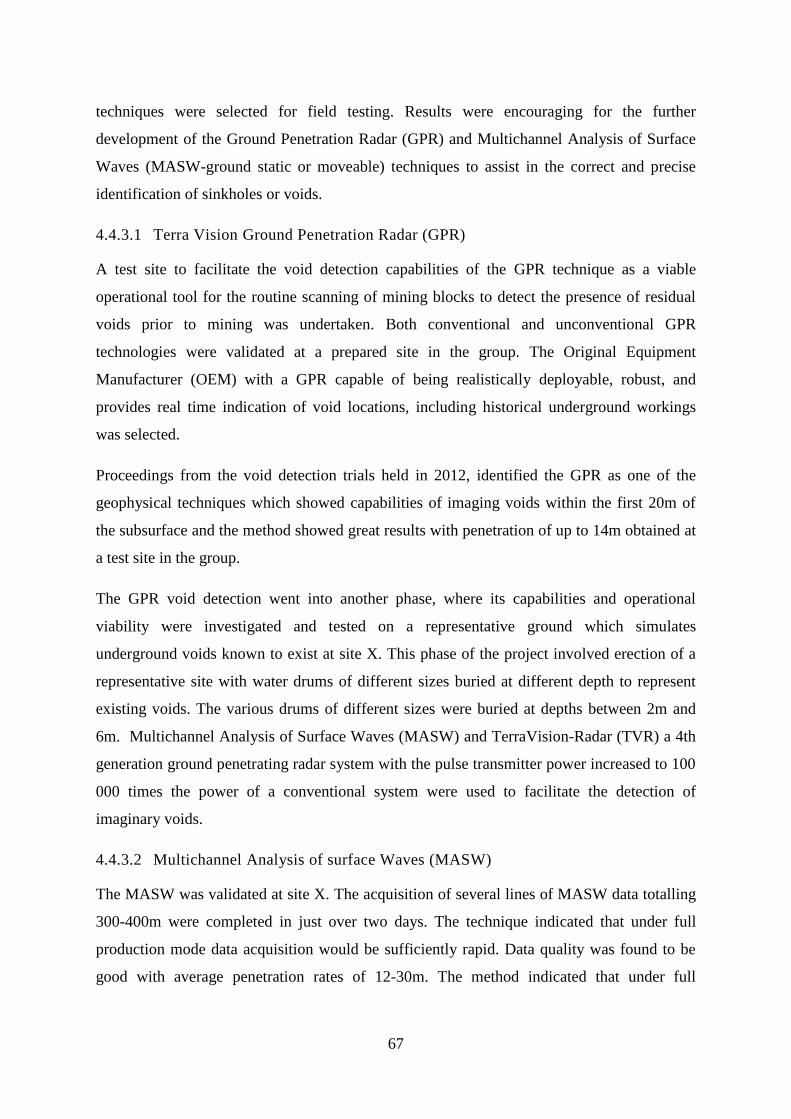
67
techniques were selected for field testing. Results were encouraging for the further
development of the Ground Penetration Radar (GPR) and Multichannel Analysis of Surface
Waves (MASW-ground static or moveable) techniques to assist in the correct and precise
identification of sinkholes or voids.
4.4.3.1 Terra Vision Ground Penetration Radar (GPR)
A test site to facilitate the void detection capabilities of the GPR technique as a viable
operational tool for the routine scanning of mining blocks to detect the presence of residual
voids prior to mining was undertaken. Both conventional and unconventional GPR
technologies were validated at a prepared site in the group. The Original Equipment
Manufacturer (OEM) with a GPR capable of being realistically deployable, robust, and
provides real time indication of void locations, including historical underground workings
was selected.
Proceedings from the void detection trials held in 2012, identified the GPR as one of the
geophysical techniques which showed capabilities of imaging voids within the first 20m of
the subsurface and the method showed great results with penetration of up to 14m obtained at
a test site in the group.
The GPR void detection went into another phase, where its capabilities and operational
viability were investigated and tested on a representative ground which simulates
underground voids known to exist at site X. This phase of the project involved erection of a
representative site with water drums of different sizes buried at different depth to represent
existing voids. The various drums of different sizes were buried at depths between 2m and
6m. Multichannel Analysis of Surface Waves (MASW) and TerraVision-Radar (TVR) a 4th
generation ground penetrating radar system with the pulse transmitter power increased to 100
000 times the power of a conventional system were used to facilitate the detection of
imaginary voids.
4.4.3.2 Multichannel Analysis of surface Waves (MASW)
The MASW was validated at site X. The acquisition of several lines of MASW data totalling
300-400m were completed in just over two days. The technique indicated that under full
production mode data acquisition would be sufficiently rapid. Data quality was found to be
good with average penetration rates of 12-30m. The method indicated that under full

68
production mode data acquisition will be sufficiently rapid thus allowing for timeous decision
making by management. This will ensure non production delays, thus enhancing productivity.
4.4.4 Results
The results indicated that the GPR was the preferred tool for deployment compared to the
MASW due to the following reasons:
GPR is cheap, readily accessible and deployable in an autonomous mode.
Relatively little processing time compared to other geophysical survey techniques
Data processing is rapid with potential for overnight processing with positional
accuracy supported if system is fitted with a Differential Global Positioning to
enhance data quality (more accurate location of the anomalous responses in real time).
4.4.4.1 Weaknesses of void detection system (GPR)
During the test work at site X and Y the GPR system as indicated in Figure 4-11 was set to
assist in identifying the buried “Jojo ”tanks (representing underground voids or sinkholes at
depth) at variable depth. The GPR was deployed in a selected block as indicated in Figure
4-12.
Figure 4-11: GPR system deployed in the field to detect buried tanks at variable depth.
During the test work the following flaws were identified:

69
The anomalous point picked by the GPR did not correlate with the georeferenced
buried “Jojo “tanks position
In areas with geological anomalies such as faults, the GPR picked these as buried
tanks, thus indicating the system’s inability to distinguish between geological
anomalies and voids due to underground workings.
Penetration rates of a low as 1-3 m metres were recorded for areas overlain by
conductive layer such as shales and wet rock formations. This indicated the limited
application of the system in areas overlain by wet and conductive rock formations.
Not practical to deploy routinely in closely spaced lines (less than 1.5m) to facilitate
detection of the smallest possible void.
Figure 4-12: Selected test block (Yellow) where tanks were buried (Pink text).
4.4.5 Cost reduction
The need to reduce the cost of rehabilitating sinkholes still remains a challenge. This could
not be mitigated since the autonomous void detection systems pursued could not assist in
precisely and accurately pinpointing the actual sinkhole position to inform point
rehabilitation thus saving cost of digging and backfilling the entire 100m by 60m block.

70
4.5 Summary
This chapter discussed the sinkhole management process in this research report by giving
some of the pertinent issues regarding the rationale of the sinkhole stabilisation process
including the pitfalls and refinements that were undertaken to ensure robustness in the system
which is meant to mitigate the loss of life and equipment. The inadequacy of the trialled void
detection system was also discussed. The void detection was aimed at assisting in the exact
location of the void or sinkhole with a view to guide targeted roughening. Targeted
roughening up would mean only digging and stabilising the void in the exact location as
opposed to digging an entire block measuring 100m by 60m,thus leading to reduced
roughening up costs. The next chapter concludes the research and recommendations to ensure
sustainability.

71
5 CONCLUSION
5.1 Chapter overview
There is need to develop a sinkhole risk mitigation process that is robust and sustainable. The
current status is that the implemented process has managed to eliminate the incidence of
sinkholes and equipment damage but still incurs a huge cost to the company. This
observation was corroborated by the failure to implement an autonomous void detection
system that can enable the treatment of a void at a point within a spatial block measuring
100m by 60m. This will lead to reduced roughening up costs as the process will be targeted at
a specific point that is amenable to collapsing impacting on activities above the void horizon.
The aim of this research was to develop a robust method of identifying the potential zones in
which sinkholes are likely to form as well as develop a method for treating these voids thus
mitigating the loss of life and equipment. This research has managed to largely achieve this
aspect in addressing this major milestone. The research report sort to develop a system to
facilitate safe coaling in previously underground mined workings with a view to manage the
sinkholes within Anglo Coal operations.
5.2 Contribution
The methodology for sinkhole prediction is primarily underpinned by the following three
parameters:
The thickness of depth of overburden cover, composition of hards in the overburden
and thickness of parting (separating the mined and unmined seam horizons)
The methodology was empirically developed and later affirmed by back analysis of the actual
sinkhole incidences (over 100 sinkholes to date).
These parameters were identified to correlate well with development of sinkholes and now
form the main criteria in the development of the sinkhole hazard plan. There is a need to
augment the locked in parameters with the following process:

72
An analysis of the lithology will assist in zonal division of areas based on rock
formations that have an elevated sinkhole formation potential.
Implementation of a robust roughening up quality audit is crucial to the success of the
sinkhole treatment.
Drilling and blasting accuracy aimed at completely collapsing the underground
workings would lead to total elimination of residual collapses on blasted benches
(which is a function of the correct identification of the positions of the underground
workings).
Timing between roughening up and blasting is of prime importance as the sinkholes
are likely to reoccur in previously rough up areas, primarily due to ground
deterioration arising from blast vibrations of adjacent blocks.
There seems also to be merit in pursuing automated mining though this exposes
equipment (equipment damage due to falling in voids or sinkholes) and personnel
(falling into voids during equipment retrieval process).
The way forward, in the absence of a well-known and scientifically proven precise sinkhole
prediction model is to make use of the following
Critique of the prediction process
Implement stringent controls on accurate drilling and blasting
Implore roughening up to yield desired results.
Understanding the influence of the time lag between roughening up and blasting to
sinkholes occurrence.
Sinkhole prediction process should be developed based on site specific data in order to
produce a robust tool for sinkhole management. The theoretical basis should form the initial
backbone of the prediction model and this should be subsequently refined to align the
prediction to actual sinkhole occurrence. The analysis of sinkholes after exposure and
establishment of a database cannot be over emphasised. This in itself reflects a new way of
seeking answers to sinkhole challenge thus leading to the development of a sustainable
system to manage sinkholes. In the past, mines used to depend on the caving height formula
as first discussed by Hill (1996) which was based on geometrical considerations. Geometrical
considerations are variable and site specific and are thus not robust enough to cater for

73
variability in mining environment dynamics. This research report recognised the diverse
changes in conditions and ground response in areas lying in juxtaposition thus indicating the
need to zone areas to assist in better management of the hazards. Having a database that is
capable of capturing information from the entire population coupled with the potential to be
updated over time presents a powerful tool to deal with sinkhole management. This research
has also managed to set the scene by indicating the limited application of the GPR system as
a void detection tool in conductive and wet rock formations including geological anomalies.
5.3 Limitations and constraints of the project report
Although this research report has achieved its aim, there are some limitations and constraints
which need to be considered. These are:
Inability to precisely identify the actual void location to facilitate location specific
treatment, thus reducing rehabilitation cost (TerraVision could not yield meaningful
results).
Reliability of data (ability to distinguish between naturally forming voids and blast
related ones).
Understanding of sinkhole formation dynamics and ground response.
5.3.1 Lack of precise void identification
The roughening up process is a costly exercise as it involves searching for voids in the entire
mining block measuring 100 m by 60 m. This is associated with high costs and there is need
to invest in precise void detection methods to guide roughening up of problematic zones
within the mining block. There seems to be merit in initiating serious research work in order
to fully understand the sinkhole formation dynamics. This will assist in giving insights as to
the route to take in order to accurately and precisely identify the next sinkhole position with a
view to facilitate targeted rehabilitation. Use of improved hybrid modelling techniques such
as “ELFEN” might be worthwhile.

74
5.3.2 Reliability of data
There is need to distinguishing between naturally forming and blast induced voids. This
would assist in reducing errors creeping into site specific sinkhole prediction models. There is
need to enforce detailed investigations to ascertain the root cause of the void prior to its
incorporation into the database informing the sinkhole prediction model by the rock
engineering department on each site or operation. Currently this is being hampered by
mistrust and lack of trustworthiness, thus leading to inclusion of redundant data that will lead
to skewed analysis. This will lead to errors creeping into the back analysis thus leading to
poor correlations and onerous predictions. This can be eliminated through documenting a set
of characteristics that distinguish between a naturally forming and blast induced cavities. This
should also be followed by digging up process to expose the cavity for assessment thus
leading to accurate classification. To the extent possible, the researcher verified the
information provided, resulting in certain data not being considered in the back analysis.
5.3.3 Sinkhole formation dynamics
Currently there is lack of good understanding around sinkhole formation dynamics. There is
belief that sinkholes initiate at roof level horizon is principally a direct result of tensile failure
as opposed to shear (Van Der Merwe, 1998). The failure will progress up until it intersects a
competent beam in the roof. The failed material will choke up the hole. There is however no
clear cut link between sinkhole caving height and the water washing effect. Water tends to
wash the material at the caved material toe, thus creating more room for material failure. Un-
choked areas can be exposed to the agents of weather and can further degrade thus leading to
changes in the competence of the beam leading plausible collapses. The effect of water was
taken into account in this research by assuming areas liable to water ingress might be
problematic and were thus incorporated as high risk zones. These areas are subjected to
continual recharge and discharge leading to chemical alteration and weakening of the
overlying beam.

75
5.4 Future work or recommendations
This research has established a reference point for exploring other research questions. Using
this report as a starting point work on a thesis investigating the clear understanding of
sinkhole formation dynamics as well as numerical modelling coupled with geophysical
survey methods can lead to better optimisation of the prediction model, thus leading to
reduced costs as treatment could only de conducted routinely on areas where the next
sinkhole has been predicted. Information in the database may be expanded to include the
contribution from other mining houses lying in the same geological zone and having similar
rocks types exhibiting similar characteristics. This might lead to improved correlations in
managing the sinkhole prediction across the mining boundaries of mining houses. This will
assist in better understanding of formation dynamics that can better equip mines to manage
the risk of sinkholes in Witbank. The Witbank deposit is characterised by significant
underground mining with a lot of undermined surface infrastructure. This poses a huge
challenge for mining operators to maintain these large expanses of land and also acquire
closure certificates when mining ceases in the Witbank coalfield.
The sinkhole database should be designed to link mines and areas exhibiting similar rock
characteristics. This data should be analysed to offer a plausible sinkhole risk management
solution post the Witbank deposit. Another addition which may be useful is a forum for
dialogue between different mines to assist in common understanding of the sinkhole
challenge facing the Witbank coal deposit. Currently work is being conducted at other sites in
the group to develop prediction methodologies aligned to individual sites.
5.5 Conclusion
A sinkhole prediction model with enhancements of the roughening up process, drilling and
blasting effectiveness was developed and implemented at site X and this system is being
rolled out to other Anglo American Coal operations.
5.5.1 Key summary points
Sinkhole prediction model was implemented at site X, and is function of the
overburden depth, composition of hards in the overburden inclusive of parting
thickness in the layer separating the mined seam (No.1) from the virgin (unmined
No.2 seam) one. This corroborated by tier 2 critically scrutinises the physical

76
evidence on the cloth plans as well as field information from areal flights and
exposed highwalls.
An analysis of the lithology will assist in the zonal division of areas based on rock
formations, indicating areas with elevated sinkhole risk.
Site X” should consider “Roughening up “as the primary void rehabilitation method
with routine operational deployment of the TVR (TerraVision) equipment to detect
residual shallow voids after roughing up and initial blasting.
Implementation of quality of the roughening up process is crucial to ensure robust
void treatment for sinkhole formation prone mining blocks, thus ensuring safe coal
extraction.
Drilling and blasting accuracy is crucial to eliminate residual sinkholes occurrence on
all blasted benches.
Proper timing between roughening up and blasting is crucial to prevent rework
especially in areas liable to disturbance due to blast vibrations from distant areas.
Precise identification of the voids seems to lie in the Ground Penetration Radar,
which at this point in time is significantly limited by presence of conductive material
such as clays, wet rock formations, geological anomalies and noise interference from
mining equipment.

77
6 REFERENCES
Anon. (1994) The Stability of Quarters due to Old Abandoned Workings of Nageswar
Satgram Unit of Mithapur Colliery in Satgram of Eastern Coalfields Limited,
Unpublished Project Report, Central Mining Research Institute, Dhanbad.
Berg, W.R. (1980) Subsidence due to Underground Mining in the Hanna Coalfield,
Unpublished Master's Thesis, University of Wyoming, Laramie, WY.
Blodgett S, Kuipers JR (2002) Subsidence and hydrologic environmental Impacts.
Technical report on underground hard-rock mining, Center for Science in Public
Participation, pp 36–38.
Brady, B.H.G. and E.T Brown, 2003 Rock Mechanics for Underground Mining,
George Allen and Unwin, 527p.
Brady, B.H.G. and E.T. Brown, 1993. Rock mechanics for Underground Mining, 2nd
Edition, Chapman & hall, London, 571p.
Brown, A. (1986) Land Use Recommendation to Minimize Subsidence Risk in
Superior, Wyoming, Report 1072/06 to Wyoming Department of Environmental
Quality, Midwest Mining Company, Littleton, CO.
Bruhn, R. W. and McCann, W. S, 1982 “Damage to Structures above Active
Underground Coal Mines in the Northern Appalachian Coal Field,” Proceedings of
the 1st international Conference on Stability in Underground Mining, West
Vancouver, B.C.
Bruhn, R.W., Magnuson, M.O. and Gray, R.E. (1978) Subsidence over the Mined out
Coal, ASCE Preprint 3293, American Society of Civil Engineers Spring Convention,
Pittsburgh, pp. 26-55.

78
Canbulat, I, Ryder, J.A (2002). Prediction of surface subsidence and sinkholes, re-
defining the boundaries, SANNIRE Symposium. Vereeniging, 6 September 2002.
Colaizzi, G.J. (1986) Private communication, Goodson and Associates, Inc., Denver,
CO.
Dunrud, C. R. (1984), Coal Mine Subsidence—Western United States,” in Man-
Induced Land Subsidence, Reviews in Engineering Geology, Volume 6, The
Geological Society of America, 151-194.
Dunrud, C.R. and Osterwald, F.W. (1980) Effects of Coal Mine Subsidence in the
Sheridan, Wyoming Area, US Geological Survey Professional Paper 1164, U.S. Govt.
Print. Off.,
Dyne, L.A. (1998), The Prediction and Occurrence of Chimney Subsidence in South
Pennsylvania, PhD Thesis, Virginia Polytechnic Institute and State University.
Gormely, J.T. (1986) Status and Report of Investigation, Glen Rock Subsidence
Control Project 8A, Gormley Consultants Inc., Englewood Cliffs, NJ.
Gray, R.E., Bruhn, R.W. and Turka, R.J. (1977), Study and Analysis of Surface
Subsidence Over the Mined Pittsburgh Coalbed, pp374.
Gray, R.E. and Bruhn, R.W., 1982, Subsidence above abandoned coal mines, state of
the art of ground control in longwall mining and mining subsidence. In: Proc. ASME,
Littleton, Colorado, pp 253-271.
Hill, R.W (1996) Safety and environmental risks associated with shallow bord and
pillar workings. Confidential COM elective project report. Report No: CE 9401.
Hunt, S.R. (1980) Surface Subsidence due to Coal Mining in Illinois, PhD Thesis,
University of Illinois at Urbana-Champaign, IL.

79
Kalendra, B., Singh, B., and Baharat, B. Dhar., (1997) “Sinkhole subsidence due to
mining”, Geotechnical and geological Engineering, Volume 15, pp. 327–341.
Karfakis, Mario. G (1986) “Chimney Subsidence- A Case Study, “Rock Mechanics:
Key to Energy Production, 275-281.
Klingenberg, J., (2012) Positions of historical sinkholes at Mine X.
Matheson, G.M. and Eckert-Clift, A.D. (1986) Characteristics of chimney subsidence
and sink hole development from abandoned underground coal mines along the
Colorado Front Range, Proceedings of the 2nd Workshop on Surface Subsidence due
to Underground Mining, West Virginia University, Morgantown, WV, pp. 204-214.
Misich, I, Evans, A and Odwyn, J, (1993) Subsidence Prediction and Management in
Collie (Western Australia),” Proceedings of the Conference on Mine Subsidence in
Urban and Developed Areas 1 – 10.
Obert, L. and Duvall, W.I, (1976) Rock Mechanics and the Design of Structures in
Rock, Wiley, New York.
Peng, S. S., (1978), Coal Mine Ground Control, John Wiley & Sons, Incorporated,
2nd edition, pp 491.
Peng, S. S., (1992), Surface subsidence engineering, Littleton, Colorado; Society for
Mining, Metallurgy and Exploration, pp 161.
Piggott, R.J. and Eynon, P. (1978) Ground movements arising from the presence of
shallow abandoned mine workings, In Geddes, J. D ed., Large ground movements and
structures, Conference at the University of Wales Institute of Science and
Technology, Cardiff, 1977, Proceedings: New York, John Wiley, p. 749-780.

80
Price, D. G., Malkin, A. B. and Knill, J. L. (1969), “Foundations of Multi-Story
Blocks with Special Reference to Old Mine Workings,” Journal of Engineering
Geology, 1 (4), 271-322.
Singh, M. ed., 1986, Mine Subsidence, Society of Mining Engineers, Littleton, CO,
1986. AIME. pp. 73-143.
Stingelin, R. W., Baker, E. T. and Cousin, S.B (1975) Overview of Subsidence
Potential in Pennsylvania Coal Fields,” HRB-Singer, Inc., State College, PA.
Van der Merwe, J.N (2002) Internal Consultancy report, titled “Expected post Closure
subsidence at Vierfontein Colliery”.
Van der Merwe, J.N. (1997). Investigation into the Mechanism of Pillar Failure at
Vierfontein Colliery. Confidential report to Vierfontein Colliery Ltd.
Van der Merwe, J.N. (1998b). Future Stability of Surface over Old Workings at
Vierfontein Colliery. Confidential report to Vierfontein Colliery Ltd.
Whittaker, B. N. and Reddish, D. J (1989) Subsidence: Occurrence, Prediction and
Control, Elsevier Science Publishing Company Inc., New York.
Wildanger, E. G., Mahar, J., and Nieto, A., Sinkhole-type Subsidence Over
Abandoned Coal Mines in St David, Illinois, Illinois Abandoned Mined Lands
Reclamation Council, 88 pp. (1980).


