
1
Integrity Service Excellence
IEEE - AP-S – Vancouver 2015
A Novel Type of Pattern Synthesis
Implementation using Corrugated
Apertures
September 2016
N. Herscovici (1) and Anatoliy Borrysenko (2)
(1) Sensors Directorate
Air Force Research Laboratory
Wright-Patterson AFB OH
A&E Partnership, Inc.
Belchertown, MA

2
Outline
• Previous Work
• Motivation
• Concepts
• Challenges
• Antenna Design
• Conclusions
• Future Work

3
Motivation
Antenna Pattern synthesis implementations
Amplitude and Phase Synthesis
Shaped Apertures

410/17/2016 4
Previous Work
Naftali Herscovici - The Shaped-Beam Polyrod Antenna,
IEEE Antennas and Propagation Magazine. Vol. 36, No.2. April,1994, pp.55-57.
Antenna Designer's Notebook

510/17/2016 5
Previous Work
5
Elevation Patterns Azimuth Patterns
Measured Data
Naftali Herscovici - The Shaped-Beam Polyrod Antenna,
IEEE Antennas and Propagation Magazine. Vol. 36, No.2. April,1994, pp.55-57.
Antenna Designer's Notebook

610/17/2016 66
HFSS Model
The Dielectric Rod Cosecant Antenna
WR90
Elevation Radiation Patterns
Validation of the Empirical Design

710/17/2016 7
Antenna 2D Profile Definition
Major functional parts: a. feeding section
b. parallel plate waveguide section
c. launching section
d. shaped Polyrod Antenna
e. matching tip
2D Profile View
3D View

810/17/2016 88
FEM Analysis
Radiation Pattern Shapes
w/o dielectric Polyrod With dielectric Polyrod
Frequencies: 9.5 , 10.0 and 10.5 GHz
Challenges
• Beam approaches cosecant shape, but requires more systematic work to
approach the cosecant square shape.
• Sidelobes near the axis of symmetry (ϑ=0O & ϑ=180O) are too high.

910/17/2016 99
Optimization Challenges
Use Cylindrical Symmetry (BOR)
• Many design parameters
• Assess and prioritize various parameter impacts
• Implementation limitation
• Use discrete parameters for optimization
• Large Computational Volume

1010/17/2016 10
Case Study – Cylindrical Short Backfire Antenna
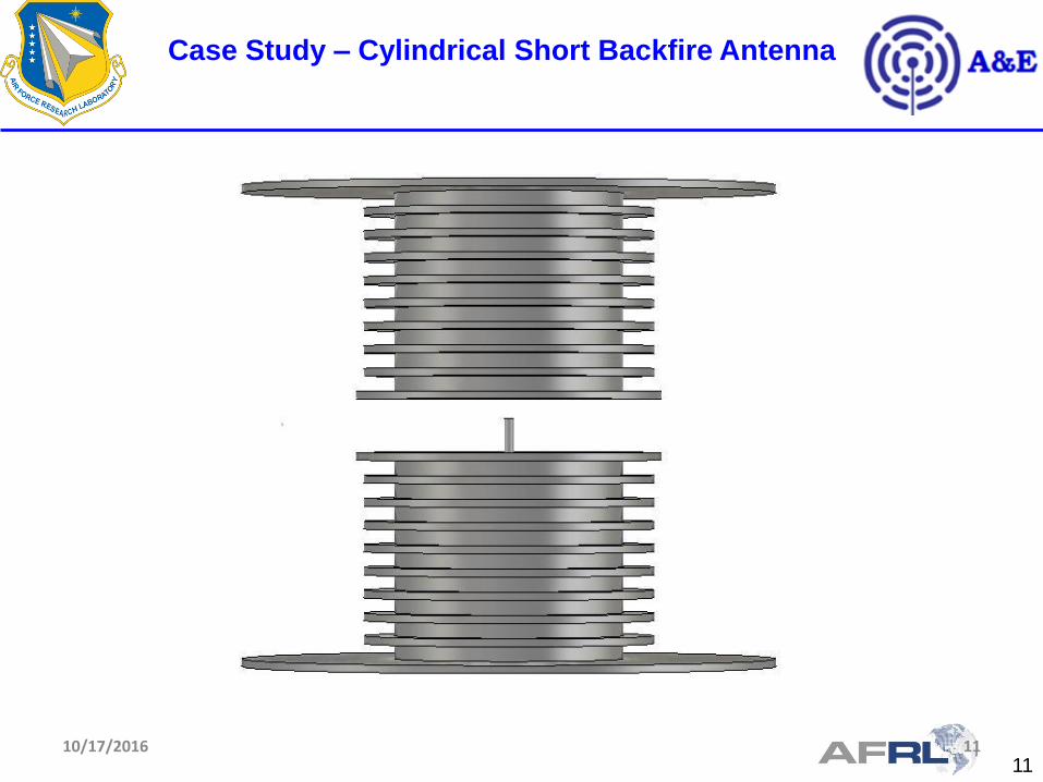
1110/17/2016 11
Case Study – Cylindrical Short Backfire Antenna
12
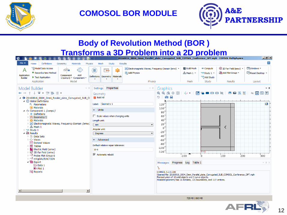
COMOSOL BOR MODULE
Body of Revolution Method (BOR )
Transforms a 3D Problem into a 2D problem
13
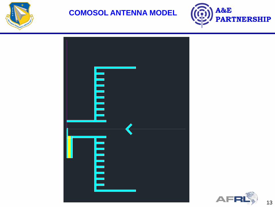
COMOSOL ANTENNA MODEL

14
FEM,TD & BOR - COMPARISON
-25.
-20.
-15.
-10.
-5.
0.
5.
10.
-180. -150. -120. -90. -60. -30. 0. 30. 60. 90. 120. 150. 180.
Gai
n[d
B]
Angle[deg]
3D FEM,TD vs BOR - 14.4GHzFEM BOR TD

15
FEM,TD & BOR - COMPARISON
-25.
-20.
-15.
-10.
-5.
0.
5.
10.
-180. -150. -120. -90. -60. -30. 0. 30. 60. 90. 120. 150. 180.
Gai
n[d
B]
Angle[deg]
3D FEM,TD vs BOR - 14.9GHzFEM BOR TD
16
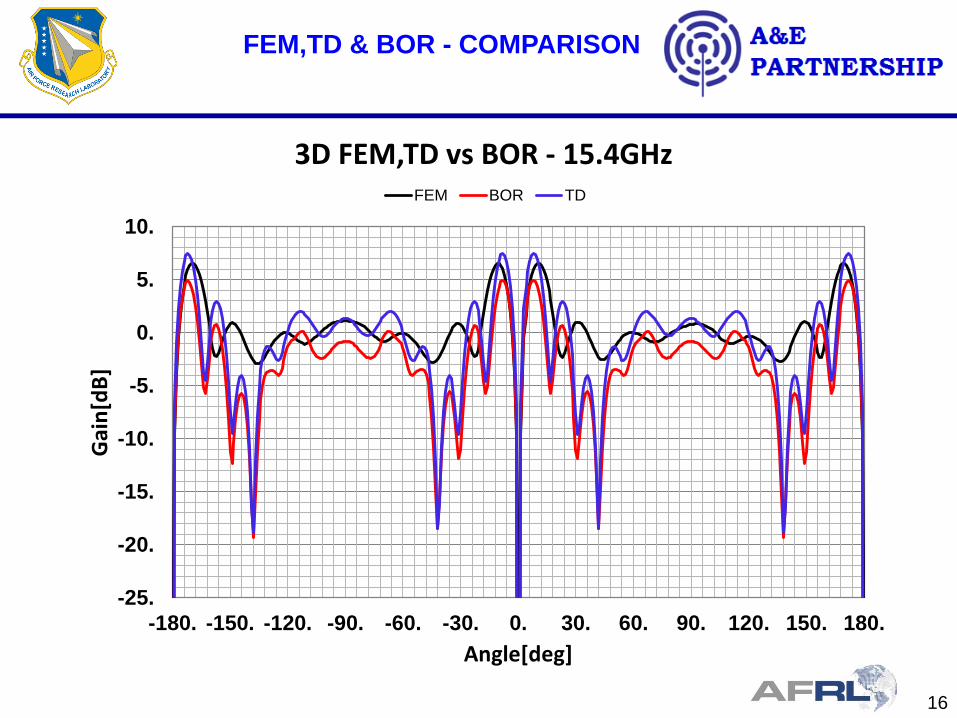
FEM,TD & BOR - COMPARISON
-25.
-20.
-15.
-10.
-5.
0.
5.
10.
-180. -150. -120. -90. -60. -30. 0. 30. 60. 90. 120. 150. 180.
Gai
n[d
B]
Angle[deg]
3D FEM,TD vs BOR - 15.4GHzFEM BOR TD
17
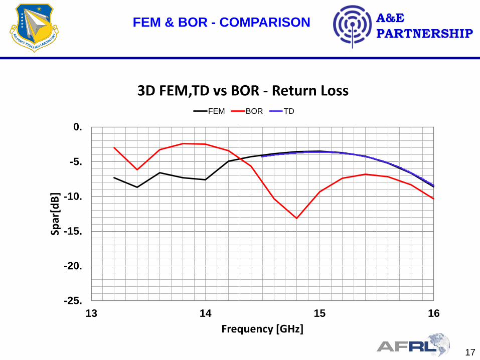
FEM & BOR - COMPARISON
-25.
-20.
-15.
-10.
-5.
0.
13 14 15 16
Spar
[dB
]
Frequency [GHz]
3D FEM,TD vs BOR - Return LossFEM BOR TD

18
Shaped Beam Cylindrical Array
COMSOL Optimized BOR Geometry

19
Shaped Beam Cylindrical Array
Optimization Results

20
Shaped Beam Cylindrical Array
Comparison between the initial geometry and the
optimized results
Shaped Beam Cylindrical Array
Improved gain and sidelobe level

21
Conclusions
• Optimization the performance of shaped
beam antennas using COMSOL BOR
module was performed.
• The optimization results produced an
antenna with higher beam efficiency
(Higher Gain and lower sidelobes)
• The corrugated ridges were proved to be
an efficient tool for pattern shaping.
• The COMSOL BOR module was validated
to be an appropriate method to be used in
the optimization process.

22
Future Work
• Optimize the performance of shaped beam
antennas using COMSOL BOR for Cosec2
pattern in elevation.
• Investigate possibility for broadband behavior.


