Download - A concept of laser scanner designed to realize 3D obstacle avoidance for a fixed-wing UAV

Roboticahttp://journals.cambridge.org/ROB
Additional services for Robotica:
Email alerts: Click hereSubscriptions: Click hereCommercial reprints: Click hereTerms of use : Click here
A concept of laser scanner designed to realize 3D obstacle avoidance fora xed-wing UAV
Cezary Kownacki
Robotica / FirstView Article / July 2014, pp 1 - 15DOI: 10.1017/S0263574714001404, Published online: 09 June 2014
Link to this article: http://journals.cambridge.org/abstract_S0263574714001404
How to cite this article:Cezary Kownacki A concept of laser scanner designed to realize 3D obstacle avoidance for a xed-wing UAV . Robotica,Available on CJO 2014 doi:10.1017/S0263574714001404
Request Permissions : Click here
Downloaded from http://journals.cambridge.org/ROB, IP address: 130.217.227.3 on 07 Jul 2014
http://journals.cambridge.org Downloaded: 07 Jul 2014 IP address: 130.217.227.3
Robotica: page 1 of 15. © Cambridge University Press 2014doi:10.1017/S0263574714001404
A concept of laser scanner designed to realize 3Dobstacle avoidance for a fixed-wing UAVCezary Kownacki∗
Faculty of Mechanical Engineering, Bialystok University of Technology, ul. Wiejska 45C, 15-351Bialystok, Poland
(Accepted May 2, 2014)
SUMMARYThis paper presents a concept of a laser scanner framework designed for obstacle avoidance used onmini fixed-wing unmanned aerial vehicles (UAVs) flying in outdoor environments. The innovationis a conical field of view that guarantees tri-dimensional (3D) obstacle detection and localizationat any pitch or roll angle. This advantage is very important for the case of fixed-wing UAV flightswhere the attitude is changing rapidly. Measurement sequences create a map that is represented by acircular grid with the center fitted to the x-axis of the UAV’s body, lying in the plane normal to thevelocity vector and projected in the front of UAV. This means that the map cells contain differencesbetween the safety zone radius and distances acquired from area in close proximity to the flightpath. Actual UAV attitude can be compensated by rotation and shift of two masks of gains thatare applied to the map to determine pitch and roll commands. Results of the simulation researchconducted on the designed concept are very promising, as they present a combination of lateral andvertical obstacle avoidance. Based on the experience with laser rangefinders operating on a real UAV,it can be convincingly determined that the concept of the laser scanner is able to be brought into reality.
KEYWORDS: Laser scanner; LIDAR; Unmanned aerial vehicle; Obstacle avoidance; Mapping;SLAM.
1. IntroductionAlthough researchers’ interest in the area of unmanned aerial vehicle (UAV) is still increasing,the problem of reliable and guaranteed obstacle avoidance remains unresolved thoroughly due toweaknesses and limitations of current perception systems, which are used onboard of a mini UAV.It should be underlined, that obstacle avoidance issues refer mostly to mini and micro UAVs sincetypical flight mission objectives for larger UAVs exclude them from operating at low altitudes inareas covered by natural or urban obstacles. The small size and small dynamic time constants ofvehicles, which are expected to be able to avoid obstacles autonomously, are main determinants forthe problem difficulty level. Having a limited payload, low computational resources, and a limitedpower supply is not feasible to achieve solutions adequate for all possible obstacle shapes, sizes,ambient lighting, etc. So researchers are now focusing on control algorithms that use syntheticobstacles in simulations5,9,12,19,23 or they present obstacle avoidance demonstrations with noticeablerestrictions that reduce their application to simple and special cases.8−11,15−18 These two scopes ofresearch taken together with addition of technology improvements can result in more autonomoussystems of UAVs.
Most of the examples of obstacle avoidance applications rely on vision sensors, which providesignificant amounts of information about UAV surroundings without a significant increase inpayload.8−11,15,17−19,23 Although this may sound excellent, vision sensors greatly suffer fromcomplexity of video processing algorithms, low resolution, ambient lighting, scene contrast, weatherconditions, and computational resources of onboard processors, from battery capacity. Combininga vision system with other obstacle detection techniques such as sound navigation and ranging
* Corresponding author. E-mail: [email protected]

http://journals.cambridge.org Downloaded: 07 Jul 2014 IP address: 130.217.227.3
2 Innovative concept of laser scanner for outdoor 3D obstacle avoidance
(SONAR) eliminates some of these issues, but the vehicle payload is also increased and additionallythe overall system is more complex. Therefore, vision systems typically run under specific conditions,applied to selected vehicles or exploration cases without a variety of real-world scenarios with closed-loop control enabled. Moreover, most of vision-based avoidance systems are applied to larger hovervehicles since miniature cameras fixed to a small fixed-wing UAV is still insufficient to preciselylocate objects and still requires a mechanical stabilization. An alternative to vision systems couldbe laser rangefinders. A few articles present successful usages of this type of sensors in outdoorflights;16,20 but at this time one or even two laser rangefinders do not provide enough information tocover all cases of various obstacle sizes and relative locations due to the effect of the limited fieldof view. Hence, using a laser scanner or a light detection and ranging (LIDAR) system for outdoorobstacle avoidance purpose, especially in urban environments could be a better idea. Such LIDARsystem could eliminate a majority of weaknesses of two sensors approach, and simultaneously it willmerge the same possibilities, i.e. obstacle avoidance with a feature of canyon flights.
Typically laser scanners or LIDARs with simultaneous localization and mapping (SLAM)algorithms are used for two main topics described in many articles: indoor environment mapping andoutdoor terrain/obstacle mapping.2,21 The mutual property of these two wide topics is employingvertical taking off and landing vehicles (VTOL), which are capable of flying horizontally. Itobviously guarantees undisturbed and stable orientation of the scanning plane that is required for two-dimensional/tri-dimensional (2D/3D) map creation. In cases of indoor mapping scanners horizontallyexplore an unknown environment to prepare an occupation grid and to find an optimal flight path. Adifferent approach was presented by MIT Robust Research Group. Their fixed-wing vehicle, whichwon the AUVSI contest in 2012, used LIDAR to deduce the vehicle position by matching the laserscan to an already known 3D map. Hence, it was possible to avoid obstacles in indoor missions, butthe remaining question is how such LIDAR odometry would work in uncertain environments? Also,in another work1 scan-matching was used to estimate the state of the quad-rotor; but it was computedoff-board including SLAM algorithms. Therefore, it suffered with its wireless communication range.
In outdoor missions, LIDARs operate vertically to evaluate terrain levels4 or horizontally tomap obstacles.9 In terrain mapping the amount of measurement data generally excludes onboardmap processing or it requires a PC-based computer like in ref. [9]. Otherwise a cloud of pointsrepresenting the terrain map is generated offline. This is commonly used to monitor trees growth inforests.6,7 Terrain mapping can be also applied in SLAD—Safe Landing and Area Detection, evenwith real-time onboard processing (Yamaha R-Max).3
Additional interesting work5 is about a 2D/3D outdoor obstacle avoidance method employingKelly’s grids, cubic Bezier curves, and a laser rangefinder with a pan/tilt module. To realize themethod, authors used a powerful platform based on a Yamaha R-Max equipped with a dual flightcomputer, which has a high enough performance level to compute all necessary calculations andcontrols. Nevertheless, only simulation results are presented to prove the method its effectiveness.Another work22 describes a successful application of a commercial 3D laser scanner installed into anidentical helicopter which indicates that the Yamaha R-Max helicopter is favorite testing platform.
Therefore, a challengeable case of laser scanner application would be using it for outdoor missionson real fixed-wing mini UAVs. Seemingly it would require stabilizing the gimbals, which increases thepayload, and further complicates the scanner framework, as in ref. [5]. Moreover, control algorithmsfor laser targeting are obligatory. There are some commercial 3D LIDARs (Fibertek Inc.) and flashLIDARs (SwissRanger SR 4000), but they are still too heavy for mini UAVs.22
To avoid these limitations, a concept of laser scanners for fixed-wing UAV is presented. It doesnot need gimbals to target laser beams, which results in a simplified framework, control algorithm,and data processing. This is a great advantage, which allows handling laser scanner operations easilyand directly from a small autopilot system or advanced microcontroller. In addition, algorithmsrelated with the processing of an occupancy map do not require complex and difficult computationsto determine the reactive commands applied in obstacle avoidance. This proposed concept of ascanner should provide more accurate information about vehicle surroundings, and it will be ableto track obstacles continuously and independently from actual vehicle attitude, unlike the case withtwo sensors.20 Simultaneously, its compact framework makes it available for mini UAVs. Presentedsimulation results prove that the developed concept of the laser scanner may be a well-suited sensorfor a wide variety of obstacle avoidance in outdoor scenarios, especially for flights through urbanenvironments.
http://journals.cambridge.org Downloaded: 07 Jul 2014 IP address: 130.217.227.3
Innovative concept of laser scanner for outdoor 3D obstacle avoidance 3
±1800 Tx/Rx aperture
- angle of conical field of view
Measurement circle
Drive /
Dsafe
servo
Laser beam
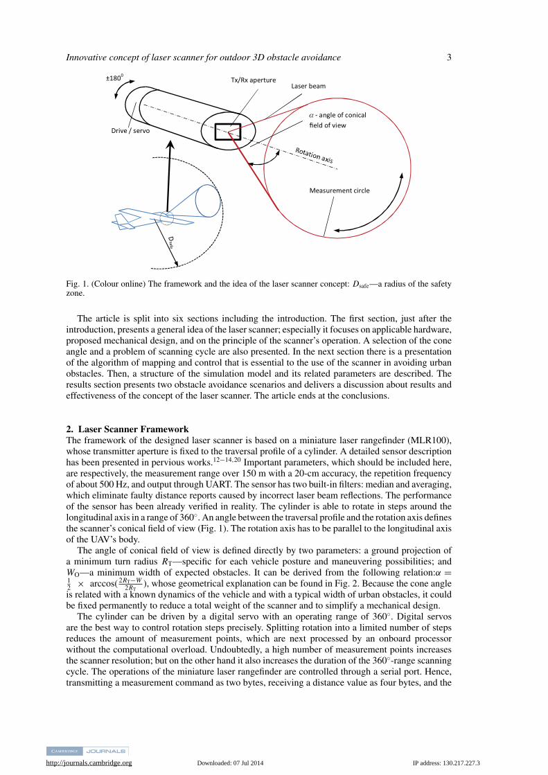
Fig. 1. (Colour online) The framework and the idea of the laser scanner concept: Dsafe—a radius of the safetyzone.
The article is split into six sections including the introduction. The first section, just after theintroduction, presents a general idea of the laser scanner; especially it focuses on applicable hardware,proposed mechanical design, and on the principle of the scanner’s operation. A selection of the coneangle and a problem of scanning cycle are also presented. In the next section there is a presentationof the algorithm of mapping and control that is essential to the use of the scanner in avoiding urbanobstacles. Then, a structure of the simulation model and its related parameters are described. Theresults section presents two obstacle avoidance scenarios and delivers a discussion about results andeffectiveness of the concept of the laser scanner. The article ends at the conclusions.
2. Laser Scanner FrameworkThe framework of the designed laser scanner is based on a miniature laser rangefinder (MLR100),whose transmitter aperture is fixed to the traversal profile of a cylinder. A detailed sensor descriptionhas been presented in pervious works.12−14,20 Important parameters, which should be included here,are respectively, the measurement range over 150 m with a 20-cm accuracy, the repetition frequencyof about 500 Hz, and output through UART. The sensor has two built-in filters: median and averaging,which eliminate faulty distance reports caused by incorrect laser beam reflections. The performanceof the sensor has been already verified in reality. The cylinder is able to rotate in steps around thelongitudinal axis in a range of 360◦. An angle between the traversal profile and the rotation axis definesthe scanner’s conical field of view (Fig. 1). The rotation axis has to be parallel to the longitudinal axisof the UAV’s body.
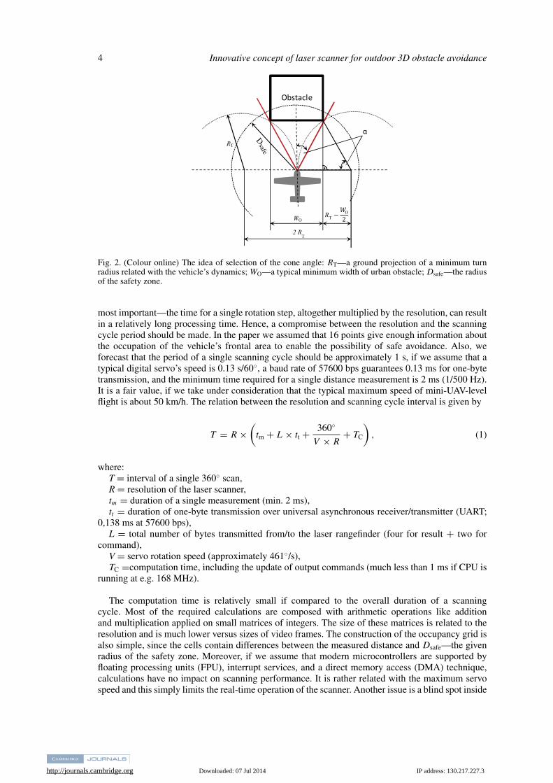
The angle of conical field of view is defined directly by two parameters: a ground projection ofa minimum turn radius RT—specific for each vehicle posture and maneuvering possibilities; andWO—a minimum width of expected obstacles. It can be derived from the following relation:α =12 × arccos( 2RT−W
2RT), whose geometrical explanation can be found in Fig. 2. Because the cone angle
is related with a known dynamics of the vehicle and with a typical width of urban obstacles, it couldbe fixed permanently to reduce a total weight of the scanner and to simplify a mechanical design.
The cylinder can be driven by a digital servo with an operating range of 360◦. Digital servosare the best way to control rotation steps precisely. Splitting rotation into a limited number of stepsreduces the amount of measurement points, which are next processed by an onboard processorwithout the computational overload. Undoubtedly, a high number of measurement points increasesthe scanner resolution; but on the other hand it also increases the duration of the 360◦-range scanningcycle. The operations of the miniature laser rangefinder are controlled through a serial port. Hence,transmitting a measurement command as two bytes, receiving a distance value as four bytes, and the
http://journals.cambridge.org Downloaded: 07 Jul 2014 IP address: 130.217.227.3
4 Innovative concept of laser scanner for outdoor 3D obstacle avoidance
Obstacle
RT
2 RT
T
α
WO
O−2
Dsafe
Fig. 2. (Colour online) The idea of selection of the cone angle: RT—a ground projection of a minimum turnradius related with the vehicle’s dynamics; WO—a typical minimum width of urban obstacle; Dsafe—the radiusof the safety zone.
most important—the time for a single rotation step, altogether multiplied by the resolution, can resultin a relatively long processing time. Hence, a compromise between the resolution and the scanningcycle period should be made. In the paper we assumed that 16 points give enough information aboutthe occupation of the vehicle’s frontal area to enable the possibility of safe avoidance. Also, weforecast that the period of a single scanning cycle should be approximately 1 s, if we assume that atypical digital servo’s speed is 0.13 s/60◦, a baud rate of 57600 bps guarantees 0.13 ms for one-bytetransmission, and the minimum time required for a single distance measurement is 2 ms (1/500 Hz).It is a fair value, if we take under consideration that the typical maximum speed of mini-UAV-levelflight is about 50 km/h. The relation between the resolution and scanning cycle interval is given by
T = R ×(
tm + L × tt + 360◦
V × R+ TC
), (1)
where:T = interval of a single 360◦ scan,R = resolution of the laser scanner,tm = duration of a single measurement (min. 2 ms),tt = duration of one-byte transmission over universal asynchronous receiver/transmitter (UART;
0,138 ms at 57600 bps),L = total number of bytes transmitted from/to the laser rangefinder (four for result + two for
command),V = servo rotation speed (approximately 461◦/s),TC =computation time, including the update of output commands (much less than 1 ms if CPU is
running at e.g. 168 MHz).
The computation time is relatively small if compared to the overall duration of a scanningcycle. Most of the required calculations are composed with arithmetic operations like additionand multiplication applied on small matrices of integers. The size of these matrices is related to theresolution and is much lower versus sizes of video frames. The construction of the occupancy grid isalso simple, since the cells contain differences between the measured distance and Dsafe—the givenradius of the safety zone. Moreover, if we assume that modern microcontrollers are supported byfloating processing units (FPU), interrupt services, and a direct memory access (DMA) technique,calculations have no impact on scanning performance. It is rather related with the maximum servospeed and this simply limits the real-time operation of the scanner. Another issue is a blind spot inside
http://journals.cambridge.org Downloaded: 07 Jul 2014 IP address: 130.217.227.3
Innovative concept of laser scanner for outdoor 3D obstacle avoidance 5
DiLaser rangefinder Average & median filters
Servo
Map update
Rotation command
Autopilot , A
DiM
Masks computations
PID
MiR
MiP
PID
WP
WR
D
D
UAV
Dsafe
∑
∑
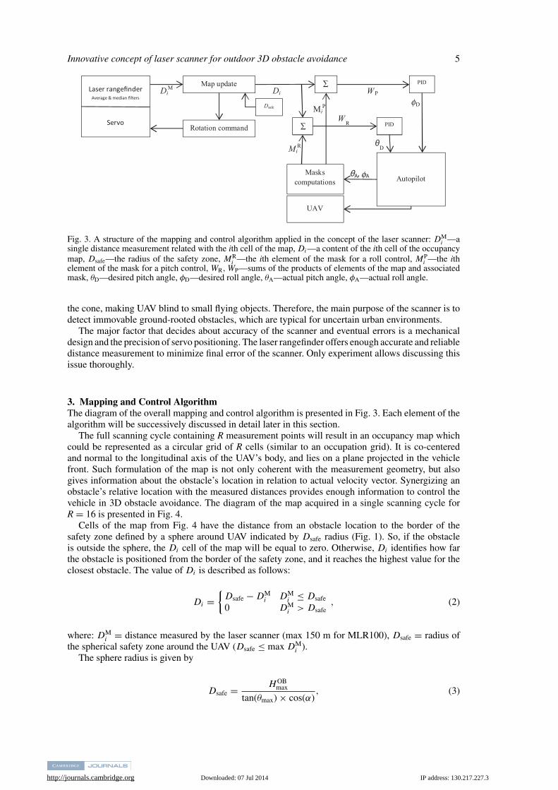
Fig. 3. A structure of the mapping and control algorithm applied in the concept of the laser scanner: DMi —a
single distance measurement related with the ith cell of the map, Di—a content of the ith cell of the occupancymap, Dsafe—the radius of the safety zone, MR
i —the ith element of the mask for a roll control, MPi —the ith
element of the mask for a pitch control, WR,WP—sums of the products of elements of the map and associatedmask, θD—desired pitch angle, φD—desired roll angle, θA—actual pitch angle, φA—actual roll angle.
the cone, making UAV blind to small flying objects. Therefore, the main purpose of the scanner is todetect immovable ground-rooted obstacles, which are typical for uncertain urban environments.
The major factor that decides about accuracy of the scanner and eventual errors is a mechanicaldesign and the precision of servo positioning. The laser rangefinder offers enough accurate and reliabledistance measurement to minimize final error of the scanner. Only experiment allows discussing thisissue thoroughly.
3. Mapping and Control AlgorithmThe diagram of the overall mapping and control algorithm is presented in Fig. 3. Each element of thealgorithm will be successively discussed in detail later in this section.
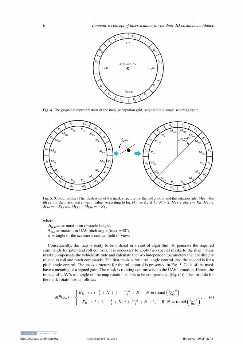
The full scanning cycle containing R measurement points will result in an occupancy map whichcould be represented as a circular grid of R cells (similar to an occupation grid). It is co-centeredand normal to the longitudinal axis of the UAV’s body, and lies on a plane projected in the vehiclefront. Such formulation of the map is not only coherent with the measurement geometry, but alsogives information about the obstacle’s location in relation to actual velocity vector. Synergizing anobstacle’s relative location with the measured distances provides enough information to control thevehicle in 3D obstacle avoidance. The diagram of the map acquired in a single scanning cycle forR = 16 is presented in Fig. 4.
Cells of the map from Fig. 4 have the distance from an obstacle location to the border of thesafety zone defined by a sphere around UAV indicated by Dsafe radius (Fig. 1). So, if the obstacleis outside the sphere, the Di cell of the map will be equal to zero. Otherwise, Di identifies how farthe obstacle is positioned from the border of the safety zone, and it reaches the highest value for theclosest obstacle. The value of Di is described as follows:
Di ={
Dsafe − DMi DM
i ≤ Dsafe
0 DMi > Dsafe
, (2)
where: DMi = distance measured by the laser scanner (max 150 m for MLR100), Dsafe = radius of
the spherical safety zone around the UAV (Dsafe ≤ max DMi ).
The sphere radius is given by
Dsafe = H OBmax
tan(θmax) × cos(α), (3)
http://journals.cambridge.org Downloaded: 07 Jul 2014 IP address: 130.217.227.3
6 Innovative concept of laser scanner for outdoor 3D obstacle avoidance
D1
D2
D3
D4
D5
D6
D7
D8
D9
D10
D11
D12D13
D14
D15
D16
Right
Down
Up
LeftX axis of UAV
Fig. 4. The graphical representation of the map (occupation grid) acquired in a single scanning cycle.
-KR
-KR
-KR -KR KR
KR
KR
KR
KR
KR
KR
KR -KR -KR
-KR
-KR
-KR
-KR
-KR -KR -KR
-KR
KR
KR
KR
KR
KR KR KR
KR
-KR
-KR
A ≅ 45
- A
MR1
MR2 MR3
MR4 MR5 MR6
MR7
MR8 MR1
MR2 MR3
MR4 MR5 MR6
MR7
MR8
MR16
MR15 MR14
MR13 MR12 MR11
MR10
MR9 MR16
MR15 MR14
MR13 MR12 MR11
MR10
MR9
φφ
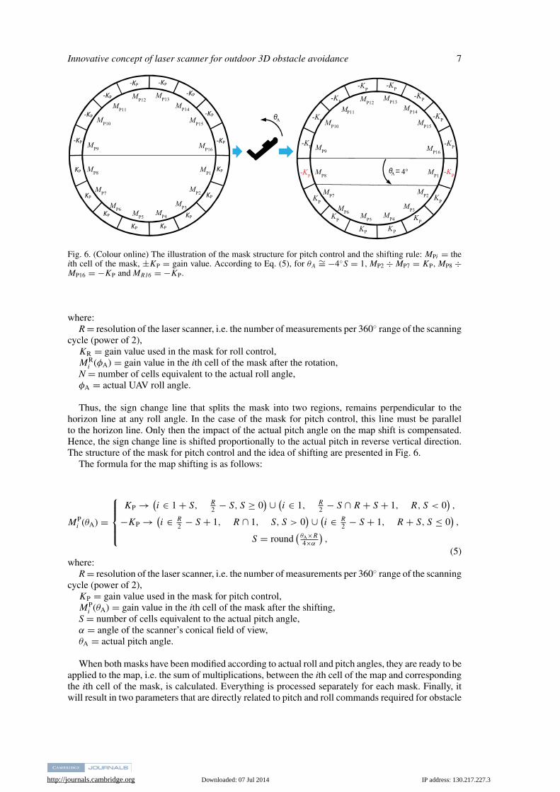
Fig. 5. (Colour online) The illustration of the mask structure for the roll control and the rotation rule: MRi =theith cell of the mask; ±KR =gain value. According to Eq. (4), for φA
∼= 45◦N = 2, MR7 ÷ MR14 = KR,MR1 ÷MR6 = −KR, and MR15 ÷ MR16 = −KR.
where:HmaxOB = maximum obstacle height,θmax = maximum UAV pitch angle (max ±30◦),α = angle of the scanner’s conical field of view.
Consequently, the map is ready to be utilized in a control algorithm. To generate the requiredcommands for pitch and roll controls, it is necessary to apply two special masks to the map. Thesemasks compensate the vehicle attitude and calculate the two independent parameters that are directlyrelated to roll and pitch commands. The first mask is for a roll angle control, and the second is for apitch angle control. The mask structure for the roll control is presented in Fig. 5. Cells of the maskhave a meaning of a signed gain. The mask is rotating contrariwise to the UAV’s rotation. Hence, theimpact of UAV’s roll angle on the map rotation is able to be compensated (Eq. (4)). The formula forthe mask rotation is as follows:
MRi (φA) =
⎧⎨⎩
KR → i ∈ R4 + N + 1, 3×R
4 + N, N = round(
φA×R
360◦
)−KR → i ∈ 1, R
4 + N ∩i ∈ 3×R4 + N + 1, R, N = round
(φA×R
360◦
), (4)
http://journals.cambridge.org Downloaded: 07 Jul 2014 IP address: 130.217.227.3
Innovative concept of laser scanner for outdoor 3D obstacle avoidance 7
KP
KP
KP KP KP
KP
KP
KP
-KP
-KP
-KP
-KP -KP -KP
-KP
-KP
A
-KP
KP
KP K K
KP
P P
KP
-KP
-KP
-KP
-KP -KP -KP
-KP
-KP
-KP
A 4°MP1
MP2 MP3
MP4 MP5 MP6
MP7
MP8
MP16
MP15 MP14
MP13 MP12 MP11
MP10
MP9
MP1
MP2 MP3
MP4 MP5 MP6
MP7
MP8
MP16
MP15 MP14
MP13 MP12 MP11
MP10
MP9
θ
θ
≅
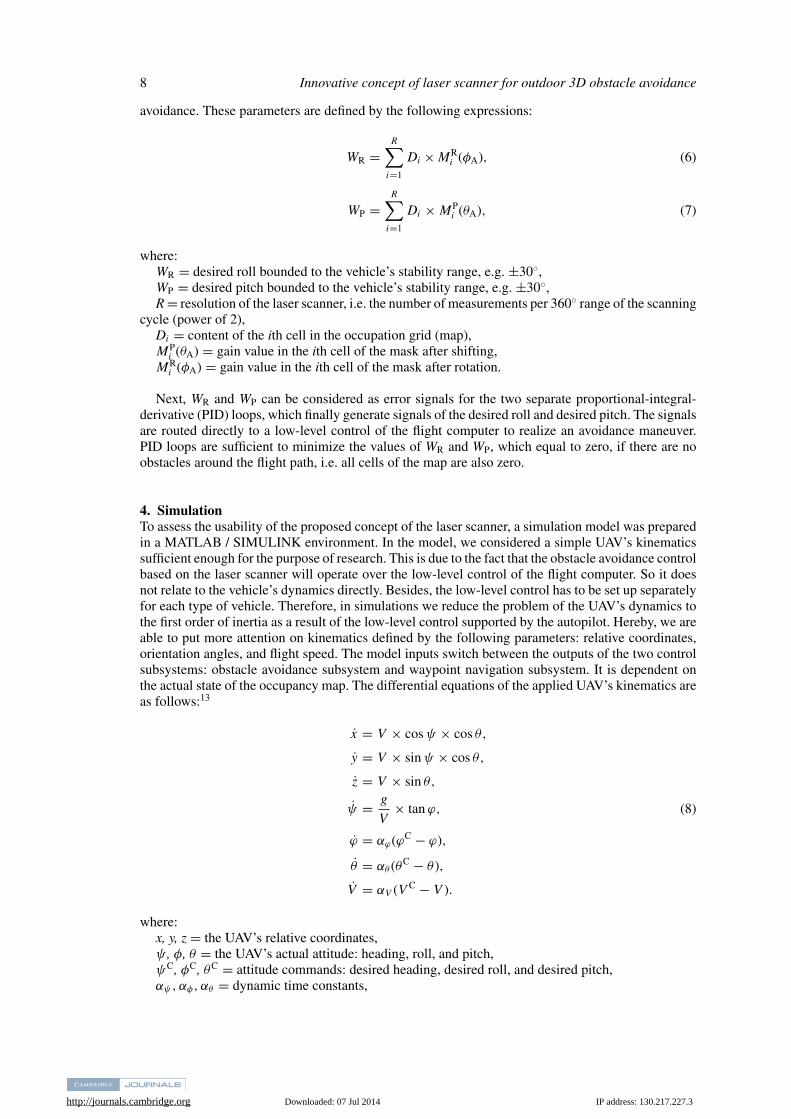
Fig. 6. (Colour online) The illustration of the mask structure for pitch control and the shifting rule: MPi = theith cell of the mask, ±KP = gain value. According to Eq. (5), for θA
∼= −4◦S = 1,MP2 ÷ MP7 = KP,MP8 ÷MP16 = −KP and MR16 = −KP.
where:R = resolution of the laser scanner, i.e. the number of measurements per 360◦ range of the scanning
cycle (power of 2),KR = gain value used in the mask for roll control,MR
i (φA) = gain value in the ith cell of the mask after the rotation,N = number of cells equivalent to the actual roll angle,φA = actual UAV roll angle.
Thus, the sign change line that splits the mask into two regions, remains perpendicular to thehorizon line at any roll angle. In the case of the mask for pitch control, this line must be parallelto the horizon line. Only then the impact of the actual pitch angle on the map shift is compensated.Hence, the sign change line is shifted proportionally to the actual pitch in reverse vertical direction.The structure of the mask for pitch control and the idea of shifting are presented in Fig. 6.
The formula for the map shifting is as follows:
MPi (θA) =
⎧⎪⎪⎨⎪⎪⎩
KP → (i ∈ 1 + S, R
2 − S, S ≥ 0) ∪ (
i ∈ 1, R2 − S ∩ R + S + 1, R, S < 0
),
−KP → (i ∈ R
2 − S + 1, R ∩ 1, S, S > 0) ∪ (
i ∈ R2 − S + 1, R + S, S ≤ 0
),
S = round(
θA×R4×α
),
(5)where:
R = resolution of the laser scanner, i.e. the number of measurements per 360◦ range of the scanningcycle (power of 2),
KP = gain value used in the mask for pitch control,MP
i (θA) = gain value in the ith cell of the mask after the shifting,S = number of cells equivalent to the actual pitch angle,α = angle of the scanner’s conical field of view,θA = actual pitch angle.
When both masks have been modified according to actual roll and pitch angles, they are ready to beapplied to the map, i.e. the sum of multiplications, between the ith cell of the map and correspondingthe ith cell of the mask, is calculated. Everything is processed separately for each mask. Finally, itwill result in two parameters that are directly related to pitch and roll commands required for obstacle
http://journals.cambridge.org Downloaded: 07 Jul 2014 IP address: 130.217.227.3
8 Innovative concept of laser scanner for outdoor 3D obstacle avoidance
avoidance. These parameters are defined by the following expressions:
WR =R∑
i=1
Di × MRi (φA), (6)
WP =R∑
i=1
Di × MPi (θA), (7)
where:WR = desired roll bounded to the vehicle’s stability range, e.g. ±30◦,WP = desired pitch bounded to the vehicle’s stability range, e.g. ±30◦,R = resolution of the laser scanner, i.e. the number of measurements per 360◦ range of the scanning
cycle (power of 2),Di = content of the ith cell in the occupation grid (map),MP
i (θA) = gain value in the ith cell of the mask after shifting,MR
i (φA) = gain value in the ith cell of the mask after rotation.
Next, WR and WP can be considered as error signals for the two separate proportional-integral-derivative (PID) loops, which finally generate signals of the desired roll and desired pitch. The signalsare routed directly to a low-level control of the flight computer to realize an avoidance maneuver.PID loops are sufficient to minimize the values of WR and WP, which equal to zero, if there are noobstacles around the flight path, i.e. all cells of the map are also zero.
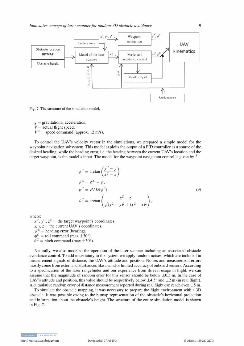
4. SimulationTo assess the usability of the proposed concept of the laser scanner, a simulation model was preparedin a MATLAB / SIMULINK environment. In the model, we considered a simple UAV’s kinematicssufficient enough for the purpose of research. This is due to the fact that the obstacle avoidance controlbased on the laser scanner will operate over the low-level control of the flight computer. So it doesnot relate to the vehicle’s dynamics directly. Besides, the low-level control has to be set up separatelyfor each type of vehicle. Therefore, in simulations we reduce the problem of the UAV’s dynamics tothe first order of inertia as a result of the low-level control supported by the autopilot. Hereby, we areable to put more attention on kinematics defined by the following parameters: relative coordinates,orientation angles, and flight speed. The model inputs switch between the outputs of the two controlsubsystems: obstacle avoidance subsystem and waypoint navigation subsystem. It is dependent onthe actual state of the occupancy map. The differential equations of the applied UAV’s kinematics areas follows:13
x = V × cos ψ × cos θ,
y = V × sin ψ × cos θ,
z = V × sin θ,
ψ = g
V× tan ϕ, (8)
ϕ = αϕ(ϕC − ϕ),
θ = αθ (θC − θ),
V = αV (V C − V ).
where:x, y, z = the UAV’s relative coordinates,ψ , φ, θ = the UAV’s actual attitude: heading, roll, and pitch,ψC, φC, θC = attitude commands: desired heading, desired roll, and desired pitch,αψ, αφ, αθ = dynamic time constants,
http://journals.cambridge.org Downloaded: 07 Jul 2014 IP address: 130.217.227.3
Innovative concept of laser scanner for outdoor 3D obstacle avoidance 9
Obstacle loca�on BITMAP
Obstacle height Model of the laser
scanner
Waypoint navigation
Masks and avoidance control
WP ≠0 ∪ WR≠0
UAV kinema�cs
φC, θ C
φC, θ C
x, y
, z, ψ
, φ, θ
,
φ, θ
Di
xC, yC, zC
Random noise
Random noise
Fig. 7. The structure of the simulation model.
g = gravitational acceleration,V = actual flight speed,V C = speed command (approx. 12 m/s).
To control the UAV’s velocity vector in the simulations, we prepared a simple model for thewaypoint navigation subsystem. This model exploits the output of a PID controller as a source of thedesired heading, while the heading error, i.e. the bearing between the current UAV’s location and thetarget waypoint, is the model’s input. The model for the waypoint navigation control is given by13
ψC = arctan
(yC − y
xC − x
)
ψE = ψC − ψ,
ϕC = PID(ψE) (9)
θC = arctan
(zC − z√
(yC − y)2 + (xC − x)2
),
where:xC, yC, zC = the target waypoint’s coordinates,x, y, z = the current UAV’s coordinates,ψE = heading error (bearing),φC = roll command (max ±30◦),θC = pitch command (max ±30◦).
Naturally, we also modeled the operation of the laser scanner including an associated obstacleavoidance control. To add uncertainty to the system we apply random noises, which are included inmeasurement signals of distance, the UAV’s attitude and position. Noises and measurement errorsmostly come from external disturbances like a wind or limited accuracy of onboard sensors. Accordingto a specification of the laser rangefinder and our experience from its real usage in flight, we canassume that the magnitude of random error for this sensor should be below ±0.5 m. In the case ofUAV’s attitude and position, this value should be respectively below ±4.5◦ and ±2 m (in real flight).A cumulative random error of distance measurement reported during real flight can reach even ±5 m.
To simulate the obstacle mapping, it was necessary to prepare the flight environment with a 3Dobstacle. It was possible owing to the bitmap representation of the obstacle’s horizontal projectionand information about the obstacle’s height. The structure of the entire simulation model is shownin Fig. 7.
http://journals.cambridge.org Downloaded: 07 Jul 2014 IP address: 130.217.227.3
10 Innovative concept of laser scanner for outdoor 3D obstacle avoidance
The proposed simulations are expected to identify limitations of the concept; especially theyshould answer if the concept is resistive to volatile relative positions and orientations between avehicle and an obstacle, while the scanning interval is equal to 1 s. Additionally, the results shoulddeliver information, which will be helpful in an analysis of the applicability of the concept in theflights through urban environments.
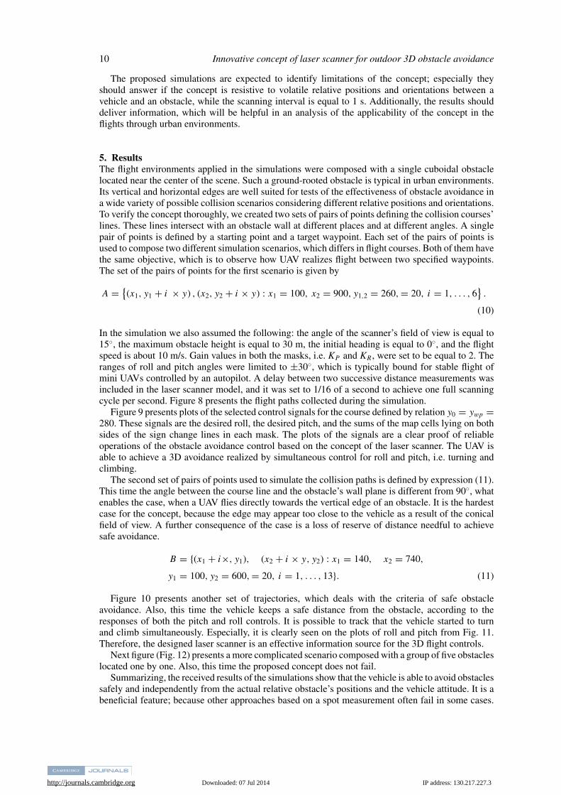
5. ResultsThe flight environments applied in the simulations were composed with a single cuboidal obstaclelocated near the center of the scene. Such a ground-rooted obstacle is typical in urban environments.Its vertical and horizontal edges are well suited for tests of the effectiveness of obstacle avoidance ina wide variety of possible collision scenarios considering different relative positions and orientations.To verify the concept thoroughly, we created two sets of pairs of points defining the collision courses’lines. These lines intersect with an obstacle wall at different places and at different angles. A singlepair of points is defined by a starting point and a target waypoint. Each set of the pairs of points isused to compose two different simulation scenarios, which differs in flight courses. Both of them havethe same objective, which is to observe how UAV realizes flight between two specified waypoints.The set of the pairs of points for the first scenario is given by
A = {(x1, y1 + i × y) , (x2, y2 + i × y) : x1 = 100, x2 = 900, y1,2 = 260, = 20, i = 1, . . . , 6
}.
(10)
In the simulation we also assumed the following: the angle of the scanner’s field of view is equal to15◦, the maximum obstacle height is equal to 30 m, the initial heading is equal to 0◦, and the flightspeed is about 10 m/s. Gain values in both the masks, i.e. KP and KR , were set to be equal to 2. Theranges of roll and pitch angles were limited to ±30◦, which is typically bound for stable flight ofmini UAVs controlled by an autopilot. A delay between two successive distance measurements wasincluded in the laser scanner model, and it was set to 1/16 of a second to achieve one full scanningcycle per second. Figure 8 presents the flight paths collected during the simulation.
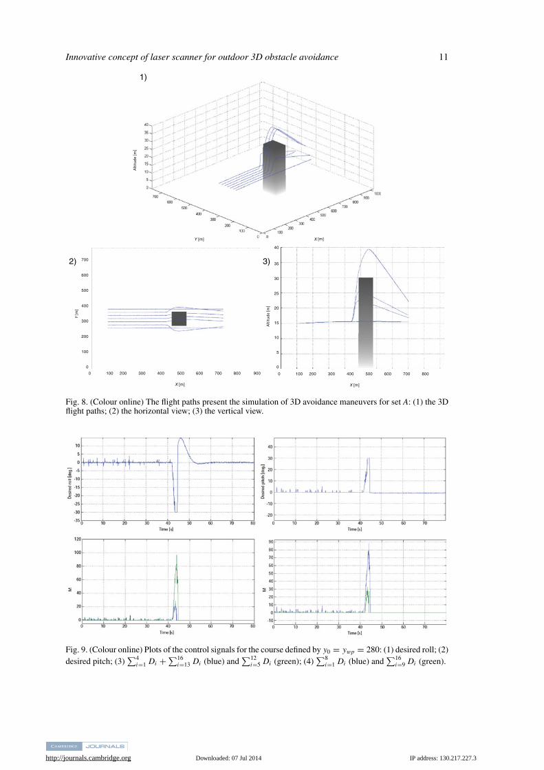
Figure 9 presents plots of the selected control signals for the course defined by relation y0 = ywp =280. These signals are the desired roll, the desired pitch, and the sums of the map cells lying on bothsides of the sign change lines in each mask. The plots of the signals are a clear proof of reliableoperations of the obstacle avoidance control based on the concept of the laser scanner. The UAV isable to achieve a 3D avoidance realized by simultaneous control for roll and pitch, i.e. turning andclimbing.
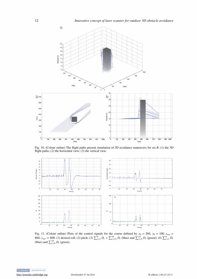
The second set of pairs of points used to simulate the collision paths is defined by expression (11).This time the angle between the course line and the obstacle’s wall plane is different from 90◦, whatenables the case, when a UAV flies directly towards the vertical edge of an obstacle. It is the hardestcase for the concept, because the edge may appear too close to the vehicle as a result of the conicalfield of view. A further consequence of the case is a loss of reserve of distance needful to achievesafe avoidance.
B = {(x1 + i×, y1), (x2 + i × y, y2) : x1 = 140, x2 = 740,
y1 = 100, y2 = 600, = 20, i = 1, . . . , 13}. (11)
Figure 10 presents another set of trajectories, which deals with the criteria of safe obstacleavoidance. Also, this time the vehicle keeps a safe distance from the obstacle, according to theresponses of both the pitch and roll controls. It is possible to track that the vehicle started to turnand climb simultaneously. Especially, it is clearly seen on the plots of roll and pitch from Fig. 11.Therefore, the designed laser scanner is an effective information source for the 3D flight controls.
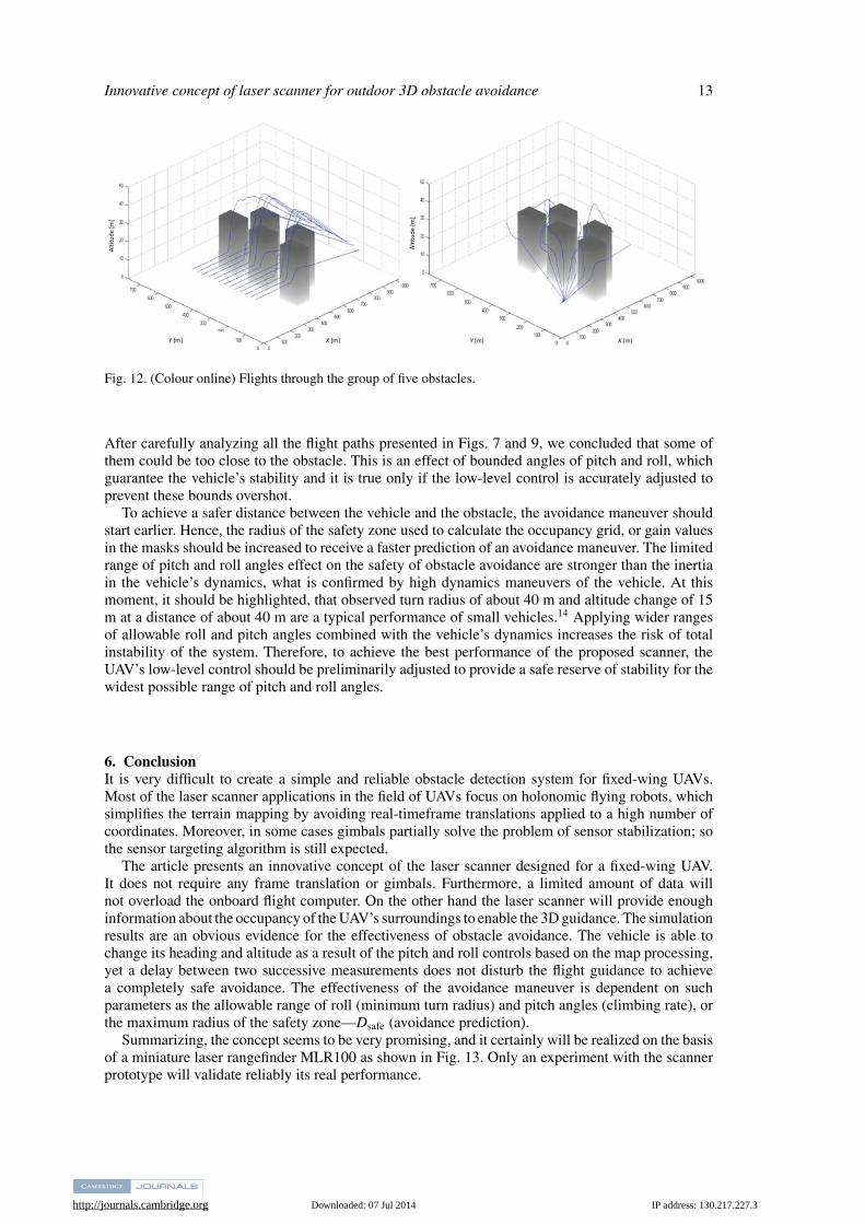
Next figure (Fig. 12) presents a more complicated scenario composed with a group of five obstacleslocated one by one. Also, this time the proposed concept does not fail.
Summarizing, the received results of the simulations show that the vehicle is able to avoid obstaclessafely and independently from the actual relative obstacle’s positions and the vehicle attitude. It is abeneficial feature; because other approaches based on a spot measurement often fail in some cases.
http://journals.cambridge.org Downloaded: 07 Jul 2014 IP address: 130.217.227.3
Innovative concept of laser scanner for outdoor 3D obstacle avoidance 11
1)
3)2) 700
600
500
400
300
200
100
0
0 100 200 300 400 500 600 700 800 900
X [m]
0 100 200 300 400 500 600 700 800
X [m]
40
35
30
25
20
15
10
5
0
Y [m
]
Altit
ude
[m]
Altit
ude
[m]
Y [m] X [m]
Fig. 8. (Colour online) The flight paths present the simulation of 3D avoidance maneuvers for set A: (1) the 3Dflight paths; (2) the horizontal view; (3) the vertical view.
Fig. 9. (Colour online) Plots of the control signals for the course defined by y0 = ywp = 280: (1) desired roll; (2)desired pitch; (3)
∑4i=1 Di + ∑16
i=13 Di (blue) and∑12
i=5 Di (green); (4)∑8
i=1 Di (blue) and∑16
i=9 Di (green).
http://journals.cambridge.org Downloaded: 07 Jul 2014 IP address: 130.217.227.3
12 Innovative concept of laser scanner for outdoor 3D obstacle avoidance
Fig. 10. (Colour online) The flight paths present simulation of 3D avoidance maneuvers for set B: (1) the 3Dflight paths; (2) the horizontal view; (3) the vertical view.
Desir
ed ro
ll [d
eg.]
Desir
ed p
itch
[deg
.]
M M
10 20 30 40 50 60 70 80 Time [s]
10
20 30 40 50 60 70 80
Time [s]
10 20 30 40 50 60 70
Time [s]
10 20 30 40 50 60 70
Time [s]
40
30
20
10
0
-10
-20
25
20
15
10
5
0
-5
-10
-15
140
120
100
80
60
40
20
0
150
100
50
0
0 0
00
Fig. 11. (Colour online) Plots of the control signals for the course defined by x0 = 260, y0 = 100, xwp =860, ywp = 600: (1) desired roll; (2) pitch; (3)
∑4i=1 Di + ∑16
i=13 Di (blue) and∑12
i=5 Di (green); (4)∑8
i=1 Di
(blue) and∑16
i=9 Di (green).
http://journals.cambridge.org Downloaded: 07 Jul 2014 IP address: 130.217.227.3
Innovative concept of laser scanner for outdoor 3D obstacle avoidance 13
Y [m] Y [m] X [m] X [m]
Al�t
ude
[m]
Al�t
ude
[m]
Fig. 12. (Colour online) Flights through the group of five obstacles.
After carefully analyzing all the flight paths presented in Figs. 7 and 9, we concluded that some ofthem could be too close to the obstacle. This is an effect of bounded angles of pitch and roll, whichguarantee the vehicle’s stability and it is true only if the low-level control is accurately adjusted toprevent these bounds overshot.
To achieve a safer distance between the vehicle and the obstacle, the avoidance maneuver shouldstart earlier. Hence, the radius of the safety zone used to calculate the occupancy grid, or gain valuesin the masks should be increased to receive a faster prediction of an avoidance maneuver. The limitedrange of pitch and roll angles effect on the safety of obstacle avoidance are stronger than the inertiain the vehicle’s dynamics, what is confirmed by high dynamics maneuvers of the vehicle. At thismoment, it should be highlighted, that observed turn radius of about 40 m and altitude change of 15m at a distance of about 40 m are a typical performance of small vehicles.14 Applying wider rangesof allowable roll and pitch angles combined with the vehicle’s dynamics increases the risk of totalinstability of the system. Therefore, to achieve the best performance of the proposed scanner, theUAV’s low-level control should be preliminarily adjusted to provide a safe reserve of stability for thewidest possible range of pitch and roll angles.
6. ConclusionIt is very difficult to create a simple and reliable obstacle detection system for fixed-wing UAVs.Most of the laser scanner applications in the field of UAVs focus on holonomic flying robots, whichsimplifies the terrain mapping by avoiding real-timeframe translations applied to a high number ofcoordinates. Moreover, in some cases gimbals partially solve the problem of sensor stabilization; sothe sensor targeting algorithm is still expected.
The article presents an innovative concept of the laser scanner designed for a fixed-wing UAV.It does not require any frame translation or gimbals. Furthermore, a limited amount of data willnot overload the onboard flight computer. On the other hand the laser scanner will provide enoughinformation about the occupancy of the UAV’s surroundings to enable the 3D guidance. The simulationresults are an obvious evidence for the effectiveness of obstacle avoidance. The vehicle is able tochange its heading and altitude as a result of the pitch and roll controls based on the map processing,yet a delay between two successive measurements does not disturb the flight guidance to achievea completely safe avoidance. The effectiveness of the avoidance maneuver is dependent on suchparameters as the allowable range of roll (minimum turn radius) and pitch angles (climbing rate), orthe maximum radius of the safety zone—Dsafe (avoidance prediction).
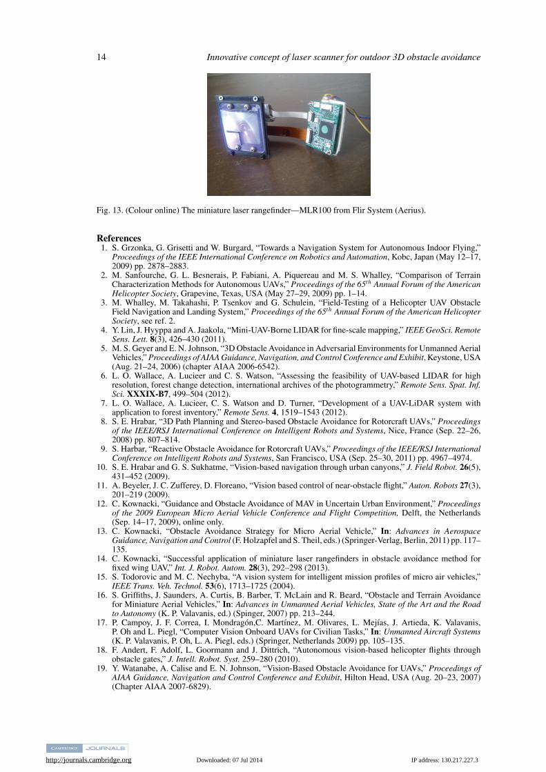
Summarizing, the concept seems to be very promising, and it certainly will be realized on the basisof a miniature laser rangefinder MLR100 as shown in Fig. 13. Only an experiment with the scannerprototype will validate reliably its real performance.
http://journals.cambridge.org Downloaded: 07 Jul 2014 IP address: 130.217.227.3
14 Innovative concept of laser scanner for outdoor 3D obstacle avoidance
Fig. 13. (Colour online) The miniature laser rangefinder—MLR100 from Flir System (Aerius).
References1. S. Grzonka, G. Grisetti and W. Burgard, “Towards a Navigation System for Autonomous Indoor Flying,”
Proceedings of the IEEE International Conference on Robotics and Automation, Kobc, Japan (May 12–17,2009) pp. 2878–2883.
2. M. Sanfourche, G. L. Besnerais, P. Fabiani, A. Piquereau and M. S. Whalley, “Comparison of TerrainCharacterization Methods for Autonomous UAVs,” Proceedings of the 65th Annual Forum of the AmericanHelicopter Society, Grapevine, Texas, USA (May 27–29, 2009) pp. 1–14.
3. M. Whalley, M. Takahashi, P. Tsenkov and G. Schulein, “Field-Testing of a Helicopter UAV ObstacleField Navigation and Landing System,” Proceedings of the 65th Annual Forum of the American HelicopterSociety, see ref. 2.
4. Y. Lin, J. Hyyppa and A. Jaakola, “Mini-UAV-Borne LIDAR for fine-scale mapping,” IEEE GeoSci. RemoteSens. Lett. 8(3), 426–430 (2011).
5. M. S. Geyer and E. N. Johnson, “3D Obstacle Avoidance in Adversarial Environments for Unmanned AerialVehicles,” Proceedings of AIAA Guidance, Navigation, and Control Conference and Exhibit, Keystone, USA(Aug. 21–24, 2006) (chapter AIAA 2006-6542).
6. L. O. Wallace, A. Lucieer and C. S. Watson, “Assessing the feasibility of UAV-based LIDAR for highresolution, forest change detection, international archives of the photogrammetry,” Remote Sens. Spat. Inf.Sci. XXXIX-B7, 499–504 (2012).
7. L. O. Wallace, A. Lucieer, C. S. Watson and D. Turner, “Development of a UAV-LiDAR system withapplication to forest inventory,” Remote Sens. 4, 1519–1543 (2012).
8. S. E. Hrabar, “3D Path Planning and Stereo-based Obstacle Avoidance for Rotorcraft UAVs,” Proceedingsof the IEEE/RSJ International Conference on Intelligent Robots and Systems, Nice, France (Sep. 22–26,2008) pp. 807–814.
9. S. Harbar, “Reactive Obstacle Avoidance for Rotorcraft UAVs,” Proceedings of the IEEE/RSJ InternationalConference on Intelligent Robots and Systems, San Francisco, USA (Sep. 25–30, 2011) pp. 4967–4974.
10. S. E. Hrabar and G. S. Sukhatme, “Vision-based navigation through urban canyons,” J. Field Robot. 26(5),431–452 (2009).
11. A. Beyeler, J. C. Zufferey, D. Floreano, “Vision based control of near-obstacle flight,” Auton. Robots 27(3),201–219 (2009).
12. C. Kownacki, “Guidance and Obstacle Avoidance of MAV in Uncertain Urban Environment,” Proceedingsof the 2009 European Micro Aerial Vehicle Conference and Flight Competition, Delft, the Netherlands(Sep. 14–17, 2009), online only.
13. C. Kownacki, “Obstacle Avoidance Strategy for Micro Aerial Vehicle,” In: Advances in AerospaceGuidance, Navigation and Control (F. Holzapfel and S. Theil, eds.) (Springer-Verlag, Berlin, 2011) pp. 117–135.
14. C. Kownacki, “Successful application of miniature laser rangefinders in obstacle avoidance method forfixed wing UAV,” Int. J. Robot. Autom. 28(3), 292–298 (2013).
15. S. Todorovic and M. C. Nechyba, “A vision system for intelligent mission profiles of micro air vehicles,”IEEE Trans. Veh. Technol. 53(6), 1713–1725 (2004).
16. S. Griffiths, J. Saunders, A. Curtis, B. Barber, T. McLain and R. Beard, “Obstacle and Terrain Avoidancefor Miniature Aerial Vehicles,” In: Advances in Unmanned Aerial Vehicles, State of the Art and the Roadto Autonomy (K. P. Valavanis, ed.) (Spinger, 2007) pp. 213–244.
17. P. Campoy, J. F. Correa, I. Mondragon,C. Martınez, M. Olivares, L. Mejıas, J. Artieda, K. Valavanis,P. Oh and L. Piegl, “Computer Vision Onboard UAVs for Civilian Tasks,” In: Unmanned Aircraft Systems(K. P. Valavanis, P. Oh, L. A. Piegl, eds.) (Springer, Netherlands 2009) pp. 105–135.
18. F. Andert, F. Adolf, L. Goormann and J. Dittrich, “Autonomous vision-based helicopter flights throughobstacle gates,” J. Intell. Robot. Syst. 259–280 (2010).
19. Y. Watanabe, A. Calise and E. N. Johnson, “Vision-Based Obstacle Avoidance for UAVs,” Proceedings ofAIAA Guidance, Navigation and Control Conference and Exhibit, Hilton Head, USA (Aug. 20–23, 2007)(Chapter AIAA 2007-6829).

http://journals.cambridge.org Downloaded: 07 Jul 2014 IP address: 130.217.227.3
Innovative concept of laser scanner for outdoor 3D obstacle avoidance 15
20. C. Kowacki, “Successful application of miniature laser rangefinders in obstacle avoidance method for fixedwing micro UAV,” Int. J. Robot. Autom., 28(3), 292–298 (2013).
21. M. Achtelik, A. Bachrach, R. Heb, S. Prentice and N. Roy, “Stereo Vision and Laser Odometry forAutonomous Helicopters in GPS-denied Indoor Environments,” Proceedings of the 11th SPIE UnmannedSystems Technology, vol. 7332 733219, Orlando, Florida, USA (Apr. 30, 2009) pp. 1–10.
22. S. Scherer, S. Singh, L. Chamberlain and M. Elgersma, “Flying fast and low among obstacles: Methodologyand experiments,” Int. J. Robot. Res. 27(5), 549–574 (2008).
23. B. Call, B. R. Randy, T. C. Clark, “Obstacle Avoidance For Unmanned Air Vehicles Using Image FeatureTracking,” Proceedings of AIAA Guidance, Navigation, and Control Conference and Exhibit, Keystone,USA (Aug. 21–24, 2006) (chapter AIAA 2006-6541).


