Download - 95337422-Fluid-Power-3-26

THE BFPA
The BRITISH FLUID POWER ASSOCIATIONrepresents over 90% of the manufacturers andsuppliers of hydraulic and pneumatic equipment in theUnited Kingdom. It is the recognised authority for theindustry on technical standards and marketing data andis your assurance for customer satisfaction.
For positive commitment to quality and customercare, use a product of a BFPA member company,obtained either from a BFPA member or a member ofthe British Fluid Power Distributors Association(BFPDA).
Neil PercivalDirector (BFPA)
2

GENERAL• Terminology ……………………………………………………………………………………4
• Systems of Units and Conversions …………………………………………5
• National and International Standards ………………………………………6
• Hydraulic and Pneumatic Symbols …………………………………………8
• Electrical Data ……………………………………………………………………………10
• General Formulae ………………………………………………………………………12
• Hydraulic Cylinders ……………………………………………………………………14
• Pipes and Hoses…………………………………………………………………………15
• Fluids, Seals and Contamination Control ……………………………16
• Accumulators ………………………………………………………………………………19
• Cooling and Heating …………………………………………………………………20
• Pneumatic Valve Flow ………………………………………………………………21
• Pneumatic Cylinders …………………………………………………………………21
• Filtration, Lubrication and Seals ……………………………………………23
• Compressors ………………………………………………………………………………24
• BFPA Publications …………………………………………Inside back cover
3
CONTENTS
GE
NE
RA
LH
YD
RA
UL
IC
SP
NE
UM
AT
IC
S
Page No.
TERMINOLOGY
The main source of fluid power terms and definitions is the International Standard - ISO 5598- Fluid Power Systems and Components - Vocabulary, however, new definitions are arisingfrom recent work on E.U. - CEN standards.
The following are just a few of the fluid power terms in every day use for hydraulic andpneumatic applications:-
Fluid power - The means whereby signals and energy can be transmitted, controlled anddistributed, using a fluid as the medium.
Hydraulics - Science and technology which deals with the laws governing liquid flow andpressure.
Pneumatics - Science and technology which deals with the use of air or neutral gases as thefluid power medium.
System - Arrangement of interconnected components which transmits and controls fluidpower energy.
Machinery - An assembly of linked parts or components, at least one of which moves, withthe appropriate actuators, control and power circuits etc., joined together for a specificapplication.
Component - An individual unit (e.g. actuator, valve, filter) comprising one or more parts,designed to be a functional part of a fluid power component or system.
Actuator - A device which converts energy into force and movement. The movement may belinear (e.g. cylinder), semi-rotary (e.g. torque unit), or rotary (e.g. motor).
Operating conditions - Operating conditions are indicated by the numerical values of thevarious factors relating to any given, specific application of a unit. These factors may varyduring the course of operations.
Working pressure - Pressure at which the apparatus is being operated for a given application.
System pressure - Pressure measured at the inlet to the first valve or at pump outlet (normallythe relief valve setting).
Pilot pressure - pressure in a pilot line or circuit.
Hydraulic pumps - Units which transform mechanical energy into hydraulic energy.
Compressors - Devices which cause a gas to flow, against a pressure: they convert mechanicalenergy into pneumatic fluid power.
Directional control valve - Device connecting or isolating one or more flow paths.
Control mechanisms - The means whereby components change their state. Controlmechanisms may be manual, mechanical, pressure or electrical in operation.
Pressure relief valve - Valve which limits maximum pressure by exhausting fluid to tankwhen the required pressure is exceeded.
4
GE
NE
RA
L

5
GE
NE
RA
L
Systems of Units and Conversions
Quantity SI Imperial
MASS kilogram kg pound mass lb1lb = 0.4536 kg
FORCE newton N pound force lbf1lbf = 4.45N
WORK joule J foot pound force ft lbf1ft lbf = 1.356J
POWER watt w foot pound force per second ft lbf/sec1ft lbf/sec = 1.356Whorse power hp1hp = 745.7W
VELOCITY metre per second m/s feet per second ft/s1m/s = 3.28 ft/s
LENGTH metre m inch in1m = 39. 37 inmicron µm1µm = 10- 6m
PRESSURE newton per square metre N/m2 pound force per square inch lbf/in2
1 bar = 105 N/m2 1lbf/in2 = 6897 N/m2
1 atmosphere =1.013 x 10⁵ N/m2
1Pa = 1N/m2
DENSITY kilogram per cubic metre kg/m3 pound mass per cubic foot lb/ft 3
1lb/ft 3 = 16.02kg/m3
AREA square metre m2 square inch in2
1m2 = 1550 in2 1in2 = 0.645 x 10- 3 m2
1in2 = 6.45cm2
VOLUME cubic metre m3 cubic inch in3
1m3 = 10 3 litre 1in3 = 16.39 x 10⁻⁶ m3
1m3 = 220 gall gallon gall1gall = 277.4in3
1gall = 0.00454m3
cubic foot ft3
1ft3 = 6.23gall
FLOW RATE cubic metres per second m3/s cubic inches per minute in3/min1m3/s = 13.2 x 10³ gall/min gallons per minute gall/min
1 l/min = 0.22 gall/min1 l/min = 1.66 x 10⁻⁵m3/s1ft3/min = 28.32 x 10⁻³ m3/min
VISCOSITY 1cSt = 10-6m2/s
6
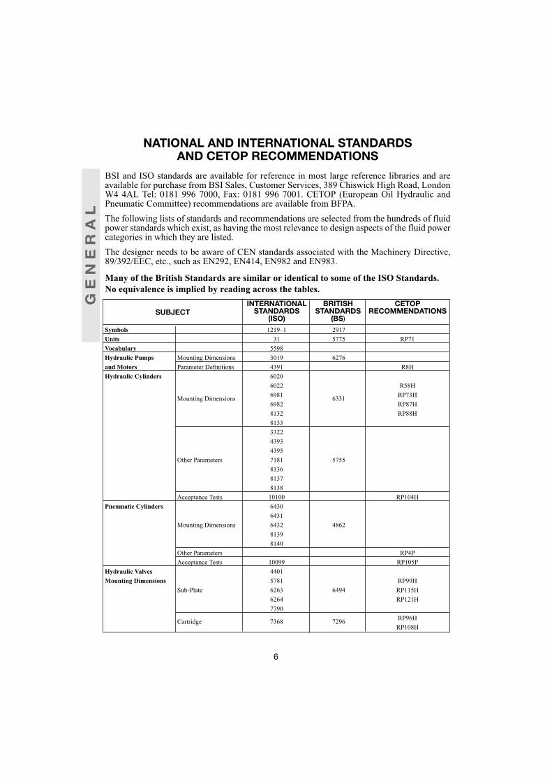
NATIONAL AND INTERNATIONAL STANDARDSAND CETOP RECOMMENDATIONS
BSI and ISO standards are available for reference in most large reference libraries and areavailable for purchase from BSI Sales, Customer Services, 389 Chiswick High Road, LondonW4 4AL Tel: 0181 996 7000, Fax: 0181 996 7001. CETOP (European Oil Hydraulic andPneumatic Committee) recommendations are available from BFPA.The following lists of standards and recommendations are selected from the hundreds of fluidpower standards which exist, as having the most relevance to design aspects of the fluid powercategories in which they are listed.The designer needs to be aware of CEN standards associated with the Machinery Directive,89/392/EEC, etc., such as EN292, EN414, EN982 and EN983.
Many of the British Standards are similar or identical to some of the ISO Standards.No equivalence is implied by reading across the tables.
Symbols 1219–1 2917Units 31 5775 RP71Vocabulary 5598Hydraulic Pumps Mounting Dimensions 3019 6276and Motors Parameter Definitions 4391 R8HHydraulic Cylinders 6020
6022 R58H
Mounting Dimensions 6981 6331 RP73H6982 RP87H8132 RP88H8133332243934395
Other Parameters 7181 5755813681378138
Acceptance Tests 10100 RP104HPneumatic Cylinders 6430
6431Mounting Dimensions 6432 4862
81398140
Other Parameters RP4PAcceptance Tests 10099 RP105P
Hydraulic Valves 4401Mounting Dimensions 5781 RP99H
Sub-Plate 6263 6494 RP115H6264 RP121H7790
Cartridge 7368 7296 RP96HRP108H
SUBJECTINTERNATIONAL
STANDARDS(ISO)
BRITISHSTANDARDS
(BS)
CETOPRECOMMENDATIONS
GE
NE
RA
L

Pneumatic Valves Mounting Dimensions 5599 7389 RP114PSeals & Seal Housings 3601-1 1806
3601-4 451810766 51065597 5751
Dimensions 6194 6241619565477425
Connectors & Port 7 21Dimensions 228 2779
6149 43687241-1 5200
Hydraulic & 8434 5327 RP63HPneumatic 1179 5380 RP80
9974 653711926 7198/1
7417Steel Tubes 2604 7416
4200 3602/1Nylon Tubing 7628-1 5409/1Hydraulic Fluids Classifications 6743-4 4231 RP123H
3448 6413/4Fire Resistant 7745 7287
R39H
Specifications RP91HRP97HRP110H
Hydraulic Filters RP92H
Designation 7744 6851 RP98HRT117HRT118H
FRL Specification 6301Contamination 3938 5540/4Levels 4406 5540/5
7265Hose & Hose 1436 3832Assemblies 3862 4586
Specifications 3949 4749 R344079 49836805 65967751
Pneumatic 2398 51185774 6066
Accumulators 5596 7201 RP47HRP62H
Reservoirs 6525Electrical 4400 5630Connectors 6952 6361Systems Fluid Power 1219-2 7388
(Hyd. & Pneu.) 4575/3Hydraulic 4413 4575/1Pneumatic 4414 4575/2
7
SUBJECTINTERNATIONAL
STANDARDS(ISO)
BRITISHSTANDARDS
(BS)
CETOPRECOMMENDATIONS
GE
NE
RA
L

8
HYDRAULIC AND PNEUMATIC SYMBOLSISO 1219-1 covers graphic symbols for both hydraulic and pneumatic equipment. this
standard was amended in1991
Symbol Description Symbol Description
Source of energy Hydraulic cylinder-Hydraulic -Double-acting
Source of energy Pneumatic cylinder-Pneumatic -Double-acting
Hydraulic pump CylinderFixed displacement -Double-actingOne flow direction -Double-ended
Piston rodPneumatic motor Pneumatic cylinderFixed displacement -single-actingOne flow direction -Spring return
Hydraulic pump CylinderVariable displacement -Double-actingTwo flow directions Adjustable cushions
both ends Hydraulic motor Pressure intensiferFixed displacement -Single fluidOne flow direction -Hydraulic
Hydraulic motor Semi-rotary actuatorVariable displacement -Double-actingTwo flow directions Two -Hydraulicdirections of rotationAir compressor Semi-rotary actuator
-single-acting-Spring return-Pneumatic
Accumulator - Gas Telescopic cylinderloaded -Double-acting
-Hydraulic
Air receiver Electric motor(From IEC 617)
x y
M
GE
NE
RA
L
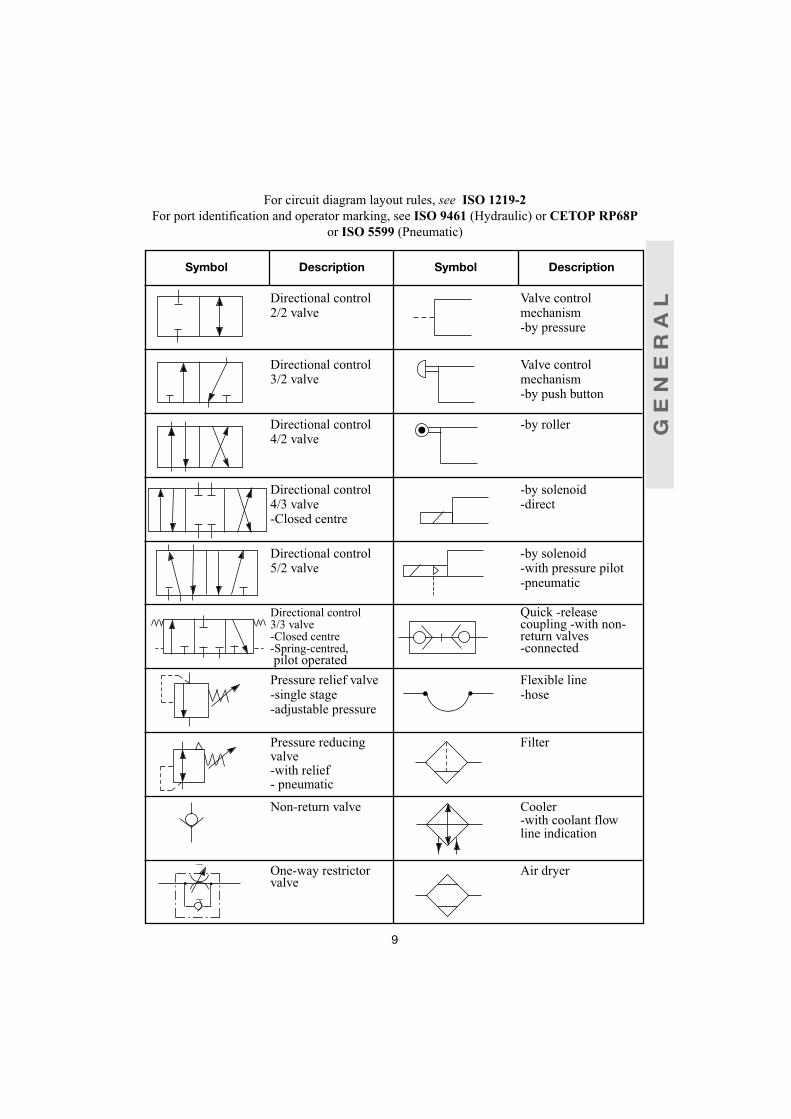
For circuit diagram layout rules, see ISO 1219-2 For port identification and operator marking, see ISO 9461 (Hydraulic) or CETOP RP68P
or ISO 5599 (Pneumatic)
Symbol Description Symbol Description
Directional control Valve control2/2 valve mechanism
-by pressure
Directional control Valve control3/2 valve mechanism
-by push button
Directional control -by roller4/2 valve
Directional control -by solenoid4/3 valve -direct-Closed centre
Directional control -by solenoid5/2 valve -with pressure pilot
-pneumatic
Directional control Quick -release3/3 valve coupling -with non--Closed centre return valves-Spring-centred, -connectedpilot operatedPressure relief valve Flexible line-single stage -hose-adjustable pressure
Pressure reducing Filtervalve-with relief- pneumatic
Non-return valve Cooler-with coolant flowline indication
One-way restrictor Air dryervalve
9
GE
NE
RA
L

ELECTRICAL DATA
Solenoid – an electro-mechanical device used as a control mechanism.Modes of Action – 4 modes of action generally available:
1) Single-acting – solenoid acts in one direction only – spring return
2) Double-acting – solenoid acts in both directions of valve movement
3) Latching/reversing stroke – solenoid moves from one extremity to the other in response tosuccessive electrical signals
4) Proportional – solenoid adopts a position according to the magnitude of the signal
received.
General types – Direct solenoid – The armature or core of the solenoid is directly linked to thevalve spool.
Pilot solenoid – Operates a small pilot valve which allows pressure to act upon the valve spool.
Technical Characteristics:-
Voltage – Generally 24v to 240v. Voltage tolerance – typically + or – 10%.
Power consumption – from 2 watts – miniature pilot type, up to 42 watts – large direct solenoid.Most solenoids are continuously rated, i.e. they can be energised forlong periods.
Response times – Direct solenoid generally 10/12 milliseconds– Pilot solenoid generally 25/40 milliseconds
Insulation class – indicates limiting temperature of coil material– typically 'H' – 180°C.
Tropicalisation – indicates resistance of coil to insect attack, humidity etc.
10
GE
NE
RA
L

Electrical connections – Terminal box – valve enclosure contains a permanent terminal block
to which electrical wiring can be connected – frequently with conduit thread opening –
solenoid body has a two or three pin socket which accepts a mating plug – see
ISO 4400/BS 6361. Plug entry usually has a conduit thread and plugs are available with a
variety of indicators to show if the solenoid is energised. Flying leads – some solenoids are
provided with simple loose leads for connection to an external terminal block.
Manual overrides – Solenoid valves are often supplied with a manual override as standard, so
that the valve can be operated independent of an electrical supply, e.g. for test purposes.
For direct solenoids, the manual override is usually mechanical, acting direct on the valve
member. For pilot solenoids, the pilot valve has a simple hand or tool operated switch,
operation of which allows entry of pressure to act on the valve spool.
Protection class – indicates the resistance of the solenoid enclosure, terminal box and/or plug
to entry of dirt, water etc. – typically IP65 or IP66 – the number is significant – see
IEC 144/BS 5420
Explosive atmospheres – Special solenoid valves are required for use in explosive atmospheres
and the areas of use are classified into "zones" of potential risk:
Zone 0 – risk of explosion is continuously present.Zone 1 – risk is frequently presentZone 2 – risk is not present under normal conditions, but is a possibility.
A flameproof or explosion proof valve for use in a Zone 2 area, may only require some
modifications to the normal terminal block or plug and socket employed, to reduce the
possibility of sparking.
Zone 0 and Zone 1 conditions will require a special valve and terminal box enclosure so that any
explosion will be contained within the valve body. Such enclosures require special certification
by Health and Safety Executive – see BS 4683, BS 5501 and BS CP 1003 (withdrawn).
Intrinsically safe solenoids are special low–power units which are operated in conjunction with
special protective devices, such as Zener barriers. These reduce the power supply to such low
levels that sparks cannot occur.
11
GE
NE
RA
L

GENERAL FORMULAEHydraulic
a) PUMPS AND MOTORS
FLOW RATE (l/min) Q =D.n
1000
SHAFT TORQUE (Nm) T =D.p
20π
SHAFT POWER (kW) P =T.n
9554
HYDRAULIC POWER (kW) P =Q.p
600
c) FLOWFLOW (l/min) Q α Δp
Δp = Pressure change (bar)
PRESSURE LOSS IN PIPES
This chart gives the approximate pressure drop in smooth bore straight pipes, in bar per 3m length. Bends and fittings will increase the above pressure losses and manufacturers should be consulted for more accurate figures
12
b) CYLINDERS
PRESSURE (N/m2) p =FA
FLOW RATE (l /min) Q = 60.A.v.103
F = Force (N)A = Area (m2)v = Velocity (m/s)p = Pressure (bar)D = Displacement (cm3/rev)n = rev per min
ie, if you double the flow you get 4times the pressure change
GE
NE
RA
L
Flow in Tube bore size in mml/min
5 7 10 13 16 21 25 30 361 0.69 0.222 1.38 0.443 2.07 0.66 0.175 4.14 1.24 0.24
7.5 6.55 1.72 0.3110 3.10 0.38 0.1415 5.38 0.69 0.21 0.0820 1.10 0.30 0.1430 2.21 0.69 0.25 0.0440 1.17 0.45 0.08 0.0450 0.59 0.12 0.07 0.0375 1.31 0.23 0.14 0.06 0.02
100 0.41 0.22 0.13 0.03150 0.45 0.23 0.06200 0.41 0.10250 0.16

13
GE
NE
RA
L
Pneumatica) FLOW THROUGH PIPES:
Δp = 1.6 x 10⁸ x (Q x 10-3)1.85 x L x 10-3
d5 x p
WhereΔp = Pressure drop (bar) Q = Free air flow (m3/s) = l/s x 10-3
L = Pipe length (metres)
b) VELOCITY THROUGH PIPES:v = 1273Q
(p + 1) d2
Wherev = Flow velocity in metres/sp = Initial pressure (bar)d = Inside pipe diameter (mm)
If the free air flow is known, the minimum inside diameter to keep velocity below 6 m/s, can be
found from: d (mm) = 212 x Q(p + 1)
For normal installations, where the pressure is about 7 bar gauge, this can be simplified to:
d (mm) should be greater than 5 x Q

HYDRAULIC CYLINDERS
Output force and maximum rod lengthsExample: Knowing the output force required (200kN) and the pressure of the system (160 bar),
connect Output force through pressure to cut cylinder diameter. Answer: 125 millimetres.To find the maximum length of a piston rod. Connect output force required (200kN) through rod
diameter (70mm) to cut the maximum rod length scale; this gives you the (Lm) dimension. Answer:2800mm.
To find the actual length stroke (LA) for a specific mounting use formulae below.
Maximum stroke lengths for specific mounting cases
For intermediate trunnion positions scaled multiplier factors must be taken. Clevis and spherical eyemountings have the same factor as eye mountings.Example: Having found Lm (2800mm) for rear flange mount with eye rod endLA = Lm x 0.4 = 2800 x 0.4 = 1120mm.
14
7.5.8
.9
1
20
25
30
351.5
40
50 2
2.560
370
80
3.590
100 4
5
150 6
7
8
9
200
10250
300
2002000
1000
50500400
4030
20 300
200
10010
1500
1000
300 000
200 000
150 000
500100 000
400
300
50 000200
30 000
20 000100
15 000
5010 000
40
30
500020
15
4000
3000
102000
1500
51000
.5
15 .6
.7
20 .8
.9
25 1
30
1.535
40
250
60
70
803
90
100 4
5
150 6
7
200 8
30
35
401000
50
1500 60
70
2000 80
90
2500 100
150
3500
4000
2005000
6000
7000
3008000
9000
40010 000
500
15 000
3000
2.5
40 000
150
40003000
100
Cyl
inde
r Dia
. – m
m
Cyl
inde
r Dia
. – in
ches
bar
lbf/i
n2
Rod
Dia
. – m
m
Rod
Dia
. – in
ches
Rod
Len
gth
– Lm
(mm
)
Rod
Len
gth
– Lm
(inc
hes)
Pressure
kN lbs
Foot mounted, eye rod end ………………………LA = Lm x 0.8Foot mounted, rigidly supported rod ……………LA = LmFront flange, eye rod end ………………………LA = Lm x 0.8Front flange, rigidly supported rod ………………LA = LmRear flange, eye rod end …………………………LA = Lm x 0.4
Rear flange, rigidly supported rod ………………LA = Lm x 0.8Rear eye, eye rod end ……………………………LA = Lm x 0.3Trunnion head end, eye rod end …………………LA = Lm x 0.3Trunnion gland end, eye rod end ………………LA = Lm x 0.6Trunnion gland end, rigidly supported end………LA = Lm x 0.8
HY
DR
AU
LI
CS

HYDRAULIC PIPESAND HOSES
Nomogram for determining pipe sizes inrelation to flow rates and recommendedvelocity ranges.Based on the formula:
Velocity of fluid in pipe(m/s) = Flow rate (l/min) x 21.22d2
where d = Bore of pipe (mm)Recommended velocity ranges based onoils having a maximum viscosity grade of70cSt at 40°C and operating between 18°Cand 70°C.
For further information, see :BFPA/P7 – Guidelines to the selection and application of tube couplings for use in
fluid power systemsBFPA/P47 – Guidelines for the use of fluid power hose assemblies.
15
HY
DR
AU
LI
CS
400
300
200
150
100
50
40
150
100
50
40
30
20
15
10
30
20
15
10
98765
4
3
2
2,53
4
56789
0,3
0,4
0,50,60,70,80,9
1
1,5
4
2
3
56789
10
}
}Recommendedvelocity rangefor intake lines
Recommendedvelocity rangefor pressure lines
Flow
-vel
ocity
(m/s
)
Bor
e (m
m)
Flow
(l/m
in)

HYDRAULIC FLUIDS, SEALS AND CONTAMINATIONCONTROL
FLUIDSISO Classification of Hydraulic Fluids - ISO 6743/4 (BS6413/4)HH Non inhibited refined mineral oilsHL Refined mineral oils with improved anti-rust and anti-oxidation propertiesHM Oils of HL type with improved anti-wear propertiesHV Oils of HM type with improved viscosity/temperature propertiesHFAE Oil in water emulsionsHFAS Chemical solutions in waterHFB Water-in-oil emulsionsHFC Water polymer solutionsHFDR Synthetic fluids of the phosphate ester typeHFDS Synthetic fluids consisting of chlorinated hydrocarbonsEcologically Acceptable Hydraulic Fluids:HETG TryglyceridesHEPG PolyglycolsHEES Synthetic Esters
Viscosity Classification of Hydraulic Fluids - ISO 3448 (BS 4231)
Each viscosity grade is designated by the nearest whole number to its mid-point kinematic viscosityin centistokes at 40°C. It is abbreviated ISOVG… Common viscosity grades of hydraulic fluids areVG5,10, 22, 32, 46, 68, 100, 150, 220 and 320.
Thus HM32 is a mineral oil with improved anti-rust, anti-oxidation and anti-wear properties having aviscosity of approximately 32 centistokes at 40°C.
For further details of specific fluids see BFPA/P12 - Mineral oil data sheets and BFPA/P13 - Fireresistant fluids data sheets, BFPA/P67 Ecologically acceptable hydraulic fluids data sheets
SEALSSeal Material Recommended for:Acrylonitrile butadiene (NBR) air, oil, water, water/glycolPolyacrylate rubber (ACM) air, oilPolyurethane (AV, EU) air, oilFluorocarbon rubber (FPM) air, oil water, water/glycol, phosphate ester, chlorinated
hydrocarbonsSilicone (FMQ) air, oil, phosphate esters, chlorinated hydrocarbonsStyrene Butadiene (SBR) air, water, water/glycolEthylene propylene diene (EPDM) air, water, water/glycol, phosphate esterPolytetrafluorethylene (PTFE) air, oil, water, water/glycol, phosphate ester
“For full details of seal compatibilities, see ISO 6072: Hydraulic fluid power - Compatibility betweenelastomeric materials and fluids or BS 7714: Guide for care and handling of seals for fluid powerapplications. For recommendation of O-ring seal standards, see BFPA/P22 “Industrial O-ringStandards - Metric versus Inch.”
16
HY
DR
AU
LI
CS

CONTAMINATION CONTROL
Specification of Degree of Filtration - ISO 4572 (BS6275/1)The multipass test, ISO 4572 (BS6275/1), was introduced to overcome the difficulties in comparing theperformance of filters. The element is subjected to a constant circulation of oil during which time freshcontaminant (ISO Test Dust) is injected into the test rig. The contaminant that is not removed by theelement under test is recirculated thereby simulating service conditions.The filtration ratio ß of the filter is obtained by the analysis of fluid samples extracted from upstream anddownstream of the test filter, thus
ßx =number of particles larger than 'x' upstream of the filternumber of particles larger than 'x' downstream of the filter
The rating of a filter element is stated as the micrometer size where ‘ßx’ is a high value (e.g. 100 or 200)
Fluid Cleanliness StandardsThe preferred method of quoting the number of solid contaminant particles in a sample is the use ofISO 4406 (BS 5540).
The code is constructed from the combination of two range numbers selected from the following table.The first range number represents the number of particles in a millilitre sample of the fluid that are largerthan 5 microns, and the second number represents the number of particles that are larger than 15microns.
For example code 18/13 indicates that there are between 1,300 and 2,500 particles larger than 5 micronsand between 40 and 80 particles larger than 15 microns.
For further details and comparisons of ISO 4406 with other cleanliness classes, see BFPA/P5 -Guidelines to contamination control in fluid power systems.
17
Number of particles per millilitre ScaleMore than up to and including number
10 000 20 000 215 000 10 000 202 500 5 000 191 300 2 500 18
640 1 300 17320 640 16160 320 15
80 160 1440 80 1320 40 1210 20 11
5 10 102.5 5 91.3 2.5 80.64 1.3 7
HY
DR
AU
LI
CS

18
FlushingFormula for flow required to adequately flush an hydraulic system;
Q > 0.189 νd litre/minute where Q = flow (l/min)ν = kinematic viscosity (cSt), andd = pipe bore (mm)
For further information on flushing see BFPA/P9 - Guidelines to the flushing of hydraulic systems.
Cleanliness of ComponentsThree methods exist for measuring the cleanliness of components: test rig; flush test; strip and wash. Thelevel of cleanliness required must be agreed between the supplier and customer but the methods are fullydescribed in BFPA/P48 - Guidelines to the cleanliness of hydraulic fluid power components.
HY
DR
AU
LI
CS

ACCUMULATORSStorage Applications Formula to estimate accumulator volume for storage applications.
Va xp2
Slow charge p1V1 =
Slow discharge1 –
p2
p3
1
Va x ( p2) 1.4
Fast charge p1V1 = 1Fast discharge
1 – ( p2) 1.4
p3
Va xp3
Slow charge p1V1 = 1Fast discharge ( p3) 1.4
p2-1
19
The precharge pressure is chosen to 90% of themin. working pressure. n varies between 1 and1.4 depending on whether the charge is slow(isothermal) or fast (adiabatic).
Pump Pulsation Formula to size accumulator to reduce pump pulsations.
a) Minimum effective volume (litres) V1 = k. Qn
Note: It is good engineering practice to select an accumulator with port connection equal to thepump port connection.
b) To check the level of pulsation obtained.Volume of fluid entering accumulator = D . C
For pulsation damping precharge pressure P1 = 0.7 . P2and assuming change from P1 to P2 is isothermal, then V2 = 0.7 . V1
V3 = V2 - (D . C)
P3 = P3 V21.4
V3
Hence: Percentage pulsation above and below mean is P2 - P3 100P2
V1 = effective gas volumeV2 = min. gas volumeV3 = max. gas volumep1 = pre charge pressurep2 = min. working pressurep3 = max. working pressure
Va = V3 – V2 = working volume (fluid)k = a constant*Q = Pump flow (l/min)n = Pump speed (rpm) if n > 100 use 100D = Pump displacement (l/rev)C = a constant*
* Dependent upon no. of pistons. For multi-piston pumps > 3 pistons. k = 0.45 and C = 0.013.
( )( )
P1
P3P2
UseableVolume of
Fluid
HY
DR
AU
LI
CS

HYDRAULIC COOLING AND HEATING
CHANGE OF VOLUME AT VARIATION OF TEMPERATUREChange or volume ΔV = 6.3 x 10⁻⁴ . V . Δ T
CHANGE OF PRESSURE AT VARIATION OF TEMPERATURENote: With an infinite stiff cylinder.
Change of pressure Δp = 11.8 . ΔT (in general – affected by many variables)
Example: The temperature variation of the cylinder oil from night time (10°C) to day time/solarradiation (50°C) gives:
ΔP = 11.8 x 40 = 472 bar
KEY
ΔT = Temp change (°C)
P = Power (kW)
k = heating coefficient (W/m2 °C)
A = Area of tank excluding base (m2)
Δt = time change (min)
Δp = change in pressure (bar)
C = Specific heat capacity (J/kg°C)
V = Volume (l)
20
COOLINGThe tank cools the oil through radiation andconvection.
P = ΔT1 . A . k1000
where
k = 12 at normally ventilated space24 W/m2 °C at forced ventilation6 at poor air circulation
Required volume of water flow through thecooler:
Q = 860 x Power loss l/HrΔT water
HEAT EQUIVALENT OF HYDRAULICPOWERin kJ/sec = Flow (l/min) x Pressure (bar)
600
HEATINGHeating is most necessary if the environmentaltemperature is essentially below 0°C.
Requisite heating effect:
P = V . ΔT2 kW35 . Δt
ENERGY(J) = M.C. ΔTM = Mass (kg)C = Sp. ht. cap J/Kg°CΔT1 = temp difference (°C) Fluid/AirΔT2 = Increase in Fluid temp (°C)Δt = time (min)Note1MJ = 0.2777 kW/hr
HY
DR
AU
LI
CS

PNEUMATIC VALVE FLOWValve flow performance is usually indecated by a flow factor of some kind, such as “C”, “b”, “Cv”,“Kv”, and others.The most accurate way of determining the performance of a pneumatic valve is through its values of“C” (conductance) and “b” (critical pressure ratio).These figures are determined by testing the valve to the CETOP RP50P recommendations.The tests will result typically in a set of curves as shown below.From these the critical pressure ratio “b” can be found. “b” represents the ratio of P2 to P1 at whichthe flow velocity goes sonic (the limiting speed of air). Also the conductance “C” which represents theflow “dm3/second/bar absolute” at this point.
If a set of curves are not available the value of flow for other pressure drops can be calculated from
Where P1= upstream pressure bar P2= downstream pressure barC = conductance dm3/s/bar a b = critical pressure ratioQ = flow dm3/s
ISO 6538/CETOP RP50PMethod
21
0 1 2 3 4 5 6 7
35
30
25
20
15
10
5
0
Critical pressure ratio b = 0.36
Downstream Pressure P bar gauge
ConductanceC = 4.0 dm3/S/bar aFor horizontal partof the curve only
Flow dm3/5
Free Air
2
PNEUMATIC CYLINDERSSome factors to consider when selecting and using pneumatic linear actuators – air cylinders
Three basic types –Movement and force by air pressure in one direction, return movement byinternal spring force – usually sprung to outstroke position but occasionally thereverse is available. To save air and overcome availability problems, adouble–acting cylinder may be used, in a single–acting mode, with low pressureconstantly supplied to one end.Air pressure required to produce force and movement in both directions oftravel.Double–ended piston rod which acts as a normal double–acting cylinder, butmechanical connections can be made to both ends of through rod.
Mode of action:Single-acting,spring return
Double-acting
Double-acting,through rod
Q = C P1 1-P2P11-b
-b2
PN
EU
MA
TI
CS
P1 P2
Flow dm3/sFree Air
conuctancec = 4.0 dm3/s/bar aFor horizontal partof the curve only

22
Where space is at a premium and there are potential loading and alignmentproblems, a variety of rodless cylinder designs are available. The range ofavailable bore sizes is limited eg 16 – 100mm.Basically three qualities of unit available –Limited range of bore sizes, up to 100mm. Not cushioned at stroke ends, orcushion pads only. Check manufacturers data sheets for serviceability andsusceptibility to corrosion.For normal factory environments. Some degree of corrosion resistance.Serviceable. Cushioned at both ends. Usually double-acting. Bore size range,32mm and greater.Rugged construction. Serviceable. Non-corrodible materials. superiorcushioning – thicker piston rods and heavy duty mountings. bore size range32mm and greater.
For interchangeability and standard mounting dimensions, see ISO 6432, 8 to 25mm bore,ISO 6431, 32 to 320 bore - standard duty, double-acting, metric dimensions.
Standard Bore sizes:Double-acting 8, 10, 12, 16, 20, 25, 32, 40, 50, 63, 80, 100, 125, 160, 200, 250 and 320mm.Standard, Stocked Strokes:Double-acting 25, 50, 80, 100, 125, 160, 200, 250 and 320mm.Cylinder Thrust: To calculate the theoretical thrust of a double-acting cylinder, use the formula:
Thrust = πD2 x P newton where D = diameter of piston (mm) P = Gauge pressure (bar)( 40 ) Pull will be less, due to area of piston rod.
Pull = π (D2 - d2) x P newton where d = diameter of piston rod (mm).[40 ]For static loading, ie where full thrust is only required when the cylinder comes to rest, eg clamping –use the above calculation.For dynamic loading, ie where thrust is required throughout the piston travel, allowance has to bemade for the exhaust back-pressure, friction, changes in driving pressure, etc – add 30% to the thrustfigure required, for normal speeds. For higher speeds add 100%.
Cylinder Speeds: With normal loading, valving and pressure – 5-7 bar, the important factor is therelationship between the bore area of the cylinder and the actual bore area of the cylinder inletports.Conventionally this is in the order of 100:1 and would result in speeds of 0.3 – 0.5 metres persecond. For normal speeds, use a directional control valve and piping of the same size as the cylinderports. For higher speeds use a cylinder of larger bore size than necessary plus larger valve andpipework but be careful of cushioning problems.
Stroke Lengths: For static loading use any convenient standard, stocked stroke length ascushioning is not important. For dynamic loading, order the correct required stroke length as the useof external stops affects cushioning potential.With long stroke lengths, i.e. more than 15 x bore diameter, care must be taken to avoid side-loadingon bearing, etc. – use pivot type mountings. Check diameter of piston rod to avoid buckling under load.If necessary use a larger bore size cylinder than normal as this will probably have a longer bearing anda thicker piston rod.
Rodless Cylinders :
Quality Classes:Light Duty andCompact cylinders
Medium Duty/Standard
Heavy Duty
PN
EU
MA
TI
CS

PN
EU
MA
TI
CS
SEALS, FILTRATION AND LUBRICATIONSEALS:Some miniature pneumatic components and heavy duty valves employ metal to metal sealing. Mostequipment uses flexible seals manufactured from synthetic rubber materials. These are suitable forambient temperatures up to 80°C. Viton or silicon rubber seals are used for temperatures up to 150°C.
Synthetic seals are resistant to mineral based hydraulic oils but specific types of oil must be checkedwith the equipment manufacturer to avoid problems arising from additives. (see page 14)
Good wear resistance ensures a reasonable performance, even with a relatively wet and dirty air supply.However, to ensure safe operation, with a satisfactory service life, system filtration and some form oflubrication is necessary.
FILTRATION:Good filtration starts at the compressor with correct siting of the air intake and an intake filter. Errorsat this stage cause problems throughout the subsequent installation. Aftercoolers and dryers ensure thatthe supply enters the ring main in good condition, but condensation and dirt can be picked up on theway to the point of use. Individual filters are necessary at each major application point.
For general industrial purposes, filters with a 40 micron (micrometre) element are satisfactory. Forinstrument pneumatics, air gauging, spraying etc, a filter of 5 micron or better is required. High Qualityfilters are often called coalescers. Filters are available with manual, automatic or semi-automatic drainassemblies.
To alleviate the problem of dirt entering open exhaust ports use an exhaust port silencer which alsoavoids noise problems. Simple exhaust port filters are also available, which offer a reasonable level ofsilencing, with little flow resistance.
LUBRICATION:Most industrial air supplies contain a little moisture and all pneumatic components are greased onassembly, unless specifically requested otherwise. This provides significant lubrication and ensuresthat the equipment performs satisfactorily for several million cycles, particulary if used frequently.
An airline lubricator is the best solution for most industrial applications. These fall into two categories:oil-fog lubricators for larger pipe sizes, over 25mm bore, high flows and short distances, up to 9 metresand micro-fog lubricators which provide a smaller droplet size, necessary for longer pipe runs andcomplex systems. Lubricator sizing is important to ensure sufficient capacity to cope with any highinstantaneous demands created by the application.
CONDITIONING UNITS:Air conditioning units (FRLs), consisting of a filter, pressure regulator and lubricator in series, offer thebest solution to most application problems. Various combinations are available. Modern FRLs employsome form of manifold construction to ensure easy maintenance.
23

COMPRESSORS
As most industrial factory and machine-shop type pneumatic equipment operates at about 6 bar, it isusual to select a compressor installation delivering 7 bar in to the mains, to allow for pipe losses.
Air is compressed by contracting the space containing air taken in atatmospheric pressure eg reciprocating compressors – piston or diaphragmtype; rotary compressors – sliding vane, gear, screw. Roots blower.Compression is achieved by converting the air inlet rate into a pressure, e.g.centrifugal compressors – radial impeller, blade type, axial compressors.
Overlap occurs between the various types in terms of capacity and pressure range but somegeneralisation can be made. Use reciprocating compressors if very high pressures, up to 1000 bar arerequired. Rotary vane types are used for medium pressures, up to 7 bar and low capacity. Blowers areused for large volumes of low pressure air, up to 1 bar.
For industrial applications compressors can be classified–Small – up to 40 l/sMedium – 40l/s to 300 l/sLarge – above 300 l/s
Three types of installation dependant on application –Paint spraying, tyre inflation, etc.Road/rock drills, rammers, emergency stand-by sets, etc.Machines, factory, workshop, etc.Selection of correct drive unit is essential to obtain efficient and economicalsupply. Three basic types – Electric Motors are used for compactness andease of control; IC Engine (diesel, petrol, gas) for mobile units, emergencystand-by sets or where an electrical supply is not available; Turbine (gas,steam) can be incorporated into the total energy system of a plant usingexisting steam or gas supplies.
Must be high enough for all existing and potential future requirements. If thereis a special requirement for a large volume of either high or low air pressure, itmay be better to install a separate unit for that purpose.Calculate not only the average air consumption but also maximuminstantaneous demands, e.g. large bore cylinders and air motors, operating athigh speeds. Determine use factors. Frequently users add to existing airlinesindiscriminately and run out of air.Intake air should be as clean and as cold as possible for maximum efficiency.High capacity to remove abrasive materials which could lead to rapid wear.Study air quality requirements throughout the system or plant. The correctcombinations of separators, aftercoolers, outlet filters and dryers should bedetermined. The problem of water removal should not be left to the airlinefilters associated with individual plant and systems.What would happen in an emergency or when an individual compressorrequires servicingThe system must have adequate storage requirements, not only to meetdemand, but also to ensure efficient running of the prime mover.A large bore ring main acts as a useful receiver, reduces pressure drops andoperating costs. The cost of larger size of pipework is only a small proportionof the installation costs.
24
Types of Compressor:DisplacementCompressors
DynamicCompressors
Sizes:
Installation:PortableMobileFixedPrime Movers:
Selection Factors:Delivery Pressure
Capacity
Intake SitingIntake FilterAir Quality
Stand-by Capacity
Air Receiver
Air Main Capacity
PN
EU
MA
TI
CS

The BritishFluid Power
AssociationIncorporating AHEM
BFPABFPA promotes the technical, trade
and commercial interests of theBRITISH FLUID POWER INDUSTRY
●●
●
●●
●
●●●●●●
BFPA provides - a meeting place within the industry;technical standards and guidelines for theindustry;representation of industries and other tradeorganisations;exhibition organisation and sponsorship;group stands and information centres at majorUK customer exhibitions;export promotion via overseas missions andexhibitions;marketing and statistical data;research project management;industry directory and product guide;education and training;European co-operationand an information advisory centre.
Membership is open to manufacturers and suppliersof hydraulic and pneumatic equipment,consultants, teaching and research establishments.
B. F. P. A Cheriton House, Cromwell Business Park, Banbury Road, Chipping Norton, Oxon OX7 5SR


