
MANUAL NO.GL100-UM-151


To Ensure Safe and Correct Use
To Ensure Safe and Correct Use
•ToensuresafeandcorrectuseoftheGL100,readthisManualthoroughlybeforeuse.
•AfterhavingreadthisManual,keepitinahandylocationforquickreferenceasneeded.
•DonotpermitsmallchildrentotouchtheGL100.
•Thefollowingdescribesimportantpointsforsafeoperation.Pleasebesuretoobservethemstrictly.
Conventions Used in This Manual
TopromotesafeandaccurateuseoftheGL100aswellastopreventhumaninjuryandpropertydamage,safetyprecautionsprovidedinthismanualarerankedintothefivecategoriesdescribedbelow.Besureyouunderstandthedifferencebetweeneachofthecategories.
DANGERThiscategoryprovidesinformationthat,ifignored,ishighlylikelytocausefatalorseriousinjurytotheoperator.
WARNINGThiscategoryprovidesinformationthat,ifignored,islikelytocausefatalorseriousinjurytotheoperator.
CAUTIONThiscategoryprovidesinformationthat,ifignored,couldcausephysicaldamagetotheGL100.
HIGH TEMPERATURE
Thiscategoryprovidesinformationthat,ifignored,islikelytocauseburnsorotherinjurytotheoperatorduetocontactwithhightemperature.
ELECTRICAL SHOCK
Thiscategoryprovidesinformationthat,ifignored,islikelytoexposetheoperatortoelectricalshock.
Description of Safety Symbols
The symbolindicatesinformationthatrequirescarefulattention(whichincludeswarnings).Thepointrequiringattentionisdescribedbyan
illustrationortextwithinornexttothe symbol.
The symbolindicatesactionthatisprohibited.Suchprohibitedactionisdescribedbyanillustrationortextwithinornexttothe symbol.
The symbolindicatesactionthatmustbeperformed.Suchimperativeactionisdescribedbyanillustrationortextwithinornexttothe symbol.

Safety Precautons
Safety Precautions WARNING
Do not allow the device to get wet.
• Thiscancauseanelectricalshockorfirehazard.Beespeciallycarefulwhenusingthedevicenearwindowsduringrainorsnoworincoastalareas.
Never disassemble or remodel the GL100.
• ModifyingthisGL100maycauseanelectricalshockorfireduetoshortcircuitingandgeneratingheat.
In the event of a malfunction, remove the batteries and do not attempt to use the device.
• Attemptingtousethedevicewhenmalfunctioningmaycauseanelectricalshockorfire.Removethebatteriesimmediatelyandrequestrepairs.
Do not use the device in the event that it is producing smoke, is unusually hot, is producing an unusual smell, or other similar circumstances.
• Attemptingtousethedevicewhenmalfunctioningmaycauseanelectricalshockorfire.Immediatelymovethedevicetoanon-flammablelocationand,afterconfirmingitissafe,removethebatteriesandrequestforrepairs.
If fluid or foreign matters enters inside the GL100, turn off the Power switch and disconnect the power cord from the electrical socket.
• Useinsuchstatusmaycauseafirehazardduetoelectricalshockorcurrentleakage.
• ContactyoursalesrepresentativeornearestGraphtecvendortorequestrepair.
Do not input voltage that exceeds the permissible input voltage range that is specified on the GL100’s label.
• Exceedingthespecifiedvoltageinputrangemaycauseelectricalshockorafirehazard.
Do not use the device for unintended purposes.
• Donotusethedeviceforusesotherthanmeasuring.
Do not insert foreign objects into the device.
• Insertingmetallicobjectsorflammableobjectsintothedevicemaycauseanelectricalshockorfire.
Keep away from children.
• Donotsetupthedeviceinaplacewithinthemeasuringlocationthatchildrencanreach.Theymayswallowthedeviceand/orinjurethemselves.
Do not use the device if it is damaged.
• Thiscancauseanelectricalshockorfirehazard.

Safety Precautons
Safety Precautions CAUTION
Do not touch the device with wet hands.
• Thiscancauseanelectricalshockormalfunction.
Be careful of gradual deterioration over time.
• Vibrationand/orgradualdeteriorationovertimemaycausebatteryterminalcontactstonotworkproperly.
Be careful of static electricity.
• Staticelectricitymaydamagethedevice.Topreventthisfromhappening,touchadifferentmetalobjecttodischargeanybuilt-upstaticelectricitybeforetouchingtheGL100.
Use the specified batteries.
• Usingthedevicewithotherbatteriesmaycauseelectricalshockorfirehazard.
• ThebatteriesandexterioroftheLOGGERmaybeveryhot.
Do not put heavy objects on top of the device nor climb on top of the device.
• Lossofbalancemaycausefalling,whichmaycauseinjuryormalfunction.
Do not insert fingers or other foreign objects into connectors or gaps in the device.
• Thiscancauseinjuryormalfunction.
Do not clean the logger using a volatile solvent (such as thinner or benzine).
• CleaningwithvolatilesolventsmayimpairtheGL100’sperformance.IftheGL100becomesdirty,wipeitwithaclean,softcloth.
Remove the batteries when the device is not used for long periods.
• Batteryleakagemaycausemalfunction.
Do not put the device in any of the following places when installing it:
•locationsindirectcontactwithoilysmokeorsteam •locationswithdirectsunlight •locationsthatexperiencetemperaturesoutsidetheoperating
range• Puttingthedeviceintoplaceslikethesemaycauseshort
circuiting,heat,deformationofthecase,electricalshocks,firesandmalfunctions.
Do not use the device in locations with severe mechanical vibration or large amounts of electrical static.
• SuchlocationmayimpairtheGL100’sperformance.

v
Safety Precautons
Safety Precautions CAUTION
When using the GL100-WL in a medical establishment, note the following rules:
• Pleaseturnoffthepowerofthisproductinhospitalwards.• Eachmedicalinstitutionhasitsownusageprohibitionsin
variousareas.Besuretofollowthese.
When using the GL100-WL, note the following:
• Ifyouhaveanimplantablepacemakerorimplantabledefibrillatorinstalled,radiosignalsfromthedevicemayhaveaneffectontheoperationofyourimplantablepacemakerorimplantabledefibrillator.
When using the GL100-WL, note the following:
• Turnoffthedeviceinplaceswherewirelessradiosignaluseisrestricted,suchasonaircraftsandinhospitals.Thedevicecanhaveaneffectonelectronicdevices,medicaldevices,etc.,andmaycausemalfunctions.
When using the GL100-WL, note the following:
• Intheeventthatthedevicehasaneffectonautomaticelectronicdevicessuchascarsorelevators,immediatelyturntheGL100-WLoff.
This GL100 is not meant for use with lifesaving devices or devices with mission-critical high reliability or high
safety requirements (medical devices, aerospace devices, shipping devices, nuclear power devices, etc.). In
the event that this GL100 causes injury or property damage when used under these circumstances, the maker
assumes absolutely no responsibility and is not liable.
Do not use the device in any way not specified in this instruction manual. There is a danger that protective provisions will have not been put in place.
The module connection terminal is for use only with separately sold sensors and modules. Do not connect any other devices. Doing so may damage the GL100.

Introduction
Introduction
ThankyouforpurchasingtheGL100PetitLOGGER.
Pleasereadthismanualthoroughlybeforeattemptingtouseyournewproducttoensurethatyouuseitcorrectlyandtoitsfullpotential.
Notes on Use
BesuretoreadallofthefollowingnotesbeforeattemptingtousetheGL100PetitLOGGER.
1. NoteontheCEMarking
TheGL100PetitLOGGERcomplieswiththefollowingstandards.
•N61326-1(ClassA)standardbasedontheEMCdirective(2004/108/EC)
•EN61010-1:20103rdstandardbasedontheLVDdirective(2006/95/EC)
•EN301489-17/-1,EN300328standardsbasedontheR&TTEdirective(1999/5/EC)
AlthoughtheGL100complieswiththeabove-mentionedstandards,besuretouseitcorrectlyinaccordancewiththeinstructionsandnotesprovidedinthismanual.
Moreover,useoftheGL100byincorrectproceduresmayresultindamagetotheGL100ormayinvalidateitssafeguards.Pleaseconfirmallofitsnotesregardinguseandotherrelatedinformationtoensurecorrectuse.
2. Warning
ThisisaClassAproductaccordingtotheEMCdirective.Inadomesticenvironment,thisproductmaycauseradiointerferenceormaybeaffectedbyradiointerferencetotheextentthatpropermeasurementcannotbeperformed.
3. NotesonRadioLaw
ThisGL100-WLcontainsawirelessmodulethatRadioLawcertified.Makesuretonotethefollowingpoints:
•Donotremovethetechnicalstandardscompliancelabel.Donotusethedeviceifitdoesnothavealabelonit.
•ThisGL100usesthe2.4GHzfrequencyband.
ThefollowingdevicesandtransmittersusethesamefrequenciesandshouldnotbeusednearthisGL100:
• Microwaveovens
• Pacemakersandotherindustrial,science,andmedicaldevices
• Radiotransmittersusedinmobilebodyidentificationdevicesonfactoryproductionlines,etc.(transmittersrequiringlicensing)
• Specifiedlow-powerradiotransmitters(transmittersnotrequiringlicensing)Communicationsmaybecomeslowerorimpossibleduetoradiointerference.
•ThesignalmaybeweakorcommunicationsmaybecomeslowerorimpossibledependingonthecircumstancesthisGL100isusedin.Takeparticularnoteofsteel-reinforced,metal,concrete,andotherstructuralmaterialsthatcaninhibitradiowaves.
Introduction
• ThisGL100ismeantforuseinJapan,theUS,andEurope.Ithasnotbeencertifiedforuseunderanyothercountry’sradiolaws.
Thefollowingareeachregion’scertificationmarks.
Japan
US
Canada
Europe..........CEMark
4. NotesforSafeOperation
(1) Whenconnectedtohigh-voltagesignalthroughananaloguesignalfrom4chvoltage/temperatureterminal(GS-4VT),donottouchthecentrallineoftheinputterminal’ssignalline.Thereisariskofelectricshockduetohighvoltage.
5. NotesonFunctionsandPerformance
(1) UseAAalkalinebatteries.Usingothertypesofbatteriesmaycausedamagetothedevice.
(2) Usingthemodule,sensor,etc.withtheventholecoveredmayresultininaccuratemeasurements.
(3) UsingthisGL100inthefollowingenvironmentsmaycauseinaccuratemeasurementsordamage:
•Placeswithhightemperaturesorhighhumidity,suchasdirectsunlightandheaters.
Allowableemperaturerange:-10to50°C,allowablehumidityrange:0to80%RH,non-condensing
If Condensation Occurs Condensationoccursintheformofwaterdropletsonthedevicesurfacesandinterior
whentheGL100ismovedfromacoldlocationtoawarmone.UsingtheGL100withcondensationwillcausetheGL100tomalfunction.Waituntilthecondensationhasevaporatedbeforeturningonthepower.
CAUTION WhenTemperatureandhumiditysensors(GS-TH)andGL100-N/GL100-WLareusedat
thesametime,theyshouldbeusedintheGL100-N/GL100-WLoperatingenvironment.
•Locationssubjecttoexcessivesaltsprayorheavyfumesfromcorrosivegasorsolvents.
•Excessivelydustylocations.
•Locationssubjecttostrongvibrationsorshock.
•Locationssubjecttosurgevoltagesand/orelectromagneticinterference.
(4) IftheGL100becomessoiled,wipeitoffusingasoft,drycloth.Donotusetheorganicsolvents(suchasthinnerorbenzene).
(5) DonotusetheGL100inthevicinityofotherdeviceswhicharesusceptibletoelectromagneticinterference.

Introduction
(6) MeasuredresultsmaynotconformtothestatedspecificationsiftheGL100isusedinanenvironmentwhichissubjecttostrongelectromagneticinterference
(7) Positiontheinputsignalcablesasfarawayaspossiblefromanyothercableswhicharelikelytocauseelectromagneticinterference.
(8) GS-THTemperatureandHumiditySensors:
• Humiditysensorsmeasurethechangeindielectriccapacityofwateradsorption.Asaresult,humidityfromorganicmaterialssuchasfineparticlesorexhaustgasmayhaveaneffectonthesensor.Useinenvironmentswithlargequantitiesoftheseorganicmaterialsmayleadtosignificantmeasurementinaccuracies.
(9)GS-CO2CO2Sensor:
• BecauseexhaledCO2mayhaveaneffectonthesensorreadings,donotusethesensortotakemeasurementsneartheface.Additionally,shouldairflowtothesensorbeblocked,itwillresultininaccuratereadings,sobesuretokeepventholesopen.
(10)GS-LXUVIllumination/UltravioletSensor
• Whenmeasuringilluminationorultravioletlightthatcanhaveharmfuleffectsontheeyesorskin,besuretouseprotectiveeyewear,shielding,etc.
• Ifthesensorbecomesdirtyitmayaffectmeasurements,sowipeitwithasoftclothwhenitbecomesdirty.
• Takecaretoavoidcrackingthesensorwhenhandlingit.Ifthesensorisdamagedorcrackeditmayaffectmeasurements,soreplacethesensor.
(11)Others
• TheGS-THtemperatureandhumiditysensor,theGS-CO2CO2sensor,andtheS-LXUVillumination/ultravioletsensormaygraduallydeteriorateovertimedependingonusagecircumstancesandenvironment,sowerecommendperiodicallyreplacingthesesensorseveryyearorso.
• TheGL100-N/GL100-WLunitsmeetIP54standardswhenthesensororsensormoduleisconnectedandthentheconnectorcoverandbatterycoverareclosed.NotethatyoucannotusetheGL100-N/GL100WLunitswithdevicesthatdonotmeetIP54standards(exceptforthe3-axisaccelerationsensor)whensensorsandsensormodulesarelocatedinthesameenvironments.Additionally,whenthereisdeteriorationordamagetothegasketontheconnectorcoverorbatterycoveroftheGL100-N/GL100-WL,itnolongermeetsIP54standards,sobesuretoeitherperiodicallyreplacethemorhavethemrepaired.
• Ifthenon-optionaldeviceisconnectedtotheGL100-N/GL100-WL’smoduleconnectionterminalortheGS-DPAbranchadapterconnector,theGL100-N/GL100-WLorbranchadaptermaybedamaged.Pleasedonotconnectit.

V
Introduction
Notes on the Use of This Manual
(1) Allrightsreserved.Nopartofthispublicationmaybereproduced,storedinaretrievalsystem,ortransmitted,inanyformorbyanymeans,withoutthepriorwrittenpermissionofGraphtecCorporation.
(2) Thespecificationsandotherinformationinthismanualaresubjecttochangewithoutnotice.
(3) Whileeveryefforthasbeenmadetosupplycompleteandaccurateinformationaboutthisproduct,pleaseaddressanyinquiriesaboutunclearinformation,possibleerrors,orothercommentstoyoursalesrepresentativeornearestGraphtecvendor.
(4) Notwithstandingtheprecedingparagraph,GraphtecCorporationassumesnoliabilityfordamagesresultingfromtheuseoftheinformationcontainedhereinoroftheproduct.
About Registered Trademarks
MicrosoftandWindowsareregisteredtrademarksortrademarksofMicrosoftCorporationintheU.S.andelsewhere.
Othercompanynamesandproductnamesincludedinthismanualareregisteredtrademarksortrademarksoftheirrespectivecompanies.
Copyright
AllcopyrightsregardingthismanualbelongtoGraphtecCorporation.

C-1
CONTENTS
CONTENTS
ToEnsureSafeandCorrectUse . . . . . . . . . . . . . . . . . . . . . . . . . . . . . . . . . . . . . . . . . . . . . . . . . . . . . . . . . i
SafetyPrecautions . . . . . . . . . . . . . . . . . . . . . . . . . . . . . . . . . . . . . . . . . . . . . . . . . . . . . . . . . . . . . . . . . . . ii
Introduction. . . . . . . . . . . . . . . . . . . . . . . . . . . . . . . . . . . . . . . . . . . . . . . . . . . . . . . . . . . . . . . . . . . . . . . . . . INotesonUse . . . . . . . . . . . . . . . . . . . . . . . . . . . . . . . . . . . . . . . . . . . . . . . . . . . . . . . . . . . . . . . . . . . . . . . . .INotesontheUseofThisManual. . . . . . . . . . . . . . . . . . . . . . . . . . . . . . . . . . . . . . . . . . . . . . . . . . . . . . . . IVAboutRegisteredTrademarks. . . . . . . . . . . . . . . . . . . . . . . . . . . . . . . . . . . . . . . . . . . . . . . . . . . . . . . . . . IVCopyright. . . . . . . . . . . . . . . . . . . . . . . . . . . . . . . . . . . . . . . . . . . . . . . . . . . . . . . . . . . . . . . . . . . . . . . . . . . IV
CHAPTER 1 General Description1.1 Overview . . . . . . . . . . . . . . . . . . . . . . . . . . . . . . . . . . . . . . . . . . . . . . . . . . . . . . . . . . . . . . . . . . . .1-2
1.2 Features. . . . . . . . . . . . . . . . . . . . . . . . . . . . . . . . . . . . . . . . . . . . . . . . . . . . . . . . . . . . . . . . . . . . .1-2
1.3 OperatingEnvironment . . . . . . . . . . . . . . . . . . . . . . . . . . . . . . . . . . . . . . . . . . . . . . . . . . . . . . . . .1-3AmbientOperatingConditions. . . . . . . . . . . . . . . . . . . . . . . . . . . . . . . . . . . . . . . . . . . . . . . . . . . . . . . . . 1-3Warming-upBeforeUse. . . . . . . . . . . . . . . . . . . . . . . . . . . . . . . . . . . . . . . . . . . . . . . . . . . . . . . . . . . . . . 1-4ConfigurationWheninUse. . . . . . . . . . . . . . . . . . . . . . . . . . . . . . . . . . . . . . . . . . . . . . . . . . . . . . . . . . . . 1-4
1.4 ExplanationofSymbolsUsedontheEquipment . . . . . . . . . . . . . . . . . . . . . . . . . . . . . . . . . . . . .1-5
CHAPTER 2 Checks and Preparation2.1 CheckingtheOuterCasing. . . . . . . . . . . . . . . . . . . . . . . . . . . . . . . . . . . . . . . . . . . . . . . . . . . . . .2-2
2.2 CheckingtheAccessories. . . . . . . . . . . . . . . . . . . . . . . . . . . . . . . . . . . . . . . . . . . . . . . . . . . . . . .2-2GL100-N/GL100-WLStandardAccessories. . . . . . . . . . . . . . . . . . . . . . . . . . . . . . . . . . . . . . . . . . . . . . . 2-2
2.3 CheckingtheOptionalAccessories. . . . . . . . . . . . . . . . . . . . . . . . . . . . . . . . . . . . . . . . . . . . . . . .2-3Module . . . . . . . . . . . . . . . . . . . . . . . . . . . . . . . . . . . . . . . . . . . . . . . . . . . . . . . . . . . . . . . . . . . . . . . . . . . 2-3Accessories . . . . . . . . . . . . . . . . . . . . . . . . . . . . . . . . . . . . . . . . . . . . . . . . . . . . . . . . . . . . . . . . . . . . . . . 2-3
2.4 NomenclatureandFunctions. . . . . . . . . . . . . . . . . . . . . . . . . . . . . . . . . . . . . . . . . . . . . . . . . . . . .2-4GL100-N/GL100-WL. . . . . . . . . . . . . . . . . . . . . . . . . . . . . . . . . . . . . . . . . . . . . . . . . . . . . . . . . . . . . . . . . 2-4DescriptionsofScreenDisplay.........................................................2-5
2.5 VariousConnections. . . . . . . . . . . . . . . . . . . . . . . . . . . . . . . . . . . . . . . . . . . . . . . . . . . . . . . . . . .2-6ModuleConnectionTerminal. . . . . . . . . . . . . . . . . . . . . . . . . . . . . . . . . . . . . . . . . . . . . . . . . . . . . . . . . . 2-6microSD . . . . . . . . . . . . . . . . . . . . . . . . . . . . . . . . . . . . . . . . . . . . . . . . . . . . . . . . . . . . . . . . . . . . . . . . . . 2-7USBI/F. . . . . . . . . . . . . . . . . . . . . . . . . . . . . . . . . . . . . . . . . . . . . . . . . . . . . . . . . . . . . . . . . . . . . . . . . . . 2-7AlarmOutputTerminal. . . . . . . . . . . . . . . . . . . . . . . . . . . . . . . . . . . . . . . . . . . . . . . . . . . . . . . . . . . . . . . 2-7
2.6 VariousModules . . . . . . . . . . . . . . . . . . . . . . . . . . . . . . . . . . . . . . . . . . . . . . . . . . . . . . . . . . . . . .2-84chVoltage/TemperatureTerminal(GS-4VT):Optional . . . . . . . . . . . . . . . . . . . . . . . . . . . . . . . . . . . . 2-83-axisAcceleration/TemperatureSensor(GS-3AT):Optional. . . . . . . . . . . . . . . . . . . . . . . . . . . . . . . .2-114chThermistorTerminal(GS-4TSR):Optional . . . . . . . . . . . . . . . . . . . . . . . . . . . . . . . . . . . . . . . . . . . 2-13AdapterforACCurrentSensor(GS-DPA-AC):Optional . . . . . . . . . . . . . . . . . . . . . . . . . . . . . . . . . . . . 2-16Illumination/UltravioletSensor(GS-LXUV):Optional. . . . . . . . . . . . . . . . . . . . . . . . . . . . . . . . . . . . . . 2-22CO2Sensor(GS-CO2):Optional. . . . . . . . . . . . . . . . . . . . . . . . . . . . . . . . . . . . . . . . . . . . . . . . . . . . . . 2-24Temperature/HumiditySensor(GS-TH):Optional . . . . . . . . . . . . . . . . . . . . . . . . . . . . . . . . . . . . . . . . 2-25AdapterforBranchAdapter(GS-DPA):Optional. . . . . . . . . . . . . . . . . . . . . . . . . . . . . . . . . . . . . . . . . . 2-27
C-2
CONTENTS
CHAPTER 3 Measure and Set3.1 BeforeSettingUp. . . . . . . . . . . . . . . . . . . . . . . . . . . . . . . . . . . . . . . . . . . . . . . . . . . . . . . . . . . . . .3-2
3.2 Power-on. . . . . . . . . . . . . . . . . . . . . . . . . . . . . . . . . . . . . . . . . . . . . . . . . . . . . . . . . . . . . . . . . . . .3-3
3.3 Date/TimeAdjustment. . . . . . . . . . . . . . . . . . . . . . . . . . . . . . . . . . . . . . . . . . . . . . . . . . . . . . . . . .3-8
3.4 MeasurementProcedure. . . . . . . . . . . . . . . . . . . . . . . . . . . . . . . . . . . . . . . . . . . . . . . . . . . . . . . 3-121.Supplythepower . . . . . . . . . . . . . . . . . . . . . . . . . . . . . . . . . . . . . . . . . . . . . . . . . . . . . . . . . . . . . . . . 3-122.Connectthemodules. . . . . . . . . . . . . . . . . . . . . . . . . . . . . . . . . . . . . . . . . . . . . . . . . . . . . . . . . . . . . 3-123.Setthecommonitems(OTHER-1). . . . . . . . . . . . . . . . . . . . . . . . . . . . . . . . . . . . . . . . . . . . . . . . . . . 3-124.Setthemeasurementconditions. . . . . . . . . . . . . . . . . . . . . . . . . . . . . . . . . . . . . . . . . . . . . . . . . . . . 3-155.Startorstopthemeasurement. . . . . . . . . . . . . . . . . . . . . . . . . . . . . . . . . . . . . . . . . . . . . . . . . . . . . . 3-256.Howtoconfirmtherecordeddata . . . . . . . . . . . . . . . . . . . . . . . . . . . . . . . . . . . . . . . . . . . . . . . . . . . 3-27
CHAPTER 4 Specification4.1 StandardSpecifications. . . . . . . . . . . . . . . . . . . . . . . . . . . . . . . . . . . . . . . . . . . . . . . . . . . . . . . . .4-2
GL100-N/GL100-WL. . . . . . . . . . . . . . . . . . . . . . . . . . . . . . . . . . . . . . . . . . . . . . . . . . . . . . . . . . . . . . . . . 4-2
4.2 StandardSpecifications(Module). . . . . . . . . . . . . . . . . . . . . . . . . . . . . . . . . . . . . . . . . . . . . . . . .4-44chVoltage/TemperatureTerminal(GS-4VT):Optional . . . . . . . . . . . . . . . . . . . . . . . . . . . . . . . . . . . . 4-43-axisAcceleration/TemperatureSensor(GS-3AT):Optional. . . . . . . . . . . . . . . . . . . . . . . . . . . . . . . . 4-64chThermistorTerminal(GS-4TSR):Optional . . . . . . . . . . . . . . . . . . . . . . . . . . . . . . . . . . . . . . . . . . . . 4-8AdapterforACCurrentSensor(GS-DPA-AC):Optional . . . . . . . . . . . . . . . . . . . . . . . . . . . . . . . . . . . . 4-10Illumination/UltravioletSensor(GS-LXUV):Optional. . . . . . . . . . . . . . . . . . . . . . . . . . . . . . . . . . . . . . 4-12CO2Sensor(GS-CO2):Optional. . . . . . . . . . . . . . . . . . . . . . . . . . . . . . . . . . . . . . . . . . . . . . . . . . . . . . 4-14Temperature/HumiditySensor(GS-TH):Optional . . . . . . . . . . . . . . . . . . . . . . . . . . . . . . . . . . . . . . . . 4-16GSBranchAdapter(GS-DPA):Optional. . . . . . . . . . . . . . . . . . . . . . . . . . . . . . . . . . . . . . . . . . . . . . . . . 4-18
4.3 SpecificationsofApplicationSoftware . . . . . . . . . . . . . . . . . . . . . . . . . . . . . . . . . . . . . . . . . . . .4-20GL100-APS. . . . . . . . . . . . . . . . . . . . . . . . . . . . . . . . . . . . . . . . . . . . . . . . . . . . . . . . . . . . . . . . . . . . . . . 4-20GL100-Network_Config . . . . . . . . . . . . . . . . . . . . . . . . . . . . . . . . . . . . . . . . . . . . . . . . . . . . . . . . . . . . . 4-20SmartDeviceApplicationSoftware. . . . . . . . . . . . . . . . . . . . . . . . . . . . . . . . . . . . . . . . . . . . . . . . . . . . 4-20
INDEX . . . . . . . . . . . . . . . . . . . . . . . . . . . . . . . . . . . . . . . . . . . . . . . . . I-1
1-1
CHAPTER1GeneralDescription
CHAPTER 1 General DescriptionThischapterprovidesageneraldescriptionoftheGL100anditsfeatures.
Product Summary
1.1 Overview1.2 Features1.3 Operating Environment1.4 Explanation of symbols used on the equipment

1-2
CHAPTER1GeneralDescription
1.1 Overview
TheGL100seriesisasmall, light-weightdataloggerthatoperateswithbatteriesand/oraUSBcableconnectedtoapowersource.
Youcanrecordcontinuouslyforlongperiodsoftimedependingonthepowersavingsettings.
TheGL100seriescanbeeasilysetupandbeused tomeasureanywheredue to its reducedbodysize.YoucanremotelyperformmeasurementsandcontrolthedevicebyusingtheGL100-WL,thewirelessmodel.
Youcanalsoconductmultipurposemeasurementsbyusingthevarioussensorsandmodules.
1.2 Features•Youcanuseittomeasureeasilyduetoitssmallsize.
•TheGL100canrecorddatausingitsinternalmemoryand/oramicroSDcard.
TherecordeddatacanbetransferreddirectlytoacomputerusingaUSBcableconnection,ortransferredwirelessly
withtheGL100-WLtype.
• TheGL100meetsIP54standardsforbasicwaterresistanceanddustproofing,soitcanbeusedinawiderangeof
measuringenvironments.
• TheGL100canusecommercialbatteries (twoAAalkalinebatteries)and/oraUSBcableconnected toapower
source.
However,someofthesensorshavepowersourcerestrictions.
• TheGL100hasanalarmoutputterminal.Whenthealarmlevelhasbeenexceededafterthealarmhasbeenseton
thevarioussensorsandmodules,asignalwillbeoutputwhilealsoconfirmingthealarmwiththeLED.
• AllconditionsettingsandmeasurementdatacanbecheckedontheGL100’sLCD.
• Awiderangeoftemperature(-20°Cto85°C)andhumidity(0%to100%R.H.)canbemeasuredatthesametimeby
usingthetemperatureandhumiditysensormodule(GS-TH).
• The4chvoltage/temperatureterminalsensormodulecanmeasureupto4chofvoltage(20mVto50Vand1Vto5V)
andthermocouples(KandTtypes).Itcanalsomeasure4chlogic/pulseseparatelyatthesametime(GS-4VT).
• The4chthermistorterminalmodulecanbeconnectedtotheappropriatethermistorsensorandmeasureupto4chof
temperature(-40°Cto105°Cand-40°Cto120°C).Itcanalsomeasure4chlogic/pulseseparatelyatthesametime
(GS-4TSR).
• Accelerationoscillation in threedirections (2G,5Gand10G)canbemeasuredusing the3-axisacceleration /
temperaturesensor(GS-3AT).Temperature(-10°Cto50°C)canalsobemeasuredatthesametimewiththe3-axis
acceleration/temperaturesensor’sinternaltemperaturesensor.
• Voltagecanbemeasuredforsingle-phasetwo-wiresystems,single-phasethree-wiresystems,three-phasethree-
wiresystems,etc.byusingtheACcurrentsensoradapterandACcurrentsensor(GS-DPA-ACandGS-AC**A).
• Illumination(0to200,000lx)andultravioletrays(0to30mW/cm2)canbemeasuredatthesametimebyusingthe
illumination/ultravioletsensormodule(GS-LXUV).
• CO2(0ppmto9999ppm)canbemeasuredusingtheCO2sensor(GS-CO2).
• You can connect two sensors fromamong theGS-TH,GS-CO2, andGS-LXUVandperforma combined
measurementbyusingthebranchadapter.

1-3
CHAPTER1GeneralDescription
1.3 Operating Environment
ThissectionexplainstheoperatingenvironmentfortheGL100.
Ambient Operating Conditions
1)AmbientTemperatureandHumidity(UsetheGL100withinthefollowingranges)
•Temperaturerange:-10to50°C
•Humidityrange:20%to80%RH,non-condensing
Whenconnectedtothesensorbelowandusedinthesameoperatingconditions,operatingconditionsareaslisted
above.
<Temperatureandhumiditysensor>
•Temperaturerange:-20to85°C
•Humidityrange:0%to100%RH
2)Environment(ThisGL100isdesignedforindooruse.Donotuseinthefollowinglocations.)
•WhentheGL100bodyissimple-waterproofanddustprooftoIP54standardsbutthesensorsandmodulesattached
arenotincompliancewiththeIP54,pleasedonotusedinthisenvironment.
•ALocationsuchasbeingexposedtodirectsunlight
•Locationsexposedtosaltyair,corrosivegases,ororganicsolvents
•Dustylocations
•Locationssubjecttovibrationorimpact
•Locationssubjecttovoltagesurgeorelectromagneticinterferencesuchaslightningorelectricfurnaces
If Condensation Occurs
Condensation occurs in the form of water droplets on the device surfaces and interior when the
GL100 is moved from a cold location to a warm one. Using the GL100 with condensation will cause
the GL100 to malfunction. Wait until the condensation has evaporated before turning on the power.
3)InstallationCategory(OvervoltageCategory)
•TheGL100belongstoInstallationCategoryIIdefinedinIEC60664-1.
•NeverusetheGL100forInstallationCategoryIIIorIV.
4)OvervoltageCategory
OvervoltagecategoriesasdefinedbyIEC61010areasfollows:GL100-N/GL100-WL:OvervoltagecategoryI.When
connectedtoaPC/ACadapter:OvervoltagecategoryII
*BesuretouseeitheracommerciallyavailableACadapteroraPC(withaIEC60950-1certifiedLimitedPower
SourceUSBoutput)withthisGL100.
*Furthermore,donotusethisGL100withIEC61010-definedovervoltagecategoryIIIorIV.
5)Altitude
•ThisGL100canbeusedataltitudesupto2,000m.
6)Power
•TwoalkalinebatteriesoraUSBcableconnection(5V,200mAorhigher)canbeusedtoprovidepower.
7)DegreeofContamination
•ThisGL100isIEC60664-1-certifiedforuseinuptoContaminationDegree2.
8)Use
•ThisGL100isintendedforuseasindustrialequipment.

1-4
CHAPTER1GeneralDescription
Warming-up Before Use
Themainmoduleshouldbeallowedtowarmupwiththepowerturnedonforapproximately30minutestoensurethatitoperatesaccordingtothespecifiedperformance.
Configuration When in Use
Whenusingthismodule,pleaseuseitonaflatsurfaceormountedonawallusingwall-mountingbrackets.
<UsageConfiguration>
MountedonawallPlacedonaflatsurface
Ifyouusethemainmoduleinotherpositionthandescribedintheabove,themeasurementaccuracymaynotmeet
thespecifications.

1-5
CHAPTER1GeneralDescription
1.4 Explanation of Symbols Used on the Equipment
Symbols Meaning Display locations NotesCaution(RefertoManual)
•GL100RearPanelSection•Module(option)rearpanelsection
•Avoidtouchingtheinputterminalsandleadsoftheinputterminal'ssignalcabletopreventelectricalshockduetohighvoltage.
•Ifavoltageexceedingthespecifiedvalueisinput,themainunitwillbedamaged.
•InstallthespecifiedcabletoeachI/Fconnector.
Earth(Ground)Terminal
•Module(option)rearpanelsection •Ifthemeasuredvalueisunstableduetotheexogenousnoise,itisprobablybetterthatthecablesarethickerbetweentheGNDterminalofDUTandtheGNDterminalofGS-4VT.Inaddition,thebothGNDterminalsshouldbeconnectedtotheearthforsamepotentiallevel.
•Ifavoltageexceedingthespecifiedvalueisinput,themainunitwillbedamaged.


2-1
CHAPTER2ChecksandPreparation
CHAPTER 2 Checks and PreparationThischapterexplainshowtocheckthemainmodule'sexternalcasingandaccessories,andhowtopreparethemainmoduleforoperation.
Product Summary
2.1 Checking the Outer Casing2.2 Checking the Accessories2.3 Checking the Optional Accessories2.4 Nomenclature and Functions2.5 Various Connections2.6 Modules
2-2
CHAPTER2ChecksandPreparation
2.1 Checking the Outer Casing
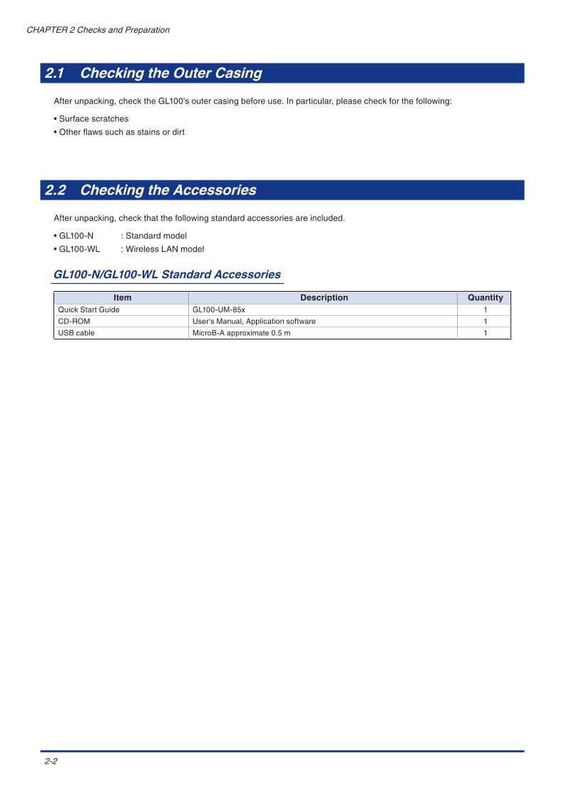
Afterunpacking,checktheGL100'soutercasingbeforeuse.Inparticular,pleasecheckforthefollowing:
•Surfacescratches
•Otherflawssuchasstainsordirt
2.2 Checking the Accessories
Afterunpacking,checkthatthefollowingstandardaccessoriesareincluded.
•GL100-N :Standardmodel
•GL100-WL :WirelessLANmodel
GL100-N/GL100-WL Standard Accessories
Item Description QuantityQuickStartGuide GL100-UM-85x 1
CD-ROM User'sManual,Applicationsoftware 1
USBcable MicroB-Aapproximate0.5m 1
2-3
CHAPTER2ChecksandPreparation
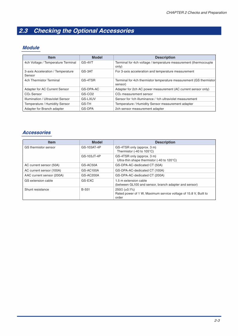
2.3 Checking the Optional Accessories
Module
Item Model Description4chVoltage/TemperatureTerminal GS-4VT Terminalfor4chvoltage/temperaturemeasurement(thermocouple
only)
3-axisAcceleration/TemperatureSensor
GS-3AT For3-axisaccelerationandtemperaturemeasurement
4chThermistorTerminal GS-4TSR Terminalfor4chthermistortemperaturemeasurement(GSthermistorsensor)
AdapterforACCurrentSensor GS-DPA-AC Adapterfor2chACpowermeasurement(ACcurrentsensoronly)
CO2Sensor GS-CO2 CO2measurementsensor
Illumination/UltravioletSensor GS-LXUV Sensorfor1chilluminance/1chultravioletmeasurement
Temperature/HumiditySensor GS-TH Temperature/HumiditySensormeasurementadapter
AdapterforBranchadapter GS-DPA 2chsensormeasurementadapter
Accessories
Item Model DescriptionGSthermistorsensor GS-103AT-4P GS-4TSRonly(approx.3m)
Thermistor(-40to105°C)
GS-103JT-4P GS-4TSRonly(approx.3m)Ultra-thinshapethermistor(-40to120°C)
ACcurrentsensor(50A) GS-AC50A GS-DPA-AC-dedicatedCT(50A)
ACcurrentsensor(100A) GS-AC100A GS-DPA-AC-dedicatedCT(100A)
AACcurrentsensor(200A) GS-AC200A GS-DPA-AC-dedicatedCT(200A)
GSextensioncable GS-EXC 1.5mextensioncable(betweenGL100andsensor,branchadapterandsensor)
Shuntresistance B-551 250Ω(±0.1%)Ratedpowerof1W,Maximumservicevoltageof15.8V,Builttoorder

2-4
CHAPTER2ChecksandPreparation
2.4 Nomenclature and Functions
GL100-N/GL100-WL
FunctionsoftheGL100-NandGL100-WL(withwirelessLANfunction)arenotsame.
Useitafterconfirmingthemodelnameontherearnameplate.
3.Moduleconnectionterminal2.Operationkey1.Monitor
Withinconnectorcover
4.microSDslot
5.USBI/Fterminal
6.Alarmoutputterminal
9.Hookbracket
7.Batterycover
10.Connectorcover
8.Mountingscrewholes
1.Monitor......................................... Thesettingsandmeasuredvaluesaredisplayed.
2.Operationkey............................... Keyoperationisperformedonthescreen.
•MENUkey : Informationabout themeasurementconditionsettingsand thismoduleisdisplayed.
• key :Usedtoselectwhenoperatingthemenu.
•ENTERkey :Usedtoconfirmwhenoperatingthemenu.
•QUITkey :Usedtoreturnto thepreviousscreenordisplaythefree-runningscreenwhensettingthemenu.
•START/STOPkey :Usedtostart/stopthemeasurement.
•STATUSlamp :Themeasurementinformationofthismoduleisdisplayedinorange.
•POWERlamp :Thepowersupplystatusisdisplayedingreen.
QUIT MENU
STATUS
POWER
ENTER
STARTSTOP
3.Moduleconnectionterminal........Usedtoconnecttovariousmeasurementmodule.
4.microSDslot................................UsedtoinsertmicroSDcard.
5.USBI/Fterminal..........................UsedtocommunicateandpowersupplywithUSBcable.
6.Alarmoutputterminal..................Alarmsignalisoutputfromthisterminal.
7.Batterycover................................TwoAAalkalinebatteriesarehousedinthebatterycover.
8.Mountingscrewholes..................ThesizeofthemountingscrewholesisM4×L5.
9.Hookbracket................................Ametalfixingthatsuspendsandsecurestheproduct.
10.Connectorcover.........................Thisisthecoverforeachconnector.
The module connection terminal is used for the sensor and module sold separately. Do not connect the
sensor and module other than them. The GL100 may be damaged.

2-5
CHAPTER2ChecksandPreparation
Descriptions of Screen Display
Initial Screen
Thefollowingscreenisdisplayedafterinitializing.
+0.01V L:OFF +0.10V L:OFF +0.50V L:OFF +1.00V L:OFFBAT LAN SD S: 1.0s
STOP ALM. 1:28
1.Datarecordingstatusdisplay
STOP :RecordingstopppedARMED :AwaitingrecordingstartREC :Recording
8.Measuredvaluedisplay
4.Batteryreplacementdisplay
2.Alarmdisplay3.Currenttime
9.Logicetc.settingsdisplay
7.Samplinginterval
5.LAN:displayedwhenthewirelessLANconnectionisenabled.
6.DisplayedonlywhenaccessingSDcard
Descriptions of Setting Screen
Pressing[MENU]keygoestosettingmenumode.
Pressthe and operationkeystomovethecursor.Theitemthecursorisoncanbechanged.
1.Settingmodedisplay
3.SettingsDisplay
(e.g.1/10:page1of10)Pressthe[MENU]keyorusethe and keystochangethepage.
2.Settingmodepagedisplay
Pressthe[ENTER]keytodisplaythesettingscreenfortheitemwith displayed(e.g.TEMP )
4.Settingitems
Note:Thecurrenttimedisplaycanbeswitchedtotheelapsedtimewiththe[QUIT]keywhenrecording.

2-6
CHAPTER2ChecksandPreparation
2.5 Various Connections
<Power-on>: (Refer to “ 3.2 Power-on.)
1) Supply the power.
2) The GL100 is ready for operation by holding down [MENU] key.
3) Connect the module.
The following screen is displayed. Perform the procedure below.
Module Connection Terminal
Connectthemodule(sensor,terminal,andadapter,etc.)soldseparatelytothemoduleconnectionterminal.
Whenthemodule isnotconnected, the"Sensorerror!!"appearsandthesettingscreen isnotdisplayed.BesuretoconnectthemoduletobeusedbeforeoperatingtheGL100.
Please perform the following procedure to replace the module when the power is supplied.
+0.00V L:OFF +0.00V L:OFF +0.00V L:OFF +0.00V L:OFFBAT LAN SD S:30.0s
STOP ALM. 1:28
GL100-**
Sleeping!! ENTER key to start
QUIT key to Power OffBAT LAN
GL100-XXX Initializing!!
QUIT
STATUS
POWER
ENTER
MENU
STARTSTOP
Free-runningscreen
Holddown[QUIT]keytodisplaythe“Sleeping!!”.
Evenwhenthe“Sleeping!!”isdisplayed,themodulecanbereplaced.
Whilethe“Initializing”isexecuted,pleasedonotoperateanything.
SwitchestoPowerOFFmode.
[QUIT]key ThePowerOFFmodeisusedtosavethebatterypowerwhentheGL100isnotoperated.InthePowerOFFmode,thebatterylifeisapprox.5months.WhentheGL100isinPowerOFFmode(temperature25°C,newbatteries),theGL100switchestostandbystatebyholdingdownthe[MENU]key.
Standbystate

2-7
CHAPTER2ChecksandPreparation
microSD
ToinsertorremovethemicroSD,followtheprocedurebelow.
microSD
microSDslot
GentlypushthemicroSDcardintotheslotuntilitislocked.*Makesuretoinsertthecardtherightway.
WhenejectingthemicroSDcard,pushitingently,thenremovethecard.
• When mounting, the STATUS lamp will turn on while it checks the amount of available space. Please wait
until it turns off.
• When the microSD is inserted, the data free space is checked even in free-running, therefore The SD
display and STATUS lamp are lit for a moment.
USB I/F
TheUSBI/FisusedtosupplytheexternalpowertotheGL100-N/GL100-WLandcommunicateandcontrolthedata.
Forthepowersupplycapacity,refertothesection“PowerSupplyConnection”.
Alarm Output Terminal
Specification:Photo-couplerinsulationswitchingtype
Rating:30V,50mA(powerdissipation150mW)
GL100side
Alarmoutput
Insertthecablewhilepressinghere.
Withinconnectorcover
*CAUTIONWhenpressingherewithaflatscrewdriver,pleasepressthetipofthedriversoasnottobedeeperthantheconnectorsurface.Iftheconnectorispressedtoomuch,itwillbedamaged.
Low-voltage
High-voltage

2-8
CHAPTER2ChecksandPreparation
2.6 Various Modules
4ch Voltage / Temperature Terminal (GS-4VT): Optional
Thissectiondescribesthenameandfunctionofeachpart.
1.Hookportion
2.Inputterminal
3.Logicinputterminal
4.Connector
5.Cablepacking
1. Hookportion......................... Usedtomounttoawall.
2. Inputterminal....................... Usedtoconnectvoltageinputorthermocouple.
3. Logicinputterminal.............. Usedtoapplylogicinput.
4. Connector............................. UsedtoconnecttotheconnectorontheGL100module.
5. Cablepacking...................... Thispackingisusedwhenconnectingtheconnector.
This module is not dustproof or waterproof. Please use it in a proper usage environment.
After connecting the GL100 to modules or sensors, please always check/set the time and date.
< Extension cable >
The module can be used approx. 1.5 m away from the GL100 by using an extension cable for GS
(GS-EXC). However, you cannot connect and use multiple extension cables.

2-9
CHAPTER2ChecksandPreparation
Tip of Each Input Terminal Function
1. Voltage input
Makesuretopayattentiontothe+and–terminalswhenconnectingit.
+......... High-voltageterminal(terminalinputontheinputsignal’shigh-voltageside)
-.......... Low-voltageterminal(terminalinputontheinputsignal’slow-voltageside)
2. Thermocouple input
Connectthermocoupletothe+and–terminals.
Thermocouple
3. Current input
Attachshuntresistancewhenmeasuringthecurrentinput.
ShuntresistanceE.g.:For4-20mA,add250Ω(±0.1%)resistanceand
measurewitha1-5Vrange.
*Forshuntresistance,usetheB-551(option).
4. Logic / pulse input
+......... No.1toNo.4:High-voltageterminal(terminalinputontheinputsignal’shigh-voltageside)
-.......... G:Low-voltageterminal(terminalinputontheinputsignal’slow-voltageside)
Wheninsertingthecable,insertitwhilepressinghere.
• G is the GND terminal for this module.
• For the maximum input voltage, refer to "3 Regarding Maximum Input Voltage."
+3.3V +3.3V
10kΩ
100kΩ
180kΩ
GND
LOGIC/PULSE
Comparator

2-10
CHAPTER2ChecksandPreparation
Notes on temperature measurement
When measuring the temperature, please pay attention to the following.
• Do not block the air vents of the GL100. Leave a clear space of at least 20 cm around it.
• To measure stably the temperature, please warm up for 30 minutes or more after power-on.
• When rapid temperature change occurs in the input terminals, the error may occur on the measurement.
• When the measurement is performed in noisy place, be sure to connect to the ground through the GND terminal.
Regarding Maximum Input Voltage
Toavoidbreak-downsorshort-circuitingaccidents,pleasemakesuretoabidebytheitemswrittenbelow.
Incasetheinputvoltageexceedsthespecifications,thecircuitattheinputpartwillbreakdown.Pleasedon'tinputit.
<Inputterminal(+)/Inputterminal(-)interval>Maximuminputvoltage:DC60Vp-p
<Inputterminal(-)/Inputterminal(-)interval>Maximuminputvoltage:60Vp-p
<Inputterminal(-)/GNDterminalinterval>Maximuminputvoltage:DC60Vp-pWithstandvoltage:350Vp-p/1min.
Logic/Pulse<Inputterminal(+)/GNDterminalinterval>Maximuminputvoltage:DC24V
• For thedisplayscreenwhenmaximum inputvoltage isapplied, ifavoltageexceeding10%of fullscale for the
measurementrangeisinput,the“+++++”isdisplayedforpositivedirection,orthe”-----”isdisplayedfornegative
direction.

2-11
CHAPTER 2 Checks and Preparation
3-axis Acceleration / Temperature Sensor (GS-3AT): Optional
This section describes the name and function of each part.
1. Sensor unit
3. Connector
4. Cable packing
2. Sensor mounting holes
1. Sensor unit ........................... The 3-axis acceleration and temperature sensor are built in this module.
2. Sensor mounting hole .......... Used to fix the sensor.
3. Connector ............................. Used to connect to the connector on the GL100 module.
4. Cable packing ...................... This packing is used when connecting the connector.
• This sensor unit is dustproof and splash-resistant to IP54 standards. It can be used in the same
conditions as the module.
• Please take care not to drop or shock the sensor.
• The data during recording will be erased if the power is not supplied to the module in the event of a power
outage or battery exhaustion while recording in Memory mode with the 3-axis Acceleration / Temperature
Sensor (GS-3AT).
After connecting the GL100 to modules or sensors, please always check/set the time and date.
< Extension cable >
The module can be used approx. 1.5 m away from the GL100 by using an extension cable for GS (GS-
EXC). However, you cannot connect and use multiple extension cables.

2-12
CHAPTER2ChecksandPreparation
Tip of the Sensor Mounting
Checktheoperatingdirectionofthesensorunit,thensecurelymountitusingfourM3screwstowhatistobemeasured.
1. Connecting to the module
Whenconnecting thismodule,youcanalsouse theGSextensioncable (GS-EXC;soldseparately) formore
convenientconnection.
Objecttobemeasured
If the sensor’s mounting is loose, it will give inaccurate readings.
3644 4.551 19.5
44 51
Sensorunitmountingdimensions(Unit:approx.mm)
< Extension cable >
The module can be used approx. 1.5 m away from the GL100 by using an extension cable for GS
(GS-EXC). However, you cannot connect and use multiple extension cables.
Thereare±2G,±5G,and±10G,or±20m/s2,±50m/s2,and±100m/s2intheaccelerationrange.
However,thegravitationalaccelerationis1G=Approx.9.807m/s2.

2-13
CHAPTER2ChecksandPreparation
4ch Thermistor Terminal (GS-4TSR): Optional
Thissectiondescribesthenameandfunctionofeachpart.
1.Hookportion
2.Inputterminal
3.Logic/Pulse inputterminal
4.Connector
5.Cablepacking
1. Hookportion......................... Usedtomounttoawall.
2. Inputterminal....................... UsedtoconnectThermistor.
3. Logic/Pulse
inputterminal.................. Usedtoinputlogic/pulse.
4. Connector............................. UsedtoconnecttotheconnectorontheGL100module.
5. Cablepacking...................... Thispackingisusedwhenconnectingtheconnector.
The GL100 is not waterproof and dustproof. Please use it in a proper usage environment.
After connecting the GL100 to modules or sensors, please always check/set the time and date.
< Extension cable >
The module can be used approx. 1.5 m away from the GL100 by using an extension cable for GS
(GS-EXC). However, you cannot connect and use multiple extension cables.

2-14
CHAPTER2ChecksandPreparation
Tip of Each Input Terminal Function
1. Thermistor input
ConnecttheGSthermistorsensor(GS-103AT-4PorGS-103JT-4P;eachsoldseparately)tothe+/-.
Model:GS-103AT-4P
Model:GS-103JT-4P(Ultra-thinshape)
This terminal is for thermistor input only. Make sure not to input voltage or electric current, as this can
cause damage.
2. Logic / pulse input
ConnectGSthermistorsensor(GS-103AT-4PorGS-103JT-4P)soldseparatelytothe+and–terminals.
+......... No.1toNo.4:High-voltageterminal(terminalinputontheinputsignal’shigh-voltageside)
-.......... G:Low-voltageterminal(terminalinputontheinputsignal’slow-voltageside)
Wheninsertingthecable,insertitwhilepressinghere.
G is the GND terminal for this module.
For the circuit configuration, please refer to “ Tip of each input terminal function” in “4ch voltage /
temperature terminal (GS-4VT)” described above.

2-15
CHAPTER2ChecksandPreparation
Regarding Maximum Input Voltage
Toavoidbreak-downsorshort-circuitingaccidents,pleasemakesuretoabidebytheitemswrittenbelow.
Incasetheinputvoltageexceedsthespecifications,thecircuitattheinputpartwillbreakdown.Pleasedon'tinputit.
Logic/Pulse<Inputterminal(+)/GNDterminalinterval>Maximuminputvoltage:DC24V

2-16
CHAPTER2ChecksandPreparation
Adapter for AC Current Sensor (GS-DPA-AC): Optional
Thissectiondescribesthenameandfunctionofeachpart.
1.Hookportion
2.Inputtermi
3.Connector
4.Cablepacking
1. Hookportion......................... Usedtomounttoawall.
2. Inputterminal....................... TerminalthatconnectstotheACCurrentSensor(soldseparately).
3. Connector............................. UsedtoconnecttotheconnectorontheGL100module
4. Cablepacking...................... Thispackingisusedwhenconnectingtheconnector.
After connecting the GL100 to modules or sensors, please always check/set the time and date.
< Extension cable >
The module can be used approx. 1.5 m away from the GL100 by using an extension cable for GS
(GS-EXC). However, you cannot connect and use multiple extension cables.

2-17
CHAPTER2ChecksandPreparation
Tip of the sensor mounting
1. Connect the AC Current Sensor (GS-AC**A, sold separately) (1) Recording to the module.
Connecting :Pushtheconnectorinuntilitlocksin.
Disconnecting :Pulltheconnectoroutwhilepressingdownonthelockonthebottomwithyourfinger.
K=>L
K=>LConnectorcable
ACCurrentSensor
The connector is exclusively to be used to connect the AC Current Sensor. Do not connect it to voltages,
other electrical currents, etc. It will damage the module.
Pulling the AC Current Sensor’s cable and holding the sensor by the cable will damage the cable’s wires.
2. How to measure with AC Current Sensor
RemovetheACCurrentSensor’slock,insertthemeasurementcableandpushitinuntilitlocks(puttingthecablein
thewrongwaywillcausethemoduletomeasureincorrectly).
K=>LK=>L
Unlock Insertthecableandpushitinuntilitclicks.
Loadside(L)
Powerside(K)
Clamp ch1 or ch2 to L-phase when using single-phase 2-wire
Clamp ch1 and ch2 to R-phase and S-phase respectively when using single-phase 3-wire.
Clamp ch1 and ch2 to R-phase and T-phase respectively when using 3-phase 3-wire.
K=
>L
K=
>L
SR T
K=
>L
K=
>L
NR
K=
>L
NL S
Loadside(L)
Powerside(K)
Loadside(L)
Powerside(K)
Loadside(L)
Powerside(K)
<Single-phase2-wire> <Single-phase3-wire> <3-phase3-wire>
Exampleofwiring
*Itmaybedamagedwhenliftingmorethannecessarythehook,sopleaseusecaution.

2-18
CHAPTER2ChecksandPreparation
Tip of Settings
1. Various settings
InAMPsettingscreen,select themeasurementmode.Nextselect thesensor type tobeusedand thenset the
measurementvoltageandpowerfactor.
MEAS. Mode
AC1 2W(2ch)
Input Off,50,100,200A
DC-V 90to264V
Powerfactor 0.30to1.00
AC1 3W,AC3 3W
Input 50,100,200A
DC-V 90to264V
Powerfactor 0.30to1.00
Input: : BesuretomatchtotheACcurrentsensortypetobeused.
DC-V : Settheeffectivevoltagetobemeasured.Sinceitisusedtointernallyconvertthecurrentvalue,besuretosettothecorrectvalue.
Powerfactor : Specifythepowerfactortobemeasured.
Thepowerfactorisratioofactivepowerto(apparent)power,dependsonthemeasuringobject.
Since thepower factor isused to internallyconvert thecurrentvalue to thepowervalue, it is required toadjust
accordingtothemeasuringobject.
Formula used internally
Actuallythecurrentvalueismeasured.ThepowervalueisconvertedbymultiplyingtheAMPsettingvoltagebythe
currentvaluemeasuredwiththepowerfactor(ratioofactivepower).(Seethefollowingformula.)
AC1 2W : Measurementsettingwhensingle-phase2-wireisused
2chmeasurementispossible.
*Power=MeasuredcurrentxVoltagexPowerfactor
AC1 3W : Measurementsettingwhensingle-phase3-wireisused
*Power=(Measuredcurrent(ch1)+Measuredcurrent(ch2))xVoltagexPowerfactor
AC3 3W : Measurementsettingwhenthree-phase3-wireisused
*Power=((Measuredcurrent(ch1)+Measuredcurrent(ch2))÷2)xVoltagex√3xPowerfactor
2-19
CHAPTER2ChecksandPreparation
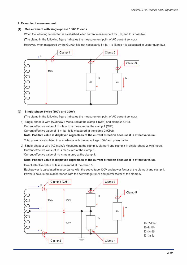
2. Example of measurement
(1) Measurement with single-phase 100V, 2 loads
Whenthefollowingconnectionisestablished,eachcurrentmeasurementforI,Ia,andIbispossible.
(TheclampinthefollowingfigureindicatesthemeasurementpointofACcurrentsensor.)
However,whenmeasuredbytheGL100,itisnotnecessarilyI=Ia+Ib(Sinceitiscalculatedinvectorquantity.).
Ib
100V
I
IaZaZb
Clamp 1 Clamp 2
Clamp 3
(2) Single-phase 3-wire (100V and 200V)
(TheclampinthefollowingfigureindicatesthemeasurementpointofACcurrentsensor.)
1) Single-phase3-wire(AC1 3W):Measuredattheclamp1(CH1)andclamp2(CH2).
CurrenteffectivevalueofI1=Ia+Ibismeasuredattheclamp1(CH1).
CurrenteffectivevalueofI3=-Ia-Icismeasuredattheclamp2(CH2).
Note: Positive value is displayed regardless of the current direction because it is effective value.
Totalpoweriscalculatedinaccordancewiththesetvoltage100Vandpowerfactor.
2) Single-phase2-wire(AC1 2W):Measuredattheclamp3,clamp4andclamp5insingle-phase2-wiremode.
CurrenteffectivevalueofIbismeasuredattheclamp3.
Currenteffectivevalueof-Icismeasuredattheclamp4.
Note: Positive value is displayed regardless of the current direction because it is effective value.
CrrenteffectivevalueofIaismeasuredattheclamp5.
Eachpoweriscalculatedinaccordancewiththesetvoltage100Vandpowerfactorattheclamp3andclamp4.
Poweriscalculatedinaccordancewiththesetvoltage200Vandpowerfactorattheclamp5.
200V
I1
I2 IaZa
Ib
Ic
I3
100V
100V
Clamp 1 (CH1) Clamp 3
Clamp 4Clamp 2
Clamp 5
I1-I2-I3=0I1=Ia+IbI2=Ic-IbI3=Ia-Ic
2-20
CHAPTER2ChecksandPreparation
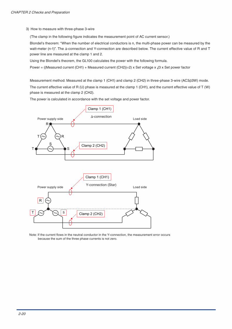
3) Howtomeasurewiththree-phase3-wire
(TheclampinthefollowingfigureindicatesthemeasurementpointofACcurrentsensor.)
Blondel'stheorem:“Whenthenumberofelectricalconductorsisn,themulti-phasepowercanbemeasuredbythe
watt-meter(n-1)”.TheΔ-connectionandY-connectionaredescribedbelow.ThecurrenteffectivevalueofRandT
powerlinearemeasuredattheclamp1and2.
UsingtheBlondel'stheorem,theGL100calculatesthepowerwiththefollowingformula.
Power=((Measuredcurrent(CH1)+Measuredcurrent(CH2))÷2)xSetvoltagex√3xSetpowerfactor
Measurementmethod:Measuredattheclamp1(CH1)andclamp2(CH2)inthree-phase3-wire(AC3 3W)mode.
ThecurrenteffectivevalueofR(U)phaseismeasuredattheclamp1(CH1),andthecurrenteffectivevalueofT(W)
phaseismeasuredattheclamp2(CH2).
Thepoweriscalculatedinaccordancewiththesetvoltageandpowerfactor.
Clamp 1 (CH1)
T
T S
R
S
R
Clamp 2 (CH2)
Δ-connectionPowersupplyside Loadside
Clamp 1 (CH1)
T
R
S Clamp 2 (CH2)
Powersupplyside LoadsideY-connection(Star)
Note:IfthecurrentflowsintheneutralconductorintheY-connection,themeasurementerroroccursbecausethesumofthethreephasecurrentsisnotzero.

2-21
CHAPTER2ChecksandPreparation
(3) Display screen
Indisplayscreen
•Theinstantaneouspoweronlyisdisplayedduringfree-running.
Accumulated Value
Duringrecording,youcanswitchtotheaccumulationscreenbyoperating[ ]and[ ]keys.
1.AC(A):105.08A PWR. 10.51kwh2.AC(A):105.08A PWR. 10.51kwhBAT LAN SD S: 1.0s
STOP ALM. 1:28
Accumulatedvaluedisplay
1.AC(A): 105.08A PWR. 10.51kw2.AC(A): 105.08A PWR. 10.51kwBAT LAN SD S: 1.0s
REC. ALM. 1:28
Normaldisplay
Howtocleartheaccumulatedvalue
Tocleartheaccumulatedvalue,followthefollowingprocedure.
•Whenyoustart,theaccumulatedvalueisclearedandtheaccumulationoperationisperformed.
Theaccumulationoperationisperformedevenintriggerwaitingstate.

2-22
CHAPTER2ChecksandPreparation
Illumination / Ultraviolet Sensor (GS-LXUV): Optional
Thissectiondescribesthenameandfunctionofeachpart.
1.Hookportion
2.Illuminationsensor
3.Ultravioletsensor
4.Connector
5.Cablepacking
1. Hookportion......................... Usedtomounttoawall.
2. Illuminationsensor............... Sensorunitthatmeasuresilluminationrays.
3. Ultravioletsensor................. Sensorunitthatmeasuresultravioletrays.
4. Connector............................. UsedtoconnecttotheconnectorontheGL100module.
5. Cablepacking...................... Thispackingisusedwhenconnectingtheconnector.
• When measuring ultraviolet rays that have an effect on the eyes or the skin, wear protective glasses,
apply light shielding, etc.
• If the sensor unit becomes dirty, this may affect measurements. Wipe it down with a soft cloth.
• Make sure to handle the sensor unit in a way that it will not crack. If the sensor unit is cracked it may
affect easurements. Replace the sensor if cracked.
After connecting the GL100 to modules or sensors, please always check/set the time and date.
< Extension cable >
The module can be used approx. 1.5 m away from the GL100 by using an extension cable for GS
(GS-EXC). However, you cannot connect and use multiple extension cables.

2-23
CHAPTER2ChecksandPreparation
Tip of measurement
Theilluminationwavelengthis560nmandthepeakofspectralsensitivityisUVwavelength370nm.
1.0 1.0
400 560 750 (nm) 260 370 400 (nm)
<SpectralSensitivityCharacteristic>
Illumination Ultraviolet
Spectralsensitivity Spectralsensitivity
Wavelength Wavelength
Accumulated Value
Duringrecording,youcanswitchtotheaccumulationscreenbyoperating[ ]and[ ]keys.
AccumulatedvaluedisplayNormaldisplay
How to clear the accumulated value
Tocleartheaccumulatedvalue,followthefollowingprocedure.
•Whenyoustart,theaccumulatedvalueisclearedandtheaccumulationoperationisperformed.
Theaccumulationoperationisperformedevenintriggerwaitingstate.

2-24
CHAPTER2ChecksandPreparation
CO2 Sensor (GS-CO2): Optional
Thissectiondescribesthenameandfunctionofeachpart.
1.Hookportion
2.Internalsensor
3.Connector
4.Cablepacking
1. Hookportion......................... Usedtomounttoawall.
2. Internalsensor..................... ThereisaninternalsensorthatdetectstheCO2.
Thelampfordetectingflasheseverytwoseconds.
3. Connector............................. UsedtoconnecttotheconnectorontheGL100module.
4. Cablepacking...................... Thispackingisusedwhenconnectingtheconnector.
• The battery is not available for power supply. Use the USB cable to supply the power.
• Do not use the module close to your face.
Your breath may affect measurements.
• Blocking the module’s aperture may cause the airflow to affect measurements.
After connecting the GL100 to modules or sensors, please always check/set the time and date.
< Extension cable >
The module can be used approx. 1.5 m away from the GL100 by using an extension cable for GS
(GS-EXC). However, you cannot connect and use multiple extension cables.

2-25
CHAPTER2ChecksandPreparation
Temperature / Humidity Sensor (GS-TH): Optional
Thissectiondescribesthenameandfunctionofeachpart.
1.Hookportion
2.Connector
3.Cablepacking
1. Hookportion......................... Usedtomounttoawall.
2. Connector............................. UsedtoconnecttotheconnectorontheGL100module.
3. Cablepacking...................... Thispackingisusedwhenconnectingtheconnector.
Attaching just this module to the wall, etc. will damage the connector cable. Always connect to the GL100.
Wallmountinghook
The temperature sensor measures the change in capacitance of the conductivity caused by moisture
absorption. Therefore, dust, fumes and other organic compound may affect measurements. Usage in
an environment with a large quantity of these substances floating about will cause large measurement
deviations.
After connecting the GL100 to modules or sensors, please always check/set the time and date.
< Extension cable >
The module can be used approx. 1.5 m away from the GL100 by using an extension cable for GS
(GS-EXC). However, you cannot connect and use multiple extension cables.

2-26
CHAPTER2ChecksandPreparation
Accumulated Value
Duringrecording,youcanswitchtotheaccumulationscreenbyoperating[ ]and[ ]keys.
AccumulatedvaluedisplayNormaldisplay
How to clear the accumulated value
Tocleartheaccumulatedvalue,followthefollowingprocedure.
•Whenyoustart,theaccumulatedvalueisclearedandtheaccumulationoperationisperformed.
Theaccumulationoperationisperformedevenintriggerwaitingstate.
2-27
CHAPTER2ChecksandPreparation
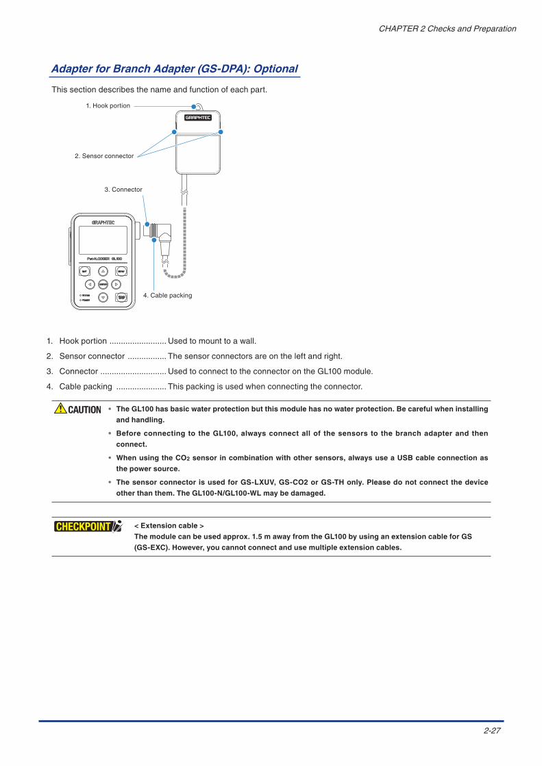
Adapter for Branch Adapter (GS-DPA): Optional
Thissectiondescribesthenameandfunctionofeachpart.
1.Hookportion
2.Sensorconnector
3.Connector
4.Cablepacking
1. Hookportion......................... Usedtomounttoawall.
2. Sensorconnector................. Thesensorconnectorsareontheleftandright.
3. Connector............................. UsedtoconnecttotheconnectorontheGL100module.
4. Cablepacking...................... Thispackingisusedwhenconnectingtheconnector.
• The GL100 has basic water protection but this module has no water protection. Be careful when installing
and handling.
• Before connecting to the GL100, always connect all of the sensors to the branch adapter and then
connect.
• When using the CO2 sensor in combination with other sensors, always use a USB cable connection as
the power source.
• The sensor connector is used for GS-LXUV, GS-CO2 or GS-TH only. Please do not connect the device
other than them. The GL100-N/GL100-WL may be damaged.
< Extension cable >
The module can be used approx. 1.5 m away from the GL100 by using an extension cable for GS
(GS-EXC). However, you cannot connect and use multiple extension cables.

2-28
CHAPTER2ChecksandPreparation
Tip of the sensor combination.
It is not possible to be used by connecting two same sensors.
< Extension cable >
The module can be used approx. 1.5 m away from the GL100 by using an extension cable for GS
(GS-EXC). However, you cannot connect and use multiple extension cables.
Therearethefollowingthreesensorcombinations.
1. Combined illumination / ultraviolet sensor and temperature and humidity sensor measurement
Compositemeasurementcanbedonebyusingtheillumination/ultravioletsensor(GS-LXUV)andthetemperature
andhumiditysensor(GS-TH)(eachsoldseparately).
GL100mainmodule
Temperatureandhumiditysensor(GS-TH)
Illumination/Ultravioletsensor(GS-LXUV)
BranchadapterforGS(GS-DPA)

2-29
CHAPTER2ChecksandPreparation
2. Combined CO2 sensor and temperature and humidity sensor measurement
Compositemeasurementcanbedonebyusing theCO2sensor (GS-CO2)and the temperatureandhumidity
sensor(GS-TH)(eachsoldseparately).
If the CO2 sensor (GS-CO2) is included in the assembly, it cannot be powered with batteries.
* TheGL100’spowerisprovidedthroughaUSBcableconnection
GL100mainmodule
Temperatureandhumiditysensor(GS-TH)
CO2Sensor(GS-CO2)
BranchadapterforGS(GS-DPA)

2-30
CHAPTER2ChecksandPreparation
3. Combined CO2 sensor and illumination / ultraviolet sensor
CompositemeasurementcanbedonebyusingtheCO2sensor(GS-CO2)andtheillumination/ultravioletsensor
(GS-LXUV)(eachsoldseparately).
If the CO2 sensor (GS-CO2) is included in the assembly, it cannot be powered with batteries.
* TheGl100’spowerisprovidedthroughaUSBcableconnection.
GL100mainmodule
Illumination/Ultravioletsensor(GS-LXUV)
CO2Sensor(GS-CO2)
BranchadapterforGS(GS-DPA)

2-31
CHAPTER2ChecksandPreparation
Accumulated Value
Byswitchingthedisplayeddata,therecordeddatacanbedisplayedindetailduringdatarecording.
1. Combined measurement of the iIllumination / ultraviolet sensor and temperature and humidity sensor
Indisplayscreen,twomeasurementsofillumination/ultravioletsensorandtemperatureandhumiditysensorare
displayed.
Duringrecording,youcanswitchtotheaccumulationscreenbyoperating[ ]and[ ]keys.
Accumulatedvaluedisplaybypressingonce
Normaldisplay Accumulatedvaluedisplaybypressingtwice
2. Combined measurement of the CO2 sensor and temperature and humidity sensor
Indisplayscreen,twomeasurementsofCO2sensorandtemperatureandhumiditysensoraredisplayed.
Duringrecording,youcanswitchtotheaccumulationscreenbyoperating[ ]and[ ]keys.
AccumulatedvaluedisplayNormaldisplay
3. Combined measurement of the CO2 sensor and iIllumination / ultraviolet sensor
Indisplayscreen,twomeasurementsofCO2sensorandillumination/ultravioletsensoraredisplayed.
Duringrecording,youcanswitchtotheaccumulationscreenbyoperating[ ]and[ ]keys.
AccumulatedvaluedisplayNormaldisplay
Howtocleartheaccumulatedvalue
Tocleartheaccumulatedvalue,followthefollowingprocedure.
•Whenyoustart,theaccumulatedvalueisclearedandtheaccumulationoperationisperformed.
Theaccumulationoperationisperformedevenintriggerwaitingstate.

3-1
CHAPTER3MeasureandSet
CHAPTER 3 Measure and SetThischapterexplainshowtocheckthemainmodule'sexternalcasingandaccessories,andhowtopreparethemainmoduleforoperation.
Product Summary
3.1 Before Setting Up3.2 Power-on3.3 Date/Time Adjustment3.4 Measurement Procedure

3-2
CHAPTER3MeasureandSet
3.1 Before Setting Up
WhenyouconnectthemoduleandpowersupplytotheGL100,variousscreendisplayandoperationarepossible.
First,setthedate/timeandlanguage(English/Japanese)andthensetupvarioussettings.
1)Power-on : Referto“3.2Power-on”.
2)Settingdate : Whenthepowerisconsumed,thesetvaluesreturnstothedefaultvalues.Besuretosetthemin
accordancewith“3.3Date/TimeAdjustment”.
3)Settinglanguag: Thedefaultdisplay language isEnglish.Toswitch thedisplay languagetoJapanese,refer to”
SettingLanguage”in“3.4MeasurementProcedure”.
3-3
CHAPTER3MeasureandSet
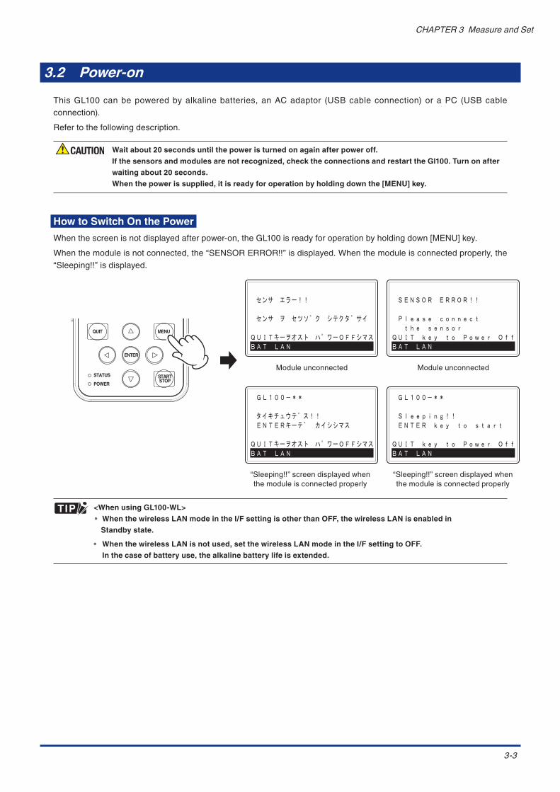
3.2 Power-on
ThisGL100canbepoweredbyalkalinebatteries,anACadaptor (USBcableconnection)oraPC (USBcableconnection).
Refertothefollowingdescription.
Wait about 20 seconds until the power is turned on again after power off.
If the sensors and modules are not recognized, check the connections and restart the Gl100. Turn on after
waiting about 20 seconds.
When the power is supplied, it is ready for operation by holding down the [MENU] key.
How to Switch On the Power
Whenthescreenisnotdisplayedafterpower-on,theGL100isreadyforoperationbyholdingdown[MENU]key.
Whenthemoduleisnotconnected,the“SENSORERROR!!”isdisplayed.Whenthemoduleisconnectedproperly,the“Sleeping!!”isdisplayed.
QUIT
STATUS
POWER
ENTER
MENU
STARTSTOP
“Sleeping!!”screendisplayedwhenthemoduleisconnectedproperly
Moduleunconnected
センサ エラー!!
センサ ヲ セツソ゛ク シテクタ゛サイ
QUITキーヲオスト ハ゜ワーOFFシマスBAT LAN
GL100-**
タイキチュウテ゛ス!! ENTERキーテ゛ カイシシマス
QUITキーヲオスト ハ゜ワーOFFシマスBAT LAN
“Sleeping!!”screendisplayedwhenthemoduleisconnectedproperly
Moduleunconnected
SENSOR ERROR!!
Please connect the sensor QUIT key to Power OffBAT LAN
GL100-**
Sleeping!! ENTER key to start
QUIT key to Power OffBAT LAN
<When using GL100-WL>
• When the wireless LAN mode in the I/F setting is other than OFF, the wireless LAN is enabled in
Standby state.
• When the wireless LAN is not used, set the wireless LAN mode in the I/F setting to OFF.
In the case of battery use, the alkaline battery life is extended.

3-4
CHAPTER3MeasureandSet
How to Switch to Power OFF Mode
Toswitchtothismodewhilethe“Sleeping!!”screenisdisplayed,press[QUIT]key.
(Thisscreenisdisplayedwhenthepowerissuppliedandthemoduleisconnected.)
GL100-**
Sleeping!! ENTER key to start
QUIT key to Power OffBAT LAN
QUIT
STATUS
POWER
ENTER
MENU
STARTSTOP
Standbystate
Press[QUIT]key.
PowerOFFMode
Inthiscase,thereisnothingdisplayedinthisscreen.
TheGL100isreadyforoperationandthe“Sleeping!!”screenaboveisdisplayedbyholdingdown[MENU]key.
• WhenBAT(LowBatteryStatus)isdisplayedinthebottomleftcorneroftheLCDscreen,itisnotpossibletoproceed
tothenextscreenforthebatteryshortage.
Press[QUIT]keytoswitchtoPowerOFFModeandreplacethebattery.
• WhenBAT(LowBatteryStatus)andLANconnectingstateisdisplayedinthebottomleftcorneroftheLCDscreen,it
isnotpossibletoproceedtothenextscreenforthebatteryshortage.
Press[QUIT]keytoswitchtoPowerOFFModeandreplacethebattery. Inthiscase,sincetheLANconnection is
disabled,re-connecttotheLANafterreplacingthebattery.
There is no screen display while the screen saver is running, but the Power lamp (green) flashes. In such
cases, the screen is displayed by pressing any key.
When the Power lamp (green) does not flash, the GL100 is in Power OFF state. In such cases, hold down
[MENU] key.
<Power OFF Mode>
By switching to the Power OFF Mode, the battery life is extended when not in use.
New alkaline battery life is about 5 months. (at 25°C).

3-5
CHAPTER3MeasureandSet
1. How to install the batteries
(1) Loosenthescrewsonthebackcover.
Screw
(2)Removethebackcover.
(3)InserttwoAAalkalinebatteries.
*Makesuretoinsertthebatteriestherightway.
(4)Attachthebackcoverandtightenthescrews.
Screw
Make sure to use two size AA alkaline batteries.
Do not use zinc-carbon batteries or nickel hydride (rechargeable) batteries.
3-6
CHAPTER3MeasureandSet
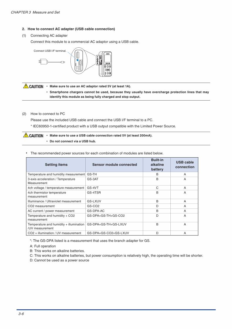
2. How to connect AC adapter (USB cable connection)
(1) ConnectingACadapter
ConnectthismoduletoacommercialACadaptorusingaUSBcable.
ConnectUSBI/Fterminal.
• Make sure to use an AC adaptor rated 5V (at least 1A).
• Smartphone chargers cannot be used, because they usually have overcharge protection lines that may
identify this module as being fully charged and stop output.
(2) HowtoconnecttoPC
PleaseusetheincludedUSBcableandconnecttheUSBI/FterminaltoaPC.
*IEC60950-1-certifiedproductwithaUSBoutputcompatiblewiththeLimitedPowerSource.
• Make sure to use a USB cable connection rated 5V (at least 200mA).
• Do not connect via a USB hub.
• Therecommendedpowersourcesforeachcombinationofmodulesarelistedbelow.
Setting items Sensor module connectedBuilt-inalkaline battery
USB cableconnection
Temperatureandhumiditymeasurement GS-TH B A
3-axisacceleration/TemperatureMeasurement
GS-3AT B A
4chvoltage/temperaturemeasurement GS-4VT C A
4chthermistortemperaturemeasurement
GS-4TSR B A
Illuminance/Ultravioletmeasurement GS-LXUV B A
CO2measurement GS-CO2 D A
ACcurrent/powermeasurement GS-DPA-AC B A
Temperatureandhumidity+CO2measurement
GS-DPA+GS-TH+GS-CO2 D A
Temperatureandhumidity+illumination/UVmeasurement
GS-DPA+GS-TH+GS-LXUV B A
CO2+illumination/UVmeasurement GS-DPA+GS-CO2+GS-LXUV D A
*:TheGS-DPAlistedisameasurementthatusesthebranchadapterforGS.
A:FulloperationB:Thisworksonalkalinebatteries.C:Thisworksonalkalinebatteries,butpowerconsumptionisrelativelyhigh,theoperatingtimewillbeshorter.D:Cannotbeusedasapowersource
3-7
CHAPTER3MeasureandSet
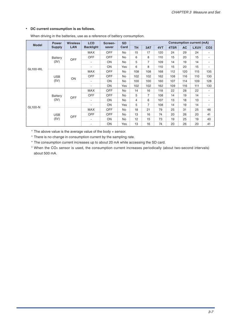
• DC current consumption is as follows.
Whendrivinginthebatteries,useasareferenceofbatteryconsumption.
ModelPower Supply
Wireless LAN
LCD Backlight
Screen-saver
SD Card
Consumption current (mA)
TH 3AT 4VT 4TSR AC LXUV CO2
GL100-WL
Battery(3V)
OFF
MAX OFF No 15 17 120 24 29 24 -
OFF OFF No 6 8 110 15 20 15 -
- ON No 5 7 109 14 19 14 -
- ON Yes 6 8 110 15 20 15 -
USB(5V)
ON
MAX OFF No 108 108 168 112 120 115 135
OFF OFF No 102 102 162 108 116 110 130
- ON No 100 100 160 107 114 109 128
- ON Yes 102 102 162 109 116 111 130
GL100-N
Battery(3V)
OFF
MAX OFF No 14 16 118 22 28 22 -
OFF OFF No 5 7 108 14 19 14 -
- ON No 4 6 107 13 18 13 -
- ON Yes 5 7 108 14 19 14 -
USB(5V)
OFF
MAX OFF No 18 21 79 25 31 25 46
OFF OFF No 13 16 74 20 26 20 41
- ON No 12 15 73 19 25 19 40
- ON Yes 13 16 74 20 26 20 41
*Theabovevalueistheaveragevalueofthebody+sensor.
*Thereisnochangeinconsumptioncurrentbythesamplingrate.
*Theconsumptioncurrentincreasesuptoabout20mAwhileaccessingtheSDcard.
*WhentheCO2sensor isused, theconsumptioncurrent increasesperiodically (about two-second intervals)
about500mA.

3-8
CHAPTER3MeasureandSet
3.3 Date/Time Adjustment
AfterconnectingthemoduleandpowersourcetotheGL100,set thedateandtimeinaccordancewiththefollowingprocedure.
Life of the internal clock back-up battery is about 10 hours.
When the power has been not supplied for a long time, the set date and time are reset. Always check the
date and time after connecting the module. If this date and time is wrong, the data name when recorded is
different from the real time.
• Hold down the [QUIT] key (approx. 3 seconds) to put the module into standby state.
• In the case of battery-powered, put the module into standby state automatically if you do not
operate for 3 minutes.
When the wireless LAN is enabled, the module will not go into standby state.
• Press [ENTER] key in Standby state to return to the free-running screen.
1.Setupthepowersource
2.PreparetheGL100-N/GL100-WLandmodules.
Ifnotconnectingthemodule,itisnotpossibletoset.
3.Performthefollowingprocedure(GL-THisusedinthisprocedure).
1) Beforeconnectingthemodule,thefollowingscreenisdisplayed.
SENSOR ERROR!!
Please connect the sensor QUIT key to Power OffBAT LAN
Moduleunconnectedstate
2)Connectthe(GL-TH)moduletotheGL100-N/GL100-WL.
Thefollowingscreenisdisplayedafterconnectingit.
”Please wait”
Recognitionofmoduletypes
TheGL100-N/GL100-WLisinstandbystateafterrecognizingthemoduletype.
GL100-**
Sleeping!! ENTER key to start
QUIT key to Power OffBAT LAN
Standbystate

3-9
CHAPTER3MeasureandSet
3)Press[ENTER]keytodisplaythefree-runningscreen.
QUIT
STATUS
POWER
ENTER
MENU
STARTSTOP
Thefree-runningscreenisdisplayedafterconfirmingthemoduleconditions.
GL100-XXX Initializing!!
Free-runningscreen
4)Press[MENU]keytodisplaythesettingscreen.
Firstpageofthesettingscreenisdisplayed..
QUIT
STATUS
POWER
ENTER
MENU
STARTSTOP
5)Displaythedateandtimeadjustmentpage(8/10).
Press[ ]keyor[MENU]keyuntilthepageisswitchedtothe“OTHER-1”page.
QUIT
STATUS
POWER
ENTER
MENU
STARTSTOP
Or
QUIT
STATUS
POWER
ENTER
MENU
STARTSTOP

3-10
CHAPTER3MeasureandSet
6)Selectthedisplaymode(Mode).
Press[ ]keyuntilthe“Data/Time”ishighlighted.
QUIT
STATUS
POWER
ENTER
MENU
STARTSTOP
Press[ENTER]keytodisplaythe“Mode”settingscreen.
QUIT
STATUS
POWER
ENTER
MENU
STARTSTOP
Againpress[ENTER]keytoselecttheDisplaymodeusing[ ]or[ ]key.Press[ENTER]keytoconfirmit.
QUIT
STATUS
POWER
ENTER
MENU
STARTSTOP
7)Setthedate.
Press[ ]keytohighlighttheDate.
QUIT
STATUS
POWER
ENTER
MENU
STARTSTOP
Againpress[ENTER]keytodisplaythescreentochangethevalue.

3-11
CHAPTER3MeasureandSet
Press[ ]or[ ]keytoincreaseordecreasethevalue.
ToadjustthevalueofMM:DD,highlightthevaluetobemodifiedbyoperating[ ]or[ ]keyandthenadjustitby
operating[ ]or[ ]key.Press[ENTER]keytoconfirmitaftercompletion.
8)Setthetime.
Press[ ]keytohighlightthe“Time”.
QUIT
STATUS
POWER
ENTER
MENU
STARTSTOP
Press[ENTER]keytodisplaythescreentochangethevalue.
Press[ ]or[ ]keytoincreaseordecreasethevalue.
Hghlightthevaluetobemodifiedbyoperating[ ]or[ ]keyandthenadjustitbyoperating[ ]or[ ]key.
Press[ENTER]keytoconfirmitaftercompletion.
9)CompletetheData/Timeadjustment
Whencompletingthesettings,press[QUIT]keytoreturntothefree-runningscreen.
QUIT
STATUS
POWER
ENTER
MENU
STARTSTOP
3-12
CHAPTER3MeasureandSet
3.4 Measurement Procedure
Themeasurementprocedureisdescribedinthefollowingorder.
1.Supplythepower
2.Connectthemodules
3.Setthecommonitems(OTHER-1)
4.Setthemeasurementconditions
5.Startorstopthemeasurement
6.Howtoconfirmtherecordeddata
1. Supply the power
SupplythepowertotheGL100-N/GL100-WL(Referto“3.2Power-on”.).
2. Connect the modules
Connectthemoduletodisplaythefree-runningscreen.(RefertoStep3in“3.3Date/TimeAdjustment”.).
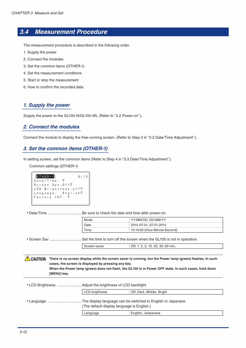
3. Set the common items (OTHER-1)
Insettingscreen,setthecommonitems(RefertoStep4in“3.3Date/TimeAdjustment”.).
Commonsettings(OTHER-1)
•Date/Time.................................Besuretocheckthedateandtimeafterpower-on.
Mode YY:MM:DD,DD:MM:YY
Date 2014-07-01,07-01-2014
Time 10:10:00(Hour:Minute:Second)
•ScreenSav...............................SetthetimetoturnoffthescreenwhentheGL100isnotinoperation.
Screen-saver Off,1,2,5,10,20,30,60min.
There is no screen display while the screen saver is running, but the Power lamp (green) flashes. In such
cases, the screen is displayed by pressing any key.
When the Power lamp (green) does not flash, the GL100 is in Power OFF state. In such cases, hold down
[MENU] key.
•LCDBrightness........................AdjustthebrightnessofLCDbacklight.
LCDbrightness Off,Dark,Middle,Bright
•Language.................................ThedisplaylanguagecanbeswitchedtoEnglishorJapanese.(ThedefaultdisplaylanguageisEnglish.)
Language English,Janpanese

3-13
CHAPTER3MeasureandSet
•FactoryINT..............................Returntothefactorysettings.
Allsettingswillbereset,sopleaseusecaution.
Yes:(ENTER) When[ENTER]keyispressed,thesettingsareinitialized.
No:(QUIT) Toquitthisscreenwithoutchanging,press[QUIT]key.
<Display language of GL100-N/GL100-WL>
InitialmenuisdisplayedinEnglish.
WhenyouwanttodisplayinEnglish,switchtoEnglishinaccordancewiththefollowingprocedure.
1) SupplythepowertotheGL100-N/GL100-WL.
2)Next,connectthemoduletotheGL100-N/GL100-WL(ExampleofGS-THconnection).
SENSOR ERROR!!
Please connect the sensor QUIT key to Power OffBAT LAN
Moduleunconnectedstate
”Please wait”
Recognitionofmoduletypes
GL100-**
Sleeping!! ENTER key to start
QUIT key to Power OffBAT LAN
Standbystate
Free-runningscreen
TEMP: +26.7HUM.: +39.8%
DEWP: +12.18BAT LAN SD S: 1.0s
STOP ALM. 1:28QUIT
STATUS
POWER
ENTER
MENU
STARTSTOP
3)Press[MENU]keytodisplaythesettingscreen.
Firstpageofthesettingscreenisdisplayed.
[AMP] 1/9Mode REF.TEMP ↑REF.TEMP +0.00
QUIT
STATUS
POWER
ENTER
MENU
STARTSTOP

3-14
CHAPTER3MeasureandSet
4)Displaythelanguagedisplayitem.
Press[MENU]keyuntilthe“OTHER-1”isdisplayed.
[OTHER-1] 7/9Date/Time: Screen Sav:Off LCD Brightness:Off Language: English Factory INIT:
QUIT
STATUS
POWER
ENTER
MENU
STARTSTOP
5)Selectthelanguagedisplay.
Using[ ]key,highlightthe“Language”(English).
[OTHER-1] 7/9Date/Time: Screen Sav:Off LCD Brightness:Off Language: English Factory INIT:
QUIT
STATUS
POWER
ENTER
MENU
STARTSTOP
Press[ENTER]keytodisplaythe“Language”settingscreen.
QUIT
STATUS
POWER
ENTER
MENU
STARTSTOP
[OTHER-1] 7/9Date/Time: Screen Sav:Off LCD Brightness:Off Language: English Factory INIT:
Japanese English
Using[ ]and[ ]keys,selectthe“English”.
[OTHER-1] 7/9Date/Time: Screen Sav:Off LCD Brightness:Off Language: English Factory INIT:
Japanese English
QUIT
STATUS
POWER
ENTER
MENU
STARTSTOP
Pressthe[ENTER]keytoconfirmit.
QUIT
STATUS
POWER
ENTER
MENU
STARTSTOP
[OTHER-1] 7/9Date/Time: Screen Sav:Off LCD Brightness:Off Language: English Factory INIT:
TheEnglishdisplayprocedureiscomplete.

3-15
CHAPTER3MeasureandSet
4. Set the measurement conditions
InSettingscreen,setthemeasurementconditions.
Themeasurementconditionsvariesdependingonthemodule.RefertotheUSER’SMANUALforeachmodule.
Thefollowingshowsanexample.(ExampleofGS-4VTconnection)
AMP
Settheconditionsofinputsignaltobemeasured.
(Thedisplayedinformationvariesdependingonthemodule.)
ALL Thesettingsof1to4channelscanbesetatatime.
1to4Input SetOff,Voltage,Temperature.
Range Voltage:20,50,100,200,or500mV,1,2,5,10,20,50V;1-5VTemperature:TC-K(K-typethermocouple),TC-T(T-typethermocouple)
LOGIC
Settheconditions(inputorslop)ofLogic/Pulseinputsignal.
(Thedisplayedinformationvariesdependingonthemodule.)
InputMode Off,Logic,Pulse
LOGIC InputSlope Off,On
Pulse InputSlope Off
Counts ↑ H,↓ LInst. ↑ H,↓ L

3-16
CHAPTER 3 Measure and Set
DATA
Set the data recording conditions.
• Sampling ..............................Sets the timing of data capture.
Sampling 0.5, 1, 2, 5, 10, 20, 30 sec.1, 2, 5, 10, 20, 30, 60 min.
• Capture MODE .......................Sets the interval of data file.
Capture MODE Continuous The data from the start to the stop is recorded in a file. However, the file size is approx. 1.9GB per one file.
1Hour Data file is generated every hour after starting.
24Hour Data file is generated every 24 hours after starting.
DatarecordedintheinternalmemoryormicroSDareplacedintheLOGfolder.
NumberoffilesthatcanbeplacedintheLOGfolderismaximum600files.
WhentheCaptureModeissetto1Hour,itislimitedtomaximum600filesatabout25days.
Whenrecordingforalongperiodoftime,pleasesettheCaptureModetoContinuousor24Hour.
• When"Continuous"isselected,thedatafileisnotgeneratedifthepowersupplyisshutdown.Inthiscase,itis
recommendedthatyouapplytheUSBpowerorsettothe"24Hour"or"1Hour"periodicallygenerateddatafile.
• Whenthe"CaptureMode"issetto1Houror24Hour,afewpointsofdatapointsmaybemoveddependingon
thesamplingrate.Duplicationandomissionofthedatadoesnotoccur.
• Capture DIST .......................Select the internal memory (4.9M bytes) or micro SD card.
However, you cannot select the micro SD card when it has not been inserted.
Capture DIST Memory, SD card
Recommended SD card: TS4GUSDHC4 (Transcend)
DatarecordedintheinternalmemoryormicroSDareplacedintheLOGfolder.
IfthenumberoffilesplacedinaLOGfolderincreases,therecordstartprocessingwilltakemoretime.Itis
recommendedtoregularlydeleteunnecessarydata.
However,numberoffilesthatcanbeplacedintheLOGfolderismaximum600files.
WhenafolderiscontainedintheLOGfolder,thefolderiscountedasasinglefile.
In[DATA]menu,youcancheckthecurrentnumberoffiles.
*WhentheGS-3ATisinstalled,thenumberoffilesisnotdisplayed.
*Usingthefollowingmethod,youcandeletethefiles.
•UsingtheUSB(LAN),connectbetweentheGL100andPCanddeletetheunnecessaryfilesbyusingthe
functionofthededicatedsoftware(GL100-APS).
•InserttheSDcardintothePCanddeletetheunnecessaryfilesbyusingthestandardPCfunction.

3-17
CHAPTER 3 Measure and Set
When selecting the SD cardWhen the “Capture DEST” is switched from Memory to SD card, the following screen is displayed.Press [ENTER] key to copy the contents in the Memory to the SD card.
When the copy is complete, the free space is checked and then the space is displayed.When pressing [QUIT] key, the free space is checked and then the space is displayed without copying it.
When selecting the MemoryWhen switching from SD card to Memory, the following screen is displayed.When [ENTER] key is pressed, the memory is erased. (It takes about 3 minutes.)
When pressing [QUIT] key, the Memory is set.
• If the power is not supplied to the module during copying the data to the micro SD, the micro SD may be
damaged.
When copying the data to the micro SD, please use the USB power.
• When copying the data in the internal memory to the micro SD, the data is copied to the LOG
folder in the micro SD. Number of files that can be placed in the LOG folder is maximum 600 files.
If there are more data in a LOG folder in the micro SD, the copy operation is slower. Please delete any
unnecessary data before copying.
Tip of memory recording time
The memory recording time varies depending on the memory capacity.For the recording time, refer to the recording time in the following table.
Recording conditions• Recording destination: Internal memory (calculated by 4.9MB)• Sampling: 30 sec. or 1 min.* Max. recording time = (Max. capacity÷Record length) x Sampling interval
Setting items ModelRecord length (Byte)
Max. recording time (reference value): Approx. (day)
Sampling 30 sec. Sampling 1 min.Temperature / humidity setting GS-TH 14 127 254
3-axis acceleration / temperature measurement
GS-3AT 12 148 297
4ch voltage / temperature measurement
GS-4VT 22 81 162
4ch thermistor temperature measurement
GS-4TSR 38 46 93
Illuminance / ultraviolet measurement
GS-LXUV 16 111 223
AC current / power measurement GS-DPA-AC 20 89 178
CO2 measurement GS-CO2 6 297 594
Temperature / humidity + CO2 measurement
GS-TH+GS-CO2 16 111 223
Temperature / humidity + illuminance / ultraviolet measurement
GS-TH+GS-LXUV 18 68 137
CO2 + illuminance / ultraviolet measurement
GS-CO2+GS-LXUV 26 99 198

3-18
CHAPTER 3 Measure and Set
TRIGGER
Set the data recording start/stop conditions.
• TRIG Setting .........................Set the recording start/stop conditions.
TRIG Setting Off Pressing the [START/STOP] key on this module will start/stop recording.
Start The recording will start with the trigger source conditions after pressing the [START/STOP] key.The recording will stop after pressing the [START/STOP] key.
Stop The recording will start after pressing the [START/STOP] keyand will be stopped with the trigger source conditions.
• TRIG Source ..........................Set the trigger conditions.
TRIG Source Off
Alarm Operates when alarm occurs.
Date/Time Operates with the set date and time.
• Whenthetriggerconditionalreadyhasbeensetisdisabled,therecordingisstartedassoonasyou
startameasurement.
<Ex.>
TRIGSetting:Start
TRIGSource:Alarm
Alarm:Off
• Whenthe3-axisAcceleration/TemperatureSensor(GS-3AT)isinstalled,thefollowingtriggersettingcanbe
usedbythePre-trigger.
Start:Off,Level,Alarm
Stop:Off
For the conditions that cannotbe set currently, the condition itemsset laterwill be enabled.
<Ex.>
WhensettingtheStarttriggertoDateinthestatethatthePre-triggerissetto50%,thePre-triggerwillbeOff.
ALARM
Set the conditions which the alarm information is sent.
(The settings vary depending on the module).
Alarm Off
Level Determine the conditions with the numerical setting.

3-19
CHAPTER 3 Measure and Set
I/F
The GL100-WL only can be set.
* When using the GL100-N, this cannot be set.
• WLAN Mode ........................Set the identifier of the access point.
Off This is the setting when the wireless function is not used.
Access point Base unit (When the base unit receives the connection request from the computers on the communication network, it intermediates the communication to the network.)
Station Set the child unit.
• DHCP ................................... IP address is automatically allocated.Access point
Set to On when you want to automatically allocate the IP address to the wireless LAN child unit (PC, smartphone, or tablet, etc.) connected to the GL100. Conversely, set to Off when setting IP address to the child unit without allocating it.
Station
When the wireless LAN base unit to be connected has DHCP function, by enabling the function, IP address is automatically allocated to the base unit. When the DHCP function is disabled, IP address is required to manually allocate in the TCP/IP page.
DHCP Off, On
• TCP/IP .................................Set the communication protocol of IP Address, Subnet Mask, and Gateway. (The values are an example.)
IP address 192.168.***.***Subnet mask 255.255.255.000
Gateway 192.168.***.***
• SSID ....................................This is the identification ID of wireless LAN.
The wireless LAN child unit to be connected to the GL100 is required to set with respect to the connection to this SSID. When operating the child unit in the access point mode, it is possible to use it without modification.

3-20
CHAPTER3MeasureandSet
•Security.................................WirelessLANconnectionisencryptedforsecurity.
ThroughthesettingsotherthanOff,athirdpartywhodoesnotknowthekeyisnotabletoconnecttotheGL100-WL.UsuallyusetheWPAorWPA2.
*Inthecaseofthestation,enterthesecurityschemeandencryptionkey.
Auto WPA/WPA2isautomaticallyidentified.Thisisnotusedinaccesspointmode.
Off Encryptionisdisabled.
WEP Thisisasimpleencryptionmethod.Onlyhalf-widthalphanumericcharactersareavailable.Setinnumberofcharactersof13characters.
WPA ThisismorerobustencryptionschemethanWEP.Onlyhalf-widthalphanumericcharactersareavailable.Setinnumberofcharactersfrom8charactersto63characters.
WPA2
•Key....................................... IdentificationofthebaseunitwhenconnectingintowirelessLAN.
Key Setthekeyinaccordancewiththesecuritysettings.
Tip of wireless LAN settings
WirelessLANfunctionissupportedintheGL100-WLonly.
TheGL100-WLhastwomodesof“Accesspoint”and“Station”.
Thefunctions,connectablemodule,andoperatingenvironmentofthe“Accesspoint”and“Station”arenotsame.
Access point (operated as base unit)
When1:1wirelessLANconnection(betweentheGL100andPC/smartphone/tablet)isenabled,thefollowingmodules
andoperatingenvironmentarerequired.
•PCorSmartphonethatcanbeconnectedtothewirelessLANwiththededicatedsoftware.
PCisachildunit.
Smartphoneisachildunit.
GL100-WLisabaseunit.Wirelessconnection
Wirelessconnection
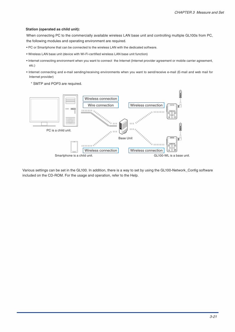
3-21
CHAPTER3MeasureandSet
Station (operated as child unit):
WhenconnectingPCtothecommerciallyavailablewirelessLANbaseunitandcontrollingmultipleGL100sfromPC,
thefollowingmodulesandoperatingenvironmentarerequired.
•PCorSmartphonethatcanbeconnectedtothewirelessLANwiththededicatedsoftware.
•WirelessLANbaseunit(devicewithWi-Fi-certifiedwirelessLANbaseunitfunction)
•InternetconnectingenvironmentwhenyouwanttoconnecttheInternet(Internetprovideragreementormobilecarrieragreement,
etc.)
•Internetconnectingande-mailsending/receivingenvironmentswhenyouwanttosend/receivee-mail(E-mailandwebmailfor
Internetprovider)
*SMTPandPOP3arerequired.
PCisachildunit.
Smartphoneisachildunit.
BaseUnit
GL100-WLisabaseunit.
Wireconnection Wirelessconnection
Wirelessconnection Wirelessconnection
Wirelessconnection
VarioussettingscanbesetintheGL100.Inaddition,thereisawaytosetbyusingtheGL100-Network_ConfigsoftwareincludedontheCD-ROM.Fortheusageandoperation,refertotheHelp.

3-22
CHAPTER3MeasureandSet
ThiscanbesetfortheGL100-WLonly.
*WhenusingtheGL100-N,thiscannotbeset.
[MAIL] 7/10Notification: User Info.: Server: AUTH/SSL: Destination: Reception:
•Notification............................Theinformationsentbye-mailcanbesettoOn/Off.
Alarmnotification Thealarminformationissentwhenthealarmoccurs.
BatteryLOW Thebatteryinformationissentwhenbatterylevelislow.
RadiofieldintensityLOW Theradioinformationissentwhenradiofieldintensityislow.
Diskfull ThememoryinformationissentwhenremainingcapacityofSDcardislow.
•UserInfo...............................Setthemailaddress,etc.ofGL100.
Mailaddress Setthee-maildestinationaddresswithin63characters.****@***.co.jp
Servername Settheuseraccountnamesofreceivingandsendingservers.Tosetindividually,usetheGL100-Network_Configsoftware.
Password Settheuserpasswordsofreceivingandsendingservers.Tosetindividually,usetheGL100-Network_Configsoftware.
•Server..................................SetthemailsendingserveroftheGL100.
POPServer Setthemailreceivingserver.
POPPort SettheportnumberinaccordancewiththePOPSofAUTH/SSL.OFF:110STARTTLS:143OVERSSL:993Fordetailedsettings,followthePOPserveravailable.
SMTPServer Setthemailsendingserver.
SMTPPort SettheportnumberinaccordancewiththeAUTH/SSL.OFF:25STARTTLS:587OVERSSL:465Fordetailedsettings,followtheSMTPserveravailable.
•AUTH/SSL............................Setthee-mailauthenticationandencryption.
AUTH(SMTP) Off,POP,SMTP-AUTH
SMTP-AUTH PLAIN,CRAM-MDS
POPS Off,STARTTLS,OVERSSL
SMTPS Off,STARTTLS,OVERSSL

3-23
CHAPTER3MeasureandSet
•Destination.............................Setthemaildestinationandsubject.
TO ****@***.co.jpSetwithin63characters.
CC aaaaa@***.co.jpSetwithin63characters.
CC bbbbb@***.co.jpSetwithin63characters.
CC ccccc@***.co.jpSetwithin63characters.
CC ddddd@***.co.jpSetwithin63characters.
Subject Setthesubjectwithin63characters.
•Reception...............................Setthemailreceivingtimeintervalandmaildataprocessing.
Receivinginterval Setthereceivingintervalto1to1440min.
Sendingtest Thetestresultsaredisplayedafterperformingthesendingtest.
Receivingtest Thetestresultsaredisplayedafterperformingthereceivingtest.
OTHER-1
Thedisplayedinformationvariesdependingonthemodule.
•Date/Time..................................Alwayscheckitafterpower-on.
Mode YY:MM:DD,DD:MM:YY
Date 2014-07-01,07-01-2014
Time 10:10:00(Hour:Minute:Second)
•ScreenSav..................................SetthetimetoturnoffthescreenwhentheGL100isnotinoperation.
ScreenSaver Off,2,5,0,20,30,60min.
There is no screen display while the screen saver is running, but the Power lamp (green) flashes. In such
cases, the screen is displayed by pressing any key.
When the Power lamp (green) does not flash, the GL100 is in Power OFF state. In such cases, hold down
[MENU] key.
•LCDBrightness...........................AdjustthebrightnessofLCDbacklight.
LCDbrightness Off,Dark,Middle,Bright
•Language....................................ThedisplaylanguagecanbeswitchedtoEnglishorJapanese.(ThedefaultdisplaylanguageisEnglish.)
Language EnglishorJapanese
•FactoryINT................................Returntothefactorysettings.
Allsettingswillbereset,sopleaseusecaution.
Yes:(ENTER) When[ENTER]keyispressed,thesettingsareinitialized.
No:(QUIT) Toquitthisscreenwithoutchanging,press[QUIT]key.

3-24
CHAPTER3MeasureandSet
OTHER-2
Thedisplayedinformationvariesdependingonthemodule.
•TEMP.Unit.........................SetforGS-4VT,GS-3AT,andGS-TH.
TEMP.Unit SwitchthetemperatureunittoCelsius(°C)orFahrenheit(°F).
•RoomTEMP.........................SetforGS-4VT.
RoomTEMP. Switchtoroomtemperaturecompensationorexternalcompensation
•BurnOut..............................SetforGS-4VT.
BurnOut Setthesensordisconnectiondisplayforthethermocouple.Whenthesensorisnotconnectedordisconnected,theconnectionstateisdisplayedinthescreen.
•ACC.Unit..............................SetforGS-3AT.
ACC.Unit SwitchtheaccelerationunittoGorm/s2.
•CO2Calibration....................SetforGS-CO2.
CO2Calibration Calibratetheminimumvaluewithinacertainperiodoftimewithrespecttothereferencevalue.ThisisusefulintheenvironmentCO2concentrationislow.
Whenthesettingsarecomplete,press[QUIT]keytodisplaythefree-runningscreen.

3-25
CHAPTER3MeasureandSet
5. Start or stop the measurement
Measurement start operation
Preparationof1to4sectionsiscomplete,pressthe[START/STOP]key.
+34.1 L:OFF+0.0001V L:OFF+0.0500V L:OFF +0.05V L:OFFBAT LAN SD S: 1.0s
ARMED ALM. 1:28QUIT
STATUS
POWER
ENTER
MENU
STARTSTOP
The“ARMED”isdisplayeduntilthetriggerconditionissatisfiedfrom“STOP”.
Whenthetriggerconditionissatisfied,the“REC”isdisplayed.
Operationdisplayduringmeasurement
Themodule’sstatusisshownwiththelampdisplay.
QUIT
STATUS
POWER
ENTER
MENU
STARTSTOP
AccessingSDcard Accesslight
Lowbattery Flashonceevery5seconds
Alarmactive Flashonceevery10seconds
STATUS(Orange)
Powersupplying Flashonceevery10seconds
WirelessLANconnectionpossiblestatus
Flashonceevery10seconds
POWER(Green)
• When accessing an SD card, do not remove the SD card. The data may not write properly or the SD card
may be damaged.
• When “ low battery” is displayed, replace the battery or connect the USB interface to supply power as
soon as possible. Caution: Batteries cannot be replaced when recording data. Replace them after the
recording has finished.

3-26
CHAPTER3MeasureandSet
Measurement stop operation
Tostoprecording,pressthe[START/STOP]key.
QUIT
STATUS
POWER
ENTER
MENU
STARTSTOP
GL100-**
Sleeping!! ENTER key to start
QUIT key to Power OffBAT LAN
Since the measured data is recorded in file until the “ Sleeping!!” screen is displayed by pressing the [STOP]
key, it takes some time before the screen is switched. Press [ENTER] key to return to the free-running
screen.
Press[ENTER]keytoreturntothefree-runningscreen.
QUIT
STATUS
POWER
ENTER
MENU
STARTSTOP

3-27
CHAPTER3MeasureandSet
6. How to confirm the recorded data
Whenyouwanttoconfirmtherecordeddata,replaythedataonPCorSmartphonewiththededicatedsoftware.
(1) OnlinedataconfirmationusingUSBI/F
ConnectbetweenthePCandGL100-N/GL100-WLusingUSBcable.
USBCable
Therecordeddatacanbeconfirmedbystarting theapplicationsoftwareandselecting thememory(internal
memoryorSDcard).
(2) DirectdataconfirmationbyinsertingSDcard
Therecordeddatacanbeconfirmedby insertingtherecordedSDcard into theSDcardslotonthePCand
selectingtheSDcardusingtheapplicationsoftware.
microSD
microSD
(1)
(2)
microSDcard
SDcardslot
ToremovethemicroSDcard,pushthecardgently.

3-28
CHAPTER 3 Measure and Set
(3) Data confirmation on PC through wireless LAN connection
In the case of wireless LAN connection, this function is disabled unless the communicating conditions are
established.
The “I/F” and ”MAIL” in “3.4 Measurement Procedure” are required to set. Connect between the GL100 and PC
and then set them using the attached GL100-Network_Config software.
• Direct setting of the GL100
[MAIL] 7/10Notification: User Info.: Server: AUTH/SSL: Destination: Reception:
[I/F Setting] [MAIL Setting]
• Wireless LAN and Mail settings using the GL100-Network Config.
Using the “GL100-Network_Config” software included on the attached CD-ROM, perform various settings with
reference to Help.
Date/Time adjustment, wireless LAN setting, and mail send/receive setting, etc. can be performed.
(4) Smart device application software
Using the smart device application software (iOS/Android), the data during recording can be checked and
controlled.
The software is available from AppStore (iOS) or GooglePlay (Android).
Digital display, waveform display (Available only when replaying.)
4-1
CHAPTER4Specification
CHAPTER 4 SpecificationThischapterdescribesthebasicspecificationsfortheGL100.
Product Summary
4.1 Standard Specifications4.2 Standard Specifications (Module)4.3 Specifications of Application Software

4-2
CHAPTER 4 Specification
4.1 StandardSpecifications
GL100-N/GL100-WL
Item ContentsInput channel number This depends on the type of module to be used.Input terminal shapeInput methodExternal input/output Alarm output 1 channelPC I/F USB (Micro-B connector)
Wireless LAN (GL100-WL only)* ON/OFF can be set (It is set to ON at the factory.)
Built-in memory device Main Memory: approximate 4.9M ByteExternal memory: microSD card (Please use a commercially available product)* 1 file cannot exceed 1.9GB.* A microSD card which supports sleep mode is recommended TS4GUSDHC4 (Transcend) etc.
Backup function Setup conditions: EEPROMClock: Backup capacitorTime need for backup during battery exchange: approx. 10 hours (at 23°C)
Monitor Graphic monochrome display (128×64 dot)Display contents Measured values, settings, etc.
Note: Recorded data cannot be viewed on this module. Please use the included application software.
Wireless LAN(GL100-WL only)
Standards: IEEE 802.11bCommunication distance: approx. 40 m* It depends on the surrounding obstacles and environmental conditionsReal-time data transfer rate: 500 ms maximum
Functions USB I/F Real-time display, measured data readout, module settings (PCapplication)Wireless LAN Real-time display, measurement data readout, module settings
(Android / iOS smartphone application), Email reception functionNote: GL100-WL only
Alarm output type Insulation switching type by photo couplerRating: 30V, 50 mA (power dissipation 150 mW)
Memory content Recorded DataSimple waterproof body IP54 *1
Vibration proof Automobile parts Type 1 Class A equivalenRated power GL100-N: Max. 3.0VA, GL100-WL: Max. 3.5VA
* It depends on the type of module to be used.Power supply AA alkaline batteries 2 pcs., USB Bus power (5V 200mA or more)
* USB cable for Micro B-A is included.Batteries and USB AC adapter (5V 1A or more) are not included.
Usage environment -10 to 50°C, 80% RH or less (non-condensing)External dimensions[W×D×H] (approximate)
66 × 100 × 27 mm (not including protruding parts)
Weight (approximate) GL100-N : 125 g, GL100-WL : 130 g
*1: The IP54 can only be used when the GL100 and module are connected, and the connector over and battery cover are closed. We recommend replacing the packing periodically.

4-3
CHAPTER4Specification
External View
Unit:mm
Dimensionalaccuracy:±2mm

4-4
CHAPTER4Specification
4.2 Standard Specifications (Module)
4ch Voltage / Temperature Terminal (GS-4VT): Optional
Item ContentsMeasurementdata Voltage/Temperature/Logic,Pulsecount(Instant,Accumulation)Measurementchannels Voltage/Temperature4channels
Logic/Pulsecount4channelsInputmethod ScansystembyPhoto-MOSrelay,All-channelisolatedinputMeasurementvoltagerange 20,50,100,200,500mV
1,2,5,10,20,50V1-5VF.S.Measuredvoltageaccuracy 0.15%ofF.S.Inputresistance 1MΩ±5%Temperaturecoefficie Gain:±0.01%ofF.S./°C
Zero:±0.02%ofF.S./°CAllowablesignalsourceresistance
300Ωorless
Maximuminputvoltage Inputterminal+/-interval:60Vp-pInputterminal/Inputterminalinterval:60Vp-pInputterminal/GNDinterval:60Vp-p
Withstandvoltage Inputterminal/Inputterminalinterval:350Vp-p1min.Inputterminal/GNDinterval:350Vp-p1min.
Insulationresistance Inputterminal/GNDinterval:50MΩormore(atDC500V)Commonmoderejectionratio 90dBormore(50/60Hzsignalsource300Ωorless)Noise 48dbormore(+/-atshort)Measurementtemperaturerange
<Thermocouple> K-200to1370°C T-200to400°C
Measuredtemperatureaccuracy
<K-typethermocouple>-200≤TS≤-100±(0.05%ofrdg+2.0°C)-100<TS≤1370°C±(0.05%ofrdg+1.0°C)<T-typethermocouple>-200≤TS≤-100±(0.1%ofrdg+1.5°C)-100<TS≤400°C±(0.1%ofrdg+0.5°C)Referencejunctioncompensationaccuracy:±0.5ºC
Logic/PulseInput Inputvoltagerange:0to+24V(Onelinegroundinput)Inputsignal:No-voltagecontact(acontact,bcontact,NO,NC)Opencollector,voltageinputInputthresholdvoltage:approx.+2.5VHysteresis:approx.0.5V(+2to-2.5V)
Pulsemeasurementrange
Instant:max.200C/SamplingAccumulation:max.65535C
Roomtemperaturecompensation ON/OFFTemperatureuni Selectfrom°C(Celsius)/°F(Fahrenheit)Samplinginterval 0.5,1,2,5,10,20,30sec.
1,2,5,10,20,30,60min.Alarm OFF/LevelCableLength Approximate20cmUsageenvironment -10to50°C,80%RHorless(non-condensing)Externaldimensions[W×D×H](approximate)
46×66×35.5mm(notincludingprotrudingparts)
Weight(approximate) 85g

4-5
CHAPTER4Specification
External View
Unit:mm
Dimensionalaccuracy:±2mm

4-6
CHAPTER4Specification
3-axis Acceleration / Temperature Sensor (GS-3AT): Optional
Item ContentsMeasurementdata Acceleration(3-axis)/TemperatureAccelerationrange ±2G(20m/s
2),±5G(50m/s2),±10G(100m/s2)
Measuredaccelerationaccuracy(Non-linearity)
±2%ofF.S.
Band 0to100HzNoise 25mGrmsMeasurementtemperaturerange
-10to50°C(14°Fto122°F)
Measuredtemperatureaccuracy
-10≤TS≤50±1.0(°C)
Responsetime(temperature)
Approx.300sec.
Measurementmode MemorymodeandDirectmodeMemorycapacity(Memorymode)
16,32,64,128ksample
Pre-trigger(Memorymode)
OFF/10,25,50,100%
Samplinginterval <Memorymode>5,10,20,50,100ms<Directmode>0.5,1,2,5,10,20,30sec.1,2,5,10,20,30,60min.
Alarm OFF/LevelADJUSTfunction Set/Reset
Note:Thisfunctionwillsetthecurrentstaticaccelerationvaluetozero.Waterproofsensor IP54Cablelength Approximate20cmUsageenvironment -10to50°C,80%RHorless(non-condensing)Externaldimensions[W×D×H](approximate)
51×36×19.5mm(notincludingprotrudingparts)
Weight(approximate) 64g

4-7
CHAPTER4Specification
External View
Unit:mm
Dimensionalaccuracy:±2mm

4-8
CHAPTER4Specification
4ch Thermistor Terminal (GS-4TSR): Optional
Item ContentsMeasurementdata Temperature/Logic,Pulsecount(Instant,Accumulation)Measurementchannels Temperature4channels
Logic/Pulsecount4channelsInputmethod Scanmethod,non-isolatedinput(Thermistorinput)Temperaturerange TypeA:-40°Cto105°C(GS-103AT-4P)
TypeJ:-40°Cto120°C(GS-103JT-4P)Measuredtemperatureaccuracy
<Mainmodule> -40≤TS<0±0.7(°C) 0≤TS≤35±0.2(°C) 35<TS≤70±0.4(°C) 70<TS≤120±1.0(°C)<Thermistorsensor> ±0.4°C(Typicalvalue)
Logic/PulseInput Inputvoltagerange:0to+24V(Onelinegroundinput)Inputsignal: No-voltagecontact(acontact,bcontact,NO,NC), Opencollector,voltageinputThresholdlevel:approx.+2.5VHysteresis:approx.0.5V(+2to+2.5V)
Pulsemeasurementrange Instant:Max.200C/SamplingAccumulation:Max.65535C
Temperatureunit Selectfrom°C(Celsius)/°F(Fahrenheit)Samplinginterval 0.5,1,2,5,10,20,30sec.
1,2,5,10,20,30,60min.Triggers Starttrigger:OFF,LEVEL,ALARAM,DATE
Stoptrigger:OFF,LEVEL,ALARAMAlarm OFF/LevelCablelength Approximate20cmUsageenvironment -10to50°C,80%RHoreless(non-condensing)Externaldimensions[W×D×H](approximate)
46×66×35.5mm(notincludingprotrudingparts)
Weight(approximate) 83g

4-9
CHAPTER4Specification
External View
Unit:mm
Dimensionalaccuracy:±2mm

4-10
CHAPTER4Specification
Adapter for AC Current Sensor (GS-DPA-AC): Optional
Item ContentsMeasurementdata Current,power,accumulatedpower
*Theaccumulatedpowerisdisplayedonlywhenrecording.Connectablesensors 50AACCurrentSensor(GS-AC50A)
100AACCurrentSensor(GS-AC100A)200AACCurrentSensor(GS-AC200A)*Thisisoptional.
Measurementchannel Connectablesensor:upto2channelsMeasuredcurrentaccuracy
<Module+Sensor>±2.0%FS±1digitAmbienttemperature23°C,Ratedinput,Ratedfrequency
Frequencytobemeasured 50Hz/60HzApplicablecircuit Single-phase2-wire
Single-phase3-wire3-phase3-wire
Measuredvaluedisplayfunction
Currentandpower(Instantaneouspoweroraccumulatedpowerconsumption)
Primaryratedcurrent 50AACCurrentSensor:50A100AACCurrentSensor:100A200AACCurrentSensor:200A
Withstandvoltage Betweencaseandallinput/outputterminalsintervalAC1000V,50/60Hz,1min.
Samplinginterval 0.5,1,2,5,10,20,30sec.1,2,5,10,20,30,60min.
Alarm OFF/LevelCablelength Approx.20cmUsageenvironment -10to50°C,80%RHorless(non-condensing)Externaldimensions[W×D×H](approximate)
46×66×27.4mm(notincludingprotrudingparts)
Weight(approximate) 55g
AC Current Sensor Specifications
TheACCurrentSensorhasthespecificationsbelow.Becarefulwhenhandlingit.
Item ContentsMax.allowablecurrent GS-AC50A:100Arms
GS-AC100A:200ArmsGS-AC200A:300Arms
Withstandvoltage AC2200V,1min.(betweenexternalcaseandoutputterminals)Insulationresistance DC500V,100MΩormore(betweenexternalcaseandoutputterminals)Windowdiameter GS-AC50A:φ10mm
GS-AC100A:φ16mmGS-AC200A:φ24mm
Operatingtemperatureandhumidity
-10to50°C,80%RHorless(non-condensing)
Cablelength Approx.20cmExternaldimensions[W×D×H](approximate)
GS-AC50A:26.4x25.5x43.3mmGS-AC100A:27.4x30.5x46.2mmGS-AC200A:48.4x35x40mm
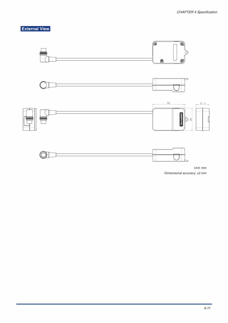
4-11
CHAPTER4Specification
External View
Unit:mm
Dimensionalaccuracy:±2mm

4-12
CHAPTER 4 Specification
Illumination / Ultraviolet Sensor (GS-LXUV): Optional
Item ContentsMeasurement data Illuminance, ultraviolet, accumulated illuminance, accumulated ultraviolet intensity
* The accumulated illuminance and ultraviolet intensity are displayed only when recording.Measurement channel Illuminance: 1 channel
UV intensity: 1 channelMeasurement range Illuminance: 0 to 200k lx
UV intensity: 0 to 30 mW / cm2
Measurement accuracy *1 Illuminance: ±5% (at 25°C)Ultraviolet intensity: ±5% (at 25°C)
Spectral sensitivity Illuminance: 400 to 750 nm (peak 560 nm)UV intensity: 260 to 400 nm (peak 370 nm)
Measurement resolution Illuminance: 0.1 lxUV intensity: 0.001 mW/cm2
Responsive Illuminance: 1 ms or lessUV intensity: 1 ms or less
Accumulated function Accumulated illuminance: 0 to 999,999 k lxhAccumulated UV intensity: 0 to 999,999 mW/cm2h
Sampling interval 0.5, 1, 2, 5, 10, 20, 30 sec.1, 2, 5, 10, 20, 30, 60 min.
Alarm OFF / LevelCable length Approximate 20 cmUsage environment -10 to 50°C, 80% RH or less (non-condensing)External dimensions[W×D×H] (approximate)
46 × 66 × 19 mm (not including protruding parts)
Weight (approximate) 65 g
*1: This is the measurement accuracy when our standard light source is used and compared with the calibrated test instrument.

4-13
CHAPTER4Specification
External View
Unit:mm
Dimensionalaccuracy:±2mm

4-14
CHAPTER4Specification
CO2 Sensor (GS-CO2): Optional
Item ContentsSensormethod NDIRsystemMeasurementdata CO2densityMeasurementchannel 1channelMeasurementdensityrange
0to9999ppm
Measurementdensityaccuracy
±(5%ofrdg+30ppm)*Withintherangeof0to5000ppm
Responsive 3minutesorlessSamplinginterval 0.5,1,2,5,10,20,30sec.
1,2,5,10,20,30,60min.*Theprocessingofsensorisevery2sec.Evenifsettingitto0.5or1sec.,thedataisprocessedatthesamevalue(2sec.).
Alarm OFF/LevelCablelength Approximate20cmUsageenvironment 0to50°C,80%RHorless(non-condensing)Externaldimensions[W×D×H](approximate)
66×100×24.6mm(notincludingprotrudingparts)
Weight(approximate) 99g
*Werecommendreplacingthemoduleperiodically.

4-15
CHAPTER4Specification
External View
Unit:mm
Dimensionalaccuracy:±2mm

4-16
CHAPTER4Specification
Temperature / Humidity Sensor (GS-TH): Optional
Item ContentsMeasurementdata Temperature,humidity,dewpointtemperature(calculatedvalue),accumulatedtemperature
*Theaccumulatedtemperatureisdisplayedonlywhenrecording.Measurementsystem C-MOSSensorMeasurementtemperaturerange -20°Cto85°CMeasuredtemperatureaccuracy
-20≤TS<0±0.8(°C)0≤TS≤60±0.5(°C)60<TS≤85±0.8(°C)
Measurementhumidityrange 0.0to100.0%RHMeasuredhumidityaccuracy 25°C
0≤RH<10±10(%)10≤RH<20±8(%)20≤RH≤80±5(%)80<RH≤90±8(%)90<RH≤100±10(%)
Responsetime Temperatureandhumidity:100sec.(63%response,25°CAirflowrate1m/s)*Thesensor’sresponsivenessisaffectedbythemeasuredtemperatureandairflowrate.
Samplinginterval 0.5,1,2,5,10,20,30sec.1,2,5,10,20,30,60min.
Alarm OFF/LevelWaterprooftreatment SensorunitWithwaterprooffilterTemperatureunit Selectfrom°C(Celsius)/°F(Fahrenheit)Usageenvironment Withinthemeasurementrangeoftemperatureandhumidity
However,setittotheenvironmentiftheGl100andthissensorareinthesameenvironment.Externaldimensions[W×D×H](approximate)
15×45×10.2mm(notincludingprotrudingparts)
Weight(approximate) 14g
*Werecommendreplacingthemoduleperiodically.

4-17
CHAPTER4Specification
External View
Unit:mm
Dimensionalaccuracy:±2mm

4-18
CHAPTER4Specification
GS Branch Adapter(GS-DPA): Optional
Item ContentsNumberofconnectors 2channelsConnectablesensor Temperatureandhumiditysensor(GS-TH)
Illumination/ultravioletsensor(GS-LXUV)CO2sensor(GS-CO2)
Cablelength Approximate20cmUsageenvironment -10to50°C,80%RHorless(non-condensing)Externaldimensions[W×D×H](approximate)
46×66×27.4mm(notincludingprotrudingparts)
Weight(approximate) 68g

4-19
CHAPTER4Specification
External View
Unit:mm
Dimensionalaccuracy:±2mm

4-20
CHAPTER4Specification
4.3 Specifications of Application Software
GL100-APS
Item ContentsSupportedOS Windows8.1/8/7/Vista(64/32bit)Connectioninterface USB,WirelessLANFunction Modulecontrol,real-timedatarecording,fileconversion,datareplayModuleSetting Input,recording,alarm,andtriggersettingsRecordeddata Real-timedata(GBDbinary,CSV)
MemorydataSDcarddata
Displayedinformation Analogwaveform,logicwaveform,pulsewaveform,digitalvalueDisplaymode Y-Tdisplay,digitaldisplay,statisticsandhistorydisplays,cursordisplaybetweentheXandY
(replayonly)Fileconvert Betweencursors,alldata,cullingfunctionMonitorfunction SendinganE-mailtotheaddressspecifiedinthealarmmonitoring,periodicallysendingE-mailReportfunction Dailyreportandmonthlyreportfilesareautomaticallygenerated.
GL100-Network_Config
Item ContentsSupportedOS Windows8.1/8/7/Vista(64/32bit)Connectioninterface USBFunction USBdriverinstallation,GL100firmwareupdate,timeadjustment,modulenamesetting,
wirelessLANsettings,E-mailsendandreceivesettings
Smart Device Application Software
Item ContentsSupportedOS iOS(7.0orhigher),Android(4.1orhigher)Connectioninterface WirelessLANFunction Digitaldisplay,waveformdisplay(onlywhenreplaying),recordingstart/stopcontrol,
samplingintervalchange,E-mailsendingmodulecontrolfunction,customizedfunction

I-1
INDEX
INDEX
MMAIL . . . . . . . . . . . . . . . . . . . . . . . . . . . . . . . . . . . . . . . ..3-22Measurement.Procedure .. .. .. .. .. .. .. .. .. .. .. .. .. .. .. .. .. .. .. .. .. .. .. ..3-12microSD. . . . . . . . . . . . . . . . . . . . . . . . . . . . . . . . . . . . . . ..2-7microSD.slot. . . . . . . . . . . . . . . . . . . . . . . . . . . . . . . . . . ..2-4Module.Connection.Terminal . . . . . . . . . . . . . . . . . . . . . ..2-4Module.connection.terminal. . . . . . . . . . . . . . . . . . . . . . ..2-6Module. . . . . . . . . . . . . . . . . . . . . . . . . . . . . . . . . . . . . . . ..2-3Monitor . . . . . . . . . . . . . . . . . . . . . . . . . . . . . . . . . . . . . . ..2-4Mounting.screw.holes. . . . . . . . . . . . . . . . . . . . . . . . . . . ..2-4
NNomenclature.and.Functions . . . . . . . . . . . . . . . . . . . . . ..2-4
OOperating.Environment. . . . . . . . . . . . . . . . . . . . . . . . . . ..1-3Operation.key. . . . . . . . . . . . . . . . . . . . . . . . . . . . . . . . . ..2-4OTHER-1. . . . . . . . . . . . . . . . . . . . . . . . . . . . . . . . . . . . ..3-23OTHER-2. . . . . . . . . . . . . . . . . . . . . . . . . . . . . . . . . . . . ..3-24
PPower-on. . . . . . . . . . . . . . . . . . . . . . . . . . . . . . . . . . . . . ..3-3
SSafety.Precautions. . . . . . . . . . . . . . . . . . . . . . . . . . . . . . . ..iiSpecifications.of.Application.Software. . . . . . . . . . . . . ..4-20Standard.Accessories. . . . . . . . . . . . . . . . . . . . . . . . . . . ..2-2Standard.Specifications . . . . . . . . . . . . . . . . . . . . . . . . . ..4-2Standard.Specifications.(Module). . . . . . . . . . . . . . . . . . ..4-4
TTemperature./.Humidity.Sensor . . . . . . . . . . . . . . . . . . ..2-25time.adjustment. . . . . . . . . . . . . . . . . . . . . . . . . . . . . . . . ..3-8To.Ensure.Safe.and.Correct.Use . . . . . . . . . . . . . . . . . . . . ..iTRIGGER . . . . . . . . . . . . . . . . . . . . . . . . . . . . . . . . . . . ..3-18
UUSB.I/F. . . . . . . . . . . . . . . . . . . . . . . . . . . . . . . . . . . . . . ..2-7USB.I/F.terminal. . . . . . . . . . . . . . . . . . . . . . . . . . . . . . . ..2-4
VVarious.Connections. . . . . . . . . . . . . . . . . . . . . . . . . . . . ..2-6
WWarming-up. . . . . . . . . . . . . . . . . . . . . . . . . . . . . . . . . . . ..1-4
Sign3-axis.Acceleration./.Temperature.Sensor. . . . . . . . . . ...2-114ch.Thermistor.Terminal. . . . . . . . . . . . . . . . . . . . . . . . ...2-134ch.Voltage./.Temperature.Terminal. . . . . . . . . . . . . . . . ..2-8
AAccessories. . . . . . . . . . . . . . . . . . . . . . . . . . . . . . . . . . . ..2-3Adapter.for.AC.Current.Sensor. . . . . . . . . . . . . . . . . . . ...2-16Adapter.for.Branch.Adapter . . . . . . . . . . . . . . . . . . . . . ..2-27ALARM. . . . . . . . . . . . . . . . . . . . . . . . . . . . . . . . . . . . . ..3-18Alarm.Output.Terminal . . . . . . . . . . . . . . . . . . . . . . . ..2-4,.2-7AMP. . . . . . . . . . . . . . . . . . . . . . . . . . . . . . . . . . . . . . . . ..3-15
BBattery.cover. . . . . . . . . . . . . . . . . . . . . . . . . . . . . . . . . . ..2-4Before.Setting.Up. . . . . . . . . . . . . . . . . . . . . . . . . . . . . . ..3-2
CChecking.the.Accessories . . . . . . . . . . . . . . . . . . . . . . . ..2-2CO2.Sensor. . . . . . . . . . . . . . . . . . . . . . . . . . . . . . . . . . ..2-24Connector.cover. . . . . . . . . . . . . . . . . . . . . . . . . . . . . . . ..2-4
DDATA. . . . . . . . . . . . . . . . . . . . . . . . . . . . . . . . . . . . . . . ..3-16date.adjustment. . . . . . . . . . . . . . . . . . . . . . . . . . . . . . . . ..3-8
EExternal.View . . . . . . . . . . . . . . . . . . . . . . . . . . . . . . . . . ..4-3
HHook.bracket. . . . . . . . . . . . . . . . . . . . . . . . . . . . . . . . . . ..2-4How.to.confirm.the.recorded.data. . . . . . . . . . . . . . . . . ..3-27How.to.connect.AC.adapter . . . . . . . . . . . . . . . . . . . . . . ..3-6How.to.connect.to.PC. . . . . . . . . . . . . . . . . . . . . . . . . . . ..3-6How.to.install.the.batteries. . . . . . . . . . . . . . . . . . . . . . . ..3-5How.to.Switch.On.the.Power . . . . . . . . . . . . . . . . . . . . . ..3-3How.to.Switch.to.Power.OFF.Mode . . . . . . . . . . . . . . . . ..3-4
II/F . . . . . . . . . . . . . . . . . . . . . . . . . . . . . . . . . . . . . . . . . ..3-19Illumination./.Ultraviolet.Sensor . . . . . . . . . . . . . . . . . . ..2-22
LLOGIC. . . . . . . . . . . . . . . . . . . . . . . . . . . . . . . . . . . . . . ..3-15


Specificationsaresubjecttochangewithoutnotice.
GL100SeriesUser'sManualGL100-UM-151
September120141stedition-01
GRAPHTEC CORPORATION


