
IOM100GVAE0809Software Version 2.0
Automation Solutions for oil & gas, defense and aviation applications
Installation and Operations M
anual D
ispatch and Fuels Accounting 8232 Data Capture Unit (with Bluetooth Wireless)Electronic data acquisition and wireless communication system for use with aircraft fueling equipment

Data Capture Unit
Varec, Inc. i
CopyrightAll rights reserved. Printed in the United States of America. Except as permitted under the United States Copyright Act of 1976, no part of this publication may be reproduced, stored in a retrieval system or transmitted in any form or by any means—electronic, mechanical, photocopying, recording or otherwise - without the prior written permission of the Publisher:
Varec, Inc.5834 Peachtree Corners EastNorcross (Atlanta) GA 30092USA
Trademarks AcknowledgedVarec, Inc. recognizes all other trademarks. Trademarks of other products mentioned in this document are held by the companies producing them.
FuelsManager®, TankView®, TacFuels®, Varec®, and FuelsManager IntoPlane® are registered trademarks of Varec, Inc.
Modbus® is a registered trademark of the Modbus Organization, Inc.
Veeder-Root® EMR3 ™ is a registered trademark of the Veeder-Root Company
Liquid Controls® LectroCount™ LCR-II® is a registered trademark of Liquid Controls, a Unit of the IDEX Corporation
Bluetooth® is a registered trademark of the Bluetooth Special Interest Group
All other product and service names mentioned are the trademarks of their respective companies.
Product Approvals (Pending)This document and the information provided within are controlled by the approvals agency(s) listed below. All changes to this document must be submitted to and approved by the agency(s) before public release.
• FM Approvals (FM) • Canadian Standards Association (CSA)

ii Installation and Operations Manual
Disclaimer of WarrantiesThe contract between the Seller and the Buyer states the entire obligation of the Seller. The contents of this instruction manual shall not become part of or modify any prior or existing agreement, commitment, or relationship between the Seller and Buyer. There are no express or implied warranties set out in this instruction manual. The only warranties that apply are those in the existing contract between the Seller and Buyer.
The 8232 Data Capture Unit (DCU) has not been tested by Varec under all possible operational conditions, and Varec may not have all the data relative to your application. The information in this instruction manual is not all inclusive and does not and cannot take into account all unique situations. Consequently, the user should review this product literature in view of his or her application. If you have any further questions, please contact Varec for assistance.
Limitations of Seller's LiabilityIn the event that a court holds that this instruction manual created some new warranties, Seller's liability shall be limited to repair or replacement under the standard warranty clause. In no case shall the Seller's liability exceed that stated as Limitations of Remedy in the contract between the Seller and Buyer.
Use of parts that are not manufactured or supplied by Varec voids any warranty and relieves Varec of any obligation to service the product under warranty. Varec recommends the use of only Varec manufactured or supplied parts to maintain or service Varec 8232 Data Capture Units.
Terms of UseThe information provided in this document is provided “as is” without warranty of any kind. Varec, Inc. disclaim all warranties, either express or implied, including the warranties of merchantability and fitness for a particular purpose. In no event shall Varec, Inc. or its suppliers be liable for any damages whatsoever including direct, indirect, incidental, consequential, loss of business profits or special damages, even if Varec, Inc. or its suppliers have been advised of the possibility of such damages.
This manual is solely intended to describe product installation and functions and should not be used for any other purpose. It is subject to change without prior notice. This manual was prepared with the highest degree of care. However, should you find any errors or have any questions, contact one of our service offices or your local sales agent.

Data Capture Unit
Varec, Inc. iii
Safety PrecautionsRead this manual carefully and make sure its contents are understood before using this product. Follow all instructions and safety guidelines presented in this manual when using this product. If the user does not follow these instructions properly, Varec cannot guarantee the safety of the system.
Note Comply with all applicable regulations, codes, and standards. For safety precautions, the user should refer to the appropriate industry or military standards.
Caution Electrical Hazard! Read and understand static and lightning electrical protection and grounding described in API 2003. Make certain that the 8232 Data Capture Unit instal-lation, operation, and maintenance conforms with the practice set forth therein.

iv Installation and Operations Manual

Data Capture Unit
Varec, Inc. v
Contents
1 Introduction . . . . . . . . . . . . . . . . . . . . . . . . . . . . . . . . . . . . . . . . . . . . . . . . . . . . . 1
Overview . . . . . . . . . . . . . . . . . . . . . . . . . . . . . . . . . . . . . . . . . . . . . . . . . . . . . . . . . . 1
Features . . . . . . . . . . . . . . . . . . . . . . . . . . . . . . . . . . . . . . . . . . . . . . . . . . . . . . . . . . 1
Hardware Description . . . . . . . . . . . . . . . . . . . . . . . . . . . . . . . . . . . . . . . . . . . . . . . . 2
8232 Data Capture Unit . . . . . . . . . . . . . . . . . . . . . . . . . . . . . . . . . . . . . . . . . . . 2Wireless Interface Module . . . . . . . . . . . . . . . . . . . . . . . . . . . . . . . . . . . . . . . . . 4
Software Description. . . . . . . . . . . . . . . . . . . . . . . . . . . . . . . . . . . . . . . . . . . . . . . . . 5Bluetooth Communications . . . . . . . . . . . . . . . . . . . . . . . . . . . . . . . . . . . . . . . . . 5The 8232 DCU Application software . . . . . . . . . . . . . . . . . . . . . . . . . . . . . . . . . . 5Pulse Data Collection . . . . . . . . . . . . . . . . . . . . . . . . . . . . . . . . . . . . . . . . . . . . . 5Volumetric Fuel Data Communication . . . . . . . . . . . . . . . . . . . . . . . . . . . . . . . . . 54-20 mA Analog Input Channel . . . . . . . . . . . . . . . . . . . . . . . . . . . . . . . . . . . . . . 5Resistive Temperature Detector (RTD) . . . . . . . . . . . . . . . . . . . . . . . . . . . . . . . . 5
2 Installation . . . . . . . . . . . . . . . . . . . . . . . . . . . . . . . . . . . . . . . . . . . . . . . . . . . . . . 7
Safety Guidelines . . . . . . . . . . . . . . . . . . . . . . . . . . . . . . . . . . . . . . . . . . . . . . . . . . . 7
General Safety Guidelines . . . . . . . . . . . . . . . . . . . . . . . . . . . . . . . . . . . . . . . . . 7Installation Safety Guidelines . . . . . . . . . . . . . . . . . . . . . . . . . . . . . . . . . . . . . . . 8
Mounting the 8232 DCU to the Fueling Vehicle . . . . . . . . . . . . . . . . . . . . . . . . . . . . 8
Wiring the 8232 DCU . . . . . . . . . . . . . . . . . . . . . . . . . . . . . . . . . . . . . . . . . . . . . . . 10Wiring Diagram – with Electronic Meter Register (LCR-II). . . . . . . . . . . . . . . . . . . 10Wiring Diagram – with Electronic Meter Register (EMR3) . . . . . . . . . . . . . . . . . . . 10Wiring Diagrams – with External Pulse Transmitter . . . . . . . . . . . . . . . . . . . . . . . 11
Optional Wiring Diagrams . . . . . . . . . . . . . . . . . . . . . . . . . . . . . . . . . . . . . . . . . . . . 12
Wiring Diagram – Front 8232 Terminals . . . . . . . . . . . . . . . . . . . . . . . . . . . . . . . 12Wiring Diagram – with a 4-20 Self-Powered Transmitter. . . . . . . . . . . . . . . . . . . . 13Wiring Diagram – with the RTD Transmitter . . . . . . . . . . . . . . . . . . . . . . . . . . . . 13Wiring Diagram – with the Output Transmitter . . . . . . . . . . . . . . . . . . . . . . . . . . . 14Wiring Diagram – with High Drivers . . . . . . . . . . . . . . . . . . . . . . . . . . . . . . . . . . 14Wiring Diagram – with the 4-20 mA Loop-Powered Transmitter . . . . . . . . . . . . . . 15Wiring Diagram – with a Multiplexed Dual 4-20 mA Loop Powered Transmitter. . . . 15
Terminal Assignments . . . . . . . . . . . . . . . . . . . . . . . . . . . . . . . . . . . . . . . . . . . . . . 16
Setting DIP Switches . . . . . . . . . . . . . . . . . . . . . . . . . . . . . . . . . . . . . . . . . . . . . . . 18Locating and Using DIP Switches . . . . . . . . . . . . . . . . . . . . . . . . . . . . . . . . . . . 18DIP Switch Settings . . . . . . . . . . . . . . . . . . . . . . . . . . . . . . . . . . . . . . . . . . . . . 18
3 Configuration . . . . . . . . . . . . . . . . . . . . . . . . . . . . . . . . . . . . . . . . . . . . . . . . . . 21
Setting the Meter Factor for the Fueling Meter (Register) . . . . . . . . . . . . . . . . . . . 21
Setting the Battery Voltage and Current Limits. . . . . . . . . . . . . . . . . . . . . . . . . . . . 22
Setting up the EMR3 Electronic Meter . . . . . . . . . . . . . . . . . . . . . . . . . . . . . . . . . . . 22

Contents
vi Installation and Operations Manual
Setting up the LCR-II Electronic Meter . . . . . . . . . . . . . . . . . . . . . . . . . . . . . . . . . . 22
Determining the RS-232 Protocol . . . . . . . . . . . . . . . . . . . . . . . . . . . . . . . . . . . . . . 23
Assigning the EMR3 Point Status Bits. . . . . . . . . . . . . . . . . . . . . . . . . . . . . . . . . . . 23
Assigning the LCR-II Point Status Bits . . . . . . . . . . . . . . . . . . . . . . . . . . . . . . . . . . 24
4 Maintenance and Troubleshooting . . . . . . . . . . . . . . . . . . . . . . . . . . . . . 25
Maintenance . . . . . . . . . . . . . . . . . . . . . . . . . . . . . . . . . . . . . . . . . . . . . . . . . . . . . . 25
Troubleshooting . . . . . . . . . . . . . . . . . . . . . . . . . . . . . . . . . . . . . . . . . . . . . . . . . . . 27Using Local Diagnostics (LED Indicators) . . . . . . . . . . . . . . . . . . . . . . . . . . . . . . 27Returning the 8232 DCU to Factory Default Settings . . . . . . . . . . . . . . . . . . . . . . 28Resetting the 8232 DCU. . . . . . . . . . . . . . . . . . . . . . . . . . . . . . . . . . . . . . . . . . 28Replacing a Fuse. . . . . . . . . . . . . . . . . . . . . . . . . . . . . . . . . . . . . . . . . . . . . . . 28
5 Specifications. . . . . . . . . . . . . . . . . . . . . . . . . . . . . . . . . . . . . . . . . . . . . . . . . . 29
Primary Components . . . . . . . . . . . . . . . . . . . . . . . . . . . . . . . . . . . . . . . . . . . . . . . 29
Safety Approvals (Pending) . . . . . . . . . . . . . . . . . . . . . . . . . . . . . . . . . . . . . . . . . . 29
Electrical . . . . . . . . . . . . . . . . . . . . . . . . . . . . . . . . . . . . . . . . . . . . . . . . . . . . . . . . . 29
Switches, Indicators, and Connectors. . . . . . . . . . . . . . . . . . . . . . . . . . . . . . . . . . . 29
Pulse Input . . . . . . . . . . . . . . . . . . . . . . . . . . . . . . . . . . . . . . . . . . . . . . . . . . . . . . . 30
6 Ordering Information . . . . . . . . . . . . . . . . . . . . . . . . . . . . . . . . . . . . . . . . . . . 31
Order Codes . . . . . . . . . . . . . . . . . . . . . . . . . . . . . . . . . . . . . . . . . . . . . . . . . . . . . . 31

Varec, Inc. 1
1 Introduction
This manual is designed to assist the user with the installation, configuration, operation, maintenance, and troubleshooting of the Varec 8232 Data Capture Unit (DCU).
Overview
The 8232 DCU is an electronic fueling data acquisition and wireless communications device for use on aircraft fueling equipment. The 8232 DCU sends metered volume data upon request to a handheld PC via Bluetooth wireless technology. It can be used with 3rd–party pulse transmitters, Liquid Controls® LectroCount™ LCR-II®, or Veeder-Root® EMR3™ electronic meter registers.
Figure 1-1: 8232 DCU - Cover Removed
Features
• Real-time, embedded, multi-tasking operating system• Communicates directly with Fuels Manager Aviation IntoPlane clients
via industry-standard Bluetooth technology• Includes 2 pulse count channels for connecting up to 2 pulse transmitters• Includes 1 serial channel for digital communications• Works with 3rd-party pulse transmitters• Works with the Liquid Controls® LectroCount™ LCR-II® Electronic Meter Register
• Works with the Veeder-Root® EMR3 Electronic Meter Register• NEMA 4 enclosure• Optimized for low-power and battery power operation• Power output terminals for powering up to two external pulse transmitters or other external
devices• Configurable for constant or on-demand power output to pulse transmitter(s) or other
external devices• Output power options are dip switch configurable (depends on software version)• LED status indicators• Watchdog Monitoring circuit• Includes a 3-Wire Platinum or Copper Resistive Temperature Device (RTD) Interface

Introduction
2 Installation and Operations Manual
• Includes a 4-20 mA Analog Input Channel• Includes 1 Solid State Relay Output Channel• Includes 2 High Side Output Drivers
Hardware Description
The 8232 DCU consists of the following hardware components:
A. Cover B. Model 8232 Bluetooth and I/O Interface BoardC. 8230 Microprocessor BoardD. Sealed antenna feed-through E. 2.4 GHz external antennaF. NEMA 4 - rated enclosure
Figure 1-2: 8232 DCU Components
8232 Data Capture Unit
The 8232 Data Capture Unit processor board is the core component of the 8232 DCU. This board conditions, acquires and totalizes pulse input signals, performs low and high level communications processing, and executes the Bluetooth protocols as well as application software. The processor also performs hardware and power monitoring.
Pulse Totalization
The primary data acquisition function of the 8232 DCU is totalization of 2 pulse input channels from external pulse transmitter(s). Pulse data is combined with a meter factor to calculate the volume of fuel pumped.
DF
A
B
C
E

Data Capture Unit
Varec, Inc. 3
Pulse Blanking
The 8232 DCU uses a pulse blanking circuit to determine the stability of signals received from the pulse transmitter(s). Only signals that are stable for the duration of a blanking pulse are used.
The blanking pulse duration can be configured for each channel independently from 500 µs to 6000 ms in 65535 linear steps. This feature is used for additional input frequency band filtering and is especially useful for de-bouncing mechanical switches and contacts.
Low Power and Battery Power
The 8232 DCU is optimized for low power and battery power operation. The input voltage is 6 VDC or 12 VDC. The application software allows the processor to be placed in a low power static mode for extended periods of time in order to minimize power consumption in battery powered applications. Power is connected to the 8232 DCU by a 2 position, pluggable terminal block. The power terminals are protected from a reverse polarity connection, surge, and over-voltage conditions. The positive terminal is fused to limit an over-current condition.
Output Power
The 8232 DCU provides one power output terminal (J3) for powering external devices, as shown in Figure 1-3. The 8232 DCU can power up to two external pulse transmitters.
Input Voltage and Current Monitoring
The 8232 DCU incorporates both input voltage and current monitoring circuits. The FuelsManager IntoPlane system can collect voltage and current values to generate exception reports for users. The 8232 DCU also has an on board temperature sensor circuit for monitoring the operating temperature of the unit.
DIP Switches
The 8232 DCU contains 8 DIP switches. These switches are used to enable LEDs, diagnostics, and control other settings as described in detail in section Setting DIP Switches on page 18.
Introduction
4 Installation and Operations Manual
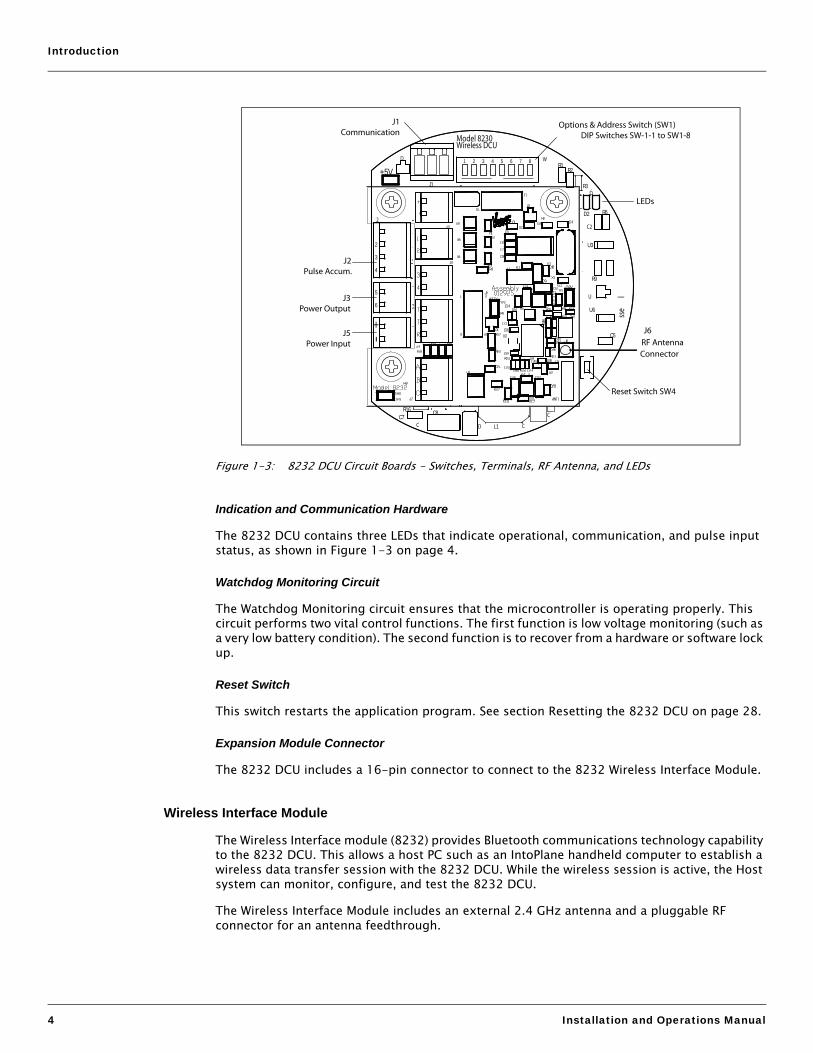
Figure 1-3: 8232 DCU Circuit Boards - Switches, Terminals, RF Antenna, and LEDs
Indication and Communication Hardware
The 8232 DCU contains three LEDs that indicate operational, communication, and pulse input status, as shown in Figure 1-3 on page 4.
Watchdog Monitoring Circuit
The Watchdog Monitoring circuit ensures that the microcontroller is operating properly. This circuit performs two vital control functions. The first function is low voltage monitoring (such as a very low battery condition). The second function is to recover from a hardware or software lock up.
Reset Switch
This switch restarts the application program. See section Resetting the 8232 DCU on page 28.
Expansion Module Connector
The 8232 DCU includes a 16-pin connector to connect to the 8232 Wireless Interface Module.
Wireless Interface Module
The Wireless Interface module (8232) provides Bluetooth communications technology capability to the 8232 DCU. This allows a host PC such as an IntoPlane handheld computer to establish a wireless data transfer session with the 8232 DCU. While the wireless session is active, the Host system can monitor, configure, and test the 8232 DCU.
The Wireless Interface Module includes an external 2.4 GHz antenna and a pluggable RF connector for an antenna feedthrough.
R16
5
J1
1 2 3 4 5 6 7 8
3
4
+5V
L1
D2
R2
6
R6
C7
R1
+
-
U6
R3
R9
C5
C8
2 U3
Wireless DCU
W
sse
l
D
D
C
CC
Model 8230
C2
U
2
D
J6
RF AntennaConnector
J1Communication
J5Power Input
J3Power Output
J2Pulse Accum.
LEDs
Reset Switch SW4
Options & Address Switch (SW1) DIP Switches SW-1-1 to SW1-8

Data Capture Unit
Varec, Inc. 5
Software Description
Bluetooth Communications
The 8232 DCU does not initiate any wireless connection sessions. Communication sessions are initiated by a remote device such as an IntoPlane handheld PC. The Bluetooth transceiver provides automatic scanning of input channels and provides remote control of output channels. The RTD and the 4-20 mA input scanning can be enabled and disabled remotely through the host interface to the wireless DCU. The host can access additional data items through the Modbus register map.
The 8232 DCU Application software
The primary functions of the 8232 DCU software are to collect and process pulse data (when used with pulse transmitters), collect digital volume and temperature and flow data (when used with electronic meter registers), and to communicate to a host device.
Pulse Data Collection
When used with 3rd–party pulse transmitters, the 8232 DCU uses pulse data and a scale factor stored in the 8232 DCU database to calculate the volume of fuel pumped. Once volumetric data is calculated, this data is written to the real-time database.
Volumetric Fuel Data Communication
The 8232 DCU can send volumetric fuel data using the Bluetooth wireless virtual serial channel or using a hardwired EIA232-C serial port. The 8232 DCU also supports two high-level communication protocols: the industry-standard MODBUS protocol, and a proprietary Varec protocol, compatible with the ViewRTU diagnostic and configuration tool. The 8232 DCU automatically switches to the appropriate protocol.
4-20 mA Analog Input Channel
The 4-20mA analog input channel is used to scan two multiplexed transmitters. Both transmitters are connected as loop-powered devices. The loop positive signals from the transmitters are connected to the two high side output driver channels. These output drivers provide the loop power to the transmitters. The loop negative signals from the transmitters are connected to the input of the 4-20 mA channel. If enabled, the wireless 8232 DCU turns on the high side drivers individually to power a single transmitter. After allowing the transmitter to stabilize, the wireless 8232 DCU records an analog measurement. The wireless 8232 DCU will continue to cycle through enabling and measuring the signal of the two transmitters. The wireless 8232 DCU firmware calculates an average signal value for each transmitter. Although this is a very low band width measurement technique, it is sufficient for measuring the average values of some analog signals.
If the wireless DCU is interfacing with a single 4-20 mA transmitter, the firmware can be enabled to perform continuous scanning of the single transmitter for a higher band width measurement.
Resistive Temperature Detector (RTD)
The Resistive Temperature Detector interface is used to measure temperature. The interface supports 3-wire copper and platinum RTD(s).

Introduction
6 Installation and Operations Manual

Varec, Inc. 7
2 Installation
Installing the 8232 DCU hardware on a fueling vehicle consists of the following procedures:
1. Mounting the 8232 DCU to the fueling vehicle (see Section Mounting the 8232 DCU to the Fueling Vehicle on page 8)
2. Wiring the 8232 DCU (see Section Wiring the 8232 DCU on page 10)
3. Setting DIP switches (see Section Setting DIP Switches on page 18)
Note After installing the 8232 DCU hardware, proceed to Chapter 3, Configuration.
! Warning Before attempting installation of the 8232 DCU on fueling equipment, review the Safety Guidelines below. Installation and maintenance personnel should become familiar with any hazards present as well as any agency requirements before working with any equipment.
Safety Guidelines
General Safety Guidelines
The 8232 DCU is certified to be used in Class I, Division 2, Groups A - D hazardous locations. (Pending)
The user should follow safety guidelines provided by the Occupational Safety and Health Administration (OSHA) for additional protection. Information may be obtained from the following sources:
• National Electrical Code (NEC)• National Fire Protection Association (NFPA)• Instrument Society of America (ISA)• FM Approvals (FM)• Underwriters’ Laboratories Incorporated (UL)• Canadian Standards Association (CSA)
When in doubt about the safety of an area, the user should check with the local safety authorities. Always observe warning signs posted in the area and all labels on equipment.

Installation
8 Installation and Operations Manual
Installation Safety Guidelines
• Never attempt to make voltage measurements within the 8232 DCU in the field.• Maintenance should be performed only by authorized personnel.• Always turn off the power before removing the case cover.• Before installing/repairing any wiring to the 8232 DCU, make sure that the power is turned
off at the main circuit breaker or switch. The power switch should be locked in the OFF position and labeled to prevent other personnel from turning the power on during installation.
• Before turning on power when installation is complete, make sure the cover of the 8232 DCU case is in place and tightly closed. NEVER REMOVE ANY COVERS WITHOUT FIRST TURNING OFF THE POWER.
• To prevent shock hazards, the housing of all units should be properly grounded in accordance with the National Electrical Code. A grounding conductor should be wired to the grounding terminal provided on the 8232 DCU.
• Caution should be exercised when entering any area that is posted or otherwise assumed to contain hazardous gases. Always follow the guidelines provided by the Occupational Safety and Health Administration for your own protection.
• Never perform maintenance with power applied.
Mounting the 8232 DCU to the Fueling Vehicle
Prepare a mounting platform on the fueling vehicle, with close proximity to a battery power source and the pulse transmitter. For platform and drill hole dimensions, refer to Figure 2-1.

Data Capture Unit
Varec, Inc. 9
Figure 2-1: 8232 DCU Dimensions
4.75
Antenna rotates
90 deg.
3.94
6.1255.50
.890
.890
.890.890
5.23
2.81
3.78
3.19
4.69
3.875
Top View
Side View
“
“
“
“
““
“
“
“
““
“
“
“

Installation
10 Installation and Operations Manual
Wiring the 8232 DCU
The 8232 DCU can be used with Liquid Controls’ LCR-II, Veeder-Root’s EMR3 electronic meter registers, or with one or two external pulse transmitters. This section provides wiring diagrams and terminal assignments for all options.
Wiring Diagram – with Electronic Meter Register (LCR-II)
Figure 2-2: 8232 DCU Wiring Diagram - with LCR-II Electronic Meter Register
Wiring Diagram – with Electronic Meter Register (EMR3)
Figure 2-3: 8232 DCU Wiring Diagram - with EMR3Electronic Meter Register
+
-
G
R
T
GNDCTSRXDTXDRTS+12
LCR J3
Battery
DIP Switches
1234
56
+
Meter 2 +Meter 2 -Meter 1 +Meter 1 -
Output Power +Output Power -
Input Power +- Input Power -
J1
Reset Switch SW4
GND
RXDTXD
EMR3RS-232
Serial Port
+
-
G
R
T
Battery
DIP Switches
1234
56
+
Meter 2 +Meter 2 -Meter 1 +Meter 1 -
Output Power +Output Power -
Input Power +- Input Power -
J1
Reset Switch SW4

Data Capture Unit
Varec, Inc. 11
Wiring Diagrams – with External Pulse Transmitter
There are three options for connecting the 8232 DCU to external pulse transmitter(s):
• Constant battery power to the pulse transmitter, as shown in Figure 2-4.• On-Demand Power to Pulse Transmitter, as shown in Figure 2-5.• Connection to Dry Contact Pulse Transmitter, as shown in Figure 2-6.
Figure 2-4: 8232 DCU Wiring Diagram - Constant Battery Power to Pulse Transmitter
Figure 2-5: 8232 DCU Wiring Diagram - On-Demand Power to Pulse Transmitter
+
-
Green Wire - Ground
Black Wire - One Channel OutputWhite Wire - Common
Red Wire +10 to 15 VDC
Battery
PulseTransmitter
EnclosureGroundTerminal
DIP Switches
1234
56
+
Meter 2 +Meter 2 -Meter 1 +Meter 1 -
Output Power +Output Power -
Input Power +- Input Power -
J1
Reset Switch SW4
Enclosure GroundTerminal
Green Wire - Ground
Black Wire - One Channel Output
Red Wire - +10 to 15 VDC
White Wire - Common
+
-
Battery
PulseTransmitter
DIP Switches
1234
56
+
Meter 2 +Meter 2 -Meter 1 +Meter 1 -
Output Power +Output Power -
Input Power +- Input Power -
J1
Reset Switch SW4

Installation
12 Installation and Operations Manual
Figure 2-6: 8232 DCU Wiring Diagram - Connection to Dry Contact Pulse Transmitter
Optional Wiring Diagrams
Wiring Diagram – Front 8232 Terminals
Figure 2-7: Front 8232 Terminals
Green Wire - Ground
Black Wire (Contact Terminal 1)
Black Wire (Contact Terminal 2)
+
-
WireJumper
Enclosure GroundTerminal
PulseTransmitter
Battery
DIP Switches
1234
56
+
Meter 2 +Meter 2 -Meter 1 +Meter 1 -
Output Power +Output Power -
Input Power +- Input Power -
J1
Reset Switch SW4
+
-
12
3
4
T
T
R
ABC
4-20 mA Transmitter Input
4-20 mA Transmitter Return
Input DC PowerTypically 24VInput DC PowerTypically 24V
+
-
RTD SignalRTD Return 1RTD Return 2
4-20 mA Transmitter Input
High Side Output Driver 1High Side Output Driver 2
Solid State Relay Terminal 1
Solid State Relay Terminal 2
Model 8232

Data Capture Unit
Varec, Inc. 13
Wiring Diagram – with a 4-20 Self-Powered Transmitter
Figure 2-8: 4-20 mA Self-Powered Transmitter
Wiring Diagram – with the RTD Transmitter
Figure 2-9: RTD Model
Multiplexed4-20 mASelf-Powered Transmitter
+
-
+
-
12
34
TTR
ABC
4-20 mA Transmitter Input4-20 mA Transmitter Return
Input DC PowerTypically 24VInput DC PowerTypically 24V
+
-
RTD SignalRTD Return 1RTD Return 2
4-20 mA Transmitter Input
High Side Output Driver 1High Side Output Driver 2
Solid State Relay Terminal 1Solid State Relay Terminal 2
Model 8232
RTD
+
-
12
34
TTR
ABC
4-20 mA Transmitter Input4-20 mA Transmitter Return
Input DC PowerTypically 24VInput DC PowerTypically 24V
+
-
RTD SignalRTD Return 1RTD Return 2
4-20 mA Transmitter Input
High Side Output Driver 1High Side Output Driver 2
Solid State Relay Terminal 1Solid State Relay Terminal 2
Model 8232

Installation
14 Installation and Operations Manual
Wiring Diagram – with the Output Transmitter
Figure 2-10: Output Transmitter
Wiring Diagram – with High Drivers
Figure 2-11: High Drivers
+ 24 V
LOAD
0 V
+
-
12
34
TTR
ABC
4-20 mA Transmitter Input4-20 mA Transmitter Return
Input DC PowerTypically 24VInput DC PowerTypically 24V
+
-
RTD SignalRTD Return 1RTD Return 2
4-20 mA Transmitter Input
High Side Output Driver 1High Side Output Driver 2
Solid State Relay Terminal 1Solid State Relay Terminal 2
Model 8232
+ 24 V
0 V
LOAD LOAD
+
-
12
34
TTR
ABC
4-20 mA Transmitter Input4-20 mA Transmitter Return
Input DC PowerTypically 24VInput DC PowerTypically 24V
+
-
RTD SignalRTD Return 1RTD Return 2
4-20 mA Transmitter Input
High Side Output Driver 1High Side Output Driver 2
Solid State Relay Terminal 1Solid State Relay Terminal 2
Model 8232

Data Capture Unit
Varec, Inc. 15
Wiring Diagram – with the 4-20 mA Loop-Powered Transmitter
Figure 2-12: 4-20 mA Loop-Powered Transmitter
Wiring Diagram – with a Multiplexed Dual 4-20 mA Loop Powered Transmitter
Figure 2-13: Multiplexed Dual 4-20 mA Loop-Powered Transmitter
24 V Power
4-20 mALoop-Powered Transmitter
-
+
+
-
+
-
12
34
TTR
ABC
4-20 mA Transmitter Input4-20 mA Transmitter Return
Input DC PowerTypically 24VInput DC PowerTypically 24V
+
-
RTD SignalRTD Return 1RTD Return 2
4-20 mA Transmitter Input
High Side Output Driver 1High Side Output Driver 2
Solid State Relay Terminal 1Solid State Relay Terminal 2
Model 8232
24 V Power
MultiplexedDual 4-20 mALoop-Powered Transmitters
-+
+
-
+
-
+
-
12
34
TTR
ABC
4-20 mA Transmitter Input4-20 mA Transmitter Return
Input DC PowerTypically 24VInput DC PowerTypically 24V
+
-
RTD SignalRTD Return 1RTD Return 2
4-20 mA Transmitter Input
High Side Output Driver 1High Side Output Driver 2
Solid State Relay Terminal 1Solid State Relay Terminal 2
Model 8232

Installation
16 Installation and Operations Manual
Terminal Assignments
To locate the terminal connectors on the 8232 DCU circuit boards, refer to the preceding wiring diagrams or to Figure 1-3 on page 4.
Note DIP switch SW1-1 must be closed to enable the EIA232-C hardware.
Connector Terminal Indicator/No
Signal Name Description
J1Communication
T TXD EIA232-C Transmit Data (Normally Connected to Receive Data of Host Device)
R RXD EIA232-C Receive Data (Normally Connected to Transmit Data of Host Device)
G GND EIA232-C Ground
J2Pulse Accumulator
1 2+ Pulse Channel 2 + Signal (5-30 V)
2 2- Pulse Channel 2 - Signal
3 1+ Pulse Channel 1 + Signal (5-30 V)
4 1- Pulse Channel 1 - Signal
J3Power Output
5 Out+ + Power Output (for powering pulse transmitter)
6 Out- - Power Output
J5Power Input
+ + + Power Supply Input (8-30 VDC)
_ _ - Power Supply Input

Data Capture Unit
Varec, Inc. 17
To locate the terminal name/number on the 8232 DCU circuit boards, refer to the preceding wiring diagrams or to Figure 1-3 on page 4.
Terminal Name/Number Terminal Description Description
+ Positive Input DC Power — Typically 24V This terminal provides input power for the two high side output drivers. This terminal has a diode for reverse polarity protection. Fuse F1 provides fusing capability for the input power.
- Negative Input DC Power — Typically 24V When using 4-20mA loop powered transmitters, this terminal provides the negative return path for DC power.
1 High Side Output Driver 1 This terminal provides positive output for driving a load or a 4 mA transmitter. This output is automatically driven by software when enabling the Analog Input function to control multiplexed transmitter control. When used as a digital output, this driver is mapped to Digital Output 2 (DO2).
2 High Side Output Driver 2 This terminal provides positive output for driving a load or a 4 mA transmitter. This output is automatically driven by software when enabling the Analog Input function to control multiplexed transmitter control. When used as a digital output, this driver is mapped to Digital Output 3 (DO3).
3 Solid State Relay Terminal 1 This terminal provides connection 1 to the 1 Form-A solid state relay. The relay is mapped to Digital Output 1 (DO1).
4 Solid State Relay Terminal 2 This terminal provides connection 2 to the 1 Form-A solid state relay. The relay is mapped to Digital Output 1 (DO1).
T 4-20 mA Transmitter Input This terminal provides positive connection point for Analog signals from 4-20 mA transmitters. Two T terminals are provided for ease in connecting two multiplexed 4-20 mA self-powered transmitters.
R 4-20 mA Transmitter Return This terminal provides a negative return reference when using a 4-20 mA self-powered transmitter.
A RTD Signal This terminal provides a connection for a 3-wire RTD signal.
B RTD Return 1 This terminal provides a connection for a 3-wire RTD return 1.
C RTD Return 2 This terminal provides a connection for a 3-wire RTD return 2.

Installation
18 Installation and Operations Manual
Setting DIP Switches
Locating and Using DIP Switches
To locate the DIP switches on the 8232 DCU circuit board, see Figure 1-3 on page 4. Figure 2-14 shows how to close (turn on) or open (turn off) a DIP switch.
Figure 2-14: 8232 DCU DIP Switch Operation
DIP Switch Settings
8232 DCU Addressing
The default DCU address is DCU XXX, with XXX = the last three hexadecimal digits of the Bluetooth Device Address. This is a unique 40–bit number (10 hexadecimal digits) that is programmed into the Bluetooth transceiver module in the 8232 DCU.
1 2 3 4 5 6 7 8
-------------- OPEN -------------- Press this side of switch to open(turn off)
Press this side of switch to close(turn on)

Data Capture Unit
Varec, Inc. 19
DIP Switch Settings
Note The 8232 DCU switch settings are read during startup. After changing the position of any switch(es), the 8232 DCU must be reset before the new settings take effect.
SW1-3 and SW1-7 determine the RS-232 port protocol. To set the protocol consult the table below. Also note that SW-1 must be closed to enable the RS-232 port.
Note Only set SW1-6 in the open position if the LCR-II is programmed with firmware version SR215.
Note If both SW1-3 and SW1-7 are closed, J1 Port protocol will default to the diagnostic protocol (RTU Slave).
Switch Function Function: Open(after reset)
Function: Close(after reset)
SW1-1 Control of diagnostic hardware – LEDs and J1 RS-232 circuit
LEDs and RS-232 circuits are disabled.
LEDs and RS-232 circuits are enabled.
SW1-2 Hard Reset Control
After Reset – Configuration data is preserved (see Section Returning the 8232 DCU to Factory Default Settings on page 28 for details).
After Reset – All configuration data is set to default values.
SW1-3 Liquid Control Protocol *
J1 RS-232 Port uses diagnostic protocol (RTU Slave).
J1 RS-232 Port uses Liquid Control Protocol for interface with LCR-II.
SW1-4 Output Port J3 Configuration
Output Port J3 drives at Vin voltage when active.
Output Port J3 drives at 5 VDC when active.
SW1-5 Output Port J3 Control
Output Port J3 is continually active. Output Port J3 is disable when the IntoPlane computer is disconnected.
SW1-6 LCR-II Controls Option
Commands are not issued to control the LCR-II (LCR-II operates independent of WDCU).
Older interface method in which the WDCU controls the operation of the LCR-II.
SW1-7 Veeder Root Protocol *
J1 RS-232 Port uses diagnostic protocol (RTU Slave).
J1 RS-232 Port uses Veeder Root Protocol for interface with EMR3.
SW1-8 EMR3 Dual Meter Control
EMR3 is configured for a single meter register.
EMR3 is configured for dual meter registers.

Installation
20 Installation and Operations Manual

Varec, Inc. 21
3 Configuration
Configuring the 8232 DCU consists of the following procedures:
• Setting the meter factor for the fueling register (for use with pulse transmitters only)• Setting battery voltage and current limits
• Setting up the EMR3 Electronic Meter Register• Setting up the LCR-II Electronic Meter Register• Determining the RS-232 protocol
• Assigning the EMR3 point status bits• Assigning the LCR-II point status bits
Setting the Meter Factor for the Fueling Meter (Register)
A pulse transmitter sends a specific number of pulses per volume of fuel pumped. This number varies with the manufacturer and model of transmitter used.
To account for this variation, the 8232 DCU uses a meter factor to arrive at an accurate number of pulses per rotation (volume pumped). For example, a pulse transmitter that transmits 10 pulses per gallon of fuel would require a meter factor of 10.
To set the meter factor using an IntoPlane handheld device:
1. Log on.
2. Select the Other button.
3. Select DCU Config. The Available DCUs screen appears and the handheld unit searches for available DCUs.
4. Select the appropriate DCU, and then select OK.
5. On the DCU Configuration screen, select the Meters button.
6. From the Name drop-down list, select Meter 1 or Meter 2.
7. Enter the equipment ID tag in the DCU Tag field. This is the ID selected in step 4.
Note When using the 8232 DCU with the LCR-II Electronic Meter Interface, the Acc. Value, Rollover, and Pulse Ratio are read from the LCR-II Electronic Meter Interface. These values cannot be modified using the handheld.
Note When using the 8232 DCU with the EMR3 Electronic Meter Interface, the Meter Roll-over, Pulse Ratio, and Meter Value are read from the EMR3 Electronic Meter Interface and cannot be changed via the DCU configuration screen. Only the Meter Name and DCU Tag values are modifiable when using the EMR3.
8. In the Acc. Value field, enter the current accumulator value from the register.
9. In the Rollover field, enter the reliever value for the register. For example, for a seven-digit register, this value would be 9999999.
10. In the Pulse Ratio field, enter the pulse ratio for the pulse transmitter.
11. Select Save.

Configuration
22 Installation and Operations Manual
Setting the Battery Voltage and Current Limits
Use this procedure to set the Lower Voltage Limit and the Upper Current Limit for monitoring the battery power supplied to the 8232 DCU. This configuration is for the FuelsManager Aviation Handheld.
To set the battery limits for an 8232 DCU:
1. Log on.
2. Select the Other button.
3. Select DCU Config. The Available DCUs screen appears and the handheld unit searches for available DCUs.
4. Select the appropriate DCU, and then select OK.
5. On the DCU Configuration screen, select the Battery button. The Set Battery Limits screen appears.
6. Enter a number in the Lower Voltage Limit (V) field.
7. Enter a number in the Upper Current Limit (mA) field.
8. Select Save.
Setting up the EMR3 Electronic Meter
1. The EMR3 must be configured for 9600 Baud, 8 Data Bits, 1 Stop Bit, and No Parity.
2. The EMR3 must be configured with an IB address of 1.
3. If using a single register, the EMR3 display Head Address must be configured as 1.
4. If using dual registers, the EMR3 display Head Addresses must be configured as 1 and 2.
5. Port 2 must be setup as “OBC”.
6. The Display Syntax for the Totalizer Volume must be set to 88888888.
Setting up the LCR-II Electronic Meter
1. The LCR must be configured for 19200 Baud, 8 Data Bits, and No Parity.
2. The LCR must be configured with an address of 1.
3. J10 must be set to 485 or the “P” position.
4. Firmware version SR215 for independent operation.

Automatic Tank Gauge
Varec, Inc. 23
Determining the RS-232 Protocol
SW1-3 and SW1-7 determine the RS-232 port protocol. To set the protocol, examine Table 3-1 below.
Note When in EMR_Master mode, the DCU constantly polls the EMR3 Meter. The only data retrieved is the Gross Totalizer Volume.
Assigning the EMR3 Point Status Bits
The following table lists the EMR3 point status bits and a description of each. Refer to the Veeder-Root Manuals for other EMR3 settings.
SW1-3 SW1-7 Protocol
OPEN OPEN RTU Slave
OPEN CLOSED EMR Master
CLOSED OPEN LCR Master
CLOSED CLOSED RTU Slave
Table 3-1: 8232 DCU Configuration
Point Status Bits Description
0x0001 Cumulative Gross Volume is Invalid
0x0002 Cumulative Net Volume is Invalid
0x0004 Temperature is Invalid
0x0008 Meter Status is Invalid
0x0010 Printer Status is Invalid
0x0020 Delivery Status is Invalid
Table 3-2: EMR3 Point Status Bits

Configuration
24 Installation and Operations Manual
Assigning the LCR-II Point Status Bits
The following table lists the LCR point status bits and a description of each. Refer to the Liquid Controls Manuals for other LCR-II settings.
Point Status Bits Description
0x0001 Cumulative Gross Volume is Invalid
0x0002 Cumulative Net Volume is Invalid
0x0004 Temperature is Invalid
0x0008 Flow is Invalid
0x0010 Temperature Units are Invalid
0x0020 Number of decimal places is Invalid
0x0040 Volume Compensation Type is Invalid
0x0080 Delivery Status is Invalid
0x1000 LCR-II Communication is Suspended
0x8000 General Point Failure
Table 3-3: LCR-II Point Status Bits

Varec, Inc. 25
4 Maintenance and Troubleshooting
Maintenance
The maintenance should be performed only by authorized personnel.
Figure 4-1: Assembly Diagram
6
5
3
7
14
15
1
9
4
10
13
8
212
13
Maintenance and Troubleshooting
26 Installation and Operations Manual
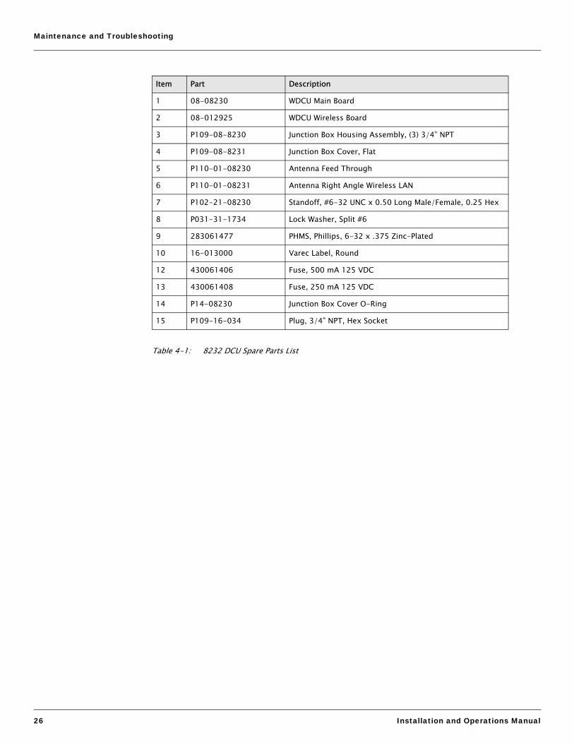
Table 4-1: 8232 DCU Spare Parts List
Item Part Description
1 08-08230 WDCU Main Board
2 08-012925 WDCU Wireless Board
3 P109-08-8230 Junction Box Housing Assembly, (3) 3/4” NPT
4 P109-08-8231 Junction Box Cover, Flat
5 P110-01-08230 Antenna Feed Through
6 P110-01-08231 Antenna Right Angle Wireless LAN
7 P102-21-08230 Standoff, #6-32 UNC x 0.50 Long Male/Female, 0.25 Hex
8 P031-31-1734 Lock Washer, Split #6
9 283061477 PHMS, Phillips, 6-32 x .375 Zinc-Plated
10 16-013000 Varec Label, Round
12 430061406 Fuse, 500 mA 125 VDC
13 430061408 Fuse, 250 mA 125 VDC
14 P14-08230 Junction Box Cover O-Ring
15 P109-16-034 Plug, 3/4” NPT, Hex Socket

Data Capture Unit
Varec, Inc. 27
Troubleshooting
Refer to Figure 4-2 to locate the 8232 DCU switches and LED indicators.
Using Local Diagnostics (LED Indicators)
1. Close DIP Switch SW1-1 to turn on local diagnostics, and then press Reset switch SW4. This activates the LED indicators as well as the local EIA232-C serial port.
2. Monitor the LED indications as described below.
Figure 4-2: 8232 DCU LEDs. Switches, and Fuses (Wireless Board Not Shown)
LED Purpose Indication Description
D1 Indicates operation status. This LED should toggle a few times per second during normal program operation.
D2 Indicates communication status. If the IntoPlane client is communicating to the 8232 DCU, this LED should toggle about once a second.
D3 Indicates pulse input status. If pulses are actively being received by either pulse channels 1 or 2, this LED will be on. When pulses stop on both channels, this LED will turn off. If the 8232 DCU is communicating with the LCR-II or EMR3 Electronic Meter Interface, this LED should toggle about once per second.
D5
R12
RESET
R16
5
SW4
J1
1 2 3 4 5 6 7 8
R13
U5
RevD1
3
4
U1
Z2
D4
GND
+5V
L1
TP2
Z4
910
21
J4
D2
R2
6
Q2U8
Z3
R6
C7
R1
+
-
U6
J6
R3
+Vin C6R14
U2
R4
R9
C5
C8
2
TP1
U3
Wireless DCU
SW1
J3
J5
Asse
mbl
y 01
2814
D3
R10
D6
R15
TP3
G
1
2
C10
180603
R5
U7
R7 C3
C9
F1
C4
R
1
C11
TModel 8230
C2
Q1
R11 U4
J2
R8
Q7
R21
F2
D9
J9
A
B
Serial No
OPEN
LEDs
Reset Switch SW4
Options & Address Switch (SW1) DIP Switches SW1-1 to SW1-8
Fuse 1
Fuse 2

Maintenance and Troubleshooting
28 Installation and Operations Manual
Returning the 8232 DCU to Factory Default Settings
To initialize all 8232 DCU configuration parameters to factory default settings:
1. Close DIP switches SW1-1 and SW1-2 and press RESET switch SW4. All three LEDs will appear yellow, and after a few seconds all LEDs will turn off. LED D1 should toggle about once per second.
2. Open DIP switch SW1-2.
Resetting the 8232 DCU
Press RESET switch SW4 to restart the 8232 DCU application program.
Replacing a Fuse
This section describes how to remove and replace the input power fuse (F1) or the output power fuse (F2).
! Warning Explosion Hazard. To prevent an ignition of a flammable atmosphere, do not disconnect Fuse 1 unless area is known to be nonhazardous.
! Warning To prevent an ignition of a flammable atmosphere, do not remove or replace Fuse 2 while circuit is live unless area is known to be nonhazardous.
1. Turn off the main circuit breaker switch to remove power from the unit.
2. Remove the 8232 DCU cover.
3. Disconnect the RF antenna cable from the 8232 Bluetooth and I/O Interface Board (see Figure 4).
4. Remove the four mounting screws from the 8232 Bluetooth and I/O Interface Board, and then remove the board.
5. Using needle-nosed pliers, remove the fuse on the 8232 DCU circuit board and replace it with a new fuse. To locate the fuse, refer to Figure 4-2.
6. Replace the 8232 Bluetooth and I/O Interface Board and fasten with the four mounting screws.
7. Connect the RF antenna cable to the 8232 Bluetooth and I/O Interface Board (see Figure 4-2).
8. Replace the 8232 DCU cover.
9. Turn on the main circuit breaker to connect power to the unit.

Varec, Inc. 29
5 Specifications
Primary Components
Safety Approvals (Pending)
Electrical
Switches, Indicators, and Connectors
8232 Data Capture Unit processor board Mitsubishi 16-bit microprocessor
8232 Bluetooth and I/O Interface Board Bluetooth wireless communicationRF connector for antenna feedthrough External 2.4 GHz antenna
Enclosure NEMA 4
Antenna 2.4 GHz external
Agency Reference
FM Approvals (FM) Class I, Division 2, Groups A – D
Canadian Standards Association (CSA) Class I, Division 2, Groups A – D
Input Power 8 – 36 VDC power required
Output Power Capacity 1 power output terminal for powering up to two external pulse transmitters or other devices
Output Power Options On-board, regulated +5 VDCSwitched connection to pulse transmitterRoute input power directly to pulse transmitter
Reset Switch Sends reset signal to processor
DIP Switch 8-position
Status Indicators 3 LEDs
Expansion Modules 16-pin connector
Serial Connector 1 - for digital communications with ViewRTU or electronic meter register

Specifications
30 Installation and Operations Manual
Pulse Input
Pulse Inputs Maximum 2
Pulse Voltage Range 3 to 30 Volts DC
Pulse Frequency Limit 30 KHz
Connection 4 position, plugable terminal block

Varec, Inc. 31
6 Ordering Information
Order Codes
Enclosure OptionsA0 NoneA1 NEMA 4
Factory Mutual Approvals (FM) (Pending)Class I, Division 2 Canadian Standards Association (CSA) (Pending)Class I, Division 2
A9 Special
N8232 Complete Product Designation

Ordering Information
32 Installation and Operations Manual


Varec, Inc. • 5834 Peachtree Corners East, Norcross (Atlanta), GA 30092 USATel: +1 (770) 447-9202 • Fax: +1 (770) 662-8939
www.varec.com
© 2006 Varec, Inc. All Rights Reserved. This document is for information purposes only. Varec, Inc. makes no warranties, express or implied, in this summary. The names of actual companies and products mentioned herein may be the trademarks of their respective owners.
Document CodeIOM100GVAE0809


