4P42 Section:
Related:
Title:
4.4
16
Emission Factor Evaluation Fiberglass Reinforced Plastic Open Molding
ERM-Northeast
June 1996
I I I I I I I I I I I I I I I I I I I
CONFIDENTIAL WORKING DRAFT
EMISSION FACTOR EVALUATION FIBERGLASS REINFORCED PLASTIC OPEN MOLDING
June 1996
Prepared for:
National Marine hkmufactums Association 3050 K St., NW WaSllingtOQ Dc m Prepared by:
EXhf-NORTHFAST 175 Froehlich Farm Boulevard Woodbury, New York 11797

I I I I 1 I I I I I I I I I I I I
CONFIDENTIAL WORKING D R A n
EMISSION FACTOR EVALUATION FIBERGLASS REINFORCED PLASTIC OPEN MOLDING
June 1996
Prepared for:
National Marine Manutamues Association 3050 K St., NW Washington, Dc uMo7
Prepared by:
ERM-NORTHEAST 175 Fmehlich Farm Boulevard Woodbury, New York 11797
10890016.747
1 I

'1 I
TABLE OF COZVTEIVTS
I I I I 1 1 I I 1 I I I 1 I I I I
1.0 INTRODUCZZON
1.1 PROfiCT SCOPE
1.2 REPORT ORGANIZATION
2.0 EMISSIONFACTOR DEVELOPMENT AND GENEXAL APPLICABILITY TOFRPMNWLFACTURlNG
3.0 BOAT BUILDING
3.1 GENERAL INDUSTRY DIFORMATION
3.2 DESCRIPTION OF THE TYPICAL BOAT PLANT
4.0 FRP OPEN MOLDING EMISSION FACTORS
4.1 DESCRIPTION OFlNFORAMTIONREVKWED 4.1.1 AP-42 Re@ence Documents 4.1.2 €PA F R P Open Molding Discussion Document Re@enm 4.1.3 Additional F R P Open Molding Emission Studies
EVALUATION OF OPEN MOLDING EMISSION FACTORS AND THElR APPLICXBLUTYTO BOAT BUILDING 4.2.1 4.2.2 4.2.3 4.2.4 OtherFactorsAfi&.ng Emissions
4.2
Overall Quality The Souroe Documents Scale and Size of the Proam Being Tested Product Being Fabricated and the FRP Fabrimtion Process
5.0 CONCLUSIONS
1 - 1
1 - 1
1 - 2
2 - 1
3 - 1
3 - 1
3 - 2
4 - 1
4 - 1 4 - 1 4-13 4-15
4 -16 4-17 4 -31 4 -32 4-32
5 - 1
i
I I I I I I 1 I I I I I 1 I I I I I I
LIST OF TABLES
41 NMMA Emission Factor Evaluation Descriptzon of Eniission Factor R e f m s
MMMA Emission Factor Evaluation Comparison of Emission Factors for Resins aid Gel Coats
FRP Open Molding Emission Factor Evaluation Products Evaluated in Reference Documents
4 2
4 3
4 4 Emission Factor Evaluation Comparison of R€P Open Molding Parameten
FRP Open Molding Emission Factor Evaluation Detailed Product Line Emission Factors
4 5
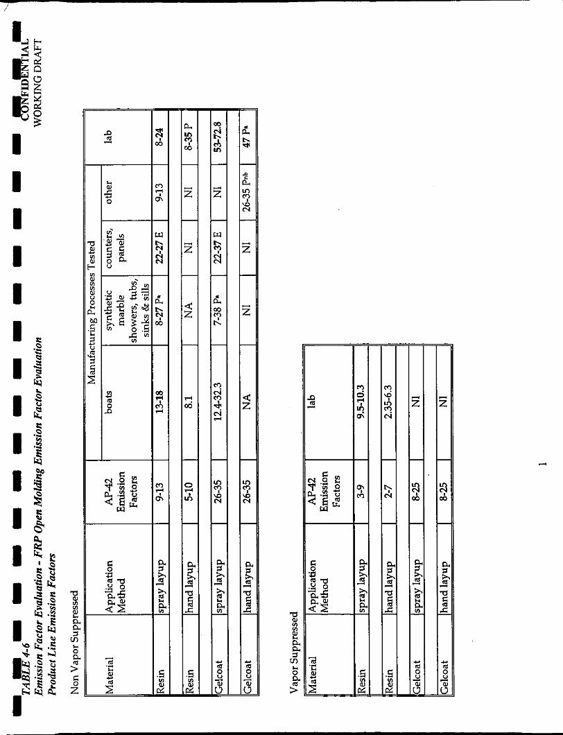
4 6 Emission Factor Evaluation - FRP Open Molding Emission Factor Evaluation Product Line Emission Factors
4 7 RTI’s Comparison of EPAAP-42 Emission Factors and Emission Factors Devisedfrom Other Resin Test Results (in %AS) Emission Factor Evaluation - €RP Open Molding
RTI% Comparison of EPAAP-42 Emission Factors and Eniission Factors Derivedfrom Other Gelcoat Test Results (in %AS) Emission Factor Evaluation - €RP Open Molding
4 8
.. 11

I LIST OF APPENDICES
I APPENDMA: Bibliogmphrj
APPENDM B: Emission Factor Calculations 1 I I I 1 1 I I I I I I I I I I I iii
I I I I I I 1 I I I I I I I 1 I I I I
LIST OF ACRONMMS
A a AAA As BPO C C(S) ARB CFA CFM CM DGC DOW E EF EM EPA ERM FRP G GE Grav m HVLP LP Ls LSE MACT MC MNTAP NA NB NI NIOsH NMMA NP N V S 0-D OSHA P PHS R RAn RTI
- Air Emission Measurement Method - Method of Measurement Not Provided - Air-Assisted Airless Spray Gun - Available Styrene - Benzoyl Peroxide - Calculated - California (State) Air Resources Board - Composite Fabricators Association - Cubic Feet Per Minute - Closed Molding - Diacid Glycol Condensate - DOW Chemical - Estimated Emission Factor - Emission Factor - Emission Measurement - Environmental Protection Agency - ERM-Northeast, Inc. - Fiber Reinforced Plastic - Gravimetric Method - Gelcoat - Gravimetric Measurement - HandLapp - High Volume Low P~ssure Spray Gun - LowProfileResin - Low Styrene Resin - Low Styrene Emission Resin - Maximum Achievable Control Technology - Marble Casting - Not Used in Boat Manufacturing - Minnesota Technical Assistance Program - Not Applicable - No Testing Provided to Substantiate Emission Factor - NoneIdentified - National Institute of Occupational Safety and Health - National Marine Manufacturing Association - NotProvided - Non-Vapor Suppressed - Ortho/Dcpd Mixed Resin Base - Occupational Safety and Health Administration - Emission Factor provided - Public Health Service - Resin - Reasonably Available Control Technology - Research Triangle Institute
iv

I LIST OF ACRONMMS (continued)
I s SAI SCAQMD
1 SL SRI TWA
I VOC I VS vsw X 1
I' I I I 'I I I 'I 'I
- Styrene Emissions - Science Applications, Inc. - South Coast Air Quality Management District - Spray Layup - Southern Research Institute - Time Weighted Average - Volatile Organic Compound - Vapor Suppressed - Vapor Suppressed and Wax - Emission Factor Determined Elsewhere
'I
I V
I I I I I I 1 I I I I I I I I I I I
CONFIDENTIAL WORKING DRAFT
EXECUTNE SUMi'kMRY
The U.S. Environmental Protection Agency @PA) has prepared and
distributed a document titled, A Discussion of the Present AP-42 Factors
Underestimatinp VOC (or Monomer Evaporative) Emissions for Polvester
Resin Material Operation, which was based on a study conducted by
Research Triangle Institute (Rn). The document concluded that the current
EPA AP42 FRP open molding emission factors underestimate FRP fabrication emissions by a factor of two. This document also referenced
additional emission studies being conducted by the Composite Fabricators
Association (CFA) and Dow Chemical.
The National Marine Manufacturefs Association (NMMA) has retained ERM
to conduct an evaluation of the emission factors associated with FRP open
molding operations in response to this EPA document. The objectives of this investigation were to:
. assess the validity of the AP42 emission factors developed for FRP open molding processes;
assess the validity of RTI's claims regarding emissions from FRP open molding processes;
evaluate the emission factors developed by RTI, CFA and DOW;
evaluate whether the AP-42, RTI or other referenced open molding FRP emission factors are representative of boat building FRP operations; and
identify repmentative emission factors for the boat building FRP industry.
.
.
.
. ERM also reviewed all the emission studies and their associated documents,
which were refemnced in the EPA document
I ERM-NORTHEAST E-1 1089001 6.747flcnrn
I I I I I I 1 I I I I I I I 1 I 1 I I
CONFIDENTIAL WORKING DRAET
The following conclusions were reached:
the emission factors derived from the AP-42 and the EPA discussion documents are not representative of boat building FRP open molding fabrication processes;
the boat plant emission factors are generally within the AP-42 emission factor ranges;
insufficient information was available to accurately estimate emissions factors using the EPA Discussion Document References;
neither the RTI Report nor its support documents demonstrate that the AP42 emission factors underestimate FRP full-scale fabrication emissions by a factor of two;
labscale and bench-scale studies, as well as small FRP fabrication studies, are not representative of the boat building process and generally overestimate boat building emission factors;
the size and shape of boat molds results in less overspray and consequently lower process emissions than fabrication of products using small, flat and/or convex molds; and
differences in raw materials, operating parameters (e.g., application technique, curing time and gel time) and fabrication process (e.g., heated curing) significantly affect FRP open molding emission factors.
ERM-NORTHEAST ES-2 1089W16.747/lcAm
I I I I 1 I I I 1 I I I I I I I I 1 I
1.0
1.1
CONFIDENTIAL WORKING D m
INTXODUCTLON
ERM-Northeast, Inc. (ERM) was retained by the National Marine
Manufacturers Association (NMMA) to conduct an evaluation of emission
factor for fiberglass reinforced plastic (FRP) open molding. This document
has been prepared to summarize the procedures, results and conclusions of
this emission factor evaluation.
PROJECT SCOPE
Following the first boat manufacturing presumptive "maximum
achievable control technology" (MACT) meeting, Madelaine Strum, US. Environmental Protection Agency (EPA) prepared and distributed a
discussion document titled, A Discussion Of The Present AP-42 Factors
Underestiinating VOC (Or Monomer Evaporative) Enrissions For Polyester
Resin Material Operution, November 1995. Preparation of this document
had been requested at the presumptive MACT meeting by meeting
participants.
According to this discussion document, Research Triangle Institute (RTI)
had completed a study for EPA which concluded that the current EPA
AP-42 FRP open molding emission factors underestimate FRP fabrication
emissions by a factor of two.
Emission factors for FRP open molding are provided in W o n 4.12
Polyester Resin Plastics Product Fabrication, of EPA's AP42 document,
Compilation of Air Pollutant Emission Factors, Volume I: Stationary Point and Area
Sources. This document contains emission factors for numerous industrial
processes. However, these emission factors are averages of all emissions data
for the selected process and generally do not take parameters effecting
emissions (e.g., temperature, etc.) into account (EPA, 1985).
ERM-NORTHEAST 1-1 1089001 6.747~cnm

I I I I I I 1 I I I I I I I 1 I I I I
1.2
CONFIDENTIAL WORKING DRAIT
In addition to the RTI report, the EPA discussion document also
referenced additional FRP fabrication emission studies being conducted
by the Composite Fabricators Association (CFA) and Dow Chemical.
As a response to this discussion document, NMMA retained ERh4 to perform
an emission factor evaluation for FRP open molding operations. The
objectives of this study were to:
. assess the validity of the AP-42 emission factors developed for FRP open molding processes;
assess the validity of RTI's claims regarding emissions from FRP open molding processes;
evaluate the emission factors developed by RTI, CFA and DOW;
evaluate whether the AP-42, RTI or other referenced open molding FRP.emission factors are representative of boat building FRP operations; and
identify representative emission factors for the boat building FRP industry.
.
.
In addition to the EPA discussion document, the RTI report and their source
documents, other FRP open molding fabrication emission studies, including
but not limited to boat building emission studies, were reviewed. A
s u m m a r y of the documents reviewed for this emission factor evaluation is
presented in Appendix A to this document, the Bibliography.
REPORT ORGANIZATION
This evaluation is organized into the following sections:
Section 2.0: Emission Factor Development And General Applicability To FRP Manufacturing
~~
ERM-NORTHEAST 1-2 1089001 6.74lnc4m
I I I I I 1 I I 1 I I I I I I I I I 1
CONFIDENTIAL WORKING DRAFT
Section 3.0: Boat Building (general boat building industry information, typical boat plant)
FRP Open Molding Emission Factors (emission studies reviewed, evaluation of emission factors)
Section 4.0
Section 5.0: Conclusions and Recommendations
ERM-NORTHEAST 1-3 i 089001 ~ 4 7 n c n m

I I I I 1 I I I I I I I I I I I I I I
20
CONFIDENTlAL WORKING DRAIT
EMISSION FACTOR DEVELOPMENT AND GENERAL AppLIcABILITy TOFRPMANUFACIURWG
As previously discussed, EPA has compiled emission factors for numerous
industrial processes in their AP-42 document This document was originally
based on a Public Health Service (PHS) Publication, No. 999-AP-42, by the
same name. The PHS document was revised by EPA and four new editions
were published in 1972,1973,1976 and 1985. In September 1988, Supplement
B to the fourth edition of AP-42, which provided emission factors for the
polyester resin plastic products fabrication, was issued by the EPA.
AP-42 emission factors, which were generated using average emission rates
for selected process, generally did not take parameters effecting emissions
(e.g., temperature, etc.) into account (EPA, 1985). As a result, the AP-42
emission factors are insensitive to process variations that affect emissions and
to the variability within industries included in an AP-42 source category.
Consequently, emission factors are not suited for estimation of facility
emissions, but are more appropriate for estimation of overall emissions from
a number of sources, such as emissions inventory efforts. Although the AP42
emission factors are not a higher accurate estimation tool, they are routinely
used by rrgulators and industries to estimate air emissions at individual
facilities.
AP-42 emission factors are generally expressed as the weight of the air
pollutant divided by either the unit weight or volume of the source material
or the distance or duration of the activity. For polyester resin plastic products
fabrication, emission factors are presented as pounds of styrene emitted per
pound of available styrene. This measurement technique normalizes
emission estimates based on the styrene content of the raw materials used
(e.g., resin and gelcoat).
ERM-NORTHEAST 2-1 lM)90016.747ilMm

I I I I I I 1 I I I I I I I I I I I I
3.0
3.1
CONFIDENTIAL WORKING DRAFT
BOAT BUTLDING
Tlus section provides general information regarding the boat building
industry and a description of the "typical" boat building plant Information
contained in this section was obtained from the NMMA Member Survey - MACT Floor Detemrinatiunfur Fiberglass Boat Manufacturing (NMMA, 1996).
This survey response, which contains information submitted by NMMA
members, contains production information for the year 1994.
GENERAL INDUSTRYlNFORMATION
Numerous boat building plants are located in the U.S.. The majority of these
plants are located on the northwest, southwest and southeast coast. The
NMMA survey classified boat plants according to the total number of full- time equivalent employees as follows:
Mlnimum: 11-25 Average: 751-1,000 Medium: 1,001-1,500 Maximum: >1,500
Boat building facilities range in size from under 100 to over 1,500 full-time
employees and manufacture a variety of FRP sail boats and power boats.
Boats range in size from ten feet to over seventy feet and from six to twelve
feet in width. The majority of boat plan& in the U.S. employ over 1,500
production workers. Boats plants work on varied shift and work schedules.
The majority of boat manufadured in 1994 were between 14 and 25 feet long.
(NMMA, 1996)
The two main VOC-containing raw materials used to build boats are resin
and gelcoat The largest quantity of resin used in boat manufacturing is
nominal bulk resin which contains from 32-36% styrene. Smaller quantities of
tooling resin (3652% styrene), nominal bamer coat resin (20-31% styrene)
ERM-NORTHEAST 3-1 1089W16.747/lc/tm
I I I I I I I I I I I I I I I I I I I
CONFIDENTIAL WORKING DRAFT
and putty and gunk (12-19% styrene) are also used. Gelcoats used at boat
plants can be either solely styrene based (29-38% styrene) or can also contain
come methyl methacrylate (26-50% styrene and 3-9% methyl methacrylate).
Smaller quantities of initiators are also used. The two main initiators used are
MEKP type and Benzoyl Peroxide (100%). MEKP-type catalyst contains 2-5%
methyl ethyl ketone and 32-52% dimethyl phthalate. (NMMA, 1996)
Peak resin usage ranges from 4 tons per month for minimum boat plants to
210 tons per month for maximum plants. Gelcoat usage ranges from 0.55 tons
per month for minimum plants to 42 tons per month for maximum plants.
(NMMA, 1996)
Boat builders mainly utilue a variety of FRP open contact molding methods
for application of gelcoat and resin. For application of gelcoat, all survey
respondents use spray guns and 15% also use brushes. For resin application,
90% use spray guns, 88% use chopper guns, 12% use pressure rollers, 15%
use flow coaters and 66% use a combination of handlayup and spray guns. In
addition, some builders also use non-open contact molding methods for resin
application, 8% use resin transfer, 15% use bag molding and 6% use other
molding methods (eg., foam injection, cold press and vacuum bags).
(NMMA, 1996)
With regard to resin application equipment, 90% use spray guns, 88% use
chopper guns, 12% use rollers and 15% use flow coaters. As demonstrated by
the above responses, operations at individual boat plank are extremely
varied; an individual boat builder may use a combination of molding
techniques and associated application equipment at their facility for
application of FFW raw materials. (NMMA, 1996)
Air flow rates for lamination areas, spray booth and other shops and booths
vary widely. Ventilation rates range from 70,000 cfh (minimum plants) to
ERM-NORTHEAST 3-2 I 089001 6.7mcnrn

I I I I I I I I I I I I I I I I I I I
3.2
CONFIDENTIAL WORKING DRAm
280,000 cfm (maximum plants) for lamination areas; from 750 cfm (minimum
plants) to 215,000 cfm (maximum plants) for spray booths; and from 1,125
cfm (minimum plants) to 104,000 cfm (maximum plants) for other shops and
booths (e.g., mold, fabrication, wood, grinding, parb inspection). Most plants
have gel spray, lamination, paint and grinding booths. (NMMA, 1996)
DESCRIPTION OFA TYPICAL BOATBUILDING PROCESS
The following is a typical process used to manufacture high-volume
production-model FRP power boats using open molding techniques:
1. The boat mold is brought out of storage, cleaned, repaired, if necessary, and waxed.
2. The waxed mold is placed within the gelcoat spray booth and a thin layer of gelcoat sprayed onto the open surface of the waxed mold. (If necessary the coated mold is placed beneath heat lights to accelerate gelcoat curing.)
3. The gelcoated mold is moved to another spray booth where the first layer of reinforced resin, the skin coat, is applied with a chopper gun.
4. During or immediately after application of the skin coat, workers manually roll down the applied laminate to remove trapped air bubbles.
5. Steps 3 and 4 are repeated until the desired boat wall thickness is achieved and the coated mold is left to cure.
6. Pre-fabricated wooden supports and other structural pieces are laminated into the part using the chopper gun.
7. After the part has been cured to an acceptable strength level, it is removed from the mold and the mold is returned to storage.
8. The boat is finished using grinding, sanding gluing, coating, painting and other final assembly operations.
ERM-NORTHEAST 3-3 1089001 6.747/lcitm

I I I I I I I I I I I I I I I I I I I
CONFIDENTIAL WORKING DRAFT
4.0 FRP OPENMOLDING EMZSSION FACTORS
This section provides a description of the FRP open molding emission factor
sources reviewed along with an evaluation of the validity of these sources
and their applicability to boat building FRP open molding operations.
4.1
4.1.1
INFORMATION REVIEWED
Three groups of information were reviewed for this FRP open molding
emission factor evaluation. They include:
1. AP-42, Compilation of Air Pollutant Emission Factors, Volume I: S t a t i o n q Point and Area Sources, and its source documents;
2 EPA FRP open molding discussion document A Discussion Of The Present AP-42 Factors Underestimating VOC (Or Monomer Evaporative) Emissions For Polyester Resin Material Operation, and its referenced studies; and
3. additional FRP open molding emission studies and related documents.
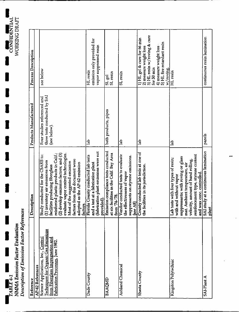
A listing of these documents is provided in the Bibliography contained in
Appendix A of this report In addition, an overview of these documents,
which includes the document description, type of emission study, product
fabricated and a description of the FRP fabrication process, is presented in
Table 4-1.
AP-42
As discussec. -I Section 2.0, emission factors for polyester min ~ - - s t i c
products fabrication were incorporated into A P 4 in September 1988. These emission factors addressed the following FRP fabrication processes: hand
layup, spray layup, continuous lamination, pultrusion, filament winding,
marble casting and closed molding.
ERM-NORTHEAST 4-1 lM)9W16,747/lCllm
I I I I I I I I I
Process Hand Layup Spray Layup
CONFIDENTIAL WQRKMG DRAFT
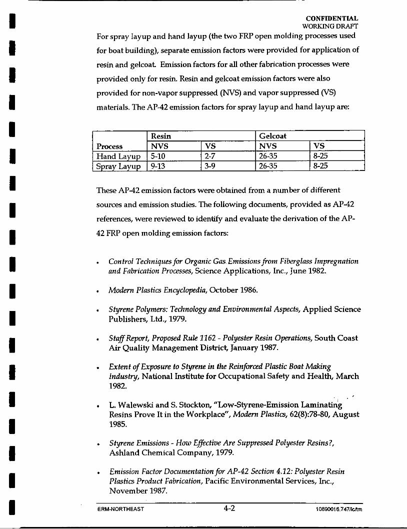
For spray layup and hand layup (the two FRP open molding processes used
for boat building), separate emission factors were provided for application of
resin and gelcoat Emission factors for all other fabrication processes were
provided only for resin. Resin and gelcoat emission factors were also
provided for non-vapor suppressed ( N V S ) and vapor suppressed (VS)
materials. The AP-42 emission factors for spray layup and hand layup are:
Resin Gelcoat N V S VS NVS VS 5-10 2-7 26-35 8-25 9-13 3-9 26-35 8-25
These AP42 emission factors were obtained from a number of different
sources and emission studies. The following documents, provided as AP42
references, were reviewed to idenhfy and evaluate the derivation of the AP-
42 FRP open molding emission factors:
Control Techniquesfor Organic Gas Emissions from Fiberglass Impregnation and Fahcation Processes, Science Applications, Inc., June 1982.
Modem Plastics Encyclopedia, October 1986.
Styrene Polymers: Technology and Environmental Aspects, Applied Science Publishers, Ltd., 1979.
Staff Report, Proposed Rule 11 62 - Polyester Resin Operations, South Coast Air Quality Management District, January 1987.
Extent of Exposure to Styrene in the Reinfhczd Plastic Boat Making Industry, National Institute for Occupational Safety and Health, March 1982.
L. Walewski and S. Stockton, “Low-Styrene-Emission Laminating Resins Prove It in the Workplace”, Modern Plastics, 62(8):78-80, August 1985.
Styrene Emissions - How €fictive Are Suppressed Polyester Resins?, Ashland Chemical Company, 1979.
Emission Factor Documentation for AP-42 Section 4.12; Polyester Resin Plastics Product Fabrication, Pacific Environmental Services, Inc., November 1987.
I ERM-NORTHEAST 4-2 1089~16.747ncnm
I I I I I I I I I I I I I I I I I I I
CONFIDENTIAL WORKING DRAfT
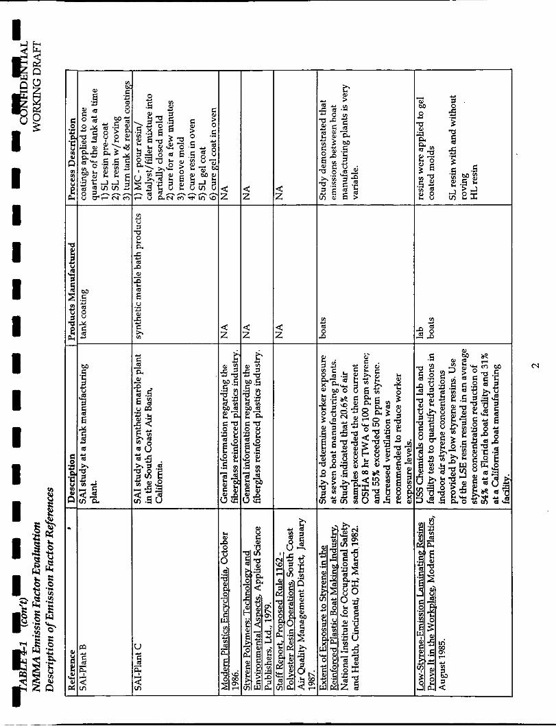
A complete bibliography of these documents is presented in Appendix A and
document overviews are presented in Table 41. In addition, the emission
factors identified in these documents along with the associated FRF product
fabricated is provided in Table 42.
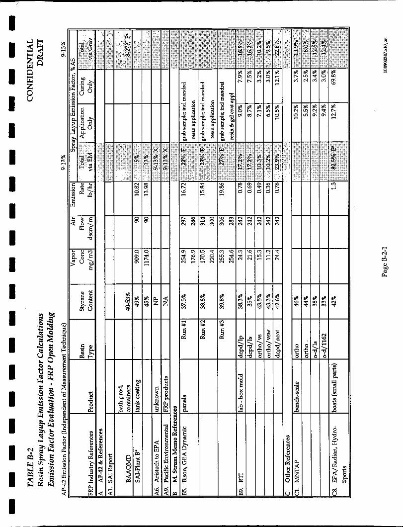
The emission factors for spray layup of gelcoat and spray layup of resin were
both obtained from the above-referenced study conducted by the Science
Applications, Inc. (SAI). Ths document contained a review of available
emission data for fiberglass fabrication processes and the results from
emissions studies conducted by SA1 to determine emissions factors.
The emission factor for spray layup of gelcoat was obtained from a study
conducted by SA1 at a synthetic marble bathroom products fabrication
plant, identified as Plant C. This emission factor, 26%-35% of available
styrene (AS) for spray application of gelcoat, was considered by SA1 to be
the upper bound limit since the emissions measurement collected may
have also included emissions from resin pouring and curing. The
emission factor for spray layup of resin (ie., 9%-13%AS) was obtained
from a study conducted by SA1 at a tank coating plant, identified as Plant
B. A description of the fabrication processes used at Plant B and Plant C
are provided in Table 4-1.
SA1 recommended use of the Plant B and Plant C emission factors since
they considered them to be more accurate than the emission factors
derived from the available studies. Because the majority of the available
studies were old and were not conducted with the intention of developing
emission factors, information needed to develop emission factors (i.e.,
styrene content) and to evaluate the reliability of the information
(emission measurement techniques) were not always available and had to
be assumed.
ERM-NORTHEAST 4-3 1089~16.747ncltm

I I I I I I I I I I I I I I I I I I I
CONFIDENTIAL WORKMG D m
In addition to the spray layup, emission factors for hand layup FRP
fabrication processes also recommended by SA1 in their study (SAI, 1982).
SAPs selected gelcoat hand layup emission factor (Le., 47%AS) was
obtained from a lab test conducted by Shasta County, and SAPs selected
resin hand layup emission factor (i.e., 16%-35%AS) was obtained from a
lab test conducted by Kingston Polytechnic, England.
Although both of the SA1 hand layup emission factors were originally
proposed as the AP-42 emission factors, these values were not adopted
(Pacific Environmental Services. Instead, hand layup emission factors for
both resin and gelcoat provided by Aristech Chemical Corporation,
Polyester Unit, were adopted (Pacific Environmental Services, 1987).
In a letter to EPA regarding the proposed AP-42 emission factors, Aristech
recommended alternate emission factors for hand layup emissions.
Aristech commented that the hand layup emissions for gelcoat application
could not greater than those for spray layup and thus the hand layup
emission factor should be at least equal to the spray layup emission factor
(i.e., 26%-35%AS). In addition, Aristech also commented that according
their studies, emission factors for hand layup application of resins were
closer to 5%-10%A!3 than 16%-35%AS. The basis of Aristech's resin hand
layup emission factor appears to be laboratory testing conducted by
Ashland Chemical Company (Ashland, 1979). Both of the k s t e c h
recommended values were adopted as the AP-42 emission factors.
In conclusion, the AP-42 emission factors are based on emission testing
conducted at a synthetic marble bathroom products fabrication plant
(gelcoat spray layup), a tank coating plant (resin spray layup), and a
resin manufacturer's lab (resin hand layup). The emission factor for
gelcoat hand layup is not based on an emission study, but rather a
recommended value. In addition to the SA1 tests and the tests conducted
by Shasta County and Kingston Polytechnic, the SA1 document also
~
ERM-NORTHEAST 4-4 10890016.747ncnm

I I I I I I I I I I I I I I I I I I I
42.2
CONFIDENTIAL WORKING DRAFT
contains emission studies for other bathroom product fabrication plants
and laboratory tests.
Additional discussion regarding the selected AP-42 emissions factors and
their applicability to boat building FRP open molding activities is
presented in Section 4.2.
EPA FRP Open Molding Discussion Donanent Referents
As discussed in Section 1.1, following the first boat manufacturing
presumptive MACT meeting, the USEPA distributed a discussion
document addressing emissions from fiberglass fabrication processes.
According to this discussion document, a study conducted by RTI in
cooperation with EPA indicated that the current EPA AP-42 FRP open
molding emission factors underestimate process emissions. As part of
their study, RTI reviewed existing emission studies for various FRP
fabrication plants, conducted lab tests to generate open molding emission
factors and compared their emission factors to the EPA AP-42 emission
factors. A summary of RTI's study is presented in Evaluation of Pollution
Prevention Techniques To Reduce Styrene Emissionsfrom Open Contact
Molding Processes, Draft Report, September 1995 (RTI, 1995).
The following emission studies referenced in the November 1995 EPA
discussion document and in the RTI report have been reviewed.
. Draft Project Report, Evaluation of Pollution Prevention Techniques To Reduce Styrene Emissionsfrom Open Contact Molding Processes, RTI, September 1995;
Composite Fabricators Association, Open Molding Styrene Emissions Study: Overviau and Summary of Hand Lay-up Emissions Study, 1995;
Radian Corporation, Determination of Styrene Emissionsfrom the Cultured Marble and Sink Manufacturing Industry, Final Report, Venetian Mmble, Richmond, VA, prepared for USEPA Emission Measurement Branch, April 1992;
.
.
ERM-NORTHEAST 4-5 10890016.747/l~m
I I I I I I I I I I I I I I I I I I I
4.1.3
CONFIDENTIAL WORKING DRAFT
. Radian Corporation, Determination of Styrene Emissionsfrom the Cultured Marble and Sink Manufacturing Industry, Final Report, General Marble, Lincolnton, NC, prepared for USEPA Emission Measurement Branch, August 1992;
Demonstration of Capture and Control EfFciencyfor a Styrene Emission Source, Cortec Facility, Radian and IT Corp., 1994; and
Bison Engineering, Emission Compliance Test, Styrene and Visible Emissions: Fiberglass Reinforced Plastic Lay-up Facility, Idaho Permit to Construct 860-0035, August 1993.
.
.
A complete bibliography of these documents is presented in Appendix A and
document overviews are presented in Table 4-1. In addition, the emission
factors i d e n ~ e d in these documents along with the associated FRP product
fabricated is provided in Table 4 2 .
The RTI report included RTI's evaluation of available emission data for
fiberglass fabrication processes and the results from emissions studies
conducted by RTI to determine spray layup emissions factors. RTI's study
involved lab-scale testing of various resin and gelcoat formulations using
box molds and varying operating parameters. Studies referenced in RTI's document (Le., Venetian Marble, General Marble, Cortec and Bison)
involved emission testing during FRP fabrication processes for synthetic
marble bathroom sinks, panels and pipes. The CFA study evaluated hand
layup emission factors in a laboratory setting.
Discussion regarding the applicability of RTI and CFA's studies to boat
building as well as RTI's evaluation of the current AP42 emissions is
presented in Section 4.2.
Additional FRp Open Molding Emissions Studies
Additional FRP open molding emission studies were also reviewed to
evaluate the appropriateness of the AP-42 and RTI derived emission factors
ERM-NORTHEAST 4-6 1089001 6.747iknm

I I I I I I I I 1 I I I I I I I I I I
CONFIDENTIAL WORKING D W
for application to boat building FRP open molding processes. %me of the
emission studies were conducted at boat plants. Following is a listing of the
additional documents reviewed:
. Minnesota Technical Assistance Program (MNTAP), Reducing Styrene Emissions in Fiber Reinforced Plastic Operntions, March 1993;
Radian Corporation, Volntile Orgnnic Cottipound Control nt Specific Sources in Louisville, KY nnd Nnskville, TN, prepared for EPA, December 1981;
Boat Plant A Emission Study, 1989;
Boat Plant B Emission Study, 1989;
Boat Plant C Emission Study, 1988;
Boat Plant D Emission Study, 1992;
USEPA, Guides to Pollution Prevention, The Fiberglass-Reinforced and Cotnposite Plastics Industry, October 1991;
Radian Corporation, Locating nnd Estittinting Air Emissionsfrom Sources of Styrene, Interim Report, prepared for EPA, October 1991; and
USEPA, Assessment of VOC Emissionsfiorn Fiberglass Boat Manufacturing, May 1990.
A complete bibliography of these documents is presented in Appendix A and
document overviews are presented in Table 4-1. In addition, the emission
factors identified in these documents along with the associated FRP produd
fabricated is provided in Table 42
The MNTAP study involved bench-scale testing at a full-scale FRP fabrication facility. The Radian study and the emission studies for Plants A, B
and C were conducted at full-scale boat building plants. In contrast, the
emission study for Plant D, a full-scale facility, involved lab-scale testing. The
last three documents listed provide only general FRP fabrication information
and/or contain emissions estimates based on the AP-42 emission factors.
ERM-NORTHEAST 4-7 1089001 6.747nm
I I I I I I I I I I I I I I I I I I I
CONFIDENTIAL WORKING DRAFT
4.2 EVALUATION OF FRP OPENMOLDING EMISSION FACTORS AND THELR APPLICABIL.lTY TO BOAT BUILDING
A number of different factors effect emissions from FRP processes. The
validity of the FRP open molding emission factors and their applicability
to boat building were determined by comparing the following
information obtained from the source emission studies:
. overall quality and adequacy of emissions-related information;
scale and size of the process being tested;
product fabricated and the associated FRP fabrication process; and
.
. other factors affecting emissions: - resin type and catalysc - applicator, application techtuque; - curing time and gel time; - emission measurement technique and procedures; - laminate thickness; and - facility size, air flow rates and temperature.
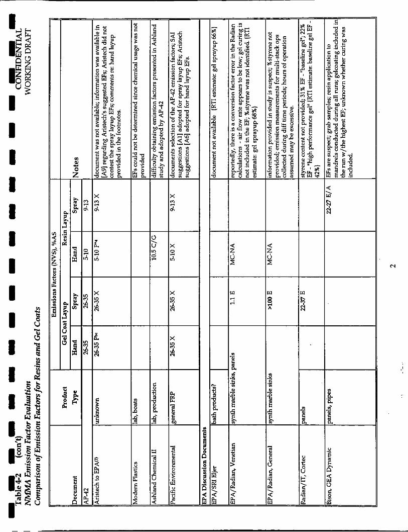
To facilitate evaluation of this information, a number of summary tables
were developed. A summary of the FRP products fabricated during these
emission studies is provided in Table 4-3; a summary of the above listed
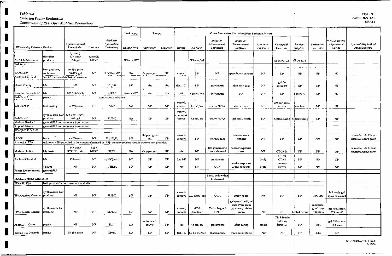
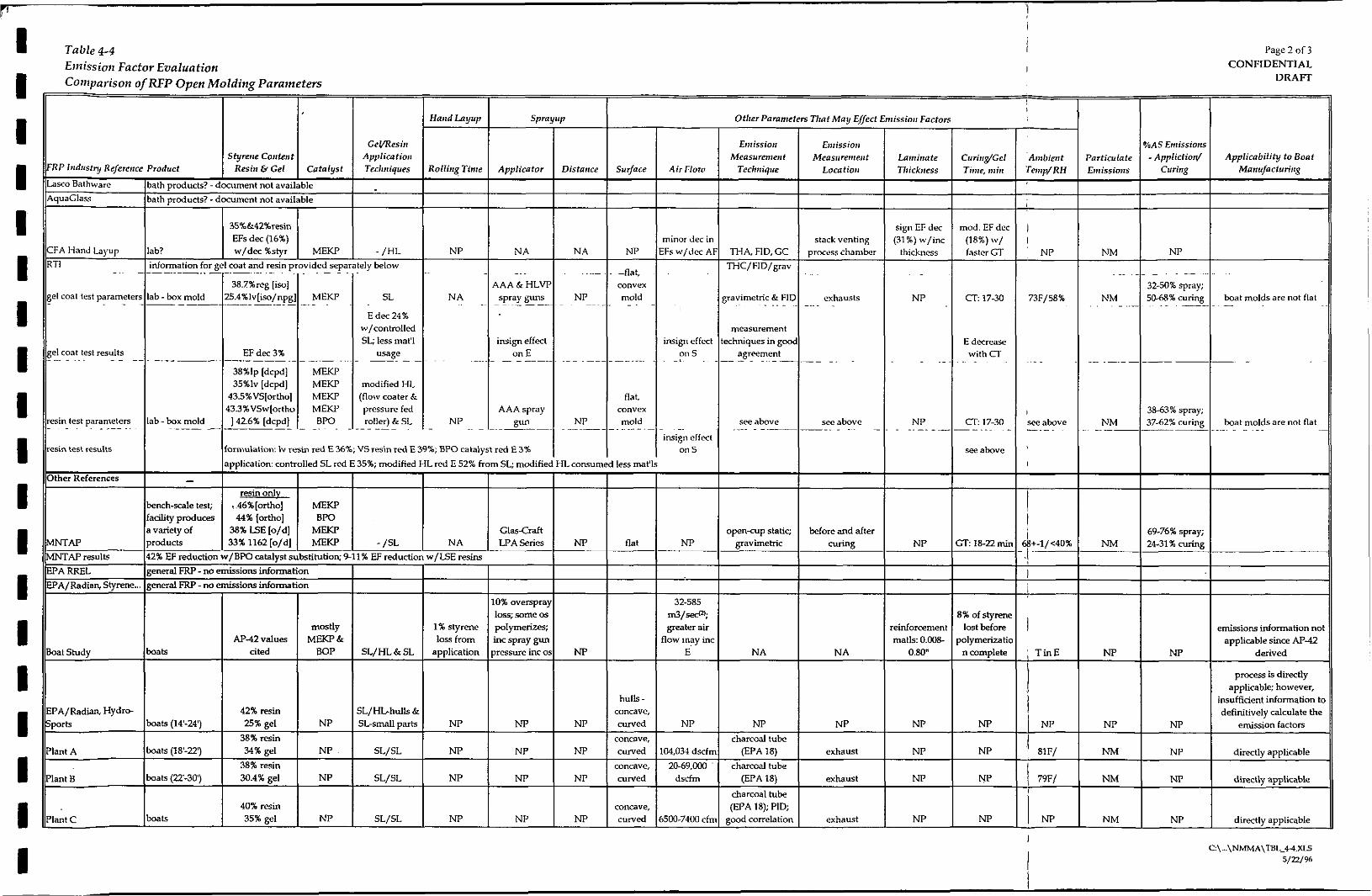
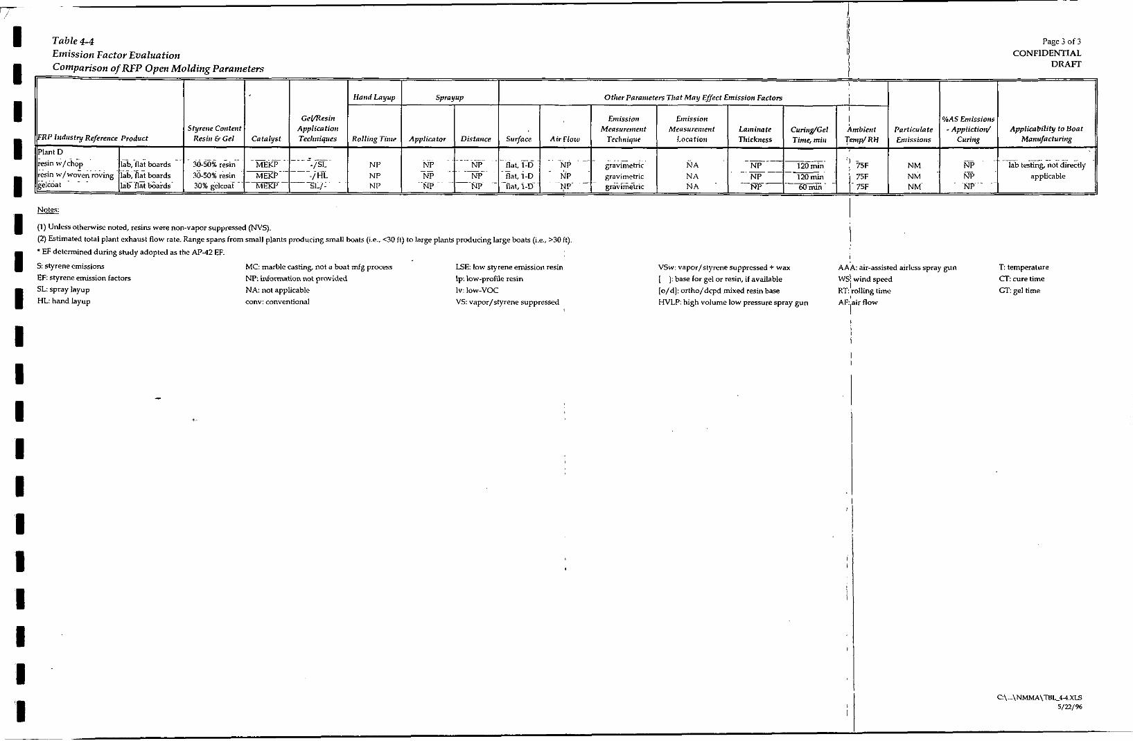
parameters that may affect emissions is provided in Table 44; a listing of
emission factors for each source document according to fabrication
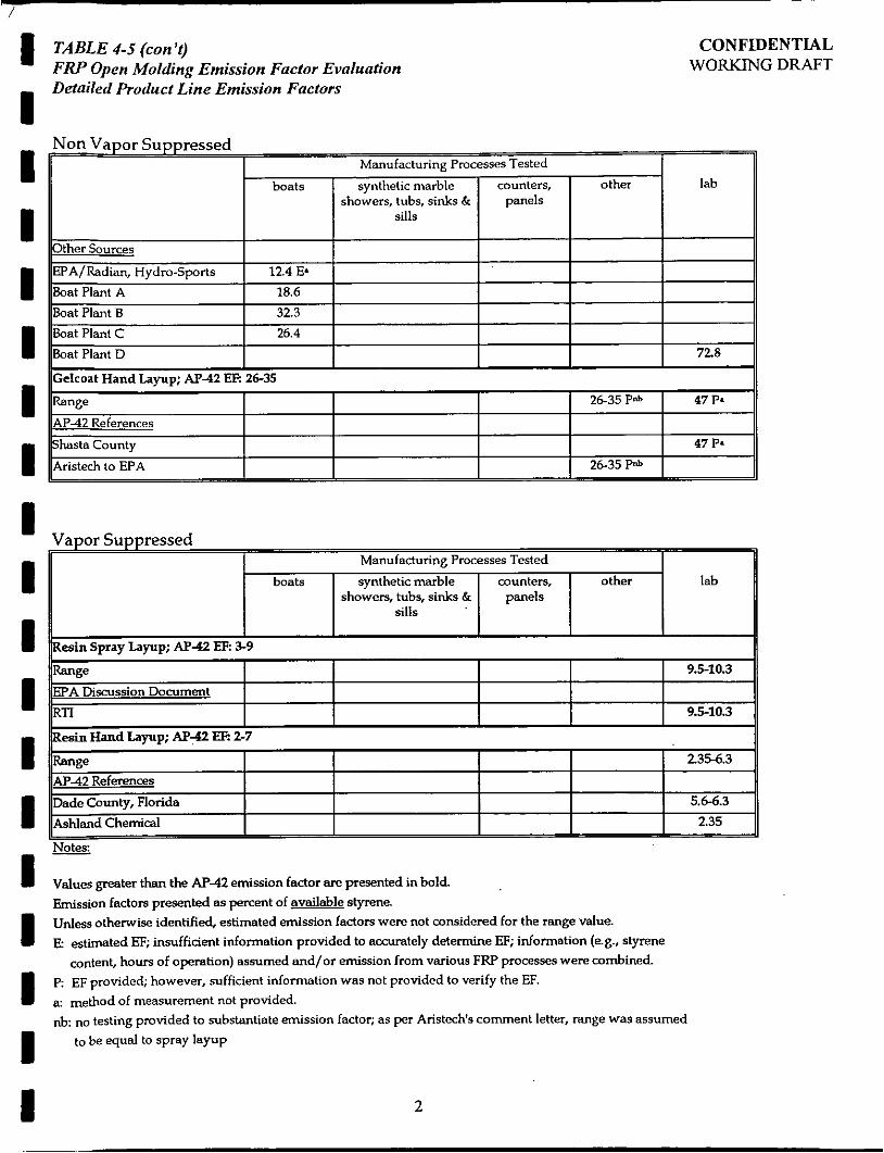
process and product is provided in Table 4-5; and a summary of emission
factors according to product is provided in Table 4-6.
4.2.1 Overall Quality the Source Documents
AP-42 Emission Factors
The development of the AP-42 spray layup emission factors in the SA1
report was fairly well documented. Adequate information (e.g., emission
rates, raw chemical usage, styrene content) was collected during the SA1
ERM-NORTHEAST 4-8 1089001 6.747AcAm

I 'I
CONFJDENTIAL WORKING DRAFT
studies to estimate spray layup emission factors for the product
fabrication processes being tested (i.e., spray layup and curing of gelcoat
outer coating on cured sinks and spray layup of resin tank coating).
However, because sample collection for Plant C was not well controlled,
non-gelcoat spray layup processes may have also been sampled.
Consequently, the gelcoat spray layup emissions for Plant C may have
been overestimated. The emission factor for Plant C is therefore qualified
with an " E . (Note: all emission factors requiring assumption of
information not provided or incorporating emission from other processes
are qualified in the tables with an " E . )
Development of the hand layup emission factors was not well
documented. Sufficient information was not provided in the Ashland
report to confirm the resin hand layup emission factors and no
documentation was provided to validate the gelcoat handlayup emission
factors.
EPA Discussion Document Referenced Emission Factors
The RTI Report provided: (1) a comparison of emission factors derived
from the above-referenced FRP emission studies and current AP-42
emission factors; and (2) spray layup emission factors developed in their
lab tests. RTI resin and gelcoat spray layup emission factor tables are
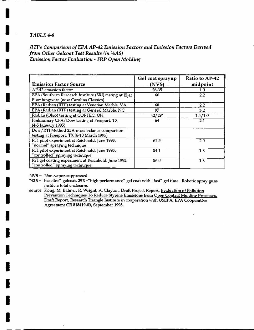
presented as Tables 4-7 and 4-8 in this document Based on their
evaluation, RTI concluded that the EPA AP-42 emission factors at FRP
manufacturing facilities were approximately two times higher than the
current FRP open molding spray layup AP-42 emission factors.
Evaluation of the RTI-referenced emission studies indicates that
insufficient information was available in these studies to accurately
estimate emission factors. The information that RTI was required to
assume to formulate emission factors for these facilities (i.e., styrene
ERM-NORTHEAST 4-9 1 C89W16.7471lcRm

I ,I I I I I I I I I I I I I I I I I I
CONFIDENTIAL WORKING DRAFT
content, hours of operation, stack emissions, collection efficiency, raw
materials usage) is very sensitive to change and can result in large
variations in the emission factors estimated.
The resin spray layup emission factor determined by RTI for the GEA
Dynamic facility was based on emission measurements collected from
grab samples and included emissions from gelcoat spray layup and
filament winding operations. Due to the use of non-continuous emission
measurement methods and inclusion of emissions and materials usage
from non-resin sprayup operations, the accuracy of this emission factor is
suspect.
In addition, to formulate the gelcoat spray layup emission factor for the
General Marble facility, RTI had to assume the styrene content of the
gelcoat, the number of hours during which gelcoating occurred, the
cumulative stack emissions and the capture efficiency of the exhaust
stacks tested. Although Radian had collected emission measurements
from the gelcoat spray booth stack and the gelcoat drying oven inlet and
outlet stacks, RTI included only the spray booth stack and drying oven
outlet stack emissions in their emission factor determination. Correcting
RTI’s calculation to include gelcoat spraying and drying emissions from
all three stacks, results in an emission factor of 111%.
Obviously, there is something wrong with this estimation since the
amount of styrene emitted cannot be greater than the amount of styrene
available. Possible problems with this emission fador estimation include:
(1) overestimation of the gelcoating hours of operation; (2) collection of
styrene emissions from nearby non-gelcoat sources, such as resin pouring;
(3) underestimation of gelcoat raw material usage; (4) inaccurate emission
measurement; (5) non-concurrent stack emission measurements; and/or
(6) underestimation of the styrene content Based on the unattainable
gelcoat spray layup emission factor determined for this facility and the
ERM-NORTHEAST 4-10 1089001 6.747ncnrn

I I I I 1 I I I I I I I I I I I I I I
CONFIDENTIAL WORKING D M
potential problems associated with its estimation, the accuracy of this
emission factor is suspect Problems were also identified in the generation
of the emission factors for the Venetian Marble and Cortec facilities. All
these emission factors are qualified with an " E in the summary tables.
Due to the lack of sufficient information and the sensitivity of the
assumptions used to formulate the emission factors for these facilities, the
accuracy of the emission factors developed from studies conducted at
Venetian Marble, General Marble, Cortec and GEA Dynamic are suspect
and should not be used to evaluate the accuracy of AP-42 emission
factors.
In contrast, the development of the RTI spray layup emission factors and
the CFA hand layup emission factors were fairly well documented.
Adequate information (e.g., emission rates, raw chemical usage, styrene
content) was collected during the SA1 and CFA studies to estimate spray
layup emission factors for the product fabrication processes being tested
(i.e., spray layup of resin and gelcoat onto a laboratory box mold) and
hand layup processes being tested (i.e., hand layup of resin in a lab). In
addition, quality control procedures were followed.
Additional Document Emission Factors
Emission studies were identified in six of the additional documents
reviewed. These are identified in the tables as: MNTAP; EPA/Radian,
HydroSports; Boat Plant A; Boat Plant 8; Boat Plant C; and Boat Plant D. The
MNTAP, Boat Plant A, B, C and D emission studies are all well documented.
Adequate information (e.g., emission rates, raw chemical usage, styrene
content) was collected during these studies to estimate emission factors
for the product fabrication processes being tested (i.e., resin spray layup
bench-scale tests, resin and gelcoat spray layup at boat building plants
and resin and gelcoat lab-scale spray layup).
ERM-NORTHEAST 4-11 1089w16.747/lcnm
I I I I I I I I 1 I I I 1 I I I I I 1
4.2.2
CONFIDENTIAL WORKING DRAFT
The document containing the Hydro-Sports emission study, Volatile
Organic Compound Control at Spec+ Sources in Louisville, KY and Nashville,
TN, contains an overview of this study and a summary of emissions
information. Sufficient information is not provided in this document to
verify the summary information provided. Emission factors from this
study are therefore considered to be estimated.
Scale And Size Of Tlte Process Being Tested
Emissions studies demonstrate that lab and bench-scale studies as well as
emission studies for small scale FRP fabrication processes are not
representative of boat building FRP processes. Due to variable FRP
fabrication process parameters (e.g., higher percentage of overspray,
thinner laminate thickness, smaller mold size, different mold shapes, etc.),
lab and bench-scale studies and studies for fabrication of small products
overestimate emission factors for large scale FRP open molding processes.
As shown in Tables 4-2 and 4-5, numerous emission factors are derived
from lab and bench-scale tests. As shown in Table 4-5, emission factors
from these small-scale tests are generally higher than emission factors
derived from full-scale tests and are always higher than emission factors
derived from full-scale boat building tests. Emission factors for smaller
products (e.g., bathroom products, counters panels, small boat parts) and
for flat and/or convex surfaces (i.e., molded sinks, counters, panels, box
molds) are also generally higher than those for boats.
Higher emission factors for lab and bench-scale studies and small FRP
product molding are probably due to the higher percentage of overspray
experienced during these studies and the thinner laminate thickness
needed for these products. Because emission factors are higher for
oversprayed materials than applied laminate, a process experiencing high
~~~
ERM-NORTHEAST 4-12 I 0890016.747ilcnm
I I I I I 1 I I I 1 I I I I I I I I 1
4.2.3
CONFIDENTIAL WORKING D b U T
overspray will have a higher emission factor than a process using the
same amount of material with less overspray. Small, convex and/or flat
molds have considerably higher overspray than large concave molds. In
addition, studies clearly demonstrate that FRP fabrication emissions
decrease with increased laminate thickness (CFA, 1995). Additional
discussion regarding laminate thickness is presented in Section 4.2.4.
Product Being Fabricated and the F R P Fabrication Process
Although the open molding processes for the various FRP products
manufactured are similar, process emissions may vary considerably
depending upon the sequence of processing and the curing techniques.
EPA and RTI emission factors for full-scale gelcoat spray layup were derived
from either synthetic marble bathroom product fabrication processes or panel
fabrication. Some bathroom products were gelcoated after molding and all
gelcoated bathroom products and panels were cured in an oven. At boat
building facilities, the mold is gelcoated prior to any resin application and the
gelcoated molds are never? heat cured. Increase emissions with increased
temperature has been clearly documented in numerous studies.
The E F A 4 resin spray layup emission factor was derived from a fullscale
tank coating process. This process, which entails application of resin to the
outside, convex surface of a tank, is not repmntative of the boat building
process. The EPA discussion document resin spray layup emission factor
was derived from an emission test conducted at GEA Dynamic facility, a
counter, panel and pipe fabricator. Although this test was used in the RTI
report to evaluate resin application emissions, this emissions from this test
also included emissions from gelcoat spray layup and filament winding
operations. Not only is this test not representative of boat fabrication, it is
also not representative of resin spray layup for panel fabrication.
ERM-NORTHEAST 4-13 1089W16.747/lchm

I I I I 1 I 1 I I I I I I I I I I I I
4.2.4
CONFIDENTIAL WORKMG DRAFT
As shown on Table 4-6, available full-scale emission information for hand
layup of resin and gelcoat is extremely limited. This corresponds to
limited use of hand layup in the FRP open molding fabrication industry.
Other Factors Affecting Emissions
Identification of the other parameters affecting emissions for the source
documents is provided in Table 43. Although these factors affect emissions,
sufficient information is not available for all parameters to make qualitative
comparisons between the various FRP fabrication products.
The following additional factors are discussed below:
. .
raw materials (styrene content, catalyst); hand rohng time; applicator and application technique; air flow; emission measurement technique and procedures; laminate thickness; curing time and gel time; and temperature and humidity.
Raw Materials
Six of the referenced emission studies (Ashland, Kingston Polytechnic, U S Chemicals, CFA, RTI and h4NTAP) evaluated changes in raw materials to
accomplish emissions d u c t i o n Testing conducted in these studies;all l a b
scale, demonstrated that use of low VOC resins and gelcoats, vapor
suppressed resins and low styrene emission resins reduce spray and hand
layup emission and emission factors. In addition, the h4NTAP and RTI
studies also demonstrated that use of BPO catalyzed resins reduces emission
factors; however, the percent reduction from this change varied widely
between the two tests.
ERMNORTHEAST 4-14 108wOI 6.747flcnm
I I 1 I 1 I I I 1 1 I I I I 1 I I I 1
Hand Rolling . Time
CONFIDENTIAL WORKING DRAFT
The Kingston Polytechnic Study, referenced in the SAI document, evaluated
the effects of rolling time on hand layup emissions. According to this study
[SAI, 19821, emissions increase with increased rolling time. According to the
Boat study, rolling accounts for 1% of total emissions from =in application
[EPA, 1-01.
Application Technique
The majority of studies used chopper guns for resin application; the Cortec
panel fabrication plant used automated HVLP spray guns. During the RTI
lab tests, AAA and HVLP spray guns were tested. The type of spray gun had
little effect on emissions for gelcoat and =in application; however,
controlled operator (i.e., careful) spraying reduced gelcoat and resin spray
layup emissions by 24% and 35%, respectively. In addition, the RTI study
also demonstrated a considerable decrease in resin hand layup emissions
(52%) with the use of flow coaters and pressure fed rollers.
Air Flow
Although the Kingston Polytechnic study concluded that emissions increased
with wind speed, the CFA study and the RTI studies concluded that the
effect of air flow on hand and spray layup emissions was insigdicant
Consequently, although air flow rates at boat plants are higher than those at
other FRP open molding fabrication plants, emission factors are not expected
to be higher at these high air flow facilities.
Emission Measurement Technique And Location
Due to the non-continuous nature of many operator-dependent fabrication
processes, emission spikes are expected throughout the fabrication process.
ERM-NORTHEAST 4-15 10890015.747ll~m

I I I I I I I I I 1 I I I I I I I I I
CONFIDENTIAL WORKING DRAFT
Consequently, emission measurement techniques that characterize emissions
throughout the entire fabrication process must be used. Three types of
emission measurement techniques were used in the referenced air emission
studies: mass balance, vapor sample collection and analysis, and real-time
emission measurement Since vapor sample collection results in a grab
sample result, these onetime results are often correlated with real-time
emission estimates to obtain long-term emission measurements. RTI, which
estimated emission factors using both mass balance and real-time emission
measurement techniques, found that the results obtained via these techniques
were in good agreement
Emission measurements in the GEA Dynamic study were determined via
grab charcoal tube samples without real-time measurement correlation.
Consequently, the emission factors developed for this study are suspect
Emission measurements at Boat Plants A and B were also determined via
charcoal tube grab samples. However, multiple short-term (2-hour) and long-
term (eight and nine-hour) samples were collected to evaluate emissions over
the process cycle. Using the short-term results, average process vapor
concentrations were determined. The higher of the short-term average value
and the long-term value was then selected and used to estimate emissions at
each of these facilities.
Laminate Thidcness
The CFA study demonstrated that laminate thickness has a significant effect
on emissions. Increasing the laminate thickness from 0.041 inches to 0.088
inches decreased emission factors approximately 31%. As discussed in
Section 4.22, since the laminate thickness for boats is considerably thicker
than the thickness for smaller FRP products, the emission factor for boat
fabrication are expected to be lower.
ERM-NORTHEAST 4-16 1089001 6.747flCNn

I I I I 1 I 1 1 I I I I 1. I I I I I
CONFIDENTIAL WORKING DRAFT
Both the Radian Cortec and CFA studies observed emissions and emission
factor decreases with faster gel time; and the RTI study observed a decrease
in emissions with cure time.
Temperature
As with any evaporative loss, emissions from FRP processes increase with
temperature; an increase in emissions was observed by Kingston Polytechnic
in their study. Consequently, emission studies with heated curing would be
higher than those with ambient temperature curing. Heated curing was
conducted in at least two of the referenced studies (SA1 Plant C and General
Marble).
ERM-NORTHEAST 4-17 1089001 6.747Achm I
I I I I I I I I I I I I I I I I I I I
TABLES
1 I I 1 I 1 1 I I 1 I I I I
i b
I I 1 1 I 1 I I I
3
I
i
C

m


1
$
3
I-
o'
E m rn
Y
0

I I I I I I 1 I I 1 I I I I
!
i
P i I ! ! i
! : I ! j i I
!
I I I I I I I I I I I I
L I
i I !
L I
i i
I I
1
< a h N
d

I I I I I I I I I I I I
L I
i : j :
I. I
i i
: i

I I I I I I I I I I I
L 1
i i i I
L I
i i
1 I
!


I I I I I I I I I
I. 0)
0 5
- 3 m 0 9
.", l
I
-
I I I 1 I I I I I I I I I I I I I I I
RP Jtrdusty Reference Product Styrene Content Application
Resin & Gel Catalyst Techniques
typically fiberglass 43% resin hpically
AP-42 .& References products 35% gel hlEKP SA1 Report
~ -. . . .- - __- -. . . . , . bath products, 40.53% resin containers 3842% gel See AS for more detailed information
NP SL'/SLarMC . . . - .. . . - . BAAQMD'
Ashland Chemical - . - . . ~~
HL/HL .. ~ .
Shasta County lab NP NP . . . - - .--
. . .. . .
NA
NP . . -- ..
. - . ~ .
chopper gun NP . . . . _ .~ ~ .
NA NA .- ...
~. ~ ~
curved . _ _ - .
..
flat, I-D? ~- -. . . .
. . .
NP I t ~~ - - - NP
.. .. .- - -
gravimetric NP . . . ~
..
. .~ . gel 66
resin: 50 ~. . .
- ~~~
, - .. - . ..
I
! NP NP I . .. .
Table 4-4 Emission Factor Evaluation Comparison of RFP Open Molding Parameters
GeVaesirr
Page I of 3 CONFIDENTIAL
DRAFI'
bAS Emissiotrs
I I I Other Parameten That May Effect Emission Factorr
I
Eniissiorr Measurement
Emission Lantirtote Measurement
Location Thickness Rolling Time Applicator Distance i-t EF inc ~ / R T I I I EF inc ~ . / A F I I
NP -. I NP . I - ,, I pray bwth exhaust __ ~ ~
NP
NP
NP
I .- - .
after each coat I I - . . .
NP -. ..
- . . . . . . ..
NP . .
shed exhaust - - -. .
gel spray booth NA I
! - various work
stations I NP w e d . concave NP charcoal tube
I I
cannot be calc EFs; no
1 NP/SL NA 44% resin
odem Plastin lab, boats 36%L!?E resin I I
l ab gravimetric boats: c h d
worker exposure
worker exposure areas; exhausts
cannot be calc EFs; no
AshlandChemical lab I 45% resin flat, 1-D gravimehic * S may be low due
?plants NP Pacific hvimnmental lgenerd FRP
NP NP I I 1 I I l!h%. Slmm Memo References I
PA/SRI Eljer Ibath products?. document not avai
I 4 - t mncave 0.07dm~3Isec * SL/MC synth marble bath
EPA/Radiw Venetian products NP
synth marble bath EPA/Radian, General products NP
NA - only gel
gel 45% spray, 55% cure??
spray booth
gel spray booth, gel cure oveq r s i n cure oveq mixing
very low
T 0.7-6
w e d , I I Tedlar bag w/ concave d s d / s e c GC/FID
moderate, good dust collection
rn 8-10 min
faster GT automated
HLW I NP gel 32% spray,
@ % c u r e , Radian/I7, C o r k panels NP
Bison, GEA Dynamic panels 3545% resin
NM
NP NP/SL NA NP NP three outlet stack; NP NM I
r' ~
I I I I I I I I I I I I I I I I I I I
_ -. - rb - box mold - -
- . - - . . , - . 38.7%reg [iso]
25.4%lv[iso/npg] MEKP __ - -. . .
EF dec 3%
38%lp [dcpd] 35%lv [dcpd]
43.5%VS[ortho] 43.3%VSw[ortho ] 42.6% [dcpd]
..__
- ench-scale test; ldlity produces variety of d U C t . 5
application: controlled SL red E 35%; modified HL red E 52% from SL; modified HL consum
resin onlv .46%[0rtho] MEW 44% [ortho] B p o
38%LSE[o/d] MEKP Gladraf t 33% 1162 [o/d] MEW - /SL NA LPA Series NP ____
SL/HLhulls & SLsmaU parts
SL/SL
SL/SL
SL/SL
NP NP NP
NP NP NP
NP NP NP
NP NP NP
NP
104,034 dscfm 20-69.000 '
dscfm
5500-7400 cfm
NP charcoal tube
(€PA 18) charcoal tube
(EPA 18)
charcoal hbe (EPA 18); PID; good correlation
Table 4-4 Ellzission Factor Evaluation Colnpai~ison of RFP Open Molding Parameters -
Page 2 o f3 CONFIDENTIAL
DRAlT
V Other Parameters That Mar Effect Einissiou F' Yand L a p ,
lollirig Tim
spr' , ,,
Emission Measirreiirerit
Locatiori
GeVResiri Applica tioii Tecltrtiques
Eir~issiorr Measurement
'aAS Enrissions - Appl ic t iod
Curing Styrene Corrtent
tsco Balhware quaGIass
Applicability to Boat Manufacturirq
Ambient Temp/RH
Particulate Emissiorrs Applicator Distance Surface -
ath producl9 - document not available ath ~ r o d u c l s ~ . documenl not avnilablc -
sign EF (31 %) w,
t h i c h -
NP
NP .
-
mod. EF dec (18%) w/
faster GT
I I
NP
73F/58%
..
, see above
I
I I i I --__ 6+-1/<40%
minor de, in
THC/FID/grav
stack venting process chambe NP NA Np
-flat, convex mold
__
..
flat, convex mold
.. .-.
NP - /HL 'ly below n
NA
. .
NP
- .
32-50% spray; ~- ~
boat molds are not flat - !I coat test parameter
. - SL gravimetric & FII 1 .... exhausts .... . CT: 17-30
. . 5 W % curing
.. _. Edec24%
w/conholled SL; less mat'l
usage -
measurement insip effect techniques in goo
on s agreement -, . .- .- ~ .
see above .. .... . -~
insign effect on 5
insign effect on E - ~
E decrease with Cl :I coat test results
... . ~. . ._ - - .
MEKP M E W MEKP MEKP
B P O - .
modified H L :flow coater & pressure fed roller) & SL
3843% spray; 3742% curing __~__
AAA spray gun sin test parameters
. . . _ _ ib - box mold - CT: 17-30
see above
see above . .. boat molds are not flat
~~ .. . . .. . . .
sin test results (formulation: Iv resin red E 36%; %resin red E k; BPO catalyst red E 3%
I less mat'ls I - ther References -
flat before and aftei
curing 69-76% spray; 2431% curinz
o p e n a p static; NP gravimehic -__ NP NM NTAP
NTAP results I I I eneral FRP - no emissions information
enerd FRP - no emissions information >A R R R . I
1,
I ' Tin€
!
'A/Radian, Styrene.. I I - 1
10% overspray loss; some os polymerizes;
I% of styrene lost before
Nolymeriratic n complete
.einforce matls: 0.8
0.80" -
NP
emissions information not applicable since AP42
derived
mostly M E K p & BOP
NP
NP
1% styrene loss from AP-42 values + inc spray gun
NP Bat Study NA
NP
NP
NP
-
hulls. concave, curved
concave, curved
concave, curved
- - - concave, curved -
pmcess is directly applicable; however,
insufficient information tc definitively calculate the
emission factors
I j NP 'A/Radia Hydr- torts
ant A
ant B
NP NP
NP - NP
NP ' 81F/
I 79F/
oats (18'22') 34% gel exhaust
exhaust
NM
NM
NP
NP
directly applicable
dirrctlv aor,licable NP
NP
oats (22'-30') 30.4% gel
40% resin 35% gel
NP
NP i NP NP - exhaust NM antC NP directly applicable
I C\ ... \NMMA\TBL-44.XE
5 / z / 96
I/-
I I I I I I I I I I I I I 1 1 I I I 'I
1
I Hand Layup Sprayup Other Parameters Tltat May E//ect Emission Facton I
CeVResin E~nissioa Emission I %AS Enrissioris Measuremerit Lamirlate Curitgg/Gei Anibierit Particulate ~ ApplictiorJ Applicability to Boat Sfyretie Coniterit Appiica tion Measuremerit Mniiufncturirig
FRP 1 1 t d ~ s t y Reference Product Resin b Gel Catalyst Teclrniques Rolling Timc Applicator Distance Surface Air Fiom Techiriqiie LOCRtion Thickness Time, nzin ?'enpnrp/RH Biiissions curiiig ~~ ~~ --------
- .. -- . . __.-. ~~~ ~
Plant D resin rv/chop lab, flat boards 30.50% resin MEKP -/SL NP resin \*/woven roving lab, flat boards 3&0% resin MEKP -/HL NP NP NP flat, i -D NP gravimetric NA NP 120 min 75F NM NP applicable
. __ . . . . . . .- . .. ._ . - . . -. .~ NP flat, I-D NP gravimetric NA NP 120 min 75F NM NP lab testing. not directly
1Z6fls &aids- 30% gelcoaT ----MW---TL/: NP NP t?p- gravimetric N A 60- 1 - 7 5 ~ NM' flat, NB --
.- . -. - __ -- . . . ~ , . - . ~ ~ ~ - NP ~- - - ~ . . . ~~
N P ' . -~ ~~p-- ___ . . ~ -- ~ - - ' ~ ~~ '- ~ ' gelcoat . - -
I Notes: - (1) Unless otherwise noted, resins were non-vapor suppressed (NVS). (2) Estimated total plant exhaust flow rote. Range spans from small plants producing small boats (i.e., <30 f t ) to large plants producing large boats (i.e., >30 ft)
EF determined during study adopted as the AP42 EF.
S: styrene emissions EF styrene emission factors SL spray layup H L hand layup
M C marble casting. not a boat mfg process I S E low styrene emission resin NP: information not provided N A not applicable conv: conventional
Ip: low-profile resin I": low-voc VS: vapor/styrene suppressed
T temperature VSw: vapor/styrene suppressed + wax
[ 1: base for gel or resin, if available WS! wind speed a -e time [o/d]: ortho/dcpd mixed resin base RT'rolling time a gel time HVLP: high volume low pressure spray gun
AAA air-assisted airless spray gun
AF'air flow 1
C\ ... \NMMA\TBL_44.XIS 5/22/96

TABLE 4-5 FRP Open Molding Emission Factor Evaluation Detailed Product Line Emission Factors
I
I
CONFIDENTIAL WORKING DRAFT
Manufacturing Processes Tested
showers, tubs, sinks & panels boats synthetic marble counters, other lab
sills
Resin Hand Iavuo: N - 4 2 EF: 5-10
I I I I I I I I
1
i
1 TABLE 4-5 (con't)
I FRI' Open Molding Emission Factor Evaluation Detailed Product Line Emission Factors
-
I I
CONFIDENTIAL WORKING DRAFT
I I I I I Gelcoat Hand Iayup; AP-42 EF: 26-35
Rp.nge 26-35 P" 47 P.
Shasta County 47 P. AP42 References
Aristech to EPA 26-35 PA
Non Vapor Suppressed I II I Manufacturing Processes Tested I
I 1 I
II
Manufacturing Processes Tested
showers, tubs, sinks & panels boats synthetic marble counters, other lab
sills
Resin Spray Layup; AP-42 EF: 3-9 Range 9.5-10.3 EF'A Discussion Document R n 9.5-10.3
I I I
AP42 References I
- boats I syntheticmarble 1 counters, I other I lab II
I
showers, tubs, sinks & sills I II
esin Hand Layup; AP42 EF: 2-7 I L e I I 1 I I 235-6.3
I I I I I 2.35 11 Notes:
I- Values greater than the M-42 emission factor are presented in bold. Emission factors presented as percent of available styrene. Unless otherwise identified, estimated emission factors were not considered for the range value. E: estimated EF; insuffiaent information provided to accurately determine EF; information (e.& styrene
content, hours of operation) assumed and/or emission from various FRF' processes were combined. I I P: EF provided; however, sufficient information was not provided to verify the EF.
a: method of measurement not provided. nb: no testing provided to substantiate emission factor; as per Aristech's comment letter, range was assumed
to be equal to spray layup I I 2
I I I I I I I I I I I I I
l i 7 0

I I I I I I I I I I I I I
W
3
. .
s '2 .- In In
aJ e!
3 a 2
2
0 u
N

. -
~~ ~
AP42 emission factor EPA/Southern Research Institute (SRI) testing at Eljer Plumbingware (now Carolina Classics
comparison testing at Freeport, TX Dow/RTl Method 25A-mass balance
I I I I I I I I 1 I I I I I I I I I I
SP'aYuP AP-42 sprayup AP42 (VS) midpoint (NVS) midpoint 3 - 9 1.0 9 - 1 3 1.0 16 2.7 NA NA
NA NA ' 24 2.2
TABLE 4-7 RTI's Comparison of EPA AP-42 Emission Factors and Emission Factors Derived from Otlm Resin Test Results (in %AS) Emission Factor Evaluation - FRP Open Molding
Bison Engineehn testinn at GEA NA I NA 24
Emission Factor Source
2.2 Dynamic-FabricaIbrs, ID- RTl resin experiment at Reichold, June-July 1995, run RIO (NVS resin with "normal" spraying technique) RTI resin experiment at Reichhold, June-July 1995, with "controlled" spraying technique
NA NA 27.1 2.5
10.6 1.8 17.5 1.6
I I I I I I I I I I I I I I I I I I I
Emission Factor Source AP-42 emission factor EPA/Southern Research Institute (SRI) testing at Eljer Plumbinpare (now Carolina Classics) EPA/Radian (RTP) testing at Venetian Marble, VA EPA/Radian (RTP) testing at General Marble, NC Radian (Ohio) testing at CORTEC, OH Preliminary CFA/Dow testing at Freeport, TX ( 4 5 January 1995) Dow/RTI Method 25A-mass balance comparison
TABLE 4-8
. -
(NVS) midpoint 26-35 1.0 66 2.2
68 2.2 97 3.2
42/29’ 1.4/1.0 64 2.1
RTI’s Comparison of EPA AP-42 Emission Factors and Emission Factors Derived from Otlrer Gelcoat Test Results (in %AS) Emission Factor Evaluation - F R P Open Molding
. _ “normal“ spraying technique
“controlled spraying technique
“controlled spraying technique
RTI pilot experiment at Reichhold, June 1995,
RTI gel coating experiment at Reichhold, June 1995,
I Gel coat sprayup I Ratio to AP-42
54.1 1.8
56.0 1.8
I1 RTI d o t exDeriment at Reichhold. lun~
N V S = Non-vaporsuppressed. *a%= baseline” gelcoat, 29%=“high performance” gel coat with “fast” gel time. Robotic spray guns
inside a total enclosure. source: Kong, M. Bahner, R. Wright, A. Clayton, Draft Project Report, Evaluation of Pollution
Prevention Techniyues To Reduce Stvrene Emissions from Open Contact Moldinp. Processes, Draft Report, Research Triangle Institute in cooperation with USEPA, EPA Cooperative Agreement CR 81841943, September 1995.
~ -
CONFIDENTIAL WORKING DRAFT
5.0 CONCLUSIONS AND RECOMMENDATIONS I I
I I I I I I I I I I I I I I I
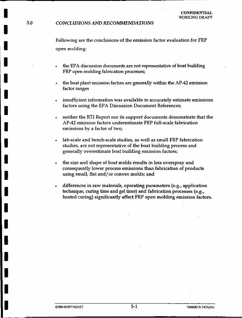
Following are the conclusions of the emission factor evaluation for FRP
open molding:
.
.
.
the EPA discussion documents are not representative of boat building FRP open molding fabrication processes;
the boat plant emission factors are generally within the AP-42 emission factor ranges
insufficient information was available to accurately estimate emissions factors~using the EPA Discussion Document References;
neither the RTI Report nor its support documents demonstrate that the AP-42 emission factors underestimate FRP full-scale fabrication emissions by a factor of two;
lab-scale and bench-scale studies, as well as small FRP fabrication studies, are not representative of the boat building process and generally overestimate boat building emission factors;
the size and shape of boat molds results in less overspray and consequently lower process emissions than fabrication of produds using small, flat and/or convex molds; and
differences in raw materials, operating parameters (e.g., application technique, curing time and gel time) and fabrication processes (e.g., heated curing) significantly affect FRP open molding emission factors.
ERM-NORTHEAST 5-1 1089001 6.747Acnrn

CONFIDENTIAL WORKING DRAFT
APPENDIXA:
Bibliogmply
I I I
I I I I I I I I I I I I I I I I I I I
CONFIDENTIAL WORKING DRAFJ?
BIBLIOGRAPHY
EPA AP-42 References
Al .
A2.
A3.
A4.
A5.
A6.
A7.
A8.
A9.
M. B. Rogozen, Control Techniquesfor Organic Gas Emissionsfrom Fiberglass Impregnation and Fabrication Processes, ARB/R-82/165, prepared by Science Applications, Inc. for the California Air Resources Board, Sacramento, CA (NTIS PB82-251109), June 1982. {SAI)
Modern Plastics Encyclopedia, 1986-1987,63 (lOA), October 1986. [Modem Plastics I]
C. A. Brighton, G. Pritchard and G.A. Skinner, Styrene Polymers: Technology and Environmental Aspects, Applied Science Publishers, Ltd., London, 1979. {Applied Science]
M. Elsherif, Staff Report, Proposed Rule 1 1 62 - Polyester Resin Operations, South Coast Air Quality Management District, Rule Developments Division, El Monte, CA, 23 January 1987. [SCAQMD Rule 1162)
M. S. Crandall, Extent of Exposure to Styrene in the Reinforced Plastic Boat Making Industry, Publication No. 82-110, National Institute for Occupational Safety and Health, Cincinnati, OH, March 1982. [NIOSH)
Written communication from R.C. Lepple, Aristech Chemical Corporation, Polyester Unit, Linden, NJ, to A. A. MacQueen, U.S. Environmental Protection Agency, Research Triangle Park, NC, 17 September 1987. [Aristech to EPA)
L. Walewski and S. Stockton, ”Low-Styrene-Emission Laminating Resins Prove It in the Workplace”, Modern Plastics, 62(8):78-80, August 1985. [Modem Plastics II)
M. J. Duffy, Styrene Emissias - H a 0 Efictive Are Suppressed Polyester Resins?, Ashland Chemical Company, Dublin, OH, presented at 34th Annual Technical Conference, Reinforced Plastics/Composites Institute, The Society of the Plastics Industry, 1979. (Ashland Chemical]
G. A. LaFlam, Emission Factor Documentation fin AP-42 Section 4.12: Polyester Resin Plastics Product Fabrication, Pacific Environmental Services, Inc., Durham, NC, November 1987. [Pacific Environmental)
~ ~~~
ERM-NORTHEAST A-1 1 C890016.747AcAm

I CONFIDENTIAL WORKING DRAFT
M. Shum Memo (ll/95)References I I I I I I I I C I I I I
I I I
B1.
82.
83.
84.
85.
86.
87.
B8.
B9.
EPA/Southern Research Institute testing at Elder Plumbingware (now Carolina Classic). (EPA/SRI Elder]
EPA/Radian testing at Venetian Marble. (EPA/Radian Venetian]
EPA/Radian testing at General Marble. (EPA/Radian General]
A. Parker and J. Reinhold, Radian Corporation, Mason, Ohio, and G. Henderson, IT Corporation, Cincinnati, Ohio, Demonstration ofcapture and Control Eficiencyfor a Styrene Emission Source, Publication 94-RA111.03 presented at the 87th Annual Meeting & Exhibition of the Air & Waste Management Association, 19-24 June 1994. (Radian, Cortec]
Bison Engineering, Emission Compliance Test, Styrene and Visible Emissions: Fiberglass Reinforced Plastic Lay-up Facility, Idaho Permit to Construct 860-0035, 26 August 1993. [Bison, GEA Dynamic]
Lasco Bathware in Maopa, Nevada. [Lasco Bathware]
Aquaglass, Oregon. [AquaGIass)
Composite Fabricators Association, Open Molding Styrene Emissions Study: Overview and Summary of Hand Lay-up Emissions Study, 1995. (CFA Hand Layup]
E. Kong, M. Bahner, R. Wright, A. Clayton, Draft Project Report, Evaluation of Pollution Prevention Techniques Tu Reduce Styrene Emissionsfrom Open Contact Molding P~ocesses, Draft Report,, Research Triangle Institute in cooperation with USEPA., EPA Cooperative Agreement CR 8184 19-03, September 1995. (RTI)
Other Documents
C1. Minnesota Technical Assistance Program, Reducing Styrene Emissions in Fiber Reinjbrced Plastic Operations, March 1993. (MTAP]
USEPA Risk Reduction and Engineering Laboratory and Center for Environmental Research and Development, Guidks to Pollution Prevention, The Fiberglass-Reinjbrced and Composite Plastics Industry, October 1991, EPA/625/7-91/014. (EPA RREL]
C2.
ERM-NORTHEAST A-2 1089001 6.747Mm

I I I I I I I I I I I I I I I I I I I
c3.
c4.
c5.
C6.
c7.
C8.
c9.
c10.
c11.
(212.
CONFIDENTIAL WORKMG DRAFT
Radian Corporation, Locating and Estimating Air Emissions from Sources of Styrene, Interim Report, prepared for EPA, October 1991, EPA-450/4-91-029. (EPA/Radian, Styrene Sources)
Facsimile from John McKnight (NMMA) to Mark Elmendorf (ERM) transmitting notes and tables prepared by Mark Bahner (RTI) re: reinforced plastics, October 1995. (MB memo)
National Marine Manufacturers Association, Boat Builders MACT Tier I1 Study. (NMMA MACT Report)
Memo from Eric Noble (?) to Distribution re: using the AP-42 database for making exclusionary rule applicability determinations, 3/95. (memo re: use of emission factors)
USEPA Control Technology Center, Assessment of VOC Emissions from Fiberglass Boat Manufacturing, EPA 600/2-90-019, May 1990. (Boat Study)
Radian Corporation, Volatile Organic Compound Control at Specific Sources in Louisville, KY and Nashville, TN, prepared for EPA, December 1981, EPA-904/9-81-087, NTIS PB83-153379. (EPA/Radian, Hydro-Sporis}
ED1 Engineering & Science, Report of Source Emission Testing performed@ Four Winns, Cadillac, Michigan, at the Frisbee Street Plant, 26 April 1989, (Four Winns, Frisbee Street)
ED1 Engineering & Science, Report of Source Emission Testing performed@ Four Winns, Cadillac, Michigan, at the Cruiser Plant, 25 April 1989, (Four Winns, Cruiser Plant)
OMC Office Memo, Four Winns Air Sampling Results (3/2@8 23th Street), 21 April 1988. (Four Winns, 13th Street-3/88)
Haberlein, Robert, Ph.D., Engineering Environmental, Summary Report on the Point-ofUse Dynamic Styrene Emission Testing at the Salisbury Bayliner Facility, prepared for Don Barnhill, U.S. Marine Bayliner, 1 February 1992. (Salisbury Bayliner)
ERM-NORTHEAST A-3 1089001 6.747ncnm
I I I I I I I I I I I I I I I I I I I
CONFIDENTIAL WORKING DRAET
APPENDM B:
Emission Factor Calculations

I I I I I I I I I I I I I I I I I I I
L I: 7
ii
3
f
P 3
c E 9
81 I A F
a? Lo
v $ c 2 5
I I I I I I I I I I I I I I I I I I I
Y
.s 2 E x
&? '0
C 0
I .-
VI VI
.2 01
m
I I I I I I I I I I I I I I I I I I I
i
!.
?
!
? , i
:
, j
4 z
! E
? > c
i Y
i s

I I I I I I I I I I I I I I I I I I I

I I I I I I I I I I I I I I I I I I I

,
I I I I I I I I I I I I I I I I I I
f? n

I I I I I I I I I I I I I I I I I I I
6 5 1 h m
w m D


