Download - 4. Distributed DBMS Architecture

1
4. Distributed DBMS Architecture
Chapter 4
Distributed DBMS Architecture
2
Outline
To-Down Design of DDBMS Architecture
Schema and Distribution Transparency
Bottom-up Design of DDBMS Architecture
Architectural Alternatives for DDBMSs
Three Reference Architectures for a DDBMS
(i.e., client/server, peer-to-peer distributed DBMS,
multi-databases)
Global Directory/Dictionary
3
Introduction
Architecture defines the structure of the system components identified
functions of each component defined
interrelationships and interactions between components
defined

4
Reference Model (参考模型)
Reference Model A conceptual framework whose purpose is to divide
standardization work into manageable pieces and to
show at a general level how these pieces are related to
one another.
Three approaches to define a reference model
① Component-based– Components of the system are defined together with the
interrelationships between components
– Good for design and implementation of the system
5
Reference Model (cont.)
② Function-based– Classes of users are identified together with the functionality
that the system will provide for each class
– The objectives of the system are clearly identified. But how do
you achieve these objectives?
③ Data-based– Identify different types of data and specify the functional units
that will realize and/or use data according to these views.
– The ANSI/SPARC architecture discussed next belongs to this
category.

6
ANSI/SPARC Architecture
External View
External View
External View
Conceptual View
Internal View
ExternalSchema
Users
ConceptualSchema
InternalSchema

7
Conceptual Schema (概念模式)
RELATION EMP [ KEY = {ENO} ATTRIBUTES = { ENO : CHARACER(9) ENAME : CHARACER(15) TITLE : CHARACER(10) }]
RELATION PAY [ KEY = {TITLE} ATTRIBUTES = {
TITLE : CHARACER(10) SAL : NUMERIC(6)
}]
RELATION PROJECT [ KEY = {PNO} ATTRIBUTES = { PNO : CHARACER(7) PNAME : CHARACER(20) BUDGET : NEMERIC(7) }]
RELATION ASG [ KEY = {ENO,PNO}
ATTRIBUTES = { ENO : CHARACER(9) PNO : CHARACER(7) RESP : CHARACER(10) DUR : NUMERIC(6) }]

8
Internal Schema (内部模式)
RELATION EMP [ KEY = {ENO} ATTRIBUTES = { ENO : CHARACER(9) ENAME : CHARACER(15) TITLE : CHARACER(10) }] INTERNAL_REL EMPL [
INDEX ON E# CALL EMINX
FIEDLS = { HEADER : BYTE(1) E# : BYTE(9) ENAME : BYTE(15) TIT : BYTE(10) }]

9
External View (外部模式 ) – Example 1
CREAT VIEW BUDGET(PNAME, BUD)
AS SELECT PNAME, BUDGET
FROM PROJ
Create a BUDGET view from the PROJ relation

10
External View (外部模式 ) – Example 2
CREAT VIEW PAYROLL(ENO, ENAME, SAL)
AS SELECT EMP.ENO, EMP.ENAME, PAY.SAL FROM EMP, PAY
WHERE EMP.TITLE = PAY.TITLE
Create a Payroll view from relations EMP and PAY

11
The Top-Down Classical DDBMS Architecture
Site 1
Other sites
Site IndependentSchemas
Global Schema
Fragmentation Schema
Allocation Schema
LOCAL DB 1
Local Mapping Schema
DBMS 1
LOCAL DB 2
Local Mapping Schema
DBMS 2
Site 2
12
Global Relations, Fragments, and Physical Images
R
GlobalRelation
R33
R32
R22
R21
R12
R11
R3
R2
R1
R2
(Site2)
R1
(Site 1)
R3
(Site3)
Physical Images
Fragments

13
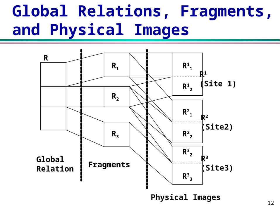
DDBMS Schemas Global Schema: a set of global relations as if database were
not distributed at all
Fragmentation Schema: global relation is split into “non-
overlapping” (logical) fragments. 1:n mapping from relation R
to fragments Ri.
Allocation Schema: 1:1 or 1:n (redundant) mapping from
fragments to sites. All fragments corresponding to the same
relation R at a site j constitute the physical image Rj. A copy of
a fragment is denoted by Rji.
Local Mapping Schema: a mapping from physical images to
physical objects, which are manipulated by local DBMSs.
14
Motivation for this Architecture
Separating the concept of data fragmentation from the concept of data allocation
Fragmentation transparency Location transparency Explicit control of redundancy Independence from local databases allows local
mapping transparency

15
Rules for Data Fragmentation
Completeness
All the data of the global relation must be mapped into the fragments.
Reconstruction
It must always be possible to reconstruct each global relation from its fragments.
Disjointedness
It is convenient that fragments are disjoint, so that the replication of data can be controlled explicitly at the allocation level.

16
Types of Data Fragmentation
Vertical Fragmentation•Projection on relation
(subset of attributes)•Reconstruction by join•Updates require no tuple
migrationHorizontal Fragmentation
•Selection on relation (subset of tuples)
•Reconstruction by union•Updates may require tuple
migrationMixed Fragmentation•A fragment is a Select-
Project query on relation.
17
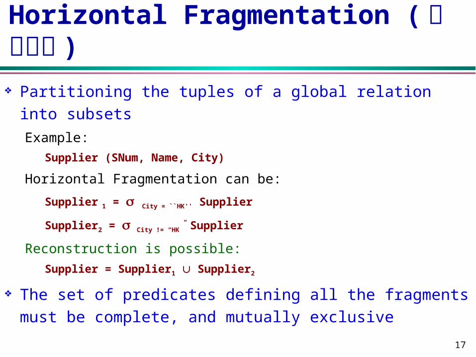
Horizontal Fragmentation ( 水平划分 )
Partitioning the tuples of a global relation into subsets
Example:
Supplier (SNum, Name, City)
Horizontal Fragmentation can be:
Supplier 1 = City = ``HK'' Supplier
Supplier2 = City != “HK” Supplier
Reconstruction is possible:
Supplier = Supplier1 Supplier2
The set of predicates defining all the fragments must
be complete, and mutually exclusive

18
Derived Horizontal Fragmentation
The horizontal fragmentation is derived from the horizontal fragmentation of another relationExample:
Supply (SNum, PNum, DeptNum, Quan)
SNum is a supplier number
Supply1 = Supply SNum=SNum Supplier1
Supply2 = Supply SNum=SNum Supplier2
The predicates defining derived horizontal fragments are:
(Supply.SNum = Supplier.SNum) and (Supplier. City = ``HK'')
(Supply.SNum = Supplier.SNum) and (Supplier. City != ``HK'')
is the semi join operation.
19
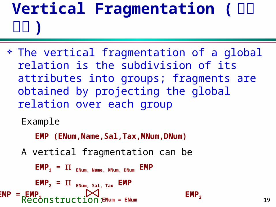
Vertical Fragmentation ( 垂直划分 )
The vertical fragmentation of a global relation is the subdivision of its attributes into groups; fragments are obtained by projecting the global relation over each group
Example
EMP (ENum,Name,Sal,Tax,MNum,DNum)
A vertical fragmentation can be
EMP1 = ENum, Name, MNum, DNum EMP
EMP2 = ENum, Sal, Tax EMP
Reconstruction: ENum = ENum
EMP = EMP1 EMP2

20
Distribution Transparency ( 分布透明 )
Different levels of distribution transparency can be provided by DDBMS for applications. A Simple Application
Supplier(SNum, Name, City)
Horizontally fragmented into: Supplier 1 = City = ``HK'' Supplier at Site1
Supplier2 = City != “HK” Supplier at Site2, Site3
Application:
Read the supplier number from the user and return the name of the supplier with that number.
21
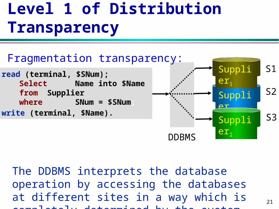
Level 1 of Distribution Transparency
Supplier2
Supplier2
Supplier1
DDBMS
read (terminal, $SNum); Select Name into $Name from Supplier where SNum = $SNum;
write (terminal, $Name). S3
S2
S1Fragmentation transparency:
The DDBMS interprets the database operation by accessing the databases at different sites in a way which is completely determined by the system.

22
Level 2 of Distribution Transparency
Location Transparency
The application is independent from changes in allocation schema, but not from changes to fragmentation schema.
Supplier2
Supplier2
Supplier1
DDBMS
read (terminal, $SNum); Select Name into $Name from Supplier1 where SNum = $SNum;
If not FOUND thenSelect Name into $Name from Supplier2 where SNum = $SNum;
write (terminal, $Name).
S3
S2
S1

23
Level 3 of Distribution Transparency
Local Mapping Transparency
The applications have to specify both the fragment names and the sites where they are located. The mapping of database operations specified in applications to those in DBMSs at sites is transparent.
Supplier2
Supplier2
Supplier1
DDBMS
read (terminal, $SNum); Select Name into $Name from S1.Supplier1 where SNum = $SNum;
If not FOUND thenSelect Name into $Name from S3.Supplier2 where SNum = $SNum;
write (terminal, $Name).
S3
S2
S1

24
Level 4 of Distribution Transparency
No Transparency read (terminal, $SNum);
$SupIMS($Snum,$Name,$Found) at S1; If not FOUND then
$SupCODASYL($Snum,$Name,$Found) at S3;
write (terminal, $Name).
S1
Supplier1
IMS
DDBMS
S3
Supplier2
Codasyl

25
Distribution Transparency for Updates
EMP1 = ENum,Name,Sal,TaxDNum10 (EMP) EMP2 = ENum,MNum,DNumDNum10 (EMP) EMP3 = ENum,Name,DNumDnum>10 (EMP) EMP4 = ENum,MNum,Sal,TaxDnum>10 (EMP)
EnumName Sal Tax 100 Ann 100 10
EnumMnumDnum100 20 3
EnumMnum Sal Tax 100 20 100 10
EnumName Dnum100 Ann 15
Update Dnum=15 for Employee with Enum=100
EMP1
EMP3 EMP4
EMP2
Difficult• broadcasting
updates to all copies
• migration of tuples because of change of fragment defining attributes
26
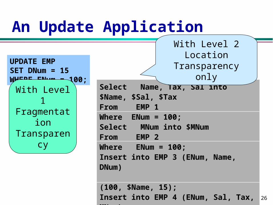
An Update Application
UPDATE EMP SET DNum = 15 WHERE ENum = 100;
Select Name, Tax, Sal into $Name, $Sal, $Tax From EMP 1 Where ENum = 100; Select MNum into $MNum From EMP 2 Where ENum = 100; Insert into EMP 3 (ENum, Name, DNum) (100, $Name, 15); Insert into EMP 4 (ENum, Sal, Tax, MNum) (100, $Sal, $Tax, $MNum); Delete EMP 1 where ENum = 100; Delete EMP 2 where ENum = 100;
With Level 1 Fragmentation Transparency
With Level 2 Location Transparency only

27
Levels of Distribution Transparency Fragmentation Transparency
Just like using global relations Location Transparency
Need to know fragmentation schema; but no need to know where fragments are located
Applications access fragments (no need to specify sites where fragments are located).
Local Mapping Transparency Need to know both fragmentation and allocation schema; no
need to know what the underlying local DBMSs are. Applications access fragments explicitly specifying where the
fragments are located. No Transparency
Need to know local DBMS query languages, and write applications using functionality provided by the Local DBMS

28
On Distribution Transparency
More distribution transparency requires appropriate DDBMS support, but makes end-application developers’ work easy.
The less distribution transparency, the more the end-application developer needs to know about fragmentation and allocation schemes, and how to maintain database consistency.
There are tough problems in query optimization and transaction management that need to be tackled (in terms of system support and implementation) before fragmentation transparency can be supported.

29
Layers of Transparency
The level of transparency is inevitably a compromise between ease of use and the difficulty and overhead cost of providing high levels of transparency
DDBMS provides fragmentation transparency and location transparency; OS provides network transparency; and DBMS provides data independence

30
Some Aspects of the Classical DDBMS Architecture
Distributed database technology is an “add-on” technology, and most users already have populated centralized DBMSs. Whereas top-down design assumes implementation of new DDBMS from scratch.
In many application environments, such as semi-structured databases, continuous/streaming multimedia data, the notion of fragment is difficult to define.

31
Bottom-up Architectural Models for DDBMS
Possible ways in which multiple databases are put together for sharing, which are characterized according to three dimensions.
Distribution
Multi-DBMS
DistributedMulti-DBMS
Autonomy
Heterogeneity
Client/server
Peer-to-peerDistributed DBMS
Federated DBMS

32
Dimension 1: Distribution ( 分布 ) Whether the components of the system are located
on the same machine or not
0 - no distribution - single site (D0)
1 - client-server - distribution of DBMS functionality (D1)
2 - full distribution - peer to peer distributed
architecture(D2)

33
Dimension 2: Heterogeneity (异质 ) Various levels (hardware, communication, operating
system) DBMS important ones (like data model, query
language, transaction management algorithms, etc.)
0 - homogeneous (H0)
1 - heterogeneous (H1)

34
Dimension 3: Autonomy ( 自治 ) Refers to the distribution of control, not of data,
indicating the degree to which individual DBMSs can operate independently.
Requirements of an autonomous system The local operations of the individual DBMSs are not
affected by their participation in the DDBS. The individual DBMS query processing and optimization
should not be affected by the execution of global queries that access multiple databases.
System consistency or operation should not be compromised when individual DBMSs join or leave the distributed database confederation.

35
Various Versions of Autonomy Design autonomy
Ability of a component DBMS to decide on issues related to its own design
Freedom for individual DBMSs to use data models and transaction management techniques they prefer
Communication autonomy Ability of a component DBMS to decide whether and how to
communication with other DBMSs Freedom for individual DBMSs to decide what information (data &
control) is to be exported Execution autonomy
Ability of a component DBMS to execute local operations in any manner it wants to.
Freedom for individual DBMSs to execute transactions submitted in any way that it wants to
36
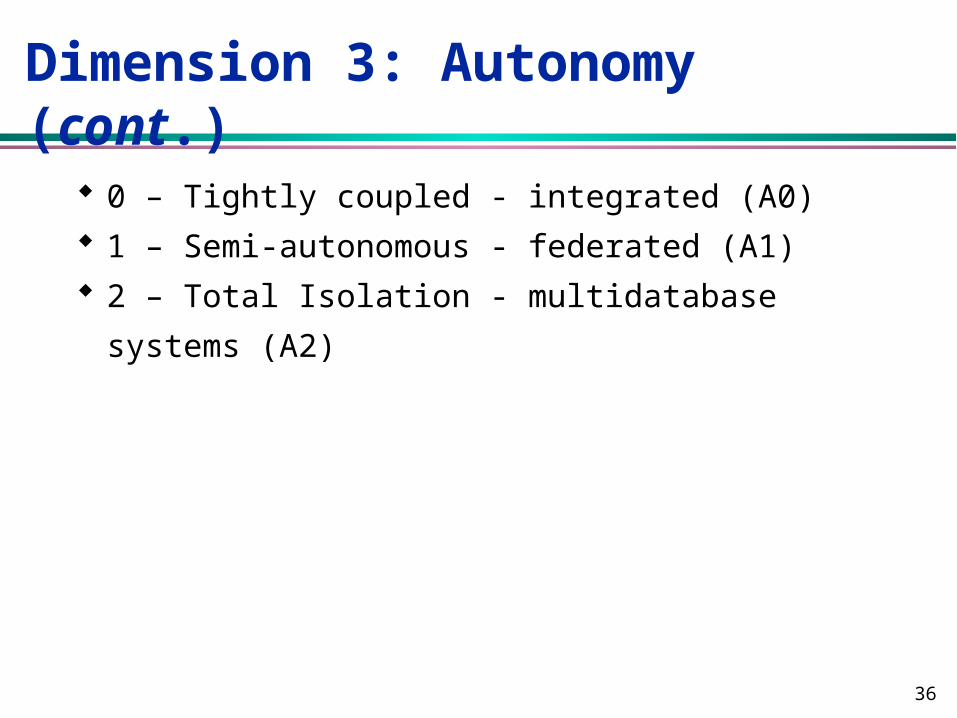
Dimension 3: Autonomy (cont.)
0 – Tightly coupled - integrated (A0)
1 – Semi-autonomous - federated (A1)
2 – Total Isolation - multidatabase systems (A2)

37
Time Sharing Access to a Central Database (Distribution)
Batchrequests
Database
DBMS Services
Application Software
Communications
response
Terminals• No data storage• Host running all software
Network

38
Multiple Clients / Single Server
High-levelrequests
Database
DBMS Services
Communications
Filtered data only LAN
Communications
Client Services
Applications
Communications
Client Services
Applications
Communications
Client Services
Applications
39
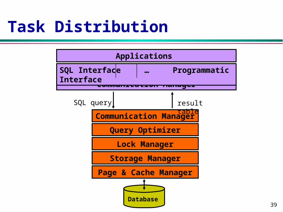
Task Distribution
SQL query
Database
Query Optimizer
Communication Manager
result table
Communication Manager
SQL Interface … Programmatic Interface
Applications
Lock Manager
Storage Manager
Page & Cache Manager
40
Advantages of Client-Server Architectures
More efficient division of labor Horizontal and vertical scaling of resources Better price/performance on client machines Ability to use familiar tools on client machines Client access to remote data (via standards) Full DBMS functionality provided to client
workstations Overall better system price/performance
41
Problems with Multiple-Clients / Single Server Architectures
Server forms bottleneck Server forms single point of failure Database scaling difficult

42
Multiple Clients / Multiple Servers
Database
DBMS Services
CommunicationsLAN
Communications
Client Services
Applications
Database
DBMS Services
Communications
• Directory• Caching• Query decomposition• Commit protocols

43
Server to Server
Database
DBMS Services
CommunicationsLAN
Communications
Client Services
Applications
Database
DBMS Services
Communications
• SQL interface• Programmatic interface• other application support environments

44
Components of Client / Server Architecture
UI Application Program
Client DBMS
Communication softwareOpe
ratin
g Sy
stem
System
Recovery Manager
Transaction Manager
Query Optimizer
Semantic Data Controller
Communication software
Ope
ratin
g Sy
stem
Runtime Support Processor
SQL Queries Result Relation
Database

45
Peer-to-Peer Component Architecture
Local
Qu
ery
Pro
cess
or
Local
Recove
ryM
an
ag
er
Ru
nti
me
Su
pp
ort
Use
r In
terf
ace
Han
dle
r
Sem
an
tic D
ata
Con
troll
er
Glo
bal
Qu
ery
Op
tim
izer
Glo
bal
Execu
tion
M
on
itor
ExternalSchema
GlobalSchema
LocalConceptual
Schema
LocalInternalSchema
GD/Dlog
USER PROCESSOR DATA PROCESSOR
46
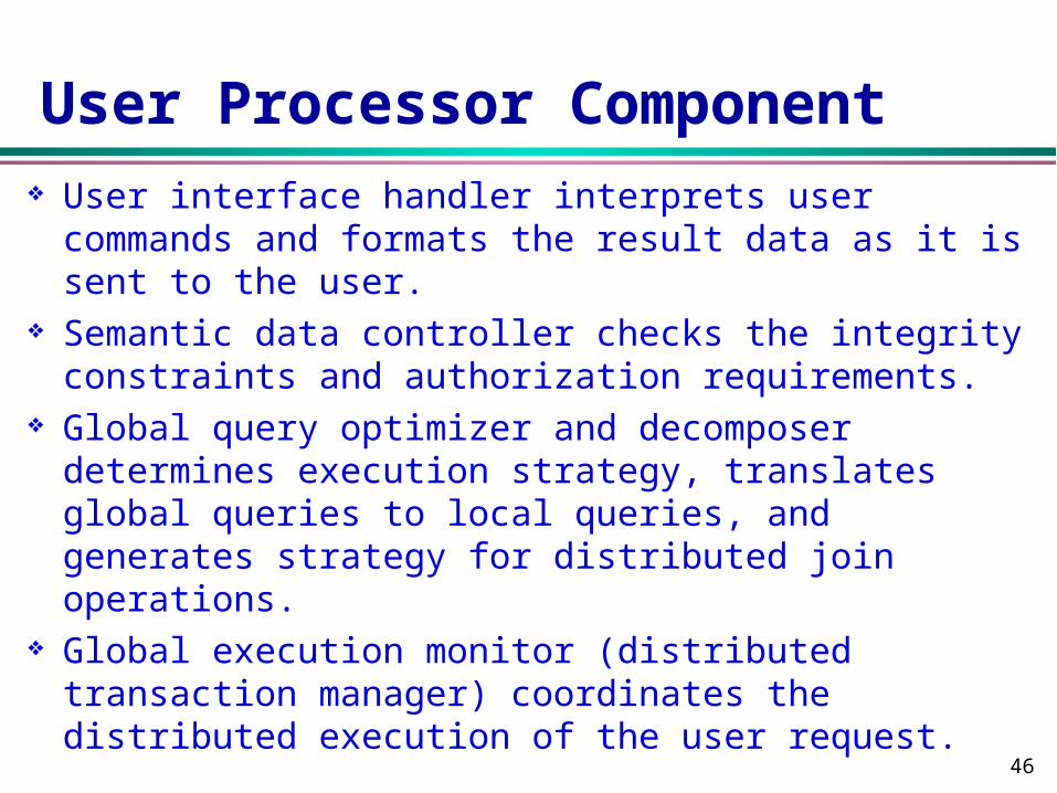
User Processor Component User interface handler interprets user commands
and formats the result data as it is sent to the user. Semantic data controller checks the integrity
constraints and authorization requirements. Global query optimizer and decomposer determines
execution strategy, translates global queries to local queries, and generates strategy for distributed join operations.
Global execution monitor (distributed transaction manager) coordinates the distributed execution of the user request.

47
Data Processor Component
Local query processor selects the access path and is involved in local query optimization and join operations.
Local recovery manager maintains local database consistency.
Run-time support processor physically accesses the database. It is the interface to the OS and contains database buffer manager.

48
Taxonomy of Distributed Databases (Autonomy)
Composite DBMSs - tight integration single image of entire database is available to any user can be single or multiple sites can be homogeneous or heterogeneous
Federated DBMSs - semiautonomous DBMSs that can operate independently, but have decided to make
some parts of their local data shareable can be single or multiple sites. they need to be modified to enable them to exchange information
Multidatabase Systems - total isolation individual systems are stand alone DBMSs, which know neither the
existence of other databases or how to communicate with them no global control over the execution of individual DBMSs. can be single or multiple sites homogeneous or heterogeneous

49
Distributed Database Reference Architecture
GCS
ES1 ES2 ESn
LCS1 LCS2 LCSn
LIS1 LIS2 LISn
External Schema
It is logically integrated. Provides for the levels of transparency
Local Internal Schema
Local Conceptual Schema
Global Conceptual Schema

50
Components of a Multi-DBMS
Multi-DBMS Layer
User RequestsSystem Responses
Runtime Sup. Processor
Recovery Manager
Scheduler
TransactionManager
Query Processor
Query Optimizer
UserInterface
Database
Runtime Sup. Processor
Recovery Manager
Scheduler
TransactionManager
Query Processor
Query Optimizer
UserInterface
Database
User
User User

51
Multi-DBMS Architecture with a Global Conceptual Schema
•The GCS is generated by integrating LES's or LCS's •The users of a local DBMS can maintain their autonomy •Design of GCS is bottom-up
GCS
ES1 ES2 ESn
LCS1 LCSn
LIS1 LISn
LES11 LES1sLESn1 LESnt

52
Multi-DBMS without Global Conceptual Schema
Local database system layer consists of several DBMSs which present to multidatabase layer part of their databases
The shared database has either local conceptual schema or external schema (Not shown in the figure)
External views on one or more LCSs. Access to multiple databases through application
programs
ES1
LCS1
LIS1
MultidatabaseLayer
Local DatabaseSystem Layer
ES2
LCS2
LIS2
ES3
LCS3
LIS3
53
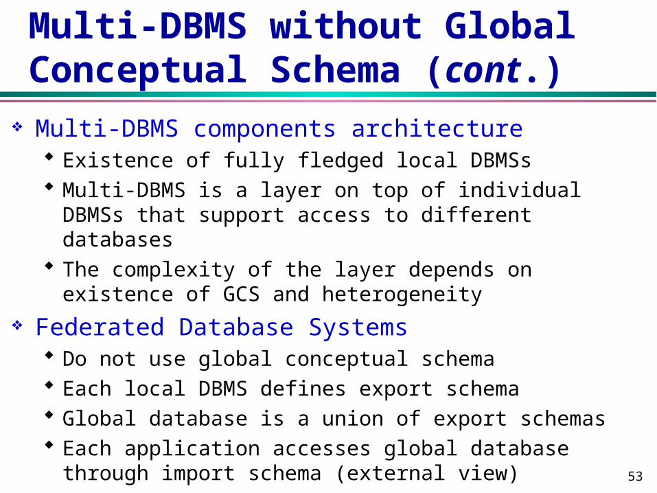
Multi-DBMS without Global Conceptual Schema (cont.)
Multi-DBMS components architecture Existence of fully fledged local DBMSs Multi-DBMS is a layer on top of individual DBMSs that
support access to different databases The complexity of the layer depends on existence of
GCS and heterogeneity
Federated Database Systems Do not use global conceptual schema Each local DBMS defines export schema Global database is a union of export schemas Each application accesses global database through
import schema (external view)

54
Global Directory/Dictionary Directory is itself a database that contains
meat-data about the actual data stored in the database. It includes the support for fragmentation transparency in the classical DDBMS architecture.
Directory can be local or distributed. Directory can be replicated and/or partitioned. Directory issues are very important for large
multi-database applications, such as digital libraries.
55
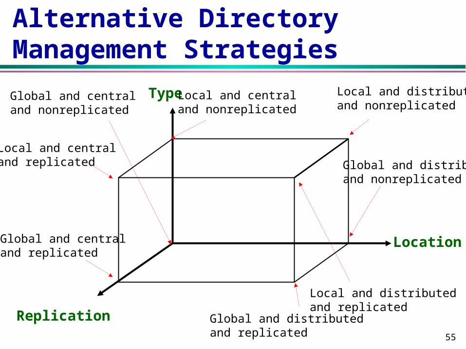
Alternative Directory Management Strategies
Type
Location
Replication
Global and centraland nonreplicated
Local and centraland replicated
Global and centraland replicated
Local and centraland nonreplicated
Local and distributedand nonreplicated
Global and distributedand nonreplicated
Local and distributedand replicated
Global and distributedand replicated
56
Question & Answer


