
Dynamic Modeling and Control of Divided Wall Column
Authors:
László SzabóSándor NémethFerenc Szeifert
ABC
A
B
C
2010.02.18
8th Meeting of Young Chemical EngineersZagreb
University of Pannonia Department of Process Engineering

2
History of divided wall column
� Dividing-Wall Column (DWC) was introduced by Richard O.Wright in 1949 : Fractionation Apparatus
� However, lack of reliable design method and concerns about the operation and control of DWC have prevented the widespread application.
� People started to pay more attention to DWC after the Energy Crisis (1980).
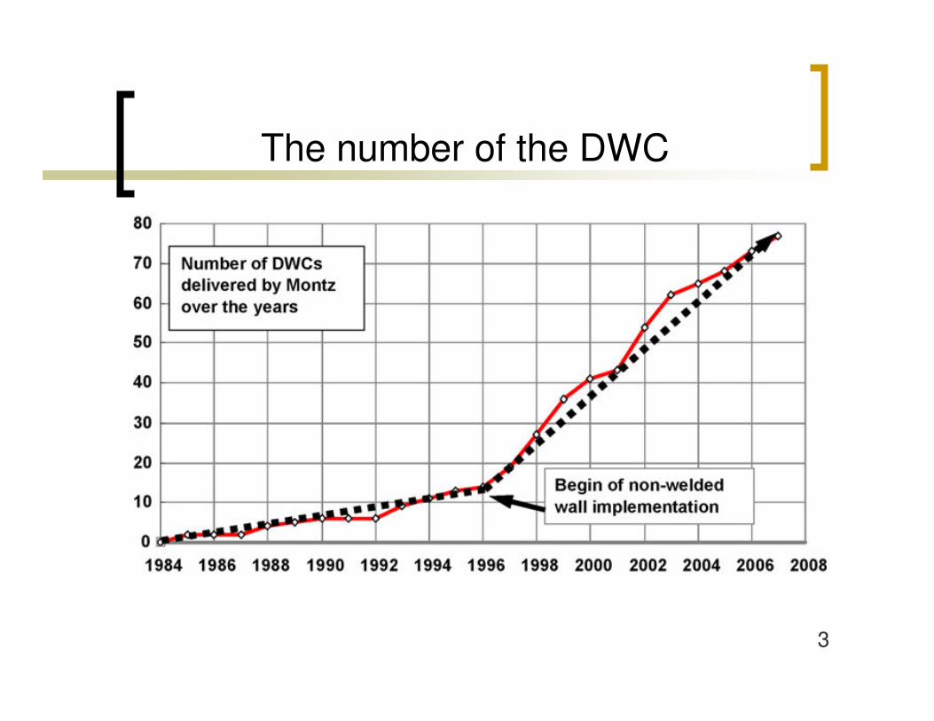
� In 1985, BASF built the first commercial DWC.� More than 100 columns installed worldwide.
3
The number of the DWC

4
The divided wall column
Bottom stream
Boil up
Side stream
Reflux
Distillate stream
Feed

5
Concentration profile of the side product
0
0,1
0,2
0,3
0,4
0,5
0,6
0,7
0,8
0,9
1
0 5 10 15 20 25
Tray
Tol
uene
mas
sfra
c (m
/m)
Feed zoneProduct zone

6
Separation task
144,4
112,1
80,1
Boiling point(°C)
0,33o-Xylene
0,33Toluene
0,33Benzene
Feed concentration(kg/kg)
Feed90 kg/h
BenzenePurity: 0,99 kg/kg
Toluene
o-XylenePurity : 0,99 kg/kg
7
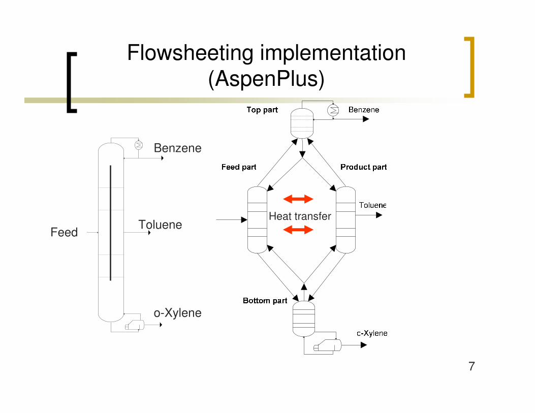
Flowsheeting implementation (AspenPlus)
Heat transferFeed
Benzene
Toluene
o-Xylene

8
Flowsheeting implementation(AspenPlus)
YesCondenser
NoReboiler
Feed
Benzene
Toluene
o-Xylene
Heat transfer
9
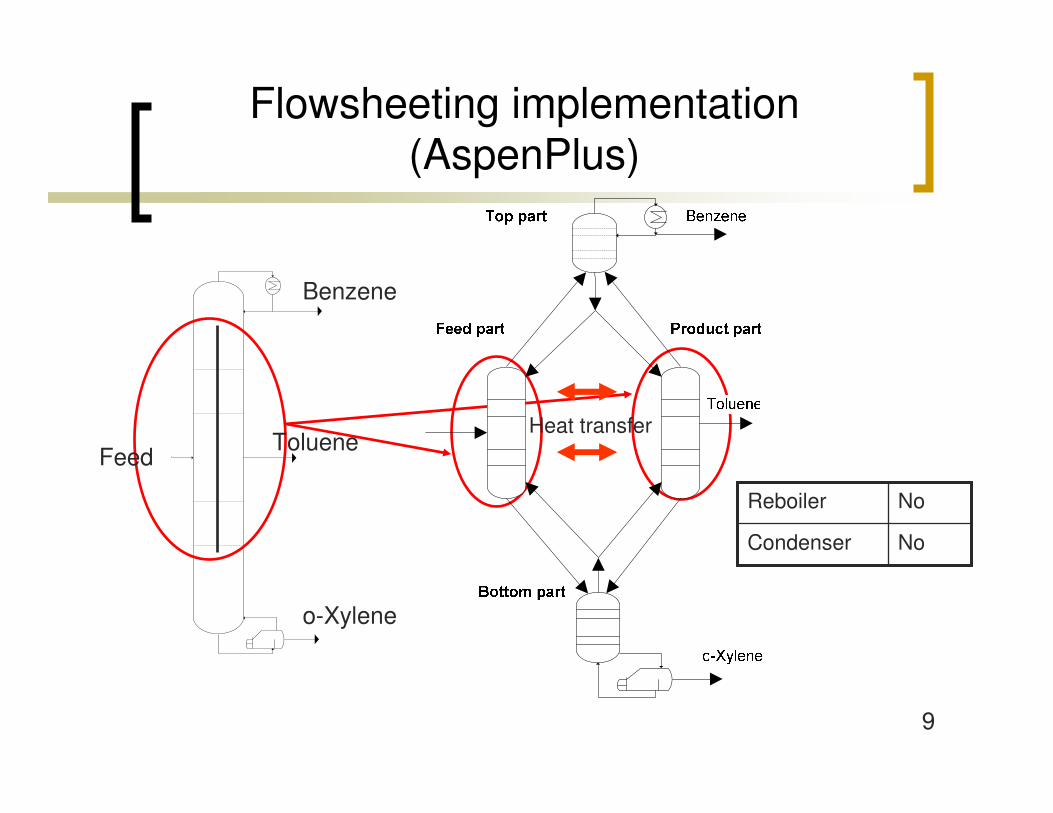
Flowsheeting implementation (AspenPlus)
NoCondenser
NoReboiler
Feed
Benzene
Toluene
o-Xylene
Heat transfer

10
Flowsheeting implementation (AspenPlus)
NoCondenser
YesReboiler
Feed
Benzene
Toluene
o-Xylene
Heat transfer
11
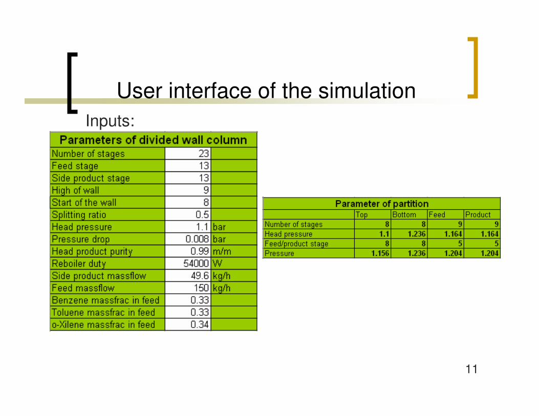
Inputs:
User interface of the simulation

12
Outputs:
User interface of the simulation
13
Parametric study
� Height of the wall� Vertical position of the wall � Splitting ratio� Comparing divided wall column to side
stream column

14
20
25
30
35
40
45
50
55
60
5 6 7 8 9 10 11 12 13
Height of the wall (tray)
Reb
oile
r dut
y (k
W)
Effect of the height of the wall
50-50%
15
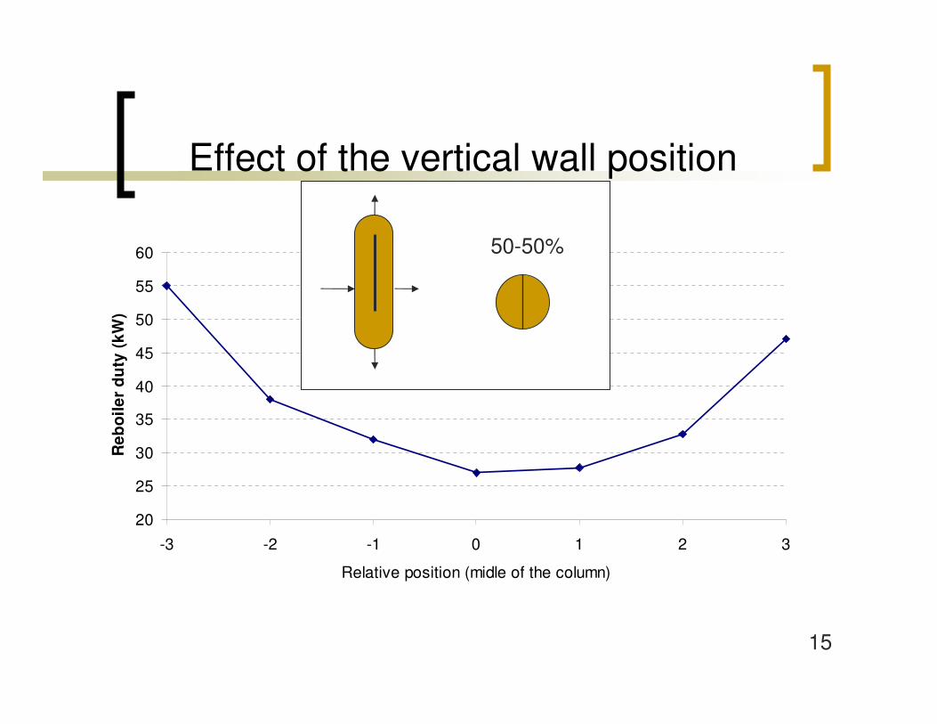
20
25
30
35
40
45
50
55
60
-3 -2 -1 0 1 2 3
Relative position (midle of the column)
Reb
oile
r du
ty (k
W)
Effect of the vertical wall position
50-50%

16
20
25
30
35
40
45
50
55
60
65
70
0 20 40 60 80 100
Splitting ratio (%)
Reb
oile
r du
ty (
kW)
Effect of splitting ratio

17
Comparing DWC to side stream column
0
100
200
300
400
500
600
700
50 100 150 200 250 300
Feed rate (kg/h)
Reb
oile
r du
ty(k
W)
Divided wall column
Column with side product

18
Dynamics simulation (Aspen Dynamics)
� The reboiler, the condenser and the reflux drum were implemented
� The column was implemented by two blocks
� Pressure changers (pipe, valve, pump) were applied

19
Dynamics simulation (Aspen Dynamics)

20
Control structure of the DWC(PI controllers)
�������
�������
���� ����
��
��
��
��
��
��
� �
� �
��
��
��
��

21
Load disturbance: feed rate
85
90
95
100
105
110
115
0 2 4 6 8 10 12 14Time (h)
Fee
d r
ate
(kg
/h)

22
Effect on temperature control of 22th stage
143
143.2
143.4
143.6
143.8
144
144.2
144.4
144.6
144.8
145
0 2 4 6 8 10 12 14
Time (h)
Tem
pera
ture
(°C
)
0
5
10
15
20
25
30
35
Reb
oile
r du
ty (
kW)
Process variable (°C)
Set point (°C)
Output (kW)
23
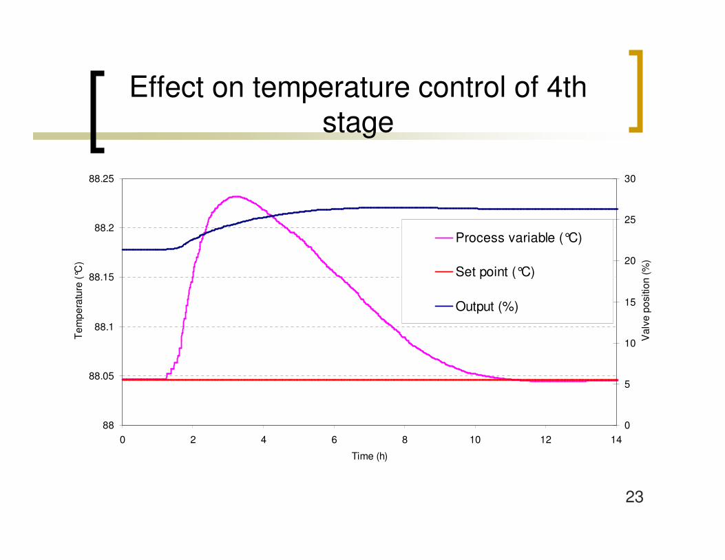
Effect on temperature control of 4thstage
88
88.05
88.1
88.15
88.2
88.25
0 2 4 6 8 10 12 14
Time (h)
Tem
pera
ture
(°C
)
0
5
10
15
20
25
30
Val
ve p
ositi
on (%
)
Process variable (°C)
Set point (°C)
Output (%)
24
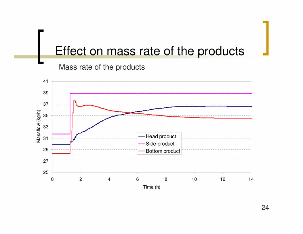
Effect on mass rate of the productsMass rate of the products
25
27
29
31
33
35
37
39
41
0 2 4 6 8 10 12 14
Time (h)
Mas
sflo
w (k
g/h)
Head productSide productBottom product
25
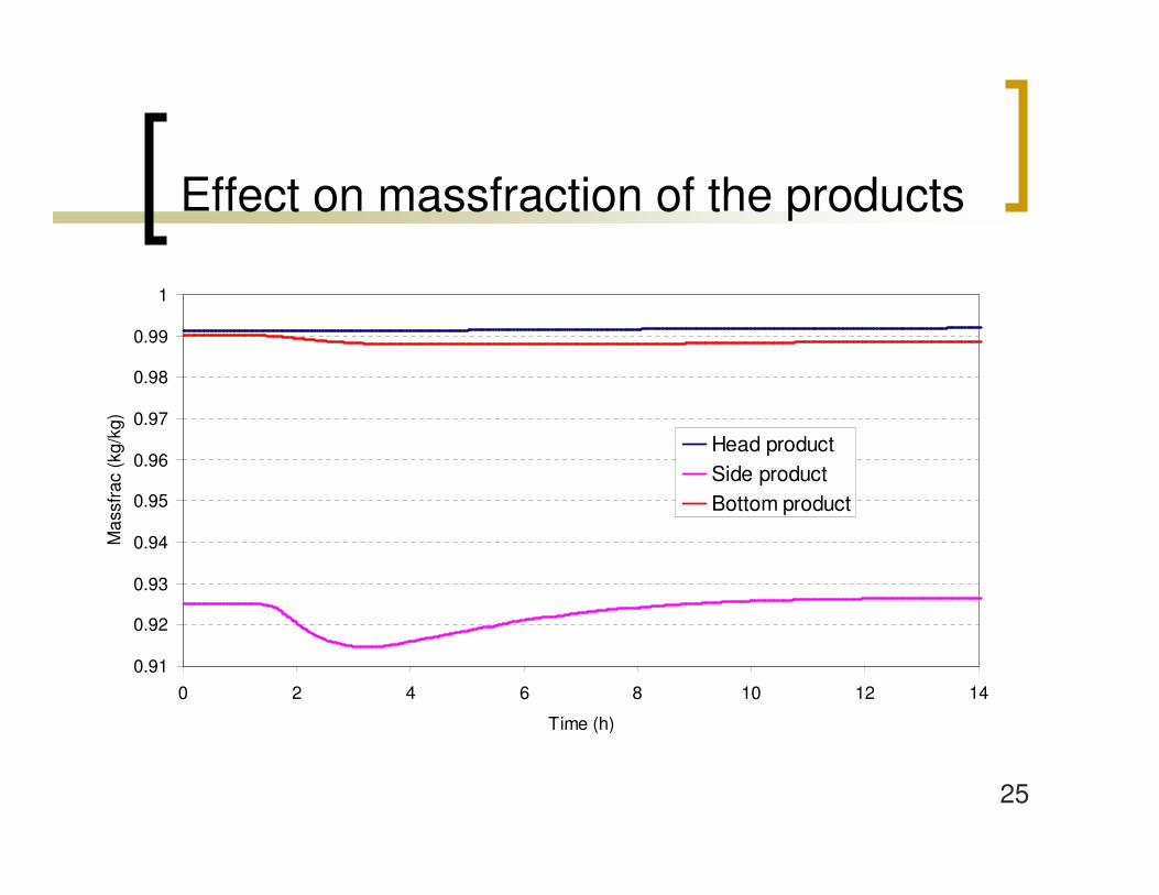
Effect on massfraction of the products
0.91
0.92
0.93
0.94
0.95
0.96
0.97
0.98
0.99
1
0 2 4 6 8 10 12 14
Time (h)
Mas
sfra
c (k
g/kg
)
Head productSide productBottom product
26
Summary
� The DWC was implemented in dynamic and steady-state simulator
� Main parameters of the column were analysed: optimum wall position is determinated
� Comparing DWC to side stream column: significant energy saving
� Controllability of the divided wall column was analysed: feasible control structure
27
Thank you for your attention!
� László Szabó is grateful for the support of the PhD Fellowship of the MOL Plc
� The financial support from the TAMOP-4.2.2-08/1/2008-0018 (Livable environment and healthier people – Bioinnovation and Green Technology research at the University of Pannonia) project is gratefully acknowledged.


