M AN843Speed Control of 3-Phase Induction Motor Using
PIC18 Microcontrollers
INTRODUCTION
Induction motors are the most widely used motors forappliances, industrial control, and automation; hence,they are often called the workhorse of the motion indus-try. They are robust, reliable, and durable. When poweris supplied to an induction motor at the recommendedspecifications, it runs at its rated speed. However,many applications need variable speed operations. Forexample, a washing machine may use different speedsfor each wash cycle. Historically, mechanical gear sys-tems were used to obtain variable speed. Recently,electronic power and control systems have matured toallow these components to be used for motor control inplace of mechanical gears. These electronics not onlycontrol the motor’s speed, but can improve the motor’sdynamic and steady state characteristics. In addition,electronics can reduce the system’s average powerconsumption and noise generation of the motor.
Induction motor control is complex due to its nonlinearcharacteristics. While there are different methods forcontrol, Variable Voltage Variable Frequency (VVVF) orV/f is the most common method of speed control inopen loop. This method is most suitable for applica-tions without position control requirements or the needfor high accuracy of speed control. Examples of theseapplications include heating, air conditioning, fans andblowers. V/f control can be implemented by using lowcost PICmicro microcontrollers, rather than usingcostly digital signal processors (DSPs).
Many PICmicro microcontrollers have two hardwarePWMs, one less than the three required to control a3-phase induction motor. In this application note, wewill generate a third PWM in software, using a generalpurpose timer and an I/O pin resource that are readilyavailable on the PICmicro microcontroller. This applica-tion note also covers the basics of induction motors anddifferent types of induction motors.
Induction Motor Basics
NAMEPLATE PARAMETERS
A typical nameplate of an induction motor lists thefollowing parameters:
• Rated terminal supply voltage in Volts• Rated frequency of the supply in Hz
• Rated current in Amps• Base speed in RPM• Power rating in Watts or Horsepower (HP)
• Rated torque in Newton Meters or Pound-Inches• Slip speed in RPM, or slip frequency in Hz• Winding insulation type - Class A, B, F or H
• Type of stator connection (for 3-phase only), star (Y) or delta (∆)
When the rated voltage and frequency are applied tothe terminals of an induction motor, it draws the ratedcurrent (or corresponding power) and runs at basespeed and can deliver the rated torque.
MOTOR ROTATION
When the rated AC supply is applied to the stator wind-ings, it generates a magnetic flux of constant magni-tude, rotating at synchronous speed. The flux passesthrough the air gap, sweeps past the rotor surface andthrough the stationary rotor conductors. An electro-motive force (EMF) is induced in the rotor conductorsdue to the relative speed differences between the rotat-ing flux and stationary conductors.
The frequency of the induced EMF is the same as thesupply frequency. Its magnitude is proportional to therelative velocity between the flux and the conductors.Since the rotor bars are shorted at the ends, the EMFinduced produces a current in the rotor conductors.The direction of the rotor current opposes the relativevelocity between rotating flux produced by stator andstationary rotor conductors (per Lenz's law).
To reduce the relative speed, the rotor starts rotating inthe same direction as that of flux and tries to catch upwith the rotating flux. But in practice, the rotor neversucceeds in 'catching up' to the stator field. So, therotor runs slower than the speed of the stator field. Thisdifference in speed is called slip speed. This slip speeddepends upon the mechanical load on the motor shaft.
Note: Refer to Appendix C for glossary oftechnical terms.
Author: Padmaraja YedamaleMicrochip Technology Inc.
2002 Microchip Technology Inc. DS00843A-page 1

AN843
The frequency and speed of the motor, with respect tothe input supply, is called the synchronous frequencyand synchronous speed. Synchronous speed isdirectly proportional to the ratio of supply frequencyand number of poles in the motor. Synchronous speedof an induction motor is shown in Equation 1.
EQUATION 1:
Synchronous speed is the speed at which the statorflux rotates. Rotor flux rotates slower than synchronousspeed by the slip speed. This speed is called the basespeed. The speed listed on the motor nameplate is thebase speed. Some manufacturers also provide the slipas a percentage of synchronous speed as shown inEquation 2.
EQUATION 2:
INDUCTION MOTOR TYPES
Based on the construction of the rotor, induction motorsare broadly classified in two categories: squirrel cagemotors and slip ring motors. The stator construction isthe same in both motors.
Squirrel Cage Motor
Almost 90% of induction motors are squirrel cagemotors. This is because the squirrel cage motor has asimple and rugged construction. The rotor consists of acylindrical laminated core with axially placed parallelslots for carrying the conductors. Each slot carries acopper, aluminum, or alloy bar. If the slots are semi-closed, then these bars are inserted from the ends.These rotor bars are permanently short-circuited atboth ends by means of the end rings, as shown inFigure 1. This total assembly resembles the look of asquirrel cage, which gives the motor its name. The rotorslots are not exactly parallel to the shaft. Instead, theyare given a skew for two main reasons:
a) To make the motor run quietly by reducing themagnetic hum.
b) To help reduce the locking tendency of the rotor.Rotor teeth tend to remain locked under the sta-tor teeth due to direct magnetic attractionbetween the two. This happens if the number ofstator teeth are equal to the number of rotorteeth.
FIGURE 1: TYPICAL SQUIRREL CAGE ROTOR
Note 1: The number of poles is the number ofparallel paths for current flow in the stator.
2: The number of poles is always an evennumber to balance the current flow.
3: 4-pole motors are the most widely usedmotors.
Synchronous Speed (Ns) = 120 x F/P
where:
F = rated frequency of the motor
P = number of poles in the motor
Base Speed N = Synchronous Speed – Slip Speed
(Synchronous Speed – Base Speed) x 100Synchronous Speed
Percent Slip =
Note 1: Percentage of slip varies with load on themotor shaft.
2: As the load increases, the slip alsoincreases.
Conductors End rings
Bearings
Shaft
Skewed Slots
DS00843A-page 2 2002 Microchip Technology Inc.
AN843
Slip Ring Motors
The windings on the rotor are terminated to three insu-lated slip rings mounted on the shaft with brushes rest-ing on them. This allows an introduction of an externalresistor to the rotor winding. The external resistor canbe used to boost the starting torque of the motor andchange the speed-torque characteristic. When runningunder normal conditions, the slip rings are short-circuited, using an external metal collar, which ispushed along the shaft to connect the rings. So, innormal conditions, the slip ring motor functions like asquirrel cage motor.
SPEED-TORQUE CHARACTERISTICS OF INDUCTION MOTORS
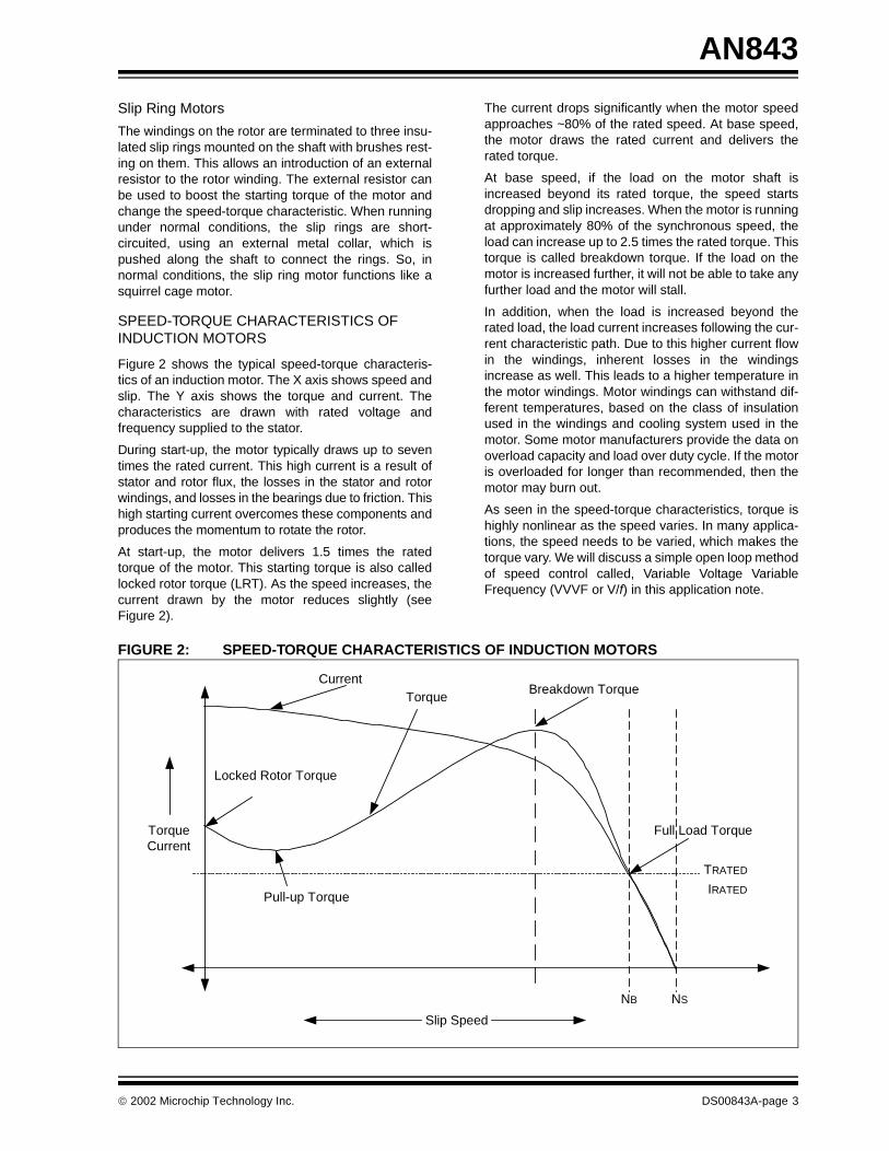
Figure 2 shows the typical speed-torque characteris-tics of an induction motor. The X axis shows speed andslip. The Y axis shows the torque and current. Thecharacteristics are drawn with rated voltage andfrequency supplied to the stator.
During start-up, the motor typically draws up to seventimes the rated current. This high current is a result ofstator and rotor flux, the losses in the stator and rotorwindings, and losses in the bearings due to friction. Thishigh starting current overcomes these components andproduces the momentum to rotate the rotor.
At start-up, the motor delivers 1.5 times the ratedtorque of the motor. This starting torque is also calledlocked rotor torque (LRT). As the speed increases, thecurrent drawn by the motor reduces slightly (seeFigure 2).
The current drops significantly when the motor speedapproaches ~80% of the rated speed. At base speed,the motor draws the rated current and delivers therated torque.
At base speed, if the load on the motor shaft isincreased beyond its rated torque, the speed startsdropping and slip increases. When the motor is runningat approximately 80% of the synchronous speed, theload can increase up to 2.5 times the rated torque. Thistorque is called breakdown torque. If the load on themotor is increased further, it will not be able to take anyfurther load and the motor will stall.
In addition, when the load is increased beyond therated load, the load current increases following the cur-rent characteristic path. Due to this higher current flowin the windings, inherent losses in the windingsincrease as well. This leads to a higher temperature inthe motor windings. Motor windings can withstand dif-ferent temperatures, based on the class of insulationused in the windings and cooling system used in themotor. Some motor manufacturers provide the data onoverload capacity and load over duty cycle. If the motoris overloaded for longer than recommended, then themotor may burn out.
As seen in the speed-torque characteristics, torque ishighly nonlinear as the speed varies. In many applica-tions, the speed needs to be varied, which makes thetorque vary. We will discuss a simple open loop methodof speed control called, Variable Voltage VariableFrequency (VVVF or V/f) in this application note.
FIGURE 2: SPEED-TORQUE CHARACTERISTICS OF INDUCTION MOTORS
TorqueCurrent
Slip Speed
NSNB
TRATED
IRATED
CurrentTorque
Locked Rotor Torque
Pull-up Torque
Breakdown Torque
Full Load Torque
2002 Microchip Technology Inc. DS00843A-page 3

AN843
V/f CONTROL THEORY
As we can see in the speed-torque characteristics, theinduction motor draws the rated current and deliversthe rated torque at the base speed. When the load isincreased (over-rated load), while running at basespeed, the speed drops and the slip increases. As wehave seen in the earlier section, the motor can take upto 2.5 times the rated torque with around 20% drop inthe speed. Any further increase of load on the shaft canstall the motor.
The torque developed by the motor is directly propor-tional to the magnetic field produced by the stator. So,the voltage applied to the stator is directly proportionalto the product of stator flux and angular velocity. Thismakes the flux produced by the stator proportional tothe ratio of applied voltage and frequency of supply.
By varying the frequency, the speed of the motor canbe varied. Therefore, by varying the voltage and fre-quency by the same ratio, flux and hence, the torquecan be kept constant throughout the speed range.
EQUATION 3:
This makes constant V/f the most common speedcontrol of an induction motor.
Figure 3 shows the relation between the voltage andtorque versus frequency. Figure 3 demonstrates volt-age and frequency being increased up to the basespeed. At base speed, the voltage and frequency reachthe rated values as listed in the nameplate. We candrive the motor beyond base speed by increasing thefrequency further. However, the voltage applied cannotbe increased beyond the rated voltage. Therefore, onlythe frequency can be increased, which results in thefield weakening and the torque available beingreduced. Above base speed, the factors governingtorque become complex, since friction and windagelosses increase significantly at higher speeds. Hence,the torque curve becomes nonlinear with respect tospeed or frequency.
FIGURE 3: SPEED-TORQUE CHARACTERISTICS WITH V/f CONTROL
Stator Voltage (V) ∝ [Stator Flux(φ)] x [Angular Velocity (ω)]
V ∝ φ x 2πf
φ ∝ V/f
Torqueoltage
Voltage
Vmin
Vrated
fmin fmax
Frequency
frated(base speed)
Voltage
TorqueVoltage
Frequency
DS00843A-page 4 2002 Microchip Technology Inc.

AN843
IMPLEMENTATION
Power
Standard AC supply is converted to a DC voltage byusing a 3-phase diode bridge rectifier. A capacitor fil-ters the ripple in the DC bus. This DC bus is used togenerate a variable voltage and variable frequencypower supply. A voltage source power inverter is usedto convert the DC bus to the required AC voltage andfrequency. In summary, the power section consists of apower rectifier, filter capacitor, and power inverter.
The motor is connected to the inverter as shown inFigure 4. The power inverter has 6 switches that arecontrolled in order to generate an AC output from theDC input. PWM signals generated from the micro-controller control these 6 switches. The phase voltageis determined by the duty cycle of the PWM signals. In
time, a maximum of three switches will be on, eitherone upper and two lower switches, or two upper andone lower switch.
When the switches are on, current flows from the DCbus to the motor winding. Because the motor windingsare highly inductive in nature, they hold electric energyin the form of current. This current needs to be dissi-pated while switches are off. Diodes connected acrossthe switches give a path for the current to dissipatewhen the switches are off. These diodes are also calledfreewheeling diodes.
Upper and lower switches of the same limb should notbe switched on at the same time. This will prevent theDC bus supply from being shorted. A dead time is givenbetween switching off the upper switch and switchingon the lower switch and vice versa. This ensures thatboth switches are not conductive when they changestates from on to off, or vice versa.
FIGURE 4: 3-PHASE INVERTER BRIDGE
PWM1
PWM6PWM5PWM4
PWM3PWM2
Motor
DC+
DC-
2002 Microchip Technology Inc. DS00843A-page 5

AN843
Control
To derive a varying AC voltage from the power inverter,pulse width modulation (PWM) is required to control theduration of the switches’ ON and OFF times. ThreePWMs are required to control the upper three switchesof the power inverter. The lower switches are controlledby the inverted PWM signals of the correspondingupper switch. A dead time is given between switchingoff the upper switch and switching on the lower switchand vice versa, to avoid shorting the DC bus.
PIC18XXX2 has two 10-bit PWMs implemented in thehardware. The PWM frequency can be set using thePR2 register. This frequency is common for bothPWMs. The upper eight bits of duty cycle are set usingthe register CCPRxL. The lower two bits are set inCCPxCON<5:4>. The third PWM is generated in thesoftware and output to a port pin.
SOFTWARE PWM IMPLEMENTATION
Timer2 is an 8-bit timer used to control the timing ofhardware PWMs. The main processor is interruptedwhen the Timer2 value matches the PR2 value, if a cor-responding interrupt enable bit is set.
Timer1 is used for setting the duty cycle of the softwarePWM (PWM3). In the Timer2 to PR2 match InterruptService Routine (ISR), the port pin designated forPWM3 is set to high. Also, the Timer1 is loaded with thevalue which corresponds to the PWM3 duty cycle. InTimer1 overflow interrupt, the port pin designated forPWM3 is cleared. As a result, the software andhardware PWMs have the same frequency.
The software PWM will lag by a fixed delay comparedto the hardware PWMs. To minimize the phase lag, theTimer2 to PR2 match interrupt should be given highestpriority while checking for the interrupt flags in the ISR.
The ISR has a fixed entry latency of 3 instructioncycles. If the interrupt is due to the Timer2 to PR2match then it takes 3 instruction cycles to check the flagand branch to the code section where the Timer2 toPR2 match task is present. Therefore, this makes aminimum of six instruction cycles delay, or phase shiftbetween the hardware PWM and software PWM, asshown in Figure 5.
The falling edge of software PWM trails the hardwarePWM by 8 instruction cycles. In the ISR, the TMR2 toPR2 match has a higher priority than the Timer1 over-flow interrupt. Thus, the control checks for TMR2 toPR2 match interrupt first. This adds 2 instruction cycleswhen the interrupt is caused by Timer1 overflow, mak-ing a total delay of 8 instruction cycles. Figure 5 showsthe hardware PWM and PWM generated by softwarefor the same duty cycle.
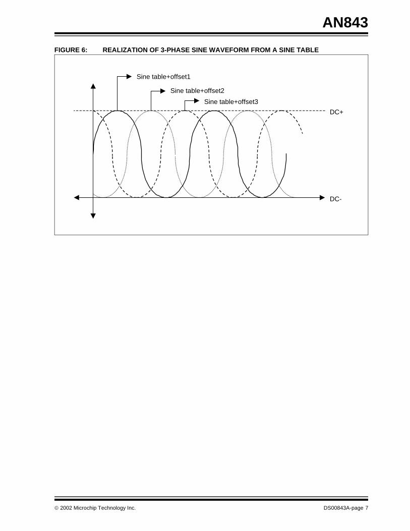
A sine table is created in the program memory, which istransferred to the data memory upon initialization.Three registers are used as the offset to the table. Eachof these registers will point to one of the values in thetable, such that they will have a 120 degrees phaseshift to each other as shown in the Figure 6. This formsthree sine waves, with 120 degrees phase shift to eachother.
After every Timer0 overflow interrupt, the value pointedto by the offset registers on the sine table is read. Thevalue read from the table is scaled based on the motorfrequency input, by multiplying by the frequency inputvalue to find the ratio of PWM, with respect to the max-imum DC bus. This value is loaded to the correspond-ing PWM duty cycle registers. Subsequently, the offsetregisters are updated for next access. If the directionkey is set to the motor to reverse rotation, then PWM1and PWM2 duty cycle values are loaded to PWM2 andPWM1 duty cycle registers, respectively. Typical codesection of accessing and scaling of the PWM duty cycleis as shown in Example 1.
FIGURE 5: TIMING DIAGRAM OF HARDWARE AND SOFTWARE PWMS
Hardware PWM
Software PWM
6 Cycles Delay
8 Cycles Delay
TMR2 to PR2 Match Timer1 Overflow
DS00843A-page 6 2002 Microchip Technology Inc.
AN843
FIGURE 6: REALIZATION OF 3-PHASE SINE WAVEFORM FROM A SINE TABLE
DC-
DC+
Sine table+offset1
Sine table+offset2
Sine table+offset3
2002 Microchip Technology Inc. DS00843A-page 7

AN843
EXAMPLE 1: SINE TABLE UPDATE;**********************************************************************************************;This routine updates the PWM duty cycle value according to the offset to the table by ;0-120-240 degrees.;This routine scales the PWM value from the table based on the frequency to keep V/F constant.;**********************************************************************************************
lfsr FSR0,(SINE_TABLE) ;Initialization of FSR0 to point the starting location of ;Sine table
;----------------------------------------------------------------------------------------------UPDATE_PWM_DUTYCYCLES
movf TABLE_OFFSET1,W ;Offset1 value is loaded to WREGmovf PLUSW0,W ;Read the value from the table start location + offset1bz PWM1_IS_0mulwf FREQUENCY ;Table value X Frequency to scale the table value movff PRODH,CCPR1L_TEMP ;based on the frequencybra UPDATE_PWM2
PWM1_IS_0clrf CCPR1L_TEMP ;Clear the PWM1 duty cycle register
;----------------------------------------------------------------------------------------------UPDATE_PWM2
movf TABLE_OFFSET2,W ;Offset2 value is loaded to WREGmovf PLUSW0,W ;Read the value from the table start location + offset2bz PWM2_IS_0 ;mulwf FREQUENCY ; Table value X Frequency to scale the table value movff PRODH,CCPR2L_TEMP ;based on the frequencybra UPDATE_PWM3
PWM2_IS_0clrf CCPR2L_TEMP ;Clear the PWM2 duty cycle register
;----------------------------------------------------------------------------------------------UPDATE_PWM3
movf TABLE_OFFSET3,W ;Offset2 value is loaded to WREGmovf PLUSW0,W ;Read the value from the table start location + offset3bz PWM3_IS_0mulwf FREQUENCY ;Table value X Frequency to scale the table value comf PRODH,PWM3_DUTYCYCLE;based on the frequencybra SET_PWM12
PWM3_IS_0clrf PWM3_DUTYCYCLE ;Clear the PWM3 duty cycle register
;---------------------------------------------------------------------------------------------SET_PWM12
btfss FLAGS,MOTOR_DIRECTION ;Is the motor direction = Reverse?bra ROTATE_REVERSE ;Yesmovff CCPR1L_TEMP,CCPR1L ;No, Forwardmovff CCPR2L_TEMP,CCPR2L ;Load PWM1 & PWM2 to duty cycle registersbsf PORT_LED1,LED1 ;LED1-ON indicating motor running forwardreturn
;----------------------------------------------------------------------------------------------ROTATE_REVERSE ;Motor direction reverse
movff CCPR2L_TEMP,CCPR1L ;Load PWM1 & PWM2 to duty cycle registersmovff CCPR1L_TEMP,CCPR2Lbcf PORT_LED1,LED1;LED1-OFF indicating motor running reversereturn
;----------------------------------------------------------------------------------------------
DS00843A-page 8 2002 Microchip Technology Inc.

AN843
The three PWMs are connected to the driver chip(IR21362). These three PWMs switch the upper threeswitches of the power inverter. The lower switches arecontrolled by the inverted PWM signals of the corre-sponding upper switch. The driver chip generates200 ns of dead time between upper and lower switchesof all phases.
A potentiometer connected to a 10-bit ADC channel onthe PICmicro microcontroller determines the motorspeed. The microcontroller uses the ADC results to cal-culate the duty cycle of the PWMs and thus, the motorfrequency. The ADC is checked every 2.2 milliseconds,which provides smooth frequency transitions. Timer0 isused for the timing of the motor frequency. The Timer0period is based on the ADC result, the main crystal fre-
quency, and the number of sine table entries. NewPWM duty cycles are loaded to the corresponding dutycycle registers during the Timer0 overflow InterruptService Routine. So, the duty cycle will remain thesame until the next Timer0 overflow interrupt occurs, asshown in Figure 7.
EQUATION 4:
FIGURE 7: TIMER0 OVERFLOW AND PWM
Timer0 Reload Value =
FOSC
4
FFFFh –Sine samples per cycle x Timer0 Prescaler x ADC
Timer0 overflow Interrupt
Timer2 to PR2 match Interrupt Timer1 overflow Interrupt
Average voltage
Time
VoltsVolts
Time
2002 Microchip Technology Inc. DS00843A-page 9

AN843
System Overview
Figure 8 shows an overall block diagram of the powerand control circuit. A potentiometer is connected to ADChannel 0. The PICmicro microcontroller reads thisinput periodically to get the new speed or frequency ref-erence. Based on this AD result, the firmware deter-mines the scaling factor for the PWM duty cycle. TheTimer0 reload value is calculated based on this input todetermine the motor frequency. PWM1 and PWM2 arethe hardware PWMs (CCP1 and CCP2). PWM3 is thePWM generated by software. The output of these threePWMs are given to the higher and lower input pins ofthe IGBT driver as shown in Figure 8. The IGBT driverhas inverters on the lower input pins and adds dead-
time between the respective higher and lower PWMs.This driver needs an enable signal, which is controlledby the microcontroller. The IGBT driver has two FAULTmonitoring circuits, one for over current and the secondfor under voltage. Upon any of these FAULTS, the out-puts are driven low and the FAULT pin shows that aFAULT has occurred. If the FAULT is due to the overcurrent, it can be automatically reset after a fixed timedelay, based on the resistor and capacitor timeconstant connected to the RCIN pin of the driver.
The main 3-phase supply is rectified by using the3-phase diode bridge rectifier. The DC ripple is filteredby using an electrolytic capacitor. This DC bus isconnected to the IGBTs for inverting it to a V/f supply.
FIGURE 8: BLOCK DIAGRAM OF 3-PHASE INDUCTION MOTOR CONTROL
CONCLUSION
To control the speed of a 3-phase induction motor inopen loop, supply voltage and frequency need to bevaried with constant ratio to each other. A low cost solu-tion of this control can be implemented in a PICmicromicrocontroller. This requires three PWMs to control a3-phase inverter bridge. Many PICmicro micro-controllers have two hardware PWMs. The third PWMis generated in software and output to a port pin.
TABLE 1: MEMORY REQUIREMENTS
HIN1HIN2HIN3
LIN1LIN2LIN3
HOut1
HOut2
HOut3
LOut1
LOut2
LOut3FAULT
EnIGBTDriver
PWM1PWM2PWM3
ADC
FAULT
En
PIC18XXX
IGBTH1
IGBTH2
IGBTH3
IGBTL1
IGBTL2
IGBTL3
3-PhaseInverter
3-Phase DiodeBridge Rectifier
3-Phase ACInput
3-Phase Induction Motor
Run/Stop
Fwd/Rev
Potentiometer
Capacitor
Memory Bytes
Program 0.9 Kbytes
Data 36 bytes
DS00843A-page 10 2002 Microchip Technology Inc.

AN843
APPENDIX A: TEST RESULTS
TABLE A-1: TEST RESULTS
Above tests are conducted on the motor with the following specifications:
• Terminal voltage: 208-220 Volts
• Frequency: 60 Hz• Horsepower: ½ HP• Speed: 1725 RPM
• Current: 2.0 Amps• Frame: 56 NEMA
Test # Set Frequency (Hz) Set Speed (RPM) Actual Speed (RPM) Speed Regulation (%)
1 7.75 223 208 -1.875
2 10.5 302 286 -0.89
3 13.25 381 375 -0.33
4 16.75 482 490 +0.44
5 19.0 546 548 +0.11
6 20.75 597 590 +0.39
7 24.0 690 668 -1.22
8 27.0 776 743 -1.83
9 29.0 834 834 0.0
10 33.0 949 922 -1.5
11 38.0 1092 1078 0.78
12 45.75 1315 1307 -0.44
13 55.5 1596 1579 -0.94
14 58.25 1675 1644 -1.72
15 60 1725 1712 -0.72
2002 Microchip Technology Inc. DS00843A-page 11
AN843
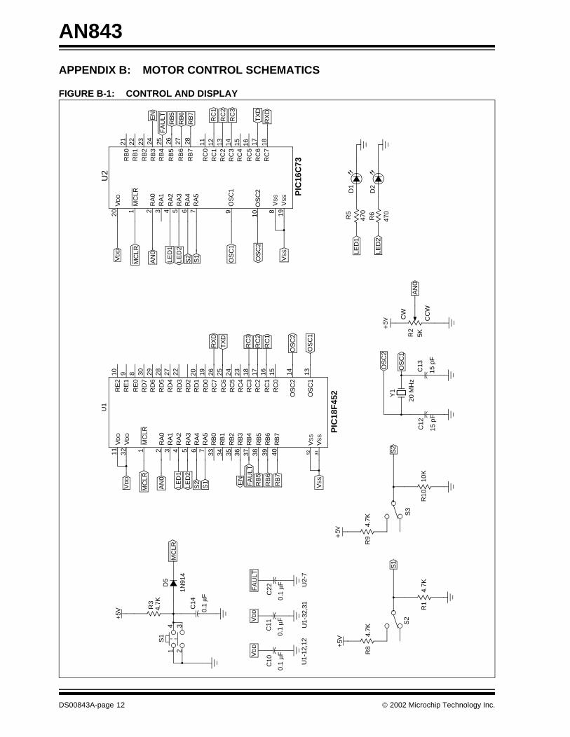
APPENDIX B: MOTOR CONTROL SCHEMATICS
FIGURE B-1: CONTROL AND DISPLAY
S1
VD
D
S2
AN
0
U1-
12,1
2
VD
D
U2-
7U
1-32
,31
OS
C1
OS
C2
+5V
R3
D5
4.7K
MC
LR1
42
3
0.1
µF
C14
1N91
4
S1
AN
0
MC
LR
S2
LED
2LE
D1
S1 FA
ULT
RB
5
RB
6
RB
7
U1
11 32 1M
CLR
VD
D
VD
D
RA
1R
A2
RA
3R
A4
RA
5
2 3 4 5 6 7 33 34 35 36 37 38 39 40
10 9 8 30 29 28 27 22
RE
2R
E1
RE
0R
D7
RD
6R
D5
RD
4
RD
3R
D2
RD
1R
D0
RC
7
RC
6R
C5
RC
4
RC
2
RC
1R
C0
OS
C2
OS
C1
RC
3
20 19 26 25 24 23 18 17 16 15 14 13
RB
0R
B1
RB
2R
B3
RB
4
RB
5R
B6
RB
7
VS
S
VS
SV
SS
PIC
18F
452
RX
D
TX
D
RC
3
RC
2
RC
1
OS
C2
OS
C1
FA
ULT
VD
D
0.1
µF
C22
0.1
µF
C11
0.1
µF
C10
EN
4.7K
R8+
5V
4.7K
R1
S2
4.7K
R9
10K
R10
S3
15 p
F
C12
15 p
F
C13
20 M
Hz
Y1
5KR2
CC
W
CW
LED
147
0
R5
470
R6
LED
2
D1
D2
VD
D
AN
0
MC
LR
S2
LED
2LE
D1
S1
OS
C1
OS
C2
1 2 3 4 5 6 7
RA
0R
A1
RA
2R
A3
RA
4R
A5
MC
LR
VD
D20
U2
10
9
OS
C2
OS
C1
VS
S
VS
S
VS
S PIC
16C
73
198
RB
0R
B1
RB
2R
B3
RB
4
RB
5
RB
6
RB
7
21 22 23
EN
FA
ULT
RB
5
RB
6
RB
7
26 27 2824 25 13 14 1511 12R
C1
RC
2
RC
3
16 17 18R
XD
TX
D
RC
2R
C3
RC
4
RC
5R
C6
RC
7
RC
0R
C1
RA
0
DS00843A-page 12 2002 Microchip Technology Inc.

AN843
FIGURE B-2: POWER SUPPLY
+20
V
Opt
iona
l
C25
0.1
µF0.
1 µF
C23
100
µF
C24
10K
R7
6.8K
R22
CN
51 2
VD
D
VS
S
INO
UT
CO
M
VR
2
LM34
0T-5
.01
3
2
+5V
D6
R40
470
Jum
per
2002 Microchip Technology Inc. DS00843A-page 13
AN843
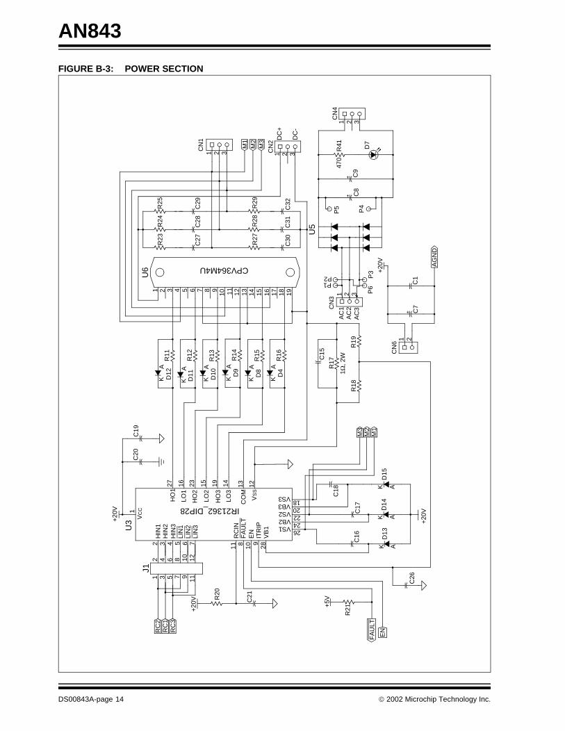
FIGURE B-3: POWER SECTION
M2
AC
3
AG
ND
DC
+
+5V
+20
V
+20
V
M1
M3
AC
2A
C1
+20
V
DC
-
+20
V
RC
2R
C1
RC
3
2 4 6 8 10 12
2 3 4 5 6 7
1 3 5 7 9 11
J1
HIN
3H
IN2
LIN
1
HIN
1
LIN
2LI
N3
11 8 109
28
EN
FA
ULT
ITR
IP
RC
IN
VB
1
HO
2
LO1
LO2
HO
1
HO
3
LO3
VC
C1U
3
27 16 23 15 19 14 13 12
C20
C19
R20
C21
IR21362_DIP28
KA
D12
KA
D11
R12
R11
KA
D10
R13
KA
D9
R14
KA
D8
R15
KA
D4
R16
2 3 4 5 6 7 8 910 11 121 13 14 15 16 17 18 19
U6
R23
R24
C27
R25
C28
C29
1 2 3CN
1
M1
M2
M3
CN
2
R27
R28
R29
C30
C32
C31
U5
CPV364M4UP2P1
CN
3
321
C8
C9
R41
C7
P4
470
D7
1 2 3
CN
4
C1
P6
P3
1 2
CN
6
R17
R19
R18
1 Ω, 2
WC15
C18
C17
D15
K AD
14K A
D13
AK
CO
M
VS
S
2624222018
VS1VB2VS2VB3VS3
C16
C26
R21
FA
ULT
EN
1 2 3
P5
DS00843A-page 14 2002 Microchip Technology Inc.
AN843
APPENDIX C: GLOSSARY
Air Gap
Uniform gap between the stator and rotor.
Angular Velocity
Velocity in radians (2π x frequency).
Asynchronous Motor
Type of motor in which the flux generated by the statorand rotor have different frequencies.
Base Speed
Speed specified on the nameplate of an inductionmotor.
Break Down Torque
Maximum torque on the speed-torque characteristicsat approximately 80% of base speed.
EMF
Electromotive Force. The potential generated by a cur-rent carrying conductor when it is exposed to magneticfield. EMF is measured in volts.
Full Load Torque
Rated torque of the motor as specified on thenameplate.
IGBT
Insulated Gate Bipolar Transistor.
Lenz’s Law
The Electromotive force (EMF) induced in a conductormoving perpendicular to a magnetic field tends tooppose that motion.
Locked Rotor Torque
Starting torque of the motor.
Pull-up Torque
Torque available on the rotor at around 20% of basespeed.
Rotor
Rotating part of the motor.
Slip Speed
Synchronous speed minus base speed.
Stator
Stationary part of the motor.
Synchronous Motor
Type of motor in which the flux generated by the statorand rotor have the same frequencies. The phase maybe shifted.
Synchronous Speed
Speed of the motor corresponding to the ratedfrequency.
Torque
Rotating force in Newton-Meters or Pound-Inches.
2002 Microchip Technology Inc. DS00843A-page 15
AN843
APPENDIX D: SOFTWARE DISCUSSED IN THIS TECHNICAL BRIEF
Because of its overall length, a complete source file list-ing is not provided. The complete source code is avail-able as a single WinZip archive file, which may bedownloaded from the Microchip corporate web site at:
www.microchip.com
DS00843A-page 16 2002 Microchip Technology Inc.

Note the following details of the code protection feature on PICmicro® MCUs.
• The PICmicro family meets the specifications contained in the Microchip Data Sheet.• Microchip believes that its family of PICmicro microcontrollers is one of the most secure products of its kind on the market today,
when used in the intended manner and under normal conditions.• There are dishonest and possibly illegal methods used to breach the code protection feature. All of these methods, to our knowl-
edge, require using the PICmicro microcontroller in a manner outside the operating specifications contained in the data sheet. The person doing so may be engaged in theft of intellectual property.
• Microchip is willing to work with the customer who is concerned about the integrity of their code.• Neither Microchip nor any other semiconductor manufacturer can guarantee the security of their code. Code protection does not
mean that we are guaranteeing the product as “unbreakable”.• Code protection is constantly evolving. We at Microchip are committed to continuously improving the code protection features of
our product.
If you have any further questions about this matter, please contact the local sales office nearest to you.
Information contained in this publication regarding deviceapplications and the like is intended through suggestion onlyand may be superseded by updates. It is your responsibility toensure that your application meets with your specifications.No representation or warranty is given and no liability isassumed by Microchip Technology Incorporated with respectto the accuracy or use of such information, or infringement ofpatents or other intellectual property rights arising from suchuse or otherwise. Use of Microchip’s products as critical com-ponents in life support systems is not authorized except withexpress written approval by Microchip. No licenses are con-veyed, implicitly or otherwise, under any intellectual propertyrights.
2002 Microchip Technology Inc.
Trademarks
The Microchip name and logo, the Microchip logo, FilterLab,KEELOQ, microID, MPLAB, PIC, PICmicro, PICMASTER,PICSTART, PRO MATE, SEEVAL and The Embedded ControlSolutions Company are registered trademarks of Microchip Tech-nology Incorporated in the U.S.A. and other countries.
dsPIC, ECONOMONITOR, FanSense, FlexROM, fuzzyLAB,In-Circuit Serial Programming, ICSP, ICEPIC, microPort,Migratable Memory, MPASM, MPLIB, MPLINK, MPSIM,MXDEV, MXLAB, PICC, PICDEM, PICDEM.net, rfPIC, SelectMode and Total Endurance are trademarks of MicrochipTechnology Incorporated in the U.S.A.
Serialized Quick Turn Programming (SQTP) is a service markof Microchip Technology Incorporated in the U.S.A.
All other trademarks mentioned herein are property of theirrespective companies.
© 2002, Microchip Technology Incorporated, Printed in theU.S.A., All Rights Reserved.
Printed on recycled paper.
DS00843A - page 17
Microchip received QS-9000 quality system certification for its worldwide headquarters, design and wafer fabrication facilities in Chandler and Tempe, Arizona in July 1999 and Mountain View, California in March 2002. The Company’s quality system processes and procedures are QS-9000 compliant for its PICmicro® 8-bit MCUs, KEELOQ® code hopping devices, Serial EEPROMs, microperipherals, non-volatile memory and analog products. In addition, Microchip’s quality system for the design and manufacture of development systems is ISO 9001 certified.
DS00843A-page 18 2002 Microchip Technology Inc.
MAMERICASCorporate Office2355 West Chandler Blvd.Chandler, AZ 85224-6199Tel: 480-792-7200 Fax: 480-792-7277Technical Support: 480-792-7627Web Address: http://www.microchip.comRocky Mountain2355 West Chandler Blvd.Chandler, AZ 85224-6199Tel: 480-792-7966 Fax: 480-792-4338
Atlanta500 Sugar Mill Road, Suite 200BAtlanta, GA 30350Tel: 770-640-0034 Fax: 770-640-0307Boston2 Lan Drive, Suite 120Westford, MA 01886Tel: 978-692-3848 Fax: 978-692-3821Chicago333 Pierce Road, Suite 180Itasca, IL 60143Tel: 630-285-0071 Fax: 630-285-0075Dallas4570 Westgrove Drive, Suite 160Addison, TX 75001Tel: 972-818-7423 Fax: 972-818-2924DetroitTri-Atria Office Building 32255 Northwestern Highway, Suite 190Farmington Hills, MI 48334Tel: 248-538-2250 Fax: 248-538-2260Kokomo2767 S. Albright Road Kokomo, Indiana 46902Tel: 765-864-8360 Fax: 765-864-8387Los Angeles18201 Von Karman, Suite 1090Irvine, CA 92612Tel: 949-263-1888 Fax: 949-263-1338New York150 Motor Parkway, Suite 202Hauppauge, NY 11788Tel: 631-273-5305 Fax: 631-273-5335San JoseMicrochip Technology Inc.2107 North First Street, Suite 590San Jose, CA 95131Tel: 408-436-7950 Fax: 408-436-7955Toronto6285 Northam Drive, Suite 108Mississauga, Ontario L4V 1X5, CanadaTel: 905-673-0699 Fax: 905-673-6509
ASIA/PACIFICAustraliaMicrochip Technology Australia Pty LtdSuite 22, 41 Rawson StreetEpping 2121, NSWAustraliaTel: 61-2-9868-6733 Fax: 61-2-9868-6755China - BeijingMicrochip Technology Consulting (Shanghai)Co., Ltd., Beijing Liaison OfficeUnit 915Bei Hai Wan Tai Bldg.No. 6 Chaoyangmen Beidajie Beijing, 100027, No. ChinaTel: 86-10-85282100 Fax: 86-10-85282104China - ChengduMicrochip Technology Consulting (Shanghai)Co., Ltd., Chengdu Liaison OfficeRm. 2401, 24th Floor, Ming Xing Financial TowerNo. 88 TIDU StreetChengdu 610016, ChinaTel: 86-28-86766200 Fax: 86-28-86766599China - FuzhouMicrochip Technology Consulting (Shanghai)Co., Ltd., Fuzhou Liaison OfficeUnit 28F, World Trade PlazaNo. 71 Wusi RoadFuzhou 350001, ChinaTel: 86-591-7503506 Fax: 86-591-7503521China - ShanghaiMicrochip Technology Consulting (Shanghai)Co., Ltd.Room 701, Bldg. BFar East International PlazaNo. 317 Xian Xia RoadShanghai, 200051Tel: 86-21-6275-5700 Fax: 86-21-6275-5060China - ShenzhenMicrochip Technology Consulting (Shanghai)Co., Ltd., Shenzhen Liaison OfficeRm. 1315, 13/F, Shenzhen Kerry Centre,Renminnan LuShenzhen 518001, ChinaTel: 86-755-2350361 Fax: 86-755-2366086China - Hong Kong SARMicrochip Technology Hongkong Ltd.Unit 901-6, Tower 2, Metroplaza223 Hing Fong RoadKwai Fong, N.T., Hong KongTel: 852-2401-1200 Fax: 852-2401-3431IndiaMicrochip Technology Inc.India Liaison OfficeDivyasree Chambers1 Floor, Wing A (A3/A4)No. 11, O’Shaugnessey RoadBangalore, 560 025, IndiaTel: 91-80-2290061 Fax: 91-80-2290062
JapanMicrochip Technology Japan K.K.Benex S-1 6F3-18-20, ShinyokohamaKohoku-Ku, Yokohama-shiKanagawa, 222-0033, JapanTel: 81-45-471- 6166 Fax: 81-45-471-6122KoreaMicrochip Technology Korea168-1, Youngbo Bldg. 3 FloorSamsung-Dong, Kangnam-KuSeoul, Korea 135-882Tel: 82-2-554-7200 Fax: 82-2-558-5934SingaporeMicrochip Technology Singapore Pte Ltd.200 Middle Road#07-02 Prime CentreSingapore, 188980Tel: 65-6334-8870 Fax: 65-6334-8850TaiwanMicrochip Technology (Barbados) Inc., Taiwan Branch11F-3, No. 207Tung Hua North RoadTaipei, 105, TaiwanTel: 886-2-2717-7175 Fax: 886-2-2545-0139
EUROPEAustriaMicrochip Technology Austria GmbHDurisolstrasse 2A-4600 WelsAustriaTel: 43-7242-2244-399Fax: 43-7242-2244-393DenmarkMicrochip Technology Nordic ApSRegus Business CentreLautrup hoj 1-3Ballerup DK-2750 DenmarkTel: 45 4420 9895 Fax: 45 4420 9910FranceMicrochip Technology SARLParc d’Activite du Moulin de Massy43 Rue du Saule TrapuBatiment A - ler Etage91300 Massy, FranceTel: 33-1-69-53-63-20 Fax: 33-1-69-30-90-79GermanyMicrochip Technology GmbHGustav-Heinemann Ring 125D-81739 Munich, GermanyTel: 49-89-627-144 0 Fax: 49-89-627-144-44ItalyMicrochip Technology SRLCentro Direzionale Colleoni Palazzo Taurus 1 V. Le Colleoni 120041 Agrate BrianzaMilan, Italy Tel: 39-039-65791-1 Fax: 39-039-6899883United KingdomMicrochip Ltd.505 Eskdale RoadWinnersh TriangleWokingham Berkshire, England RG41 5TUTel: 44 118 921 5869 Fax: 44-118 921-5820
05/16/02
WORLDWIDE SALES AND SERVICE


